review of pim (pipeline insertion method) technology · polyethylene). pim is the foremost...
TRANSCRIPT

USACERL Technical Manuscript N-91/08September 1991
US Army Corpsof EngineersConstruction EngineeringResearch Laboratory
AD-A243 963
Review of PIM (Pipeline InsertionMethod) TechnologyRichard J. Scholze, Jr. tStephen W. Maloney - EEdgar D. Smith E L EPrakash M. Temkar aJsN07 1992 W
The U.S. Army Construction EngineeringResearch Laboratory (USACERL) conducted the LIfirst demonstration of PIM (Pipeline InsertionMethod, formerly Pipe Insertion Machine)technology for sewer rehabilitation in the UnitedStates in 1987, complete with a battery ofphysical testing for vibration and soil deformation.The technology, first developed for gas mainreplacement, uses an impact mole to burst theexisting pipe outward into the surrounding soiland replace it at the same rate with HDPE (HighDensity Polyethylene). PIM is the foremosttrenchless technology which can replace existingpipe with equal or larger diameter pipe. Thetechnology is applicable to sewer, water, and gasmains and can be cost-competitive with opentrench techniques in specialized circumstances,such as areas with high surface restoration costs:under paved areas, through environmentallysensitive areas, etc. A body of knowledge hasdeveloped during the past two years as thenumber of users has increased. This paper willsummarize the existing state-of-the-art of thetechnology with wastewater collection systems 9 "including information on applicability, economics, 92 00122advantages and disadvantages, and lessons- I I 111learned.
Approved for public release; distribution is unlimited.
( . )
The contents of this report are not to be used for advertising, publication,or promotional purposes. Citation of trade names does not constitute anofficial indorsement or approval of the use of such commercial products.The findings of this report are not to be construed as an official Depart-ment of the Army position, unless so designated by other authorizeddocuments.
DESTROY THIS REPORT WHEN IT IS NO LONGER NEEDED
DO NOT RETURN IT TO THE ORIGINATOR

Form ApprovedREPORT DOCUMENTATION PAGE I o. ApprovedPAG O MB No. 0704-01 88Public reporting burden for this collection of information is estimated to average 1 hour per response, including the time for reviewing instructions, searching existing data sources,gathering and maintaining the data needed, and completing and reviewing the collection of information. Send comments regarding this burden estimate or any other aspect of tinscolect~on of information. including suggestions for reducing this burden, to Washington Headquarters Services. Directorate for information Operations and Reports. 1215 JeffersonDaws Highway, Sufe 1204, Arlington. VA 22202-4302, and to the Office of Management and Budget, Paperwork Reduction Project (0704-0188). Washington. DC 20503.
i. AGENCY USE ONLY (Leave Blank) 2. REPORT DATE 3. REPORT TYPE AND DATES COVERED
September 1991 Final4. TITLE AND SUBTITLE 5. FUNDING NUMBERS
Review of PIM (Pipeline Insertion Method) Technology
6. AUTHOR(S) WU K89
Richard J. Scholze, Stephen W. Maloney, Edgar D. Smith, andPrakash M. Temkar
7. PERFORMING ORGANIZATION NAME(S) AND ADDRESS(ES) 8. PERFORMING ORGANIZATION
REPORT NUMBERU.S. Army Construction Engineering Research Laboratory (USACERL)2902 Newmark Drive, PO Box 9005 TM N-91/08Champaign. IL 61826-9005
9. SPONSORING MONITORING AGENCY NAME(S) AND ADDRESS(ES) 10. SPONSORINGMONITORING
USAEHSC AGENCY REPORT NUMBER
ATTN: CEHSC-FU-SBldg 358Fort Belvoir, VA 22060
11. SUPPLEMENTARY NOTES
Copies are available from the National Technical Information Service, 5285 Port Royal Road,Springfield, VA 22161
12a. DISTRIBUTION/AVAILABILITY STATEMENT 12b. DISTRIBUTION CODE
Approved for public release; distribution is unlimited.
13. ABSTRACT (Maximum 200 words)
The U.S. Army Construction Engineering Research Laboratory (USACERL) conducted the firstdemonstration of PIM (Pipeline Insertion Method, formerly Pipe Insertion Machine) technology for sewerrehabilitation in the United States in 1987, complete with a battery of physical testing for vibration and soildeformation. The technology, first developed for gas main replacement, uses an impact mole to burst theexisting pipe outward into the surrounding soil and replace it at the same rate with HDPE (Htigh DensityPolyethylene). PIM is the foremost trenchless technology which can replace existing pipe with equal orlarger diameter pipe. The technology is applicable to sewer, water, and gas mains and can be cost-competitive with open trench techniques in specialized circumstances, such as areas with high surfacerestoration costs: under paved areas, through environmentally sensitive areas, etc. A body of knowledgehas developed during the past two years as the number of users has increased. This paper will summarizethe existing state-of-the-art of the technology with wastewater collection systems including information onapplicability, economics, advantages and disadvantages, and lessons-learned.
4 SUBJECT TERMS 15 NUMBER OF PAGES
Pipelines - design and construction 16Pipe plastic 16 PRICE CODE
'7 SECURITY CLASSIFICATION 18 SECURITY CLASSIFICATION 19 SECURITY CLASSIFICATION 20 LIMITATION OF ABSTRACTOF REPORT OF THIS PAGE OF ABSTRACT
Unclassified Unclassified Unclassified SAR
NSN 7540.01 280 5500 StrxWd Form 298 (Re 2 890P5c-b.d 55 ANSI Srd 231 1298 02

FOREWORD
This is a reprint of a paper that appeared in Pipeline Design and Installation,Proceedings of the International Conference, sponsored by the American PlanningCommittee of the Pipeline Division of the American Society of Civil Engineers, March25-27, 1990. The paper was based on research being done for the U.S. Army Engineeringand Housing Support Center (USAEHSC) as part of the Facilities EngineeringApplications Program (FEAP), Work Unit K89 "Rehabilitation of Sewage Pipes." Workwas performed by the Environmental Division (EN) of the U.S. Army ConstructionEngineering Research Laboratory (USACERL).
Special thanks is expressed to Joye Kurasaki and the Central Contra Costa SanitaryDistrict in Martinez, California for their information and cooperation.
The USACERL principal investigator was Richard J. Scholze. Assistance wasprovided by Stephen W. Maloney, Dr. Edgar D. Smith, and Dr. Prakash M. Temkar. Dr.Edward W. Novak is Acting Chief of USACERL-EN.
COL Everett R. Thomas is Commander and Director of USACERL, and Dr. L.R.Shaffer is Technical Director.
2

CONTENTS
Page
FOREWORD 2
INTRODUCTION............................................... 5
TECHNOLOGY................................................ 5
PINI APPLICATION FOR SEWERS................................ 8
BENEFITS OF TECHNOLOGY....................................8
FORT BELVOIR APPLICATION.................................. 8
ECONOMICS................................................. 10
LESSONS-LEARNED...........................................11t
SUMIMARY................................................... 14
REFERENCES................................................. 14
DISTRIBUTION
A-1
3

PIPELINE INSERTION METHOD
REVIEW OF PIM (PIPELINE INSERTION METHOD) TECHNOLOGY
Introduction
An "INFRASTRUCTURE CRISIS," cry newspaper and magazine headlines, hashit this country for roads, bridges, sewers, waterlines, treatment plants, and utilities.Wastewater collection systems, while being the largest capital investment by a wastewaterutility, traditionally receive little attention until a problem arises; because the componentsare out of sight, they're out of mind. Many communities face serious problems with alarge percentage of sewers being collapsed or in need of urgent attention. Othersexperience hydraulic overload due to new development or inflow/infiltration. Repair,renovation, and replacement are the major options for rehabilitation of sewers. On-linereplacement, i.e. "no-dig" or trenchless technologies, have recently been receivingincreased attention as innovative, cost-effective rehabilitation techniques are sought. Onetechnology which is receiving attention is the pipeline insertion method (PIM) which canreplace existing sewers with a larger size pipe. This technology can increase hydrauliccapacity while supplying new lines. The proprietary technique is protected with a methodpatent and marketed in the U.S. by PIM Corporation of Piscataway, NJ.
Technology
The PIM concept and technology were developed in Great Britain, following anoriginal proposal for experimental research in the U.S.S.R. as a method for replacementof cast iron gas mains. Since then the technology has seen additional use for sewer andwater lines and, although primarily European in usage, the process is becoming morewidely used in North America. In addition to the applications discussed in this paper, thetechnology has been used in suburban Washington, D.C., Long Island (New York), andRegina and Edmonton (Canada).
"Impact mole" or "pipe bursting" technology involves installing larger pipes intothe place of existing older lines. The technology consists of fragmenting the pipe in placeand forcing it into the surrounding soil with an impact mole. A new pipe of high densitypolyethylene is then pushed into the existing sewage collection route manhole to manhole.Thus, it can be installed without disturbing the surface. PIM has the capability to not onlyreplace size for size but to upsize existing pipe, up to 50 percent greater cross sectionalarea. The process requires excavation for insertion pits at every other manhole and areception pit for removal of the mole. In addition, smaller excavation pits are requiredfor every functioning lateral connection.
The bursting of the pipe material is accomplished by the use of pneumatic (Figure1) or hydraulic bursters. In the hydraulic system, the mole is towed by a winch, whilethe new pipe is towed behind the mole. In the pneumatic system for replacing pressurepipe, the mole is guided by a winch and the pipe is tensioned and towed behind the mole.In the pneumatic system for nonpressure pipe, the mole is guided by the winch, and thenew pipe is hydraulically jacked behind the mole, enabling it to achieve greater distances(Figure 2).
5

PIPELINE DESIGN AND INSTALLATION
A.k
Figure 1. Impact Mole Just Before Connection to HDPE Pipe,Showing Airline Inside HDPE Pipe.
r if
1.4 P".-If
9 44.
Figure 2. Diagram of Pipe Insertion Methodology for On-lineSewer Replacement.
6

PIPELINE INSERTION METHOD
Distinct variants have evolved: a pressure pipe replacement system and anon-pressure pipe replacement system. These are differentiated by the characteristics ofthe pipes themselves. Pressure pipes (e.g. gas) tend to be of smaller diameter and laid ata more shallow depth than the larger diameter gravity systems. Initial development of thesystem concentrated on small-diameter gas mains. The gas mains were originallyconstructed of cast iron, so a PVC-liner pipe is used as a precaution against damage tothe HDPE by metal fragments. The PVC liner is first pulled into place behind the impactmole as it breaks up the existing pipe. Then a HDPE pipe is slid into place inside theprotective PVC liner. Non-pressure pipes found in sewer systems are made of morebrittle materials such as vitrified clay, which pose less of a threat to the HDPE pipe, thusno PVC liner is used. These pipes also tend to be much larger, making it difficult for theimpact mole to both break up the existing pipe and pull in the new pipe. Therefore, a 25ton pushing machine, placed in the insertion pit, is used to force the new HDPE pipe intothe cavity created by the impact mole. This new pipe is connected to the impact moleby a collar which allows the new pipe a limited degree of independent movement.
The pneumatic equipment allows replacement of pipelines from 2 inch to 20 inch,although most applications have been at the lower end of this range (6 inch - 8 inch).However, it has been used to expand pipes from 10 to 16 inches in diameter. Using thehydraulic option, 6 inch and 8 inch mains have been replaced.
The hydraulically-powered burster differs from the pneumatic burster in that thebursting action comes from sequentially expanding and retracting the top section of theburster as it is pulled through the existing pipe. The forward motion is provided by asimple winch in the receiving pit and the replacement pipe is connected directly to theburster. The expanding section of the burster is powered by an external hydraulic powerunit with supply anJ return hoses running through the replacement pipe.
The high frequency bursting action on dry clay soil in a California application(Jacobs et at., 1988) causes the existing pipe and the surrounding soil to fracture (asopposed to the pneumatic burster which compacts the soil in all directions). The fracturedsoil collapses on the replacement pipe causing significant friction. The increased frictionand limited power available from the winch combine to limit runs to about 250 feet.
The advantage of the hydraulic burster is its short length. With the hydraulicburster's approximate 3 foot overall length, the excavations for the launch and retrievalpits are much smaller than required for the pneumatic burster. The shorter length allowsit to negotiate shorter radius curves. The hydraulic option also is reported to work betterin wet environments. The annular space around the replacement pipe is smaller and itappears to be filled with soil fractured by the action of the burster. The disadvantages arethe shorter runs and slower speed (1 fpm).
PIM can be used on any brittle, fracturable pipe. Successful use has been with castiron, asbestos cement, and clay. The process can also be used with some plastics suchas ABS and PVC. Improvements such as blades on the front of the mole assist in pene-tration of plastics. It is not useful for replacing ductile materials such as steel or ductileiron or for plastics such as HDPE, which can stretch.
7

PIPELINE DESIGN AND INSTALLATION
PIM Application For Sewers
Sewer replacement requires the following basic installation technique. A site surveyis required, which includes locating other underground facilities, and an initial closed-cir-cuit television camera survey (accurate within 2 inches), which pinpoints the locations oflateral connections and of any structural defects. Appraisal of redundant laterals isperformed; roots and other intrusions are removed as the line is cleaned. Manholes arechosen for both flow diversion and as access and exit points. Section lengths aremaximized, minimizing excavation of pits and laterals. Effective flow diversion isplanned and executed. Efficient operation of the pipe bursting equipment is conducted.(Normal operation is one day's conduct of pipe bursting with appropriate preparation andfollow-on service to minimize customer inconvenience.) Reconnection of laterals oncompletion and reinstatement of manholes and excavations and repaving complete thetasks.
The pipeline can be assembled in continuous lengths of up to 400 feet at theroadside. These connections are made by the butt fusion method. The faces of thesections to be joined are heated, then forced together under pressure. When properlyfused, the resulting seal is stronger than the pipe itself. The same method is used to makeservice connections.
Benefits Of Technology
The cost of sewer construction is often dictated by the cost of surface restoration.The actual pipe cost can be 20 percent or less of the overall construction cost. The useof pipe insertion rather than an open trench will allow savings in areas where surfacerestoration or trench construction is especially costly such as casements, sensitive or highvisual impact environmental areas like golf courses or parks, and areas with surfacetraffic. A major benefit, difficult to measure in terms of dollars, is the avoidance ofclosed areas such as roads and parking lots. Careful planning of insertion pit locationscan avoid all disruptions in surface activity associated with open trench methods.Additional advantages are listed in Table 1.
Fort Belvoir Application
At Fort Belvoir, Virginia, the U.S. Army Construction Engineering ResearchLaboratory performed the first U.S. demonstration of the technology for sewer upgrade.Two hundred and forty feet of 8-inch main was placed in the path of an existing 6-in.main which traveled between two manholes, under two parking lots, one well-traveledstreet, a retaining wall, and a fence. Passage of a pneumatic mole destroycd the old pipeand made a passage for the new high density polyethylene pipe. Traffic was maintainedand the wall and fence were not affected.

PIPELINE INSERTION METHOD
Table 1
Advantages of PIM Technology
TrenchlessUses existing pipe for subsurface laneUpsizing capabilitiesCapital improvement, not maintenanceMinimizes traffic inconvenienceMinimizes public inconvenienceCost savings in paving excavation and replacement costsUseful in areas with high surface trafficUseful in easements, limited work surfaceGood public relationsPossible time savingsEngineering costs are lower than "open cut"
The primary disadvantage is the cost. It is an expensive option, therefore, it mustbe applied appropriately. There is also the possibility of surface disturbances in densesoils.
During the course of the demonstration at Fort Belvoir, Virginia, a series of testswere performed during construction to determine the effect of the mole on adjacentutilities. Standard procedure in the PIM technique is to expose areas where pipes crossthe path of the mole and remove the dirt between the pipe being replaced and the crossingpipe. This is a safety precaution; however, engineers often have incomplete plans ofburied utilities. Tests were designed to measure potential effects on pipes which were notknown and exposed to relieve stress. An experiment was set up with instrumented pipein place perpendicular to mole direction and 16 inches above it. Three rods were sunkinto holes at various depths above the pipe, a pipe (4-inch ductile iron) with strain gagesattached was installed 16 inches above the pipe. In addition, geophones were placed onthe surface directly over the pipe being replaced, and at least 9 feet from the centerline,to measure vibrations induced by the impact mole. After construction, measurements ofdeflection of the newly installed pipe were taken to determine if it maintained itsroundness.
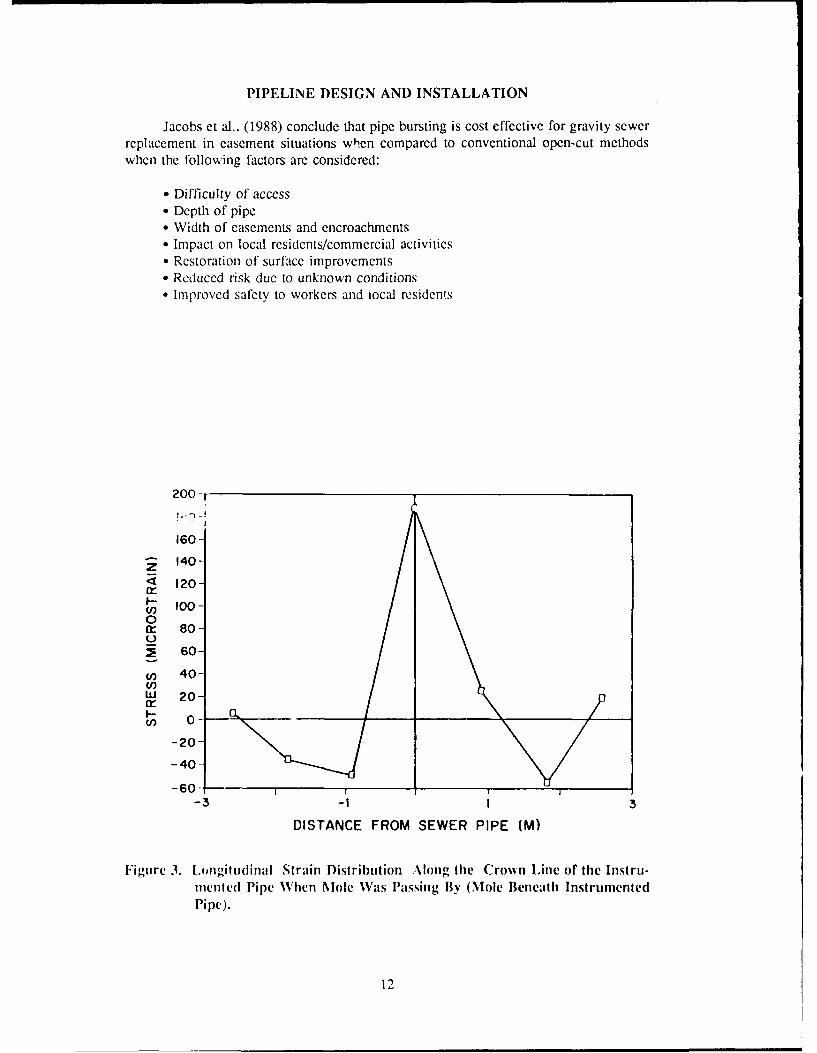
The results of these tests are detailed elsewhere (Briassoulis et al., 1989) and willonly be summarized here. Stress induced on the adjacent pipe produced only smallstrains, with the maximum strain above the impact mole's path being 200. Figure 3shows the longitudinal strain distribution along the crown line of the instrumented pipeas the mole was passing by. The mole was beneath the instrumented pipe. The resultswere found to be not significant. Maximum strain was developed at the crown nf theinstrumented pipe just above the sewer pipe. This is an example of classic straindistribution for a beam on an elastic foundation.
Soil displacements measured at different elevations above the sewer pipe as thcmole was passing by are shown in Figure 4. The maximum soil displacement was 0.00)
9

PIPELINE DESIGN AND INSTALLATION
inch at 16 inches above the sewer pipe. This compares to an increase of pipe radius of1 inch and an even larger expansion of the surrounding soil by the 10-inch diameter mole.Soil deformation in this test was essentially plastic.
Deformation of the new pipe may also pose a problem. Deformation of the newpolyethylene pipe is shown in Figure 5 with a maximum deformation of 2.5 percentchange of pipe diameter. A second test conducted 6 months later showed the magnitudeof deflection had increased to 4.5 percent, which is almost at the recommended acceptabledeformation of 5 percent (8-inch SDR 17 pipe).
A subsequent test of deformation after one year indicated that the vertical deflectionincreased a small amount, whereas the horizontal deflection decreased slightly. Thedecrease in horizontal deflection may be due to the soil recovering and sealing completelyaround the pipe. The net result is that deflection is remaining less than 5 percent of theoriginal diameter.
Vibrations were also noted as a potential problem. Vibrations directly over the pipewere found to be significant. The maximum vertical peak particle velocity reached 0.54in./s when the mole was beneath the array of geophones (Briassoulis et al. 1989), butdamped out quickly (0.06 in./s) at the 9-foot distance from the mole path centerline.
The results from U.S. Army and British tests were compared (Briassoulis et al,1989) and were shown to be comparable to vibrations induced by jackhammers. Figure6 shows a comparison between maximum PPV (Peak Particle Velocity) due to the impactmole and due to jack hammers and trucks. Thus, care should be exercised in locating andprotecting (e.g., by excavating and removing the soil between the mole and the criticalobject) utilities and structures sensitive to vibration.
The conclusion is that, with regard to vibration effects, the PIM technique shouldnot be considered as more damaging compared to other alternatives such as excavationusing jack hammers, or to usual sources of vibration like trucks, except for buried pipesand archeological objects located close to the operating mole. Vibrations appear todampen out quickly.
At Fort Belvoir, the use Df the mole technology resulted in minimal surfacedisruptions. The retaining wall and fence were not affected by the construction and trafficwas maintained at all times.
Economics
The Central Contra Costa Sanitary District (CCCSD) is one of the leading users ofPIM technology in the U.S. with demonstrations of several thousand linear feet during1987-1989 at a number of sites and information from their experience (Decker andLarson, 1988: Jacobs et al., 1988) has expanded the available limited data base.
Cost figures from the CCCSD (Decker and Larson, 1988; Jacobs et al., 1988)experience for 8 different runs ranged from $51 to $83/ft in 1987 and from $69 to $86/ftduring 1988 as approximately 7000 feet of sewer was upsized from 6 to 7.5 inch
10

PIPELINE INSERTION METHOD
diameter. Runs were made through a variety of terrains and soils, predominantly adobeclays which are very dense and difficult to compact. The runs were all in easements,of!tl extensivel% vegetated and steep. Overall savings using the tccnology w ati dat 6, 11, 15, 16, 28, 28, 44, and -42 percent for each of the 8 runs. It must be noted thatthe negative savings value was tbr a ni made across a golf course.
CCCSD continued the use of PIM technology during 1989 with their mos:challenging applications to date (Kurasaki, 1989). For example, one run was at a depthof 20 feet, another within 12 feet of a swimming pool, a third ran 4 feet from a home, arun under telephone ducts in pea gravel, through a schoolyard with disruptions, and a 700foot run on a steep hillside. Contract cost figures ranged from $82 to $99/linear foot withapproximately 3300 feet of 6 inch main replaced with 8 inch main at an average cost ofS94/foot. Overall costs to the sanitary district were approximately $102/foot whichincluded their cnstruction management time, field time, fence removal and repair, andsimilar contingencies. They (Kurasaki, 1989) again found the method to be morecost-effective than open-trench operations for the selected sites.
Using the PIM method, replacing 600 feet of cast iron requires a little more than175 square feet of repaving, as opposed to nearly 14(X) square feet of repaving requiredby direct burial. That's due to the two major excavations and the small access pits aredug to expose each service connection to allow customers to be tied into the new main.
Lessons-Learned
Lessons-learned from CCSD (Jacobs et al., 1988) experience have established thefollowing minimum specifications for future pipe bursting projects:
" Use of fusion welded saddles for service lateral reconnection
" Removal of all internal butt fusion weld beads
* Repair or correction of all major low spots in existing pipe prior to pipe burstingoperation
" Minimum cover of 3 feet in easements and 5 feet in streets
" Final inspection to include low pressure air test, deflection test wilh 95 percentmandrel, and CCFV inspection
* One year w arranty in installation and materials with deflection test at end ofwarranty period
They also noted short sags (less than 10 feel) appeared to be corrected Ly thelonger length of the pneumatic burster.
11
PIPELINE DESIGN AND INSTALLATION
Jacobs et al.. (1988) conclude that pipe bursting is cost effective for gravity sewerreplacement in easement situations when compared to conventional open-cut methodswhen the following factors are considered:
" Difficulty of access" Depth of pipe* Width of easements and encroachments" Impact on local residents/commercial activities" Restoration of surface improvements" Reduced risk due to unknown conditions" Improved safety to workers and tocal residents
200
160-
140-
120-in- 100-~oo
0cr 80-
2 60-
(n 40"(n)W 20-
_20(n 0 -- 20 -
-40-
-60 - I I I-3 -I I 3
DISTANCE FROM SEWER PIPE (M)
Figure 3. Longitudinal Strain Distribution Along the Crown Line of the Instru-mented Pipe When Mole Was Passing By (Mole Beneath InstrumentedPipe).
12

PIPELINE INSERTION METHOD
MOLE PASSES BY EACH TRANSDUCER AT T 0
1.4-1.341C
-. 1.2
_ .11.0-
Z0.9w
M 0.8
Ej0.94-
03
Id0.3
S0.1 LO UFC-0.0
-06NALAN VERTICAL DAEE 1AG-0.9 ECN TS-0.8
0.0 0. S04C.80OND0 .0.TIME "ORIZPUL MN
Figre5 eomto fIsre oythln ieAtrIsalto(Dfrato.s4litia)
W 0.3FIRS T13

PIPFI INE DESIGN AND INSTALLATION
3162
U)(I) IMPACT MODE (E)
,- FTRUCKS
I.-I
31.61
10.0
t.J
TN IMPACT MODE (F)3.2W_j JACK HAMMERS
X 03
CL-0.1 -1I
0,25 0.63 1.58 398 10100 25.12 63.10 158.49
DISTANCE (M)
Figure 6. Comparison of Attenuation Curves for Jack Hammer and Trucksand PIM Technique Tests. E = England, FB = Fort Belvoir.
Summary
PIM technology is gaining acceptance in the U.S. as a method for rehabilitating andupsizing sewer lines. Experience is being gained for optimal application of thetechnology and its effect on the surrounding soils.
References
lriassoulis. D., Maloney, S.W., and S.C. Sweeney, 1989. "Static and Dynamic Effects of the Pipe InsertionMachine Technique," Technical Manuscript N-89/07/ADA207745, U.S. Army Constniction
Engineering Research Laboratory.
Decker, C. and J. Larson, 1988. "California Sewer Replacement Experience using Pipe Bursting (PIM)
Technology," Proc. NO-DIG 88.
Jacobs, E., J. Larson, and C. Decker, 1988. "Addendum to California Sewer Replacement Experience UsingPIM Pipe Bursting Technology," Unpublished.
Kurasaki, Joye, 1989. CCCSD, Personal Communication, 8 November.
Maloney, S.W., 1989. "In-Place Replacement of Underground Pipes," in Proc. First International Conferenceon Underground Infrastructure Research, American Water Works Association Research Foundation,Denver CO.
Maloney, S.W. and D. Briassoulis, 1988. "Wastewater Collection System Rehabilitation Techniques for Arm\;nstallations," U.S. Army Construction Engineering Research Laboratory Technical Report
N-88/25/ADA203330. Champaign, IL.
14

USACERL DISTRIBUTION
Chief of Enjgineers USA Japurii (USARJ) WESTCOMATTN: CF ' ItEli-LiI (2) ATT-N: DCSEN 96343 Fort Shaflr 96858AITrN: CEIEC2I-LI.P (2) AITN: HONSHU 96343 ATTN: DEH?1TN: ClEKD-L ATIN: DEH.Okina~a 96376 ATT'N: A.PEN-AATIN: CEUC-PATTN: CECW Amea Engineer. AEDC-Area Office SHAPE 09705,'N: CECWO0 Arnold Air Force Station, TN 37389 AITN: Infrastructure Branch, LANDA
ATTN! CECW-PATTN: CEiCW-RR 416thEnerCommad 60623 HQ USELCOM 09128A71"N: CEM\P ATTN: Facilities Engirner ATTrN. ECI 4f7-LOEATITN: CEMP-NMATT7N: CEMP-O US Miliary Academy 10996 Fort Belvoir, VA 22060AIN<: CENP-R AT-TNr Facilities Engineer A77N: Aumtrliso Liaison OfficerA'17N: CEMI1'-C ATTN: Dept of Geaographry & ATrN: Wane Rescource CenterA1TN: CEMP.E Environmental En"ro ATTN: Engr Suregic Studis CtuAlTN:- CERD ATTN: MAEN-A A77N: Topographic Engr CoetA TTN: Ul ,RD-U ATTN: CECC-RA, I1N: CERD-M AMC - Dir.. Inst., & Socs.AIN: CLRM AITN: DEH (23) CECRL, ATIN: Library 03755ATrN: DAEN-Z.CEArI*N: DAEN-Z.C1 DLAA1TN: DL-A-WI 22304 CEWES,A77N: .ibrairy 39180ATTN: DAEN-ZUMA FI:DALN-/CZ DNA ATrN: NADS 20305 HQ, XVII I Airborne Corps sad
Ft. Bragg 283(Y7CEO ISC FORSCOM (28) A77N: AFZA-DEH-EE
AfTN. CEIISC.ZC 22060 FORSCOM Engineer, ATTN: SptDet. 1501Afl'N OFT 111 79906 AT17N: Facilites Engineer Chamt APE, IL 61868AITN: C[JfSC-F 22060 3345 CESIDE, Stop 27A'ITN CEIISC1-r- 22060 HSC
Ft. Sam Houston AMC 78234 AMMARC 02172US Army Engincr Districts ATTN: HSLO-F ATrN: ORXMR-AF
AIN: Library (41) Fitzsimons AMC 80045 ATTN: DRX)sIR-WEAlaska 99506 ATTN: HSHO-DEH
A 1rN: NAPE N-Pt1. Walter R4eed AMC 20307 Norton AFB, CA 92409ATTN: Facilities Engineer ATTN: APRCE-MXI1)E
US Arny Engr Dioiion,ATTlN: Library (13) INSCOM - Ci. bril. Div. Tyndall AFB, FL 32403
Ft Belvoim VA 22060 AFESC/EngSirering & Serice LabUS Army Eupe ATT'N: Engr & Hog Div
ODCS/Engincer 09014 Vint Hill Farms Station 22186 NAVFACAT-TN: AEAENFE ATIN: lAV-DEH ATTN: DivisarnOffices (11)ATITN: AEAEN-ODCS ATTN: FacilitiesEngrCond (9)
V Corps USA AMCCOM 61299 ATrN: Naval Public Works Center (9)ATTN: DEH4 (11) ATrN: Library ATTN: Naval Civil Engr Lab 93043 (3)
VII Corps ATTN: AMSMC-RI ATTN: Naval Constr Battalionr Ca 93043ATTN: DEH (15)
21st Suipport Comrmandl US Arry Engr Activity, CA Engineering Societies LibraryATTN: DEH (12) AITN: DEH New York, N4Y 10017
USA Berlin Camecron, Station (3) 23314
ATTN: DEll (9) Fort Lesley J. McNair 20319 National Guad Burviau 20310Allied Comtrmand Europe (ACE) Fort Meyer 22211 Installation Division
ATTN: ACSGEB 09703ATTN: Siffl11/Engiuwer 09705 Military Traffic Mgmt Creminand US overnment Printing Office 20401
USASETAF Falls Church 20315 Receiving/epostory Section (2)ATTN: AESE-EN-D 09613 Oakland Army Base 94626ATTN: ACSEN 09029 Bayonne (Y7002 US Arnty Env. Hygrews AgencyATTIN: AESSE-VE 09029 Sunany Point MOT 28461 ATTN: HSHB.ME 21010
fit USA, Korea NARADCOM, ATTN: DRDNA-F 01760 American Public Works Association 6D637
ATTN: DElI (19)TARCOM. Fac. Div. 4SD90 Nat'l Istitute of Stanrdsti & Tech 2D899
ROKIUS Combined Forces Command 96205ATT N: EUSAIOIC-CFCEmtgr TRADOC (19) Defense Technical Inc. Center 22304
HQ. TRADOC, ATTN: ATE24-DEH 23651 ATTN: DTIC-FAB (2)Ft. Leonard Wood, MO 65473 AIN: DEH
ATIN: ATZA-TE-SWATTN: Canadian Liaison Officer TSARCOM, ATTN: STSAS-F 63120 325ATN: Gerrmani Liaison Staff 11AI
ATTN: Biritish Liaison Officer USAISA'fN: Allied Liaison Office Fort Haacmue 85613ATTN: Frencht Liaison Officer ATrN: Facilities Engineer (3)
Fort Ritchtie 21719