review of polyarylacetylene matrices for thin-walled … · report ssd-tr-89-75 review of...
TRANSCRIPT

REPORT SSD-TR-89-75
Review of Polyarylacetylene Matricesfor Thin-Walled Composites
IN
IPrepared by
W T BARRY. C. A. GAULIN, and R. W KOBAYASHIMaterials Sciences Laboratory
Laboratory OperationsThe Aerospace Crration
El Segundo, CA 90245
25 September 1989
Prepared for
SPACE SYSTEMS DIVISIONAIR FORCE SYSTEMS COMMAND
Los Angeles Air Force BaseP . Box 92960
Los Angeles, CA 90009-2960
APPROVED FOR PUBLIC RELEASE;DISTRIBUTION UNLIMITED
This report was submitted by The Aerospace Corporation, El Segundo, CA
90245, under Contract No. F04701-85-C-0086 with the Space Systems Division,
P.O. Box 92960, Los Angeles, CA 90009-2960. It was reviewed and approved
for The Aerospace Corporation by R. W. Fillers, Director, Materials
Sciences Laboratory. Paul Propp was the project officer for the Mission-
Oriented Investigation and Experimentation (MOIE) program.
This report has been reviewed by the Public Affairs Office (PAS) and
is releasable to the National Technical Information Service (NTIS). At
NTIS, it will be available to the general public, including foreign
nationals.
This technical report has been reviewed and is approved for
publication. Publication of this report does not constitute Air Force
approval of the report's findings or conclusions. It is published only for
the exchange and stimulation of ideas.
PAUL PROPP, AF MATE S LAB WtO, USAF RAYM LEONG, MAJOR, USP'
MOIE Project Officer MOIE Program Manager
WRDC/WCO OL-AB AFSTC/WCO OL-AB

UNCLASSI FI EDSECURITY CLASSIFICATION OF THIS PAGE
REPORT DOCUMENTATION PAGEI& REPORT SECURITY CLASSIFICATION lb. RESTRICTIVE MARKINGSUnclassified
2L SECURITY CLASSIFICATION AUTHORITY 3. DISTRIBUTION/AVAILABILITY OF REPORT
2b. DECLASSIFICATION/DOWNGRADING SCHEDULE Approved for public release;distribution unlimited.
4. PERFORMING ORGANIZATION REPORT NUMBER(S) 5. MONITORING ORGANIZATION REPORT NUMBER(S)TR-0089( 4935-06)-I SSD-TR-89-75
6. NAME OF PERFORMING ORGANIZATION 6b. OFFICE SYMBOL 7a. NAME OF MONITORING ORGANIZATIONThe Aerospace Corporation (V applicable) Space Systems DivisionLaboratory Operations I
6c. ADDRESS (C4) $af adi ZIP Code) To. ADDRESS (CiO Stw% and ZIP Cod.eLos Angeles Air Force base
El Segundo, CA 90245 Los Angeles, CA 90009-2960
s. NAME OF FUNDING/SPONSORING 8b. OFFICE SYMBOL 9. PROCUREMENT INSTRUMENT IDENTIFICATION NUMBERORGANIZATION ( *plcAble) F04701-88-C-0089
8C. ADDRESS (CkA S and ZIP Code) 10. SOURCE OF FUNDING NUMBERSPRORAM ECP I TASK WORK UNITELEMENT NO. . NO. ACCESSION NO.
11. TITLE (ncluf Sfcwty CMafctmn)Review of Polyarylacetylene Matrices for Thin-Walled Composites
12 PERSONAL AUTHOR(S)Barry, W. T.; Gaulin, C. A.; and Kobayashi, R.. U.
13a. TYPE OF REPORT 13b. TME CVRED 14. DAZE OgRErORTgrr2%jw. D, 15. WCUI
FROM ____TO WSI .pem~16. SUPPLEMENTARY NOTATION.
17 COSAT CODES 18 SUBJECT TERMS (Conckxu on revrse it neceary ad lkwoy by bloc* nimt)Resins
FIELD GROUP SUe-GROUP Carbonization
V ~ I1 ABSTRACT (Coi~nue on rew Inocmswya wu vit'by block sanev
Polyarylacetylenes (PAAs) have been successfully employed over the past fifteen years asmatrices in the fabrication of thin wall carbon-carbon composites. Because of the proprie-tary nature of the early polymer, Its exact composition was not known. Recent Interest Inhigh performance thermal protection systems prompted a detailed reinvestigation of thesematerials. A brief review of the chemistry of the PAAs involved is discussed in light of ourcurrent experiences. The studies reaffirm our belief that these resins are prime candidatesfor carbon-carbon matrices and offer advantages in fabricability over currently used resins
0/
20. DISTRIBUTION/AVAILABU'Y OF ABSTRACT 21. ABSTRACT SECURITY CLASSIFICATION
UNCLASSIFIED/UNLIMITED [ SAME AS RPT E] OTIC USERS Unclassified
22. NAME OF RESPONSIBLE INDIVIDUAL 22b. TELEPHONE (include Are Code) 220. OFFICE SYMBOL
DD FORM 1473, 84 MAR 83 APR edion may be used unU exlhatsd. SECURITY CLASSIFICATION OF THIS PAGE
A ofedmm MAA UNCLASSIFIED

PREFACE
The authors would like to thank C. E. Williams and J. A. Noblet for
their technical assistance and Dr. G. S. Hellick for his many helpful sug-
gestions.
071C
Aooession For
NTIS GRA&IDTIC TABUnaaaounc edJusti@i4l4io
fly
Di stribution/
Availability Cod"
D A vail and/or
Dist SpecilJ
a~~~ I Im~
CONTENTS
1. I T O U T O . . . . . . . . .. . . . . . . . . . . . . . . .
A. BaTckgon.................................................. 5
B. Current Status............................................ 7
II. CHEMISTRY...................................................... 9
III. CONCLUSIONS ................................................... 17
REFERENCES.......................................................... 19
FIGURES
1. Synthesis of PAA............................................... 6
*2. TGA in Argon of Basic PAA Resins ................................ 8
3. Processing Aids Under Investigation ............................. 11
4I. Melt-Viscogran................................................. 12
5. Differential Thermal Analysis (DTA) ............................. 12
6. Effect of Processing Aid on Char Yield .......................... 13
7. Scanning Electron Micrographs (1000x) of
Carbon-Carbon Composites....................................... 16

I. INTRODUCTION
This report summarizes work which was initiated about fifteen years
ago I and updates our work on the utilization of polyarylacetylenes (PAAs)
as matrix precursors for thin wall carbon-carbon composites.
A. BACKGROUND
The initial motivation for this study was to develop special carbon
composites for ballistic reentry vehicles related to penetration
strategies. Basically, all the material systems developed were predicated
on the well known capacity of carbon to absorb large quantities of energy
before vaporizing. Considerable attention was given to the development of
both 2-dimensional and 3-dimensional carbon shells of thin wall construe-
tion for potential reentry application. Most of the early processing
employed in the fabrication of the articles used either phenolic or
furfuryl resins as the initial matrix precursor. The particular applica-
tion addressed required the development of both special carbon fibers and a
technique for placing them in a particular- geometry, which required special
control over layer thickness, placement, and fiber density. To this end,
we restricted the yarn bundles to 1000 filaments and the twist to 1 per
inch. (Some twist was necessary in order to maintain yarn integrity.)
Details of the construction dictated filament winding as the preferred
fabrication technique.
With our filament design concept fixed, our next concern became a
suitable matrix resin with which to bind the material system together. Our
preference was for a resin which (1) can be wet-wound for ease of filament
winding, (2) has a high char yield, (3) cures by addition rather than con-
densation, and (4) requires minimal pressure and temperature for process-
ing. Fortuitously, at this time Jabloner et al. 2 at the Hercules Experi-
mental Station were developing high temperature molding compounds based on
PAAs (see Fig. 1). This was a rather short-lived venture on the part of
Hercules, but we succeeded in obtaining several hundred pounds of pre-
5

polymer before the pilot plant was shut down. This material, known as
HA-43, was stored under refrigeration and used in developmental studies
over nearly a decade without obvious signs of aging or deterioration.
NICKELCATALYST
InDIETHYNYLBENZENE IDEB)
CYCLOTRIMERIZATIONIII "PREPOLYMER'
-1 Il REINFORCEMENTS.
II / CURE (heat, pressure)
YNI
PAA POLYMER
Fig. 1. Synthesis of PAA
Details of the fabrication procedures used in these studies are given
in a report submitted to the Defense Nuclear Agency by Haveg Industries.3
Briefly summarized, individual yarns were dip-impregnated in a 33% HA-43
solution in methylethylketone and wound onto a graphite mandrel. Maximum
fiber packing (60-70%) and accurate placement was a requirement which ne-
cessitated a high winding tension. Because of this, no further, debulking
on cure was needed and simple vacuum bagging sufficed. Using a solution
for ease of application, however, has its penalities, and two to three
reimpregnations with HA-43 solution were necessary to bring the composites
up to acceptable densities. Carbonization was carried out to 8000C in a
female graphite holding fixture to prevent warpage. After final
densification, the composites were processed to a maximum temperature of
only 1850 0C and, as a consequence, virtually no graphitization of the
matrix occurred. This temperature limitation was imposed in order to
minimize particle growth in the special carbon fibers.
6
Practically all of the fabrication difficulties encountered ir the
early phases of this study were attributed to the poor mechanical proper-
ties of the fibers. As fiber development proceeded and the quality of the
fibers improved, so did the quality of the composites because adequate
winding tension could be applied with minimum fiber damage. Correction of
these early difficulties resulted in thin wall composites (100-120 mils)
which both met the technical requirements and provided adequate mechanical
properties. Although the details of the fabrication of these composites
are probably not germane to the fabrication of exit cones, this work demon-
strated the utility of PAA as a matrix precursor in thin wall carbon-carbon
composites.
B. CURRENT STATUS
After a brief hiatus, interest in polyarylacetylenes was reawakened
with the primary objective not the development of carbon-carbon composites
or exit cones, but the development of superior- ablative protection sys-
tems. Our preference for an organic matrix over a carbon matrix composite
was due to its lower thermal conductivity, superior mechanical properties
and, finally, ease and cost of fabrication. Because of their known high
char yield (Fig. 2), PAAs appeared to be likely candidates for this
study. To this end, we decided to reinvestigate the early work of
Jabloner,2 which had been directed toward molding compounds, and determine
the utility of the PAAs in advanced composite systems. It was only after
we had established the feasibility of this approach that we again turned
our attention to their use in thin wall carbon-carbon composites. Because
of the preliminary nature of this study, only a limited amount of data on
carbon-carbon composites is available. However, we thought it would be of
interest to the community to review the chemistry of PAAs and, in light of
our more recent experiences with these materials, comment on those aspects
of the chemistry that seem appropriate to the construction of thin wall
carbon-carbons.
--Sm m ~ m iNIImI
1.00 --- 0
0.98- ,- 2
0.96- 4
1- 0.94- 6 00.92- \8
< 0.90 - 10=) " ,,I-
0.88- 12 Z
0.862 1 4
0.8 0.
0.84 ' " 163
0.82 18
0.80 ] I I 200 100 200 300 400 500 600 700 800 900 1000
TEMPERATUREC
SAMPLE 1: 100% META RESINSAMPLE 2: 75:25 BASE RESIN: PA (PHENYLACETYLENE)SAMPLE 3: HA-43 NEAT RESINHEATING RATE: 4C /min GAS FLOW RATE: 100 cc/Min
Fig. 2. TGA in Argon of Basic PAA Resins
8
1I. CHEMISTRY
Most of the monomeriediethynyl benzene used in this study was synthe-
sized by the method of Hay 4 in which commercial divinylbenzene (DVB),
consisting of a mixture of meta and para isomers [with meta and para ethyl-
vinyl benzenes (EVB) as a major impurity] are treated with bromine in chlo-
roform solution at OC. Most of the 1,4 bis dibromo ethyl benzene
(p-BDBEB) compound precipitates out and after filtration leaves a solution
of the 1,3-bis 1,2 dibromo ethyl benzene isomer (m-BDBEB), and meta and
para ethyl 1,2 dibromo ethyl benzene (p-EDBEB) as impurities. After strip-
ping off the chloroform, the dibromo ethyl (EDBEB) compounds are separated
from the m-BDBEB using a thin film evaporator. The residual m-BDBEB is
then dehydrohalogenated in tetrahydrofuran (THF) using potassium
t-butoxide. After filtering and stripping off the THF and t-butanol by-
product, the m-diethynyl benzene (m-DEB) is once distilled and used as is
in the preparation of prepolymer.
Although this procedure seems tedious, it is uncomplicated and the
yields are high. The commercial DVB (80%) assay that was earlier supplied
can, if there is sufficient demand, be obtained up to 95% DVB assay. Meta*
to para ratios, however, do appear to vary from batch to batch. If the
preference is for meta or para isomer-, the assay should be determined
before purchasing.
Our choice of the meta isomer was based upon tailoring the polymer for
improved mechanical properties and ease of processing. The monomer, a
liquid, is also easy to manipulate and purify, whereas the para diethynyl
benzene (p-DEB) isomer is a solid at 95'C and requires multiple recrystall-
izations for purification. We, therefore, made the decision to concentrate
on estabishing the capabilities of the m-DEB based polymers. Currently a
60/40 meta'para ratio of DEB is being examined.
'Private communication with C. Snoble of Dow Chemical, 1986.
9

Although a number of potential catalysts for the cyclotrimerization
reaction dre mentioned in the Jabloner patent, most of our experience has
been with the nickel acetylacetonate and triphenyl phosphine complex, which
we have found to be a practical system to handle. Prepolymerization was
carried out in either toluene or benzene solution--the latter being pre-
ferred for large batches since it limits the reaction temperature and pre-
vents a rate which is a runaway exotherm. More recently, the prepolymeri-
zation is performed in methyl ethyl ketone (MEK). MEK is preferred since
it limits the reaction temperature as does benzene, but is far less
toxic. In addition, the reaction time is decreased, presumably due to the
polar nature of this solvent. When sufficient reaction has occurred, the
solution is cooled to room temperature and the solvent stripped off using a
Roto-Vac. Flow characteristics of the prepolymer are then checked using a
flat parallel plate rheometer. Flow behavior provides an indication of
reproducibility of prepolymerization. Onset of flow below 100°C is
desirable for 100% meta-DEB and should decrease incrementally with
increased addition of phenylacetylene (PA).
Prepolymers have been prepared from pure m-DEB, copolymers of m-DEB
with phenyl acetylene (PA), and m-DEB blended with several processing aids
(Fig. 3) which have the effect of both plasticizing and reducing the cross-
link density of the system. Rheometer data for a number of these composi-
tions are shown in Fig. 4. From this it is evident that the pure meta
isomer requires substantial pressures for processing, whereas compositions
with processing aids are vacuum bag moldable at 800 - 900C. A further
major processing consideration is an exotherm. Differential thermal anal-
ysis (DTA) (Fig. 5) shows that the exotherm begins at about 110 0C and for
this reason we have been extremely careful to densify below this tempera-
ture and to maintain a long dwell time before increasing temperatures
through the exotherm zone. For thin wall composites this may not be neces-
sary and more processing studies are needed in this area. Processing aids
with terminal phenyl groups such as diphenyl butadiyne and II are quite
stable compounds and are not incorporated into the polymer structure until
10
cure temperatures of about 2000C are reached, at which a second lesser
exotherm can be expected. Just how and whether they are incorporated is
highly uncertain and requires further study since they do appear to be
viable processing aids.
An alternate processing aid is the addition of monomer. The monomer
acts as a plasticizer to the prepolymer in the processing. The monomer is
presumably cyclotrimerized into the polymer during cure due to residual
catalyst. Addition of monomer needs to be balanced between the required
plasticization and the increase in the exotherm resulting from the
cyclotrimerization reaction. Typically, 10% of the monomer is added.
I REF.5
1, 3-bis (3-ethynyl phenoxy) BENZENE (BEPB)
II ~ REF. 6
1, 3-bis [3-(phenylethynyl) phenoxy] BENZENE (BPE PB)
III ~ REF. 5
1, 3-bis (3-ethynyl phenoxy) 4-DIPHENYL SULFIDE (BEPDPS)
Fig. 3. Processing Aids Under Investigation
11
0-m*OE PA
I 1 100 02 75 2Sso
so
3 63 37
4 A
-40 75/25 m-DEB/PA BEPB
ASO 20
3o 30
c CSO0 40
0 so 100 IsTEMPERATURE. *C
HEATG RATE S do/mmn
Fig. 4. Melt-Viscogram
4
3-
I
EAT Of NIACTIOW S19 JiG 75/25 m-DEB/PA 20% 1
75/25 m-DEE/PA 20% 11
40 sO iN I"- no 240 M 340 40 440 4TEMPIRATIM. *C
Fig. 5. Differential Thermal Analysis (DTA)
12

Composite fabrication was carried out using conventional procedures.
The prepolymer was redissolved in MEK and used to dip-impregnate fabric
sheets. After vacuum bagging, they were then either press molded or cured
in a high temperature autoclave in a nitrogen atmosphere. Pressures varied
from 400 psi for the pure m-DEB prepolymer, to atmospheric pressure for
those with processing aids. Postcuring has been carried out at 250°C,
based on the DTA data, but the upper limit for optimum properties has not
been established. Figure 6 shows the effect of the processing aids on char
yield. The influence of the oxygen in these molecules is evident, but the
yields are still very high, which implies that char yield can be traded off
for ease of fabrication of complex structures with a minimum weight loss
penalty.
TGA IN ARGON
1.00 I . i 1 I I 009.
0.96 - (,: :,., 2
0.96- 4
0.94 \\-- 6 (
3 0.92- -6W X
0.90- •, ,-10
0.66 8\ \ 12
L40.86 - 14 \ 14
0.64 - \ 16
0.62 . 1
0.80 - 20
0.78 - 220 100 200 300 400 SO0 600 700 800 900 1000
TEMPERATUREC
SAMPLE 1: 75:25 BASE RESINSAMPLE 2: 20% BEPB/75:25 NEAT RESINSAMPLE 3: 30% BEPBI75:25 NEAT RESINSAMPLE 4: 40% BEPB/7S:25 NEAT RESIN
Fig. 6. Effect of Processing Aid on Char Yield
13

Preliminary carbonization studies have been started on the 75/25 meta-
diethynyl benzene copolymer for the purpose of determining residual mechan-
ical properties after exposure to moderate ablation conditions. It was not
our intention to redensify these composites, therefore the data is indica-
tive of only the first step in the carbonization cycle carried out at
1200 0 C (see Tables 1 and 2). Each mecharnical datum represents an average
of three tests. Resin content, fiber volume, and postcured porasity were
all calculated based on material balance and final detnsity. Carbonized
porosity and density were determined by mercury porosimetry. The choice of
T-300 reinforcement for the PAA composites was determined by structural
requirements. FM 5064, a commercial carbon phenolic widely used as a
carbon-carbon precursor, is shown for comparison of carbonization effi-
ciency. We used flexural strength as the primary criterion for strength
retention since this is a matrix dominated property. From this limited
data it appears that the PAA composites retain substantial strength after a
single carbonization. The use of particulate fillers in this system is
also probably unnecessary and merely complicates processing and quality
control.
An area of interest to carbon-carbon (C-C) applications is that of
graphitization of the resin. Although our, earlier studies using HA-43 did
not require us to graphitize and our current applications do not either, we
Table 1. Physical Properties of As-Cured and Carbonized Composites
BEFORE CARBONIZATION (post-cwed) CAONIZED
RESIN (+ ) FIER DENSITY POROSITY CHAR DENSITY POROSITYCOMPOSITE CONTENT CONTENT (0/cc) M YIEtD (00 MW1(MI) % 001 % (M(WO)
T 3001PAA 29(40) 60 1.56 3.9 9561 1.02 8.0
T 300PMIP-33 10 30(40) 60 1.56 2.6 95.6 1.65 9.1
CM/ON/PHENOIx 130 TOO 1.4 5.5 64.6 1.56 18.7(FM 504)
14
Table 2. Mechanical Properties of As-Cured and Carbonized Composites
BEFORE CARBONIZATION (post-cifd) CARBONIZED
TENSILE TENSILE FLEXURAL FLEXURAL FLEXURAL FLEXURALCOMPOSITE STRENGTH MODULUS STRENGTH MODULUS STRENGTH MODULUS
(PSI) (MSI) (PSI) (MSI) (PSI) (0SI)
T 300/PAA 70.580 8.69 53.760 8.26 21.110 8.47
T 300IPAA/P.33 10% 70.830 7.69 33.120 7.15 23.380 6.56
CARmONIPHENOLC 19.060 1.51 25.220 1.96 9.900 1.68(FM 5W64)
conducted a preliminary study of graphitization to 2400 0C of two
composites - one with pure meta isomer, the other with a 75.25 blend.
Based on limited micrographic evidence, we concluded that more extensive
ordering and crystal growth appeared to have occurred in the 75/25
specimen. We reasoned that the reduction ir, crosslink density in the 75s25
copolymer was responsible for greater- ease in rearrangement of the carbon
skeletal structure to the crystalline form. However, since that initial
study, Binegar, et al. 7 have examined many more specimens, including those
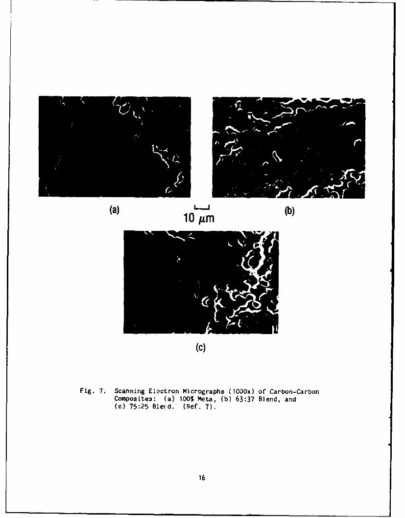
from 63/37 m-DEB/PA resin blend. Their scanning electron micrographs of
the three resin systems, heat treated to 2700°C, are shown in Fig. 7.
These specimens were xenon-ion-etched to enhance their microstructural
features. It is clear that the formation of graphitic structure, as
evidenced by regions of lamellar microstructure, is comparable in all three
specimens, and that the variations in crosslink density over their range of
compositions had no major influence on the graphitization process. It
should be noted that resins, in contrast to petroleum and coal-tar pitches,
show only limited graphitization in the interstices of C-C composites. In
bulk, they show no measurable graphitization. It remains to be determined
if the graphitizability of the PAA resins differs from that of phenolic and
other state-of-the-art resins.
15
Llow
((b)
Fig. 7. Scanning Electron Micrographs (1000x) of' Carbon-CarbonComposites: (a) 100% Meta, (b) 63:37 Blend, and(c) 75:25 Bleud. (Ref. 7).
16

III. CONCLUSIONS
Our study of PAAs resulted in the following conclusions:
1. The very high char yields of PAA resins appear to lend themselvesto the fabrication of thin wall carbon-carbon composites. In thepast, composites were produced successfully with HA-43 resinusing a solution wet-winding procedure.
2. Conventional processing techniques, prepregging, vacuum bagging,press, and autoclave molding, have been demonstrated. Furtherrefinements in processing and curing will be necessary whenlarger quantities of monomer become available.
3. Vacuum bag or low pressure molding of large or complicated shapesis achievable using processing aids such as BEPB with only asmall reduction in char yield.
4. There is no difference in graphitizability of various copolymersof meta-diethynyl benzene with phenylacetylene.
17
REFERENCES
1. Ketterer, M. E., Manufacturing Technology for Carbon Fiber ProductionProcess (Tantalum Carbide-Loaded Fiber), AFWAL-TR-84-4017, CelaneseResearch Co. (Feb. 1984).
2. Jabloner, H., U.S. Patent 4,070,333 January (1978).
3. Carbon-Carbon Composites for Protective Shielding, Haveg Corp., Tech.Report-2274-78, 19 July 1978, DNA Contract No. DNA-001-77-C-OO56 (Un-classified).
4. Hay, A. S., "Preparation of m- and p- Diethynyl Benzenes," J.O.C. 25637-38 (1960).
5. Harrision, J. J., et. al., "Low Cost Route to Acetylene TerminatedResins," Am. Chem. Soc., Polymer Preprints, ?3, (2); 189-90 (1982).
6. Arnold, F., et. al., "The Synthesis of Novel Monomers Containing Aryland Aryloxy-Ethynyl Groups," Am. Chem. Soc., Polymer Preprints 26 (1),136-37 (April 1985).
7. G. A. Binegar, J. A. Noblet, R. D. Zaldivar, P. M. Sheaffer and G. S.Rellick, "Effect of Heat Treatment on Microstructure and FlexuralProperties of Unidirectional Carbon-Carbon Composites," presented atthe 13th Annual Conference on Composites and Structures, Cocoa Beach,FL (18-21 January 1989).
19
LABORATORY OPERATIONS
The Aerospace Corporation functions as an "architect-engineer" for
national security projects, specializing in advanced military space systems.
Providing research support, the corporation's Laboratory Operations conducts
experimental and theoretical investigations that focus on the application of
scientific and technical advances to such systems. Vital to the success of
these investigations is the technical staff's wide-ranging expertise and its
ability to stay current with new developments. This expertise is enhanced by
a research program aimed at dealing with the many problem associated with
rapidly evolving space systems. Contributing their capabilities to the
research effort are these individual laboratories:
Aerophysics Laboratory: Launch vehicle and reentry fluid mechanics, heat
transfer and flight dynamics; chemical and electric propulsion, propellantchemistry, chemical dynamics, environmental chemistry, trace detection;spacecraft structural mechanics, contamination, thermal and structuralcontrol; high temperature thermoechanics, gas kinetics and radiation; cw andpulsed chemical and excimer laser development including chemical kinetics,spectroscopy, optical resonators, beam control, atmospheric propagation, lasereffects and countermeasures.
Chemistry and Physics Laboratory: Atmospheric chemical reactions,atmospheric optics, light scattering, state-specific chemical reactions andradiative signatures of missile pluses, sensor out-of-fleld-of-vlew rejection,applied laser spectroscopy, laser chemistry, laser optoelectronics, solar cellphysics, battery electrochemistry, space vacuum and radiation effects on
materials, lubrication and surface phenomena, thersionic emission, photo-sensitive materials and detectors, atomic frequency standards, andenvironmental chemistry.
Computer Science Laboratory: Program verification, program translation,performance-sensitive system design, distributed architectures for spacebornecomputers, fault-tolerant computer systems, artificial intelligence, micro-electronics applications, communication protocols, and computer security.
Electronics Research Laboratory: Hicroelectronics, solid-state devicephysics, compound semiconductors, radiation hardening; electro-optics, quantumelectronics, solid-state lasers, optical propagation and comnications;microwave semiconductor devices, microwave/millimeter wave measurements,diagnostics and radiometry, microwave/millimeter wave thermionic devices;atomic time and frequency standards; antennas, rf systems, electromagneticpropagation phenomena, space communication systems.
Materials Sciences Laboratory: Development of new materials: metals,alloys, ceramics, polymers and their composites, and new forms of carbon; non-destructive evaluation, component failure analysis and reliability; fracturemechanics and stress corrosion; analysis and evaluation of materials atcryogenic and elevated temperatures as well as in space and enemy-inducedenvironments.
Space Sciences Laboratory: Magnetospheric, auroral and cosmic rayphysics, wave-particle interactions, magnetospheric plasma waves; atmosphericand ionospheric physics, density and composition of the upper atmosphere.remote sensing using atmospheric radiation; solar physics, infrared astronomy,infrared signature analysis; effects of solar activity, magnetic storms and
nuclear explosions on the earth's atmosphere, Ionosphere and magnetosphere;effects of electromagnetic and particulate radiations on space systems; spaceinstrumentation.