review of practices for cleaning and sanitation of … machine...review of practices for cleaning...
TRANSCRIPT

REVIEW OF PRACTICES FOR CLEANING AND SANITATION OF MILKING
MACHINES Douglas J. Reinemann, Grea M.V.H. Wolters, Pierre Billon, Ole Lind, and Morten Dam Rasmussen
Introduction The fundamental performance requirement a cleaning regime for milk handling equipment is that the bacterial quality of milk is not substantially reduced between the time of harvest and removal from the farm. Cleaning of milk handling equipment is accomplished by a combination of chemical, thermal and physical processes which when combined have a minimum reaction time to be effective. A cleaning failure can result from a failure in any one of these processes. Any one of these factors can be intensified to make up for lack in another, up to a point. For example, a cleaning failure will result if cleaning solutions are not adequately distributed to all parts of the milking system. If little or no cleaning solution contacts a surface, the chemical and thermal actions cannot take place.
The constituents of the cleaning and sanitizing solutions provide chemical cleaning action. Heating the cleaning or sanitizing solutions before circulation provides thermal energy. Heat can also be added through heat exchangers in the cleaning flow circuit. Mechanical energy is produced by the turbulent flow of solutions through pipes and equipment with relatively small cross section. In components with large cross section and/or volume spraying solutions onto product contact surfaces produces mechanical action. It is common to increase chemical concentrations in situations where mechanical or thermal energy is limited.
Milking machines are usually cleaned at least twice and sometimes three times per day, corresponding with the milking frequency of the herd. Milking machines must be cleaned more frequently than equipment in diary plants because of the increased soil load and greater bacterial load resulting from handling a non-pasteurized product.
System Design and Mechanical Cleaning Processes Assuring an adequate mechanical cleaning action typically requires very little added cost but relies on the skill of the equipment installer. As milking machines become more complex the task of assuring adequate mechanical cleaning action in all parts of the milking machine becomes increasingly complex. There is increasing interest in cleaning systems that reduce energy consumption and minimize other environmental impacts. These overall goals can be aided by ensuring that the mechanical cleaning forces are used to their greatest advantage. Optimization of mechanical cleaning actions will result in reduced chemical and water usage.
Before any new milking machine is used, it should be thoroughly tested for both milking and cleaning performance. This is the responsibility of the milking machine supplier. The milking machine dealer should provide the dairy operator with instructions for operation of the milking machine in both the milking and cleaning mode. The results of a commission test should also be presented documenting that the milking machine is functional and with measurements of:
• Vacuum level at the regulator or vacuum gauge • Milking vacuum level (average vacuum in the claw at peak milk flow) • Pulsator rate and ratio with a commissioning check of each pulsator • Effective and Manual Reserve airflow • Air injector timing • Water flow rate thorough each milking unit during the wash cycle. • Recommended cycles for cleaning • Recommended chemical concentrations for each cycle
Milklines must be sloped between 0.5 and 2 percent (ISO 5707) toward the receiver jar to prevent slugging in milklines during milking. All pipelines, hoses and components must also be installed so that they will drain by gravity between cleaning cycles. Drainage is an important aspect of cleaning, because any standing water in

the system leads to mixing of cleaning solutions reducing their effectiveness and increases the risk of bacterial growth between milkings. All parts of the milking system (both sanitary and non-sanitary) should drain when the system is shut off. The milking system should be inspected for any pipes, hoses, fittings and equipment that do not drain after the system is shut down.
The non-sanitary parts of the milking system (pulsator airline, back flush system, etc.) may also be a source of bacterial contamination. If milk quality tests indicate equipment cleaning and sanitation problems in the milking system and the source cannot be found in the milking units, hoses, milk line or receiver, a visual inspection of airlines and ancillary equipment is indicated. These non-sanitary parts of the system should be cleaned periodically as part of routine maintenance of the system. The seals and gaskets and all rubber goods should be changed at least annually. Aged rubber becomes porous and is very difficult to clean.
A cardinal rule for efficient and effective Clean-In-Place (CIP) system design is to keep pipe lengths and number of fittings to a minimum. This will reduce the installation and operational cost of the CIP system as well as improve both milking and cleaning performance. The receiver should be located in such a way that the number of bends and fittings in the milkline are kept to a minimum. The receiver should not be placed in a location that will interfere with movement of the operators during milking. The wash sink is generally located near the bulk tank inlet to facilitate piping to switch from the milking to cleaning configurations. The length of piping from the milk room to the parlor should be kept to a minimum to reduce cleaning water volume, heat loss during cleaning and difficulties controlling circulation.
Manual cleaning Simple milking machines such as bucket milkers are typically disassembled and cleaned by hand. Even in the most complex machines using circulation cleaning, however, there are still components that must be disassembled and cleaned by hand (e.g. components of valve assemblies). The source of the mechanical cleaning action is typically a brush used to remove milk soil deposits. The use of extended contact times (soaking parts in a sink) is also widely practiced for small components.
Spray Cleaning Bulk tanks and other large vessels that may by part of a milking machine (weigh jars or milk meters chambers) are cleaned by covering their inner surfaces with a sprayed sheet of water. It is generally more difficult to maintain surface temperatures in spraying operations than in pipe flow conditions. Mechanical action is also significantly reduced compared to circulation cleaning. The chemical concentrations and wash water temperatures are therefore of critical importance for successful spray cleaning.
Flooded Flow The milk transfer line (from the milk pump to the wash sink) is cleaned in a flooded condition with the milk pump providing the fluid velocity. Milking machines with milkline diameter less than 48 mm have used flooded flow to circulate cleaning solutions through milklines. Flooded flow is also encountered in components such as hoses milking units in which internal diameters are small. The desired flow velocity for flooded components is above 1.5 m/s.
Steady air admission The amount of water required to fully flood a milking system with very long and/or large diameter milklines becomes impractical. The power available to achieve adequate flow velocity is also limited with the equipment available as part of the milking machine. Air admission has been used to produce two-phase (air/water) flow and overcome these limitations. Steady air admission is practiced on some small diameter milklines (< 48 mm) to reduce the required water volume and increase flow velocities. Some milking units and milk meters are also designed to introduce steady air admission during cleaning. This steady air admission will improve mechanical cleaning action slightly but makes balancing water flow through units more difficult and increases the vacuum pump capacity required for cleaning.

Cycled Air Admission (air injectors) and Slug Flow Cycled air admission is commonly practiced on milking machines with milkline diameter 60 mm or greater. The objective in air-injected flow is to form a 'slug' of cleaning solution and move this slug around the entire pipeline. The slugs may vary from a few centimeters up to several meters in length. The area between the slugs contains a slower moving liquid film in the bottom of the pipe. The slug velocities developed with air injected two-phase flow can be 3 to 5 times higher, and the wall shear stress developed ten to twenty times higher than those in flooded CIP circuits. The contact time between the slug and pipe wall is significantly reduced, however.
Slug velocities of 7 to 10 m/s maximize the wall shear stress developed while minimizing the variation of shear stress along the pipe. The rate of air admission to the milkline should be controlled to achieve these slug velocities. Air admission rates above this maximum will result in reduced slug density and reduced mechanical cleaning action in the milkline. Methods for adjusting cycled air injection are presented by Reinemann et al (1997).
When cycled air admission is applied to the wash manifold, the pipes and components are alternately filled and emptied. This has been referred to as controlled flushing pulsation by Lind (1990). A study by Verheij and Wolters (1993) showed that increased system vacuum improved the removal of residual milk from milking units, milk meters and milklines in flooded systems during the pre-rinse process. If the filling and emptying of the manifold is not complete in each cycle, significant variation can occur in the flow components (Reinemann et al 1997), and should be avoided in large milking parlor systems.
The vacuum pump capacity for cleaning includes the normal air use of all components in operation during cleaning (about 30 L/min per milking unit) plus that used by steady or cycled air admission. The air required for air injectors used to create slug flow in milk lines is given in Table 1 (from ISO 5707). With proper system design and control strategies, the vacuum pump capacity required for cleaning most milking machines is less than the minimum recommended for milking. Additional vacuum pump capacity may be required on large systems using cycled air injection to multiple locations.
Although system designs vary considerably, common features of milking parlor CIP systems are shown in Figure 1. Cleaning solutions are transported from the wash vat through the sanitary parts of the system and back to the wash vat during the CIP process. Two-phase flow patterns are determined by the diameter of system components and water and air flow rates. Internal diameters range from 10 mm in short milk tubes to 98 mm or more in milklines and in excess of 150 mm in milk meters and recorder jars. Flow velocities and flow patterns therefore vary greatly in the different parts of the system. Air-injection is normally used to produce slug flow in milklines. The objectives and optimal control strategies for air and water admission to milking units and other components differ from those for the pipeline. Milking units are either flooded or alternately flooded and emptied. Large components such as some milk meters and recorder jars are generally cleaned with a spray or sheet of water over the interior surfaces.
Air Required for slug flow (l/min) for various system vacuum levels
Internal Diameter of Milk
line (mm) 40
kPa 45 kPa
50 kPa
38 326 299 272
48 521 477 434
60 814 746 678
73 1205 1104 1104
98 2171 1990 1809

Receiver
Wash Sink
Milkline
WashManifold
Wash Valve
MilkingUnit
Jetter
A1A2
ReceiverReceiver
Wash Sink
Milkline
WashManifold
Wash Valve
MilkingUnit
Jetter
A1A2
A3
Figure 1. Components of a cleaning system for a milking parlor. Cycled air injection may be introduced to the milkline at either A1 or A3 (but not both). If air is injected at A3 the wash valve is eliminated. Air may be injected to A2 in combination with either A1 or A3. This improves cleaning of components such as milk meters but complicates the task of achieving uniform flow distribution
In milking parlors, milking units are commonly attached to wash assemblies (jetters) fed from a wash manifold. This water-draw pipe network and jetters make up the wash manifold. Cycled air-injection may enter through the wash manifold, the milkline or both. When air is injected only through the wash manifold it is common to include a hose or pipe from the water draw line directly to the milkline. Air injection to the milkline may occur at the receiver (requiring a wash valve between the air injector and receiver) or at the far end of the milkline (with no wash valve in the milkline). Air and water are separated at the receiver jar. The air travels to the distribution tank and is removed from the system by the vacuum pump. Water is returned to the wash vat by the milk pump through the milk transfer line. If air injection is used the timing of the air injection cycle is critical to achieve the desired result.
Another strategy is to for installations without controlled air injection is to adjust the water volume in the wash sink so that the sink is emptied after flooding critical components in the milking machine. Air is then drawn into the wash lines. This air admission increases flow speeds as the cleaning solutions are removed from the system. This strategy becomes more difficult to control as the size of the milking installation increases.
Large variation in water flow between milking units can occur in milking parlors when no attempt is made to adjust the flow. The system vacuum, line diameter and length, and the lift from the wash sink determine the flow capacity of the wash manifold. Excessive flow through the first several units can drain the wash manifold resulting in little or no flow through units at the end of the line.
Milk pump capacity is often the limiting factor in CIP systems. The distribution of water flow between units should be as uniform as possible to make the most efficient use of water and air when cleaning milking equipment and to avoid exceeding the capacity of the milk pump. Field studies have indicated that 3 L/min is sufficient to clean most milking units and is the minimum recommended flow rate. While many units will clean at flow rates below this value, the risk of cleaning failure appears to be increased. Systems with milk meters or weigh jars require 4.5 to 6 L/min for effective cleaning. Strategically placed and sized flow

controllers or some other method should be used to ensure that the minimum flow rate is achieved in each milking unit and to achieve reasonable uniformity of flow across all units.
Thermal and Chemical Processes Cleaners are generally classified as either Acidic or Alkali compounds. The primary function of acidic compounds is to dissolve inorganic (mineral) deposits while alkali compounds are used primarily to dissolve organic deposits (fat and protein). A variety of other constituents are added to amplify the acid/alkali removal processes and to protect equipment surfaces from cleaning compounds. The activity of cleaning solutions generally increases with increasing temperature and chemical concentration, however excessive temperature can cause volatilization of some chemical constituents thus reducing effectiveness or cause proteins to denature and accelerate mineral deposition. Excessive chemical concentrations can lead to corrosion or other forms of damage to system components and to residues in the milk.
Water is the major constituent of almost all cleaning and sanitizing compounds. The presence of suspended solids, minerals or other dissolved constituents can have a significant influence on the efficacy of cleaning and sanitizing agents. In some cases water treatment to remove specific components such as iron and silicates may be the only option to achieve adequate cleaning and sanitation. Chemical concentrations can be increased to account for some components in water, such as hardness. It may be more economical to treat the water used for cleaning and sanitation rather that compensate by adding more chemical. The following table gives several calcification systems for water hardness.
International Units (mmol CaCo3 / Litre)
Hardness as ppm of CaCo3
German degrees of Hardness scale (°dH)
Soft < 1.6 <160 < 9
Slightly Hard 1.6 to 3.2 160 to 320 9 to 18
Hard 3.2 to 4.6 320 to 460 18 to 26
Very hard > 4.6 > 460 > 26
A Cleaning/Sanitizing regime is typically made up of the following chemical processes, some of which may be combined into a single step and some of which may contain several steps. The majority of the residual milk in the system should be removed before beginning the cleaning process by allowing components to drain. Passing compressed air or air under vacuum through system components may facilitate this process.
Water rinse A pre-rinse may be applied to remove residual milk clinging to surfaces and other easily soluble or suspended deposits. These rinses should not be circulated, but rather discarded after a single pass through the system. The temperature of the pre-rinse is usually between 38 C and 55 C. The lower limit is set above the melting point of butterfat. The upper limit has been specified in the belief that proteins may be ‘baked’ on to surfaces. A benefit of the initial rinse is to warm the equipment to reduce the temperature drop during the subsequent cycles. This benefit is marginal when the subsequent cycles are not started within 5 minutes after the rinse. Water rinses may also be applied between chemical cycles to remove residual cleaning chemicals so that mixing of incompatible chemicals will not occur. A Final Rinse may be applied to carry away soils suspended during the cleaning step and remove residual cleaning solutions.
Alkaline Detergent Alkaline detergents are used to remove organic soils such as milk fat and proteins. Detergents reduce the surface tension of water so that the solution can more effectively wet and penetrate soils that have adhered to surfaces. Detergents contain compounds to reduce the surface tension of the solution, saponify fats, peptize proteins and disperse and suspend these soils in solution. Most detergents have a working temperature range

between 43°C and 77°C; however there are also low temperature formulations available. The cleaning effectiveness of detergents improves as temperature is increased and as water hardness decreases. The detergent concentration must be adjusted to account for these factors as well as the presence of other elements such as iron or sulfur bacteria. The alkalinity of the solution to be circulated is typically in the range of 250 to 500 ppm of alkalinity (expressed as Na2O) for milking machines and 400 to 800 ppm of alkalinity for bulk milk storage tanks. The alkalinity of the solution will depend on the temperature of the wash solution, type of materials in the milking machine, and the ratio of the surface area cleaned to the volume of cleaning solution. Chlorine is often added to alkaline detergents as a peptizing agent to aid in protein removal and to improve the rinse-ability of the detergent. The Chlorine content ranges from 75 to 200 ppm of NaOCl for milking machines and 100 to 200 ppm of NaOCl for bulk milk storage tanks.
Acid Rinse An acid rinse cycle is performed to remove mineral deposits from water and milk. This may be a cold or warm rinse. The required frequency of acid rinse depends on the quality of the water used for cleaning. Acid rinse solutions typically have a pH 3.5 or less.
Acidified boiling water The acidified boiling water method is used in some parts of the world. An acid detergent is used at a temperature of at least 95 ° C. The wash solution makes a single pass through the system and is not circulated. Acid is added to the hot water during the first two minutes of the process. Hot water is passed through the system for an additional 5 to 7 minutes. The objective is to maintain all surfaces at a temperature above 77 C for at least 2 minutes. In this was disinfection is accomplished by the thermal action of the hot water without the use of chemical disinfectants. The chemical action of alkaline detergents is also replaced with intensified thermal action. It requires special equipment to achieve elevated water temperatures and milking system components that can withstand these high temperatures.
Disinfection Disinfection (or sanitizing) as it is commonly understood when applied to dairy process equipment, is the reduction of microorganisms to acceptably low numbers. Sanitizing differs from sterilization, which implies the destruction of all microbial life. Disinfectants are applied to surfaces that have already been cleaned to kill microorganisms that have survived the cleaning and/or equipment storage process. Residual soil deposits reduce the effectiveness of sanitation by providing incubation sites for microorganisms, protecting microorganisms from sanitizing agents, or reaction of organic matter with chemical disinfectants. Chlorine-based products are the most common form used for milk handling equipment on dairy farms. The range of microorganism killed by chlorine-based products is probably broader than that of any other approved disinfectant. Chlorine is effective against gram-positive and gram-negative bacteria and conditionally against certain viruses and spores. Bacteria, viruses, molds, yeasts, spores algae and protozoa are all inhibited to some degree.
Chlorine-based disinfectants are used at concentrations of 100 to 200 ppm of available chlorine. The most active and widely used chlorine compounds are hypochlorites of calcium (CaOCl) and sodium (NaOCl). Active chlorine reacts with and is inactivated by residual organic mater. Chlorine is easily volatilized during storage, especially if stored improperly, or during mixing of the product prior to use, especially if solutions are mixed at high temperature. Chlorine volatilization can cause significant reduction in the available chlorine in products and/or sanitizing solutions. Chlorine gas is formed when chlorine products are mixed with acid. This gas is dangerous if inhaled and is also corrosive to stainless steel. Care should be taken to ensure that chlorine and compounds are not mixed. Chlorine-based disinfectants are circulated immediately before milking to kill bacteria that have survived the cleaning process. Pre-milking disinfection may not be performed on machines that do not stand idle for more than several hours between the previous wash cycle and the subsequent milking, or when a disinfectant is combined with either the detergent wash or acid rinse cycles, or when water rinsing after each chemical treatment cycle is enforced.

Acid disinfectants are considered toxicologically safe and mineral removal and disinfection can be combined into one step with these products. Acid-anionic surfactants are mixtures of an acid, usually phosphoric with and anionic detergent. The range of bacteria killed by acid anionic surfactants includes vegetative cell of both gram-negative and gram-positive species; however, bacterial and fungal spores are resistant. The efficacy of acid disinfectants on individual organisms is dose dependant.
Organic acids such as acetic, lactic, proprionic, and formic are used most frequently. Acids neutralize alkalinity from detergents and prevent the formation of alkaline deposits on surfaces. Acid products are most effective on stainless steel surfaces or where contact time may be extended. The advantages of acids are that they are heat stable up to 100°C, they are relatively unaffected by the presence of organic matter; they are effective over a broad range of vegetative cells. The disadvantages of acids are high cost and corrosiveness to iron and some other materials.
Manual Cleaners Manual cleaners differ from the low foaming formulations designed for circulation cleaning. Manual cleaners typically contain more surfactants than circulation cleaners and are formulated to be effective at lower temperature.
Typical Cleaning Regimes The choice of which cleaning regime is used depends strongly by the habits and regulations of each country, the relative cost of energy for heating water, chemical cost and availability and effectiveness of the process. Farms with very small herds (less than 30 cows) tend to use a high degree of manual cleaning and disinfecting. This usually involves hand cleaning of some or all of the milk harvesting and storage equipment. Small to medium herds (30 to 500 cows) commonly use automatic washing equipment. This equipment will automatically mix the chemicals with the appropriate water volume and temperature and circulate these solutions through the milking machine. On large farms (1000 cows or more), an attendant may be present to mix chemical solutions and operate valves for circulation. The chemical processes described above are used in various combinations around the world.
• In the Netherlands, France and much of Europe the standard cleaning regime consists of: pre-rinse with warm water (35-45°C), combined alkaline detergent and disinfectant (8 -10 minutes), followed by a post-rinse with cold water. A similar regime is used with an acid solution once or two times a week or once a day depending on the hardness of the water.
• The most common routine in the US is a combination of: pre-rinse, alkaline detergent, acid rinse
(frequency depending on water hardness), and pre-milking disinfection.
• A practice used in New Zealand is an acidified boiling water wash (alternated periodically with alkaline detergent) followed by a cold water rinse.
• A conventional Danish procedure is composed of: pre-rinse, alkaline detergent, cold water rinse, acid rinse, and then a pure water rinse immediately before milking.
Cleaning Assessment Methods
Visual inspection Cleaning failures usually result in a visual buildup or residual film on some part of the milk harvesting or storage equipment. Some of these films have a characteristic appearance, which can help determine the cause of the cleaning failure. There are two broad categories of residual films: Organic films such as fat and protein, and inorganic films such as hard water minerals, iron, and silica. Discoloration of surfaces may also occur due to corrosion and/or pitting. Films containing fats are soft when wet and dry. Protein films are hard when wet or dry and have a light brown color (applesauce). Mineral films are hard when wet or dry and usually have a
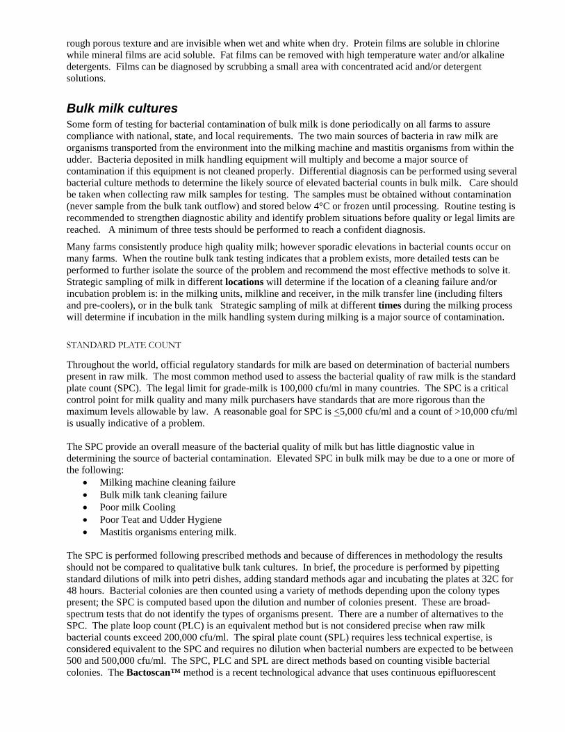
rough porous texture and are invisible when wet and white when dry. Protein films are soluble in chlorine while mineral films are acid soluble. Fat films can be removed with high temperature water and/or alkaline detergents. Films can be diagnosed by scrubbing a small area with concentrated acid and/or detergent solutions.
Bulk milk cultures Some form of testing for bacterial contamination of bulk milk is done periodically on all farms to assure compliance with national, state, and local requirements. The two main sources of bacteria in raw milk are organisms transported from the environment into the milking machine and mastitis organisms from within the udder. Bacteria deposited in milk handling equipment will multiply and become a major source of contamination if this equipment is not cleaned properly. Differential diagnosis can be performed using several bacterial culture methods to determine the likely source of elevated bacterial counts in bulk milk. Care should be taken when collecting raw milk samples for testing. The samples must be obtained without contamination (never sample from the bulk tank outflow) and stored below 4°C or frozen until processing. Routine testing is recommended to strengthen diagnostic ability and identify problem situations before quality or legal limits are reached. A minimum of three tests should be performed to reach a confident diagnosis.
Many farms consistently produce high quality milk; however sporadic elevations in bacterial counts occur on many farms. When the routine bulk tank testing indicates that a problem exists, more detailed tests can be performed to further isolate the source of the problem and recommend the most effective methods to solve it. Strategic sampling of milk in different locations will determine if the location of a cleaning failure and/or incubation problem is: in the milking units, milkline and receiver, in the milk transfer line (including filters and pre-coolers), or in the bulk tank Strategic sampling of milk at different times during the milking process will determine if incubation in the milk handling system during milking is a major source of contamination.
STANDARD PLATE COUNT
Throughout the world, official regulatory standards for milk are based on determination of bacterial numbers present in raw milk. The most common method used to assess the bacterial quality of raw milk is the standard plate count (SPC). The legal limit for grade-milk is 100,000 cfu/ml in many countries. The SPC is a critical control point for milk quality and many milk purchasers have standards that are more rigorous than the maximum levels allowable by law. A reasonable goal for SPC is <5,000 cfu/ml and a count of >10,000 cfu/ml is usually indicative of a problem. The SPC provide an overall measure of the bacterial quality of milk but has little diagnostic value in determining the source of bacterial contamination. Elevated SPC in bulk milk may be due to a one or more of the following:
• Milking machine cleaning failure • Bulk milk tank cleaning failure • Poor milk Cooling • Poor Teat and Udder Hygiene • Mastitis organisms entering milk.
The SPC is performed following prescribed methods and because of differences in methodology the results should not be compared to qualitative bulk tank cultures. In brief, the procedure is performed by pipetting standard dilutions of milk into petri dishes, adding standard methods agar and incubating the plates at 32C for 48 hours. Bacterial colonies are then counted using a variety of methods depending upon the colony types present; the SPC is computed based upon the dilution and number of colonies present. These are broad-spectrum tests that do not identify the types of organisms present. There are a number of alternatives to the SPC. The plate loop count (PLC) is an equivalent method but is not considered precise when raw milk bacterial counts exceed 200,000 cfu/ml. The spiral plate count (SPL) requires less technical expertise, is considered equivalent to the SPC and requires no dilution when bacterial numbers are expected to be between 500 and 500,000 cfu/ml. The SPC, PLC and SPL are direct methods based on counting visible bacterial colonies. The Bactoscan™ method is a recent technological advance that uses continuous epifluorescent

microscopy to count bacterial cells stained with acridine orange. Bactoscan™ has compared favorably to traditional bacteriologic methods and is considered to be less variable and more reproducible.
THERMODURIC BACTERIA COUNT
Another bulk milk test that provides diagnostic value is the thermoduric count or Laboratory Pasteurized Count (LPC). Thermoduric organisms are often related to spoilage of pasteurized milk. The LPC is a SPC performed on milk that has been heated to 145F (62.8C) and held for 30 minutes (low temperature-long time pasteurization). Typical mastitis causing organisms (including coliforms) do not survive pasteurization. Thermoduric bacteria may include Micrococcus, Microbacterium, Lactobacillus, Bacillus, Clostridium and occasional Streptococci. These of organisms will grow and multiply in the milk handling equipment if cleaning and sanitation procedures are inadequate. The LPC should be below 100 to 200 cfu/ml and a LPC below 10 cfu/ml indicates excellent equipment hygiene.
COLIFORM COUNT
The Coliform count provides an indication of both the effectiveness of cow preparation procedures during milking and the cleanliness of the cows’ environment as a major source of coliform bacteria in bulk tank milk is transportation of soil from the teats and udders into the milking machine. Coliforms can also incubate on residual films of milking equipment, however. Coliform counts are performed by culturing dilutions of raw milk on selective media such as violet red bile agar. The plates are incubated at 90F (32C) for 24 hours.
Coliform counts less than 10/ml indicate excellence in both pre-milking hygiene and equipment sanitation. Coliform counts must be less than 10/ml where raw milk may be sold to consumers. Poor milking hygiene usually results in coliform counts between 100 and 1000 with a commensurate rise in SPC and near normal LPC if the milking machine is clean. Coliform counts in excess of about 1000 suggest that bacterial growth is occurring on milk handling equipment. In cases of prolonged cleaning failure Coliform, SPC and LPC will be elevated due to coliforms and other bacteria growing in soil films in the milking machine.
MASTITIS ORGANISMS AND SPC
Bacteria in raw milk can come directly from the environment or originate as mastitis organisms. Bacterial “spikes” (defined as “transient sporadic increases in SPC values that exceeded a 95% confidence interval for mean SPC and were >10,000 cfu/ml”) have been associated with streptococci (primarily Strep uberis) and gram-negative organisms. Very high shedding has been documented for cows infected with S uberis mastitis and S agalactia. Sub-clinical mastitis problems should be considered when both the SCC and SPC are high. This situation is most common on small herds in which one or two shedding cows can have a significant influence on the bulk tank totals. In these instances the SCC and the SPC are generally both high and the causative organism should be apparent from a quantitative bulk tank culture.
System rinsing IDF (1984) describes a method of rinsing the milking machine to determine the effectiveness of the cleaning regime. The machine is rinsed with sterile water and samples assessed of the bacterial population in the rinse water. For this method the standard Plate must be <20,000 cfu/ml, thermoduric bacteria < 2,000 cfu/ml, Coliforms < 100 cfu/ml and psychrotrophs (such as Pseudomonas) <2,000 cfu/ml.
ATP Bioluminescence The results of bacterial test results are not available for two to three days after testing. Recent developments of ATP detection methods using a bioluminescence have been proposed as a rapid method for assessing the effectiveness of sanitation in the dairy industry. ATP bioluminescence is a rapid detection method suited for on-site sampling and takes less than five minutes to perform. ATP bioluminescence has the potential to be a useful tool to evaluate the effectiveness of cleaning procedures used on the milking machines.
The ATP method appears to be a more sensitive method to detect differences in cleaning effectiveness than bulk tank culture methods (Reinemann and Ruegg, 2000). There is considerable variation in the data

collected, however, and the method must be used carefully and with sufficient number of test to obtain meaningful results. The required sample size will depend on the skill of the user and the stability of the system being monitored. Care must be taken to avoid contaminating the inner surfaces of components as they are opened for swabbing. The variability in the ATP data can be reduced significantly by using the same measurement locations over time.
Environmental Issues There are several environmental issues that are beginning to influence cleaning practices in some parts of the world. The discharge of cleaning and disinfecting chemicals into the environment can be an issue for elements such as phosphorous and chlorine. There has been considerable work done on the development of enzymes as cleaners or additives to conventional cleaning solutions. Enzyme cleaners have had limited success and have not yet been widely adopted for milking machines. A critical factor in the success of enzyme cleaners appears to be matching the enzyme to the specific type of soil. This can be a limitation when soils are composed of a wide variety of substances. Enzyme cleaners must also operate in a narrow temperature and pH range to avoid deactivation, which can also be a limitation in many cleaning situations. The use of ozone as a disinfectant has been investigated to replace chlorine but in general have not reached the market yet.
The volume of water used for cleaning and discharged into the environment can be an issue in areas with water shortages. The energy used for heating and pumping water also has environmental implications. Several of the research publications cited in the bibliography report on various methods to reduce water volume, chemical volume and energy requirements for cleaning through efficient system design and control, reuse of cleaning solutions.
References Book, J.M., and D.J. Reinemann, 1994. New Ideas for Washing Pipelines. Proc. of the National Mastitis
Council Regional Meet. Pp 10-15.
Bramley AJ, Dodd FH, Mein GA and Bramley JA (1992) Milk Hygiene and Machine Milking. Machine Milking and Lactation. Insight Books, Huntington, VT.
British Standards Organization, 1982. BS5226, Cleaning of Milking Machines,.
Britt, J.S., F. Hartmann and D.J. Reinemann, 1997. Use of Microbiology and Strategic Sampling at strategic times to solve High Bacteria Count Problems in bulk Tank Milk. Proc. Ann. Meet. Natl. Mastitis council. 36:80-90.
Clegg and Cousins 1969. Cleaning of Milking Machines. Proceedings of the 1968 Symposium on Machine Milking, National Institute for Research in Dairying
Cousins and McKinnon, 1977. Cleaning and Disinfection. In Machine Milking. Published by the National Institute for Research in Dairying.
Guterbach, W.M., and P.E. Blackmer, 1984. Veterinary Interpretation of Bulk Tank Milk. Veterinary Clinics of North America: Large Animal Practice, Vol. 6, No. 2:257-268.
Grasshoff, A. and D.J. Reinemann, 1993. Zur Reinigung von Milchsammeleitungen mit Hilfe einer 2-Phasen Stroemung. Kieler Mischwirtshaftliche Forschungsberichte, 45, 205-234.
IDF 1984. Assessment of Bacterial Contamination of Pipeline Milking Installation. International Dairy Federation Doucment A-79, Brussels..
IDF 1982. Testing the Efficiency of Cleaning Units for Milking Installations. International Dairy Federation Document A-67, Brussels.
IDF, 1987. Hygienic Design of Dairy Processing Equipment. International Dairy Federation, Bulletin no 218, Brussels.
Lind, O., 1990. Cleaning-in-place (CIP) of the milking machine. Physical forces. In Proc. Seminar on Machine Milking and Mastitis, Aarhus, Denmark, Aug 6-8 1990. pp. 162-173.

Muljadi, A., D.J. Reinemann, and A.C.L. Wong, 1996. Air injected Clean-In-Place for milking systems: Development of a Study Method and Characterization of Chemical, Mechanical and Thermal Factors. ASAE paper No. 963019. American Society of Agricultural Engineers.
Murphy, S. 1997. Raw Milk Bacteria Tests: SPC, PI, LPC, and Coli – What do they mean to your farm? Proc. National Mastitis Council, Regional Meeting, Syracuse New York, 34-42.
Peebles, R.W., and D.J. Reinemann, 1995. Control Strategies to Reduce the Vacuum Pump Capacity Required for Cleaning Milking Systems. Paper No. 953274. Int. Meet. American Society of Agricultural Engineers, June 18-23, 1995, Chicago, Illinois
Reinemann, D.J., and P.L. Ruegg, 2000. An Investigation of ATP Bioluminescence and Quantitative Bulk Tank Cultures to Assess Cleanliness of Milking Machines. Paper No. 003009. ASAE Ann. Int. Meet., Milwaukee, Wisconsin, July 10-13.
Reinemann, D.J., R.W. Pebbles and G.A. Mein, 1997. Control Strategies for Milking Parlor Clean-In-Place Systems. Transactions of the ASAE Vol. 40 No 6. Pp. 1749-1753.
Reinemann, D.J., G.A. Mein, D.R.. Bray, D Reid and J.S Britt, 1997. Troubleshooting High Bacteria counts in Farm Milk. Proc. Ann. Meet. Natl. Mastitis Council, 36:16-19.
Reinemann, D.J., 1996. Technical Design and assessment of tube equipment using two-phase flow for cleaning and disinfection. Zbl. Hyg. International Journal of Hygiene and Environmental Medicine. Vol. 199 No pp. 355-365. Gustav Fischer Verlag, Stuttgart, Germany.
Reinemann, D.J., and G.A. Mein, 1995. Sizing Vacuum Pumps for Cleaning Milking Systems. Proc. Natl. Mastitis Council Ann. Meet., 34:100-110.
Reinemann, D.J., 1995. System Design and Performance Testing for Cleaning Milking Systems. Proc. Designing a Modern Milking Center, Northeast Regional Agri. Engineering Service National Conference, Rochester New York, Nov 29 - Dec. 1.
Reinemann, D.J. and J.M. Book, 1994. Airflow Requirements, Design Parameters and Troubleshooting for Cleaning Milking Systems. Proc. ASAE/NMC Dairy Housing Conference, 31 January- 4 Feb, 1994, Orlando Florida, USA. pp. 26-35.
Reinemann, D.J., and A. Grasshoff, 1994. Two phase cleaning flow dynamics in air-injected milklines. Transactions of the ASAE 47(5): 1531-1536.
Reinemann, D.J. and R.W. Peebles, 1994. Flow Dynamics in Milking Parlor Clean-In-Place Systems. ASAE Paper No. 943567. Int. Winter Meet. American Society of Agricultural Engineers, Atlanta, Georgia, December 13-16, 1994.
Reinemann, D. J., A.C.L. Wong and E. Rabotski, 1993. Interaction of chemical, thermal and physical actions on the removal of bacteria from milk contact surfaces. ASAE paper No. 933536. Int. Winter Meet. American Society of Agricultural Engineers, Chicago, Illinois, USA.
Reinemann, D.J., A. Grasshoff, and ACL Wong, 1992. “Clean-ability Assessment of Milking Systems”. ASAE paper No. 923540. Int. Winter Meet. American Society of Agricultural Engineers, Nashville, Tennessee.
Robinson, R.K. (1990) Dairy Microbiology Volume 1: The Microbiology of Milk. Elsevier Applied Science, London and New York.
Slaghuis, B.A., G.M.V.H Wolters, H.J. Soede and J.A.M. Boerekamp, 1994. Effect of different rinsing steps on cleaning of milking equipment. Proc. Fouling and cleaning in Food Processing, Cambridge, March 1994
Soede H.J. and G.MV.H. Wolters, 1995. Effect vacuumverhoging en spoelen in kolom men op uitspoelen melk (English summary: optimizing the pre- and after rinse by using a higher vacuum and/or using slugs) PR rapport 161.
Tragardh, C., and I. Von Bockelmann, 1980. Mechanical cleaning effect and pressure drop of air-water flow in horizontal glass tubes (vacuum dairy pipelines). J. Food Process Eng.3:77-90.

Verheij J.G.P. and G.M.V.H. Wolters, 1993. Miheusparend reinigen melkwinningsapparatuur, PR 80.
Vries Tj. De and J. Stadhouders, 1977. Boterzuurbacteriën in melk. Bedrijfsontwikkeling 8, 2 (februari): 123-128.
Wolters G.M.V.H. and J.A.M Boerekamp, 1996. Effect of re-use of cleaning solutions of milking equipment on raw milk quality. Proc. IDF-symp. Bacteriological Quality of raw milk, Wolfpassing, Austria, March 1996
Wolters G.M.V.H. and J.A.M. Boerekamp, 1996. Comparison of different cleaning systems for milking equipment. Proc. IDF-symp. Bacteriological Quality of raw milk, Wolfpassing, Austria, March 1996.
Wolters, G.M.V.H., J.A.M. Boerekamp and H.J. Soede, 1995. Reinigen melkwinningsapparatuur onder procesbewaking, PR 101.
Wolters G.M.V.H. and J.A.M. Boerekamp, 1994. Reduction of wastewater from cleaning of milking equipment. Proc. Third Int. Dairy Housing Conference, Orlando, Florida, February 1994. 700-703.
Verheij J.G.P. and G.M.V.H. Wolters, 1993. Energie-efficient reinigen melkwinnigsaparatuur. Publikatie nr. 85 Proefstation voor de Rundveehoudeij, Schapenhouderij en Paardenhouderij (PR), 1993, pp. 31.

Troubleshooting Cleaning Problems in Milking Systems This troubleshooting guide is designed to help dairy producers and service personnel identify sources of microbial contamination and resolve high bacteria count problems in raw milk. The methods presented in this guide deal primarily with the diagnosis of problems relating to pre-milking cow hygiene and milking equipment sanitation. Methods for diagnosis and treatment of mastitis problems are covered in greater detail in other publications.
The accompanying forms can be used as an aid in diagnosis and problem solving. When elevated bacterial counts are encountered, some or all of the procedures outlined in this guide may be used. The process begins with simple routine testing. The information gained from interpretation of initial results can be used to proceed in a logical fashion toward more complex and comprehensive testing.
CIP System Design Sketch the milking machine CIP system.
Measure length and diameter of all lines and indicate location of air injector(s).
Type of system: ____Parlor ____Round-the-barn
Number of units ___________________________
Claw type ______________________________________
Shell and liner type ________________________
Milk meters or weigh jar type _______________________
Other equipment ___________________________
Milk line diameter ________________________________
Wash line diameter(s) ________________________
Automatic washer type_____________________________
Air injector type(s)___________________________
Milk/wash valve type: ____paddle ____butterfly ____plug
Are there restrictors on jetters or jetter hoses? Y N Hole sizes ________
Are there restrictors on wash lines? Y N Hole sizes________
Date of last liner change _______________
How often are liners changed? ________________
Date of last change of hoses and other rubber parts ____________________________
Other CIP system characteristics ___________________________________________

Part 1a. Routine Bulk Tank Milk Quality Analysis Bulk tank cultures can be used to diagnose equipment cleaning and sanitation problems, incubation of bacteria in the milk handling system during milking, inadequate pre-milking hygiene, and mastitis. Here is a list of goals, diagnoses and action levels for each type of test.
10 100 100050 500Coli
G ood D irty C ows Incubation
10 100 100050 500LPC
G ood D irty Equipment
1000 10,000 100,0005000SPC
G ood A ction N eededW arning
100,000 1,000,000500,000SCC G ood A ction N eededW arning
• Equipment cleaning and sanitation problems generally result in elevated Laboratory Pasteurized (LPC) counts (typically 100 – 1000/mL).
• Inadequate pre-milking hygiene will result in elevated Coliform (or other environmental organisms) (typically 100 to 1,000/mL).
• Incubation of bacteria in the milking system cause elevated Coliforms (or other environmental organisms) and LPC counts (above 1,000/mL). Incubation may occur during or between milkings.
• If both Somatic Cell Count (SCC) and Standard Plate Count (SPC) are high, mastitis organisms may be the cause of high bacteria counts. A determination of mastitis organisms should be done.
Composite milk samples should be taken from the bulk tank at the time the milk is shipped from the farm. The tests indicated above should be performed on a routine basis at least monthly on small farms and weekly on large farms. If a problem exists, perform these tests more often. A minimum of three tests is needed to make a diagnosis. Record the culture results and test dates below: Date
SPC
LPC
CC
SCC

Part 1b. Strategic Milk Sampling If routine bulk tank analysis indicates that equipment cleaning and sanitation may be a problem, the source of the problem should be further investigated. Milk samples should be taken from the receiver(s), transfer line(s) and bulk tank after the first group of cows is milked (one cow for each milking unit) and after every 4 hours of milking (or since the system has been washed) with a final sample taken at the end of milking (or before the next wash cycle). Record the results for SPC, LPC, and/or Bactoscan in the following table.
Time of sample Start of Milking After 4 hours After 8 hours End of milking
Receiver 1 (and 2 if present)
Transfer line
Bulk tank
• Elevated counts in the receiver samples at the beginning of milking likely indicate a cleaning problem in the milking units, milk meters, milk line, or hoses. If this situation exists perform the CIP flow analysis.
• Elevated counts in transfer lines but not in receiver after the first group of cows indicate cleaning failure in the transfer line and equipment between the receiver and bulk tank such as plate coolers and milk filters.
• A continual rise in counts during milking indicates incubation of bacteria attached to films in the milking machine caused by heavy soil load during milking or films not removed during cleaning. Solutions to this problem may include reducing the soil load by better udder sanitation, washing the system more thoroughly or more frequently or changing the milk filter more frequently.

Parts 2a and 2b. Observation of CIP Procedures A standard part of the assessment of any cleaning regime is to document the “as found” and “as practiced” conditions. The purpose of Part 2a is to determine if the recommended CIP procedures are being followed correctly. Every milking system should have a set of written instructions for the CIP process. This should include the recommended cycles with the suggested times, temperatures and chemical concentrations specified for each cycle. If the equipment and chemical consultant has not provided these instructions, these sections of the forms can be used to establish them. Make sure that all milking personnel are aware of, and trained in, the recommended CIP procedures. Different hardware and procedures are usually used for cleaning the milking equipment and the bulk-milk storage tank.
The temperature of the milk at various points in the system will help determine if the cooling system is operating properly. Inadequate cooling will increase bacteria counts by allowing a better environment for bacterial growth during storage. Milk should be cooled to 4.4°C (40°F) or below within 30 minutes of milking. Milk should be held between 0°C and 4.4°C (32°F and 40°F) until pasteurized. If milk is not stirred adequately in the storage tank, temperature stratification may occur so that the upper layers of milk are not cooled adequately.
Observe one complete cleaning sequence to document the cycles used. The chemical concentrations and temperature of the water returning to the wash sink should be recorded at the beginning and end of each cycle. Determine the frequency each cycle is performed. Some cleaning cycles are disregarded either as a routine practice or to cut corners. Newer automatic washers can record whether cleaning cycles actually occurred and the temperature ranges of each cycle.
The first step in assessing flow dynamics is to understand the intended flow circuit. A sketch of the CIP system will aid in understanding the flow circuit as well as document conditions for future reference and consultation with equipment service personnel. The sketch should indicate the diameter and length of all lines and location of critical components such as receiver(s), wash sink(s), air injector(s), wash valve(s) and any other ancillary equipment that is cleaned or used for cleaning. Document the location of any manual or automatic valves that may be operated before or during the wash cycle, whether air is being drawn in at the wash sink, and the timing of the air injector. Flow problems commonly result from improper air injector location and/or timing cycles. The usual result is a flooded system. If you answer yes to 2 or more of these questions it is likely that the air injected flow dynamics are not correct.
(Circle one)
Does the sanitary trap valve close (trap-out) during the CIP procedure? Y N
Is air drawn into units or wash lines at the wash sink? Y N
Is the ball removed from the sanitary trap during washing? Y N
Do more than 5 gallons of water drain from the balance tank after the wash cycle? Y N
Does the milk pump run continuously during the wash cycle? Y N
Is there any visible residue on system components? Y N
Location Color/Texture Acid Soluble Detergent Soluble Chlorine Soluble
_______ ____________ ________ ________ ________
_______ ____________ ________ ________ ________
Is the system periodically cleaned with excessive temperature or chemicals? Y N (These periodic “shock” treatments indicate that the normal cleaning function is not adequate and causes premature failure of equipment.) If yes, how often? _________ (Note shock treatment dates on bulk tank culture record.)
Do any system components fail to drain after the CIP procedure? Y N

If yes, indicate which components__________________________________
Are any valves actuated manually before or during the CIP procedure? Y N
If yes, indicate valve(s) on the system sketch
Milk Temperature: Entering bulk tank ______End of milking_______ 2 hrs after Milking_______
Document Cleaning Cycles Used
Premilking Disinfection
Pre-wash Rinse
Detergent Wash
Acid Rinse Other
Start Temp
End Temp
Cycle Time
Product Used
Label Concentration
Label Temperature
Concentration Used
Other Measurements (pH, alkalinity, etc.)
Guidelines
Follow label instructions for time, temperature and concentration
43-54 C, (100 - 130 F)
Follow label instructions. 6-10 min, typically 49 – 77 C (120-170 F)
Follow label instructions, 2 min, typically 32–43 C (90-110 F)

Part 3. Water Quality and Quantity The concentration of cleaning chemicals may need to be adjusted for hard water. Record the water hardness to determine if the chemical concentrations are appropriate. Water hardness ________________ Water iron content ________________ Other Water test results__________________________________________________ Is a water softener installed? Y N Is water softener charged and functioning? Y N Water Heater: Temperature___________ Capacity ___________ Heat Recovery Tanks: Temperature___________ Capacity ___________ Wash sink capacity: __________ Determine the minimum water volume required per wash cycle for proper flow dynamics in air-injected milking systems. Use this estimate to size wash sinks in new systems or to check if the actual water used per cycle meets the minimum requirement. The requirement for milk meters, wash vat and pre-coolers are approximate and may vary with different component designs. If air injection is not used multiply the total gallons for the milk line by 3. If weigh jars are used, multiply the milk meter gallons by 4. These estimates are for milking parlors with controlled air injections and other milking machines with large internal volume. This estimate of water volume is based on having sufficient water volume in the milk system to flood critical components and while ensuring that the wash sink will not empty during the air injection cycle. Meters of Milkline Line Diameter Multiplier Liters 98 mm 1.50
73 mm 0.84 60 mm 0.57 48 mm 0.36 38 mm 0.23 Meters of Wash and Milk Transfer Line Line Diameter Multiplier Liters 73 mm 4.2 60 mm 2.8
48 mm 1.838 mm 1.1
Receiver(s) Volume Multiplier Liters Liters 0.33
Number of Milking Units Multiplier Liters
Units 1Number of Milk Meters Multiplier Liters
Meters 1Meters of Milk Hose Hose Diameter Multiplier Liters 14 mm 0.15
16 mm 0.20 Number of Precoolers Multiplier Liters
Precoolers 8Number of Wash Vats Multiplier Liters
Note: The estimation method for water volume used in France is 7.5 liters of solution per square meter of surface to be cleaned. This estimate method had been verified in field installations in France and results in lower water volume than the estimation method described above and may result in the wash sink being emptied during the wash cycle.

Part 4. Unit Flow Measurement in Milking Parlors A common problem in milking parlor systems is uneven distribution of water to the milking units. Visual indicators of low flow in a milking unit/jetter combination include: Reverse flow in jetter hoses, and milking unit claws never floods during cleaning cycle. The flow rate through milking units and milk meters can be measured using the method illustrated (the test bucket can also be replace by a mechanical milk meter as a Tru-Test). Document the flow in the first, last and middle units, and any units that appear dirty. Parlors should ideally have uniform flow through all milking units. Field studies indicate that 3 L/min (0.8 gpm) is sufficient to clean most milking units. While many units will clean at flow rates below this value, the risk of cleaning failure appears to be increased. Systems with milk meters or weigh jars require 4.5 to 6 L/min (1.2 to 1.6 gpm) for effective cleaning.
Milking Unit
Jetter
Wash Line
MilklineTest
Bucket with lid
The Bucket Testto measure water flow through milking units during washing
Flow restrictors should be installed at each jetter to balance the flow. Flow restrictors should not be placed in the wash line feeding the jetters. Changing the flow rate to the milking units or milk meters may require an adjustment to the air injector timing and/or water volume required per cycle. Do not change either of these without consulting the service person and/or chemical consultant.
The water flow to all units should be measured for all new systems and after any change in system configuration. Routine testing should be done at the first, middle, and last unit on each side of the parlor as well as any units that appear dirty. Milking units should have at least 3 Liters/min (7 lbs/min or 0.8 gpm) with no more than 50% variation between highest and lowest unit. Higher flow rate may be required to clean some components such as milk meters or weigh jars. Consult manufacturer’s recommendation.

Unit Flow Measurements Unit No. (Refer to
sketch) Restrictor Type
and Size Water Volume (L) Time of sample
(min) Average flow rate (L/min)
As Found
After Change

Part 5. Milk Line Slug Flow Analysis Air injection is typically used to improve mechanical cleaning action and reduce water use in large milking parlors and long milklines. The purpose of cycled air admission is to form a ‘slug’ of cleaning solution that travels around the milklines. Only a qualified service technician with the proper testing equipment should attempt setup and troubleshooting of slug flow dynamics. A vacuum recording device, commonly used to evaluate milking performance, is an essential piece of test equipment needed to assess air injected slug flow during cleaning and to set air injector timing. More detail on diagnostic methods using a vacuum recorder for CIP analysis is given in the references. The following procedure has been developed to set air injector timing and diagnose faults. The flow to the milking units and/or milk meters should be checked and adjusted before proceeding with milk line slug flow testing.
1) Set air injector open time: The air injector open time is a relatively easy number to calculate and should be the first step in setup of an optimal cleaning cycle. The length of time that the air injector is open, together with slug velocity, determines the travel distance of the slug. The slug formed at the point of air injection should travel to the receiver without breaking. Measure the distance that the slug must travel from the point of air injection to the receiver. Divide the slug travel distance by the desired slug velocity to determine the air injector open time. Slug velocity for optimal mechanical action is between 7 to 10 m/s (23 and 33 ft/s).
2) Check slug velocity and adjust air admission rate: Slug velocity should be measured using a vacuum recorder and the air admission rate adjusted to achieve the desired velocity. The rate at which air is drawn in through the air injector determines the travel speed of the slug. The physical connection to the milk line is best done with a tee valve inserted in-line with a milk hose near the milk inlet. Sections of transparent tubing 2 to 3 m (10 to 20 ft) in length should be used to connect to the recorder. These tubes should be observed closely and bled often to prevent water from reaching the recorder. To minimize the risk of water entering the vacuum recorder, it is advisable to leave the hoses detached except when a measurement is being taken. Moisture traps will fill with water very quickly and are not recommended. The following information can be gained from these vacuum recordings:
Slug Velocity: Slug velocity can be calculated by dividing the slug travel distance between the two measurement points by the time between vacuum drops at these measurement points. The tests points should be at least 10 m (30 ft) apart for an accurate measurement.
Vacuum Drop: A rapid vacuum drop is measured when the slug passes the test points. The vacuum drop across a slug is a measure of the mechanical cleaning action produced. The recommended range of vacuum drop across the slug is given in the table. The vacuum drop should be near the maximum of the range at the beginning of slug travel. This vacuum drop across the slug will decrease slowly as it travels through the line due to slug decay and air entrainment. Inadequate vacuum drop across the slug indicates that the slug is very short and/or that excessive air is passing through the slug. A slow rate of vacuum drop indicates that the slug is moving slowly, usually because of excessive water in the pipeline or an excessively leaky milk/wash valve.
Recommended Vacuum Drop Across Slug
Milk Line Diameter Vacuum Drop
mm (inches) KPa (“Hg)
48 (2) 18 - 37 (5.3 - 11)
60 (2.5) 15 - 32 (4.4 - 9.5)
73 (3) 13 - 29 (3.8 - 8.6)
98 (4) 11- 24 (3.2 - 7.1)

3) Set air injector closed (off) time: The amount of water drawn in during each cycle is determined by the amount of time the air injector is closed (or off). If the sanitary trap is flooding or excessive water is being transferred through the trap, the time closed should be reduced. The closed time should be adjusted so the size of the slug reaching the receiver is just sufficient to wash the receiver. If the time closed is reduced to the minimum value available on the controller and flooding still occurs, the capacity of the milk pump may need to be increased. Many parlors have an additional pipe to supply water to the milk line in addition to that supplied by the milking units. The water flow through these pipes should be restricted in most applications to avoid flooding the system. Independent control of water and airflow is required to achieve proper slug velocity and water draw rates.
4) Final vacuum recorder testing and unit flow tests. After the system has been adjusted according to steps 1, 2 and 3, repeat vacuum recorder testing of slug flow. Check for the presence and strength of slug at the beginning, end and other critical locations in the milk line. Fine adjustment of the air injector should be performed at this time. The air injector should close just before the slug hits the receiver jar. If the air injector remains open after the main slug reaches the receiver, excessive water may be carried through the sanitary trap. After fine adjustment of the air injector, recheck unit flow at critical locations including the first, last, and middle units on both sides of the parlor, and on any units with visible buildup.
Sequenced Air Injection: Air injection is not required to clean most commercial milking units. Air injection should be used on the jetter line only if difficult-to-clean components such as weigh jars or some milk meters are present. If these components are not present, air injection should be used only on the milk line. If air injection is supplied to both the milk line and jetter line, two air injection points should be used with the injection sequenced so that both injectors are not open at the same time. Optimal air injector timing is usually different for wash manifolds than for the milk line. Sequenced air injection allows for optimization of both, thus improving cleaning action in the milking system as well as reducing vacuum pump requirements
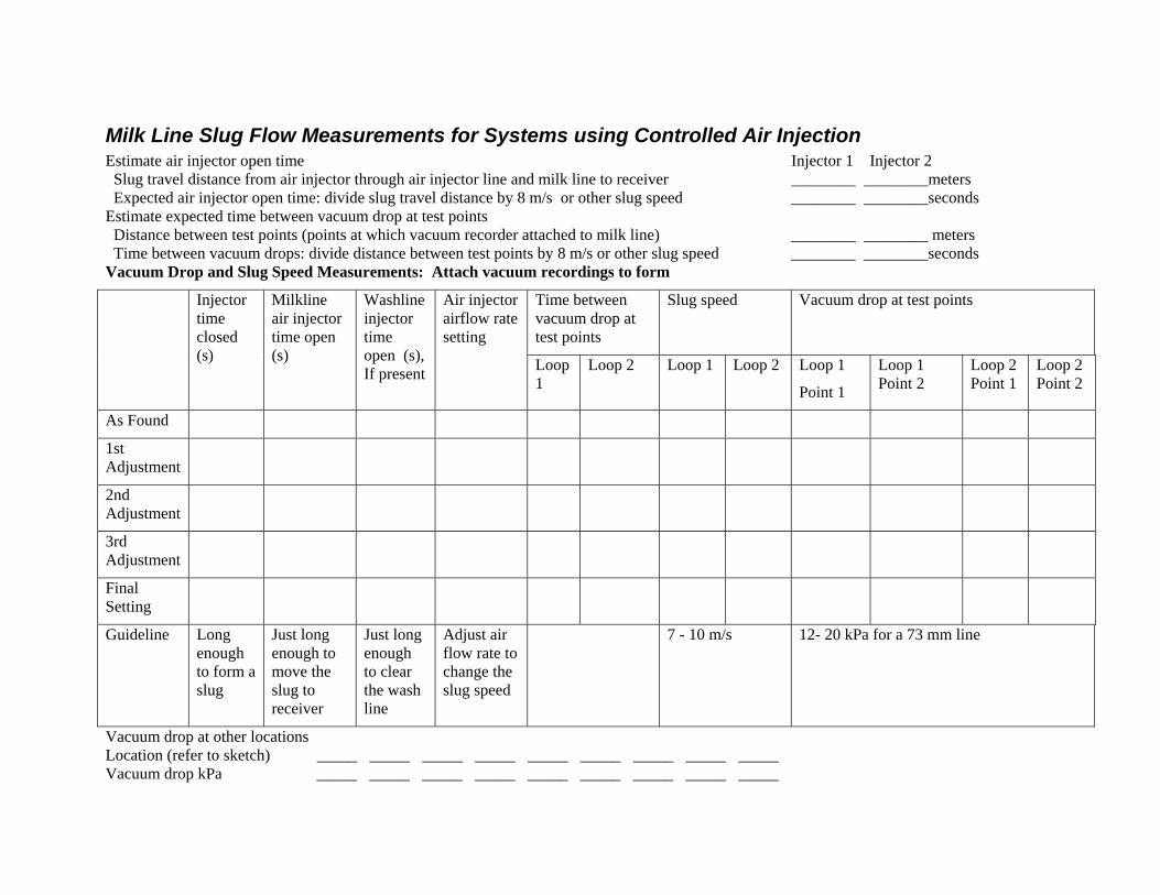
Milk Line Slug Flow Measurements for Systems using Controlled Air Injection Estimate air injector open time Injector 1 Injector 2 Slug travel distance from air injector through air injector line and milk line to receiver ________ ________meters Expected air injector open time: divide slug travel distance by 8 m/s or other slug speed ________ ________seconds Estimate expected time between vacuum drop at test points Distance between test points (points at which vacuum recorder attached to milk line) ________ ________ meters Time between vacuum drops: divide distance between test points by 8 m/s or other slug speed ________ ________seconds Vacuum Drop and Slug Speed Measurements: Attach vacuum recordings to form
Time between vacuum drop at test points
Slug speed Vacuum drop at test points Injector time closed (s)
Milkline air injector time open (s)
Washline injector time open (s), If present
Air injector airflow rate setting
Loop 1
Loop 2 Loop 1 Loop 2 Loop 1
Point 1
Loop 1 Point 2
Loop 2 Point 1
Loop 2 Point 2
As Found
1st Adjustment
2nd Adjustment
3rd Adjustment
Final Setting
Guideline Long enough to form a slug
Just long enough to move the slug to receiver
Just long enough to clear the wash line
Adjust air flow rate to change the slug speed
7 - 10 m/s 12- 20 kPa for a 73 mm line
Vacuum drop at other locations Location (refer to sketch) _____ _____ _____ _____ _____ _____ _____ _____ _____ Vacuum drop kPa _____ _____ _____ _____ _____ _____ _____ _____ _____