review of strengthening techniques using externally bonded fiber reinforced polymer composites
TRANSCRIPT

8/21/2019 Review of Strengthening Techniques Using Externally Bonded Fiber Reinforced Polymer Composites
http://slidepdf.com/reader/full/review-of-strengthening-techniques-using-externally-bonded-fiber-reinforced 1/67
REVIEW OF STRENGTHENING
TECHNIQUES USING EXTERNALLY
BONDED FIBER REINFORCED
POLYMER COMPOSITES
Report 2002-005-C-01
The research described in this report was carried out by
Project Leader Dr. Sujeeva Setunge
Team members Prof. Arun Kumar, Dr. Abe Nezamian and Dr Saman De Silva (RMIT)
Dr. Alan Carse, Mr. John Spathonis and Ms. Louise Chandler (QDMR)
Mr. Dale Gilbert (QDPW)
Mr. Bruce Johnson (Ove Arup)
Prof. Alan Jeary (UWS)
Dr. Lam Pham (CSIRO)
Research Program C:
Delivery and Management o f Bui lt Assets
Project 2002-005-C
Decision Support Tools for Concrete Infrastructure rehabilitation

8/21/2019 Review of Strengthening Techniques Using Externally Bonded Fiber Reinforced Polymer Composites
http://slidepdf.com/reader/full/review-of-strengthening-techniques-using-externally-bonded-fiber-reinforced 2/67
REVIEW OF STRENGTHENING TECHNIQUES USING EXTERNALLY BONDED FRP COMPOSITES
ii
Content Summary
LIST OF TABLES ...........................................................................................V
LIST OF FIGURES.........................................................................................VI
EXECUTIVE SUMMARY..............................................................................VIII
1 GENERAL ................................................................................................ 1
1.1 Introduction ................................................................................................... 1
1.2 Scope and Limitations .................................................................................. 1
1.3 Appl ications and use .................................................................................... 2
1.4 Background Information ............................................................................... 4
1.5 Commercially Available Externally Bonded FRP Systems........................ 5
1.5.1 MBrace composite strengthening systems (MBT Aust ralia) .........................5 1.5.1.1 MBrace FRP fabric (sheet) materials ...........................................................7 1.5.1.2 MBrace S&P CFK laminate strip (plate) .......................................................8
1.5.2 Sika CarboDur composite strengthening systems (CD ROM).......................8
2 MATERIALS ............................................................................................ 9
2.1 Consti tuent Materials .................................................................................... 9
2.1.1 Resins..................................................................................................................9 2.1.1.1 Primer ..............................................................................................................9 2.1.1.2 Putty fillers......................................................................................................9 2.1.1.3 Saturating resin............................................................................................10 2.1.1.4 Adhesives .....................................................................................................10 2.1.1.5 Protective coatings ......................................................................................10
2.1.2 Fibers .................................................................................................................10
2.1.3 MBrace FRP systems .......................................................................................10
2.2 Physical Properties ..................................................................................... 11
2.2.1 Density...............................................................................................................11 2.2.1.1 MBrace fiber .................................................................................................11
2.2.2 Coeff icient of thermal expans ion ...................................................................11
2.3 Mechanical Properties ................................................................................ 11
2.3.1 MBrace FRP st rengthening systems..............................................................13
2.3.2 Sika CarboDur composi te strengthening systems.......................................14
2.4 Time-dependent behavior and durability .................................................. 14 2.4.1 Creep-rupture ...................................................................................................14

8/21/2019 Review of Strengthening Techniques Using Externally Bonded Fiber Reinforced Polymer Composites
http://slidepdf.com/reader/full/review-of-strengthening-techniques-using-externally-bonded-fiber-reinforced 3/67
REVIEW OF STRENGTHENING TECHNIQUES USING EXTERNALLY BONDED FRP COMPOSITES
iii
2.4.2 Fatigue...............................................................................................................14
2.4.3 Durabili ty ...........................................................................................................15
3 INSTALLATION ..................................................................................... 16
3.1 Techniques for FRP Strengthening ........................................................... 16
3.1.1 Basic technique................................................................................................16 3.1.1.1 Substrate.......................................................................................................16 3.1.1.2 Adhesive/Resin ............................................................................................17 3.1.1.3 FRP reinforcement .......................................................................................17
3.1.2 Special techniques ...........................................................................................18 3.1.2.1 Automated wrapping (FIB Bul let in 14, 2001).............................................18 3.1.2.2 Prestressed FRP ..........................................................................................18 3.1.2.3 In-situ fast curing using heating device....................................................20 3.1.2.4 Prefabricated shapes...................................................................................21 3.1.2.5 CFRP inside slits..........................................................................................22 3.1.2.6 FRP impregnation by vacuum ....................................................................23
3.2 Temperature, Humidity, and Moisture Considerations ............................ 23
3.2.1 MBrace FRP strengthening system................................................................24
3.3 Equipment .................................................................................................... 24
3.4 Substrate Repair and Surface Preparation ............................................... 24
3.4.1 MBrace FRP strengthening systems (MBT Australia)..................................25
4 GENERAL DESIGN CONSIDERATIONS.............................................. 27
4.1 Design Philosophy ...................................................................................... 27
4.1.1 Verif ication of the serviceabili ty limit state ...................................................28
4.1.2 Verif ication of the ult imate limit state ............................................................28
4.1.3 Accidental si tuation .........................................................................................28
4.1.4 Special design considerations .......................................................................28
4.1.5 Durabili ty ...........................................................................................................29
4.2 Safety concept and strengthening limits .................................................. 29
4.2.1 Safety concept with respect to the ult imate limit state ................................29
4.2.2 Strengthening limits .........................................................................................30
4.3 Ductility ........................................................................................................ 30
5 FLEXURAL STRENGTHENING ............................................................ 31
5.1 Init ial Situation ............................................................................................. 32
5.2 Design Assumptions................................................................................... 32
5.3 Failure Modes .............................................................................................. 33
5.3.1 Full composite action ......................................................................................33

8/21/2019 Review of Strengthening Techniques Using Externally Bonded Fiber Reinforced Polymer Composites
http://slidepdf.com/reader/full/review-of-strengthening-techniques-using-externally-bonded-fiber-reinforced 4/67
REVIEW OF STRENGTHENING TECHNIQUES USING EXTERNALLY BONDED FRP COMPOSITES
iv
5.3.2 Loss of composite action ................................................................................34 5.3.2.1 Separation of concrete cover .....................................................................34 5.3.2.2 Separation of FRP plate ..............................................................................34 5.3.2.3 Bond failure in interface..............................................................................35
5.4 Summary o f Design Procedure.................................................................. 35
5.5 Special Cases .............................................................................................. 36
5.5.1 Pre-tensioned or post -tensioned concrete elements ...................................36 5.5.1.1 FRP strengthening of prestressed concrete member..............................37 5.5.1.2 Safety considerations ..................................................................................37 5.5.1.3 Modeling issues ...........................................................................................37
5.5.2 Strengthening wi th prest ressed FRP.............................................................38 5.5.2.1 Design ...........................................................................................................38 5.5.2.2 Prestress losses ..........................................................................................38 5.5.2.3 FRP end anchorage .....................................................................................38
6 STRENGTHENING IN SHEAR AND TORSION .................................... 39
6.1 General Design Considerations ................................................................. 39
6.2 Wrapping Schemes ..................................................................................... 40
6.3 Shear Strength............................................................................................. 42
6.4 Strengthening in Tors ion............................................................................ 43
7 AXIAL COMPRESSION, TENSION AND DUCTILITY ENHANCEMENT
45
7.1 Ax ial Compression ...................................................................................... 45
7.2 Tensi le Strengthening ................................................................................. 47
7.3 Ductility ........................................................................................................ 47
8 USE OF FRP BARS AS PRIMARY REINFORCEMENT ....................... 49
8.1 Appl ications of FRP bars ............................................................................ 51
8.2 Design Considerations ............................................................................... 52
9 SUMMARY OF THE STRENGTHENING TECHNIQUES ...................... 53
10 REFERENCES....................................................................................... 54

8/21/2019 Review of Strengthening Techniques Using Externally Bonded Fiber Reinforced Polymer Composites
http://slidepdf.com/reader/full/review-of-strengthening-techniques-using-externally-bonded-fiber-reinforced 5/67
REVIEW OF STRENGTHENING TECHNIQUES USING EXTERNALLY BONDED FRP COMPOSITES
v
List of Tables
Table 2-1: Typical densities of FRP materials, kg/m3 (ACI Committee 440, 2002)... 11
Table 2-2: Typical densities of MBrace FRP composites, kg/m3............................... 11
Table 2-3: Typical coefficients of thermal expansion for FRP materials.* (ACICommittee 440, 2002)....................................................................................... 11
Table 2-4: Typical properties of prefabricated FRP strips and comparison with steel(FIB Bulletin 14, 2001)....................................................................................... 12
Table 2-5: Example showing the effect of volume fraction of fibers on the FRPproperties (FIB Bulletin 14, 2001)...................................................................... 12
Table 2-6: Properties of MBrace FRP fabric strengthening systems ........................ 13
Table 2-7: Properties of MBrace FRP plate strengthening systems ......................... 13
Table 2-8: Properties of Sika CarboDur strengthening systems (CD ROM)............. 14
Table 3-1: Main characteristics and typical aspects of FRP composites, basictechnique (FIB Bulletin 14, 2001) ...................................................................... 17
Table 9-1: Summary of strengthening techniques .................................................... 53

8/21/2019 Review of Strengthening Techniques Using Externally Bonded Fiber Reinforced Polymer Composites
http://slidepdf.com/reader/full/review-of-strengthening-techniques-using-externally-bonded-fiber-reinforced 6/67
REVIEW OF STRENGTHENING TECHNIQUES USING EXTERNALLY BONDED FRP COMPOSITES
vi
List of Figures
Figure 1-1: Uniaxial tension stress-strain diagrams for different unidirectional FRPsand steel. CFRP = carbon FRP, AFRP = aramid FRP, GFRP = glass FRP. ...... 2
Figure 1-2: Typical FRP applications as strengthening materials of RC structures: (a)flexural strengthening of slab; (b) flexural strengthening of beam; (c) shearstrengthening and confinement of column; (d) wrapping of concrete tank; (e)shear strengthening of beam-column joint. ......................................................... 3
Figure 1-3: Stress-strain diagrams (MBT Australia).................................................... 7
Figure 2-1: Stress strain relations corresponding to various fiber volume fractions V fib in Table 2-5 ....................................................................................................... 13
Figure 3-1: (a) Hand lay-up CFRP sheets. (b) Application of prefabricated strips .... 16
Figure 3-2: Automated RC column wrapping. (a) Schematic (b) Photograph of robot-wrapper ............................................................................................................. 18
Figure 3-3: Strengthening with prestressed FRP strips (a) prestressing (b) bonding(c) end anchorage and FRP release upon hardening of the adhesive.............. 19
Figure 3-4: Schematic illustration of active anchorage.............................................. 20
Figure 3-5: Fast curing using heating device: (a) Schematic, (b) Photograph of end
brackets............................................................................................................. 20
Figure 3-6: Example of prefab shapes for strengthening (a) angle (b) application ofangles, (c) shell ................................................................................................. 21
Figure 3-7: CFRP strips glued into slits..................................................................... 22
Figure 3-8: Strengthening with vacuum injection system (Täljsten and Elfgren 2000).......................................................................................................................... 23
Figure 4-1: Strain distribution at Ultimate Limit State in the critical section ofstrengthened flexural members......................................................................... 29
Figure 5-1: Flexural strengthening of RC beams with CFRP strips........................... 31
Figure 5-2: Design stress-strain curves of constitutive materials at Ultimate LimitState. ................................................................................................................. 32
Figure 5-3: Different interfaces for bond failure......................................................... 34
Figure 5-4: Different debonding lines in the concrete ............................................... 34
Figure 5-5: Bond failure modes of a concrete member with EBR (Blaschko et al.1998). ................................................................................................................ 35
Figure 6-1: Schematic illustration of shear failure response ..................................... 40

8/21/2019 Review of Strengthening Techniques Using Externally Bonded Fiber Reinforced Polymer Composites
http://slidepdf.com/reader/full/review-of-strengthening-techniques-using-externally-bonded-fiber-reinforced 7/67
REVIEW OF STRENGTHENING TECHNIQUES USING EXTERNALLY BONDED FRP COMPOSITES
vii
Figure 6-2: Shear strengthening of: (a) beam end; (b) short column ........................ 41
Figure 6-3: Schematic illustration of reinforced concrete element strengthened inshear with FRP: (a) FRP sheets or fabrics bonded to the web; (b) wrapped or U-shaped FRP (the concept shown in D is applicable to both beams and columns)........................................................................................................................... 41
Figure 6-4: CFRP contribution to shear capacity for two different concrete strengthsand fully wrapped (properly anchored) versus unwrapped configurations........ 43
Figure 6-5: (a) Torsional and (b) shear cracking....................................................... 44
Figure 6-6: Forces carried by the FRP reinforcement............................................... 44
Figure 7-1: Comparison of confinement actions of steel and FRP materials ............ 46
Figure 7-2: Triaxial state of stress in FRP jackets..................................................... 47
Figure 7-3: Column failures in Kobe 1995 earthquake (EQE 1995).......................... 48
Figure 8-1: Use of GFRP rebars in construction of Sierrita de la Cruz Creek Bridge,RM1061 Amarillo Texas (Aslan FRP, 2004)...................................................... 51

8/21/2019 Review of Strengthening Techniques Using Externally Bonded Fiber Reinforced Polymer Composites
http://slidepdf.com/reader/full/review-of-strengthening-techniques-using-externally-bonded-fiber-reinforced 8/67
REVIEW OF STRENGTHENING TECHNIQUES USING EXTERNALLY BONDED FRP COMPOSITES
viii
EXECUTIVE SUMMARY
This report reviews the selection, design, and installation of fiber reinforced polymersystems for strengthening of reinforced concrete or pre-stressed concrete bridgesand other structures. The report is prepared based on the knowledge gained fromworldwide experimental research, analytical work, and field applications of FRPsystems used to strengthen concrete structures. Information on material properties,design and installation methods of FRP systems used as external reinforcement are
presented. This information can be used to select an FRP system for increasing thestrength and stiffness of reinforced concrete beams or the ductility of columns, andother applications.
Based on the available research, the design considerations and concepts arecovered in this report. In the next stage of the project, these will be further developedas design tools. It is important to note, however, that the design concepts proposedin literature have not in many cases been thoroughly developed and proven.Therefore, a considerable amount of research work will be required prior todevelopment of the design concepts into practical design tools, which is a major goalof the current research project.
The durability and long-term performance of FRP materials has been the subject ofmuch research, which still are on going. Long-term field data are not currentlyavailable, and it is still difficult to accurately predict the life of FRP strengtheningsystems. The report briefly addresses environmental degradation and long-termdurability issues as well.
A general overview of using FRP bars as primary reinforcement of concretestructures is presented in Chapter 8.
In Chapter 9, a summary of strengthening techniques identified as part of this initialstage of the research project and the issues which require careful consideration priorto practical implementation of these identified techniques are presented.

8/21/2019 Review of Strengthening Techniques Using Externally Bonded Fiber Reinforced Polymer Composites
http://slidepdf.com/reader/full/review-of-strengthening-techniques-using-externally-bonded-fiber-reinforced 9/67
REVIEW OF STRENGTHENING TECHNIQUES USING EXTERNALLY BONDED FRP COMPOSITES
1
1 General
1.1 Introduction
Rehabilitation of deteriorated civil engineering infrastructure such as bridge decks,buildings, beams, girders, parking structures, marine structures, roads etc has beena major issue in the last decades. The deterioration of these structures might be dueto ageing, poor maintenance, corrosion due to poor environmental conditions, poorinitial design or construction and accidental situations like earthquakes. The need toupgrade the deteriorated civil engineering infrastructure greatly enhances with theever increasing demands. For example, the increased traffic conditions normally donot match with the initial design load actions. Therefore rehabilitating existing civilengineering infrastructure has been identified as an important issue to be addressed.
Transportation agencies are faced with a continuous challenge to keep bridges in a
good operation condition despite limited resources. Bridge structures aredeteriorating at a fast rate, and cost for repair and replacement of deficient bridgesare continuously rising. Even when resources are available, extended time is oftenrequired for performing needed remedies, causing disruption of traffic andinconvenience to the traveling public. The strengthening or retrofitting of existingconcrete structures to resist higher design loads, correct deterioration-relateddamage, or increased ductility has traditionally been accomplished usingconventional materials and construction techniques. Externally bonded steel plates,steel or concrete jackets and external post tensioning are just some of the manytraditional techniques available. In the context of the strengthening problem,advanced composites have the potential to prove another promising solution.
New technology options in bridge rehabilitation are being developed from polymers,metals, ceramics and composites of these materials, and some of these highperformance materials are already being utilized in construction. Compositescomprise of several different basic components that together provide physicalcharacteristics superior to what each can provide separately. While the concept ofcomposites has been in existence for several millennia, the incorporation of fiberreinforced polymer (FRP) is less than a century old. These composites combine thestrength of the fibers with the stability of the polymer resins. They are defined aspolymer matrix, either thermo-set or thermoplastic, that are reinforced with fibers orother reinforcing material with a sufficient aspect ratio (length to thickness) to providea desirable reinforcing function in one or more directions. These composite materials
are different form traditional construction materials such as steel, aluminum, andconcrete because they are anisotropic; i.e., the properties differ depending on thedirection of the fibers. Due to the resulting benefits, FRP composite applications haverevolutionized entire industries including aerospace, marine, electrical, andtransportation (Nystrom at el. 2003).
These composite materials gain their superior characteristics from the componentmaterials used. Their strength comes largely from the fibers, which are usually glass,carbon, or aramid fiber.
1.2 Scope and Limitations
This report reviews the selection, design, and installation of FRP systems forexternally strengthening of reinforced concrete bridges. FRP systems can be used to

8/21/2019 Review of Strengthening Techniques Using Externally Bonded Fiber Reinforced Polymer Composites
http://slidepdf.com/reader/full/review-of-strengthening-techniques-using-externally-bonded-fiber-reinforced 10/67
REVIEW OF STRENGTHENING TECHNIQUES USING EXTERNALLY BONDED FRP COMPOSITES
2
rehabilitate or restore the strength of a deteriorated structural member, or retrofit orstrengthen a sound structural member to resist increased loads due to changes inuse of the structure, or address design or construction errors. It should bedetermined if a FRP system is a suitable strengthening technique before selectingthe type of FRP system. To assess suitability of a FRP system for a particularapplication, the condition assessment of the existing structure should be performedand the best treatment option would be then determined based on the assessment
(ACI, 440, 2002).
Composite materials for strengthening civil engineering structures have severaldisadvantages too. They in general behave in a linear elastic manner and fails atlarge strains (no yielding point and reduced ductility). This is contrary to theconventional steel which behaves in an elasto-plastic manner. Typical stress-straincurves for unidirectional composites subjected to monotonic loading are shown inFigure 1-1. A similar curve for steel is also shown in the same figure for comparison.
Figure 1-1: Uniaxial tension stress-strain diagrams for different unidirectional FRPs and steel. CFRP =
carbon FRP, AFRP = aramid FRP, GFRP = glass FRP (FIB Bulletin 14, 2001).
Moreover the cost of composite materials on a weight basis is several times higherthan that for steel. However when compared in terms of strength, composites arebetter. Some FRP materials, e.g. carbon and aramid, have incompatible thermalexpansion coefficients with concrete. As a result premature degradation and collapsemay occur when subjected to high temperatures. Selection of FRP composites forstrengthening purpose has to be based not only on mechanical performance aspects,but also on constructability and long-term durability. Therefore it is necessary toconsider all the design issues without treating FRP as a blind replacement of steel.
The durability and long term performance of FRP materials are covered only briefly inthis report since reported literature does not fully cover the topic.
1.3 Applications and use
There are a number of applications of FRP composites as the strengthening materialof reinforced concrete elements. FRP composite strips can be bonded to the externaltension zones of beams and slabs thus increasing the flexural strength of theelement (Figure 1-2 a, b).

8/21/2019 Review of Strengthening Techniques Using Externally Bonded Fiber Reinforced Polymer Composites
http://slidepdf.com/reader/full/review-of-strengthening-techniques-using-externally-bonded-fiber-reinforced 11/67
REVIEW OF STRENGTHENING TECHNIQUES USING EXTERNALLY BONDED FRP COMPOSITES
3
Figure 1-2: Typical FRP applications as strengthening materials of RC structures: (a) flexuralstrengthening of slab; (b) flexural strengthening of beam; (c) shear strengthening and confinement ofcolumn; (d) wrapping of concrete tank; (e) shear strengthening of beam-column joint. (FIB 14, 2001)
FRP fabrics or sheets can be wrapped around reinforced concrete columns thus
increasing the confinement and the axial strength. Furthermore it increases theflexural, shear and torsion strengths and improves the ductility (Figure 1-2 c, d).

8/21/2019 Review of Strengthening Techniques Using Externally Bonded Fiber Reinforced Polymer Composites
http://slidepdf.com/reader/full/review-of-strengthening-techniques-using-externally-bonded-fiber-reinforced 12/67
REVIEW OF STRENGTHENING TECHNIQUES USING EXTERNALLY BONDED FRP COMPOSITES
4
Shear strengthening in beam-column joints is another application of FRP compositeswhich was developed recently (Figure 1-2 e).
Before using FRP system for strengthening a particular structure, an initial conditionassessment of the existing structure needs to be performed. The assessment shouldbe the result of a thorough field inspection and review of existing design. In theseinspections, it is possible to study the capacity of the existing structure, identify thedeficiencies and causes and determine the condition of concrete substrate. As shownin the ACI Committee 440 (2002), a field inspection should include the following:
• Existing dimensions of the structural members;
• Location, size, and cause of cracks and spalls;
• Location and extent of corrosion of reinforcing steel;
• Quantity and location of existing reinforcing steel;
• In-place compressive strength of concrete; and
• Soundness of concrete, especially the concrete cover, in all areas where theFRP system is to be bonded to the concrete.
1.4 Background Information
Steel plate bonding and steel or concrete column jacketing are the traditionalmethods of external reinforcing. Steel plates bonded to the tension zones of concretemembers have shown to be increasing the flexural capacity of the members (Fleming
and King, 1967). This traditional method has been used over the world to strengthenbridges and buildings. However, the corrosion of steel plates, deterioration of thebond between steel and concrete, installation difficulties such as necessity of heavyequipment in installing have been identified as major drawbacks of this technique. Asa result researchers investigated FRP strengthening as an alternative to this method.
The United Stats has shown an interest of fiber based reinforcement in concretestructures since 1930s. However, actual development and research into the use ofthese materials for retrofitting concrete structures started in the 1980’s through theinitiatives of the National Science Foundation (NSF) and the Federal Highway Administration (FHWA). Using FRP materials for retrofitting concrete structures wasreported as early as 1978 in Germany (Wolf and Miessler, 1989). Same kinds of
investigations to retrofit concrete structures were reported in Europe and Japan in the1980s. Externally bonded FRP systems have been used to strengthen concretestructures around the world from mid 1980s. Research in Switzerland leads to thefirst applications of externally bonded FRP systems to reinforced concrete bridges forflexural strengthening (Meier 1987; Rostasy 1987). FRP systems were used as analternative to steel plate bonding in Europe. Using FRP systems to increase theconfinement was first applied in Japan in the 1980s (Fardis and Khalili 1981;Katsumata et al. 1987). Utilizing FRP systems around the world has been increasingfrom a few projects ten years ago to several thousands today (Bakis et al. 2002). InJapan FRP usage has been increased after the 1995 Hyogoken Nanbu earthquake(Nanni 1995).
FRP Externally bonded FRP systems have also been applied to strengthen masonry,timber, steel and cast iron. They have been used in structural elements such as

8/21/2019 Review of Strengthening Techniques Using Externally Bonded Fiber Reinforced Polymer Composites
http://slidepdf.com/reader/full/review-of-strengthening-techniques-using-externally-bonded-fiber-reinforced 13/67
REVIEW OF STRENGTHENING TECHNIQUES USING EXTERNALLY BONDED FRP COMPOSITES
5
beams, slabs, columns, walls, joints/connections, chimneys and smokestacks, vaults,domes, tunnels, silos, pipes, and trusses.
The development of the design rules and guidelines for the field application ofexternally bonded FRP systems is ongoing in Europe, Japan, Canada and UnitedStates. Within last 10 year Japan Society of Civil Engineers (JSCE, 2001) and theJapan Concrete Institute (JCI, 1997 and 1998) and the Railway Technical ResearchInstitute (RTRI, 1996) made several publications related to FRP systems in concretestructures (Japan Concrete Institute 1997; Neale (2000), Dolan et al. (1999); Shehetaet al. 1999; Saadatmanesh and Ehsani (1998), Benmokrane and Rahman 1998).
Previous research and field applications for FRP rehabilitation and strengthening aredescribed in ACI Committee 440 (2002). In Europe Task Groip 9.3 of the InternationalFederation for Structural Concrete (FIB) published a bulletin on design guidelines forexternally bonded FRP reinforcement for reinforced concrete structures (FIB Bulletin14, 2001). Section 16, “Fiber Reinforced Concrete”, of the Canadian Highway BridgeDesign Code was completed in 2000 (CSA 2000) and the Canadian Standards
Association (CSA) recently approved the code “Design and Construction of BuildingComponents with Fiber Reinforced Polymers (CSA 2002).
1.5 Commercially Available Externally Bonded FRP Systems
Composite materials for strengthening structures are available in the form ofunidirectional thin strips made by pultrusion or sheets or fabrics made of fibres one orat least two different directions.
Suppliers of FRP systems in Australia are Master Builders Technologies (MBT) andSika Services Corporate Construction. MBT supplies two MBrace CompositeStrengthening Systems. The first one is the MBrace FRP fabric (sheet) materialsincluding carbon, aramid and glass fibres while the other system is MBrace S&P CFKlaminate strip (plate) (carbon fibre laminate materials). Sika CarboDur compositestrengthening systems supply flexural strengthening products (plates), shearstrengthening products (L-shaped strips) and shear strengthening and confinementproducts (flexible sheets). The Sika products include carbon, aramid and glass fibres.These commercially available composite strengthening systems are described inbrief in the following sections of the report.
1.5.1 MBrace composite strengthening systems (MBT Australia)
The MBrace Composite Strengthening System comprises of a family of lightweight
FRP materials. They are externally bonded to the surface of structures to enhancethe strength. These systems provide very high tensile strength and are used forflexural and shear reinforcement and axial compression confinement of concrete,masonry and timber elements.
The MBT-MBrace sheets (either uni-directional or bi-directional) can be applied asdry and wet lay ups and also as preimpregnated Prepegs. Types of fibres used inMBrace FRP systems are carbon, aramid and glass (uncoated E-glass whichcorrodes in alkaline environment and Alkali resistant glass-AR glass). Stress-straindiagram for these fibres is shown in

8/21/2019 Review of Strengthening Techniques Using Externally Bonded Fiber Reinforced Polymer Composites
http://slidepdf.com/reader/full/review-of-strengthening-techniques-using-externally-bonded-fiber-reinforced 14/67
REVIEW OF STRENGTHENING TECHNIQUES USING EXTERNALLY BONDED FRP COMPOSITES
6
Figure 1-3.

8/21/2019 Review of Strengthening Techniques Using Externally Bonded Fiber Reinforced Polymer Composites
http://slidepdf.com/reader/full/review-of-strengthening-techniques-using-externally-bonded-fiber-reinforced 15/67
REVIEW OF STRENGTHENING TECHNIQUES USING EXTERNALLY BONDED FRP COMPOSITES
7
Figure 1-3: Stress-strain diagrams (MBT Australia)
s
The basic fibers in MBrace FRP systems are embedded in a polymer matrix wherethe arrangement of fibers can be either unidirectional or bidirectional.
1.5.1.1 MBrace FRP fabric (sheet) materials
MBrace FRP fabric sheets can be stretched or woven and uni-directional or bi-directional.
1.5.1.1.1 Stretched sheets
Uni-directional arrangement:
In the stretched sheets fibres are bonded to a tight mesh and parallel fibres arestretched. Therefore these sheets have high elastic modulus. These are moresuitable for increasing the structural capacity of an element.
1.5.1.1.2 Woven sheets
Bi-directional arrangement:
Woven sheets are produced by weaving and the arrangement of fibres is bidirectional. These sheets are less suitable for increasing the structural capacity of an
element as the fibres are slightly wavy. These bi directional sheets are more suitablefor increasing the ductility of a structure component.
1.5.1.1.3 Uni-directional and bi-directional MBT-MBrace FRP sheets
Either cold curing epoxy resin matrix or the thermally curing epoxy resin matrix isused to ensure the load transfer from the sheets to the substrate.
1.5.1.1.4 Cold curing epoxy resin matrix:
Uni directional and bi directional sheets are applied as a dry lay up if the weight isless than 400 gm/m2. In this case the cold curing epoxy resin is rolled onto the
structural element and dry sheet is applied into the matrix.

8/21/2019 Review of Strengthening Techniques Using Externally Bonded Fiber Reinforced Polymer Composites
http://slidepdf.com/reader/full/review-of-strengthening-techniques-using-externally-bonded-fiber-reinforced 16/67
REVIEW OF STRENGTHENING TECHNIQUES USING EXTERNALLY BONDED FRP COMPOSITES
8
Stretched and woven sheets are applied as a wet lay up if the weight is less than400-800 gm/m2. Contrary to the dry lay up situation, in this case the sheets areimpregnated with the cold curing epoxy matrix and then applied wet to the structuralelement.
1.5.1.1.5 Thermally curing epoxy resin matrix:
The uni-directional and bi-directional sheets are impregnated with the thermallycuring epoxy adhesive at the manufacturer’s facility. Thermal curing is done byapplying additional heat to the epoxy resin on the element. This method is called thePrepeg systems.
1.5.1.2 MBrace S&P CFK laminate str ip (plate)
Prefabricated FRP is supplied to the job site as a composite (laminate). The supplierdoes the impregnation with the epoxy resin matrix and thermal curing undercontrolled factory conditions. A commonly used laminate used for structural
strengthening is the MBT-MBrace Laminate CFK.
1.5.2 Sika CarboDur composite strengthening systems (CD ROM)
Sika CarboDur composite strengthening systems include flexural strengtheningproducts (plates), shear strengthening products (L-shaped strips) and shearstrengthening or confinement products (flexible sheets).

8/21/2019 Review of Strengthening Techniques Using Externally Bonded Fiber Reinforced Polymer Composites
http://slidepdf.com/reader/full/review-of-strengthening-techniques-using-externally-bonded-fiber-reinforced 17/67
REVIEW OF STRENGTHENING TECHNIQUES USING EXTERNALLY BONDED FRP COMPOSITES
9
2 Materials
In this chapter, the physical and mechanical properties of FRP composites arepresented. The characteristics of FRP composites depend on many factors such astype of fiber, its orientation and volume, type of resin used and quality control usedduring the manufacturing process. It is possible to obtain the characteristics ofcommercially available FRP composites from the manufacturer. However, somegeneric material characteristics are described in this chapter.
2.1 Constituent Materials
There are several constituent materials in commercially available FRP repair systemssuch as resins, primers, putties, saturants, adhesives, and fibers.
2.1.1 Resins
A large variety of resins are used with FRP systems. The most commonly usedresins can normally be used in different environmental conditions. However as shownby the ACI Committee 440 (2002), FRP system manufacturers use resins that havethe following characteristics:
• Compatibility with and adhesion to the concrete substrate;
• Compatibility with and adhesion to the FRP composite system;
• Resistance to environmental effects, including but not limited to, moisture, saltwater, temperature extremes, and chemicals normally associated with exposedconcrete;
• Filling ability;
• Workability;
• Pot life consistent with the application;
• Compatibility with and adhesion to the reinforcing fiber; and
• Development of appropriate mechanical properties for the FRP composite.
2.1.1.1 Primer
The primer is used to penetrate the surface of the concrete, providing an improvedadhesive bond for the saturating resin or adhesive.
In MBrace FRP systems, MBrace primer is the recommended primer to ensuremaximum bond for MBrace Laminate Adhesive and MBrace Saturant. It is a two-partepoxy product with low viscosity and 100% solids content.
2.1.1.2 Putty fillers
The putty is used to fill small surface voids in the substrate, such as bug holes, andto provide a smooth surface to which the FRP system can bond. Filled surface voids
also prevent bubbles from forming during curing of the saturating resin.

8/21/2019 Review of Strengthening Techniques Using Externally Bonded Fiber Reinforced Polymer Composites
http://slidepdf.com/reader/full/review-of-strengthening-techniques-using-externally-bonded-fiber-reinforced 18/67
REVIEW OF STRENGTHENING TECHNIQUES USING EXTERNALLY BONDED FRP COMPOSITES
10
2.1.1.3 Saturating resin
The saturating resin is used to impregnate the reinforcing fibers, fix them in place,and provide a shear load path to effectively transfer load between fibers. Thesaturating resin also serves as the adhesive for wet lay-up systems, providing ashear load path between the previously primed concrete substrate and the FRPsystem.
MBrace Saturant is the recommended resin adhesive for use with MBrace Fibersheet (wet or dry) lay-up systems. It is a two-part epoxy product with 100% solidscontent.
2.1.1.4 Adhesives
Adhesives are used to bond precured FRP laminate systems to the concretesubstrate. The adhesive provides a shear load path between the concrete substrateand the FRP reinforcing laminate. Adhesives are also used to bond together multiple
layers of precured FRP laminates.
MBrace Laminate Adhesive is the adhesive for the MBrace S&P CFK LaminateSystem and a filling compound for irregular surfaces.
2.1.1.5 Protective coatings
The protective coating is used to protect the bonded FRP reinforcement frompotentially damaging environmental effects. Coatings are typically applied to theexterior surface of the cured FRP system after the adhesive or saturating resin hascured.
2.1.2 Fibers
Continuous glass, aramid, and carbon fibers are common reinforcements used withFRP systems. The fibers give the FRP system its strength and stiffness.
2.1.3 MBrace FRP systems
These systems consist of the following components.
• Primer – improves the bonding of the composite to the substrate
• Concresive 1444/1446 to even out any imperfections in the base (pitting,
macro roughness etc)• MBrace Saturant for wetting out the fiber sheet materials in a “Dry or Wet
Lay-Up”, to form the composite in-situ
• MBrace Resicem Saturant for wetting out the fiber sheet materials in a “Dry orWet Lay-Up”, to form the composite in-situ, which is vapor permeable
• MBrace Laminate Adhesive for adhesion of carbon laminates (and a levelingcompound)
• MBrace Fibre (Carbon, Aramid or Glass) fiber sheet reinforcement for “Dry orWet Lay-Up”
• MBrace S&P CFK Laminate prefabricated composite carbon fiber laminate
• Barracryl D acrylic topcoat, resistant to UV rays

8/21/2019 Review of Strengthening Techniques Using Externally Bonded Fiber Reinforced Polymer Composites
http://slidepdf.com/reader/full/review-of-strengthening-techniques-using-externally-bonded-fiber-reinforced 19/67
REVIEW OF STRENGTHENING TECHNIQUES USING EXTERNALLY BONDED FRP COMPOSITES
11
2.2 Physical Properties
2.2.1 Density
The densities of FRP composites with Glass, Carbon and Aramid are shown in Table
2-1 (ACI Committee 440, 2002). The density of steel is also presented there ascomparison. It is clearly seen from the table that density of FRP composites are fourto six times lower than that of steel. The reduced density is a desirable property as itreduces transportation and handling cost and additional dead load on structure.
Table 2-1: Typical densities of FRP materials, kg/m3 (ACI Committee 440, 2002)
Steel GFRP CFRP AFRP
7900 1200 - 2100 1500 - 1600 1200 - 1500
2.2.1.1 MBrace fiber
The commercially available MBrace FRP strengthening system in Australia also usescarbon, aramid and glass fibers. The density of each FRP composite is shown inTable 2-2.
Table 2-2: Typical densities of MBrace FRP composites, kg/m3
MBrace fiber Density (kg/m3)
Carbon – high modulus 2100
Carbon – high tensile 1700
Aramid 1450
E-glass or AR-glass 2600 (2680)
2.2.2 Coefficient of thermal expansion
Table 2-3 (ACI Committee 440, 2002) shows the coefficients of thermal expansion fortypical unidirectional FRP materials. It is clearly seen that it changes in thelongitudinal and transverse directions and also depending on the type of fiber,volume of fiber and resin. The coefficient of thermal expansion of concrete rangesfrom 7×10⁻⁶ to 11×10-6/C and is usually assumed to be isotropic. Steel has anisotropic coefficient of thermal expansion of 11.7×10⁶/C.
Table 2-3: Typical coefficients of thermal expansion for FRP materials.* (ACI Committee 440, 2002)
Coefficient of thermal expansion, ×10-6
/CDirection
GFRP CFRP AFRP
Longitudinal 6 to 10 -1 to 0 -6 to –2
Transverse 19 to 23 22 to 50 60 to 80
2.3 Mechanical Properties
FRP materials compose of a number of continuous, directionalized, nonmetallicfibers, bundled in a resin matrix. Normally, the volume fraction of fibers in FRP strips

8/21/2019 Review of Strengthening Techniques Using Externally Bonded Fiber Reinforced Polymer Composites
http://slidepdf.com/reader/full/review-of-strengthening-techniques-using-externally-bonded-fiber-reinforced 20/67
REVIEW OF STRENGTHENING TECHNIQUES USING EXTERNALLY BONDED FRP COMPOSITES
12
is about 50-70% and that in FRO sheets is about 25-35%. Fibers are the principalstress bearing constituents, while the resin transfers stresses among fibers andprotects them. If these volume fractions and properties of constituent materials (fibersand matrix) are known for a particular FRP composite then mechanical propertiescan be obtained as shown in FIB Bulletin 14 (2001).
mm fib fib f V E V E E += (2- 1)
mm fib fib f V f V f f +≈ (2- 2)
where, Ef = Young’s modulus of FRP in fiber direction, Efib = Young’s modulus offibers, Em= Young’s modulus of matrix, Vfib = volume fraction of fibers, Vm = volumefraction of matrix, f f = tensile strength of FRP in fiber direction, f fib = tensile strength offibers and, f m = tensile strength of matrix. Note that in the above equations Vfib + Vm = 1. Also, typical values for the volume fraction of fibers in prefabricated strips are inthe order of 0.50 – 0.65.
FIB Bulletin 14 (2001) shows the properties of commercially available FRPprefabricated strips (Table 2-4). For these strips normally manufacturer provides thematerial properties.
Table 2-4: Typical properties of prefabricated FRP strips and comparison with steel (FIB Bulletin 14,2001)
Material Elastic modulus(GPa) - Ef
Tensile strength(MPa) - f f
Ultimate tensile strain
(%) - εfu
Prefabricated stripsLow modulus CFRPHigh modulus CFRP
170300
28001300
1.60.5
Mild steel 200 400 25** Yield strain = 0.2 %
In in-situ resin impregnated systems, the final FRP thickness and thus the fibervolume is uncertain. Therefore the composite material properties based on theproperties on fibers and matrix may not be appropriate. Sometimes manufacturersprovide the material properties for the bare fibers. There is a strong relationshipbetween the fiber volume fraction and the FRP properties to be used in the propertycalculation of FRP composite. This is shown in Table 2-5 and Figure 2-1.
Table 2-5: Example showing the effect of volume fraction of fibers on the FRP properties (FIB Bulletin14, 2001)
Properties for consti tuent materials of FRP composite:Fiber:Young’s modulus: 220 GPa Tensile strength: 4000 MPaMatrix:Young’s modulus: 3 GPa Tensile strength: 80 MPa
Cross sectional area FRP properties Failure load
Afib (mm
2)
Am (mm
2)
A*f (mm
2)
Vfib (%)
Ef (MPa)Eq. (2-1)
f f (MPa)Eq. (2-1)
Ultimatestrain (%)
(kN) (%)
70 0 70 100 220000 4000 1.818 280.0 100.0
70 30 100 70 154900 2824 1.823 283.4 100.9
70 70 140 50 111500 2040 1.830 285.6 102.0
* In case of a strip with a width of 100 mm dividing this value by 100 mm gives the thicknessof the strip.
8/21/2019 Review of Strengthening Techniques Using Externally Bonded Fiber Reinforced Polymer Composites
http://slidepdf.com/reader/full/review-of-strengthening-techniques-using-externally-bonded-fiber-reinforced 21/67
REVIEW OF STRENGTHENING TECHNIQUES USING EXTERNALLY BONDED FRP COMPOSITES
13
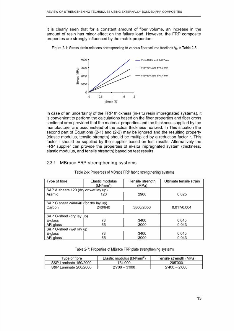
It is clearly seen that for a constant amount of fiber volume, an increase in theamount of resin has minor effect on the failure load. However, the FRP compositeproperties are strongly influenced by the matrix proportion.
Figure 2-1: Stress strain relations corresponding to various fiber volume fractions Vfib in Table 2-5
0
1000
2000
3000
4000
0 0.5 1 1.5 2
Strain (%)
S t r e s s ( M P a )
Vfib=100% and tf=0.7 mm
Vfib=70% and tf=1.0 mm
Vfib=50% and tf=1.4 mm
In case of an uncertainty of the FRP thickness (in-situ resin impregnated systems), itis convenient to perform the calculations based on the fiber properties and fiber crosssectional area provided that the material properties and the thickness supplied by themanufacturer are used instead of the actual thickness realized. In This situation thesecond part of Equations (2-1) and (2-2) may be ignored and the resulting property(elastic modulus, tensile strength) should be multiplied by a reduction factor r. Thisfactor r should be supplied by the supplier based on test results. Alternatively theFRP supplier can provide the properties of in-situ impregnated system (thickness,elastic modulus, and tensile strength) based on test results.
2.3.1 MBrace FRP strengthening systems
Table 2-6: Properties of MBrace FRP fabric strengthening systems
Type of fibre Elastic modulus(kN/mm
2)
Tensile strength(MPa)
Ultimate tensile strain
S&P A sheets 120 (dry or wet lay up) Aramid 120 2900 0.025
S&P C sheet 240/640 (for dry lay up)Carbon 240/640 3800/2650 0.017/0.004
S&P G-sheet (dry lay up)
E-glass 73 3400 0.045 AR-glass 65 3000 0.043
S&P G-sheet (wet lay up)E-glass 73 3400 0.045 AR-glass 65 3000 0.043
Table 2-7: Properties of MBrace FRP plate strengthening systems
Type of fibre Elastic modulus (kN/mm2) Tensile strength (MPa)
S&P Laminate 150/2000 164’000 205’000
S&P Laminate 200/2000 2’700 – 3’000 2’400 – 2’600
8/21/2019 Review of Strengthening Techniques Using Externally Bonded Fiber Reinforced Polymer Composites
http://slidepdf.com/reader/full/review-of-strengthening-techniques-using-externally-bonded-fiber-reinforced 22/67
REVIEW OF STRENGTHENING TECHNIQUES USING EXTERNALLY BONDED FRP COMPOSITES
14
2.3.2 Sika CarboDur composite strengthening systems
The mechanical properties of the Sika CarboDur strengthening systems are asshown in Table 2-8.
Table 2-8: Properties of Sika CarboDur strengthening systems (CD ROM)Type of fibre Elastic modulus (kN/mm
2) Ultimate tensile strain
PlatesCarboDur S-series 165 0.0170CarboDur M-series 210 0.0135CarboDur H-series 300 0.0045
L-shaped stripsCarboshear 120 0.019
Flexible sheetsSikaWrap Hex 103-C 231 0.015
SikaWrap Hex 230-C 231 0.017SikaWrap Hex 430-G 70 0.031
2.4 Time-dependent behavior and durabili ty
2.4.1 Creep-rupture
When FRP composites are subjected to a constant load over a time they failsuddenly. This failure is known as the creep rupture and this time period is known asthe endurance time. The endurance time decreases when the ratio of sustainedtensile stress to the short-term strength of the FRP laminates increases. Furthermore
it decreases with adverse environmental conditions such as high temperature, highalkalinity, freezing-thawing cycles and wet-dry cycles
As stated in ACI Committee 440 (2002) the relationship between creep rupturestrength and the logarithm of time for FRP bars is linear. The ratios of stress level atcreep-rupture after 500,000 hours to the initial ultimate strength of the GFRP, AFRP,and CFRP bars were extrapolated to be 0.3, 0.47, and 0.91, respectively (Yamaguchiet al. 1997). Similar values have been determined elsewhere (Malvar 1998). Thevulnerability of carbon, aramid and glass fibers to creep rupture is increasingrespectively.
2.4.2 Fatigue
Fatigue behavior and life prediction of stand alone FRP materials have been studiedin the last 30 years (American National Research Council 1991). In these studiesaerospace materials were the primary subject of investigation. Based on the testresults some general observations on the fatigue behavior have been made. Testconditions that raise the temperature and moisture content of FRP materialsgenerally degrade the ambient environment fatigue behavior.
Of all FRP composite type, CFRP is least susceptible to fatigue failure having asurvival limit of 60 to 70% (one million cycles) of the initial static ultimate strength ofCFRP. In a stress versus logarithm of the number of cycles at failure graph, the
downward slope of CFRP is about 5% of the initial static ultimate strength per decadeof logarithmic life. Fatigue strength of CFRP is not normally affected by moisture and

8/21/2019 Review of Strengthening Techniques Using Externally Bonded Fiber Reinforced Polymer Composites
http://slidepdf.com/reader/full/review-of-strengthening-techniques-using-externally-bonded-fiber-reinforced 23/67
REVIEW OF STRENGTHENING TECHNIQUES USING EXTERNALLY BONDED FRP COMPOSITES
15
temperature exposures of concrete structures unless the resin or fiber/resin interfaceis substantially deteriorated by the environment.
Individual glass fibers showed a delayed rupture caused by stress corrosion underambient environment laboratory conditions (Mandell 1982). A cyclic tensile fatigueeffect of approximately 10% loss in the initial static strength per decade of logarithmiclifetime is observed for GFRP composites (Mandell 1982). Generally, no clearfatigue limit can be defined. Environmental factors such as moisture, alkaline, andacidic solutions can play an important role in the fatigue behavior of glass fibers.
Aramid fibers exhibit a good fatigue behavior and the tension-tension fatiguebehavior of an impregnated aramid fiber strand is excellent. Strength degradation perdecade of logarithmic lifetime is approximately 5 to 6% (Roylance and Roylance1981). Commercial AFRP tendons for concrete have a survival limit of 54 to 73% ofthe ultimate tensile strength in two million years (Odagiri et al. 1997).
2.4.3 Durability
The tensile strengths provided by the manufacturers of FRP systems are based ontests conducted in a laboratory environment which does not simulate the realenvironment conditions. However, the mechanical properties of FRP systems reducewith many factors such as the adverse environmental exposure (high temperature,humidity and chemicals), the duration of exposure, resin and fiber type and resincuring method.

8/21/2019 Review of Strengthening Techniques Using Externally Bonded Fiber Reinforced Polymer Composites
http://slidepdf.com/reader/full/review-of-strengthening-techniques-using-externally-bonded-fiber-reinforced 24/67
REVIEW OF STRENGTHENING TECHNIQUES USING EXTERNALLY BONDED FRP COMPOSITES
16
3 INSTALLATION
FRP system installation procedure is normally developed by the systemmanufacturer. It differs between systems and even within a system depending on thecondition of the structure. This chapter gives general guidelines for FRP systeminstallation based on international guidelines (FIB Bulletin 14, 2001 and ACICommittee 440, 2002) as well as procedures developed by Australian manufacturers.
3.1 Techniques for FRP Strengthening
The strengthening techniques concern the application of FRP as structuralreinforcement bonded to an existing concrete substrate structure. The technique canbe used under different conditions and at different locations of the structural membertaking into account all specifications and requirements.
3.1.1 Basic technique
The most widely used FRP strengthening technique is the manual application of wetlay-up (hand lay-up) or prefabricated systems using cold cured adhesive bonding.The main and the important feature of this technique is that the fibers of externallybonded FRP composites are in parallel as practicable with the direction of principaltensile stresses. Typical applications of the hand lay-up and prefabricated systemsare illustrated in Figure 3-1. The basic technique of FRP strengthening describedhere refers to the manual application of FRP reinforcement to an existing member. Atwo-part cold cured bonding agent (normally epoxy-based) is used to achievebonding.
Figure 3-1: (a) Hand lay-up CFRP sheets. (b) Application of prefabricated strips (FIB Bulletin 14, 2001).
The basic technique involves three acting elements, defined as follows.
3.1.1.1 Substrate
FRP composite is bonded to an existing structure to enhance its strength. Thematerial type of that structure is the substrate. The behavior of the thus strengthenedstructure heavily depends on a good concrete substrate and the preparation of the
concrete surface. As shown by FIB Bulletin 14 (2001) the initial conditions of theconcrete surface in terms of strength, carbonation, unevenness, imperfections,

8/21/2019 Review of Strengthening Techniques Using Externally Bonded Fiber Reinforced Polymer Composites
http://slidepdf.com/reader/full/review-of-strengthening-techniques-using-externally-bonded-fiber-reinforced 25/67
REVIEW OF STRENGTHENING TECHNIQUES USING EXTERNALLY BONDED FRP COMPOSITES
17
cracks, type and possible corrosion of internal steel reinforcement, humidity, level ofchloride and sulphate ions, etc. should be known.
3.1.1.2 Adhesive/Resin
A suitable adhesive/resin should be selected for a particular FRP strengtheningsystem. This is normally specified by the manufacturer to meet all the requirementsregarding the installation system. The bonding agent normally assures the bondbetween the substrate and the FRP reinforcement. It may have to impregnate “wetlay-up” types of FRP system depending on the type of FRP reinforcement.
For example in MBrace FRP strengthening systems, they use cold curing epoxy resinsystems. MBT-MBrace Resicem is a newly developed cementitious epoxy matrix
3.1.1.3 FRP reinforcement
Depending on the application of the FRP composites, they can be categorized asfollows.
- “Prefab” or “pre-cured” strips or laminates
These FRP strips are provided as fully cured composites, which have their finalshape, strength and stiffness. They are mostly available as thin strips or laminates(thickness about 1.0 to 1.5 mm), similar to steel plates. For this type of strip theadhesive provides the bond between the strip and the concrete only.
- “Wet lay-up (hand lay-up)” or “cured in situ” sheets or fabrics
These FRP materials are available as “dry fiber”, which means that no resin is insidethe FRP before applying, or “prepreg”, having a very small amount of resin alreadyinside the sheet before applying. In the latter case, the amount of resin is notsufficient for polymerization. For these types of sheets the application of the adhesiveis required to both bond the sheet to the concrete and to impregnate the sheet.
Table 3-1: Main characteristics and typical aspects of FRP composites, basic technique (FIB Bulletin 14,2001)
Pre-cured(Prefab)
Cured in situ(Wet lay-up)
Shape Strips or laminates Sheets or fabrics
Thickness About 1.0 to 1.5 mm About 0.1 to 0.5 mmUse Simple bonding of the factory
made elements with adhesiveBonding and impregnation ofthe sheets or fabrics with resin(shaped and cured in-situ)
If not pre-shaped only for flatsurfaces
Regardless of the shape, sharpcorners should be rounded
Thixotropic adhesive for bonding Low viscosity resign for bondingand impregnation
Normally 1 layer, multiple layerspossible
Often multiple layers
Stiffness of strip and use ofthixotropic adhesive allow forcertain surface unevenness
Often a putty is needed toprevent debonding due tounevenness
Typicalapplicationaspects
Simple in use, higher quality Very flexible in use, needs

8/21/2019 Review of Strengthening Techniques Using Externally Bonded Fiber Reinforced Polymer Composites
http://slidepdf.com/reader/full/review-of-strengthening-techniques-using-externally-bonded-fiber-reinforced 26/67
REVIEW OF STRENGTHENING TECHNIQUES USING EXTERNALLY BONDED FRP COMPOSITES
18
guarantee (prefab system) rigorous quality control
Quality control (wrong application and bad workmanship loss ofcomposite action between FRP EBR and substrate structure, lack oflong term integrity of the system etc)
3.1.2 Special techniques
Considering the basic requirements of FRP strengthening, several special techniqueshave been developed to speed up the construction or protect FRP reinforcement.The following sections provide a brief overview of a number of these specialtechniques. Some of them are patented by the companies that developed them.
3.1.2.1 Automated wrapping (FIB Bulletin 14, 2001)
This technique was first developed in Japan in the early 90s and a little later in theUSA. The schematic diagram and a photo of the technique are shown in Figure 3-2.In this technique, wet fibers have been continuously winding with slight angle around
columns or other structures (e.g. chimneys, in Japan). The main advantage of thistechnique is its fastness.
Figure 3-2: Automated RC column wrapping. (a) Schematic (b) Photograph of robot-wrapper(FIB Bulletin 14, 2001)
3.1.2.2 Prestressed FRP
It may be more favorable to bond an externally prestressed FRP composite onto theconcrete surface. It has been proven experimentally and analytically (e.g.Triantafillou et al. 1992, Deuring 1993) that this method provides advancement to theFRP strengthening technique. Furthermore, Luke et al. (1998) have developed amethod of prestressing FRP composites under real life conditions. This method hasseveral advantages as well as some disadvantages. The main advantages a shownby FIB Bulletin 14 (2001) are as follows.
• Control the deflection at the early stage and provides stiffer behavior
• Delays crack formation in the shear span

8/21/2019 Review of Strengthening Techniques Using Externally Bonded Fiber Reinforced Polymer Composites
http://slidepdf.com/reader/full/review-of-strengthening-techniques-using-externally-bonded-fiber-reinforced 27/67
REVIEW OF STRENGTHENING TECHNIQUES USING EXTERNALLY BONDED FRP COMPOSITES
19
• Closes pre-existing cracks
• Improves serviceability and durability due to reduced cracking.
• Improves the shear resistance of member
• The same strengthening is achieved with smaller areas of FRP reinforcement
• Greater structural efficiency as the neutral axis remains at a lower level in theprestressed case
• The internal steel begins to yield at a higher applied force compared to a non-stressed member.
The technique has also some disadvantages (FIB Bulletin 14, 2001):
• It is more expensive than normal strip bonding
• The operation also takes longer.
• The equipment to push the strip up to the soffit of the beam must remain inplace until the adhesive has hardened sufficiently.
Figure 3-3 shows the basic steps of applying a prestressed FRP strip and aschematic illustration of the stressing device is shown in
Figure 3-4.
Figure 3-3: Strengthening with pre-stressed FRP strips (a) pre-stressing (b) bonding (c) endanchorage and FRP release upon hardening of the adhesive
(a)
(b)
(c)

8/21/2019 Review of Strengthening Techniques Using Externally Bonded Fiber Reinforced Polymer Composites
http://slidepdf.com/reader/full/review-of-strengthening-techniques-using-externally-bonded-fiber-reinforced 28/67
REVIEW OF STRENGTHENING TECHNIQUES USING EXTERNALLY BONDED FRP COMPOSITES
20
Figure 3-4: Schematic illustration of active anchorage
Temporary
reaction plateJack
End anchorage
The major problem of using prestressed FRP is failure of the beam due to release of
the prestressing force at the two ends of the beam. Therefore the design and theconstruction of end zones require special attention.
Active confinement in strengthened columns can be achieved by pretensioning thefibers bundles during wrapping or by making use of expansive mortar or injection ofmortar or epoxy under pressure between the FRP jacket and substrate concrete.
3.1.2.3 In-situ fast curing using heating device
In this technique heating devices are used to cure the bond interface thus reducingthe curing time. This technique can be applied in cold weather regions. Differentheating systems such as electrical heaters, IR (infrared) heating systems and heating
blankets can be used. This technique is shown in Figure 3-5.
Figure 3-5: Fast curing using heating device: (a) Schematic, (b) Photograph of end brackets

8/21/2019 Review of Strengthening Techniques Using Externally Bonded Fiber Reinforced Polymer Composites
http://slidepdf.com/reader/full/review-of-strengthening-techniques-using-externally-bonded-fiber-reinforced 29/67
REVIEW OF STRENGTHENING TECHNIQUES USING EXTERNALLY BONDED FRP COMPOSITES
21
Concrete
BracketBracket Temperature
gauge
FRP strip
Voltage
Power supplyControl
device
(a)
(b)
This system can be used when rapid strengthening is required.
3.1.2.4 Prefabricated shapes
In some projects, use of prefabricated shape of FRP not only reduces the installationtime but also allows better quality control. Prefabricated FRP are normally developedin the form of straight strips but other forms like angles, shells are also possible.These systems can be used in applications where normally wet lay-up systems areused. Prefabricated angles can be used for shear strengthening of beams as shownin Figure 3-6 a and b. Prefab FRP shells or jackets also can be used for theconfinement of circular and rectangular columns (Figure 3-6 c).
Figure 3-6: Example of prefab shapes for strengthening (a) angle (b) application of angles, (c) shell (FIB
Bulletin 14, 2001)

8/21/2019 Review of Strengthening Techniques Using Externally Bonded Fiber Reinforced Polymer Composites
http://slidepdf.com/reader/full/review-of-strengthening-techniques-using-externally-bonded-fiber-reinforced 30/67
REVIEW OF STRENGTHENING TECHNIQUES USING EXTERNALLY BONDED FRP COMPOSITES
22
3.1.2.5 CFRP inside slits
In this system, the slits are cut into substrate concrete with the depth smaller than theconcrete cover of existing reinforcement and then CFRP strips would be glued intothe concrete slits (Figure 3-8).
Blaschko and Zilch (1999) conducted bond tests and beam tests to observe the
mechanical behavior of the system. Compared to a system with CFRP strips bondedto the surface of concrete structure, the new system provided higher anchoringcapacity. It showed a stiffer mechanical behavior under serviceability loads, but moreductile behavior in the ultimate limit state. The concrete substrate protects the CFRPfrom demolition and fire. The bond behavior allows reaching a maximumstrengthening capacity without peeling-off. Therefore CFRP when glued into the slitsin concrete acts more effectively than that glued on to the surface of concrete.
Figure 3-7: CFRP strips glued into slits

8/21/2019 Review of Strengthening Techniques Using Externally Bonded Fiber Reinforced Polymer Composites
http://slidepdf.com/reader/full/review-of-strengthening-techniques-using-externally-bonded-fiber-reinforced 31/67
REVIEW OF STRENGTHENING TECHNIQUES USING EXTERNALLY BONDED FRP COMPOSITES
23
Concrete
Bonding agentCFRP strip
3.1.2.6 FRP impregnation by vacuum
This system is common in plastics industry but it is comparable with the wet lay-upsystem. The preparation of the concrete substrate before strengthening should bethorough using sandblasting, grinding or water jet blasting. The surface should be
cleaned and dried before applying primer. After curing primer, fibers are placed inpredetermined directions. The sheets or fabrics should have channels so that theresin can flow. A vacuum bag is placed on top of the fibers, the edges of the bag aresealed and a vacuum pressure is applied (Täljsten and Elfgren 2000). There are twoholes in the vacuum bag, one for the application of vacuum pressure and the otherfor injecting resin (Figure 3-8). A special sealant of epoxy putty can be used in thesides of the beam to achieve good vacuum pressure.
Figure 3-8: Strengthening with vacuum injection system (Täljsten and Elfgren 2000)
Vacuum
Vacuum and
epoxy flowCFRP fabric
Vacuum bag
Concrete beam
Epoxy trap
Epoxy
transportation
Epoxy flow
Epoxy
This system has some advantages over traditional wet lay-up systems (FIB Bulletin14, 2001).
• Hand contact with the epoxy adhesive can be avoided and waste at the worksite can be kept to a minimum.
• The quality of the composite can also be improved.
However, achieving a high degree of vacuum is difficult with surfaces of roughtexture or in complicated geometries and locations. This method also needs highercosts to implement..
3.2 Temperature, Humidity, and Moisture Considerations
Surface temperature of the concrete, temperature, relative humidity of air before andduring installation can affect the FRP strengthening procedure. Primers, saturatingresins, and adhesives generally should not be applied to cold or frozen surfaces. If
the temperature of concrete surface is below a minimum level as proposed by themanufacturer, an auxiliary heat source must be used to increase the surface and air

8/21/2019 Review of Strengthening Techniques Using Externally Bonded Fiber Reinforced Polymer Composites
http://slidepdf.com/reader/full/review-of-strengthening-techniques-using-externally-bonded-fiber-reinforced 32/67
REVIEW OF STRENGTHENING TECHNIQUES USING EXTERNALLY BONDED FRP COMPOSITES
24
temperature. If this is not used, improper saturation of the fibers and curing of theresin constituent materials may occur. The heating device should not contaminateuncured FRP system.
It is a general practice to apply resins and adhesives to dry and clean concretesurface. If FRP systems are applied to concrete surfaces that are subject to moisturevapor transmission, it will result in surface bubbles and lead to failure of the bondbetween the FRP system and the substrate.
3.2.1 MBrace FRP strengthening system
MBT Australia recommends that CFRP should not be applied when the ambienttemperature is below 50C. Auxiliary heating is allowed in this type of systems toincrease the surface and air temperature. However the method of heating should beapproved. Similarly, when temperature exceeds 200C, care shall be taken with batchlife of epoxies and special precautions may be necessary.
Presence of moisture may slow down adhesion of primer and/or resin. MBT Australiarecommends that FRP should not be applied when rain or condensation is expected.No application shall take place unless the concrete temperature and air temperatureare at least 3 degrees higher than the dew-point temperature.
3.3 Equipment
Each FRP strengthening system needs unique equipments, which designedspecifically for the application of the materials for that system. This equipment caninclude resin impregnators, sprayers, lifting/positioning devices, and windingmachines.
3.4 Substrate Repair and Surface Preparation
Concrete substrate and proper preparation and profiling of the concrete surface canaffect the behavior of concrete members strengthened or retrofitted with FRPsystems. Debonding or delamination of the FRP system can be resulted from animproperly prepared substrate concrete, before achieving the design load transfer.The bond behavior of strengthened member can also be affected by an impropersurface preparation. The FRP system manufacturers usually provide a specificguideline for a particular FRP system. Noise, dust, and disruption to buildingoccupants can be generated during the substrate preparation.
Concrete substrate should be checked for corrosion of existing reinforcing steel. Thecause of corrosion needs to be addressed and corrosion related deterioration shouldbe repaired before strengthening commences. The compatibility of the materialsused to repair the substrate and the FRP system should be discussed with the FRPsystem manufacturer.
Some FRP manufacturers have a concern that the cracks of 0.3 mm or wider canaffect the performance of externally bonded FRP through delamination or fibercrushing of FRP. Therefore cracks wider than 0.3 mm should be pressure injectedwith epoxy. Resin injection or sealing is recommended for minor cracks to preventcorrosion of the existing steel reinforcement. However relevant standards and
guidelines should be used for detailed methods of repair and surface preparation ofconcrete (ACI Committee 440, 2002).

8/21/2019 Review of Strengthening Techniques Using Externally Bonded Fiber Reinforced Polymer Composites
http://slidepdf.com/reader/full/review-of-strengthening-techniques-using-externally-bonded-fiber-reinforced 33/67
REVIEW OF STRENGTHENING TECHNIQUES USING EXTERNALLY BONDED FRP COMPOSITES
25
As shown by ACI Committee 440 (2002), applications of FRP systems can becategorized as bond-critical or contact-critical. The surface preparation requirementsshould be based on the category of FRP application. Bond-critical applicationrequires an adhesive bond between the FRP system and the concrete. Theapplication of bond-critical method is in flexural or shear strengthening of beams,slabs, columns, or walls. In this method, surface preparation must be done usingsand blasting, grinding or water blasting. All laitance, dust, dirt, oil, curing compound,existing coatings, and any other matter that could interfere with the bond of the FRPsystem to the concrete should be removed. Bug holes and other small surface voidsshould be completely exposed during surface profiling. After the profiling purpose isover, the surface should be cleaned and protected before FRP installation.
Contact-critical application requires intimate contact between the FRP system andthe concrete, such as confinement of columns. In this method, surface preparationshould promote continuous intimate contact between the concrete surface and theFRP system.
3.4.1 MBrace FRP strengthening systems (MBT Australia)
MBT Australia (CD ROM) provides a number of guidelines in the surface preparationfor application of FRP composites.
1. The substrates should be clean and free of surface moisture and frost. Dust,
laitance, grease, curing compounds, waxes, impregnations, foreign particles
and other bond inhibiting materials should be removed from the surface by a
method of blasting or equivalent mechanical means.
2. Deteriorated concrete or corroded reinforcing steel must be repaired as
required by the MBT, Australia. Any corroded steel reinforcement should becleaned and prepared thoroughly by abrasive cleaning, and the area patched
prior to installation of FRP system. Do not cover corroded reinforcing steel
embedded in concrete with FRP Systems. Existing uneven surfaces must be
filled with an appropriate repair mortar or must be ground smooth.
3. before starting the surface preparation procedure, the contractor should
prepare a sample area. The sample area shall be prepared in accordance
with the requirements of the guidelines provided here, and shall be used as a
reference standard depicting a satisfactory prepared surface. Normal
requirement is the surface must present similar to 60-grit sandpaper. The
strength of the concrete or repaired area shall be verified after preparation by
random pull-off testing. Minimum tensile strength of substrate required is 1.0
MPa.
4. When required by the contract documents, the contractor shall install a trial or
sample area (1m2 min) of the FRP System for purposes of in-situ bond testing
to verify preparation, system application and bond.
5. Maintain control of concrete chips, dust and debris in each area of work.
Clean up and remove such material at the completion of each day of blasting.

8/21/2019 Review of Strengthening Techniques Using Externally Bonded Fiber Reinforced Polymer Composites
http://slidepdf.com/reader/full/review-of-strengthening-techniques-using-externally-bonded-fiber-reinforced 34/67
REVIEW OF STRENGTHENING TECHNIQUES USING EXTERNALLY BONDED FRP COMPOSITES
26

8/21/2019 Review of Strengthening Techniques Using Externally Bonded Fiber Reinforced Polymer Composites
http://slidepdf.com/reader/full/review-of-strengthening-techniques-using-externally-bonded-fiber-reinforced 35/67
REVIEW OF STRENGTHENING TECHNIQUES USING EXTERNALLY BONDED FRP COMPOSITES
27
4 GENERAL DESIGN CONSIDERATIONS
The successful structural repair and upgrading involves four basic elements:concepts used in system design; compatibility and composite behavior of existingmembers with upgraded system; field application methods; and most importantly,design details.
The status of the structure to be strengthened should be investigated and repairsshould be performed as appropriate. It is of great importance to select the best FRPsystem for a particular rehabilitation need. Proper designing, detailing and applying itin a particular structure should guarantee the overall structural behavior and safety ofthe strengthened member. Therefore, the design and execution of the externallybonded reinforcement specifically need to comply with related documents concerningthe design of reinforced concrete and pre-stressed concrete members, andconcerning repair techniques will apply as well. FRP strengthening systems shouldbe designed to resist tensile forces while maintaining strain compatibility between the
FRP and the concrete substrate. It should be ensured that only approved FRPsystems are used. However, there are many FRP systems available which vary fromone another depending on type of FRP, type of adhesive, method of curing, materialpreparations, etc.
4.1 Design Philosophy
In common with most codes of practice for structural design, the design methodscontained in this report are based on limit-state philosophy. This ensures that astrengthened member will not reach a limit state during its design life. All necessarydesign situations and load combinations should be considered. In assessing theeffect of a particular limit state on the structure, the designer will need to assumecertain values for the design loading and the design strength of the materials. Thismethod ensures safety levels in serviceability limit state (deflection, cracking) andultimate limit state (failure, rupture, fatigue). The possible failure modes, stresses andstrains resulting from that in each material should be assessed in order to find thenominal strength of a member. The design of a FRP strengthening system shouldinclude the effects of FRP composites, force transfer through bond interface,detailing rules and special provisions. Design calculations are based on analytical or(semi-) empirical models.
A thorough field inspection, review of existing design and a structural analysis shouldbe performed for the structure to be strengthened by FRP. Depending on that
investigation, proper repair should be undertaken as the application of FRP is notmeant to confine defects such as steel corrosion. Redistribution of moments is notnormally allowed in FRP as it lacks plasticity. In strengthening columns and wallsusing FRP composites, it is necessary to consider the out-of plane deformations(second order effects).
Verification of both the serviceability limit state (SLS) and the ultimate limit state(ULS) should be performed in the design procedure. As shown in FIB Bulletin 14(2001), the following situations may be considered:
• Persistent situation, corresponding to the normal use of the structure
• Accidental situation, corresponding to debonding or delamination of the FRPsystem (due to e.g. impact, vandalism, fire)

8/21/2019 Review of Strengthening Techniques Using Externally Bonded Fiber Reinforced Polymer Composites
http://slidepdf.com/reader/full/review-of-strengthening-techniques-using-externally-bonded-fiber-reinforced 36/67
REVIEW OF STRENGTHENING TECHNIQUES USING EXTERNALLY BONDED FRP COMPOSITES
28
• Special design considerations (e.g. bond stresses due to differences incoefficient of thermal expansion, fire resistance, impact resistance).
4.1.1 Verification of the serviceability limit state
The serviceability of a strengthened member (deflections, crack widths) underservice loads should satisfy acceptable provisions of relevant standards. To meet thisrequirement, the Serviceability Limit State verification normally should consider:
• Stress limits (prevent steel yielding, damage or excessive creep of concreteand excessive creep or creep rupture of the FRP)
• Acceptable deformations or deflections
• Cracking (including interface bond cracking)
If the aim of applying a strengthening procedure is to improve the serviceability, then
Serviceability Limit State will govern the design, rather than the Ultimate Limit State.
4.1.2 Verification of the ult imate limit state
The strength of strengthened member depends on the controlling failure mode. Allpossible failure modes should be investigated for an FRP strengthened section(GangaRao and Vijay 1998). In general, the failure modes can be subdivided tothose assuming full composite action between the reinforced concrete / prestressedconcrete member and the FRP and those verifying the different debondingmechanisms that may occur.
Load combinations and partial safety factors should apply as specified in relevantcode and standards.
4.1.3 Accidental si tuat ion
The level of strengthening that can be achieved through use of externally bondedFRP reinforcement is often limited by considerations of the accidental designsituation as required by design codes. The structure should be checked for loss ofthe FRP strengthening due to e.g. impact, vandalism or fire.
The un-strengthened member is then subjected to all relevant accidental load
combinations. This need verification in the ultimate limit state, considering the partialsafety factors for the materials and considering reduced partial safety coefficientsand combination factors for the loads, as provided in relevant codes and standards.
4.1.4 Special design considerations
Environmental conditions uniquely affect resins and fibers of various FRP systems.Special design considerations such as cyclic loading, extra bond stresses due to thedifference in thermal expansion between FRP and concrete, impact and fireresistance may also be relevant.
The material properties used in design should account for the degradation and effect
of impact and fire. However, it is important that sufficient attention is paid to the

8/21/2019 Review of Strengthening Techniques Using Externally Bonded Fiber Reinforced Polymer Composites
http://slidepdf.com/reader/full/review-of-strengthening-techniques-using-externally-bonded-fiber-reinforced 37/67
REVIEW OF STRENGTHENING TECHNIQUES USING EXTERNALLY BONDED FRP COMPOSITES
29
special design aspects, as they can have a considerable influence on the structuralsafety.
4.1.5 Durability
Many FRP systems exhibit reduced mechanical properties after exposure to certainenvironmental factors, including temperature, humidity, and chemical exposure.Hence the environmental conditions must be taken into account from the start of thedesign process. The exposed environment, duration of exposure, resin type andformulation, fiber type, and resin-curing methods are some of the factors thatinfluence the extent of the reduction in mechanical properties. These factors and theirinfluences with respect to the durability should be considered and if neededprotective measures can be taken.
4.2 Safety concept and st rengthening limits
FRP strengthening system should be designed to provide the sufficient structuralsafety, including sufficient ductility. A major task involved in design is the choice ofappropriate margin of safety for the different limit states together with correspondingvalue for the associated safety coefficient.
4.2.1 Safety concept wi th respect to the ultimate limit state
In limit state design, the variability of material properties is taken into account byassuming a characteristic strength. Characteristic strength usually is taken as thevalue below which not more than 5% of test results lie. A similar approach is used todefine characteristic strength of FRP, but the acceptable failure rate may be reduced
to 1%.
The modeling of the strengthened member should consider the different failuremodes that may occur. Using FRP materials with no yielding capacity and,considering concrete substrate with unfavorable post-failure in tension leads to abrittle failure. Therefore, the brittle failure modes, such as shear and torsion, shouldbe prevented in design of FRP system. For the same reason, it should be guaranteedthat the internal steel is sufficiently yielding in Ultimate Limit State, so that thestrengthened member will fail in a ductile manner.
Figure 4-1: Strain distribution at Ultimate Limit State in the critical section of strengthened flexuralmembers
0ε f
min, f ε
fud c fu ε ε ≤,
fud ε
suε yd ε
cuε
Xlim
h
d
AB

8/21/2019 Review of Strengthening Techniques Using Externally Bonded Fiber Reinforced Polymer Composites
http://slidepdf.com/reader/full/review-of-strengthening-techniques-using-externally-bonded-fiber-reinforced 38/67
REVIEW OF STRENGTHENING TECHNIQUES USING EXTERNALLY BONDED FRP COMPOSITES
30
In order to discuss about the failure of the strengthened member, strain distribution atUltimate Limit State in the critical section can be considered as shown in Figure 4-1(FIB Bulletin 14, 2001). εo is the initial strain at the extreme tensile fiber beforestrengthening, εf,min is the minimum allowable FRP strain at ultimate and εfu,c is theFRP strain in the critical section at ultimate.
In case FRP fracture is governing, εfu,c equals the design value of the ultimate FRPstrain εfu,d. In case of bond failure, εfu,c equals the FRP strain in the critical sectionwhen debonding occurs. This debonding may initiate at another location than thecritical section that is considered for the verification of the flexural capacity. Bondfailure will be allowed in the design if εfu,c ≥ εf,min. Optimum design will correspond withsimultaneous concrete crushing (εcu = 0.0035) and FRP tensile failure (εfu,d) (Figure4-1). Therefore, the governing failure mode of a flexural member will be either steelyielding or concrete crushing (before FRP rupture or debonding) (This relates to zoneB in Figure 4-1), or steel yielding or FRP failure (either FRP rupture or bond failure)(This relates to zone A in Figure 4-1).
Strengthening is not always a primary goal of the application of externally bondedreinforcement. For example, in columns, FRP wrapping is used to improve ductilityas well as load carrying capacity by activating multiaxial stresses or by counteractinglateral tensile stresses and shear forces. This technique favorably influences thestructural safety as confinement results in increased ductility.
4.2.2 Strengthening limits
There should be strengthening limits to protect the strengthened structure againstcollapse due to bond failure or other failure of FRP system caused by fire, vandalismor other causes. ACI Committee 440 (2002) suggested a careful consideration todetermine reasonable strengthening limits. It has been recommended by somedesigners and system manufacturers that even the unstrengthened structuralmember should have sufficient strength to resist a certain level of load so that in caseFRP system is damaged the structure is still capable of resisting excessive loadwithout collapse. ACI Committee 440 (2002) recommended that the existing strengthof the structure should be sufficient to resist a level of load as described by Eq. (4-1).
( ) ( )new LL DLexistingn S 85.0S 2.1 R +≥φ (4-1)
4.3 Ductility
The use of externally bonded FRP reinforcement for flexural strengthening willreduce the ductility of the original member. In some cases, the loss of ductility isnegligible. Sections that experience a significant loss in ductility, however, should beaddressed. To maintain a sufficient degree of ductility, the strain level in the steel atthe ultimate-limit state should be checked.

8/21/2019 Review of Strengthening Techniques Using Externally Bonded Fiber Reinforced Polymer Composites
http://slidepdf.com/reader/full/review-of-strengthening-techniques-using-externally-bonded-fiber-reinforced 39/67
REVIEW OF STRENGTHENING TECHNIQUES USING EXTERNALLY BONDED FRP COMPOSITES
31
5 FLEXURAL STRENGTHENING
Traditional methods which are commonly used for flexural strengthening of RCbeams include external post tensioning and bonding of steel plates. These methodssuffer from inherent disadvantages ranging from difficult application procedures tolack of durability. In recent years, the bonding of FRP plates or sheets has become avery popular method for the flexural strengthening of reinforced concrete elements,such as beams and columns. Flexural strengthening using FRP strips is illustrated inFigure 5-1.
Figure 5-1: Flexural strengthening of RC beams with CFRP strips (FIB Bulletin 14, 2001)
Most of existing research on FRP plate bonding for flexural strengthening has beencarried out in the last decade (e.g. Ritchie et al. 1991, Saadatmanesh and Ehsani1991, Triantafillou and Plevris 1992, Chajes et al. 1994, Sharif et al. 1994, Meier1995, Quantrill et al. 1996, shahawy et al. 1996, Takeda at el. 1996, Arduni andNanni 1997, Garden et al. 1997, 1998, Varastehpour and Hamelin 1997, Buyukozturkand Hearing 1998, GangaRao and Vijay 1998, Grace et al. 1998, 1999, Spadea et al.1998, 2000, Ross et al. 1999, Swamy and Mukhopadhyaya 1999, Vecchio and Bucci1999, Bonacci and Maalej 2000, Ramana et al. 2000, Nguyen et al. 2001, andRahimi and Huchinson 2001). FRP strengthening systems has drawn a greatattention as the need for structural strengthening is increasing and the cost isreduced if FRP is used.
The analysis for the ultimate limit state in flexure for such elements may follow well-established procedures for reinforced concrete structures, provided that: (a) the
contribution of external FRP reinforcement is taken into account properly; and (b)special consideration is given to the issue of bond between the concrete and theFRP.
Figure 5-2 illustrate the Idealized stress-strain curves for concrete, FRP and steel.The ultimate strain at the extreme concrete compression fiber is taken to be 0.0035.These curves, along with the assumption that the slip at the concrete-FRP interfacemay be ignored, form the basis for the ultimate strength limit state analysis ofconcrete elements strengthened in flexure. As the behavior of the FRP composite isbrittle, the ultimate strain of the concrete may not have been reached when the FRPruptures.
Central to the analysis of these elements is the identification of all the possible failuremodes. A number of failure modes for RC beams bonded with FRP plates have been

8/21/2019 Review of Strengthening Techniques Using Externally Bonded Fiber Reinforced Polymer Composites
http://slidepdf.com/reader/full/review-of-strengthening-techniques-using-externally-bonded-fiber-reinforced 40/67
REVIEW OF STRENGTHENING TECHNIQUES USING EXTERNALLY BONDED FRP COMPOSITES
32
observed in numerous experimental studies to date ( e.g. Ritchie et al. 1991,Saadatmanesh and Ehsani 1991, Triantafillou and Plevris 1992, Chajes et al. 1995,Sharif et al. 1994, Shahawy et al. 1996, Takeda at el. 1996, Arduni and Nanni 1997,Garden et al. 1997, 1998, Grace et al. 1998, Ross et al. 1999, Bonacci and Maalej2000, Nguyen et al. 2001, and Rahimi and Huchinson 2001). These are describedbelow, following a brief presentation of the effect of initial load acting on the membersat the time of strengthening.
Figure 5-2: Design stress-strain curves of constitutive materials at Ultimate Limit State (FIB Bulletin 14,2001).
cσ
cε
cd f α
2% 3.5%
r σ
r ε
suε fud yd ε
f yd
f fd
FRP
Steel
Concrete
5.1 Initial Situation
The pre-loading including the self weight of structure is likely to exist in the practicalapplications prior to and during strengthening. Therefore, the effect of the pre-loadinghas to be considered in the structural analysis of the strengthened member.
The effect of pre-loading due to self-weight and service loads is generally beneficial ifthe beam fails by FRP rupture, but this effect is generally insignificant. The effect ofpre-loading is more significant and detrimental if the beam fails by concrete crushingand should be investigated in design calculations. As the service moment, Mo istypically larger than the cracking moment, Mcr , the calculation will be based on acracked section.
5.2 Design Assumptions
For a section strengthened with an externally bonded FRP system, the followingassumptions are made in calculating the flexural strength (ACI Committee 440,2002).
• Design calculations are based on the actual dimensions of the existingmember to be strengthened, its configuration of reinforcing steel, and itsmaterial properties;
• The strains in the reinforcement and concrete are directly proportional to thedistance from the neutral axis, that is, plane sections remain plane afterloading;
• There is no relative slip between external FRP reinforcement and theconcrete;
• The shear deformation within the adhesive layer is neglected since the
adhesive layer is very thin with slight variations in its thickness;

8/21/2019 Review of Strengthening Techniques Using Externally Bonded Fiber Reinforced Polymer Composites
http://slidepdf.com/reader/full/review-of-strengthening-techniques-using-externally-bonded-fiber-reinforced 41/67
REVIEW OF STRENGTHENING TECHNIQUES USING EXTERNALLY BONDED FRP COMPOSITES
33
• The maximum usable compressive strain in the concrete is 0.0035;
• Concrete resists no tension; and
• The FRP reinforcement has a linear elastic stress-strain relationship untilfailure;
5.3 Failure Modes
The failure modes observed in experimental studies reported in the literature, can beclassified into seven main categories as follows.
• flexural failure by FRP rupture,
• flexural failure by crushing of compressive concrete,
• shear failure,
• concrete cover separation,
• plate-end interfacial de-bonding,
• intermediate flexural crack-induced interfacial de-bonding, and
• intermediate shear cracked-induced interfacial de-bonding.
All these failure modes can be divided into two categories.
• Full composite action of concrete and FRP is maintained until the concrete
reaches crushing in compression or the FRP fails in tension (such failuremodes may also be characterized as “classical”) and
• Composite action of concrete and FRP is lost prior to failure (e.g. due to de-bonding or peeling-off of the FRP).
A brief description of each failure mode is given below:
5.3.1 Full composite action
If the ends of the plates are properly anchored, the ultimate flexural capacity of thestrengthened member is reached when either the FRP plate fails by tensile rupture orthe compressive concrete is crushed. This is very similar to the classical flexuralfailure of RC beams, except for small differences due to brittleness of bonded FRPplate. FRP rupture generally occurs following the yielding of the longitudinal steelbars, although steel yielding may not have been reached if the steel bars are locatedquite far away from the tension face. In case of relatively low ratios of both steel andFRP, flexural failure may occur with yielding of the tensile steel reinforcementfollowed by tensile fracture of the FRP.
The strength gain and the ductility reduction are the two main consequences offlexural strengthening of RC beams using FRP plates. Beams, which fail by concretecrushing when a large amount of FRP is used, shows much reduced ductility. This
mode is brittle and certainly undesirable.

8/21/2019 Review of Strengthening Techniques Using Externally Bonded Fiber Reinforced Polymer Composites
http://slidepdf.com/reader/full/review-of-strengthening-techniques-using-externally-bonded-fiber-reinforced 42/67
REVIEW OF STRENGTHENING TECHNIQUES USING EXTERNALLY BONDED FRP COMPOSITES
34
While normal RC beams are designed to fail in flexure rather than in shear which is abrittle failure, the shear failure mode can be made critical by flexural strengthening. Insuch situations, shear strengthening should be considered simultaneously to ensurethat the required flexural strength is not compromised by shear failure and thatflexural failure still precedes shear failure.
5.3.2 Loss of composi te action
Premature failure may occur before the ultimate flexural capacity of the beam isreached owing to debonding. Therefore, bond failure modes need a carefulconsideration. In bond failure, composite action between the concrete and the FRPreinforcement is completely lost. It may occur at different interfaces between theconcrete and the FRP reinforcement, as shown in Figure 5-3.
Figure 5-3: Different interfaces for bond failure
Debonding:
In concrete
In adhesive
Between adhesive
and FRP
Concrete
Adhesive
FRP reinforcement
5.3.2.1 Separation of concrete cover
The most commonly reported mode of debonding in experimental studies has beenthe separation of the concrete cover (Figure 5-4) that initiates at or near one of thetwo ends of the soffit plate. As the failure occurs away from the bond line, this is not adebonding failure mode in strict term, although it does stem from stress concentrationnear the ends of the bonded plate. It is generally believed that failure of concretecover is initiated by the formation of a crack at or near the plate end, due to highinterfacial shear and normal stresses caused by the abrupt termination of the plate.
Figure 5-4: Different debonding lines in the concrete
Debonding line
near the surface
Concrete
Adhesive
FRP reinforcement
Embedded
reinforcement
Debonding line along
embedded reinforcement
5.3.2.2 Separation of FRP plate
A less commonly observed debonding mode that also initiates at or near the plateend is the separation of the FRP plate from RC beam soffit. The general agreementamong researchers is that debonding failure of this form is initiated when high
interfacial shear and normal stresses near the end of the plate exceeds the strengthof weakest element, generally the concrete. Debonding may occur through theadhesive in situations where the strength of adhesive is lower than that of concrete.

8/21/2019 Review of Strengthening Techniques Using Externally Bonded Fiber Reinforced Polymer Composites
http://slidepdf.com/reader/full/review-of-strengthening-techniques-using-externally-bonded-fiber-reinforced 43/67
REVIEW OF STRENGTHENING TECHNIQUES USING EXTERNALLY BONDED FRP COMPOSITES
35
Therefore this type of debonding may occur at high temperatures or when thestrength of concrete is high.
5.3.2.3 Bond failure in interface
When the surface preparation for FRP application is not good enough, the weakestpoint in the bond between the FRP and the concrete is in the concrete layer near thesurface. This will result in a bond failure in the interface between concrete andadhesive.
Debonding may initiate at a flexural or a mixed flexural shear crack away from theplate ends and then propagates towards one of the plate ends. Debonding generallyoccurs in the concrete, adjacent to the adhesive-to-concrete interface. Depending onthe starting point of the debonding process, the following failure modes can beidentified as shown in Figure 5-5 (FIB Bulletin 14, 2001).
Mode 1: peeling-off in an un-cracked anchorage zone
Mode 2: peeling-off caused at flexural cracks
Mode 3: peeling-off caused at shear cracks
Mode 4: peeling-off caused by the unevenness of the concrete surface
Figure 5-5: Bond failure modes of a concrete member with EBR (Blaschko et al. 1998).
Externally bonded
reinforcement
Uncracked
section
Uncracked
sectionCracked section
Failure mode 1 Failure mode 2 Failure mode 3Failure mode 4
Outermost crack Outermost crackMaximum
bending moment
g+q
Embedded
reinforcement
5.4 Summary of Design Procedure
Existing research suggests that the ultimate flexural strength of FRP-strengthenedRC beams can be predicted using existing RC beam design approaches withappropriate modifications to account for the brittle nature of FRP. However, theprocedure for dimensioning FRP-strengthened RC elements in flexure may besummarized as follows:
• The resisting design moment (ultimate limit state) can be determined for themember before strengthening. It would then be checked for the serviceabilitylimit state where valuable information of the strengthened member with
respect to Serviceability Limit State could be obtained.

8/21/2019 Review of Strengthening Techniques Using Externally Bonded Fiber Reinforced Polymer Composites
http://slidepdf.com/reader/full/review-of-strengthening-techniques-using-externally-bonded-fiber-reinforced 44/67
REVIEW OF STRENGTHENING TECHNIQUES USING EXTERNALLY BONDED FRP COMPOSITES
36
• The initial strain at the extreme tension fiber can be determined from theservice moment M0 prior to strengthening. Effect of creep and shrinkage canalso be considered in the calculation.
• The required FRP cross section is calculated from the design moment after
strengthening to fulfill the Ultimate Limit State (assume full composite action)
• The obtained ductility is verified
• The deflections in the Serviceability Limit State are calculated. If themaximum allowable deflection is exceeded, FRP cross section dimensionsare changed to satisfy the deflection requirements.
• The stresses in the concrete, steel and FRP in the Serviceability Limit Stateare calculated and compared with allowable stresses. If they exceed theallowable, FRP cross-section dimensions are changed to satisfy the stresslimitation requirements.
• The FRP bond width is checked to be sufficient to control crack widths in theServiceability Limit State. The FRP width or thickness can be increased ifnecessary.
• The resisting shear force at which bond failure due to shear cracks (verticalcrack displacement) needs to be verified in the Ultimate Limit State. If thisfailure mode dominates, FRP cross section dimensions should berecalculated.
• The possibility of bond failure at the end anchorage and along the FRP (e.g.in regions where flexural cracking dominates) should be checked. In such a
failure, mechanical anchorage should be provided.
• If required shear strengthening at the ends should be provided so that endshear failure is avoided.
• The accidental situations need to be considered.
5.5 Special Cases
5.5.1 Pre-tensioned or post-tensioned concrete elements
FRP strengthening of pre-stressed elements has been addressed only in few studiesboth experimentally and theoretically. From the FRP strengthened bridges so far,only 10% are pre-stressed (FIB Bulletin 14, 2001). Therefore, FRP-strengthening ofpre-stressed elements needs careful attention.
The following sections cover the FRP strengthening of bridge superstructures(girders, beams and decks) and slabs for prefabricated floors. Strengthening ofelements with either un-bonded tendons, external tendons, or made from lightweightaggregate concrete is not covered here.

8/21/2019 Review of Strengthening Techniques Using Externally Bonded Fiber Reinforced Polymer Composites
http://slidepdf.com/reader/full/review-of-strengthening-techniques-using-externally-bonded-fiber-reinforced 45/67
REVIEW OF STRENGTHENING TECHNIQUES USING EXTERNALLY BONDED FRP COMPOSITES
37
5.5.1.1 FRP strengthening of pre-stressed concrete members
Strengthening of a pre-stressed member usually takes place after all long termphenomena (creep, shrinkage, relaxation) have fully developed. As a result, theassessment of the existing pre-stressed structure before FRP strengthening hasbecome more complicated. Therefore conceptual implications of the long termphenomena should be clearly understood and careful attention should be paid indesigning a FRP strengthening of a pre-stressed member. As shown in the FIBBulletin 14 (2001), construction sequence, pre-stressing phases, correct descriptionof long-term phenomena along with their superposition and mutual interaction, andevaluation of damage effects (due to impact, etc.) on the section stress patternshould be carefully analyzed in the assessment of the existing pre-stressed structure. Assessment itself should be in accordance with the national standards.
All time dependent effects can be considered as a one single reduction coefficientand pre-strengthening stress/strain behavior can be computed. The effects of suchsimplifications in economical and safety aspects should be studied. However, this
kind of simplifications should be avoided where more detailed preliminaryassessment is needed (e.g. many construction phases follow this strengthening andimpact damage has induced stress redistribution).
5.5.1.2 Safety considerations
The conventional procedures for pre-stressed concrete (accordance with relevantnational codes) can be applied for the design of FRP strengthening system once theexisting stress state of the pre-stressed member is assessed. FRP contribution canthen be included in the same form as adopted for reinforced concrete.
The FRP-strengthened member should be checked for cracking criteria according tothe serviceability limit state. Moreover, verifications should be made for the stresslimits for steel and concrete given by the national codes. A controversial issue existsin the strengthening design philosophy about the presence of tensile stresses in thepre-stressed concrete section after it is strengthened by FRP. This requires carefulconsideration.
Determining the initial strain in the pre-stressed element where FRP application is tobe made, is another important part in the design procedure. The actual FRP strainwill be computed by subtracting the initial strain from the strain obtained from theplane section assumption. This is needed to be considered in the ultimate limit state,as FRP rupture is the governing event leading to collapse. Therefore it should be
calculated to the maximum accuracy.
5.5.1.3 Modeling issues
Fiber section models can be used to verify the effectiveness of the designprocedures because all long term phenomena can be included in the material leveland finally integrated over the section analysis. The finite element analysis can beused to obtain the global analysis of the strengthened member. The numericalmethod needs to have all the issues discussed above.

8/21/2019 Review of Strengthening Techniques Using Externally Bonded Fiber Reinforced Polymer Composites
http://slidepdf.com/reader/full/review-of-strengthening-techniques-using-externally-bonded-fiber-reinforced 46/67
REVIEW OF STRENGTHENING TECHNIQUES USING EXTERNALLY BONDED FRP COMPOSITES
38
5.5.2 Strengthening with pre-stressed FRP
5.5.2.1 Design
The cracking and yield loads of a beam can be determined using conventional
reinforced concrete theory provided that the initial stress in the strips forstrengthening is included in the calculations. However, premature failure throughother modes must be examined. As the flexural ultimate load is approached, crackingof the concrete will inevitably occur and the section will revert to normal reinforcedconcrete behavior. In this case the ultimate shear strength of a beam strengthenedwith a stressed strip will be the same as that of the original beam. The contribution ofthe strip to dowel action must be ignored in calculating the shear resistance, unlikethe main tensile steel reinforcement that can be included. The reason for this is thatany vertical movement may lead to peeling-off failure resulting in de-bonding of thestrip from the concrete. The strip would need to be enclosed by the shear links toincrease the effectiveness.
The ultimate flexural strength of a beam with a stressed strip will be similar to that ofa beam with an unstressed strip. However, the initial strain in the strip will be addedto that induced by bending so that strip failure is more likely and the failure mode of“steel yielding followed by FRP fracture” may be activated.
5.5.2.2 Pre-stress losses
Losses in prestress as shown below should be considered in design procedures.
• Relaxation of the steel tendons
• Immediate elastic deformation of the concrete
• Creep and shrinkage of the concrete under compressive pre-stress over theservice life of the structure
• Slippage of the tendons at their ends that occurs when the pre-stress istransferred into the anchorages.
• Friction between the strip and the concrete if the strip does touch the concrete
5.5.2.3 FRP end anchorage
Experimental studies have shown that only about 6% of the ultimate strength of theFRP strip can be transferred into the concrete by the adhesive alone (e.g.Triantafillou et al. 1992, Deuring, 1993). Therefore a suitable anchorage system isnecessary to transfer a great pre-stressing force (50% of the ultimate strength of thestrip) and to avoid peeling off the end. The value of 50% of the ultimate strength ofthe strip should not be exceeded. Where the tests are based on the ultimate strengthof coupon specimens this value should not exceed 33%. Developed FRP endanchorage systems must be investigated with appropriate tests.

8/21/2019 Review of Strengthening Techniques Using Externally Bonded Fiber Reinforced Polymer Composites
http://slidepdf.com/reader/full/review-of-strengthening-techniques-using-externally-bonded-fiber-reinforced 47/67
REVIEW OF STRENGTHENING TECHNIQUES USING EXTERNALLY BONDED FRP COMPOSITES
39
6 STRENGTHENING IN SHEAR AND TORSION
Flexural and shear failure are the two main failure modes for normal RC beams.Flexural failure is generally preferred to shear failure as the strength-governing failuremode because the former is ductile, whilst the latter is brittle. A ductile failure allowsstress re-distribution and provides warning to users, whilst the brittle failure is suddenand thus catastrophic.
When a RC beam is deficient in shear or when its shear capacity is less than theflexural capacity after flexural strengthening, shear strengthening must beconsidered. The shear strength of existing concrete beams and columns can beincreased by fully or partially wrapping the members using FRP systems (Malvar etal. 1995; Chajes et al. 1995; Norris et al. 1997; Kachlakev and McCurry 2000).Providing additional shear strength is effective if the fiber orientation is transverse tothe axis of the member or perpendicular to potential shear (Sato et al. 1996).Increased shear strength of the FRP strengthened member can result in flexural
failure which is desirable to shear failure.
Apart from the common advantages of corrosion resistance and high strength-to-weight ratio of FRPs, the versatility of FRPs in coping with different sectional shapesand corners is also a benefit for shear strengthening applications. Furthermore, shearstrengthening can be provided at locations of possible plastic hinges, stress reversalsand where post yield flexural behavior of members in moment frames needs to beenhanced.
6.1 General Design Considerations
A number of failure modes have been observed in experiments of RC beams inshear strengthened with bonded FRPS. These included shear failure with FRPrupture, shear failure without FRP rupture, shear failure due to de-bonding and localfailure. However, detailed analysis of shear strengthening of RC members have beenrelatively little. Most researchers have idealized the shear strengthening of RCmembers using FRP composites with those using internal steel stirrups.
RC beams strengthened in shear using externally bonded FRPs show complexbehavior. Both the shear strength and the failure mode are influenced by manyfactors such as the size and geometry of the beam, the strength of the concreteinternal shear and flexural reinforcement, loading conditions, the method ofstrengthening, and the properties of the bonded FRP. However all existing models
use the following expression to calculate the shear strength of a strengthenedmember, Vc:
frpscn V V V V ++= (6-1)
where Vc is the shear capacity of the concrete, which consist of shear contribution ofconcrete in compression, aggregate interlock and dowel action of steel flexuralreinforcement, Vs is the contribution of the steel stirrups and bent up bars and Vfrp isthe contribution of FRP. Vc and Vs may be calculated according to provisions inexisting codes, so the main differences between available models lie in theevaluation of the FRP contribution.
Triantafillou (1998) and Triantafillou and Antonopoulos (2000) argued that to predictaccurately the contribution of FRP to shear resistance is impossible, because it

8/21/2019 Review of Strengthening Techniques Using Externally Bonded Fiber Reinforced Polymer Composites
http://slidepdf.com/reader/full/review-of-strengthening-techniques-using-externally-bonded-fiber-reinforced 48/67
REVIEW OF STRENGTHENING TECHNIQUES USING EXTERNALLY BONDED FRP COMPOSITES
40
depends on the failure mechanism which in turn depends on various factors. Theyused a semi-quantitative approach. It has been shown that just before concrete failsin shear, the externally bonded FRP strips stretched in the principal fiber direction
upto a strain level known as effective strain εf,e. This effective strain is normally less
than the tensile fracture strain of FRP composites, εu. Effective strain multiplied by
the elastic modulus of FRP in the principal fiber direction, Ef and the FRP crosssectional area will ultimately give the total force carried by FRP at the shear failure ofthe member.
The effective FRP strain is extremely difficult to be estimated. However, a detailedanalysis of experimental data will help in estimating this. It should be noted thatfailure is assumed to be always defined by concrete diagonal tension splitting. Thefailure may occur either prematurely, as a result of FRP debonding, or after the FRPhas been stretched considerably as illustrates in Figure 6-1. In the latter case theFRP may fracture either exactly at the peak load or a little after, due to overstressingin the vicinity of the diagonal cracks.
Figure 6-1: Schematic illustration of shear failure response
L o a d
Displacement
Shear fracture
and peeling-off
Shear fracture and
FRP fracture Shear fracture
FRP fracture
The chief disadvantage of this model is that no distinction is made between thedifferent strengthening schemes or failure modes. It may be also argued that at theultimate limit state a certain degree of FRP debonding at the concrete-FRP interfaceis always expected, even if the ultimate failure does not occur simultaneously withpeeling-off.
6.2 Wrapping Schemes
Various FRP bonding schemes have been used to increase the shear resistance ofan RC member. These include bonding FRP to the side of a beam only, bondingFRP jackets to both the sides and the tension face, and wrapping FRP around thewhole cross section. Both FRP strips and continuous sheets have been used.
Figure 6-2 and Figure 6-3 shows different types of FRP wrapping schemes used toincrease the shear strength of rectangular beams, or columns. In situations whereaccess to all four sides of a column is possible, completely wrapping the FRP systemaround the section on all four sides is the most efficient wrapping scheme. This is themost commonly used wrapping scheme in such situations. Most commonly usedwrapping schemes to increase the shear strength in beam applications are wrapping

8/21/2019 Review of Strengthening Techniques Using Externally Bonded Fiber Reinforced Polymer Composites
http://slidepdf.com/reader/full/review-of-strengthening-techniques-using-externally-bonded-fiber-reinforced 49/67
REVIEW OF STRENGTHENING TECHNIQUES USING EXTERNALLY BONDED FRP COMPOSITES
41
the FRP system around three sides of the member (U-wrap) or bonding FRP to boththe sides of the member.
Figure 6-2: Shear strengthening of: (a) beam end; (b) short column (FIB Bulletin 14, 2001)
Figure 6-3: Schematic illustration of reinforced concrete element strengthened in shear with FRP: (a)FRP sheets or fabrics bonded to the web; (b) wrapped or U-shaped FRP (the concept shown in D is
applicable to both beams and columns) (FIB Bulletin 14, 2001).

8/21/2019 Review of Strengthening Techniques Using Externally Bonded Fiber Reinforced Polymer Composites
http://slidepdf.com/reader/full/review-of-strengthening-techniques-using-externally-bonded-fiber-reinforced 50/67
REVIEW OF STRENGTHENING TECHNIQUES USING EXTERNALLY BONDED FRP COMPOSITES
42
The three methods explained above increase the shear strength. However,completely wrapping is the most efficient, followed by the three-sided wrapping (Uwrap) and the two sided wrapping. In all wrapping schemes, either the FRP systemcan be applied continuously along the span length of a member where exposure to
moisture is minimized or as discrete strips. In situations where complete wrapping isinfeasible, it is recommended that FRP system should be anchored to thecompressive zone of RC member.
6.3 Shear Strength
From the studies carried out by Triantafillou (1998) and Triantafillou and Antonopoulos (2000), the behavior of FRP composites resemble that of internal steel.FRP carries only normal stresses in the direction of the principal material direction. Inthe ultimate limit state in shear (concrete diagonal tension), FRP system is stretchedto an effective strain in the principal FRP material direction.
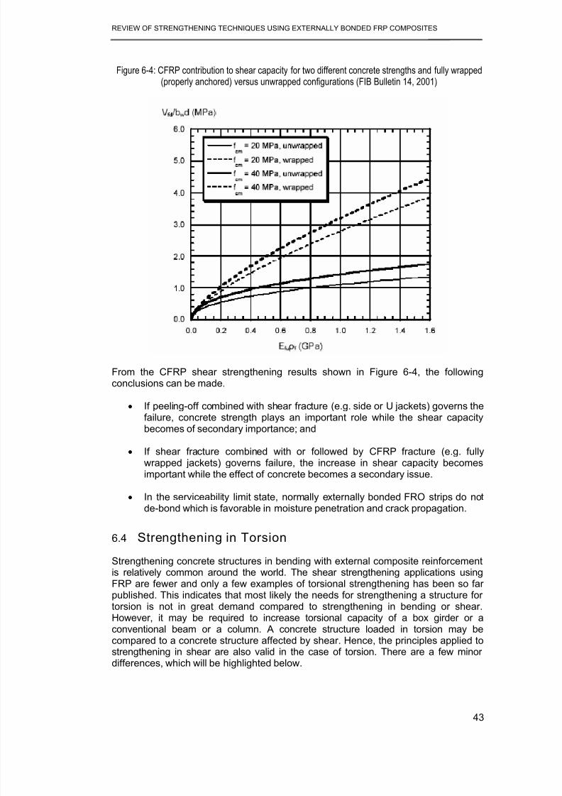
8/21/2019 Review of Strengthening Techniques Using Externally Bonded Fiber Reinforced Polymer Composites
http://slidepdf.com/reader/full/review-of-strengthening-techniques-using-externally-bonded-fiber-reinforced 51/67
REVIEW OF STRENGTHENING TECHNIQUES USING EXTERNALLY BONDED FRP COMPOSITES
43
Figure 6-4: CFRP contribution to shear capacity for two different concrete strengths and fully wrapped(properly anchored) versus unwrapped configurations (FIB Bulletin 14, 2001)
From the CFRP shear strengthening results shown in Figure 6-4, the followingconclusions can be made.
• If peeling-off combined with shear fracture (e.g. side or U jackets) governs thefailure, concrete strength plays an important role while the shear capacitybecomes of secondary importance; and
• If shear fracture combined with or followed by CFRP fracture (e.g. fullywrapped jackets) governs failure, the increase in shear capacity becomesimportant while the effect of concrete becomes a secondary issue.
• In the serviceability limit state, normally externally bonded FRO strips do notde-bond which is favorable in moisture penetration and crack propagation.
6.4 Strengthening in Torsion
Strengthening concrete structures in bending with external composite reinforcementis relatively common around the world. The shear strengthening applications usingFRP are fewer and only a few examples of torsional strengthening has been so farpublished. This indicates that most likely the needs for strengthening a structure fortorsion is not in great demand compared to strengthening in bending or shear.However, it may be required to increase torsional capacity of a box girder or aconventional beam or a column. A concrete structure loaded in torsion may becompared to a concrete structure affected by shear. Hence, the principles applied tostrengthening in shear are also valid in the case of torsion. There are a few minor
differences, which will be highlighted below.

8/21/2019 Review of Strengthening Techniques Using Externally Bonded Fiber Reinforced Polymer Composites
http://slidepdf.com/reader/full/review-of-strengthening-techniques-using-externally-bonded-fiber-reinforced 52/67
REVIEW OF STRENGTHENING TECHNIQUES USING EXTERNALLY BONDED FRP COMPOSITES
44
Cracks in concrete due to torsional loading usually follow the same mechanisms asconcrete cracking under shear loading. However it is important to understand how atorsional fracture develops. The main difference between shear and torsionalcracking, is that torsional crack forms a spiral patterns (Figure 6-5). The crack openswhen the principal strains exceed the tensile strength of the concrete. Thereforewhen the FRP system is placed in such a way that forms an angle with member axis,one side is more susceptible to diagonal cracking than the other. In designingtorsional strengthening using FRP, this point needs to be taken into account.
Figure 6-5: (a) Torsional and (b) shear cracking.
Back
Front
Top
θ
(a)
Back
Front
Top
θ
(b)
In the case of torsional strengthening of a concrete structure with fiber composites, itis assumed that the truss-model applies. However, the fiber composite is ananisotropic material. The placement of the fibers in relation to the principal straindirection must be considered. It is worth noting that only full wrapping schemearound the element’s cross section would provide increased torsional capacity, sothat the tensile forces carried by the FRP on each side of the cross section may forma continuous loop (Figure 6-6).
Figure 6-6: Forces carried by the FRP reinforcement
h
b
Ffd,v
Ffd,v
Ffd,h
Ffd,h

8/21/2019 Review of Strengthening Techniques Using Externally Bonded Fiber Reinforced Polymer Composites
http://slidepdf.com/reader/full/review-of-strengthening-techniques-using-externally-bonded-fiber-reinforced 53/67
REVIEW OF STRENGTHENING TECHNIQUES USING EXTERNALLY BONDED FRP COMPOSITES
45
7 AXIAL COMPRESSION, TENSION AND DUCTILITYENHANCEMENT
Until the early 1990s, constructing an additional reinforced concrete cage andinstalling grout injected steel jackets were the two common methods adopted forstrengthening of a deficient RC column (Ballinger et al. 1993). Steel jacketing is moreeffective than caging, because the latter results in substantial increase in the cross-section area and self weight of the structure. Both methods are however, laborintensive and sometimes difficult to implement on site. In recent years, using FRPcomposites as a technique to strengthen RC columns has replaced steel jacketing.
Several experimental studies on concrete confined with FRP (Saadatmanesh et al.1994, Nanni and Bradford 1995, Picher et al. 1996, Matthys et al. 1999, Candappa,2000) have been carried out which confirm using FRP as a method of strengthening.Current analytical and numerical research (Mirmiran and Shahawy 1997,
Saadatmanesh et al. 1994, Matthys et al. 1999, Lokuge et al., 2004) aims at definingthe constitutive behavior of FRP-confined members. The most common form of FRPcolumn strengthening involves the external wrapping of FRP sheets / straps.
The strengthening of RC columns using steel or FRP jacketing is based on the well-established fact that lateral confinement of concrete can substantially enhance itsaxial compressive strength and ductility. In seismic problems, strengthening orretrofitting techniques are based on increasing the confinement pressure in either thepotential plastic hinge region or over the entire member (e.g. Chai et al. 1991). In thefield of design of FRP jackets extensive experimental work has been conducted bySeible et al. (1995), and numerical and analytical work by Monti et al. (2001), with thetask of identifying suitable design equations that optimize the FRP jacket thickness
as a function of the desired upgrading level. It should be emphasized that usually theincrease in strength is not as significant as that in ductility. A recent review on theissue of upgrading through confinement may be found in Triantafillou (2001).
7.1 Axial Compression
Strength enhancement can be achieved by using steel confinement as well as FRPconfinement. However FRP-confined concrete behaves differently from steel-confined concrete. Therefore already established design guidelines for steel confinedconcrete columns cannot be applied for FRP confined columns. As shown in Figure7-1, the confinement actions provided by steel and FRP wrapping are different. This
behavior is due to the linear behavior (without any yield points) of carbon fibercomposites. After the initial linearly elastic phase, steel displays a yielding plateau.Therefore after reaching the maximum stress corresponding to yielding, the confiningpressure remains constant. In the contrary, FRP wrapping continues to providecontinuously increasing confining pressure until it fails (elastic behavior).
In designing the FRP strengthening system for columns, it is necessary to estimatethe strength enhancement of concrete due to FRP composite confinement. Thisconfining action depends on the strain in FRP composite which is same as the lateralstrain of concrete (lateral dilation). Therefore the passive confining pressure providedby the externally bonded FRP composites depends on the lateral dilation of concrete.Therefore constitutive model for concrete which can predict the lateral dilation of
concrete is ideal in estimating the passive confining pressure provided by the FRPcomposite. The concrete material model proposed by Lokuge et al., (2004), meets

8/21/2019 Review of Strengthening Techniques Using Externally Bonded Fiber Reinforced Polymer Composites
http://slidepdf.com/reader/full/review-of-strengthening-techniques-using-externally-bonded-fiber-reinforced 54/67
REVIEW OF STRENGTHENING TECHNIQUES USING EXTERNALLY BONDED FRP COMPOSITES
46
the above mentioned requirements. Moreover that model has been validated to givecomparable results for the experimental test results reported by Candappa (2000) forconcrete confined by FRP.
Figure 7-1: Comparison of confinement actions of steel and FRP materials (FIB Bulletin 14, 2001)
The maximum confining pressure provided by FRP composites is related to theamount and strength of FRP and the diameter of the confined concrete core.However, the ultimate strength of the confined concrete is closely related to thefailure strain of the FRP wrapping reinforcement. As the FRP is subjected to tensionin hoop direction, eventual failure occurs when its hoop tensile strength is reached.Many researchers (Lorenzis 2001) have noted that the strain measured in theconfining FRP at rupture is in many cases lower than the ultimate strain of FRPtested for tensile strength. The recorded hoop strains corresponding to rupture had arange of 50 to 80% of the failure strain obtained in the tensile tests (Xiao and Wu2000). This reduction is due to the following reasons:
• The triaxial state of stress of the wrapping reinforcement. The quality of theexecution
• If the surface preparation for FRP application is not good enough, some partof the circumferential strain is used to stretch the fibers. Moreover, fibers maybe damaged at improperly rounded edges or local protrusions
• The curve shape of the wrapping reinforcement
• Size effects when applying multiple layers
Figure 7-2 shows the concept of composite action, where the FRP jacketprovides longitudinal load carrying capacity as well as lateral confinement (itundergoes both longitudinal and lateral strains). This behavior depends on thefiber arrangement and bond interface characteristics. The ultimate stress andstrain are reduced with a possibility of micro-buckling and de-lamination.Therefore failure of the member occurs at a lower circumferential strain than incase of no composite action. In case of no composite action, the FRP jacket issubjected to lateral strain only and fails due to either fiber collapse or de-lamination between plies. This failure takes place at a circumferential strain lowerthan the ultimate strain.

8/21/2019 Review of Strengthening Techniques Using Externally Bonded Fiber Reinforced Polymer Composites
http://slidepdf.com/reader/full/review-of-strengthening-techniques-using-externally-bonded-fiber-reinforced 55/67
REVIEW OF STRENGTHENING TECHNIQUES USING EXTERNALLY BONDED FRP COMPOSITES
47
Figure 7-2: Triaxial state of stress in FRP jackets
Transverse compressive stress
when in composite action
Axial tensile stress due
to lateral expansion
Confining pressure
Depending on the loading condition (axial loading, shear and bending) the load-carrying capacity of the column should be calculated according to appropriate
confinement models.
7.2 Tensile Strengthening
FRP composites can be used to provide additional tensile strength to concretemembers. It depends on the design tensile strength of FRP and the ability to transferstress into the substrate (Nanni et al. 1998). The tensile strength contribution of FRPcan be directly calculated using Hooke’s law because of its linear-elastic behavior.
7.3 Ductility
The collapse of and severe damage to many buildings and bridges in recentearthquakes have highlighted the need for the seismic retrofit of seismicallyinefficient structures. Most of the structural failures during recent earthquakes wereattributed to poor column behavior. Figure 7-3 shows three photos of column failuresduring Kobe 1995 earthquake. These failures are due to inadequacy of confiningreinforcement and bad detailing, which resulted in improper confinement. In concretestructures, the ability to withstand strong earthquakes depends mainly on theformation of plastic hinges and their capability of energy absorption and dissipationwithout a major loss of strength capacity. Within the plastic hinge, all the inelasticdeformations are assumed to occur. The region outside the hinge is assumed toremain elastic at all times.
It is preferable to design structures with strong columns and weak beams with plastichinges forming in the beams and not in columns. However, it may not always bepossible to design structures like this, and hinges may develop in columns. Thereforethe possibility of plastic hinge formation at concrete column ends demands asufficient level of ductility to safeguard the structures in seismic areas. Therefore inperforming a structural analysis for earthquake loadings, it is of great importance todesign columns with sufficient level of ductility in order to minimize the chances of apossible failure.

8/21/2019 Review of Strengthening Techniques Using Externally Bonded Fiber Reinforced Polymer Composites
http://slidepdf.com/reader/full/review-of-strengthening-techniques-using-externally-bonded-fiber-reinforced 56/67
REVIEW OF STRENGTHENING TECHNIQUES USING EXTERNALLY BONDED FRP COMPOSITES
48
Figure 7-3: Column failures in Kobe 1995 earthquake (EQE 1995).
Using steel reinforcement is the traditional method of increasing ductility. Recentadvances in FRP technology have proven that FRP composites can be used to
increase the ductility of concrete columns. Methods of improving ductility using FRPcomposites are described here in brief (Triantafillou 2001).
The purpose of seismic retrofit of RC columns is to achieve a sufficient level ofdeformation ductility to dissipate seismic energy before one of the failure modesbecomes critical. The displacement ductility factor or the curvature ductility factor hasbeen commonly used to quantify the ductility of the seismic performance of astructure. In order to achieve a target displacement ductility factor, µ ∆, it is possible tofind the thickness of the FRP jacket. The method is explained in FIB Bulletin 14, 2001and is as follows.
Equivalent plastic hinge length Lp for a given column is calculated based on the yieldstress and diameter of longitudinal rebars.
From Lp and µ ∆ the curvature ductility factor µΦ = Φu / Φy is established.
Curvature ductility factor µΦ = Φu / Φy . Φy is the yield curvature and it may be foundfrom moment-curvature analysis of the cross section, whereas Φu is the maximumcurvature and it may be obtained (again from section analysis) in terms of theultimate concrete strain.
Therefore ultimate concrete strain can be established and an appropriateconfinement model can be used to determine the required FRP thickness.
Japanese researchers (Mutsuyoshi et al. 1999) have used a different method inestimating the displacement ductility factor for FRP confined columns. They havefound that displacement ductility factor is related to the shear capacity Vu, and to themoment capacity Mu of the member after retrofitting.

8/21/2019 Review of Strengthening Techniques Using Externally Bonded Fiber Reinforced Polymer Composites
http://slidepdf.com/reader/full/review-of-strengthening-techniques-using-externally-bonded-fiber-reinforced 57/67
REVIEW OF STRENGTHENING TECHNIQUES USING EXTERNALLY BONDED FRP COMPOSITES
49
8 USE OF FRP BARS AS PRIMARY REINFORCEMENT
Providing steel reinforcement in reinforced concrete structures is a commonly andtraditionally used method to resist the tensile stresses. However, these steel bars cancorrode due to various reasons. Improper design and workmanship, cover
insufficiency can lead to cracking of concrete and adverse environmental conditionscan ultimately lead to corrosion of steel bars. Corrosion of steel reinforcement inconcrete structures (chloride ion or chemical corrosion) result in deterioration of thestructures, costly maintenance and repair and reduction of the service life of thestructure. Limited life span of reinforced concrete structures has been addressed inthe past and a necessity arises to investigate methods of prevention of corrosion oruse of non-corrosive reinforcement.
Fiber Reinforce Polymer (FRP) bars have been identified as a prospective substitutefor steel reinforcement as FRP materials are nonmetallic, non-corrosive and theyhave a high tensile strength and are light weight. The commonly used FRP bars areCFRP, GFRP and AFRP. Apart from using FRP instead of steel reinforcement, it has
been proposed that they can be used as steel pre-stressing tendons in pre-stressedconcrete structures (ACI 440R 1996). It is reported that FRP is used in situationswhere electrical or magnetic transparency is required (FRP Reinforcing Bar website). FRP bars have been identified as a promising solution to the corrosionproblems associated with steel reinforcement in concrete structures. They can beused in marine structures, parking structures, bridge structures under adverseenvironmental conditions and where magnetic fields are present.
Standards and design guidelines for the provision of FRP bars in concrete structuresfor bridges and buildings have been prepared recently (ACI 440H 2000; CSA 2000;ISIS-Canada, 1998 and 2001, CEM, 2002).
Fiberglass rebar may be a suitable alternative to steel reinforcing as shown in CEM(2002):
• Architectural Concrete: cast stone, architectural cladding, balusters, columnfacades, window lentils, architectural pre-cast elements, hand railing, andstatuary and fountains, etc.
• Concrete exposed to de-icing salts in: bridge decks, railroad grade crossings,median barriers, parking garage elements, and salt storage facilities, etc.
• Concrete exposed to marine salts in: seawalls, water breaks, buildings &structures near waterfront, aquaculture operations, and floating marine docks,etc.
• Concrete used near electromagnetic equipment such as: MRI rooms inhospitals, airport radio & compass calibration pads, and concrete near highvoltage cables, transformers, substations, etc.

8/21/2019 Review of Strengthening Techniques Using Externally Bonded Fiber Reinforced Polymer Composites
http://slidepdf.com/reader/full/review-of-strengthening-techniques-using-externally-bonded-fiber-reinforced 58/67
REVIEW OF STRENGTHENING TECHNIQUES USING EXTERNALLY BONDED FRP COMPOSITES
50
Figure 8-1 shows use of GFRP rebars in construction of Sierrita de la Cruz CreekBridge, RM1061 Amarillo Texas.

8/21/2019 Review of Strengthening Techniques Using Externally Bonded Fiber Reinforced Polymer Composites
http://slidepdf.com/reader/full/review-of-strengthening-techniques-using-externally-bonded-fiber-reinforced 59/67
REVIEW OF STRENGTHENING TECHNIQUES USING EXTERNALLY BONDED FRP COMPOSITES
51
Figure 8-1: Use of GFRP rebars in construction of Sierrita de la Cruz Creek Bridge,
RM1061 Amarillo Texas (Aslan FRP, 2004)
8.1 Applications of FRP barsFRP bars have been originally applied as non-magnetic or radio-frequencytransparent reinforcements for magnetic resonance imaging (MRI) medicalequipment and for specialized defense applications. FRP composite rebar applicationhas emerged about twenty five years ago. Deterioration of the concrete structureshas lead US, Europe and Japan to investigate FRP composite rebar as an alternativeto steel reinforcement. According to ACI 440H, the Japanese lead in this field, withmore than 100 demonstration projects reported in the literature. Publication of ACI440.1R-01 Guide for the Design and Construction for Concrete Reinforced withFRP bars paved the way for practicing engineers to use this newly developed FRPbars.

8/21/2019 Review of Strengthening Techniques Using Externally Bonded Fiber Reinforced Polymer Composites
http://slidepdf.com/reader/full/review-of-strengthening-techniques-using-externally-bonded-fiber-reinforced 60/67
REVIEW OF STRENGTHENING TECHNIQUES USING EXTERNALLY BONDED FRP COMPOSITES
52
8.2 Design Considerations
A direct substitution of FRP reinforcing bars instead of steel bars is impossible due tomany differences in the mechanical properties of the two materials. Fiber reinforcedpolymer bars are anisotropic materials. Factors such as type and volume of fiber and
resin, fiber orientation and quality control during the manufacturing play a major rolein the mechanical characteristics.
• FRP composites show a linear elastic behavior until failure and no ductility.This is contrary to the steel which shows yielding.
• ACI Committee 440 recommends a minimum amount of FRP rebar. Theconcrete will be the weak link and the member will fail in concrete crushing incompression. At this stage FRP will still hold a good tensile strength. Intraditional steel reinforcement design, steel yielding prior to crushing ofconcrete is ensured by provisions in standard design codes.
• Another major difference is that serviceability will be more of a designlimitation in FRP reinforced members than in steel reinforced members. Dueto its lower modulus of elasticity, deflection and crack width will affect thedesign. Deflection and crack width serviceability requirements will provideadditional warning of failure prior to compression failure of the concrete.
• Service limits in FRP reinforced concrete elements such as deflection, crackwidth and crack spacing are directly influenced by the bond properties of thereinforcement in concrete.
• FRP reinforced concrete member is normally designed based on its requiredstrength and then checked for serviceability and ultimate state criteria (e.g.,
crack width, deflection, fatigue and creep rupture endurance).

8/21/2019 Review of Strengthening Techniques Using Externally Bonded Fiber Reinforced Polymer Composites
http://slidepdf.com/reader/full/review-of-strengthening-techniques-using-externally-bonded-fiber-reinforced 61/67
REVIEW OF STRENGTHENING TECHNIQUES USING EXTERNALLY BONDED FRP COMPOSITES
53
9 SUMMARY OF THE STRENGTHENINGTECHNIQUES
Table 9-1 presents summary of strengthening techniques, which are covered in this
report. The type of FRP, design actions and special need of each technique are alsotabulated.
Table 9-1: Summary of strengthening techniques
Strengthening Method Design ActionType of
FRPSpecial
Considerations
Wet lay up of FRP sheets tothe tension zone of the soffit of
a beam or slab
Flexuralstrengthening
Sheets orstrips
De-bonding
Attaching prefabricated FRPsheets to the tension zone ofthe soffit of a beam or slab
Flexuralstrengthening
Sheets orstrips
De-bonding
The different types of wrappingschemes to increase the shearstrength of a beam or column
Shearstrengthening
SheetsDirection of
fibres
Automated winding of wetfibers under a slight anglearound columns or other
structures,
Shear and axialcompressionstrengthening
SheetsEquipmentavailability
Attaching prestressed FRPstrips to the tension zone of
the soffit of a beam or slab
Flexural
strengthening
Strips Anchorage
Fusion-bonded pin-loadedstraps
Flexural and shearstrengthening
Pin-loadedStraps
Equipmentavailability
In-situ fast curing usingheating device
Flexuralstrengthening
Strips -
Prefabricated U or L shapestrips for shear strengthening
Shearstrengthening
StripsDirection of
fibres
Bonding FRP strips insideconcrete slits
Flexuralstrengthening
Strips Crack initiation
FRP impregnation by vacuum
to the tension zone of the soffitof a beam or slab
Flexural
Strengthening Strips
Equipment
availability
Prefabricated FRP shells or jackets for the confinement ofcircular or rectangular columns
Axial compressionstrengthening and
ductilityenhancement
Sheets
Confiningpressure will bedifferent to that
of steel
FRP wrapping for axialcompression strengtheningand ductility enhancement
Axial compressionstrengthening and
ductilityenhancement
SheetsConfining
pressure will bedifferent
FRP wrapping for torsionalstrengthening
Torsionalstrengthening
SheetsDirection of
fibres

8/21/2019 Review of Strengthening Techniques Using Externally Bonded Fiber Reinforced Polymer Composites
http://slidepdf.com/reader/full/review-of-strengthening-techniques-using-externally-bonded-fiber-reinforced 62/67
REVIEW OF STRENGTHENING TECHNIQUES USING EXTERNALLY BONDED FRP COMPOSITES
54
10 REFERENCES
American Concrete Institute Committee 440, (2002). “Guide for the design andconstruction of externally bonded FRP systems for strengthening concretestructures”
Arduini, M. and Nanni, A. (1997) “Behavior of precracked RC beams strengthenedwith FRP sheets” Journal of Composites for Constructions, ASCE, Vol. 1, No. 2,pp. 63-70
Bakis, C.E.; Bank, L.C.; Brown, V.L.; Cosenza, E.; Davalos, J.F.; Lesko, J.J.;Machida, A.; Rizkalla, S.H.; and Triantifillou, T.C. 2002 “Fiber-ReinforcedPolymer Composites for Construction-State-of-the-Art Review,” Journal ofComposites in Construction, V. 6, No. 2, pp. 73-87.
Ballinger, C., Maeda, T. and Hoshijima, T. (1993) “Strengthening of reinforcedconcrete chimneys, columns and beams with carbon fiber reinforced plastics”Proceedings of the International Symposium on Fiber-Reinforced-PlasticReinforcements for Concrete Structures, ACI SP-138, pp. 243-248
Benmokrane, B., and Rahman, H., Eds., 1998, Durability of Fiber Reinforced
Polymer (FRP) Composites for Construction, University of Sherbrooke,Canada.
Blaschko, M. and Zilch, K. (1999), “Rehabilitation of concrete structures with CFRPstrips glued into slits” Proceedings of the 12th International Conference onComposite Materials, Paris, July 5-9.
Bonacci, J.F. and Maalej, M. (2000) “Externally bonded fiber-reinforced polymer forrehabilitation of corrosion damaged concrete beams” ACI Structural Journal,Vol. 97, No.5, pp. 703-711
Buyukozturk, O. and Hearing, B. (1998) “Failure behavior of precracked concretebeams retrofitted with FRP” Journal of Composites for Construction, ASCE, Vol.2, No. 3, pp. 138-144
Candappa, D. (2000). “The constitutive behavior of high strength concrete underlateral confinement, PhD thesis, Monash University, Australia.
CEM (2002), “FRP Rebar”, Emerging Construction Technologies, <http://www.new-technologies.org/ECT/Civil/frprebar.htm> (June 30, 2004).
Chai, Y. H., Priestley, M. J. N. and Seible, F. (1991), “Seismic retrofit of circularbridge columns for enhanced flexural performance”, ACI Structural Journal,88(5), 572-584
Chajes, M.; Januska, T.; Mertz, D.; Thomson, T.; and Finch, W., 1995, “ShearStrengthening of Reinforced Concrete Beams Using Externally AppliedComposite Fabrics,” ACI Structural Journal, V. 92, No. 3, pp. 295-303.
Deuring, M. (1993), “Strengthening of RC with prestressed fiber reinforced plasticsheets”, EMPA Research Report 224, Dübendorf, Switzerland (in German).
Dolan, C.W., Rizkalla, S.H., and Nanni, A. (Editors), 1999, Fourth InternationalSymposium on Fiber Reinforced Polymer Reinforcement for ReinforcedConcrete Structures. American Concrete Institute, SP-188, Farmington Hills,Michigan.
EQE (1995). “The January 17, 1995 Kobe Earthquake." EQE Summary Report,<http://www.eqe.com/publications/kobe/building.htm> (October 22, 2003).
Fardis, M.N., and Khalili, H., 1981, “Concrete Encased in Fiberglass ReinforcedPlastic,” ACI Journal, 78(6), pp. 440-446.
FIB Bulletin 14, 2002, “Externally bonded FRP reinforcement for RC structures”, Taskgroup 9.3, International Federation of Structural Concrete (FIB).
Fleming, C.J., and King G.E.M., 1967, “The Development of Structural Adhesives forThree Original Uses in South Africa”, RILEM International Symposium,
Synthetic Resins in Building Construction, Paris, pp.75-92.FRP Reinforcing Bar web site, http://www.cif.org/Nom2003/Nom04_03.pdf

8/21/2019 Review of Strengthening Techniques Using Externally Bonded Fiber Reinforced Polymer Composites
http://slidepdf.com/reader/full/review-of-strengthening-techniques-using-externally-bonded-fiber-reinforced 63/67
REVIEW OF STRENGTHENING TECHNIQUES USING EXTERNALLY BONDED FRP COMPOSITES
55
GangRao, H.V.S., and Vijay, P.V. (1998) “Bending Behavior of Concrete BeamsWrapped with Carbon Fabric” Journal of Structural Engineering, V.124, No.1,pp. 3-10
Garden H.N., Hollaway, L.C. and Thorne, A.M. (1997) “ A preliminary evaluation ofcarbon fiber reinforced polymer plates for strengthening reinforced concretemembers” Proceeding of the institute of Civil Engineers: Structures andBuildings , Vol. 123, May, pp. 127-142
Grace, N.F., Soliman, A.K., Abdel-Sayed, G. and Saleh, K. R. (1998) “Behavior andductility of simple and continuous beams using FRP reinforced beams” Journalof Composites for Construction, ASCE, Vol. 2, No.4, pp. 186-194
Aslan FRP (2004), “Bridges and Transportation Structures”, Hughes Brothers, Inc.,<http://www.hughesbros.com/Aslan100/Aslan%20GFRP%20Bridges.html>(June 30, 2004).
ISIS Canada Design Manuals, 2001, “Strengthening Reinforced Concrete Structureswith Externally-Bonded Fibre Reinforced Polymers,” The Canadian Network ofCentres of Excellence on Intelligent Sensing for Innovative Structures,Winnipeg, MB, Canada, 86 pp.
ISIS, 1998, ISIS Standard Test Methods, University of Manitoba, Winnipeg,Manitoba.Japan Concrete Institute (JCI), 1997, Non-metallic (FRP) Reinforcement for Concrete
Structures, 1 and 2, Tokyo, Japan.Japan Concrete Institute (JCI), 1998, “Technical Report on Continuous Fiber
Reinforced Concrete,” TC 952: Committee on Continuous Fiber reinforcedConcrete, Tokyo.
Japan Society of Civil Engineers (JSCE), 2001, “Recommendations for Upgrading ofConcrete Structures with Use of Continuous Fiber Sheets,” ConcreteEngineering Series, No. 41, Tokyo, Japan, 250 pp.
Kachlakev, D., and McCurry, D., 2000, “Testing of Full-Size Reinforced ConcreteBeams Strengthened with FRP Composites: Experimental Results and Design
Methods Verification,” Report No. FHWA-OR-00-19, U.S. Department ofTransportation Federal Highway Administration
Katsumata, H.; Kobatake, Y.; and Takeda, T., 1987, “A Study on the Strengtheningwith Carbon Fiber for Earthquake-Resistant Capacity of Existing ConcreteColumns,” Proceedings from the Workshop on Repair and Retrofit of ExistingStructures, U.S.-Japan Panel on Wind and Seismic Effects, U.S.-JapanCooperative Program in Natural Resources, Tsukuba, Japan, pp. 1816-1823.
Lokuge, W. P., Sanjayan, J. G., and Setunge, S. (2004). “Stress strain model forlaterally confined concrete", Approved for publication in the Journal of Materialsin Civil Engineering, ASCE.
Lorenzis, L. D. (2001). “A comparative study of models on confinement of concretecylinders with FRP composites" Research report, Chalmers University of
Technology, Goteborg, Sweden.Luke, P. S., Leeming, M. B. and Skwarski, A. J. (1998), “ROBUST results for carbon
fibre”, Concrete Engineering International, 2(2), 19-21.Malvar, L., 1998, “Durability of Composites in Reinforced Concrete,” Proceedings of
the First International Conference on Durability of Composites for Construction, Aug., Sherbrooke, Canada, pp. 361-372.
Malvar, L.; Warren, G.; and Inaba, C., 1995, “Rehabilitation of Navy Pier Beams WithComposite Sheets,” Second FRP International Symposium, Non-Metallic (FRP)Reinforcements for Concrete Structures, Aug., Gent, Belgium, pp. 533-540.
Mandell, J.F., 1982, “Fatigue Behavior of Fibre-Resin Composites,” Developments inReinforced Plastics, Applied Science Publishers, London, England, V. 2, pp.67-107.
Master Builders Technologies (MBT), Australia, MBrace Design CD ROM, Version3.0.

8/21/2019 Review of Strengthening Techniques Using Externally Bonded Fiber Reinforced Polymer Composites
http://slidepdf.com/reader/full/review-of-strengthening-techniques-using-externally-bonded-fiber-reinforced 64/67
REVIEW OF STRENGTHENING TECHNIQUES USING EXTERNALLY BONDED FRP COMPOSITES
56
Matthys, S., Taerwe, L. and Audenaert, K. (1999), “Tests on axially loaded concretecolumns confined by FRP sheet wrapping”, Proceedings of the 4th InternationalSymposium on FRP for Reinforced Concrete Structures, Baltimore, USA, 217-228.
Meier, U., 1987, “Bridge Repair with High Performance Composite Materials,”Material und Technik, V. 4, pp. 125-128 (in German)
Meier, U., 1995, “Strengthening of structures using carbon fiber/epoxy composites,”Construction and Building Materials, Vol. 9, No. 6, pp. 341-351
Mirmiran, A. and Shahawy, M., (1997), “Behavior of concrete columns confined byfiber composites”, Journal of Structural Engineering, ASCE, 123(5), 583-590
Monti, G., Nisticò, N. and Santini, S. (2001), “Design of FRP jackets for upgrade ofcircular bridge piers”, Journal of Composites for Construction, ASCE, in print
Mutsuyoshi, H., Ishibashi, T., Okano, M. and Katsuki, F. (1999), “New design methodfor seismic retrofit of bridge columns with continuous fiber sheet –Performance-based design”, Fiber Reinforced Polymer Reinforcement forReinforced Concrete Structures, ed. C. W. Dolan, S. H. Rizkalla and A. Nanni, ACI Report SP-188. Detroit, Michigan, 229-241.
Nanni, A. and Bradford, N. M. (1995), “FRP jacketed concrete under uniaxialcompression”, Construction and Building Materials, 9(2), 115-124Nanni, A., 1995, “Concrete Repair with Externally Bonded FRP Reinforcement”,
Concrete International, Vol. 17 No.6, pp.22-26Nanni, A.; Focacci, F.; and Cobb, C.A., 1998, “Proposed Procedure for the Design of
RC Flexural Members Strengthened with FRP Sheets,” Proceedings, ICCI-98,Jan., Tucson, Ariz, V. 1, pp. 187-201
National Research Council, 1991, “Life Prediction Methodologies for CompositeMaterials,” Committee on Life Prediction Methodologies for Composites,NMAB-460, National Materials Advisory Board, Washington D.C.
Neale, K.W., 2000, “FRPs for Structural Rehabilitation: A Survey of RecentProgress,” Progress in Structural Engineering and Materials, Vol. 2, No. 2, pp.
133-138Nguyen, D.M., Chan, T.K. and Cheong, H.K. (2001) “Brittle failure and bond
development length of CFRP-concrete beams” Journal of Composites forConstruction, ASCE, Vol. 5, No.1, pp. 12-17
Norris, T.; Saadatmanesh, H.; and Ehsani, M., 1997, “Shear and FlexuralStrengthening of R/C Beams with Carbon Fiber Sheets,” Journal of StructuralEngineering, V. 123, No. 7, pp. 903-911
Nystrom, H. E., Walkins, S. E., Nanni, A., and Murray, S. (2003). “ Financial Viabilityof Fiber-Reinforced Polymer (FRP) Bridges” Journal of Management inEngineering, Vol. 19 No. 1 pp. 2-8
Odagiri, T.; Matsumoto, K.; and Nakai H., 1997, “Fatigue and RelaxationCharacteristics of Continuous Aramid Fiber Reinforced Plastic Rods,” Third
International Symposium on Non-Metallic (FRP) Reinforcement for ConcreteStructures (FRPRCS-3), Japan Concrete
Picher, F., Rochette, P. and Labossière, P. (1996), “Confinement of concretecylinders with CFRP”, Proceedings of 1st International Conference onComposite Infrastructures, Tucson, Arizona, USA, 829-841
Quantrill, R.J., Hollaway, L.C. and Thorne, A.M. (1996) “Experimental and analyticalinvestigation of FRP strengthened beam response: Part I” Magazine ofConcrete Research, Vol. 48, No.177, pp. 331-342
Rahimi, H. and Huchinson, A. (2001) “Concrete beams strengthened with externallybonded FRP plates” Journal of Composites for Construction, ASCE, Vol. 5,No.1, pp. 44-56
Railway Technical Research Institute (RTRI), 1996, “Design and ConstructionGuidelines for Seismic Retrofitting of Railway Viaduct Columns Using AramidFiber Sheets,” Tokyo (in Japanese)

8/21/2019 Review of Strengthening Techniques Using Externally Bonded Fiber Reinforced Polymer Composites
http://slidepdf.com/reader/full/review-of-strengthening-techniques-using-externally-bonded-fiber-reinforced 65/67
REVIEW OF STRENGTHENING TECHNIQUES USING EXTERNALLY BONDED FRP COMPOSITES
57
Railway Technical Research Institute (RTRI), 1996, “Design and ConstructionGuidelines for Seismic Retrofitting of Railway Viaduct Columns Using CarbonFiber Sheets,” Tokyo (in Japanese)
Ramana, V.P.V., Kant, T., Morton, S.E., Dutta, P.K., Mukherjee, A. and Desai, Y.M.(2000) “Behavior of CFRPC strengthened reinforced concrete beams withvarying degrees of strengthening” Composites, Part B, Vol. 31, pp. 461-470
Ritchie, P.A., Thomas, D.A., Lu, L.W. and Connely, G.M. (1991) “Externalreinforcement of concrete beams using fiber reinforced plastics” ACI StructuralJournal, Vol. 88, No.4, pp. 490-500
Ross, C.A., Jerome, D.M., Tedesco, J.W. and Hughes, M.L. (1999) “Strengtheningreinforced concrete beams with externally bonded steel plates” ACI StructuralJournal, Vol. 96, No.2, pp. 212-220
Rostasy, F.S., 1987, “Bonding of Steel and GFRP Plates in the Area of CouplingJoints. Talbrucke Kattenbusch.”, Research Report No. 3126/1429, FederalInstitute for Materials Testing, Braunschweig, Germany (in German).
Roylance, M., and Roylance, O., 1981, “Effect of Moisture on the Fatigue Resistanceof an Aramid-Epoxy Composite,” Organic Coatings and Plastics Chemistry,
American Chemical Society, Washington, D.C., V. 45, pp. 784-788.Saadatmanesh, H., and Ehsani, M., ed., 1998, Second International Conference onComposites in Infrastructure, ICCI, Tucson, Ariz., V. 1 & 2, 1506 pp.
Saadatmanesh, H., Ehsani, M. R. (1991), “RC beams strengthened with GFRPplates. I: experimental study”, Journal of Structural Engineering, Vol. 117, No.11, pp. 3417-3433
Saadatmanesh, H., Ehsani, M. R. and Li, M. W. (1994), “Strength and ductility ofconcrete columns externally reinforced with fiber composite straps”, ACIStructural Journal, 91(4), 434-447
Sato, Y.; Ueda, T.; Kakuta, Y.; and Tanaka, T., 1996, “Shear Reinforcing Effect ofCarbon Fiber Sheet Attached to Side of Reinforced Concrete Beams,” Advanced Composite Materials in Bridges and Structures, M.M. El-Badry, ed.,
pp. 621-627Seible, F., Burgueño, R., Abdallah, M. G. and Nuismer, R. (1995 b), “Advanced
composite carbon shell systems for bridge columns under seismic loadsProgress in research and practice”, Proceedings of National SeismicConference on Bridges and Highways, San Diego, CA, USA.
Seible, F., Priestley, M. J. N. and Innamorato, D. (1995 a), “Earthquake retrofit ofbridge columns with continuous fiber jackets” Design guidelines, Advancedcomposite technology transfer consortium, 2, Report No. ACTT-95/08,University of California, San Diego, USA
Shahawy, M.A., Arockiasamy, M., Beitelman, T. and Sowrirajan, R. (1996)“Reinforced concrete beams strengthened with CFRP laminates” Composites,Part B, Vol. 27B, pp. 225-233
Sharif, A., Al-Sulaimani, G.J., Basunbul, I.A., Baluch, M.H. and Ghaleb, B.N. (1994)“Strengthening of initially loaded reinforced concrete beams using FRP plates” ACI Structural Journal, Vol. 91, No.2, pp. 160-168
Sheheta, E.; Morphy, R.; and Rizkalla, S., 1999, Fourth International Symposium,Fiber Reinforced Polymer Reinforcement for Concrete Structures, SP-188, American Concrete Institute, Farmington Hills, Mich., pp. 157-167.
Sika CarboDur Composite Strengthening Systems, Australia, CD ROM.Spadea, G., Bencardino, F. and Swamy, R.N. (1998) “Structural behavior of
composite RC beams with externally bonded CFRP” Journal of Composites forConstruction, ASCE, Vol. 2, No.3, pp. 132-137
Spadea, G., Bencardino, F. and Swamy, R.N. (2000) “Optimizing the performancecharacteristics of beams strengthened with bonded CFRP laminates” Materialsand structures, Vol. 33, pp. 119-126

8/21/2019 Review of Strengthening Techniques Using Externally Bonded Fiber Reinforced Polymer Composites
http://slidepdf.com/reader/full/review-of-strengthening-techniques-using-externally-bonded-fiber-reinforced 66/67
REVIEW OF STRENGTHENING TECHNIQUES USING EXTERNALLY BONDED FRP COMPOSITES
58
Swamy, R.N. and Mukhopadhyaya, P. (1999) “Debonding of carbon-fiber-reinforcedpolymer plate from concrete beams” Proceeding of the institution of CivilEngineers: Structures and Buildings, Vol. 134, November, pp. 301-317
Takeda, K., Mitsui, Y., Murakami, K., Sakai, H. and Nakamura, M. (1996) “Flexuralbehavior of reinforced concrete beams strengthened with carbon fiber sheets” Composites, Part A, Vol. 27A, pp. 981-987
Täljsten, B. and Elfgren, L. (2000), “Strengthening concrete beams for shear usingCFRP materials, Evaluation of different application methods”, Journal ofComposites, Part B, accepted for publication.
Triantafillou, T. C. (1998), “Shear strengthening of reinforced concrete beams usingepoxy bonded FRP composites” ACI Structural Journal, 95(2), 107-115.
Triantafillou, T. C. (2001), “Seismic retrofitting of structures using FRPs. Progress inStructural Engineering and Materials”, 3(1), in print.
Triantafillou, T. C. and Antonopoulos, C. P. (2000), “Design of concrete flexuralmembers strengthened in shear with FRP”. ASCE Journal of Composites forConstruction, 4(4), 198- 205.
Triantafillou, T. C. and Plevris, N. (1992), “Strengthening of RC beams with epoxy-
bonded fibre-composite materials”, Materials and Structures, 25, 201-211.Triantafillou, T. C., Deskovic, N. and Deuring, M. (1992), “Strengthening of concretestructures with prestressed fiber reinforced plastic sheets”, ACI StructuralJournal, 89(3), 235-244.
Varastehpour, H. and Hamelin, P. (1997) “Strengthening of concrete beams usingfiber reinforced plastics” Materials and Structures, Vol. 30, pp. 160-166
Vecchio, F.J. and Bucci, F. (1999) “ Analysis of repaired reinforced concretestructures” Journal of Composites for Construction, ASCE, Vol. 125, No.6, pp.644-652
Wolf R. and Miessler H. J. (1989) HLV-Spannglieder in der praxis, erfahrungen mitglasfaserverbundstaben. Beton, 2, pp.47-51.
Xiao, Y. and Wu, H. (2000) “Compressive behavior of concrete confined by carbon
fiber composite jackets" Journal of Materials in Civil Engineering, Vol. 12, No. 2,pp. 139-146.
Yamaguchi, T.; Kato, Y.; Nishimura, T.; and Uomoto, T., 1997, “Creep Rupture ofFRP Rods Made of Aramid, Carbon and Glass Fibers,” FRPRCS-3, ThirdInternational Symposium on Non-Metallic FRP Reinforcement for ConcreteStructures, Sapporo, Japan, V. 2, pp. 179-186.

8/21/2019 Review of Strengthening Techniques Using Externally Bonded Fiber Reinforced Polymer Composites
http://slidepdf.com/reader/full/review-of-strengthening-techniques-using-externally-bonded-fiber-reinforced 67/67
REVIEW OF STRENGTHENING TECHNIQUES USING EXTERNALLY BONDED FRP COMPOSITES
11. Author Biographies
Dr Abe Nezamian,
Education: PhD, Monash University, Australia 2003, B.Sc. (Hons) Azad University, Iran 1990
Professional Experience: Nine years of experience in consulting engineeringcompanies.
Research Interests: Rehabilitation of aged concrete structures, compositestructures, and concrete filled tubular steel columns
Dr Sujeeva Setunge,
Education: PhD, Monash University, Australia (1993), B.Sc.Eng.(Hons) Sri Lanka (1985)
Professional Experience: 1 year in Civil Engineering Construction and 15 years in Academia.
Research Interests: Infrastructure asset management, creep and shrinkageof concrete, innovative construction materials andcomposites, high strength and high performanceconcrete
Dr Weena Lokuge,
Education: PhD, Monash University, Australia (2003), M.Eng, Asian Institute of Technology, Thailand (1997), B.Sc.(Hons) Sri Lanka (1994)
Professional Experience: 9 years in academia and one year in design
Research Interests: Constitutive behaviour of concrete, life cycle analysis,structural dynamics