review of the practical effectiveness of thin spray-on liners based … · review of the practical...
TRANSCRIPT
Mining Geomechanical Risk 2019 – J Wesseloo (ed.) © 2019 Australian Centre for Geomechanics, Perth, ISBN 978-0-9876389-1-5
Mining Geomechanical Risk 2019, Perth, Australia 443
Review of the practical effectiveness of thin spray-on liners based on information from suppliers and observations from the mining industry
MJ Kanda University of the Witwatersrand, South Africa
TR Stacey University of the Witwatersrand, South Africa
Abstract Thin spray‐on liners (TSLs) provide areal support to rock excavation surfaces, and have been implemented in the mining sector for over 20 years. However, scepticism over their usage still prevails, despite the results of laboratory research that has been carried out indicating their effectiveness for use in mines. The study described in this paper aims to highlight TSL performance as viewed by the mining industry. Some underground cases of practical performance have been singled out and compared with the expected performance based on information from suppliers and from laboratory testing perspectives, and the causes of the resulting quality of performances were categorised. Among the causes of the discrepancies between expectations and observations is the lack of inclusion of parameters such as temperature and humidity in the laboratory tests, which could have significant effects on the liner performance since, based on results from Brazilian indirect tensile tests on coated samples, their inclusion doubles the probability of failure and therefore, increases the predicted geotechnical risk of failure. Consequently, to take into account potential performance discrepancies, some existing recommendations and further potential recommendations are suggested in the paper. If later validated, these suggestions could be included in a good practice guideline for TSL application in underground mines.
Keywords: thin spray‐on liners, tensile strength, membrane displacement test, suppliers, laboratory, mining, response surface methodology, probability of failure, geotechnical risk
1 Introduction Thin spray‐on liners (TSLs) have been the most recent areal support method used in the mining environment in South Africa. Their effectiveness is controversial because, though highly rated by some suppliers and some results from laboratories, their performances are yet to meet the expectation of the sceptical users in the mining industry. TSLs are therefore not resorted to when substantial support performances are needed. Strong practical evidence of their performance or non‐performance needs to be produced to demonstrate their capabilities and limitations definitively. Through this approach, it would therefore be possible to dissipate the scepticism and to provide best‐practice guidelines. TSL properties have been estimated and measured in the laboratory and generally show higher tensile strengths than shotcrete (Yilmaz 2014). This mechanical property, along with the elongation strength and the tensile bond strength, have been indicated by Potvin et al. (2004) to be the most important mechanical properties of thin membranes. Thus, the research described in this paper will focus on them when reviewing the practical performance of TSLs from the viewpoints of the suppliers, the laboratory and the mining industry.
https://papers.acg.uwa.edu.au/p/1905_27_Kanda/

Review of the practical effectiveness of thin spray-on liners based on MJ Kanda and TR Stacey information from suppliers and observations from the mining industry
444 Mining Geomechanical Risk 2019, Perth, Australia
2 Thin spray-on liner effectiveness based on information from suppliers and laboratory testing
This research will focus on the tensile strength, the adhesion strength (here assessed as the factor of enhancement of the strength of a Brazilian indirect tensile (BIT) specimen), and representative properties encountered in the membrane displacement test (MBT), namely elongation, tear, tensile and adhesive properties.
2.1 Tensile strength The preparation of TSL dogbone tensile test specimens, particularly for brittle TSLs referred to in this paper, required the use of moulds made of perspex rather than to the stamping process with die cutting moulds. The latter mode of preparation was suggested by Tannant et al. (1999), Archibald and DeGagné (2000) and Guner and Ozturk (2017). These researchers recommended that the use of die cut dogbone specimens be favoured, especially for tensile creep tests, since they produced less scatter in the results and higher strength values than moulded specimens. However, their experience was with ductile TSLs, while Yilmaz (2010) focused on cementitious TSLs which are brittle. Therefore, brittle TSLs should be prepared with moulds while ductile TSLs specimens should be prepared using die cutters. However, prior to adopting these guidelines, some basic requirements have to be observed with regard to specimen preparation and test execution (ASTM 2010; Yilmaz 2010):
TSL performance is dictated by the diligence in preparing the mixtures, the obtention of adequate texture, the timing between the preparation of the coating and its application, and the atmospheric conditions at the time of specimen preparation (two technicians may prepare and apply TSLs from the same supplied bag of TSL, in the same laboratory, but may obtain different strength quality results).
A tensile test (dogbone) will only be valid when the specimen fails at the narrow section.
When resorting to a testing machine, efficient tensile trials require, an initial loading rate be of about 2.5 N/s and it should be applied for approximately 40 sec before the start of the tensioning process at the rate of 5 N/s until failure occurs.
In accordance with these guidelines, Yilmaz (2010) suggested that after 28 curing days, the strength of strong and very strong TSLs should range from 3.5–9 MPa. Table 1 displays the tensile strengths of some thin coating materials, as given by suppliers, and the mean values obtained from laboratory testing after 28 days. Laboratory tests were also undertaken on TSLs with curing times extended to 224 days to assess their behaviour beyond the recommended curing times. In each case, at least 10 tensile trials were performed.
Table 1 Comparison of thin spray-on liner (TSL) tensile strengths obtained from suppliers and from testing
TSL ID
TSLs type Suppliers and laboratory provided tensile strength (MPa) (after 28 days)
Tested tensile strength (MPa) (after 28 days)
Tested tensile strength (MPa) (after 224 days)
TSL1 Cement‐based 9.7 4.9 5.1
TSL2 Cement‐based 3.1 3.3 3.5
TSL3 Cement‐based 9.75 4.7 4.2
Data driven risk assessment
Mining Geomechanical Risk 2019, Perth, Australia 445
These results indicate that some of the strength values provided by the suppliers’ technical data were not met. Yilmaz (2010) also emphasised that smooth handling of the testing machine and care regarding its alignment are imperative to avoid premature failure of a specimen. However, even when such care is taken, and required proportions in TSL mixture carefully controlled, results still varied, though they largely remained lower than the proposed strength values. The comparative Table 1 shows similar outcomes for TSL2 from both the supplier and the current research testing, however they are the lowest observed strengths and in practice they are therefore less attractive than other TSLs. This is probably due to the low expected values suggested by the manufacturer and obviously their high cost. There is, however, a significant gap between the provided and tested strengths of TSLs 1 and 3. The reasons might be either noncompliance with the specimen preparation by the manufacturers, depreciated quality of the tested liners that have reached their shelf life (Lacerda & Rispin 2002; Pappas et al. 2004), or depreciated quality due to inadequate atmospheric storage conditions. Yilmaz (2010) and Guner and Ozturk (2016) generally achieved lower tensile strengths (rarely greater than 6 MPa) during their research. However, in these cases, the expected strengths were not provided. It is therefore believed that the main reason for the discrepancy might be due to the quality of TSLs in the market, which could be different from the tested TSLs. There exists a variety of TSLs from the same manufacturer and it is imperative that mines be aware of their performances and limitations. Some additional trials are ongoing, where the effect of temperature and humidity on TSL tensile strength is being evaluated. The trials are undertaken in a conditioned room, wherein the temperature has been raised to 50±5°C through the use of heaters, and the relative humidity monitored at 91±3%. The temperature is regularly measured with a digital thermometer and a hygrometer is used to monitor the relative humidity. This program aims to simulate the real atmospheric conditions of deep mines, which are significantly different from the atmospheric laboratory room conditions. Preliminary results from about 30 trials are already showing that TSL performance is dependent on atmospheric conditions. Increased temperature and humidity lower the mechanical properties and therefore, the mining environmental conditions should always be taken into account in any testing process of thin membranes for mining support.
2.2 Tensile bond strength TSLs also frequently fail under tensile adhesion loss and shear bond loss. The aim in reviewing the adhesive strength property is to highlight its contribution in the substrate tensile strength. In this paper, however, the assessed tensile bond strength and shear bond strength are not directly reviewed. It is the strength enhancement factor of thin coatings applied on a substrate in tension that is considered. From their testing, Mpunzi et al. (2015) demonstrated the positive impact of using thin coatings on shotcrete discs, since they enhance the rock and shotcrete tensile strength in the order of 30–40%. However, for the purpose of simulating deep and ultra‐deep mines, temperature and humidity impacts on the TSLs tensile bond strengths need to be queried. Such tests are ongoing and preliminary results are showing that the percentage enhancement in strength is lower than when tests are carried out under room temperature and humidity conditions. Considering the material properties from Mpunzi et al. (2015), (uniaxial compressive strength
(UCS) TSL: 35 Mpa and t: 5 MPa), greater humidity (saturated condition) and greater temperature (about
50°C) reduced the strength properties to UCS: 20 MPa and t: 2.4 MPa. Following these results, risk assessments were undertaken, based on probabilistic analyses. The probabilistic analyses were done by resorting to the response surface methodology (Kanda & Stacey 2016) through the use of the Oracle Crystal Ball. Through this technique, the Factors of Safety (FS) response surface was obtained, leading to the determination of the probability of failure. For predicting the consequence, it was assumed that both scenarios led to the same amount of mobilised rocks. This assumption was also made for the other types of consequences to be accounted in the risk assessment. The outcomes obtained are displayed in Figures 1 and 2, showing an increase in the probability of failure from 17.57% for normal laboratory conditions to 35.26% for higher humidity and temperature conditions.

Review of the practical effectiveness of thin spray-on liners based on MJ Kanda and TR Stacey information from suppliers and observations from the mining industry
446 Mining Geomechanical Risk 2019, Perth, Australia
Figure 1 Probability of failure forecast of a room atmospheric related coated Brazilian indirect tensile
Figure 2 Probability of failure forecast of a humidity and temperature related coated Brazilian indirect tensile
In these figures, temperature and humidity have a significant influence on TSL behaviour. Not taking this influence into account may result in underestimating the Probability of Failure by twice the real amount, resulting in an overall underestimation of the subsequent risk of failure. Thus, there is a need to carry out TSL laboratory testing under conditions representative of the atmospheric conditions likely to be encountered in situ.
2.3 Membrane displacement test The membrane displacement test (MBT) is a representative punch through testing procedure capable of assessing the tensile, elongation and adhesion strengths of TSLs (Spearing et al. 2001). The setup design suggested by Spearing et al. (2001) is described in Figure 3. A force is applied through the plunger, which is vertically positioned, passing through a hole produced at the centre of the concrete slab. This force is transmitted onto a thin coating that has been earlier applied to the surface of the patio slab. Afterward, data of the applied force versus displacement are recorded for further analyses.

Data driven risk assessment
Mining Geomechanical Risk 2019, Perth, Australia 447
Figure 3 Membrane displacement test set-up (after Spearing et al. 2001)
Thin membranes are capable of accommodating larger deformations than shotcrete (Tannant 2001; Yilmaz 2014), and because of this characteristic they are preferred to other types of support (Stacey 2001) and should perhaps be on a par with mesh support. However, this possibility does not meet absolute approval as there exist contradictory results from works by Archibald (2004), Morton et al. (2008), Spearing et al. (2001), and Stacey and Kasangula (2004). One side of the argument concerns the potentially high containment capability of thin membranes, making them better than shotcrete, but the other side just does not support this assertion and rather demonstrates the limitation of TSLs in case of high deformations. This assertion suggests that shotcrete should be preferred over TSLs, even for accommodating large deformations. Figure 4 illustrates these two tendencies.
(a) (b)
Figure 4 (a) Force versus displacement capacity of thin spray-on liners and shotcrete (Morton et al. 2008); (b) Load versus displacement capacity of various areal supports (Tannant 2001)
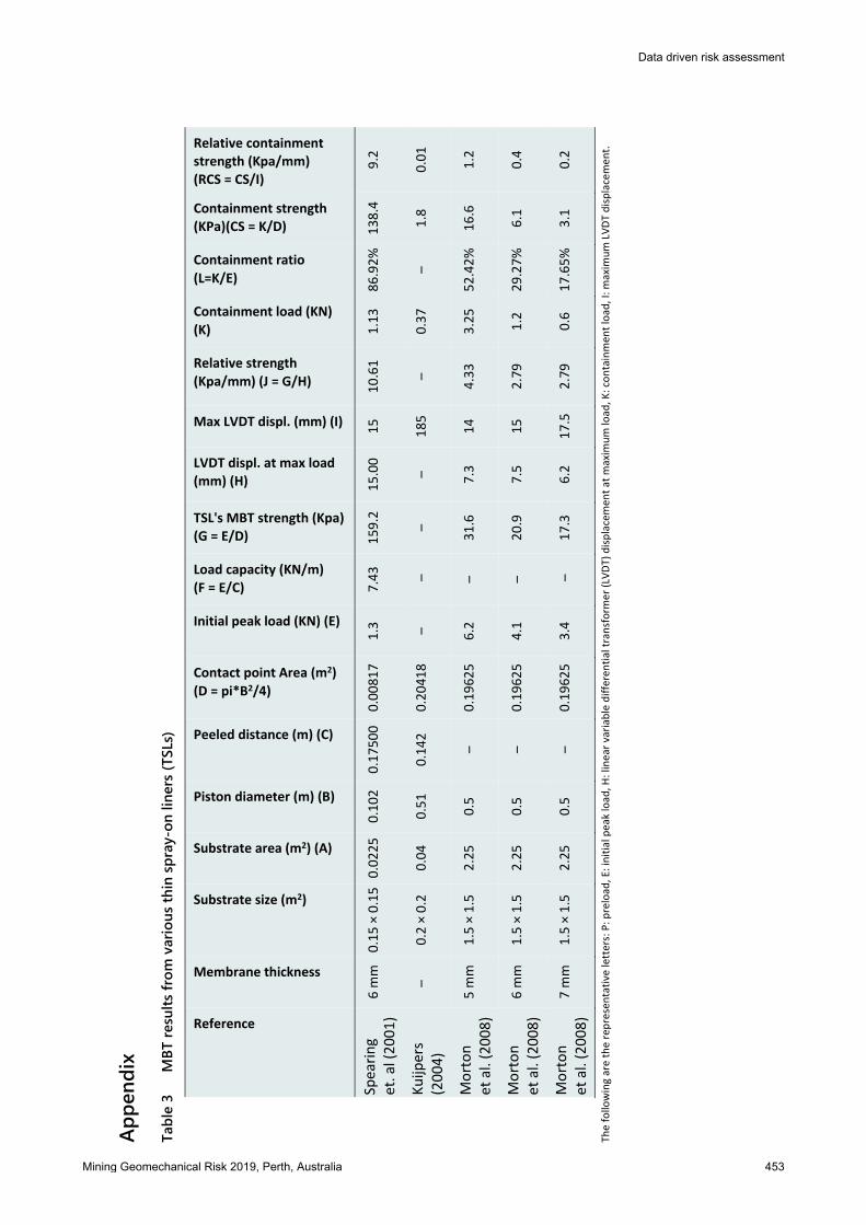
To find common ground for comparing MBT outcomes and the load capacity referred to by Spearing et al. (2001), two factors are introduced. These are the containment strength (CS) and the relative containment strength (RCS). A better understanding of these parameters can be achieved from some concepts explained through Figure 5 and the formulae displayed in Table 3 (see Appendix).

Review of the practical effectiveness of thin spray-on liners based on MJ Kanda and TR Stacey information from suppliers and observations from the mining industry
448 Mining Geomechanical Risk 2019, Perth, Australia
Figure 5 Membrane displacement test (MBT) load versus displacement graph model
The containment load is the TSL resisting force, kept almost constant until it is overcome by the mobilising forces, the CS is the containment load exercised over an area of contact between a plunger and the liner, and the RCS is the containment force of a membrane supposedly applied on the area of contact and capable of displacing the coating over a distance I. It is dependent on the liner’s elongation strength. Table 3 also presents the outcomes of some research on MBT method for TSLs. The aim is to demonstrate the impact of resorting to the CS and RCS, which can be easily determined and could constitute a common ground for comparison of TSL mechanical behaviours for MBT tests.
In Table 3, though Morton et al. (2008) tests show no containment forces, the lowest residual force is assessed as the permanent peeling force (referred to as the containment load) for the purpose of comparison. As observed, the initial peak peel strength, the containment ratio, the CS and the RCS vary considerably from one test to another, depending on whether the liners are fibre reinforced or not (Yilmaz 2011), and probably also on their ductility. This is the case of the tests by Spearing et al. (2001) which resulted in very high CS and RCS than the remaining results, which are believed to belong to less ductile TSLs. It is worth noting that the containment force is not always constant, with the load–displacement curve sometimes characterised by significant rebounds (Spearing et al. 2001). Also, the tests by Archibald (2004) were pull tests and not MBT experiments. However, these trials were assessing a combination of adhesion and intrinsic tensile strength as observed in the MBT trials and, as raised by this author, the initial peak pull (here assessed as peel) strength is a common and repeatable indicator. However, for the purpose of assessing the containment capability of the membranes, the CS should also be emphasised. The RCS should also be a powerful indicator but it is not clear whether some authors stopped the tests before a complete drop of force or due to a certain magnitude of crack extension. The nature of TSLs matters when deciding on the preparation mode, in the same way it influences the resulting strengths. It is preferable to always specify the TSL type.

Data driven risk assessment
Mining Geomechanical Risk 2019, Perth, Australia 449
3 Thin spray-on liner effectiveness based on information and observation from the mining industry
3.1 Practical membrane displacement test viewed by miners Some TSL attributes are crucial for its behaviour and should always be taken into account for assessment and design purposes (Tannant 2001). A few of these attributes are:
Timing of liner application: it is advisable to apply the spray‐on liner on the newly blasted heading, and even before the removal of the muck, to prevent loosening of the rock mass.
Continuous coverage versus web: instead of applying the liner on the overall surface, the liner’s consumption may be reduced by using intelligent equipment capable of spraying the liner only on the localised jointing zones, simulating a spider’s web (Tannant 2001).
Safety: contrary to meshing, liners can make use of robotic application and therefore, avoid the hazardous conditions involved in mesh support. The incidence of injuries due to rockfalls should thus be reduced. Robotic application would also avoid exposure to airborne isocyanate if an isocyanate base TSL is used.
Dirty or weak, crumbly rock: good adhesion is needed for a TSL to work satisfactorily, therefore the area should be well cleaned and small loose rocks removed before application.
Contamination of ore: it is not known yet if mining in a TSL‐supported zone will have a negative influence on milling and mineral recovery, as is observed with contamination of ore by shotcrete.
TSLs are gaining favour in the mining sector as a result of their capabilities for: face support, support between rock anchors, mesh replacement, support in areas prone to seismic instabilities, ground subject to weathering, spalling conditions, rock mass blasting damage, etc. (Guner & Ozturk 2016; Yilmaz 2011).
As described in the following sections, a practical assessment of TSL performance was undertaken in a deep and a shallow underground mine. The aim was to identify some of the causes of TSLs low performances. This shall finally lead to the provision of good practice guidelines for TSL application in underground mines.
3.2 Deep mine A South African Platinum mine was visited to assess its application of TSLs. This mine is currently deeper than 1,500 m below surface. It contains the platinum group metals located in the Bushveld Igneous Complex (BIC), which is the world's largest mafic‐ultramafic layered intrusion. The mine’s main reef has a high density, with its ore being very friable. Only the average rock mass rating (RMR) was availed, which is about 60. Unfortunately, in situ stress information was not available, but the mine is seismically active. No extended details will be provided, for the sake of confidentiality, but when needed, some other geotechnical details will be pointed out in the assessments of TSL performance presented in Table 4 (see Appendix).
3.3 Shallow mine The second mine visited is a South African shallow platinum mine, also in the BIC, with depth approximating 500 m, characterised by relatively dry conditions. The reef is similar to that of the deep mine. In situ stress measurements are not undertaken and the mine is not seismically active. Reasons for underperformance of TSLs are indicated in Table 5 (see Appendix). In addition to these collected data, and prior to some personal analyses, TSL users were directly interviewed and their opinions were also gathered.

Review of the practical effectiveness of thin spray-on liners based on MJ Kanda and TR Stacey information from suppliers and observations from the mining industry
450 Mining Geomechanical Risk 2019, Perth, Australia
3.4 Some opinions on thin spay-on liner performance based on interviews
3.4.1 Interview report with thin spay-on liner suppliers and users The summary of the interviews with the TSL users and the suppliers is presented in Table 6 (see Appendix).
From the information in this table, there is no single and isolated cause of underperforming TSLs that can be pointed out as a representative triggering factor for low performances. It is rather a combination of circumstances that can contribute to weaken the thin membranes support capabilities. The following section deals with opinions from a TSL supplier and a high level geotechnical inspector.
3.4.2 Interaction between a supplier and a geotechnical inspector regarding the performance of an applied thin spay-on liner
A case of interaction between a supplier and a rock engineer inspector regarding a performance of the Evermine TSL, a flexible liner, applied in an underground mine is presented in Table 2. The sector where this liner was applied is a drive wall and the assessment was made a few weeks after the curing period. The mine is located in a region characterised by the presence of hypersaline water. Though not being representative opinions, the discussion between these two technicians might lead to understanding of the diversified TSL performance and might also assist in decision‐making for employment of thin liners.
Table 2 Case of interaction between a supplier and a geotechnical inspector regarding an applied thin spray-on liners (TSL)
Technical opinions
Stability conditions prior to TSL application
Comments on TSL performance (and on the supplier’s view)
Way forward based on TSLs performance
TSLs supplier Not specified Excellent results from the work. The onsite geotechnical engineer was impressed and the product should be an alternative to shotcrete since it is very good ground support.
To expand the TSLs application over the mine. TSLs are very good supports indeed and easy to handle, and are likely to replace the shotcrete heavy logistic manoeuvres.
Geotechnical inspector
Stable since there are no unstable blocks
Disappointment with supplier’s interpretation of his product regarding the work because it is highly misleading and potentially dangerous to the mining sector. The product performed very poorly when hit by the underground loaders, thus it cannot be an alternative to shotcrete.
Based on the outcomes, this type of TSL should not be used in the mines. TSLs are believed to be very dangerous to the safety of underground workers and thus, though contrary to other organisations’ claims, geotechnical engineers should not advocate their use since some are difficult to spray, tear easily, toxic and expensive. They should favour shotcrete utilisation because TSLs cannot match it in energy absorption, toughness, and tensile and compression strengths. Neither can it be challenged by TSLs in terms of durability, time dependency and load transfer under static and dynamic conditions.

Data driven risk assessment
Mining Geomechanical Risk 2019, Perth, Australia 451
3.4.2.1 The supplier’s opinion on the applied thin spay-on liner
Apparently, this was by a simple observation, done just a short while after the curing time instead of looking at long‐term assessment. A better assessment should have been the application of these membranes in unstable areas or in appropriate areas where the supporting capabilities of TSLs should be triggered and thus its performance should have been accordingly assessed. This paper has taken this observation into account by assessing some TSLs applied in mine areas close to much disturbed sites (see some figures from Table 4 (see Appendix)). Various outcomes were issued depending on the nature and magnitude of the TSL’s underperforming factors.
3.4.2.2 The geotechnical inspector’s opinion on the applied thin spay-on liner
The feeling of disappointment following the interpretation made by the supplier and the onsite geotechnical engineer is justified based on the observations in the previous paragraph and the TSL, being a flexible liner, was expected to behave much better than it did. However, the categorical rejection of TSLs based on reasons such as poor performance when hit by underground loaders is very harsh. TSLs are not manufactured to resist mechanical impacts from underground equipment. The strong statement that no spray‐on liner could ever match shotcrete is yet to be validated for properties such as tensile strength, air tightness effect, and other factors such as toxicity, dynamic conditions, cost effectiveness, etc. Established and demonstrated arguments by organisations such as the Australian Centre for Geomechanics suggest some high performances of these thin liners in preference to shotcrete (Tannant 2001). Here as well, an in‐depth long‐term TSL performance study might help in assessing their real performance for stabilisation of rock mass infrastructure. It is important to underline the presence of hypersaline water, which might play a role in depreciating the TSL effectiveness, and this should be further investigated.
4 Conclusion TSL suppliers and users generally have divergent opinions regarding these membranes’ capabilities in the mining industry. Laboratory tests provide some TSL mechanical properties that are, in some cases, not reached in practice. This has resulted in scepticism over TSL utilisation as underground support. This research aimed to review TSL’s practical performance and to point out the reasons behind the divergence of opinions. Some TSL mechanical properties were reviewed, including the tensile strength, TSL’s strength enhancement effect on a shotcrete substrate and the representative membrane displacement testing method. In addition, some TSL performances were assessed by observation during mine visits and also from opinions of suppliers and geotechnical engineers. TSL underperformance may not be the result of a unique factor, but rather of a combination of negative triggering parameters. There are numerous types of TSLs with their own respective behaviours. This is likely to contribute to the uncertainty in the results obtained from thin liner utilisation. One should not assume that a TSL will show high performance because it performed well in other circumstances, however, specific tests simulating a maximum of in situ conditions such as temperature, humidity, rock mass conditions, in situ stress concentrations, etc. should be undertaken. In this particular research, it was proved from a coated BIT shotcrete test specimen, in conditions of relatively high temperature and humidity, that the geotechnical risk could have been underestimated if the test was performed in room temperature and humidity conditions. Humidity and temperature effects, as well as the effect of any in situ fluid or gas, should be incorporated in TSL laboratory tests.
Review of the practical effectiveness of thin spray-on liners based on MJ Kanda and TR Stacey information from suppliers and observations from the mining industry
452 Mining Geomechanical Risk 2019, Perth, Australia
5 Recommendations and guidelines for thin spray-on liner’s application in underground mines
Two main classes of TSLs are available; ductile (plastic) TSLs and brittle (mostly cement‐based) TSLs. Ductile TSLs behave differently from brittle TSLs. Within the same type of TSL, even from the same manufacturer, there might be a variation in proportions of constituents. Therefore, care should be taken when preparing a TSL by rigorously following the manufacturer’s suggested proportions, whether underground or in the laboratory.
Laboratory tested TSLs should always be representative of the assessed TSL quality. Therefore, the suppliers are advised to randomly withdraw laboratory samples from a relatively large population of TSL material bags. Quality control of their products should frequently be made to ensure the quality constancy of their products.
Careless mixing with excessive water or associated fluid should be avoided since it might lead to shrinkage distortion of the specimens while curing and thus, affect the laboratory test results or the in situ TSL performance.
The timing in preparing and applying TSLs is crucial, since a delay in applying the liner may affect its rheological properties and affect its ability to perform as expected.
TSL tensile and bond strength can increase the energy absorption capacity in the failure process, but since this hypothesis is not supported by some of the TSL users, as shown in this paper, the conditions in their mines should be simulated in the laboratory to settle the controversy.
Any mining decision to use membrane support should require prior evaluation of the stability conditions of the mine, and the characteristics of the potential thin liners should be fully known. These membranes should also be tested in conditions similar to the mine’s environment, with emphasis on temperature, humidity, and chemical composition of the flowing fluids and gas.
Liners that have fulfilled the prior requirements should be applied while components are still within their shelf life. They should be stored in dry and room temperature conditions, and not exposed to sunlight. The expected duration of their performance should also be assessed in relation to the current mine conditions.
As observed throughout this paper, the test results of support behaviour in the field are not generally the same as those obtained from laboratory tests. Therefore, the surface conditions of laboratory substrates and the underground rock mass should be similar, free of dust, cleaned down with water, and with approximatively the same atmospheric conditions. Substrate surfaces may optimally be prepared with a diamond saw.
TSLs should not be applied on weaker substrates such as shale, mudstone, etc. that may fail before the coating. In addition, it is recommended to avoid the utilisation of any substrate with cracks or structural failures.
The ability of a TSL type to support the rock mass depends on the load of the rock mass, the number of the mobilised blocks and the magnitude of their displacement within the rock mass. Thus, TSLs should not be applied on surfaces of rock masses that have excessive mobilised blocks.
The fact that TSLs are not structural supports has constituted a limitation in their adoption by users. An associated limitation in testing thin spray‐on membranes is the inability to maintain a uniform thickness when the liner is manually applied. Therefore, various thicknesses need to be assessed for the same set of tests and the respective ranges of results should always be provided. Alternatively, after a liner has been assessed, an equivalent test should be performed, but at a large scale, wherein the membrane could be sprayed with non‐uniform thickness. However, whenever feasible, robotic application should be preferred to maintain a uniform thickness
Appe
ndix
Tabl
e 3
MBT
resu
lts fr
om va
rious
thin
spra
y-on
liner
s (TS
Ls)
Reference
Membrane thickness
Substrate size (m2)
Substrate area (m2) (A)
Piston diameter (m) (B)
Peeled distance (m) (C)
Contact point Area (m2)
(D = pi*B2/4)
Initial peak load (KN) (E)
Load capacity (KN/m) (F = E/C)
TSL's MBT strength (Kpa) (G = E/D)
LVDT displ. at max load (mm) (H)
Max LVDT displ. (mm) (I)
Relative strength
(Kpa/mm) (J = G/H)
Containment load (KN)
(K)
Containment ratio
(L=K/E)
Containment strength (KPa)(CS = K/D)
Relative containment strength (Kpa/mm) (RCS = CS/I)
Spea
ring
et. al (2001)
6 m
m 0.15 × 0.15 0.0225
0.102
0.17500 0.00817
1.3
7.43
159.2
15.00
15
10.61
1.13
86.92% 138.4
9.2
Kuijp
ers
(2004)
–0.2 × 0.2
0.04
0.51
0.142
0.20418
– –
––
185
–0.37
–1.8
0.01
Morton
et al. (2008)
5 m
m
1.5 × 1.5
2.25
0.5
–0.19625
6.2
–31.6
7.3
14
4.33
3.25
52.42%
16.6
1.2
Morton
et al. (2008)
6 m
m
1.5 × 1.5
2.25
0.5
–0.19625
4.1
–20.9
7.5
15
2.79
1.2
29.27%
6.1
0.4
Morton
et al. (2008)
7 m
m
1.5 × 1.5
2.25
0.5
–0.19625
3.4
–17.3
6.2
17.5
2.79
0.6
17.65%
3.1
0.2
The follo
wing are the representative letters: P: p
reload
, E: initial p
eak load
, H: linea
r variab
le differential transform
er (LVDT) displacemen
t at m
axim
um lo
ad, K
: containmen
t load
, I: m
axim
um LVDT displacemen
t.
Data driven risk assessment
Mining Geomechanical Risk 2019, Perth, Australia 453

Tabl
e 4
Obse
rved
thin
spra
y-on
liner
(TSL
) beh
aviou
r in a
dee
p m
ine
Type of
excavation and
dep
th
Support unit and
estim
ated
thickn
ess
Reason for
TSL
application
Perform
ing
time
Comments
Illustrations
Crosscut
690 m
below
surface
Unkn
own TSL,
almost 6 m
m
thick
To prevent
the falls of
ground
4 years
Gen
erally, the observed
perform
ance was satisfactory. H
owever, a number of sites were
iden
tified
which showed
signs of TSL failu
re, p
robab
ly due to m
obilised blocks of rocks.
Crosscut
750 m
below
surface
TSL A, 5
mm thick
To prevent
the scalin
g of the rock
mass
11 years
The TSL is lo
calised
nea
r the footw
all and has experien
ced a lo
ss of ad
hesion. The failu
re is
sign
ifican
t, alm
ost covering an
area of 1 × 0.2m. The surface where the lin
er has bee
n
applied is smooth; h
umidity an
d dust m
ight be the cau
ses of the loss of ad
hesion.
Neigh
bourhood of
an aban
doned
mining zone.
750 m
below
surface
Combination of
TSL, wire m
esh,
anchors and rope
lacing
Poor area
conditions
11 years
Approaching an
aban
doned
section of the mine, the type of support has chan
ged. H
owever,
the combined
support system see
ms to have contributed to stabilising the hazardous rock
mass zone. The supports might have bee
n applied ju
st before the significan
t mobilisation of
rock blocks.
Close to an
aban
doned
pan
el.
750 m
below
surface
Idem
Poor area
conditions
11 years
Through
a combination of wire m
esh, anchors, rope lacing an
d TSLs have been
employed,
failu
re of the rock m
ass could not be prevented and apparen
tly the elongation cap
acity of
the TSL was exceeded, b
ut the wire m
esh could still retain the rock m
ass which is
interpreted as a basket mechan
ism. H
owever, the number of mobilised blocks of rock m
ass
might have been excessive at the time of TSL ap
plication. N
evertheless, the combination
with wire mesh should be compulsory in
such aban
doned
areas which are nea
r the zones of
activity.
Han
ging wall at
842 m
below the
surface
Unkn
own TSL
Secondary
support
Unkn
own
There is lo
ss of ad
hesion. The failu
re m
ight be due to unkn
own cau
ses since the surface
looks adeq
uate for go
od adhesion, and there is no sign of a geotechnical disturbing zone. It
is worth noting that the detached
area of lin
er only rep
resents a very sm
all p
ortion of ab
out
25 × 15 cm
2 and m
ight have bee
n forced
out for an
unkn
own rea
son.
Review of the practical effectiveness of thin spray-on liners based on information from suppliers and observations from the mining industry
MJ Kanda and TR Stacey
454 Mining Geomechanical Risk 2019, Perth, Australia

Tabl
e 5
Obse
rved
thin
spra
y-on
liner
(TSL
) beh
aviou
r in a
shall
ow un
derg
roun
d m
ine
Type of excavation,
depth below surface
and RMR values
Support unit and
estim
ated
thickn
ess
Reason for TSL’s
application
Perform
ing
time
Commen
ts
Illustrations
Drive at 80 m
, RMR: >
65
Mix of unknown
TSL (4–5
mm) an
d
shotcrete with
variab
le thickn
ess
High excavation –
to negate the
nee
d for barring
37 m
onths
Patches of exposed rock surface iden
tified
but not
due to deterioration, m
ost likely m
echan
ical
dam
age, support in
stalled in addition to primary
support of 1.6 m
resin bolts an
d secondary support
of 3.5 m
cab
le anchors.
Belt drive at 330 m
below surface,
RMR: 6
5–7
7
TSL A and TSL D
(about 5–7
mm
thick), resin bolts
and cab
le anchors
High excavation –
to negate the
nee
d for barring
25 m
onths
Portions iden
tified
where the TSL thickn
ess was
substan
dard ‐ estim
ated
at less than
4 m
m,
support in
stalled in
addition to primary support of
1.6 m
resin bolts an
d secondary support of 3.5 m
cable anchors.
Belt drive at 350 m
below surface,
RMR: 5
7
TSL A (5–7
mm)
and rope lacing
Pillars scaling
10 m
onths
No issues after applying TSL.
Bord at 204 m
below
surface, RMR: 5
7
TSL D (5–6
mm)
and friction bolts
Poor ground
conditions an
d
undersized pillars
with Factor of
Safety <1.25
5 m
onths
Han
ging wall w
ith no historical geo
technical issues
but some TSL ad
hesion failures were observed
Data driven risk assessment
Mining Geomechanical Risk 2019, Perth, Australia 455

Tabl
e 6
Sum
mar
y of i
nter
views
with
thin
spra
y-on
liner
(TSL
) sup
plier
s and
user
s To
pic
Opinions from a deep m
ine
Opinion from a shallow m
ine
Opinions from TSL’s supplie
r 1
Opinions from TSL’s supplie
r 2
Average age of ap
plied TSL
11 years
6 years
17 years
11 years
Types on rock where TSL is
applied
Igneo
us an
d m
etam
orphic (RMR: 60 in
average)
Igneo
us (RMR: 5
2‐77, b
ut some
scaled pillars had
a RMR of 43)
Igneo
us, m
etam
orphic and
sedim
entary
Igneo
us an
d M
etam
orphic
Type of TSL
Polymer cem
ent
Polymer cem
ent
Polymer cement
Polymer cement an
d Polymer only
TSL’s thickn
ess
>4 m
m
>4 m
m
>4 m
m
>4 m
m
Freq
uen
tly combined
support
with TSL
Friction rockbolts of 2.4 m
(primary) and
wire mesh added
to compen
sate the de‐
bonded
TSLs
Rockbolts (18 m
m, 1
.6 m
resin bolts
to bea
r 14 t cap
acity)
Rockbolts an
d wire mesh (this is
suitab
le for dynam
ic stresses)
Rockbolts an
d wire mesh
Infrastructures where TSLs
better perform
ed
None
Unkn
own
Tunnels, stopes, h
igh stress an
d
stress chan
ging area
s Tu
nnels, ore passes
Observed
failure properties
Adhesive failure
Tensile failure, A
dhesive failure
Adhesive failure due to application in
excessive water dripping an
d
dam
pness in wall
Adhesive failure, shear bond failure
Freq
uen
t load
ing mechan
ism
Water pressure load
ing
Slab
mechan
ism
Unkn
own
Unkn
own
Moisture conditions
Humid
Dry
Variable: D
ry, h
umid or very wet
Variable: d
ry, h
umid or very wet
Underperform
ing moisture
conditions zones
Humid
Dry
Very wet
Dry, if not prepared
/clean
ed prior
to TSL’s application
Surface preparation prior to
TSL’s ap
plication
Yes
Unkn
own
Yes
Not sure
Temperature condition
Unkn
own
Unkn
own
30–4
0°C
Variable
Geo
logical structures triggering
TSL’s failu
re
Joints
Scaling pillar
Unkn
own
Norm
al
TSL’s time of effectiven
ess
Unkn
own (even
fail just less than
an hour
after the recommen
ded
curing time)
Unkn
own
10–2
0 years
Not sure
Major principal stress
<70 M
Pa
Less than
70 M
Pa
100–1
40 M
Pa
Not sure
Most common difficulties
during TSL’s ap
plication
TSL sprayed on easily but failed when
drilling support through
it and then
after
blasting
Homogeneity of the mixture
Quick setting time of the products,
lead
ing to blockage
–
Review of the practical effectiveness of thin spray-on liners based on information from suppliers and observations from the mining industry
MJ Kanda and TR Stacey
456 Mining Geomechanical Risk 2019, Perth, Australia
Data driven risk assessment
Mining Geomechanical Risk 2019, Perth, Australia 457
References Archibald, J 2004, ‘Canadian laboratory and field testing’, in Y Potvin, TR Stacey & J Hadjigeorgiou (eds), Surface Support in Mining,
Australian Centre for Geomechanics, Perth, pp. 73–87. Archibald, JF & DeGagné, DO 2000, ‘Recent Canadian Advances in the application of spray‐on polymeric linings’, Mining Health and
Safety Conference, Sudbury. ASTM 2010, Standard Test Method for Tensile Properties of Plastics, American Society for Testing Materials Committee D‐20 on
Plastics. Guner, D & Ozturk, H 2017, ‘Tensile‐creep test specimen preparation practices of surface support liners’, IOP Conference Series: Earth
and Environmental Science, vol. 95, p. 042004. Guner, D & Ozturk, H 2016, ‘Experimental and numerical analysis of the effects of curing time on tensile mechanical properties of
thin spray‐on liners’, Rock Mechanics and Rock Engineering, vol. 49, issue 8, pp. 1–18. Kanda, M & Stacey, T 2016, ‘The influence of various factors on the results of stability analysis of rock slopes and on the evaluation
of risk’, Journal of the Southern African Institute of Mining and Metallurgy, vol. 116, issue 11, pp. 1075–1081. Kuijpers, JS 2004, ‘Evaluation of thin spray‐on liners support behaviour’, in Y Potvin, TR Stacey & J Hadjigeorgiou (eds), Surface Support
in Mining, Australian Centre for Geomechanics, Perth, pp. 103–112. Lacerda, L & Rispin, M 2002, ‘Current ground support membrane applications in North American underground mines’, Proceedings
of the 2nd International Seminar on Surface Support Lines: Thin Sprayed Liners, Shotcrete and Mesh, South African Institute of Mining and Metallurgy, Johannesburg.
Morton, EC, Thompson, AG & Villaescusa, E 2008, ‘Static testing of shotcrete and membranes for mining applications’, in TR Stacey & DF Malan (eds), Proceedings of the 6th International Symposium on Ground Support in Mining and Civil Engineering Construction, SANIRE, SAIMM and ISRM, Cape Town, pp. 195–212.
Mpunzi, P, Masethe, R, Rizwan, M & Stacey, T 2015, ‘Enhancement of the tensile strengths of rock and shotcrete by thin spray‐on liners’, Tunnelling and Underground Space Technology, vol. 49, pp. 369–375.
Pappas, DM, Barton, TM & Weiss, ES 2004, ‘The long‐term performance of surface support liners for ground control in a underground limestone mine’, in Y Potvin, TR Stacey, & J Hadjigeorgiou (eds), Surface Support in Mining, Australian Centre for Geomechanics, Perth, pp. 157–166.
Potvin, Y, Stacey, TR & Hadjigeorgiou, J 2004, Surface Support in Mining, Australian Centre for Geomechanics, Perth. Spearing, A, Ohler, J & Attiogbe, E 2001, ‘The effective testing of thin support membranes (superskins) for use in underground mines’,
An International Seminar and Field Trials on Surface Support Liners: Membrane, Shotcrete and Mesh, Australian Centre for Geomechanics, Perth, Section 26.
Stacey, TR 2001, ‘Review of membrane support mechanisms, loading mechanisms, desired membrane performance, and appropriate test methods’, The Journal of The South African Institute of Mining and Metallurgy, vol. 101, issue 7, pp. 343–352.
Stacey, TR & Kasangula, K 2004, ‘Results from testing of TSLs using a simple, low cost laboratory test’, in Y Potvin, TR Stacey & J Hadjigeorgiou (eds), Surface Support in Mining, Australian Centre for Geomechanics, Perth, pp. 147‐150.
Tannant, D 2001, ‘Thin spray‐on liners for underground rock support testing and design issues’, An International Seminar and Field Trials on Surface Support Liners: Membrane, Shotcrete and Mesh, Australian Centre for Geomechanics, Perth, Section 27.
Tannant, D, Swan, G, Espley, S & Graham, C 1999, ‘Laboratory test procedures for validating the use of thin spray‐on liners for mesh replacement’, Proceedings of the 101st Annual General Meeting, Canadian Institute of Mining, Metallurgy and Petroleum, Westmount.
Yilmaz, H 2010, ‘Tensile strength testing of thin spray‐on liner products (TSLs) and shotcrete’, The Journal of The South African Institute of Mining and Metallurgy, vol. 110, issue 10, pp. 559–569.
Yilmaz, H 2011, Development of Testing Methods for Comparative Assessment of Thin Spray‐on Liner (TSL) Shear and Tensile Properties, PhD thesis, University of the Witwatersrand, Johannesburg.
Yilmaz, H 2014, ‘Comparison of tensile strength of shotcrete and thin spray‐on liners (TSLs)’, Proceedings of the 8th Asian Rock Mechanics Symposium, International Society for Rock Mechanics and Rock Engineering, Lisbon, pp. 177–182.
Review of the practical effectiveness of thin spray-on liners based on MJ Kanda and TR Stacey information from suppliers and observations from the mining industry
458 Mining Geomechanical Risk 2019, Perth, Australia