review reverse engineering a protein: the mechanochemistry of atp
TRANSCRIPT

Review
Reverse engineering a protein: the mechanochemistry of ATP synthase
George Oster *, Hongyun WangDepartment of Molecular and Cellular Biology and College of Natural Resources, University of California, Berkeley, CA 94720-3112, USA
Received 19 April 1999; received in revised form 26 July 1999; accepted 5 August 1999
Abstract
ATP synthase comprises two rotary motors in one. The F1 motor can generate a mechanical torque using the hydrolysisenergy of ATP. The Fo motor generates a rotary torque in the opposite direction, but it employs a transmembrane protonmotive force. Each motor can be reversed: The Fo motor can drive the F1 motor in reverse to synthesize ATP, and the F1
motor can drive the Fo motor in reverse to pump protons. Thus ATP synthase exhibits two of the major energy transductionpathways employed by the cell to convert chemical energy into mechanical force. Here we show how a physical analysis of theF1 and Fo motors can provide a unified view of the mechanochemical principles underlying these energytransducers. ß 2000 Elsevier Science B.V. All rights reserved.
Keywords: ATP synthase; Bioenergetics ; Mechanochemistry; Modeling; ATP Hydrolysis
1. Introduction
ATP synthase is unique amongst proteins in that itembodies two of the major cellular energy transduc-tion mechanisms. F1 can synthesize ATP, but it canalso hydrolyze ATP to operate as a motor. Fo canconvert a transmembrane ion gradient into a rotarytorque, or it can be driven in reverse to perform asan ion pump. As the content of this volume attests,we now know a great deal about the structure, bio-chemistry, genetics, and energetics of ATP synthase.An important missing piece in the story of this ex-traordinary protein is an understanding of the basicphysical principles that underlie its operation.
This growing body of knowledge has stimulatedseveral workers in the ¢eld to o¡er qualitative sce-narios for the mechanisms of both F1 and Fo. How-ever, there is no way to know which, if any, of thesescenarios are consistent with the laws of chemistryand physics, nor to make quantitative predictions tocompare with experiments. Therefore, we set abouttrying to construct a quantitative model for both F1
and Fo that would encapsulate the current state ofexperimental knowledge and provide insight into thefundamental mechanisms by which ATP synthaseoperates.
The models are formulated as equations that aresolved on a computer. A detailed account of thesecalculations can be found in the supplemental mate-rial to the published papers [1^3]; calculations notgiven in these references are included here as appen-dices. In this review we endeavor to present an in-tuitive account of how the models were constructedand clearly delineate our assumptions and why wemade them. Of course, di¡erent assumptions are
0005-2728 / 00 / $ ^ see front matter ß 2000 Elsevier Science B.V. All rights reserved.PII: S 0 0 0 5 - 2 7 2 8 ( 0 0 ) 0 0 0 9 6 - 7
* Corresponding author. Fax: +1-510-642-7428;E-mail : [email protected]
BBABIO 44855 24-5-00 Cyaan Magenta Geel Zwart
Biochimica et Biophysica Acta 1458 (2000) 482^510www.elsevier.com/locate/bba

possible, and so the models were constructed so asto handle alternate hypotheses, such as di¡erent ki-netics or structures. In this way the models can serveas vehicles for testing various hypotheses againstnew experimental information as it becomes avail-able.
In this review we will also introduce an importantnew aspect to the F1 model which is a consequenceof its high mechanical e¤ciency. We will show thatthe mechanical and kinetic data require that thepower stroke that drives rotation must derive its en-ergy from the binding of ATP to the catalytic sites.Further, this binding transition must take place grad-ually from weak to tight. We call this process the`Binding Zipper'. The energy from hydrolysis of theQ-phosphate bond is used to weaken the tight bindingso the products can be released and the cycle canrepeat. We will see that a mechanochemical cyclebuilt around the Binding Zipper uni¢es many ofthe experimental ¢ndings on the F1 motor.
Fig. 1 shows the overall geometry of ATP syn-thase. The F1 motor/synthesizer consists of subunitsK3L3QO. The Fo motor/pump consists of subunitsc12ab2N. A more functional breakdown of the sub-units arises from the realization by Boyer, and theunequivocal demonstration by the laboratories ofYoshida and Kinosita, that F1 is a rotary machine[4^7]. The rotational motion of the Fo motor hadbeen inferred from the cylindrical organization ofthe c12 subunit, and the fact that it is connected toF1 by the QO shaft. However, recent experiments havedirectly con¢rmed that the c12 subunit rotates withthe Q shaft (M. Yoshida, personal communication).Thus the convention has arisen to refer to the coun-ter-rotating subunit collections QOc12 and ab2NK3L3 asthe `rotor' and `stator', respectively. Because both F1
and Fo are rotary motors, we can analyze theirmechanochemical coupling more easily than otherprotein motors whose motions are more compli-cated.
2. The F1 motor
The experiments of Yoshida's and Kinosita's lab-oratories provided a striking visual con¢rmation ofthe rotary motion of the F1 motor [7]. Equally asimportant from the viewpoint of modeling, they es-
tablished the following characteristics of the F1 mo-tor [6] :
b The motor rotated in three steps per revolution;rotation was stochastic, with occasional backwardsteps.
b Each step corresponded to the hydrolysis of oneATP.
b At high ATP concentration, the viscous dissipationper revolution as computed from the mean velocitywas about the same as the free energy of hydro-lyzing three ATPs. This means that, at these con-ditions, the energy conversion e¤ciency from nucle-otide hydrolysis to rotary torque is close to 100%.Consequently, there must be very tight couplingbetween the mechanics and the chemistry so thatentropic losses are small. This high e¤ciency alsoimplies that the rotary torque generated is nearlyconstant. Because this amazing result informsnearly every step in constructing the model, it mer-its a more detailed explanation, which we give inAppendix A.
In constructing the model we proceed sequentiallyas follows. First, we must establish the geometricalmotions the F1 subunits undergo (`kinematics'). Thenwe introduce the mechanical forces that drive theconformational changes (`dynamics'). Next, we mod-el the chemical reactions that provide the energy thatgenerates the forces. Finally we show how the chem-istry and mechanics are coordinated so as to achievethe high energy conversion e¤ciency observed in theexperiments.
The form of the equations that constitute the mod-el are very simple. Let a(t) denote the angular posi-tion of the Q subunit at time t, and let s(t) denote the`chemical state' of F1 at the same instant. By this wemean the occupancy of the three catalytic sites(Empty, ATP, ADP�Pi, ADP). Then the mechanicalbalance of torques on the Q shaft is :
�1�
Here j is a viscous drag coe¤cient, dB(t) is the torquedue to Brownian motion, and the three torques,dLH(a,s), are developed at the F1 catalytic sites duringthe nucleotide hydrolysis cycle. This mechanical
BBABIO 44855 24-5-00 Cyaan Magenta Geel Zwart
G. Oster, H. Wang / Biochimica et Biophysica Acta 1458 (2000) 482^510 483

equation must be coupled to the evolution of thechemical state, s, which we can write symbolicallyas
dsdt� K�a�Ws �2�
where K(a) is a matrix of all of the rate constants,each of which depends on the angular position of theQ shaft. Our task is to £esh out the speci¢cs of Eqs. 1and 2. To do this we must construct a model for howthe torque, dH(a,s) is generated by the hydrolysiscycle, and how the reaction rates, K(a), are coordi-
nated with the rotation so as to achieve the observedrotation rates and mechanical e¤ciency. We begin byexamining the conformational motions of F1 duringthe hydrolysis cycle in detail.
2.1. Kinematics: the molecular motions thataccompany rotation
The structures elucidated by Walker's laboratoryrevealed the conformational changes in F1 that ac-companied rotation [8]. They were able to capturethe conformations corresponding to three states in
Fig. 1. The geometry of ATP synthase. The soluable F1 portion lies below the level of the membrane; Fo is the transmembrane sec-tor. The `rotor' consists of subunits QOc12, and the `stator' of subunits ab2NK3L3. The F1 motor experiments were carried out with onlyK3L3Q. (Reprinted from Structure, 1999 with kind permission from Elsevier Science Ltd.)
BBABIO 44855 24-5-00 Cyaan Magenta Geel Zwart
G. Oster, H. Wang / Biochimica et Biophysica Acta 1458 (2000) 482^510484

the hydrolysis cycle. We combined the Protein DataBank (PDB) structures with Boyer's binding changemechanism [9] to construct a movie of the conforma-tional cycle of F1.1 To do this we assumed that thetransition between adjacent states shown in the PDBstructure corresponded to one third of a rotation bythe Q shaft. We then devised a cylindrical interpola-tion scheme to estimate the conformational sequencethrough an entire rotation. This gave us the kine-matic sequence shown in Fig. 2, from which we de-duced the following facts:
b The major conformational change of the L sub-units is a rotation of the upper portion of L inFig. 2 about 30³ with respect to the lower portion.This comes about because of a combination ofrotation and shear between helices B and C [10]abutting the catalytic site. We modeled the bend-ing of the L subunits by a relative rotation of theupper and lower portions at an equivalent `hinge'point located such that it achieves the same motionas the rotation and shear motions in the actualbending motion of L.
b The K subunits alter their conformation onlyslightly, and passively in response to the L mo-tions.
b The rotation of the eccentric Q shaft is driven bythe successive bending of the three L subunits. Thisbending pushes the region on L near LIle390 andLLeu391 against Q at the level near QMet25 andQAla235, much like turning the crankshaft on anautomobile (Fig. 3).
b The direction of rotation is determined by the rel-ative angular position of the `most eccentric point'near QMet25 shown in Figs. 2 and 3 with respect toGate 1 near QGln255 which we will discuss below.
2.2. Dynamics: the forces that drive rotation
Having established that the bending of the L sub-units turns the Q shaft by pushing on its o¡-axiseccentric portion, we must next determine how thecatalytic site generates the forces that drive thisbending. In this we are seriously constrained by the
F1 motor's ability to convert nearly 100% of the freeenergy derived from the hydrolysis cycle into rotarymotion. In Appendix A we show that the torque gen-erated at the catalytic site must be nearly constant,which precludes a `Brownian ratchet' mechanism[1,11,12].
A second constraint arises from the free energychanges during the hydrolysis cycle computed frommeasurements of the unisite reaction rates (i.e. whennucleotide concentrations are so low that, on aver-age, only one catalytic site is occupied). The overallreactions during the hydrolysis cycle at a catalyticsite can be written:2
�3�
The unisite free energy diagram in Fig. 4b shows thattwo major free energy drops take place during thiscycle. The ¢rst takes place when ATP binds the cat-alytic site and the second when phosphate is releasedafter hydrolysis [13,14]. This suggests that the F1
motor executes two power strokes during each hydro-lysis cycle. We denote these as the primary powerstroke (PS1) and the secondary power stroke(PS2) ; PS1 is somewhat larger than PS2. Here wepresent one mechanism of energy conversion that ¢tsthese requirements, and that will enable the model toreproduce all of the experimental observations.
In the original formulation of the F1 motor [2], weassumed that the binding of nucleotide to the cata-lytic site is converted into elastic strain energy withinthe L subunit. That is, about 24 kBT is conferred onthe protein when ATP binds to the catalytic sites.This phenomenological assumption was su¤cient toreproduce the experimental data. Here we present amore detailed scheme which justi¢es the phenomeno-logical model, and delves somewhat deeper into theevents taking place at the catalytic site.
ATP binding involves the formation of hydrogenbonds as the nucleotide thermally settles into thecatalytic site, as shown schematically in Fig. 4a.One way to generate a constant force is if the bindingprocess proceeds as a sequential annealing of hydro-gen bonds, represented by the staircase energy func-tion Fig. 4b. We will call this process the `Binding
1 Movies of the kinematic motions can be downloaded from:http://nature.berkeley.edu/uhongwang/ATP-synthase 2 ATP always refers to Mg��WATP.
BBABIO 44855 24-5-00 Cyaan Magenta Geel Zwart
G. Oster, H. Wang / Biochimica et Biophysica Acta 1458 (2000) 482^510 485

BBABIO 44855 24-5-00 Cyaan Magenta Geel Zwart
G. Oster, H. Wang / Biochimica et Biophysica Acta 1458 (2000) 482^510486

Zipper' ; Appendix B discusses this notion in moredetail. There we show that this mechanism has therequired high energy conversion e¤ciency, and thatit generates a force that is approximately constantwith displacement (similar to surface tension or apre-stretched spring), as compared to a force thatincreases with displacement characteristic of an elas-tic spring. Moreover, when the cycle is reversed dur-ing ATP synthesis, the Binding Zipper mechanismprovides an e¤cient mechanism to `unzip', that is,gradually reduce the binding a¤nity of ATP andrelease it with a minimum of dissipation. Thus weenlarge the reaction sequence in Eq. 3 to the follow-ing kinetic scheme:
ASSUMPTION: The Binding Zipper
�4�
Here the large dot is intended to distinguish the tightbinding state at the end of the Binding Zipper fromthe weak binding state when ATP ¢rst enters thecatalytic site. Eq. 4 decomposes the binding step inEq. 3 into ATP docking followed by a sequence ofsubsteps corresponding to the zipping of bonds be-tween ATP and the catalytic site. Because of the tightmechanical escapement, as the binding transition ad-
vances, the L subunit bends, and the Q subunit ro-tates. In the model we shall separate the kinetic tran-sitions in equation into two categories: (i) kinetictransitions associated with changes in the occupancyof the catalytic site, and (ii) kinetic transitions asso-ciated with rotation of the Q shaft. The kinetic states,s, in Eqs. 2 and 3 describe only the occupancy of thecatalytic site. The rotation of Q is described by Eq. 1.
In order to release the hydrolysis energy in twosteps we make the following
ASSUMPTION: The open con¢guration is the rest po-sition of L when it is empty. As the binding free energyof ATP generates a constant force to bend L (the Bind-
Fig. 3. Schematic of the mechanical escapement. Here we ab-stract the structure in Fig. 2 as a cartoon frame. The Q shaft isheld by K3L3 at the middle and the bottom levels. At the toplevel (the driving level), the Q shaft is o¡-center. As the Lsbend, they generate a rotary torque by pushing o¡-axis on theQ shaft at the driving level. When projected onto the drivinglevel and viewed from the top, the `most eccentric point'(MEP) leads Gate 1 in the counter-clockwise direction. Thuswhen the interaction of Gate 1 with L admits ATP to the cata-lytic site and starts the bending motion of a L, the MEP haspassed that L. Thus the bending motion of L drives the Q shaftto rotate in the counter-clockwise direction.
Fig. 2. Conformational changes accompanying the rotation ofthe Q shaft. The top panel shows the ribbon structure of a Land Q subunit [8]. The top portion of L (red) contains helix Band the bottom portion contains helix C, both of which abutthe catalytic site. On the Q coiled coil the `most eccentric point'(MEP, green) is located furthest from the axis of rotation. Gate1 and Gate 2 (red) are located diametrically opposite one an-other. The bottom four panels show four frames from the inter-calation movie. The Q shaft has three contact levels with theK3L3 hexamer. The Q shaft is held at two lower levels (circles atthe middle and the bottom) by the K3L3 hexamer. The top por-tion of L impinges on Q at the level near the MEP (the circle atthe top). The stop frames at a= 0, Z/4, Z/2, and Z show thatthe `bearing' level regions (the middle and bottom circles) re-main coaxial, while the driving level contact (top circle) rotateso¡-center in concert with the bending of the Ls.6
BBABIO 44855 24-5-00 Cyaan Magenta Geel Zwart
G. Oster, H. Wang / Biochimica et Biophysica Acta 1458 (2000) 482^510 487

Fig. 4. Modeling the power stroke. (a) The Binding Zipper: ATP binds to the catalytic site by a rapid thermal `zippering' of hydrogenbonds. The closing of the site around the nucleotide creates an approximately constant torque about the hinge point in L, causing theupper portion of L to rotate with respect to the lower portion. At the end of the power stroke ATP is tightly bound. The energy inthe Q phosphate bond is used to break the tight binding so that phosphate and ADP can be released. (b) Free energy diagram for thehydrolysis cycle: The free energy levels are calculated from the reaction rates measured at unisite reaction conditions [13]. In the cal-culation, we used [ATP] = 1 mM; [ADP] = 0.01 mM and [Pi] = 0.1 mM. The two major free energy drops occur at nucleotide bindingand upon phosphate release. The second drop re£ects release of elastic strain energy stored in L during nucleotide binding. There aretwo power strokes: the primary power stroke (PS1) is driven by the Binding Zipper, and the secondary powerstroke (PS2) is drivenby the elastic recoil of the passive spring. The magnitudes of the free energy drops are accurate, but the sizes of the energy barriersare not to scale. Note that the `states' F1WATP and F1WADP correspond to a range of free energies since the chemistry is coupled tothe bending of the L subunits. `Gate 1' controls the admission of ATP to the catalytic site and `Gate 2' controls the release of phos-phate (see Fig. 7).
BBABIO 44855 24-5-00 Cyaan Magenta Geel Zwart
G. Oster, H. Wang / Biochimica et Biophysica Acta 1458 (2000) 482^510488

ing Zipper), a portion of the force is used to storeenergy in L as elastic strain.
This means that the free energy induced by ATPbinding acts in two ways: (i) directly to bend L andturn the Q shaft (PS1), and (ii) to store elastic energyin the L subunit as it bends against its elastic resis-tance. The second power stroke (PS2) is driven bythe recoil of this stored elastic energy. To model this,we treat the L subunit as an elastic body, as shownschematically in Fig. 5a. The free energy associatedwith assembly of the protein generates a `resting statestrain' when the catalytic site is unoccupied.3 Thepassive elasticity of the L subunit is represented bya spring at the hinge axis. The constant force gener-ated by the ATP Binding Zipper is represented sym-bolically by an active element that is introduced atthe moment of ATP docking. Fig. 5b shows the en-ergy changes within the protein, in contrast to theexternally measured free energy changes in Fig. 4b.
As ATP settles into the catalytic site, the bindingfree energy drives the primary power stroke (PS1)that turns Q by about a third of a revolution. Atthe same time, it compresses the passive spring, stor-ing elastic energy. When phosphate is released, thisstored elastic energy drives the secondary powerstroke (PS2) as it recoils from its strained state.This recoil power stroke assists the next L subunitin the hydrolysis sequence as it executes its primarypower stroke. We will see later how these two powerstrokes are coordinated with the hydrolysis reactions.Releasing the energy resulting from ATP binding intwo steps helps making the output torque uniformand increases the mechanical stability of the F1 mo-tor because the drive force on the Q shaft comes fromtwo of the three Ls at any moment. Therefore, during
Fig. 5. Modeling the forces. (a) The mechanical model. The Lsubunit is divided into an upper and lower portion that can ro-tate about a hinge point. The elasticity of the protein is repre-sented by the coiled spring at the hinge. Upon ATP docking atthe catalytic site, a constant force generator (the Binding Zip-per) is introduced that tends to close the angle between the twoportions. We measure the bending of the L subunit by the angleP, which is sterically constrained to lie between Pmin and Pmax.From the kinematic study Pmax3PminW30³. (b) Internal energyof the L subunit. The internal energy includes both the internalenergy of the protein and the energy of interaction between thenucleotide and the catalytic site. The enthalpic part of the as-sembly free energy results in K3L3 with a resting elastic energyat R. Immediately upon entering the catalytic site ATP initiatesthe Binding Zipper and shifts the internal energy upwards tostate S (dashed line) by an amount equal to the enthalpic partof the binding free energy. The binding transition from weak totight generates the primary power stroke (PS1) from S to T,which closes the angle P between the upper and lower portionsof L. This binding transition also stores elastic energy in theprotein when L is bent against its elasticity. Upon release ofphosphate, the overcompression of the passive spring drives thesecondary power stroke (PS2) by elastic recoil from T to R.
C
3 The structure of nucleotide free KL suggests that the open(unbent) con¢guration is a stable rest state for an empty L [18].That is, this stable con¢guration is a constrained elastic energyminimum created during assembly by the free energy of associa-tion. If so, then when L bends, additional elastic strain energy isstored in the protein.
BBABIO 44855 24-5-00 Cyaan Magenta Geel Zwart
G. Oster, H. Wang / Biochimica et Biophysica Acta 1458 (2000) 482^510 489

the rotation, the stress is more uniformly distributedon the K3L3 barrel.
Both power strokes, PS1 (the Binding Zipper) andPS2 (the elastic recoil), can be expressed in terms ofa potential function that depends on the bendingangle, P, of the L subunit. However, equation gov-erning the rotation of the Q shaft is in terms of therotation angle a. Because of the high energy conver-sion e¤ciency the mechanical coupling between the
Fig. 6. The elastic potentials associated with the F1 motor. (a)The potentials that drive the F1 motor. The interaction betweenthe Q shaft and each catalytic site is described by a set of fourpotentials which vary as functions of a. Each potential curverepresents the free energy of one L subunit and the nucleotides insolution. The potentials shown here are for the concentrations:[ATP] = 1 mM; [ADP] = 1 WM; [Pi] = 1 WM. This set of unphys-iological concentrations is selected to make the four potentialswell separated from each other. The vertical distance betweenthe two Empty curves shown corresponds to the free energychange of the system after one hydrolysis cycle. The total inter-action between the Q shaft and the three Ls is described bythree sets of these potentials o¡set by 2Z/3. Here we visualizethe total interaction by placing three legs, rigidly connected ando¡set by 2Z/3, on one set of potentials, so that each leg is onthe potential curve corresponding to the reaction state of a L.The interaction between the potentials and the leg marked Li
represents the interaction between Li and the Q shaft. A typicalsequence for L1 is shown beginning on the top Empty statecurve and ending on an Empty state curve vGATP lower aftercompletion of one hydrolysis cycle. (1) Gate 1 admits ATP tothe catalytic site of L1. (2) the primary power stroke of L1
drives Q, assisted by the secondary (recoil) power stroke of L3.(3) Gate 2 triggers the release of phosphate on L1. (4) The sec-ondary (recoil) power stroke of L1 assists the primary powerstroke of L2. (5) ADP dissociates returning the site to theempty state. (b) The potentials that synthesize ATP. The Fo
motor supplies torque to rotate the Q shaft in the direction op-posite to that in (a). In order to synthesize e¤ciently, additional`bumps' must be added to the ADP potential to retard rotationuntil phosphate binds, and to the ATP potential to ensure re-lease of ATP as Q turns. We ascribe one or both of thesebumps to the interaction between the QO subunit and the DEL-SEED regions of the Ls. The presence of these bumps do notappreciably a¡ect the motor performance. The sequence ofsteps (1)C(9) traces a typical pathway wherein the rotation ofQ activates ADP and phosphate binding to the catalytic site andsubsequent release of ATP. (c) The e¡ective driving potentialseen by Q. The e¡ective potentials for hydrolysis and synthesiswere computed by averaging the torques in the 64 chemicalstates and integrating to build the average potential seen by Q.The dashed line is the e¡ective potential from F1 seen by theFo motor when it generates 46 pNWnm of torque and synthesizes210 ATP/s at concentrations: [ATP] = 0.2 mM; [ADP] = 0.1mM and [Pi] = 2 mM. The load torque is nearly constant. Thesolid lines are the e¡ective potentials generated by F1 underhigh ATP concentration ([ATP] = 1 mM; [ADP] = 0.01 mM and[Pi] = 1 mM) and low ATP concentration ([ATP] = 0.3 WM;[ADP] = 0.1 WM and [Pi] = 0.1 WM). The slopes (i.e. the torques)of both hydrolysis potentials are V40 pNWnm, which is thesame value computed by Kinosita et al. from their experimentaldata [51]. At low ATP concentration, the activation energy bar-rier on the e¡ective potential curve near a= 20³ represents theentropic barrier required for an ATP to di¡use to and enter thecatalytic site.
C
BBABIO 44855 24-5-00 Cyaan Magenta Geel Zwart
G. Oster, H. Wang / Biochimica et Biophysica Acta 1458 (2000) 482^510490

bending of L and the turning of Q must be very tight.Therefore, there must be a unique relationship be-tween the bending angle, P, and the rotation angle,a, which we can deduce via trigonometry [2]. Usingthis relationship we can express the torque in equa-tion in terms of an elastic potential that depends onlyon the rotation angle, a, and the chemical state, s :d(a,s) =3DV(a,s)/Da.
For each catalytic site there will be four potentials,each corresponding to a kinetic state s in the hydro-lysis Eq. 3. To compute these potentials explicitly weneed the passive elastic constant and the free energyof the Binding Zipper. The former can be estimatedfrom the measured unisite free energy drop associ-ated with the phosphate release, and the later is com-puted from the sum of the two free energy drops inthe unisite reaction (because the Binding Zipper isresponsible for both driving PS1 and storing theelastic energy for PS2, see Appendix B). These po-tentials are drawn in Fig. 6a for the F1 motor con-sisting of only K3L3Q. We visualize the three Ls driv-ing the rotation of Q by connecting three `legs' spaced2Z/3 apart, so that each leg rests on the potentialcorresponding to the hydrolysis state of that catalyticsite. Note that the potentials are computed from themechanical model for force generation: the BindingZipper generates the primary power stroke, and theangle spring generates the recoil secondary powerstroke. Thus the shapes of the potentials are inde-pendent of the concentrations of reactants and prod-ucts. The vertical spacings between the potentials de-pend on the entropic contributions to the free energy,which a¡ect the transitions between the potentials.The solution ATP concentration controls the ATPbinding rate, i.e. the transition from the Empty po-tential curve to the ATP curve. The concentrationsof ADP and Pi control the rates ADP and Pi rebindto the catalytic site.
There is an additional crucial point associated withthe Binding Zipper mechanism for force generation.At the completion of the power stroke ATP is boundtightly to the catalytic site. How then is the site torelease the hydrolysis products to permit the nexthydrolysis cycle to commence? In Appendix B weargue that the enthalpic component of the hydrolysisfree energy is su¤cient to reduce the binding a¤nityof ADP and Pi su¤ciently for them to dissociatefrom the catalytic site. Next we must compute how
the system switches between these four potentials asthe hydrolysis cycle proceeds.
2.3. Coordinating the mechanical and chemical cycles
The 4-step hydrolysis reaction given in Eq. 3 pro-ceeds at each catalytic site, so there are 43 = 64 pos-sible chemical states. (Remember : Eq. 3 describesonly the change in occupancy of a catalytic site;the binding transition associated with the rotationof Q is modeled by equation 1.) One can visualizethe reaction state, s, as a point hopping along a4U4U4 cube.4 Since the kinetic equations are sto-chastic, the point s wanders statistically through thereaction cube, its trajectory governed by Eq. 2. How-ever, in order to achieve the required e¤ciency thereactions on the three catalytic sites can not proceedindependently, but must be coordinated with the ro-tation of Q. Thus the path of s is not totally random,but tends to follow a preferred set of pathways in thereaction cube (which is why the matrix of rate con-stants, K(a), in Eq. 2 are functions of a). But how isthis coordination accomplished?
One candidate mechanism was discovered by Na-kamoto's lab, who identi¢ed two regions on Q locateddiametrically opposite one another on the Q shaft, asshown in Figs. 2 and 3. These regions interactedsterically and/or electrostatically with regions on Lthat in turn were conformationally linked to the cat-alytic sites [19,20]. We shall adopt these candidates asthe `camshaft and distributor cap' that synchronizesrotation of Q with the catalytic cycle:
ASSUMPTION: There are two `gating' regions on Qwhich interact with the L subunits. Gate 1(G1 = QGln255) controls the admission of ATP to thecatalytic site. Gate 2 (G2 = QArg228) interacts withthe LDELSEED region, and controls the release ofphosphate after hydrolysis.
The coupling between the rotation of Q and thechemical reaction on Ls is coordinated by the twogates, as shown in Fig. 7. At the beginning of apower stroke, in the upper left panel, the Pi releaseon L3 is coordinated by Gate 2, and the ATP binding
4 Since the hydrolysis cycle is periodic, this is actually a 3-dimensional torus: when s emerges from one face it recyclesback through the opposite face.
BBABIO 44855 24-5-00 Cyaan Magenta Geel Zwart
G. Oster, H. Wang / Biochimica et Biophysica Acta 1458 (2000) 482^510 491

on L1 (rather than on L2) is promoted by Gate 1.After a rotation of 2Z/3, in the lower left panel, thePi release on L1 is coordinated by Gate 2, and theATP binding on L2 (rather than on L3) is promotedby Gate 1.
This is not the only possible mechanism for coor-dinating the hydrolysis cycle with rotation of Q. Se-quential admission of ATP to each catalytic site canbe coordinated without Gate 1. As Q rotates, the topportions of the L subunits not only bend but also
Fig. 7. Coordinating the chemistry with the mechanics. The sequence of events associated with a rotation of 2Z/3 at low ATP concen-tration. The diagram shows a schematic top view of the K3L3Q hexamer as in the top panel of Fig. 3. The heavy circle is a cross-sec-tion of the Q shaft at the driving level showing the location of the most eccentric point (MEP), and the regions on Q corresponding toGate 1 (QGln255), that controls the admission of ATP to the catalytic site, and Gate 2 (QArg228) that controls the release of phos-phate from the catalytic site. This sequence is extracted from an animation movie of the cycle that can be viewed at the website infootnote 1. Frame 1: The catalytic sites on L1, L2, and L3 are in states Empty, Empty and ADP, respectively. However since L1 is in-teracting with Gate 1, it is much more likely for an ATP to enter the catalytic site of L1 (rather than the catalytic site of L2) and ini-tiate the primary power stroke of L1 (PS1 in Fig. 4b). L3 is interacting with Gate 2, which triggers Pi release and starts the recoilpower stroke on L3 (PS2 in Fig. 4b). Frame 2: After ATP enters the catalytic site of L1, the binding transition from weak to tightgenerates a constant force to bend L1. Viewed from the top, L1 pushes at the o¡-center level of the asymmetric Q shaft while L3 pulls.The direction of rotation is determined by the relative angular position of Gate 1 and the MEP. Frame 3: L1 has reached the end ofthe primary power stroke when the MEP is at `top dead center' with respect to L1's power stroke direction. At this point, the bindingtransition from weak to tight has completed and ATP is in equilibrium with ADP and Pi in the catalytic site. Frame 4: Interaction ofL1 with Gate 2 has released Pi initiating the secondary power stroke of L1. Viewed from the top, this appears as a `pull' on theQ shaft. The secondary power stroke of L1 will coordinate with the primary (pushing) power stroke of L2 when Gate 1 admits an ATPto the catalytic site of L2.
BBABIO 44855 24-5-00 Cyaan Magenta Geel Zwart
G. Oster, H. Wang / Biochimica et Biophysica Acta 1458 (2000) 482^510492

rotate in the plane perpendicular to the Q shaft. Inthe upper left panel of Fig. 7, the top part of L1 istwisted with respect to its bottom part in the clock-wise direction while the top part of L2 is twisted inthe counter-clockwise direction. Although both L1
and L2 are empty (upper left panel of Fig. 7), thisdi¡erence in the orientation of the top part withrespect to the bottom part could lower the activationenergy signi¢cantly for ATP binding on L1. ThusATP is much more likely to bind to the L immedi-ately behind the most eccentric point (L1 in the upperleft panel and L2 in the lower left panel of Fig. 7) andthe F1 motor rotates in the counter-clockwise direc-tion.
There is a third possibility for coordinating thehydrolysis cycles that does not involve rotation ofQ. The catalytic sites are located at L^K interfaces,with most of the important residues on L, but afew important ones on K (e.g. KR376) [8,14]. Bindingof ATP to a catalytic site creates an asymmetric mo-tion that generates not only the bending of L, butalso a small rotational `propeller' motion in the di-rection of rotation as well. This asymmetrical motioncould preferentially signal the next catalytic site 120³ahead in the rotational scheme by shifting slightlythe position of KR376. Thus the orientation of L,either alone or in conjunction with the angular posi-tion of the asymmetric Q shaft, could trigger the ad-mission of ATP to the next catalytic site. Theamount of strain energy involved would be minimalif nucleotide binding were entropically controlled,perhaps by the P-loop over the catalytic site. Alter-natively, control could be exercised by a small mo-tion of the few residues on the K subunit that par-ticipate in catalysis [14]. The possibility of intersitesignaling via K rather than Q also has been suggestedby [10]. Since we have no information on the relativecontribution of conformational coupling via K wecan only mention it as a theoretical possibility.
All these di¡erent coordination mechanisms usethe angular position of Q with respect to a L subunitto control the reaction on that L. In the mathemat-ical model, they are similar to each other, and anyone could be easily incorporated into the model ifevidence warrants.
2.4. Computing the multisite reaction rates
The F1 motor operates under `multisite' conditionswhen more than one catalytic site is occupied. Un-fortunately, accurate kinetic measurements have beenmade only for unisite condition, when the ATP con-centration is so low that, on average, only one site isoccupied (the free energy curve in Fig. 4 is con-structed from unisite kinetic data). Therefore, to con-struct the multisite kinetic rates we must make esti-mates about how the kinetics scales. For example,the rate of Pi release from a catalytic site dependson the rotational position of Q and on the occupancyof the other two sites. We build this multisite rate,kMulti, from the measured unisite rate, kUni accordingto the following
ASSUMPTION: The multisite rates can be constructedby multiplying the unisite rates by functions that ac-count for (i) multisite occupancy, (ii) angular controlof ATP binding and phosphate release by Gate 1 andGate 2, and (iii) the e¡ect of di¡erences in elasticenergy between the current position and the rest posi-tion. For example, the forward reaction rates are com-puted as :
�5�
We used the unisite data of Weber and Senior [13] ;the details of how all the reaction rates were esti-mated are given in [2]. Although sensible, there aresome uncertainties in this factoring. However, whenbetter kinetic data are available it will be easy toincorporate into the model.
2.5. Putting it all together: the hydrolysis motor andthe synthesis machine
We now have in hand the ingredients required bythe model Eqs. 1 and 2. All of the parameters aretaken directly, or estimated from, experimental data.The computed solutions reproduce many of the em-pirical measurements, from the qualitative appear-ance of the stochastic trajectories ^ including theiroccasional reversals ^ to the quantitative ¢t of theload velocity measurements by Yoshida's and Kino-sita's groups [2]. Some of these results are shown inFig. 8; others can be found in [2]. Of course, the
BBABIO 44855 24-5-00 Cyaan Magenta Geel Zwart
G. Oster, H. Wang / Biochimica et Biophysica Acta 1458 (2000) 482^510 493
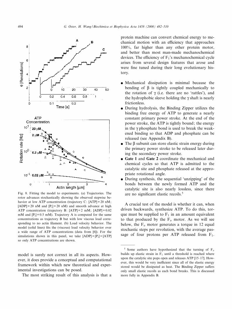
model is surely not correct in all its aspects. How-ever, it does provide a conceptual and computationalframework within which new theoretical and exper-imental investigations can be posed.
The most striking result of this analysis is that a
protein machine can convert chemical energy to me-chanical motion with an e¤ciency that approaches100%, far higher than any other protein motor,and better than most man-made mechanochemicaldevices. The e¤ciency of F1's mechanochemical cyclearises from several design features that arose andwere ¢ne tuned during their long evolutionary his-tory.
b Mechanical dissipation is minimal because thebending of L is tightly coupled mechanically tothe rotation of Q (i.e. there are no `rattles'), andthe hydrophobic sleeve holding the Q shaft is nearlyfrictionless.
b During hydrolysis, the Binding Zipper utilizes thebinding free energy of ATP to generate a nearlyconstant primary power stroke. At the end of thepower stroke, the ATP is tightly bound; the energyin the Q phosphate bond is used to break the weak-ened binding so that ADP and phosphate can bereleased (see Appendix B).
b The L subunit can store elastic strain energy duringthe primary power stroke to be released later dur-ing the secondary power stroke.
b Gate 1 and Gate 2 coordinate the mechanical andchemical cycles so that ATP is admitted to thecatalytic site and phosphate released at the appro-priate rotational angle.
b During synthesis, the sequential `unzipping' of thebonds between the newly formed ATP and thecatalytic site is also nearly lossless, since thereare no signi¢cant elastic recoils.5
A crucial test of the model is whether it can, whendriven backwards, synthesize ATP. To do this, tor-que must be supplied to F1 in an amount equivalentto that produced by the Fo motor. As we will seebelow, the Fo motor generates a torque in 12 equalstochastic steps per revolution, with the average pas-sage of four protons per ATP released from F1.
Fig. 8. Fitting the model to experiments. (a) Trajectories. Therotor advances stochastically showing the observed stepwise be-havior at low ATP concentration (trajectory C: [ATP] = 20 nM;[ADP] = 20 nM and [Pi] = 20 nM) and smooth advance at highATP concentration (trajectory B: [ATP] = 2 mM; [ADP] = 0.02mM and [Pi] = 0.5 mM). Trajectory A is computed for the sameconcentrations as trajectory B but with low viscous load corre-sponding to no actin ¢lament. (b) Load velocity behavior. Themodel (solid lines) ¢ts the (viscous) load velocity behavior overa wide range of ATP concentrations (data from [6]). For thesimulations shown in this panel, we take [ADP] = [Pi] = [ATP]so only ATP concentrations are shown.
5 Some authors have hypothesized that the turning of Fo
builds up elastic strain in F1 until a threshold is reached whereupon the catalytic site pops open and releases ATP [15^17]. How-ever, this would be very ine¤cient since all of the elastic energystored would be dissipated as heat. The Binding Zipper su¡ersonly small elastic recoils as each bond breaks. This is discussedmore fully in Appendix B.
BBABIO 44855 24-5-00 Cyaan Magenta Geel Zwart
G. Oster, H. Wang / Biochimica et Biophysica Acta 1458 (2000) 482^510494

Moreover, because of the elastic coupling betweenthe rotor and stator (Fig. 9a), the torque seen byF1 is nearly constant. Fig. 9b shows that when theF1 synthesizer is coupled to the Fo motor which isdriven by a proton motive force of 220 mV (thephysiological proton motive force in mitochondria),it can indeed produce ATP at the observed rate.However, in order to do this the model must bemodi¢ed in a particular way.
Fig. 6b shows the elastic potentials for synthesis.Comparing them with Fig. 6a, synthesis requires abump on the ADP potential to hold up rotation of Quntil Pi binds. Is this an ad hoc addition? The experi-ments on the F1 motor were carried out in the ab-sence of the O subunit, which forms part of the shaft,along with the Q subunit, and which interacts withthe DELSEED region on L. The presence of theO subunit is necessary to interact with the DELSEEDregion on L to hold up the rotation of Q until phos-phate binds. Interestingly, the F1 motor turns some-what slower when the actin ¢lament is attached tothe O subunit rather than the Q subunit [21]. This maybe due to the additional interaction between the NOand L subunits. Adding these bumps to the F1 motorpotentials in Fig. 6a does not a¡ect the motor per-formance very much, which accords with the experi-ments reported in the presence of O [21].
As we will see below, the Fo motor delivers torqueto F1 in 12 equal stochastic steps. However, in orderto maximize the e¤ciency of ATP synthesis, theBinding Zipper must be reversed so that ATP bind-ing is weakened one hydrogen bond at a time by thetorque generated in Fo. In this way, energy is deliv-ered gradually from Fo to the catalytic site and isstored in the form of ATP binding free energy before
the ATP dissociates, carrying the binding free energywith it. To accomplish this the coupling between Fo
and F1 must be elastic; that is, the Q and b subunitsmust not be rigid. As we discuss in Appendix C, theelastic coupling between Fo and F1 is not used tostore energy from several steps of Fo and deliver itall at once to the catalytic site. Rather, this elasticitysmoothes out the energy transduction by taking thestochastic stepwise torque from Fo and delivering itsmoothly ^ and thus more e¤ciently ^ to the cata-lytic sites in F1 permitting the bonds to be brokensequentially and with minimum dissipation.
C
Fig. 9. (a) Elastic coupling between Fo and F1. Because torqueis developed at the rotor^stator interface the rotor and statortend to counter-rotate. The torsional elasticity of Q and thebending and stretching elasticity of b2 create an elastic couplingbetween Fo and F1 that smoothes out the stochastic progressionof the Fo motor. Thus during synthesis, F1 sees a nearly con-stant torque from Fo. In F1 this constant torque releases ATPfrom the catalytic site by unzipping the bonds in a nearly loss-less process. (b) When driven by a constant torque generated inthe Fo motor with a proton motive force of 220 mV, the modelsynthesizes ATP at the correct rate (shaded band). The concen-trations are [ATP] = 0.2 mM, [ADP] = 0.1 mM and [Pi] = 2 mM.
BBABIO 44855 24-5-00 Cyaan Magenta Geel Zwart
G. Oster, H. Wang / Biochimica et Biophysica Acta 1458 (2000) 482^510 495

3. The Fo motor
The Fo portion of ATP synthase is also a rotaryengine, but it draws its energy not from the hydro-lysis cycle of ATP, but from the chemical energystored in a transmembrane proton motive force. Atequilibrium, thermodynamics gives equal weight tothe concentration and electrical components of theproton motive force (pmf):
pmfrvGkBT
� 32:3vpH� ekBT
� �vi �6�
where e is the electronic charge, vi is the transmem-brane potential, and vG is the free energy in units ofkBT. However, this equilibrium equation says noth-ing about how the two components contribute dur-ing the non-equilibrium operation; this depends onthe mechanism of energy conversion. We will presenta model that encompasses most of the known exper-imental data on the Fo motor, and that ful¢lls therequirement that it generates the appropriate torqueto release nucleotide from the F1 catalytic sites.Moreover, when supplied with torque from the F1
motor, it becomes an ion pump. This reversibility isimportant for bacteria which ¢nd themselves in an-aerobic conditions, and it supports the strong struc-tural similarities between the F-ATPases and theircousins, the V-ATPase proton pumps.
Modeling the Fo motor presents an entirely di¡er-ent problem from the F1 motor. First, the atomic
structure of Fo has not been solved, and so structuralinformation is restricted to transmembrane topolo-gies inferred from amino acid sequences for the aand c subunits, and to solution structures inferredfrom NMR studies. However, mutation experimentshave isolated the critical amino acids, and extensivethermodynamic and kinetic studies have determinedthe energetics and many of the kinetic rates associ-ated with ATP synthesis. Nevertheless, without mo-lecular structures, model building is a more specula-tive enterprise. We have presented two versions ofthe Fo motor based on somewhat di¡erent inferredstructures for the rotor and stator of the proton andsodium driven motors [1,3]. However, the basic op-erating principle is the same for both, and the me-chanochemical performance of both are nearly iden-tical. Here we will base our presentation on thesodium motor of P. modestum because additionalexperimental information is available for it that bearson the role of the membrane potential in torque gen-eration [3,22^26]. A complete account of the mathe-matical model can be found in the web supplemen-tary material of the above references.
In constructing the Fo motor model we will notexactly parallel our treatment of the F1 motor sincethe kinematics and dynamics cannot be as cleanlyseparated because Brownian motion enters into thedynamics in a much more central and interesting waythan in the F1 motor.
Fig. 10. The rotor^stator structure and energetics. (a) Schematic of the rotor^stator assembly in P. modestum. The rotor section belowthe level of the membrane contains the 12 ion binding sites. The stator contains an aqueous channel that conducts ions from the peri-plasmic (positive) reservoir to the level of the ion binding sites. The positive stator charge, R227, blocks leakage of ions along the po-lar strip at the right connecting the aqueous channel to the cytoplasm. (b) Face-on view of the rotor^stator assembly. Rotation duringATP synthesis is to the left. Ions from the periplasmic reservoir can access the rotor sites within the aqueous channel, but ions canonly exit to the cytoplasm by boarding a rotor site and passing through the dielectric barrier forming the left wall of the channel. Ifthe occupied site moves to the right, it quickly loses its ion back to the channel when it approaches the positive stator charge, R227.(c) Free energy diagram of one rotor site as it passes through the rotor^stator interface. Ion binding and dissociation to the rotor siteswitch the potentials between that corresponding to an empty site (solid line) and an occupied site (dashed line). 1C2: the rotor sitejust outside the stator di¡uses to the left bringing the empty (negatively charged) site into the attractive ¢eld of the positive statorcharge (R227) which pulls it into the stator. 2C3: the membrane potential biases the thermal escape of the site to the left by tiltingthe potential and lowering the left edge. 3C4: the site quickly picks up an ion from the periplasmic channel. This switches the site tothe occupied (dashed) potential. 4C5: the occupied rotor site can now pass through the dielectric barrier, driven by di¡usion and thepulling of the next rotor site towards the stator charge. If the site di¡uses to the right, either the ion dissociates as it approaches thestator charge, or if it di¡uses into the interface, it is re£ected by the repulsion between the stator charge and the occupied site dipole.5C6: upon exiting the stator the site quickly loses its ion. Now charged, the site sees the stator dielectric barrier which prevents backdi¡usion. The cycle decreases the free energy of the system by an amount equal to the electromotive force: vW=vi32.3(RT/F)vpNa,where F is the Faraday constant. The free energy changes accompanying ion binding from the periplasm and dissociation to the cyto-plasm are vGP and vGC, respectively.
C
BBABIO 44855 24-5-00 Cyaan Magenta Geel Zwart
G. Oster, H. Wang / Biochimica et Biophysica Acta 1458 (2000) 482^510496

3.1. Geometry of the rotor and the stator
Fig. 10 is a cartoon summarizing a consensus viewof the geometry of the counter-rotating a (stator) andc12 (rotor) structures of P. modestum [3]. The centralfeatures of this organization are:
b There are 12 ion binding sites on the rotor, eachconsisting of the triplet of charges (Glu65, Gln32,Ser66). The binding sites are located below thelevel of the membrane, so that sites outside therotor^stator interface are in equilibrium with the
BBABIO 44855 24-5-00 Cyaan Magenta Geel Zwart
G. Oster, H. Wang / Biochimica et Biophysica Acta 1458 (2000) 482^510 497

cytoplasmic reservoir. Mutations at these sites canswitch the allegience of the rotor from sodium tolithium to protons. This means that the rotor sitecan be treated as a simple Coulomb well.
b There is one critical basic charge on the stator,Arg227, and several polar groups £anking it.
b The pattern of polar groups suggests that the inpution channel penetrates the stator to the lower levelof the membrane. Moreover, there is a strip ofpolar residues on the right side of the channel con-necting the lower end of the input channel to thecytoplasm.
b The rotor^stator interface is hydrophobic exceptfor the input channel and the horizontal strip.The hydrophobic interface prevents leakage ofions from the acidic to basic reservoirs. Becauseof the stator charge, ions cannot pass throughthe polar strip. However, a rotor site that hasnot bound a sodium ion can pass into the rotor^stator interface along the strip. A site that hasbound an ion is treated as a dipole, and is su¤-ciently neutralized that it can pass through thehydrophobic interface on the left side of the chan-nel.
Below we will show that the predominant path ofions is to board a rotor site from the input channel,rotate with the rotor site through the hydrophobicregion (to the left in Fig. 10), and dissociate into thecytoplasm.
3.2. Dynamics: electrostatic forces and Brownianmotion drive the rotor
The rotor and stator interact through Coulombforces that depend on the ionization state of the ro-tor sites. Only the sites within and adjacent to thestator a¡ect the rotor motion. Based on the numberof K helices constituting the a subunit deduced fromthe sequence data we assume that the stator spans tworotor sites. Therefore, the rotor^stator interaction isdetermined by the ionization state of four rotor sites:two sites within the stator and two sites adjacentlaterally. Thus the chemical state of the rotor^statorassembly, which we denote as before by s, has 24 = 16states because each of these four sites may be emptyor occupied. Transitions between states occur whenan ion binds to or dissociates from a rotor site. Since
the relaxation to equilibrium after an association/dis-sociation event is much faster than the association/dissociation rates and the mechanical motion, we cantreat the transitions between these states as a Mar-kov chain just as before, leading to chemical dynam-ics similar to Eq. 2. Because of the electrostatic in-teractions between the rotor sites and the statorcharge (Arg227), the transitions between states de-pend on the angular position of the rotor.
The dynamical equations for the motion of therotor look formally like Eq. 1; however, the naturesof the driving torques are quite di¡erent [3] :
�7�
The torques on the right hand side depend on therotation angle, a, and the ionization state of the ro-tor sites, s :
b dQ(a,s) is due to the electrostatic interaction be-tween the stator charge (R227) and the rotor sitesthat are within or adjacent to the hydrophilic ro-tor^stator strip. An unoccupied (charged) site willbe attracted by the stator charge according toCoulomb's law corresponding to the dielectricand shielding environment of the stator.
b dvi(a,s) is due to the membrane potential dropacross the horizontal polar strip connecting theinput channel and the stator boundary.
b dD(a,s) is the electrostatic barrier that opposes theentry of a charged site into the hydrophobic rotor^stator interface. This barrier arises from di¡erencein dielectric constant between the aqueous channeland the rotor^stator interface. Thus a rotor sitemust be dehydrated in order to enter the rotor^stator interface, introducing a free energy barriermuch larger than 20 kBT. This means that thebarrier can be treated as essentially in¢nite sincethe proton motive force is much smaller than thedielectric barrier.
b dRS(a) is the passive rotor^stator interaction thatarises from the bumpy interface between the rotorand stator and from electrostatic interactions (oth-er than the interaction between the rotor bindingsites and the stator charge R227). This interaction
BBABIO 44855 24-5-00 Cyaan Magenta Geel Zwart
G. Oster, H. Wang / Biochimica et Biophysica Acta 1458 (2000) 482^510498

may be required to prevent Brownian £uctuationsnormal to the interface from allowing ion leakagethrough the interface.
b dF1 (a) is the load torque from F1 opposing therotor motion. This torque equals to that deliveredfrom Fo to F1 to power ATP synthesis.
b dB(t) is the random Brownian torque due to thethermal £uctuations of the rotor.
The quantitative dynamical behavior of the rotor isdescribed by the solutions to Eqs. 2 and 7. We canget a qualitative idea of how the forces and reactionsconspire to drive the rotor by examining the poten-tial ¢elds experienced by a rotor site as it passesthrough the rotor^stator interface. Fig. 10c showsthe free energy of a rotor site as it moves throughthe stator. The ¢gure caption explains how the bind-ing and dissociation of ions to the rotor site switchesthe electrostatic potential seen by the rotor, whichbiases the rotor's di¡usion to the left. Note thatthe potential drop across the polar strip can beviewed as a `power stroke'; however, in the absenceof rotor di¡usion it cannot drive the motor to theleft. Rather, it biases the thermal escape of the rotorto the left. In the computations here we have as-sumed that the input channel is aqueous, so thatall of the membrane potential drop occurs acrossthe polar strip. Placing some or all of the potentialdrop across the input channel increases the e¡ectiveion concentration seen by the rotor site, and thuschanges the equilibrium binding constant to the rotorsites.
Fig. 11. The performance of the motor and the pump. (a) Loadvelocity behavior when the passive rotor^stator interaction issmall (dRS in Eq. 7). In this case, the Fo motor produces su¤-cient torque to generate ATP in F1 (shaded band). The mem-brane potential and concentration di¡erence contribute aboutequally to torque generation near the operating point. (b) Loadvelocity behavior when the passive rotor^stator interaction, dRS,is signi¢cant. In this situation the requisite torque is providedalmost entirely by the membrane potential. This appears to bethe case for the P. modestum sodium motor. In both (a) and(b), the solid lines are for the case where the motor is drivensolely by the membrane potential (vi= 200 mV, vpNa = 0); thedashed lines are for the case where the motor is driven solelyby the concentration di¡erence (vi= 0, vpNa = 200 mV). Herethe passive interaction potential is chosen to enhance the seiz-ure of negative empty rotor sites by the positive stator charge.Without the help of the membrane potential, empty rotor sitescannot jump out of the potential well. (c) The FO pump. Whenthe electromotive force is not large enough to counter the tor-que generated by the F1 motor, Fo is turned backwards andpumps ions up the electromotive gradient. The curve shows thepump performance as a function of an opposing membrane po-tential when the sodium concentration is 1 mM on both sidesof the membrane. pH regulation by the V-ATPase is discussedin detail in [32].6
BBABIO 44855 24-5-00 Cyaan Magenta Geel Zwart
G. Oster, H. Wang / Biochimica et Biophysica Acta 1458 (2000) 482^510 499

3.3. Coupling Fo and F1 : the ion turbine and the ionpump
The Fo motor model acts as an `ion turbine' toconvert the free energy stored in the transmembraneproton motive force into rotary torque. Does themechanism we have described generate su¤cient tor-que to synthesize ATP? Before answering this ques-tion we must address the issue of how Fo is coupledto F1.
As shown in Fig. 9a, the counter-rotating rotorand stator of Fo are coupled through the Q shaftand the b subunits to the rotor and stator of F1. Ifall components were rigid then the stepwise progres-sion of the Fo rotor would be communicated directlyto F1, and the unbending of the L subunits wouldtake place in steps as well. However, proteins are notrigid bodies, and the coupling between Fo and F1 iscertainly not rigid, for the Q coiled coil has sometorsional elasticity and the b2 stalk that connectsthe a subunit to the K3L3 hexamer is £exible aswell. This elasticity permits much more e¤cient me-chanochemical coupling between Fo and F1. The rea-son is that placing an elastic element between thetorque generated in Fo and the load from F1
smoothes out the rotor steps allowing a nearly con-stant torque to be delivered to F1. Since the moste¤cient way to transmit energy is via a constanttorque (see Appendix A), an elastic coupling betweenFo and F1 is energetically more e¤cient. Fig. 6cshows the load potential from F1 seen by the Fo
motor. In Appendix C we discuss more generallyhow elastic coupling a¡ects energy conversion e¤-ciency in ATP synthase.
Fig. 11 shows load velocity curves for two situa-tions: when the passive rotor^stator interaction isweak or strong. The top panel shows that when thepassive force holding the rotor and stator in registeris weak, the Fo motor can generate the 45 pNWnm oftorque required to turn F1 backwards and releasenewly synthesized ATP from the catalytic site. Inthis situation, the contributions of the membranepotential (vi) and the concentration di¡erence(vpNa) at the operating conditions are about thesame. The middle panel in Fig. 11 shows the situa-tion where the passive rotor^stator interaction isstrong. Now the torque is generated almost com-pletely by the membrane potential. This appears to
be the situation in the sodium motor of P. modestum,and perhaps in other Fo-ATPases as well [27].
The e¤ciency of the Fo motor is de¢ned as theratio of the energy output to the energy consumed.The energy output per step is dLoadU2Z/12. At phys-iological pH and membrane potential rotation of themotor is tightly coupled to the proton £ux. There-fore, the energy consumed per step is given by theproton motive force, vW. Thus the e¤ciency is givenby the ratio of the energy output per step to the freeenergy drop per proton passing through the stator:(dLoadU2Z/12)/vWV70%.
3.3.1. The proton Fo motorThe model we have described here was designed to
explain the sodium powered Fo motor of P. modes-tum. In an earlier study we described the proton Fo
motors of mitochondria and Escherichia coli basedon a somewhat di¡erent geometry [1]. The principledi¡erence between the two motors lies in the locationof the rotor sites. The proton Fo model was based ona subunit c structure in which the proton bindingsites appeared to be within the membrane spanningregion [28,29], whereas in the sodium motor modelthe sites lie below the level of the membrane, and soare in equilibrium with the cytoplasm. To accommo-date this di¡erence the proton Fo rotor was modeledwith two half channels rather than one. This requiresa proton entering the input channel to board therotor and ride with it around a complete circuit be-fore dissociating into the exit channel. In the twohalf channel model for the proton driven motor,we assumed that the membrane potential spans theproton channels in the direction perpendicular to ro-tor motion [1]. Nevertheless, the two designs (the onehalf channel model and the two half channel model)operate on the same principle and have the samemechanical properties [3]. The torque generationmodel cannot distinguish between the mechanical be-havior of the one and two channel models becausetorque is generated at the rotor^stator interface.Therefore, when a proton leaves the interface,whether or not it dissociates or travels a completecircuit before dissociating has no e¡ect on torquegeneration. However, an important di¡erence be-tween the two models is that the two channel modelcannot explain the sodium exchange experiments[30,31]. Yet individual subunits from E. coli and
BBABIO 44855 24-5-00 Cyaan Magenta Geel Zwart
G. Oster, H. Wang / Biochimica et Biophysica Acta 1458 (2000) 482^510500

P. modestum can be assembled into functional hy-brids. Thus puzzling anomalies remain that mustawait resolution until an unambiguous structure isavailable.
Finally, just as the F1 motor could be driven inreverse to synthesize ATP, the Fo motor can be driv-en in reverse to perform as an ion pump. Indeed, theclosely related V-ATPase proton pumps function inexactly this way [32]. The bottom panel of Fig. 11shows the performance of the Fo sodium motor as anion pump when F1 supplies torque to reverse its ro-tation direction.
4. Summary: the principles of mechanochemicalenergy conversion in ATP synthase
In this review we have presented our view of howATP synthase converts chemical energy into rota-tional motion. It accomplishes this conversion intwo dramatically di¡erent ways. The F1 motor oper-ates at very high mechanochemical e¤ciency. Thusjust as chemical kinetics and thermodynamics placeconstraints on biochemistry (e.g. detailed balance,overall free energy decrease), so does the high e¤-ciency of F1 place mechanical constraints on how thefree energy of ATP hydrolysis is converted into me-chanical force. In particular, this high e¤ciency re-quires that the hydrolysis cycle generates a nearlyconstant torque. Furthermore, the structure of theK3L3Q assembly must couple the conformationalchanges accompanying nucleotide binding to the ro-tation of the Q shaft by a tight mechanical escape-ment that allows few `rattles' or friction that woulddissipate energy. To accomplish this the enzyme mustbind ATP in a particularly e¤cient way, which wehave called the `Binding Zipper'. This requires thebinding of ATP to the catalytic site proceeds sequen-tially, bond by bond, during which the binding en-ergy is converted continuously into bending stress inL. This mechanism permits the catalytic site to gen-erate the required constant mechanical force thatdrives the power stroke while at the same time stor-ing elastic energy for later release. Finally, synchro-nization of the hydrolysis cycle with rotation of Qrequired the equivalent of a camshaft and distributorthat could control the angular position of Q at whichATP could gain access to the catalytic site to initiate
the primary power stroke, and later to release phos-phate at just the right time to allow the elastic recoilof the secondary power stroke to assist the next cat-alytic `cylinder' in its primary power stroke. TheGate 1 and Gate 2 regions on Q are one way toprovide this function, but we have suggested otherpossibilities as well.
By contrast, the Fo motor is faced with the task ofconverting energy stored in a transmembrane electro-chemical gradient into rotary torque. Fo solves thisproblem by allowing the ions ^ protons or sodium ^to hop on and o¡ rotating acidic residues and, in sodoing, switch the local electrostatic ¢eld on and o¡.Because of the special geometry of the rotor^statorinterface, this `£ashing' electrostatic ¢eld `recti¢es'the Brownian motion of the rotor, so that the rotordi¡uses predominantly in one direction. When anappreciable membrane voltage is present, the motortakes on a hybrid quality with characteristics of botha Brownian ratchet and a power stroke.
Do these principles generalize to other molecularmotors? One is tempted to say yes, because othermotors such as kinesin, myosin, and dynein involvenucleotide hydrolysis [33^35]. However, there areseveral important di¡erences between these motorsand F1. Most important, F1 is a rotary engine thatdoes not bind to the Q shaft as it rotates. The linearmotors involve a mechanochemical cycle which alter-nates between strong and weak binding to an actinor microtubule track. For linear motors, energy mustbe passed between the catalytic and track bindingsites. Finally, no linear motor approaches the near100% e¤ciency that so constrained our choices inmodel building, in part because their cycles involveconsiderable di¡usive motions which are absent in F1
[35^38]. DNA helicases, and RNA polymerase arehydrolysis driven rotary motors, but their structuraldissimilarities to F1 make comparisons di¤cult [39^41]. So it remains to be demonstrated whether any ofthe ingredients of the F1 motor model, such as theBinding Zipper, and the elastic recoil power stroke,are used by other hydrolysis driven motors.
Many questions remain to be answered about thefunctioning of ATP synthase. For example, what arethe structural bases for the ATP and phosphorusgates? All the model can assert is that they are nec-essary for the motor's operation.
The Fo motor would appear to be a good para-
BBABIO 44855 24-5-00 Cyaan Magenta Geel Zwart
G. Oster, H. Wang / Biochimica et Biophysica Acta 1458 (2000) 482^510 501

digm for the bacterial £agellar motor. Both are ro-tary engines that can be driven by protons or so-dium, and both can be fueled by any combinationof vpH and a membrane potential. However, thereare striking di¡erences which must be resolved beforeone can extrapolate from Fo to the £agellar motor.First, the £agellar motor generates a far greater tor-que than Fo ; much more than can be easily ac-counted for by employing 8^12 stators. Second, theFo mechanism depended on having a collection ofrotating ion bearing sites whose ionization statecould implement the di¡usion ratchet. Recent muta-tional work on the £agellar motor suggests that therotor may not be ionized [42^44]. Finally, the loadvelocity behavior of the £agellar motor is very di¡er-ent from Fo in ways that are di¤cult to reconcile[45,46]. All of these obstacles may be overcome even-tually, and we may come to see the two as mecha-nistically related in accordance with the view thatthey are evolutionarily related as well. Or it may bethat nature has many tricks up its sleeve when itcomes to energy transduction.
Regardless of whether the principles enunciatedhere extrapolate to other molecular motors, wehope that the methodology we have employed fortreating coupled mechanical and chemical processesin motor proteins will prove useful to others.
Acknowledgements
The authors would like to thank Kazuhiko Kino-sita for his insightful comments on the F1 model, andPeter Dimroth for his collaboration on the sodiumFo motor and for his helpful comments on thismanuscript. G.O. and H.W. were supported byNSF Grant DMS-9626104.
Appendix A. Implications of the high mechanicale¤ciency of F1
In this appendix we show that a corollary of thehigh measured e¤ciency is that the torque generatedby the F1 motor is nearly uniform, independent ofthe rotational position.
In the experiments carried out by Yoshida andKinosita's groups, an isolated K3L3Q hydrolyzed
ATP and drove the rotation of a long actin ¢lamentattached to the Q shaft [6,7]. When the ATP concen-tration was high, the e¤ciency of the F1 motor wasestimated to be near 100% [6,7,47]. They de¢ned ef-¢ciency as the ratio of the `average energy' dissipatedper step (rotation by 2Z/3) divided by the hydrolysisfree energy of ATP. Thus one concludes that theinternal energy dissipation by the F1 motor mustbe very small. In other words, almost all of theATP hydrolysis free energy goes into generating thetorque driving the rotation of the ¢lament. This state-ment may appear trivial since the F1 motor (diameterV10 nm) is very small compared to the ¢lament(1V2 Wm) it is driving. Indeed the energy dissipatedby the rotating Q shaft alone (excluding the long actin¢lament) is negligible in comparison with the energydissipated by the rotating ¢lament.
The key issue raised by this conclusion concernsthe mechanical coupling. If ATP hydrolysis is nottightly coupled to the hinge bending of L, and/orthe bending motion of L is not tightly coupled tothe rotation of the Q shaft, a substantial fraction ofthe energy will be dissipated to the surrounding £uid.Thus all moving components of the F1 motor must betightly coupled ^ that is, no rattling about ^ and themechanical motions must be tightly coupled to thechemical reaction.
However, this is not the only conclusion we candraw from the near 100% e¤ciency. The `averageenergy' dissipated per step by the rotating ¢lamentwas calculated as
�8�
where Ggf is the average of velocity for one motorover long time, or equivalently the average of veloc-ity at one time over an ensemble of motors. Yasudaet al. estimated the e¤ciency as [6] :
RrvEEST
3vGATP� jGgfW2Z=3
3vGATPV100% �9�
Yasuda et al. ¢t their data with a simple model thatassumed a constant torque [6]. Here we demonstratebelow by a simple example that Eq. 9 implies that thetorque generated by the F1 motor is nearly constant,independent of the rotation angle, a.
We consider the situation of a horizontal actin
BBABIO 44855 24-5-00 Cyaan Magenta Geel Zwart
G. Oster, H. Wang / Biochimica et Biophysica Acta 1458 (2000) 482^510502

¢lament rotating around a vertical axis at one end asin the experimental setup [6,7]. The length of the¢lament is L = 2.5 Wm, comparable to those used inthe experiments. The rotational drag coe¤cient ofthe ¢lament, j, is given by [48]
j � 4Z3
RWL3
logL2r
� �30:447
�10�
where R= 1039 pNWsWnm32 is the viscosity of waterand r = 5 nm is the radius of the ¢lament.
We consider the simple case where the internaldissipation is zero so that all the free energy ofATP hydrolysis goes into driving the rotation ofthe actin ¢lament. We model this problem as a ¢la-ment driven by a tilted potential VDrive(a) satisfying
VDrive�a� � V�a� � vGATP
2Z=3Wa �11�
where V(a) is periodic with period 2Z/3. That is, the¢lament is driven by a constant torque d0 =3vGATP/(2Z/3) plus a `bump' potential V(a). Here we takevGATP =323 kBT so that d0 = 45 pNWnm. The sto-chastic motion of the ¢lament is described by a Lan-gevin equation [49]:
�12�
In the absence of the bump potential (i.e. VP= 0),the average angular velocity is
Gg0; f � d0
j�13�
The available free energy for driving the ¢lament canbe written in terms of Gg0f as
vG � VDrive�0�3VDrive2Z3
� �� d0W
2Z3� jGg0fW
2Z3
�14�The e¤ciency de¢ned in [6,47] is given by
R � vEEST
vG� jGgfW2Z=3
jGg0fW2Z=3� Ggf
Gg0f�15�
Here Ggf is the average angular velocity in the pres-ence of the bump potential, and Gg0f is the average
angular velocity in the absence of the bump poten-tial. The presence of the bump potential makes thereal driving torque uneven. We now show that thebump potential always slows down the average rota-tion of the ¢lament, i.e. Ggf9Gg0f, and thus reducesthe e¤ciency. Therefore the maximum e¤ciency canonly be attained in the absence of the bump poten-tial, that is, when the driving torque is constant in-dependent of the rotational position.
For the purpose of computing statistical averagesof the ¢lament motion one can recast the Langevinequation as an equivalent Fokker^Planck equation.Let b(a,t) be the probability density that the ¢lamentis at the angular position a at time t. b(a,t) evolvesaccording to the convection di¡usion equation
�16�
where D = kBT/j is the rotational di¡usion coe¤cientof the ¢lament. Solving equation for the steady statesolution with periodic boundary conditions, we ob-tain that the average angular velocity, Ggf, is
Ggf �d0
jWZ 2Z
30
dsWexp3d0skBT
� �Z 2Z
30
dsWZ 2Z
30
daW3
2Zexp
V�s� a�3V�a�kBT
� �Wexp
3d0skBT
� �264375
�17�
The ¢rst term of the integrand in the denominatorobeys the inequality:
Z 2Z3
adaW
32Z
expV�s� a�3V�a�
kBT
� �v1 �18�
Therefore Ggf is bounded by Gg0 ;f= d0/j andGgf= Gg0f happens only in the absence of the bumppotential (i.e. VP= 0).
Fig. 12 shows that the e¤ciency used by Yasuda etal. decreases as the amplitude of the sinusoidal bumppotential increases. Fig. 13 compares a constant tor-que, a periodic torque, and a Brownian ratchet. Thisshows that a ratchet with three steps per revolutioncannot achieve the measured e¤ciency. With moresteps, the ratchet e¤ciency increases, but only ap-
BBABIO 44855 24-5-00 Cyaan Magenta Geel Zwart
G. Oster, H. Wang / Biochimica et Biophysica Acta 1458 (2000) 482^510 503

proaches that of a constant torque when the numberof steps gets very large.
Appendix B. The `Binding Zipper'
In Appendix A we have shown that the high e¤-ciency of the F1 motor required the power stroke togenerate a nearly constant torque. In order to ac-complish this, we had to assume that when ATPbinds to the catalytic site it does so in a progressivefashion that we have called the `Binding Zipper'. Inthis picture, the sequential formation of bonds be-tween ATP and the catalytic site is tightly coupledto the hinge bending motion of L. The initial bindingof ATP to the catalytic site is weak, involving only asingle bond, or hydrophobic region. The bendingmotion of L commences with the second bond, andcompletes after all bonds have been formed, where-upon ATP is bound tightly to the catalytic site. Gen-erally, the weakly bound state of ATP will be shortlived because the binding transition from weak totight happens quickly as other bonds quickly form.When there is little or no resistance to the bending ofL, the binding transition proceeds very quickly to thetightly bound state. However, when there is resis-tance to the bending of L from a load torque, thebinding transition can be stopped at an intermediatestate by stopping the bending motion of L. Since thebending of L is mechanically coupled tightly to therotation of Q, stopping rotation should arrest ATP inan intermediate bound state.
During synthesis, the Fo motor turns Q in the op-posite direction and the bending cycle of L is re-versed. The bonds holding ATP in place are brokensequentially, and ATP binding a¤nity is reduced insmall steps. Several authors have suggested that thetorque generated in Fo is used to compress a spring,and when the accumulated energy exceeds a thresh-old, it is used to suddenly spring open the catalyticsite [15^17]. However, such a mechanism will dissi-pate a large portion of the stored elastic energy asthe spring recoils. This is very ine¤cient. Here wecompare this idea with the `Binding Zipper' de-scribed above.
Because the binding a¤nity of ATP can changegradually, the interaction between ATP and the cat-alytic site cannot be described by a two state model:
[bound]H[unbound]. The binding a¤nity is directlyrelated to the free energy of the system (ATP+cata-lytic site). If we model the interaction between theATP and the catalytic site using a two state model,the binding a¤nity of ATP will jump from beingweakly bound to being tightly bound. This suddenjump in binding a¤nity corresponds to a suddenjump in the free energy of the system (ATP+catalyticsite). In the hydrolysis direction, this sudden jump infree energy is inconsistent with the nearly constanttorque of the F1 motor measured in the experiments[6], since a sudden free energy drop cannot be con-verted into a constant torque with nearly 100% e¤-ciency. In the synthesis direction, a two state modelrequires that the energy supply from the Fo motor beaccumulated until enough energy is stored to accom-modate a sudden drop in ATP binding a¤nity. It isnot clear how this could be accomplished. It has beenproposed that the energy is stored in an elastic springand then is used to power the ATP binding a¤nityjump [15^17]. However, after the jump, most of theenergy stored in the spring will be dissipated as thespring recoils, so this is a dramatically ine¤cientmechanism.
However, if we allow the ATP binding a¤nity tochange gradually, we can generate a nearly constant
Fig. 12. E¤ciency as a function of the amplitude of the bumppotential. A ¢lament is driven by a constant torque plus an ad-ditional periodic `bump' potential. The `e¤ciency' is de¢ned as:(average drag torque on the ¢lamentUdisplacement)/(availablefree energy). The amplitude of the bump potential measures thedeviation of the actual driving torque from a constant torque.This curve demonstrates that the maximum e¤ciency isachieved when the driving torque is constant.
BBABIO 44855 24-5-00 Cyaan Magenta Geel Zwart
G. Oster, H. Wang / Biochimica et Biophysica Acta 1458 (2000) 482^510504

torque with high e¤ciency in the hydrolysis directionand release ATP with minimum dissipation in thesynthesis direction. In the hydrolysis direction, thebinding a¤nity is increased gradually, bond bybond, so that the free energy of the system is loweredgradually and e¤ciently to generate a constant tor-que to drive the rotation of Q. In the synthesis direc-tion, the free energy level of the system (ATP+cata-lytic site) is raised gradually by the torque supplied
from the Fo motor. The binding a¤nity of ATP isdecreased gradually until thermal £uctuations candislodge the nucleotide. There is no elastic recoil ac-companying release so there is no signi¢cant energydissipation. The Binding Zipper model can be viewedas an extension of Kosland's Induced Fit model ofenzyme speci¢city to include the properties that theligand binds sequentially, and the catalytic site, while£exible, is not too elastic [50].
Fig. 13. Comparison of the e¤ciency for several cases. A ¢lament is driven by potentials (VDrive) shown in the left column. The mid-dle column shows the actual driving torques (dDrive = dVDrive/da). The right column shows the corresponding e¤ciencies de¢ned as(average drag torque on the ¢lamentUdisplacement)/(available free energy). Top row: the ¢lament is driven by a constant torque.Middle row: the ¢lament is driven by a torque with a small periodic amplitude. Bottom row: When the ¢lament is driven by a ratch-et, the driving torque is a spike (delta) function, which is very far from a constant torque. Consequently, the e¤ciency is only V9%.
BBABIO 44855 24-5-00 Cyaan Magenta Geel Zwart
G. Oster, H. Wang / Biochimica et Biophysica Acta 1458 (2000) 482^510 505

Fig. 14. Comparison of the elastic storage mechanism with the Binding Zipper. Upper panel: Schematic of the unzipping of hydrogenbonds between ATP and the catalytic site during synthesis. Middle panel : The L subunit is represented schematically by two rigidarms connected by a hinge point. The sequence shows the elastic storage mechanism for ATP release [15^17]. The upper arm is con-nected to the catalytic site by a spring. Driven by the Fo motor, the bending of L stores elastic energy until it exceeds the level re-quired to free the nucleotide, whereupon the catalytic site springs open. When this happens almost all of the elastic energy stored inthe spring is dissipated into heat as the spring recoils to its rest length. Lower panel: The Binding Zipper mechanism. As L bendsforce is applied uniformly to break the bonds between ATP and the catalytic site sequentially. In this way the ATP binding a¤nity isreduced gradually by the torque from the Fo motor. Since the catalytic site is £exible but not extensible (like a bicycle chain), littleelastic energy is stored during zipping and/or unzipping of these bonds, and consequently little energy is dissipated when bonds formor break.
BBABIO 44855 24-5-00 Cyaan Magenta Geel Zwart
G. Oster, H. Wang / Biochimica et Biophysica Acta 1458 (2000) 482^510506

The middle row of Fig. 14 depicts the process ofATP release proposed in [15^17]. It starts with theATP tightly bound on the catalytic site. When thetop part of L is pushed back by the rotation of theQ shaft it stretches the spring between the L and thecatalytic site. The L cannot release ATP until it hasaccumulated enough energy in the spring. At thatpoint, the stretched spring pulls the catalytic siteopen, which reduces the ATP binding a¤nity cata-strophically, freeing the ATP from the catalytic site.After the release of ATP, the stretched spring relaxesand a large portion of the elastic energy stored in it isdissipated into heat; thus the process is irreversibleand very ine¤cient.
The bottom row of Fig. 14 describes the BindingZipper model for ATP release. As before, ATP be-gins tightly bound in the catalytic site, with all bondsbetween the nucleotide and the catalytic site in place.As the Q shaft rotates, it bends the top part of L awayfrom the bottom part. This conformational changebreaks the bonds one by one and gradually decreasesthe nucleotide's binding a¤nity. The second andthird panels show intermediate stages where part ofthe catalytic site has been `peeled o¡' from the nu-cleotide. Note that the connections between the cat-alytic site and the rest of L are nearly rigid so thatlittle elastic energy is stored in their deformation.That is the catalytic site must be £exible, but notextensible, like a bicycle chain. As the catalytic siteis peeled o¡ from the nucleotide, the number of pos-sible bonds that can be formed decreases. Thus theunbending motion of L is directly coupled to decreas-ing the ATP binding a¤nity. At the end when all ^or nearly all ^ of the bonds between ATP and thecatalytic site are broken, a thermal £uctuation candislodge the ATP from the catalytic site allowing itto di¡use away. There is little energy dissipated uponATP release since little elastic energy was stored.
ATP binding is the reverse of this process. Uponthe arrival of ATP at the catalytic site (step 4), bondformation between nucleotide and the site commen-ces. As these bonds are being formed one by one, thecatalytic site is being pulled closed and the anglebetween the top part of L and the bottom part closes(steps 3 and 2). When all bonds are formed, thecatalytic site is closed and L has completed its bend-ing motion (step 1). Thus the Binding Zipper modelpredicts that during the ATP binding process, a
nearly constant force is generated utilizing the bind-ing free energy of ATP. For the F1 motor, part ofthis force is delivered to drive the rotation of theQ shaft and the rest of it is stored in the L subunitas an elastic energy. This stored elastic energy isreleased to drive the rotation of the Q shaft whenphosphate is released. Thus a constant force is gen-erated and delivered out of the system (ATP+cata-lytic site) during the ATP binding process. Part ofthis constant force is delivered to drive the rotationof the Q shaft and the rest of it is stored as elasticenergy in the protein structure (L subunit) surround-ing the catalytic site.
Finally, we address the question of how the energystored in the Q phosphate bond of ATP is utilized tosustain the torque generation process. At the end ofthe ATP binding process, all of the ATP binding freeenergy has been delivered out of the system (ATP+-catalytic site). The free energy of the system has fall-en by about 24 kBT and ATP is now tightly bound inthe catalytic site at the bottom of a potential well 24kBT deep. When ATP is hydrolyzed to ADP andphosphate, the tight binding can be destroyed atthe expense of the energy stored in the Q phosphatebond. The enthalpic part of the total free energy ofATP hydrolysis is 8^9 kBT, most of which can beattributed to the electrostatic repulsion between theL and Q phosphates.
One likely scenario is that the in-line attack of thewater molecule coordinated to LGlu188 in the cata-lytic site breaks the covalent phosphoanhydride bondon the Q phosphate. This unmasks the electrostaticrepulsion between ADP and Pi, each of which carriestwo net negative charges. Since the hydrogen bondsholding the products in the transition state are highlydirectional, a small misalignment reduces their bind-ing energy signi¢cantly. This electrostatic repulsion issu¤cient to disorient the hydrogen bonds holding theproducts in the transition state. In the hydrolysistransition from ATP to ADP and Pi, the free energyof the system (nucleotide+catalytic site) does notchange signi¢cantly (the equilibrium constant isabout 1). The 8^9 kBT from the electrostatic repul-sion between ADP and Pi weakens the total bindingfrom 24 kBT to 15^16 kBT. After hydrolysis, thisremaining 15^16 kBT binding is divided betweenADP and Pi so each product is held by a potentialwell 7^8 kBT deep. Thermal £uctuations are su¤-
BBABIO 44855 24-5-00 Cyaan Magenta Geel Zwart
G. Oster, H. Wang / Biochimica et Biophysica Acta 1458 (2000) 482^510 507

cient to release both products from the catalytic sitequickly once the steric block to release (Gate 2) isopened. After product release, the next cycle of thereaction can be started. To summarize: in the reac-tion cycle, the binding transition step generates atorque at the cost of 24 kBT of binding free energy.In the hydrolysis step, 8^9 kBT is provided electro-statically to switch from the tightly bound ATP stateto the loosely bound ADP+Pi state. The energy forbreaking the remaining 15^16 kBT binding comesendothermically from thermal £uctuations providedby the surroundings in two product release steps,which free the loosely bound ADP and Pi. Such en-dothemic product release steps are made energeti-cally favorable (recti¢ed) by the entropy increaseafter the products are released. This entropy increasearises from resonance stabilization of the phosphate,release of a proton, and hydration of the prod-ucts.
Overall, the free energy level of the system doesnot change much during the hydrolysis step(ATPHADPWPi). In the transition ATPCADPWPi,the Q phosphate bond energy decreases and the bind-ing free energy increases as binding weakens. In thetransition ADPWPiCATP, the energy in the Q phos-phate bond increases and the binding free energydecreases as binding tightens. The overall free energychange of the system during the transitionATPHADPWPi is small since the equilibrium con-stant is nearly unity. When the system is in ATPstate, ATP is bound tightly in the catalytic site.The major energetic step in synthesis is to use thetorque generated in Fo motor to release the tightlybound ATP from the catalytic site.
In the computational model we used a constantforce generator that is activated upon ATP dockingto model the Binding Zipper [12]. This could be mod-eled as a pre-stretched spring, which has the samephenomenological behavior as the `Binding Zipper'because it delivers a nearly constant force over itsrange of allowed displacements. If all the bonds be-tween the ATP and the catalytic site are similar, it isreasonable to expect that the `Binding Zipper' gen-erates a nearly constant force during the bindingtransition. This is surely only approximately true;however, because of Brownian motion within thecatalytic site, it is likely that all bonds have aboutthe same average energy.
Appendix C. Does elastic coupling help?
In this section, we investigate the e¡ects of elastic-ity on the e¤ciency of delivering mechanical energy.We consider two kinds of mechanical motions: uni-directional motion (e.g. the rotation of F1 or Fo) andreciprocating motion (e.g. the bending and unbend-ing of L), each of which can be coupled to elasticityin series or in parallel. Thus there are four situations,which are illustrated in Fig. 15.
Fig. 15a shows an elastic element coupling tworotating shafts in series. In this situation, the springacts as an energy bu¡er, smoothing out variations inthe input torque to deliver a nearly constant outputtorque. The weaker the elastic element, the better theenergy bu¡er. That is, a weak elastic element cantake stepwise energy input from one end and outputa nearly constant force or torque. Even if the drivingtorque is very irregular, such as that from a Brown-ian ratchet, the output torque is nearly constant.Thus an elastic element coupled in series with a uni-directional motion can increase mechanical e¤ciency.
Fig. 15b shows an elastic element coupled in par-allel to a unidirectional motion. In this situation themotion will wind up the elastic element, increasingthe resisting torque until it equals the input torqueand the motion ceases. This type of elastic couplingis not relevant for steady state energy transductionbecause it does not allow a steady state motion.
Fig. 15c shows an elastic element coupled in seriesto a reciprocating motion. In this situation the elasticelement will alternately store and release elastic en-ergy. However the elastic element decreases ratherthan increases the e¤ciency of energy transduction.When the lever moves forward, it ¢rst compresses thespring storing elastic energy before commencing todrive rotation of the wheel. However, when the leverreverses its motion, it ¢rst allows the compressedspring to recoil releasing its stored energy to drivethe motion of the lever. But during this recoil thelever is not driving the motion of the wheel. Conse-quently the elastic energy released from the spring isdissipated, and makes no contribution to the motionof the wheel. If the lever keeps moving to the left, itwill stretch the spring until the spring begins to de-liver a pulling force to the driving point on the wheel.However, the elastic energy stored in the stretchedspring will be dissipated when the piston reverses its
BBABIO 44855 24-5-00 Cyaan Magenta Geel Zwart
G. Oster, H. Wang / Biochimica et Biophysica Acta 1458 (2000) 482^510508

motion and begins to move to the right again. Theweaker the spring, the more the elastic energy isstored in the spring and so the more energy will bedissipated. Thus a weak spring coupled in series to areciprocating motion decreases the e¤ciency of en-ergy transduction.
Fig. 15d shows an elastic element coupled in par-allel to a reciprocating motion. In this con¢gurationthe spring alternately stores and releases elastic en-ergy as in the case of series coupling. When the levermoves to the right, it drives the rotation of the wheeland at the same time extends the spring storing elas-tic energy in it. When the lever reverses, the stretched
spring releases energy to help drive the lever. Sincethe level is rigidly connected to the driving point onthe wheel, the spring recoil helps to drive the rota-tion. Thus the elastic element redistributes the energyfor driving the reciprocating motion. The elastic ele-ment decreases the driving force available for for-ward motion (storing elastic energy) and increasesthe driving force available for backward motion.This may or may not increase the e¤ciency depend-ing on the speci¢c driving force for the reciprocatingmotion. When the driving force is about the same forboth the forward motion and the backward motion,the elastic element will make the driving force unevenand thus decreases e¤ciency. However, when thedriving force for the backward motion is much small-er (or even does not exist, as in a one cylinder gasengine), the elastic element can smooth out the driv-ing force by using the energy stored in forward mo-tion to drive the backward motion and thus increasesthe e¤ciency. For macroscopic engines, the job ofmaking the driving force smooth is generally accom-plished by a £ywheel. However £ywheels will notwork for molecular motors where inertial forces arenegligible.
In Fig. 15e, we identify three possible elastic ele-ments involved in the energy transduction of F-ATPsynthase. The spring at the top of the Q subunit rep-resents the torsional elasticity of the Q shaft and theelasticity of the b subunits connecting the rotor andstator of the F1 and Fo motors. This spring iscoupled in series to the unidirectional rotation ofthe Q shaft, so it helps to increase e¤ciency. Theangle spring at the hinge point of the L subunit rep-resents the elasticity of L against its hinge bendingmotion. Since this spring is coupled in parallel to thereciprocating motion (opening and closing) of thecatalytic site, it also helps to increase the e¤ciency.The spring connecting the top part of L to the cata-lytic site represents the protein structure linking thereciprocating motion of the catalytic site to the hingebending motion of L. Since this spring is coupled inseries to the reciprocating motion of the catalytic site,it decreases e¤ciency.
Note added in proof
Since submission of the ms. J. Walker's laboratory
Fig. 15. Four di¡erent situations for elastic coupling. (a) Elas-ticity coupled in series to a unidirectional motion helps to in-crease the e¤ciency. (b) Elasticity coupled in parallel to a uni-directional motion does not allow a steady state motion. (c)Elasticity coupled in series to a reciprocating motion decreasesthe e¤ciency. (d) Elasticity coupled in parallel to a reciprocatingmotion helps to increase the e¤ciency. (e) Three possible elasticelements involved in the energy transduction of F-ATP syn-thase.
BBABIO 44855 24-5-00 Cyaan Magenta Geel Zwart
G. Oster, H. Wang / Biochimica et Biophysica Acta 1458 (2000) 482^510 509

has reported a structure for the F0 subunit of thebovine mitochondrial ATP synthase: Stock, D., Les-lie, A. and Walker, J. (1999) Science 286, 1700^1705.There they report that the c-rotor consists of 10 sub-units, vs. the usually quoted number of 12. This ap-pears to require a non-integer number of protons perATP-synthesized. However, because of the elasticcoupling between F0 and F1, there is no requirementthat the number of protons/ATP be integer, and sothe principle of operation of the F0 motor remainsunchanged (c.f. Section 3.3 and Appendix C). TheWalker laboratory has also found that the O-subunitdoes not contact the DELSEED sequence on F1, ashas been previously detected by crosslinking studies.Rather the `thumb' helix region on Q forms hydrogenbonds with DELSEED, and could play the role ofthe phosphate gate (J. Walker, pers. comm.).
References
[1] T. Elston, H. Wang, G. Oster, Nature 391 (1998) 510^514.[2] H. Wang, G. Oster, Nature 396 (1998) 279^282.[3] P. Dimroth, H. Wang, M. Grabe, G. Oster, Proc. Natl.
Acad. Sci. USA 96 (1999) 4924^4929.[4] P. Boyer, Biochim. Biophys. Acta 1365 (1998) 3^9.[5] P. Boyer, Annu. Rev. Biochem. 66 (1997) 717^749.[6] R. Yasuda, H. Noji, K. Kinosita, M. Yoshida, Cell 93 (1998)
1117^1124.[7] H. Noji, R. Yasuda, M. Yoshida, K. Kinosita, Nature 386
(1997) 299^302.[8] J. Abrahams, A. Leslie, R. Lutter, J. Walker, Nature 370
(1994) 621^628.[9] P. Boyer, Biochim. Biophys. Acta 1140 (1993) 215^250.
[10] W. Allison, Acc. Chem. Res. 31 (1998) 819^826.[11] C.S. Peskin, G.M. Odell, G. Oster, Biophys. J. 65 (1993)
316^324.[12] H. Wang, T. Elston, A. Mogilner, G. Oster, Biophys. J. 74
(1998) 1186^1202.[13] A. Senior, J. Bioenerg. Biomembr. 24 (1992) 479^483.[14] J. Weber, A.E. Senior, Biochim. Biophys. Acta 1319 (1997)
19^58.[15] Y. Kagawa, T. Hamamoto, J. Bioenerg. Biomembr. 28
(1996) 421^431.[16] Y. Kagawa, T. Hamamoto, Biochem. Biophys. Res. Com-
mun. 240 (1997) 247^256.[17] D. Cherepanov, A. Mulkidjanian, W. Junge, FEBS Lett. 449
(1999) 1^6.[18] Y. Shirakihara, A.G.W. Leslie, J.P. Abrahams, J.E. Walker,
T. Ueda, Y. Sekimoto, M. Kambera, K. Saika, Y. Kagawa,M. Yoshida, Structure 5 (1997) 825^836.
[19] M. Al-Shawi, C. Ketchum, R. Nakamoto, J. Biol. Chem.272 (1997) 2300^2306.
[20] M. Al-Shawi, R. Nakamoto, Biochemistry 36 (1997) 12954^12960.
[21] Y. Kato-Yamada, H. Noji, R. Yasuda, K. Kinosita Jr., M.Yoshida, J. Biol. Chem. 273 (1998) 19375^19377.
[22] U. Matthey, G. Kaim, D. Braun, K. Wu«thrich, P. Dimroth,Eur. J. Biochem., in press.
[23] G. Kaim, U. Matthey, P. Dimroth, EMBO J. 17 (1998) 688^695.
[24] G. Kaim, P. Dimroth, Biochemistry 37 (1998) 4626^4634.[25] P. Dimroth, Biochim. Biophys. Acta 1318 (1997) 11^51.[26] G. Kaim, F. Wehrle, U. Gerike, P. Dimroth, Biochemistry
36 (1997) 9185^9194.[27] G. Kaim, P. Dimroth, EMBO J., in press.[28] M. Girvin, V. Rastogi, F. Abildgaard, J. Markley, E. Fillin-
game, Biochemistry 37 (1998) 8817^8824.[29] P. Jones, W. Jiang, R. Fillingame, J. Biol. Chem. 273 (1998)
17178^17185.[30] G. Kaim, P. Dimroth, EMBO J. 17 (1998) 5887^5895.[31] G. Kaim, P. Dimroth, FEBS Lett. 434 (1998) 57^60.[32] M. Grabe, H. Wang, G. Oster, Biophys. J., in press.[33] R. Vale, R. Fletterick, Annu. Rev. Cell. Dev. Biol. 13 (1997)
745^777.[34] T. Lohman, K. Thorn, R. Vale, Cell 93 (1998) 9^12.[35] R. Vale, J. Cell Biol. 135 (1996) 291^302.[36] E. Sablin, F. Kull, R. Cooke, R. Vale, R. Fletterick, Nature
380 (1996) 555^559.[37] M.J. Schnitzer, S.M. Block, Nature 388 (1997) 386^390.[38] C.S. Peskin, G. Oster, Biophys. J. 68 (1995) 202s^210s.[39] H. Yin, M.D. Wang, K. Svoboda, R. Landick, S.M. Block,
J. Gelles, Science 270 (1995) 1653^1657.[40] M. Wang, M. Schnitzer, H. Yin, R. Landick, J. Gelles, S.
Block, Science 282 (1998) 902^907.[41] M. Hingorani, M. Washington, K. Moore, S. Patel, Proc.
Natl. Acad. Sci. USA 94 (1997) 5012^5017.[42] J. Zhou, S. Lloyd, D. Blair, Proc. Natl. Acad. Sci. USA 95
(1998) 6436^6441.[43] R. Berry, H. Berg, Biophys. J. 76 (1999) 580^587.[44] R. Berry, H. Berg, Biophys. J. 71 (1996) 3501^3510.[45] H. Berg, Biophys. J. 68 (1995) 163s^166s.[46] H.C. Berg, L. Turner, Biophys. J. 65 (1993) 2201^2216.[47] S.M. Block, Nature 386 (1997) 217^219.[48] J. Happel, H. Brenner, Low Reynolds Number Hydrody-
namics: With Special Applications to Particulate Media,Vol. 1, Nijho¡, The Hague, 1986.
[49] H. Risken, The Fokker-Planck Equation, 2nd Edn., Spring-er-Verlag, New York, 1989.
[50] D.E. Koshland, Proc. Natl. Acad. Sci. USA 44 (1958) 98^104.
[51] K. Kinosita, R. Yasuda, H. Noji, M. Yoshida, Essays Bio-chem. 35,
BBABIO 44855 24-5-00 Cyaan Magenta Geel Zwart
G. Oster, H. Wang / Biochimica et Biophysica Acta 1458 (2000) 482^510510