revised january 1999 - citywindsor.ca
TRANSCRIPT

Revised January 1999
CITY OF WINDSOR
STANDARD SPECIFICATIONS
FOR SEWERS
TABLE OF CONTENTS
SS 1 GENERAL CLAUSES ..................................................................................................... 1
ss 1.1 ss 1.2 ss 1.3 ss 1.4 ss 1.5 ss 1.6 ss 1.7 ss 1.8 ss 1.9 ss 1.10 ss 1.11 ss 1.12 ss 1.13 ss 1.14
SCOPE ................................................................................................................. 1 WORK TO BE DONE ........................................................................................... 1 PROTECTION OF ADJACENT STRUCTURES ................................................. 1 MAINTENANCE OF FLOW .................................................................................. 2 WORK DONE IN COLD WEATHER. ......................................................................... 2 DEVIATIONS OCCASIONED BY OTHER UTILITIES OR STRUCTURE .......... 2 UTILITY SUPPORT .............................................................................................. 4 WATERMAINS AND WATER SERVICE LINES .................................................. 5 VARIATIONS IN GROUND PROFILES SHOWN ON DRAWINGS .................... 6 ASPHALT PAVER SPECIFICATIONS ................................................................. 6 PUTTING MAIN SEWER AND LATERALS INTO SERVICE .............................. 7 REMOVAL AND/OR REPAIR OF IMPROPER WORK AND MATERIALS ......... 7 SEALING OFF EXISTING SEWERS FOR SAFETY REASONS ........................ 7 PAYMENT ............................................................................................................. 7
SS 2 MATERIALS ..................................................................................................................... 8
ss 2.1 ss 2.1.1 ss 2.1.2 ss 2.2
ss 2.2.1 ss 2.2.2 ss 2.3 ss 2.3.1 ss 2.3.2 ss 2.3.3 ss 2.4 ss 2.4.1 ss 2.4.2 ss 2.4.3 ss 2.5 ss 2.5.1 ss 2.5.2 ss 2.5.3 ss 2.6
CIRCULAR CONCRETE PIPE AND FITTINGS ...................................................8 GENERAL ..............................................................................................................8 MANUFACTURE .................................................................................................. 8 PRECAST REINFORCED CONCRETE BOX CULVERTS AND BOX SEWERS ............................................................................................................... 8 GENERAL ............................................................................................................. 8 MANUFACTURE................................................................................................... 8 VITRIFIED CLAY PIPE ......................................................................................... 8 GENERAL ............................................................................................................. 8 MANUFACTURE ................................................................................................... 8 JOINTS .................................................................................................................. 8 POLYVINYL CHLORIDE (PVC) SEWER PIPE AND FITTINGS ........................ 9 GENERAL.............................................................................................................. 9 MANUFACTURE ................................................................................................... 9 JOINTS .................................................................................................................. 9 POLYETHYLENE (PE) SEWER PIPE AND FITTINGS ....................................... 9 GENERAL .............................................................................................................. 9 MANUFACTURE ................................................................................................... 9 JOINTS .................................................................................................................. 9 CORRUGATED STEEL PIPE (CSP) PRODUCTS ............................................ 10

Revised January 1999
ss 2.6.1 ss 2.6.2 ss 2.6.3 ss 2.7 ss 2.7.1 ss 2.7.2 ss 2.8 ss 2.9 ss 2.10 SS2.10.1 ss 2.10.2 ss 2.10.3 ss 2.10.4 ss 2.10.5 ss 2.10.6 ss 2.11 ss 2.11.1 ss 2.11.2 ss 2.12
GENERAL ........................................................................................................... 10 MANUFACTURE ................................................................................................. 10 JOINTS ................................................................................................................ 10 SADDLES ................................................................................................................. 10 GENERAL ........................................................................................................... 10 STRAP-ON SADDLES ........................................................................................ 10 CONCRETE ........................................................................................................ 10 PRECAST MANHOLES AND CATCHBASINS .................................................. 11 MISCELLANEOUS METAL ITEMS ................................................................... 11 STRUCTURAL STEEL ....................................................................................... 11 FRAMES, GRATES, AND COVERS ................................................................. 11 ALUMINUM ......................................................................................................... 11 GALVANIZING .................................................................................................... 11 COATINGS ......................................................................................................... 11 WELDING ........................................................................................................... 11 GRANULAR MATERIALS .................................................................................. 12 SOD AND TOPSOIL ........................................................................................... 12 ASPHALTIC CONCRETE .................................................................................. 12 LUMBER AND TIMBER ..................................................................................... 12
SS 3 CONSTRUCTION PROCEDURES ................................................................................. 13
ss 3.1 ss 3.1.1 ss 3.1.2 ss 3.1.3 ss 3.1.4
ss 3.1.5 ss 3.1.6 SS3.1.7 ss 3.1.8 ss 3.1.9 ss 3.1.10 ss 3.1.11 ss 3.1.12 ss 3.1.13 ss 3.1.14 ss 3.2 ss 3.2.1 ss 3.2.2 ss 3.2.3 ss 3.3 ss 3.3.1 ss 3.3.2 ss 3.3.3 ss 3.4 ss 3.4.1 ss 3.4.2
TRENCH EXCAVATION, BACKFILL AND COMPACTION .............................. 13 GENERAL ........................................................................................................... 13 MAXIMUM LENGTH OF OPEN TRENCH ......................................................... 13 MAXIMUM AND MINIMUM WIDTH OF TRENCH ............................................. 13 REMOVAL AND REPLACEMENT OF PAVEMENT AND OTHER SURFACE IMPROVEMENTS ............................................................................ 13 SHEATHING AND SHORING ............................................................................ 14 DEWATERING .................................................................................................... 14 DEPTH OF TRENCHES ..................................................................................... 14 DISPOSAL OF EXCAVATED MATERIAL .......................................................... 15 EXPLOSIVES AND BLASTING .......................................................................... 15 BACKFILL AND COMPACTION GENERAL ...................................................... 15 BACKFILL AND COMPACTION OF SEWER INSTALLATIONS ....................... 16 TESTING OF COMPACTION ............................................................................. 17 WATER JETTING OF MAIN SEWER TRENCHES ........................................... 17 REMOVING OF SHEATHING AND SHEET PILING ......................................... 17 INSTALLING SEWER PIPES ............................................................................. 17 BEDDING AND COVER MATERIALS ................................................................ 17 PIPING LAYING................................................................................................... 19 PIPE JOINTING .................................................................................................. 19 TUNNEL EXCAVATION AND JACKING ........................................................... 20 GENERAL ........................................................................................................... 20 TUNNELING ....................................................................................................... 20 JACKING OPERATIONS ................................................................................... 20 CONNECTIONS, PRIVATE AND CATCHBASIN .............................................. 21 PRIVATE SANITARY DRAIN CONNECTIONS ................................................. 21 PRIVATE STORM DRAIN CONNECTIONS ...................................................... 21

Revised January 1999
ss 3.4.3 ss 3.4.4 ss 3.4.5
ss 3.4.6 ss 3.4.7 ss 3.4.8
ss 3.4.9 ss 3.4.10 ss 3.4.11 ss 3.4.12 ss 3.4.13 ss 3.4.14 ss 3.5 ss 3.5.1 ss 3.5.2 ss 3.5.3 ss 3.5.4 ss 3.5.5 ss 3.5.6 ss 3.5.7 ss 3.5.8
CATCHBASIN CONNECTIONS ........................................................................ 22 CONNECTION DOUBLE STOP AT SEWER .................................................... 22 REPLACEMENT OF EXISTING PRIVATE DRAIN CONNECTIONS BEYOND TRENCH ............................................................................................ 22 EXISTING CONNECTIONS CROSSING SEWER TRENCH ........................... 23 SUPPORT FOR CONNECTION AND MAINLINE SEWER .............................. 23 BACKFILLING AND COMPACTION AROUND THE VERTICAL SECTION OF CONNECTIONS .......................................................................... 23 TAPPING OR CONNECTION INTO EXISTING SEWER ................................. 24 MECHANICAL COUPLINGS .............................................................................. 25 WATERTIGHT JOINTS AND CONNECTIONS ................................................. 25 PITS FOR PRIVATE DRAIN CONNECTIONS .................................................. 25 CONSTRUCTION ON PRIVATE PROPERTY ................................................... 25 WATER JETTING OF PRIVATE DRAIN CONNECTION PITS ......................... 26 INSTALLING MANHOLES AND CATCHBASINS ............................................. 26 GENERAL ........................................................................................................... 26 POURED IN PLACE CONSTRUCTION ............................................................. 27 PRECAST CONSTRUCTION ............................................................................. 27 INSTALLATION OF INLET AND OUTLET PIPES ............................................. 27 BACKFILL ............................................................................................................ 28 INSTALLATION OF FRAMES, GRATES AND COVERS........................................28 ADJUSTMENT OF MANHOLES AND CATCHBASINS ..................................... 28 BREAKING INTO MANHOLES AND CATCHBASINS ....................................... 29
SS 4 FIELD TESTING AND ACCEPTANCE ........................................................................... 30
SS4.1 SS4.2 ss 4.3 ss 4.3.1 ss 4.3.2 ss 4.3.3 ss 4.3.4 ss 4.4 SS4.5 SS4.6
GENERAL ............................................................................................................ 30 VISUAL INSPECTION ........................................................................................30 LEAKAGE TESTS • GRAVITY SEWERS ...........................................................30 GENERAL ........................................................................................................... 30 INFILTRATION TEST ......................................................................................... 31 EXFILTRATION TEST ........................................................................................ 31 AIR PRESSURE TEST ....................................................................................... 32 DEFLECTION TEST - PLASTIC PIPE ............................................................... 33 CAMERA INSPECTION ..................................................................................... 34 FIELD TESTING OF PIPE GREATER THAN 900MM IN DIAMETER .............. 34
SS 5 MEASUREMENT AND PAYMENT ................................................................................. 35
ss 5.1 ss 5.2 ss 5.3 ss 5.3.1 ss 5.3.2
ss 5.4 ss 5.5 ss 5.6 ss 5.7
UNIT OF MEASURE ........................................................................................... 35 MEASUREMENT OF QUANTITIES ................................................................... 35 OPEN TRENCH INSTALLATIONS ..................................................................... 35 NEW SEWERS, CONNECTIONS OR CONDUITS ........................................... 35 REPLACEMENT OR REPAIR OF EXISTING SEWERS AND CONNECTIONS ......................................................................................... 36 BORING OR JACKING INSTALLATIONS ......................................................... 36 TUNNEL INSTALLATION ................................................................................... 37 EXCAVATION AND BEDDING ........................................................................... 37 SHEATHING AND SHEET PILING ..................................................................... 37

Revised January 1999
ss 5.8 ss 5.9 ss 5.9.1 ss 5.9.2 ss 5.10 ss 5.11
RESTORATION .................................................................................................. 37 STRUCTURES ................................................................................................... 38 CATCHBASINS .................................................................................................. 38 MANHOLES ........................................................................................................ 38 ADJUSTMENTS OF MANHOLES AND CATCHBASINS....................................... 39 BREAKING INTO MANHOLES AND CATCHBASINS ...................................... 40
Revised January 1999
1
CITY OF WINDSOR
STANDARD SPECIFICATIONS FOR SEWERS
ss 1 GENERAL CLAUSES
ss 1.1 SCOPE
This specification covers the requirements for the installation of mainline sewers, lateral services including catchbasin and private drain connections, manholes, catchbasins and all other appurtenances that may be required. This specification also covers post construction connection of catchbasins, private drain connections and any repairs, replacements or alterations to the mainline sewer as a result of the above activities. The works shall be constructed as called for in the Specifications and as shown on the Contract Drawings.
The work will include:
1. Connection of mainline sewers, lateral services, and private drain
connections.
2. Temporary and permanent support for mainline sewers, lateral services and connections, sewer appurtenances including manholes and catchbasins and all other utilities which may be encountered.
3. Temporary and permanent plugs on mainline sewers, lateral services
and connections where required.
ss 1.2 WORK TO BE DONE
Unless otherwise specified herein, the prices quoted in the Form of Tender shall include the furnishing of all materials, supplies, and equipment and providing all labour, construction tools, utility and transportation services necessary to complete all the work required under the Contract.
ss 1.3 PROTECTION OF ADJACENT STRUCTURES
The Contractor shall sustain in their places and protect from injury, any and all water or gas mains, public or private sewers or drains, conduits, service pipes, sidewalks, curbs and all other structures of property in the vicinity of the work, whether over or underground, or which appear in the excavation. He shall assume all costs and expenses for damage that may be occasioned by injury to any of them.
Before excavation commences, the Contractor shall have the location of all underground utilities marked by the appropriate utility company. The

Revised January 1999
2
location of utilities shown on the contract drawings is in accordance with the best information available, but is not guaranteed.
ss 1.4 MAINTENANCE OF FLOW
The Contractor shall provide for and maintain the flow, where required, of all sewers, drains, house or inlet connections and all watercourses that may be encountered during the progress of the work. The Contractor shall not allow the contents of any sewer, drain, house or inlet connection to flow into the trench or the sewers being constructed under this contract, except where permission is given by the Engineer. If permission is granted, the Contractor shall immediately remove all offensive matter from the proximity of the work using precautions in so doing as the Engineer may direct.
ss 1.5 WORK DONE IN COLD WEATHER
The Engineer may permit or order work to be done when the air temperature is below freezing, in which case the Contractor shall heat the ingredients for concrete or mortar, furnish sufficient temporary protection and take all the necessary precautions to protect the work so that injury or damage to it will be prevented.
ss 1.6 DEVIATIONS OCCASIONED BY OTHER UTILITIES OR STRUCTURE
The Contractor shall include in his unit price bid per linear meter of sewer, the cost of all underground utility relocations required to construct the sewer except as provided for in the following cases:
1. Where the utility is a catchbasin or private drain connection (in which
case payment shall be made at the unit price bid for supplying and reconnecting connections).
2. Where the utility passes through the actual location of the proposed
sewer.
3. Where the utility is parallel to the proposed sewer and within the area defined by two vertical planes parallel to the centreline of the sewer and located equal distance from the centreline of the sewer as defined by the maximum trench width at the proposed springline of the sewer as shown on the applicable standard detail (AS series) for bedding.
4. Where the utility is parallel to the proposed sewer at a new manhole
and within the area at the manhole defined by two vertical planes parallel to the centreline of the sewer and within one foot beyond the outer face of the manhole, provided that the manhole is constructed in accordance with normal construction practices as if the utility did not exist.

Revised January 1999
3
5. Where a utility is a main and has not been shown approximately on the
drawings and this main utility is located within the theoretical trench or parallel to the proposed sewer as provided for in Subsection 3. and 4. above.
The Contractor will be responsible for the coordination of the work by the utilities companies. Payment will be made in cases 2. to 5. as an extra to the contract.
The Contractor's attention is brought to the following provisions in the General Conditions relative to utilities:
1. GC 2.02 - Accuracy of drawings as to location of structures and utilities.
2. GC 2.03 - Soundings, borings, and inspection of site.
3. GC 4.01 (X) - Cooperation with utilities, etc.
4. GC 4.05 - Access to properties adjoining the work and interruption of
utility services.
5. GC 6 - Damage to persons, property, structures, utilities, etc.
The locations and depths of the underground utilities as shown on the contract drawings are approximate only. It is the Contractor's responsibility to contact the utility agencies for further information regarding their exact locations and protection.
Utilities and their respective appurtenances that are visible from the surface shall be paid for by separate unit prices only when the requirement of relocation is clearly indicated on the contract drawings. The Contractor shall evaluate the requirements for all other required relocations of drainage culverts, surface utilities, or appurtenances thereto and provide for the cost of any relocations in his unit price bid for the sewer construction.
If an abandoned utility or sewer is encountered during excavation, when ordered, this shall be removed by the Contractor and the extra work which is required will be paid for by the Corporation as an extra to the contract, unless otherwise specified. The Corporation will not be responsible for delays in the execution of the work arising from such extra work.
Revised January 1999
4
ss 1.7 UTILITY SUPPORT
a. General
The Contractor shall note that unless otherwise specified, all utilities crossing the trench shall be maintained intact and properly supported. City of Windsor Standard Specifications S-9 and S-17 shall apply and govern except as extended or amended herein.
b. Scope
This work consists of all material, equipment, and labour required to:
11 temporarily support utility pipes crossing trenches. 111 construct concrete or acceptable equivalent utility supports.
c. Specifics
Utility supports for sewers, catchbasin leads, or private drain connections crossing the trench will not generally be required if the sewer trench is backfilled up to the crossing with clear stone or compacted granular material. If the trench is backfilled with native material, then beam supports for the sewer crossing shall be constructed of reinforced concrete in accordance with AS-312 or equivalent acceptable to the Engineer.
Utility supports for all other utilities crossing the trench shall be in accordance with the latest requirements of the utility company involved. If the Contractor is unable to ascertain the requirements of the utility companies, then the requirements of the City specifications for utility support shall apply.
Particular care shall be taken in the temporary support of these services until the permanent support is in place.
Backfilling of poured concrete utility supports will not be permitted until a minimum of 48 hours after the concrete is placed.
Watermains requiring beam support shall be supported on hardwood blocks at 1.2m centres. Hardwood wedges shall be used to develop the necessary bearing pressure with the support in accordance with the latest requirement of the utility involved and shall be inspected and accepted by the appropriate utilities personnel.
d. Payment
Payment for temporary and permanent support for all utilities, including sewers. catchbasin leads, and private drain connections, crossing the trench shall be included in the unit price bid by the Contractor to supply and reconnect existing catchbasin or private drain connections.

Revised January 1999
5
ss 1.8 WATERMAINS AND WATER SERVICE LINES
a. Requests for Locations of Watermains and Water Service Lines
The Contractor is responsible for obtaining from the Windsor Utilities Commission, information regarding the locations of watermains and service lines in advance of the sewer work. The Windsor Utilities Commission requires that requests for locations be made in advance to permit efficient scheduling of work forces. In the absence of visible valve or curb boxes, locations given can only be approximate and the Contractor must use due care in excavating as he will be charged with all repair and damage costs resulting from his negligence.
b. Repair or Abandonment of Water Service Lines not Presently in Use
The Contractor's attention is drawn to the fact that at some locations, the original building lots may have changed after the watermains and services were installed. Therefore, there will be situations where extra water services exist from the watermain to the lot lines and these locations may not be known. When such services are encountered, the Windsor Utilities Commission will shut off and repair the service, especially if it is copper and there is some possibility that it would be used in the future or abandon same at its own expense. It is Windsor Utilities Commission policy to replace or abandon all lead water services encountered at its own expense, but such work must be done at times of mutual convenience.
c. Temporary Disconnection of Water Service Lines
The Contractor may choose to have the water service lines crossing the proposed trench temporarily shut off and removed to allow the sewer work to proceed. In this case, the Contractor shall strictly adhere to the following procedure:
1. Notify all residents of the pending disruption of the water supply and
obtain their permission for temporary house-to-house water service.
2. Expose the water service crossing the proposed trench.
3. Shut off the service line at the property line by turning the shutoff on one side of the trench and by shutting the corporation stop at the watermain or freezing on the other side.
4. With the residence receiving water from a temporary service such as a
house- to- house connection and the water service having been shut off on each side of the trench, the service pipe can be carefully cut and bent clear of the sewer work to be performed.

Revised January 1999
6
5. When the sewer has been laid and the trench backfilled, the Contractor
shall have the water service reconnected by Windsor Utilities Commission staff to serve the residence affected and the temporary service discontinued.
6. It must be clearly understood that any work involving watermains and
water services carrying potable water for public use must be performed by Windsor Utilities Commission Water Division forces or be under their direct supervision. Also, it must be understood that any and all damage done to the water plant, either at the time of construction or attributable to construction and occurring at a later date within the maintenance period, will be charged to the Contractor who performed the work.
ss 1.9 VARIATIONS IN GROUND PROFILES SHOWN ON DRAWINGS
The centreline profile shown on the contract drawings has been plotted from photogrammetric data. No adjustment in the price tendered will be made unless the actual measured distance from invert of sewer to ground level varies from that shown on the drawing by 0.3m or greater.
ss 1.10 ASPHALT PAVER SPECIFICATIONS
The Contractor shall use asphalt pavers equipped with screed controls to set pavement longitudinal grades and transfer slopes unless otherwise specified.
a. Curb and Gutter Pavement
Except when noted below, single pavers or the lead paver when pavers are operating in echelon, shall control longitudinal grade by an approved 12m flexible ski or 12m floating beam. The flexible ski shall be equipped with a spring-tensioned wire extending between the brackets fitted on and slightly above each end of the ski. The sensing guide shall ride on the wire, not on the ski.
When placing the first course of asphalt adjacent to concrete curb and gutter and similar structures, the paver (or lead paver) shall use a short ski not less than 3m in length riding on the structure.
The automatic transverse slope control shall be set for the cross-fall indicated in the contract drawings or as directed by the Engineer and shall be capable of being operated from either side of the paver.
b. Pavements Without Curbs and Gutters
The initial base course of asphalt which provides longitudinal grade for future curb ·and gutter will be controlled by using the automatic grade control guided by an erected reference stringline on at least one side of the paver.
Revised January 1999
7
The stringline must be set in such a manner to be taut to avoid sag. The pins will be placed by the Contractor at all grade changes and no less than 7.5m intervals on the tangents to provide support for the stringline and such as to not interfere with the smooth operation of the sensor guide. The grades on the pins will be set as indicated on the contract drawings or as directed by the Engineer. Sufficient pins will be supplied at all radii and bends to provide a uniform and smooth longitudinal grade.
Alignment stakes will be placed by the Contractor to establish the location of the edge of pavement off a baseline provided by the City. They are to be placed at a constant offset from the pavement. These stakes, joined with twine, will be placed at no less than 30m intervals on tangents and at distances on arcs to provide a smooth uniform turn to the specified radius.
ss 1.11 PUTTING MAIN SEWER AND LATERALS INTO SERVICE
The benching, parging, and cleaning shall progress with the installation of the mainline and services, and the entire plant will be put into service immediately upon its completion.
ss 1.12 REMOVAL AND/OR REPAIR OF IMPROPER WORK AND MATERIALS
As noted above, the main sewer and private connections shall be placed in service immediately upon their completion. Should any deficiencies remain after this time, the Contractor shall be required to maintain the flow in the sewer while the necessary remedial work is taking place at no cost to the Corporation.
ss 1.13 SEALING OFF EXISTING SEWERS FOR SAFETY REASONS
A new sewer must be effectively sealed off from an existing sewer during construction to prevent gases, etc. from entering the new sewer. If such a seal does not presently exist, then a removable rubber plug or block and mortar plug must be provided.
Payment for all labour, equipment and materials required to supply and place a seal and following the completion of construction, to remove the seal, shall be included in the Contractor's unit price bid for mainline sewer.
ss 1.14 PAYMENT
Unless otherwise specified, payment will be made in accordance with this specification. The unit prices should reflect the cost of all labour, material, and equipment required to perform the work in its entirety.

Revised January 1999
8
ss 2 MATERIALS
ss 2.1 CIRCULAR CONCRETE PIPE AND FITTINGS
ss 2.1.1 GENERAL
Circular concrete pipe and fittings shall meet the requirements of OPSS 1820. Unless otheiwise specified, concrete pipe for sizes less than 300mm in diameter shall be non-reinforced.
ss 2.1.2 MANUFACTURE
ss 2.2
Type 20 cement shall be used for all concrete pipe products.
PRECAST REINFORCED CONCRETE BOX CULVERTS AND BOX SEWERS
ss 2.2.1 GENERAL
Precast reinforced concrete box culverts and box sewers shall meet the requirements of OPSS 1821.
ss 2.2.2 MANUFACTURE
Type 20 cement shall be used for all concrete box culverts and sewers.
ss 2.3 VITRIFIED CLAY PIPE
ss 2.3.1 GENERAL
Vitrified clay pipe shall be Plain End type, extra strength and unglazed.
ss 2.3.2 MANUFACTURE
Vitrified clay pipe and fittings shall be manufactured in accordance with CSA Standard A60.1.
SS 2.3.3 JOINTS
Vitrified clay pipe shall be jointed by means of flexible joints which shall conform to the CSA Standard A60.3 for Type 2 or 6 joints for sewer main pipe and Type 5 joints for service connection pipe.

Revised January 1999
9
ss 2.4 POLYVINYL CHLORIDE (PVC) SEWER PIPE AND FITTINGS
ss 2.4.1 GENERAL
Smooth wall [PSM Type] PVC sewer pipe and fittings shall be supplied at SDR 28 for pipe diameters of 150mm or less and SDR 35 for pipe diameters greater than 150mm.
Ribbed wall [Profile] PVC sewer pipe and fittings, both Open profile and Closed profile, shall be permitted only for pipe diameters of 375mm and larger and shall be supplied at Class V strength.
All connections to PVC sewers shall be made with manufactured Tee fittings [moulded or fabricated]. No saddles or lnserta Tees are permitted.
SS 2.4.2 MANUFACTURE
PVC sewer pipe and fittings shall be manufactured in accordance with CAN/CSA Standards B182.2 (PSM Type) and B182.4 (Profile).
SS 2.4.3 JOINTS
PVC sewer pipe and fittings shall be jointed by means of an elastomeric rubber gasket which shall be the sole element depended upon to make the joint flexible and watertight under all combinations of joint and gasket tolerances. The gasket shall be a continuous ring.
ss 2.5 POLYETHYLENE (PE) SEWER PIPE AND FITTINGS
ss 2.5.1 GENERAL
PE sewer pipe and fittings shall be supplied at the specified pipe stiffness of 180 kPa or 320 kPa.
ss 2.5.2 MANUFACTURE
PE sewer pipe and fittings shall be manufactured in accordance with CAN/CSA Standard B182.6.
SS 2.5.3 JOINTS
PE sewer pipe and fittings shall be jointed by means of an elastomeric rubber gasket which shall be the sole element depended upon to make the joint flexible and watertight under all combinations of joint and gasket tolerances. The gasket shall be a continuous ring. The Engineer may permit the use of external split coupling joints in specific applications (e.g. subdrains).

Revised January 1999
10
ss 2.6 CORRUGATED STEEL PIPE (CSP) PRODUCTS
ss 2.6.1 GENERAL
This section deals with circular CSP, CSP arch as well as structural plate (sectional) CSP, fittings and appurtenances.
ss 2.6.2 MANUFACTURE
CSP products shall be manufactured in accordance with CSA Standard CAN3-G401.
SS 2.6.3 JOINTS
CSP sections shall be jointed with the couplers recommended by the manufacturer. The Engineer may require the use of rubber gaskets or other sealant materials in conjunction with the couplers.
ss 2.7 SADDLES
ss 2.7.1 GENERAL
Saddles used to connect lateral pipes to sewer mains shall be strap-on design to fit the size and type of pipe in both the main and lateral.
ss 2.7.2 STRAP-ON SADDLES
Strap-on saddles shall be manufactured of cast iron or other material acceptable to the pipe manufacturer and shall be firmly attached to the pipe barrel by means of a stainless steel strap or straps with stainless steel stud nuts and washers. The saddle shall be designed to project into the hole of the main pipe, but shall not extend beyond the inside wall of the pipe. The saddle shall be sealed against the pipe barrel by means of a tubular rubber ring. Strap-on saddles shall be installed before laying the pipe. Holes in the main sewer shall be cut with approved cutters and shall be the minimum diameter required to accept the service connection saddle.
ss 2.8 CONCRETE
All concrete work shall conform to the City of Windsor Standard Specification for Concrete (S-9). Due to high sulphate concentrations in area soils, all concrete products, both cast-in-place and precast, shall be manufactured using Type 20 cement.

Revised January 1999
11
ss 2.9 PRECAST MANHOLES AND CATCHBASINS
Precast reinforced concrete manholes and catchbasins shall be manufactured in accordance with the requirements of OPSS 1351 and CAN/CSA • A257.4. All manhole joints shall be provided with a joint seal gasket which shall be the sole element depended upon to make the joint watertight in accordance with CAN/CSA • A257.3.
SS 2.10 MISCELLANEOUS METAL ITEMS
SS 2.10.1 STRUCTURAL STEEL
All structural steel shall conform to the current CAN/CSA Standards G40.20 and G40.21 • Structural Quality Steel.
SS 2.10.2 FRAMES. GRATES, AND COVERS
Manhole and catchbasin frames. grates. and covers shall be manufactured in accordance with OPSS 1850 and shall conform to the requirements of the City of Windsor Standard Detail Drawings (AS • 301 to 304).
Private drain connection cleanout covers installed in driveways and sidewalks shall be the cast iron 150mm Sewer Cleanout manufactured by Domestic Foundry Limited or equivalent.
SS 2.10.3 ALUMINUM
Aluminum shall conform to Alloy 6061-T4 for extruded sections. Alloy 6351-T6 for structural members.
SS 2.10.4 GALVANIZING
Metal products to be galvanized shall be galvanized after fabrication. Galvanizing shall conform to the current CAN/CSA Standard G164 • Hot Dip Galvanizing and irregularly shaped articles (Ferrous Materials).
SS 2.10.5 COATINGS
Cast iron products to be coated shall be coated with an approved hot• dipped asphalt coating.
SS 2.10.6 WELDING
Welding of steel may be done by either the electric arc or the acetylene method. All finished welds shall be ground smooth.
Revised January 1999
12
ss 2.11 GRANULAR MATERIALS
Granular materials shall be as specified in the City of Windsor Standard Specification for Selected Granular Base Courses (S-4).
SS 2.11.1 SOD AND TOPSOIL
Sod and topsoil shall be as specified in the City of Windsor Standard specification for Sodding and Topsoil (S-14).
SS 2.11.2 ASPHALTIC CONCRETE
Asphaltic concrete shall be as specified in the City of Windsor Standard Specification for Hot Mix, Hot Laid Asphaltic Concrete (S-10).
ss 2.12 LUMBER AND TIMBER
Lumber for sheathing, sheet-piling or foundations and timber for braces, shores, stringers and walers shall be of approved quality; sound, straight, free from cracks, shakes and large or loose knots; squared to the required dimensions throughout.

Revised January 1999
13
ss 3 CONSTRUCTION PROCEDURES
ss 3.1 TRENCH EXCAVATION BACKFILL AND COMPACTION
ss 3.1.1 GENERAL
A trench is defined in the Occupational Health and Safety Act and Regulations for Construction Projects.
Excavation shall include the removal of all material of any nature which interferes with the construction work.
Excavation for sewers shall be by open trench unless otherwise specified or shown on the contract drawings. However, should the Contractor elect to tunnel or jack any portion not so specified, he shall have the option to do so; payment for such work will be made as though the specified method of construction had been used.
ss 3.1.2 MAXIMUM LENGTH OF OPEN TRENCH
Except by permission of the Engineer, the maximum length of open trench shall be 30m. The distance is the collective length at any location including open excavation, pipe length and appurtenant construction and backfill which has not been completed.
SS 3.1.3 MAXIMUM AND MINIMUM WIDTH OF TRENCH
The width of trench permitted at the top of the pipe shall be as shown on the contract drawings.
Where the maximum trench width shown is exceeded, the Contractor may be required to provide additional bedding, another type of bedding, or a higher strength of pipe.
The Contractor shall restrict trench width to a minimum, compatible with his method of construction and with the O.H.S.A. and Regulations. No additional payment shall be made to the Contractor for excavation or restoration due to trench cave-ins.
SS 3.1.4 REMOVAL AND REPLACEMENT OF PAVEMENT AND OTHER SURFACE IMPROVEMENTS
Existing concrete pavements, curbs, sidewalks, or driveways removed in connection with construction shall be replaced to neatly sawed edges. Saw cuts shall be full depth unless otherwise directed by the Engineer. If a saw cut in pavement falls with 1m of a construction joint, cold joint, expansion joint or edge, the concrete shall be removed and replaced to the joint or edge. Bituminous pavement removed in connection with construction shall be replaced to clean vertical faces along straight lines. Surface restoration

Revised January 1999
14
shall be carried out in conformity with the applicable standard details for Utility Restorations (AS-207A, 207B, 207C). It is noted that the requirements for backfill of trenches is shown on the contract drawings and provided for in the Special Provisions, and Granular "A" will not necessarily be the requirement. The cost for saw cutting, unless otherwise specified, is to be included in the removal of the appropriate material.
ss 3.1.5 SHEATHING AND SHORING
The Contractor shall furnish, put in place and maintain such sheathing, shoring and bracing at such locations and elevations as are necessary or as may be required to support and protect the sides, bottom and roof (if any) of the excavation and to prevent any movement which can in any way disturb or weaken the supporting material below or beside the works or diminish the width of the excavation or otherwise disturb, damage or delay the work or damage or endanger adjacent pavements, property, buildings or other works. The cost of such measures shall be included by the Contractor in the prices tendered in the Schedule of Items and Prices for the relevant structures or pipe-laying (save as otherwise provided for hereinafter under SS 5.8).
Neither the absence of a direction from the Engineer or the Inspector to the Contractor with respect to sheathing, shoring, or bracing hereunder nor the approval or disapproval by the Engineer or the Inspector of the measures taken by the Contractor hereunder shall relieve the Contractor of his responsibilities as set out here in and in the O.H.S.A. and Regulations.
ss 3.1.6 DEWATERING
The Contractor shall, at all times, keep all excavations, trenches and tunnels free from water.
The Contractor shall employ pumps, deep wells, well points or any other method necessary to remove the water in a manner that will prevent loss of soil and maintain the stability of the sides and bottom of the excavation.
The Contractor shall provide for the disposal of water removed from the excavation in such a manner as shall not be a danger to the public health, private property or to any portion of the work completed or under construction either by himself or any other Contractor, or to the surface of the streets and shall cause no impediment to the use of the streets by the public.
ss 3.1.7 DEPTH OF TRENCHES
Trenches shall be excavated to the depth required for the foundations of the sewers and appurtenances shown on the drawings. If the trench is excavated below required grade, the Contractor shall fill it to grade with approved concrete or other approved material.

Revised January 1999
15
ss 3.1.8 DISPOSAL OF EXCAVATED MATERIAL
The Contractor shall be responsible for the disposal of all excavated material not required for backfill and shall include such in the tender price for sewer installation, unless provided otherwise in the Special Provisions.
The Ontario Ministry of the Environment and Energy has stated that any materials such as metal, wood or asphalt, etc. which are not considered to be 'inert fill' as defined in the Environmental Protection Act, must be disposed of at waste disposal sites certified by the Ministry to accept and dispose of these wastes, or at sites certified to recycle the wastes in question.
SS3.1.9 EXPLOSIVES AND BLASTING
Explosives for blasting shall not be used by the Contractor.
SS 3.1.10 BACKFILL AND COMPACTION GENERAL
Backfill shall be considered as starting at the top of the bedding/cover over the pipe.
Backfill for cast-in-place structures, such as manholes and reinforced concrete box culverts, shall start at the sub-grade for the structure and shall be brought up simultaneously and equally on all sides of the structure.
The Contractor shall proceed as soon as possible with backfill operations. Care shall be exercised so that the structure will not be damaged or displaced.
Unless otherwise specified, the periods of time after which the Contractor may place fill or backfill against or over the top of any cast-in-place structures shall be as follows:
Operation Location Against Sides of Structures (Days)
Over Top of Structures (Days)
Placement of loose backfill 5 Compaction of backfill 7
21* 28**
* Or when a test specimen cured under the same conditions as the structure attains 75% of the specified strength at 28 days.
** Or when a test specimen cured under the same conditions as the structure attains 100% of the specified strength at 28 days.
Stones greater than 75mm in any dimension will not be permitted in backfill placed within 300mm of the pavement subgrade.

Revised January 1999
16
Where stones are included in the backfill, they shall be mixed with suitable material so as to eliminate voids.
Where it has become necessary to excavate beyond the limits of normal excavation lines in order to remove boulders or other interfering objects, the voids remaining shall be backfilled with the specified material.
The trench shall be backfilled using the material specified in the contract documents. Backfill material shall not be dropped from the side of the trench so that there is a clear fall onto the partially covered pipe. Backfill material may be pushed from the fill end of the trench into the partially filled section so that it will roll down the incline onto the covered pipe.
Water may be used when required as an aid to compaction. Water shall not be used as the only means of compaction.
SS 3.1.11 BACKFILL AND COMPACTION OF SEWER INSTALLATIONS
a. General
After completion of the bedding of the sewer in accordance with Standard Drawing AS-310A or AS-31OB as called for in the contract, and of the connection in accordance with Drawing No. AS-313, the Contractor shall backfill all trenches up to subgrade elevation with approved native material compacted to 95% of the Standard Proctor Density or granular material compacted to 100% of the Standard Proctor Density as indicated on the Contract Drawings. Granular material shall be in accordance with City Specification S-4, Standard Specification for Selected Granular Base Courses. Granular material shall be from an approved source, shall not include any contaminated or hazardous material and shall be inert and stable.
b. Compaction of Clay Backfill in Sewer Trench
The compaction achieved by the Contractor is a function of the following:
1. Maximum thickness of loose lifts 2. The size of particles of loose backfill 3. The type of mechanical equipment used 4. The water content of the material being compacted
The intent of this specification is to achieve a backfilled trench upon which surface restoration can be constructed without settlement. The specified
Proctor Densities shall be achieved by varying the four (4) previously listed requirements. Payment for all work and material for backfilling should be included in the unit price for installation and construction of the respective item.
Revised January 1999
17
c. Compaction Adjacent to Structures
When it is impossible to compact granular materials immediately adjacent to footings, abutments, wingwalls, piers, pipe culverts, haunches of culverts, retaining walls, sewers, manholes, catchbasins, etc. with the larger types of compaction equipment, the Contractor shall provide and use mechanical hand compaction equipment as directed by the Engineer and shall perform the compaction to his satisfaction. No payment shall be made for the compaction of Sand Cushion, Selected Granular Base Course Class 'A" or "B", granular backfill to bridges, sewers, manholes, catchbasins or subdrains, except where otherwise provided for in the contract.
SS 3.1.12 TESTING OF COMPACTION
The Contractor shall, at no additional cost to the Corporation, provide assistance for the testing of compaction. This assistance will be in the form of labour, equipment and shoring required to do testing as determined by the Corporation.
SS 3.1.13 WATER JETTING OF MAIN SEWER TRENCHES
Unless otherwise specified, water jetting of the sewer trenches will not be allowed.
SS 3.1.14 REMOVING OF SHEATHING AND SHEET PILING
Sheathing and sheet piling shall be withdrawn and removed as the trenches are being backfilled except where and to such extent as the Engineer shall order that the same be left in place or where he shall permit the Contractor to leave the same in place.
ss 3.2 INSTALLING SEWER PIPE
ss 3.2.1 BEDDING AND COVER MATERIALS
The surface upon which the sewer pipe is to be laid shall be firm and true to grade. If soft, spongy, unstable or similar unsuitable material is encountered, upon which the bedding material or pipe is to be placed, this unsuitable material shall be removed to a depth ordered by the Engineer and replaced with suitable compacted material.
Unless otherwise noted, all sewers and connections shall be bedded with a granular material having a nominal largest size of 16mm (5/8 inch), minus all material passing the number 4 sieve. This material is also suitable for use as a "clear stone component" required on risers and for full-depth supports for conduits. A larger clear material, up to 19mm (3/4 inch}, may be accepted at the discretion of the Engineer for concrete or vitrified clay pipe. If native material that is likely to migrate into the clear stone is

Revised January 1999
18
encountered, the Engineer may require that the cover material from the springline to 300mm above the pipe be Granular "A".
Care must be taken to ensure that the trench bottom is clear from debris, loose material and teeth indentations from the excavator prior to placing the bedding. Bedding shall be thoroughly compacted from trench wall to trench wall and leveled to a true and even grade before placing the pipe. Steps shall be taken to ensure that bedding material is thoroughly compacted in the area below the haunches of the pipe to ensure adequate support. This step is considered crucial to the acceptable long-term performance of the sewer and can be accomplished either by hand or by means of a mechanical compactor. If a mechanical compactor is used, it must fit easily between the pipe and the trench wall. Caution is required to prevent damage to the pipe. PVC pipe, especially the small diameter sizes, has a tendency to float or rise when being compacted. It is the Contractor's responsibility to take the appropriate steps to prevent this. The remaining bedding material must be thoroughly compacted to 100% of the Standard Proctor Density in a number of lifts not exceeding 300mm in thickness, depending on the pipe size. Payment for this work shall be included in the price bid per meter of sewer or connection.
Where a concrete bedding is specified, the concrete shall be 15 MPa and shall be constructed to the dimensions shown on the Standard Detail Drawing for Bedding AS-310 A or C. After the trench has been prepared, the pipe shall be carefully laid to line and grade and shall be supported on precast concrete blocks. After the pipe has been jointed and the pipe laying approved, the concrete shall be placed to the lines and grades shown on the drawings. Particular care shall be exercised to work the concrete under the pipe and to this end the concrete shall be placed on one side of the pipe only until it has been worked completely under the pipe, care being taken that the alignment and grade are maintained.
Where it is deemed necessary by the Engineer, the concrete bedding may be placed in two pours. When the bedding is placed in two pours, no concrete shall be placed until the initial slab poured has cured for a minimum of 24 hours. The two pours shall be keyed together.
Where the sewer pipe is to be encased in concrete, the external surface of the pipe shall be thoroughly cleaned before placing concrete.
Where the concrete cradle is poured to the sheathing of a trench, at least one thickness of building paper shall be placed between the sheathing and the concrete.
Where a granular bedding is specified, the granular material shall be laid to the dimensions and density shown on the Standard Detail Drawing AS- 310B. Care shall be taken that there is even compaction of the bedding. The Contractor shall take special care to ensure that the material to the
Revised January 1999
19
side of the pipe is compacted to the same degree as that underneath the pipe.
The pipe shall be supported for the full length of the barrel with full bearing on the bottom segment of the pipe equal to the minimum of six-tenths of the outside diameter of the barrel.
ss 3.2.2 PIPE LAYING
Pipe shall be inspected in the field before and after laying. If any cause for objection is discovered in a pipe after it has been laid, it shall be subject to rejection.
Pipe shall be laid upgrade with the bell end of the pipe upgrade unless otherwise authorized by the Engineer.
Pipe shall be laid true to line and grade with uniform bearing under the full length of the barrel of the pipe. Suitable excavation shall be made to receive the bell or collar. Any pipe that is not in true alignment or shows any undue settlement after laying shall be taken out and re-laid.
Trenches, where pipe laying is in progress, shall be dewatered. As the pipes are laid, they must be thoroughly cleaned and protected from dirt and water. No length of pipe shall be laid until the preceding length has been thoroughly embedded and secured in place to prevent any movement or disturbance of the finished joint.
Where the sewer pipes are placed in tunnel, each pipe shall be installed on a bed of sand-cement mixture. The remaining void between the pipe and the primary lining shall then be filled by ramming sand-cement mixture into place or pressure grouting. The sand-cement mixture shall be one part of cement and five parts of sand. Under no circumstance shall more than one pipe length be laid and backfilled with sand-cement mixture at any time.
ss 3.2.3 PIPE JOINTING
All pipe joints shall have rubber gaskets unless otherwise specified. The Contractor shall follow the manufacturer's instructions for the placing of the gasket and forming of the joint. Care must be taken not to misplace the gasket after the forming of the joint. A test will be made with a feeler gauge to ensure that the gasket is in its proper place. In pushing or pulling home the pipe in the joint, care will be taken not to damage the pipe. If on testing the gasket is found to be out of position, the joint shall be opened and if necessary a new gasket used. The pipe shall be blocked at the end of the day to prevent creep.

Revised January 1999
20
ss 3.3 TUNNEL EXCAVATION AND JACKING
ss 3.3.1 GENERAL
Only experienced workmen shall be employed in tunnel and jacking operations.
SS 3.3.2 TUNNELING
Where shown on the drawings or where the Contractor elects to excavate in tunnel in place of open cut, he shall submit his proposal to the Engineer. His proposal shall include drawings showing details of the following:
a. The tunnel shaft bracing and dimensions b. Tunnelsupports c. Method of back packing tunnel supports d. Bracing to prevent pipe shifting and floating
SS 3.3.3 JACKING OPERATIONS
Where shown on the drawings or where the Contractor elects to jack pipe in place of tunneling or deep trench excavation, the following requirements shall be met:
The Contractor shall submit his proposal showing details of the jacking pit bracing and jacking head to the Engineer.
The leading section of pipe shall be equipped with a jacking head securely anchored thereto to prevent any wobble or variation in alignment during the jacking operation. Excavation shall be performed entirely within the jacking head and no excavation in advance thereof shall be permitted. Every effort shall be made to avoid any loss of material outside the jacking head. Excavated material shall be removed from the pipe as excavation progresses and no accumulation of such material within the pipe shall be permitted.
Once the jacking operation has commenced, it shall be continued uninterrupted until the pipe has been jacked between its specified termination points.
Upon completion of the jacking operations, all voids around the outside the pipe shall be filled by grouting. Grouting equipment and material shall be on the site before jacking operations are started in order that grouting around the jacked pipe may be started immediately after the jacking operation is finished. Should appreciable loss of ground occur during the jacking operation, the voids shall be back packed promptly to the extent practicable with soil cement consisting of a slightly moistened mixture of one part cement to five parts granular material. Where the soil is not suitable for this purpose, the Contractor shall import suitable material. The

Revised January 1999
21
soil cement shall be thoroughly mixed and rammed in place as soon as possible after the loss of ground.
ss 3.4 CONNECTIONS, PRIVATE AND CATCHBASIN
ss 3.4.1 PRIVATE SANITARY DRAIN CONNECTIONS
Where the Engineer directs. the Contractor shall supply and install 150mm private drain connections from the sanitary sewer to the road allowance limit.
Private sanitary drain connections shall be as specified in SS 2.4.1.
Ends of private sanitary drain connections shall be terminated with an approved bell fitting, fitted with a proper cap. sealed and marked with a 50mm X 100mm wooden stake erected at the end of the pipe to project 0.5m above ground.
Where the Engineer directs. a cleanout shall be installed at the upstream end of the private sanitary drain connection. The cleanout shall consist of a 150mm X 150mm X 150mm Tee fitting as specified in 2.4.1. TEE-WYE and WYE fittings are not permitted. The cleanout shall be fitted with a 150mm riser pipe and a proper cap at ground level. Where the cleanout is located in a driveway or a sidewalk. the riser pipe shall be fitted with the cover specified in SS 2.10.2.
Sanitary connections shall have an invert depth of 2.4m to 3.0m below the finished grade at the lot line or as directed by the Engineer. The minimum fall of an open cut connection shall be 1% to the main sewer; the minimum fall of a punched or bored connection shall be 2% to the main sewer. The angular rise of the connection at the sewer shall be supported by 16mm (5/8 inch) clear stone.
All sanitary private drain connections shall be bedded in accordance with AS-310B. The trench backfill shall be the same as that for the main sewer as detailed on the Contract Drawings. Surface restoration shall be at least equal to the preconstruction conditions or to the minimum City of Windsor specifications.
ss 3.4.2 PRIVATE STORM DRAIN CONNECTIONS
Where the Engineer directs. the Contractor shall supply and install 150mm private drain connections from the storm sewer to the road allowance limit.
Private storm drain connections shall be as specified in SS 2.4.1.
Ends of private storm drain connections shall be terminated with an approved bell fitting. fitted with a proper end cap. sealed and marked with
Revised January 1999
22
50mm X 100mm wooden stake erected at the end of the pipe to project 0.5m above ground. Storm connections shall have an invert depth of a minimum 1.25m below the finished grade at the lot line or as directed by the Engineer. The minimum fall of an open cut connection shall be 1% to the main sewer; the minimum fall of a punched or bored connection shall be 2% to main sewer. The angular rise of the connection at the sewer shall be supported by 16mm (5/8 inch) clear stone.
All storm private drain connections shall be bedded in accordance with AS- 31OB. The trench backfill shall be the same as that for the main sewer as detailed on the Contract Drawings. Surface restoration shall be at least equal to the preconstruction conditions or to the minimum City of Windsor specifications.
SS 3.4.3 CATCHBASIN CONNECTIONS
Unless otherwise specified, all catchbasin connections will be 200mm in diameter as specified in SS 2.4.1. The pipe will be bedded in accordance with AS-310B. The trench backfill shall be the same as that for the main sewer as detailed on Contract Drawings. Surface restoration shall be at least equal to the preconstruction conditions or to the minimum City of Windsor specifications. The angular rise of the connection at the storm sewer shall be supported by 16mm (5/8 inch) clear stone.
SS 3.4.4 CONNECTION DOUBLE STOP AT SEWER
All PVC pipe connections having an angular rise to the main sewer greater than 45 degrees must be provided with a "double stop" at the sewer. This shall consist of an approved PVC fitting placed adjacent to the sewer Tee or tap fitting. Payment for this requirement will be considered part of the unit price for connections.
ss 3.4.5 REPLACEMENT OF EXISTING PRIVATE DRAIN CONNECTIONSBEYOND TRENCH
Where the Engineer determines that an existing private drain connection should be replaced outside the limits of the new sewer trench, the Contractor shall remove the faulty pipe as directed by the Engineer and supply and install a new private drain connection pipe. The pipe shall be as specified in SS 2.4.1.
The pipe shall be bedded in accordance with AS-31OB. The trench backfill shall be the same as that for the main sewer as detailed on the Contract Drawings. Surface restoration shall be at least equal to the pre-construction conditions or to the minimum City of Windsor specifications.

Revised January 1999
23
ss 3.4.6 EXISTING CONNECTIONS CROSSING SEWER TRENCH
The Contractor shall supply and re-install any connections crossing the proposed sewer trench. The pipe shall be as specified in SS 2.4.1.
The pipe shall be bedded with 16mm (5/8 inch) clear stone or compacted Granular "A" in accordance with AS-310B from the top of the bedding of the proposed sewer to 300mm above the pipe. If native backfill is used from the top of the bedding of the proposed sewer to the underside of the pipe, a beam support in accordance with Standard Drawing AS-312 is required.
ss 3.4.7 SUPPORT FOR CONNECTION AND MAINLINE SEWER
Wherever a connection or mainline sewer crosses over or under an existing pipe, the top pipe must be supported. If the lower pipe trench is backfilled with native material, a beam support in accordance with Standard Drawing AS-312 is required.
If a lower pipe trench has been backfilled with granular material compacted to 100% Standard Proctor Density, no beam support is required. The Contractor may elect to fill the trench of the lower pipe with 16mm (5/8 inch) clear stone material compacted to 100% Standard Proctor Density, from the bedding of the lower pipe to the underside of the higher pipe. This support must extend a minimum of 600mm beyond the outside diameter of the higher pipe. If the adjacent material is considered to be susceptible to migration into the clear stone, a filter cloth material will be required. If the higher pipe is 200mm in diameter or smaller and the trench for the lower pipe does not exceed 1.5m in width at the point of crossing, "Blue Brute" or equivalent PVC-SOR 18 pipe will be an acceptable alternative to constructing a beam support. The section of "Blue Brute" or equivalent must extend at least 300mm onto undisturbed ground on both sides of the lower pipe trench.
Payment for all supports will be considered to be part of the unit price bid for the most recent installation.
ss 3.4.8 BACKFILLING AND COMPACTION AROUND THE VERTICAL SECTION OF CONNECTIONS
To ensure the pipe is properly bedded, backfilled and that the material is adequately compacted, the vertical section of the connection measuring 600mm at each side along the main sewer trench and across the whole width of the sewer trench will be bedded with compacted clear stone. Payment for this requirement will be considered part of the unit price for connections.

Revised January 1999
24
ss 3.4.9 TAPPING OR CONNECTION INTO EXISTING SEWER
a. Asbestos/Cement Pipe
All taps into asbestos/cement pipe shall require the use of a saddle with stainless steel straps (Crowle Fitting) or a manufactured tee. This tee shall be cut into the existing line and secured with mechanical couplings conforming to CSA Standard 8602 to ensure a sound and watertight joint. If the saddle is used, the opening must be machine cut to exact dimensions. In all cases, a sound and watertight connection must be assured.
b. PVC Pipe
All connections to PVC sewers shall be made using a manufactured tee cut into the line and secured with PVC sleeve couplings. The use of "lnserta Tees" or saddles is not permitted.
c. Vitrified Clay Pipe
When vitrified clay pipe is encountered, a section of this pipe must be removed and replaced with either a vitrified clay manufactured fitting or a PVC fitting. Mechanical couplings confirming to CSA Standard 8602 shall be used to ensure a sound and watertight joint.
d. Concrete Pipe
Concrete pipe 375mm in diameter and larger may be field tapped in place. Care shall be taken to ensure the connecting tee or AC. coupling/adapter does not protrude into the main sewer. A non-shrinking, fast-setting grout shall be used and a curing period of 12 hours minimum is required before backfilling.
The use of "lnserta Tees" or similar methods such as saddles which require the use of a compression gasket may be allowed if the Contractor demonstrates to the satisfaction of the Engineer that a watertight joint can be achieved.
The use of sand coated PVC fittings is not allowed.
When connecting to concrete pipe smaller than 375mm in diameter, a section of pipe must be removed and a manufactured fitting of either concrete or PVC shall be installed. Mechanical couplings conforming to CSA Standard 8602 shall be used to ensure sound and watertight joints.
e. Brick Sewers
When brick sewers are encountered, a field tap shall generally be allowed. A non-shrinking, fast-setting grout must be used and a minimum of 12

Revised January 1999
25
hours setting time is required before backfilling. A concrete, vitrified clay or asbestos cement fitting is required. A plastic fitting is not acceptable. The Engineer reserves the right to consider other methods, but in all cases, a sound and watertight joint must be achieved, and the Engineer will be the sole judge in determining the acceptability of the alternate method(s).
SS 3.4.10 MECHANICAL COUPLINGS
Mechanical couplings confirming to CSA Standard B602 are available to join PVC pipe to vitrified clay pipe, PVC pipe to concrete pipe, vitrified clay pipe to concrete pipe, and concrete pipe to concrete pipe. Contractors shall take note that in many cases the bells of pipes will have to be removed. This must be done in a manner that leaves a smooth and straight pipe. Where the inside diameters of the connecting pipes are slightly different, care shall be taken to minimize the lip at the connecting joint.
SS 3.4.11 WATERTIGHT JOINTS AND CONNECTIONS
The Contractor shall, by an approved method, ensure that all joints between pipes and connections are sound and watertight. When a grout or mortar is used, it must be a fast-setting, non-shrinking variety. If a field tap requires grout, the joint or tap must be left undisturbed for a minimum of 12 hours. Care must be taken to ensure that the stem of the bell does not protrude into the mainline. When pipes of different outside diameters are connected, care must be taken to ensure that the inverts of the pipes are relatively flush.
SS 3.4.12 PITS FOR PRIVATE DRAIN CONNECTIONS
Payment for private drain connection pits shall be included in the price bid for the construction of private drain connections. No separate or additional payment shall be made to the Contractor.
SS 3.4.13 CONSTRUCTION OF PRIVATE PROPERTY
Should the Contractor choose to construct connection pits on private property, he shall first provide the Engineer with the written consent of the property owner. The latter shall include:
I. Approval for both the Contractor and the City inspection personnel to
enter onto the private property in question. ·
II. A general description of the work involved, namely, the location and dimension of the pit.
111. A statement that the pit will be restored to a condition at least equal to
or better than existing prior to construction.

Revised January 1999
26
Should the pit involve repair of an existing connection on private property, the Contractor shall also obtain a sewer permit from the City of Windsor Building Department. He shall ensure that this work is inspected by Building Department personnel prior to backfilling the pit.
If, in the opinion of the Engineer, placing the pit for the private drain connection on private property was beneficial to the City, the Contractor will be paid a reasonable cost for the above-noted repair.
The contractor shall take note that when a pit extends beyond the limit of the connection installation, the bottom of the entire pit shall be filled with the same bedding material and the same compaction method used as that used for the actual connection to the appropriate level to facilitate the installation of the future connection.
The entire cost of the pit excavation, necessary backfill, and restoration shall be considered to be part of the unit price bid for the connection.
The Contractor shall also note that his liability insurance shall also extend to include work on private property should he choose to proceed in this manner.
88 3.4.14 WATER JETTING OF PRIVATE DRAIN CONNECTION PITS
In the case where private drain connection pits at property lines are being backfilled with native material, the water jetting method may be used in lieu of mechanical compaction, provided the following conditions are met:
(a) Procedure to be approved by the Engineer.
(b) Disturbances to property owners are limited to a tolerable condition
and, above all, safety of access is always ensured by fencing off the depressed area where necessary.
(c) A two-year maintenance period is required for the affected area after
Substantial Completion of the project.
88 3.5 INSTALLING MANHOLES AND CATCHBASINS
88 3.5.1 GENERAL
The Contractor may choose between poured in place and precast construction. Manholes or catchbasins of the type specified shall be excavated for and constructed to conform to the requirements of the Contract Drawings and shall be located at the points and elevations required on the Contract Drawings or as directed by the Engineer. Excavated materials that cannot be incorporated into the work shall be disposed of by the Contractor outside the contract limits.
Revised January 1999
27
SS 3.5.2 POURED IN PLACE CONSTRUCTION
The Contractor shall form and pour the specified unit plumb and true to alignment and grade.
Once forms have been stripped, the Contractor shall remove all inside wall protuberances.
SS 3.5.3 PRECAST CONSTRUCTION
The precast unit shall be placed plumb and true to alignment and grade.
Precast bases shall be set to the specified grade, shall be level, and shall have uniform overall contact with the underlying soil.
Any adjustment of the unit for plumb, alignment, and grade shall be carried out by lifting the unit free of the excavation, leveling the base, and replacing the unit to proper alignment and grade.
ss 3.5.4 INSTALLATION OF INLET AND OUTLET PIPES
All connection holes in new, precast structures shall be cored or cast in place by the manufacturer. Any modifications to the OPSD 701.021 shall require the submission of detailed shop drawings for approval by the Engineer. One hole for a 2001250mm connection and one hole for a 150mm subdrain shall be the maximum permitted in any one side of a structure without the approval of the engineer.
Pipes placed in the walls for inlet or outlet connections shall extend through the wall a sufficient distance to allow for connections; shall be trimmed flush with the inside wall; and shall be securely and neatly grouted into place. Inlet and outlet concrete pipes shall be supported with Class "A" bedding to the first pipe joint as per AS-310A and AS-314.
Watertight connections of PVC pipes shall be made to structures by means of KOR-N-SEAL boots, A.C. couplings or manufacturer supplied sanded bells, as approved by the Engineer. A flexible joint must be provided within 0.3m of the outside of the structure wall.
Watertight connections of HDPE pipes shall be made to structures by carefully grouting and filling the void between the pipe and structure with a non-shrinking, fast-setting hydraulic cement product or by the use of a flexible water stop or other resilient connector approved by the Engineer. A flexible joint shall be provided within 0.3m of the outside of the structure wall.
When catchbasins are being installed in locations that permit the use of existing catchbasin leads, the first 1.0m of catchbasin lead, measured along its centreline, shall be covered by this specification.

Revised January 1999
28
ss 3.5.5 BACKFILL
Once the manhole or catchbasin is constructed, the excavation surrounding the exterior of the unit shall be filled with Granular "A" or City of Windsor 0 to 75mm material to a minimum thickness of 300mm around all sides of the unit. The granular material shall be deposited in layers so that when compacted, each layer shall not exceed 300mm in depth. Care shall be exercised in compacting the granular material to assure the structure is not disturbed. Approved hand compaction equipment shall be used to consolidate the material where necessary. Granular material for bedding and backfill shall be compacted to 100% of the maximum Standard Proctor dry density.
ss 3.5.6 INSTALLATION OF FRAMES, GRATES AND COVERS
Frames, grates, and covers shall be set in a full mortar bed and adjusted to the required elevation. Mortar shall be composed of one part Portland cement and two parts masonry sand wetted with only sufficient water to make the mixture plastic. If required for adjustment, precast adjustment rings shall be used to set the frame and grate or cover at the required elevation.
ss 3.5.7 ADJUSTMENT OF MANHOLES AND CATCHBASINS
The work to be carried out shall include change of elevation of any of the· above structures, regardless of type or size.
Adjustment of manholes or catchbasins will apply where the top of the structure is to be lowered or raised 0.3m or less.
Prior to adjustment, the existing frame and grate or cover shall be carefully removed and salvaged. Once a manhole or catchbasin has been adjusted or rebuilt, the salvaged frame and grate or cover shall be set to the correct elevation in a full mortar bed on the adjusted structure.
If, in the opinion of the Engineer, the frame and cover or grate are not salvageable, the material shall be discarded and alternative material will be supplied by the Engineer.
Where poured in place units are to be raised, the top surface of all existing walls shall be roughened before the walls are extended upwards.
Where the top is to be lowered, the concrete shall be carefully removed to the required elevation.
Where required on the contract drawings or when the Engineer so directs, additional manhole steps shall be installed in the adjusted portion of the unit.
Revised January 1999
29
Where asphalt or concrete pavement must be removed to adjust or rebuild a structure, the edges of such pavement shall be neatly cut to give a minimum clearance of 0.3m to the outside of the flange.
All construction debris resulting from adjustment or rebuilding of manholes or catchbasins shall be removed from the contract site at the Contractor's expense.
ss 3.5.8 BREAKING INTO MANHOLES AND CATCHBASINS
Under this item, the Contractor shall carefully sawcut or core the openings that are required in the walls of any of the above-mentioned structures and securely and neatly grout in the required pipes, duct banks, or sleeves as directed by the Engineer.

Revised January 1999
30
ss 4 FIELD TESTING AND ACCEPTANCE
ss 4.1 GENERAL
Without in any way limiting the basis of acceptance under SS 2 - MATERIALS of this specification, the intent of this section is to outline the procedures for field testing of the completed work prior to acceptance for purposes of operation.
ss 4.2 VISUAL INSPECTION
The sewers, manholes and all related appurtenances shall be cleaned of all foreign material either by flushing, the use of cleaning buckets, by hand, or by a combination of all three.
The sewers shall be inspected by the Engineer for alignment and obstructions. Ponding in gravity sewers shall not be allowed.
ss 4.3 LEAKAGE TESTS - GRAVITY SEWERS
ss 4,3.1 GENERAL
The field tests described in this section shall be performed in the presence of the Engineer. Leakage tests shall be carried out on completed sewers 900mm in diameter and smaller. There shall be no visible leakage allowed for sewers larger than 900mm in diameter.
The Contractor shall furnish all necessary labour, materials and equipment required to carry out the leakage tests. Testing shall be performed using methods, materials, and equipment satisfactory to the Engineer. Testing shall be carried out on each section, from manhole to manhole, including service connections, as work progresses.
Pre-qualification leakage tests shall be carried out as either infiltration or exfiltration tests as required. The test shall be performed on the first section of the sewer of each size and type, not less than 100m in length, installed by each crew in order to pre-qualify the crew and material. When tests are unsatisfactory, the test section shall be repaired and retested until satisfactory results are obtained.
When changing from one size or type of pipe to another, the Engineer may require that the first section of the new pipe installed be tested as above and successful testing of this section shall be prerequisite to further installation of this size or type of pipe.
The construction of new mainline sewers shall not proceed when three sections of the sewer installed by a crew have not been tested or have been tested and are unsatisfactory.

Revised January 1999
31
Leakage up to 25% in excess of the calculated limits may be approved in a test section provided that the excess is offset by lower leakage measurements in adjacent sections such that the total leakage is within the limits specified.
Sewer sections shall be repaired and retested as required until the test results are within the specified limits. All visible or detectable leaks shall be repaired by the Contractor regardless of the test results.
No part of the work will be accepted until the sewers are satisfactorily tested following completion of the installation of service connections and backfilling operations.
88 4.3.2 INFILTRATION TEST
Infiltration tests shall be conducted where the ground water level at the time of testing is 600mm or more above the crown of the pipe or the highest point of the highest service connection included in the test section.
A watertight plug shall be installed at the upstream end of the test section. Dewatering operations shall be discontinued for at least three days before the test. The flow shall be allowed to stabilize and the rate of flow shall be measured. The infiltration rate shall not exceed the maximum allowable infiltration calculated for the test section.
The allowable infiltration is 0.075 liters per millimeter of diameter per 100m of sanitary sewer per hour.
The allowable infiltration is 0.150 liters per millimeter of diameter per 100m of storm sewer per hour.
ss 4.3.3 EXFILTRATION TEST
Exfiltration tests shall be conducted where the ground water level at the time of testing is lower than 600mm above the crown of the pipe or the highest point of the highest service connection included in the test section.
The section of the sewer to be tested shall be isolated by temporarily plugging the downstream end and all incoming pipes in the upstream manhole. The test section shall be slowly filled with water making sure that all air is removed from the line. A period of 24 hours for absorption shall be allowed before starting the test except if exfiltration requirements are met by a test carried out during the absorption period. Water shall be added to the sewer prior to testing until there is a head of 600mm over the crown of the pipe or above the highest point of the highest service connection in the test section. The maximum limit of the net internal head on the line is 8m. In calculating net internal head, allowance for ground water head, if any, shall be made. The distance from the manhole frame to the surface of the water shall be measured. After allowing the water to stand for one hour,

Revised January 1999
32
the distance from the frame to the surface of the water shall again be measured. The leakage shall be calculated using volumes. The leakage at the end of the test period shall not exceed the maximum allowable exfiltration calculated for the test section.
The allowable exfiltration is 0.075 liters per millimeter of diameter per 1O0m of sanitary sewer per hour.
The allowable exfiltration is 0.150 liters per millimeter of diameter per 100m of storm sewer per hour.
An allowance of 3.0 liters per hour per meter of head above the invert for each marihole included in the test section shall be made. Manholes shall be tested separately if the test section fails.
88 4.3.4 AIR PRESSURE TEST
The Engineer may allow or require the air pressure test where water is not readily available, or the net internal head on the test section is greater than Bm, or freezing temperatures exist, or the Contractor requests to use this test.
Air control equipment that includes a shutoff valve, safety valve, pressure regulating valve, pressure reduction valve, and monitoring pressure gauge with a pressure range from 0 to 50 kPa and minimum divisions of 0.5 kPa and accuracy of 0.25 kPa shall be provided. Tests shall be conducted between two consecutive manholes. The test section shall be plugged at each end. One plug shall be equipped with an air inlet connection to fill the sewer with air. The test section shall be filled slowly until a constant pressure of 24 kPa is maintained. If the ground water level is above the sewer being tested, the air pressure shall be increased by 3.0 kPa for each 300mm that the ground water level is above the invert of the pipe. The air pressure shall be stabilized for five minutes and then regulated to maintain ii to 20.5 kPa plus the allowance for ground water. After the stabilization period, the time taken for a pressure loss of 3.5 kPa shall be recorded. The time taken for a pressure drop of 3.5 kPa shall not be less than the following limits:
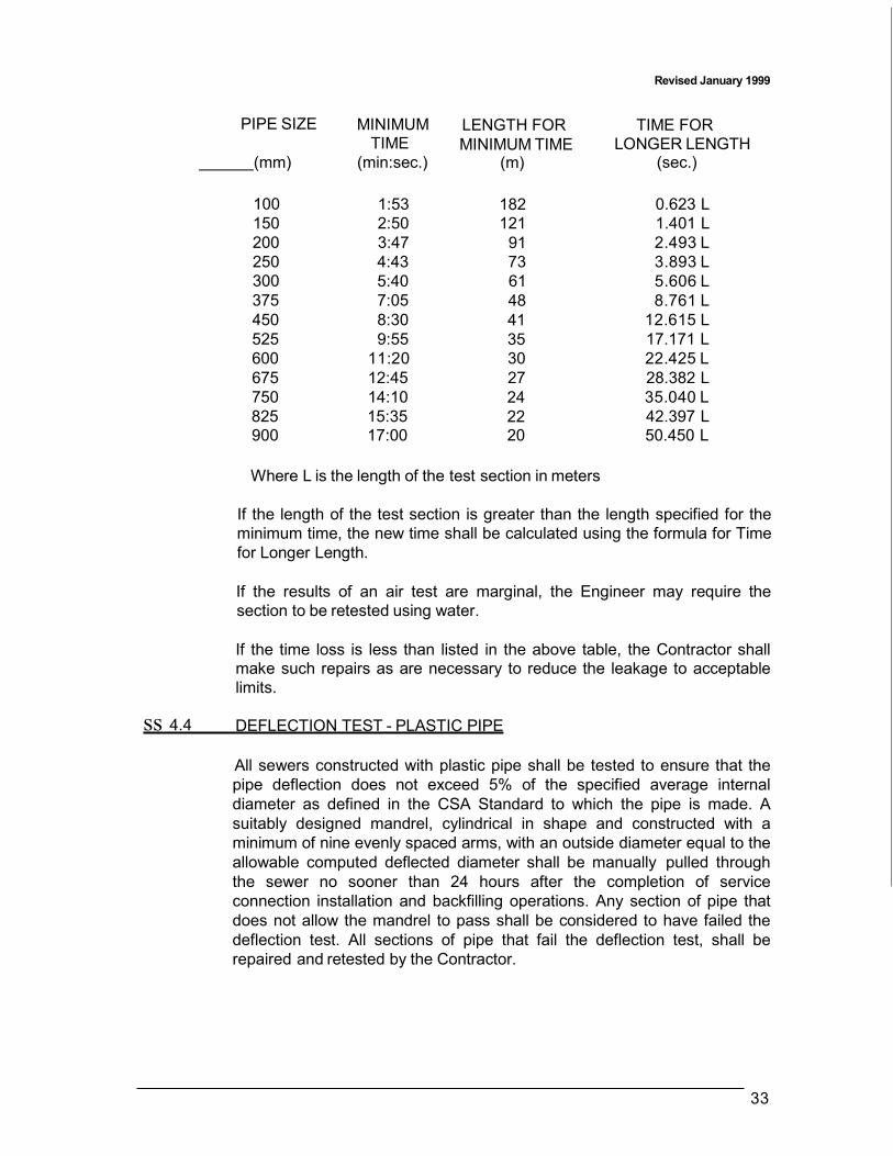
Revised January 1999
33
PIPE SIZE MINIMUM TIME
LENGTH FOR MINIMUM TIME
TIME FOR LONGER LENGTH
(mm) (min:sec.) (m) (sec.)
100
1:53
182
0.623 L 150 2:50 121 1.401 L 200 3:47 91 2.493 L 250 4:43 73 3.893 L 300 5:40 61 5.606 L 375 7:05 48 8.761 L 450 8:30 41 12.615 L 525 9:55 35 17.171 L 600 11:20 30 22.425 L 675 12:45 27 28.382 L 750 14:10 24 35.040 L 825 15:35 22 42.397 L 900 17:00 20 50.450 L
Where L is the length of the test section in meters
If the length of the test section is greater than the length specified for the minimum time, the new time shall be calculated using the formula for Time for Longer Length.
If the results of an air test are marginal, the Engineer may require the section to be retested using water.
If the time loss is less than listed in the above table, the Contractor shall make such repairs as are necessary to reduce the leakage to acceptable limits.
ss 4.4 DEFLECTION TEST - PLASTIC PIPE
All sewers constructed with plastic pipe shall be tested to ensure that the pipe deflection does not exceed 5% of the specified average internal diameter as defined in the CSA Standard to which the pipe is made. A suitably designed mandrel, cylindrical in shape and constructed with a minimum of nine evenly spaced arms, with an outside diameter equal to the allowable computed deflected diameter shall be manually pulled through the sewer no sooner than 24 hours after the completion of service connection installation and backfilling operations. Any section of pipe that does not allow the mandrel to pass shall be considered to have failed the deflection test. All sections of pipe that fail the deflection test, shall be repaired and retested by the Contractor.

Revised January 1999
34
ss 4.5 CAMERA INSPECTION
All sewers and service connections installed are subject to inspection by television/video cameras.
The Engineer may carry out a camera inspection and the Contractor shall provide, at no additional cost, such assistance as the Engineer may require. Provided that no defective work is indicated by such inspections, the whole of the cost for Inspectors, trained operators, equipment rental and materials shall be borne by the Corporation. If, however, defective work is indicated by such inspections, the Contractor shall bear a part of the total cost in the proportion that the number of defective sections of sewer bears to the total number of sections or connections inspected.
ss 4.6 FIELD TESTING OF PIPE GREATER THAN 900MM IN DIAMETER
Pipe greater than 900mm in diameter will not require or be subjected to leakage tests, unless specifically provided for in the Special Provisions.
A visual or camera inspection of the installed pipe shall be made after backfill has been completed. The pipes' acceptance will have as a prerequisite, the repair of any cracks, leaks, and faulty joints in excess of the tolerances as set out in the foregoing specifications.
Revised January 1999
35
ss 5 MEASUREMENT AND PAYMENT
ss 5.1 UNIT OF MEASUREMENT
Measurements shall be in accordance with Canadian Standard Measures.
ss 5.2 MEASUREMENT OF QUANTITIES
Unless otherwise specified, quantities of work shall be determined from measurements or dimensions in horizontal planes. However, linear quantities of pipe, piling, fencing and timber shall be considered as being the true length measured along the longitudinal axis.
Unless otherwise provided in the Special Provisions, volumetric quantities shall be the product of the mean area of vertical or horizontal sections and the intervening horizontal or vertical dimensions.
ss 5.3 OPEN TRENCH INSTALLATIONS
ss 5.3.1 NEW SEWERS, CONNECTIONS OR CONDUITS
Pipe shall be measured along the longitudinal axis from centre to centre of manholes or from the centre of the manhole to the end of the pipe where no manhole is installed under this contract.
Private drain connections to sewers shall be measured from the centre of the main sewer to the upper end of the house connection or lateral. Catchbasin connections shall be measured from the inside face of the catchbasin to the inside face of the sewer or structure to which the connection is being made.
The unit price for pipe in place shall be considered full compensation for all wyes, tees, bends, monolithic catchbasin connections, plugs and specials shown on the plans; the removal of interfering portions of existing sewers. storm drains and improvements; the closing or removing of abandoned conduits and structures; the excavation of the trench; the protection and support of existing structures/utilities; the control of ground and surface waters; the preparation of sub-grade; bedding; placing and joining pipe; backfilling and compacting the trench; disposal of excess materials; permanent resurfacing and all other work necessary to install the pipe complete in place. No extra compensation will be allowed for any additional support such as concrete beams, etc.

36
Revised January 1999
ss 5.3.2 REPLACEMENT OR REPAIR OF EXISTING SEWERS AND
CONNECTIONS
I. Pipe will be measured along the longitudinal axis, end to end of the new structure in place. No deduction will be made for the portion of the new structure at either end that may be enclosed by bells or mechanical joints.
The unit price for the structure in place will be considered full compensation for all joints, gaskets, fittings, field closures, bends, plugs, and grout required to construct a sound and watertight structure; the removal of interfering portions of existing sewers, storm drains and improvements; the closing or removing of abandoned conduits and structures; the excavation of the trench; the protection and support of existing structures/utilities; the control of ground and surface waters; the preparation of sub-grade; bedding; placing and joining pipe; backfilling and compacting the trench; disposal of excess materials; permanent resurfacing; and all other work necessary to install the pipe complete in place. No extra compensation will be allowed for any additional support such as concrete beams, etc.
11. Field taps or tee insertions on existing sewers will be measured on a
per item basis. A unit will consist of all work and material including any portion of the existing sewer that must be removed and replaced in order to install a field connection in accordance with specifications.
The unit price for the structure in place will be considered full compensation for all joints, gaskets, fittings, field closures, bends, plugs, and grout required to construct a sound and watertight structure; the removal of interfering portions of existing sewers, storm drains and improvements; the closing or removing of abandoned conduits and structures; the excavation of the trench; the protection and support of existing structures/utilities; the control of ground and surface waters; the preparation of sub-grade; bedding; placing and joining pipe; backfilling and compacting the trench; disposal of excess materials; permanent resurfacing; and all other work necessary to install the pipe complete in place. No extra compensation will be allowed for any additional support such as concrete beams, etc.
ss 5.4 BORING OR JACKING INSTALLATIONS
The bid prices shall include full compensation for furnishing all labour, materials, tools and equipment and doing all the work involved in constructing the pipe complete in place, including all excavation; furnishing and installing pipe; constructing, supporting and removing pilot tunnels; backfill and replacement of surface or other improvements, and doing whatever else is required to install the sewer as shown on the plans.
Revised January 1999
37
The cost of providing the jacked casing shall be included in the unit price for sewer of drain to be installed within the casing and no separate payment will be made thereof.
ss 5.5 TUNNEL INSTALLATION
The lump sum or unit price for tunnel shall include full compensation for furnishing all labour, materials, tools and equipment and doing all the work involved in constructing the pipe complete in place, including all excavation; dewatering; furnishing and installing pipe; backpacking; maintaining tunnel supports; placing tunnel backfill; grouting; providing access shafts and alignment holes; backfill and replacement of surface or other improvements; and doing whatever else is required to install the tunnel as shown on the plans and specified herein.
ss 5.6 EXCAVATION AND BEDDING
Payment for excavation and bedding shall be included in the unit price for the installation of the pipe as shown on the Contract Drawings and as specified herein. If soft, unstable or unacceptable material is encountered upon which the bedding material or pipe is to be placed, this unsuitable material shall be removed to a depth ordered by the Engineer and replaced with suitable bedding material. Additional bedding as ordered, over and above the amount required by the plans and specifications, will be paid for as provided in the Special Provisions. If the necessity for such additional bedding material has been caused by an act or failure to act on the part of the Contractor or required for the control of water, the Contractor shall bear the cost of the additional excavation and bedding.
ss 5.7 SHEATHING AND SHEET PILING
No payment will be made for sheathing, sheet-piling, braces, shores, stringers or waling strips unless the same are left in place by order of the Engineer and then only for the length and amount actually left in the ground, except that when the length of sheathing or sheet-piling cut off is less than 1.2m, the Contractor will be paid for the entire length driven, the same as if it had been left in the ground.
Notwithstanding the above, if, in the opinion of the Engineer, it is necessary to order sheathing or sheet-piling to be left in place due to the Contractor's failure to initially comply with all the requirements of SS 3.1.6, Sheathing and Shoring, no additional payment shall be made.
ss 5.8 RESTORATION
No additional payment will be made for restoration of curbs, catchbasins, culverts, lawns, driveways, sidewalks, roads, shoulders, fences, hedges, grassed areas, trees, shrubs, or any tangible physical property whether public or private, disturbed as a result of the Contractor's operations in

Revised January 1999
38
constructing the works. The lump sum or unit prices tendered for the work shall be deemed to include restoration to at least equal to the condition prior to construction.
ss 5.9 STRUCTURES
Payment at the contract prices for the various parts comprising structures shall be full compensation for all work required by this specification and shown on the Contract Drawings to provide a complete structure.
Without in any way limiting the foregoing, the work shall include the supply of all materials, all excavations, disposal of all surplus materials, the placing and compaction of granular bedding and backfill, the construction of all cast in place concrete work, the installation of all precast units, the construction of all masonry work, the installation of frames and grates or covers, the installation of up to a maximum of 1.0m of catchbasin lead when connecting to existing catchbasin leads, aluminum ladder rungs and all other miscellaneous metal works, all required surface restoration and all other work necessary to complete the structure in accordance with the contract requirements.
ss 5.9.1 CATCHBASINS
I. Catchbasins will be measured on an item basis and new catchbasins will include the adjustment required to bring them to final grade.
II. Catchbasins with goss gully traps will be measured separately.
111. The price bid per item will include any work required to install subdrains
or similar features including 1m of subdrains in both directions parallel with the road (2m of subdrains per catchbasin).
IV. Catchbasin frames and grates will be measured separately on a per
item basis.
ss 5.9.2 MANHOLES
I. Manholes Bases
Manhole bases can be either precast or cast in place and will include that part of the structure from 0.3m above the highest mainline pipe (not including the rodding eye for drop structures) to the lowest part of the structure. Any special bedding for incoming or outgoing pipes will be considered either part of the unit price payment for the pipe or part of the structure. No extra payment will be made for special bedding. Manhole bases will be measured on a per item basis.

Revise<! January 1999
39
11. Precast Sections
Precast sections will be measured from 0.3m above the highest mainline pipe to the underside of the manhole frame and cover including the adjustment required for final grade. When a precast deck is required for a shallow manhole or for the transition in precast diameter sizes, the deck will be included in the vertical measurement for the larger size precast. In the case of the transition to small precast sections, the measurement of the largest section will end at the visible joint for the small section. In the case of a shallow manhole, the measurement will stop at the bottom of the manhole frame and cover. The vertical measurement will be full compensation for the transition or flat top deck, as well as all required openings or windows. Manhole precast sections will be measured on a vertical unit price basis.
Ill. Chambers
All chambers, precast or constructed in place, will be paid on a lump sum basis and will include all required openings or windows, special bedding, the top and any adjustment to final grade. Where the top serves as a transition to the precast sections, the adjustment to final grade will be part of the vertical measurement for precast sections. This measurement for precast sections will begin at the lowest inside visible joint where the precast meets the transition deck.
IV. Manhole Frames and Covers
Manhole frames and covers will be measured on a per item basis.
ss 5.10 ADJUSTMENTS OF MANHOLES AND CATCHBASINS
Adjustments of manholes and catchbasins will be measured on a per item basis. Payment at the contract price shall be full compensation, regardless of size or type, for the removal and disposal of asphalt or concrete pavement where required, for all necessary excavation, removal and disposal of concrete in structure, for supplying, handling, placing and compaction of materials; and for all other work necessary for the satisfactory completion of the work, except for the removal and replacement of asphalt or concrete curb and gutter, which work shall be paid for at the contract unit price(s) for the items concerned.
The portion of adjustments that is measured (m) as provided in SS 3.5.7, shall be totaled. For each 0.3m of adjustment that is so measured, payment shall be made at the contract price for one item. For that portion of adjustment that is not a complete 0.3m, payment shall be made on a pro-rata basis.
40
ss 5.11 BREAKING INTO MANHOLES AND CATCHBASINS
Revised January 1999
Breaking into manholes and catchbasins will be measured on a per item basis. Payment shall be made at the contract unit price per opening and shall be full compensation for providing the opening and grouting in pipes for all pipes up to 0.5m in diameter. Payment for larger connections shall be on an individual basis and shall be full compensation for providing the opening and grouting in pipes.