reviving a 25 year old fluid bed sewage sludge incinerator · reviving a 25 year old fluid bed...
TRANSCRIPT

Reviving A 25 Year Old Fluid Bed Sewage Sludge Incinerator
Louis T. BarryChavond-Barry Engineering Corp.
400 Route 518, Blawenburg, NJ 08504Milton Grundlock
Gloucester County Utilities Authority
ABSTRACT
In the early 1970's, The Gloucester County Utilities Authority installed a fluidized bedincinerator to burn sewage sludge produced at its sewage treatment facility. At the time ofinstallation, fuel oil prices were below 20¢ per gallon. Capital cost was high, so the installationwas designed without heat recovery. Wet sludge was pumped into the fluidized sand bed alongwith sufficient air and oil to complete the incineration process.
By the mid 1980's sludge production had increased, and the cold windbox model was strugglingto keep up. Preheating of the combustion air was used to improve operation and production rate. Unfortunately, the flat metal plate used for the cold fluidizing air distribution system was limitedto a preheated air temperature of 700/F. A shell and tube air preheater using the hot flue gasfrom the incineration process to heat the combustion air was installed. To avoid fouling, thedirty gas passed downwardly through the tubes while the clean air was passed over the outside ofthe same tubes.
In 1998, even greater capacity was needed from this old incinerator. Replacing the metal airdistribution plate with a refractory dome or a high alloy metal plate was impractical since thewindbox was too short and uninsulated. An air distribution system used for decades in the oilindustry was the solution. The petroleum industry uses a set of parallel perforated pipes tointroduce reactant gas into the fluid bed catalytic crackers. Adapting this technology to the coldwindbox unit was quite successful. The 8'-6" diameter bed section was widened to 9'-0" to allowroom for 8 parallel air pipes. Each pipe was perforated along two lines, 22½/ from the bottomcenter line. The pipes were placed at an elevation such that their air discharge wasapproximately equal to bubble elevation from the original tuyeres. Preheated air is forced downeach pipe-tuyere from a common manifold supported from the incinerator shell.
The original metal tuyeres were cut from the plate and the resulting holes welded closed. Alayer of insulating castable was applied to the top of the metal plate to protect it from the hightemperature of the bed. Several openings were provided to allow air to freely circulate throughthe abandoned windbox below the metal plate. To increase the preheater air temperature, a tallerheat exchanger was installed on the center line of the previous preheater. Minor duct workchanges reconnected the flue gas to the venturi scrubber.
After more than four years of operation, there are no signs of wear of the new pipe-tuyeres. Thepredicted capacity increase and fuel reduction were both achieved. As a means of demonstrating
the improvement, we evaluated the performance based on the sludge from the present dewateringequipment (23% dry solids).
Windbox Temp. Sludge, Dry Tons/Day Oil, Gal/DT 120/F 13.9 81 700 17.6 431200 21.1 14
With the cold and warm windbox limitations, much of the available fluidizing air was needed toburn oil just to maintain the minimum bed temperature. By preheating to a higher temperature,that air is now available for burning sludge dry solids.
The paper presents detailed photographs of the installation and results of performanceevaluations.
KEYWORDS
Sewage Sludge, Biosolids, Fluidized Bed Incinerator, Pipe-Tuyere Retrofit
INTRODUCTION
This 1970's vintage Dorr-Oliver cold wind box fluid bed sewage sludge incinerator wasretrofitted in the 1980's to a 700/F “warm” windbox by the addition of a heat exchanger. Thisupgraded the installation to the now traditional design wherein the hot flue gas leaving thefreeboard passes downward through the tubes and the fluidizing air is preheated by passingthrough the shell side. This change did provide considerable fuel savings. In fact, it cut the fuelby 50%, in addition to the improved throughput. However, the Authority began burning outsidesludge on a toll basis. This resulted in the dewatering becoming less dependably high so theaverage sludge processed fell far short of the target. Once again, with wet sludge too much ofthe air is needed to burn oil for heat diminishing the air available for sludge combustion.
The first solution, from a capital investment standpoint, would be to increase the sludge solidsconcentration. The Authority had just complected the installation of the second FBI whichincluded new belt filter presses. While the solids were a little higher, they still could notdependably meet the needed dryness to reach the desired 17.2 dry tons/day (DT/D). Faced withreplacing the entire incinerator, the decision was made to evaluate means to reduce the need forauxiliary fuel by higher combustion air preheat temperature.
Retrofitting a cold windbox design to a refractory dome hot windbox design poses some majorproblems.
1. The windbox is small and cannot be insulated for 1200/F.2. The metal plate cannot withstand the preheated air temperature. It was designed for cold
air and stretched to the limit operating at a maximum of 700/F.
3. The shell was a straight wall design, making it difficult to install a refractory dometraditionally used for hot windboxes. Furthermore, the dome would take up valuablevolume needed for the windbox.
The solution was staring us right in the face. The Authority’s second fluid bed incinerator wasdesigned with a unique pipe-tuyere air distribution system commonly used for catalytic crackingin the oil refining industry. However, the task of retrofitting an old incinerator with thistechnology was the question. The elements to be considered in designing a hot pipe-tuyere gridinclude:
1. Pipe diameter and wall thickness2. Number of pipes and their spacing3. Hole diameter and number per pipe. Jet penetration was considered to be sure we did not
make a “sand grinder” from the incinerator. 4. Material of construction5. Thermal expansion6. Keeping the sand from flowing back into the pipes. It is inevitable so there must be a
means to get the sand out. 7. How to protect the metal air distribution plate needed for bed support.8. How to handle the problem of a parallel distribution system in a round vessel and have
equal air distribution.
DISCUSSION
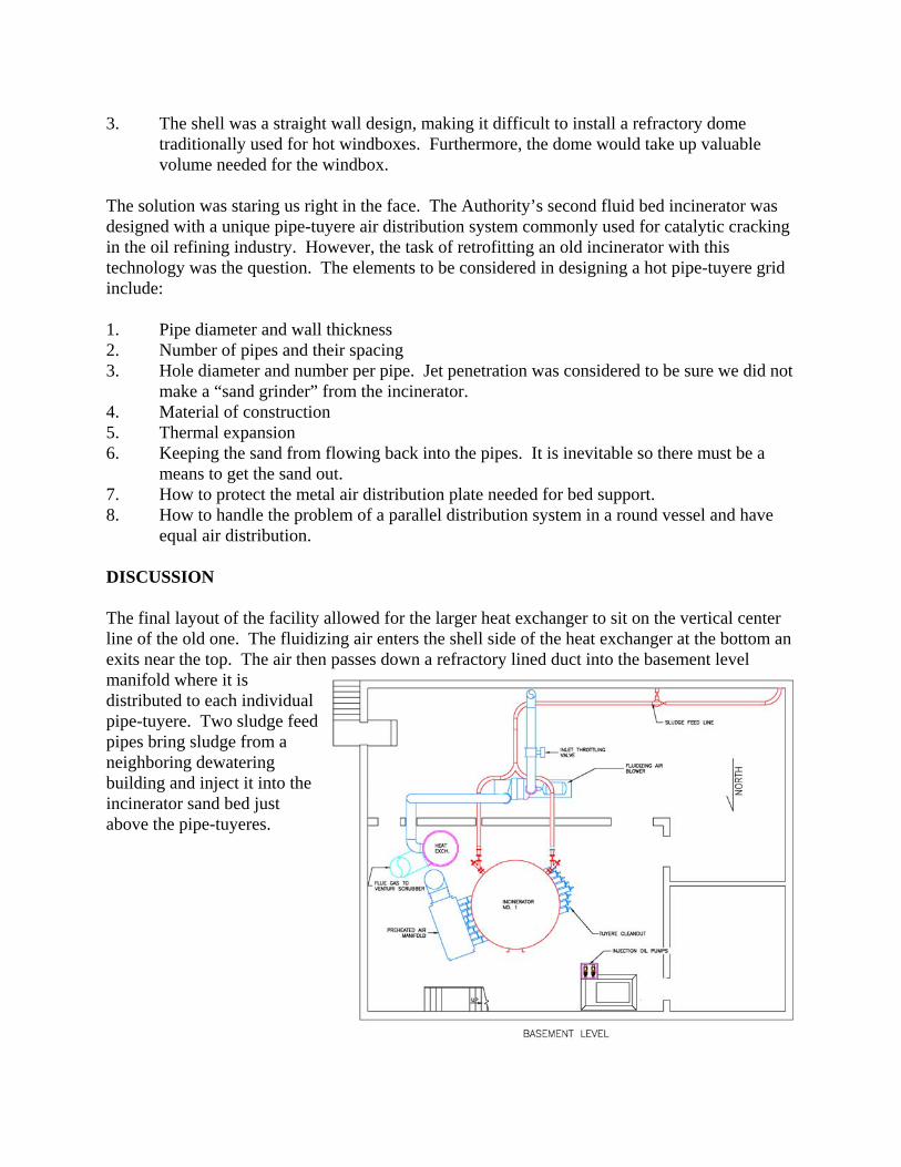
The final layout of the facility allowed for the larger heat exchanger to sit on the vertical centerline of the old one. The fluidizing air enters the shell side of the heat exchanger at the bottom anexits near the top. The air then passes down a refractory lined duct into the basement levelmanifold where it isdistributed to each individualpipe-tuyere. Two sludge feedpipes bring sludge from aneighboring dewateringbuilding and inject it into theincinerator sand bed justabove the pipe-tuyeres.

The Random Section drawingillustrates the incineratormodifications. Starting at thebottom, the existing bottomplate was retained to supportthe bed at rest. The twoopenings into the windboxwere left without covers toallow air circulation. Theinternal insulation on thewindbox walls was removedto allow heat to dissipatefrom the windbox into theroom. After removing theoriginal tuyeres and closingthe resulting holes, a layer ofinsulation and hard castablerefractory was applied on topof the plate. This limits thequantity of heat that reachesthe windbox and, thereby,into the room. There isactually very little heat passing through the insulated support plate. The windbox operates coolenough that there is no noticeable heat into the room.
To allow a little more capacity, the bed diameter was increased form 8'-6" to 9'-0". A largediameter sight glass was added to better observe bed fluidization. The over bed burner wasreplaced with one of larger capacity to serve a dual purpose. Naturally, this is the heat up burnerused to achieve operating temperature from a cold shutdown. However, this burner also servesto assist in maintaining a minimum 1500/F freeboard temperature as required by the stateoperating permit. If the freeboard gas temperature approaches this limit, the freeboard burnerinstantly fires to maintain the minimum required temperature.
Although not shown on this section, the installation is equipped with over bed air. Naturally,this air input is not as efficient as using adequate preheated air, but is used to maintain the
permitted minimum oxygen level on anemergency basis. The oxygen control systemadds over bed air once the measured oxygenapproaches the 3% permit low limit.
The thermal expansion concern is handled byallowing the pipe tuyeres to freely expandaway from the manifold into a nozzle on theopposite side of the incinerator. In the pipe-tuyere photo above, the manifold is on theleft and the pipe-tuyeres are free to expand to

the right through the refractory wall and intothe shell nozzles. This photograph wastaken at the first cold shutdown inSeptember, 2000 after nine months ofoperation. Subsequent inspections haveshown no surface wear.
The concern that the pipe-tuyeres wouldwear away was unfounded. The photographto the left shows the pipe-tuyeres retain theoriginal sand casting surface roughness andthe holes are still sharp edged as seen in themirror. There are two rows of holes,although only one can be seen in the mirror.
The condition of the hard castable refractorycan also be seen in this photograph. Indetermining the relative elevation between
the hot air jetting from the tuyere holes and the refractory protecting the bed support plate, weused the relationship developed by Zenz1 to estimate the distance the jet would penetrate thesand layer. Zenz’ relationship was accurate as evidenced by the lack of damage to the refractory. As a result of these calculations we were able to maintain the same bubble elevation and,therefore, lose no bed volume. For the maximum fluidizing air flow, the selected distancebetween the bubble line and the protective refractory is 7".
The sketch to the left shows the cross section of the pipe-tuyere. For this diameter bed the pipe-tuyeres were 5" OD with a ½" wall thickness. The two rows of holes are rotated 22 1/2/from the bottom of the pipe. This provides apath long enough to prevent the sand fromfiltering backward through the holes byallowing for the natural angle of repose of thesand.
Placing parallel pipes into a round vesselclearly leaves two crescent shaped areaswhere there is less than ideal air flow. Inthese areas, we added nozzles allowing air to
pass from the sides of the two out board pipe-tuyeres. See the illustration to the right fordetails. Care is needed here to assure that the jetblowing at the wall from the side of these tuyeresdoes not hit and erode the wall refractory. Onceagain, Zenz’ relationship proved accurate enough

to protect the wall.
When the fluidizing air blower is turned off suddenly or drops out during a power failure, theuneven settling sand/air mixture causes air and sand back flow in some tuyeres. When the air isresumed some of the sand is expelled through theholes, but some is jammed at the far end of the pipe. Each pipe-tuyere is fitted with a discharge pipe andvalve to remove this deposit. A simple packing glandis used to allow the tuyere to expand and not leak airfrom the vessel. Since the gas is hot and laden withsand, the discharge system includes a water quench tocool and capture the dust.
RESULTS
The initial firing of the modified incinerator wentunexpectedly well. Following a slow careful dry outand heat up using the over bed burner, the sludge wasfinally turned on. After about 30 minutes of doublechecking every reading, we looked to see the feedrate. We were at capacity!
Not all was perfect. As part of the upgrade, the fixedmetal throat venturi scrubber was replaced with a“plumb bob” design variable throat venturi. The high velocity through the old venturicontinuously eroded the bottom cross over section causing shutdowns and excess maintenancecosts. The replacement was specifically installed to eliminate this problem. However, thereplacement eroded through just above the throat inlet area. After several repairs and no advicefrom the manufacturer, it was surmised that the sharp turn into the venturi throat caused theparticulate to bombard one side of the inlet. Ironically, the old venturi, using the same inlet ductdid not experience this problem.
A long radius, refractory lined duct was installed to direct the flow of particulate laden gasstraight into the venturi. This eliminated the problem. The lesson learned is that stream linesinto a venturi are a critical design consideration.
The reasons for the up grade was to increase feed rate and decrease the fuel required per ton ofdry solids fed. Chart 1, below presents the data showing the effect of preheat temperature onthroughput at various sludge solids levels. The data cover the range of 18% to 23%, typical ofthe sludge concentrations that are handled at the Authority. The feed can be increased by 50%by preheating the air to 1200/F, regardless of feed solids content. Note that the freeboardtemperature must be a minimum of 1500/F to meet the state permit requirement. To provide amargin of safety for operations, the is maintained at 1550/F. The higher temperature is used inboth of the following charts.

Chart 1Sludge Feed Rate vs. Dry Solids
10
11
12
13
14
15
16
17
18
19
20
21
22
17% 18% 19% 20% 21% 22% 23% 24%
Sludge Dry Solids, %
Max
imum
Fee
d R
ate,
DT/
D
120 °F Preheat700 °F Preheat1200 °F Preheat
Chart 2, below, shows the effect on specific fuel requirement. As the sludge solids content isincreased, the fuel savings decreases. When feeding 18% solids, the fuel can be reduced by twothirds if the combustion air is preheated to 1200/F. As the sludge gets drier we approachautogenous operation and the calculated fuel savings are greatly increased. At 23% dry solids,the fuel needed with a 1200/F preheat is about 15% of that needed with the cold windbox.
How is it running after four years? The short answer is, Great! Internal examination shows nosign of deterioration of the tuyere pipes or rounding of the tuyere holes. fluidization isunchanged and the capacity, ease of start-up and fuel efficiency remain as designed.

Chart 2Fuel/Dry Ton vs. Dry Solids
0
20
40
60
80
100
120
140
160
17% 18% 19% 20% 21% 22% 23% 24%
Sludge Dry Solids, %
Fuel
, Gal
/Dry
Ton
120 °F Preheat700 °F Preheat1200 °F Preheat
REFERENCES
1Zenz, Frederick A. Fluidization and Fluid-Particle Systems (Vol. II Draft -1989), PEMM-CORP Publications, Garrison, NY