r/evolution 2000 series troubleshooting guide
TRANSCRIPT
2000 Series Troubleshooting Guide
P/N 83-00004287-12Revision AMay 2008

Copyright Protected Material 2002-2008. All rights reserved. R/Evolution and the R/Evolution logo are trademarks of Dot Hill Systems Corp. All other trademarks and registered trademarks are proprietary to their respective owners.The material in this document is for information only and is subject to change without notice. While reasonable efforts have been made in the preparation of this document to assure its accuracy, changes in the product design can be made without reservation and without notification to its users.
3
Contents
Preface . . . . . . . . . . . . . . . . . . . . . . . . . . . . . . . . . . . . . . . . . . . . . . . . . . . . . . . . . . . . 9
1. System Architecture . . . . . . . . . . . . . . . . . . . . . . . . . . . . . . . . . . . . . . . . . . . . . . . . 11
Architecture Overview . . . . . . . . . . . . . . . . . . . . . . . . . . . . . . . . . . . . . . . . . . . . . . . 11
Enclosure Chassis and Midplane . . . . . . . . . . . . . . . . . . . . . . . . . . . . . . . . . . . . . . . 12
Midplane . . . . . . . . . . . . . . . . . . . . . . . . . . . . . . . . . . . . . . . . . . . . . . . . . . . . . . 12
Enclosure ID Display . . . . . . . . . . . . . . . . . . . . . . . . . . . . . . . . . . . . . . . . . . . . 13
Drive Modules . . . . . . . . . . . . . . . . . . . . . . . . . . . . . . . . . . . . . . . . . . . . . . . . . . . . . 14
Disk Drives . . . . . . . . . . . . . . . . . . . . . . . . . . . . . . . . . . . . . . . . . . . . . . . . . . . . 14
Controller Modules . . . . . . . . . . . . . . . . . . . . . . . . . . . . . . . . . . . . . . . . . . . . . . . . . . 15
Drive Expansion Module . . . . . . . . . . . . . . . . . . . . . . . . . . . . . . . . . . . . . . . . . . . . . 15
Power-and-Cooling Modules . . . . . . . . . . . . . . . . . . . . . . . . . . . . . . . . . . . . . . . . . . 15
Power Supply Unit . . . . . . . . . . . . . . . . . . . . . . . . . . . . . . . . . . . . . . . . . . . . . . 16
Cooling Fans . . . . . . . . . . . . . . . . . . . . . . . . . . . . . . . . . . . . . . . . . . . . . . . . . . . 16
Airflow . . . . . . . . . . . . . . . . . . . . . . . . . . . . . . . . . . . . . . . . . . . . . . . . . . . . . . . 17
2. Fault Isolation Methodology . . . . . . . . . . . . . . . . . . . . . . . . . . . . . . . . . . . . . . . . . 19
Gather Fault Information . . . . . . . . . . . . . . . . . . . . . . . . . . . . . . . . . . . . . . . . . . 19
Determine Where the Fault Is Occurring . . . . . . . . . . . . . . . . . . . . . . . . . . . . . . 19
Review the Event Logs . . . . . . . . . . . . . . . . . . . . . . . . . . . . . . . . . . . . . . . . . . . 20
Isolate the Fault . . . . . . . . . . . . . . . . . . . . . . . . . . . . . . . . . . . . . . . . . . . . . . . . . 20
4 R/Evolution 2000 Series Troubleshooting Guide • May 2008
3. Troubleshooting Using System LEDs . . . . . . . . . . . . . . . . . . . . . . . . . . . . . . . . . . 21
LED Names and Locations . . . . . . . . . . . . . . . . . . . . . . . . . . . . . . . . . . . . . . . . . . . 21
Using LEDs to Check System Status . . . . . . . . . . . . . . . . . . . . . . . . . . . . . . . . . . . . 23
Using Enclosure Status LEDs . . . . . . . . . . . . . . . . . . . . . . . . . . . . . . . . . . . . . . 24
Using Drive Module LEDs . . . . . . . . . . . . . . . . . . . . . . . . . . . . . . . . . . . . . . . . 24
Using Controller Module Host Port LEDs . . . . . . . . . . . . . . . . . . . . . . . . . . . . 25
Using the Controller Module Expansion Port LED . . . . . . . . . . . . . . . . . . . . . . 30
Using Ethernet Management Port LEDs . . . . . . . . . . . . . . . . . . . . . . . . . . . . . . 31
Using Controller Module Status LEDs . . . . . . . . . . . . . . . . . . . . . . . . . . . . . . . 32
Using Power-and-Cooling Module LEDs . . . . . . . . . . . . . . . . . . . . . . . . . . . . . 33
Using Expansion Module LEDs . . . . . . . . . . . . . . . . . . . . . . . . . . . . . . . . . . . . 33
4. Troubleshooting Using RAIDar . . . . . . . . . . . . . . . . . . . . . . . . . . . . . . . . . . . . . . 35
Problems Using RAIDar to Access a Storage System . . . . . . . . . . . . . . . . . . . . . . . 36
Determining Storage System Status and Verifying Faults . . . . . . . . . . . . . . . . . . . . 37
Stopping I/O . . . . . . . . . . . . . . . . . . . . . . . . . . . . . . . . . . . . . . . . . . . . . . . . . . . . . . . 38
Clearing Metadata From Leftover Disk Drives . . . . . . . . . . . . . . . . . . . . . . . . . . . . 39
Isolating Faulty Disk Drives . . . . . . . . . . . . . . . . . . . . . . . . . . . . . . . . . . . . . . . . . . 40
Identifying a Faulty Disk Drive . . . . . . . . . . . . . . . . . . . . . . . . . . . . . . . . . . . . 40
Reviewing Disk Drive Error Statistics . . . . . . . . . . . . . . . . . . . . . . . . . . . . . . . 41
Reviewing the Event Logs . . . . . . . . . . . . . . . . . . . . . . . . . . . . . . . . . . . . . . . . 43
Reconstructing a Virtual Disk . . . . . . . . . . . . . . . . . . . . . . . . . . . . . . . . . . . . . . 43
Isolating Data Path Faults . . . . . . . . . . . . . . . . . . . . . . . . . . . . . . . . . . . . . . . . . . . . 45
Isolating Internal Data Path Faults . . . . . . . . . . . . . . . . . . . . . . . . . . . . . . . . . . 45
Isolating External Data Path Faults on an FC Storage System . . . . . . . . . . . . . 51
Isolating External Data Path Faults on an iSCSI Storage System . . . . . . . . . . . 52
Isolating External Data Path Faults on a SAS Storage System . . . . . . . . . . . . . 53
Resetting a Host Channel on an FC Storage System . . . . . . . . . . . . . . . . . . . . . 54
Changing PHY Fault Isolation Settings . . . . . . . . . . . . . . . . . . . . . . . . . . . . . . . . . . 54

Contents 5
Resetting Expander Error Counters . . . . . . . . . . . . . . . . . . . . . . . . . . . . . . . . . . 55
Disabling or Enabling a PHY . . . . . . . . . . . . . . . . . . . . . . . . . . . . . . . . . . . . . . 55
Disabling or Enabling PHY Isolation . . . . . . . . . . . . . . . . . . . . . . . . . . . . . . . . 55
Using Recovery Utilities . . . . . . . . . . . . . . . . . . . . . . . . . . . . . . . . . . . . . . . . . . . . . 56
Removing a Virtual Disk From Quarantine . . . . . . . . . . . . . . . . . . . . . . . . . . . . 56
Trusting a Virtual Disk for Disaster Recovery . . . . . . . . . . . . . . . . . . . . . . . . . . 57
Problems Scheduling Tasks . . . . . . . . . . . . . . . . . . . . . . . . . . . . . . . . . . . . . . . . . . . 59
Affect of Changing the Date and Time . . . . . . . . . . . . . . . . . . . . . . . . . . . . . . . 60
Deleting Tasks . . . . . . . . . . . . . . . . . . . . . . . . . . . . . . . . . . . . . . . . . . . . . . . . . . 60
Errors Associated with Scheduling Tasks . . . . . . . . . . . . . . . . . . . . . . . . . . . . . 60
Selecting Individual Events for Notification . . . . . . . . . . . . . . . . . . . . . . . . . . . . . . 61
Selecting or Clearing All Events for Notification . . . . . . . . . . . . . . . . . . . . . . . . . . . 62
Correcting Enclosure IDs . . . . . . . . . . . . . . . . . . . . . . . . . . . . . . . . . . . . . . . . . . . . . 63
Problems After Power-On or Restart . . . . . . . . . . . . . . . . . . . . . . . . . . . . . . . . . . . . 63
5. Troubleshooting Using Event Logs . . . . . . . . . . . . . . . . . . . . . . . . . . . . . . . . . . . . 65
Event Severities . . . . . . . . . . . . . . . . . . . . . . . . . . . . . . . . . . . . . . . . . . . . . . . . . . . . 65
Viewing the Event Log in RAIDar . . . . . . . . . . . . . . . . . . . . . . . . . . . . . . . . . . . . . . 66
Viewing an Event Log Saved From RAIDar . . . . . . . . . . . . . . . . . . . . . . . . . . . . . . 68
Reviewing Event Logs . . . . . . . . . . . . . . . . . . . . . . . . . . . . . . . . . . . . . . . . . . . . . . . 69
Saving Log Information to a File . . . . . . . . . . . . . . . . . . . . . . . . . . . . . . . . . . . . . . . 70
Configuring the Debug Log . . . . . . . . . . . . . . . . . . . . . . . . . . . . . . . . . . . . . . . . . . . 71
6. Voltage and Temperature Warnings . . . . . . . . . . . . . . . . . . . . . . . . . . . . . . . . . . . 73
Resolving Voltage and Temperature Warnings . . . . . . . . . . . . . . . . . . . . . . . . . . . . 73
Sensor Locations . . . . . . . . . . . . . . . . . . . . . . . . . . . . . . . . . . . . . . . . . . . . . . . . . . . 74
Power Supply Sensors . . . . . . . . . . . . . . . . . . . . . . . . . . . . . . . . . . . . . . . . . . . . 74
6 R/Evolution 2000 Series Troubleshooting Guide • May 2008
Cooling Fan Sensors . . . . . . . . . . . . . . . . . . . . . . . . . . . . . . . . . . . . . . . . . . . . . 74
Temperature Sensors . . . . . . . . . . . . . . . . . . . . . . . . . . . . . . . . . . . . . . . . . . . . . 75
Power-and-Cooling Module Voltage Sensors . . . . . . . . . . . . . . . . . . . . . . . . . . 77
7. Troubleshooting and Replacing FRUs . . . . . . . . . . . . . . . . . . . . . . . . . . . . . . . . . 79
Static Electricity Precautions . . . . . . . . . . . . . . . . . . . . . . . . . . . . . . . . . . . . . . . . . . 80
Identifying Controller or Expansion Module Faults . . . . . . . . . . . . . . . . . . . . . . . . . 80
Removing and Replacing a Controller or Expansion Module . . . . . . . . . . . . . . . . . 82
Saving Configuration Settings . . . . . . . . . . . . . . . . . . . . . . . . . . . . . . . . . . . . . 82
Shutting Down a Controller Module . . . . . . . . . . . . . . . . . . . . . . . . . . . . . . . . . 84
Removing a Controller Module or Expansion Module . . . . . . . . . . . . . . . . . . . 85
Replacing a Controller Module or Expansion Module . . . . . . . . . . . . . . . . . . . 87
Moving a Set of Expansion Modules . . . . . . . . . . . . . . . . . . . . . . . . . . . . . . . . 89
Updating Firmware . . . . . . . . . . . . . . . . . . . . . . . . . . . . . . . . . . . . . . . . . . . . . . . . . 90
Updating Firmware During Controller Replacement . . . . . . . . . . . . . . . . . . . . 90
Updating Firmware Using RAIDar . . . . . . . . . . . . . . . . . . . . . . . . . . . . . . . . . . 91
Identifying SFP Module Faults . . . . . . . . . . . . . . . . . . . . . . . . . . . . . . . . . . . . . . . . 92
Removing and Replacing an SFP Module . . . . . . . . . . . . . . . . . . . . . . . . . . . . . . . . 93
Removing an SFP Module . . . . . . . . . . . . . . . . . . . . . . . . . . . . . . . . . . . . . . . . 93
Installing an SFP Module . . . . . . . . . . . . . . . . . . . . . . . . . . . . . . . . . . . . . . . . . 94
Identifying Cable Faults . . . . . . . . . . . . . . . . . . . . . . . . . . . . . . . . . . . . . . . . . . . . . . 95
Identifying Cable Faults on the Host Side . . . . . . . . . . . . . . . . . . . . . . . . . . . . . 95
Identifying Cable Faults on the Drive Enclosure Side . . . . . . . . . . . . . . . . . . . 95
Disconnecting and Reconnecting SAS Cables . . . . . . . . . . . . . . . . . . . . . . . . . 95
Identifying Drive Module Faults . . . . . . . . . . . . . . . . . . . . . . . . . . . . . . . . . . . . . . . 96
Understanding Disk-Related Errors . . . . . . . . . . . . . . . . . . . . . . . . . . . . . . . . . 96
Disk Drive Errors . . . . . . . . . . . . . . . . . . . . . . . . . . . . . . . . . . . . . . . . . . . . . . . 98
Disk Channel Errors . . . . . . . . . . . . . . . . . . . . . . . . . . . . . . . . . . . . . . . . . . . . . 99
Identifying Faulty Drive Modules . . . . . . . . . . . . . . . . . . . . . . . . . . . . . . . . . . 100
Contents 7
Updating Disk Drive Firmware . . . . . . . . . . . . . . . . . . . . . . . . . . . . . . . . . . . . 101
Removing and Replacing a Drive Module . . . . . . . . . . . . . . . . . . . . . . . . . . . . . . . 104
Replacing a Drive Module When the Virtual Disk Is Rebuilding . . . . . . . . . . 104
Identifying the Location of a Faulty Drive Module . . . . . . . . . . . . . . . . . . . . . 105
Removing a Drive Module . . . . . . . . . . . . . . . . . . . . . . . . . . . . . . . . . . . . . . . 106
Installing a Drive Module . . . . . . . . . . . . . . . . . . . . . . . . . . . . . . . . . . . . . . . . 107
Verify That the Correct Power-On Sequence Was Performed . . . . . . . . . . . . . 109
Installing an Air Management Module . . . . . . . . . . . . . . . . . . . . . . . . . . . . . . 110
Identifying Virtual Disk Faults . . . . . . . . . . . . . . . . . . . . . . . . . . . . . . . . . . . . . . . . 110
Clearing Metadata From a Disk Drive . . . . . . . . . . . . . . . . . . . . . . . . . . . . . . . 112
Identifying Power-and-Cooling Module Faults . . . . . . . . . . . . . . . . . . . . . . . . . . . 112
Removing and Replacing a Power-and-Cooling Module . . . . . . . . . . . . . . . . . . . . 114
Removing a Power-and-Cooling Module . . . . . . . . . . . . . . . . . . . . . . . . . . . . 114
Installing a Power-and-Cooling Module . . . . . . . . . . . . . . . . . . . . . . . . . . . . . 115
Replacing an Enclosure . . . . . . . . . . . . . . . . . . . . . . . . . . . . . . . . . . . . . . . . . . . . . 116
A. Troubleshooting Using the CLI . . . . . . . . . . . . . . . . . . . . . . . . . . . . . . . . . . . . . . 117
Viewing Command Help . . . . . . . . . . . . . . . . . . . . . . . . . . . . . . . . . . . . . . . . . . . . 118
clear cache . . . . . . . . . . . . . . . . . . . . . . . . . . . . . . . . . . . . . . . . . . . . . . . . . . . . . . . 118
clear expander-status . . . . . . . . . . . . . . . . . . . . . . . . . . . . . . . . . . . . . . . . . . . . . . . 118
ping . . . . . . . . . . . . . . . . . . . . . . . . . . . . . . . . . . . . . . . . . . . . . . . . . . . . . . . . . . . . 119
rescan . . . . . . . . . . . . . . . . . . . . . . . . . . . . . . . . . . . . . . . . . . . . . . . . . . . . . . . . . . . 119
reset host-channel-link . . . . . . . . . . . . . . . . . . . . . . . . . . . . . . . . . . . . . . . . . . . . . . 119
restart . . . . . . . . . . . . . . . . . . . . . . . . . . . . . . . . . . . . . . . . . . . . . . . . . . . . . . . . . . . 119
restore defaults . . . . . . . . . . . . . . . . . . . . . . . . . . . . . . . . . . . . . . . . . . . . . . . . . . . . 120
set debug-log-parameters . . . . . . . . . . . . . . . . . . . . . . . . . . . . . . . . . . . . . . . . . . . . 120
set expander-fault-isolation . . . . . . . . . . . . . . . . . . . . . . . . . . . . . . . . . . . . . . . . . . 121
set expander-phy . . . . . . . . . . . . . . . . . . . . . . . . . . . . . . . . . . . . . . . . . . . . . . . . . . 121
set led . . . . . . . . . . . . . . . . . . . . . . . . . . . . . . . . . . . . . . . . . . . . . . . . . . . . . . . . . . . 121
8 R/Evolution 2000 Series Troubleshooting Guide • May 2008
set protocols . . . . . . . . . . . . . . . . . . . . . . . . . . . . . . . . . . . . . . . . . . . . . . . . . . . . . . 121
show debug-log . . . . . . . . . . . . . . . . . . . . . . . . . . . . . . . . . . . . . . . . . . . . . . . . . . . 122
show debug-log-parameters . . . . . . . . . . . . . . . . . . . . . . . . . . . . . . . . . . . . . . . . . . 122
show enclosure-status . . . . . . . . . . . . . . . . . . . . . . . . . . . . . . . . . . . . . . . . . . . . . . 122
show events . . . . . . . . . . . . . . . . . . . . . . . . . . . . . . . . . . . . . . . . . . . . . . . . . . . . . . 123
show expander-status . . . . . . . . . . . . . . . . . . . . . . . . . . . . . . . . . . . . . . . . . . . . . . . 123
show frus . . . . . . . . . . . . . . . . . . . . . . . . . . . . . . . . . . . . . . . . . . . . . . . . . . . . . . . . 123
show protocols . . . . . . . . . . . . . . . . . . . . . . . . . . . . . . . . . . . . . . . . . . . . . . . . . . . . 123
show redundancy-mode . . . . . . . . . . . . . . . . . . . . . . . . . . . . . . . . . . . . . . . . . . . . . 124
trust . . . . . . . . . . . . . . . . . . . . . . . . . . . . . . . . . . . . . . . . . . . . . . . . . . . . . . . . . . . . 124
Problems Scheduling Tasks . . . . . . . . . . . . . . . . . . . . . . . . . . . . . . . . . . . . . . . . . . 125
Create the Task . . . . . . . . . . . . . . . . . . . . . . . . . . . . . . . . . . . . . . . . . . . . . . . . 125
Schedule the Task . . . . . . . . . . . . . . . . . . . . . . . . . . . . . . . . . . . . . . . . . . . . . . 125
Errors Associated with Scheduling Tasks . . . . . . . . . . . . . . . . . . . . . . . . . . . . 126
Missing Parameter Data Error . . . . . . . . . . . . . . . . . . . . . . . . . . . . . . . . . . . . . . . . 126
Index . . . . . . . . . . . . . . . . . . . . . . . . . . . . . . . . . . . . . . . . . . . . . . . . . . . . . . . . . . . 127

9
Preface
This guide describes how to diagnose and troubleshoot a R/Evolution™ storage system, and how to identify, remove, and replace field-replaceable units (FRUs). It also describes critical, warning, and informational events that can occur during system operation. This guide applies to the following enclosures:■ 2730 FC Controller Enclosure■ 2530 SAS Controller Enclosure■ 2330 iSCSI Controller Enclosure■ SAS Expansion Enclosure
This book is written for system administrators and service personnel who are familiar with Fibre Channel (FC), Internet SCSI (iSCSI), and Serial Attached SCSI (SAS) configurations, network administration, and RAID technology.
Before You Read This BookBefore you begin to follow procedures in this book, you must have already installed enclosures and learned of any late-breaking information related to system operation, as described in the getting started guide and release notes.
10 R/Evolution 2000 Series Troubleshooting Guide • May 2008
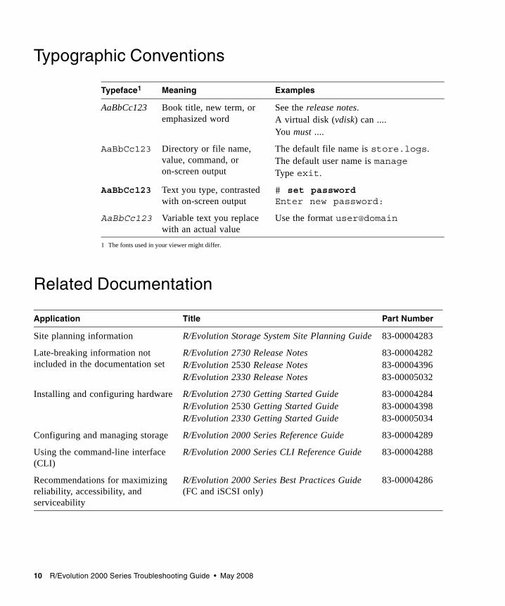
Typographic Conventions
Related Documentation
Typeface1
1 The fonts used in your viewer might differ.
Meaning Examples
AaBbCc123 Book title, new term, or emphasized word
See the release notes.A virtual disk (vdisk) can ....You must ....
AaBbCc123 Directory or file name, value, command, or on-screen output
The default file name is store.logs.The default user name is manageType exit.
AaBbCc123 Text you type, contrasted with on-screen output
# set passwordEnter new password:
AaBbCc123 Variable text you replace with an actual value
Use the format user@domain
Application Title Part Number
Site planning information R/Evolution Storage System Site Planning Guide 83-00004283
Late-breaking information not included in the documentation set
R/Evolution 2730 Release NotesR/Evolution 2530 Release NotesR/Evolution 2330 Release Notes
83-0000428283-0000439683-00005032
Installing and configuring hardware R/Evolution 2730 Getting Started GuideR/Evolution 2530 Getting Started GuideR/Evolution 2330 Getting Started Guide
83-0000428483-0000439883-00005034
Configuring and managing storage R/Evolution 2000 Series Reference Guide 83-00004289
Using the command-line interface (CLI)
R/Evolution 2000 Series CLI Reference Guide 83-00004288
Recommendations for maximizing reliability, accessibility, and serviceability
R/Evolution 2000 Series Best Practices Guide(FC and iSCSI only)
83-00004286
11
CHAPTER 1
System Architecture
This chapter describes the R/Evolution™ storage system architecture. Prior to troubleshooting any system, it is important to understand the architecture, including each of the system components, how they relate to each other, and how data passes through the system. Topics covered in this chapter include:■ “Architecture Overview” on page 11■ “Enclosure Chassis and Midplane” on page 12■ “Drive Modules” on page 14■ “Controller Modules” on page 15■ “Drive Expansion Module” on page 15■ “Power-and-Cooling Modules” on page 15
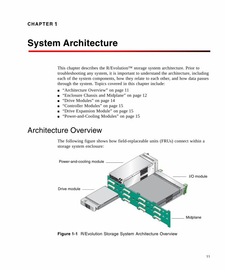
Architecture OverviewThe following figure shows how field-replaceable units (FRUs) connect within a storage system enclosure:
Figure 1-1 R/Evolution Storage System Architecture Overview
Drive module
Power-and-cooling module
Midplane
I/O module
12 R/Evolution 2000 Series Troubleshooting Guide • May 2008
FRUs include:■ Chassis-and-midplane. An enclosure’s 2U metal chassis and its midplane circuit
board comprise a single FRU. All other FRUs connect and interact through the midplane.
■ Drive module. An enclosure can contain 12 SATA or SAS drive modules.■ I/O module. A controller enclosure can contain one or two controller modules; a
drive enclosure can contain one or two expansion modules. Each type of I/O module controls I/O between attached hosts and storage system disk drives.
■ Power-and-cooling modules.
The following sections describe each FRU in more detail.
Note – Do not remove a FRU until the replacement is on-hand. Removing a FRU without a replacement will disrupt the system airflow and cause an over-temperature condition.
Enclosure Chassis and MidplaneAn enclosure’s metal chassis is 2U in height. The front of the enclosure has two rackmount flanges, called ears. The left ear has the enclosure ID display. The right ear has enclosure status LEDs. The chassis also includes the midplane circuit board.
If the chassis or midplane is damaged they are replaced as a unit.
Midplane
The midplane circuit board is the common connection point for all system electronics; all other FRUs plug into this board. Drive modules plug into the front of the midplane. Power-and-cooling modules and I/O modules (controller modules or drive modules) plug into the back of the midplane.
Chapter 1 System Architecture 13
Enclosure ID Display
The enclosure ID (EID) display provides a visual single-digit identifier for each enclosure in a storage system. The EID display is located on the left ear, as viewed from the front of the chassis.
For a storage system that includes a controller module, EID values are set by the RAID controller. For drive enclosures that are attached to a host for use as JBODs (just a bunch of disks), EID values are set by the host.■ When drive enclosures are attached to a controller enclosure
■ The controller enclosure’s EID is zero.■ A drive enclosure’s EID is nonzero. The EID is 1 for the first drive enclosure,
and the EID is incremented for each subsequent enclosure.■ EIDs are persistent, so will not change during simple reconfigurations. ■ EIDs can be used to correlate physical enclosures with logical views of the
storage system provided by system interfaces such as RAIDar.■ When drive enclosures are attached to a host
■ A drive enclosure’s EID can be zero or nonzero.■ Each drive enclosure in a storage system must have a unique EID. ■ EIDs are persistent, so will not change during simple reconfigurations. ■ EIDs can be used to correlate physical enclosures with logical views of the
storage system provided by system interfaces.
When installing a system with drive enclosures attached, the enclosure IDs might not agree with the physical cabling order. This is because the controller might have been previously attached to some of the same enclosures and it attempts to preserve the previous enclosure IDs, if possible. To correct this, make sure that both controllers are up and perform a rescan using RAIDar (see “Correcting Enclosure IDs” on page 63) or the CLI (see “rescan” on page 119). This will reorder the enclosures, but can take up to two minutes for the IDs to be corrected.
EIDs are managed by SES functions of the Expander Controller in each controller module and expansion module.
For information about how EIDs are affected when expansion modules are moved, see “Moving a Set of Expansion Modules” on page 89.

14 R/Evolution 2000 Series Troubleshooting Guide • May 2008
Drive ModulesThe drive module has a front bezel with a latch that is used to insert or remove the drive module. When any component of a drive module fails, the entire module is replaced. Each drive module is inserted into a drive slot (or bay) in an enclosure. The following figure shows the numbering of drive slots in an enclosure.
Figure 1-2 Drive Slot Numbers
A drive is identified by the numbers of the enclosure and slot that the drive is in. For example, the last drive in the controller enclosure is identified as 0.11 (EID 0, slot 11). Drive modules are slot-independent, that is, the drives can be moved to any slot with the power off. Once power is applied, the RAID controllers use the metadata held on each disk to locate each member of a virtual disk.
Disk Drives
Each RAID controller has single-port access from the local SAS expander to internal and drive enclosure drives. Alternate path, dual-port access to all internal drives is accomplished through the expander inter-controller wide lane connection. Dual-port access assumes the presence of both controller modules. In a failed over configuration, where the partner controller module is down or removed, only single-port access to the drives exists.
The storage system can include either or both SAS or SATA II drives. A drive can be interchanged with a qualified equivalent drive. In addition, each enclosure can be populated with disks of various capacities. To ensure the full use of a disk’s capacity, construct all virtual disks with disks of the same capacity.
Chapter 1 System Architecture 15
Controller ModulesA controller module is a FRU that contains two connected circuit boards: a RAID I/O module and a host interface module (HIM).
The RAID I/O module is a hot-pluggable board that mates with the enclosure midplane and provides all RAID controller functions and SAS/SATA disk channels. The HIM provides the host-side interface and contains dual-port, host target channels for connection to host systems. The 2730 has a Fibre Channel HIM that supports 2- or 4-Gbit/sec link speed. The 2330 has an iSCSI HIM that supports 1-Gbit/sec link speed. The 2530 has a SAS HIM that supports 4-lane 3-Gbps host speeds.
The controller module contains three processing subsystems: the Storage Controller, the Management Controller, and the Expander Controller.
Note – When a fault occurs in a controller module processor or a bus fault occurs that is related to the controller module, the entire controller module FRU is replaced.
Drive Expansion ModuleExpansion module architecture is a simplified version of controller module architecture. Like a controller module, an expansion module has an Expander Controller and uses the SAS protocol. Each module has a SAS “In” port and a SAS “Out” port, which enables up to four 2130s to be connected together, and to a host system. When a fault occurs in the Expander Controller or a bus fault occurs that is related to the expansion module, the entire module is replaced.
For information about supported configurations for connecting enclosures to each other and to hosts, see the appropriate getting started guide.
Power-and-Cooling ModulesEach enclosure contains two power-and-cooling modules. A power-and-cooling module is a FRU that includes a power supply unit and two cooling fans. If a power supply fault or fan fault occurs, the entire module is replaced.
16 R/Evolution 2000 Series Troubleshooting Guide • May 2008
Power Supply Unit
Each 750-Watt, AC power supply unit (PSU) is auto-sensing and runs in a load-balanced configuration to ensure that the load is distributed evenly across both power supplies.
Cooling Fans
The cooling fans are integrated into each of the power-and-cooling module FRUs. Each module contains two fans mounted in tandem (series). The fans are powered from the +12V common rail so that a single failed power supply still enables all fans to continue to operate.
The fans cannot be accidentally removed as they are part of the power-and-cooling module. Removing this module requires the disengagement of a captive panel fastener and the operation of an ejector lever to remove it from the chassis.
Should one fan fail in either module, the system continues to operate indefinitely. In addition, the fan system enables the airflow pattern to remain unchanged and there is no pressure leak through the failed fan since there are always two fans in tandem, and they are sealed to each other through a calibrated cavity. Should a power-and-cooling module be turned off or unplugged, the fans inside the module continue to operate at normal capacity. This is accomplished by powering each fan from a power bus on the midplane.
The fans’ variable speed is controlled by the controller modules through an I2C interface. The fans also provide tachometer speed information through the I2C interface. Speed control is accomplished through the use of speed commands issued from the controller module. The controller module has one temperature sensor at the inlet port of the controller to sense the exhaust air temperature from the disk drives. Should the controller module sense a rise in temperature, it can increase fan speed to keep the disk drive temperatures within limits.
Balanced cooling for all of the drives is accomplished through the use of two mechanisms.■ Tuned port apertures in the midplane placed behind each drive carrier slot■ The use of a cavity behind the entire surface of the midplane (side-to-side and
top-to-bottom) that acts as an air pressure equalization chamber. This chamber is commonly evacuated by all of the fans.
In this way the amount of mass flow through each drive slot is controlled to be the same slot to slot.
Chapter 1 System Architecture 17
Airflow is controlled and optimized over the power supply by using the power supply chassis as the air-duct for the power supply, ensuring that there are no dead air spaces in the power supply core and increasing the velocity flow (LFM) by controlling the cross sectional area that the mass flow travels through.
Airflow is controlled and optimized over the RAID I/O board and HIM in a similar manner. The controller cover is used as an air duct to force air over the entire surface of the controller from front to back, ensuring no dead air spaces, and increasing the velocity flow (LFM) by controlling the cross-sectional area that the mass flow travels through.
Cooling for all hot components is passive. There are no other fans in the system other than the fans contained in the power-and-cooling module.
Airflow
Caution – To allow for correct airflow and cooling, use an air management module for removed FRUs. Do not leave a FRU out of its slot for more than two minutes.
As noted above, an enclosures cooling system includes four fans in a tandem parallel array. These variable speed fans provide low noise and high mass flow rates. Airflow is from front to back. Each drive slot draws ambient air in at the front of the drive, sending air over the drive surfaces and then through tuned apertures in the chassis midplane.
Note that the airflow washes over the top and bottom surface of the disk drive at high mass flow and velocity flow rates, so both sides of the drive are used for cooling. The airflow system uses a cavity in the chassis behind the midplane as an air-pressure equalization chamber to normalize the negative pressure behind each of the disk drive slots. This mechanism together with the tuned apertures in the midplane behind each drive assures an even distribution of airflow and therefore LFM for each drive slot. This even cooling extends the operational envelope of the system by ensuring no “hot” drive bypass.
Further, airflow is “in line” with the top and bottom surfaces of the drive to reduce back-pressure and optimize fan performance. All of the mass flow at room ambient is used for cooling the 12 disk drives. The high velocity flow helps to lower the thermal resistance of the disk drive assembly to ambient temperature. The thermal temperature rise of the disk drive is dependent upon the power consumed by the disk drive, which varies by drive model as well as the level of drive activity.

18 R/Evolution 2000 Series Troubleshooting Guide • May 2008
19
CHAPTER 2
Fault Isolation Methodology
The R/Evolution storage system provides many ways to isolate faults within the system. This chapter presents the basic methodology used to locate faults and the associated FRUs.
The basic fault isolation steps are:■ Gather fault information■ Determine where in the system the fault is occurring■ Review event logs■ If required, isolate the fault to a data path component
Gather Fault Information
When a fault occurs, it is important to gather as much information as possible. Doing so will help you determine the correct action needed to remedy the fault.
Begin by reviewing the reported fault. Is the fault related to an internal data path or an external data path? Is the fault related to a hardware component such as a drive module, controller module, or power-and-cooling module? By isolating the fault to one of the components within the storage system, you will be able to determine the necessary action more rapidly.
Determine Where the Fault Is Occurring
Once you have an understanding of the reported fault, review the enclosure LEDs. The enclosure LEDs are designed to alert users of any system faults and might be what alerted the user to a fault in the first place.
When a fault occurs, the status LEDs on an enclosure’s right ear (see Figure 3-1) illuminate. Check the LEDs on the back of the enclosure to narrow the fault to a FRU, connection, or both. The LEDs also help you identify the location of a FRU reporting a fault.
20 R/Evolution 2000 Series Troubleshooting Guide • May 2008
Use RAIDar to verify any faults found while viewing the LEDs. RAIDar is also a good tool to use in determining where the fault is occurring if the LEDs cannot be viewed due to the location of the system. RAIDar provides you with a visual representation of the system and where the fault is occurring. It can also provide more detailed information about FRUs, data, and faults. For more information about LEDs, see “Troubleshooting Using System LEDs” on page 21.
Review the Event Logs
The event logs record all system events. It is very important to review the logs, not only to identify the fault, but also to search for events that might have caused the fault to occur. For example, a host could lose connectivity to a virtual disk if a user changes channel settings without taking the storage resources assigned to it into consideration. In addition, the type of fault can help you isolate the problem to hardware or software. For more information about event logs, see “Troubleshooting Using Event Logs” on page 65.
Isolate the Fault
Occasionally it might become necessary to isolate a fault. This is particularly true with data paths due to the number of components the data path consists of. For example, if a host-side data error occurs, it could be caused by any of the components in the data path: controller module, SFP, cable, switch, or data host. For more information about isolating faults, see “Troubleshooting Using System LEDs” on page 21.
21
CHAPTER 3
Troubleshooting Using System LEDs
The first step in troubleshooting your storage system is to check the status of its LEDs. System LEDs can help you identify the FRU that is experiencing a fault. This chapter includes the following topics:■ “LED Names and Locations” on page 21■ “Using LEDs to Check System Status” on page 23
LED Names and LocationsThis section identifies the LEDs in each FRU.
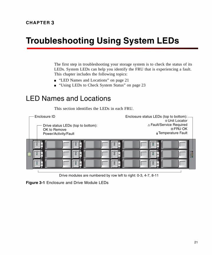
Figure 3-1 Enclosure and Drive Module LEDs
Drive status LEDs (top to bottom):
Enclosure ID Enclosure status LEDs (top to bottom):Unit Locator
Fault/Service RequiredFRU OK
Temperature FaultOK to RemovePower/Activity/Fault
Drive modules are numbered by row left to right: 0-3, 4-7, 8-11
22 R/Evolution 2000 Series Troubleshooting Guide • May 2008
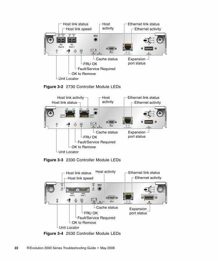
Figure 3-2 2730 Controller Module LEDs
Figure 3-3 2330 Controller Module LEDs
Figure 3-4 2530 Controller Module LEDs
10/100 BASE-T STATUSACTIVITY
DIRTYCLEAN
CACHECLI
MUILINK SPEED LINK SPEED
FCPort 0
FCPort 1
Host link statusHost link speed
Host
ExpansionCache status
Unit LocatorOK to Remove
FRU OKFault/Service Required
activityEthernet link status
Ethernet activity
port status
10/100 BASE-T STATUSACTIVITY
DIRTYCLEAN
CACHECLI
MUILINK ACT
iSCSIPort 0
iSCSIPort 1
LINK ACT
ExpansionCache status
Unit LocatorOK to Remove
FRU OKFault/Service Required
port status
Host link activityHost link status
Hostactivity
Ethernet link statusEthernet activity
ExpansionCache status
Unit LocatorOK to Remove
FRU OKFault/Service Required
port status
Host link status Host activity Ethernet link statusEthernet activity
10/100 BASE-T STATUSACTIVITY
DIRTYCLEAN
CACHECLI
MUI
SASPort 0
SASPort 1
LINK
ACT
LINK
ACT
Host link speed

Chapter 3 Troubleshooting Using System LEDs 23
Figure 3-5 Expansion Module LEDs
Figure 3-6 Power-and-Cooling Module LEDs
Using LEDs to Check System StatusCheck the enclosure status LEDs periodically or after you have received an error notification. If a yellow LED is on, the enclosure has experienced a fault or failure.
More than one of the LEDs might display a fault condition at the same time. For example, if a disk drive failed due to an exceedingly high ambient temperature, both the Temperature Fault LED and the Fault/Service Required LED indicate the fault. This functionality can help you determine the cause of a fault in a FRU.
The following topics describe what to do when an LED indicates a fault condition. For descriptions of all LED statuses, see the getting started guide for your enclosure model.■ “Using Enclosure Status LEDs” on page 24■ “Using Drive Module LEDs” on page 24■ “Using Controller Module Host Port LEDs” on page 25■ “Using the Controller Module Expansion Port LED” on page 30■ “Using Ethernet Management Port LEDs” on page 31■ “Using Controller Module Status LEDs” on page 32■ “Using Power-and-Cooling Module LEDs” on page 33■ “Using Expansion Module LEDs” on page 33
Service
0 0
Unit LocatorOK to Remove
FRU OKFault/Service Required
SAS Out port statusSAS Inport status
AC Power Good
DC Voltage/Fan Fault/Service Required
24 R/Evolution 2000 Series Troubleshooting Guide • May 2008
Using Enclosure Status LEDs
During normal operation, the FRU OK LED is green and the other enclosure-status LEDs are off.
If the FRU OK LED is off, the enclosure is not powered on. If the enclosure should be powered on, verify that its power-and-cooling modules are properly cabled to an active AC power sources and are switched on.
If the Fault/Service Required LED is yellow, an enclosure-level fault occurred and service action is required.
If the Temperature Fault LED is yellow, the enclosure temperature is above threshold.
Using Drive Module LEDs
During normal operation, the OK to Remove LED is off and the Power/Activity/Fault LED is green (steady or blinking).
If the Power/Activity/Fault LED is off, the drive is not powered on. If the drive should be powered on, check that it is fully inserted and latched in place, and that the enclosure is powered on.
If the Power/Activity/Fault LED is steady yellow, either:■ The drive has experienced a fault or has failed.■ The associated virtual disk is critical and no spare is available. This LED is lit for
all drives in the virtual disk. ■ The associated virtual disk is initializing or reconstructing. This LED is lit for all
drives in the virtual disk. No action is needed.
If the OK to Remove LED is blue, the drive module is prepared for removal. However, if the drive has failed and the failure is such that the controller cannot communicate with the drive, this LED is off.
Caution – Do not remove a drive that is rebuilding. Removing a drive may terminate the current operation and cause data loss.
Chapter 3 Troubleshooting Using System LEDs 25
Using Controller Module Host Port LEDs
During normal operation, when a controller module host port is connected to a data host, the port’s host link status LED and host link activity LED are green. For FC, if the link speed is set to 2 Gbit/sec the host link speed LED is off; for 4 Gbit/sec, it is green. If there is I/O activity, the host activity LED blinks green.
If data hosts are having trouble accessing the storage system, check the following.
If the host link status LED is green but the host link speed LED indicates the wrong speed, in RAIDar select Manage > General Config > Host Port Configuration and set the proper link speed.
If a connected port’s host link status LED is off, the link is down. In RAIDar, review the event logs for indicators of a specific fault in a host data path component. If you cannot locate a specific fault or cannot access the event logs, use the procedure for your storage system model to isolate the fault:■ “Isolating a Host-Side Connection Fault on a Fibre Channel Storage System” on
page 25■ “Isolating a Host-Side Connection Fault on an iSCSI Storage System” on page 29
Isolating a Host-Side Connection Fault on a Fibre Channel Storage System
This procedure requires scheduled downtime.
Note – Do not perform more than one step at a time. Changing more than one variable at a time can complicate the troubleshooting process.
1. Halt all I/O to the storage system.
2. Check the host activity LED.If there is activity, halt all applications that access the storage system.
3. Reseat the SFP and FC cable.Is the host link status LED on? ■ Yes – Monitor the status to ensure that there is no intermittent error present. If
the fault occurs again, clean the connections to ensure that a dirty connector is not interfering with the data path.
■ No – Proceed to the next step.
26 R/Evolution 2000 Series Troubleshooting Guide • May 2008
4. Move the SFP and cable to a port with a known good link status.This step isolates the problem to the external data path (SFP, host cable, and host-side devices) or to the controller module port. Is the host link status LED on? ■ Yes – You now know that the SFP, host cable, and host-side devices are
functioning properly. Return the SFP and cable to the original port. If the link status LED remains off, you have isolated the fault to the controller module’s port. Replace the controller module.
■ No – Proceed to the next step.
5. Swap the SFP with the known good one.Is the host link status LED on?■ Yes – You have isolated the fault to the SFP. Replace the SFP.■ No – Proceed to the next step.
6. Re-insert the original SFP and swap the cable with a known good one.Is the host link status LED on?■ Yes – You have isolated the fault to the cable. Replace the cable.■ No – Proceed to the next step.
7. Replace the HBA with a known good HBA, or move the host side cable and SFP to a known good HBA.Is the host link status LED on?■ Yes – You have isolated the fault to the HBA. Replace the HBA.■ No – It is likely that the controller module needs to be replaced.
8. Move the cable and SFP back to its original port.Is the host link status LED on?
■ No – The controller module’s port has failed. Replace the controller module.■ Yes – Monitor the connection for a period of time. It may be an intermittent
problem, which can occur with SFPs, damaged cables, and HBAs.
Chapter 3 Troubleshooting Using System LEDs 27
Isolating a Host-Side Connection Fault on a SAS Storage System
During normal operation, when a controller module host port is connected to a data host, the port’s host link status LED and host link activity LED are green. If there is I/O activity, the host activity LED blinks green. If data hosts are having trouble accessing the storage system, and you cannot locate a specific fault or cannot access the event logs, use the following procedure. This procedure requires scheduled downtime.
Note – Do not perform more than one step at a time. Changing more than one variable at a time can complicate the troubleshooting process.
1. Halt all I/O to the storage system.
2. Check the host activity LED.If there is activity, halt all applications that access the storage system.
3. Reseat the SAS cable.Is the host link status LED on? ■ Yes – Monitor the status to ensure that there is no intermittent error present. If
the fault occurs again, clean the connections to ensure that a dirty connector is not interfering with the data path.
■ No – Proceed to the next step.
4. Move the SAS cable to a port with a known good link status.This step isolates the problem to the external data path (host cable and host-side devices) or to the controller module port. Is the host link status LED on? ■ Yes – You now know that the host cable and host-side devices are functioning
properly. Return the cable to the original port. If the link status LED remains off, you have isolated the fault to the controller module’s port. Replace the controller module.
■ No – Proceed to the next step.
5. Replace the HBA with a known good HBA, or move the host side cable to a known good HBA.
28 R/Evolution 2000 Series Troubleshooting Guide • May 2008
Is the host link status LED on?■ Yes – You have isolated the fault to the HBA. Replace the HBA.■ No – It is likely that the controller module needs to be replaced.
6. Move the cable back to its original port.Is the host link status LED on?
■ No – The controller module’s port has failed. Replace the controller module.■ Yes – Monitor the connection for a period of time. It may be an intermittent
problem, which can occur with damaged cables and HBAs.
Chapter 3 Troubleshooting Using System LEDs 29
Isolating a Host-Side Connection Fault on an iSCSI Storage System
This procedure requires scheduled downtime.
Note – Do not perform more than one step at a time. Changing more than one variable at a time can complicate the troubleshooting process.
1. Halt all I/O to the storage system.
2. Check the host activity LED.If there is activity, halt all applications that access the storage system.
3. Reseat the iSCSI cable.Is the host link status LED on? ■ Yes – Monitor the status to ensure that there is no intermittent error present. If
the fault occurs again, clean the connections to ensure that a dirty connector is not interfering with the data path.
■ No – Proceed to the next step.
4. Move the cable to a port with a known good link status.This step isolates the problem to the external data path (host cable and host-side devices) or to the controller module port.Is the host link status LED on? ■ Yes – You now know that the host cable and host-side devices are functioning
properly. Return the cable to the original port. If the link status LED remains off, you have isolated the fault to the controller module’s port. Replace the controller module.
■ No – Proceed to the next step.
5. Swap the cable with a known good one.Is the host link status LED on?■ Yes – You have isolated the fault to the cable. Replace the cable.■ No – Proceed to the next step.
30 R/Evolution 2000 Series Troubleshooting Guide • May 2008
6. Replace the HBA/NIC with a known good HBA/NIC, or move the host side cable to a known good HBA/NIC.Is the host link status LED on?■ Yes – You have isolated the fault to the HBA/NIC. Replace the HBA/NIC.■ No – It is likely that the controller module needs to be replaced.
7. Move the cable back to its original port.Is the host link status LED on?
■ No – The controller module’s port has failed. Replace the controller module.■ Yes – Monitor the connection for a period of time. It may be an intermittent
problem, which can occur with damaged cables and HBAs/NICs.
Using the Controller Module Expansion Port LED
During normal operation, when a controller module’s expansion port is connected to a drive enclosure, the expansion port status LED is green. If the connected port’s expansion port LED is off, the link is down. If the connected port’s LED is off, the link down. In RAIDar, review the event logs for indicators of a specific fault. If you cannot locate a specific fault or cannot access the event logs, use the following procedure to isolate the fault.
This procedure requires scheduled downtime.
Note – Do not perform more than one step at a time. Changing more than one variable at a time can complicate the troubleshooting process.
1. Halt all I/O to the storage system.
2. Check the host activity LED.If there is activity, halt all applications that access the storage system.
3. Reseat the expansion cable.Is the expansion port status LED on?■ Yes – Monitor the status to ensure there is no intermittent error present. If the
fault occurs again, clean the connections to ensure that a dirty connector is not interfering with the data path.
■ No – Proceed to Step 4.
Chapter 3 Troubleshooting Using System LEDs 31
4. Move the expansion cable to a port on the RAID enclosure with a known good link status.This step isolates the problem to the expansion cable or to the controller module’s expansion port. Is the expansion port status LED on?
■ Yes – You now know that the expansion cable is good. Return cable to the original port. If the expansion port status LED remains off, you have isolated the fault to the controller module’s expansion port. Replace the controller module.
■ No – Proceed to the next step.
5. Move the expansion cable back to the original port on the controller enclosure.
6. Move the expansion cable on the drive enclosure to a known good expansion port on the drive enclosure. Is the expansion port status LED on?■ Yes – You have isolated the problem to the drive enclosure’s port. Replace the
expansion module. ■ No – Proceed to Step 7.
7. Replace the cable with a known good cable, ensuring the cable is attached to the original ports used by the previous cable.Is the host link status LED on?■ Yes – Replace the original cable. The fault has been isolated.■ No – It is likely that the controller module needs to be replaced
Using Ethernet Management Port LEDs
During normal operation, when a controller module’s Ethernet management port is connected, its Ethernet link status LED is green. If there is I/O activity, the host activity LED blinks green.
If a management host is having trouble accessing the storage system, check the following.
If a connected port’s Ethernet link status LED is off, the link is down. Use standard networking troubleshooting procedures to isolate faults on the network.
32 R/Evolution 2000 Series Troubleshooting Guide • May 2008
Using Controller Module Status LEDs
During normal operation, the FRU OK LED is green, the cache status LED can be green or off, and the other controller module status LEDs are off.
If the FRU OK LED is off, either:■ The controller module is not powered on. If it should be powered on, check that
it is fully inserted and latched in place, and that the enclosure is powered on.■ The controller module has failed. Check the event log for specific information
regarding the failure.
If the Fault/Service Required LED is steady yellow, a fault occurred or service action is required.
If the Cache status LED is blinking green, a cache flush or self-refresh is in progress. No action is needed.■ If the LED is blinking evenly, a cache flush is in progress. When a controller
module loses power and write cache is dirty (contains data that has not been written to disk), the super-capacitor pack provides backup power to flush (copy) data from write cache to Compact Flash memory. When cache flush is complete, the cache transitions into self-refresh mode.
■ If the LED is blinking slowly, a cache flush is in progress. In self-refresh mode, if primary power is restored before the backup power is depleted (3–30 minutes depending on various factors), the system boots, finds data preserved in cache, and writes it to disk. This means the system can be operational within 30 seconds, and before the typical host I/O timeout of 60 seconds at which point system failure would cause host-application failure. If primary power is restored after the backup power is depleted, the system boots and restores data to cache from Compact Flash, which can take about 90 seconds.
Note – The cache flush and self-refresh mechanism is an important data protection feature; essentially four copies of user data are preserved: one in each controller's cache and one in each controller's Compact Flash.
If the Fault/Service Required LED is blinking yellow, one of the following errors occurred:■ Hardware-controlled power-up error ■ Cache flush error ■ Cache self-refresh error
If the OK to Remove LED is blue, the controller module is prepared for removal.
Chapter 3 Troubleshooting Using System LEDs 33
Using Power-and-Cooling Module LEDs
During normal operation, the AC Power Good LED is green.
If the AC Power Good LED is off, the module is not receiving adequate power. Verify that the power cord is properly connected and check the power source it is connected to.
If the DC Voltage/Fan Fault/Service Required LED is yellow, the power supply unit or a fan is operating at an unacceptable voltage/RPM level, or has failed. When isolating faults in the power-and-cooling module, remember that the fans in both modules receive power through a common bus on the midplane so if a power supply unit fails, the fans continue to operate normally.
Using Expansion Module LEDs
During normal operation, when the expansion module is connected to a controller module or a host, the SAS In port status LED is green. If the SAS Out port is connected to another expansion module, the SAS Out port status LED is also green. The other LEDs are off.
If a connected port’s status LED is off, the link is down. In RAIDar, review the event logs for indicators of a specific fault in a host data path component.
If the FRU OK LED is off, either:■ The expansion module is not powered on. If it should be powered on, check that
it is fully inserted and latched in place, and that the enclosure is powered on.■ The expansion module has failed. Check the event log for specific information
regarding the failure.
If the Fault/Service Required LED is steady yellow, a fault occurred or service action is required.
If the Fault/Service Required LED is blinking yellow, one of the following errors occurred:■ Hardware-controlled power-up error ■ Cache flush error ■ Cache self-refresh error

34 R/Evolution 2000 Series Troubleshooting Guide • May 2008
35
CHAPTER 4
Troubleshooting Using RAIDar
This chapter describes how to use RAIDar to troubleshoot your storage system and its FRUs. It also describes solutions to problems you might experience when using RAIDar.
Topics covered in this chapter include:■ “Problems Using RAIDar to Access a Storage System” on page 36■ “Determining Storage System Status and Verifying Faults” on page 37■ “Stopping I/O” on page 38■ “Clearing Metadata From Leftover Disk Drives” on page 39■ “Isolating Faulty Disk Drives” on page 40■ “Isolating Data Path Faults” on page 45■ “Changing PHY Fault Isolation Settings” on page 54■ “Using Recovery Utilities” on page 56■ “Problems Scheduling Tasks” on page 59■ “Selecting Individual Events for Notification” on page 61■ “Selecting or Clearing All Events for Notification” on page 62■ “Correcting Enclosure IDs” on page 63■ “Problems After Power-On or Restart” on page 63
Note – You can also use the CLI to troubleshoot your storage system. “Troubleshooting Using the CLI” on page 117 provides information on specific CLI commands that can be used to troubleshoot your system.

36 R/Evolution 2000 Series Troubleshooting Guide • May 2008
Problems Using RAIDar to Access a Storage SystemThe following table lists problems you might encounter when using RAIDar to access a storage system.
Table 4-1 Problems Using RAIDar to Access a Storage System
Problem Solution
You cannot access RAIDar. • Verify that you entered the correct IP address.
• Enter the IP address using the format http://ip-address/index.html
• If the system has two controllers, enter the IP address of the partner controller.
RAIDar pages do not display properly.
• Configure your browser according to the information contained in the reference guide.
• Click Refresh or Reload in your browser to display current data in RAIDar.
• Be sure that someone else is not accessing the system using the CLI. It is possible for someone else to change the system’s configuration using the CLI. The other person’s changes might not display in RAIDar until you refresh the RAIDar page.
• If you are using Internet Explorer, clear the following option: Tools > Internet Options > Accessibility > Ignore Colors Specified On Webpages.
• Prevent RAIDar pages from being cached by disabling web page caching in your browser.
Menu options are not available. User configuration affects the RAIDar menu. For example, diagnostic functions are available only to users with Diagnostic access privileges. See the reference guide for information on user configuration and setting access privileges.
All user profiles have been deleted and you cannot log into RAIDar or the CLI with a remote connection.
1. Use a terminal emulator (such as Microsoft HyperTerminal) to connect to the system.
2. In the emulator, press Enter to display the serial CLI prompt (#). No password is required because the local host is expected to be secure.
3. Use the create user command to create new users. For information about using the command, enter help create user or see the CLI reference guide.
Chapter 4 Troubleshooting Using RAIDar 37
Determining Storage System Status and Verifying Faults
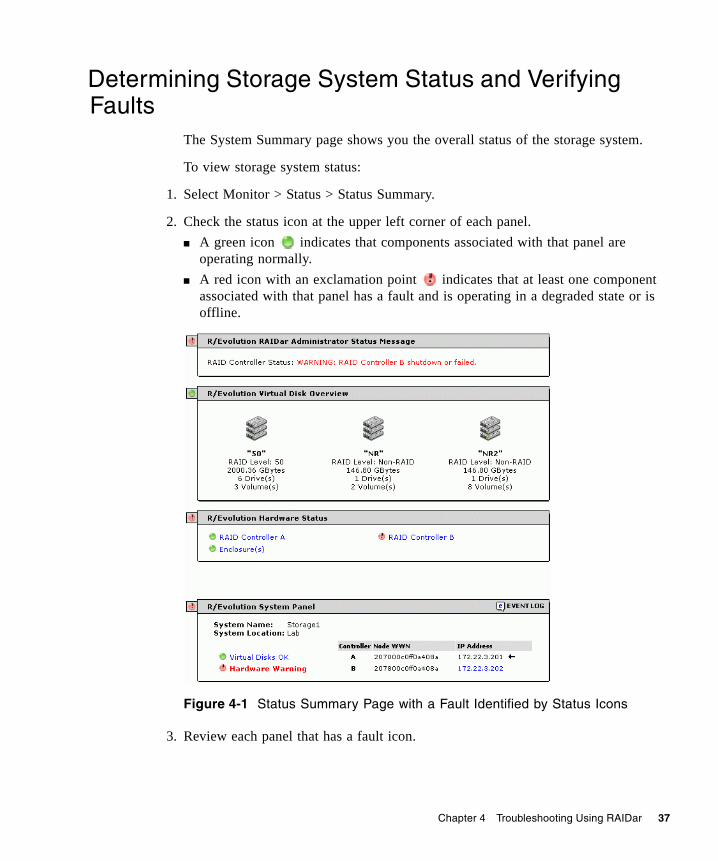
The System Summary page shows you the overall status of the storage system.
To view storage system status:
1. Select Monitor > Status > Status Summary.
2. Check the status icon at the upper left corner of each panel.■ A green icon indicates that components associated with that panel are
operating normally. ■ A red icon with an exclamation point indicates that at least one component
associated with that panel has a fault and is operating in a degraded state or is offline.
Figure 4-1 Status Summary Page with a Fault Identified by Status Icons
3. Review each panel that has a fault icon.
38 R/Evolution 2000 Series Troubleshooting Guide • May 2008
4. Look for red text in the panels.Red text indicates where the fault is occurring. In Figure 4-1 for example, the panels indicate a fault related to controller module B.
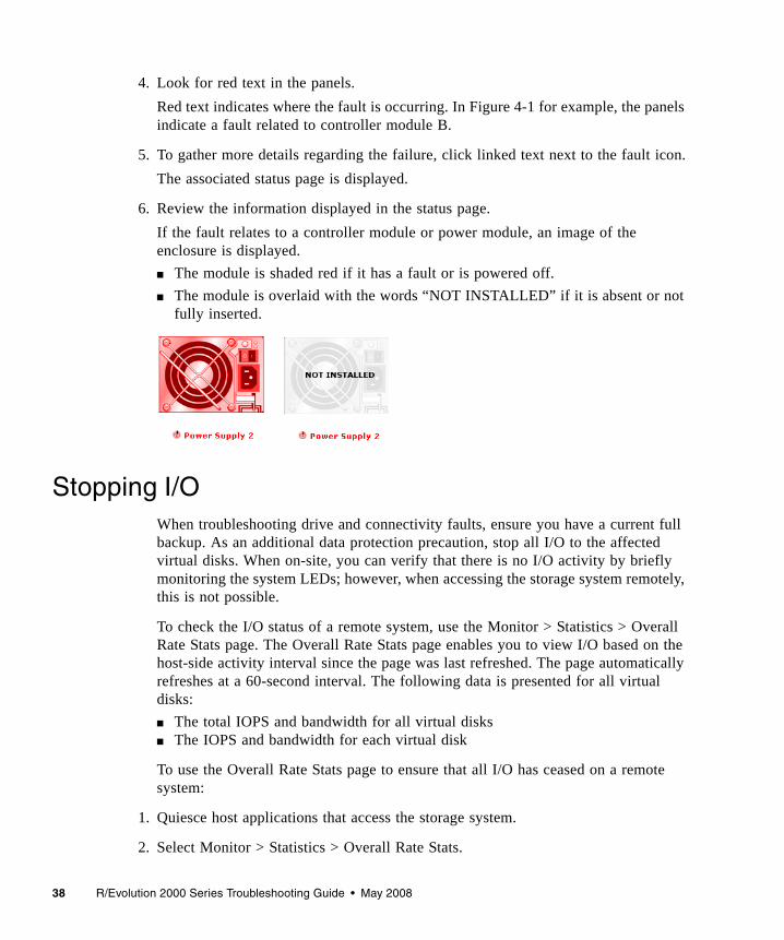
5. To gather more details regarding the failure, click linked text next to the fault icon.The associated status page is displayed.
6. Review the information displayed in the status page.If the fault relates to a controller module or power module, an image of the enclosure is displayed.■ The module is shaded red if it has a fault or is powered off.■ The module is overlaid with the words “NOT INSTALLED” if it is absent or not
fully inserted.
Stopping I/OWhen troubleshooting drive and connectivity faults, ensure you have a current full backup. As an additional data protection precaution, stop all I/O to the affected virtual disks. When on-site, you can verify that there is no I/O activity by briefly monitoring the system LEDs; however, when accessing the storage system remotely, this is not possible.
To check the I/O status of a remote system, use the Monitor > Statistics > Overall Rate Stats page. The Overall Rate Stats page enables you to view I/O based on the host-side activity interval since the page was last refreshed. The page automatically refreshes at a 60-second interval. The following data is presented for all virtual disks:■ The total IOPS and bandwidth for all virtual disks■ The IOPS and bandwidth for each virtual disk
To use the Overall Rate Stats page to ensure that all I/O has ceased on a remote system:
1. Quiesce host applications that access the storage system.
2. Select Monitor > Statistics > Overall Rate Stats.
Chapter 4 Troubleshooting Using RAIDar 39
3. Click your browser’s refresh button to ensure that current data is displayed.
4. In the Host-Generated I/O & Bandwidth Totals for All Virtual Disks panel, verify that both indicators display 0 (no activity).
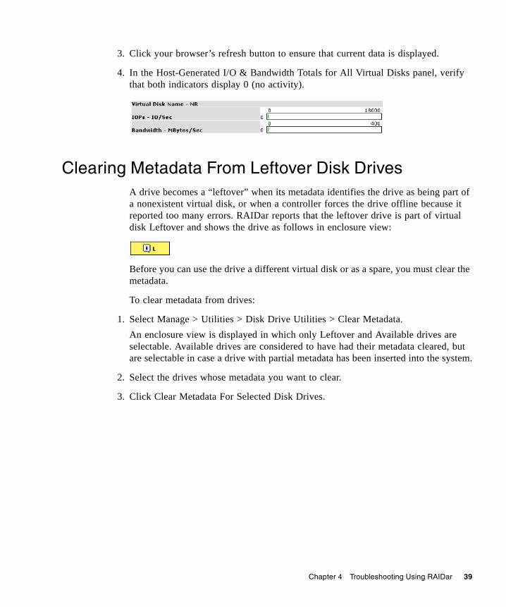
Clearing Metadata From Leftover Disk DrivesA drive becomes a “leftover” when its metadata identifies the drive as being part of a nonexistent virtual disk, or when a controller forces the drive offline because it reported too many errors. RAIDar reports that the leftover drive is part of virtual disk Leftover and shows the drive as follows in enclosure view:
Before you can use the drive a different virtual disk or as a spare, you must clear the metadata.
To clear metadata from drives:
1. Select Manage > Utilities > Disk Drive Utilities > Clear Metadata. An enclosure view is displayed in which only Leftover and Available drives are selectable. Available drives are considered to have had their metadata cleared, but are selectable in case a drive with partial metadata has been inserted into the system.
2. Select the drives whose metadata you want to clear.
3. Click Clear Metadata For Selected Disk Drives.
40 R/Evolution 2000 Series Troubleshooting Guide • May 2008
Isolating Faulty Disk DrivesWhen a drive fault occurs, basic troubleshooting actions are:■ Identify the faulty drive■ Review the drive error statistics■ Review the event log■ Replace the faulty drive■ Reconstruct the associated virtual disk
Identifying a Faulty Disk Drive
The identification of a faulty disk drive involves confirming the drive fault and identifying the physical location of the drive.
To confirm a drive fault, use the basic troubleshooting steps in “Determining Storage System Status and Verifying Faults” on page 37. You can also navigate to the Monitor > Status > Show Notification page and look for any notifications pertaining to a disk drive fault.
When you have confirmed a drive fault, record the drive’s enclosure number and slot number.
To identify the physical location of a faulty drive:
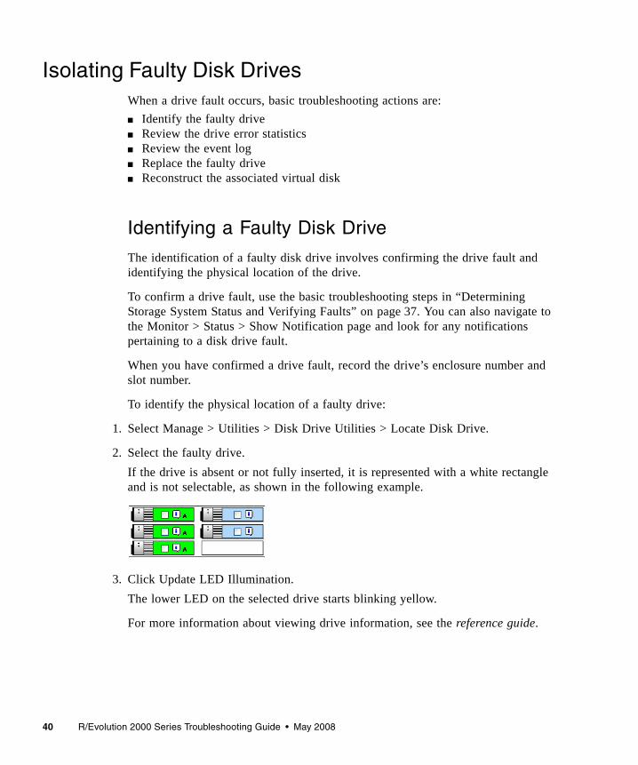
1. Select Manage > Utilities > Disk Drive Utilities > Locate Disk Drive.
2. Select the faulty drive.If the drive is absent or not fully inserted, it is represented with a white rectangle and is not selectable, as shown in the following example.
3. Click Update LED Illumination.The lower LED on the selected drive starts blinking yellow.
For more information about viewing drive information, see the reference guide.
Chapter 4 Troubleshooting Using RAIDar 41
Reviewing Disk Drive Error Statistics
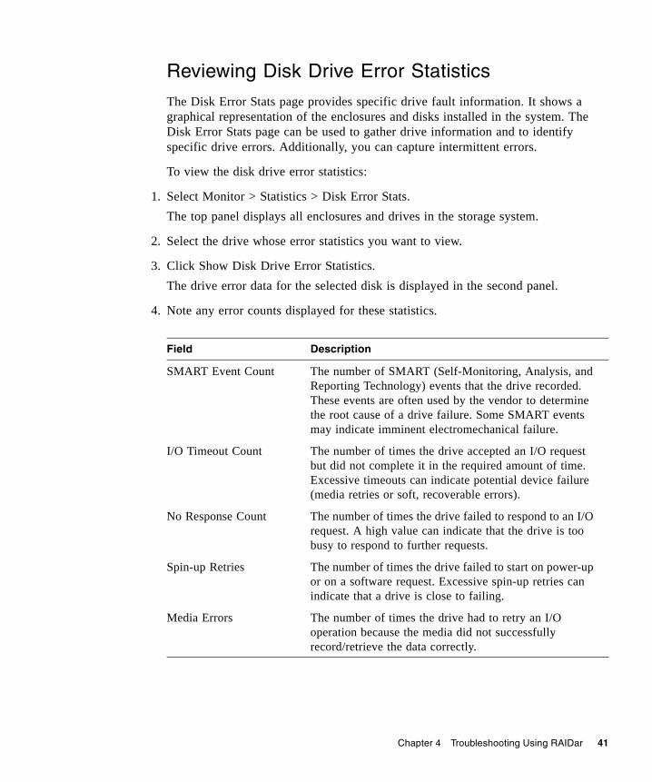
The Disk Error Stats page provides specific drive fault information. It shows a graphical representation of the enclosures and disks installed in the system. The Disk Error Stats page can be used to gather drive information and to identify specific drive errors. Additionally, you can capture intermittent errors.
To view the disk drive error statistics:
1. Select Monitor > Statistics > Disk Error Stats.The top panel displays all enclosures and drives in the storage system.
2. Select the drive whose error statistics you want to view.
3. Click Show Disk Drive Error Statistics.The drive error data for the selected disk is displayed in the second panel.
4. Note any error counts displayed for these statistics.
Field Description
SMART Event Count The number of SMART (Self-Monitoring, Analysis, and Reporting Technology) events that the drive recorded. These events are often used by the vendor to determine the root cause of a drive failure. Some SMART events may indicate imminent electromechanical failure.
I/O Timeout Count The number of times the drive accepted an I/O request but did not complete it in the required amount of time. Excessive timeouts can indicate potential device failure (media retries or soft, recoverable errors).
No Response Count The number of times the drive failed to respond to an I/O request. A high value can indicate that the drive is too busy to respond to further requests.
Spin-up Retries The number of times the drive failed to start on power-up or on a software request. Excessive spin-up retries can indicate that a drive is close to failing.
Media Errors The number of times the drive had to retry an I/O operation because the media did not successfully record/retrieve the data correctly.
42 R/Evolution 2000 Series Troubleshooting Guide • May 2008
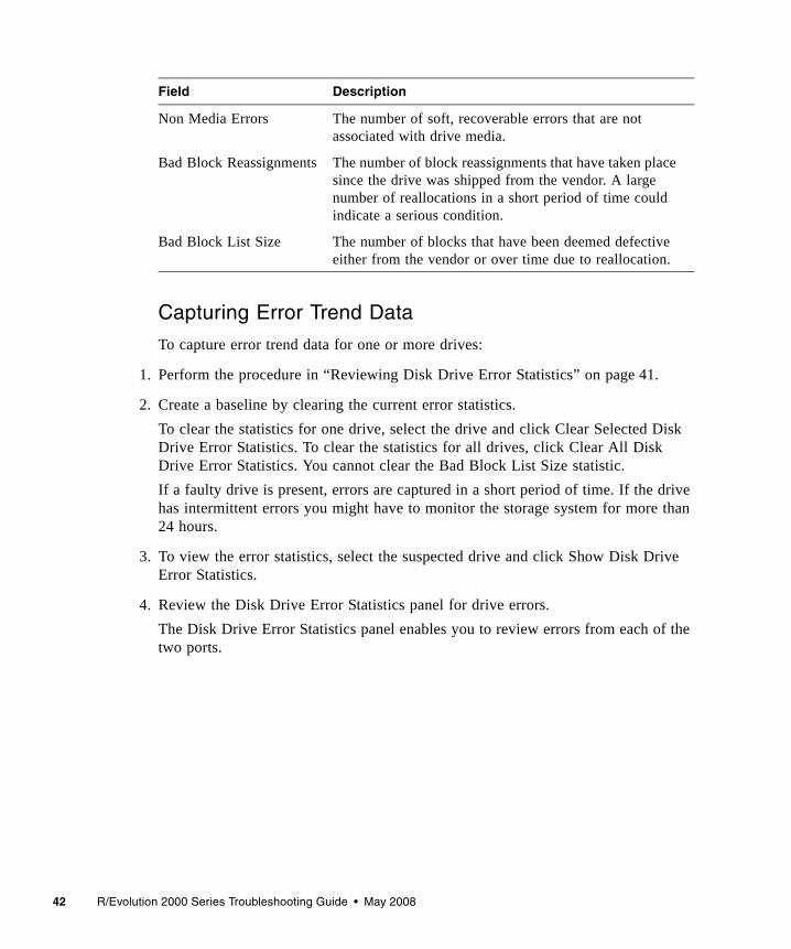
Capturing Error Trend Data
To capture error trend data for one or more drives:
1. Perform the procedure in “Reviewing Disk Drive Error Statistics” on page 41.
2. Create a baseline by clearing the current error statistics.To clear the statistics for one drive, select the drive and click Clear Selected Disk Drive Error Statistics. To clear the statistics for all drives, click Clear All Disk Drive Error Statistics. You cannot clear the Bad Block List Size statistic.If a faulty drive is present, errors are captured in a short period of time. If the drive has intermittent errors you might have to monitor the storage system for more than 24 hours.
3. To view the error statistics, select the suspected drive and click Show Disk Drive Error Statistics.
4. Review the Disk Drive Error Statistics panel for drive errors. The Disk Drive Error Statistics panel enables you to review errors from each of the two ports.
Non Media Errors The number of soft, recoverable errors that are not associated with drive media.
Bad Block Reassignments The number of block reassignments that have taken place since the drive was shipped from the vendor. A large number of reallocations in a short period of time could indicate a serious condition.
Bad Block List Size The number of blocks that have been deemed defective either from the vendor or over time due to reallocation.
Field Description
Chapter 4 Troubleshooting Using RAIDar 43
Reviewing the Event Logs
If all the steps in “Identifying a Faulty Disk Drive” on page 40 and “Reviewing Disk Drive Error Statistics” on page 41 have been performed, you have determined the following:■ A disk drive has encountered a fault ■ The location of the disk drive ■ What the fault is
The next step is to review the event logs to determine if there were any events that led to the fault. If you skip this step, you could replace the faulty drive and then encounter another fault.
To view the event logs from any page, click the icon in the System Panel. See “Troubleshooting Using Event Logs” on page 65 for more information about using event logs.
Reconstructing a Virtual Disk
If one or more drives fail in a redundant virtual disk (RAID 1, 3, 5, 6, 10, or 50) and properly sized spares are available, the storage system automatically uses the spares to reconstruct the virtual disk. Virtual disk reconstruction does not require I/O to be quiesced, so the virtual disk can continue to be used while the Reconstruct utility runs.
A properly sized spare is one whose capacity is equal to or greater than the smallest drive in the virtual disk. If no properly sized spares are available, reconstruction does not start automatically. To start reconstruction manually, replace each failed drive and then do one of the following:■ Add each new drive as a vdisk spare (Manage > Virtual Disk Config > Vdisk
Configuration > Add Vdisk Spares) or a global spare (Manage > Virtual Disk Config > Global Spare Menu > Add Global Spares). Remember that a global spare might be taken by a different critical virtual disk than the one you intended.
■ Enable the Dynamic Spare Configuration option on the Manage > General Config > System Configuration page to use the new drives without designating them as spares.
Reconstructing a RAID-6 virtual disk to a fault-tolerant state requires two properly sized spares to be available.
44 R/Evolution 2000 Series Troubleshooting Guide • May 2008
■ If two drives fail and only one properly sized spare is available, an event indicates that reconstruction is about to start. The Reconstruct utility starts to run, using the spare, but its progress remains at 0% until a second properly sized spare is available.
■ If a drive fails during online initialization, the initialization fails. In order to generate the two sets of parity that RAID 6 requires, the RAID controller fails a second drive in the virtual disk, which changes the virtual disk status to Critical, and then assigns that disk as a spare for the virtual disk. The Reconstruct utility starts to run, using the spare, but its progress remains at 0% until a second properly sized spare is available.
The second available spare can be an existing global spare, another existing spare for the virtual disk, or a replacement drive that you designate as a spare or that is automatically taken when dynamic sparing is enabled.
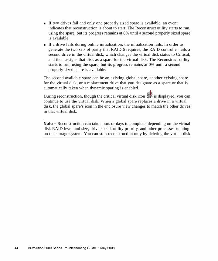
During reconstruction, though the critical virtual disk icon is displayed, you can continue to use the virtual disk. When a global spare replaces a drive in a virtual disk, the global spare’s icon in the enclosure view changes to match the other drives in that virtual disk.
Note – Reconstruction can take hours or days to complete, depending on the virtual disk RAID level and size, drive speed, utility priority, and other processes running on the storage system. You can stop reconstruction only by deleting the virtual disk.

Chapter 4 Troubleshooting Using RAIDar 45
Isolating Data Path FaultsWhen isolating data path faults, you must first isolate the fault to an internal data path or an external data path. This will help to target your troubleshooting efforts.
Internal data paths include the following:■ Controller to disk connectivity■ Controller to controller connectivity■ Controller ingress (incoming signals from drive enclosures)■ Controller egress (outgoing signals to drive enclosures)
External data paths consist of the connections between the storage system and data hosts.
To troubleshoot a data path using RAIDar, do the following:■ Identify the fault as an internal or external data path fault using the steps in
“Determining Storage System Status and Verifying Faults” on page 37■ Gather details about the fault■ Review event logs■ Replace the faulty component
Isolating Internal Data Path Faults
A Physical Layer Interface (PHY) is an interface in a device used to connect to other devices. The term refers to the physical layer of the Open Systems Interconnect (OSI) basic reference model. The physical layer defines all of the electrical and physical specifications for a device.
In a SAS architecture, each physical point-to-point connection is called a lane. Every lane has a PHY at either end. Lanes are sometimes referred to as physical links.
Fault isolation firmware monitors hardware PHYs for problems.
PHYs are tested and verified before shipment as part of the manufacturing and qualification process. But subsequent problems can occur in a PHY because of installation problems such as:■ A bad cable between enclosures■ A controller connector that is damaged as a result of attaching a cable and then
torquing the cable connector until solder joints connecting the controller connector become fatigued or break
46 R/Evolution 2000 Series Troubleshooting Guide • May 2008
Problem PHYs can cause a host or controller to continually rescan drives, which disrupts I/O or causes I/O errors. I/O errors can result in a failed drive, causing a virtual disk to become critical or causing complete loss of a virtual disk if more than one fails.
To avoid these problems, problem PHYs are identified and disabled, if necessary, and status information is transmitted to the controller so that each action can be reported in the event log. Problem PHY identification and status information is reported in RAIDar, but disabled PHYs are only reported through event messages.
Some PHY errors can be expected when powering on an enclosure, when removing or inserting a controller, and when connecting or disconnecting an enclosure. An incompletely connected or disturbed cable might also generate a PHY error. These errors are usually not significant enough to disable a PHY, so the fault isolation firmware analyzes the number of errors and the error rate. If errors for a particular PHY increase at a slow rate, the PHY is usually not disabled. Instead the errors are accumulated and reported.
On the other hand, bad cables connecting enclosures, damaged controller connectors, and other physical damage can cause continual errors, which the fault isolation firmware can often trace to a single problematic PHY. The fault isolation firmware recognizes the large number and rapid rate of these errors and disables this PHY without user intervention. This disabling, sometimes referred to as PHY fencing, eliminates the I/O errors and enables the system to continue operation without suffering performance degradation.
Once the firmware has disabled a PHY, the only way to enable the PHY again is to reset the affected controller or power cycle the enclosure. Before doing so, it may be necessary to replace a defective cable or FRU.
If a PHY becomes disabled, the event log entry helps to determine which enclosure or enclosures and which controller (or controllers) are affected.
RAIDar provides an Expander Status page, which contains an Expander Controller Phy Detail panel. This panel shows information about each PHY in the internal data paths between the Storage Controller, Expander Controller, drives, and expansion ports. By reviewing this page you can quickly locate the internal data path that has a fault.

Chapter 4 Troubleshooting Using RAIDar 47
Checking PHY Status
RAIDar's Expander Status page includes an Expander Controller PHY Detail panel. This panel shows the internal data paths that show the data paths for the Storage Controller, Expander Controller, disks, and expansion ports. Review this page to locate an internal data path that has a fault.
To view expander status information:
1. Select Monitor > Status > Advanced Settings > Expander Status.
2. Select an enclosure.The information is displayed in three panels.The Enclosure Details panel shows the following information about the selected enclosure:■ Name – Name assigned to the enclosure.■ Vendor – Enclosure manufacturer.■ Location – Enclosure location, if set.■ Status – Specifies whether the enclosure is OK or has an error.■ Misc – Enclosure ID, which is 0 for a controller enclosure and increments from 1
for attached drive enclosures. ■ World Wide Name – Enclosure node World Wide Name.■ Model – Enclosure model number.■ Rack:Position – Assigned rack number and position of the enclosure within the
rack, or 0:0 if not set. Position 1 is the top and 16 is the bottom.■ Firmware Version – Version of the EC, which performs SES functions. The Phy Isolation Details panel shows the following settings for each EC:■ Phy Isolation – Shows whether all PHYs in the expander are monitored for faults
and automatically isolated if too many faults are detected. The default is Enabled.■ Monitoring Period – Specifies how often the EC checks each PHY and
determines whether it should be isolated. The default is 100 milliseconds.The Expander Controller Phy Detail panel shows the following information about each PHY in each EC:■ Status – Specifies one of the following:
■ OK – The PHY is healthy.■ Error – The PHY experienced an unrecoverable error condition or received an
unsupported PHY status value.
48 R/Evolution 2000 Series Troubleshooting Guide • May 2008
■ Disabled – The PHY has been disabled by a Diagnostic Manage user or by the system.
■ Non-Critical – The PHY is not coming to a ready state or the PHY at the other end of the cable is disabled.
3. Not Used – The module is not installed.■ Type – Specifies one of the following:
■ Disk – Communicates between the expander and a disk drive.■ Inter-Exp – (Controller module only) Communicates between the expander
and the partner’s expander.■ SC – (Controller module only) Communicates between the expander and the
SC.■ Egress – Communicates between the expander and an expansion port or SAS
Out port.■ Ingress – (Expansion module only) Communicates between an expansion port
and the expander.■ State – Specifies whether the PHY is enabled or disabled.■ ID – Identifies a PHY's logical location within a group based on the PHY type.
Logical IDs are 0–11 for disk PHYs and 0–3 for inter-expander, egress, and ingress PHYs.
■ Details – Pause the cursor over or click the information icon to view a popup with more information. If you click the icon, the information remains shown until the cursor passes over a similar icon.■ Status – The same status value shown in the panel's Status field.■ Physical Phy ID – Identifies a PHY's physical location in the expander.■ Type – The same type value shown in the panel's Type field.■ Phy Change Count – Specifies the number of times the PHY originated a
BROADCAST (CHANGE). A BROADCAST (CHANGE) is sent if doubleword synchronization is lost or at the end of a Link Reset sequence.
■ Code Violation Count – Specifies the number of times the PHY received an unrecognized or unexpected signal.
■ Disparity Error Count – Specifies the number of doublewords containing running disparity errors that have been received by the PHY, not including those received during Link Reset sequences. A running disparity error occurs when positive and negative values in a signal don't alternate.
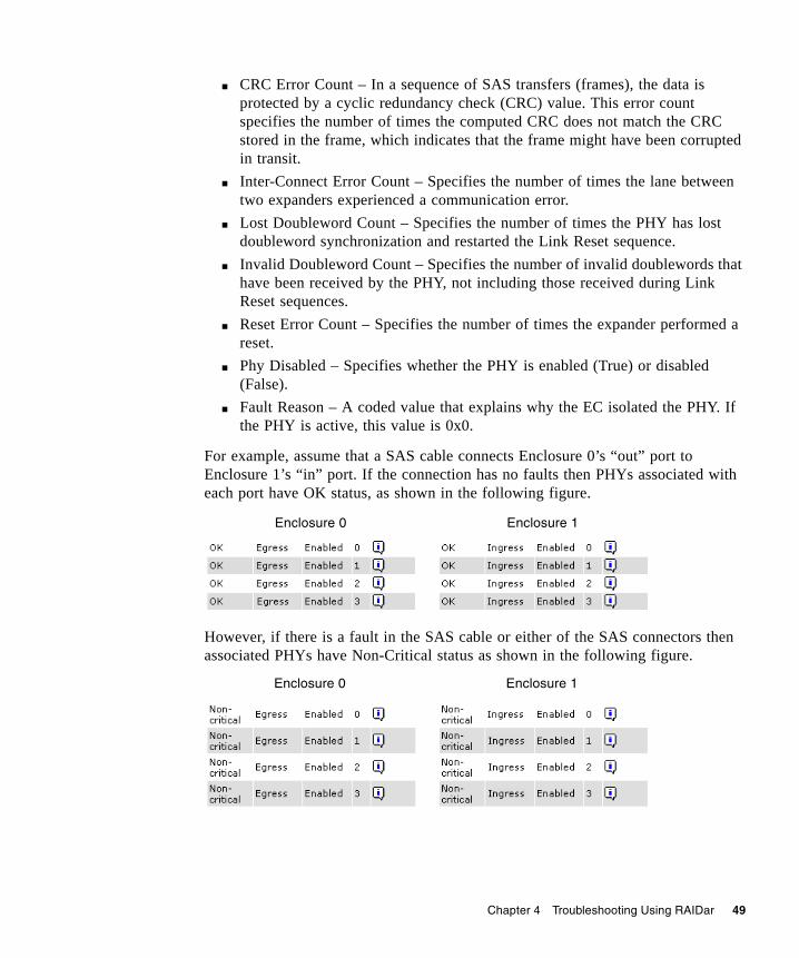
Chapter 4 Troubleshooting Using RAIDar 49
■ CRC Error Count – In a sequence of SAS transfers (frames), the data is protected by a cyclic redundancy check (CRC) value. This error count specifies the number of times the computed CRC does not match the CRC stored in the frame, which indicates that the frame might have been corrupted in transit.
■ Inter-Connect Error Count – Specifies the number of times the lane between two expanders experienced a communication error.
■ Lost Doubleword Count – Specifies the number of times the PHY has lost doubleword synchronization and restarted the Link Reset sequence.
■ Invalid Doubleword Count – Specifies the number of invalid doublewords that have been received by the PHY, not including those received during Link Reset sequences.
■ Reset Error Count – Specifies the number of times the expander performed a reset.
■ Phy Disabled – Specifies whether the PHY is enabled (True) or disabled (False).
■ Fault Reason – A coded value that explains why the EC isolated the PHY. If the PHY is active, this value is 0x0.
For example, assume that a SAS cable connects Enclosure 0’s “out” port to Enclosure 1’s “in” port. If the connection has no faults then PHYs associated with each port have OK status, as shown in the following figure.
However, if there is a fault in the SAS cable or either of the SAS connectors then associated PHYs have Non-Critical status as shown in the following figure.
Enclosure 0 Enclosure 1
Enclosure 0 Enclosure 1
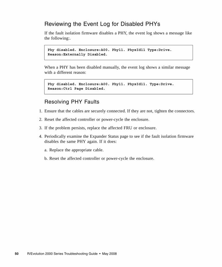
50 R/Evolution 2000 Series Troubleshooting Guide • May 2008
Reviewing the Event Log for Disabled PHYs
If the fault isolation firmware disables a PHY, the event log shows a message like the following:.
When a PHY has been disabled manually, the event log shows a similar message with a different reason:
Resolving PHY Faults
1. Ensure that the cables are securely connected. If they are not, tighten the connectors.
2. Reset the affected controller or power-cycle the enclosure.
3. If the problem persists, replace the affected FRU or enclosure.
4. Periodically examine the Expander Status page to see if the fault isolation firmware disables the same PHY again. If it does:
a. Replace the appropriate cable.
b. Reset the affected controller or power-cycle the enclosure.
Phy disabled. Enclosure:A00. Phy11. PhysId11 Type:Drive. Reason:Externally Disabled.
Phy disabled. Enclosure:A00. Phy11. PhysId11. Type:Drive. Reason:Ctrl Page Disabled.
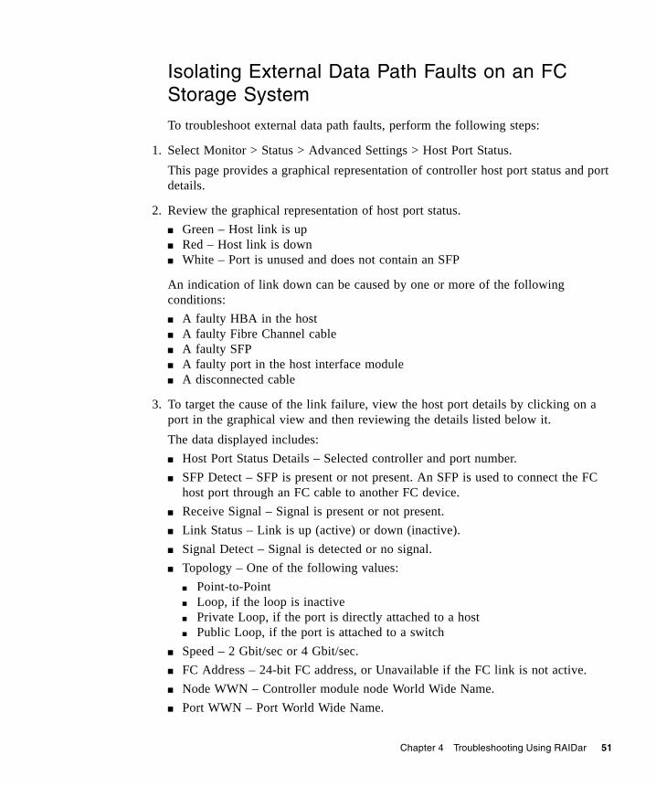
Chapter 4 Troubleshooting Using RAIDar 51
Isolating External Data Path Faults on an FC Storage System
To troubleshoot external data path faults, perform the following steps:
1. Select Monitor > Status > Advanced Settings > Host Port Status. This page provides a graphical representation of controller host port status and port details.
2. Review the graphical representation of host port status.■ Green – Host link is up■ Red – Host link is down■ White – Port is unused and does not contain an SFP
An indication of link down can be caused by one or more of the following conditions:■ A faulty HBA in the host ■ A faulty Fibre Channel cable■ A faulty SFP ■ A faulty port in the host interface module■ A disconnected cable
3. To target the cause of the link failure, view the host port details by clicking on a port in the graphical view and then reviewing the details listed below it.The data displayed includes:■ Host Port Status Details – Selected controller and port number. ■ SFP Detect – SFP is present or not present. An SFP is used to connect the FC
host port through an FC cable to another FC device. ■ Receive Signal – Signal is present or not present. ■ Link Status – Link is up (active) or down (inactive). ■ Signal Detect – Signal is detected or no signal. ■ Topology – One of the following values:
■ Point-to-Point■ Loop, if the loop is inactive■ Private Loop, if the port is directly attached to a host■ Public Loop, if the port is attached to a switch
■ Speed – 2 Gbit/sec or 4 Gbit/sec.■ FC Address – 24-bit FC address, or Unavailable if the FC link is not active.■ Node WWN – Controller module node World Wide Name. ■ Port WWN – Port World Wide Name.
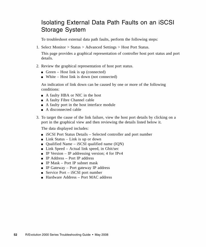
52 R/Evolution 2000 Series Troubleshooting Guide • May 2008
Isolating External Data Path Faults on an iSCSI Storage System
To troubleshoot external data path faults, perform the following steps:
1. Select Monitor > Status > Advanced Settings > Host Port Status. This page provides a graphical representation of controller host port status and port details.
2. Review the graphical representation of host port status.■ Green – Host link is up (connected)■ White – Host link is down (not connected)
An indication of link down can be caused by one or more of the following conditions:■ A faulty HBA or NIC in the host ■ A faulty Fibre Channel cable■ A faulty port in the host interface module■ A disconnected cable
3. To target the cause of the link failure, view the host port details by clicking on a port in the graphical view and then reviewing the details listed below it.The data displayed includes:■ iSCSI Port Status Details – Selected controller and port number■ Link Status – Link is up or down■ Qualified Name – iSCSI qualified name (IQN)■ Link Speed – Actual link speed, in Gbit/sec■ IP Version – IP addressing version; 4 for IPv4■ IP Address – Port IP address■ IP Mask – Port IP subnet mask■ IP Gateway – Port gateway IP address■ Service Port – iSCSI port number■ Hardware Address – Port MAC address
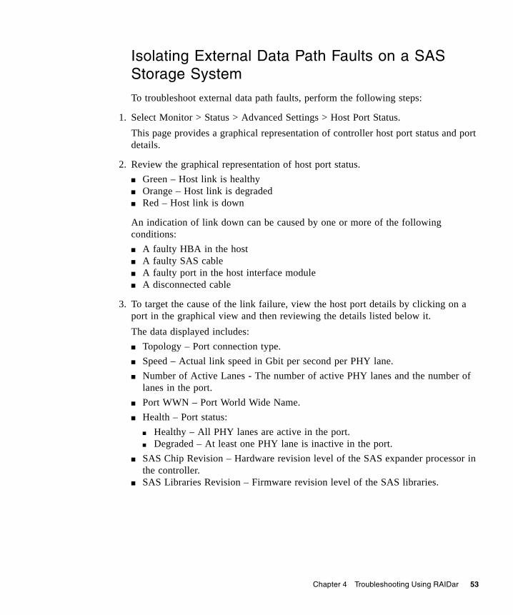
Chapter 4 Troubleshooting Using RAIDar 53
Isolating External Data Path Faults on a SAS Storage System
To troubleshoot external data path faults, perform the following steps:
1. Select Monitor > Status > Advanced Settings > Host Port Status. This page provides a graphical representation of controller host port status and port details.
2. Review the graphical representation of host port status.■ Green – Host link is healthy■ Orange – Host link is degraded■ Red – Host link is down
An indication of link down can be caused by one or more of the following conditions:■ A faulty HBA in the host■ A faulty SAS cable■ A faulty port in the host interface module■ A disconnected cable
3. To target the cause of the link failure, view the host port details by clicking on a port in the graphical view and then reviewing the details listed below it.The data displayed includes:■ Topology – Port connection type.■ Speed – Actual link speed in Gbit per second per PHY lane.■ Number of Active Lanes - The number of active PHY lanes and the number of
lanes in the port.■ Port WWN – Port World Wide Name.■ Health – Port status:
■ Healthy – All PHY lanes are active in the port.■ Degraded – At least one PHY lane is inactive in the port.
■ SAS Chip Revision – Hardware revision level of the SAS expander processor in the controller.
■ SAS Libraries Revision – Firmware revision level of the SAS libraries.
54 R/Evolution 2000 Series Troubleshooting Guide • May 2008
Resetting a Host Channel on an FC Storage System
For a Fibre Channel system using loop topology, you might need to reset a host port (channel) to fix a host connection or configuration problem. As an Advanced Manage user, you can use this command to remotely issue a loop initialization primitive (LIP) on specified controller ports.
To reset a host port:
1. Select Manage > Utilities > Host Utilities > Reset Host Channel.
2. Set the channel and controller options.
3. Click Reset Host Channel.
Changing PHY Fault Isolation SettingsPHY lanes are the physical signal paths used for communication between the SAS expander in each controller module and the drive modules in a system. The Expander Controller in each controller module automatically monitors PHY error (fault) rates and isolates (disables) PHYs that experience too many errors.
The Expander Isolation page is similar to the Expander Status page, but enables you to reset expander error counters, manually disable or enable individual PHYs, and disable or enable PHY fault isolation.
Use of the Expander Status page is described in “Checking PHY Status” on page 47 and in the reference guide.
Chapter 4 Troubleshooting Using RAIDar 55
Resetting Expander Error Counters
If PHYs have errors, you can reset expander error counters and then observe error activity during normal operation. If a PHY continues to accumulate errors you can disable it in the Expander Controller Phy Detail panel.
To reset expander error counters:
● In the Clear Expander Errors panel, click Clear Errors.
Disabling or Enabling a PHY
To disable or enable a PHY:
● In the Expander Controller Phy Detail panel, click the PHY's Disable or Enable button.When you disable a PHY, its button changes to Enable and its Status value changes to DISABLED. When you enable a PHY, its button changes to Disable and its status value changes to OK or another status.
Disabling or Enabling PHY Isolation
You can change an expander’s PHY Isolation setting to enable or disable fault monitoring and isolation for all PHYs in that expander. If Disable is shown, the setting is enabled; if Enable is shown, the setting is disabled. This setting is enabled by default.
To change the PHY isolation setting for expander A or expander B:
● In the Phy Isolation Details panel, click the Phy Isolation field’s Disable or Enable button.When you disable PHY isolation, its button changes to Enable. When you enable PHY isolation, its button changes to Disable.
56 R/Evolution 2000 Series Troubleshooting Guide • May 2008
Using Recovery UtilitiesThis section describes recovering data from a virtual disk that is quarantined or offline (failed).
Removing a Virtual Disk From Quarantine
The quarantine icon indicates that a previously fault-tolerant virtual disk is quarantined because not all of its drives were detected after a restart or rescan. Quarantine isolates the virtual disk from host access, and prevents the storage system from making the virtual disk critical and starting reconstruction when drives are “missing” for these reasons: ■ Slow to spin up after system power-up■ Not properly seated in their slots■ In an powered-off enclosure■ Inserted from a different system and retain old metadata
The virtual disk can be fully recovered if the missing drives can be restored. Make sure that no drives have been inadvertently removed and that no cables have been unplugged. Sometimes not all drives in the virtual disk power up. Check that all enclosures have rebooted after a power failure. If these problems are found and then fixed, the virtual disk recovers and no data is lost.
The quarantined virtual disk’s drives are “write locked,” and the virtual disk is not available to hosts until the virtual disk is removed from quarantine. The system waits indefinitely for the missing drives. If the drives are found, the system automatically removes the virtual disk from quarantine. If the drives are never found because they have been removed or have failed, you must manually remove the virtual disk from quarantine.
If the missing drives cannot be restored (for example, a failed drive), you can remove the virtual disk from quarantine to restore operation in some cases. If you remove from quarantine a virtual disk that is not missing too many drives, its status changes to critical. Then, if spares of the appropriate size are available, reconstruction begins.
Note – After you dequarantine the virtual disk, make sure that a spare drive is available to let the virtual disk reconstruct.
Chapter 4 Troubleshooting Using RAIDar 57
Caution – If the virtual disk does not have enough drives to continue operation, when a dequarantine is done, the virtual disk goes offline and its data cannot be recovered.
To remove a virtual disk from quarantine:
1. Select Manage > Utilities > Recovery Utilities > Vdisk Quarantine.For each virtual disk, the virtual disk panel shows a status icon; the name, RAID level, size, number of disk drives, and number of volumes; and utility status, if any.
2. Select the virtual disk to dequarantine.
3. Click Dequarantine Selected Virtual Disk.
Trusting a Virtual Disk for Disaster Recovery
If a virtual disk appears to be down or offline (not quarantined) and its drives are labeled “Leftover,” use the Trust Virtual Disk function to recover the virtual disk. The Trust Virtual Disk function brings a virtual disk back online by ignoring metadata that indicates the drives might not form a coherent virtual disk. This function can force an offline virtual disk to be critical or fault tolerant, or a critical virtual disk to be fault tolerant. You might need to do this when:■ A drive was removed or was marked as failed in a virtual disk due to
circumstances you have corrected (such as accidentally removing the wrong disk). In this case, one or more drives in a virtual disk can start up more slowly, or might have been powered on after the rest of the drives in the virtual disk. This causes the date and time stamps to differ, which the storage system interprets as a problem. Also see “Removing a Virtual Disk From Quarantine” on page 56.
■ A virtual disk is offline because a drive is failing, you have no data backup, and you want to try to recover the data from the virtual disk. In this case, the Trust Virtual Disk function might work, but only as long as the failing drive continues to operate.
Caution – If used improperly, the Trust Virtual Disk feature can cause unstable operation and data loss. Only use this function for disaster recovery purposes and when advised to do so by a service technician. The virtual disk has no tolerance for any additional failures.
58 R/Evolution 2000 Series Troubleshooting Guide • May 2008
To enable and use Trust Vdisk:
1. Select Manage > Utilities > Recovery Utilities > Enable Trust Vdisk.
2. Select Enabled.
3. Click Enable/Disable Trust Vdisk.The option remains enabled until you trust a virtual disk or restart the storage system.
4. Select Manage > Utilities > Recovery Utilities > Trust Vdisk.
5. Select the virtual disk and click Trust This Vdisk.
6. Back up the data from all the volumes residing on this virtual disk and audit it to make sure that it is intact.
7. Select Manage > Virtual Disk Config > Verify Virtual Disk. While the verify utility is running, any new data written to any of the volumes on the virtual disk is written in a parity-consistent way.
Note – If the virtual disk does not come back online, it might be that too many drives are offline or the virtual disk might have additional failures on the bus or enclosure that Trust Virtual Disk cannot fix.
Chapter 4 Troubleshooting Using RAIDar 59
Problems Scheduling TasksIf your task does not run at the times you specified, check the schedule specifications. It is possible to create conflicting specifications.■ Start time is the first time the task will run.■ If you use the Between option, the starting date/time must be in the Between
range.■ The year must be four digits, between 2006 and 2999.■ Either the Repeat option or the Expires On option will end a schedule.■ Using the Every option with a time value specifies that the task will recur at a
specified time.■ Using the Every option with a date value specifies that the task will recur on the
specified days at either the start time or another specified time.■ The Only On option constrains the period of recurrence.
To debug schedule parameters:
1. Will the task run if you only specify a start time?Schedule your task with only the start time. Remove all other constraints. Review the schedule table. Look at the Next Time to run column. Does it show what you expect? If the task does not run, check how you created the task.
2. Add one more specification. For example, if you want the task to run every day between 1:00 AM and 2:00 AM add the between times. Make sure the start time is between 1:00 AM and 2:00 AM in this example.
3. Continue adding specifications one at a time, verifying that the task runs as scheduled.
Two parameters stop the schedule: expire and count. They can be conflicting without causing an error. If you want a task to run every day until the end of the month, and you put in a count of 10, the task runs a maximum of 10 times. If the expire date is before the 10 times, then the task will only run until the expire date.
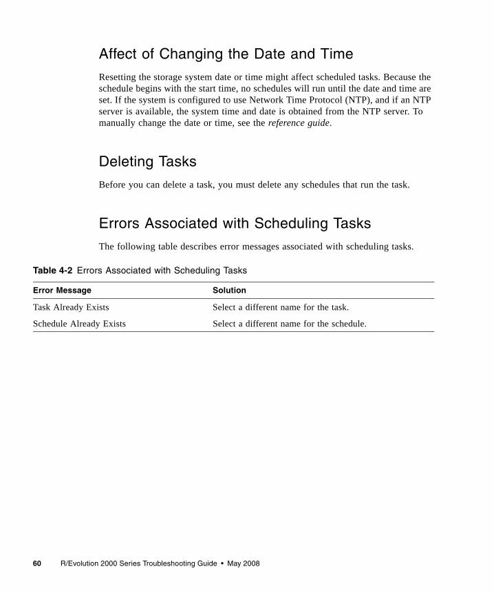
60 R/Evolution 2000 Series Troubleshooting Guide • May 2008
Affect of Changing the Date and Time
Resetting the storage system date or time might affect scheduled tasks. Because the schedule begins with the start time, no schedules will run until the date and time are set. If the system is configured to use Network Time Protocol (NTP), and if an NTP server is available, the system time and date is obtained from the NTP server. To manually change the date or time, see the reference guide.
Deleting Tasks
Before you can delete a task, you must delete any schedules that run the task.
Errors Associated with Scheduling Tasks
The following table describes error messages associated with scheduling tasks.
Table 4-2 Errors Associated with Scheduling Tasks
Error Message Solution
Task Already Exists Select a different name for the task.
Schedule Already Exists Select a different name for the schedule.
Chapter 4 Troubleshooting Using RAIDar 61
Selecting Individual Events for NotificationAs described in the reference guide, you can configure how and under what conditions the storage system alerts you when specific events occur. In addition to selecting event categories, as a Diagnostic Manage user you can select individual events that you want to be notified of.
Note – Selecting many individual events can result in the system sending numerous event notifications. Select the categories and individual events that are most important to you.
Use this method when you want to track or watch for a specific event. You can also use it to receive notification of specific functions being started or completed, such as reconstruction or completion of initialization.
Individual event selections do not override the Notification Enabled or Event Categories settings as explained in the reference guide. If the notification is disabled, the individual event selection is ignored. Similarly, Event Categories settings have higher precedence for enabling events than individual event selection. If the critical event category is selected, all critical events cause a notification regardless of the individual critical event selection. You can select individual events to fine-tune notification either instead of or in addition to selecting event categories. For example, you can select the critical event category to be notified of all critical events, and then select additional individual warning and informational events.
To select events for notification:
1. Select Manage > Event Notification > Select Individual Events.The Critical Events page is displayed.
2. From the Manage menu, display the page for the type of event you want to track:■ Critical Events – Represent serious device status changes that might require
immediate intervention.■ Warning Events – Represent device status changes that might require attention.■ Informational Virtual Disk Events – Represent device status changes related to
virtual disks that usually do not require attention.■ Informational Drive Events – Represent device status changes related to disk
drives that do not require attention.■ Informational Health Events – Represent device status changes related to the
storage system’s health that usually do not require attention.
62 R/Evolution 2000 Series Troubleshooting Guide • May 2008
■ Informational Status Events – Represent device status changes related to the storage system’s status that usually do not require attention.
■ Informational Configuration Events – Represent device status changes related to the storage system’s configuration that usually do not require attention.
■ Informational Miscellaneous Events – Represent device status changes related to informational events that usually do not require attention.
3. Select events by clicking the corresponding check box in the column.
4. For each event you want to be notified of, select a notification method.For a description of each notification method, see the reference guide.
5. Click the change events button.
Selecting or Clearing All Events for NotificationYou can select or clear all individual events for any or all of the notification types.
Selecting all individual events is useful if you want to select many events but not all; set all the events on this page, then go to pages for individual events and clear events you don't want.
Clearing all individual events is useful if you want to clear all the individual event settings so you can set up a new custom configuration.
To select all events:
1. In the Set All Individual Events panel, select the checkbox for each notification type to use.
2. Click Set All Individual Events.
To clear all events:
1. In the Clear All Individual Events panel, select the checkbox for each notification type you don’t want to use.
2. Click Clear All Individual Events.
Chapter 4 Troubleshooting Using RAIDar 63
Correcting Enclosure IDsWhen installing a system with drive enclosures attached, the enclosure IDs might differ from the physical cabling order. This is because the controller might have been previously attached to some of the same enclosures and it attempts to preserve the previous enclosure IDs if possible. To correct this condition, you can perform a rescan.
To rescan, as an Advanced Manage user:
1. Verify that both controllers are up.
2. Select Manage > Utilities > Disk Drive Utilities > Rescan.
In the Rescan For Devices panel, click Rescan.
Problems After Power-On or RestartAfter powering on the storage system or restarting the MC or SC, the processors take about 45 seconds to boot up, and the system takes an additional minute or more to become fully functional and able to process commands from RAIDar or the CLI. The time to become fully functional depends on many factors such as the number of enclosures, the number of disk drives, the number of virtual disks, and the amount of I/O running at the time of the restart. During this time, some RAIDar or CLI commands might fail and some RAIDar pages may not be available. If this occurs, wait a few minutes and try again.

64 R/Evolution 2000 Series Troubleshooting Guide • May 2008
65
CHAPTER 5
Troubleshooting Using Event Logs
Event logs capture reported events from components throughout the storage system. Each event consists of an event code, the date and time the event occurred, which controller reported the event, and a description of what occurred.
This chapter includes the following topics:■ “Event Severities” on page 65■ “Viewing the Event Log in RAIDar” on page 66■ “Viewing an Event Log Saved From RAIDar” on page 68■ “Reviewing Event Logs” on page 69■ “Saving Log Information to a File” on page 70■ “Configuring the Debug Log” on page 71
Event SeveritiesThe storage system generates events having three severity levels:■ Informational – A problem occurred that the system corrected, or a system
change has been made. These events are purely informational; no action required.■ Warning – Something related to the system or to a virtual disk has a problem.
Correct the problem as soon as possible.■ Critical – Something related to the system or to a virtual disk has failed and
requires immediate attention.
There are a number of conditions that trigger warning or critical events and can affect the state of status LEDs. For a list of events, see the reference guide.
66 R/Evolution 2000 Series Troubleshooting Guide • May 2008
Viewing the Event Log in RAIDarSome of the key warning and error events included in the event log during operation include the following:■ Disk detected error ■ Disk channel error ■ Drive down ■ Virtual disk critical ■ Virtual disk offline ■ Temperature warning■ Temperature failure (this leads to a shutdown which is also logged) ■ Voltage warning■ Voltage failure (this leads to a shutdown which is also logged)
The event log stores the most recent events with a time stamp next to them with one-second granularity.
Note – If you are having a problem with the system or a virtual disk, check the event log before calling technical support. Event messages might enable you to resolve the problem.
You can save the event log to a file; see “Saving Log Information to a File” on page 70.
To view the event log:
1. Do one of the following:■ In the System Panel, click the icon.■ In the menu, select Monitor > Status > View Event Log.
The event log page is displayed.
Chapter 5 Troubleshooting Using Event Logs 67
2. Click one of the following buttons in the Select Event Table To View panel to see the corresponding events.For a dual-controller system:
For a single-controller system:
The page shows up to 200 events for a single controller or up to 400 events for both controllers. The events display in reverse chronological order (the most recent first). The following information is displayed:
Button Description
Controller A & B Events Shows all events for both controllers. This is the default.
Controller A & B Critical/Warning Events
Shows only critical and warning events for both controllers.
Controller A Events Shows events logged by controller A.
Controller B Events Shows events logged by controller B.
Button Description
All Controller Events Shows all events. This is the default.
Controller Critical/Warning Events Shows only critical and warning events.
Field Description
Severity Level Critical, Warning, or Info (informational).
Date/Time Year, month, day, and time the event occurred.
Event Code A code that assists service personnel when diagnosing problems. For event-code descriptions and recommended actions, see Appendix E.
Event Serial Number
An identifier for the event. The prefix (A or B) indicates which controller logged the event.
Message Information about the event.
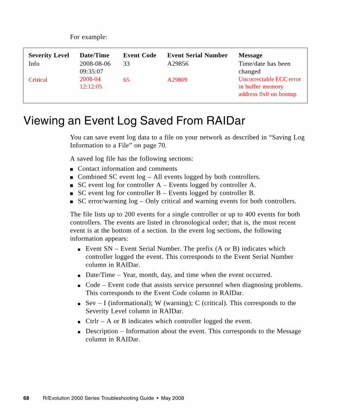
68 R/Evolution 2000 Series Troubleshooting Guide • May 2008
For example:
Viewing an Event Log Saved From RAIDarYou can save event log data to a file on your network as described in “Saving Log Information to a File” on page 70.
A saved log file has the following sections:■ Contact information and comments■ Combined SC event log – All events logged by both controllers.■ SC event log for controller A – Events logged by controller A.■ SC event log for controller B – Events logged by controller B.■ SC error/warning log – Only critical and warning events for both controllers.
The file lists up to 200 events for a single controller or up to 400 events for both controllers. The events are listed in chronological order; that is, the most recent event is at the bottom of a section. In the event log sections, the following information appears:
■ Event SN – Event Serial Number. The prefix (A or B) indicates which controller logged the event. This corresponds to the Event Serial Number column in RAIDar.
■ Date/Time – Year, month, day, and time when the event occurred.■ Code – Event code that assists service personnel when diagnosing problems.
This corresponds to the Event Code column in RAIDar.■ Sev – I (informational); W (warning); C (critical). This corresponds to the
Severity Level column in RAIDar.■ Ctrlr – A or B indicates which controller logged the event.■ Description – Information about the event. This corresponds to the Message
column in RAIDar.
Severity LevelInfo
Critical
Date/Time2008-08-06 09:35:072008-04 12:12:05
Event Code33
65
Event Serial NumberA29856
A29809
MessageTime/date has been changedUncorrectable ECC error in buffer memory address 0x0 on bootup
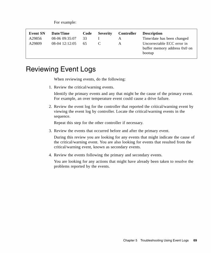
Chapter 5 Troubleshooting Using Event Logs 69
For example:
Reviewing Event LogsWhen reviewing events, do the following:
1. Review the critical/warning events. Identify the primary events and any that might be the cause of the primary event. For example, an over temperature event could cause a drive failure.
2. Review the event log for the controller that reported the critical/warning event by viewing the event log by controller. Locate the critical/warning events in the sequence.Repeat this step for the other controller if necessary.
3. Review the events that occurred before and after the primary event.During this review you are looking for any events that might indicate the cause of the critical/warning event. You are also looking for events that resulted from the critical/warning event, known as secondary events.
4. Review the events following the primary and secondary events.You are looking for any actions that might have already been taken to resolve the problems reported by the events.
Event SNA29856A29809
Date/Time08-06 09:35:0708-04 12:12:05
Code3365
SeverityIC
ControllerAA
DescriptionTime/date has been changedUncorrectable ECC error in buffer memory address 0x0 on bootup
70 R/Evolution 2000 Series Troubleshooting Guide • May 2008
Saving Log Information to a FileYou can save the following types of log information to a file:■ Device status summary, which includes basic status and configuration
information for the system.■ Event logs from both controllers when in active-active mode.■ Debug logs from both controllers when in active-active mode.■ Boot logs, which show the startup sequence for each controller.■ Up to four critical error dumps from each controller. These will exist only if
critical errors have occurred.■ Management Controller traces, which trace interface activity between the
controllers’ internal processors and activity on the management processor.
Note – The controllers share one memory buffer for gathering log data and for loading firmware. Do not try to perform more than one save-logs operation at a time, or to perform a firmware-update operation while performing a save-logs operation. Doing so will display a “buffer busy” error.
To save log information to a file:
1. Select Manage > Utilities > Debug Utilities > Save Logs To File.
2. Type contact information and comments to include in the log information file.Contact information provides the support representatives who are reviewing the file a means to identify who saved the log. Comments can explain why the logs are being saved and include pertinent information about system faults.
3. Under File Contents, select the logs to include in the file. By default, all logs are selected.
Note – Select logs judiciously. Gathering log data can be a lengthy operation, especially if the system is performing I/O.
4. Click Generate Log Information.When processing is complete, a summary page is displayed.
5. Review the summary of contact information, comments, and selected logs.
6. Click Download Selected Logs To File.
7. If prompted to open or save the file, click Save.
Chapter 5 Troubleshooting Using Event Logs 71
8. If prompted to specify the file location and name, do so using a .logs extension.The default file name is store.logs. If you intend to capture multiple event logs, be sure to name the files appropriately so that they can be identified later.
9. If you are using Firefox and have a download directory set, the file is automatically saved there.
Note – If you are using Firefox and have a download directory set, the file is automatically saved there.
Configuring the Debug LogWhen instructed to do so by service personnel, as an Advanced Manage user you can configure the debug log. The debug log captures data that will help engineering locate problems within the system logic.
After you configure the debug log as instructed, you will need to perform I/O to the system or re-create the situation that is causing the fault. This populates the debug log with information that engineering can use to diagnose the system.
Note – The debug log only collects data after you configure it. It will not contain information about any problems that occurred before you configure it.
To configure the debug log:
1. Select Manage > Utilities > Debug Utilities > Debug Log Setup. The Debug Log Setup page is displayed.
2. Select the debug log setup you want.■ Standard – Used for diagnosing general problems. With minimal impact on I/O
performance, it collects a wide range of debug data.■ I/O - Performance – Used for diagnosing I/O interface problems. Using this
option, the debug log is dedicated to collecting I/O interface information, with minimal impact on I/O performance.
■ Device-Side – Used for diagnosing device-side problems. It collects device failure data as well as I/O interface information, with minimal impact on I/O performance.
■ Device Management – Collects very verbose information, including all Configuration API (CAPI) transactions. Because this option collects a lot of data, it has a substantial impact on performance and quickly fills up the debug trace.
72 R/Evolution 2000 Series Troubleshooting Guide • May 2008
■ No Debug Tracing – Collects no debug data.■ Custom Debug Tracing – Shows that specific events are selected for inclusion in
the log. This is the default. If no events are selected, this option is not displayed.
3. Click Change Debug Logging Setup.
4. If instructed by service personnel, click Advanced Debug Logging Setup Options and select one or more additional types of events.Under normal conditions, none of these options should be selected because they have a slight impact on read/write performance.
73
CHAPTER 6
Voltage and Temperature Warnings
The storage system provides voltage and temperature warnings, which are generally input or environmental conditions. Voltage warnings can occur if the input voltage is too low or if a FRU is receiving too little or too much power from the power-and-cooling module. Temperature warnings are generally the result of a fan failure, a FRU being removed from an enclosure for a lengthy time period, or a high ambient temperature around an enclosure.
This chapter describes the steps to take to resolve voltage and temperature warnings and provides information about the power supply, cooling fan, temperature, and voltage sensor locations and alarm conditions. Topics covered in this chapter include:■ “Resolving Voltage and Temperature Warnings” on page 73■ “Sensor Locations” on page 74
Resolving Voltage and Temperature WarningsTo resolve voltage and temperature warnings:
1. Check that all of the fans are working by making sure each power-and-cooling module’s DC Voltage/Fan Fault/Service Required LED is off or by using the RAIDar Status Summary page (see “Determining Storage System Status and Verifying Faults” on page 37).
2. Make sure that all modules are fully seated in their slots and that their latches are locked.
3. Make sure that no slots are left open for more than two minutes. If you need to replace a module, leave the old module in place until you have the replacement or use a blank module to fill the slot. Leaving a slot open negatively affects the airflow and can cause the enclosure to overheat.
4. Try replacing each power-and-cooling module one at a time.
5. Replace the controller modules, one at a time.
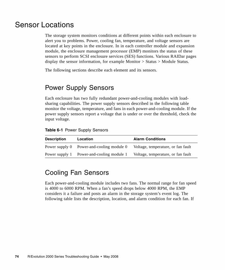
74 R/Evolution 2000 Series Troubleshooting Guide • May 2008
Sensor LocationsThe storage system monitors conditions at different points within each enclosure to alert you to problems. Power, cooling fan, temperature, and voltage sensors are located at key points in the enclosure. In in each controller module and expansion module, the enclosure management processor (EMP) monitors the status of these sensors to perform SCSI enclosure services (SES) functions. Various RAIDar pages display the sensor information, for example Monitor > Status > Module Status.
The following sections describe each element and its sensors.
Power Supply Sensors
Each enclosure has two fully redundant power-and-cooling modules with load-sharing capabilities. The power supply sensors described in the following table monitor the voltage, temperature, and fans in each power-and-cooling module. If the power supply sensors report a voltage that is under or over the threshold, check the input voltage.
Cooling Fan Sensors
Each power-and-cooling module includes two fans. The normal range for fan speed is 4000 to 6000 RPM. When a fan’s speed drops below 4000 RPM, the EMP considers it a failure and posts an alarm in the storage system’s event log. The following table lists the description, location, and alarm condition for each fan. If
Table 6-1 Power Supply Sensors
Description Location Alarm Conditions
Power supply 0 Power-and-cooling module 0 Voltage, temperature, or fan fault
Power supply 1 Power-and-cooling module 1 Voltage, temperature, or fan fault
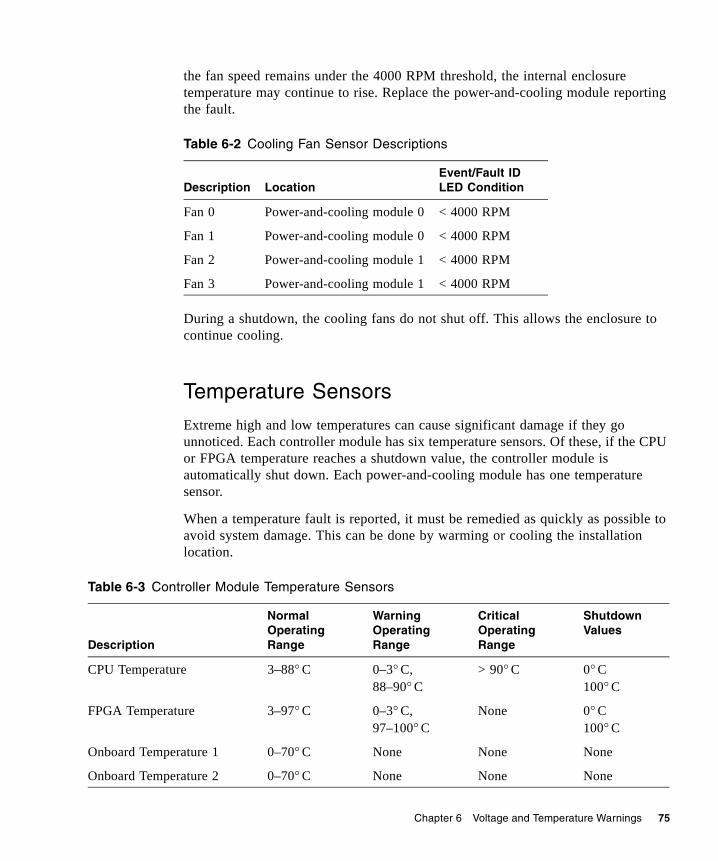
Chapter 6 Voltage and Temperature Warnings 75
the fan speed remains under the 4000 RPM threshold, the internal enclosure temperature may continue to rise. Replace the power-and-cooling module reporting the fault.
During a shutdown, the cooling fans do not shut off. This allows the enclosure to continue cooling.
Temperature Sensors
Extreme high and low temperatures can cause significant damage if they go unnoticed. Each controller module has six temperature sensors. Of these, if the CPU or FPGA temperature reaches a shutdown value, the controller module is automatically shut down. Each power-and-cooling module has one temperature sensor.
When a temperature fault is reported, it must be remedied as quickly as possible to avoid system damage. This can be done by warming or cooling the installation location.
Table 6-2 Cooling Fan Sensor Descriptions
Description LocationEvent/Fault ID LED Condition
Fan 0 Power-and-cooling module 0 < 4000 RPM
Fan 1 Power-and-cooling module 0 < 4000 RPM
Fan 2 Power-and-cooling module 1 < 4000 RPM
Fan 3 Power-and-cooling module 1 < 4000 RPM
Table 6-3 Controller Module Temperature Sensors
Description
Normal Operating Range
Warning Operating Range
Critical Operating Range
Shutdown Values
CPU Temperature 3–88° C 0–3° C, 88–90° C
> 90° C 0° C 100° C
FPGA Temperature 3–97° C 0–3° C, 97–100° C
None 0° C100° C
Onboard Temperature 1 0–70° C None None None
Onboard Temperature 2 0–70° C None None None
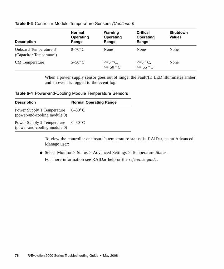
76 R/Evolution 2000 Series Troubleshooting Guide • May 2008
When a power supply sensor goes out of range, the Fault/ID LED illuminates amber and an event is logged to the event log.
To view the controller enclosure’s temperature status, in RAIDar, as an Advanced Manage user:
● Select Monitor > Status > Advanced Settings > Temperature Status.For more information see RAIDar help or the reference guide.
Onboard Temperature 3(Capacitor Temperature)
0–70° C None None None
CM Temperature 5–50° C <=5 ° C,>= 50 ° C
<=0 ° C,>= 55 ° C
None
Table 6-4 Power-and-Cooling Module Temperature Sensors
Description Normal Operating Range
Power Supply 1 Temperature(power-and-cooling module 0)
0–80° C
Power Supply 2 Temperature(power-and-cooling module 0)
0–80° C
Table 6-3 Controller Module Temperature Sensors (Continued)
Description
Normal Operating Range
Warning Operating Range
Critical Operating Range
Shutdown Values

Chapter 6 Voltage and Temperature Warnings 77
Power-and-Cooling Module Voltage Sensors
Power supply voltage sensors ensure that an enclosure’s power supply voltage is within normal ranges. There are three voltage sensors per power-and-cooling module.
Table 6-5 Voltage Sensor Descriptions
Sensor Event/Fault ID LED Condition
Power Supply 1 Voltage, 12V < 11.00V> 13.00V
Power Supply 1 Voltage, 5V < 4.00V> 6.00V
Power Supply 1 Voltage, 3.3V < 3.00V> 3.80V

78 R/Evolution 2000 Series Troubleshooting Guide • May 2008
79
CHAPTER 7
Troubleshooting and Replacing FRUs
This chapter describes how to troubleshoot and replace field-replaceable units. A field-replaceable unit (FRU) is a system component that is designed to be replaced onsite.
This chapter contains the following sections:■ “Static Electricity Precautions” on page 80■ “Identifying Controller or Expansion Module Faults” on page 80■ “Removing and Replacing a Controller or Expansion Module” on page 82■ “Updating Firmware” on page 90■ “Identifying SFP Module Faults” on page 92■ “Removing and Replacing an SFP Module” on page 93■ “Identifying Cable Faults” on page 95■ “Identifying Drive Module Faults” on page 96■ “Removing and Replacing a Drive Module” on page 104■ “Identifying Virtual Disk Faults” on page 110■ “Identifying Power-and-Cooling Module Faults” on page 112■ “Removing and Replacing a Power-and-Cooling Module” on page 114■ “Replacing an Enclosure” on page 116
80 R/Evolution 2000 Series Troubleshooting Guide • May 2008
Static Electricity PrecautionsTo prevent damaging a FRU, make sure you follow these static electricity precautions:■ Remove plastic, vinyl, and foam from the work area.■ Wear an antistatic wrist strap, attached to a ground.■ Before handling a FRU, discharge any static electricity by touching a ground
surface.■ Do not remove a FRU from its antistatic protective bag until you are ready to
install it.■ When removing a FRU from a controller enclosure, immediately place the FRU
in an antistatic bag and in antistatic packaging.■ Handle a FRU only by its edges and avoid touching the circuitry.■ Do not slide a FRU over any surface.■ Limit body movement (which builds up static electricity) during FRU
installation.
Identifying Controller or Expansion Module FaultsThe controller and expansion modules contain subcomponents that require the replacement of the entire FRU should they fail. Each controller and expansion module contains LEDs that can be used to identify a fault. Additionally, you can use RAIDar to locate and isolate controller and expansion module faults. (See “Troubleshooting Using RAIDar” on page 35.)
Note – When troubleshooting, ensure that you review the reported events carefully. The controller module is often the FRU reporting faults, but is not always the FRU where the fault is occurring.
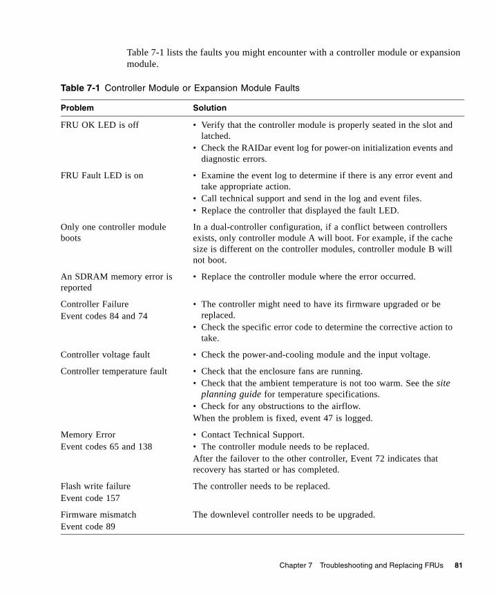
Chapter 7 Troubleshooting and Replacing FRUs 81
Table 7-1 lists the faults you might encounter with a controller module or expansion module.
Table 7-1 Controller Module or Expansion Module Faults
Problem Solution
FRU OK LED is off • Verify that the controller module is properly seated in the slot and latched.
• Check the RAIDar event log for power-on initialization events and diagnostic errors.
FRU Fault LED is on • Examine the event log to determine if there is any error event and take appropriate action.
• Call technical support and send in the log and event files.• Replace the controller that displayed the fault LED.
Only one controller module boots
In a dual-controller configuration, if a conflict between controllers exists, only controller module A will boot. For example, if the cache size is different on the controller modules, controller module B will not boot.
An SDRAM memory error is reported
• Replace the controller module where the error occurred.
Controller FailureEvent codes 84 and 74
• The controller might need to have its firmware upgraded or be replaced.
• Check the specific error code to determine the corrective action to take.
Controller voltage fault • Check the power-and-cooling module and the input voltage.
Controller temperature fault • Check that the enclosure fans are running.• Check that the ambient temperature is not too warm. See the site
planning guide for temperature specifications.• Check for any obstructions to the airflow.When the problem is fixed, event 47 is logged.
Memory ErrorEvent codes 65 and 138
• Contact Technical Support.• The controller module needs to be replaced.After the failover to the other controller, Event 72 indicates that recovery has started or has completed.
Flash write failureEvent code 157
The controller needs to be replaced.
Firmware mismatchEvent code 89
The downlevel controller needs to be upgraded.
82 R/Evolution 2000 Series Troubleshooting Guide • May 2008
Removing and Replacing a Controller or Expansion Module
In a dual-controller configuration, controller and expansion modules are hot-swappable, which means you can replace one module without halting I/O to the storage system or powering it off. In this case, the second module takes over operation of the storage system until you install the new module.
In a single-controller configuration, I/O to the storage system must be halted and the storage system must be powered off.
A controller or expansion module might need replacing when:■ The Fault/Service Required LED is illuminated■ Events in RAIDar indicate a problem with the module■ Troubleshooting indicates a problem with the module■ The internal clock battery fails
Caution – In a dual-controller configuration, both controllers must have the same cache size. If the new controller has a different cache size, controller A will boot and controller B will not boot. To view the cache size, select Monitor > Advanced Settings > Controller Versions.
Saving Configuration Settings
Before replacing a controller module, save the storage system’s configuration settings to file. This enables you to make a backup of your settings in case a subsequent configuration change causes a problem, or if you want to apply one system’s settings to another system.
The file contains all system configuration data, including: ■ LAN configuration settings■ Host port configuration settings■ Enclosure management settings■ Disk configuration settings■ Services security settings■ System information settings■ System preference settings■ Event notification settings
Chapter 7 Troubleshooting and Replacing FRUs 83
The configuration file does not include configuration data for virtual disks and volumes. You do not need to save this data before replacing a controller or expansion module because the data is saved as metadata in the first sectors of associated disk drives.
To save system configuration data to a file on the management host or network:
1. In RAIDar, connect to the IP address of one of the controller modules.
2. Select Manage > Utilities > Configuration Utilities > Save Config File.
3. Click Save Configuration File.
4. If prompted to open or save the file, click Save.
5. If prompted to specify the file location and name, do so using a .config extension. The default file name is saved_config.config.
Note – If you are using Firefox and have a download directory set, the file is automatically saved there.
In a dual-controller configuration, the storage system’s partner Firmware Upgrade option is enabled by default, so when you upgrade a controller, the system automatically ensures that both controllers have the most recent version.
Use RAIDar to verify that partner Firmware Update is enabled.
Select Monitor > Status > Advanced Settings > Misc Configuration to view the current setting.If partner Firmware Upgrade is disabled, select Manage > General Config > System Configuration, and then set Partner Firmware Upgrade to Enabled.
84 R/Evolution 2000 Series Troubleshooting Guide • May 2008
Shutting Down a Controller Module
Shut down a controller module before you remove it from an enclosure, or before you power off its enclosure for maintenance, repair, or a move. Shutting down a controller module halts I/O to that module, ensures that any data in the write cache is written to disk, and initiates failover to the partner controller, if it is active.
Caution – While both controllers are shut down, you have limited management capability for the storage system and host applications do not have access to its volumes. If you want the system to remain available, before shutting down one controller verify that the other controller is active.
To shut down a controller module:
1. Select Manage > Restart System > Shut Down/Restart.
2. In the Shut Down panel, select a controller option.
3. Click Shut Down.A warning might appear that data access redundancy will be lost until the selected controller is restarted. This is an informational message that requires no action.
4. Confirm the operation by clicking OK.
Note – If the storage system is connected to a Microsoft Windows host, the following event is recorded in the Windows event log: Initiator failed to connect to the target.
Chapter 7 Troubleshooting and Replacing FRUs 85
Removing a Controller Module or Expansion Module
As long as the other module in the enclosure you are removing remains online and active, you can remove a module without powering down the enclosure; however you must shut down a controller module as described in “Shutting Down a Controller Module” on page 84.
Caution – Removing the module impacts the airflow and cooling ability of the device. To avoid possible overheating, insert the replacement I/O module as quickly as possible. If the internal temperature exceeds acceptable limits, the enclosure may overheat and automatically shut down or restart.
Caution – When replacing a controller, ensure that less than 10 seconds elapse between inserting the controller into a slot and fully latching it in place. Failing to do so might cause the controller to fail. It it is not latched within 10 seconds, remove the controller from the slot and repeat the process.
Note – Although the illustrations provided in the following steps show a controller module, the instructions also apply to an expansion module.
To remove a controller module or expansion module:
1. Follow all static electricity precautions as described in “Static Electricity Precautions” on page 80.
2. If removing the controller module, use RAIDar to check the status of the partner module.To ensure continuous availability of the system, be sure that the partner module is online. If the partner is offline, resolve the problem with that module before continuing this procedure.
3. If you are removing a controller module and the partner module is online, use RAIDar to shut down the module that you want to remove; see “Shutting Down a Controller Module” on page 84.You need to use the Shut Down function for controller modules only. The blue OK to Remove LED illuminates to indicate that the module can be removed safely.
4. Use RAIDar to illuminate the Unit Locator LED of the enclosure that contains the module to remove.
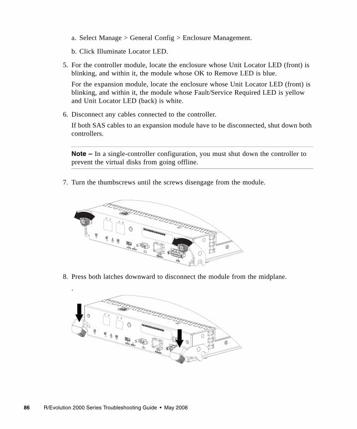
86 R/Evolution 2000 Series Troubleshooting Guide • May 2008
a. Select Manage > General Config > Enclosure Management.
b. Click Illuminate Locator LED.
5. For the controller module, locate the enclosure whose Unit Locator LED (front) is blinking, and within it, the module whose OK to Remove LED is blue. For the expansion module, locate the enclosure whose Unit Locator LED (front) is blinking, and within it, the module whose Fault/Service Required LED is yellow and Unit Locator LED (back) is white.
6. Disconnect any cables connected to the controller.If both SAS cables to an expansion module have to be disconnected, shut down both controllers.
Note – In a single-controller configuration, you must shut down the controller to prevent the virtual disks from going offline.
7. Turn the thumbscrews until the screws disengage from the module.
8. Press both latches downward to disconnect the module from the midplane.
.
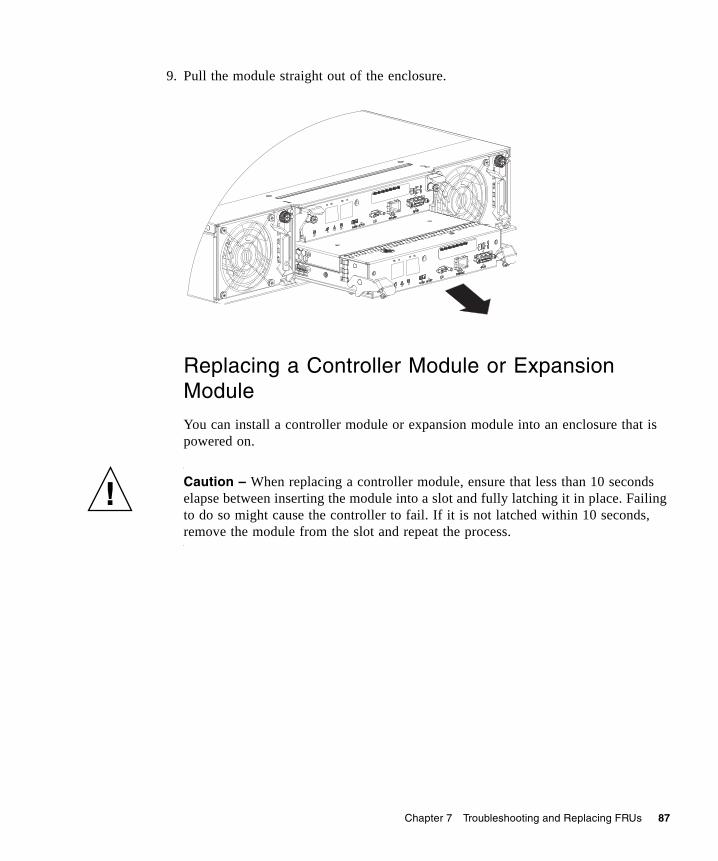
Chapter 7 Troubleshooting and Replacing FRUs 87
9. Pull the module straight out of the enclosure.
Replacing a Controller Module or Expansion Module
You can install a controller module or expansion module into an enclosure that is powered on.
Caution – When replacing a controller module, ensure that less than 10 seconds elapse between inserting the module into a slot and fully latching it in place. Failing to do so might cause the controller to fail. If it is not latched within 10 seconds, remove the module from the slot and repeat the process.
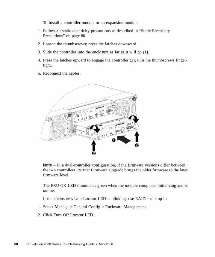
88 R/Evolution 2000 Series Troubleshooting Guide • May 2008
To install a controller module or an expansion module:
1. Follow all static electricity precautions as described in “Static Electricity Precautions” on page 80.
2. Loosen the thumbscrews; press the latches downward.
3. Slide the controller into the enclosure as far as it will go (1).
4. Press the latches upward to engage the controller (2); turn the thumbscrews finger-tight.
5. Reconnect the cables.
Note – In a dual-controller configuration, if the firmware versions differ between the two controllers, Partner Firmware Upgrade brings the older firmware to the later firmware level.
The FRU OK LED illuminates green when the module completes initializing and is online.
If the enclosure’s Unit Locator LED is blinking, use RAIDar to stop it:
1. Select Manage > General Config > Enclosure Management.
2. Click Turn Off Locator LED.
1
2
2
Chapter 7 Troubleshooting and Replacing FRUs 89
Fault/Service RequiredIf the Fault/Service Required yellow LED is illuminated, the module has not gone online and likely failed its self-test. Try to put the module online (see “Shutting Down a Controller Module” on page 84) or check for errors that were generated in the event log from RAIDar.
Boot Handshake Error
When powering on the controllers, if RAIDar or the event log report a boot handshake error, power off the enclosure for two seconds and then power it on again. If this does not correct the error, remove and replace each controller as described in “Removing a Controller Module or Expansion Module” on page 85.
Setting the Internal Clock
The clock battery is not a FRU. You must send in the controller module for service to have the battery replaced.
When the serviced controller module is reinserted into the enclosure, the controller’s date and time are automatically updated to match the date and time of the partner controller.
In a single controller configuration, you must set the clock manually. To set the date and time in RAIDar, select Manage > General Config > Set Date/Time.
Persistent IP Address
The IP address for each controller is stored in a SEEPROM on the midplane. The IP address is persistent. When you replace a controller, the new controller will have the same IP address as the old controller.
Moving a Set of Expansion Modules
The enclosure ID for the RAID controller is always zero. The expansion modules are then numbered from one to four. The number is visible on the front on the enclosure. If you move a single expansion module, or a set of expansion modules to another controller and reconnect them in a different order, it is likely that the enclosures will not be numbered in sequential order. If the enclosure IDs do not update correctly or are incorrectly ordered, use RAIDar to force the controller to
90 R/Evolution 2000 Series Troubleshooting Guide • May 2008
reorder the enclosure IDs. To minimize issues with enclosure IDs, always move a complete set of expansion modules and reconnect them in the same order as they were connected to the original controller module.
To rescan, as an Advanced Manage user:
1. Verify that both controllers are up.
2. Select Manage > Utilities > Disk Drive Utilities > Rescan.
In the Rescan For Devices panel, click Rescan.
Updating FirmwareOccasionally new firmware is released to provide new features and fixes to known issues. The firmware is updated during controller replacement or by using RAIDar.
Caution – Do not power off the storage system during a firmware upgrade. Doing so might cause irreparable damage to the controllers.
Updating Firmware During Controller Replacement
When a replacement controller is sent from the factory, it might have a more recent version of firmware installed than the surviving controller in your system. By default, when you insert the replacement controller, the system compares the firmware of the existing controller and that of the new controller. The controller with the older firmware automatically downloads the firmware from the controller with the more recent firmware (partner firmware upgrade). If told to do so by a service technician, you can disable the partner firmware upgrade function using RAIDar.
Chapter 7 Troubleshooting and Replacing FRUs 91
Disabling Partner Firmware Upgrade
The partner firmware upgrade option is enabled by default in RAIDar. Only disable this function if told to do so by a service technician.
1. Select Manage > General Config > System Configuration.
2. For Partner Firmware Upgrade, select Disable.
Updating Firmware Using RAIDar
RAIDar enables you to upgrade the firmware in your storage system when new releases are available.
Note – The controllers share one memory buffer for gathering log data and for loading firmware. Do not try to perform more than one firmware-update operation at a time, or to perform a firmware-update operation while performing a save-logs operation. Doing so will display a “buffer busy” error.
To update your firmware using RAIDar, perform the following steps:
1. Ensure that the software package file is saved to a location on your network that the storage system can access.
2. Select Manage > Update Software > Controller Software.The Load Software panel is displayed, which describes the update process and lists your current software versions.
3. Click Browse and select the software package file.
4. Click Load Software Package File. If the storage system finds a problem with the file, it shows a message at the top of the page. To resolve the problem, try the following:■ Be sure to select the software package file that you just downloaded.■ Download the file again, in case it got corrupted. Do not attempt to edit the file.After about 30 seconds, the Load Software to Controller Module panel is displayed. This page lets you know whether the file was validated and what software components are in the file. The storage system only updates the software that has changes.

92 R/Evolution 2000 Series Troubleshooting Guide • May 2008
5. Review the current and new software versions, and then click Proceed with Code Update.A Code Load Progress window is displayed to show the progress of the update, which can take several minutes to complete. Do not power off the storage system during the code load process. Once the firmware upload is complete, the controller resets after which the opposite controller automatically repeats the process to load the new firmware. When the update completes on the connected controller, you are logged out. Wait one minute for the controller to start and click Log In to reconnect to RAIDar.
Identifying SFP Module FaultsThe FC Controller enclosure uses small form-factor pluggable (SFP) transceivers to attach the enclosure to Fibre Channel data hosts.
Note – Remove any SFP that is not connected to another device. As the storage system monitors itself, it will generate several events for each unconnected SFP as if there were an error.
Identifying SFP faults is difficult because they are part of the data bus that consists of the SFP, a cable, another SFP, and an HBA. When a fault is reported, it can be caused by any component of the data bus.
Note – SFPs that have been dropped can be damaged. Problems resulting from a dropped SFP include intermittent errors and no link.
To identify a faulty SFP, utilize the link LED and perform the troubleshooting procedure described in “Using Controller Module Host Port LEDs” on page 25.
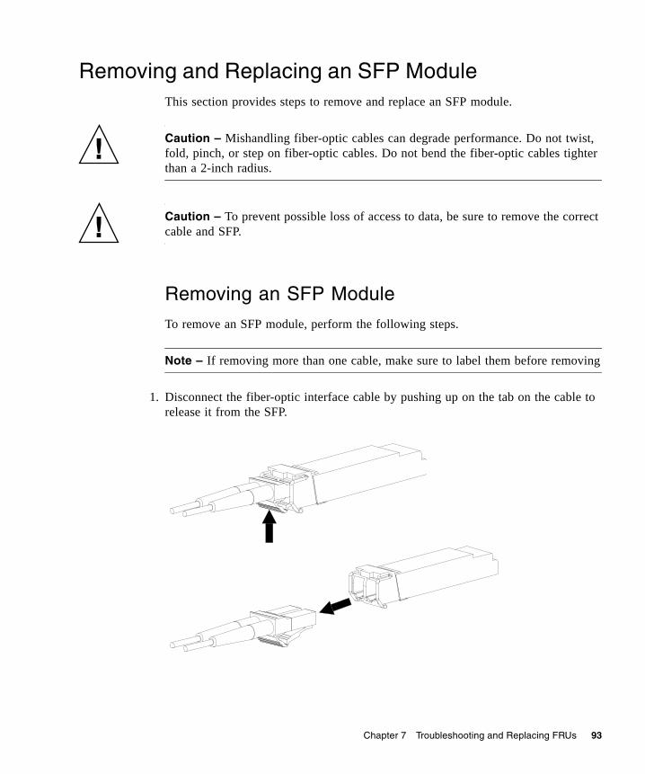
Chapter 7 Troubleshooting and Replacing FRUs 93
Removing and Replacing an SFP ModuleThis section provides steps to remove and replace an SFP module.
Caution – Mishandling fiber-optic cables can degrade performance. Do not twist, fold, pinch, or step on fiber-optic cables. Do not bend the fiber-optic cables tighter than a 2-inch radius.
Caution – To prevent possible loss of access to data, be sure to remove the correct cable and SFP.
Removing an SFP Module
To remove an SFP module, perform the following steps.
Note – If removing more than one cable, make sure to label them before removing
1. Disconnect the fiber-optic interface cable by pushing up on the tab on the cable to release it from the SFP.

94 R/Evolution 2000 Series Troubleshooting Guide • May 2008
2. The SFP is held in place by a small wire bail actuator; flip the actuator up and gently pull on it to remove the SFP from the controller.
Installing an SFP Module
To install an SFP module, perform the following steps:
1. If the SFP has a plug, remove it and slide the SFP into the port until it locks into place.
2. Flip the actuator down, and connect the fiber-optic interface cable into the duplex jack at the end of the SFP.
Chapter 7 Troubleshooting and Replacing FRUs 95
Identifying Cable FaultsWhen identifying cable faults you must remember that there are two sides of the controller: the input/output to the host and the input/output to the drive enclosures. It is also important to remember that identifying a cable fault can be difficult due to the multiple components that make up the data paths that cannot be overlooked as a cause of the fault.
Before you take to many troubleshooting steps, ensure you have reviewed the proper cabling steps in the getting started guide. Many faults can be eliminated by properly cabling the storage system.
Identifying Cable Faults on the Host Side
To identify a faulty cable on the host side, use the host link status LED and perform the troubleshooting procedure described in “Using Controller Module Host Port LEDs” on page 25.
Identifying Cable Faults on the Drive Enclosure Side
To identify a cable fault on the drive enclosure side, perform the troubleshooting procedure described in “Using Expansion Module LEDs” on page 33.
Disconnecting and Reconnecting SAS Cables
The storage system supports disconnecting and reconnecting SAS cables between enclosures while the system is active. You might need to do this as part of replacing an I/O module.
The guidelines are as follows:■ If less than 15 seconds elapses between disconnecting and reconnecting a cable
to the same port, no further action is required.■ If less than 15 seconds elapses between when disconnecting a cable and
connecting it to a different port in the same enclosure or in a different enclosure, you must perform a manual rescan. In RAIDar, select Manage > Utilities > Disk Drive Utilities > Rescan.
96 R/Evolution 2000 Series Troubleshooting Guide • May 2008
■ If at least 15 seconds elapses between disconnecting a cable and connecting it to a different port in the same enclosure or in a different enclosure, no further action is required.
Identifying Drive Module FaultsWhen identifying faults in drive modules you must:■ Understand disk-related errors■ Be able to determine if the error is due to a faulty disk drive or faulty disk drive
channel■ Identify what action the controller has taken to protect the virtual disk after the
drive fault occurred (that is, rebuilding to a hot-spare)■ Know how to identify disk drives in the enclosure■ Understand the proper procedure for replacing a faulty drive module
Understanding Disk-Related Errors
The event log includes errors reported by the enclosure management processors (EMPs) and disk drives in your storage system. If you see these errors in the event log, the following information will help you understand the errors.
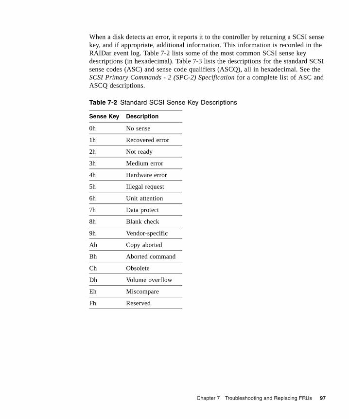
Chapter 7 Troubleshooting and Replacing FRUs 97
When a disk detects an error, it reports it to the controller by returning a SCSI sense key, and if appropriate, additional information. This information is recorded in the RAIDar event log. Table 7-2 lists some of the most common SCSI sense key descriptions (in hexadecimal). Table 7-3 lists the descriptions for the standard SCSI sense codes (ASC) and sense code qualifiers (ASCQ), all in hexadecimal. See the SCSI Primary Commands - 2 (SPC-2) Specification for a complete list of ASC and ASCQ descriptions.
Table 7-2 Standard SCSI Sense Key Descriptions
Sense Key Description
0h No sense
1h Recovered error
2h Not ready
3h Medium error
4h Hardware error
5h Illegal request
6h Unit attention
7h Data protect
8h Blank check
9h Vendor-specific
Ah Copy aborted
Bh Aborted command
Ch Obsolete
Dh Volume overflow
Eh Miscompare
Fh Reserved

98 R/Evolution 2000 Series Troubleshooting Guide • May 2008
Example
Below is an example of an error reported in the event log:
The drive in slot 10 of enclosure 1 reported a Sense Key Error of 2 and an ASC/ASCQ of 04/11.
Disk Drive Errors
In general media errors (sense key 3), recovery errors (sense key 1), and SMART events (identified by the following text in the event logs: “SMART event”) clearly point to a problem with a specific drive. Other events, such as protocol errors and I/O timeouts might suggest drive problems, but also might be indicative of poorly seated or faulty cables, problems with particular drive slots, or even problems with the drive’s dongle, a small printed circuit board attached to the drive carrier of each drive. Each of these events may result in a warning or critical notification in RAIDar and the event log.
Table 7-3 Common ASC and ASCQ Descriptions
ASC ASCQ Descriptions
0C 02 Write error – auto-reallocation failed
0C 03 Write error – recommend reassignment
11 00 Unrecovered read error
11 01 Read retries exhausted
11 02 Error too long to correct
11 03 Multiple read errors
11 04 Unrecovered read error – auto-reallocation failed
11 0B Unrecovered read error – recommend reassignment
11 0C Unrecovered read error – recommend rewrite the data
47 01h Data phase CRC error detected
DISK DETECTED ERR 1.10 02, 04,11.
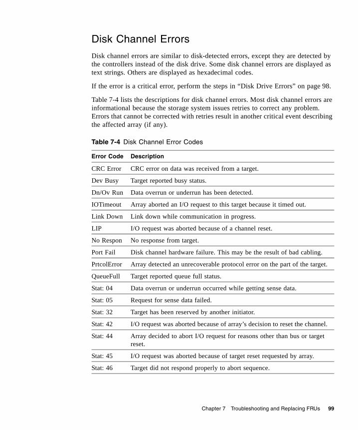
Chapter 7 Troubleshooting and Replacing FRUs 99
Disk Channel Errors
Disk channel errors are similar to disk-detected errors, except they are detected by the controllers instead of the disk drive. Some disk channel errors are displayed as text strings. Others are displayed as hexadecimal codes.
If the error is a critical error, perform the steps in “Disk Drive Errors” on page 98.
Table 7-4 lists the descriptions for disk channel errors. Most disk channel errors are informational because the storage system issues retries to correct any problem. Errors that cannot be corrected with retries result in another critical event describing the affected array (if any).
Table 7-4 Disk Channel Error Codes
Error Code Description
CRC Error CRC error on data was received from a target.
Dev Busy Target reported busy status.
Dn/Ov Run Data overrun or underrun has been detected.
IOTimeout Array aborted an I/O request to this target because it timed out.
Link Down Link down while communication in progress.
LIP I/O request was aborted because of a channel reset.
No Respon No response from target.
Port Fail Disk channel hardware failure. This may be the result of bad cabling.
PrtcolError Array detected an unrecoverable protocol error on the part of the target.
QueueFull Target reported queue full status.
Stat: 04 Data overrun or underrun occurred while getting sense data.
Stat: 05 Request for sense data failed.
Stat: 32 Target has been reserved by another initiator.
Stat: 42 I/O request was aborted because of array’s decision to reset the channel.
Stat: 44 Array decided to abort I/O request for reasons other than bus or target reset.
Stat: 45 I/O request was aborted because of target reset requested by array.
Stat: 46 Target did not respond properly to abort sequence.

100 R/Evolution 2000 Series Troubleshooting Guide • May 2008
Identifying Faulty Drive Modules
To identify faulty drive modules, perform the following steps:
1. Does the fault involve a single drive?■ If yes, perform steps Step 2 through Step 4.■ If an entire enclosure of disk drives is faulty, check your cabling and if necessary
perform the steps in “Identifying Cable Faults” on page 95.
2. Identify the suspected faulty disk drive using the LEDs.
3. Replace the suspected faulty disk drive with a known good drive (a replacement drive).
4. Does this correct the fault?■ If yes, the fault has been corrected and no further action is necessary.■ If no, continue to Step 5.
5. The fault may be caused by a bad disk drive slot on the midplane. Confirm your findings by powering off the storage system, moving an operating disk drive into the suspected slot, and re-applying power.
Note – Step 5 requires that you schedule down time for the system.
6. Does this drive fail when placed in the suspected slot?■ Yes, replace the enclosure. You have located the faulty FRU.■ No, continue to Step 7.
7. If it does not fail, move the drive back to it original slot and ensure the replacement drive is fully inserted into the slot.
8. To ensure that the controller detects all drives, power cycle the drive enclosure.
Note – Step 8 requires that you schedule down time for the system.
If the drive fails again the midplane may have an intermittent fault or the connector is dirty, replace the enclosure.

Chapter 7 Troubleshooting and Replacing FRUs 101
Updating Disk Drive Firmware
You can update disk drive firmware by loading a firmware update file obtained from the disk drive manufacturer or your reseller.
Note – Updating the firmware of disk drives in a virtual disk risks the loss of data and causes the drives to be temporarily inaccessible. Before performing a firmware update, perform the preparation tasks below.
To prepare to update disk drive firmware:
1. Obtain the firmware update file and store it in a network location that RAIDar can access.
2. If the drive is in a virtual disk, verify that it is not being initialized, expanded, or reconstructed. Select Manage > Virtual Disk Config > Vdisk Utility Progress.For each virtual disk, the virtual disk panel shows a status icon; the name, RAID level, size, number of disk drives, and number of volumes; and utility status, if any.For each virtual disk where a utility is running, a Utility Running For Virtual Disk panel specifies its status.
Note – To stop the Initialize or Verify utility, go to the Abort A Vdisk Utility page. To stop background scrub of virtual disks, go to the General Config > System Configuration page. You cannot stop the Expand or Reconstruct utility unless you delete the virtual disk.
If any of these tasks are in progress, wait for it to complete before performing the update. Then restart this procedure.
3. Ensure that no other user is performing administrative functions on the storage system.
4. Verify that background scrub is disabled.
a. Select Manage > General Config > System Configuration.
b. If it’s not already set to Disabled, set Background Scrub to Disabled.
c. Click Change System Configuration.
5. Back up the data for the virtual disk that the drive is part of.
102 R/Evolution 2000 Series Troubleshooting Guide • May 2008
6. Stop host I/O by either disconnecting data cables from the storage system controllers or powering down all hosts connected to the system.
To update disk drive firmware:
1. Select Manage > Update Software > Disk Drive Firmware > Update Firmware.
2. Select the type of disk drives to update.Drives that have the same manufacturer, model, and firmware revision are considered the same type. For example, two identical disk drives with different firmware revisions are considered to be different types. If firmware update is not supported for a disk drive type, the Select column shows “Not Supported” for that type and you cannot continue the firmware update process.
3. Click Select Type And Continue.Disk drives of the type you selected are listed and the following information is displayed for each disk drive:■ Device WWN – The disk drive’s node WWN.■ Address Port 0 – The channel and SCSI ID of the drive as accessed through
controller A.■ Address Port 1 – The channel and SCSI ID of the drive as accessed through
controller B.■ Size – The size of the disk drive in Gbyte.■ Manufacturer – The disk drive manufacturer.■ Model – The disk drive model number.■ Rev – The four-digit firmware revision code for the firmware currently on the
disk drive.■ Serial Number – The disk drive’s vendor-specific serial number.■ Virtual Disk Member – Specifies whether this disk drive is part of a virtual disk.If more than two drives are listed, a Select All check box is displayed.
4. Select the disk drives to update.
5. Click Continue.
6. Click Browse to select the firmware update file.
7. Click Load Device Firmware File.
Chapter 7 Troubleshooting and Replacing FRUs 103
8. To start the firmware update, click Start Firmware Update.To cancel the firmware update, click Cancel.The file is transferred to the controller where it is temporarily stored prior to download to the disk drives. Once the firmware update process has started, the Drive Firmware Loading Progress page provides the update progress of each disk drive, including when the firmware update completes successfully. This operation can take many minutes or hours to complete. During the update, the following operations are blocked so that they do not interfere with the update:■ Updating controller software (buffer interference)■ Saving logs to a file (buffer interference)■ Displaying disk drive read-cache status (SCSI interference)When all selected drives have been updated, a message indicates that the update is complete.
9. Verify that the proper firmware version, size, and speed are reported for each updated disk drive.
10. Restore host access to the storage system and optionally enable background scrub.
104 R/Evolution 2000 Series Troubleshooting Guide • May 2008
Removing and Replacing a Drive ModuleA drive module consists of a disk drive in a sled. Drive modules are hot-swappable, which means they can be replaced without halting I/O to the storage system or powering it off.
Caution – To prevent any possibility of data loss, back up data to another virtual disk or other location before removing the drive module.
Caution – When you replace a failed drive module for a degraded or critical virtual disk, the new module must be the same type (SAS or SATA) and must have a capacity equal to or greater than the drive module you are replacing. Otherwise the storage system cannot use the new disk drive to rebuild the virtual disk.
If you are using disk management software or volume management software to manage your disk storage, you might need to perform software operations to take a drive module offline before you remove it and then, after you have replaced it, to bring the new drive module online. See the documentation that accompanies your disk management software or volume management software for more information.
Replacing a Drive Module When the Virtual Disk Is Rebuilding
When a drive module fails or is removed, the system rebuilds the virtual disk by restoring any data that was on the failed disk drive onto a global spare or virtual disk spare, if one is available. If you replace more than one drive module at a time, the virtual disk cannot be rebuilt. If more than one drive module fails in a virtual disk (except RAID 6 and 10), the virtual disk fails and data from the virtual disk is lost.
When you want to replace a drive module and a virtual disk to which it belongs is being rebuilt, you have two options:■ Wait until the rebuild process is completed, and then replace the defective drive
module. The benefit is that the virtual disk is fully restored before you replace the defective drive. This eliminates the possibility of lost data if the wrong drive is removed.
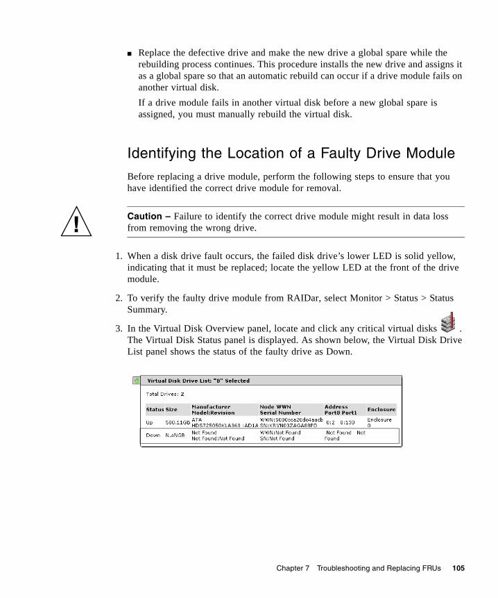
Chapter 7 Troubleshooting and Replacing FRUs 105
■ Replace the defective drive and make the new drive a global spare while the rebuilding process continues. This procedure installs the new drive and assigns it as a global spare so that an automatic rebuild can occur if a drive module fails on another virtual disk. If a drive module fails in another virtual disk before a new global spare is assigned, you must manually rebuild the virtual disk.
Identifying the Location of a Faulty Drive Module
Before replacing a drive module, perform the following steps to ensure that you have identified the correct drive module for removal.
Caution – Failure to identify the correct drive module might result in data loss from removing the wrong drive.
1. When a disk drive fault occurs, the failed disk drive’s lower LED is solid yellow, indicating that it must be replaced; locate the yellow LED at the front of the drive module.
2. To verify the faulty drive module from RAIDar, select Monitor > Status > Status Summary.
3. In the Virtual Disk Overview panel, locate and click any critical virtual disks . The Virtual Disk Status panel is displayed. As shown below, the Virtual Disk Drive List panel shows the status of the faulty drive as Down.
106 R/Evolution 2000 Series Troubleshooting Guide • May 2008
4. Replace the failed module by following the instructions in “Removing a Drive Module” on page 106.
You can also use the CLI show enclosure-status command. If the drive status is “Absent” the drive might have failed, or it has been removed from the chassis. For details on the show enclosure-status command, see the CLI reference guide.
Removing a Drive Module
When you remove a drive module, it is important to maintain optimum airflow through the chassis by either replacing it immediately with another one or by using an air management module. If you do not have a replacement module or an air management module, do not remove the drive module, that is, it is not harmful to the storage system to keep a fault drive inserted until you have a replacement drive. If you do have an air management module, it is installed using the same procedure for removing a drive module as described below.
Caution – If you remove a drive module and do not replace it within two minutes, you alter the air flow inside the enclosure, which could cause overheating of the enclosure. Do not remove a drive module unless you have a replacement drive module or air management module to immediately replace the one you removed.
To remove a drive from an enclosure, perform the following steps:
1. Follow all static electricity precautions as described in “Static Electricity Precautions” on page 80.
2. Squeeze the release on the left edge of the drive ejector handle.
3. Rotate the handle toward the right to disengage the drive module from the enclosure’s internal connector.
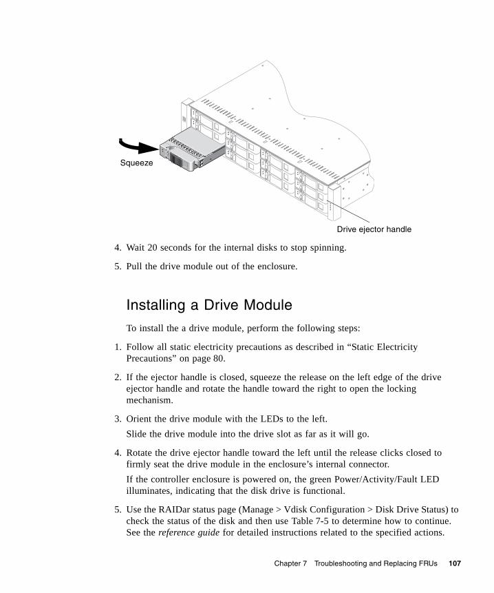
Chapter 7 Troubleshooting and Replacing FRUs 107
4. Wait 20 seconds for the internal disks to stop spinning.
5. Pull the drive module out of the enclosure.
Installing a Drive Module
To install the a drive module, perform the following steps:
1. Follow all static electricity precautions as described in “Static Electricity Precautions” on page 80.
2. If the ejector handle is closed, squeeze the release on the left edge of the drive ejector handle and rotate the handle toward the right to open the locking mechanism.
3. Orient the drive module with the LEDs to the left. Slide the drive module into the drive slot as far as it will go.
4. Rotate the drive ejector handle toward the left until the release clicks closed to firmly seat the drive module in the enclosure’s internal connector. If the controller enclosure is powered on, the green Power/Activity/Fault LED illuminates, indicating that the disk drive is functional.
5. Use the RAIDar status page (Manage > Vdisk Configuration > Disk Drive Status) to check the status of the disk and then use Table 7-5 to determine how to continue. See the reference guide for detailed instructions related to the specified actions.
Squeeze
Drive ejector handle
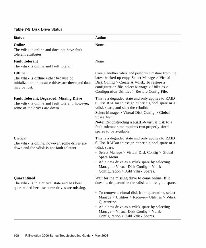
108 R/Evolution 2000 Series Troubleshooting Guide • May 2008
Table 7-5 Disk Drive Status
Status Action
OnlineThe vdisk is online and does not have fault tolerant attributes.
None
Fault TolerantThe vdisk is online and fault tolerant.
None
OfflineThe vdisk is offline either because of initialization or because drives are down and data may be lost.
Create another vdisk and perform a restore from the latest backed up copy. Select Manage > Virtual Disk Config > Create A Vdisk. To restore a configuration file, select Manage > Utilities > Configuration Utilities > Restore Config File.
Fault Tolerant, Degraded, Missing DriveThe vdisk is online and fault tolerant, however, some of the drives are down.
This is a degraded state and only applies to RAID 6. Use RAIDar to assign either a global spare or a vdisk spare, and start the rebuild: Select Manage > Virtual Disk Config > Global Spare Menu.Note: Reconstructing a RAID-6 virtual disk to a fault-tolerant state requires two properly sized spares to be available.
CriticalThe vdisk is online, however, some drives are down and the vdisk is not fault tolerant.
This is a degraded state and only applies to RAID 6. Use RAIDar to assign either a global spare or a vdisk spare. • Select Manage > Virtual Disk Config > Global
Spare Menu.• Ad a new drive as a vdisk spare by selecting
Manage > Virtual Disk Config > Vdisk Configuration > Add Vdisk Spares.
Quarantined The vdisk is in a critical state and has been quarantined because some drives are missing.
Wait for the missing drive to come online. If it doesn’t, dequarantine the vdisk and assign a spare.
• To remove a virtual disk from quarantine, select Manage > Utilities > Recovery Utilities > Vdisk Quarantine.
• Ad a new drive as a vdisk spare by selecting Manage > Virtual Disk Config > Vdisk Configuration > Add Vdisk Spares.
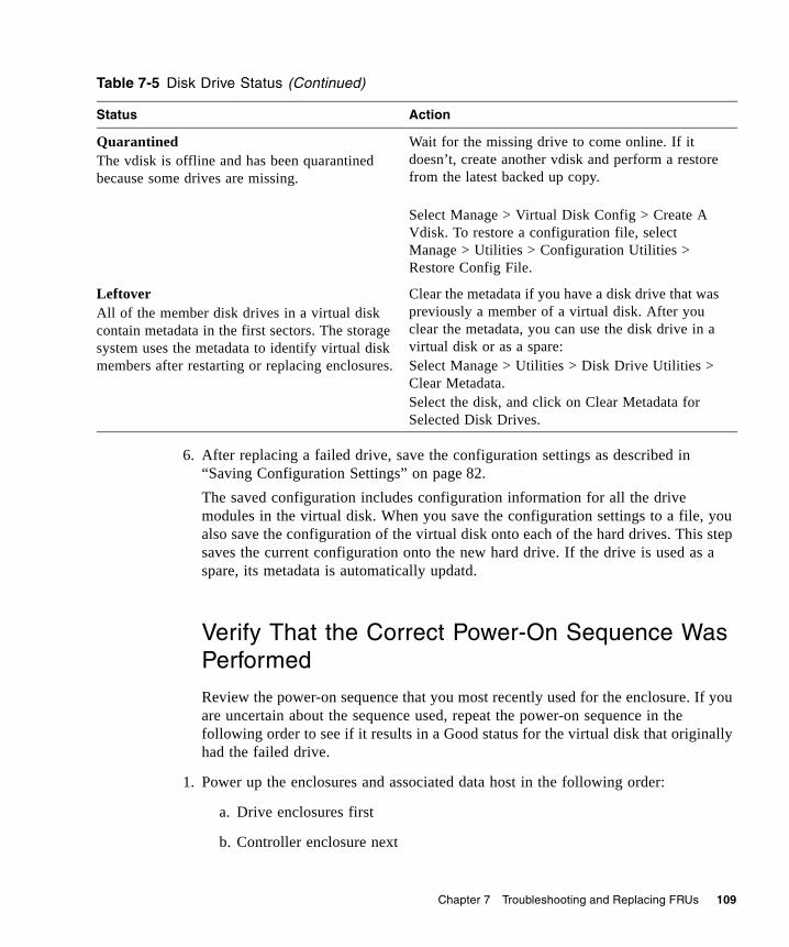
Chapter 7 Troubleshooting and Replacing FRUs 109
6. After replacing a failed drive, save the configuration settings as described in “Saving Configuration Settings” on page 82. The saved configuration includes configuration information for all the drive modules in the virtual disk. When you save the configuration settings to a file, you also save the configuration of the virtual disk onto each of the hard drives. This step saves the current configuration onto the new hard drive. If the drive is used as a spare, its metadata is automatically updatd.
Verify That the Correct Power-On Sequence Was Performed
Review the power-on sequence that you most recently used for the enclosure. If you are uncertain about the sequence used, repeat the power-on sequence in the following order to see if it results in a Good status for the virtual disk that originally had the failed drive.
1. Power up the enclosures and associated data host in the following order:
a. Drive enclosures first
b. Controller enclosure next
QuarantinedThe vdisk is offline and has been quarantined because some drives are missing.
Wait for the missing drive to come online. If it doesn’t, create another vdisk and perform a restore from the latest backed up copy.
Select Manage > Virtual Disk Config > Create A Vdisk. To restore a configuration file, select Manage > Utilities > Configuration Utilities > Restore Config File.
LeftoverAll of the member disk drives in a virtual disk contain metadata in the first sectors. The storage system uses the metadata to identify virtual disk members after restarting or replacing enclosures.
Clear the metadata if you have a disk drive that was previously a member of a virtual disk. After you clear the metadata, you can use the disk drive in a virtual disk or as a spare:Select Manage > Utilities > Disk Drive Utilities > Clear Metadata.Select the disk, and click on Clear Metadata for Selected Disk Drives.
Table 7-5 Disk Drive Status (Continued)
Status Action

110 R/Evolution 2000 Series Troubleshooting Guide • May 2008
c. Data hosts last (if they had been powered down for maintenance purposes)
2. In RAIDar, select Monitor > Status > Vdisk Status to display the virtual disk overview panel. This panel displays an icon for each virtual disk with information about the virtual disk below it.
Installing an Air Management Module
An air management module looks like a drive module; however, it is an empty box used to maintain optimum airflow and proper cooling in an enclosure. If your system was ordered with less than 12 drive modules it was shipped with air management modules for the slots without drive modules. Optionally, air management modules can be ordered.
If you must remove a drive module and cannot immediately replace it, you must leave the faulty drive module in place, or insert an air management module to maintain the optimum airflow inside the chassis. The blank is installed using the same procedure as “Installing a Drive Module” on page 107.
Identifying Virtual Disk FaultsObvious virtual disk problems involve the failure of a member disk drive. However, there are a number of not so obvious issues that result in virtual disk faults as seen in Table 7-6.
Table 7-6 Virtual Disk Faults
Problem Solution
Expanding virtual disk requires days to complete.
• In general, expanding a virtual disk can take days to complete. You cannot stop the expansion once it is started.
• If you have an immediate need, create a new virtual disk of the size you want, transfer your data to the new virtual disk, and delete the old virtual disk.

Chapter 7 Troubleshooting and Replacing FRUs 111
Failover causes a virtual disk to become critical when one of its drives “disappears.”
• In general, controller failover is not supported if a disk drive is in a drive enclosure that is connected with only one cable to the controller enclosure. This is because access to the drive enclosure will be lost if the controller to which it is connected fails. When the controller with the direct connection to the drive enclosure comes back online, access to the drive enclosure drives is restored. To avoid this problem, ensure that two cables are used to connect the enclosures as shown in the Getting Started Guide, and that the cables are connected securely and are not damaged.
• If the problem persists or affects a disk drive in a controller enclosure, a hardware problem might have occurred in the drive module, dongle, midplane, or controller module. Identify and replace the FRU where the problem occurred
A virtual disk is much smaller than it should be.
Verify that the disk drives are all the same size within the virtual disk. The virtual disk is limited by the smallest sized disk.
Volumes in the virtual disk are not visible to the host.
Verify that the volumes are mapped to the host using RAIDar:Manage > Volume Management > Volume Mapping > Map Hosts to Volume.
Virtual Disk DegradedEvent codes 58 and 1, or event codes 8 and 1
• Replace the failed disk drive and add the replaced drive as a spare to the critical virtual disk.
• If you have dynamic spares enabled, you only need to replace the drive. The system will automatically reconstruct the virtual disk.
Virtual Disk FailureEvent codes 58 and 3, or event codes 8 and 3
Replace the bad disk drive and restore the data from backup.
Virtual Disk QuarantinedEvent code 172
Ensure that all drives are turned on. When the vdisk is de-quarantined, event code 79 is returned.
Spare Disk FailureEvent code 62
• Replace the disk.
• If this disk was a dedicated spare for a vdisk, assign another spare to the vdisk.
Spare Disk UnusableEvent code 78
• The disk might not have a great enough capacity for the vdisk.
• Replace the spare with a disk that has a capacity equal to or greater than the smallest disk in the vdisk.
Table 7-6 Virtual Disk Faults (Continued)
Problem Solution
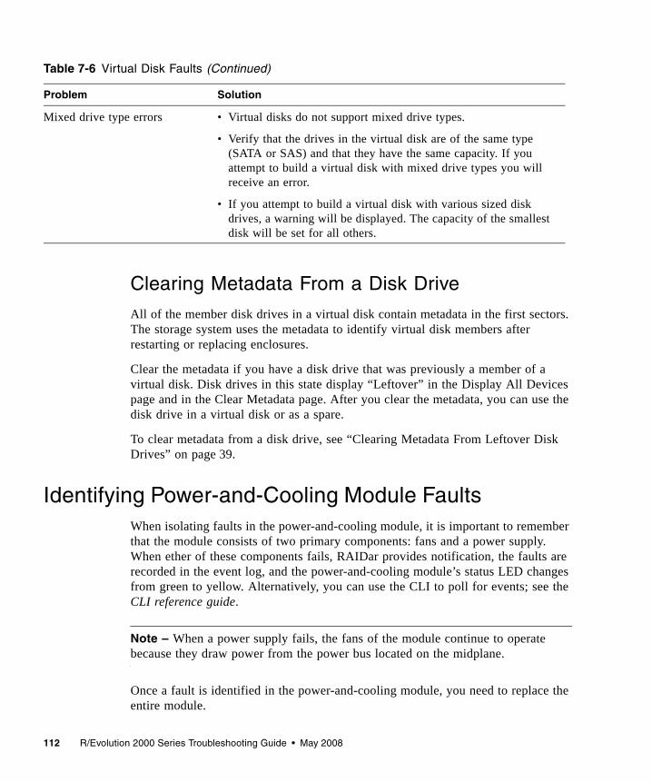
112 R/Evolution 2000 Series Troubleshooting Guide • May 2008
Clearing Metadata From a Disk Drive
All of the member disk drives in a virtual disk contain metadata in the first sectors. The storage system uses the metadata to identify virtual disk members after restarting or replacing enclosures.
Clear the metadata if you have a disk drive that was previously a member of a virtual disk. Disk drives in this state display “Leftover” in the Display All Devices page and in the Clear Metadata page. After you clear the metadata, you can use the disk drive in a virtual disk or as a spare.
To clear metadata from a disk drive, see “Clearing Metadata From Leftover Disk Drives” on page 39.
Identifying Power-and-Cooling Module FaultsWhen isolating faults in the power-and-cooling module, it is important to remember that the module consists of two primary components: fans and a power supply. When ether of these components fails, RAIDar provides notification, the faults are recorded in the event log, and the power-and-cooling module’s status LED changes from green to yellow. Alternatively, you can use the CLI to poll for events; see the CLI reference guide.
Note – When a power supply fails, the fans of the module continue to operate because they draw power from the power bus located on the midplane.
Once a fault is identified in the power-and-cooling module, you need to replace the entire module.
Mixed drive type errors • Virtual disks do not support mixed drive types.
• Verify that the drives in the virtual disk are of the same type (SATA or SAS) and that they have the same capacity. If you attempt to build a virtual disk with mixed drive types you will receive an error.
• If you attempt to build a virtual disk with various sized disk drives, a warning will be displayed. The capacity of the smallest disk will be set for all others.
Table 7-6 Virtual Disk Faults (Continued)
Problem Solution
Chapter 7 Troubleshooting and Replacing FRUs 113
Caution – Because removing the power-and-cooling module significantly disrupts the enclosure’s airflow, do not remove the power-and-cooling module until you have the replacement module.
Table 7-7 lists possible power-and-cooling module faults.
Table 7-7 Power-and-Cooling Module Faults
Fault Solution
Power supply fan warning or failure, orpower supply warning or failure. Event code 168
• Check that all of the fans are working using RAIDar.
• Make sure that no slots are left open for more than 2 minutes. If you need to replace a module, leave the old module in place until you have the replacement, or use a blank cover to close the slot. Leaving a slot open negatively affects the airflow and might cause the unit to overhead.
• Make sure that the controller modules are properly seated in their slots and that their latches are locked.
Power-and-cooling module status is listed as failed or you receive a voltage event notification. Event code 168
• Check that the switch on each power-and-cooling module is turned on.
• Check that the power cables are firmly plugged into both power-and-cooling modules and into an appropriate electrical outlet.
• Replace the power-and-cooling module.
AC Power LED is off. Same as above.
DC Voltage & Fan Fault/Service LED is on. Replace the power-and-cooling module.
114 R/Evolution 2000 Series Troubleshooting Guide • May 2008
Removing and Replacing a Power-and-Cooling Module
A single power-and-cooling module is sufficient to maintain operation of the enclosure. It is not necessary to halt operations and completely power off the enclosure when replacing only one power-and-cooling module.
Caution – When you remove a power-and-cooling module, install the new module within two minutes of removing the old module. The enclosure might overheat if you take more than two minutes to replace the power-and-cooling module.
Removing a Power-and-Cooling Module
To remove a power-and-cooling module from an enclosure, perform the following steps:
1. Follow all static electricity precautions as described in “Static Electricity Precautions” on page 80.
2. Turn the power switch off and disconnect the power cable.
3. Rotate the latch downward to disconnect the internal connector, and slide the module out.
Note – Do not lift the power-and-cooling module by the latch. This could break the latch. Hold the power-and-cooling module by the metal casing.
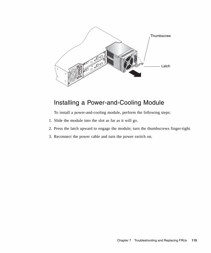
Chapter 7 Troubleshooting and Replacing FRUs 115
Installing a Power-and-Cooling Module
To install a power-and-cooling module, perform the following steps:
1. Slide the module into the slot as far as it will go.
2. Press the latch upward to engage the module; turn the thumbscrews finger-tight.
3. Reconnect the power cable and turn the power switch on.
Thumbscrew
Latch
116 R/Evolution 2000 Series Troubleshooting Guide • May 2008
Replacing an EnclosureThe enclosure consists of an enclosure’s metal housing and the midplane that connects controller/expansion modules, drive modules, and power-and-cooling modules. This FRU replaces an enclosure that has been damaged or whose midplane has been damaged. Often times a damaged midplane will appear as though a controller module has failed. If you replace a controller module and it does not remedy the original fault, replace the enclosure.
To make a fully functional enclosure, you must insert the following parts from the replaced enclosure:■ Drive modules and air management modules■ Two power-and-cooling modules■ One or two controller modules (for a controller enclosure)■ One or two expansion modules (for a drive enclosure)
To install the individual modules, use the replacement instructions provided in this guide. To configure the enclosure, see the getting started guide. The IP address for the controllers is maintained on the midplane. When you replace the enclosure, you need to reset the IP address as described in the getting started guide.
Caution – If connected data hosts are not inactive during this replacement procedure, data loss could occur.
117
APPENDIX A
Troubleshooting Using the CLI
This appendix briefly describes CLI commands that are useful for troubleshooting storage system problems. For detailed information about command syntax and using the CLI, see the CLI reference guide.
Topics covered in this appendix include:■ “Viewing Command Help” on page 118■ “clear cache” on page 118■ “clear expander-status” on page 118■ “ping” on page 119■ “rescan” on page 119■ “reset host-channel-link” on page 119■ “restart” on page 119■ “restore defaults” on page 120■ “set debug-log-parameters” on page 120■ “set expander-fault-isolation” on page 121■ “set expander-phy” on page 121■ “set led” on page 121■ “set protocols” on page 121■ “show debug-log” on page 122■ “show debug-log-parameters” on page 122■ “show enclosure-status” on page 122■ “show events” on page 123■ “show expander-status” on page 123■ “show frus” on page 123■ “show protocols” on page 123■ “show redundancy-mode” on page 124■ “trust” on page 124■ “Problems Scheduling Tasks” on page 125■ “Missing Parameter Data Error” on page 126
118 R/Evolution 2000 Series Troubleshooting Guide • May 2008
Viewing Command HelpTo view brief descriptions of all commands that are available to the user level you logged in as, type:
To view help for a specific command, type either:
To view information about the syntax to use for specifying disk drives, virtual disks, volumes, and volume mapping, type:
clear cacheClears any unwritable cache in both RAID controllers for a specified volume, or any orphaned data for volumes that no longer exist. This command can be used with a dual-controller configuration only.
For details about using clear cache, see the CLI reference guide.
clear expander-status
Note – This command should only be used by service technicians, or with the advice of a service technician.
Clears the counters and status for SAS Expander Controller lanes. Counters and status can be reset to a good state for all enclosures, or for a specific enclosure whose status is ERROR as shown by the show expander-status command.
For details about using clear expander-status, see the CLI reference guide.
# help
# help command# command ?
# help syntax
Appendix A Troubleshooting Using the CLI 119
pingTests communication with a remote host. The remote host is specified by IP address. Ping sends ICMP echo response packets and waits for replies.
For details about using ping, see the CLI reference guide.
rescanWhen installing a system with drive enclosures attached, the enclosure IDs might not agree with the physical cabling order. This is because the controller might have been previously attached to some of the same enclosures and it attempts to preserve the previous enclosure IDs if possible. To correct this condition, make sure that both controllers are up and perform a rescan using the CLI.
For details see the CLI reference guide.
reset host-channel-linkIssues a loop initialization primitive (LIP) from specified controllers on specified channels. This command is for use with an FC system using FC-AL (loop) topology.
For details about using reset host-channel-link, see the CLI reference guide.
restartRestarts the RAID controller or the Management Controller in either or both controller modules.
If you restart a RAID controller, it attempts to shut down with a proper failover sequence, which includes stopping all I/O operations and flushing the write cache to disk, and then the controller restarts. The Management Controllers are not restarted so they can provide status information to external interfaces.
If you restart a Management Controller, communication with it is temporarily lost until it successfully restarts. If the restart fails, the partner Management Controller remains active with full ownership of operations and configuration information.
Caution – If you restart both controller modules, you and users lose access to the system and its data until the restart is complete.
120 R/Evolution 2000 Series Troubleshooting Guide • May 2008
Note – If the storage system is connected to a Microsoft Windows host, the following event is recorded in the Windows event log: Initiator failed to connect to the target.
For details about using restart, see the CLI reference guide.
restore defaults
Note – This command should only be used by service technicians, or with the advice of a service technician.
Restores the manufacturer's default configuration to the controllers. When the command informs you that the configuration has been restored, you must restart the RAID controllers and Management Controllers for the changes to take effect. After restarting the controllers, hosts might not be able to access volumes until you re-map them.
Caution – This command changes how the system operates and might require some reconfiguration to restore host access to volumes.
For details about using restore defaults, see the CLI reference guide.
set debug-log-parameters
Note – This command should only be used by service technicians, or with the advice of a service technician.
Sets the types of debug messages to include in the Storage Controller debug log. If multiple types are specified, use spaces to separate them and enclose the list in quotation marks (").
For details about using set debug-log-parameters, see the CLI reference guide.
Appendix A Troubleshooting Using the CLI 121
set expander-fault-isolationWhen fault isolation is enabled, the Expander Controller will isolate PHYs that fail to meet certain criteria. When fault isolation is disabled, the errors are noted in the logs but the PHYs are not isolated.
For details about using set expander-fault-isolation, see the CLI reference guide.
set expander-phyThe Expander Controller will enable or disable (isolate) the specified PHY.
For details about using set expander-phy, see the CLI reference guide.
set ledChanges the state of drive module or enclosure LEDs to help you locate devices. For a drive module, the Power/Activity/Fault LED will blink yellow. For an enclosure, the Unit Locator LED on the chassis ear and on each controller module will blink white.
For details about using set led, see the CLI reference guide.
set protocolsEnables or disables one or more of the following service and security protocols.■ http, for standard access to RAIDar■ https, for secure access to RAIDar■ telnet, for standard access to the CLI■ ssh, for secure access to the CLI■ ftp, an alternate interface for firmware upgrade■ Storage Management Initiative Specification (SMI-S)■ Simple Network Management Protocol (SNMP)■ Telnet service port 1023■ Telnet debug port 4048■ In-band CAPI management interface■ In-band SES management interface
For details about using set protocols, see the CLI reference guide.
122 R/Evolution 2000 Series Troubleshooting Guide • May 2008
show debug-log
Note – This command should only be used by service technicians, or with the advice of a service technician.
Shows the debug logs for the Storage Controller (SC), the Management Controller (MC), the semaphore trace, task logs, or all of them. If no logs are specified, all logs are shown.
For details about using show debug-log, see the CLI reference guide.
show debug-log-parameters
Note – This command should only be used by service technicians, or with the advice of a service technician.
Shows which debug message types are enabled (on) or disabled (off) for inclusion in the Storage Controller debug log.
For details about using show debug-log-parameters, see the CLI reference guide.
show enclosure-statusShows the status of system enclosures and their components. For each attached enclosure, the command shows general SCSI Enclosure Services (SES) information followed by component-specific information.
For details about using show enclosure-status, see the CLI reference guide.
Appendix A Troubleshooting Using the CLI 123
show eventsShows events for an enclosure, including events from each Management Controller and each Storage Controller. A separate set of event numbers is maintained for each controller module. Each event number is prefixed with a letter identifying the controller module that logged the event.
If SNMP is configured, events can be sent to SNMP traps.
For details about using show events, see the CLI reference guide.
show expander-status
Note – This command should only be used by service technicians, or with the advice of a service technician.
Shows diagnostic information relating to SAS Expander Controller physical channels, known as PHY lanes. For each enclosure, this command shows status information for PHYs in I/O module A and then I/O module B.
For details about using show expander-status, see the CLI reference guide.
show frusShows information for all field-replaceable units (FRUs) in the controller enclosure and in any attached drive enclosures. Some information reported is for use by service technicians.
For details about using show frus, see the CLI reference guide.
show protocolsShows which service and security protocols are enabled or disabled.
For details about using show protocols, see the CLI reference guide.
124 R/Evolution 2000 Series Troubleshooting Guide • May 2008
show redundancy-modeShows the redundancy status of the system.
For details about using show redundancy-mode, see the CLI reference guide.
trustEnables an offline virtual disk to be brought online for emergency data collection only. It must be enabled before each use.
Caution – This command can cause unstable operation and data loss if used improperly. It is intended for disaster recovery only.
The trust command re-synchronizes the time and date stamp and any other metadata on a bad disk drive. This makes the disk drive an active member of the virtual disk again. You might need to do this when:■ One or more disks of a virtual disk start up more slowly or were powered on after
the rest of the disks in the virtual disk. This causes the date and time stamps to differ, which the system interprets as a problem with the “late” disks. In this case, the virtual disk functions normally after being trusted.
■ A virtual disk is offline because a drive is failing, you have no data backup, and you want to try to recover the data from the virtual disk. In this case, trust may work, but only as long as the failing drive continues to operate.
When the “trusted” virtual disk is back online, back up its data and audit the data to make sure that it is intact. Then delete that virtual disk, create a new virtual disk, and restore data from the backup to the new virtual disk. Using a trusted virtual disk is only a disaster-recovery measure; the virtual disk has no tolerance for any additional failures.
For details about using trust, see the CLI reference guide.
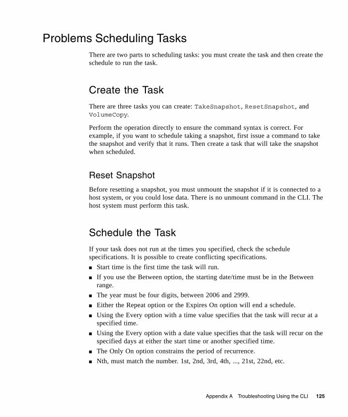
Appendix A Troubleshooting Using the CLI 125
Problems Scheduling TasksThere are two parts to scheduling tasks: you must create the task and then create the schedule to run the task.
Create the Task
There are three tasks you can create: TakeSnapshot, ResetSnapshot, and VolumeCopy.
Perform the operation directly to ensure the command syntax is correct. For example, if you want to schedule taking a snapshot, first issue a command to take the snapshot and verify that it runs. Then create a task that will take the snapshot when scheduled.
Reset Snapshot
Before resetting a snapshot, you must unmount the snapshot if it is connected to a host system, or you could lose data. There is no unmount command in the CLI. The host system must perform this task.
Schedule the Task
If your task does not run at the times you specified, check the schedule specifications. It is possible to create conflicting specifications.■ Start time is the first time the task will run.■ If you use the Between option, the starting date/time must be in the Between
range.■ The year must be four digits, between 2006 and 2999.■ Either the Repeat option or the Expires On option will end a schedule.■ Using the Every option with a time value specifies that the task will recur at a
specified time.■ Using the Every option with a date value specifies that the task will recur on the
specified days at either the start time or another specified time.■ The Only On option constrains the period of recurrence.■ Nth, must match the number. 1st, 2nd, 3rd, 4th, ..., 21st, 22nd, etc.
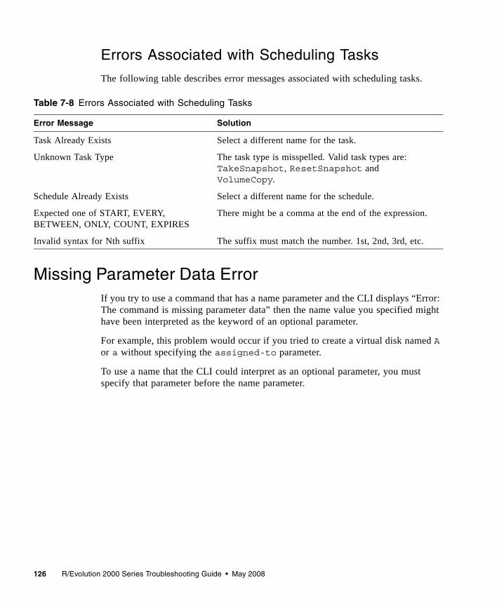
126 R/Evolution 2000 Series Troubleshooting Guide • May 2008
Errors Associated with Scheduling Tasks
The following table describes error messages associated with scheduling tasks.
Missing Parameter Data ErrorIf you try to use a command that has a name parameter and the CLI displays “Error: The command is missing parameter data” then the name value you specified might have been interpreted as the keyword of an optional parameter.
For example, this problem would occur if you tried to create a virtual disk named A or a without specifying the assigned-to parameter.
To use a name that the CLI could interpret as an optional parameter, you must specify that parameter before the name parameter.
Table 7-8 Errors Associated with Scheduling Tasks
Error Message Solution
Task Already Exists Select a different name for the task.
Unknown Task Type The task type is misspelled. Valid task types are: TakeSnapshot, ResetSnapshot and VolumeCopy.
Schedule Already Exists Select a different name for the schedule.
Expected one of START, EVERY, BETWEEN, ONLY, COUNT, EXPIRES
There might be a comma at the end of the expression.
Invalid syntax for Nth suffix The suffix must match the number. 1st, 2nd, 3rd, etc.
127
Index
Aair management module, installing, 110architecture, system overview, 11
Bbad block
list size, displaying, 42reassignments, displaying, 42
boot handshake, 89
Ccables
identifying faultsdrive enclosure side, 95host side, 95
cacheclearing, 118size, 82
CLI help, view command, 118clock battery failure, 82collecting data from an offline virtual disk, 124configuration settings, saving, 82controller
displaying events, 67controller module
architecture, 15conflicts, 81identifying faults, 80installing, 87only one boots, 81removing, 85replacing, 82shutting down, 84updating firmware, 91
controller redundancy mode, showing, 124cooling element
fan sensor descriptions, 75critical events, 65
selecting to monitor, 61critical state, virtual disk
preventing, 56
Ddata paths
isolating faults, 45debug log, 71
setting up, 71viewing, 122
debug log parameterssetting, 120viewing, 122
debug utilitiesdebug log setup, 71
default configuration settings, restoring, 120dequarantining, virtual disks, 57diagnostic manage-level only functions
selecting individual events for notification, 61disabled PHY, 46disaster recovery. See trust virtual diskdisk drives
See also drive modulesbad block reassignments, 42bad block size, 42capturing trend data, 42clearing metadata, 39disk channel errors, 99error, 98event logs, 43firmware
updating, 102firmware update, 101identifying faulty disks, 40LEDs, 105locating, 40media errors, 41metadata, 109mixing types, 104

128 R/Evolution 2000 Series Troubleshooting Guide • May 2008
no response count, 41non-media errors, 42reviewing error statistics, 41
capturing trend data, 42spin-up retires, 41understanding errors, 96updating firmware, 101
disk drives, scan for changes, 63, 90disk error stats, 41drive modules
See also disk drivesarchitecture, 14disk channel errors, 99disk drive errors, 98identifying faults, 96identifying location for removal, 105installing, 105, 107removing, 106, 107replacing, 106, 107, 110
Eenclosure ID
architecture, 13error, 89moving dtive enclosures, 89
enclosure status, showing, 122enclosure, replacing, 116enclosures, re-evaluate IDs, 63, 90errors
disk drive, 98displaying media errors, 41displaying non-media errors, 42PHY, 46reviewing disk drive statistics, 41
event logsdisabled PHY, 50event type, 65reviewing, 43viewing using RAIDar, 66
event notificationselecting individual events to monitor, 61
eventsconfiguring notification, 61types, 65
events, showing, 123expander fault isolation, enabling or disabling, 121expander PHYs, enabling or disabling, 121
expander status and error counters, clearing, 118expander status, showing, 123expansion module
architecture, 15enclosure ID does not update, 89identifying faults, 80installing, 87moving, 89removing, 85replacing, 82
Ffault isolation, 45Fault/Service Required LED
controller module, 89faults
identifyingcables, 95disk drive, 40drive modules, 96power-and-cooling modules, 112virtual disks, 110
isolatinga host-side connection, 27data path faults, 46, 51, 52, 53methodology, 19
firmwarecontroller partner, disabling automatic update, 91disk drives
updating, 102updating, 90
FRU information, showing, 123FRUs
checking status, 32, 33determining health status, 37removing and replacing
controller/expansion modules, 82drive modules, 104power-and-cooling modules, 114
replacingenclosure, 116
static electricity precautions, 80types of, 12
Hhost channel link, resetting, 119host channels, resetting, 54

Index 129
II/O
checking status, 38displaying timeout count, 41
icons, system status, 37informational events, 65
enabling, 65selecting to monitor, 61
installingair management modules, 110controller modules, 87drive modules, 107expansion modules, 87power-and-cooling modules, 115
internal clock, setting, 89IP address, persistent, 89
LLED
illuminating drive module Power/Activity/Fault, 121illuminating enclosure Unit Locator, 121
leftover disk drives, clearing metadata, 39LIP, issuing, 119LIP, remotely issuing on host channels, 54log information, saving, 70loop initialization primitive. See LIP
MManagement Controller, restarting, 119metadata
clearing, 39deleting when replacing a disk module, 109
midplane, architecture, 12missing parameter data error, 126
Ppartner controller, disabling automatic update, 91persistent IP address, 89PHY
disabled, 46errors, 46event logs, 50Expander Controller detail panel, 46fault isolation, 45fencing, 46internal data path faults, 46
rescan disks, 46physical layer interface. See PHY, 45pinging a remote host, 119power-and-cooling module
architecture, 16identifying faults, 112installing, 115removing, 114replacing, 114, 115
power-and-cooling modulesvoltage sensor descriptions, 77
power-on, problems after, 63protocols, service and security
enabling or disabling, 121showing status of, 123
RRAIDar
checking I/O status, 38configuring event notification, 61disk error statistics, 41enable/disable trust virtual disk, 58icons, system status, 37locating a disk drive, 40reviewing event logs, 43status summary, 37using to troubleshoot, 35
rebuilding. See reconstructingreconstructing
redundant virtual disks, 43recovery
dequarantining a virtual disk, 56disaster
trust virtual disk, 57redundancy mode, showing, 124removing and replacing
power-and-cooling modules, 114replacing clock battery, 82rescan devices, 63, 90rescan disks, 46reset snapshot, 125resetting host channels, 54restart, problems after, 63
SSAS expander. See expander and Expander Controller
130 R/Evolution 2000 Series Troubleshooting Guide • May 2008
savinglog information, 70
scheduling tasks, 59SCSI Enclosure Services. See SESsensors
cooling fan, 74locating, 74power supply, 74temperature, 75voltage, 77
SESdisplaying firmware version, 47
setting the time, 89shutting down controller module, 84small form-factor pluggable transceivers. See SFP moduleSMART
displaying event count, 41snapshot, reset, 125spin-up retries, displaying, 41static electricity precautions, 80status
determining overall system health, 37disk, 41
status summary, 37Storage Controller, restarting, 119system architecture, overview, 11
Ttask scheduling, 59temperature warnings, resolving, 73trust virtual disk
caution, 57trusting an offline virtual disk, 124
Vvirtual disk
reconstructing, 43trusting an offline, 124
virtual disksdequarantining, 57disaster recovery, 57identifying faults, 110preventing critical state, 56redundant
reconstructing, 43voltage warnings, resolving, 73
Wwarning events, 65
selecting to monitor, 61warnings, temperature, 73