rework, modification and repair of electronic · pdf filerework, modification and repair of...
TRANSCRIPT
IPC-7711B/7721B
Rework, Modification and Repair
of Electronic Assemblies
Developed by the Repairability Subcommittee (7-34) of the Product AssuranceCommittee (7-30) of IPC
Users of this publication are encouraged to participate in the development offuture revisions.
Contact:
IPC3000 Lakeside Drive, Suite 309SBannockburn, Illinois60015-1249Tel 847 615.7100Fax 847 615.7105
Supersedes:IPC-7711A/7721A -
October 2003IPC-R-700C -
January 1988
Table of ContentsPART 1 General Information and Common Procedures
1 General ......................................................................... 1
1.1 Scope ........................................................................ 1
1.2 Purpose .................................................................... 1
1.2.1 Definition of Requirements ................................. 1
1.3 Background ............................................................. 1
1.4 Terms and Definitions ............................................ 1
1.4.1 Class of Product ................................................... 1
1.4.2 Board Types ......................................................... 2
1.4.3 Skill Level ............................................................ 2
1.5 Applicability, Controls and Acceptability ............. 2
1.5.1 Level of Conformance ......................................... 2
1.5.1.1 Levels of Conformance .................................. 2
1.5.2 Compliance .......................................................... 3
1.6 Training .................................................................... 3
1.7 Basic Considerations ............................................. 4
1.8 Workstations, Tools, Materials andProcesses .............................................................. 4
1.8.1 ESD/EOS Controls .............................................. 4
1.8.2 Vision Systems ..................................................... 4
1.8.3 Lighting ................................................................ 4
1.8.4 Fume Extraction ................................................... 4
1.8.5 Tools ..................................................................... 4
1.8.6 Primary Heating Methods ................................... 4
1.8.6.1 Conductive (by contact) HeatingMethods ........................................................... 4
1.8.6.2 Convective (hot gas) and IR (radiant)Heating Methods ............................................. 5
1.8.7 Preheating (Auxiliary) Heating ........................... 5
1.8.8 Hand Held Drilling and Grinding Tool .............. 5
1.8.9 Precision Drill/Mill System ................................. 5
1.8.10 Eyelets and Eyelet Press System ........................ 5
1.8.11 Gold Plating System ............................................ 5
1.8.12 Tools and Supplies ............................................... 5
1.8.13 Materials ............................................................... 6
1.8.13.1 Solder .............................................................. 6
1.8.13.2 Flux .................................................................. 6
1.8.13.3 Replacement Conductors and Lands .............. 6
1.8.13.4 Epoxy and Coloring Agents ........................... 6
1.8.13.5 Adhesives ........................................................ 6
1.8.13.6 General ............................................................ 6
1.8.14 Process Goals and Guidelines ............................. 6
1.8.14.1 Nondestructive Component Removal ............. 6
1.8.14.1.1 Surface Mount Components ...................... 6
1.8.14.1.2 Through-Hole Components ........................ 7
1.8.14.1.3 Component Removal Using SolderFountain Method ........................................ 7
1.8.14.2 Component Installation ................................... 7
1.8.14.2.1 Land Preparation ........................................ 7
1.8.14.2.2 Surface Mount Components ...................... 7
1.8.14.2.3 Through-Hole Components ........................ 7
1.8.15 Cleaning Station/System ...................................... 7
1.8.16 Component Removal and Installation ................. 7
1.8.17 Conformal Coating Area ..................................... 7
1.8.18 Selecting a Process .............................................. 7
1.8.19 Time Temperature Profile (TTP) ......................... 8
1.9 Lead Free ................................................................. 8
November 2007 IPC-7711B/7721B
v
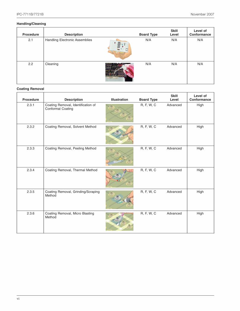
Handling/Cleaning
Procedure Description Board TypeSkillLevel
Level ofConformance
2.1 Handling Electronic Assemblies N/A N/A N/A
2.2 Cleaning N/A N/A N/A
Coating Removal
Procedure Description Illustration Board TypeSkillLevel
Level ofConformance
2.3.1 Coating Removal, Identification ofConformal Coating
R, F, W, C Advanced High
2.3.2 Coating Removal, Solvent Method R, F, W, C Advanced High
2.3.3 Coating Removal, Peeling Method R, F, W, C Advanced High
2.3.4 Coating Removal, Thermal Method R, F, W, C Advanced High
2.3.5 Coating Removal, Grinding/ScrapingMethod
R, F, W, C Advanced High
2.3.6 Coating Removal, Micro BlastingMethod
R, F, W, C Advanced High
IPC-7711B/7721B November 2007
vi
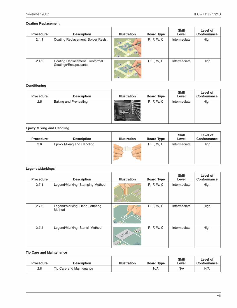
Coating Replacement
Procedure Description Illustration Board TypeSkillLevel
Level ofConformance
2.4.1 Coating Replacement, Solder Resist R, F, W, C Intermediate High
2.4.2 Coating Replacement, ConformalCoatings/Encapsulants
R, F, W, C Intermediate High
Conditioning
Procedure Description Illustration Board TypeSkillLevel
Level ofConformance
2.5 Baking and Preheating R, F, W, C Intermediate High
Epoxy Mixing and Handling
Procedure Description Illustration Board TypeSkillLevel
Level ofConformance
2.6 Epoxy Mixing and Handling R, F, W, C Intermediate High
Legends/Markings
Procedure Description Illustration Board TypeSkillLevel
Level ofConformance
2.7.1 Legend/Marking, Stamping Method R, F, W, C Intermediate High
2.7.2 Legend/Marking, Hand LetteringMethod
R, F, W, C Intermediate High
2.7.3 Legend/Marking, Stencil Method R, F, W, C Intermediate High
Tip Care and Maintenance
Procedure Description Illustration Board TypeSkillLevel
Level ofConformance
2.8 Tip Care and Maintenance N/A N/A N/A
November 2007 IPC-7711B/7721B
vii
Table of ContentsPART 2 Rework
3 Removal
3.1 Through-Hole Desoldering
Procedure DescriptionRound Lead
Board TypeSkillLevel
Level ofConformance
3.1.1 Continuous Vacuum Method R,F,W Intermediate High
3.1.2 Continuous Vacuum Method - Partial Clinch R,F,W Intermediate High
3.1.3 Continuous Vacuum Method - Full Clinch R,F,W Intermediate High
3.1.4 Full Clinch Straightening Method R,F,W Intermediate High
3.1.5 Full Clinch Wicking Method R,F,W Advanced High
3.2 PGA and Connector Removal
Procedure Description Board TypeSkillLevel
Level ofConformance
3.2.1 Solder Fountain Method R,F,W,C Expert Medium
3.3 Chip Component Removal
Procedure Description Board TypeSkillLevel
Level ofConformance
3.3.1 Bifurcated tip R,F,W,C Intermediate High
3.3.2 Tweezer Method R,F,W,C Intermediate High
3.3.3 Bottom Termination - Hot Air Method R,F,W,C Intermediate High
3.4 Leadless Component Removal
Procedure Description Board TypeSkillLevel
Level ofConformance
3.4.1 Solder Wrap Method R,F,W,C Advanced High
3.4.2 Flux Application Method R,F,W,C Advanced High
3.4.3 Hot Gas (Air) Reflow Method R,F,W,C Advanced High
IPC-7711B/7721B November 2007
viii
3.5 SOT Removal
Procedure Description Board TypeSkillLevel
Level ofConformance
3.5.1 Flux Application Method R,F,W,C Intermediate High
3.5.2 Flux Application Method - Tweezer R,F,W,C Intermediate High
3.5.3 Hot Air Pencil R,F,W,C Intermediate High
3.6 Gull Wing Removal (two sided)
Procedure Description Board TypeSkillLevel
Level ofConformance
3.6.1 Bridge Fill Method R,F,W,C Intermediate High
3.6.2 Solder Wrap Method R,F,W,C Intermediate High
3.6.3 Flux Application Method R,F,W,C Intermediate High
3.6.4 Bridge Fill Method - Tweezer R,F,W,C Advanced High
3.6.5 Solder Wrap Method - Tweezer R,F,W,C Advanced High
3.6.6 Flux Application Method - Tweezer R,F,W,C Advanced High
3.7 Gull Wing Removal (four sided)
Procedure Description Board TypeSkillLevel
Level ofConformance
3.7.1 Bridge Fill Method - Vacuum Cup R,F,W,C Advanced High
3.7.1.1 Bridge Fill Method - Surface Tension R,F,W,C Intermediate High
3.7.2 Solder Wrap Method - Vacuum Cup R,F,W,C Advanced High
3.7.2.1 Solder Wrap Method - Surface Tension R,F,W,C Intermediate High
3.7.3 Flux Application Method - Vacuum Cup R,F,W,C Advanced High
3.7.3.1 Flux Application Method - Surface Tension R,F,W,C Intermediate High
3.7.4 Bridge Fill Method - Tweezer R,F,W,C Advanced High
3.7.5 Solder Wrap Method - Tweezer R,F,W,C Advanced High
3.7.6 Flux Application Method - Tweezer R,F,W,C Advanced High
3.7.7 Hot Gas Reflow Method R,F,W,C Advanced High
November 2007 IPC-7711B/7721B
ix
3.8 J-Lead Removal
Procedure Description Board TypeSkillLevel
Level ofConformance
3.8.1 Bridge Fill Method - Tweezer R,F,W,C Advanced High
3.8.1.1 Bridge Fill Method - Surface Tension R,F,W,C Advanced High
3.8.2 Solder Wrap Method - Tweezer R,F,W,C Advanced High
3.8.2.1 Solder Wrap Method - Surface Tension R,F,W,C Advanced High
3.8.3 Flux Application Method - Tweezer R,F,W,C Advanced High
3.8.4 Flux & Tin Tip Only R,F,W,C Advanced High
3.8.5 Hot Gas Reflow System R,F,W,C Advanced High
3.9 BGA/CSP Removal
Procedure Description Board TypeSkillLevel
Level ofConformance
3.9.1 Hot Gas Reflow System R,F,W,C Advanced High
3.9.2 Vacuum Method R,F,W,C Advanced Medium
3.10 PLCC Socket Removal
Procedure Description Board TypeSkillLevel
Level ofConformance
3.10.1 Bridge Fill Method R,F,W,C Advanced High
3.10.2 Solder Wrap Method R,F,W,C Advanced High
3.10.3 Flux Application Method R,F,W,C Advanced High
3.10.4 Hot Air Pencil Method R,F,W,C Advanced Medium
4 Pad/Land Preparation
Procedure Description Board TypeSkillLevel
Level ofConformance
4.1.1 Surface Mount Land Preparation - Individual Method R,F,W,C Intermediate High
4.1.2 Surface Mount Land Preparation - Continuous Method R,F,W,C Intermediate High
4.1.3 Surface Solder Removal - Braid Method R,F,W,C Intermediate High
4.2.1 Pad Releveling - Using Blade Tip R,F,W,C Intermediate High
4.3.1 SMT Land Tinning - Using Blade Tip R,F,W,C Intermediate Medium
4.4.1 Cleaning SMT Lands - Using Blade Tip and Solder Braid R,F,W,C Intermediate High
IPC-7711B/7721B November 2007
x
5 Installation
5.1 Through-Hole Installation
Procedure Description
Install following the requirements of J-STD-001 andJ-HDBK-001
5.2 PGA and Connector Installation
Procedure Description Board TypeSkillLevel
Level ofConformance
5.2.1 Solder Fountain Method with PTH Prefilled R,F,W,C Expert Medium
5.3 Chip Installation
Procedure Description Board TypeSkillLevel
Level ofConformance
5.3.1 Solder Paste Method/Hot Air Pencil R,F,W,C Intermediate High
5.3.2 Point-to-Point Method R,F,W,C Intermediate High
5.4 Leadless Component Installation
Procedure Description Board TypeSkillLevel
Level ofConformance
5.4.1 Hot Gas (Air) Reflow Method R,F,W,C Advanced High
5.5 Gull Wing Installation
Procedure Description Board TypeSkillLevel
Level ofConformance
5.5.1 Multi-Lead Method - Top of Lead R,F,W,C Advanced High
5.5.2 Multi-Lead Method - Toe Tip R,F,W,C Advanced High
5.5.3 Point-to-Point Method R,F,W,C Intermediate High
5.5.4 Solder Paste Method/Hot Air Pencil R,F,W,C Advanced High
5.5.5 Hook Tip w/Wire Layover R,F,W,C Intermediate High
5.5.6 Blade Tip with Wire R,F,W,C Advanced Medium
November 2007 IPC-7711B/7721B
xi
5.6 J-Lead Installation
Procedure Description Board TypeSkillLevel
Level ofConformance
5.6.1 Solder Wire Method R,F,W,C Advanced High
5.6.2 Point-to-Point Method R,F,W,C Intermediate High
5.6.3 Solder Paste Method/Hot Air Pencil R,F,W,C Advanced High
5.6.4 Multi-Lead Method R,F,W,C Intermediate High
5.7 BGA/CSP Installation
Procedure Description Board Type Skill LevelLevel of
Conformance
5.7.1 Using Solder Wire to Prefill Lands R,F,W,C Advanced High
5.7.2 Using Solder Paste to Prefill Lands R,F,W,C Advanced High
5.7.3 BGA Reballing Procedure - Fixture Method R,C Advanced High
5.7.4 BGA Reballing Procedure - Paper Carrier Method R,C Advanced High
5.7.5 BGA Reballing Procedure - Polyimide Stencil Method R,C Advanced High
6 Removing Shorts
Procedure Description Board Type Skill LevelLevel of
Conformance
6.1.1 J-Leads - Draw Off Method R,F,W,C Intermediate High
6.1.2 J-Leads - Respread Method R,F,W,C Intermediate High
6.1.2.1 J-Leads - Braid Method R,F,W,C Intermediate High
6.1.3 Gull-Wing - Draw Off Method R,F,W,C Intermediate High
6.1.4 Gull-Wing - Respread Method R,F,W,C Intermediate High
6.1.4.1 Gull-Wing - Braid Method R,F,W,C Intermediate High
IPC-7711B/7721B November 2007
xii
Table of ContentsPART 3 Modification and Repair
Blisters and Delamination
Procedure Description Illustration Board TypeSkillLevel
Level ofConformance
3.1 Delamination/Blister Repair, InjectionMethod
R Advanced High
Bow & Twist
Procedure Description Illustration Board TypeSkillLevel
Level ofConformance
3.2 Bow and Twist Repair R, W Advanced Medium
Hole Repair
Procedure Description Illustration Board TypeSkillLevel
Level ofConformance
3.3.1 Hole Repair, Epoxy Method R, W Advanced High
3.3.2 Hole Repair,Transplant Method R. W Expert High
Key and Slot Repair
Procedure Description Illustration Board TypeSkillLevel
Level ofConformance
3.4.1 Key and Slot Repair, Epoxy Method R, W Advanced High
3.4.2 Key and Slot Repair, TransplantMethod
R, W Expert High
November 2007 IPC-7711B/7721B
xiii
Base Material Repair
Procedure Description Illustration Board TypeSkillLevel
Level ofConformance
3.5.1 Base Material Repair, Epoxy Method R, W Advanced High
3.5.2 Base Material Repair, Area TransplantMethod
R, W Expert High
3.5.3 Base Material Repair, EdgeTransplant Method
R, W Expert High
Lifted Conductors
Procedure Description Illustration Board TypeSkillLevel
Level ofConformance
4.1.1 Lifted Conductor Repair, Epoxy SealMethod
R, F Intermediate Medium
4.1.2 Lifted Conductor Repair, FilmAdhesive Method
R, F Intermediate High
IPC-7711B/7721B November 2007
xiv
Conductor Repair
Procedure Description Illustration Board TypeSkillLevel
Level ofConformance
4.2.1 Conductor Repair, Foil Jumper, EpoxyMethod
R, F, C Advanced Medium
4.2.2 Conductor Repair, Foil Jumper, FilmAdhesive Method
R, F, C Advanced High
4.2.3 Conductor Repair, Welding Method R, F, C Advanced High
4.2.4 Conductor Repair, Surface WireMethod
R, F, C Intermediate Medium
4.2.5 Conductor Repair, Through BoardWire Method
R Advanced Medium
4.2.6 Conductor Repair/Modification,Conductive Ink Method
R, F, C Expert Medium
4.2.7 Conductor Repair, Inner LayerMethod
R, F Expert High
Conductor Cut
Procedure Description Illustration Board TypeSkillLevel
Level ofConformance
4.3.1 Conductor Cut, Surface Conductors R, F Advanced High
4.3.2 Conductor Cut, Inner LayerConductors
R, F Advanced High
4.3.3 Deleting Inner Layer Connection at aPlated Hole, Drill Through Method
R, F Advanced High
4.3.4 Deleting Inner Layer Connection at aPlated Hole, Spoke Cut Method
R, F Advanced High
November 2007 IPC-7711B/7721B
xv
Lifted Land Repair
Procedure Description Illustration Board TypeSkillLevel
Level ofConformance
4.4.1 Lifted Land Repair, Epoxy Method R, F Advanced Medium
4.4.2 Lifted Land Repair, Film AdhesiveMethod
R, F Advanced Medium
Land Repair
Procedure Description Illustration Board TypeSkillLevel
Level ofConformance
4.5.1 Land Repair, Epoxy Method R, F Advanced Medium
4.5.2 Land Repair, Film Adhesive Method R, F Advanced High
Edge Contact Repair
Procedure Description Illustration Board TypeSkillLevel
Level ofConformance
4.6.1 Edge Contact Repair, Epoxy Method R, F, W, C Advanced Medium
4.6.2 Edge Contact Repair, Film AdhesiveMethod
R, F, W, C Advanced High
4.6.3 Edge Contact Repair, Plating Method R, F, W, C Advanced High
IPC-7711B/7721B November 2007
xvi
Surface Mount Pad Repair
Procedure Description Illustration Board TypeSkillLevel
Level ofConformance
4.7.1 Surface Mount Pad Repair, EpoxyMethod
R, F, C Advanced Medium
4.7.2 Surface Mount Pad Repair, FilmAdhesive Method
R, F, C Advanced High
4.7.3 Surface Mount, BGA Pad Repair,Film Adhesive Method
R, F, C Advanced High
Plated Hole Repair
Procedure Description Illustration Board TypeSkillLevel
Level ofConformance
5.1 Plated Hole Repair, No Inner LayerConnection
R, F, W Intermediate High
5.2 Plated Hole Repair, Double WallMethod
R, F, W Advanced Medium
5.3 Plated Hole Repair, Inner LayerConnection
R Expert Medium
5.4 Plated Hole Repair, No Inner LayerConnection, Clinched Jumper WireMethod
R,F,W Intermediate Medium
November 2007 IPC-7711B/7721B
xvii
Jumpers
Procedure Description Illustration Board TypeSkillLevel
Level ofConformance
6.1 Jumper Wires R, F, W, C Intermediate N/A
6.2.1 Jumper Wires, BGA Components, FoilJumper Method
R, F Expert Medium
6.2.2 Jumper Wires, BGA Components,Through Board Method
R, F Expert High
Component Additions
Procedure Description Illustration Board TypeSkillLevel
Level ofConformance
6.3 Component Modifications andAdditions
R, F, W, C Advanced N/A
Flexible Conductor Repair
Procedure Description Illustration Board TypeSkillLevel
Level ofConformance
7.1.1 Flexible Conductor Repair F Expert Medium
8 Wires
8.1 Splicing
Procedure Description Board Type Skill LevelLevel of
Conformance
8.1.1 Mesh Splice N/A Intermediate Low
8.1.2 Wrap Splice N/A Intermediate Low
8.1.3 Hook Splice N/A Intermediate Low
8.1.4 Lap Splice N/A Intermediate Low
IPC-7711B/7721B November 2007
xviii
General Information and Common Procedures
1 General
1.1 Scope This document covers procedures for repair-ing and reworking printed board assemblies. It is an aggre-gate of information collected, integrated and assembled bythe Repairability Subcommittee (7-34) of the ProductAssurance Committee of the IPC. This revision includesexpanded coverage for lead free processes, and additionalinspection guidelines for operations such as repair that maynot have other published criteria.
This document does not limit the maximum number ofrework, modification or repair actions to a Printed CircuitAssembly.
1.2 Purpose This document prescribes the proceduralrequirements, tools, materials and methods to be used inthe modification, rework, repair, overhaul or restoration ofelectronic products. Although this document is based inlarge part on the Product Class definitions used in IPCdocuments such as J-STD-001 or IPC-A-610, this docu-ment should be considered applicable to any type of elec-tronic equipment. When invoked by contract as the control-ling document for the modification, rework, repair,overhaul or restoration of products, the requirements flow-down apply.
IPC has identified the most common equipment and pro-cess in order to make a specific repair or rework. It is pos-sible that alternate equipment and processes can be used tomake the same repair. If alternate equipment is used, it isup to the user to determine that the resultant assembly isgood and undamaged.
1.2.1 Definition of Requirements This document isintended to be used as a guide and there are no specificrequirements or criteria unless separately and specificallycalled out in a user’s contractual or other documentation.When statements such as ‘‘must,’’ ‘‘should’’ or ‘‘need tobe’’ are used, they are stressing an important point. If thesestrong recommendations are not followed the end resultmay not be satisfactory and additional damage could becaused.
1.3 Background Today’s electronic assemblies are morecomplex and smaller than ever before. Despite this, theycan be successfully modified, reworked or repaired if theproper techniques are followed. This manual is designed tohelp users repair, rework and modify electronic assemblieswith minimum impact on end use function or reliability.The procedures in this document have been obtained fromassemblers, printed board manufacturers and users who
recognize the need for documenting commonly usedrework, repair and modification techniques. These tech-niques have, in general, been proven to be acceptable forthe class of product indicated through testing and extendedfield functionality. Procedures contained herein were sub-mitted for inclusion by commercial and military organiza-tions too numerous to list individually. The RepairabilitySubcommittee has, where appropriate, revised proceduresto reflect improvements.
1.4 Terms and Definitions Definitions marked with an *are from IPC-T-50 and apply to the use of this document.
PCA – Printed Circuit Assembly
*Rework – the act of reprocessing noncomplying articles,through the use of original or equivalent processing, in amanner that assures full compliance of the article withapplicable drawings or specifications.
*Modification – the revision of the functional capability ofa product in order to satisfy new acceptance criteria. Modi-fications are usually required to incorporate design changeswhich can be controlled by drawings, change orders, etc.Modifications should only be performed when specificallyauthorized and described in detail on controlled documen-tation.
*Repair – the act of restoring the functional capability of adefective article in a manner that does not assure compli-ance of the article with applicable drawings or specifica-tions.
1.4.1 Class of Product The user of the product isresponsible for identifying the Class of Product. The pro-cedure selected for action to be taken (modification,rework, repair, overhaul etc.) must be consistent with theClass identified by the user. The three Classes of Productare:
Class 1 – General Electronic ProductsIncludes products for applications where the major require-ment is the function of the completed assembly.
Class 2 – Dedicated Service Electronic ProductsIncludes products where continued performance andextended life is required, and for which uninterrupted ser-vice is desired but not critical. Typically, the end use envi-ronment would not cause failures.
Class 3 – High Performance Electronic ProductsIncludes products where continued performance orperformance-on-demand is critical. Equipment downtimecannot be tolerated, end-use environment may be uncom-monly harsh, and the equipment must function whererequired, such as life support and other critical systems.
November 2007 IPC-7711B/7721B
1