rexnord automatic deburring machine mid-term reportdbeale/mech4240-50/reports/... · rexnord...
TRANSCRIPT
Page 1 of 24
Rexnord Automatic Deburring Machine
Mid-Term Report
Corp 9 Project Group Paul Cofield Frank Orona Steven Rich
Spencer Reynolds Dr. Beale – Comprehensive Design One – MECH 4240 – Spring 2010
Page 2 of 24
ABSTRACT
This is a preliminary report for the Corp 9 project group. Included in this report is a
detailed description of the evolution of ideas and concepts. Rexnord is a company that requires
an automatic deburring system for a series of different parts. This deburring system must be
fully automatic and be able to adapt to different size of parts very quickly. Size is also a concern
as the entire system will need to fit inside of a tight machining cell.
Many concepts have been developed and evaluated. The first concept revolved around
the part having to be deburred, be flipped and then move into position on a conveyor where it
will be clamped by a chuck. Here, sanding disks powered by motors will turn on and translate
inward. The part would then rotate to fully debur all sides. The part would then be release from
the chuck and be kicked off by a pneumatic actuator. This concept is very thorough but overly
complex and expensive.
The design focused on by this report is a variation of the one above that includes
simplified steps and equipment. The part is to be conveyed into the machine where a magnetic
conveyor will pick it up from the top. Here the conveyor will translate the part through the
deburring process. This process contains a series of three radial axial brushes. After deburring is
complete, the part is released on an exit ramp for pick up.
The following writing will present the current design in great detail. Other designs will
also be addressed and laid out in some detail. All concepts that are presented are not permanent.
The intent of this preliminary evaluation is to inform the sponsor of the ongoing development of
the deburring system. Input and recommendations for changes are welcome and encouraged.
Page 3 of 24
TABLE OF CONTENTS
• Abstract………………………………………………………………………………...p.2
• Introduction ……………………………………………………………………………p.4
• Mission Objective……………….……………………………………………………...p.5
• Architectural Design Development……………………………………………….…..p.5
o Analysis of Feasible Alternatives…………………………………………….…p.5
o Product hierarchy………………………………………………………………..p.7
o Bill of Materials…………………………………………………………………p.9
o Requirements………………………………………………………………..…p.10
o Concept of Operations………………………...……………………………….p.11
o Validate and Verify………………………………………………………..…..p.13
o Interfaces and ICD……………………………………………………..……...p.13
o Mission Environment…………………………………………………….……p.14
o Technical Resource Budget Tracking…………………………………………p.14
o Risk Management………………………………………………………….…..p.15
o Configuration Management and Documentation………………………….…..p.15
• Subsystems Design Engineering…………………………………………………….p.16
• Project Management…………………………………………………………………p.18
• Conclusions……………………………….…………………………………………..p.19
• Appendix………………………………………………………………….…………..p.21
Page 4 of 24
INTRODUCTION
Rexnord is a company that has many manufacturing facilities worldwide. The facility
here in Auburn, Alabama produces power transmission couplings for a variety of applications
including aerospace and military products. The focus of this project is on the T-Hub parts and
the removal of machining burs.
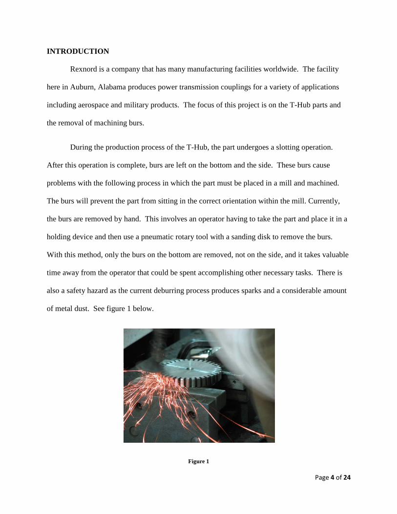
During the production process of the T-Hub, the part undergoes a slotting operation.
After this operation is complete, burs are left on the bottom and the side. These burs cause
problems with the following process in which the part must be placed in a mill and machined.
The burs will prevent the part from sitting in the correct orientation within the mill. Currently,
the burs are removed by hand. This involves an operator having to take the part and place it in a
holding device and then use a pneumatic rotary tool with a sanding disk to remove the burs.
With this method, only the burs on the bottom are removed, not on the side, and it takes valuable
time away from the operator that could be spent accomplishing other necessary tasks. There is
also a safety hazard as the current deburring process produces sparks and a considerable amount
of metal dust. See figure 1 below.
Figure 1
Page 5 of 24
The goal of this project is to produce a deburring machine that will be fully automatic
from beginning to end, collect all dust produced by the deburring process, debur both the bottom
and the top of the part, use a spark-less method of deburring, debur all shapes and sizes of
specified parts, leave the necessary finish on the part surfaces, and be quickly moved to other
cells within the facility. All these requirements must be met while beating the current time it
takes to debur the part.
MISSION OBJECTIVE
Our mission is to:
• Create an automated deburring and transport system while: o Reducing production time o Improving overall quality of the finished product o Improving the efficiency of the waste removal process
ARCHITECTURAL DESIGN AND DEVELOPMENT
Feasible Alternatives
Large Sanding Disc Design
Advantages
- One disc deburs entire part bottom - No rotation of part required - Cheapest of the possible design concepts - Only one rotary motor needed - Requires less space to operate
Disadvantages
- Cannot debur the sides of the part - Sanders wear out - Difficult to keep part in place on conveyor - Difficult to automatically load the part straight from slotter
Page 6 of 24
Center Holding with Rotation Design
Advantages
- Two sanders debur the bottom and the sides of the part - Provides a more thorough sanding of the part - Will give the part a more polished finish than that of the one large disc
Disadvantages
- Very difficult to auto-load from the conveyor - More expensive than the large single disc sander design - Difficult to rotate the part across the sanders - Difficult to lift the part off of the conveyor for the debur process - More moving parts for possible malfunctions - Sanders wear out
Magnetic Conveyor Design
Advantages
- Requires less moving parts/sensors - Can move directly from slotter conveyor to magnetic conveyor - Allows part to pass through powerful array of rotating brushes for optimum polish - Magnet can be cut off before the end of conveyor so part can drop off conveyor
automatically - No altercations to original conveyor is needed - Can be operated merely by an on/off switch
Disadvantages
- Deburred metal from parts could stick to the magnet, possibly causing difficulty in the efficiency of the vacuum cleanup system.
- Deburred metal stuck to magnet could cause build-ups which may send part through brushes at an angle
- More expensive than the other designs
Please observe the appendix for rough drawings of these alternative designs.
Page 7 of 24
Product Hierarchy
The total system is known as the Rexnord Deburring Machine. Below that, is the
hierarchy of the subsystems and components where, after breaking down the Rexnord Deburring
Machine, there are five main subsystems that stand out. The first is the entrance conveyor. This
subsystem carries the part from the slotter into the deburring machine. The second subsystem is
the inverted magnetic conveyor that lifts the part from the entrance conveyor and takes it into the
brushes. The third is the deburring system itself composed of a series of spinning wire brushes.
The next, and fourth, subsystem is the exit ramp where the part is removed from the magnetic
conveyor and then slides down the metal ramp where it awaits pick up for the next operation.
The fifth subsystem is the active vacuum motor that pulls in any dust created by the deburring
process.
The components that comprise these subsystems are as follows. For the entrance
conveyor, there will be a basic set up of an electric motor and a belt resting on rollers and is
supported by a simple metal structure. The conveyor is short, and may be tilted for the height
adjustment of differing parts. The entrance conveyor will also have a set of two centering rails
that can be adjusted for parts with differing diameters. The magnetic conveyor possesses the
same components as the entrance conveyor except that it has a magnetic layer underneath the
belt. This magnetic will capture the part and translate it through the deburring brushes and
release it at the exit ramp. Also note that the magnetic conveyor is inverted so the part can be
lifted from the top. The components for the deburring system consist of three radial coil brushes
that are filled with steel wire. These are powered by electric motors and will spin at a necessary
rpm to achieve the desired finish. The exit ramp is simply made from bent and formed sheet
metal supported by a basic structure. The dust collection subsystem is composed of a vacuum
Page 8 of 24
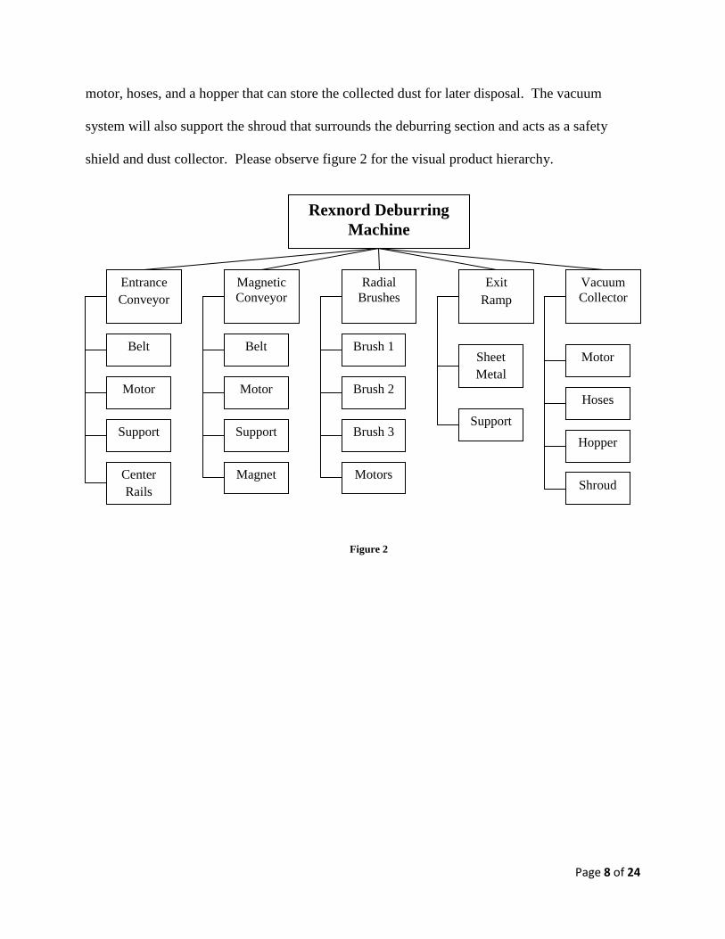
motor, hoses, and a hopper that can store the collected dust for later disposal. The vacuum
system will also support the shroud that surrounds the deburring section and acts as a safety
shield and dust collector. Please observe figure 2 for the visual product hierarchy.
Rexnord Deburring Machine
Entrance Conveyor
Magnetic Conveyor
Radial Brushes
Exit Ramp
Belt
Motor
Support
Belt
Motor
Support
Magnet
Brush 3
Brush 2
Brush 1 Sheet Metal
Support
Motor
Hoses
Hopper
Vacuum Collector
Motors Center Rails Shroud
Figure 2
Page 9 of 24
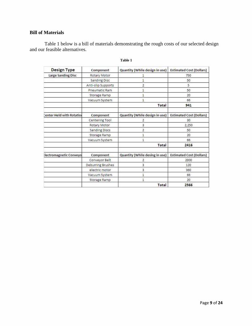
Bill of Materials Table 1 below is a bill of materials demonstrating the rough costs of our selected design and our feasible alternatives.
Table 1
Page 10 of 24
Requirements:
Rexnord Deburring System
• Debur the various sizes and shapes of the specified parts.
• Leave the necessary finish on the part surface.
• Fully automated from beginning requiring no aid from an operator.
• Automatic collection and removal of dust.
• No sparks must be generated during deburring process.
• Must debur the bottom and sides of each part.
• Must be free to quickly move to other cells.
• Deburring system must meet all OSHA safety and environmental standards for
operations.
Subsystem Level Requirements
� Entrance conveyor must be adjustable for height changes in parts.
� Magnetic conveyor must be strong enough to support weight of part and hold part
steady during the deburring process.
� Magnetic conveyor must also release part for delivery down the exit ramp.
� Exit ramp must be large enough to support two of the largest sized parts.
� Exit ramp must be adjustable for different sized parts.
� Radial deburring brushes must be stiff enough to remove burs but not damage the
finish or remove material to the point where the part is out of tolerance.
� Brushes cannot create sparks while deburring.
� Dust collection system must remove all dust produced by the deburring process and
store in a hopper for later removal.
Page 11 of 24
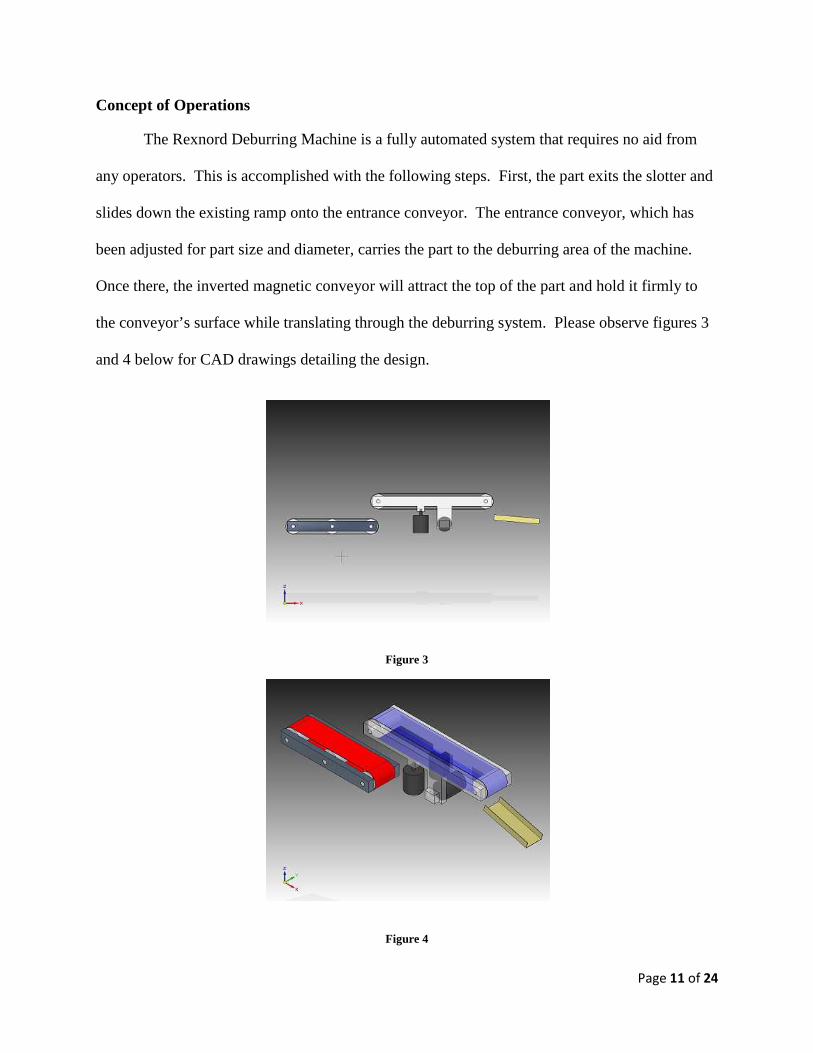
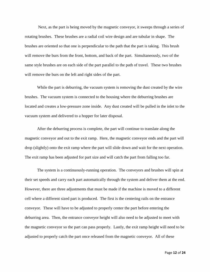
Concept of Operations
The Rexnord Deburring Machine is a fully automated system that requires no aid from
any operators. This is accomplished with the following steps. First, the part exits the slotter and
slides down the existing ramp onto the entrance conveyor. The entrance conveyor, which has
been adjusted for part size and diameter, carries the part to the deburring area of the machine.
Once there, the inverted magnetic conveyor will attract the top of the part and hold it firmly to
the conveyor’s surface while translating through the deburring system. Please observe figures 3
and 4 below for CAD drawings detailing the design.
Figure 3
Figure 4
Page 12 of 24
Next, as the part is being moved by the magnetic conveyor, it sweeps through a series of
rotating brushes. These brushes are a radial coil wire design and are tubular in shape. The
brushes are oriented so that one is perpendicular to the path that the part is taking. This brush
will remove the burs from the front, bottom, and back of the part. Simultaneously, two of the
same style brushes are on each side of the part parallel to the path of travel. These two brushes
will remove the burs on the left and right sides of the part.
While the part is deburring, the vacuum system is removing the dust created by the wire
brushes. The vacuum system is connected to the housing where the deburring brushes are
located and creates a low-pressure zone inside. Any dust created will be pulled in the inlet to the
vacuum system and delivered to a hopper for later disposal.
After the deburring process is complete, the part will continue to translate along the
magnetic conveyor and out to the exit ramp. Here, the magnetic conveyor ends and the part will
drop (slightly) onto the exit ramp where the part will slide down and wait for the next operation.
The exit ramp has been adjusted for part size and will catch the part from falling too far.
The system is a continuously-running operation. The conveyors and brushes will spin at
their set speeds and carry each part automatically through the system and deliver them at the end.
However, there are three adjustments that must be made if the machine is moved to a different
cell where a different sized part is produced. The first is the centering rails on the entrance
conveyor. These will have to be adjusted to properly center the part before entering the
deburring area. Then, the entrance conveyor height will also need to be adjusted to meet with
the magnetic conveyor so the part can pass properly. Lastly, the exit ramp height will need to be
adjusted to properly catch the part once released from the magnetic conveyor. All of these
Page 13 of 24
adjustments must be made only once prior to startup. Once completed, the machine will need no
adjustment until moved to another cell where a different part is produced. Located in the
appendix of this report are larger, more detailed CAD drawings of this design.
Validate and verification
Preliminary tests were done to guide the decision of the process to be used for bur
removal. Defective parts were acquired from the manufacturer, and several different tools were
used to debur the part, and the results were documented. When a final design is decided upon, a
more precise mock up of the process will be constructed for further testing and evaluation.
Interfaces and ICD
From the time of origin to that of completion, there will be several interfaces within our
automated deburring process. Our first interface will involve the process where the newly cut
part is ejected from the slotter and slides down onto the conveyor. At this point, there are no
problems concerning this interface since this process is already a part of the previous system.
The next interface will involve the part moving down the conveyor where it will then enter our
deburring machine and its magnetic conveyor. The magnetic conveyor will lift the part up onto
its moving body and firmly hold it in place. As the part moves along with the conveyor, it will
then pass through the rotating deburring brushes until it hits the last interface. At this interface,
the part will reach the end of the magnetic conveyor where it will drop off of the conveyor and
slide down to rest at the end of an inclined ramp.
Page 14 of 24
Mission Environment
The mission environment is a general manufacturing atmosphere. Indoors, air
conditioned and generally isolated from extreme hot or cold. The only factor that would
interfere with the process needed is a space constraint, and mobility of the machine. The
company requested that the deburer be easily moved by one person, as the process before the
deburring machine, the slotter, has to be accessible. The access door to change the tooling on the
slotter will be located behind the deburer. In addition to the mobility of the deburring machine,
it has to be able to fit in the space available within the cell.
Technical Resource Budget Tracking
� Volume – We expect the design of our machine to be 1.5 feet wide and have a length of 9
feet. The height will be adjustable and no taller than 4 feet. From these external
dimensions the overall volume of our deburring machine should be 54 cubic feet.
� Weight – Our design should weigh a light few hundred pounds but will have the
capability to be moved by the use of casters on the vertical support legs. These casters
should allow for easy mobility of our final design.
� Power – The automated deburring machine will be powered from a conventional 120
Volt, 60 Hertz cycle. All of the motors will be electrically powered as will be the
magnetic conveyor belt. This use of a standard 120 Volt power source will greatly
enhance the ease of use of our deburring machine and make it quite versatile.
Page 15 of 24
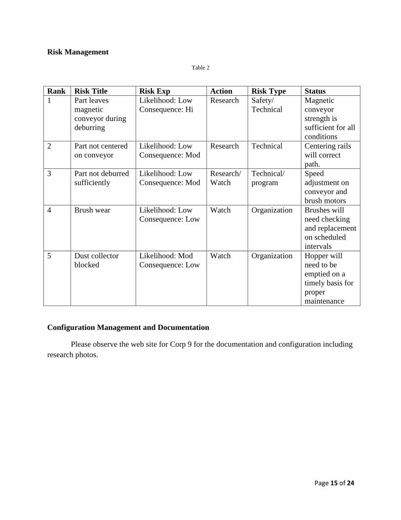
Risk Management
Table 2
Configuration Management and Documentation
Please observe the web site for Corp 9 for the documentation and configuration including research photos.
Rank Risk Title Risk Exp Action Risk Type Status 1 Part leaves
magnetic conveyor during deburring
Likelihood: Low Consequence: Hi
Research Safety/ Technical
Magnetic conveyor strength is sufficient for all conditions
2 Part not centered on conveyor
Likelihood: Low Consequence: Mod
Research Technical Centering rails will correct path.
3 Part not deburred sufficiently
Likelihood: Low Consequence: Mod
Research/ Watch
Technical/ program
Speed adjustment on conveyor and brush motors
4 Brush wear Likelihood: Low Consequence: Low
Watch Organization Brushes will need checking and replacement on scheduled intervals
5 Dust collector blocked
Likelihood: Mod Consequence: Low
Watch Organization Hopper will need to be emptied on a timely basis for proper maintenance
Page 16 of 24
SUBSYSTEMS DESIGN ENGINEERING
As the requirements become more and more specific, each subsystem has undergone an
evolutionary process since the first conception back in January. Starting in pre-phase A of the
engineering design process, each subsystem was thought of as an independent project in itself.
From here, the interfaces for each were established and an understanding of the system as a
whole was developed. This led into phase A with the concept studies. Part of the goal in this
phase was to conduct preliminary tests to help orient the design progress in the correct direction.
One experiment conducted was on a series of reject parts from Rexnord. These parts were one of
the styles that the machine is required to debur. The test conducted was to see which deburring
method was the most effective. Methods such as sanding, grinding, and wire wheel actions were
tried yielding some very interesting results.
The results from the preliminary experiment allowed the development to move into phase
B of the engineering design process. Here interviews were held with the Rexnord
representatives and ideas were suggested and discussed. A single design now could be focused
on and evaluated for development.
Starting with the entrance conveyor, the difficult task with this subsystem was to find a
way to orient the part correctly. In the previous designs, it had to have the part flip or be picked
up, but eventually it was determined that the part only has to be centered and conveyed up to the
magnetic conveyor where it can be picked up automatically.
For the magnetic conveyor, the initial design was to have an electro magnet activate and
then translate the part through the deburring system and then drop the part off. However, a
Page 17 of 24
simpler design utilizing the same principles was discovered by using a continuously running
magnetic conveyor.
The deburring system was the most challenging to develop. Our preliminary tests helped
us to narrow down our options until we decided upon the radial axial brushes. These brushes
will be made of carbon steel and are specifically designed to debur tough, resilient parts.
The exit ramp is a very basic idea that changed very little from the initial concept. At
first it was thought that an exit conveyor was needed. But after further evaluation, it was decided
that a simple ramp for transport and storage is the best idea for the job.
The vacuum system was a challenging subsystem to tackle. At first it was believed that a
passive, or gravity fed idea was suitable. But later requirements indicated that a more aggressive
system was needed. That is why an active vacuum motor is now used to pull the dust away from
the deburring system and storing it in a hopper for later disposal.
Page 18 of 24
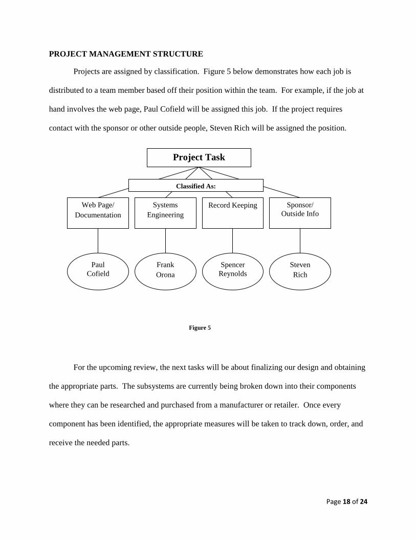
PROJECT MANAGEMENT STRUCTURE
Projects are assigned by classification. Figure 5 below demonstrates how each job is
distributed to a team member based off their position within the team. For example, if the job at
hand involves the web page, Paul Cofield will be assigned this job. If the project requires
contact with the sponsor or other outside people, Steven Rich will be assigned the position.
For the upcoming review, the next tasks will be about finalizing our design and obtaining
the appropriate parts. The subsystems are currently being broken down into their components
where they can be researched and purchased from a manufacturer or retailer. Once every
component has been identified, the appropriate measures will be taken to track down, order, and
receive the needed parts.
Project Task
Web Page/ Documentation
Systems Engineering
Record Keeping Sponsor/ Outside Info
Paul Cofield
Frank Orona
Spencer Reynolds
Steven Rich
Classified As:
Figure 5
Page 19 of 24
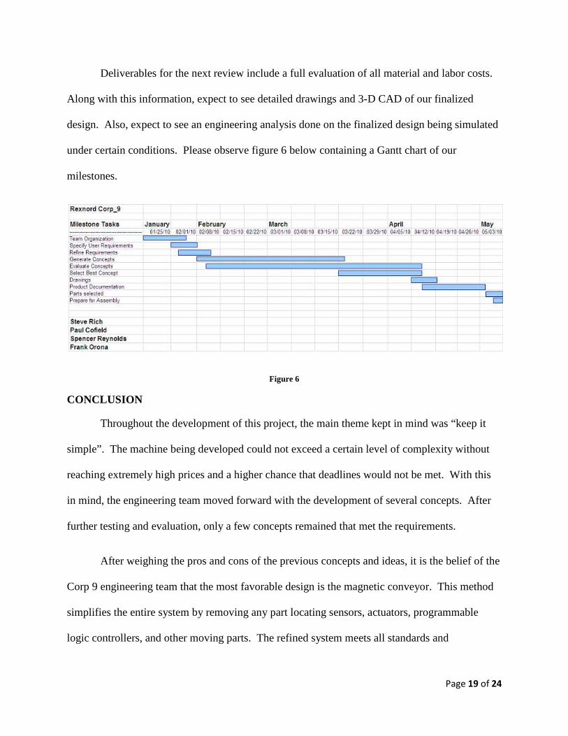
Deliverables for the next review include a full evaluation of all material and labor costs.
Along with this information, expect to see detailed drawings and 3-D CAD of our finalized
design. Also, expect to see an engineering analysis done on the finalized design being simulated
under certain conditions. Please observe figure 6 below containing a Gantt chart of our
milestones.
Figure 6
CONCLUSION
Throughout the development of this project, the main theme kept in mind was “keep it
simple”. The machine being developed could not exceed a certain level of complexity without
reaching extremely high prices and a higher chance that deadlines would not be met. With this
in mind, the engineering team moved forward with the development of several concepts. After
further testing and evaluation, only a few concepts remained that met the requirements.
After weighing the pros and cons of the previous concepts and ideas, it is the belief of the
Corp 9 engineering team that the most favorable design is the magnetic conveyor. This method
simplifies the entire system by removing any part locating sensors, actuators, programmable
logic controllers, and other moving parts. The refined system meets all standards and

Page 20 of 24
requirements, it will also be lighter, cheaper, smaller, continuously running, and the maintenance
will be simple. This design also will not generate sparks and will minimize the dust produced
during the deburring process. Please refer to the “Concept of Operations” section for more
details on function.
Page 21 of 24
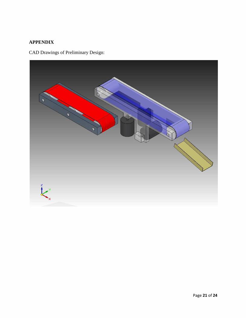
APPENDIX
CAD Drawings of Preliminary Design:
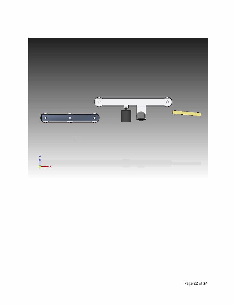
Page 22 of 24
Page 23 of 24
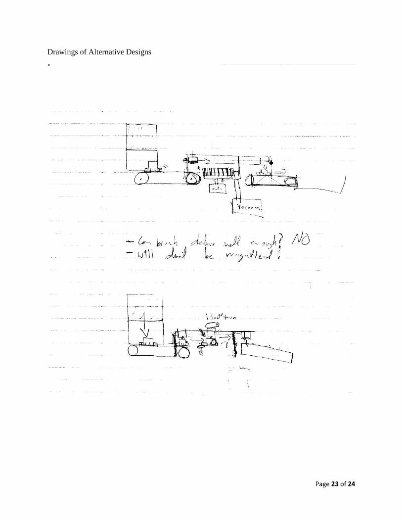
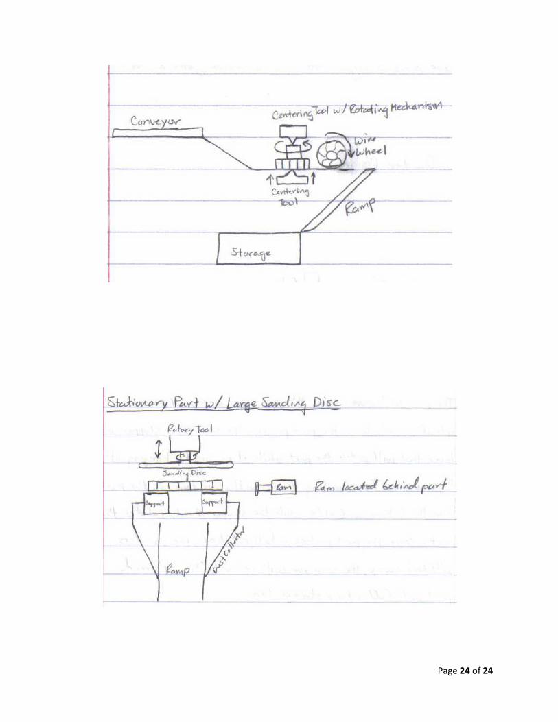
Drawings of Alternative Designs
Page 24 of 24