rexroth · pdf filerexroth indracontrol vcp 20 industrial hydraulics electric drives and...
TRANSCRIPT
Rexroth IndraControl VCP 20
IndustrialHydraulics
Electric Drivesand Controls
Linear Motion and Assembly Technologies Pneumatics
ServiceAutomation
MobileHydraulics
Rexroth MTC 200/ISP 200/MTA 200Teleservice
R911294748Edition 02
Application Manual
About this Documentation Teleservice
DOK-CONTRL-TELESER*V02-AW02-EN-P
Rexroth
MTC 200/ISP 200/MTA 200
Teleservice
Application Manual
DOK-CONTRL-TELESER*V02-AW02-EN-P
Document Number 120-0400-B390-02/EN
With the SYSTEM200 control, a system preparing for Teleservice isdelivered with which the BRC Teleservice software can be installed witha low effort.
This documentation refers to the customer who requires a fast installationoverview for Teleservice and also to the experienced systemadministrator who requires a technical overview of mechanism,installation, and configuration of the single system components.
Description ReleaseDate
Notes
120-0400-B390-01/EN 10.2002 First issue
120-0400-B390-02/EN 03.2005 Various changes
2002 Bosch Rexroth AG
Copying this document, giving it to others and the use or communicationof the contents thereof without express authority, are forbidden. Offendersare liable for the payment of damages. All rights are reserved in the eventof the grant of a patent or the registration of a utility model or design(DIN 34-1).
The specified data is for product description purposes only and may notbe deemed to be guaranteed unless expressly confirmed in the contract.All rights are reserved with respect to the content of this documentationand the availability of the product.
Bosch Rexroth AGBgm.-Dr.-Nebel-Str. 2 • D-97816 Lohr a. Main
Telephone +49 (0)93 52/40-0 • Tx 68 94 21 • Fax +49 (0)93 52/40-48 85
http://www.boschrexroth.com/
Dept. BRC/ESS (WS)
This document has been printed on chlorine-free bleached paper.
Title
Type of Documentation
Document Typecode
Internal File Reference
Purpose of Documentation
Record of Revisions
Copyright
Validity
Published by
Note
Teleservice Contents I
DOK-CONTRL-TELESER*V02-AW02-EN-P
Contents
1 Preface 1-1
2 Introduction 2-1
2.1 Overview of Teleservice ............................................................................................................... 2-1
2.2 Teleservice Features .................................................................................................................... 2-2
2.3 Definition of Terms........................................................................................................................ 2-2
2.4 Exclusions..................................................................................................................................... 2-3
3 System Requirements 3-1
3.1 Hardware ...................................................................................................................................... 3-1
Control PC (SYSTEM200)....................................................................................................... 3-1
Modem..................................................................................................................................... 3-1
Cable Connection .................................................................................................................... 3-2
3.2 Software........................................................................................................................................ 3-3
4 Teleservice Installation 4-1
4.1 Installing the Software .................................................................................................................. 4-1
4.2 Adjusting the System Settings...................................................................................................... 4-2
5 Running a Teleservice Session 5-1
5.1 Conditions..................................................................................................................................... 5-1
Connecting Remotely .............................................................................................................. 5-1
6 Behavior during a Teleservice Session / Notes on Possible Dangers 6-1
6.1 Tips on Procedure ........................................................................................................................ 6-1
6.2 Notes on Possible Dangers .......................................................................................................... 6-1
7 Installing a Modem 7-1
8 Installing a Remote Communications Network (RAS) 8-1
8.1 General Notes............................................................................................................................... 8-1
8.2 Activate RAS on the Control PC................................................................................................... 8-2
Configuration of RAS on the Control PC ................................................................................. 8-2
9 Appendix A: Troubleshooting 9-1
10 Appendix B: Limitations in DOS Mode 10-1
General Information............................................................................................................... 10-1
II Contents Teleservice
DOK-CONTRL-TELESER*V02-AW02-EN-P
DOS Full-Screen Mode ......................................................................................................... 10-1
DOS Graphics Window.......................................................................................................... 10-1
Graphic User Interface (GUI)................................................................................................. 10-2
PLC GUI (up to and including V19) ....................................................................................... 10-2
11 Appendix C: Configuring a Teleservice Session 11-1
General Information............................................................................................................... 11-1
Overview of Configuration ..................................................................................................... 11-1
Overview of Parameters ........................................................................................................ 11-2
Configuration / Important Parameters ................................................................................... 11-3
Tab: Transport ....................................................................................................................... 11-3
Tab: User ............................................................................................................................... 11-4
Tab: Security.......................................................................................................................... 11-4
Tab: Remote Control ............................................................................................................. 11-5
Tab: Options .......................................................................................................................... 11-5
Tab: File Transfer .................................................................................................................. 11-6
Tab: Customise ..................................................................................................................... 11-6
Tab: Dialin Bridge .................................................................................................................. 11-7
Tab: Audio ............................................................................................................................. 11-7
Tab: Protect Configuration..................................................................................................... 11-8
Tab: WEB Extension ............................................................................................................. 11-8
Tab: Client Connect............................................................................................................... 11-9
12 Service & Support 12-1
12.1 Helpdesk..................................................................................................................................... 12-1
12.2 Service-Hotline ........................................................................................................................... 12-1
12.3 Internet........................................................................................................................................ 12-1
12.4 Vor der Kontaktaufnahme... - Before contacting us... ................................................................ 12-1
12.5 Kundenbetreuungsstellen - Sales & Service Facilities ............................................................... 12-2
Teleservice Preface 1-1
DOK-CONTRL-TELESER*V02-AW02-EN-P
1 PrefaceA system prepared for Teleservice is delivered with the SYSTEM200control. This allows you to install the Rexroth Teleservice Software with aminimum of effort. All system components for remote data transfer (RDT),such as RAS or a standard modem, are already preinstalled on thesystem.
This manual is aimed both at customers who require a fast overview ofthe installation of Teleservice as well as experienced systemadministrators who require a technical overview of the method ofoperation, installation and configuration of the individual systemcomponents.
Depending on the information required by the user, you should proceedas follows when working with this manual:
Please read the following chapters:
Chapter: 2 Introduction
Chapter: 3 System Requirements
Chapter: 4 Teleservice Installation
Chapter: 5 Running a Teleservice Session
Chapter: 6 Behavior during a Teleservice Session / Notes on PossibleDangers
Please read the following chapters:
Chapter: 2 Introduction
Chapter: 3 System Requirements
Chapter: 7 Installing a Modem
Chapter: 8 Installing a Remote Communications Network (RAS)
Chapter: 4 Teleservice Installation
Chapter: 5 Running a Teleservice Session
Chapter: 6 Behavior during a Teleservice Session / Notes on PossibleDangers
Teleservice Installation on aRexroth SYSTEM200 Control
Teleservice Installation on aThird-Party PC (Control)
1-2 Preface Teleservice
DOK-CONTRL-TELESER*V02-AW02-EN-P
Teleservice Introduction 2-1
DOK-CONTRL-TELESER*V02-AW02-EN-P
2 Introduction
2.1 Overview of Teleservice
New possibilities in modern information and communication technologyare causing a change of structure within the industry in the field ofcustomer service.
By using teleservice, you can access, diagnose and maintain remotelylocated computers – all from your location at the company. In addition to asubstantial reduction in costs, this also results in an improvement inservice efficiency; this in turn is of benefit both to manufacturers and tooperators.
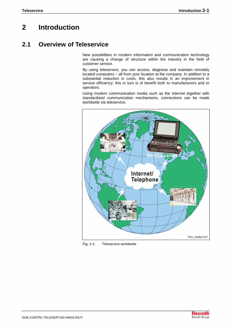
Using modern communication media such as the Internet together withstandardized communication mechanisms, connections can be madeworldwide via teleservice.
����������������
��� ����������
TSrv_Globe.FH7
Fig. 2-1: Teleservice worldwide

2-2 Introduction Teleservice
DOK-CONTRL-TELESER*V02-AW02-EN-P
2.2 Teleservice Features
There is a powerful program for the remote control of PC systems for theSYSTEM200. The system has the following features
• integrated WEB server on the control unit
• remote control via WEB browser per ActiveX Control (no clientinstallation required!)
• high speed by means of data compression
• Delta file transfer with split screen and drag-and-drop
• file synchronization
• system snapshot
• audio support
• record/playback function for logging
• powerful script language for automated processes
• configurable security levels
2.3 Definition of Terms
The PC from which the connection to the control unit to be monitored isestablished is termed the service PC. The screen content of the controlunit is displayed in parallel on the screen of the service PC during ateleservice session. The control unit can be monitored and/or operatedfrom the service PC.
Modulator/DemodulatorCommunication device for transmitting information via the telephonenetwork. A modem converts (modulates) digital data into analog signalsfor transmission via telephone lines. These signals are reconverted(demodulated) into digital signals at the other end of the line. Modemscan transmit data with various speeds or transmission rates.
Local Area NetworkA spatially limited network. In practice, spatially limited usually means abuilding or part of a building (floor) that is under the control of the owner.
Wide Area NetworkWANs consist of several LANs that are connected to each other viaremote lines. Such connections can be established, e.g. by dial-upconnections, ISDN, X.25 or a great variety of dedicated lines.
Dynamic Host Configuration Protocol ServerA protocol for dynamically assigning IP addresses within the LAN. Eachclient computer within the network is configured in such a way that itdraws its IP address from the DHCP server when the system starts up.Furthermore, additional address information (IP address of the WINSserver, etc.) is distributed to the clients by the DHCP server.
Service PC
Modem
LAN
WAN
DHCP Server
Teleservice Introduction 2-3
DOK-CONTRL-TELESER*V02-AW02-EN-P
Integrated Services Digital NetworkWhile conventional telephone networks are based on analog datatransmission, the ISDN standard is widely available in many countries inEurope. ISDN is based on digital data transmission and permits a higherdata transmission rate of 64 kbaud, as well as various special services.
Remote Data Communication NetworkRefers to a modem connection established between two computers viathe telephone network.
Remote Access ServiceA term used by Microsoft for the provision of dial-up services withinWindows operating systems. The NetBEUI, IPX/SPX and TCP/IPprotocols are supported.
Transmission Control Protocol/Internet ProtocolA protocol family originally developed for UNIX; now available for almostall operating systems. The entire Internet is based on TCP/IP. Eachcomputer in the network receives a unique address – the IP address.Important TCP/IP application protocols in the Internet are HTTP, FTP andDNS, among others.
Internetwork Packet Exchange/Sequenced Packet ExchangeA data transmission standard defined by Novell for the relaying andtransport layer of the ISO/OSI communication model. IPX/SPX is thestandard Novell protocol and is not compatible to TCP/IP.
Network Basic Input/Output SystemNetBIOS was developed in 1984 by IBM and is a programming interfacefor network programming. NetBIOS functions within the layer of thesession and communicates at the transport level with NetBEUI or TCP.
NetBIOS Extended User InterfaceA fast, nonrouting transport protocol developed by IBM for smallnetworks. NetBEUI communicates with NETBIOS at the session level.
2.4 Exclusions
The statements made in this description are purely for informationpurposes. They have been made to the best of our current knowledge.However, we cannot accept any liability arising from them. Furthermore,we explicitly point out that at the current state of technology it is notpossible to exclude errors in production under all application conditions,especially regarding software programs. Especially when used incombination with other products, particularly those from third-partymanufacturers where we have had no influence on the design, situationscould arise that result in the faulty functioning of individual products or of asystem.
ISDN
RDC Network
RAS
TCP/IP Protocol
IPX/SPX Protocol
NetBIOS
NetBEUI Protocol
2-4 Introduction Teleservice
DOK-CONTRL-TELESER*V02-AW02-EN-P
Teleservice System Requirements 3-1
DOK-CONTRL-TELESER*V02-AW02-EN-P
3 System Requirements
3.1 Hardware
Control PC (SYSTEM200)The following requirements must be fulfilled by Control PCs:
• IBM PC/AT or compatible system; recommended ≥ 80486DX2/66
• Operating system: NT 4.0 (Intel) with Service Pack 5 or Windows2000 with Service Pack 4
• min. RAM 32 MB
• min. free space on hard drive 16 MB
• CD-ROM drive for installing the software
• a free V24/RS232 (COM) interface for connecting an external modem
• or an ISDN board
• Teleservice within a LAN: The computer must be connected to theLAN by a network adapter. To select or configure the network adapter,please contact your network administrator. The NetBEUI, IPX/SPX orTCP/IP protocol is supported as the transmission protocol.
Note: Since the COM2 interface represents an equipment option forvarious control units, you must check before installing whetherthere is an available V24/RS232 interface on the machineoperating terminal.
ModemA modem allows the control PC and the remote PC to be controlled via atelephone line. One modem is required by each participant during aTeleservice session. The modem must be suitable for the WindowsNT4.0 respectively Windows 2000 OS. A list of modems that have beentested is contained in the software documentation.
A 'Hayes compatible' modem with a transmission speed of at least 33.6kbaud is recommended. Such a modem is laid out for the Hayescommand set, which represents the currently valid communicationstandard for modems. Analog modems with transmission rates of 28.8 -56 kbaud are currently available on the market.
ISDN data transmission is either via an external ISDN adapter connectedto the serial port or via an internal ISDN board slotted into a free ISA orPCI slot on the main board of the PC.
If both analog and digital data is to be transmitted, we recommend acombi device consisting of an analog modem and an ISDN adapter withan automatic switchover.
Analog Modem
ISDN
Combi Device for Analog andISDN Operation
3-2 System Requirements Teleservice
DOK-CONTRL-TELESER*V02-AW02-EN-P
Positive results have been gained using the following modem makes andtypes:
External modem: 33.6 kBaud, analog 1&1/ Creatix Modem Skyconnect
External modem: 56 kBaud, analog ELSA MicroLink 56k Internet
(Germany, Europe, UK, USA)
External modem: ISDN ELSA MicroLink ISDN Internet
(Germany, Europe, UK)
Note: The same type of modem must be used on both ends of thetransmission path (analog/analog or ISDN/ISDN).
The decision as to which type of modem is to be used also depends onthe final location of the system or the machine. Not only power suppliesand supply voltages can differ from country to country. In addition, not allstandards, such as ISDN, are supported throughout the world. The localconditions must therefore always be checked by the machinemanufacturer.
Cable Connection
To connect a PC to an external modem, you require a V24/RS232standard null modem cable. The length of this connection must notexceed 15 meters, as defined by the V24/RS232 specification.
If you are using an internal modem instead of an external modem, thenthis connection is not required, since the modem is slotted directly ontothe ISA/PCI bus of the PC and communicates with the PC via thisconnection.
Note: Additional information is contained in the documentation of themodem manufacturer.
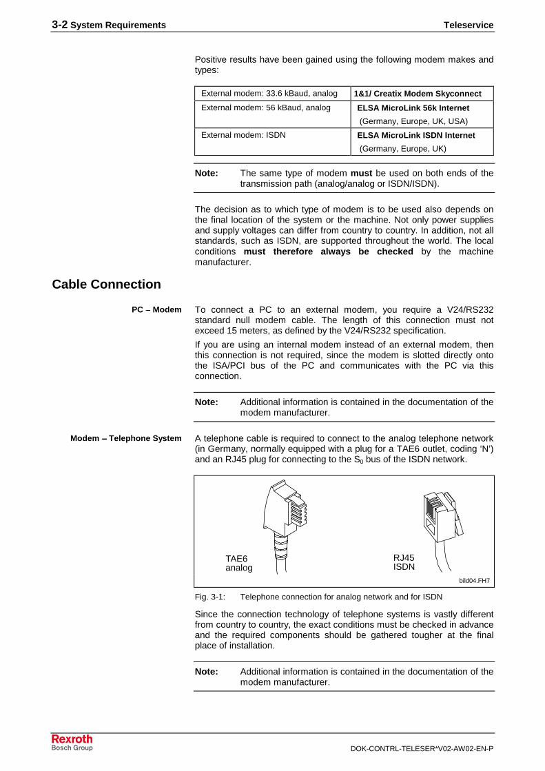
A telephone cable is required to connect to the analog telephone network(in Germany, normally equipped with a plug for a TAE6 outlet, coding ‘N’)and an RJ45 plug for connecting to the S0 bus of the ISDN network.
TAE6analog
RJ45ISDN
bild04.FH7
Fig. 3-1: Telephone connection for analog network and for ISDN
Since the connection technology of telephone systems is vastly differentfrom country to country, the exact conditions must be checked in advanceand the required components should be gathered tougher at the finalplace of installation.
Note: Additional information is contained in the documentation of themodem manufacturer.
PC →→→→ Modem
Modem →→→→ Telephone System

Teleservice System Requirements 3-3
DOK-CONTRL-TELESER*V02-AW02-EN-P
3.2 Software
To run a Teleservice session between a SYSTEM200 and a service PC,you require NetSupport Manager® Remote Control Software, VersionV6.11.
Note: With Version V6.11, NetSupport Manager® provides platform-wide support for DOS, Windows, OS/2, Windows 95, WfWand Windows NT/Windows 2000 servers and NTworkstations.
All parts of this software are subject to a license contract and may only beused in conjunction with the license agreement. Each license allows toinstal and use the client application of the software at a control PC.
The NetSupport Manager® software package consists of two mainapplications:
• The Control application. The control application is installed on theservice PC and allows other PCs to be monitored and controlled.
Note: The control application is not a part of teleservice package forSYSTEM200. Please contact you BRC sales department incase of need!
• The Client application. The client application is installed on theSYSTEM200 and allows a service PC to remotely access this controlunit.
When installing and configuring the software, observe the instructionscontained in the software manuals (delivered with the product).
Also observe example configurations of the software contained in thismanual.
3-4 System Requirements Teleservice
DOK-CONTRL-TELESER*V02-AW02-EN-P
Teleservice Teleservice Installation 4-1
DOK-CONTRL-TELESER*V02-AW02-EN-P
4 Teleservice Installation
4.1 Installing the Software
BRC_Installation_1.bmp
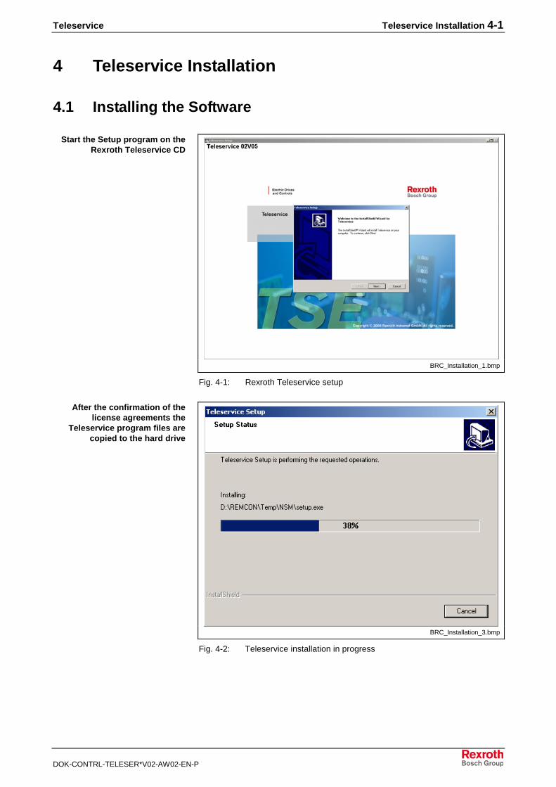
Fig. 4-1: Rexroth Teleservice setup
BRC_Installation_3.bmp
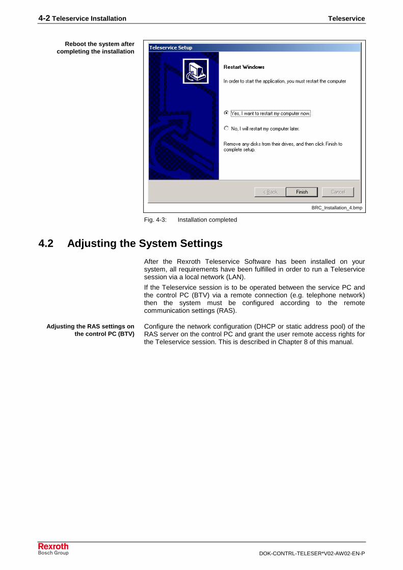
Fig. 4-2: Teleservice installation in progress
Start the Setup program on theRexroth Teleservice CD
After the confirmation of thelicense agreements the
Teleservice program files arecopied to the hard drive
4-2 Teleservice Installation Teleservice
DOK-CONTRL-TELESER*V02-AW02-EN-P
BRC_Installation_4.bmp
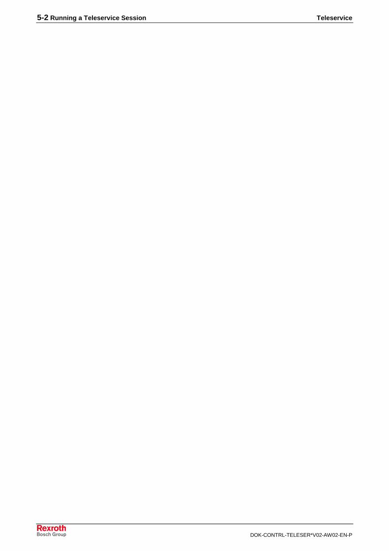
Fig. 4-3: Installation completed
4.2 Adjusting the System Settings
After the Rexroth Teleservice Software has been installed on yoursystem, all requirements have been fulfilled in order to run a Teleservicesession via a local network (LAN).
If the Teleservice session is to be operated between the service PC andthe control PC (BTV) via a remote connection (e.g. telephone network)then the system must be configured according to the remotecommunication settings (RAS).
Configure the network configuration (DHCP or static address pool) of theRAS server on the control PC and grant the user remote access rights forthe Teleservice session. This is described in Chapter 8 of this manual.
Reboot the system aftercompleting the installation
Adjusting the RAS settings onthe control PC (BTV)

Teleservice Running a Teleservice Session 5-1
DOK-CONTRL-TELESER*V02-AW02-EN-P
5 Running a Teleservice Session
5.1 Conditions
Before a Teleservice session can successfully be run, the two computersthat are to communicate with each other must be correctly configured.
Connecting RemotelyWhen running a remote diagnosis via a remote communication network,the following requirements must be met before starting the NSM software:
• A modem must be installed on both computers
• The connection to the telephone network via modem must already beestablished for both computers
• The service PC must be configured as the RAS client and must have avalid telephone book entry for dialing up the RAS server
• The control unit must be configured as the RAS server. The plannedcallback must be set on the telephone number of the service PC
• A valid user account for Teleservice, together with all required accessrights, must be planned on the RAS server
• Before starting the Teleservice session, the RAS connection betweenboth computers must be already established. To do this, proceed asfollows:
• Start the remote communication network on the service PC fromthe My Computer file. Select the telephone book entry for thecontrol unit to be dialed up and then start dialing.
• The connection to the RAS server is established; you will beprompted on the service PC to enter your user data.
• The RAS server then terminates the connection to the service PCand prepares the callback.
• After callback has been completed, the RAS connection has nowbeen established between the control PC and the service PC.
• In the following step, you can start the Teleservice session via theNetSupport control application respectively via the Web interface.
Note: A detailled description of how to execute a teleservice sessionyou will find within the documentation of the BRC teleservicesoftware I-Remote. The control application is not part of theTeleservice SYSTEM200 package. Please contact your BRCsales department in case of need.
Note: If the Teleservice session is to be run within the LAN, thenNetSupport Manager can be started immediately. A remotedata communication connection is not required for this.
5-2 Running a Teleservice Session Teleservice
DOK-CONTRL-TELESER*V02-AW02-EN-P
Teleservice Behavior during a Teleservice Session / Notes on Possible Dangers 6-1
DOK-CONTRL-TELESER*V02-AW02-EN-P
6 Behavior during a Teleservice Session / Notes onPossible Dangers
6.1 Tips on Procedure
During the entire session, keep in contact by telephone with a trainedservice technician located at the machine. Comment on importantoperating steps and/or have these confirmed so that you are alsoinformed by telephone at all times on the condition of the system. Onlytake any action after prior consultation.
Note: Hold strictly to this procedure and be aware that the machinemay take direct action based on your operating steps.
Carry out all operating steps slowly and after due consideration. Pleaseobserve that remote control by the service PC is normally via the remotedata communication network and, for this reason, the system may beoperated with a slight delay.
6.2 Notes on Possible Dangers
WARNING
Unsupervised machine movements triggered byremote operation can result in injuries topersonnel and damage to materials!

6-2 Behavior during a Teleservice Session / Notes on Possible Dangers Teleservice
DOK-CONTRL-TELESER*V02-AW02-EN-P
Teleservice Installing a Modem 7-1
DOK-CONTRL-TELESER*V02-AW02-EN-P
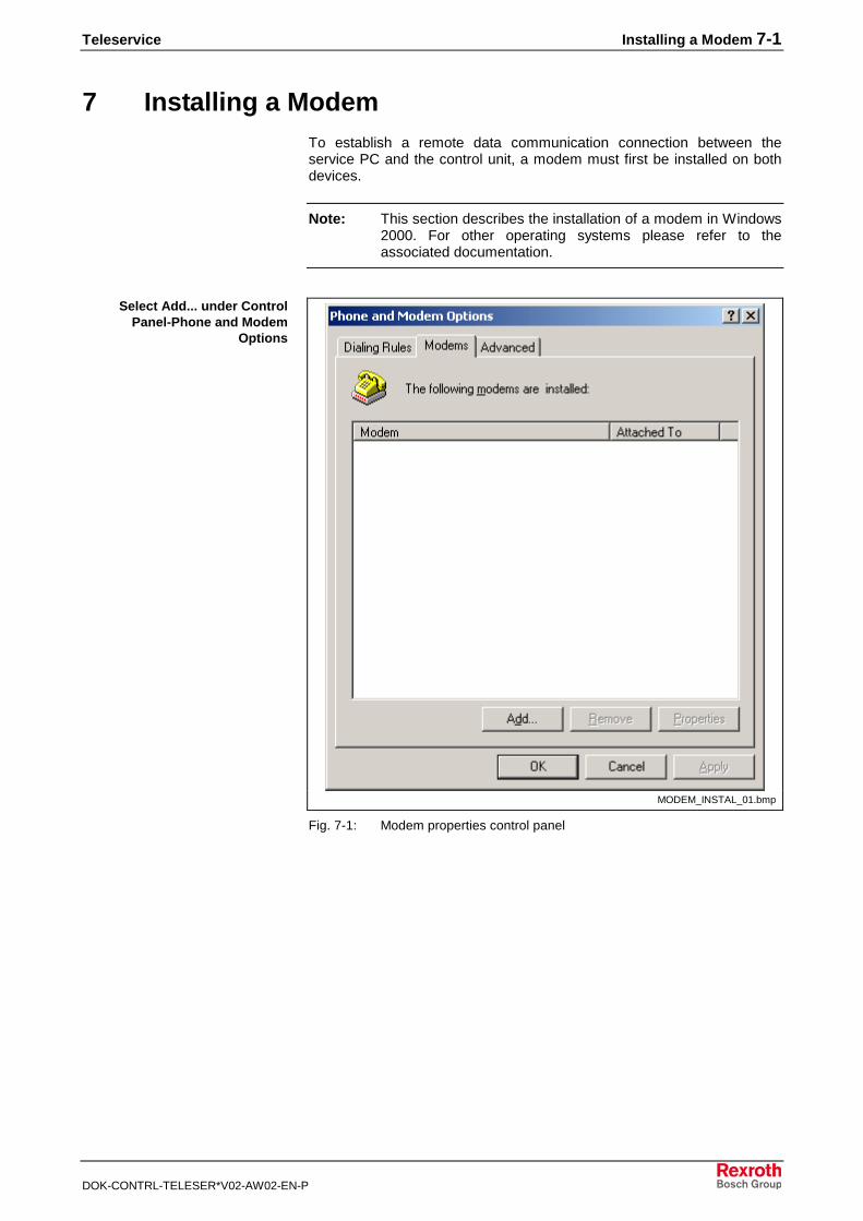
7 Installing a ModemTo establish a remote data communication connection between theservice PC and the control unit, a modem must first be installed on bothdevices.
Note: This section describes the installation of a modem in Windows2000. For other operating systems please refer to theassociated documentation.
MODEM_INSTAL_01.bmp
Fig. 7-1: Modem properties control panel
Select Add... under ControlPanel-Phone and Modem
Options
7-2 Installing a Modem Teleservice
DOK-CONTRL-TELESER*V02-AW02-EN-P
MODEM_INSTAL_02.bmp
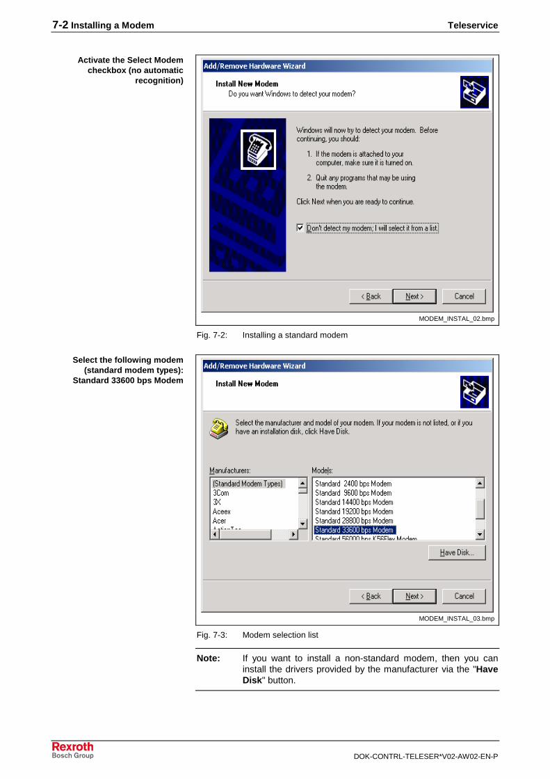
Fig. 7-2: Installing a standard modem
MODEM_INSTAL_03.bmp
Fig. 7-3: Modem selection list
Note: If you want to install a non-standard modem, then you caninstall the drivers provided by the manufacturer via the "HaveDisk" button.
Activate the Select Modemcheckbox (no automatic
recognition)
Select the following modem(standard modem types):
Standard 33600 bps Modem
Teleservice Installing a Modem 7-3
DOK-CONTRL-TELESER*V02-AW02-EN-P
MODEM_INSTAL_04.bmp
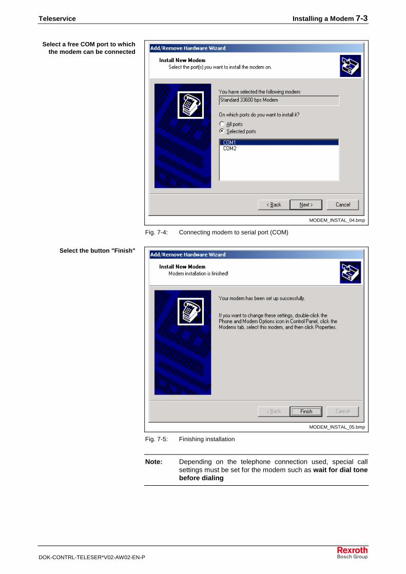
Fig. 7-4: Connecting modem to serial port (COM)
MODEM_INSTAL_05.bmp
Fig. 7-5: Finishing installation
Note: Depending on the telephone connection used, special callsettings must be set for the modem such as wait for dial tonebefore dialing
Select a free COM port to whichthe modem can be connected
Select the button "Finish"
7-4 Installing a Modem Teleservice
DOK-CONTRL-TELESER*V02-AW02-EN-P
Teleservice Installing a Remote Communications Network (RAS) 8-1
DOK-CONTRL-TELESER*V02-AW02-EN-P
8 Installing a Remote Communications Network(RAS)
8.1 General Notes
With RAS (Remote Access Service) Windows provides the possibility ofconnecting RAS client computers via a modem, ISDN or X.25 connectionto a RAS server. Not only is a great variety of clients supported in thisprocess, but it also provides great flexibility in selecting and combining theused network protocols.
The computers connected via RAS with the network can only access theRAS server or the entire network, depending on how the RAS server isconfigured, as if they were connected directly with the network locally.
Note: The installation of a remote communication network (RAS)under Windows 2000 is described here. If you have gotanother operating system please use its documentation.
When a remote session is established, the service PC establishes a RASconnection to the control unit. To do this, the RAS service must beinstalled on the service PC and on the client PC. The service PC is to beconfigured as a RAS client and the client PC as a RAS server. Theinstallation steps required are described in the following.

8-2 Installing a Remote Communications Network (RAS) Teleservice
DOK-CONTRL-TELESER*V02-AW02-EN-P
8.2 Activate RAS on the Control PC
RAS_INSTAL_00.bmp
Fig. 8-1: Properties of RAS
Set the startup type on manual and adopt the setting. Now start theservice via the button "Start".
Configuration of RAS on the Control PC
Note: In order to allow a remote user an RAS access, the user musthave a valid user account on the RAS server. RAS accessrights must be assigned to this account.
For that purpose it is practical to define a special user accountfor the I-Remote connection on the RAS server first. Sincesystem settings may have to be changed by the servicepersonnel during the remote session, it is recommended toinclude this account in the local group of administrators.
Then the account can obtain a remote access right via theRAS management and the callback safety can be configured.
Select in the menu ControlPanel-Administrative Tools-
Services the service "RemoteAccess Manager" and select
"Properties" in the context menuof the service
Teleservice Installing a Remote Communications Network (RAS) 8-3
DOK-CONTRL-TELESER*V02-AW02-EN-P
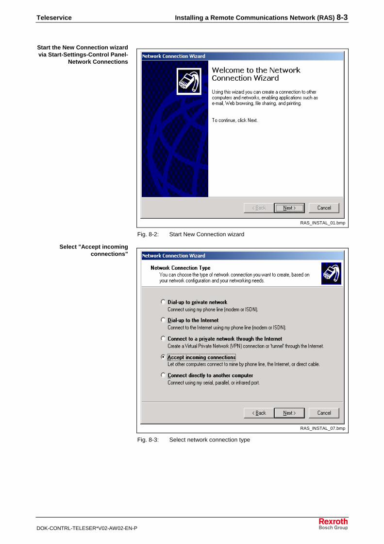
RAS_INSTAL_01.bmp
Fig. 8-2: Start New Connection wizard
RAS_INSTAL_07.bmp
Fig. 8-3: Select network connection type
Start the New Connection wizardvia Start-Settings-Control Panel-
Network Connections
Select "Accept incomingconnections”
8-4 Installing a Remote Communications Network (RAS) Teleservice
DOK-CONTRL-TELESER*V02-AW02-EN-P
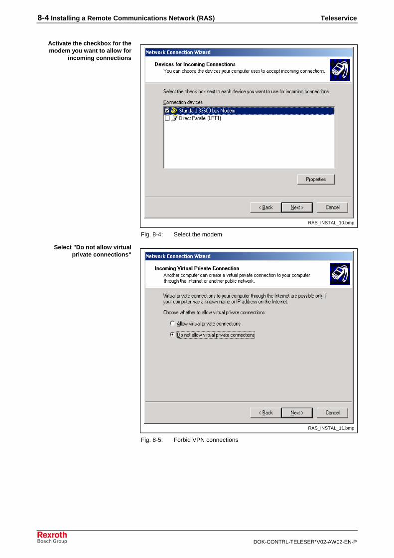
RAS_INSTAL_10.bmp
Fig. 8-4: Select the modem
RAS_INSTAL_11.bmp
Fig. 8-5: Forbid VPN connections
Activate the checkbox for themodem you want to allow for
incoming connections
Select "Do not allow virtualprivate connections"
Teleservice Installing a Remote Communications Network (RAS) 8-5
DOK-CONTRL-TELESER*V02-AW02-EN-P
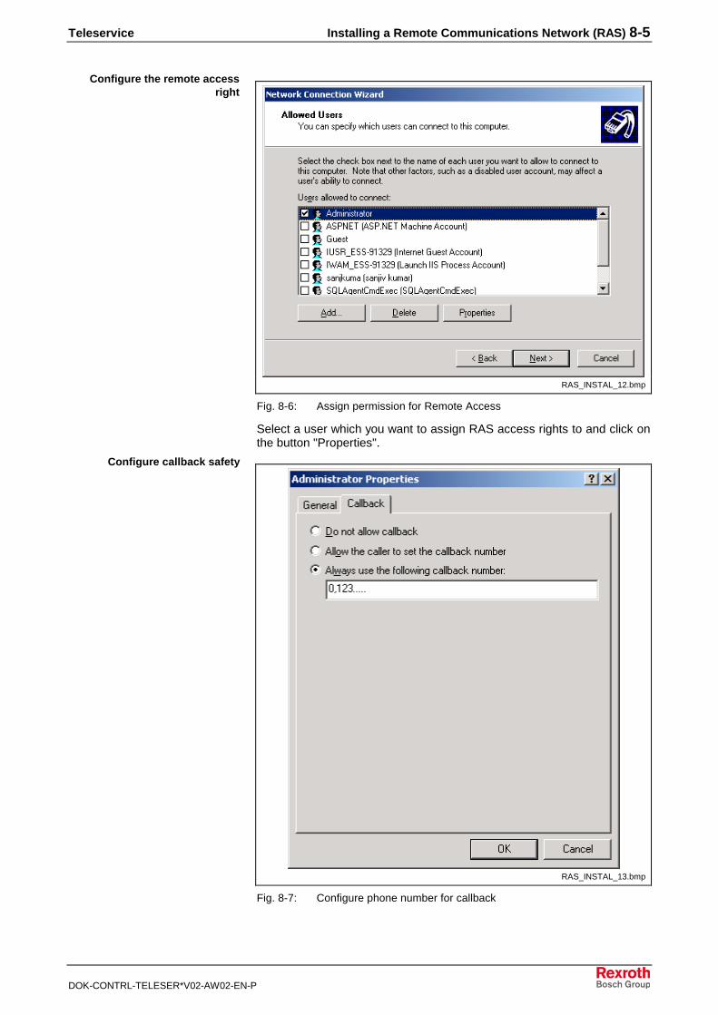
RAS_INSTAL_12.bmp
Fig. 8-6: Assign permission for Remote Access
Select a user which you want to assign RAS access rights to and click onthe button "Properties".
RAS_INSTAL_13.bmp
Fig. 8-7: Configure phone number for callback
Configure the remote accessright
Configure callback safety
8-6 Installing a Remote Communications Network (RAS) Teleservice
DOK-CONTRL-TELESER*V02-AW02-EN-P
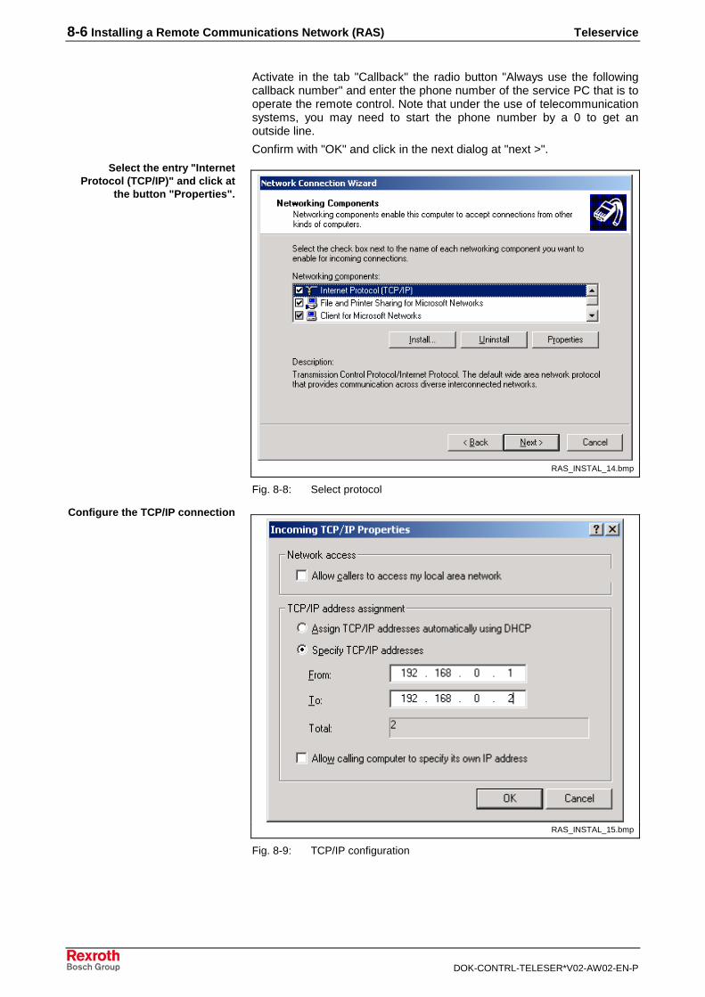
Activate in the tab "Callback" the radio button "Always use the followingcallback number" and enter the phone number of the service PC that is tooperate the remote control. Note that under the use of telecommunicationsystems, you may need to start the phone number by a 0 to get anoutside line.
Confirm with "OK" and click in the next dialog at "next >".
RAS_INSTAL_14.bmp
Fig. 8-8: Select protocol
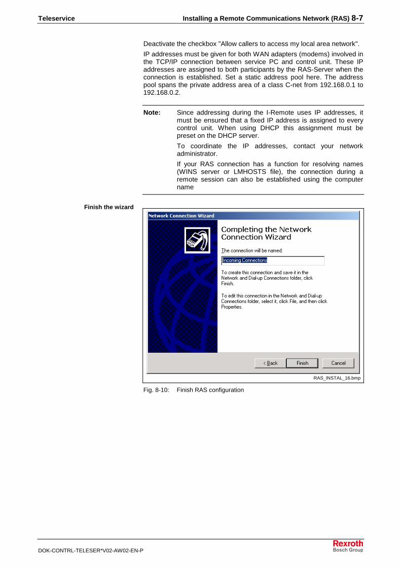
RAS_INSTAL_15.bmp
Fig. 8-9: TCP/IP configuration
Select the entry "InternetProtocol (TCP/IP)" and click at
the button "Properties".
Configure the TCP/IP connection
Teleservice Installing a Remote Communications Network (RAS) 8-7
DOK-CONTRL-TELESER*V02-AW02-EN-P
Deactivate the checkbox "Allow callers to access my local area network".
IP addresses must be given for both WAN adapters (modems) involved inthe TCP/IP connection between service PC and control unit. These IPaddresses are assigned to both participants by the RAS-Server when theconnection is established. Set a static address pool here. The addresspool spans the private address area of a class C-net from 192.168.0.1 to192.168.0.2.
Note: Since addressing during the I-Remote uses IP addresses, itmust be ensured that a fixed IP address is assigned to everycontrol unit. When using DHCP this assignment must bepreset on the DHCP server.
To coordinate the IP addresses, contact your networkadministrator.
If your RAS connection has a function for resolving names(WINS server or LMHOSTS file), the connection during aremote session can also be established using the computername
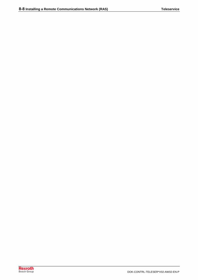
RAS_INSTAL_16.bmp
Fig. 8-10: Finish RAS configuration
Finish the wizard
8-8 Installing a Remote Communications Network (RAS) Teleservice
DOK-CONTRL-TELESER*V02-AW02-EN-P
Teleservice Appendix A: Troubleshooting 9-1
DOK-CONTRL-TELESER*V02-AW02-EN-P
9 Appendix A: Troubleshooting
If NetSupport Manager is operated together with a DOS-based RexrothGUI earlier than V20, there are driver problems after installing theNetSupport Manager software.
These problems are caused by a driver for the NetSupport Manager DOSsupport that is to be loaded in the upper memory area. However, sincethis memory area is already mostly required by the GUI, conflicts canarise.
To resolve these conflicts, replace the following entry in theD:\WINNT\SYSTEM32\AUTOEXEC.NT file:
lh D:\REMCON\ntfsdb /e >nul
with the following line:
D:\REMCON\ntfsdb /e >nul
Note: Then reboot the system!
• Check your modem installation.
• If you are using a telecommunications system, the modem settingsmay have to be adjusted under Control Panel/Modems/Settings.
• Check whether the dial procedure used is correctly set to MFV (multi-frequency) or IWV (pulse dial procedure). Menu item ControlPanel/Modems/Dial Parameters.
• When using a telecommunications system that requires a 0 to obtainan outside line, the remote data communication telephone book entrymust be in the following form: 0,<area code/telephone number>
• Make sure that a current Service Pack (recommended: SP5.0) ofWindows NT4.0 is installed or in case of Windows 2000 make surethat SP4.0 is installed.
• Check your modem installation.
• If you are using a telecommunications system, the modem settingsmay have to be adjusted under Control Panel/Modems/Settings.
• Check whether the dial procedure used is correctly set to MFV (multi-frequency) or IWV (pulse dial procedure). Menu item ControlPanel/Modems/Dial Parameters.
• When using a telecommunications system that requires a 0 to obtainan outside line, the callback configured in the RAS administration mustbe in the following form: 0,<area code/telephone number>.
Make sure that the IP address of the control unit has been correctlyentered. If the target control unit obtains its IP address from a DHCPserver, this may change after the IP lease has expired on the DHCPserver. In this case, a connection can no longer be made via the old IPaddress of the control unit.
To avoid this when using DHCP, please configure the DHCP server insuch a way that the control system is assigned a fixed IP address. Pleasecontact your network administrator.
GUI reports memory error
Dial-up via modem is faulty
RAS connection is unstable
Callback from RAS serverdoesn't work
From the service PC, noconnection to the control unit
can be made via NetSupportcontrol or IE (the RAS
connection is established)
9-2 Appendix A: Troubleshooting Teleservice
DOK-CONTRL-TELESER*V02-AW02-EN-P
Teleservice Appendix B: Limitations in DOS Mode 10-1
DOK-CONTRL-TELESER*V02-AW02-EN-P
10 Appendix B: Limitations in DOS Mode
General InformationDuring a remotely controlled session, various data is transmitted. Inaddition to pure Windows applications, parts of the GUI are in text modeand other parts are in DOS graphics mode, depending on the softwareused. Particularly when transmitting DOS graphics screens, as oftenapplies when working with the graphic user interface (GUI), remotely-controlled operation is only possible with limitations.
DOS Full-Screen Mode
If a DOS full-screen of the control unit is to be displayed during aremotely-controlled session, the service PC only shows a black screen inthe monitoring window. In this case, switch over the DOS mode of thecontrol unit to DOS window mode by pressing ALT+RETURN. The displayon the service PC is then correct.
DOS Graphics WindowIf the BOF or the GUI starts during a running Teleservice session, thescreen colors are not correctly represented on the service PC. However,functionality is not effected.
If a switch-over is made between Windows NT and a DOS graphicswindow during a remotely-controlled session, it may happen that theservice PC in the NetSupport control or in the Internet Explorer shows ablack screen. Depending on the application used on the service PC,please proceed as follows to eliminate this problem.
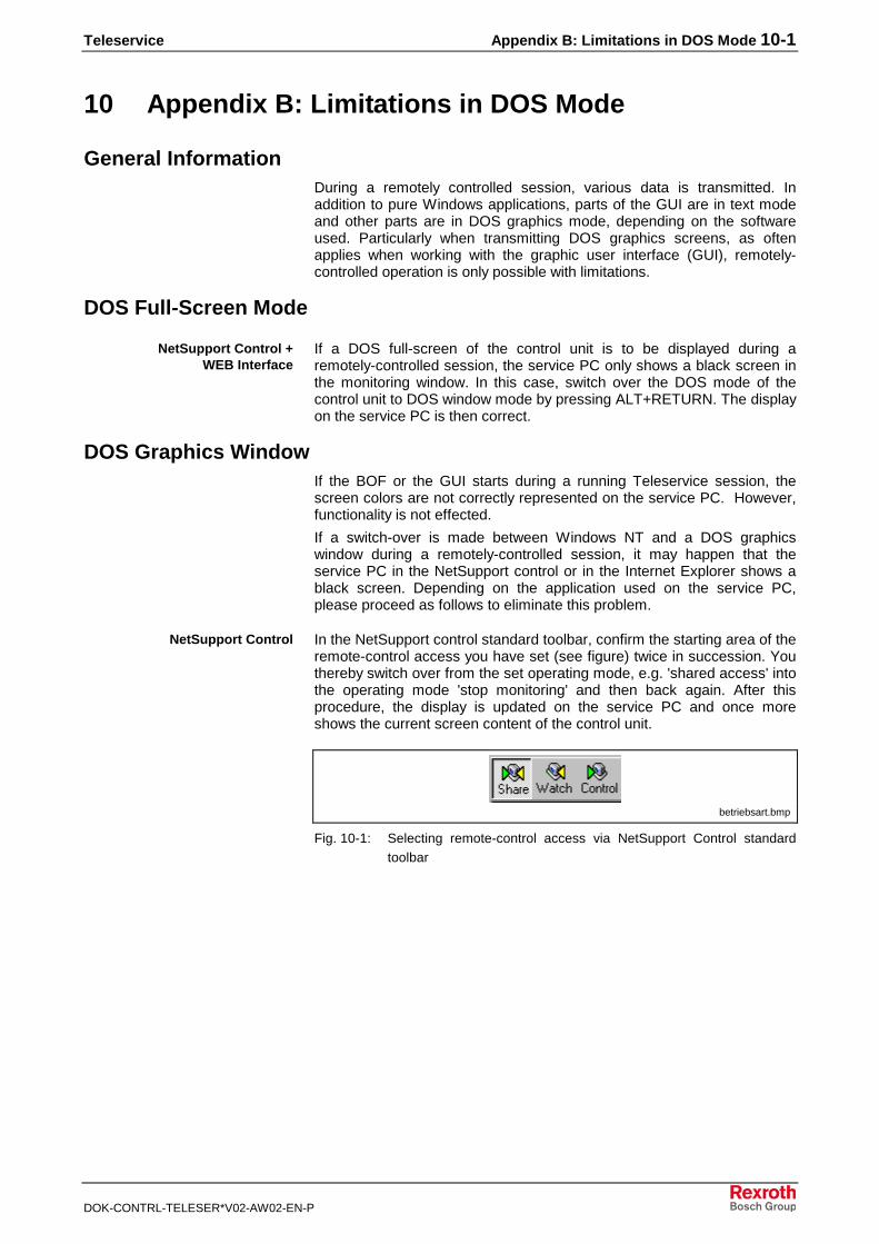
In the NetSupport control standard toolbar, confirm the starting area of theremote-control access you have set (see figure) twice in succession. Youthereby switch over from the set operating mode, e.g. 'shared access' intothe operating mode 'stop monitoring' and then back again. After thisprocedure, the display is updated on the service PC and once moreshows the current screen content of the control unit.
betriebsart.bmp
Fig. 10-1: Selecting remote-control access via NetSupport Control standardtoolbar
NetSupport Control +WEB Interface
NetSupport Control
10-2 Appendix B: Limitations in DOS Mode Teleservice
DOK-CONTRL-TELESER*V02-AW02-EN-P
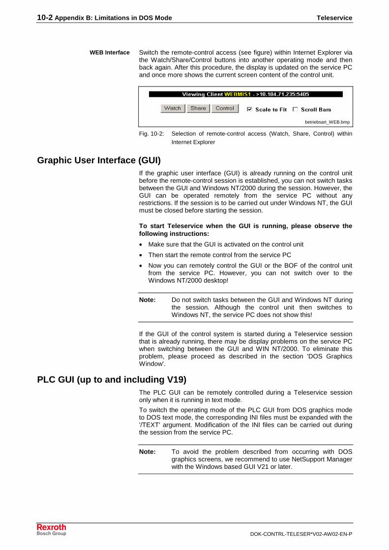
Switch the remote-control access (see figure) within Internet Explorer viathe Watch/Share/Control buttons into another operating mode and thenback again. After this procedure, the display is updated on the service PCand once more shows the current screen content of the control unit.
betriebsart_WEB.bmp
Fig. 10-2: Selection of remote-control access (Watch, Share, Control) withinInternet Explorer
Graphic User Interface (GUI)If the graphic user interface (GUI) is already running on the control unitbefore the remote-control session is established, you can not switch tasksbetween the GUI and Windows NT/2000 during the session. However, theGUI can be operated remotely from the service PC without anyrestrictions. If the session is to be carried out under Windows NT, the GUImust be closed before starting the session.
To start Teleservice when the GUI is running, please observe thefollowing instructions:
• Make sure that the GUI is activated on the control unit
• Then start the remote control from the service PC
• Now you can remotely control the GUI or the BOF of the control unitfrom the service PC. However, you can not switch over to theWindows NT/2000 desktop!
Note: Do not switch tasks between the GUI and Windows NT duringthe session. Although the control unit then switches toWindows NT, the service PC does not show this!
If the GUI of the control system is started during a Teleservice sessionthat is already running, there may be display problems on the service PCwhen switching between the GUI and WIN NT/2000. To eliminate thisproblem, please proceed as described in the section 'DOS GraphicsWindow'.
PLC GUI (up to and including V19)The PLC GUI can be remotely controlled during a Teleservice sessiononly when it is running in text mode.
To switch the operating mode of the PLC GUI from DOS graphics modeto DOS text mode, the corresponding INI files must be expanded with the'/TEXT' argument. Modification of the INI files can be carried out duringthe session from the service PC.
Note: To avoid the problem described from occurring with DOSgraphics screens, we recommend to use NetSupport Managerwith the Windows based GUI V21 or later.
WEB Interface
Teleservice Appendix C: Configuring a Teleservice Session 11-1
DOK-CONTRL-TELESER*V02-AW02-EN-P
11 Appendix C: Configuring a Teleservice Session
General InformationThe Teleservice session between the service PC and the control unit canbe freely configured with regard to important parameters such as
• security (user administration, access rights)
• transport protocol
• available functions on access
• WEB interface, etc.
The configuration can be edited using the 'NetSupport Configurator'application and is stored in the 'CLIENT32.INI' file in the Remcon programdirectory of the control unit.
The 'CLIENT32.INI' file configures the NetSupport client software on thecontrol system.
Overview of Configuration
• Start the 'NetSupport Configurator' application on the control PC.
• Select the 'Advanced' button in the start screen to call up theadvanced client configuration.
• Enter your password in the Security dialog box (the default setting hereis 'service').
• In the Client Configurator, double-click the profile name 'MasterProfile'.
• Carry out the Teleservice configuration using the tabs provided andthen confirm by pressing the 'OK' button.
• Store the configuration under File/Save; after the prompt, do restartthe client.
• Exit the 'NetSupport Configurator'.
The new configuration is then valid on the control system. A description ofthe configuration provided by Bosch Rexroth follows.
Step-by-step configuration
11-2 Appendix C: Configuring a Teleservice Session Teleservice
DOK-CONTRL-TELESER*V02-AW02-EN-P
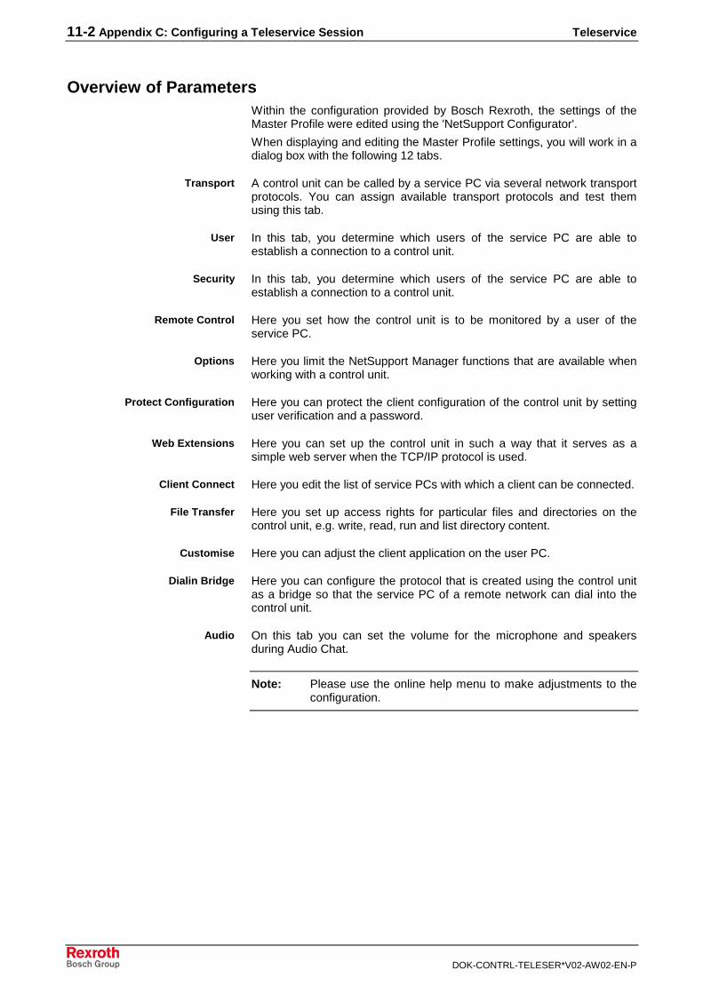
Overview of ParametersWithin the configuration provided by Bosch Rexroth, the settings of theMaster Profile were edited using the 'NetSupport Configurator'.
When displaying and editing the Master Profile settings, you will work in adialog box with the following 12 tabs.
A control unit can be called by a service PC via several network transportprotocols. You can assign available transport protocols and test themusing this tab.
In this tab, you determine which users of the service PC are able toestablish a connection to a control unit.
In this tab, you determine which users of the service PC are able toestablish a connection to a control unit.
Here you set how the control unit is to be monitored by a user of theservice PC.
Here you limit the NetSupport Manager functions that are available whenworking with a control unit.
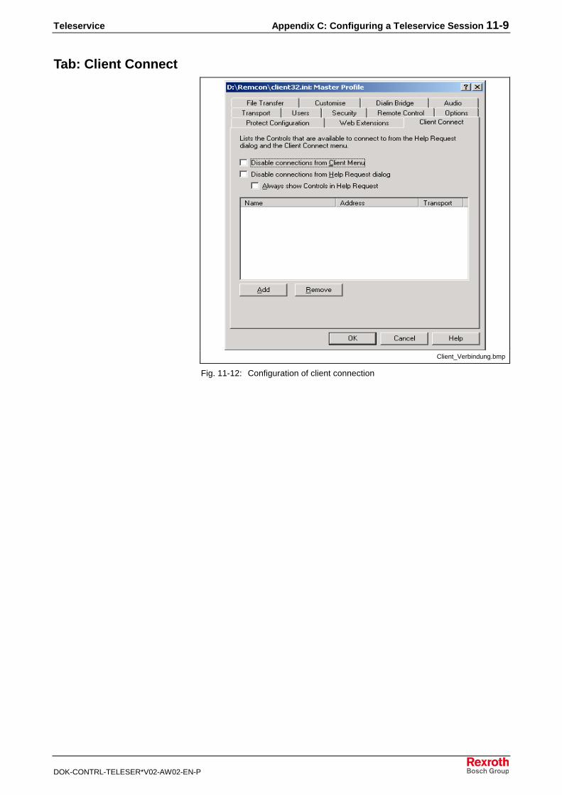
Here you can protect the client configuration of the control unit by settinguser verification and a password.
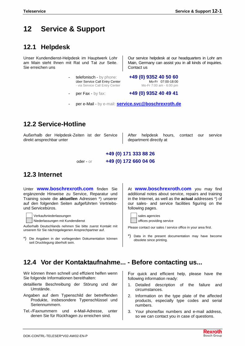
Here you can set up the control unit in such a way that it serves as asimple web server when the TCP/IP protocol is used.
Here you edit the list of service PCs with which a client can be connected.
Here you set up access rights for particular files and directories on thecontrol unit, e.g. write, read, run and list directory content.
Here you can adjust the client application on the user PC.
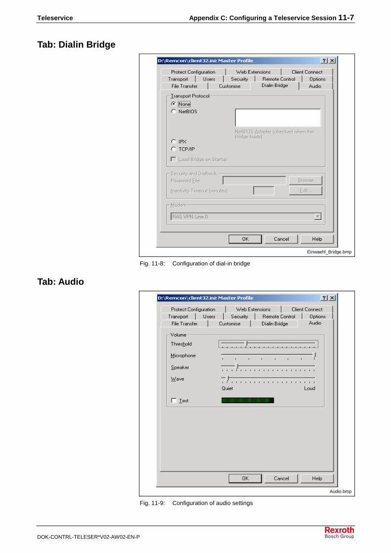
Here you can configure the protocol that is created using the control unitas a bridge so that the service PC of a remote network can dial into thecontrol unit.
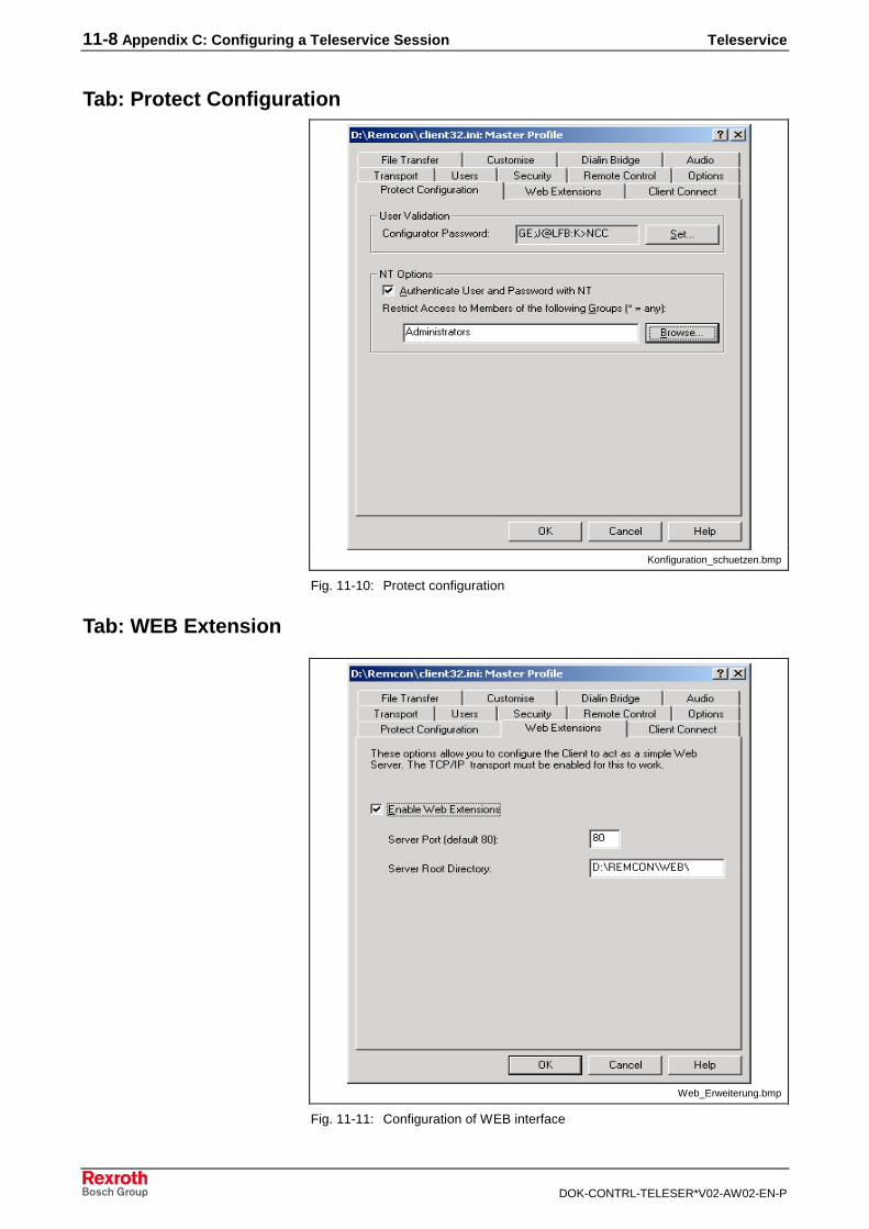
On this tab you can set the volume for the microphone and speakersduring Audio Chat.
Note: Please use the online help menu to make adjustments to theconfiguration.
Transport
User
Security
Remote Control
Options
Protect Configuration
Web Extensions
Client Connect
File Transfer
Customise
Dialin Bridge
Audio
Teleservice Appendix C: Configuring a Teleservice Session 11-3
DOK-CONTRL-TELESER*V02-AW02-EN-P
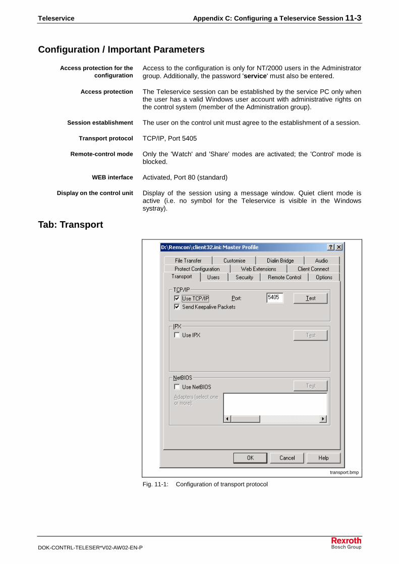
Configuration / Important Parameters
Access to the configuration is only for NT/2000 users in the Administratorgroup. Additionally, the password 'service' must also be entered.
The Teleservice session can be established by the service PC only whenthe user has a valid Windows user account with administrative rights onthe control system (member of the Administration group).
The user on the control unit must agree to the establishment of a session.
TCP/IP, Port 5405
Only the 'Watch' and 'Share' modes are activated; the 'Control' mode isblocked.
Activated, Port 80 (standard)
Display of the session using a message window. Quiet client mode isactive (i.e. no symbol for the Teleservice is visible in the Windowssystray).
Tab: Transport
transport.bmp
Fig. 11-1: Configuration of transport protocol
Access protection for theconfiguration
Access protection
Session establishment
Transport protocol
Remote-control mode
WEB interface
Display on the control unit
11-4 Appendix C: Configuring a Teleservice Session Teleservice
DOK-CONTRL-TELESER*V02-AW02-EN-P
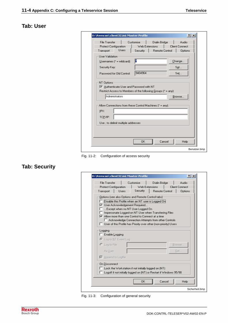
Tab: User
Benutzer.bmp
Fig. 11-2: Configuration of access security
Tab: Security
Sicherheit.bmp
Fig. 11-3: Configuration of general security

Teleservice Appendix C: Configuring a Teleservice Session 11-5
DOK-CONTRL-TELESER*V02-AW02-EN-P
Tab: Remote Control
Fernsteuerung.bmp
Fig. 11-4: Configuration of remote-control options
Tab: Options
Optionen.bmp
Fig. 11-5: Configuration of general options
11-6 Appendix C: Configuring a Teleservice Session Teleservice
DOK-CONTRL-TELESER*V02-AW02-EN-P
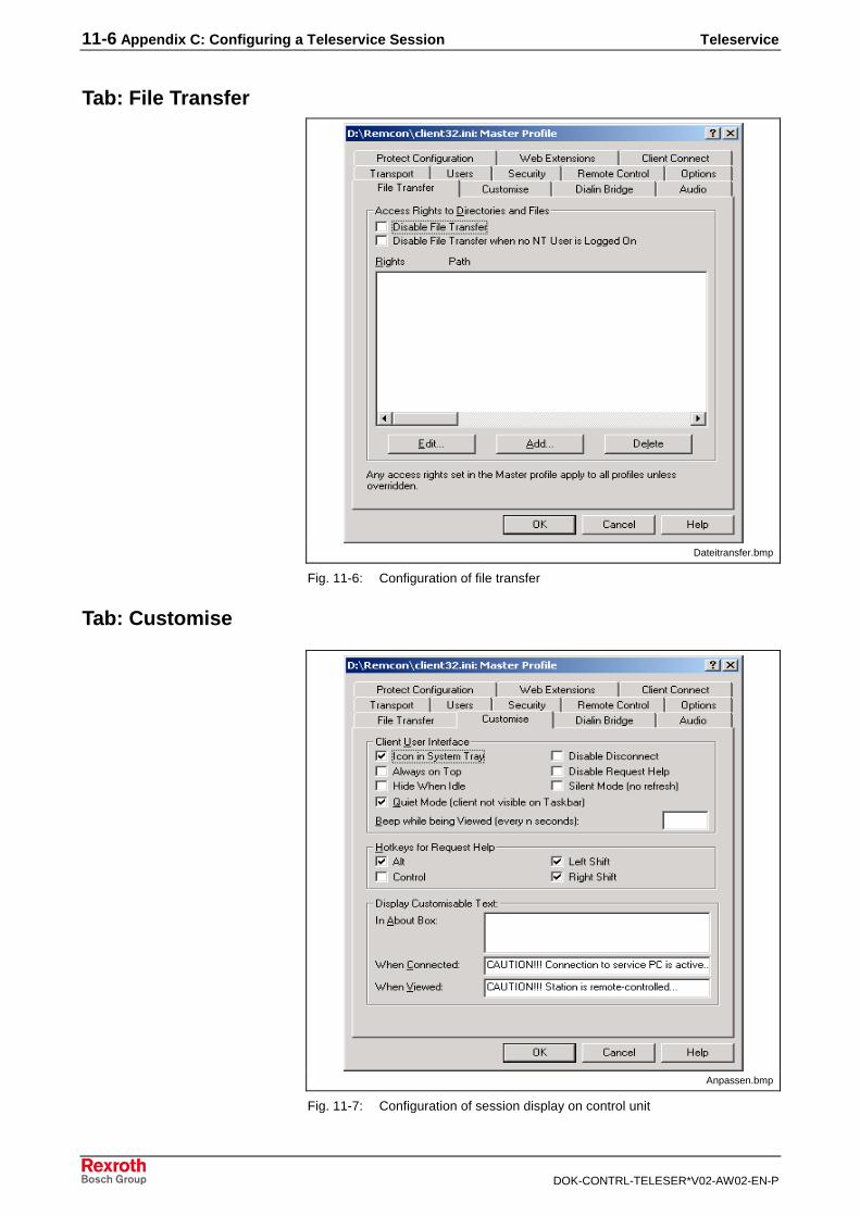
Tab: File Transfer
Dateitransfer.bmp
Fig. 11-6: Configuration of file transfer
Tab: Customise
Anpassen.bmp
Fig. 11-7: Configuration of session display on control unit
Teleservice Appendix C: Configuring a Teleservice Session 11-7
DOK-CONTRL-TELESER*V02-AW02-EN-P
Tab: Dialin Bridge
Einwaehl_Bridge.bmp
Fig. 11-8: Configuration of dial-in bridge
Tab: Audio
Audio.bmp
Fig. 11-9: Configuration of audio settings
11-8 Appendix C: Configuring a Teleservice Session Teleservice
DOK-CONTRL-TELESER*V02-AW02-EN-P
Tab: Protect Configuration
Konfiguration_schuetzen.bmp
Fig. 11-10: Protect configuration
Tab: WEB Extension
Web_Erweiterung.bmp
Fig. 11-11: Configuration of WEB interface
Teleservice Appendix C: Configuring a Teleservice Session 11-9
DOK-CONTRL-TELESER*V02-AW02-EN-P
Tab: Client Connect
Client_Verbindung.bmp
Fig. 11-12: Configuration of client connection

11-10 Appendix C: Configuring a Teleservice Session Teleservice
DOK-CONTRL-TELESER*V02-AW02-EN-P
Teleservice Service & Support 12-1
DOK-CONTRL-TELESER*V02-AW02-EN-P
12 Service & Support
12.1 Helpdesk
Unser Kundendienst-Helpdesk im Hauptwerk Lohram Main steht Ihnen mit Rat und Tat zur Seite.Sie erreichen uns
Our service helpdesk at our headquarters in Lohr amMain, Germany can assist you in all kinds of inquiries.Contact us
- telefonisch - by phone: +49 (0) 9352 40 50 60über Service Call Entry Center Mo-Fr 07:00-18:00- via Service Call Entry Center Mo-Fr 7:00 am - 6:00 pm
- per Fax - by fax: +49 (0) 9352 40 49 41
- per e-Mail - by e-mail: [email protected]
12.2 Service-Hotline
Außerhalb der Helpdesk-Zeiten ist der Servicedirekt ansprechbar unter
After helpdesk hours, contact our servicedepartment directly at
+49 (0) 171 333 88 26
oder - or +49 (0) 172 660 04 06
12.3 Internet
Unter www.boschrexroth.com finden Sieergänzende Hinweise zu Service, Reparatur undTraining sowie die aktuellen Adressen *) unsererauf den folgenden Seiten aufgeführten Vertriebs-und Servicebüros.
Verkaufsniederlassungen
Niederlassungen mit Kundendienst
Außerhalb Deutschlands nehmen Sie bitte zuerst Kontakt mitunserem für Sie nächstgelegenen Ansprechpartner auf.
*) Die Angaben in der vorliegenden Dokumentation könnenseit Drucklegung überholt sein.
At www.boschrexroth.com you may findadditional notes about service, repairs and trainingin the Internet, as well as the actual addresses *) ofour sales- and service facilities figuring on thefollowing pages.
sales agencies
offices providing service
Please contact our sales / service office in your area first.
*) Data in the present documentation may have becomeobsolete since printing.
12.4 Vor der Kontaktaufnahme... - Before contacting us...
Wir können Ihnen schnell und effizient helfen wennSie folgende Informationen bereithalten:
detaillierte Beschreibung der Störung und derUmstände.
Angaben auf dem Typenschild der betreffendenProdukte, insbesondere Typenschlüssel undSeriennummern.
Tel.-/Faxnummern und e-Mail-Adresse, unterdenen Sie für Rückfragen zu erreichen sind.
For quick and efficient help, please have thefollowing information ready:
1. Detailed description of the failure andcircumstances.
2. Information on the type plate of the affectedproducts, especially type codes and serialnumbers.
3. Your phone/fax numbers and e-mail address,so we can contact you in case of questions.

12-2 Service & Support Teleservice
DOK-CONTRL-TELESER*V02-AW02-EN-P
12.5 Kundenbetreuungsstellen - Sales & Service Facilities
Deutschland - Germany vom Ausland: (0) nach Landeskennziffer weglassen!from abroad: don’t dial (0) after country code!
Vertriebsgebiet Mitte Germany Centre
Rexroth Indramat GmbHBgm.-Dr.-Nebel-Str. 2 / Postf. 135797816 Lohr am Main / 97803 Lohr
Kompetenz-Zentrum Europa
Tel.: +49 (0)9352 40-0Fax: +49 (0)9352 40-4885
S E R V I C E A U T O M A T I O N
C A L L E N T R Y C E N T E RH e l p d e s kMO – FR
von 07:00 - 18:00 Uhrfrom 7 am – 6 pm
Tel. +49 (0) 9352 40 50 60Fax +49 (0) 9352 40 49 41
S E R V I C E A U T O M A T I O N
H OTLIN E 24 / 7 / 365
außerhalb der Helpdesk-Zeitout of helpdesk hours
Tel.: +49 (0)172 660 04 06o d e r / o r
Tel.: +49 (0)171 333 88 26
S E R V I C E A U T O M A T I O N
ERSATZTEILE / SPARESverlängerte Ansprechzeit- extended office time -
♦ nur an Werktagen- only on working days -
♦ von 07:00 - 18:00 Uhr- from 7 am - 6 pm -
Tel. +49 (0) 9352 40 42 22
Vertriebsgebiet Süd Germany South
Bosch Rexroth AGLandshuter Allee 8-1080637 München
Tel.: +49 (0)89 127 14-0Fax: +49 (0)89 127 14-490
Vertriebsgebiet West Germany West
Bosch Rexroth AGRegionalzentrum WestBorsigstrasse 1540880 Ratingen
Tel.: +49 (0)2102 409-0Fax: +49 (0)2102 409-406
+49 (0)2102 409-430
Gebiet Südwest Germany South-West
Bosch Rexroth AGService-Regionalzentrum Süd-WestSiemensstr. 170736 Fellbach
Tel.: +49 (0)711 51046–0Fax: +49 (0)711 51046–248
Vertriebsgebiet Nord Germany North
Bosch Rexroth AGWalsroder Str. 9330853 Langenhagen
Tel.: +49 (0) 511 72 66 57-0Service: +49 (0) 511 72 66 57-256Fax: +49 (0) 511 72 66 57-93Service: +49 (0) 511 72 66 57-783
Vertriebsgebiet Mitte Germany Centre
Bosch Rexroth AGRegionalzentrum MitteWaldecker Straße 1364546 Mörfelden-Walldorf
Tel.: +49 (0) 61 05 702-3Fax: +49 (0) 61 05 702-444
Vertriebsgebiet Ost Germany East
Bosch Rexroth AGBeckerstraße 3109120 Chemnitz
Tel.: +49 (0)371 35 55-0Fax: +49 (0)371 35 55-333
Vertriebsgebiet Ost Germany East
Bosch Rexroth AGRegionalzentrum OstWalter-Köhn-Str. 4d04356 Leipzig
Tel.: +49 (0)341 25 61-0Fax: +49 (0)341 25 61-111
Teleservice Service & Support 12-3
DOK-CONTRL-TELESER*V02-AW02-EN-P
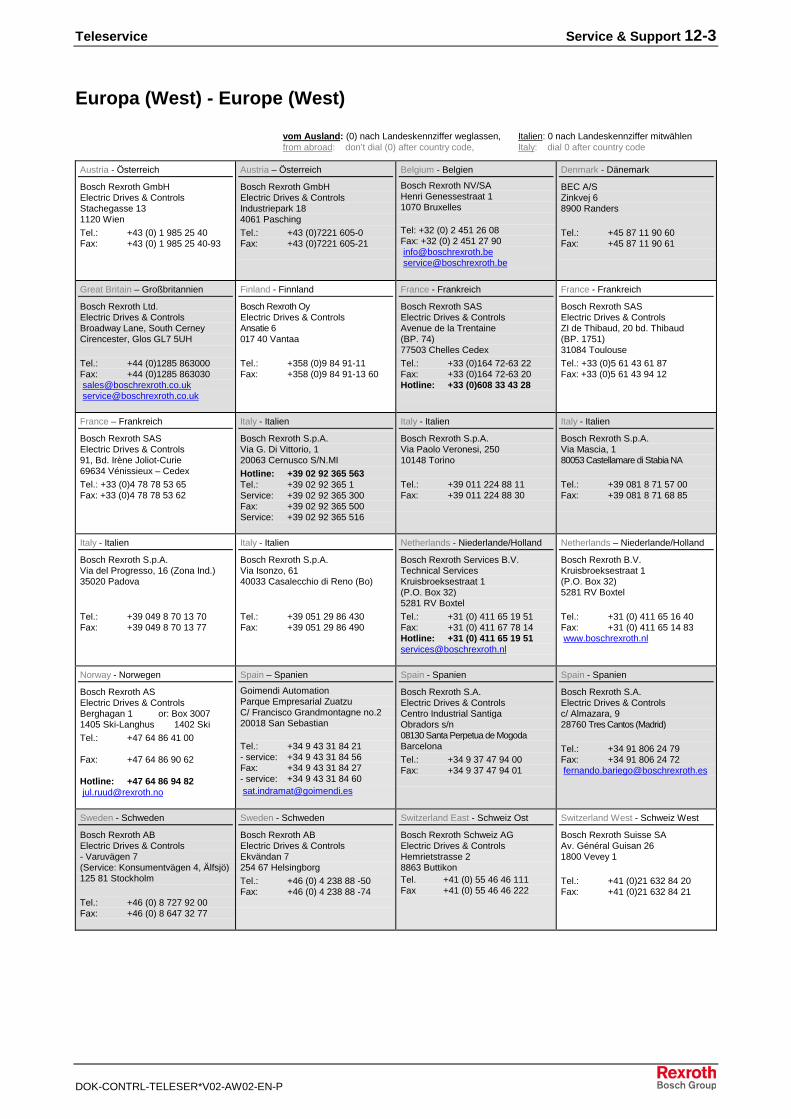
Europa (West) - Europe (West)
vom Ausland: (0) nach Landeskennziffer weglassen, Italien: 0 nach Landeskennziffer mitwählenfrom abroad: don’t dial (0) after country code, Italy: dial 0 after country code
Austria - Österreich
Bosch Rexroth GmbHElectric Drives & ControlsStachegasse 131120 Wien
Tel.: +43 (0) 1 985 25 40Fax: +43 (0) 1 985 25 40-93
Austria – Österreich
Bosch Rexroth GmbHElectric Drives & ControlsIndustriepark 184061 Pasching
Tel.: +43 (0)7221 605-0Fax: +43 (0)7221 605-21
Belgium - Belgien
Bosch Rexroth NV/SAHenri Genessestraat 11070 Bruxelles
Tel: +32 (0) 2 451 26 08Fax: +32 (0) 2 451 27 90 [email protected] [email protected]
Denmark - Dänemark
BEC A/SZinkvej 68900 Randers
Tel.: +45 87 11 90 60Fax: +45 87 11 90 61
Great Britain – Großbritannien
Bosch Rexroth Ltd.Electric Drives & ControlsBroadway Lane, South CerneyCirencester, Glos GL7 5UH
Tel.: +44 (0)1285 863000Fax: +44 (0)1285 863030 [email protected] [email protected]
Finland - Finnland
Bosch Rexroth OyElectric Drives & ControlsAnsatie 6017 40 Vantaa
Tel.: +358 (0)9 84 91-11Fax: +358 (0)9 84 91-13 60
France - Frankreich
Bosch Rexroth SASElectric Drives & ControlsAvenue de la Trentaine(BP. 74)77503 Chelles Cedex
Tel.: +33 (0)164 72-63 22Fax: +33 (0)164 72-63 20Hotline: +33 (0)608 33 43 28
France - Frankreich
Bosch Rexroth SASElectric Drives & ControlsZI de Thibaud, 20 bd. Thibaud(BP. 1751)31084 Toulouse
Tel.: +33 (0)5 61 43 61 87Fax: +33 (0)5 61 43 94 12
France – Frankreich
Bosch Rexroth SASElectric Drives & Controls91, Bd. Irène Joliot-Curie69634 Vénissieux – Cedex
Tel.: +33 (0)4 78 78 53 65Fax: +33 (0)4 78 78 53 62
Italy - Italien
Bosch Rexroth S.p.A.Via G. Di Vittorio, 120063 Cernusco S/N.MI
Hotline: +39 02 92 365 563Tel.: +39 02 92 365 1Service: +39 02 92 365 300Fax: +39 02 92 365 500Service: +39 02 92 365 516
Italy - Italien
Bosch Rexroth S.p.A.Via Paolo Veronesi, 25010148 Torino
Tel.: +39 011 224 88 11Fax: +39 011 224 88 30
Italy - Italien
Bosch Rexroth S.p.A.Via Mascia, 180053 Castellamare di Stabia NA
Tel.: +39 081 8 71 57 00Fax: +39 081 8 71 68 85
Italy - Italien
Bosch Rexroth S.p.A.Via del Progresso, 16 (Zona Ind.)35020 Padova
Tel.: +39 049 8 70 13 70Fax: +39 049 8 70 13 77
Italy - Italien
Bosch Rexroth S.p.A.Via Isonzo, 6140033 Casalecchio di Reno (Bo)
Tel.: +39 051 29 86 430Fax: +39 051 29 86 490
Netherlands - Niederlande/Holland
Bosch Rexroth Services B.V.Technical ServicesKruisbroeksestraat 1(P.O. Box 32)5281 RV Boxtel
Tel.: +31 (0) 411 65 19 51Fax: +31 (0) 411 67 78 14Hotline: +31 (0) 411 65 19 [email protected]
Netherlands – Niederlande/Holland
Bosch Rexroth B.V.Kruisbroeksestraat 1(P.O. Box 32)5281 RV Boxtel
Tel.: +31 (0) 411 65 16 40Fax: +31 (0) 411 65 14 83 www.boschrexroth.nl
Norway - Norwegen
Bosch Rexroth ASElectric Drives & ControlsBerghagan 1 or: Box 30071405 Ski-Langhus 1402 Ski
Tel.: +47 64 86 41 00
Fax: +47 64 86 90 62
Hotline: +47 64 86 94 82 [email protected]
Spain – Spanien
Goimendi AutomationParque Empresarial ZuatzuC/ Francisco Grandmontagne no.220018 San Sebastian
Tel.: +34 9 43 31 84 21- service: +34 9 43 31 84 56Fax: +34 9 43 31 84 27- service: +34 9 43 31 84 60 [email protected]
Spain - Spanien
Bosch Rexroth S.A.Electric Drives & ControlsCentro Industrial SantigaObradors s/n08130 Santa Perpetua de MogodaBarcelona
Tel.: +34 9 37 47 94 00Fax: +34 9 37 47 94 01
Spain - Spanien
Bosch Rexroth S.A.Electric Drives & Controlsc/ Almazara, 928760 Tres Cantos (Madrid)
Tel.: +34 91 806 24 79Fax: +34 91 806 24 72 [email protected]
Sweden - Schweden
Bosch Rexroth ABElectric Drives & Controls- Varuvägen 7(Service: Konsumentvägen 4, Älfsjö)125 81 Stockholm
Tel.: +46 (0) 8 727 92 00Fax: +46 (0) 8 647 32 77
Sweden - Schweden
Bosch Rexroth ABElectric Drives & ControlsEkvändan 7254 67 Helsingborg
Tel.: +46 (0) 4 238 88 -50Fax: +46 (0) 4 238 88 -74
Switzerland East - Schweiz Ost
Bosch Rexroth Schweiz AGElectric Drives & ControlsHemrietstrasse 28863 ButtikonTel. +41 (0) 55 46 46 111Fax +41 (0) 55 46 46 222
Switzerland West - Schweiz West
Bosch Rexroth Suisse SAAv. Général Guisan 261800 Vevey 1
Tel.: +41 (0)21 632 84 20Fax: +41 (0)21 632 84 21
12-4 Service & Support Teleservice
DOK-CONTRL-TELESER*V02-AW02-EN-P
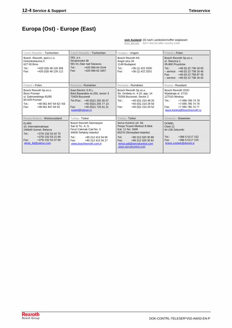
Europa (Ost) - Europe (East)
vom Ausland: (0) nach Landeskennziffer weglassen from abroad: don’t dial (0) after country code
Czech Republic - Tschechien
Bosch -Rexroth, spol.s.r.o.Hviezdoslavova 5627 00 Brno
Tel.: +420 (0)5 48 126 358Fax: +420 (0)5 48 126 112
Czech Republic - Tschechien
DEL a.s.Strojírenská 38591 01 Zdar nad SázavouTel.: +420 566 64 3144Fax: +420 566 62 1657
Hungary - Ungarn
Bosch Rexroth Kft.Angol utca 341149 Budapest
Tel.: +36 (1) 422 3200Fax: +36 (1) 422 3201
Poland – Polen
Bosch Rexroth Sp.zo.o.ul. Staszica 105-800 Pruszków
Tel.: +48 (0) 22 738 18 00– service: +48 (0) 22 738 18 46Fax: +48 (0) 22 758 87 35– service: +48 (0) 22 738 18 42
Poland – Polen
Bosch Rexroth Sp.zo.o.Biuro Poznanul. Dabrowskiego 81/8560-529 Poznan
Tel.: +48 061 847 64 62 /-63Fax: +48 061 847 64 02
Romania - Rumänien
East Electric S.R.L.Bdul Basarabia no.250, sector 373429 Bucuresti
Tel./Fax:: +40 (0)21 255 35 07+40 (0)21 255 77 13
Fax: +40 (0)21 725 61 21 [email protected]
Romania - Rumänien
Bosch Rexroth Sp.zo.o.Str. Drobety nr. 4-10, app. 1470258 Bucuresti, Sector 2
Tel.: +40 (0)1 210 48 25+40 (0)1 210 29 50
Fax: +40 (0)1 210 29 52
Russia - Russland
Bosch Rexroth OOOWjatskaja ul. 27/15127015 Moskau
Tel.: +7-095-785 74 78+7-095 785 74 79
Fax: +7 095 785 74 77 [email protected]
Russia Belarus - Weissrussland
ELMIS10, Internationalnaya246640 Gomel, Belarus
Tel.: +375/ 232 53 42 70+375/ 232 53 21 69
Fax: +375/ 232 53 37 69 [email protected]
Turkey - Türkei
Bosch Rexroth OtomasyonSan & Tic. A..S.Fevzi Cakmak Cad No. 334630 Sefaköy Istanbul
Tel.: +90 212 413 34 00Fax: +90 212 413 34 17 www.boschrexroth.com.tr
Turkey - Türkei
Servo Kontrol Ltd. Sti.Perpa Ticaret Merkezi B BlokKat: 11 No: 160980270 Okmeydani-Istanbul
Tel: +90 212 320 30 80Fax: +90 212 320 30 81 [email protected] www.servokontrol.com
Slowenia - Slowenien
DOMELOtoki 2164 228 Zelezniki
Tel.: +386 5 5117 152Fax: +386 5 5117 225 [email protected]

Teleservice Service & Support 12-5
DOK-CONTRL-TELESER*V02-AW02-EN-P
Africa, Asia, Australia - incl. Pacific Rim
Australia - Australien
AIMS - Australian IndustrialMachinery Services Pty. Ltd.28 Westside DriveLaverton North Vic 3026Melbourne
Tel.: +61 3 93 14 3321Fax: +61 3 93 14 3329Hotlines: +61 3 93 14 3321
+61 4 19 369 195 [email protected]
Australia - Australien
Bosch Rexroth Pty. Ltd.No. 7, Endeavour WayBraeside Victoria, 31 95Melbourne
Tel.: +61 3 95 80 39 33Fax: +61 3 95 80 17 33 [email protected]
China
Shanghai Bosch RexrothHydraulics & Automation Ltd.Waigaoqiao, Free Trade ZoneNo.122, Fu Te Dong Yi RoadShanghai 200131 - P.R.China
Tel.: +86 21 58 66 30 30Fax: +86 21 58 66 55 [email protected][email protected]
China
Shanghai Bosch RexrothHydraulics & Automation Ltd.4/f, Marine TowerNo.1, Pudong AvenueShanghai 200120 - P.R.China
Tel: +86 21 68 86 15 88Fax: +86 21 58 40 65 77
China
Bosch Rexroth China Ltd.15/F China World Trade Center1, Jianguomenwai AvenueBeijing 100004, P.R.China
Tel.: +86 10 65 05 03 80Fax: +86 10 65 05 03 79
China
Bosch Rexroth China Ltd.Guangzhou Repres. OfficeRoom 1014-1016, Metro Plaza,Tian He District, 183 Tian He Bei RdGuangzhou 510075, P.R.China
Tel.: +86 20 8755-0030+86 20 8755-0011
Fax: +86 20 8755-2387
China
Bosch Rexroth (China) Ltd.A-5F., 123 Lian Shan StreetSha He Kou DistrictDalian 116 023, P.R.China
Tel.: +86 411 46 78 930Fax: +86 411 46 78 932
China
Melchers GmbHBRC-SE, Tightening & Press-fit13 Floor Est Ocean CentreNo.588 Yanan Rd. East65 Yanan Rd. WestShanghai 200001
Tel.: +86 21 6352 8848Fax: +86 21 6351 3138
Hongkong
Bosch Rexroth (China) Ltd.6th Floor,Yeung Yiu Chung No.6 Ind Bldg.19 Cheung Shun StreetCheung Sha Wan,Kowloon, Hongkong
Tel.: +852 22 62 51 00Fax: +852 27 41 33 44
India - Indien
Bosch Rexroth (India) Ltd.Electric Drives & ControlsPlot. No.96, Phase IIIPeenya Industrial AreaBangalore – 560058
Tel.: +91 80 51 17 0-211...-218Fax: +91 80 83 94 345
+91 80 83 97 374
India - Indien
Bosch Rexroth (India) Ltd.Electric Drives & ControlsAdvance House, II FloorArk Industrial CompoundNarol Naka, Makwana RoadAndheri (East), Mumbai - 400 059
Tel.: +91 22 28 56 32 90+91 22 28 56 33 18
Fax: +91 22 28 56 32 93
India - Indien
Bosch Rexroth (India) Ltd.S-10, Green Park ExtensionNew Delhi – 110016
Tel.: +91 11 26 56 65 25+91 11 26 56 65 27
Fax: +91 11 26 56 68 87
Indonesia - Indonesien
PT. Bosch RexrothBuilding # 202, CilandakCommercial EstateJl. Cilandak KKO, Jakarta 12560
Tel.: +62 21 7891169 (5 lines)Fax: +62 21 7891170 - [email protected]
Japan
Bosch Rexroth Automation Corp.Service Center JapanYutakagaoka 1810, Meito-ku,NAGOYA 465-0035, Japan
Tel.: +81 52 777 88 41+81 52 777 88 53+81 52 777 88 79
Fax: +81 52 777 89 01
Japan
Bosch Rexroth Automation Corp.Electric Drives & Controls2F, I.R. BuildingNakamachidai 4-26-44, Tsuzuki-kuYOKOHAMA 224-0041, Japan
Tel.: +81 45 942 72 10Fax: +81 45 942 03 41
Korea
Bosch Rexroth-Korea Ltd.Electric Drives and ControlsBongwoo Bldg. 7FL, 31-7, 1GaJangchoong-dong, Jung-guSeoul, 100-391
Tel.: +82 234 061 813Fax: +82 222 641 295
Korea
Bosch Rexroth-Korea Ltd.1515-14 Dadae-Dong, Saha-guElectric Drives & ControlsPusan Metropolitan City, 604-050
Tel.: +82 51 26 00 741Fax: +82 51 26 00 747 [email protected]
Malaysia
Bosch Rexroth Sdn.Bhd.11, Jalan U8/82, Seksyen U840150 Shah AlamSelangor, Malaysia
Tel.: +60 3 78 44 80 00Fax: +60 3 78 45 48 00 [email protected] [email protected]
Singapore - Singapur
Bosch Rexroth Pte Ltd15D Tuas RoadSingapore 638520
Tel.: +65 68 61 87 33Fax: +65 68 61 18 25 sanjay.nemade
@boschrexroth.com.sg
South Africa - Südafrika
TECTRA Automation (Pty) Ltd.71 Watt Street, MeadowdaleEdenvale 1609
Tel.: +27 11 971 94 00Fax: +27 11 971 94 40Hotline: +27 82 903 29 23 [email protected]
Taiwan
Bosch Rexroth Co., Ltd.Taichung Industrial AreaNo.19, 38 RoadTaichung, Taiwan 407, R.O.C.
Tel : +886 - 4 -235 08 383Fax: +886 - 4 -235 08 586 [email protected] [email protected]
Taiwan
Bosch Rexroth Co., Ltd.Tainan BranchNo. 17, Alley 24, Lane 737Chung Cheng N.Rd. YungkangTainan Hsien, Taiwan, R.O.C.
Tel : +886 - 6 –253 6565Fax: +886 - 6 –253 4754 [email protected]
Thailand
NC Advance Technology Co. Ltd.59/76 Moo 9Ramintra road 34Tharang, Bangkhen,Bangkok 10230
Tel.: +66 2 943 70 62 +66 2 943 71 21Fax: +66 2 509 23 62Hotline +66 1 984 61 52 [email protected]
12-6 Service & Support Teleservice
DOK-CONTRL-TELESER*V02-AW02-EN-P
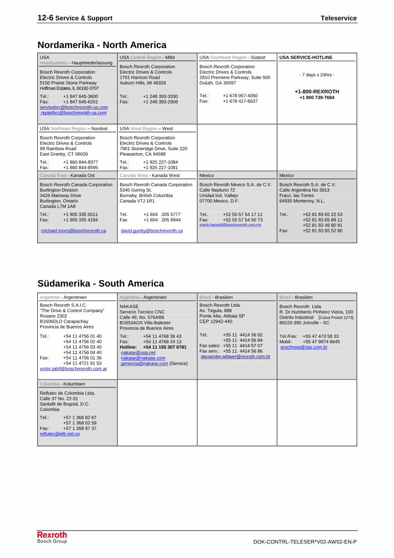
Nordamerika - North AmericaUSAHeadquarters - Hauptniederlassung
Bosch Rexroth CorporationElectric Drives & Controls5150 Prairie Stone ParkwayHoffman Estates, IL 60192-3707
Tel.: +1 847 645-3600Fax: +1 847 [email protected] [email protected]
USA Central Region - Mitte
Bosch Rexroth CorporationElectric Drives & Controls1701 Harmon RoadAuburn Hills, MI 48326
Tel.: +1 248 393-3330Fax: +1 248 393-2906
USA Southeast Region - Südost
Bosch Rexroth CorporationElectric Drives & Controls2810 Premiere Parkway, Suite 500Duluth, GA 30097
Tel.: +1 678 957-4050Fax: +1 678 417-6637
USA SERVICE-HOTLINE
- 7 days x 24hrs -
+1-800-REXROTH+1 800 739-7684
USA Northeast Region – Nordost
Bosch Rexroth CorporationElectric Drives & Controls99 Rainbow RoadEast Granby, CT 06026
Tel.: +1 860 844-8377Fax: +1 860 844-8595
USA West Region – West
Bosch Rexroth CorporationElectric Drives & Controls7901 Stoneridge Drive, Suite 220Pleasanton, CA 94588
Tel.: +1 925 227-1084Fax: +1 925 227-1081
Canada East - Kanada Ost
Bosch Rexroth Canada CorporationBurlington Division3426 Mainway DriveBurlington, OntarioCanada L7M 1A8
Tel.: +1 905 335 5511Fax: +1 905 335 4184
Canada West - Kanada West
Bosch Rexroth Canada Corporation5345 Goring St.Burnaby, British ColumbiaCanada V7J 1R1
Tel. +1 604 205 5777Fax +1 604 205 6944
Mexico
Bosch Rexroth Mexico S.A. de C.V.Calle Neptuno 72Unidad Ind. Vallejo07700 Mexico, D.F.
Tel.: +52 55 57 54 17 11Fax: +52 55 57 54 50 [email protected]
Mexico
Bosch Rexroth S.A. de C.V.Calle Argentina No 3913Fracc. las Torres64930 Monterrey, N.L.
Tel.: +52 81 83 65 22 53+52 81 83 65 89 11+52 81 83 49 80 91
Fax: +52 81 83 65 52 80
Südamerika - South AmericaArgentina - Argentinien
Bosch Rexroth S.A.I.C."The Drive & Control Company"Rosario 2302B1606DLD CarapachayProvincia de Buenos Aires
Tel.: +54 11 4756 01 40+54 11 4756 02 40+54 11 4756 03 40+54 11 4756 04 40
Fax: +54 11 4756 01 36+54 11 4721 91 53
Argentina - Argentinien
NAKASEServicio Tecnico CNCCalle 49, No. 5764/66B1653AOX Villa BalesterProvincia de Buenos Aires
Tel.: +54 11 4768 36 43Fax: +54 11 4768 24 13Hotline: +54 11 155 307 6781 [email protected] [email protected] [email protected] (Service)
Brazil - Brasilien
Bosch Rexroth Ltda.Av. Tégula, 888Ponte Alta, Atibaia SPCEP 12942-440
Tel.: +55 11 4414 56 92+55 11 4414 56 84
Fax sales: +55 11 4414 57 07Fax serv.: +55 11 4414 56 86 [email protected]
Brazil - Brasilien
Bosch Rexroth Ltda.R. Dr.Humberto Pinheiro Vieira, 100Distrito Industrial [Caixa Postal 1273]89220-390 Joinville - SC
Tel./Fax: +55 47 473 58 33Mobil: +55 47 9974 6645 [email protected]
Columbia - Kolumbien
Reflutec de Colombia Ltda.Calle 37 No. 22-31Santafé de Bogotá, D.C.Colombia
Tel.: +57 1 368 82 67+57 1 368 02 59
Fax: +57 1 268 97 [email protected]
Teleservice
DOK-CONTRL-TELESER*V02-AW02-EN-P
Notes

Printed in GermanyDOK-CONTRL-TELESER*V02-AW02-EN-PR911294748
Bosch Rexroth AGElectric Drives and ControlsP.O. Box 13 5797803 Lohr, GermanyBgm.-Dr.-Nebel-Str. 297816 Lohr, GermanyPhone +49 (0)93 52-40-50 60Fax +49 (0)93 52-40-49 [email protected]