rf analysis basics - keysight · w-cdma/hspa/hspa+ wlan lte/lte-a fdd lte/lte-a tdd short range...
TRANSCRIPT
Understanding RF and Microwave Analysis Basics
Kimberly Cassacia
Product Line Brand Manager
Keysight Technologies
PageAgenda
– RF Signal Analyzer Overview & Basic Settings
• Overview of signal analysis – measurements, instrument block diagram
• Initial settings to capture a signal – frequency, span, reference level
• Improving the quality of your measurement – averaging, RBW, sweep time
• How DANL, sensitivity, and phase noise can impact a measurement
– Signal Generators
• Overview of signal generation – signals, instrument block diagram
– Signal Analyzer & Signal Generator Applications
– Wrap-up and Q&A
Understanding RF &
µW Analysis Basics 2
Page
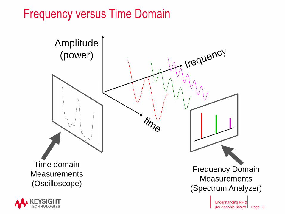
Frequency versus Time Domain
Time domain
Measurements
(Oscilloscope)
Frequency Domain
Measurements
(Spectrum Analyzer)
Amplitude
(power)
Understanding RF &
µW Analysis Basics 3
Page
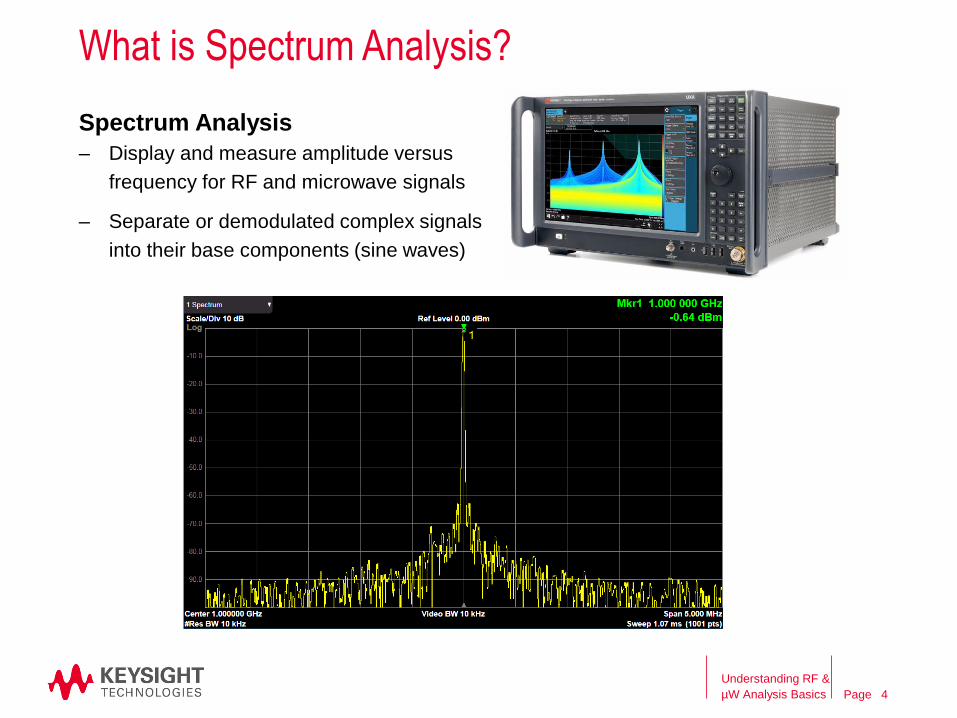
What is Spectrum Analysis?
Spectrum Analysis
– Display and measure amplitude versus
frequency for RF and microwave signals
– Separate or demodulated complex signals
into their base components (sine waves)
Understanding RF &
µW Analysis Basics 4
Page
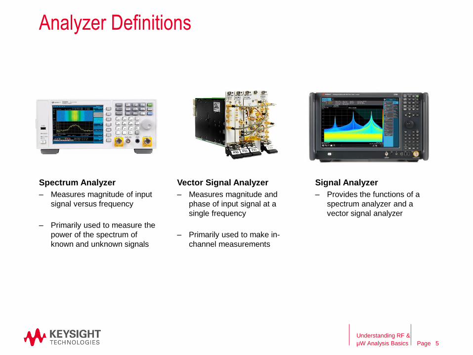
Spectrum Analyzer
Analyzer Definitions
Vector Signal Analyzer Signal Analyzer
– Measures magnitude of input
signal versus frequency
– Primarily used to measure the
power of the spectrum of
known and unknown signals
– Measures magnitude and
phase of input signal at a
single frequency
– Primarily used to make in-
channel measurements
– Provides the functions of a
spectrum analyzer and a
vector signal analyzer
Understanding RF &
µW Analysis Basics 5
Page
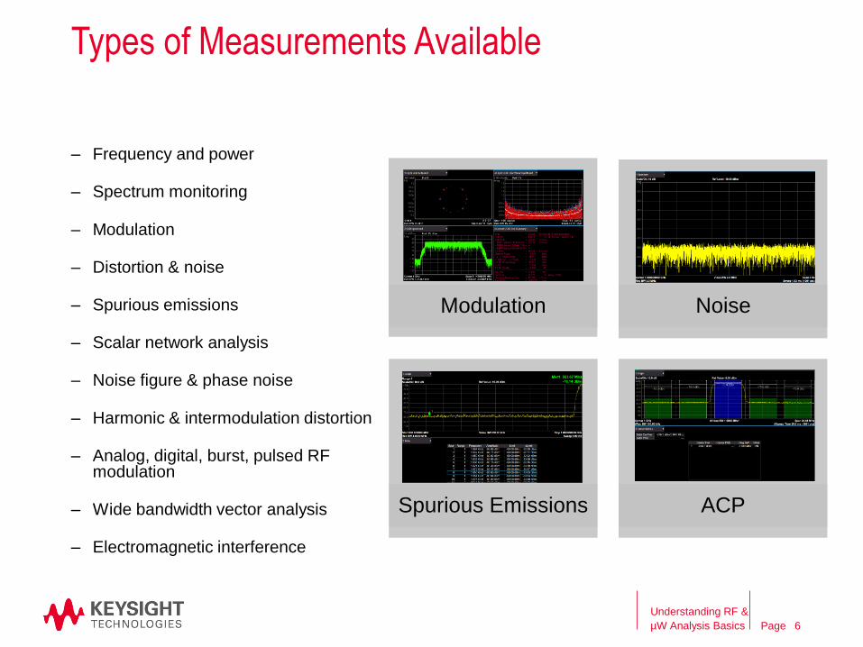
Types of Measurements Available
– Frequency and power
– Spectrum monitoring
– Modulation
– Distortion & noise
– Spurious emissions
– Scalar network analysis
– Noise figure & phase noise
– Harmonic & intermodulation distortion
– Analog, digital, burst, pulsed RF modulation
– Wide bandwidth vector analysis
– Electromagnetic interference
Modulation Noise
Spurious Emissions ACP
Understanding RF &
µW Analysis Basics 6
Page
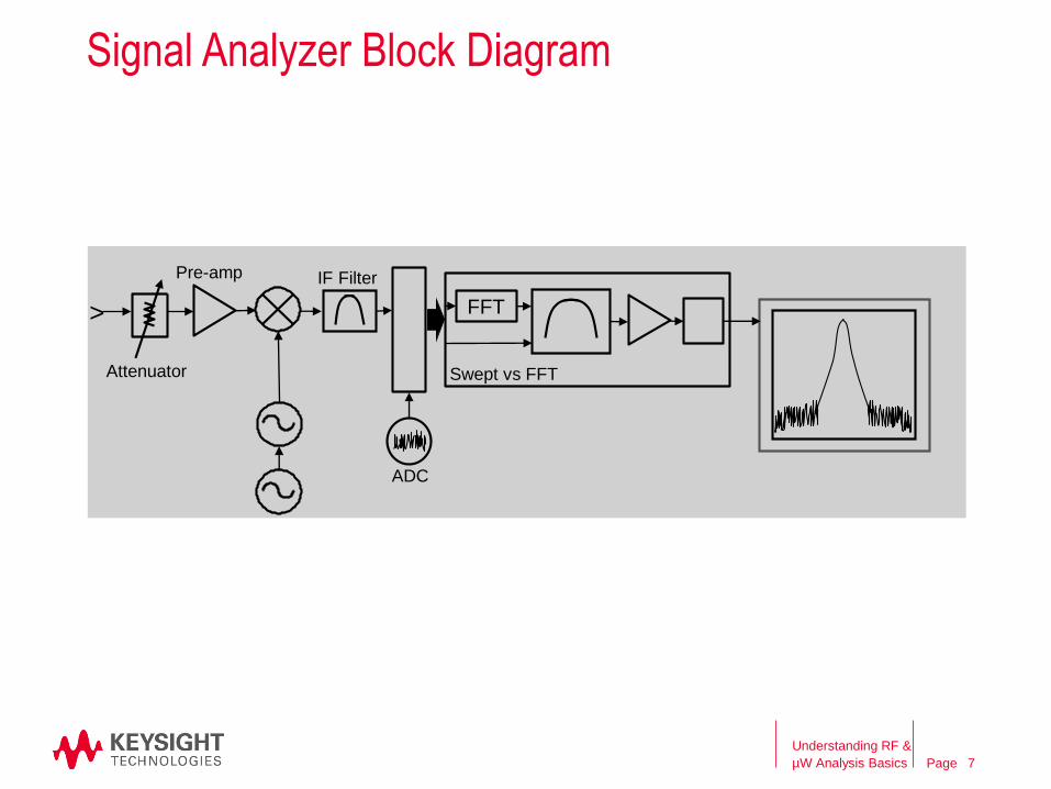
Swept vs FFT………………
Signal Analyzer Block Diagram
FFT>
Attenuator
Pre-amp IF Filter
ADC
Understanding RF &
µW Analysis Basics 7
Page
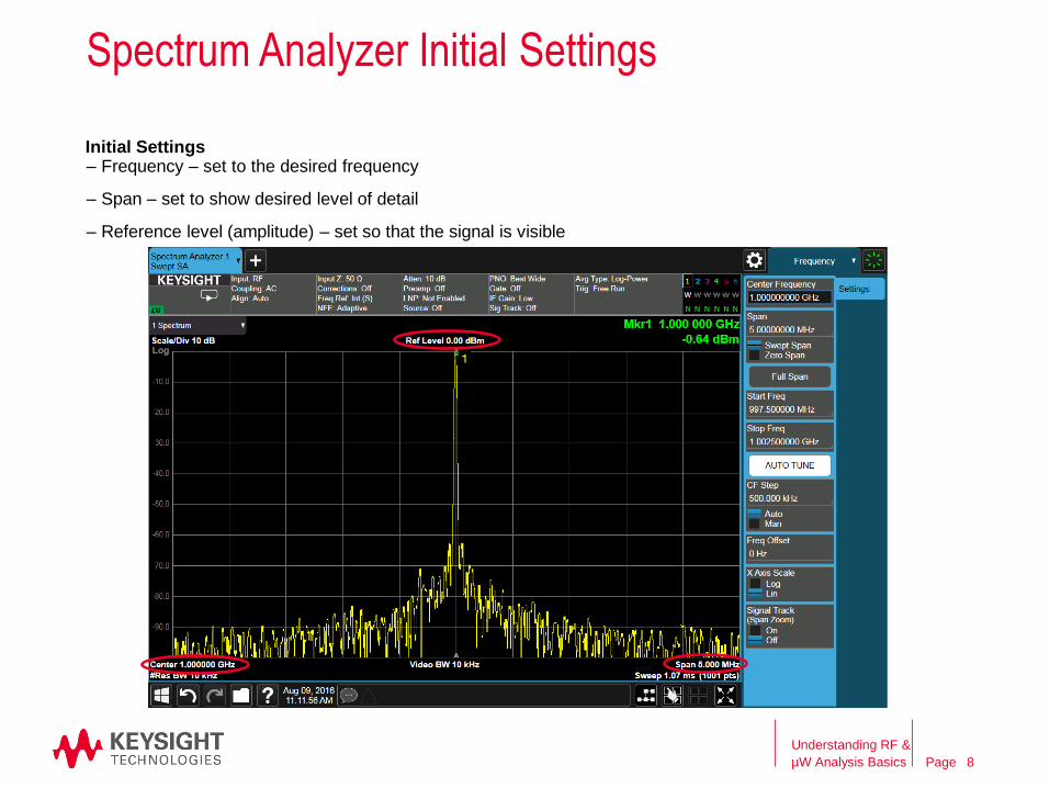
Spectrum Analyzer Initial Settings
Initial Settings– Frequency – set to the desired frequency
– Span – set to show desired level of detail
– Reference level (amplitude) – set so that the signal is visible
Understanding RF &
µW Analysis Basics 8
Page
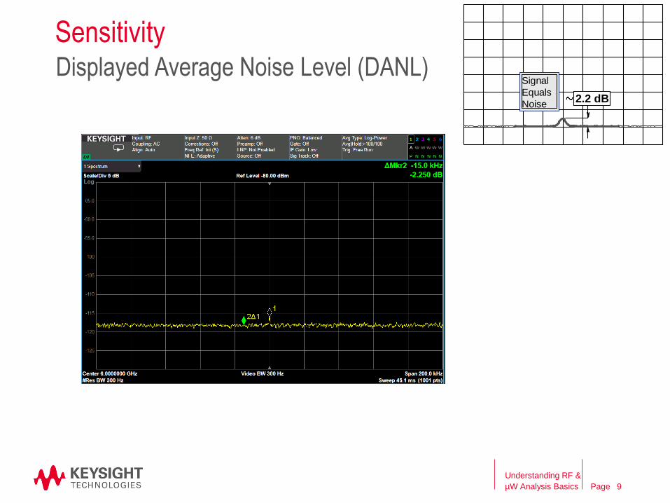
SensitivityDisplayed Average Noise Level (DANL)
2.2 dB
Signal
Equals
Noise
Understanding RF &
µW Analysis Basics 9
Page
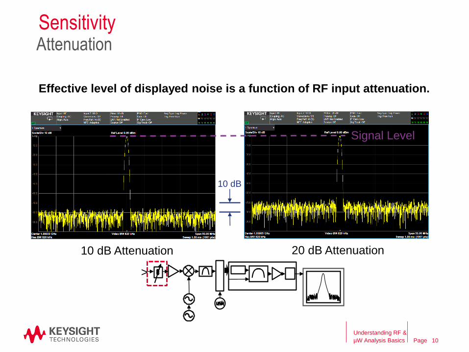
Sensitivity
Effective level of displayed noise is a function of RF input attenuation.
10 dB
10 dB Attenuation 20 dB Attenuation
Signal Level
Attenuation
Understanding RF &
µW Analysis Basics
>
10
Page
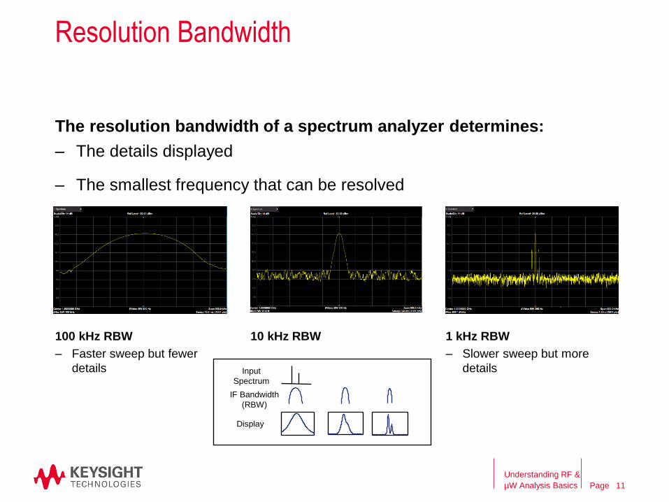
100 kHz RBW
Resolution Bandwidth
The resolution bandwidth of a spectrum analyzer determines:
– The details displayed
– The smallest frequency that can be resolved
10 kHz RBW 1 kHz RBW
– Faster sweep but fewer
details
– Slower sweep but more
details
Display
Input
Spectrum
IF Bandwidth
(RBW)
Understanding RF &
µW Analysis Basics 11
Page
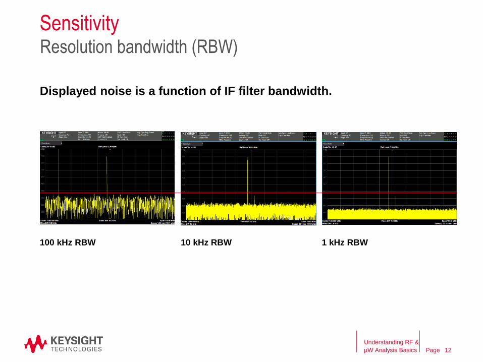
100 kHz RBW
Sensitivity
Displayed noise is a function of IF filter bandwidth.
10 kHz RBW 1 kHz RBW
Resolution bandwidth (RBW)
Understanding RF &
µW Analysis Basics 12
Page
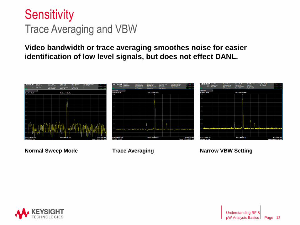
Normal Sweep Mode
Sensitivity
Video bandwidth or trace averaging smoothes noise for easier
identification of low level signals, but does not effect DANL.
Trace Averaging Narrow VBW Setting
Trace Averaging and VBW
Understanding RF &
µW Analysis Basics 13
Page
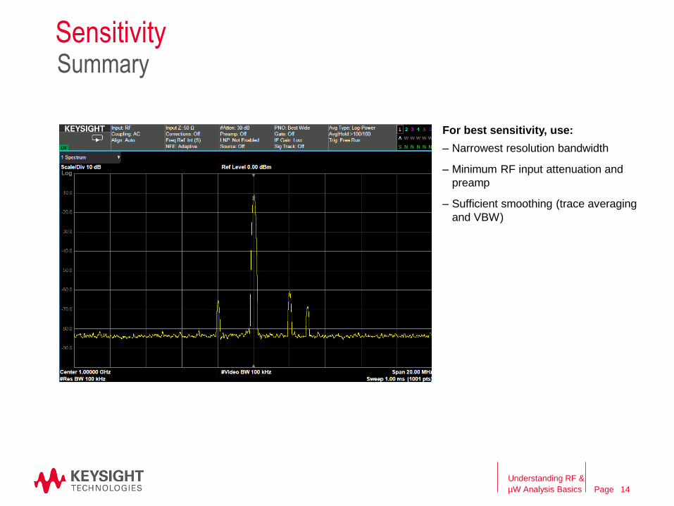
SensitivitySummary
For best sensitivity, use:
– Narrowest resolution bandwidth
– Minimum RF input attenuation and
preamp
– Sufficient smoothing (trace averaging
and VBW)
Understanding RF &
µW Analysis Basics 14
Page
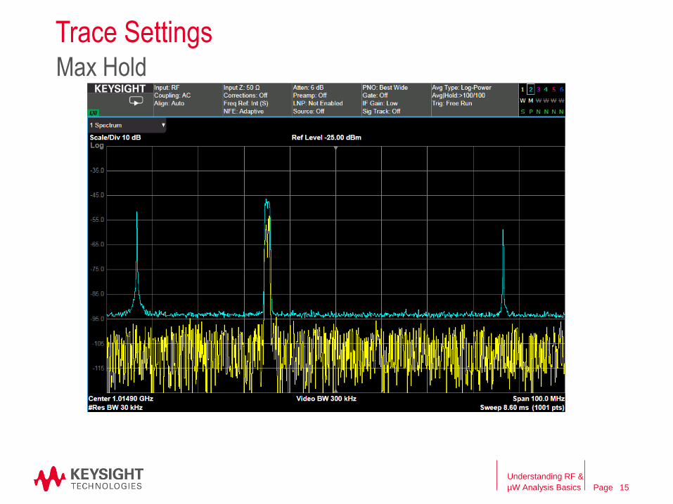
Trace SettingsMax Hold
Understanding RF &
µW Analysis Basics 15
Page
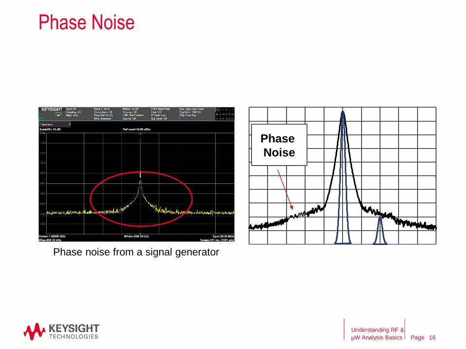
Phase Noise
Phase noise from a signal generator
Phase
Noise
Understanding RF &
µW Analysis Basics 16
Page
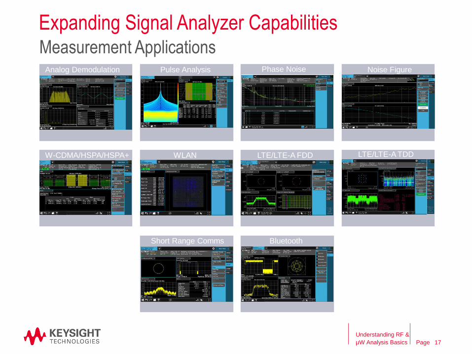
Expanding Signal Analyzer Capabilities
Understanding RF &
µW Analysis Basics 17
Measurement ApplicationsN9063A Analog Analog Demodulation Pulse Analysis Phase Noise Noise Figure
W-CDMA/HSPA/HSPA+ WLAN LTE/LTE-A FDD LTE/LTE-A TDD
Short Range Comms Bluetooth
Page
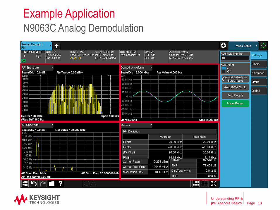
Example Application
Understanding RF &
µW Analysis Basics
N9063C Analog Demodulation
18
Page
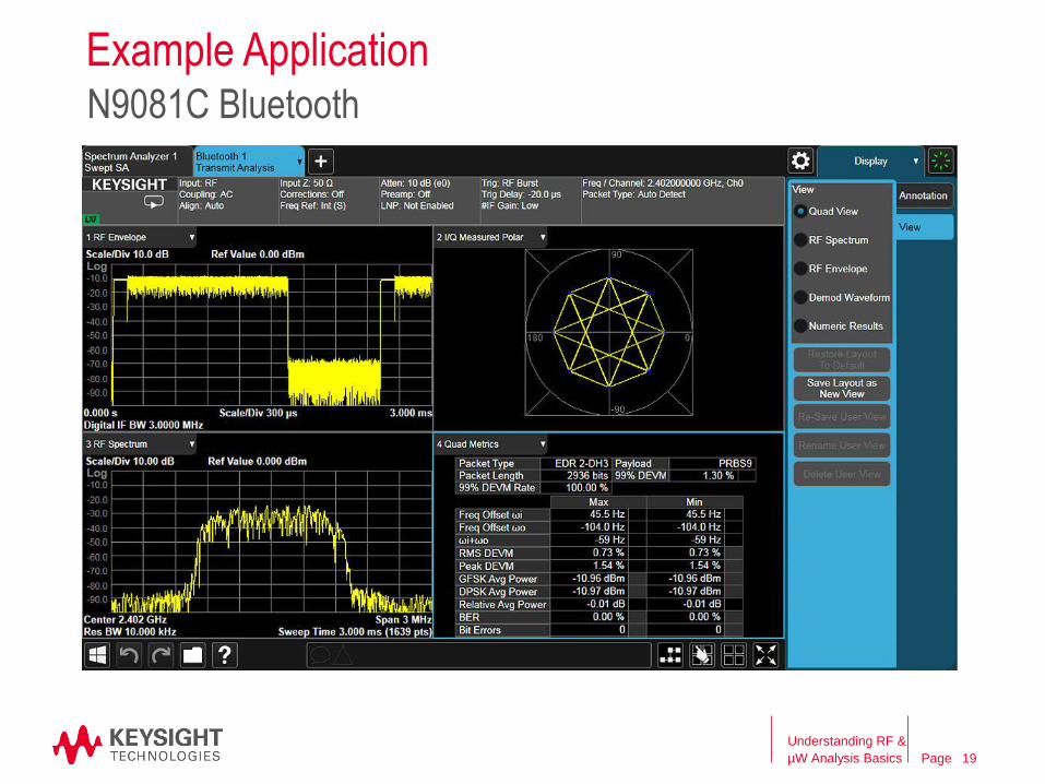
Example Application
Understanding RF &
µW Analysis Basics
N9081C Bluetooth
19
Page
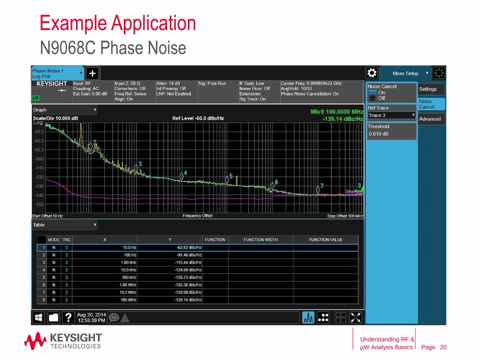
Example Application
Understanding RF &
µW Analysis Basics
N9068C Phase Noise
20
PageAgenda
RF Signal Analyzer Overview & Basic Settings
• Overview of signal analysis – measurements, instrument block diagram
• Initial settings to capture a signal – frequency, span, reference level
• Improving the quality of your measurement – averaging, RBW, sweep time
• How DANL, sensitivity, and phase noise can impact a measurement
– Signal Generators
• Overview of signal generation – signals, instrument block diagram
– Signal Analyzer & Signal Generator Applications
– Wrap-up and Q&A
Understanding RF &
µW Analysis Basics 21
Page
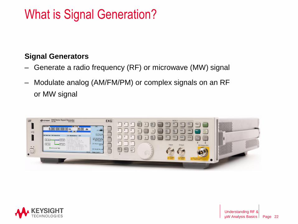
What is Signal Generation?
Signal Generators
– Generate a radio frequency (RF) or microwave (MW) signal
– Modulate analog (AM/FM/PM) or complex signals on an RF
or MW signal
Understanding RF &
µW Analysis Basics 22
Page
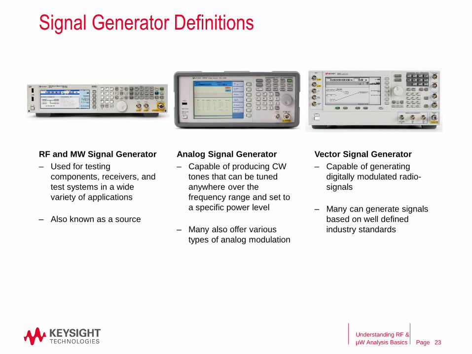
RF and MW Signal Generator
Signal Generator Definitions
Analog Signal Generator Vector Signal Generator
– Used for testing
components, receivers, and
test systems in a wide
variety of applications
– Also known as a source
– Capable of producing CW
tones that can be tuned
anywhere over the
frequency range and set to
a specific power level
– Many also offer various
types of analog modulation
– Capable of generating
digitally modulated radio-
signals
– Many can generate signals
based on well defined
industry standards
Understanding RF &
µW Analysis Basics 23
Page
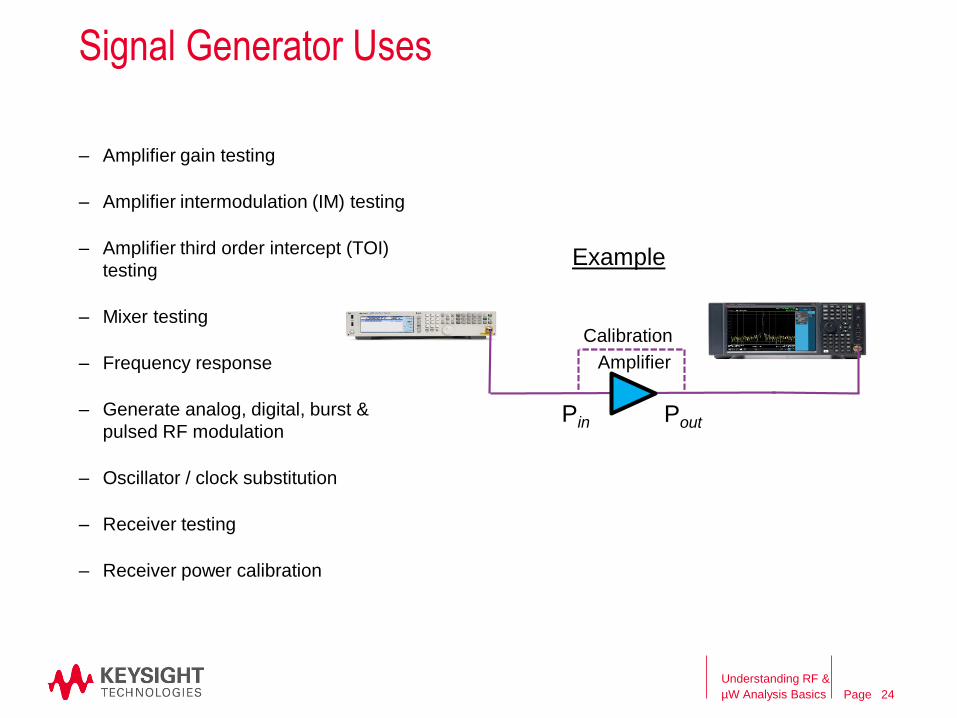
Signal Generator Uses
– Amplifier gain testing
– Amplifier intermodulation (IM) testing
– Amplifier third order intercept (TOI)
testing
– Mixer testing
– Frequency response
– Generate analog, digital, burst &
pulsed RF modulation
– Oscillator / clock substitution
– Receiver testing
– Receiver power calibration
Amplifier
Calibration
Pin Pout
Example
Understanding RF &
µW Analysis Basics 24
Page
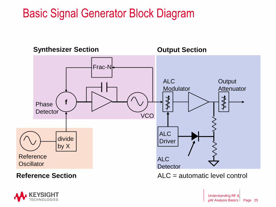
Basic Signal Generator Block Diagram
Frac-N
divide
by X
ALC
Modulator
ALC
Driver
ALC
Detector
Output
Attenuator
ALC = automatic level controlReference Section
Output SectionSynthesizer Section
f
Reference
Oscillator
Phase
DetectorVCO
Understanding RF &
µW Analysis Basics 25
Page
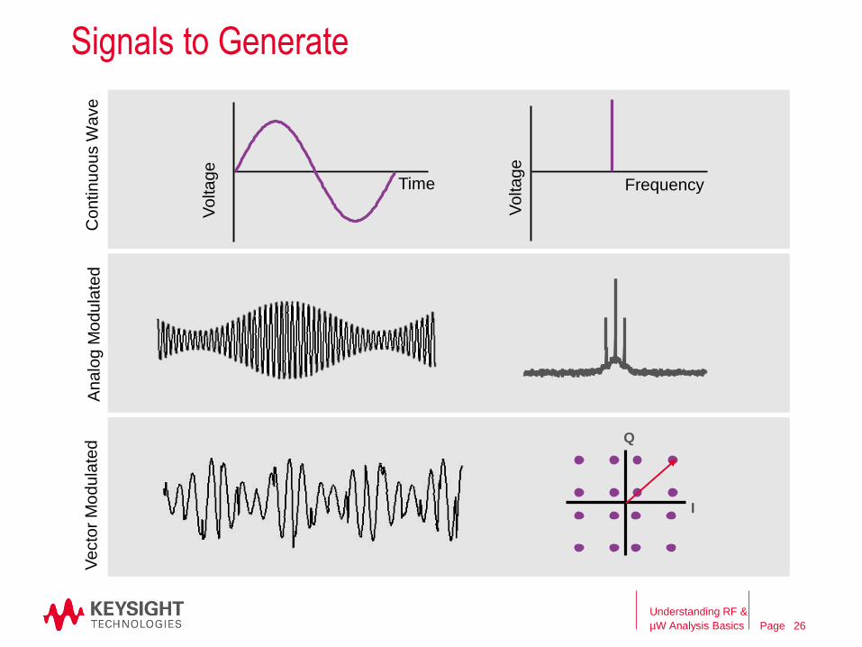
Signals to Generate
Understanding RF &
µW Analysis Basics
Voltage
Frequency
Voltage
Time
I
Q
26
Continuo
us W
ave
Analo
g M
odu
late
dV
ecto
r M
od
ula
ted
Page
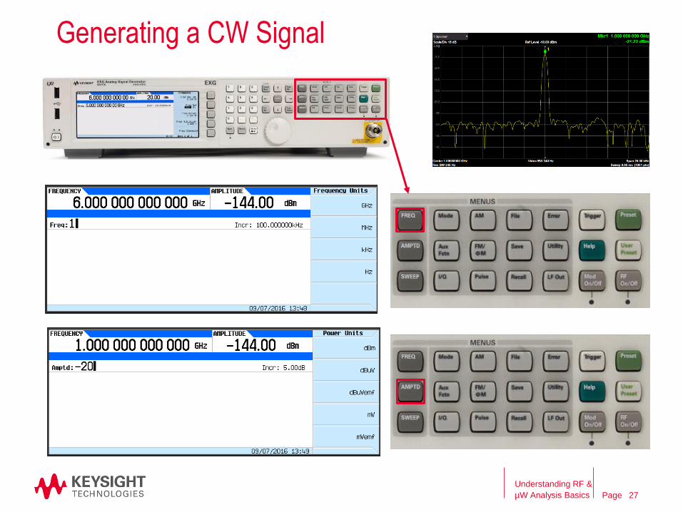
Generating a CW Signal
Understanding RF &
µW Analysis Basics 27
Page
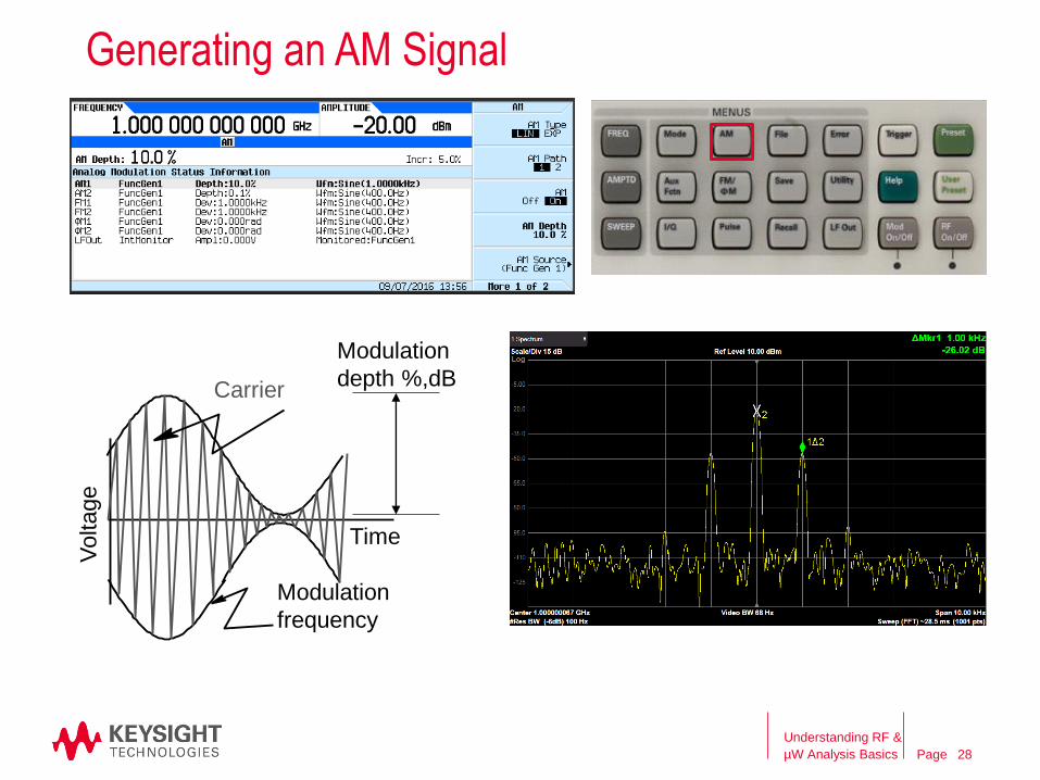
Generating an AM SignalV
oltage
Time
Carrier
Modulation
frequency
Modulation
depth %,dB
Understanding RF &
µW Analysis Basics 28
Page
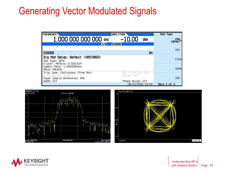
Generating Vector Modulated Signals
Understanding RF &
µW Analysis Basics 29
Page
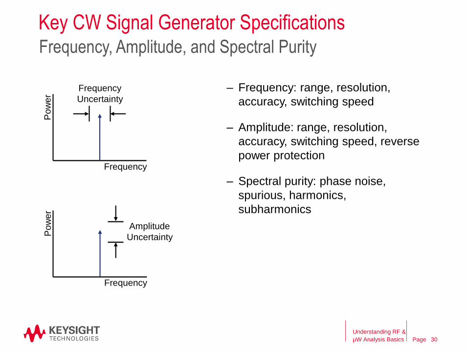
Key CW Signal Generator Specifications
– Frequency: range, resolution,
accuracy, switching speed
– Amplitude: range, resolution,
accuracy, switching speed, reverse
power protection
– Spectral purity: phase noise,
spurious, harmonics,
subharmonics
Frequency, Amplitude, and Spectral Purity
Frequency
Pow
er
Frequency
Uncertainty
Frequency
Pow
er
Amplitude
Uncertainty
Understanding RF &
µW Analysis Basics 30
Page
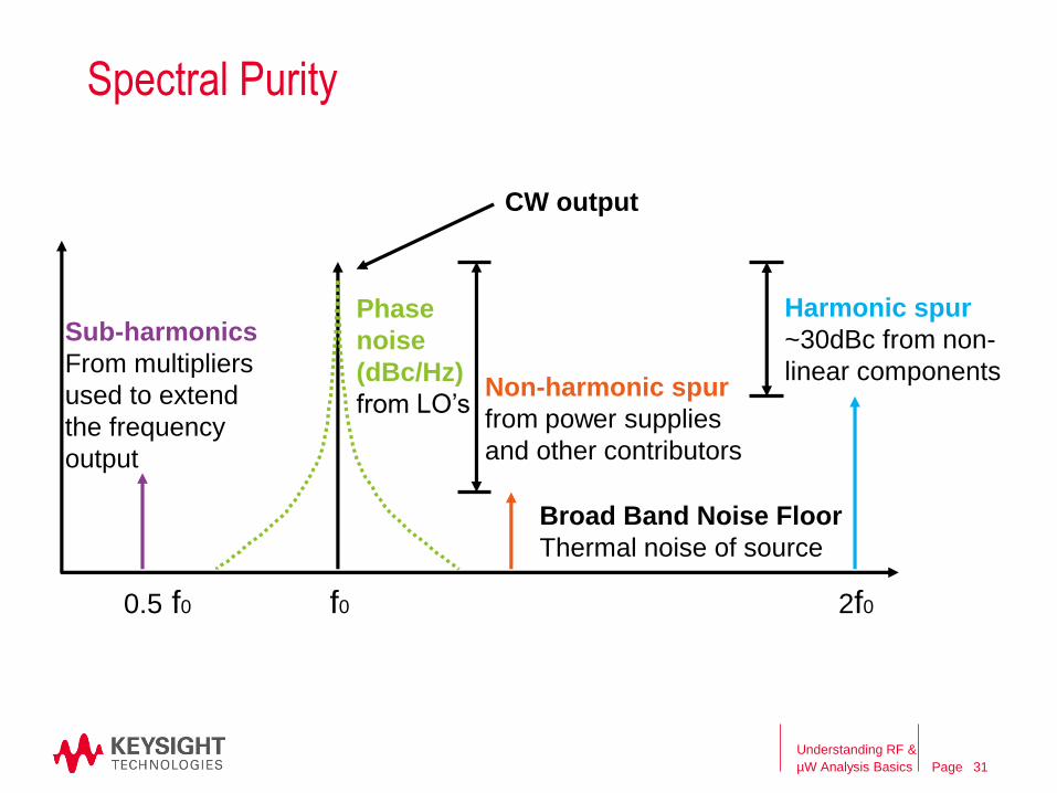
Spectral Purity
Non-harmonic spur
from power supplies
and other contributors
Harmonic spur
~30dBc from non-
linear components
CW output
Phase
noise
(dBc/Hz)
from LO’s
0.5 f0 f0 2f0
Sub-harmonics
From multipliers
used to extend
the frequency
output
Broad Band Noise Floor
Thermal noise of source
Understanding RF &
µW Analysis Basics 31
PageAgenda
RF Signal Analyzer Overview & Basic Settings
• Overview of signal analysis – measurements, instrument block diagram
• Initial settings to capture a signal – frequency, span, reference level
• Improving the quality of your measurement – averaging, RBW, sweep time
• How DANL, sensitivity, and phase noise can impact a measurement
Signal Generators
• Overview of signal generation – signals, instrument block diagram
– Signal Analyzer & Signal Generator Applications
– Wrap-up and Q&A
Understanding RF &
µW Analysis Basics 32
Page
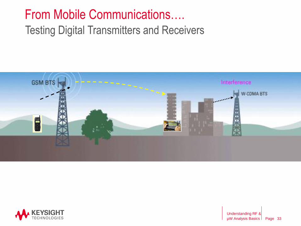
From Mobile Communications….Testing Digital Transmitters and Receivers
Understanding RF &
µW Analysis Basics 33
Page
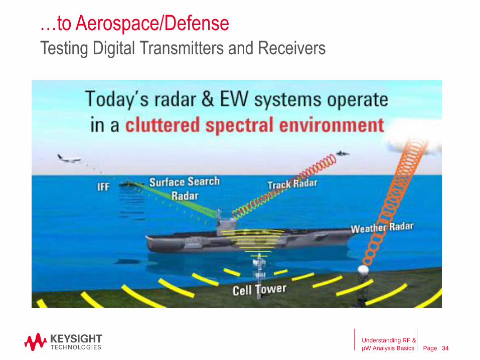
…to Aerospace/DefenseTesting Digital Transmitters and Receivers
Understanding RF &
µW Analysis Basics 34
Page
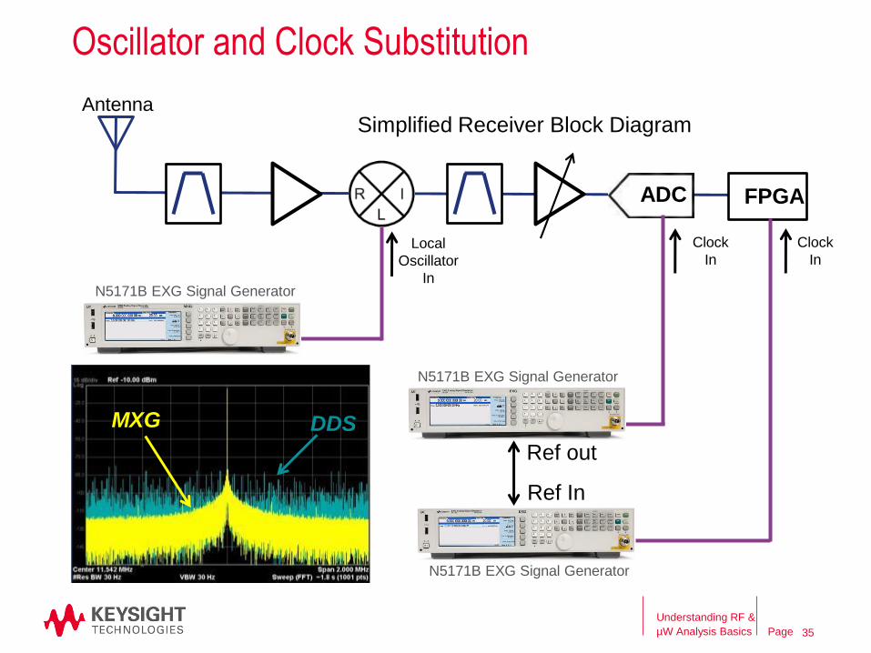
ADC FPGA
Antenna
Local
Oscillator
In
Clock
In
Clock
In
Simplified Receiver Block Diagram
Ref In
Ref out
DDSMXG
Oscillator and Clock Substitution
Understanding RF &
µW Analysis Basics 35
N5171B EXG Signal Generator
N5171B EXG Signal Generator
N5171B EXG Signal Generator
Page
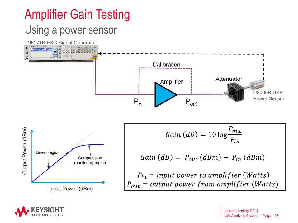
Amplifier Gain TestingUsing a power sensor
Amplifier
Calibration
Pin Pout
U2000B USB
Power Sensor
Attenuator
N5171B EXG Signal Generator
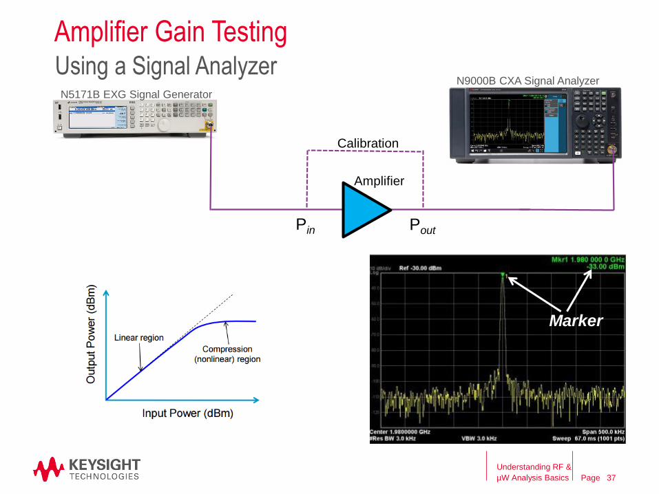
𝐺𝑎𝑖𝑛 𝑑𝐵 = 10 log𝑃𝑜𝑢𝑡𝑃𝑖𝑛
𝐺𝑎𝑖𝑛 𝑑𝐵 = 𝑃𝑜𝑢𝑡 𝑑𝐵𝑚 − 𝑃𝑖𝑛 (𝑑𝐵𝑚)
𝑃𝑖𝑛 = 𝑖𝑛𝑝𝑢𝑡 𝑝𝑜𝑤𝑒𝑟 𝑡𝑜 𝑎𝑚𝑝𝑙𝑖𝑓𝑖𝑒𝑟 𝑊𝑎𝑡𝑡𝑠𝑃𝑜𝑢𝑡 = 𝑜𝑢𝑡𝑝𝑢𝑡 𝑝𝑜𝑤𝑒𝑟 𝑓𝑟𝑜𝑚 𝑎𝑚𝑝𝑙𝑖𝑓𝑖𝑒𝑟 (𝑊𝑎𝑡𝑡𝑠)
Understanding RF &
µW Analysis Basics 36
Page
Amplifier Gain Testing
Understanding RF &
µW Analysis Basics
Using a Signal Analyzer
Amplifier
Calibration
Pin Pout
N5171B EXG Signal Generator
Marker
N9000B CXA Signal Analyzer
37
Page
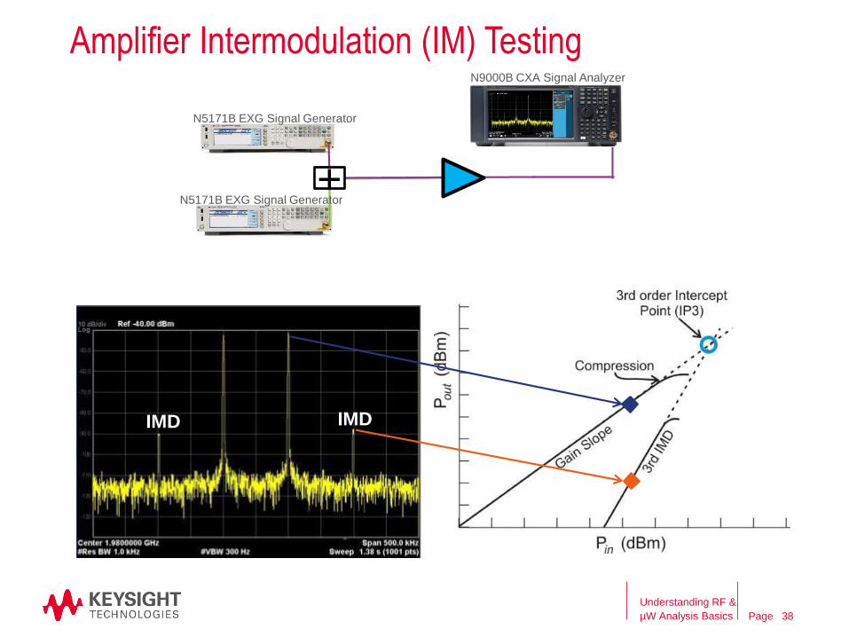
Amplifier Intermodulation (IM) Testing
IMD IMD
+
Understanding RF &
µW Analysis Basics 38
N9000B CXA Signal Analyzer
N5171B EXG Signal Generator
N5171B EXG Signal Generator

Page
Amplifier Intermodulation (IM) Testing
Amplifier
Pin Pout
N5171B EXG Signal Generator
N5171B EXG Signal Generator
+Combiner
Input
Output IMD IMD
N9000B CXA Signal Analyzer
Understanding RF &
µW Analysis Basics 39
Page
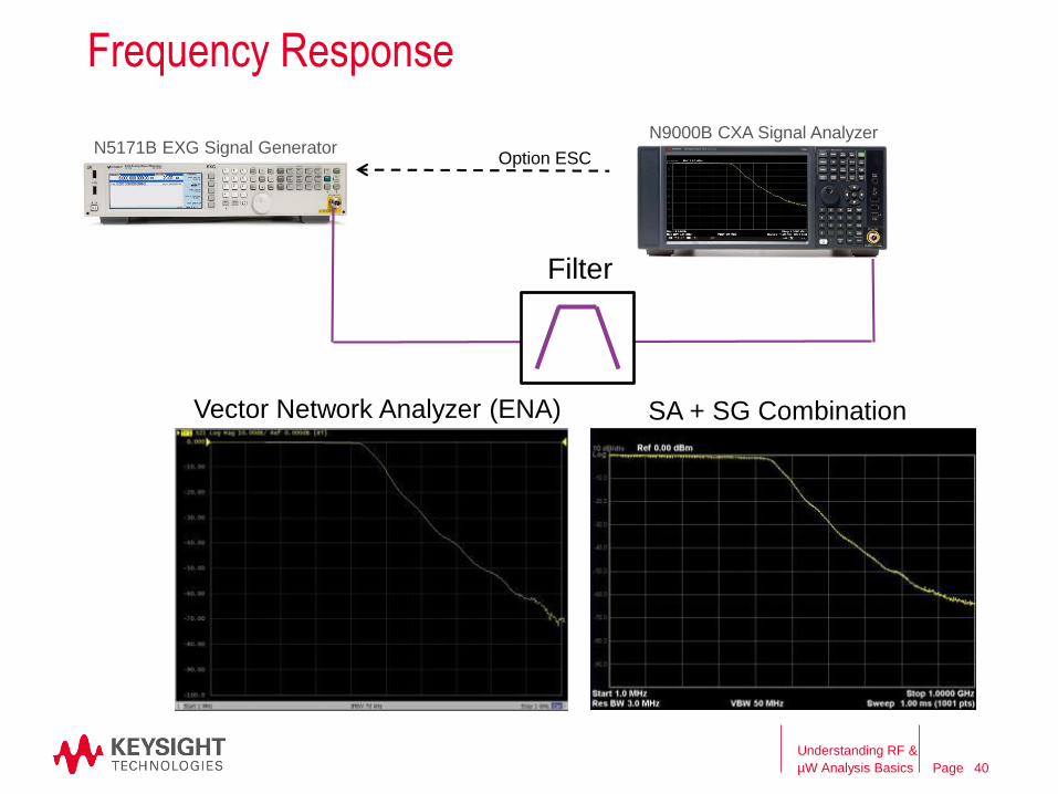
N5171B EXG Signal GeneratorN9000B CXA Signal Analyzer
Filter
Option ESC
Vector Network Analyzer (ENA) SA + SG Combination
Frequency Response
Understanding RF &
µW Analysis Basics 40
Page
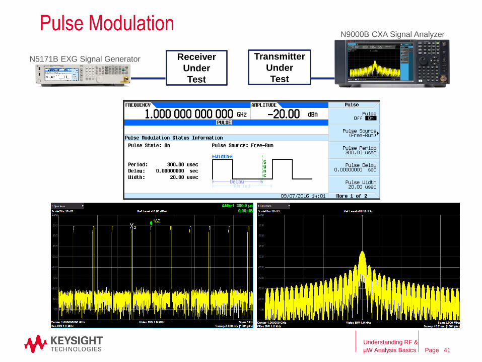
Receiver
Under
Test
Pulse Modulation
Transmitter
Under
Test
Understanding RF &
µW Analysis Basics 41
N5171B EXG Signal Generator
N9000B CXA Signal Analyzer
Page
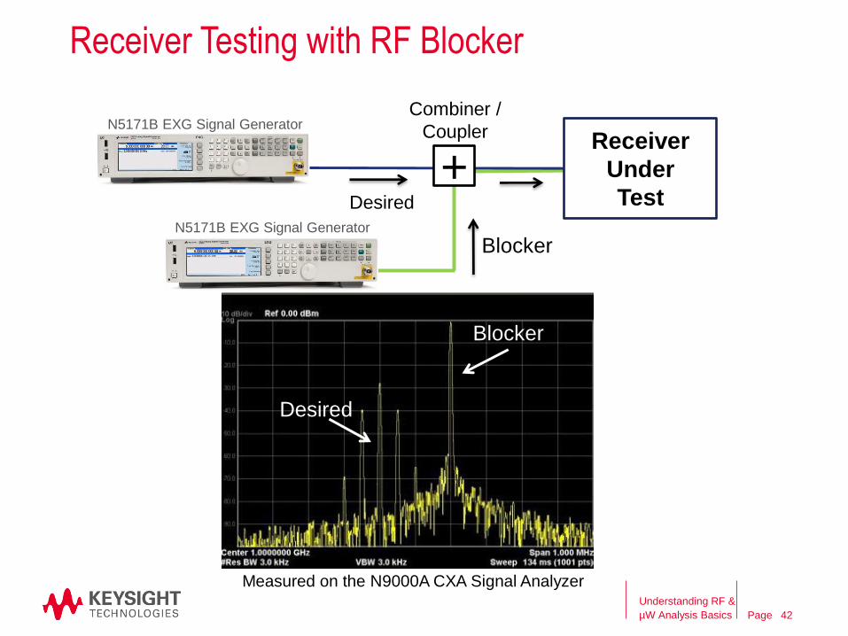
N5171B EXG Signal Generator
Receiver
Under
Test
Combiner /
Coupler
N5171B EXG Signal Generator
+
Blocker
Desired
Blocker
Desired
Measured on the N9000A CXA Signal Analyzer
Receiver Testing with RF Blocker
Understanding RF &
µW Analysis Basics 42
PageAgenda
RF Signal Analyzer Overview & Basic Settings
• Overview of signal analysis – measurements, instrument block diagram
• Initial settings to capture a signal – frequency, span, reference level
• Improving the quality of your measurement – averaging, RBW, sweep time
• How DANL, sensitivity, and phase noise can impact a measurement
Signal Generators
• Overview of signal generation – signals, instrument block diagram
Signal Analyzer & Signal Generator Applications
– Wrap-up and Q&A
Understanding RF &
µW Analysis Basics 43
Page
Resources
– More information on Signal Analyzers: Keysight.com/find/SA
– More information on Signal Generators: Keysight.com/find/SG
– Application Notes:
• Spectrum Analysis Basics
• Spectrum Analysis Amplitude and Frequency Modulation
• Digital Modulation in Communications Systems
Understanding RF &
µW Analysis Basics 44

Page
Keysight RF & MW Fundamentals eLearning Program
www.keysight.com/find/RFfundamentals
Get the best education quickly from trusted experts
eLearning modules • Cable & connector care• Transmission line fundamentals
Power measurement basics• Signal generator sources• General spectrum analysis• Network analysis
• State of the art, self-paced eLearning modules
• A strong foundation in RF & MW fundamentals includes:
the most important measurements
critical success factors for ensuring accuracy
how to get the most productivity and value from Keysight instruments
Understanding RF &
µW Analysis Basics 45
Page
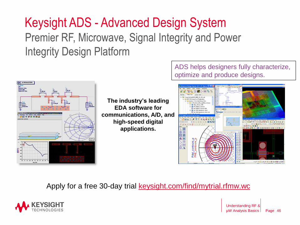
Keysight ADS - Advanced Design SystemPremier RF, Microwave, Signal Integrity and Power
Integrity Design PlatformADS helps designers fully characterize,
optimize and produce designs.
The industry’s leading
EDA software for
communications, A/D, and
high-speed digital
applications.
Apply for a free 30-day trial keysight.com/find/mytrial.rfmw.wc
Understanding RF &
µW Analysis Basics 46
Page
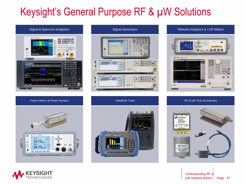
Keysight’s General Purpose RF & µW Solutions
Understanding RF &
µW Analysis Basics 47
Signal & Spectrum Analyzers Signal Generators Network Analyzers & LCR Meters
Power Meters & Power Sensors Handheld Tools RF & µW Test Accessories
Page
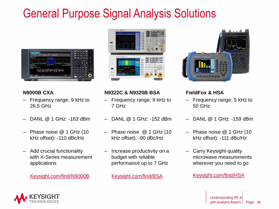
N9000B CXA
General Purpose Signal Analysis Solutions
Understanding RF &
µW Analysis Basics
N9322C & N9320B BSA FieldFox & HSA
– Frequency range: 9 kHz to
26.5 GHz
– DANL @ 1 GHz: -163 dBm
– Phase noise @ 1 GHz (10
kHz offset): -110 dBc/Hz
– Add crucial functionality
with X-Series measurement
applications
Keysight.com/find/N9000B
– Frequency range: 9 kHz to
7 GHz
– DANL @ 1 GHz: -152 dBm
– Phase noise @ 1 GHz (10
kHz offset): -90 dBc/Hz
– Increase productivity on a
budget with reliable
performance up to 7 GHz
Keysight.com/find/BSA
– Frequency range: 5 kHz to
50 GHz
– DANL @ 1 GHz: -159 dBm
– Phase noise @ 1 GHz (10
kHz offset): -111 dBc/Hz
– Carry Keysight-quality
microwave measurements
wherever you need to go
Keysight.com/find/HSA
48
Page
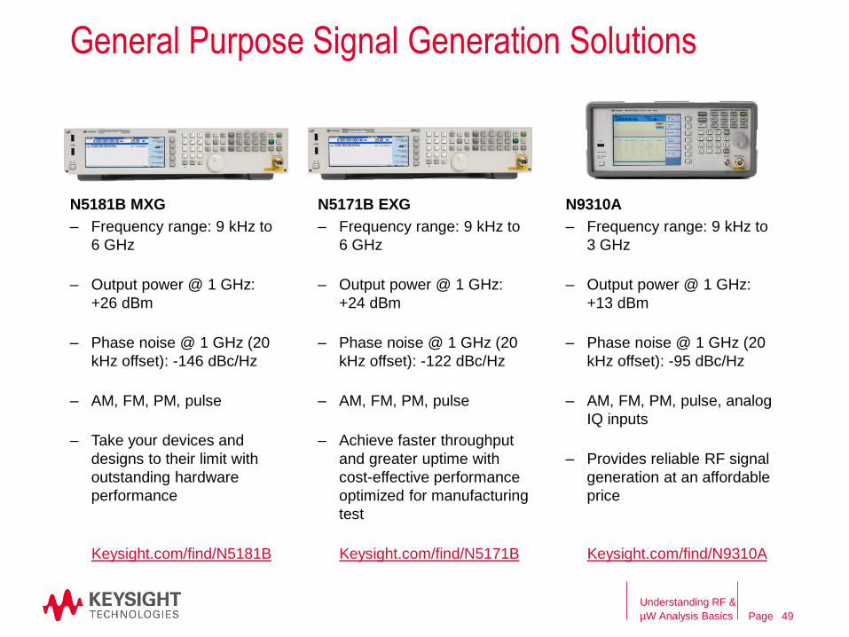
N5181B MXG
General Purpose Signal Generation Solutions
Understanding RF &
µW Analysis Basics
N5171B EXG N9310A
– Frequency range: 9 kHz to
6 GHz
– Output power @ 1 GHz:
+26 dBm
– Phase noise @ 1 GHz (20
kHz offset): -146 dBc/Hz
– AM, FM, PM, pulse
– Take your devices and
designs to their limit with
outstanding hardware
performance
Keysight.com/find/N5181B
– Frequency range: 9 kHz to
6 GHz
– Output power @ 1 GHz:
+24 dBm
– Phase noise @ 1 GHz (20
kHz offset): -122 dBc/Hz
– AM, FM, PM, pulse
– Achieve faster throughput
and greater uptime with
cost-effective performance
optimized for manufacturing
test
Keysight.com/find/N5171B
– Frequency range: 9 kHz to
3 GHz
– Output power @ 1 GHz:
+13 dBm
– Phase noise @ 1 GHz (20
kHz offset): -95 dBc/Hz
– AM, FM, PM, pulse, analog
IQ inputs
– Provides reliable RF signal
generation at an affordable
price
Keysight.com/find/N9310A
49
Page
Switches
Attenuators
Amplifier
Waveguide Harmonic Mixers
Noise Sources
Adapters & Connectors
Attenuator/Switch Driver
DC Block
Detector
Directional Bridge
Directional Coupler
Frequency Meter
Impedance Matching Pad
Power Divider
Power Limiter
Power Splitter
PXI Module
Termination (Loads)
Waveguide Accessories
RF Probes
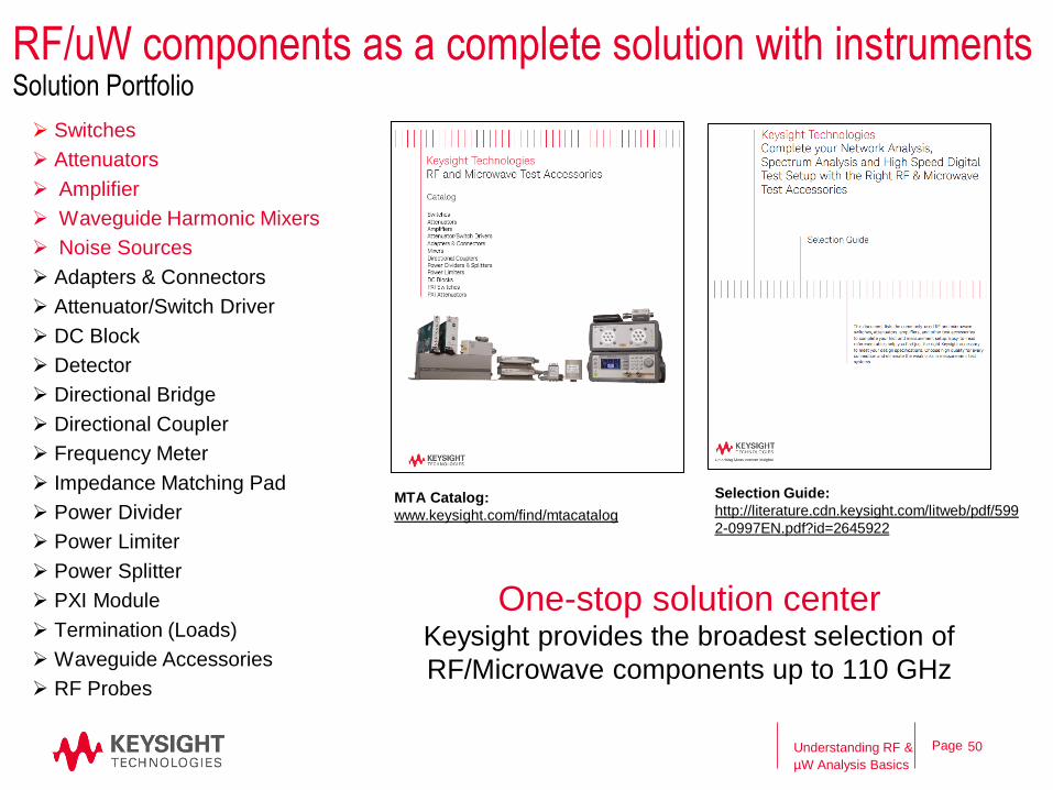
One-stop solution center Keysight provides the broadest selection of
RF/Microwave components up to 110 GHz
Selection Guide:
http://literature.cdn.keysight.com/litweb/pdf/599
2-0997EN.pdf?id=2645922
MTA Catalog:
www.keysight.com/find/mtacatalog
RF/uW components as a complete solution with instrumentsSolution Portfolio
Understanding RF &
µW Analysis Basics
50
Question & Answer Session
Kimberly Cassacia
Product Line Brand Manager
Keysight Technologies