rf range reference guide. 900 mhz - oleumtech rf range data chart (transmitter to gateway) 2....
TRANSCRIPT

TABLE OF CONTENT
1. Maximum RF Range Data Chart
(Transmitter to Gateway)
2. Maximum RF Range Data Chart
(Gateway to Gateway)
3. Cable Attenuation/Signal Loss
4. Non-Directional vs Directional Antenna
5. RSSI & Other Helpful Information
6. Antenna Specifications
TR
AN
SM
IT
TE
R
RF Range Reference Guide. 900 MHzA
PP
LI
CA
TI
ON
N
OT
E
ISO9001
OleumTech
REGISTERED COMPANY
ISO9001
©2015 OleumTech Corporation. All rights reserved. OleumTech and BreeZ are registered trademarks of OleumTech Corporation in the United States. Speci�cations, design, and product descriptionssubject to change without notice. This device contains proprietary intellectual property protected by US Patent #6967589. Document ID: AN-1037-001_E
CorporationMADE IN USA
toll-free 866.508.8586 │ ph 949.305.9009 │ fx 949.305.9010 │ oleumtech.com │ [email protected]

*Field tested with clear line of sight with antennas raised to 9 to 15 ft above ground at sea level (tested for point-to-point values only). Actual wireless RF range may vary depending on location, antenna and cable setup, and line of sight. Graphs not to scale.**500 mW and 1000 mW Tx Power Settings on the Wireless Gateway are dedicated for long-range RF communications with other Wireless Gateways (Peer-to-Peer applications). Use lower Tx Power Settings when possible to conserve power.
900 MHz @ 9600 bit RATE
YAGI, 3-ELEMENT, 6 db TRANSMITTER TX POWER GATEWAY TX POWER RF RANGE*
10mW 1mw Up to 7500 ft / 2.3 Km
10mW 10mw Up to 7500 ft / 2.3 Km
10mW 100mw Up to 7500 ft / 2.3 Km
10mW 500mw** Up to 7500 ft / 2.3 Km
10mW 1000mw** Up to 7500 ft / 2.3 Km
OMNI, 25-INCH, 3 dB TRANSMITTER TX POWER GATEWAY TX POWER RF RANGE*
10mW 1mw Up to 7000 ft / 2.1 Km
10mW 10mw Up to 7000 ft / 2.1 Km
10mW 100mw Up to 7000 ft / 2.1 Km
10mW 500mw** Up to 7000 ft / 2.1 Km
10mW 1000mw** Up to 7000 ft / 2.1 Km
BULKHEAD ANTENNA, 3 dB TRANSMITTER TX POWER GATEWAY TX POWER RF RANGE*
10mW 1mw Up to 5000 ft / 1.5 Km
10mW 10mw Up to 5000 ft / 1.5 Km
10mW 100mw Up to 5000 ft / 1.5 Km
10mW 500mw** Up to 5000 ft / 1.5 Km
10mW 1000mw** Up to 5000 ft / 1.5 Km
“Transmit” “Receive”
“Transmit” “Receive”
“Transmit” “Receive”
SA1000-AK1 with 24” CableSA1000-AK4 with 48” Cable
SA1000-AK2 with 24” CableSA1000-AK5 with 48” Cable
SA1000-AK3 3-Element with 24” CableSA1000-AK6 6-Element with 24” Cable
Transmitter to GatewayM A X I M U M R F R A N G E

YAGI, 6-ELEMENT, 6 db GATEWAY A TX POWER GATEWAY B TX POWER RF RANGE*
1mw 1mw Up to 1.5 miles / 2.4 Km
10mw 10mw Up to 5 miles / 8.1 Km
100mw 100mw Up to 15 miles / 24.1 Km
500mw 500mw Up to 30 miles / 48.3 Km
1000mw 1000mw Up to 40 miles / 64.4 Km
*Based on theoretical RF Link Budget with clear line of sight using 6 dB Yagi Antenna, -100 dBm Rx Sensitivity, and 900 MHz Frequency with 9600 bitRate. Fading margin, body loss, polarization mismatch, and other losses excluded from consideration. Actual wireless RF range may vary depending on location, antenna setup, and line of sight.
“Transmit & Receive” “Transmit & Receive”
SA1000-AK6 with 24” Cable
Gateway to GatewayM A X I M U M R F R A N G E
900 MHz @ 9600 bit RATE

RG-174 TypeN Male to MMCX ConnectionAvailable in 6, 24, 35, and 48 inch lengths.
ATX-195 TypeN Male to N Male ConnectionAvailable in 15 ft length.
LMR-400 Type (Low-Loss)N Male to N Male ConnectionAvailable in 30, 50, 75, and 100 ft lengths.
CABLE TYPE 1 ft / 0.3 m 10 ft / 3 m 25 ft / 7.6 m 50 ft / 15.2 m 100 ft / 30.5 m 200 ft / 61 m
RG-174 0.3 dB 2.8 dB 7.0 dB 14.0 dB 27.9 dB 55.8 dB
ATX-195 0.1 dB 1.1 dB 2.8 dB 5.6 dB 11.1 dB 22.2 dB
LMR-400 0.04 dB 0.4 dB 0.1 dB 2.0 dB 3.9 dB 7.8 dB
ATTENUATION / COAX CABLE SIGNAL LOSS IN dB
900 MHzC A B L E A T T E N U A T I O N

OMNI ANTENNA
The Omni antenna is designed to be usable from any direction (hence its name). As a result, it doesn´t have the straight-line range of the Yagi, but because it distributes its radio energy in more of a donut shape, be sure you have the main part is oriented straight up and down, with the feed line at the bottom.
Omni antennas should be used for receiving data from multiple units scattered around the field (point-to-multipoint).
YAGI ANTENNA
In order to have "Gain,” a Yagi antenna takes its signal strength from all around and points it in one general direction. This makes the Yagi "Directional.“ That means that it has to be oriented one particular way so the radio signal is pointed toward the antenna of the device with which you want to communicate.
Yagi antennas should be used for relaying data to another unit (point-to-point only).
Omni Antenna
1. Position the antenna in the mounting bracket.2. Align the antenna so that the metal base is even with or above the top of the mast tubing.3. Tighten the mounting bracket until the antenna is secure on the mast.4. Connect the antenna cable to the antenna.
Yagi Antenna
1. Assemble Yagi antenna if needed.2. Position the antenna in the mounting bracket.3. Align the antenna so that the metal base of the mounting bracket is even with or above the top of the mast tubing.4. Point the antenna to its corresponding receiver.5. Tighten the mounting bracket until the antenna is secure on the mast.6. Connect the antenna cable to the antenna.
ANTENNA INSTALLATION
UP
DOWN
RADIOENERGY
GROUND RADIALSANGLED DOWNWARD
RADIOENERGY
DIRECTION OF RADIOENERGY
Omni vs. Yagi AntennaA N T E N N A T Y P E S
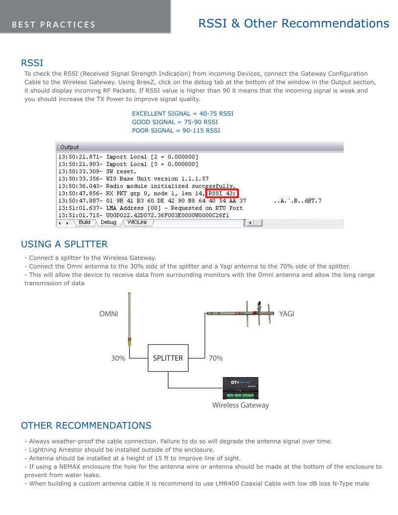
RSSITo check the RSSI (Received Signal Strength Indication) from incoming Devices, connect the Gateway Configuration Cable to the Wireless Gateway. Using BreeZ, click on the debug tab at the bottom of the window in the Output section, it should display incoming RF Packets. If RSSI value is higher than 90 it means that the incoming signal is weak and you should increase the TX Power to improve signal quality.
USING A SPLITTER- Connect a splitter to the Wireless Gateway. - Connect the Omni antenna to the 30% side of the splitter and a Yagi antenna to the 70% side of the splitter. - This will allow the device to receive data from surrounding monitors with the Omni antenna and allow the long range transmission of data
- Always weather-proof the cable connection. Failure to do so will degrade the antenna signal over time.- Lightning Arrestor should be installed outside of the enclosure. - Antenna should be installed at a height of 15 ft to improve line of sight. - If using a NEMAX enclosure the hole for the antenna wire or antenna should be made at the bottom of the enclosure to prevent from water leaks.- When building a custom antenna cable it is recommend to use LMR400 Coaxial Cable with low dB loss N-Type male
OTHER RECOMMENDATIONS
EXCELLENT SIGNAL = 40-75 RSSI GOOD SIGNAL = 75-90 RSSIPOOR SIGNAL = 90-115 RSSI
Wireless Gateway
SPLITTER
OMNI YAGI
30% 70%
RSSI & Other RecommendationsB E S T P R A C T I C E S

ohm
Electrical Properties
Frequency Range: 902 -928MHzImpedance: 50 VSWR: <2.0:1Gain: 3dBiRadiation: OmniPolarization: VerticalMax Power 100WTermination N-Female
Mechanical Properties
Height: 2.30"Weight 6.0 ozOperating Temperature: -30°C to +80 °CInstallation Torque 4-6ft*lb (P -Mount)Color: Black (TRAB) or White (TRA) RoHS Compliant: Yes
BULKHEAD OMNI ANTENNA TRA(B)9023NP (902-928 MHz)
Features• True Field Diversity design ensures
uninterrupted transmissions in urban canyons and rural drop off areas
• Omni outperforms a 3dB whip in many applications
• U.S. Patent Nos. 5,977,931 – 6,292,156and 7,209,096
Markets• Cell
• GSM and PCS
• WiFi
• 802.11
• Bluetooth wireless applications
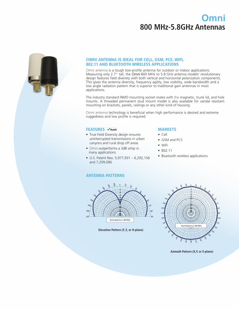
OMNI antenna is ideal For Cell, GsM, PCe, WiFi, 802.11 and Bluetooth Wireless aPPliCationsOmni antenna is a tough low-profile antenna for outdoor or indoor applications. Measuring only 2.7” tall, the Omni 800 MHz to 5.8 GHz antenna models’ revolutionary design features field diversity with both vertical and horizontal polarization components. This gives the antenna diversity, frequency agility, low visibility, wide bandwidth and a low angle radiation pattern that is superior to traditional gain antennas in most applications.
The industry standard NMO mounting socket mates with the magnetic, trunk lid, and hole mounts. A threaded permanent stud mount model is also available for vandal resistant mounting on brackets, panels, ceilings or any other kind of housing.
Omni antenna technology is beneficial when high performance is desired and extreme ruggedness and low profile is required.
antenna Patterns
Omni800 MHz-5.8GHz Antennas
0
0
80°
70°
60°
50°
40°
30°
20° 1
0°
350
°
340
°
330
° 3
20°
310°
300°
290°
28°
270°
90°
-2
-4-6-8
-10
-20
-30-40-50
Elevation Pattern (Y, Z, or H-plane)
0
80°
70°
60°
50°
40°
30°
20° 1
0°
350
340
°
330
° 3
20°
310°
300°
290°
280°
270°
260°
250°
240° 230°
220° 210° 200°
190°
180°
170°
160°
150° 140°
130°
120°
110°
100°
90°
-2
-4-6-8
-10
-20
-30-40-50
Azimuth Pattern (X,Y, or E-plane)

OMNI
800 MHz-5.8GHz Antennas
ELECTRICAL
VSWR < 2.1
Nominal Gain 3 dB-M.E.G.
Maximum Power 100 W
Nominal Impedance 50 Ω
Polarization Vertical & Horizontal
Pattern Omnidirectional
Half-Power Beamwidth(Elevation° x Azimuth°)
130° x 360°
Coaxial Cable Length & Type None
Terminations NMO Socket or, type N-female
sPeCiFiCations
MODEL DESCRIPTION
TRA8063 806-870 MHz 3 dB-MEG Omni ¾ NMO, White Radome
TRA8213 821-896 MHz 3 dB-MEG Omni ¾ NMO, White Radome
TRA8903 890-960 MHz 3 dB-MEG Omni ¾ NMO, White Radome
TRA9023 902-928 MHz 3 dB-MEG Omni ¾ NMO, White Radome
TRA18503 1.85 - 1.99 GHz 3dB-MEG Omni ¾ NMO, White Radome
TRA24003 2.4 – 2.5 GHz 3 dB-MEG Omni ¾ NMO, White Radome
TRA58003 4.9 – 6.0 GHz 3 dB-MEG Omni ¾ NMO, White Radome
TRADCAGPG - Drop ceiling antenna adaptor for P-mount Omni w/
6”x6”x0.016” ground plane
Sealtube3Heat shrink tubing 3”x1”DIA install
(use for jaw protector on installation wrench)
Model and orderinG inForMation
MECHANICAL
Color Black or White
Height (initially) 2¾”
Diameter 1.438”
Weight 0.173 lb
Material ABS
Mounting InformationNMO (PN: MB8, MAB8)
Sold Separately
Noise Suppressor
BlackHawk NS15351-35 VOLT, 15 AmpNoise Suppessor(Sold Separately)
Permanent Mounting Option:Please order by antenna model and insert letter “P” to indicate permanent mounting option (TRA8063P).
Add “B” to model number for black radome. Example: TRAB8063Add “P” to model number for Permanent Mount. Example: TRA8063P

Fiberglass OmnidirectiOnal antennas
Fg9023
electrical
Frequency Range 902 – 928 MHz
VSWR < 2:1 Max
Nominal Gain 3 dBd
Maximum Power 200 W
Nominal Impedance 50 Ω
Polarization Vertical
Pattern Omnidirectional
Half-Power Beamwidth (Elevation° x Azimuth°)
70° x 360°
Coaxial Cable Length & Type None
Termination N Female connector
Lightning Protection Lightning Arrestor LABH350NN (Sold separately)
mechanical
Height 23-3/8”
Diameter 1.310”
Weight < 1 lbs
Rated Wind Velocity 125 mph (210 kph)
Rated Wind Velocity (with 0.5” radial ice) 85 mph (137 kph)
Lateral Thrust @ 125mph wind velocity 57 lbs (26 kg)
Wind Resistance 0.2104 sq. ft.
Mounting Information FM2 Mounting Kit (Sold separately)
elevation Pattern (Y, Z, or H-plane)
azimuthal Pattern (Y, Z, or e-plane)
Features and BeneFits:• Every FG fiberglass base antenna is tested on a network
analyzer before shipping to assure the best performance.
• Special UV Treated - stands up to the sun
• Durable gold anodized sleeve and cap withN Female connector
• Custom tuning available
• FedEx / UPS Shippable
applications:• Omnidirectional (circular) outdoor antenna
applications used by private organizations and government agencies around the globe.
• Typical applications include land based andmarine radio and data transmissions for publicsafety agencies, commercial organizations, andthe military.
FiBerglass Base station antennas Feature industry-leading design components that perForm in extreme conditionsFiberglass base station antennas are collinear designs enclosed in a high density fiberglass, which is covered with a protective ultraviolet inhibiting coating.
The radiating elements are made from high efficiency copper and are carefully phased to provide maximum gain in the horizontal plane. The mounting sleeves are tuned to eliminate RF currents from the transmission line, resulting in a “cold” sleeve allowing great freedom in mounting. This high quality and well-focused beam provides the highest gain and best efficiency.


Product Specification
TITLE: YS8963 896-970 MHz Gamma Match Silver Color
3 Elements 6 dBd Directional Yagi Antenna
ELECTRICAL
Frequency Range: 896 - 970 MHz
VSWR: < 2:1
Return Loss: -10dB max
Nominal Gain: 6 dBd
Front to Back Ratio: 15 dB
Maximum Power: 300 W
Nominal Impedance: 50Ω
Polarization: Vertical or Horizontal
Pattern: Directional
Horizontal Beamwidth: 89° (For Horizontal Polarization)
Vertical Beamwidth: 65° (For Vertical Polarization)
Tuning: factory tuned
Transmitting / Receiving: Both
MOUNTING
Included: Yagi mounting Kit for 7/8” boom
MECHANICAL
Material: Aluminum
Length: 16-3/4”
Height: 6-7/8”
Boom Diameter: 7/8”
Weight: 0.5 lb
Rated Wind Velocity: 150mph (241kph)
Temperature Rating: -40ºC to 85ºC
Equivalent Flat Area: 0.1197 sq. ft.
Cable: None
Termination: N–Female connector
Finish: Brite dipped Aluminum
Lightning Protection: Lightning Arrestor
LABH350NN (Sold Separately)
Product Specification
TITLE: YS8963 896-970 MHz Gamma Match Silver Color
3 Elements 6 dBd Directional Yagi Antenna
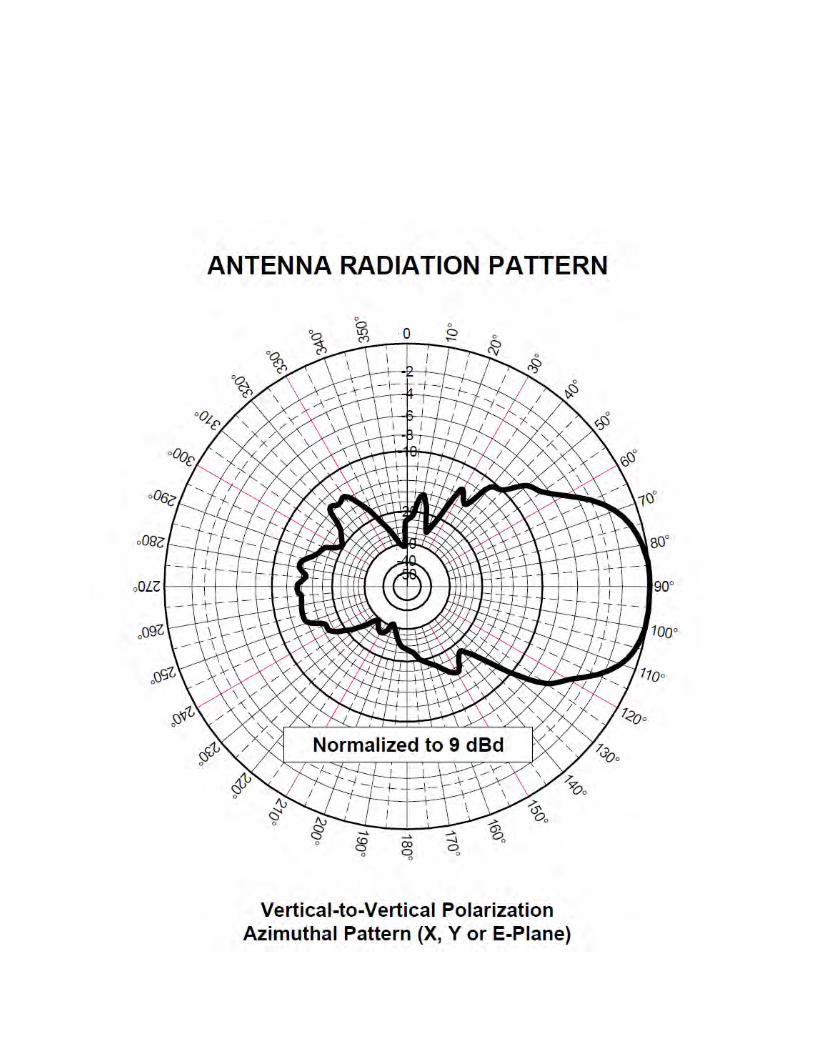
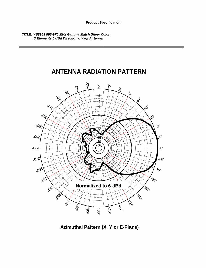
ANTENNA RADIATION PATTERN
Azimuthal Pattern (X, Y or E-Plane)
0
80°
70°
60°
50°
40°
30° 2
0° 10° 350
°
340
°
330°
320°
310°
300°
290°
280°
270°
260°
250°
240° 230°
220° 210° 200°
190°
180°
170°
160°
150° 140°
130°
120°
110°
100°
90°
-2-4-6-8-10
-20
-30-40-50
Normalized to 6 dBd

Product Specification
TITLE: YS8963 896-970 MHz Gamma Match Silver Color
3 Elements 6 dBd Directional Yagi Antenna
ANTENNA RADIATION PATTERN
Elevation Pattern (Y, Z or H-Plane)
0
80°
70°
60°
50°
40°
30° 2
0° 10° 350
°
340
°
330°
320°
310°
300°
290°
280°
270°
260°
250°
240° 230°
220° 210° 200°
190°
180°
170°
160°
150° 140°
130°
120°
110°
100°
90°
-2-4-6-8-10
-20
-30-40-50
Normalized to 6 dBd