rfe-1-bru-eip-ido-001-rev0 ts ups.pdf
TRANSCRIPT

PLANTA DE RESERVA FRÍA DE GENERACIÓN DE ETEN S.A
PROYECTO PROJECT
RESERVA FRÍA ETEN CONTRATISTA CONTRACTOR
TÍTULO TITLE
UNINTERRUPTIBLE POWER SUPPLY SYSTEMS TECHNICAL SPECIFICATION
Nº DE DOCUMENTO PROYECTO PROJECT DOCUMENT Nº
RFE-1-BRU-EIP-IDO-001
REV 0 EDITADO PARA ISSUED FOR
For Purchase FECHA DATE
04/04/2014
XGR
PRV
JSA
REALIZADO DONE BY
REVISADO CHECKED BY
APROBADO APPROVED BY
ESTE DOCUMENTO CONTIENE INFORMACIÓN PROPIETARIA Y NO PUEDE SER DUPLICADO, PROCESADO O CEDIDO A TERCEROS PARA UN USO DISTINTO AL DE ESTE PROYECTO Y EL OBJETO PARA EL QUE HA SIDO PREVISTO SIN LA AUTORIZACIÓN ESCRITA DE COBRA.
THIS DOCUMENT CONTAINS PROPIETARY INFORMATION AND CAN NOT BE DUPLICATED, PROCESSED OR DISCLOSED TO THIRD PARTIES FOR ANY USE OTHER THAN THIS PROJECT AND THE PURPOSE FOR WHICH IT IS INTENDED FOR WITHOUT THE WRITTEN CONSENT OF COBRA.

UPS SYSTEMS TECHNICAL SPECIFICATION Rev 0
RFE-1-BRU-EIP-IDO-001 Pág/Page 2 de/of 36
Este documento contiene información propiedad de Cobra y está sujeto a las restricciones detalladas en la página de portada.
La única copia controlada de este documento es la incluida en la intranet de Cobra.
This document contains proprietary information of Cobra and is subject to the restrictions set forth on the title page.
The only controlled copy of the document is located on the Cobra intranet.
CONTROL DE MODIFICACIONES/CHANGE LOG
Revisión
Revision
Fecha
Date
Modificaciones
Modifications
A 13/12/2013
FIRST EDITION
B 15/01/2014 COBRA COMMENTS
0 04/04/2014 AS PURCHASED
UPS SYSTEMS TECHNICAL SPECIFICATION Rev 0
RFE-1-BRU-EIP-IDO-001 Pág/Page 3 de/of 36
Este documento contiene información propiedad de Cobra y está sujeto a las restricciones detalladas en la página de portada.
La única copia controlada de este documento es la incluida en la intranet de Cobra.
This document contains proprietary information of Cobra and is subject to the restrictions set forth on the title page.
The only controlled copy of the document is located on the Cobra intranet.
ÍNDICE
1. OBJECT .............................................................................................................................. 5
2. REFERENCE DOCUMENTATION ...................................................................................... 6
3. GENERAL INFORMATION ................................................................................................. 7
3.1. SITE ........................................................................................................................... 7
3.1.1. Climate conditions .................................................................................... 7
3.1.2. Seismic activity ......................................................................................... 7
3.2. MATERIALS, EQUIPMENT AND COMPONENTS IDENTIFICATION ........................ 8
3.3. DOCUMENTS, DRAWINGS AND CORRESPONDENCE IDENTIFICATION ............. 8
3.4. DOCUMENTATION MANAGEMENT ......................................................................... 8
3.5. DEFINITIONS ............................................................................................................. 8
4. SCOPE OF SUPPLY AND SERVICES ............................................................................... 9
4.1. GENERAL .................................................................................................................. 9
4.1.1. Electrical main equipment ........................................................................ 9
4.1.2. Accessories and Parts ............................................................................ 11
4.2. SERVICES ............................................................................................................... 12
4.3. EQUIPMENT AND SERVICES SUPPLIED BY OTHERS ......................................... 13
4.4. LIMITS OF SUPPLY ................................................................................................. 13
5. REGULATIONS, LEGISLATION AND APPLICABLE REGULATIONS ............................ 14
6. DESIGN AND MANUFACTURING REQUIREMENTS ...................................................... 16
6.1. GENERAL ................................................................................................................ 16
6.2. MAIN CHARACTERISTICS ...................................................................................... 17
6.2.1. System output configuration ................................................................... 17
6.2.2. Rated input and output voltages ............................................................. 17
6.2.3. Battery (Control Room UPS) .................................................................. 18
6.2.4. Rectifier rated output power (Control Room UPS) .................................. 18
6.2.5. Efficiency ................................................................................................ 18
6.2.6. Noise ...................................................................................................... 19
6.2.7. Environmental conditions ....................................................................... 19
6.2.8. Degree of protection ............................................................................... 19
6.2.9. Overload ................................................................................................ 19
6.2.10. UPS distribution board short-circuit ........................................................ 19
6.3. INVERTER ............................................................................................................... 20
6.4. ELECTRONIC TRANSFER SWITCH (ETS) ............................................................. 20

UPS SYSTEMS TECHNICAL SPECIFICATION Rev 0
RFE-1-BRU-EIP-IDO-001 Pág/Page 4 de/of 36
Este documento contiene información propiedad de Cobra y está sujeto a las restricciones detalladas en la página de portada.
La única copia controlada de este documento es la incluida en la intranet de Cobra.
This document contains proprietary information of Cobra and is subject to the restrictions set forth on the title page.
The only controlled copy of the document is located on the Cobra intranet.
6.5. BYPASS TRANSFORMER ....................................................................................... 20
6.6. CABINETS ............................................................................................................... 20
6.6.1. Cooling ................................................................................................... 21
6.6.2. Protection devices .................................................................................. 21
6.6.3. Metering equipment and indicators ......................................................... 22
6.6.4. Mimic Diagram ....................................................................................... 23
6.7. AUXILIARY EQUIPMENT ......................................................................................... 23
6.7.1. Heating elements and ventilation ............................................................ 23
6.7.2. Internal Lighting and power socket ......................................................... 23
6.7.3. Internal Wiring ........................................................................................ 23
6.7.4. Terminals Blocks .................................................................................... 24
6.7.5. Finishing and surface coating ................................................................. 25
6.7.6. Labels .................................................................................................... 25
6.7.7. Nameplate .............................................................................................. 25
6.8. SIGNALLING ............................................................................................................ 27
7. QUALITY CONTROL ........................................................................................................ 28
8. TESTING AND INSPECTION ............................................................................................ 29
8.1. GENERAL TESTS .................................................................................................... 29
8.2. TYPE TESTS ........................................................................................................... 29
8.3. ROUTINE TESTS ..................................................................................................... 29
8.4. ON SITE INSPECTIONS .......................................................................................... 30
9. GUARANTEES ASSOCIATED WITH THE SUPPLY ........................................................ 31
10. DOCUMENTATION FOR SUBMISSION ........................................................................... 32
11. ANNEXES ......................................................................................................................... 35

UPS SYSTEMS TECHNICAL SPECIFICATION Rev 0
RFE-1-BRU-EIP-IDO-001 Pág/Page 5 de/of 36
Este documento contiene información propiedad de Cobra y está sujeto a las restricciones detalladas en la página de portada.
La única copia controlada de este documento es la incluida en la intranet de Cobra.
This document contains proprietary information of Cobra and is subject to the restrictions set forth on the title page.
The only controlled copy of the document is located on the Cobra intranet.
1. OBJECT
The object of this technical specification is to cover the design, manufacturing, testing and
inspection, cleaning, packaging, pre-commissioning and commissioning supervision, testing at
site and guarantees of the Uninterruptible Power Supply for the ETÉN Power Generation Plant
(Peru), which has an approximate power of 230 MW.
There are two different UPS systems:
• A dual UPS inverter an Distribution Board for the Plant control systems
• A single UPS complete system for the Control Room.

UPS SYSTEMS TECHNICAL SPECIFICATION Rev 0
RFE-1-BRU-EIP-IDO-001 Pág/Page 6 de/of 36
Este documento contiene información propiedad de Cobra y está sujeto a las restricciones detalladas en la página de portada.
La única copia controlada de este documento es la incluida en la intranet de Cobra.
This document contains proprietary information of Cobra and is subject to the restrictions set forth on the title page.
The only controlled copy of the document is located on the Cobra intranet.
2. REFERENCE DOCUMENTATION
The following documentation shall be used as a reference in this specification:
Specific reference documents:
� RFE-1-BRU-EHP-IDO-001 “UPS System Data Sheet” � RFE-1-BTA-ECE-IDO-001 “DC batteries and distribution boards Calculation” � RFE-1-UBE-EMI-IDO-001 “E.T. Edificios modulares prefabricados para las
instalaciones eléctricas � RFE-1-YE_-ERD-IDO-001 “Electric Design Criteria” � RFE-1-YTG-GDA-IDO-002 “General layout” � RFE-1-YF_-GI_-IDO-001 ”General Painting and Coating Specification” � RFE-1-BTA-EIP-IDO-001 “DC System Technical Specification”
Generic reference documents:
� RFE-1-YDC-G__-IDO-001 “KKS system application” � RFE-1-DIR-PRO-CPI-003 "Co-ordination procedure" � RFE-1-DIR-PRO-CPI-002 "Coding procedure" � RFE-1-COM-PRO-CPI-007 “Seller Quality Assurance”

UPS SYSTEMS TECHNICAL SPECIFICATION Rev 0
RFE-1-BRU-EIP-IDO-001 Pág/Page 7 de/of 36
Este documento contiene información propiedad de Cobra y está sujeto a las restricciones detalladas en la página de portada.
La única copia controlada de este documento es la incluida en la intranet de Cobra.
This document contains proprietary information of Cobra and is subject to the restrictions set forth on the title page.
The only controlled copy of the document is located on the Cobra intranet.
3. GENERAL INFORMATION
3.1. SITE
The plant shall be located a few kilometres from the municipal district of Reque in the province of
Chiclayo in the department of Lambayeque – Peru.
3.1.1. Climate conditions
The following climate conditions are adopted for the design:
� Mean temperature ............................................................................................ 21.7 ºC � Ambient temperature range .............................................................. 14.6 ºC – 33.9 ºC � Relative humidity ............................................................................................... 73.2 % � Relative humidity range ...................................................................... 64.9 % - 81.0 % � Atmospheric pressure .............................................................................. 1013.9 mbar � Elevation .................................................................................................. +77.5 m asl � Location ..................................................................... Near to the sea (approx. 10 Km) � Maximum wind speed ..................................................................................... 95 km/h � Prevailing wind direction ................................................................... 179.3º from SSE � Average annual rainfall ................................................................................. 77.5 mm � Average monthly rainfall with “El Niño” phenomenon ..................................... 173 mm � Desert environment: Dirty Ambient .................................................................. 50µg/m3
3.1.2. Seismic activity
According to regulation “E.030 Diseño Sismorresistente”, the seismic features to apply on the
calculations will be the following:
• Soil profile type S1:
• Lambayeque Department: seismic area 3:
• Maximum horizontal ground acceleration (10 % probability of been exceed in 50 years): 0.40g where “g” is the gravity acceleration.
• Tp: period that defines the spectrum platform : 0.4 s
• S (soil factor): 1.0
This section does not discard the application of the document "RFE-1-YC_-CRD-IDO-006 criteria
of design of work Civil and structures". Therefore the equipment must be anchored so that to

UPS SYSTEMS TECHNICAL SPECIFICATION Rev 0
RFE-1-BRU-EIP-IDO-001 Pág/Page 8 de/of 36
Este documento contiene información propiedad de Cobra y está sujeto a las restricciones detalladas en la página de portada.
La única copia controlada de este documento es la incluida en la intranet de Cobra.
This document contains proprietary information of Cobra and is subject to the restrictions set forth on the title page.
The only controlled copy of the document is located on the Cobra intranet.
avoid the effects of the earthquake to cause movement or displacement that pose a danger to
people and other structures and equipment.
3.2. MATERIALS, EQUIPMENT AND COMPONENTS IDENTIFICATION
Identification of materials, equipment and components shall be according to document RFE-1-
YDC-G__-IDO-001 “KKS system application”.
3.3. DOCUMENTS, DRAWINGS AND CORRESPONDENCE IDENTIFICATION
Coding of all the documents, drawings and correspondence related to the project shall be
performed according to the criteria indicated in documents RFE-1-DIR-PRO-CPI-002 "Coding
procedure" and RFE-1-DIR-PRO-CPI-007 "Procedure to assure seller quality and documentation
management".
3.4. DOCUMENTATION MANAGEMENT
Management of the documentation shall be according to the indications recorded in the
document RFE-1-DIR-PRO-CPI-003 "Co-ordination procedure".
3.5. DEFINITIONS
The following definitions shall be used in this specification for the different parties involved:
OWNER: is the company that holds the project concession.
CONTRACTOR: is the company UTE RESERVA FRÍA ETEN, S.A., Main Contractor of the works, hired by the Owner.
SUBCONTRACTORS: are each one of the suppliers of equipment and/or services hired by the Contractor.

UPS SYSTEMS TECHNICAL SPECIFICATION Rev 0
RFE-1-BRU-EIP-IDO-001 Pág/Page 9 de/of 36
Este documento contiene información propiedad de Cobra y está sujeto a las restricciones detalladas en la página de portada.
La única copia controlada de este documento es la incluida en la intranet de Cobra.
This document contains proprietary information of Cobra and is subject to the restrictions set forth on the title page.
The only controlled copy of the document is located on the Cobra intranet.
4. SCOPE OF SUPPLY AND SERVICES
4.1. GENERAL
This specification covers the main design parameters, manufacture, marking, testing and
inspection, acceptance / rejection, delivery, packing, unloading, assembly and commissioning
supervision, and guarantee of two different UPS Systems.
Any discrepancy between this document and the document RFE-1-BTA-EHP-IDO-001 “DC
System Data Sheet”, and with the applicable standards to comply with the Object of this
document shall be communicated to the Purchaser.
The installations and devices used shall be low-maintenance.
All materials shall be new and top quality. They shall conform to the latest IEC or IEEE standards
and regulations. They shall easily cope with the prevailing loads and stresses at the installation
site, in particular the short circuit ratios.
All installations and their parts shall be designed so that their operation does not cause excessive
vibrations. The installations and installation parts shall also ensure that reciprocal electrical
interference with the feeding system is minimised and electromagnetic compatibility is ensured.
4.1.1. Electrical main equipment
Supply shall include the following equipment and components:
Plant UPS System
This system will be fed from the 125 VDC System, and comprises the following equipment.
• Two (2) 125 V DC / 220-127 VAC Inverter (1BRU51 and 1 BRU 52) each one for 100% of demanded power, comprising each one the 3 phase inverter, isolation transformer and electronic transfer switch (ETS), with protection, control and measure unit.
• One (1) 3 phase By-Pass Transformer (1BRT53)
• Two (2) 220/127 VAC 3 phase Distribution Boards (1BRA51 and 1BUA52) each of them fed from the corresponding rectifier-battery charger and the by-pass

UPS SYSTEMS TECHNICAL SPECIFICATION Rev 0
RFE-1-BRU-EIP-IDO-001 Pág/Page 10 de/of 36
Este documento contiene información propiedad de Cobra y está sujeto a las restricciones detalladas en la página de portada.
La única copia controlada de este documento es la incluida en la intranet de Cobra.
This document contains proprietary information of Cobra and is subject to the restrictions set forth on the title page.
The only controlled copy of the document is located on the Cobra intranet.
transformer, with a Maintenance Changeover Transfer Switch, with inverter lockout control to assure a safe “make before break” transfer.
Fig 1: UPS Plant Basic One Line Diagram
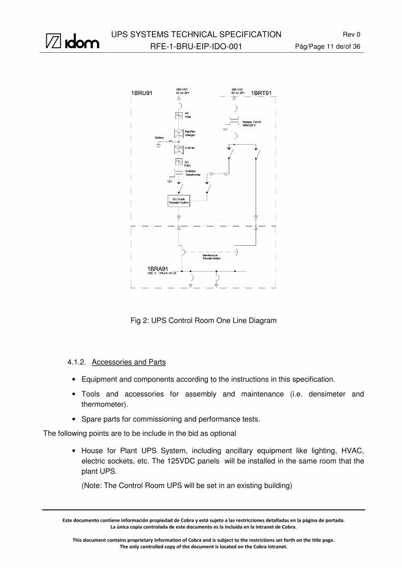
Control Room System
This will be a full commercial UPS, a by-pass transformer and a distribution panel board. The
main equipment is:
• One UPS (1BRU91) that includes a 3Φ 480 V 60 Hz rectifier-battery charger, a battery, an
inverter 3Φ 220-127 V 60 Hz, and an Electronic Transfer Switch with an independent
feeder.
• One by-pass transformer 480 / 220-127 V 60 Hz (1BRT91).
• One Distribution Board (1BRA91) with a Maintenance Changeover Transfer Switch, with
inverter lockout control to assure a safe “make before break” transfer.
ElectronicTransfer Switch
220/127 V, 3Ph, 60 Hz1BRA52
3Ph Inverter
220/127 V, 3Ph, 60 Hz1BRA51
Bypass Transf..480/220 V
1BRT531BRU52 1BRU51
125 VDC1BUA52
125 VDC1BUA51
480 VAC60 Hz 3Ph
ACFilter
IsolationTransformer
ACFilter
IsolationTransformer
ElectronicTransfer Switch
MaintenanceTransfer-Switch
MaintenanceTransfer-Switch
3Ph Inverter
UPS SYSTEMS TECHNICAL SPECIFICATION Rev 0
RFE-1-BRU-EIP-IDO-001 Pág/Page 11 de/of 36
Este documento contiene información propiedad de Cobra y está sujeto a las restricciones detalladas en la página de portada.
La única copia controlada de este documento es la incluida en la intranet de Cobra.
This document contains proprietary information of Cobra and is subject to the restrictions set forth on the title page.
The only controlled copy of the document is located on the Cobra intranet.
Fig 2: UPS Control Room One Line Diagram
4.1.2. Accessories and Parts
• Equipment and components according to the instructions in this specification.
• Tools and accessories for assembly and maintenance (i.e. densimeter and thermometer).
• Spare parts for commissioning and performance tests.
The following points are to be include in the bid as optional
• House for Plant UPS System, including ancillary equipment like lighting, HVAC, electric sockets, etc. The 125VDC panels will be installed in the same room that the plant UPS.
(Note: The Control Room UPS will be set in an existing building)
UPS SYSTEMS TECHNICAL SPECIFICATION Rev 0
RFE-1-BRU-EIP-IDO-001 Pág/Page 12 de/of 36
Este documento contiene información propiedad de Cobra y está sujeto a las restricciones detalladas en la página de portada.
La única copia controlada de este documento es la incluida en la intranet de Cobra.
This document contains proprietary information of Cobra and is subject to the restrictions set forth on the title page.
The only controlled copy of the document is located on the Cobra intranet.
4.2. SERVICES
The specification also covers the following services for each and any item:
• Design of the equipment.
• Stocking materials, manufacturing, supply and storage.
• Inspections and testing at the Subcontractor's workshop, or those of its subcontractors.
• Identification.
• Surface preparation and coating.
• Packaging, marking, insurance and transport to the Plant. Unloading to be performed by others.
• Extra Paint and Coating for small repairs and retouches.
• Supervision of the assembly.
• Operating tests.
• Attendance and supervision during the start-up and commissioning at the requirement of the Contractor.
• Supply of any tool and special equipment that may be necessary for assembly, maintenance or operation of the equipment.
• Supply of spare parts for tests and commissioning.
• List of spare parts for operation, for two (2) years of operation that will be offered as an option. The parts chosen shall be delivered in a properly identified and independent box with its materials list.
• Documentation required to be detailed in this requisition: general layout drawings, section drawings, electric schemes, quality dossier, operating and maintenance manuals, etc.
• Guarantees.
• The Supplier shall include in the offer the documents list that will need during the engineering stage of the supply.
• Relays and controllers setup.
UPS SYSTEMS TECHNICAL SPECIFICATION Rev 0
RFE-1-BRU-EIP-IDO-001 Pág/Page 13 de/of 36
Este documento contiene información propiedad de Cobra y está sujeto a las restricciones detalladas en la página de portada.
La única copia controlada de este documento es la incluida en la intranet de Cobra.
This document contains proprietary information of Cobra and is subject to the restrictions set forth on the title page.
The only controlled copy of the document is located on the Cobra intranet.
4.3. EQUIPMENT AND SERVICES SUPPLIED BY OTHERS
The following equipment, materials and services will be supplied by others and are not included
in the scope of supply.
• Erection and commissioning.
• Foundations and anchors.
• External wiring.
• Those pointed out in the e-house specification.
4.4. LIMITS OF SUPPLY
The following limits of supply are established:
• Input and output terminals of the external power cables to the UPS and Panel Boards.
• Grounding terminals of UPS Boards or e-Houses.
• Input and output terminals of the external signal cables to UPS System.
• If the e-house is in the scope, the terminal blocks of the panel for the lightning and sockets
• If the e-house is in the scope:
o The terminal blocks of the internal panel or an external junction box for the lightning and sockets (380/220 VAC)
o The terminal blocks of the HVAC board or an external junction box (480 VAC)
• NOTE: If the Plant UPS System and the Plant DC System are supplied by the same Sub-contractor, they shall be placed in the same e-House and the interconnection cables between DC and Inverter must be included in the offer.

UPS SYSTEMS TECHNICAL SPECIFICATION Rev 0
RFE-1-BRU-EIP-IDO-001 Pág/Page 14 de/of 36
Este documento contiene información propiedad de Cobra y está sujeto a las restricciones detalladas en la página de portada.
La única copia controlada de este documento es la incluida en la intranet de Cobra.
This document contains proprietary information of Cobra and is subject to the restrictions set forth on the title page.
The only controlled copy of the document is located on the Cobra intranet.
5. REGULATIONS, LEGISLATION AND APPLICABLE REGULATIONS
The equipment shall be according to the latest applicable legislation and regulations in Peru,
whether national, regional or local.
In the event of discrepancy between the standards cited, or between them and this specification,
the most restrictive one shall be applied. Notwithstanding this, the Subcontractor must notify the
Contractor in writing of any conflict that exists, in order to provide a final interpretation.
Moreover, they shall bear the applicable codes, regulations and legislations, and in particular the
last reviews of the following standards:
o CNE : “Código Nacional de Electricidad: Utilización”. Especially chapter 150 (Electrical equipment, that includes transformers, panels and batteries)
o NTP : Normas Técnicas Peruanas.
o IEC 62040-1: Uninterruptible power systems (UPS) – Part 1: General and safety requirements for UPS
o IEC 62040-2: Uninterruptible power systems (UPS) - Part 3: Method of specifying the performance and test requirements
o IEC 60146-1-1: Semiconductor converters - General requirements and line commutated converters - Part 1-1: Specification of basic requirements
o IEC 60146-1-3: Semiconductor convertors - General requirements and line commutated convertors - Part 1-3: Transformers and reactors
o IEC 61439 Low-voltage switchgear and controlgear assemblies
o IEC 60947: Standards for low voltage switchgear and controlgear.
o IEC 61000-6-2 Electromagnetic compatibility (EMC) - Part 6-2: Generic standards - Immunity for industrial environments
o IEC 61000-6-4 Electromagnetic compatibility (EMC) - Part 6-4: Generic standards - Emission standard for industrial environments
o IEC 60950–1 Information technology equipment – Safety
o IEC specific for electric and electronic devices.
o EN 50272 “Safety requirements for secondary batteries and battery installations. General safety information”
o IEC 60364 -4- 41 Low-voltage electrical installations - Part 4-41: Protection for safety - Protection against electric shock

UPS SYSTEMS TECHNICAL SPECIFICATION Rev 0
RFE-1-BRU-EIP-IDO-001 Pág/Page 15 de/of 36
Este documento contiene información propiedad de Cobra y está sujeto a las restricciones detalladas en la página de portada.
La única copia controlada de este documento es la incluida en la intranet de Cobra.
This document contains proprietary information of Cobra and is subject to the restrictions set forth on the title page.
The only controlled copy of the document is located on the Cobra intranet.
o IEC 60364 -4- 42, Electrical installations of buildings – Part 4 - 42: Protection for safety – Protection against thermal effects
o IEC 60364 -5- 54 Electrical installations of buildings – Part 5 – 52 Selection and erection of electrical equipment - Earthing arrangements and protective conductors
UPS SYSTEMS TECHNICAL SPECIFICATION Rev 0
RFE-1-BRU-EIP-IDO-001 Pág/Page 16 de/of 36
Este documento contiene información propiedad de Cobra y está sujeto a las restricciones detalladas en la página de portada.
La única copia controlada de este documento es la incluida en la intranet de Cobra.
This document contains proprietary information of Cobra and is subject to the restrictions set forth on the title page.
The only controlled copy of the document is located on the Cobra intranet.
6. DESIGN AND MANUFACTURING REQUIREMENTS
The following requirements are intended for the Plant UPS System. The Control Room UPS
should be simplified.
6.1. GENERAL
The Uninterruptible Power Supply (UPS) System will consist of two independent sets of inverters
plus an Electronic Transfer Switch. Each UPS will be supplied from one of the half-busbars of the
125 Vdc Distribution Boards and from the By-Pass Transformer.
The Uninterruptible LV Distribution Boards will feed in alternating current all critical loads at 220-
127 Vac.
The critical loads in the power plant are fed from the two UPS, and, individually, this loads
switches from one to the other in case of failure.
In case of failure of one of the inverters, the load from this inverter will be fed from the bypass
transformer, through the Electronic Transfer Switch (ETS).
In case of maintenance, the Maintenance Changeover Transfer Switch will be closed to the by-
pass position. To assure a safe “make before break” transfer, the inverter shall lock up the
transfer switch till the frequency and voltage of the two sources are synchronized.
The Uninterruptible Power System (UPS) and the auxiliary equipment will be installed within an e-
House, whose supply is optional in the bid.
Uninterruptible Power Supply (UPS) System shall be completed with all accessories and
necessary auxiliary equipment.
The terminal arrangement and connections shall not restrict access to maintenance and
inspection.
The Supplier shall include in his offer dimensional drawings of UPS, boards, and auxiliary
equipment with dimensions of equipment, minimum clearance distances, etc.
UPS system shall be sized to feed the plant critical loads related to:
• DCS.

UPS SYSTEMS TECHNICAL SPECIFICATION Rev 0
RFE-1-BRU-EIP-IDO-001 Pág/Page 17 de/of 36
Este documento contiene información propiedad de Cobra y está sujeto a las restricciones detalladas en la página de portada.
La única copia controlada de este documento es la incluida en la intranet de Cobra.
This document contains proprietary information of Cobra and is subject to the restrictions set forth on the title page.
The only controlled copy of the document is located on the Cobra intranet.
• Turbine/generator control panel.
• Skid PLC.
• Work station computers.
• Communications/telemetry.
6.2. MAIN CHARACTERISTICS
6.2.1. System output configuration
The 220-127 VAC, 60 Hz, 3 phases plus neutral, shall be configured as a TN system according to
IEC 60364 -4- 41.
Protective conductor system shall be according to Peruvian regulation and to IEC 60364 -5- 54
6.2.2. Rated input and output voltages
The waveform of the output voltage shall be sinusoidal, with the total allowable distortion of the
wave with a linear load less than 5% (RMS), and the distortion of any harmonic less than 3%.
Plant UPS
The input voltage range for the inverters, from the DC System, is 125 VDC +10% -15%
The input voltage range for the by-pass transformer is 480 VAC ±10%.
The frequency input range of the by-pass transformer is 60 Hz with a tolerance less than ±0.5%.
The rated output voltage of the UPS system must be 3Φ+N 220-127 Vac, adjustable manually
within a ±5% margins.
Steady voltage admissible variation less than ±1%, and dynamic response to sudden load less
than ±2% with a recovery time 4 ms.
Inverter shall synchronize within 220 VAC ±10% and 60 Hz ±5%.

UPS SYSTEMS TECHNICAL SPECIFICATION Rev 0
RFE-1-BRU-EIP-IDO-001 Pág/Page 18 de/of 36
Este documento contiene información propiedad de Cobra y está sujeto a las restricciones detalladas en la página de portada.
La única copia controlada de este documento es la incluida en la intranet de Cobra.
This document contains proprietary information of Cobra and is subject to the restrictions set forth on the title page.
The only controlled copy of the document is located on the Cobra intranet.
Control Room UPS
The input voltage range for the inverters, from the Essential LV System, is 480 VAC ±10%.
The input voltage range for the by-pass transformer is 480 VAC ±10%.
The frequency input range of the by-pass transformer is 60 ±5 Hz.
The rated output voltage of the UPS system must be 1Φ+N 220 Vac, manually adjustable within
a ±5% margins.
Steady voltage admissible variation less than ±1%, and dynamic response to sudden load less
than ±2% with a recovery time 4 ms.
Inverter shall synchronize within 220 VAC ±10% and 60 Hz ±5%.
6.2.3. Battery (Control Room UPS)
The Control Room UPS System includes the battery.
The necessary range in the case of network failure shall be 30 minutes.
The mean life for the battery shall be greater than 10 years at room conditions (with HVAC and
25ºC).
The time available to recharge the batteries must be less than twelve (10) hours (till 80%
batteries capacity).
6.2.4. Rectifier rated output power (Control Room UPS)
The output rated power of the battery charger rectifier is determined taking into account that the
battery charger rectifier will supply the total rated power required of the direct current of the plant.
The Supplier shall calculate the required power in accordance with the Battery Discharge Cycle,
and with loads and reserve loads indicated in this specification.
6.2.5. Efficiency
The efficiency of the equipment shall not be less than 85% at rated load.

UPS SYSTEMS TECHNICAL SPECIFICATION Rev 0
RFE-1-BRU-EIP-IDO-001 Pág/Page 19 de/of 36
Este documento contiene información propiedad de Cobra y está sujeto a las restricciones detalladas en la página de portada.
La única copia controlada de este documento es la incluida en la intranet de Cobra.
This document contains proprietary information of Cobra and is subject to the restrictions set forth on the title page.
The only controlled copy of the document is located on the Cobra intranet.
6.2.6. Noise
Noise level at 1 m distance shall not exceed 75 dB for the Plant UPS, and 65 dB for the Control
Room UPS, when the system will be operating at full load. Fans should be of low noise level.
6.2.7. Environmental conditions
The UPS Systems shall be suitable for correct indoor operation temperature of 40 ºC.
6.2.8. Degree of protection
The UPS Boards shall have at least a degree of protection IP 21 in accordance with IEC 60529.
6.2.9. Overload
The inverters have to withstand an overload of at least:
� 25% for 10 minutes � 50% for 1 minute. � Maximum output short circuit 3xIrate
6.2.10. UPS distribution board short-circuit
The Uninterruptible LV Distribution Boards shall have the following electrical characteristics:
� Short circuit current (1sec.) for main busbar: ...................................................... 10 kA � Peak short circuit current: ..................................................................................... 25 kA
This characteristic shall be considered as a reference, but the sub-contractor shall take into
account the short circuit current contribution of inverters and by-pass transformer considering the
worst case.
Subcontractor has to carry out a Protection Coordination scheme between main Circuit Breakers
and the output feeders breakers. If not otherwise determined main circuit breakers shall have
thermal regulation 0,7-1xIn and magnetic trip shall fulfil 1-10xIn regulation.
The short circuit withstand of DC and AC Distribution System shall be confirmed by the
Contractor during the construction stage.
UPS SYSTEMS TECHNICAL SPECIFICATION Rev 0
RFE-1-BRU-EIP-IDO-001 Pág/Page 20 de/of 36
Este documento contiene información propiedad de Cobra y está sujeto a las restricciones detalladas en la página de portada.
La única copia controlada de este documento es la incluida en la intranet de Cobra.
This document contains proprietary information of Cobra and is subject to the restrictions set forth on the title page.
The only controlled copy of the document is located on the Cobra intranet.
6.3. INVERTER
Each inverter shall be a high frequency IGBT bridge with a current-limiting system in case of
overloads or short circuits.
Each inverter must be protected against overvoltages, overloads and short circuits. In the
incoming of each inverter, a circuit breaker will be installed, equipped with a current-limiting diode
in case of reverse polarity.
The inverter should be equipped with network synchronisation device and a lockout system to
allow transfers without interrupting the supply of power to connected loads..
The inverter shall maintain the specified voltage and frequency, based on an internal reference
despite the input conditions.
6.4. ELECTRONIC TRANSFER SWITCH (ETS)
The electronic transfer switch (ETS) which switches the loads to the by-pass system without
interruption in the event of an internal fault or overload is required to increase the availability of
the UPS unit.
6.5. BYPASS TRANSFORMER
To provide electrical isolation between the normal services and AC critical loads, as well as to
adapt the input voltage level to the output level, there will be a bypass transformer with solid
grounding, which also will be used to perform a manual bypass, so that the Uninterruptible LV
Distribution Boards can be fed directly from the LV Main Distribution Board.
6.6. CABINETS
Each inverter plus ETS or the complete UPS set must be provided in a self-supporting panel or a
wall-mounted panel type depending on the size of the equipment. Each cabinet shall be designed
to withstand all mechanical stress without causing loss of electrical insulation.
The distribution board shall include all necessary switches, busbars and circuit breakers.

UPS SYSTEMS TECHNICAL SPECIFICATION Rev 0
RFE-1-BRU-EIP-IDO-001 Pág/Page 21 de/of 36
Este documento contiene información propiedad de Cobra y está sujeto a las restricciones detalladas en la página de portada.
La única copia controlada de este documento es la incluida en la intranet de Cobra.
This document contains proprietary information of Cobra and is subject to the restrictions set forth on the title page.
The only controlled copy of the document is located on the Cobra intranet.
Suitable interlocks shall be provided to achieve the configuration as shown in the diagrams.
Panels will be metallic and made of bended and welded flat steel plate with a thickness of at least
1,2 mm. IK08 protection is required. Doors will have 2 mm thickness and IK08 protection.
All the modules shall be of fixed type.
Cable runs shall be provided with separate access. It shall be possible to safely carry out
maintenance work on cable connections to any one circuit when the adjacent circuits are live.
Suitable identification shall be given to all the internal components as well as to those on the front
of the panel. For the external connections the identification shall be accordance with the KKS
system of the plant.
The boards shall be supplied completely hardwired, assembled and routine tested.
Cable entry shall be from bottom-side.
Control switches and devices shall be incorporated only in the front of the panels. No operated
device shall be located less than 250 mm above ground level.
All the incoming and outgoing circuits shall be circuit breaker protected.
The on, off and trip position of the circuit breakers shall be clearly indicated and visible to the
operator when mounted in service.
The busbars shall consist of high conductivity copper. The polarity of the busbars shall be marked
with letters and colours.
In the lower part of the vertical sections, there shall be an earthing busbar to which all of the non-
live metal parts of the panel shall be connected.
6.6.1. Cooling
UPS System Boards shall be cooled by natural circulation preferably.
6.6.2. Protection devices
Each rectifier-battery charger shall incorporate the following protections:
• Inverter DC input overcurrent: Isolator switch.

UPS SYSTEMS TECHNICAL SPECIFICATION Rev 0
RFE-1-BRU-EIP-IDO-001 Pág/Page 22 de/of 36
Este documento contiene información propiedad de Cobra y está sujeto a las restricciones detalladas en la página de portada.
La única copia controlada de este documento es la incluida en la intranet de Cobra.
This document contains proprietary information of Cobra and is subject to the restrictions set forth on the title page.
The only controlled copy of the document is located on the Cobra intranet.
• UPS and bypass transformer AC input. One (1) 3 phase circuit breaker.
• Inverter overload: Electronic current-limiter.
• Inverter output overvoltage: Varistors (preferably) or dischargers.
• Reverse current (DC bus): Diodes.
• Measurement and control circuits: Fuses
6.6.3. Metering equipment and indicators
The measurement equipment shall be mounted visibly on the front of Boards without opening the
panel. The position and mounting of all equipment will be such that it allows easy and safe
access to the terminals.
These measurement and indicators could be integrated in a graphical display, but providing a
minimum number of status and alarm lamps for the main faults
The signal lamps shall be high-luminance led. The use of incandescent or neon lamps is not
acceptable.
The measurement equipment and signaling would include the following:
• DC and AC input voltages (U).
• Input currents (I).
• Three-phase output voltages (U).
• Three-phase output currents (I).
• Status ( Inverter On, By-pass On, AC and DC inputs loss or out of range)
• Fault alarms (Fuses and breaker trips, bridge fault, etc)
• Minor alarms
Additionally for the Control Room UPS:
• Battery charging / discharging current.
• Battery Voltage.
• Battery Status (float, charging, discharging)

UPS SYSTEMS TECHNICAL SPECIFICATION Rev 0
RFE-1-BRU-EIP-IDO-001 Pág/Page 23 de/of 36
Este documento contiene información propiedad de Cobra y está sujeto a las restricciones detalladas en la página de portada.
La única copia controlada de este documento es la incluida en la intranet de Cobra.
This document contains proprietary information of Cobra and is subject to the restrictions set forth on the title page.
The only controlled copy of the document is located on the Cobra intranet.
• Battery fault conditions.
• Rectifier/charger fault alarms.
6.6.4. Mimic Diagram
A frontal mimic diagram shall be included in the UPS and the distribution panel board. The mimic
diagram shall document all possible operating modes.
6.7. AUXILIARY EQUIPMENT
6.7.1. Heating elements and ventilation
Thermostat or humidistat -controlled heating elements shall be installed at the bottom of each
panel. These elements shall be easy to access and remove.
Adequate ventilation (natural or forced) shall be installed to prevent exceeding the acceptable
temperature limits and to always guarantee the degree of ambient protection for the UPS.
Both elements of the Plant UPS shall be fed from an external source 220 V 60 Hz 1phase +
neutral, supplied from the Contractor. For the Control Room UPS these elements shall be feed
from internal sources.
6.7.2. Internal Lighting and power socket
Each panel will be provided with lighting, powered by the switch to open the door, and a power
socket for 10 A and 220 VAC 1Ph+N+PE (“Schucko” type)
The lighting and power socket system must be protected by fuses. The replacement of the lamp
must be done without interfering with other circuits.
Those circuits shall be fed from the same supply than the heaters.
6.7.3. Internal Wiring
All wires will comply with non-flame and non-fire propagating test as per IEC 60332. All wires
must be resistant to the ambient conditions of the installation.

UPS SYSTEMS TECHNICAL SPECIFICATION Rev 0
RFE-1-BRU-EIP-IDO-001 Pág/Page 24 de/of 36
Este documento contiene información propiedad de Cobra y está sujeto a las restricciones detalladas en la página de portada.
La única copia controlada de este documento es la incluida en la intranet de Cobra.
This document contains proprietary information of Cobra and is subject to the restrictions set forth on the title page.
The only controlled copy of the document is located on the Cobra intranet.
All wiring shall be run in PVC open slotted cable trunking complete with fitted snap on lid or inside
flexible conduits. For small lengths of wiring that are not running in PVC trunking or conduits shall
be neatly supported with nylon cable ties at spacing no greater than 100 mm.
Wiring between panel(s) and hinged doors shall be of sufficient length to enable the door to swing
fully open. Provide flexible mechanical protection around each wiring bunch (i.e. plastic tubes)
and anchor both ends.
All wires shall be number ferruled at each end and shall NOT be joined or teed between
terminals. Wire ferrule numbers/letters shall match those shown in the Connection Diagrams.
Connections and wiring shall be arranged with special care to prevent overheating from bunched
conductors and to give a tidy appearance.
All the control wires are shielded with copper braid.
All wires will be carried to terminal blocks clearly marked, where the external connections will be
done. Cable entries shall be through the bottom of the panels.
The wires used must have at least the following cross sections:
• Power circuits > 1,5 mm2.
• Control circuits > 0,6 mm2.
6.7.4. Terminals Blocks
Terminals Block shall be rail mounted, insulated and with screw clamp connection type. They
shall be manufactured from self-extinguishing plastic material.
External block terminals must be prepared for cable sections with an extra sizing factor of 150%.
Final power cable data will be detailed in engineer stage. For power circuits shall have a current
rating of not less than 20 A with smallest terminals being capable of taking stranded conductors
up to 2,5 mm2.
The maximum number of wires to be connected on each side of a terminal shall be one. If
necessary, provide additional terminals to meet this requirement with manufacturer’s standard
internal jumper bars.

UPS SYSTEMS TECHNICAL SPECIFICATION Rev 0
RFE-1-BRU-EIP-IDO-001 Pág/Page 25 de/of 36
Este documento contiene información propiedad de Cobra y está sujeto a las restricciones detalladas en la página de portada.
La única copia controlada de este documento es la incluida en la intranet de Cobra.
This document contains proprietary information of Cobra and is subject to the restrictions set forth on the title page.
The only controlled copy of the document is located on the Cobra intranet.
Earth terminals shall be green or green/yellow. Other terminals shall not be the same colour as
earth terminals.
Strip terminals type shall not be used.
They shall be labeled using the terminal Manufacturer’s labeling system. “Stick on” adhesive type
terminal markers are NOT acceptable. Terminals numbers shall match those shown on the
Connection diagrams.
6.7.5. Finishing and surface coating
Painting and coating requirements are included in document RFE-1-YF_-GI_-IDO-001. Coating
and painting procedures must be approved by the Contractor. Paint for repairing minor scratches
will also be included in the offer.
According to this document the preferred colour for panels is RAL 1015 “Light Beige”.
6.7.6. Labels
All equipment shall be uniquely identified with engraved labels. The lettering shall be upper case,
black, except for danger and warning labels, where it shall be red. The background of all labels
shall be white. Labels of the embossed or transfer types shall not be used.
The labels shall be permanently fixed with not less than two corrosion proof, dust tight fixings,
prominently positioned generally over the equipment which they identify. The method of fixing
shall be submitted for approval by the Contractor.
The Sub-Contractor shall provide the Contractor with a list of all proposed labels for approval
prior to engraving. Labels shall be in Spanish language.
Boards shall have a warning plate for electrical hazards.
6.7.7. Nameplate
The Sub-contractor will provide a nameplate at an easily accessible place of the Equipment.
Nameplate shall be white laminate plastic, constructed on corrosion proof material, and painted
with weather-proof, oil proof and UV proof painting.

UPS SYSTEMS TECHNICAL SPECIFICATION Rev 0
RFE-1-BRU-EIP-IDO-001 Pág/Page 26 de/of 36
Este documento contiene información propiedad de Cobra y está sujeto a las restricciones detalladas en la página de portada.
La única copia controlada de este documento es la incluida en la intranet de Cobra.
This document contains proprietary information of Cobra and is subject to the restrictions set forth on the title page.
The only controlled copy of the document is located on the Cobra intranet.
All data stamped on the nameplate must be in Spanish language, and units shall be according to
International System of Units (S.I.).
Nameplate will be proposed for approval of the Contractor, and shall be in accordance with the
IEC 61439.
The equipment nameplate must include their KKS coding.
The nameplate will have the following data:
• KKS
• Manufacturer name.
• Serial number.
• Year of manufacture
• Model
• Rated input voltages
• Rated input currents
• Frequency input
• Rated output voltage
• Rated output current
• Rated power of the inverter
• Operating temperature
• Degree of protection
• Total weight
And for the Control Room UPS include
• Equipment range in hours or minutes
• Capacity, type, and composition of the battery
UPS SYSTEMS TECHNICAL SPECIFICATION Rev 0
RFE-1-BRU-EIP-IDO-001 Pág/Page 27 de/of 36
Este documento contiene información propiedad de Cobra y está sujeto a las restricciones detalladas en la página de portada.
La única copia controlada de este documento es la incluida en la intranet de Cobra.
This document contains proprietary information of Cobra and is subject to the restrictions set forth on the title page.
The only controlled copy of the document is located on the Cobra intranet.
6.8. SIGNALLING
All alarm and control signals for each UPS and distribution board shall be transmitted to the
Decentralized Control System (DCS) via Modbus TCP, except a general malfunction digital
output direct to the DCS.
The following Modbus signals list is for reference purpose only, and will be fully developed when
detailed engineering (D/Digital, A/Analog, I/Input to DCS, O/Output from DCS):
• DC and AC input voltages (A).
• Input currents (A).
• Three-phase output voltages (A).
• Three-phase output currents (A).
• Status (D): Inverter On, By-pass On, AC and DC inputs loss or out of range
• Fault alarms (D) (Fuses and breaker trips, bridge fault, etc)
• Grouped in one digital signal for the minor alarms
Additionally for the Control Room UPS:
• Battery charging / discharging current (A).
• Battery Voltage (A).
• Battery Status (D) (float, charging, discharging)
• Battery fault conditions (D).
• Rectifier/charger fault alarms (D).
Protection relays and measurement equipment could be supplied with a serial communication
port (Modbus-TCP-IP) for communication directly with DCS.

UPS SYSTEMS TECHNICAL SPECIFICATION Rev 0
RFE-1-BRU-EIP-IDO-001 Pág/Page 28 de/of 36
Este documento contiene información propiedad de Cobra y está sujeto a las restricciones detalladas en la página de portada.
La única copia controlada de este documento es la incluida en la intranet de Cobra.
This document contains proprietary information of Cobra and is subject to the restrictions set forth on the title page.
The only controlled copy of the document is located on the Cobra intranet.
7. QUALITY CONTROL
The subcontractor shall comply with the requirements established in the reference RFE-1-COM-
PRO-CPI-007 “Seller Quality Assurance”.

UPS SYSTEMS TECHNICAL SPECIFICATION Rev 0
RFE-1-BRU-EIP-IDO-001 Pág/Page 29 de/of 36
Este documento contiene información propiedad de Cobra y está sujeto a las restricciones detalladas en la página de portada.
La única copia controlada de este documento es la incluida en la intranet de Cobra.
This document contains proprietary information of Cobra and is subject to the restrictions set forth on the title page.
The only controlled copy of the document is located on the Cobra intranet.
8. TESTING AND INSPECTION
8.1. GENERAL TESTS
Sub-contractor shall perform the following general tests:
• General inspection. Verification of dimensions, connections situation and
dimension
• Availability of all accessories.
• Testing of the auxiliary circuits, alarms, ventilation circuits, measuring, and
temperature protection, etc.
• Sealing test.
8.2. TYPE TESTS
Subcontractor shall submit DC System type tests carried out in a prototype equipment or in one
with similar characteristics than the actual one:
• UPS as per IEC 62040
• By-pass and Isolating transformers as per IEC 60146
• Inverter as per IEC 60146
• Rectifier / charger as per IEC 60146
• AC Distribution Boards as per IEC 61439
• Cell Batteries as per IEC 60896-21
8.3. ROUTINE TESTS
The UPS shall be subjected to the routine tests listed below:
• UPS as per IEC 62040
• By-pass and Isolating transformers as per IEC 60146

UPS SYSTEMS TECHNICAL SPECIFICATION Rev 0
RFE-1-BRU-EIP-IDO-001 Pág/Page 30 de/of 36
Este documento contiene información propiedad de Cobra y está sujeto a las restricciones detalladas en la página de portada.
La única copia controlada de este documento es la incluida en la intranet de Cobra.
This document contains proprietary information of Cobra and is subject to the restrictions set forth on the title page.
The only controlled copy of the document is located on the Cobra intranet.
• Inverter as per IEC 60146
• Rectifier / charger as per IEC 60146
• AC Distribution Boards as per IEC 61439
• Cell Batteries as per IEC 60896-21
8.4. ON SITE INSPECTIONS
On site inspections that are requested are:
UPS
• Visual checking of the physical characteristics: cabinet structures, painting, bolt
tightening, etc.
• Functional checking of all equipment, such as: switches, transformers,
breakers, relays, measuring devices, etc.
• Verification of the protection settings alarms and signals.
• Measurement of insulation of the main and auxiliary circuits and of the
measuring and control circuits.

UPS SYSTEMS TECHNICAL SPECIFICATION Rev 0
RFE-1-BRU-EIP-IDO-001 Pág/Page 31 de/of 36
Este documento contiene información propiedad de Cobra y está sujeto a las restricciones detalladas en la página de portada.
La única copia controlada de este documento es la incluida en la intranet de Cobra.
This document contains proprietary information of Cobra and is subject to the restrictions set forth on the title page.
The only controlled copy of the document is located on the Cobra intranet.
9. GUARANTEES ASSOCIATED WITH THE SUPPLY
The Subcontractor shall guarantee the whole installation against defects in design, manufacturing
or operation for a period of two (2) years from Commissioning.
This guarantee means that the Subcontractor shall repair or, where necessary, shall supply the
personnel and new parts to replace the ones that fail during the mentioned period due to faulty
materials or defective execution, unless that failure is due to abnormal wear, mishandling or
overloading.
Should there be defects or failures in the supply, the Subcontractor is responsible for repairing
those defects or failures within the shortest possible time, to be agreed between the
Subcontractor and the Contractor. The costs of delivery and installation of defective pieces shall
be borne by the Subcontractor. Should the Subcontractor not perform those repairs within the
term agreed, the Contractor shall be entitled to perform those repairs on account and at the risk
of the Subcontractor.
All repairs performed within the guarantee period shall have a further guarantee period of two (2)
years, being revalidated for each repair.
UPS SYSTEMS TECHNICAL SPECIFICATION Rev 0
RFE-1-BRU-EIP-IDO-001 Pág/Page 32 de/of 36
Este documento contiene información propiedad de Cobra y está sujeto a las restricciones detalladas en la página de portada.
La única copia controlada de este documento es la incluida en la intranet de Cobra.
This document contains proprietary information of Cobra and is subject to the restrictions set forth on the title page.
The only controlled copy of the document is located on the Cobra intranet.
10. DOCUMENTATION FOR SUBMISSION
The documentation forms for submission are included in the document RFE-1-DIR-PRO-CPI-003
“Coordination Procedure”.
As soon as the documentation required has been completed and checked, it shall be sent to the
Contractor for review.
The supplier shall be responsible for drawing up the plans and documents, and for their issue, as
well as for remarks made by the Contractor during the review.
2D drawings shall be summited in Auto CAD Version 2004. The data formats for the rest of the
documentation shall be MS-Office (Word, Excel, Access, etc.), at least the 97 version. A copy of
the documentation for submission in Acrobat PDF format shall also be included.
The Contractor shall send the Subcontractor anagram, legend, forms of drawings and
documents, etc., for it to insert in the documents.
All the drawings and documents must be dated and signed in the relevant preparation, checking
and approval boxes. This must be repeated each time the drawing or document is checked.
The reviews of drawings and documents arising from modifications must be shown on these by
review numbers and clouds.
The review and approval of drawings or documents by the Contractor does not waive the
supplier's liabilities for failures in design or others that may appear later on. The supplier shall be
bound to correct such failures, as well as bear the costs arising therefrom.
All the documents and drawings shall be prepared in Spanish and the International System (I.S.)
of units shall be adopted.
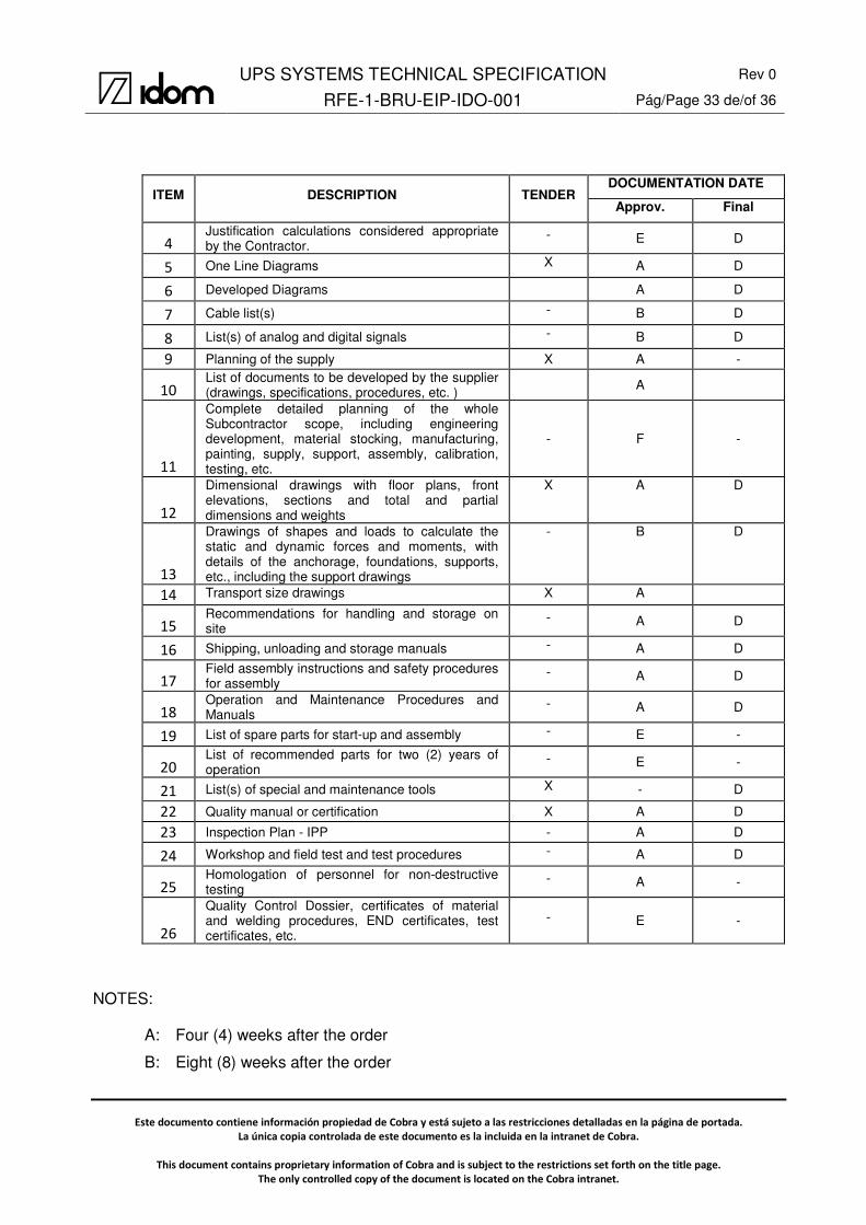
The Subcontractor must provide the documentation stated below:
ITEM DESCRIPTION TENDER DOCUMENTATION DATE
Approv. Final
1
Exact definition of the scope of the supply (including the deviation list). X - -
2 List of subcontractors X - -
3
Technical data sheet filled in (including guaranteed values) X - A
UPS SYSTEMS TECHNICAL SPECIFICATION Rev 0
RFE-1-BRU-EIP-IDO-001 Pág/Page 33 de/of 36
Este documento contiene información propiedad de Cobra y está sujeto a las restricciones detalladas en la página de portada.
La única copia controlada de este documento es la incluida en la intranet de Cobra.
This document contains proprietary information of Cobra and is subject to the restrictions set forth on the title page.
The only controlled copy of the document is located on the Cobra intranet.
ITEM DESCRIPTION TENDER DOCUMENTATION DATE
Approv. Final
4
Justification calculations considered appropriate by the Contractor.
- E D
5 One Line Diagrams X A D
6 Developed Diagrams A D
7 Cable list(s) - B D
8 List(s) of analog and digital signals - B D
9 Planning of the supply X A -
10
List of documents to be developed by the supplier (drawings, specifications, procedures, etc. ) A
11
Complete detailed planning of the whole Subcontractor scope, including engineering development, material stocking, manufacturing, painting, supply, support, assembly, calibration, testing, etc.
- F -
12
Dimensional drawings with floor plans, front elevations, sections and total and partial dimensions and weights
X A D
13
Drawings of shapes and loads to calculate the static and dynamic forces and moments, with details of the anchorage, foundations, supports, etc., including the support drawings
- B D
14 Transport size drawings X A
15
Recommendations for handling and storage on site
- A D
16 Shipping, unloading and storage manuals - A D
17
Field assembly instructions and safety procedures for assembly
- A D
18
Operation and Maintenance Procedures and Manuals
- A D
19 List of spare parts for start-up and assembly - E -
20
List of recommended parts for two (2) years of operation
- E -
21 List(s) of special and maintenance tools X - D
22 Quality manual or certification X A D
23 Inspection Plan - IPP - A D
24 Workshop and field test and test procedures - A D
25
Homologation of personnel for non-destructive testing
- A -
26
Quality Control Dossier, certificates of material and welding procedures, END certificates, test certificates, etc.
- E -
NOTES:
A: Four (4) weeks after the order
B: Eight (8) weeks after the order
UPS SYSTEMS TECHNICAL SPECIFICATION Rev 0
RFE-1-BRU-EIP-IDO-001 Pág/Page 34 de/of 36
Este documento contiene información propiedad de Cobra y está sujeto a las restricciones detalladas en la página de portada.
La única copia controlada de este documento es la incluida en la intranet de Cobra.
This document contains proprietary information of Cobra and is subject to the restrictions set forth on the title page.
The only controlled copy of the document is located on the Cobra intranet.
D: One (1) week after the comments or approval
E: Before the provisional reception
F: Monthly update until conclusion of the activities
The Subcontractor shall deliver the quantity of copies of the documentation that will be agreed at
the kick-off meeting or on signing the contract.

UPS SYSTEMS TECHNICAL SPECIFICATION Rev 0
RFE-1-BRU-EIP-IDO-001 Pág/Page 35 de/of 36
Este documento contiene información propiedad de Cobra y está sujeto a las restricciones detalladas en la página de portada.
La única copia controlada de este documento es la incluida en la intranet de Cobra.
This document contains proprietary information of Cobra and is subject to the restrictions set forth on the title page.
The only controlled copy of the document is located on the Cobra intranet.
11. ANNEXES
Annex 1: List of UPS Plant feeders
Annex 2: List of UPS Control Room feeders

UPS SYSTEMSTECHNICAL SPECIFICATION
Rev. 0
RFE-1-BRU-EIP-IDO-001 ANNEX 1 Pág/Page 1 de/of 3
ANNEX 1:
LIST OF UPS PLANT FEEDERS.

UPS SYSTEMSTECHNICAL SPECIFICATION
Rev. 0
RFE-1-BRU-EIP-IDO-001 ANNEX 1 Pág/Page 2 de/of 3
KKS DESCRIPTIONVOLTAGE
Un (V)PHASES POT. (kW) POT. (kVA)
Irated (A) @ Un
CIRCUIT BREAKER (A)
1BRA51
1EGA11CF001-P01CAUDALIMETRO 1 RED APORTE COMBUSTIBLE
220 R+S+PE 0,30 0,35 1,60 10
1GAF11CF001-P01CAUDALIMETRO 1 RED APORTE AGUA BRUTA
220 S+T+PE 0,30 0,35 1,60 10
PENDIENTE PLC SISTEMA PTA 220 R+T+PE 1,50 1,76 8,02 16
PENDIENTEPLC GRUPO DIESEL DE EMERGENCIA (1)
220 S+T+PE 1,00 1,18 5,35 10
PENDIENTE RACK 1 DEL DCS (1) 220 R+S+PE 3,00 3,53 16,04 20
PENDIENTE RACK 2 DEL DCS (1) 220 S+T+PE 3,00 3,53 16,04 20
PENDIENTERACK TELECOMUNICACIONES (1)
220 R+T+PE 3,00 3,53 16,04 20
PENDIENTEGENERADOR AUXILIAR (SAI) (2)
220 S+T+PE 4,00 4,71 21,39 25
1BRB11 TURBINA GAS (UPS -1) 127 T+N+PE 2,00 2,35 18,53 25
PENDIENTESISTEMA DE MONITORIZACIÓN DE EMISIONES (CEMS)
220 R+S+PE 5,00 5,88 26,74 32
SPARE (RESERVA) R+S+PE 10
SPARE (RESERVA) R+T+PE 10
SPARE (RESERVA) R+T+PE 20

UPS SYSTEMSTECHNICAL SPECIFICATION
Rev. 0
RFE-1-BRU-EIP-IDO-001 ANNEX 1 Pág/Page 3 de/of 3
KKS DESCRIPTIONVOLTAGE
Un (V)PHASES POT. (kW) POT. (kVA)
Irated (A) @ Un
CIRCUIT BREAKER (A)
1BRA52
1EGA21CF001-P01CAUDALIMETRO 2 RED APORTE COMBUSTIBLE
220 R+S+PE 0,30 0,35 1,60 10
1GAF21CF001-P01CAUDALIMETRO 2 RED APORTE AGUA BRUTA
220 S+T+PE 0,30 0,35 1,60 10
PENDIENTE PLC SISTEMA PCI 220 R+T+PE 1,00 1,18 5,35 10
PENDIENTEPLC SISTEMA AIRE COMPRIMIDO
220 S+T+PE 1,00 1,18 5,35 10
PENDIENTEPLC GRUPO DIESEL DE EMERGENCIA (2)
220 R+S+PE 1,00 1,18 5,35 10
PENDIENTE RACK 1 DEL DCS (2) 220 S+T+PE 3,00 3,53 16,04 20
PENDIENTE RACK 2 DEL DCS (2) 220 R+T+PE 3,00 3,53 16,04 20
PENDIENTERACK TELECOMUNICACIONES (2)
220 S+T+PE 3,00 3,53 16,04 20
PENDIENTEGENERADOR AUXILIAR (SAI) (1)
220 R+N+PE 4,00 4,71 21,39 25
1BRB11 TURBINA GAS (UPS -2) 127 R+S+PE 2,00 2,35 18,53 25
SPARE (RESERVA) S+T+PE 10
SPARE (RESERVA) R+T+PE 10
SPARE (RESERVA) S+T+PE 20

UPS SYSTEMSTECHNICAL SPECIFICATION
Rev. 0
RFE-1-BRU-EIP-IDO-001 ANNEX 2 Pág/Page 1 de/of 2
ANNEX 2:
LIST OF UPS CONTROL ROOM FEEDERS.

UPS SYSTEMSTECHNICAL SPECIFICATION
Rev. 0
RFE-1-BRU-EIP-IDO-001 ANNEX 2 Pág/Page 2 de/of 2
KKS DESCRIPTIONVOLTAGE
Un (V)PHASES POT. (kW) POT. (kVA)
Irated (A) @ Un
CIRCUIT BREAKER (A)
CONTROL ROOM UPS
PENDIENTECENTRALITA CONTRAINCENDIOS
220 R+S+PE 0,50 0,59 2,67 10
PENDIENTE SISTEMA MEGAFONIA 220 S+T+PE 1,50 1,76 8,02 16
PENDIENTE RACK TELECOMUNICACIONES 220 R+T+PE 1,50 1,76 8,02 16
PENDIENTE SISTEMA CCTV 220 R+S+PE 1,50 1,76 8,02 16
PENDIENTE ESTACIÓN DE OPERACIÓN 220 S+T+PE 0,70 0,82 3,74 10
PENDIENTEESTACIÓN OPERACIÓN DE LA TURBINA GAS
127 T+N+PE 0,50 0,59 4,63 10
PENDIENTEESTACIÓN DE OPERACIÓN CEMS
220 R+T+PE 0,50 0,59 2,67 10
PENDIENTEESTACIÓN DE OPERACIÓN GENERADOR AUXILIAR
220 R+S+PE 0,50 0,59 2,67 10
PENDIENTEESTACIÓN DE INGENIERÍA, HISTÓRICOS Y ALARMAS
220 S+T+PE 0,50 0,59 2,67 10
PENDIENTE SERVIDOR DE HISTÓRICOS 220 R+T+PE 0,50 0,59 2,67 10
PENDIENTESISTEMA SINCRONIZACIÓN HORARIA (GPS)
220 R+S+PE 0,30 0,35 1,60 10
PENDIENTE IMPRESORA B/N OPERACIÓN 220 S+T+PE 1,20 1,41 6,42 16
PENDIENTEIMPRESORA B/N REGISTRO ALARMAS
220 R+T+PE 0,20 0,24 1,07 10
PENDIENTESWITCHES DE LA TURBINA GAS
127 R+N+PE 0,60 0,71 5,56 10
SPARE (RESERVA) R+S+PE 10
SPARE (RESERVA) S+T+PE 10
SPARE (RESERVA) R+T+PE 16