rfid and nfc basics uni. of applied sciences jena...
TRANSCRIPT
RFID and NFCBasics
Uni. of Applied Sciences Jena24-06-2015
Konstantin Aslanidis
Texas Instruments Deutschland GmbHMCU Safety & SecurityProduct Line NFC, Animal ID & RFID
email: [email protected]: http://www.ti.com/rfid
Prof. Dr. Bernd Ploss
University of Applied Sciences JenaDepartment of SciTec
Email: [email protected]: http://www.fh-jena.de/~ploss
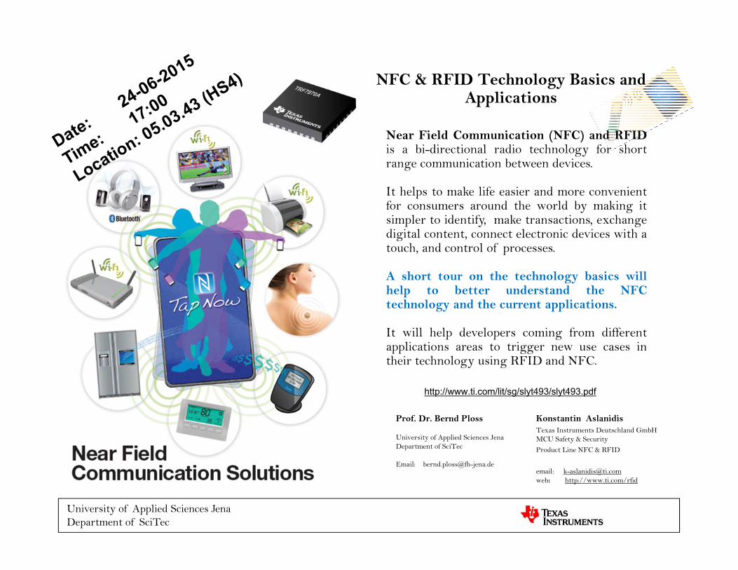
Near Field Communication (NFC) and RFIDis a bi-directional radio technology for shortrange communication between devices.
It helps to make life easier and more convenientfor consumers around the world by making itsimpler to identify, make transactions, exchangedigital content, connect electronic devices with atouch, and control of processes.
A short tour on the technology basics willhelp to better understand the NFCtechnology and the current applications.
It will help developers coming from differentapplications areas to trigger new use cases intheir technology using RFID and NFC.
NFC & RFID Technology Basics and Applications
Konstantin AslanidisTexas Instruments Deutschland GmbHMCU Safety & SecurityProduct Line NFC & RFID
email: [email protected]: http://www.ti.com/rfid
University of Applied Sciences JenaDepartment of SciTec
Prof. Dr. Bernd Ploss
University of Applied Sciences JenaDepartment of SciTec
Email: [email protected]
http://www.ti.com/lit/sg/slyt493/slyt493.pdf
6/24/2015 3
Content
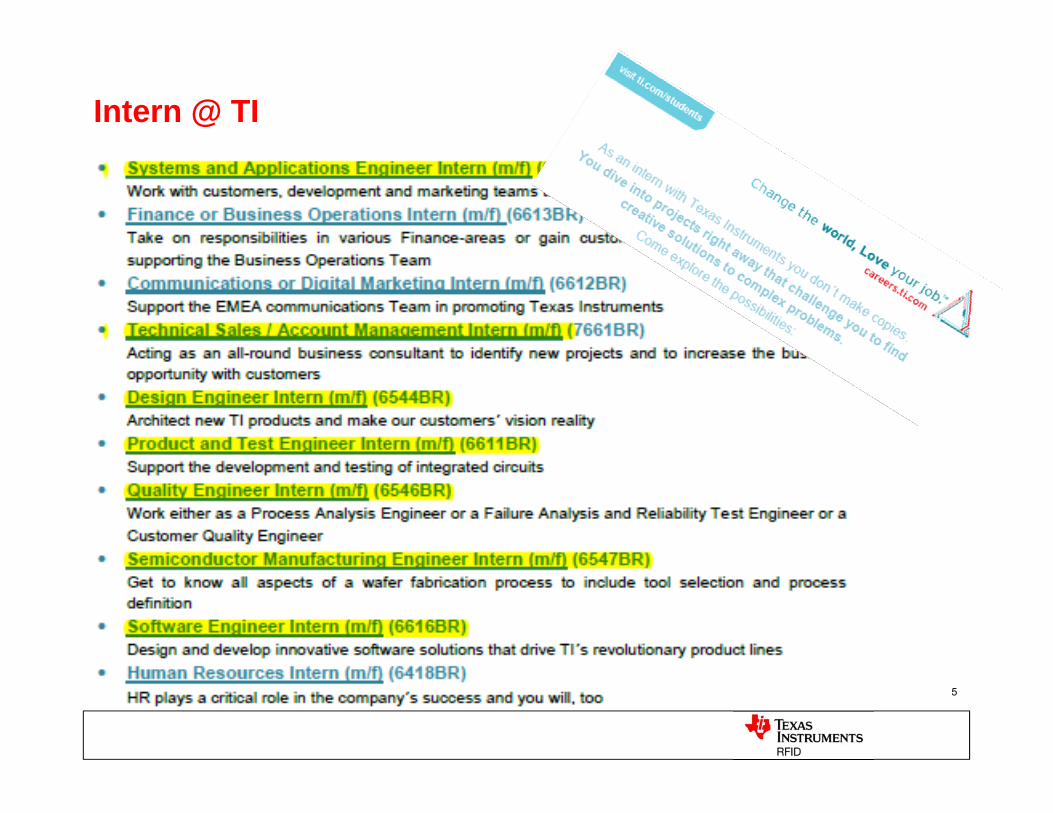
Intern @ TI – TI Web Links What’s RFID How does RFID work
RFID Technologies HF Tag Technology– 13.56MHz
What’s RFID NFC Technology NFC Devices and Tags
TRF7970 Near Field Communication (NFC) Transceiver IC RF430CL330H Dynamic Tag RF430FRL152H Sensor Tag
NFC Application Open Discussion
6/24/2015 4
TI – RFID / NFC LinksReferences / Links:
TI General: http://www.ti.com/
NFC/RFID: http://www.ti.com/lsds/ti/wireless_connectivity/nfc_rfid/overview.page
TRF7970A: http://www.ti.com/product/trf7970a
TRF7970A EVM: http://www.ti.com/tool/trf7970aevmhttp://www.ti.com/tool/trf7970atb
RF430CL330H: http://www.ti.com/product/rf430cl330hRF430CL330H EVM: http://www.ti.com/tool/rf430cl330htb
RF430FRL152H: http://www.ti.com/product/rf430frl152h
TI NFC Brochure: http://www.ti.com/lit/sg/slyt493a/slyt493a.pdf
TI University Program: http://www.ti.com/lsds/ti/university_program/ti_university_program.page
Werksstudenten / Praktika: http://careers.ti.com/content/ti-deutschland-0
6/24/2015 5
Intern @ TI
6/24/2015 6
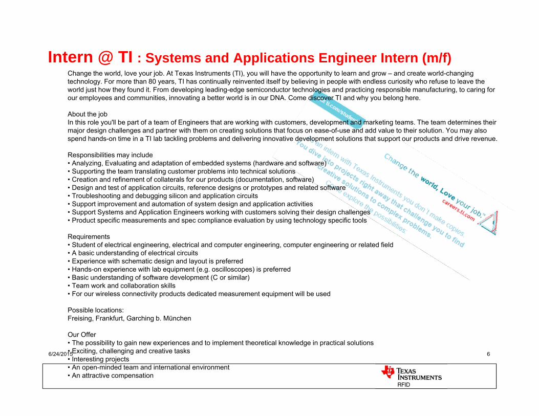
Intern @ TI : Systems and Applications Engineer Intern (m/f)Change the world, love your job. At Texas Instruments (TI), you will have the opportunity to learn and grow – and create world-changing technology. For more than 80 years, TI has continually reinvented itself by believing in people with endless curiosity who refuse to leave the world just how they found it. From developing leading-edge semiconductor technologies and practicing responsible manufacturing, to caring for our employees and communities, innovating a better world is in our DNA. Come discover TI and why you belong here.
About the job In this role you'll be part of a team of Engineers that are working with customers, development and marketing teams. The team determines their major design challenges and partner with them on creating solutions that focus on ease-of-use and add value to their solution. You may also spend hands-on time in a TI lab tackling problems and delivering innovative development solutions that support our products and drive revenue.
Responsibilities may include • Analyzing, Evaluating and adaptation of embedded systems (hardware and software) • Supporting the team translating customer problems into technical solutions • Creation and refinement of collaterals for our products (documentation, software) • Design and test of application circuits, reference designs or prototypes and related software • Troubleshooting and debugging silicon and application circuits • Support improvement and automation of system design and application activities • Support Systems and Application Engineers working with customers solving their design challenges • Product specific measurements and spec compliance evaluation by using technology specific tools
Requirements • Student of electrical engineering, electrical and computer engineering, computer engineering or related field • A basic understanding of electrical circuits • Experience with schematic design and layout is preferred • Hands-on experience with lab equipment (e.g. oscilloscopes) is preferred • Basic understanding of software development (C or similar) • Team work and collaboration skills • For our wireless connectivity products dedicated measurement equipment will be used
Possible locations: Freising, Frankfurt, Garching b. München
Our Offer • The possibility to gain new experiences and to implement theoretical knowledge in practical solutions • Exciting, challenging and creative tasks • Interesting projects • An open-minded team and international environment • An attractive compensation
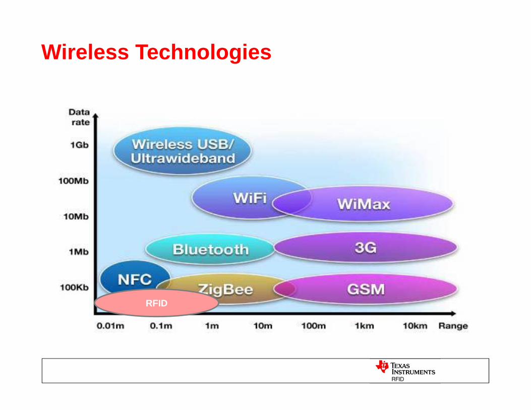
Wireless Technologies
RFID
6/24/2015 8
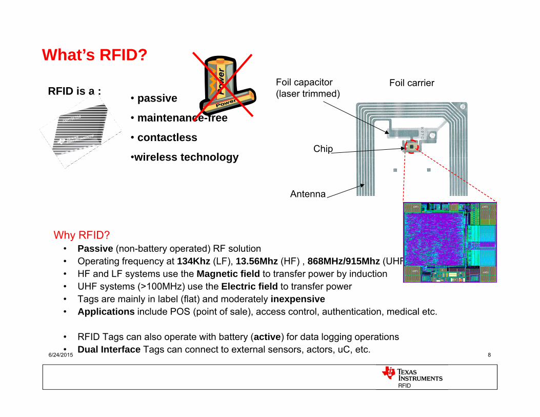
RFID is a :
Why RFID?• Passive (non-battery operated) RF solution• Operating frequency at 134Khz (LF), 13.56Mhz (HF) , 868MHz/915Mhz (UHF)• HF and LF systems use the Magnetic field to transfer power by induction• UHF systems (>100MHz) use the Electric field to transfer power• Tags are mainly in label (flat) and moderately inexpensive• Applications include POS (point of sale), access control, authentication, medical etc.
• RFID Tags can also operate with battery (active) for data logging operations• Dual Interface Tags can connect to external sensors, actors, uC, etc.
• passive
• maintenance-free
• contactless
•wireless technology
• passive
• maintenance-free
• contactless
•wireless technology
What’s RFID?Foil capacitor(laser trimmed)
Antenna
Chip
Foil carrier
6/24/2015 9
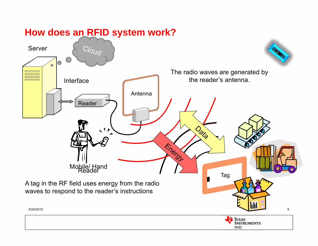
The radio waves are generated by the reader’s antenna.
A tag in the RF field uses energy from the radio waves to respond to the reader’s instructions
Tag
Interface
Antenna
Reader
How does an RFID system work?Server
Mobile/ Hand Reader
6/24/2015 10
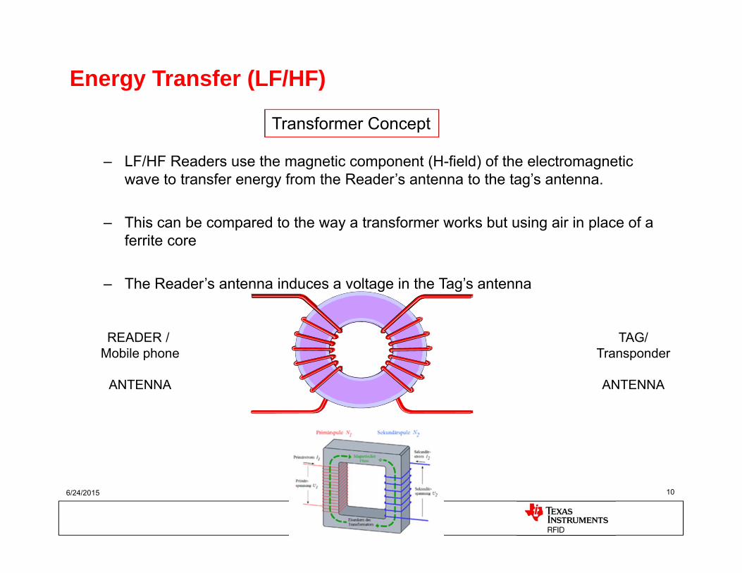
TAG/Transponder
ANTENNA
READER / Mobile phone
ANTENNA
– LF/HF Readers use the magnetic component (H-field) of the electromagnetic wave to transfer energy from the Reader’s antenna to the tag’s antenna.
– This can be compared to the way a transformer works but using air in place of a ferrite core
– The Reader’s antenna induces a voltage in the Tag’s antenna
Energy Transfer (LF/HF)
Transformer Concept
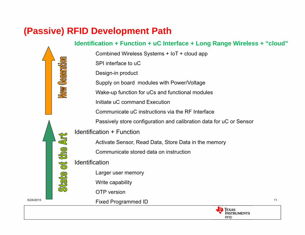
Identification + Function + uC Interface + Long Range Wireless + “cloud”Combined Wireless Systems + IoT + cloud app
SPI interface to uC
Design-in product
Supply on board modules with Power/Voltage
Wake-up function for uCs and functional modules
Initiate uC command Execution
Communicate uC instructions via the RF Interface
Passively store configuration and calibration data for uC or Sensor
Identification + FunctionActivate Sensor, Read Data, Store Data in the memory
Communicate stored data on instruction
Identification Larger user memory
Write capability
OTP version
Fixed Programmed ID6/24/2015 11
(Passive) RFID Development Path
6/24/2015 12
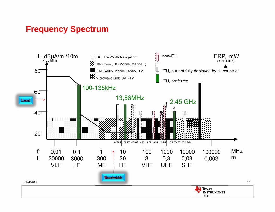
Frequency Spectrum
80
60
40
20
0,0130000VLF
0,13000LF
1300MF
1030HF
1003
VHF
10000,3
UHF
100000,03SHF
1000000,003
f:l:
MHzm
H, dBµA/m /10m(< 30 MHz)
ERP, mW(> 30 MHz)
FM Radio, Mobile Radio , TV
SW (Com., BC,Mobile, Marine...)
BC, LW-/MW- Navigation
Microwave Link, SAT-TV
100-135kHz
2.45 GHz13,56MHz
6.7813.5627 40.68 433 868, 915 2.450 5.800 77.000 MHz
non-ITU
ITU, but not fully deployed by all countries
ITU, preferred
6/24/2015 13
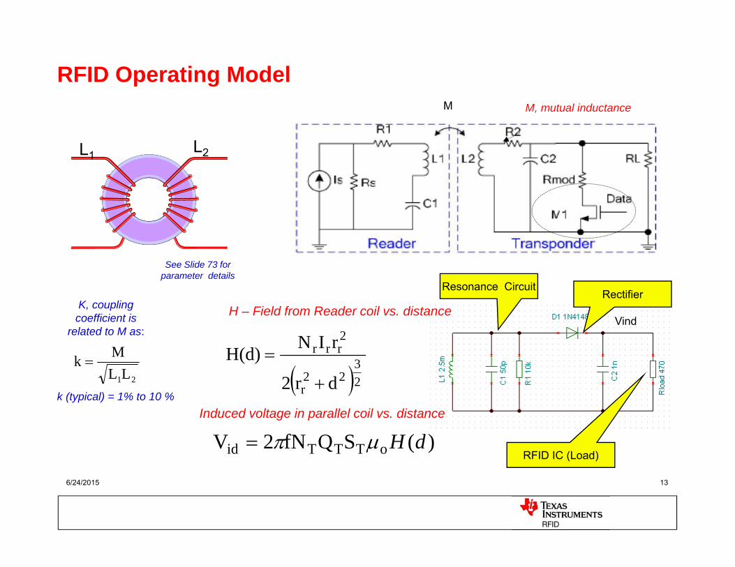
RFID Operating Model
H – Field from Reader coil vs. distance
23
22r
2rrr
dr2
rINH(d)
Induced voltage in parallel coil vs. distance
)(SQfN2V oTTTid dH
M, mutual inductanceM
21LLMk
K, coupling coefficient is
related to M as:
k (typical) = 1% to 10 %
Resonance CircuitRectifier
RFID IC (Load)
Vind
L1 L2
See Slide 73 for parameter details
6/24/2015 14
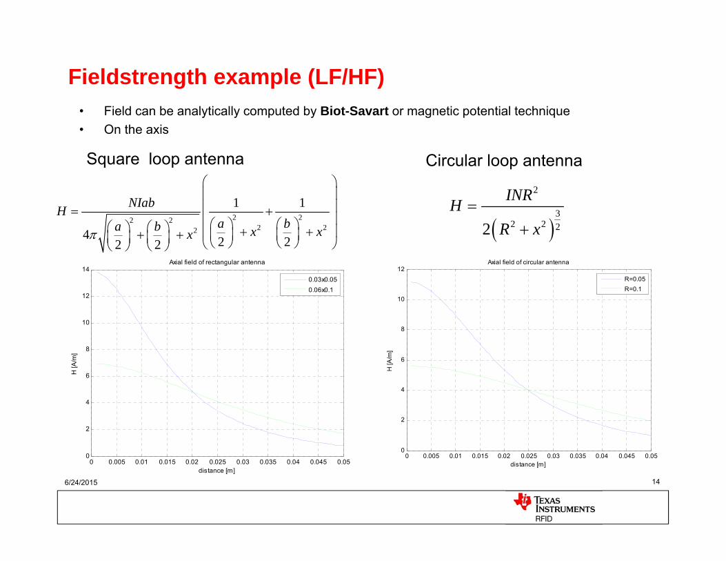
Fieldstrength example (LF/HF)• Field can be analytically computed by Biot-Savart or magnetic potential technique• On the axis
2 22 22 22
1 1
4 2 22 2
NIabHa ba b x xx
0 0.005 0.01 0.015 0.02 0.025 0.03 0.035 0.04 0.045 0.050
2
4
6
8
10
12
14
distance [m]
H [A
/m]
Axial field of rectangular antenna
0.03x0.050.06x0.1
Square loop antenna
2
32 2 22
INRHR x
Circular loop antenna
0 0.005 0.01 0.015 0.02 0.025 0.03 0.035 0.04 0.045 0.050
2
4
6
8
10
12
distance [m]
H [A
/m]
Axial field of circular antenna
R=0.05R=0.1
16-01-2014 15
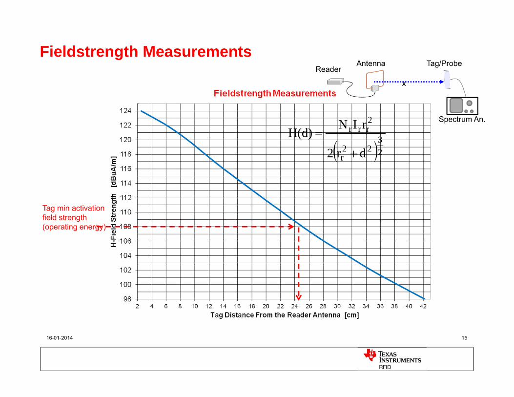
Fieldstrength Measurements
23
22r
2rrr
dr2
rINH(d)
Tag min activation field strength (operating energy)
AntennaReader
x
Tag/Probe
Spectrum An.
16-03-2010 16
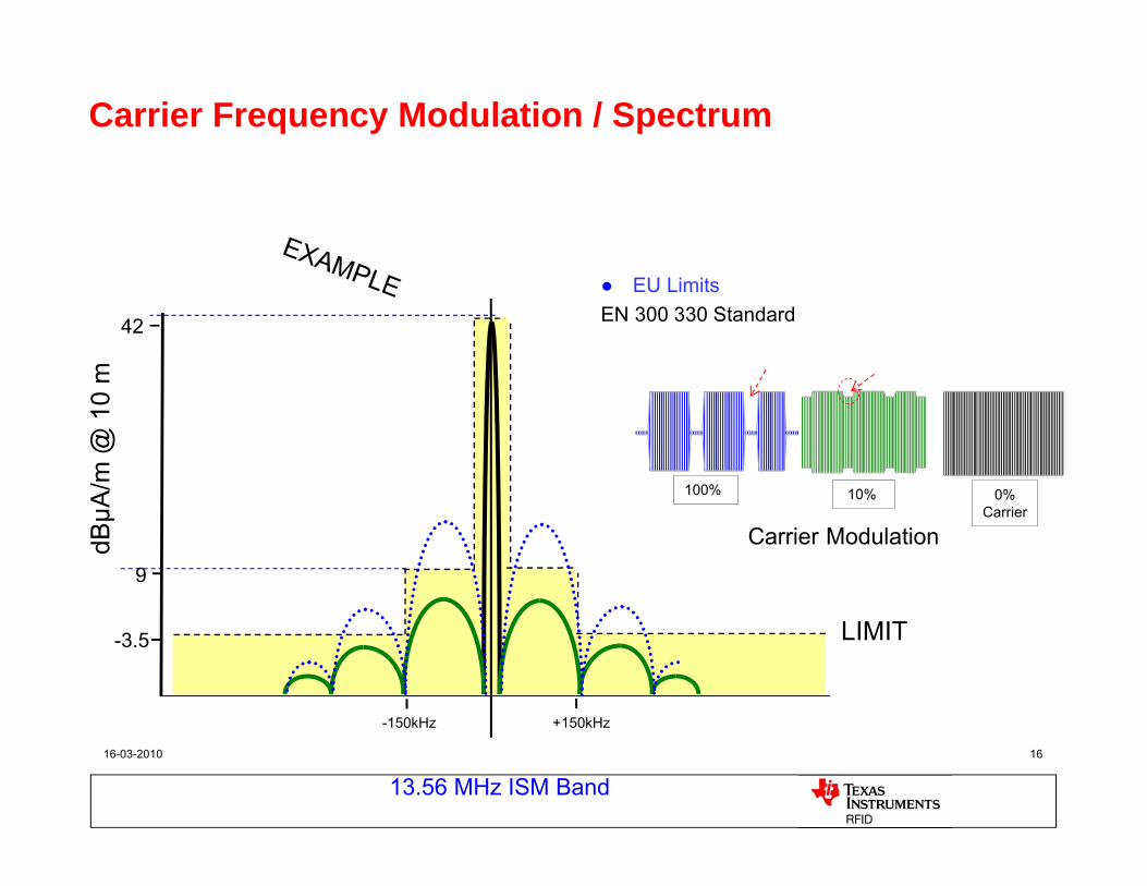
Carrier Frequency Modulation / Spectrum
LIMIT
EU LimitsEN 300 330 Standard
Carrier Modulation
100% 10% 0% Carrier
13.56 MHz ISM Band
9
42
dBµA
/m @
10
m
-3.5
-150kHz +150kHz
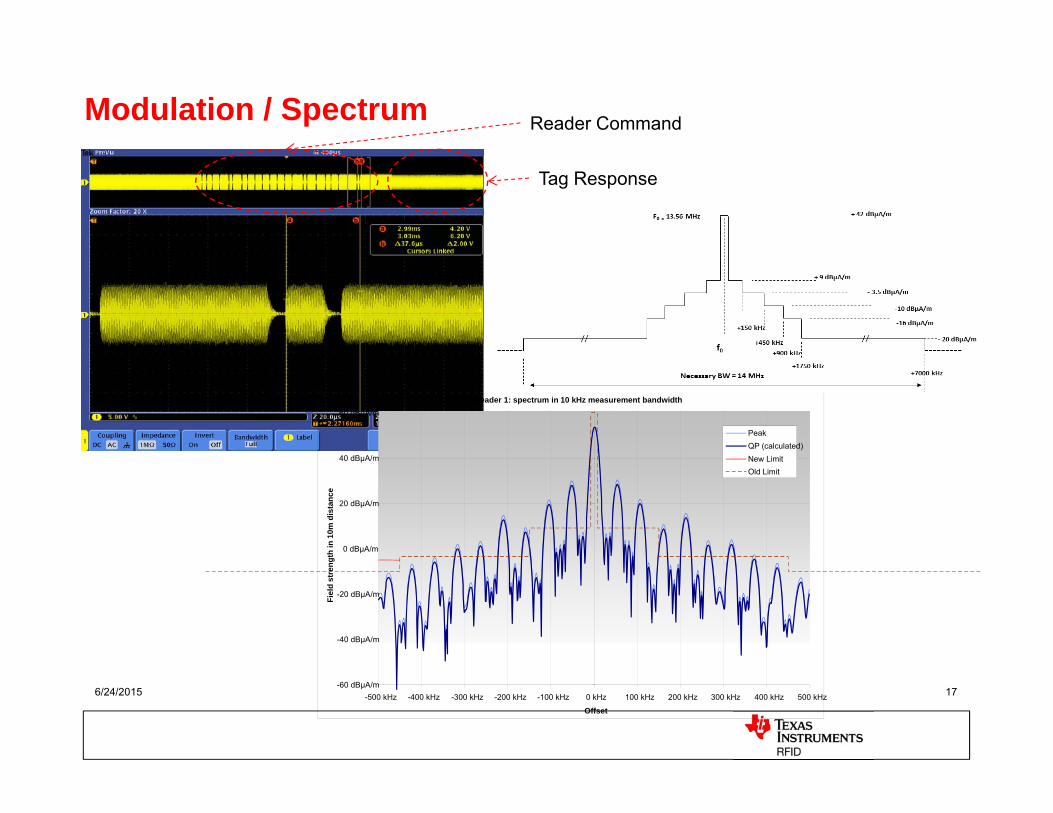
6/24/2015 17
Modulation / Spectrum
Reader 1: spectrum in 10 kHz measurement bandwidth
-60 dBµA/m
-40 dBµA/m
-20 dBµA/m
0 dBµA/m
20 dBµA/m
40 dBµA/m
60 dBµA/m
-500 kHz -400 kHz -300 kHz -200 kHz -100 kHz 0 kHz 100 kHz 200 kHz 300 kHz 400 kHz 500 kHz
Offset
Fiel
d st
reng
th in
10m
dis
tanc
e
PeakQP (calculated)New LimitOld Limit
Reader Command
Tag Response
6/24/2015 18
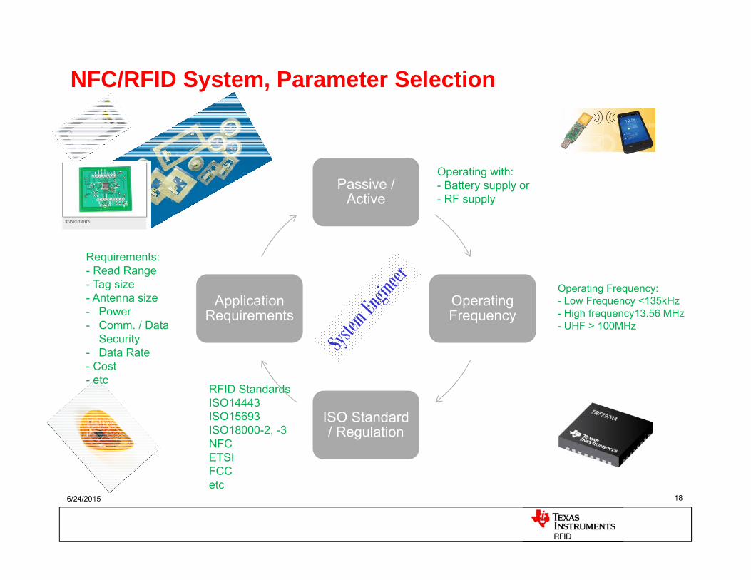
NFC/RFID System, Parameter Selection
Passive / Active
Operating Frequency
ISO Standard / Regulation
Application Requirements
Operating with: - Battery supply or- RF supply
Operating Frequency:- Low Frequency <135kHz- High frequency13.56 MHz- UHF > 100MHz
RFID StandardsISO14443ISO15693ISO18000-2, -3NFCETSIFCCetc
Requirements:- Read Range- Tag size- Antenna size- Power- Comm. / Data
Security- Data Rate- Cost- etc
6/24/2015 19
NFC Technology
NFC Forum group http://www.nfc-forum.org
20
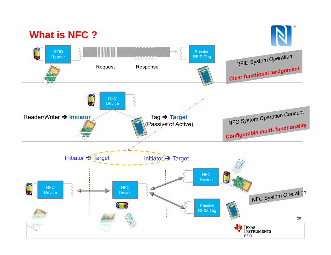
What is NFC ?
NFC Device
Reader/Writer Initiator Tag Target(Passive of Active)
NFC Device
NFC Device
NFC Device
PassiveRFID Tag
Initiator Target Initiator Target
RFID Reader
PassiveRFID Tag
Request Response
21
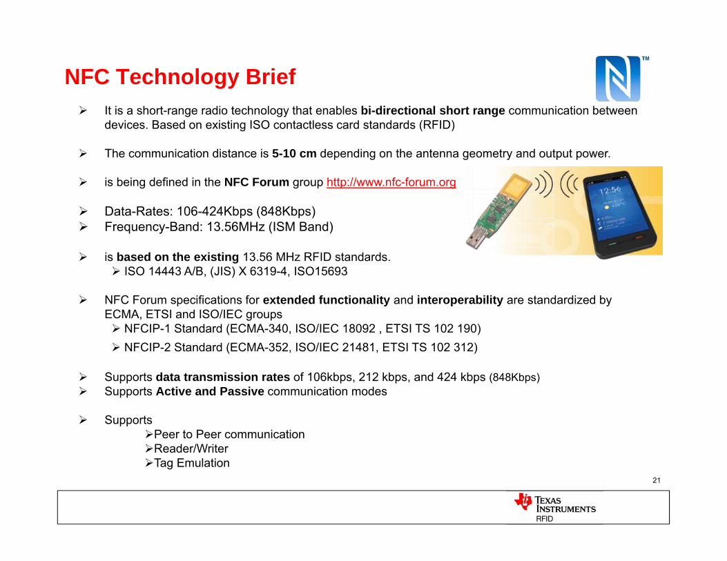
NFC Technology Brief It is a short-range radio technology that enables bi-directional short range communication between
devices. Based on existing ISO contactless card standards (RFID)
The communication distance is 5-10 cm depending on the antenna geometry and output power.
is being defined in the NFC Forum group http://www.nfc-forum.org
Data-Rates: 106-424Kbps (848Kbps) Frequency-Band: 13.56MHz (ISM Band)
is based on the existing 13.56 MHz RFID standards. ISO 14443 A/B, (JIS) X 6319-4, ISO15693
NFC Forum specifications for extended functionality and interoperability are standardized by ECMA, ETSI and ISO/IEC groups NFCIP-1 Standard (ECMA-340, ISO/IEC 18092 , ETSI TS 102 190) NFCIP-2 Standard (ECMA-352, ISO/IEC 21481, ETSI TS 102 312)
Supports data transmission rates of 106kbps, 212 kbps, and 424 kbps (848Kbps) Supports Active and Passive communication modes
SupportsPeer to Peer communicationReader/Writer Tag Emulation
22
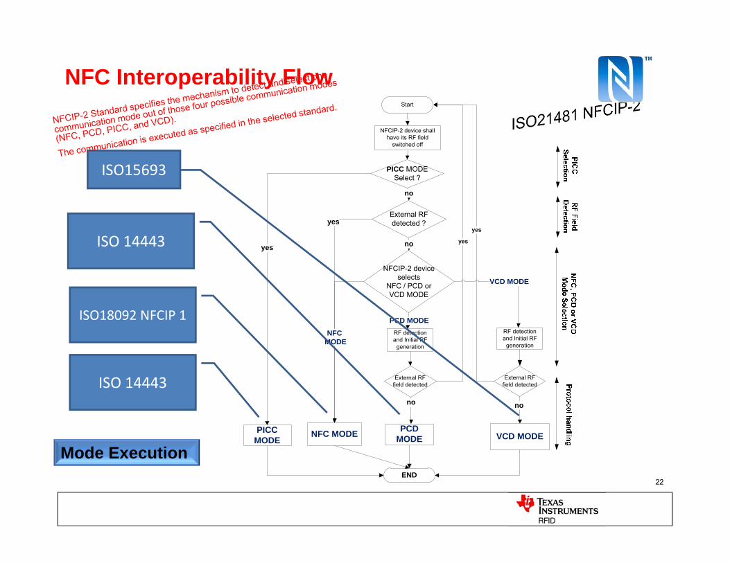
NFC Interoperability FlowStart
External RF detected ?
PCD MODE
END
NFC MODE VCD MODE
NFCIP-2 device selects
NFC / PCD or VCD MODE
yes
no
NFCMODE
no
External RF field detected
External RF field detected
no
NFCIP-2 device shall have its RF field
switched off
RF detection and Initial RF
generation
PCD MODERF detection and Initial RF
generation
VCD MODE
PICCMODE
PICC MODESelect ?
no
yes
yes
yes
Mode Execution
ISO15693
ISO 14443
ISO18092 NFCIP 1
ISO 14443
23
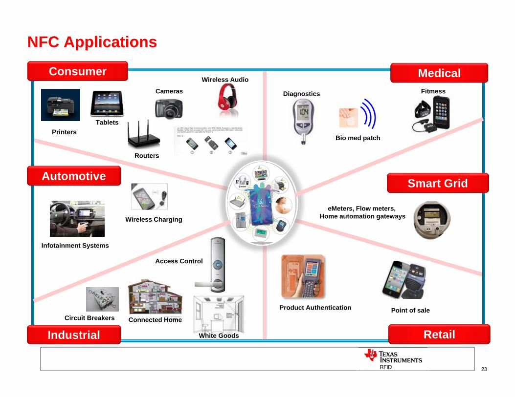
Consumer
PrintersTablets
Cameras
Wireless Audio
Routers
NFC Applications
Automotive
Infotainment Systems
Wireless Charging
Smart Grid
eMeters, Flow meters, Home automation gateways
Product Authentication Point of sale
Retail
Diagnostics
Medical
Bio med patch
Fitmess
IndustrialCircuit Breakers Connected Home
Access Control
White Goods
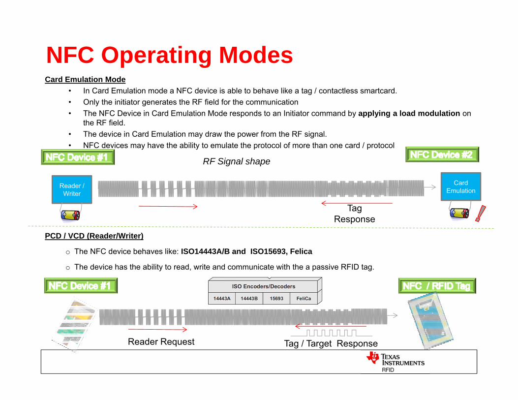
NFC Operating ModesCard Emulation Mode
• In Card Emulation mode a NFC device is able to behave like a tag / contactless smartcard. • Only the initiator generates the RF field for the communication• The NFC Device in Card Emulation Mode responds to an Initiator command by applying a load modulation on
the RF field.• The device in Card Emulation may draw the power from the RF signal.• NFC devices may have the ability to emulate the protocol of more than one card / protocol
PCD / VCD (Reader/Writer)
o The NFC device behaves like: ISO14443A/B and ISO15693, Felica
o The device has the ability to read, write and communicate with the a passive RFID tag.
Reader / Writer
CardEmulation
TagResponse
RF Signal shape
Reader Request Tag / Target Response
6/24/2015 25
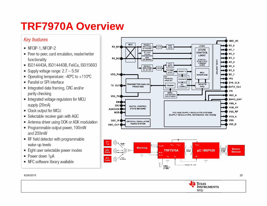
TRF7970A Overview
LEVEL SHIFTER
26
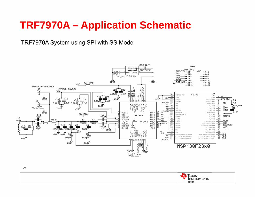
TRF7970A – Application Schematic TRF7970A System using SPI with SS Mode

+
= Ease in evaluation= Available Schematic, BOM, Gerber Files = Available Source Code = Quicker time to market
EVM Graphical User Interface
TRF7970A –Tools
TRF7970AEVM – Evaluation Kit
USB Interface
TRF7970ANFC Readerchip
MSP430F2370 13.56 MHz Xtal
Integrated PCBAntenna
LED Indicators(for auto run mode) +
Part-Number: TRF7970AEVM
For peer-to-peer communicationtwo EVMs are required
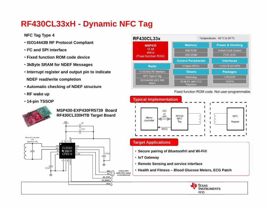
RF430CL33xH - Dynamic NFC Tag
• Secure pairing of Bluetooth® and Wi-Fi®
• IoT Gateway
• Remote Sensing and service interface
• Health and Fitness – Blood Glucose Meters, ECG Patch
Target Applications
Typical Implementation
Fixed function ROM code. Not user-programmable.
MSP430-EXP430FR5739 BoardRF430CL330HTB Target Board
NFC Tag Type 4
• ISO14443B RF Protocol Compliant
• I2C and SPI interface
• Fixed function ROM code device
• 3kByte SRAM for NDEF Messages
• Interrupt register and output pin to indicate
NDEF read/write completion
• Automatic checking of NDEF structure
• RF wake up
• 14-pin TSSOP
0
0,5
1
1,5
2
2,5
3
0 1 2 3 4 5 6 7
Volta
ge [V
]
Distance [cm]
Voltage (VCC) over Distance (Schottky)
TRF7970AEVM, 2.5x2.5 cm antenna
TRF7970AEVM, on-board antenna
TRF7970A, 1W PA with 5x5 ANT
Min. Operating Voltage
6/24/2015
TI Confidential – NDA Restrictions 29
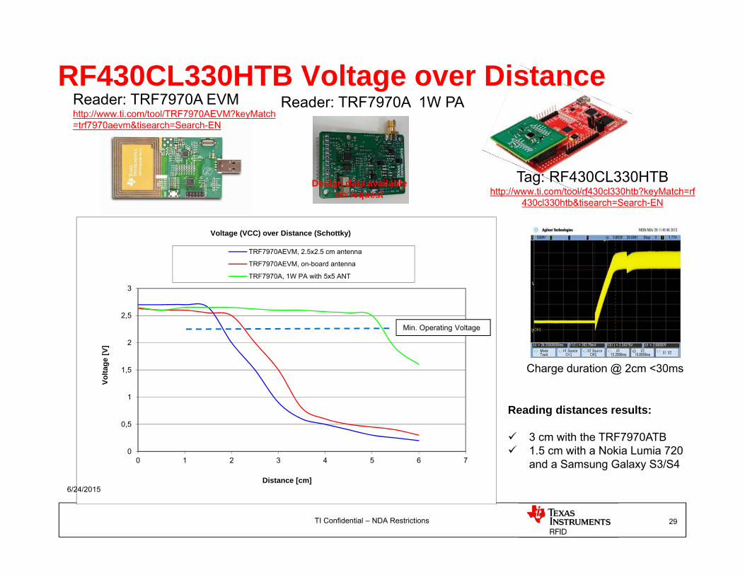
RF430CL330HTB Voltage over DistanceReader: TRF7970A EVMhttp://www.ti.com/tool/TRF7970AEVM?keyMatch=trf7970aevm&tisearch=Search-EN
Tag: RF430CL330HTB http://www.ti.com/tool/rf430cl330htb?keyMatch=rf
430cl330htb&tisearch=Search-EN
Reader: TRF7970A 1W PA
Charge duration @ 2cm <30ms
Reading distances results:
3 cm with the TRF7970ATB 1.5 cm with a Nokia Lumia 720
and a Samsung Galaxy S3/S4
Design data available on request
6/24/2015
TI Confidential – NDA Restrictions 30
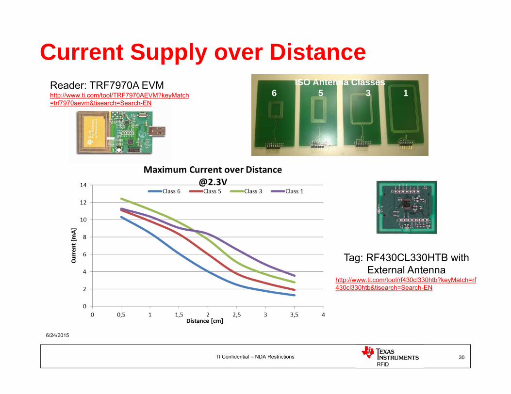
Current Supply over DistanceISO Antenna Classes
6 5 3 1Reader: TRF7970A EVMhttp://www.ti.com/tool/TRF7970AEVM?keyMatch=trf7970aevm&tisearch=Search-EN
Tag: RF430CL330HTB withExternal Antenna
http://www.ti.com/tool/rf430cl330htb?keyMatch=rf430cl330htb&tisearch=Search-EN
31
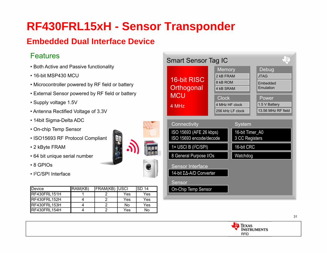
RF430FRL15xH - Sensor TransponderEmbedded Dual Interface Device
Smart Sensor Tag ICMemory
2 kB FRAM
Debug
8 kB ROM16-bit RISCOrthogonal MCU4 MHz
16-bit RISCOrthogonal MCU4 MHz
4 kB SRAM
JTAG
Embedded Emulation
SystemConnectivityISO 15693 (AFE 26 kbps)ISO 15693 encode/decode
16-bit Timer_A03 CC Registers
14-bit ΣΔ-A/D Converter
On-Chip Temp Sensor
1× USCI B (I2C/SPI) 16-bit CRC
8 General Purpose I/Os Watchdog
Sensor Interface
Sensor
PowerClock4 MHz HF clock
256 kHz LF clock
1.5 V Battery
13.56 MHz RF field
Features• Both Active and Passive functionality
• 16-bit MSP430 MCU
• Microcontroller powered by RF field or battery
• External Sensor powered by RF field or battery
• Supply voltage 1.5V
• Antenna Rectified Voltage of 3.3V
• 14bit Sigma-Delta ADC
• On-chip Temp Sensor
• ISO15693 RF Protocol Compliant
• 2 kByte FRAM
• 64 bit unique serial number
• 8 GPIOs
• I2C/SPI Interface
Device RAM(KB) FRAM(KB) USCI SD 14RF430FRL151H 1 2 Yes YesRF430FRL152H 4 2 Yes YesRF430FRL153H 4 2 No YesRF430FRL154H 4 2 Yes No
6/24/2015 TI Confidential – NDA Restrictions
32
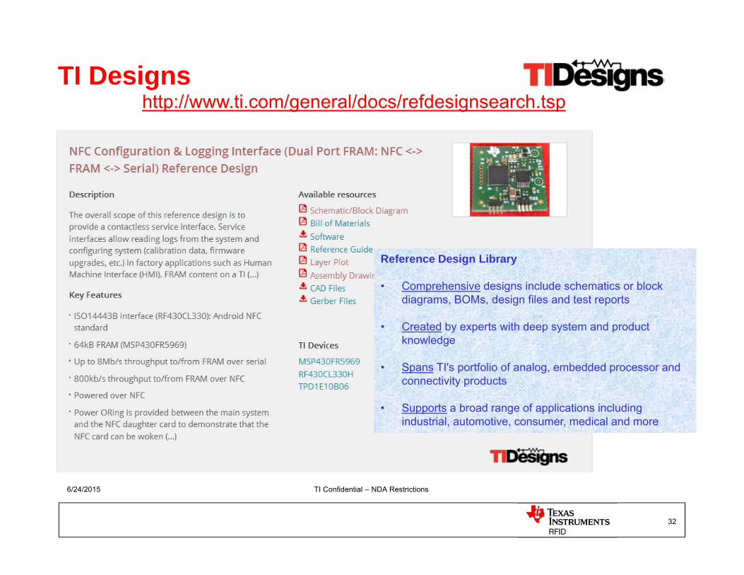
TI Designshttp://www.ti.com/general/docs/refdesignsearch.tsp
Reference Design Library
• Comprehensive designs include schematics or block diagrams, BOMs, design files and test reports
• Created by experts with deep system and product knowledge
• Spans TI's portfolio of analog, embedded processor and connectivity products
• Supports a broad range of applications including industrial, automotive, consumer, medical and more
6/24/2015
33
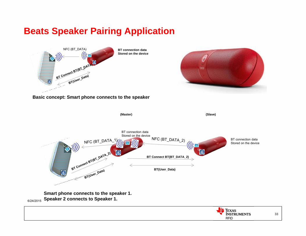
Beats Speaker Pairing ApplicationNFC (BT_DATA) BT connection data
Stored on the device
Basic concept: Smart phone connects to the speaker
BT connection dataStored on the device
BT connection dataStored on the device
BT Connect BT(BT_DATA_2)
BT(User_Data)
(Master) (Slave)
Smart phone connects to the speaker 1.Speaker 2 connects to Speaker 1.

6/24/2015
34
Non invasive disposable sensors for different vessels
Continuous multi-parameter monitoringBattery less Sensor into the Petri dish
Isolated DC/DC
Isolated Data
DC/DC
Power Supply
MCU
Sensor
MCU
Galvanic Isolation
6/24/2015
35
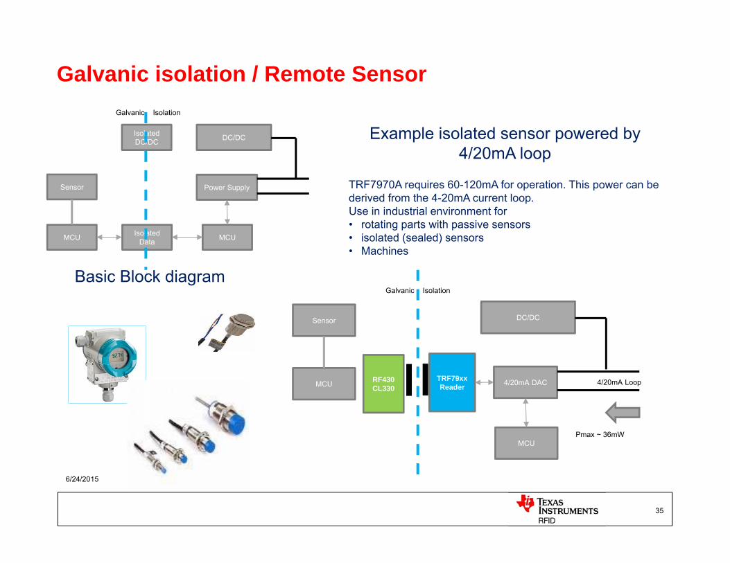
Galvanic isolation / Remote Sensor
DC/DC
4/20mA DAC 4/20mA LoopMCU
Sensor
MCU
Galvanic Isolation
Pmax ~ 36mW
TRF79xxReader
RF430CL330
Example isolated sensor powered by 4/20mA loop
Basic Block diagram
TRF7970A requires 60-120mA for operation. This power can be derived from the 4-20mA current loop.Use in industrial environment for • rotating parts with passive sensors • isolated (sealed) sensors• Machines

WLAN
36
RF430CL330H – Wireless Supply DEMO
CLOUD
WAN
Remote terminal
Embedded ARM Cortex A / Cortex M Processor
WiFiNetwork Processor
Integrated Ethernet PHY
Bluetooth Low Energy SoC
Power Management
Multi-Protocol Integrated 13.56-MHz RFID/NFC
Transceiver IC
LAN
DynamicNFC
Transponder Interface
Connectivity GatewayRemote terminal
ULP MCU
Sensor(s)
VCC
VCC
Wireless battery-lesssensor
Color LCD display
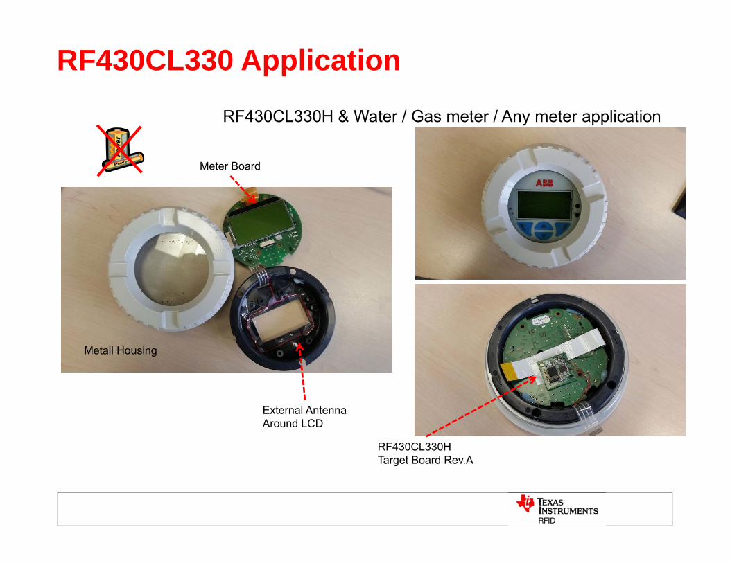
TI Wireless Connectivity PortfolioRF430CL330 Application
RF430CL330H & Water / Gas meter / Any meter application
External AntennaAround LCD
Metall Housing
Meter Board
RF430CL330H Target Board Rev.A
6/24/2015 38
Thank you for the attention
For Question and feedback, please contactKostas Aslanidis
6/24/2015 39
Back-up

LFHF
15693 onlyUHF
Frequency 120 to 134kHz 13.56MHz 840 to 960MHz
Wavelength 2500m 22m 30cm
Liquid Immunity excellent good poor
Data rates 12 kb/sec 27 kb/sec 640 Kb/sec
Read rates ~28 tags/sec ~50 tags/sec +100 tags/sec
Anticollision No Yes Yes
Read Range (typ) 0~2m 0~1m .1~10m
Tags / Inlays
6/24/2015 40
RFID Technology Matrix
6/24/2015 41
LF - HF Antenna Design Basics
TI Embedded RF
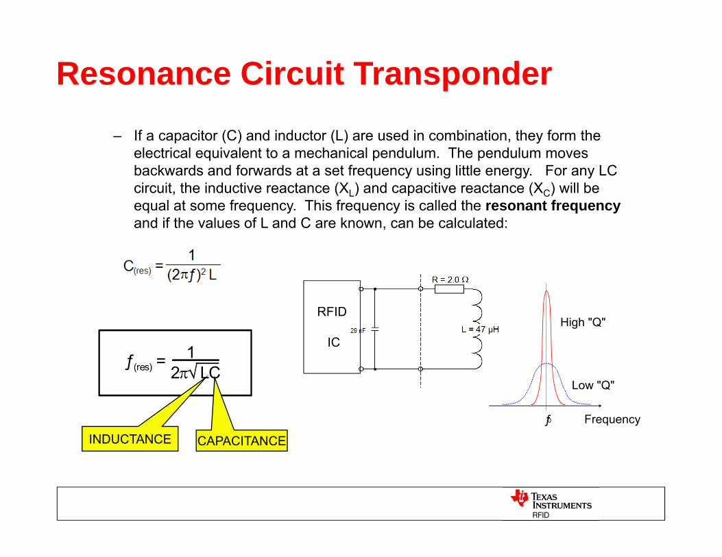
Resonance Circuit Transponder– If a capacitor (C) and inductor (L) are used in combination, they form the
electrical equivalent to a mechanical pendulum. The pendulum moves backwards and forwards at a set frequency using little energy. For any LC circuit, the inductive reactance (XL) and capacitive reactance (XC) will be equal at some frequency. This frequency is called the resonant frequency and if the values of L and C are known, can be calculated:
ƒ(res) = 12LC
High "Q"
Low "Q"
Frequencyƒ0
CAPACITANCEINDUCTANCE
RFID
IC
16-03-2010 “TI Information – Selective Disclosure” 43
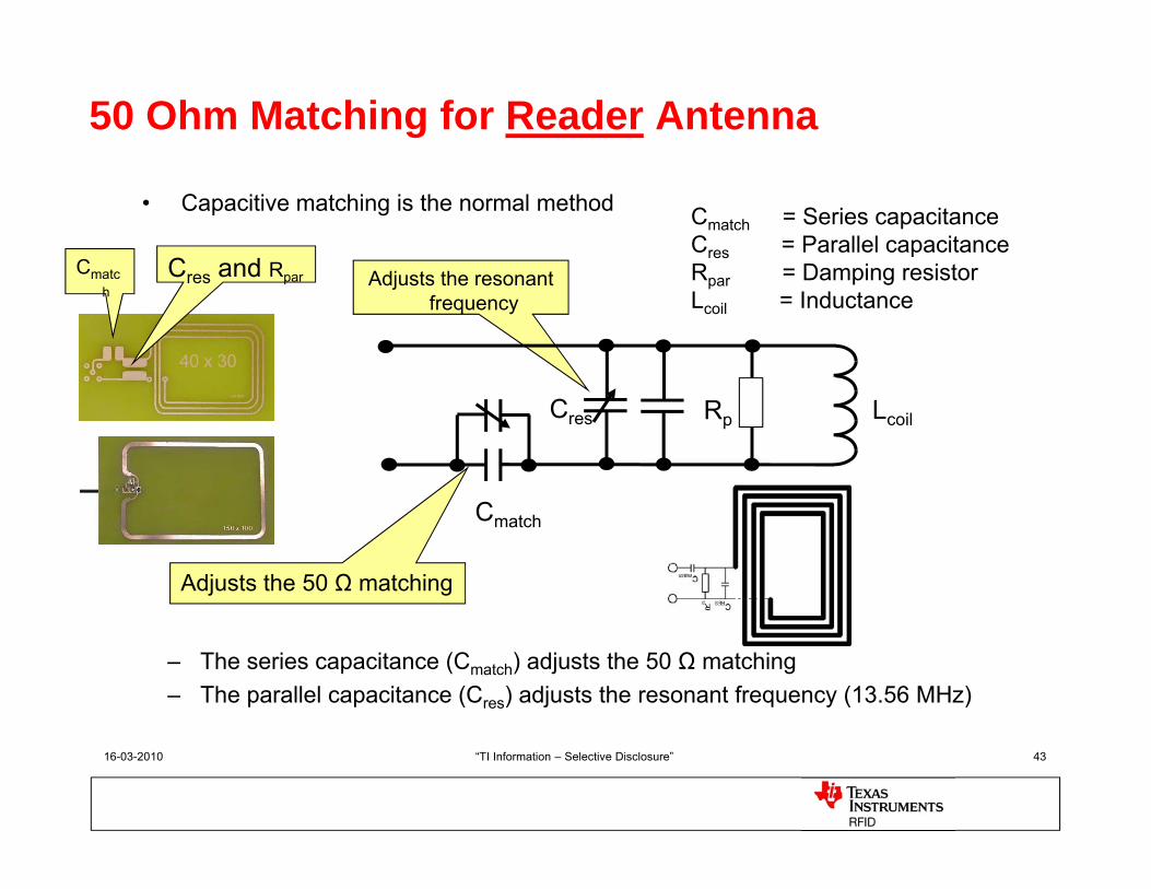
50 Ohm Matching for Reader Antenna
• Capacitive matching is the normal method
– The series capacitance (Cmatch) adjusts the 50 Ω matching– The parallel capacitance (Cres) adjusts the resonant frequency (13.56 MHz)
Adjusts the 50 Ω matching
Adjusts the resonant frequency
Cmatch
Cres Rp Lcoil
Cmatch = Series capacitanceCres = Parallel capacitanceRpar = Damping resistorLcoil = Inductance
Cmatch
Cres and Rpar
6/24/2015 44
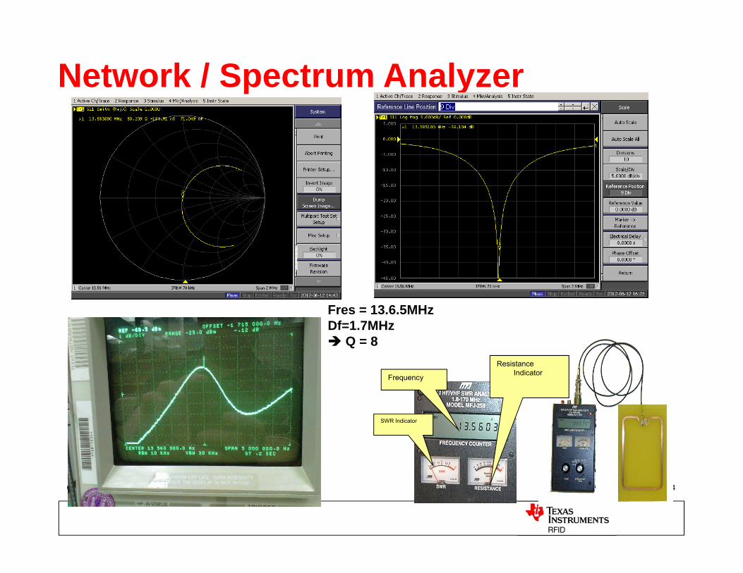
Network / Spectrum Analyzer
Fres = 13.6.5MHz Df=1.7MHz Q = 8
Frequency
SWR Indicator
Resistance Indicator