rf/microwave products - gigalane.co.krgigalane.co.kr/rf/down/1_full catalog_2016_edition.pdf ·...
TRANSCRIPT

Connectors
RF ConnectivityTest Solutions
MicrowaveCable
Assemblies
RF/MicrowaveProducts
Edition 2016
Adapters

Contents
At any time, to respond tothe needs of our customers, GigaLane is always on your side.GigaLane is a company specializing in high performance RF connector, cable and assembly which is
applicable to state-of-the-art technology for Telecom(Mobile Device & Network Infra),
Industrial, Aerospace and Medical industries.
GigaLane performs all activities from original design to mass production based
on its R&D and manufacturing competency.
RF products of GigaLane comply with all military standards in design, production, quality assuranceand etc.
GigaLane looks forward to growing together with its customers by enhancing customer
satisfaction through high quality and reasonable price.
GigaLane is always at your service.
Banwol
Asan
Dongtan
Introduction
2.4 mm Connector
2.92mm(K) Connectors
Installation of 2.4mm&2.92mm
SMP Connectors
BMA Connectors
High Performance End Launch connectors
High Performance SMA Connectors
SMA Connectors
MCX Connectors
MMCX Connectors
N-type Connectors
RF & MW Connectors08
10
12
14
17
19
27
29
32
34
36
03
Precision Adapters in Series
Precision Adapters between Series
SMP Adapters
BMA Adapters
Standard Adapters
RF & MW Adapters40
45
49
50
51
Board to Board Connector
SMA Quick Lock Cable Assembly
GigaLane Mobile Coaxial Micro-Plugs
GigaLane CMP Application Cable Assemblies
GigaLane Mobile Coaxial Micro-Test Solution
FRC(FPCB RF Cable)
RF Connectivity Test Solutions54
56
58
60
61
62
101
Test & Measurement3.5mm&N-Type&DIN Type Calibration Kits
TDR Probe
Attenuators
GL Series
GUL Series
Airborne Series
MF Series
SR Series
SF Series
Suitable Connectors for cable
Specifying Assembly Length
Cable Assemblies
Appendix
64
66
67
72
79
83
85
88
91
94
100
Factory (Hanoi, Vietnam) Factory (Yantai, China)
Factory (Korea)
HQ (Hwaseong, Korea)

To suit to the needs of our customers, GigaLane has developed these connectors for simple, fine feature and reliable quality. GigaLane’s connectors are satisfied with MIL standard and developed for applications such as Aerospace, Military, Broadband, Instrumentation and telecom.
Connectors
Microwave Cable Assemblies
GigaLane’s Adapters are ideal for lab and production test applications, where measure-ment accuracy, repeatability and optimum electrical performance are critical.
GigaLane is a company specialized in high performance RF cables which is applicableto state-of-the -art technology. GigaLane is a No 1 manufacturer of high frequency Low-Loss and assembly.
Adapters
Contributing to build smarter worldwith cutting edge RF technologies
GigaLane Co., Ltd. [email protected] www.gigalane.com6 7Where signal & Connectivity is needed, There is GigaLane
RF & M
W Connectors
RF & M
W Adapters
RF ConnectivityTest Solutions
Test & M
easurement
Cable Assemblies
Appendix
RF & MW Connectors- 2.4 mm Connectors - 2.92 mm(K) Connectors - Hermetic Seal (0.012” Glass Bead) - SMP Connectors - BMA Connectors - High Performance End Lanch Connectors - High Performance SMA Connectors - SMA Connectors - MCX Connectors - MMCX Connectors - N-Type Connectors

GigaLane Co., Ltd. [email protected] www.gigalane.com8 9Where signal & Connectivity is needed, There is GigaLane
2.4mm Connectors
RF & M
W Connectors
RF & M
W Adapters
RF ConnectivityTest Solutions
Test & M
easurement
Cable Assemblies
Appendix
Panel Mount (2 HOLE, 15.9mm LONG) Panel Mount (2 HOLE, 13.9mm LONG)
Part No. P2M-S00-000 Accept Pin DIA. 0.30 [0.012]
Part No. P2M-S01-000 Accept Pin DIA. 0.30 [0.012]
Panel Mount (4 HOLE, 12.8mm SQUARE) Panel Mount (4 HOLE, 9.5mm SQUARE)
Part No. P2M-S02-000 Accept Pin DIA. 0.30 [0.012]
Part No. P2M-S03-000 Accept Pin DIA. 0.30 [0.012]
GigaLane 2.4mm Connectors are precision connectors for optimum RF performance up to 50 GHz. The connectors feature excellent mechanical stability, extreme reliability and it maintains highly cost-effective pricing, short lead-time. The connector is compatible with 1.85mm connectors. It is applicable to military and telecommunication application.
DC to 50 GHz Air Dielectric Mechanically Compatible with 1.85 mm Connectors Captivated Center Contact
Introduction
(Jack) (Plug)
SpecificationElectricalFrequency DC ~ 50 GHz
Impedance 50 Ω
VSWR 1.3 : 1 to 50 GHz
Insulation Resistance 5000 MΩ
Dielectric Withstand Voltage 1200 Vrms max
Contact Resistance- Outer Conductor- Inner Conductor
2mΩ max3mΩ max
Insertion Loss 0.35 dB max (@ 50 GHz)
RF Leakage -90 dB
Power Handling 70W (@2 GHz)
Mechanical Mating Cycle(Durability) 500
Recommended Mating TorqueProof Torque
0.9 ~ 1.13 Nm / 8 ~ 10 lbs1.7 Nm / 15.0 lbs
Coupling Nut Retention Force 270 N / 27.7 kfg / 61 lbs
Center Contact Retention Force 4 pound (axial)
EnvironmentalTemperature - 40 C to + 125 C
Thermal Shock MIL-STD-202, method 107, condition B
Corrosion (Salt Spray) MIL-STD-202, method 101, condition B, 5% salt
Vibration MIL-STD-202, method 204, condition D (20G)
Moisture Resistance MIL-STD-202, method 106
MaterialsBody Stainless Steel Passivated
Center Contact Beryllium Copper(BeCu) Gold Plated
Insulator Engineering Plastic -
P2M-S00-000
0.1 [0.004]
1.55 [0.061]
5.7 [0.224]
12.2 [0.480]
∅15.9 [0.626]
2-2.6 [0.102]
12.1 [0.476]
Accept Pin
0.30[0.0012]Hex-Nut 8 [0.315]
P2M-S01-000
∅13.
9 [0
.547
]
10.2
[0.
402]
2-2.6 [0.102]
0.1 [0.004]
1.55 [0.061]
5.7 [0.224]12.1 [0.476]
Accept Pin
0.30[0.0012]Hex-Nut 8 [0.315]
P2M-S02-000
0.1 [0.004]
1.55 [0.061] 8.8 [0.346]
12.8 [0.504]
4-2.6 [0.102]
12.1 [0.476]
Hex-Nut 8 [0.315]
Accept Pin
0.30[0.0012]
P2M-S03-000
0.1 [0.004]
1.55 [0.061] 6.35 [0.250]
9.5 [0.374]
4-1.7 [0.067]
12.1 [0.476]
Accept Pin
0.30[0.0012]
Hex-Nut 8 [0.315]
PLUG (Male) Unit : mm [Inch]
Interface Standards (MIL-STD-348) Unit : mm
2.4mm Connectors
Panel Mount (2 HOLE, 15.9mm LONG) Panel Mount (2 HOLE, 13.9mm LONG)
Part No. P2F-S00-000 Accept Pin DIA. 0.30 [0.012]
Part No. P2F-S01-000 Accept Pin DIA. 0.30 [0.012]
Panel Mount (4 HOLE, 12.8mm SQUARE) Panel Mount (4 HOLE, 9.5mm SQUARE)
Part No. P2F-S02-000 Accept Pin DIA. 0.30 [0.012]
Part No. P2F-S03-000 Accept Pin DIA. 0.30 [0.012]
0.1 [0.004]
1.55 [0.061]
10.75 [0.423]
M7.0 P0.75
12.2
[0.
480]
15.9
[0.
626]
2-2.6 [0.102]
5.7 [0.224]
Accept Pin
0.30[0.0012]
P2F-S01-000
0.1 [0.004]
1.55 [0.061]
10.75 [0.423] 5.7 [0.224]
10.2 [0.402]
∅13.9 [0.547]
2-2.6 [0.102]
Accept Pin
0.30[0.0012]
M7.0 P0.75
P2F-S03-000
0.1 [0.004]
1.55 [0.061] 6.35 [0.250]
9.5 [0.374]10.75 [0.423]
4-1.7 [0.067]
M7.0 P0.75
Accept Pin
0.30[0.0012]
P2F-S02-000
12.8 [0.504]
8.8 [0.346]
4-2.6 [0.102]
0.1 [0.004]
1.55 [0.061]
10.75 [0.423]
Accept Pin
0.30[0.0012]
M7.0 P0.75
Unit : mm [Inch] JACK (Female)

GigaLane Co., Ltd. [email protected] www.gigalane.com10 11Where signal & Connectivity is needed, There is GigaLane
RF & M
W Connectors
RF & M
W Adapters
RF ConnectivityTest Solutions
Test & M
easurement
Cable Assemblies
Appendix
2.92mm Connectors
Panel Mount (2 HOLE, 15.9mm LONG) Panel Mount (2 HOLE, 13.9mm LONG)
Part No. PKF-S00-000 Accept Pin DIA. 0.30 [0.012]
Part No. PKF-S01-000 Accept Pin DIA. 0.30 [0.012]
Panel Mount (4 HOLE, 12.8mm SQUARE) Panel Mount (4 HOLE, 9.5mm SQUARE)
Part No. PKF-S02-000 Accept Pin DIA. 0.30 [0.012]
Part No. PKF-S03-000 Accept Pin DIA. 0.30 [0.012]
GigaLane 2.92mm Connectors are precision connectors for optimum RF performance up to 40 GHz. 2.92mm connectors feature high mechanical stability and excellent repeatability. The connector is compatible with 3.5mm and SMA connectors. It is applicable to military and telecommunication application.
DC to 40 GHz Air Dielectric Mechanically Compatible with SMA, 3.5mm Connectors Captivated Center Contact
Introduction
(Jack) (Plug) PKF-S00-000
∅15.
9 [0
.626
]
12.2
[0.
480]
0.1 [0.004]
1.55 [0.061]
2-2.6 [0.102]
5.7 [0.224]9.65 [0.380]
Accept Pin
0.30[0.0012]
1/4"-36 UNS-2A
∅13.
9 [0
.547
]
10.2
[0.
402]
5.7 [0.224]
2-2.6 [0.102]
PKF-S01-000
0.1 [0.004]
1.55 [0.061]
9.65 [0.380]
1/4"-36 UNS-2A
Accept Pin
0.30[0.0012]
1.55 [0.061] 8.8 [0.346]
12.8 [0.504]
4-2.6 [0.102]
PKF-S02-000
9.65 [0.380]
Accept Pin
0.30[0.0012]
1/4"-36 UNS-2A
0.1 [0.004] 0.1 [0.004]
1.55 [0.061] 6.35 [0.250]
9.5 [0.374]
4-1.7 [0.067]
PKF-S03-000
9.65 [0.380]
Accept Pin
0.30[0.0012]
1/4"-36 UNS-2A
Interface Standards (MIL-STD-348) Unit : mm
Panel Mount (2 HOLE, 15.9mm LONG) Panel Mount (2 HOLE, 13.9mm LONG)
Part No. PKM-S00-000 Accept Pin DIA. 0.30 [0.012]
Part No. PKM-S01-000 Accept Pin DIA. 0.30 [0.012]
Panel Mount (4 HOLE, 12.8mm SQUARE) Panel Mount (4 HOLE, 9.5mm SQUARE)
Part No. PKM-S02-000 Accept Pin DIA. 0.30 [0.012]
Part No. PKM-S03-000 Accept Pin DIA. 0.30 [0.012]
Unit : mm [Inch] PLUG (Male)
P2M-S00-000
0.1 [0.004]
1.55 [0.061]
5.7 [0.224]
12.2 [0.480]
∅15.9 [0.626]
2-2.6 [0.102]
12.1 [0.476]
Accept Pin
0.30[0.0012]Hex-Nut 8 [0.315]
P2M-S01-000
∅13.9 [0.547]
10.2 [0.402]
2-2.6 [0.102]
0.1 [0.004]
1.55 [0.061]
5.7 [0.224]12.1 [0.476]
Accept Pin
0.30[0.0012]Hex-Nut 8 [0.315]
P2M-S02-000
0.1 [0.004]
1.55 [0.061] 8.8 [0.346]
12.8 [0.504]
4-2.6 [0.102]
12.1 [0.476]
Hex-Nut 8 [0.315]
Accept Pin
0.30[0.0012]
P2M-S03-000
0.1 [0.004]
1.55 [0.061] 6.35 [0.250]
9.5 [0.374]
4-1.7 [0.067]
12.1 [0.476]
Accept Pin
0.30[0.0012]
Hex-Nut 8 [0.315]
2.92mm Connectors
Unit : mm [Inch] JACK (Female)
SpecificationElectricalFrequency DC ~ 40 GHz
Impedance 50 Ω
VSWR 1.25 : 1 to 40 GHz
Insulation Resistance 5000 MΩ
Dielectric Withstand Voltage 1200 Vrms max
Contact Resistance- Outer Conductor- Inner Conductor
2mΩ max3mΩ max
Insertion Loss 0.3 dB max (@ 40 GHz)
RF Leakage -90 dB
Power Handling 80W (@ 2 GHz)
Mechanical Mating Cycle(Durability) 500
Recommended Mating TorqueProof Torque
0.9 ~ 1.13 Nm / 8 ~ 10 lbs1.7 Nm / 15.0 lbs
Coupling Nut Retention Force 270 N / 27.7 kfg / 61 lbs
Center Contact Retention Force 4 pound (axial)
EnvironmentalTemperature -40 C to + 125 C
Thermal Shock MIL-STD-202, method 107, condition B
Corrosion (Salt Spray) MIL-STD-202, method 101, condition B, 5% salt
Vibration MIL-STD-202, method 204, condition D (20G)
Moisture Resistance MIL-STD-202, method 106
MaterialsBody Stainless Steel Passivated
Center Contact Beryllium Copper(BeCu) Gold Plated
Insulator Engineering Plastic -

GigaLane Co., Ltd. [email protected] www.gigalane.com12 13Where signal & Connectivity is needed, There is GigaLane
RF & M
W Connectors
RF & M
W Adapters
RF ConnectivityTest Solutions
Test & M
easurement
Cable Assemblies
Appendix
Test Result of 2.4mm & 2.92mm Connectors
2.92mm Connector (P/N: PKF-S00-000) with 50 ohm Glass Bead
Frequency [GHz]
VSW
R
1.6
- Measurement Data
1.5
1.4
1.3
1.2
1.1
10 10 20 30 40
2.4mm Connector (P/N: P2F-S00-000)
- Measurement Data
VSW
R
1.6
1.5
1.4
1.3
1.2
1.1
1
Frequency [GHz]
0 10 20 30 40 50
Tapper 1 Tapper 2 Tapper 3A 1.0mm 2.0mm 3.0mm
B 0.53mm 0.5mm 0.45mm
0.56mm
A
B
t w gEr 2.2 10 mil 0.56mm 0.1mm
A very reliable connector can still increase VSWR if it does not match impedance when it is connected. Therefore, 50ohm microstrip line structure is recommended to get a maximized future advantage with PKF series connector.
Design Guide (Microstrip to coax)
Test result of Back to Back
Installation of 2.4mm & 2.92mm Connectors with Glass Bead
VSW
R1.6
1.5
1.4
1.3
1.2
1.1
1
Frequency [GHz]
0 10 20 30 40
2.92mm Connector Microstrip Line
- Tapper 1 Data- Tapper 2 Data- Tapper 3 Data
Part No. TL-522
TL-522
1.78 [0.070]
∅2 [
0.07
9]
∅0.3
[0.
012]
4.57 [0.180]
1.59 [0.063]
Hermetic Seal (0.012” Glass Bead)
Solder
Transmission Line
0.012" Glass Bead Installation
50 ohm hermetic seal(glass bead dimension)
Ø 2.4
9
Ø 1.9
8 - 2.
00
Ø 0.6
86 -
0.711
Ø 1.6
51 - 1
.702
1.9
0.6351.422 - 1.448
0.064 - 0.089
Solder
0.1
Unit : mm [Inch]
GigaLane Co., Ltd. [email protected] www.gigalane.com14 15Where signal & Connectivity is needed, There is GigaLane
RF & M
W Connectors
RF & M
W Adapters
RF ConnectivityTest Solutions
Test & M
easurement
Cable Assemblies
Appendix
SMP ConnectorsSMP Connectors
(Jack) (Plug)
(Full Detent)
(Catechers Mit) (Uncabled Connector)
(Limited Detent)
(Cabled Connector)
(Smooth Bore)
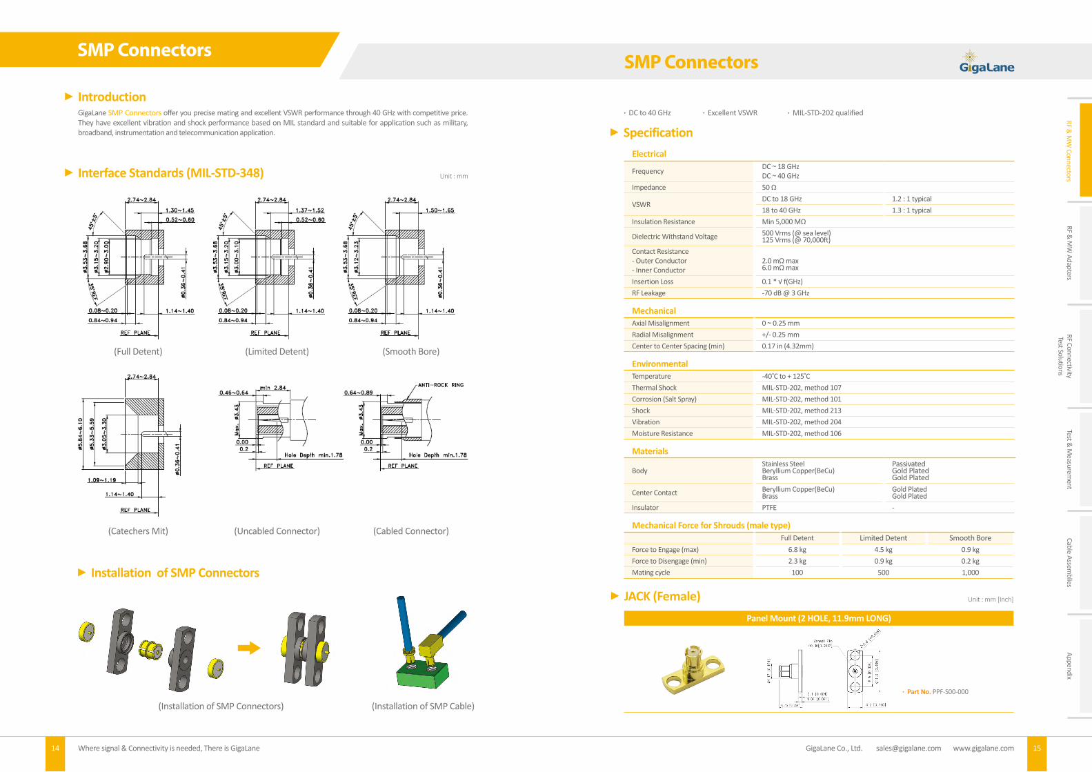
GigaLane SMP Connectors offer you precise mating and excellent VSWR performance through 40 GHz with competitive price. They have excellent vibration and shock performance based on MIL standard and suitable for application such as military, broadband, instrumentation and telecommunication application.
Introduction
Interface Standards (MIL-STD-348) Unit : mm
SpecificationElectrical
Frequency DC ~ 18 GHzDC ~ 40 GHz
Impedance 50 Ω
VSWRDC to 18 GHz 1.2 : 1 typical18 to 40 GHz 1.3 : 1 typical
Insulation Resistance Min 5,000 MΩ
Dielectric Withstand Voltage 500 Vrms (@ sea level) 125 Vrms (@ 70,000ft)
Contact Resistance- Outer Conductor- Inner Conductor
2.0 mΩ max6.0 mΩ max
Insertion Loss 0.1 * √ f(GHz)RF Leakage -70 dB @ 3 GHz
Mechanical Axial Misalignment 0 ~ 0.25 mmRadial Misalignment +/- 0.25 mmCenter to Center Spacing (min) 0.17 in (4.32mm)
EnvironmentalTemperature -40 C to + 125 CThermal Shock MIL-STD-202, method 107Corrosion (Salt Spray) MIL-STD-202, method 101Shock MIL-STD-202, method 213Vibration MIL-STD-202, method 204Moisture Resistance MIL-STD-202, method 106
Materials
BodyStainless SteelBeryllium Copper(BeCu)Brass
PassivatedGold PlatedGold Plated
Center Contact Beryllium Copper(BeCu)Brass
Gold PlatedGold Plated
Insulator PTFE -
Mechanical Force for Shrouds (male type)Full Detent Limited Detent Smooth Bore
Force to Engage (max) 6.8 kg 4.5 kg 0.9 kgForce to Disengage (min) 2.3 kg 0.9 kg 0.2 kgMating cycle 100 500 1,000
DC to 40 GHz Excellent VSWR MIL-STD-202 qualified
Installation of SMP Connectors
Panel Mount (2 HOLE, 11.9mm LONG)
Part No. PPF-S00-000
JACK (Female) Unit : mm [Inch]
(Installation of SMP Connectors) (Installation of SMP Cable)

GigaLane Co., Ltd. [email protected] www.gigalane.com16 17Where signal & Connectivity is needed, There is GigaLane
RF & M
W Connectors
RF & M
W Adapters
RF ConnectivityTest Solutions
Test & M
easurement
Cable Assemblies
Appendix
SMP Connectors
GigaLane BMA Connectors offer you precise mating and excellent VSWR performance through 18 GHz. They are designed based on MIL standard and are ideally suited for communication base station equipment, rack-and-panel applications with appropriate float-mounted jacks, building block systems such as radar.
Introduction
(Jack) (Plug)
SpecificationElectricalFrequency DC to 18 GHz
Impedance 50 Ω
VSWR 1.3 : 1 typical
Insulation Resistance 5000 MΩ
Dielectric Withstand Voltage 1000 Vrms max
Contact resistance- Outer Conductor- Inner Conductor
2mΩ max3mΩ max
Insertion Loss 0.3dB max (@ 18 GHz)
RF Leakage -90 dB @ 18 GHz
Mechanical Mating Cycle(Durability) 1000
Engagement Force 1.5 kg max (14.7 N)
Disengagement Force 0.2 kg min (1.9 N)
EnvironmentalTemperature -40 C to + 125 C
Thermal Shock MIL-STD-202, method 107
Corrosion (Salt Spray) MIL-STD-202, method 101
Shock MIL-STD-202, method 213
Vibration MIL-STD-202, method 204
Moisture resistance MIL-STD-202, method 106
Materials
BodyBeryllium Copper(BeCu)BrassStainless Steel
PassivatedGold PlatedPassivated
Center Contact Beryllium Copper(BeCu)Brass
Gold PlatedGold Plated
Insulator PTFE -
Interface Standards (MIL-STD-348) Unit : mm
BMA Connectors
Unit : mm [Inch]
PCB Thread-in PCB Edge Mount
Type. Part No. Full PPM-S02-F00 Limited PPM-S02-L00 Smooth PPM-S02-S00
Type. Part No. Full PPM-S03-F00Limited PPM-S03-L00Smooth PPM-S03-S00
PCB Right Angle Mount Panel Shroud, Thread-in (No Center Contact)
Type. Part No. Full PPM-R00-F00 Limited PPM-R00-L00 Smooth PPM-R00-S00
Type. Part No. Full PPM-S02-F01Limited PPM-S02-L01Smooth PPM-S02-S01
PPM-S03-F00
5.1 [0.201]
2.3 [0.091]∅4.3
6 [0
.172
]
∅0.84 [0.033]
0.36
[0.
014]
2 [0
.079
]
4.05 [0.159]
6.36 [0.250]
Radial Mis-Alignment Condition Axial Mis-Alignment Condition
Straight JACK (SR085, SF085) Right Angle JACK (SR085, SF085)
Part No. PFS01, PFS02 (18GHZ, 40GHZ) Part No. PFR01
Test Result of SMP Connectors
SMP Connectors for Cable Assemblies Unit : mm [Inch]
4 [0.157]
4.5
5 [
0.1
79]
6.2
5 [
0.2
46]
6.9 [0.272]
-E.J KIM
PFR01
2016. 04. 01
H.W SONG
K.H JUNG
SMP Female RightAngle Connector
for Cable 085
NOTES
1. MATERIAL
1-1. BOBY : BeCu (GOLD PLATED) 1-2. CENTER CONDUCTOR : BeCu (GOLD PLATED) 1-3. INSULATOR : PTFE
2. ELECTRICAL
2-1. IMPEDANCE : 50Ω 2-2. FREQUENCY RANGE : DC to 40GHz 2-3. VSWR(dB) : DC to 18GHz : 1.45 : 1(-15dB)
NS 1 OF 1
mm
REVISIONDESCRIOTION DATE APP.NO DRAWN
www.gigalane.com
Excellence & Innovationin
RF and Microwave GENERAL ANGLES
0 ±0.2 ±2.0°
0.X ±0.1 ±1.0° REV.
This drawing and any data contained herein is the property of Gigalane Co., Ltd. Data is intended for informational propose only.
DATE: TITLE:
UNITS:
TOLERANCE:
ANGLE:
3rd
ANGLE
APPROVED
CHECKED
DRAWN
PRODUCT NO:
SCALE: SHEET :
SMP(F)
PFS01
∅4.25 [0.167]
6.4 [0.252]
0.1 0.2
SMP_Radial
REFERENCE
0.2mm
0.1mm
SMP_Axial
PPM-S02-F00∅5
.5 [
0.21
7]
∅0.8
4 [0
.033
]
3.15 [0.124]
2-1.
1T C
ut [
0.04
3]
M5.0 P0.8
1.5 [0.059] 8.5 [0.335]
PPM-R00-F00
∅4.1
[0.
161]
0.7 [0.028]
6 [0.236] 0.5 [0.020]
6
[0.2
36]
2 [0
.079
]
∅4 [0.157]
PPF-S02-F01
10-48 UNS-2A-THD
1.65 [0.065]
3.05 [0.120]
0.8 [0.031]
2 HOLE Panel Shroud (No Center Contact)
Type. Part No. Full PPM-S00-F00 Limited PPM-S00-L00 Smooth PPM-S00-S00
PPM-S00-F00
0.1 [0.004]
1.13 [0.044]
3.04 [0.120] ∅4.17 [0.164]
8.6 [0.339]
∅12.2 [0.480]
4.2 [0.165]
2-2.6 [0.102]
Frequency [GHz]
VSW
R
1.6
1.5
1.4
1.3
1.2
1.1
10 10 20 30 40
SMP(M) to 2.92mm(F) Adapter
- Measurement Data- Radial Misalignment 0.1- Radial Misalignment 0.2
Frequency [GHz]
VSW
R
1.6
1.5
1.4
1.3
1.2
1.1
10 10 20 30 40
SMP(M) to 2.92mm(F) Adapter
- Measurement Data- Radial Misalignment 0.1- Axial Misalignment 0.2
PLUG (Male)

GigaLane Co., Ltd. [email protected] www.gigalane.com18 19Where signal & Connectivity is needed, There is GigaLane
RF & M
W Connectors
RF & M
W Adapters
RF ConnectivityTest Solutions
Test & M
easurement
Cable Assemblies
Appendix
BMA ConnectorsHigh Performance End Launch Connectors
GigaLane High Performance End Launch Connectors are designed for 2.4mm (50 GHz), 2.92mm (40 GHz) and SMA (27 GHz) with Low VSWR. It is easily connected to GPCW transmission Line and Microstrip Line.
Introduction
SpecificationElectrical
Frequency
2.4 mm DC ~ 50 GHz
2.92 mm DC ~ 40 GHz
SMA DC ~ 27 GHz
Impedance 50 Ω
VSWR 1.57:1 (-13dB)
Insulation loss Low Insertion Loss
EnvironmentalThermal Shock MIL-STD-202, method 107
Corrosion (Salt Spray) MIL-STD-202, method 101
Shock MIL-STD-202, method 213
Vibration MIL-STD-202, method 204
Moisture Resistance MIL-STD-202, method 106
Materials
Connector
Body Stainless Steel Passivated
Center Contact Beryllium Copper(BeCu) Gold Plated
Insulator Engineering Plastic -
Launched Block
Launched Block Brass Ni plated
Pin Beryllium Copper(BeCu) Gold Plated
Insulator PTFE -
Straight PLUG Bulkhead (SR085, SF085) Straight PLUG Bulkhead (SR141, SF141)
Part No. MMS01 Part No. MMS02
Straight Aligner JACK (SR085, SF085) Right Angle JACK (2 HOLE, 21.9mm LONG) (SR141, SF141)
Part No. MFS01 Part No. G05RFC001
Straight Flange Jack (2HOLE, 15.1mm Long)(SR141,SF141)
Part No. G05SFC012
DC to 18 GHz High Reliability & Ease of Assembly Push-On, Non-Locking Type
Test Result of BMA Connectors
PLUG (Male) Unit : mm [Inch]
BMA Connectors for Cable Assemblies Unit : mm [Inch]
Panel Mount (2 HOLE, 15.9mm LONG) Panel Mount (4 HOLE, 12.8mm SQUARE)
Part No. PMM-S00-000 Part No. PMM-S01-000
PMM-S00-000
1.5 [0.059]
3.2 [0.126]
1.65 [0.065]
11 [0.433]∅0
.5 [0.020]
∅2.16 [0.085]
12.2 [0.480]
∅15.9 [0.626]
5.7 [0.224]
2-2.6 [0.102]
PMM-S01-000
1.6 [0.063]
3.2 [0.126]
1.65 [0.065]
11 [0.433]
∅0.5 [0.020]
∅2.16 [0.085]
8.8 [0.346]
12.8 [0.504]
4-2.6 [0.102]
MMS01
Hex 11 [0.433]
Nut(Hex)
8 [0.315]
Washer 1/4"-36 UNS-2A
3.2 [0.126] Max Panel
1.7 [0.067]
17.6 [0.693]
13.1 [0.516]
MMS02
Hex 11 [0.433]
Nut(Hex)
8 [0.315]
Washer 1/4"-36 UNS-2A
1.7 [0.067]
13.1 [0.516]
17.6 [0.693]
3.2 [0.126] Max Panel
MFS01
Nut(H-Cut)
8.9 [0.350]
Washer
11 [0.433] 8/25"-72 UNS-2A
2.9 [0.114] Max Panel
8.55 [0.337]
15.3 [0.602]
18 [0.709]
∅9.5 [0.374]
∅9.45 [0.372]
--
BMA(F)-2Hole PLConn.
NO. Part Name DESCRIPTION Part NO. QTY NOTES
①
②
③
④
SCALE:
NS
APPROVED
CHECK
DRAWNSHEET/OF
1/1
Product NO:
3rdANGLE
mm
ANGLE:
TOLEARANCE:
UNIT:
DATE:
REVISIONDESCRIOTION DATE APPROVEDNO DRAWN
www.gigalane.com
Excellence & Innovationin
RF and Microwave
TITLE:
GENERAL ANGLES
0 ±0.2 ±2.0°
0.X ±0.1 ±1.0° Rev.
This drawing and any data contained herein is the property of Gigalane Co., Ltd. Data is intended for informational propose only.
BODY 1 BRASS / Ni PLATE - 1 -
BODY 2 BRASS / Au PLATE - 1 -
PIN BeCu / Au PLATE - 1 -
- - - 1 -
- - - - -⑤NOTES
1. ELECTRICAL 1-1. Impedance : 50Ω 1-2. Frequency : DC to 6GHz 1-3. VSWR(dB) : Less than TBD @ 6GHz 1-4. Withstanding Voltage : 750Vrms , 1sec, 60Hz
2. ENVIRONMENT
2-1. RoHS : Applied
2-∅3.2
16.0
∅21.9
13 2
9.7 15.1
5.17±0.3 1.6
G05RFC001
16 [0.630]
∅21.9 [0.862]
9.7 [0.382]
2-3.2 [0.126]
21 [0.827]
5.3 [0.209]
1.6 [0.063]
13.9 [0.547]
9.5 [0.374]
∅11.2 [0.441]
Radial Mis-Alignment Condition Axial Mis-Alignment ConditionBMA(M) to SMA(F) Adapter
Frequency [GHz]
1.6
1.5
1.4
1.3
1.2
1.1
1
- Measurement Data- Radial Misalignment 0.25
0 3 6 9 12 15 18
VSW
R
BMA(M) to SMA(F) Adapter
Frequency [GHz]
- Measurement Data- Axial Misalignment 0.4
VSW
R
1.6
1.5
1.4
1.3
1.2
1.1
10 3 6 9 12 15 18

GigaLane Co., Ltd. [email protected] www.gigalane.com20 21Where signal & Connectivity is needed, There is GigaLane
RF & M
W Connectors
RF & M
W Adapters
RF ConnectivityTest Solutions
Test & M
easurement
Cable Assemblies
Appendix
High Performance End Launch Connectors
Mount the end launch connector on the board in the desired position. Make sure the launch pin is at the center of the trace. Make sure the launched block is tight against board. Tighten the M1.6(1.5mm) mounting screws to be tighten unit the connector is secured.
GCPWG Test Result of G01SFB001
Drawing
Installation Procedure
Microstrip with Top Ground Test Result of G01SFB001
VNA
DUT
25.4mm[1.0inch]
Frequency [GHz]
50
40
30
20
10
0
-10
-20
-30
-40
-501.0 5.9 10.8 15.7 20.6 25.5 30.4 35.3 40.2 45.3 50.0
Frequency [GHz]
50
40
30
20
10
0
-10
-20
-30
-40
-501.0 5.9 10.8 15.7 20.6 25.5 30.4 35.3 40.2 45.3 50.0
* PCB : 8 MIL R4003
* PCB : 8 MIL R4003
Specificaton Test Result
- Insertion Loss : Min. -4.2 dB @ 0.1~50 GHz- Return Loss : Max. -13 dB @ 0.1~50 GHz
- Insertion Loss : Min. -3.8 dB @ 0.1~50 GHz- Return Loss : Max. -14.5 dB @ 0.1~50 GHz
Specificaton Test Result- Insertion Loss : Min. -4.2 dB @ 0.1~50 GHz- Return Loss : Max. -13 dB @ 0.1~50 GHz
- Insertion Loss : Min. -3.3 dB @ 0.1~50 GHz- Return Loss : Max. -13.5 dB @ 0.1~50 GHz
Part No. Pin Diameter Dielectric Diameter
A B CG01SFB001
(2.4 mm, 50 GHz) 0.13 [0.005] 0.23 [0.009] 0.73 [0.029]
G02SFB002(2.92 mm, 40 GHz) 0.18 [0.007] 0.3 [0.011] 0.93 [0.036]
G06SFB102(SMA, 27 GHz) 0.18 [0.007] 0.3 [0.011] 0.93 [0.036]
2.4mm / 2.92mm / SMA
Tight Against Board
0.51mm Overhang
High Performance End Launch Connectors
Unit : mm [Inch]
VNA
DUT
25.4mm[1.0inch]

GigaLane Co., Ltd. [email protected] www.gigalane.com22 23Where signal & Connectivity is needed, There is GigaLane
RF & M
W Connectors
RF & M
W Adapters
RF ConnectivityTest Solutions
Test & M
easurement
Cable Assemblies
Appendix
High Performance End Launch ConnectorsHigh Performance End Launch Connectors
GCPWG Test Result of G02SFB002 GCPWG Test Result of G06SFB102
Microstrip with Top Ground Test Result of G02SFB002 Microstrip with Top Ground Test Result of G06SFB102
* PCB : 8 MIL R4003(0.5oz) * PCB : 8 MIL R4003(0.5oz)
* PCB : 8 MIL R4003(0.5oz) * PCB : 8 MIL R4003(0.5oz)
Specificaton Test Result
- Insertion Loss : Min -3.7dB @ 0.1~40GHz- Return Loss : Max. -13dB @ 0.1~40GHz
- Insertion Loss : Min -3.3dB @ 0.1~40GHz- Return Loss : Max. -14.9dB @ 0.1~40GHz
Specificaton Test Result
- Insertion Loss : Min -3.2dB @ 0.1~27GHz- Return Loss : Max. -13dB @ 0.1~27GHz
- Insertion Loss : Min -2.4dB @ 0.1~27GHz- Return Loss : Max. -14.3dB @ 0.1~27GHz
Specificaton Test Result
- Insertion Loss : Min -3.7dB @ 0.1~40GHz- Return Loss : Max. -13dB @ 0.1~40GHz
- Insertion Loss : Min -2.6dB @ 0.1~40GHz- Return Loss : Max. -14.0dB @ 0.1~40GHz
Specificaton Test Result
- Insertion Loss : Min -3.2dB @ 0.1~27GHz- Return Loss : Max. -13dB @ 0.1~27GHz
- Insertion Loss : Min -2.1@ 0.1~27GHz- Return Loss : Max. [email protected]~27GHz
25.4mm[1.0inch] 25.4mm[1.0inch]
25.4mm[1.0inch] 25.4mm[1.0inch]

GigaLane Co., Ltd. [email protected] www.gigalane.com24 25Where signal & Connectivity is needed, There is GigaLane
RF & M
W Connectors
RF & M
W Adapters
RF ConnectivityTest Solutions
Test & M
easurement
Cable Assemblies
Appendix
High Performance End Launch Connectors
GigaLane End Launch SMA Connector is designed for applications such as High Performance RF Circuit Boards. It is attached to RF circuit board by inserting the board edge between legs and soldering legs. It has excellent return Loss up to 26.5 GHz.
7.82 [0.308]
9.47 [0.373]
13.27 [0.522]
A
8 [0.315]
1 [0.040]
3.75 [0.148]
1/4"-36 UNS-2A
PSF-S01-000~011
0.5 [ 0.02
0]
6 [0.236]
1 [0.039]
7.82 [0.308]
9.47 [0.373]
13.27 [0.522]
A
8 [0.315]
1 [0.040]
3.75
[0.
148]
1/4"-36 UNS-2A
PSF-S01-000~011
0.5 [ 0.02
0]
6 [0.236]
1 [0
.039
]
SMA Connector (P/N: PSF-S01-000~011)
Frequency [GHz]
1.6
1.5
1.4
1.3
1.2
1.1
1
- Measurement Data
0 5 10 15 20 25
VSW
R
Part No. Dia A.
PSF-S01-000 0.60 [0.024]
PSF-S01-001 0.80 [0.031]
PSF-S01-002 1.00 [0.039]
PSF-S01-003 1.10 [0.043]
PSF-S01-004 1.20 [0.047]
PSF-S01-005 1.30 [0.051]
PSF-S01-006 1.50 [0.059]
PSF-S01-007 1.60 [0.063]
PSF-S01-008 1.73 [0.068]
PSF-S01-009 2.10 [0.083]
PSF-S01-010 2.25 [0.089]
PSF-S01-011 3.60 [0.142]
* PCB Pattern See Page 90p Fig 2
Unit : mm [Inch]
High Performance End Launch Connectors
GigaLane Quick End Launch (QEL™ SMA) is designed for quick launch at the edge of PCB board up to 18 GHz. Specially designed leg immediately adjusts and firmly holds its attachment with the PCB. It is ideal solution for all active & speedy tests required in R&D. When compared with conventional end launch connector, it will effectually reduce soldering and assembly time when deployed in mass production.
Easy & Speedy insertion Uniquely designed legs maneuvers smoothly and evenly to fit the PCB thickness
Built-in tension of legs enables even and firm attachment to the PCB
Quick End Launch JACK
Part No. Board Clearance PSF-S06-000 0.25 ~ 1.2mm PSF-S06-001 1.25 ~ 2.0mm
<DUT>· Connector - PSF-S06-000 : 2ea
· PCB - FR4 Sub Thickness : 0.6mm - 50 Ω Line Width : 1.2mm - Line Length : 18mm
Unit : mm [Inch]
0.1 [0.004]
5.05 [0.199]
8.5 [0.335]
Hole
0.8 [0.031]
6 [0.236]
8 [0.315]
PSF-S06-000
PSF-S06-001
PSF-S06-000~001
Frequency [GHz]0 3 6 9 12 15 19
0
-10
-20
-30
-40
-50
Retu
rn Lo
ss [d
B]
0.0
-2.0
-4.0
-6.0
-8.0
-10.0
Inse
rtio
n Lo
ss [d
B]
*As described in the table, 2 product specifications are available to accordingly cover all common PCB thicknesses.

GigaLane Co., Ltd. [email protected] www.gigalane.com26 27Where signal & Connectivity is needed, There is GigaLane
RF & M
W Connectors
RF & M
W Adapters
RF ConnectivityTest Solutions
Test & M
easurement
Cable Assemblies
Appendix
High Performance End Launch Connectors
GigaLane VEREND™(Vertical-End launch) SMA Connector is designed for applications such as circuit boards for SMD(Surface Mounted Device) and for vertical mounting on RF test boards. It has excellent electrical transition on right angle section up to 18 GHz.
SMA Connector (P/N: VSF-S00-000)
Frequency [GHz]
1.6
1.5
1.4
1.3
1.2
1.1
1
- Measurement Data
0 5 10 15
VSW
R
4.5 [0.177]
6.5 [0.256]
6.5 [0.256]
8.5 [0.335]
8.5 [0.335]
8.75 [0.344]
15.25 [0.600]
1 [0.039]
2 [0.079]
VSF-S00-000
1/4"-36 UNS-2A
Unit : mm [Inch] JACK (Female) Unit : mm [Inch]
1/4"-36 UNS-2A
12 [0.472]
13 [0.512]
15.25 [0.600]
8.5 [0.335]
6.5
[0.2
56]
8.5
[0.3
35]
0.75
[0.
030]
4.5 [0.177]
6.5 [0.256]
∅0.5 [∅0.0
20]
0.5 [0.020]
VSF-S00-000-001
8.5 [0.335]
6.5 [0.256]
8.5 [0.335]
4.5 [0.177]
6.5 [0.256]9.95 [0.392]
10.95 [0.431]
13.7 [0.539]
14.7 [0.579]
17.45 [0.687]
Nut(Hex)
8 [0.315]
Washer
∅0.5 [∅0.0
20]
1/4"-36 UNS-2A
1.5 [0.059] Max Panel
0.75 [0.030]
VSF-S00-000-004
8.5 [0.335]
6.5 [0.256]
8.5 [0.335]
4.5 [0.177]
6.5 [0.256]
0.5 [0.020]
∅0.5 [∅0.020]
11.9 [0.468]
12.9 [0.508]
13.7 [0.539]
0.75 [0.030]
VSF-S00-000-005
Part No.VSF-S00-000
Part No.VSF-S00-000-001
Part No.VSF-S00-000-005
Part No.VSF-S00-000-004
High Performance SMA Connectors
GigaLane High Performance SMA Connectors are designed for applications up to 26.5 GHz in the common high frequency substrates and it is suitable for military and microwave frequencies.
Introduction
SpecificationElectricalFrequency High performance SMA DC ~ 26.5 GHz
Impedance 50 Ω
VSWR 1.2 : 1 (@ 18 GHz)1.3 : 1 (@ 26.5 GHz)
Insulation Resistance 5000 MΩDielectric Withstand Voltage 1000 Vrms maxContact resistance- Outer Conductor- Inner Conductor
2mΩ max3mΩ max
Insertion Loss 0.4 dB max (@ 26.5 GHz)RF Leakage -90 dB
Power Handling 200 W @ 2 GHz
Mechanical Mating Cycle(Durability) 500
Recommended Mating TorqueProof Torque
0.9 ~ 1.13 Nm / 8 ~ 10 lbs1.7 Nm / 15.0 lbs
Coupling Nut Retention Force 270 N / 27.7 kfg / 61 lbs
Center Contact Retention Force 2.6 pound (axial)
EnvironmentalTemperature -40 C to + 125 CThermal Shock MIL-STD-202, method 107Corrosion (Salt Spray) MIL-STD-202, method 101Shock MIL-STD-202, method 213Vibration MIL-STD-202, method 204
Moisture Resistance MIL-STD-202, method 106
Materials
Body Stainless SteelBrass
PassivatedGold Plated
Center Contact Beryllium Copper(BeCu)Brass
Gold PlatedGold Plated
Insulator PTFE -
Unit : mm [Inch] Interface Standards (MIL-STD-348)
(Jack) (Plug)

GigaLane Co., Ltd. [email protected] www.gigalane.com28 29Where signal & Connectivity is needed, There is GigaLane
RF & M
W Connectors
RF & M
W Adapters
RF ConnectivityTest Solutions
Test & M
easurement
Cable Assemblies
Appendix
DC to 26.5 GHz Mechanically Compatible with 2.92mm & 3.5mm Connectors Suitable for High-speed Wireless application
Panel Mount (4 HOLE, 12.8mm SQUARE) Panel Mount (2 HOLE, 15.9mm LONG)
Part No. PSF-S00-000
Part No. DIM A PSF-S02-000 0.80 [0.03] PSF-S02-001 1.50 [0.06]
Panel Mount Jack (4 HOLE, 12.8mm SQUARE) Panel Mount (2 HOLE, 15.9mm LONG)
Part No. DIM A PSF-S02-003 0.80 [0.03] PSF-S02-004 1.50 [0.06]
Part No. DIM A PSF-S03-000 2.10 [0.08] PSF-S03-001 3.50 [0.14]
Panel Mount Epoxy Captivated (EMI Shielding)
Panel Mount Field Replaceable (EMI Shielding)
JACK (Female) Unit : mm [Inch]
PSF-S00-000
8.8 [0.346]
12.8 [0.504]
1 [0.039]
1.65 [0.065]
9.47 [0.373]
4-2.6 [0.102]
∅0.5
[0.
020]
1/4"-36 UNS-2A 1/4"-36 UNS-2A
A
3.18 [0.125]
1.65 [0.065]
9.47 [0.373]
∅0.4 [0.016]
∅2.1 [0.083]
5.7 [0.224]
15.9 [0.626]
12.2 [0.480]
2-2.7 [0.106]
PSF-S02-000
PSF-S02-003
9.47 [0.373]
1.65 [0.065]
3.18 [0.125]
A
∅0.4 [0.016]
1/4"-36 UNS-2A
4-2.6 [0.102]
8.8 [0.346]
12.8 [0.504]
∅2.1 [0.083]
PSF-S03-000
A
0.5 [0.020]
1.65 [0.065]
9.47 [0.373] 5.7 [0.224]
12.2 [0.480]
15.9 [0.626]
2-2.6 [0.102]
∅0.3 [0.012]
1/4"-36 UNS-2A
∅0.7 [0.028]
PSF-S03-000
A
0.5 [0.020]
1.65 [0.065]
9.47 [0.373] 5.7 [0.224]
12.2 [0.480]
15.9 [0.626]
2-2.6 [0.102]
∅0.3 [0.012]
1/4"-36 UNS-2A
∅0.7 [0.028]
PSF-S03-002~005
1/4"-36 UNS-2A
1.6 [0.063]
0.45 [0.018]
L
1.52 [0.060]
11.1 [0.437]
B A
2-2.6 [0.102]
∅0.3
[0.
012]
∅0.6
5 [0
.026
]
C
PSF-S03-006~013
1/4"-36 UNS-2A
0.05 [0.002]
1.52 [0.060]
11.1 [0.437] C
B A
2-2.6 [0.102]
Accept Pin
Part No. DIM L DIM A DIM B DIM CPSF-S03-002PSF-S03-003PSF-S03-004PSF-S03-005
2.10 [0.080]3.50 [0.140]2.10 [0.080]3.50 [0.140]
14.00 [0.550]14.00 [0.550]16.00 [0.630]16.00 [0.630]
10.20 [0.400]10.20 [0.400]12.20 [0.480]12.20 [0.480]
4.75 [0.190]4.75 [0.190]5.70 [0.220]5.70 [0.220]
Part No. DIM L DIM A DIM B DIM CPSF-S03-006PSF-S03-007PSF-S03-008PSF-S03-009PSF-S03-010PSF-S03-011PSF-S03-012PSF-S03-013
0.30 [0.012]0.38 [0.015]0.46 [0.018]0.51 [0.020]0.30 [0.012]0.38 [0.015]0.46 [0.018]0.51 [0.020]
14.00 [0.55]14.00 [0.55]14.00 [0.55]14.00 [0.55]16.00 [0.63]16.00 [0.63]16.00 [0.63]16.00 [0.63]
10.20 [0.40]10.20 [0.40]10.20 [0.40]10.20 [0.40]12.20 [0.48]12.20 [0.48]12.20 [0.48]12.20 [0.48]
4.75 [0.19]4.75 [0.19]4.75 [0.19]4.75 [0.19]5.70 [0.22]5.70 [0.22]5.70 [0.22]5.70 [0.22]
High Performance SMA ConnectorsSMA Connectors
GigaLane SMA(Sub Miniature A) connectors are widely used in the frequency range DC to 18 GHz with low loss characteristics. SMA connectors are most used in military, microwave frequencies and telecommunication application.
SpecificationElectricalFrequency SMA DC ~ 18 GHz
Impedance 50 Ω
VSWR 1.2 : 1 (@ 6G Hz)1.3 : 1 (@ 18 GHz)
Insulation Resistance 5000 MΩ
Dielectric Withstand Voltage 1000 Vrms max
Contact resistance- Outer Conductor- Inner Conductor
2mΩ max3mΩ max
RF Leakage -90 dB
Power Handling 200 W @ 2 GHz
Mechanical Mating Cycle(Durability) 500
Recommended Mating TorqueProof Torque
0.9 ~ 1.13 Nm / 8 ~ 10 lbs1.7 Nm / 15.0 lbs
Coupling Nut Retention Force 270 N / 27.7 kfg / 61 lbs
Center Contact Retention Force 2.6 pound (axial)
EnvironmentalTemperature -40 C to + 125 C
Thermal Shock MIL-STD-202, method 107
Corrosion (Salt Spray) MIL-STD-202, method 101
Shock MIL-STD-202, method 213
Vibration MIL-STD-202, method 204
Moisture Resistance MIL-STD-202, method 106
MaterialsBody Brass Gold Plated
Center Contact Brass Gold Plated
Insulator PTFE -
Unit : mm [Inch] Interface Standards (MIL-STD-348)
(Jack) (Plug)
Introduction

GigaLane Co., Ltd. [email protected] www.gigalane.com30 31Where signal & Connectivity is needed, There is GigaLane
RF & M
W Connectors
RF & M
W Adapters
RF ConnectivityTest Solutions
Test & M
easurement
Cable Assemblies
Appendix
Right Angle PCB Mount Right Angle Panel Mount (4 HOLE)
Part No. PAF-R00-000
Part No. PAF-R01-000
Right Angle Panel Mount (2 HOLE)
Part No. PAF-R02-000
JACK Right Angle(Female) Unit : mm [Inch]
PAF-R00-000
13.5 [0.531]
4 [0.157]
∅1.2
7 [0
.050
]
1.02 [0.040]
6.
4 [0
.252
]
6.4 [0.252]
14.9
[0.
587]
1/4"-36 UNS-2A
4.5 [0.177]
PAF-R01-000
8.6
[0.3
39]
12
.7 [
0.50
0]
4-2.6 [0.102]
2 [0.079]
5 [0.197]
1.6 [0.063]
11.5 [0.453]
15.0
5 [0
.593
]
8.25 [0.325]
∅1.2
7 [0
.050
]
∅4.1
[0.
161]
1/4"-36 UNS-2A
6.5 [0.256]
* PCB Pattern See Page90p Fig 2
* PCB Pattern See Page 90p Fig 3
* PCB Pattern See Page 90p Fig 3
PAF-R02-000
2 [0.079]
5 [0.197]
1.6 [0.063]
8.25 [0.325]
15.0
5 [0
.593
]
11.5 [0.453]
∅1.2
7 [0
.050
]
∅4.1
[0.
161]
12.2 [0.480]
∅15.9 [0.626]
1/4"-36 UNS-2A
5.7
[0.2
24]
2-2.6 [
0.102]
PAF-R02-000
2 [0.079]
5 [0.197]
1.6 [0.063]
8.25 [0.325]
15.0
5 [0
.593
]
11.5 [0.453]
∅1.2
7 [0
.050
]
∅4.1
[0.
161]
12.2 [0.480]
∅15.9 [0.626]
1/4"-36 UNS-2A
5.7
[0.2
24]
2-2.6 [
0.102]
SMA Connectors
DC to 18 GHz Mechanically Compatible with 2.92mm & 3.5mm Connectors High reliability, Durability and Mechanical stability
Panel Mount with Round Pin (4 HOLE, 12.7mm SQUARE) Panel Mount with Flat Pin (4 HOLE, 12.7mm SQUARE)
Part No. PAF-S00-000
Part No. PAF-S00-001
Panel Mount with Solder Pot Pin (4 HOLE, 12.7mm SQUARE) Panel Mount with Solder Pot Pin (2 HOLE, 15.9mm LONG)
Part No. PAF-S00-002
Part No. PAF-S00-003
PCB Mount (13.5mm LONG) Panel Mount (4 HOLE, 12.7mm SQUARE)
Part No. PAF-S01-000
Part No. PAF-S02-000
End Launch (13.27mm LONG) Panel Mount (2 HOLE, 15.9mm LONG)
Part No. PAF-S06-000
Unit : mm [Inch] JACK (Female) Unit : mm [Inch]
PAF-S00-000
1/4"-36 UNS-2A
1.3 [0.051]
1.7 [0.067]
9.5 [0.374] 12.7 [0.500]
8.6 [0.339]
4-2.6 [0.102]
∅0.5 [0.020]
1/4"-36 UNS-2A
1.7 [0.067]
9.5 [0.374] 12.7 [0.500]
8.6 [0.339]
4-2.6 [0.102]
1.5 [0.059]
0.13 [0.005]
PAF-S00-001
1/4"-36 UNS-2A
1.7 [0.067]
9.5 [0.374] 12.7 [0.500]
8.6 [0.339]
4-2.6 [0.102]
5.15 [0.203]
∅1.27 [0.050]
∅0.8 [0.031]
2.5 [0.098]
PAF-S00-002PAF-S00-003
1/4"-36 UNS-2A
1.7 [0.067]
9.5 [0.374]
5.15 [0.203]
∅1.2
7 [0
.050
]
∅0.8
[0.
031]
2.5 [0.098]
12.2
[0.
480]
∅15.
9 [0
.626
]
5.7 [0.224]
2-2.6 [0.102]
PAF-S01-000
∅1.27 [0.050]
13.5 [0.531]
4 [0.157]
6.3 [0.248]
1.02 [0.040]
1/4"-36 UNS-2A
4.5 [0.177]
PAF-S02-000
2 [0.079]
5 [0.197]
1.7 [0.067]
9.5 [0.374]
8.6 [0.339]
12.7 [0.500]
∅1.27 [0.050]
∅4.1 [0.161]
1/4"-36 UNS-2A
4-2.6 [0.102]
PAF-S05-000~011
1/4"-36 UNS-2A
7.82 [0.308]
9.47 [0.373]
13.27 [0.522]
A
6 [0.236]
8 [0.315]
3.75
[0.
148]
0.5 [ 0.02
0]
3 [0.118]
1 [0
.039
]
2 [0.079]
5 [0.197]
1.7 [0.067]
9.5 [0.374]
∅1.27 [0.050]
∅4.1 [0.161]
1/4"-36 UNS-2A
12.2 [0.480]
∅15.9 [0.626]
5.7 [0.224]
2-2.6 [0.102]
PAF-S06-000
* PCB Pattern See Page 90p Fig 4
Part No. DIM APAF-S05-000PAF-S05-001PAF-S05-002PAF-S05-003PAF-S05-004PAF-S05-005PAF-S05-006PAF-S05-007PAF-S05-008PAF-S05-009PAF-S05-010PAF-S05-011
0.60 [0.024]0.80 [0.031]1.00 [0.039]1.10 [0.043]1.20 [0.047]1.30 [0.051]1.50 [0.059]1.60 [0.063]1.73 [0.068]2.10 [0.083]2.25 [0.089]3.60 [0.142]
* PCB Pattern See Page 90p Fig 4
* PCB Pattern See Page 90p Fig 3
Straight PLUG(Male) Right Angle PLUG(Male)
Bulkhead JACK(Female), 11mm HEX Bulkhead JACK(Female), 8.0mm HEX
Straight JACK(Female) Panel Mount JACK (2 HOLE, 15.9mm LONG)
Panel Mount JACK (4 HOLE, 12.7mm SQUARE)
AFS01
2.2 [0.087]
13.6 [0.535]
16.7 [0.657]
3.0 [0.118] Max Panel
Nut(Hex)
8 [0.315]
Washer 1/4"-36 UNS-2A
5.85 [0.230]
Hex 11 [0.433]
Right Angle PCB Mount Right Angle Panel Mount (4 HOLE)
Bulkhead JACK(Female), 11mm HEX Bulkhead JACK(Female), 8.0mm HEX
Unit : mm [Inch] For Semi-Rigid & Semi-Flexible Cable Assemblies Unit : mm [Inch]
2.2 [0.087]
11.55 [0.455]
Hex-Nut 8 [0.315]
AMS27AMR02
Hex-Nut 8 [0.315]
16.13 [0.635]
6.6 [0.260]
8.6
[0.3
39]
6.45 [0.254]
∅4.6 [0.181]
AFS34
13.2 [0.520]
1.8 [0.071]
16.1 [0.634]
Nut(Hex)
8 [0.315]
Washer
3.0 [0.118] Max Panel
5.85 [0.230]
Hex 8 [0.315]
1/4"-36 UNS-2A
2.35 [0.093]
11.1 [0.437]
14 [0.551] 6 [0.236]
1/4"-36 UNS-2A
AFS20
1.7 [0.067]
9.5 [0.374]
12.7 [0.500]
12.2 [0.480]
∅15.9 [0.626]
2-2.6 [0.102]
1/4"-36 UNS-2A
5.7 [0.224]
AFS04
1.7 [0.067]
9.5 [0.374]
12.7 [0.500]
12.2 [0.480]
∅15.9 [0.626]
2-2.6 [0.102]
1/4"-36 UNS-2A
5.7 [0.224]
AFS04
Cable Part No.047085141
AMS28AMS19AMS23
Cable Part No.085141
AFS01AFS02
Cable Part No.RG316RG178RG400
AMS05AMS06AMS07
Cable Part No.RG316RG178RG400
AFS10AFS11AFS12
Cable Part No.085141
AMR01AMR02
Cable Part No.047085141
AFS04AFS05AFS06
For Flexible Cable Assemblies Unit : mm [Inch]
5.5 [0.217]
15.3 [0.602]
Hex-Nut 8 [0.315]
AMS05
16.13 [0.635] 6.6 [0.260]
Hex-Nut 8 [0.315]
AMR03
8.6 [0.339]
13.6 [0.535]
10.3 [0.406]
AFS01
2.2 [0.087]
13.6 [0.535]
16.7 [0.657]
3.0 [0.118] Max Panel
Nut(Hex)
8 [0.315]
Washer 1/4"-36 UNS-2A
5.85 [0.230]
Hex 11 [0.433]
Nut(Hex)
8 [0.315]
Washer 1/4"-36 UNS-2A
1.7 [0.067]
12.7 [0.500]
18.2 [0.717]
3.0 [0.118] Max Panel
5.85 [0.230]
Hex 8 [0.315]
AFS14
SMA Connectors for Cable Assemblies
9.5 [0.374]
1.7 [0.067]
12.7 [0.500]
8.6 [0.339]
12.7 [0.500]
1/4"-36 UNS-2A4-2.6 [0.102]
AFS07
Cable Part No.047085141
AFS07AFS08AFS09
Cable Part No.085141
AFS34AFS03
Cable Part No.RG316RG178RG400
AMR03AMR04AMR05
Cable Part No.034047085141
AFS20AFS21AFS22AFS36
Cable Part No.RG316RG178RG400
AFS14AFS15AFS16

GigaLane Co., Ltd. [email protected] www.gigalane.com32 33Where signal & Connectivity is needed, There is GigaLane
RF & M
W Connectors
RF & M
W Adapters
RF ConnectivityTest Solutions
Test & M
easurement
Cable Assemblies
Appendix
(Jack) (Plug)
MCX Connectors
GigaLane MCX Connectors are intended for use with microwave application requiring excellent performance up to 6G Hz in 50 Ohm impedance. MCX connectors are similar in design to SMB connectors but smaller than SMB connectors. Typical applications for MCX connectors include GPS, wireless communication and automotives.
Introduction
Specification
Interface Standards (MIL-STD-348)
ElectricalFrequency DC to 6 GHz
Impedance 50 Ω
VSWR 1.2 : 1 to 6 GHz
Insulation Resistance 5000 MΩ
Dielectric Withstand Voltage 750 Vrms max
Contact Resistance- Outer Conductor- Inner Conductor
2mmΩ max6mmΩ max
RF Leakage > 60 dB
Power Handling 50W (@ 2 GHz)
Mechanical Mating Cycle(Durability) 500
Engagement and Separation Force 3.5 kgf max (34.3 N max)
Contact Captivation 1.0 kgf Min. (9.8 N Min)
Mating Torque 6 pound max
Center Contact Retention Force 2.25 pound (axial)
EnvironmentalTemperature -40 C to + 125 C
Thermal Shock CECC22220 4.6.7
Corrosion (Salt Spray) CECC22220 4.6.10
Vibration CECC22220 4.6.3
Moisture Resistance CECC22220 4.6.4
MaterialsBody Brass/Beryllium Copper(BeCu) Gold Plated
Center Contact Brass/Beryllium Copper(BeCu) Gold Plated
Insulator PTFE -
Unit : mm
*Note : These characteristics are typical but may not apply to all connectors.
PCB Mount PCB Mount
PCB Edge Mount Panel Mount (2 HOLE 16mm LONG)
Right Angle PCB Mount Right Angle PCB Mount
Unit : mm [Inch] JACK (Female) Unit : mm [Inch]
Plug(Male) Unit : mm [Inch]
PDF-S01-000
3.75 [0.148]
8.25 [0.325]
6 [0.236]
4.2 [0.165]
2.8 [0.110]
2.5 [0.098]
∅4.9 [0.193]
∅0.95 [0.037]
0.3 [0.012]
PDF-S02-000
∅5 [
0.19
7]
10 [0.394]
4 [0.157]
0.8 [0.031]
6 [0.236]
∅0.95 [0.037]
0.3 [0.012]
PDF-S03-000
4.8 [0.189]
3.05 [0.120]
9.3 [0.366]
2.03
[0.
080]
5 [0
.197
]
6.63 [0.261]
0.95
[0.
037]
PDF-S03-000
4.8 [0.189]
3.05 [0.120]
9.3 [0.366]
2.03
[0.
080]
5 [0
.197
]
6.63 [0.261]
0.95
[0.
037]
PDF-S04-000
∅5 [0.197]
1.3 [0.051]
5 [0.197] 5 [0.197]
13.2 [0.520]
∅6.1 [0.240]
7.5 [0.295]
12.2 [0.480]
16 [0.630]
2-2.6 [0.102]
∅0.95 [0.037]
PDF-R00-000
∅4.8
[0.
189]
3.5 [0.138]
9.5 [0.374]
6 [0
.236
]
8 [0
.315
]
0.2
[0.0
08]
3 [0.118]
4.6 [0.181]
6 [0.236]
∅0.95 [0.037]
PDF-R01-000
∅4.8 [0.189]
3.5 [0.138]
9.5 [0.374]
6 [0.236]
6.4 [0.252]
0.2 [0.008] 3 [0.118]
4.2 [0.165]
6 [0.236]
∅0.95 [0.037]
Straight PLUG Right Angle PLUG
DMS01
4.2 [0.165]
9.4 [0.370]
∅5 [
0.19
7]
11.9 [0.469]
DMR01
8.25 [0.325]
4.2 [0.165]
5 [0.197]
8.6 [0.339]
5 [0.197]
DMR01
8.25 [0.325]
4.2 [0.165]
5 [0.197]
8.6 [0.339]
5 [0.197]
PCB Mount
PDM-S01-000
8.4 [0.331]
2.5 [0.098]
4.5 [0.177] 3.2 [0.126]
4.4 [0.173]
6 [0.236]
∅0.95 [0.037]
0.3 [0.012]
Cable Part No.047085
DMS04DMS01
Cable Part No.047085
DMR05DMR01
Straight PLUG Right Angle PLUG
Cable Part No.RG178RG316
DMS05DMS02
DMR02
10.55 [0.416]
∅3.3 [0.130]
4.2 [0.165]
5 [0.197]
8.6 [0.339]
5 [0.197]
Cable Part No.RG178RG316
DMR04DMR02
DMS02
4.2 [0.165]
9.4 [0.370]
∅5 [
0.19
7]
14.9 [0.587]
Part No.PDM-S01-000* PCB Pattern See Page 90p Fig 5
Part No.PDF-S01-000
Part No.PDF-S02-000
* PCB Pattern See Page 90p Fig 5 * PCB Pattern See Page 90p Fig 5
Part No.PDF-S03-000
Part No.PDF-S04-000
* PCB Pattern See Page 90p Fig 8 * PCB Pattern See Page 90p Fig 9
Part No.PDF-R00-000
Part No.PDF-R01-000
* PCB Pattern See Page 90p Fig 6 * PCB Pattern See Page 90p Fig 7
For Semi-Rigid & Semi-Flexible Cable Assemblies Unit : mm [Inch]
MCX Connectors for Cable Assemblies
For Flexible Cable Assemblies Unit : mm [Inch]
MCX Connectors

GigaLane Co., Ltd. [email protected] www.gigalane.com34 35Where signal & Connectivity is needed, There is GigaLane
RF & M
W Connectors
RF & M
W Adapters
RF ConnectivityTest Solutions
Test & M
easurement
Cable Assemblies
Appendix
GigaLane MMCX Connectors are intended for use in applications where the smallest dimensions are required. These connectors operate up to 6 GHz and are optimum for wireless communication systems such as cellular, wireless and PCS. MMCX provides a low RF-leakage by its non-slotted outer contract.
Introduction
Specification
Interface Standards (MIL-STD-348)
(Jack) (Plug)
Unit : mm
ElectricalFrequency DC to 6 GHz
Impedance 50 Ω
VSWR 1.3 : 1 to 6 GHz
Insulation Resistance 1000 MΩ
Dielectric Withstand Voltage 250 Vrms max
Contact Resistance- Outer Conductor- Inner Conductor
2mΩ max6mΩ max
RF Leakage > 50 dB@ 3 GHz
Power Handling 50W (@ 2 GHz)
Mechanical Mating Cycle(Durability) 500
Engagement and Separation Force 3.5 kgf max (34.3N max)
Center Contact Retention Force 2.25 pound (axial)
EnvironmentalTemperature -40 C to + 125 C
Thermal Shock CECC22220 4.6.7
Corrosion (Salt Spray) CECC22220 4.6.10
Vibration CECC22220 4.6.3
Moisture Resistance CECC22220 4.6.4
MaterialsBody Brass/Beryllium Copper(BeCu) Gold Plated
Center Contact Brass/Beryllium Copper(BeCu) Gold Plated
Insulator PTFE -
MMCX Connectors
Unit : mm [Inch] JACK (Female)PCB Mount PCB Mount
PCB Edge Mount Right Angle PCB Mount
PEF-S00-000
5 [0.197]
∅3.4 [0.134]
3.4 [0.134]
1.85 [0.073]
3.45 [0.136]
∅0.7 [
0.028]
0.75 [0.030]
PEF-S01-000
3 [0.118]
6.5 [0.256]
4.5 [0.177]
∅3.3 [0.130]
3.45 [0.136]
1.85 [0.073]
∅0.7 [
0.028]
Part No.PEF-S00-000
Part No.PEF-S01-000
* PCB Pattern See Page 90p Fig 10 * PCB Pattern See Page 90p Fig 11
PEF-R00-000
6.5 [0.256]
∅3.45 [0.136]
6.5 [0.256]
0.3 [0.012]
4.3 [0.169]
2.04 [0.080]
3.5 [0.138]
∅0.7 [
0.028]
PEF-R00-000
6.5 [0.256]
∅3.45 [0.136]
6.5 [0.256]
0.3 [0.012]
4.3 [0.169]
2.04 [0.080]
3.5 [0.138]
∅0.7 [
0.028]
PEF-S02-000
4.45 [0.175]
5.45 [0.215]
3.5
[0.1
38] ∅0.7 [
0.028]
3.4 [0.134]
4.5 [0.177]
0.7
[0.0
28]
1.4
[0.0
55]
PEF-S02-000
4.45 [0.175]
5.45 [0.215]
3.5
[0.1
38] ∅0.7 [
0.028]
3.4 [0.134]
4.5 [0.177]
0.7
[0.0
28]
1.4
[0.0
55]
Part No.PEF-S02-000* PCB Pattern See Page 90p Fig 13
Part No.PEF-R00-000* PCB Pattern See Page 90p Fig 12
Straight PLUG Right Angle PLUG
Straight JACK Bulkhead JACK
Cable Part No.RG178RG316
EFS01EFS03
Cable Part No.RG178RG316
EMR04EMR01
EMS01
13.2 [0.520]
8.2 [0.323]
3.8
[0.1
50]
EFS01∅3
.8 [
0.15
0]
8 [0.315]
12 [0.472]
EMR01
9 [0.354]
3.5 [0.138]
6.95 [0.274]
∅2.35 [0.093]
4.5 [0.177]
EFS02
18.2 [0.717]
10 [0.394] 7.2 [0.283]
∅4.8
3 [0
.190
]
∅6.5
[0.
256]
Nut(Hex)
6 [0.236]
10-56 UNS-2A
Cable Part No.RG178RG316
EMS04EMS01
Cable Part No.RG178RG316
EFS04EFS02
For Semi-Rigid & Semi-Flexible Cable Assemblies
For Flexible Cable Assemblies Unit : mm [Inch]
Straight PLUG Right Angle PLUG
Cable Part No.047085
EMS03EMS02
Cable Part No.047085
EMR02EMR03
EMS02
11.2 [0.441]
8.2 [0.323]∅2.3
5 [0
.093
]
EMR02
9 [0.354]
3.5 [0.138]
6.95 [0.274]
∅2.35 [0.093]
5.5 [0.217]
Unit : mm [Inch]
MMCX Connectors for Cable Assemblies
MMCX Connectors

GigaLane Co., Ltd. [email protected] www.gigalane.com36 37Where signal & Connectivity is needed, There is GigaLane
RF & M
W Connectors
RF & M
W Adapters
RF ConnectivityTest Solutions
Test & M
easurement
Cable Assemblies
Appendix
GigaLane N-type connectors are designed for applications up to 11 GHzBecause of the endurance, it is optimum for high power fixed wireless communication equipments.
Introduction
Specification(Jack) (Plug)
Interface Standards (MIL-STD-348) Unit : mm
ElectricalFrequency DC ~ 11 GHz
Impedance 50 Ω
VSWR 1.2 : 1 to 11 GHz
Insulation Resistance 5000 MΩ
Dielectric Withstand Voltage 1200 Vrms max
Contact Resistance- Outer Conductor- Inner Conductor
1mΩ max1mΩ max
Insertion Loss 0.2 dB max @ 11 GHz
RF Leakage > 60 dB
Power Handling 500W (@ 2 GHz)
Mechanical Mating Cycle(Durability) 500
Recommended Mating TorqueProof Torque
0.68 ~ 1.33 Nm / 5 ~ 12 lbs1.73 Nm / 15.0 lbs
Coupling Nut Retention Force 45.8 kgf (450N)
Contact Captivation 2.8 kgf Min. (28N Min.)
EnvironmentalTemperature -40 C to + 125 C
Thermal Shock MIL-STD-202, method 107, test condition B
Corrosion (Salt Spray) MIL-STD-202, method 101, test condition B, 5% salt
Vibration MIL-STD-202, method 204, condition B (20G)
Shock MIL-STD-202, method 213, condition I (100G)
Moisture Resistance MIL-STD-202, method 106
MaterialsBody Brass Ni Plated
Center contact Beryllium Copper(BeCu)Brass
Gold PlatedGold Plated
Insulator PTFE -
Gaskets Silicon -
N-Type Connectors
Panel Mount (4 HOLE, 25.4mm SQUARE) Panel Mount (4 HOLE, 17.5mm SQUARE)
Bulkhead Mount Bulkhead Mount (4 HOLE, 25.4mm SQUARE)
PNF-S02-000
5/8"-24 UNEF-2A
∅13.
5 [0
.531
]
22.5 [0.886]
25.7 [1.012]
Nut(Hex)
19 [0.748]
13.25 [0.522]
∅3.02 [0.119]
∅21
[0.8
27]
4 [0.157]
3 [0.118]
PNF-S02-000
5/8"-24 UNEF-2A
∅13.
5 [0
.531
]
22.5 [0.886]
25.7 [1.012]
Nut(Hex)
19 [0.748]
13.25 [0.522]
∅3.02 [0.119]
∅21
[0.8
27]
4 [0.157]
3 [0.118]
Straight PLUG Bulk head PLUG
Panel Mount (4 HOLE, 25.4mm SQUARE)
Unit : mm [Inch] JACK (Female) Unit : mm [Inch]
3 [0.118]
3.2 [0.126]
25.4 [1.000]
18.2 [0.717]
∅13.5 [0.531]
16.7 [0.657]
18.7 [0.736]
5/8"-24 UNEF-2A
PNF-S00-000
5 [0.197]
3 [0.118]
3 [0.118]
3.2 [0.126]
25.4 [1.000]
18.2 [0.717]
∅13.5 [0.531]
16.7 [0.657]
18.7 [0.736]
5/8"-24 UNEF-2A
PNF-S00-000
5 [0.197]
3 [0.118]
3 [0.118]
3.2 [0.126]
17.5 [0.689]
12.7 [0.500]
∅13.5 [0.531]
16.7 [0.657]
18.7 [0.736]
5/8"-24 UNEF-2A
PNF-S01-000
5 [0.197]
2 [0.079]
3 [0.118]
3.2 [0.126]
17.5 [0.689]
12.7 [0.500]
∅13.5 [0.531]
16.7 [0.657]
18.7 [0.736]
5/8"-24 UNEF-2A
PNF-S01-000
5 [0.197]
2 [0.079]
PNF-S03-000
18.2 [0.717]
25.4 [1.000]
13.2 [0.520]
3 [0.118]
3.3 [0.130]
5/8"-24 UNEF-2A
∅13.6 [0.535]
23 [0.906]
25.2 [0.992]
Nut(Hex)
19 [0.748]
4 [0.157]
3 [0.118]
Cable Part No.047085141
NMS01NMS31NMS17
Cable Part No.085141
NFS01NFS02
Cable Part No.085141
NFS09NFS03
NMS01
23 [0.906]
20.5 [0.807]
∅19.4 [0.764]
Cross Knurl
∅20.5 [0.807]
NFS03
3.2 [0.126]
3 [0.118]
∅13.
5 [0
.531
]
18.2 [0.717]
25.4 [1.000]
16.7 [0.657]
18.7 [0.736]
5/8"-24 UNEF-2A
3.5 [0.138]
2.5 [0.098]
NFS03
3.2 [0.126]
3 [0.118]
∅13.5 [0.531]
18.2 [0.717]
25.4 [1.000]
16.7 [0.657]
18.7 [0.736]
5/8"-24 UNEF-2A
3.5 [0.138]
2.5 [0.098]
NFS01
13.25 [0.522]
∅3.02 [0.119]
∅13.5 [0.531]
22.5 [0.886]
25.7 [1.012]
∅9.24 [0.364]
∅21 [0.827]
5/8"-24 UNEF-2A
Nut(Hex)
19 [0.748]
1.9 [0.075]
3 [0.118]
NFS01
13.25 [0.522]
∅3.02 [0.119]
∅13.5 [0.531]
22.5 [0.886]
25.7 [1.012]
∅9.24 [0.364]
∅21 [0.827]
5/8"-24 UNEF-2A
Nut(Hex)
19 [0.748]
1.9 [0.075]
3 [0.118]
Panel Mount
Part No.PNF-S04-000
PNF-S04-000
8 [0.315]
19 [0.748]
25 [0.984]
13.9 [0.547]
∅13.
5 [0
.531
]
∅12.
4 [0
.488
]
5/8"-24 UNEF-2A M14 X P1.0
2 [0.079]
PNF-S04-000
8 [0.315]
19 [0.748]
25 [0.984]
13.9 [0.547]
∅13.
5 [0
.531
]
∅12.
4 [0
.488
]
5/8"-24 UNEF-2A M14 X P1.0
2 [0.079]
For Flexible Cable Assemblies Unit : mm [Inch]
Straight PLUG
Cable Part No.RG316RG400
NMS22NMS04
NMS04
∅19.4 [0.764]
22 [0.866]
30 [1.181]
Cross Knurl
∅20.5 [0.807]
Part No.PNF-S01-000* PCB Pattern See Page 90p Fig 15
Part No.PNF-S03-000* PCB Pattern See Page 90p Fig 16
Part No.PNF-S00-000* PCB Pattern See Page 90p Fig 15
For Semi-Rigid & Semi-Flexible Cable Assemblies Unit : mm [Inch]
N-Type Connectors for Cable Assemblies
N-Type Connectors
Part No.PNF-S02-000* PCB Pattern See Page 90p Fig 15
38 Where signal & Connectivity is needed, There is GigaLane
RF & M
W Connectors
RF & M
W Adapters
RF ConnectivityTest Solutions
Test & M
easurement
Cable Assemblies
Appendix
GigaLane Co., Ltd. [email protected] www.gigalane.com 39
RF & MW Adapters- Precision Adapters in Series- Precision Adapters between Series- SMP Adapters- BMA Adapters- Standard Adapters

RF & M
W Connectors
RF & M
W Adapters
RF ConnectivityTest Solutions
Test & M
easurement
Cable Assemblies
Appendix
GigaLane Co., Ltd. [email protected] www.gigalane.com 41
Precision Adapters in Series
40 Where signal & Connectivity is needed, There is GigaLane
Precision Adapters in Series
2.4mm to 2.4mm 2.92mm to 2.92mm
ElectricalFrequency DC to 50 GHz
Insertion Loss IL[dB] = max 0.06 x √F
Impedance 50Ω
VSWR 1.2:1 max
Temperature -40˚C to + 125˚C
MaterialsBody Stainless Steel Passivated
Center Contact Beryllium Copper(BeCu) Gold Plated
Insulator Engineering Plastic -
ElectricalFrequency DC to 40 GHz
Insertion Loss IL[dB] = max 0.06 x √F
VSWR 4 ~ 40 GHz 1.2 : 1 max
Temperature -40˚C to + 125˚C
MaterialsBody Stainless steel Passivated
Center Contact Beryllium Copper(BeCu) / Brass Gold Plated
Insulator Engineering Plastic -
2.4 mm (M) - 2.4 mm (M) 2.4 mm (M) - 2.4 mm (F)
Part No. 2MS-ADP-2MS-01 Freq. 50 GHz VSWR Max. 1.25
Part No. 2MS-ADP-2FS-01 Freq. 50 GHz VSWR Max. 1.25
2.4 mm (F) - 2.4 mm (F)
Part No. 2FS-ADP-2FS-01 Freq. 50 GHz VSWR Max. 1.25
2.92 mm (M) - 2.92 mm (M) 2.92 mm (M) - 2.92 mm (F)
Part No. KMS-ADP-KMS-01 Freq. 40 GHz VSWR Max. 1.2
Part No. KMS-ADP-KFS-01 Freq. 40 GHz VSWR Max. 1.2
2.92 mm (F) - 2.92 mm (F) 2.92 mm (F) - 2.92 mm (F) (4 HOLE, 12.7mm SQUARE)
Part No. KFS-ADP-KFS-01 Freq. 40 GHz VSWR Max. 1.2
Part No. KFS-ADP-KFS-03-4H Freq. 40 GHz VSWR Max. 1.2
Unit : mm [Inch]
Unit : mm [Inch]
2MS-ADP-2MS-01
17.85 [0.703]
Hex-Nut 8 [0.315]
2.4(M)
Hex-Nut 8 [0.315]
2.4(M)
18.75 [0.738]
2.4(M)
Hex-Nut 8 [0.315] 1/4"-36 UNS-2A
2.4(F)
2MS-ADP-2FS-01
Hex 7.9 [0.311]
11.15 [0.439]
1.5 [0.059]
Hex 7.9 [0.311]
2.4(F)
M7.0 P0.75 M7.0 P0.75
2.4(F)
2FS-ADP-2FS-01
19.6 [0.772]
10.8 [0.425]
2 [0.079]
2.4mm(M) to 2.4mm(M) (P/N: 2MS-ADP-2MS-01)
2.92mm(M) to 2.92mm(M) (P/N: KMS-ADP-KMS-01)
Frequency [GHz]
Frequency [GHz]
VSW
R
VSW
R1.6
1.6
1.5
1.5
1.4
1.4
1.3
1.3
1.2
1.2
1.1
1.1
1
1
0
0
10
10
20
20
30 40
30
50
40
18.8 [0.740]
Hex-Nut 8 [0.315] Hex-Nut 8 [0.315]
2.92(M) 2.92(M)
KMS-ADP-KMS-01
Hex-Nut 8 [0.315] 1/4"-36 UNS-2A
17.6 [0.693]
2.92(M) 2.92(F)
KMS-ADP-KFS-01
Hex 7.9 [0.311]
1.5 [0.059]
11.1 [0.437]
16.4 [0.646]
1/4"-36 UNS-2A
2.92(F)2.92(F)
1/4"-36 UNS-2A
KFS-ADP-KFS-01
Hex 7.9 [0.311]
2 [0.079]
9.2 [0.362]22.2 [0.874]
9.5 [0.374]
1.6 [0.063]
8.6 [0.339]
12.7 [0.500]
4-2.6 [0.102]
2.92(F)
1/4"-36 UNS-2A 1/4"-36 UNS-2A
2.92(F)
KFS-ADP-KFS-03-4H
2.92 mm (F) - 2.92 mm (F)
Part No. KFS-ADP-KFS-02-BH Freq. 40 GHz VSWR Max. 1.2
2.92(F)
1/4"-36 UNS-2A
2.92(F)
Nut(Hex)
8 [0.315]
Washer
15.2 [0.598]
5.2 [0.205] Max Panel
22.2 [0.874]
5.85 [0.230]
Hex 7.9 [0.311]
1/4"-36 UNS-2A
KFS-ADP-KFS-02-BH

RF & M
W Connectors
RF & M
W Adapters
RF ConnectivityTest Solutions
Test & M
easurement
Cable Assemblies
Appendix
GigaLane Co., Ltd. [email protected] www.gigalane.com 43
Precision Adapters in Series
42 Where signal & Connectivity is needed, There is GigaLane
Precision Adapters in Series
SMA (M) - SMA (M) SMA (M) - SMA (F)
Part No. SMS-ADP-SMS-01 Freq. 18 GHz VSWR Max. 1.2
Part No. SMS-ADP-SFS-01 Freq. 18 GHz VSWR Max. 1.2
SMA (F) - SMA (F) SMA (F) - SMA (F) (4 HOLE 12.7mm SQUARE)
Part No. SFS-ADP-SFS-01 Freq. 18 GHz VSWR Max. 1.2
Part No. SFS-ADP-SFS-06-4H Freq. 18 GHz VSWR Max. 1.2
3.5mm to 3.5mm SMA to SMA
ElectricalFrequency DC to 26.5 GHz
Insertion Loss IL[dB] = max 0.06 x √F
VSWR 1.2 : 1 max
Temperature -40˚C to + 125˚C
MaterialsBody Stainless Steel Gold Plated
Center Contact Beryllium Copper(BeCu) / Brass Gold Plated
Insulator Engineering Plastic -
ElectricalFrequency DC to 18 GHz
Insertion Loss IL[dB] = max 0.06 x √F
VSWR 1.2 : 1 max
Temperature -40˚C to + 125˚C
MaterialsBody Stainless steel Passivated
Center Contact Beryllium Copper(BeCu) / Brass Gold Plated
Insulator PTFE -
3.5 mm (M) - 3.5 mm (M) 3.5 mm (M) - 3.5 mm (F)
Part No. 3MS-ADP-3MS-01 Freq. 26.5 GHz VSWR Max. 1.2
Part No. 3MS-ADP-3FS-01 Freq. 26.5 GHz VSWR Max. 1.2
3.5 mm (F) - 3.5 mm (F)
Part No. 3FS-ADP-3FS-01 Freq. 26.5 GHz VSWR Max. 1.2
Unit : mm [Inch]
Unit : mm [Inch]
3.5mm(M) to 3.5mm(M) (P/N: 3MS-ADP-3MS-01)
SMA(M) to SMA(M) (P/N: SMS-ADP-SMS-01)
Frequency [GHz]
Frequency [GHz]
VSW
R
VSW
R
1.6
1.6
1.5
1.5
1.4
1.4
1.3
1.3
1.2
1.2
1.1
1.1
1
1
0
0
5
3 6
10
9 12
15 20
15
25
18
22.1 [0.870]
Hex-Nut 8 [0.315]
SMS(M)
Hex-Nut 8 [0.315]
SMA(M)
Hex 7.9 [0.311]
SMS-ADP-SMS-01
1.5 [0.059]
11.8 [0.465]
21 [0.827]
SMS(M)
Hex-Nut 8 [0.315]
Hex 7.9 [0.311]
SMA(F)
1/4"-36 UNS-2A
12.3 [0.484]
2 [0.079]
SMS-ADP-SFS-01
1.92 [0.076]
11.2 [0.441]
19.9 [0.783]
SMA(F)
1/4"-36 UNS-2A
SMA(F)
1/4"-36 UNS-2A
Hex 7.9 [0.311]
SFS-ADP-SFS-01
1.7 [0.067]1.6 [0.063]
9.5 [0.374]
22.2 [0.874]
8.6 [0.339]
12.7 [0.500]
4-2.6 [0.102]
SMA(F)
1/4"-36 UNS-2A
SMA(F)
1/4"-36 UNS-2A
SFS-ADP-SFS-06-4H
3MS-ADP-3MS-01
14.41 [0.567]
5.1 [0.201]
23.7 [0.933]
Hex-Nut 8 [0.315]
3.5(M)
Hex-Nut 8 [0.315]
3.5(M)
Hex 7.9 [0.311]
13.55 [0.533]
5.1 [0.201]
21.9 [0.862]
3.5(F)
1/4"-36 UNS-2A
3.5(F)
1/4"-36 UNS-2A
Hex 7.9 [0.311]
3FS-ADP-3FS-01
13.49 [0.531]
5.1 [0.201]
22.8 [0.898]
Hex-Nut 8 [0.315]
3.5(M)
Hex 7.9 [0.311]
3.5(F)
1/4"-36 UNS-2A
3MS-ADP-3FS-01
SMA (F)-SMA (F) Bulkhead
Part No. SFS-ADP-SFS-05-BH Freq. 18 GHz VSWR Max. 1.2
Unit : mm [Inch]
SFS-ADP-SFS-05-BH
Nut(Hex)
8 [0.315]
Washer
1/4"-36 UNS-2A
SMA(F)
1/4"-36 UNS-2A
SMA(F)
5.9 [0.232]
Hex 9.5 [0.374]
5.2 [0.205] Max Panel
15.2 [0.598]
22.2 [0.874]

RF & M
W Connectors
RF & M
W Adapters
RF ConnectivityTest Solutions
Test & M
easurement
Cable Assemblies
Appendix
GigaLane Co., Ltd. [email protected] www.gigalane.com 45
Precision Adapters between Series
44 Where signal & Connectivity is needed, There is GigaLane
Precision Adapters in Series
N to NElectricalFrequency DC to 18 GHz
Insertion Loss IL[dB] = max 0.06 x √F
VSWR 1.2 : 1 max
Temperature -40˚C to + 125˚C
MaterialsBody Stainless Steel Passivated
Center Contact Brass / BeCu Gold Plated
Insulator Engineering Plastic -
N (M) - N (M) N (M) - N (F)
Part No. NMS-ADP-NMS-03 Freq. 18 GHz VSWR Max. 1.2
Part No. NMS-ADP-NFS-03 Freq. 18 GHz VSWR Max. 1.2
N (F) - N (F)
Part No. NFS-ADP-NFS-03 Freq. 18 GHz VSWR Max. 1.2
2.4 mm (M) - 2.92 mm (M) 2.4 mm (M) - 2.92 mm (F)
Part No. 2MS-ADP-KMS-01 Freq. 40 GHz VSWR Max. 1.2
Part No. 2MS-ADP-KFS-01 Freq. 40 GHz VSWR Max. 1.2
2.4 mm (F) - 2.92 mm (M) 2.4 mm (F) - 2.92 mm (F)
Part No. 2FS-ADP-KMS-01 Freq. 40 GHz VSWR Max. 1.2
Part No. 2FS-ADP-KFS-01 Freq. 40 GHz VSWR Max. 1.2
Unit : mm [Inch] Unit : mm [Inch]
N(M) to N(M) (P/N: NMS-ADP-NMS-03)
Frequency [GHz]
VSW
R
1.6
1.5
1.4
1.3
1.2
1.1
10 63 9 12 15 18
37.1 [1.461]
Hex-Nut 19 [0.748]
N(M) N(M)
Hex-Nut 19 [0.748]
NMS-ADP-NMS-03
18.15 [0.715]
Hex-Nut 8 [0.315]
2.4(M)
Hex-Nut 8 [0.315]
2.92(M)
2MS-ADP-KMS-01
4 [0.157]
25.65 [1.010]
33.85 [1.333]
Hex-Nut 19 [0.748]
N(M) N(F)
5/8"-24 UNEF-2A
H Cut 14 [0.551]H Cut 14 [0.551]
NMS-ADP-NFS-03
10.4 [0.409]
1.5 [0.059]
17.05 [0.671]
Hex-Nut 8 [0.315]
2.4(M)
1/4"-36 UNS-2A
2.92(F)
Hex 7.9 [0.311]
2MS-ADP-KFS-01
32.45 [1.278]
4 [0.157]
8.2 [0.323]
N(F)
5/8"-24 UNEF-2A5/8"-24 UNEF-2A
N(F)
H Cut 14 [0.551]H Cut 14 [0.551]
NFS-ADP-NFS-03
8.2 [0.323]
9.8 [0.386]
1.5 [0.059]
19.1 [0.752]
2.4(F)
M7.0 P0.75 Hex-Nut 8 [0.315]
2.92(M)
Hex 7.9 [0.311]
2FS-ADP-KMS-01
2.4 mm to 2.92 mmElectricalFrequency DC to 40 GHz
Insertion Loss IL[dB] = max 0.06 x √F
VSWR DC ~ 4 GHz 1.05 : 1 max4 ~ 40 GHz 1.2 : 1 max
Temperature -40˚C to + 125˚C
MaterialsBody Stainless steel Passivated
Center Contact Beryllium Copper(BeCu)Brass
Gold PlatedGold Plated
Insulator Engineering Plastic -
2.4mm(M) to 2.92mm(M) (P/N: 2MS-ADP-KMS-01)
Frequency [GHz]
VSW
R
1.6
1.5
1.4
1.3
1.2
1.1
10 10 20 30 40
2 [0.079]
10.8 [0.425]
18 [0.709]
2.4(F)
M7.0 P0.75 1/4"-36 UNS-2A
2.92(F)
Hex 7.9 [0.311]
2FS-ADP-KFS-01

RF & M
W Connectors
RF & M
W Adapters
RF ConnectivityTest Solutions
Test & M
easurement
Cable Assemblies
Appendix
GigaLane Co., Ltd. [email protected] www.gigalane.com 47
Precision Adapters between Series
46 Where signal & Connectivity is needed, There is GigaLane
2.4 mm to SMA ElectricalFrequency DC to 18 GHz
Insertion Loss IL[dB] = max 0.06 x √F
VSWR 1.2 : 1 max
Temperature -40˚C to + 125˚C
Material data Material PlatingBody Stainless Steel Passivated
Center Contact Beryllium Copper(BeCu)Brass
Gold PlatedGold Plated
Insulator PTFE
2.4 mm (M) – SMA (M) 2.4 mm (M) – SMA (F)
Part No. 2MS-ADP-SMS-01 Freq. 18 GHz VSWR Max. 1.2
Part No. 2MS-ADP-SFS-01 Freq. 18 GHz VSWR Max. 1.2
2.4 mm (F) – SMA (M) 2.4 mm (F) - SMA (F)
Part No. 2FS-ADP-SMS-01 Freq. 18 GHz VSWR Max. 1.2
Part No. 2FS-ADP-SFS-01 Freq. 18 GHz VSWR Max. 1.2
N (M) - SMA (M) N (M) - SMA (F)
Part No. NMS-ADP-SMS-01 Freq. 18 GHz VSWR Max. 1.2
Part No. NMS-ADP-SFS-01 Freq. 18 GHz VSWR Max. 1.2
N (F) - SMA (M) N (F) - SMA (F)
Part No. NFS-ADP-SMS-01 Freq. 18 GHz VSWR Max. 1.2
Part No. NFS-ADP-SFS-01 Freq. 18 GHz VSWR Max. 1.2
Unit : mm [Inch] Unit : mm [Inch]
2.4mm(M) to SMA(M) (P/N: 2MS-ADP-SMS-01)
Frequency [GHz]
VSW
R
1.6
1.5
1.4
1.3
1.2
1.1
10 63 9 12 15 18
19.15 [0.754]
Hex-Nut 8 [0.315]
2.4(M)
Hex-Nut 8 [0.315]
SMA(M)
2MS-ADP-SMS-01
33.75 [1.329]
17.7 [0.697]
23.35 [0.919]
Nut(Hex)
19 [0.748]
NMS-ADP-SMS-01
Nut(Hex)
8 [0.315]
N(M)
SMA(M)
11.55 [0.455]
1.5 [0.059]
18.05 [0.711]
Hex-Nut 8 [0.315]
2.4(M)
1/4"-36 UNS-2A
SMA(F)
Hex 8 [0.315]
2MS-ADP-SFS-01NMS-ADP-SFS-01
32.65 [1.285]
17.7 [0.697]
23.35 [0.919]
Nut(Hex)
19 [0.748]
1/4"-36 UNS-2AN(M)
SMA(F)
9.8 [0.386]
2 [0.079]
20.1 [0.791]
2.4(F)
M7.0 P0.75 Hex-Nut 8 [0.315]
SMA(M)
Hex 7.9 [0.311]
2FS-ADP-SMS-01 NFS-ADP-SMS-01
8.2 [0.323]
21.8 [0.858]
32.2 [1.268]
Nut(Hex)
8 [0.315]
5/8"-24 UNEF-2A
N(F)
SMA(M)
N to SMAElectrical dataFrequency DC to 18 GHz
Insertion Loss IL[dB] = max 0.06 x √F
VSWR DC ~ 4 GHz 1.1 : 1 max4 ~ 18 GHz 1.2 : 1 max
Temperature -40˚C to + 125˚C
MaterialsBody Stainless steel Passivated
Center Contact Beryllium Copper(BeCu)Brass
Gold PlatedGold Plated
Insulator PTFE -
N(M) to SMA(M) (P/N: NMS-ADP-SMS-01)
Frequency [GHz]
VSW
R
1.6
1.5
1.4
1.3
1.2
1.1
10 3 6 9 12 15 18
NFS-ADP-SFS-01
31.1 [1.224]
8.2 [0.323]
21.8 [0.858]
1/4"-36 UNS-2A
5/8"-24 UNEF-2A
N(M)
SMA(F)
Hex 8 [0.315]
1/4"-36 UNS-2A
SMA(F)2.4(F)
M7.0 P0.75
10.5 [0.413]
2 [0.079]
19 [0.748]
2FS-ADP-SFS-01
Precision Adapters between Series
RF & M
W Connectors
RF & M
W Adapters
RF ConnectivityTest Solutions
Test & M
easurement
Cable Assemblies
Appendix
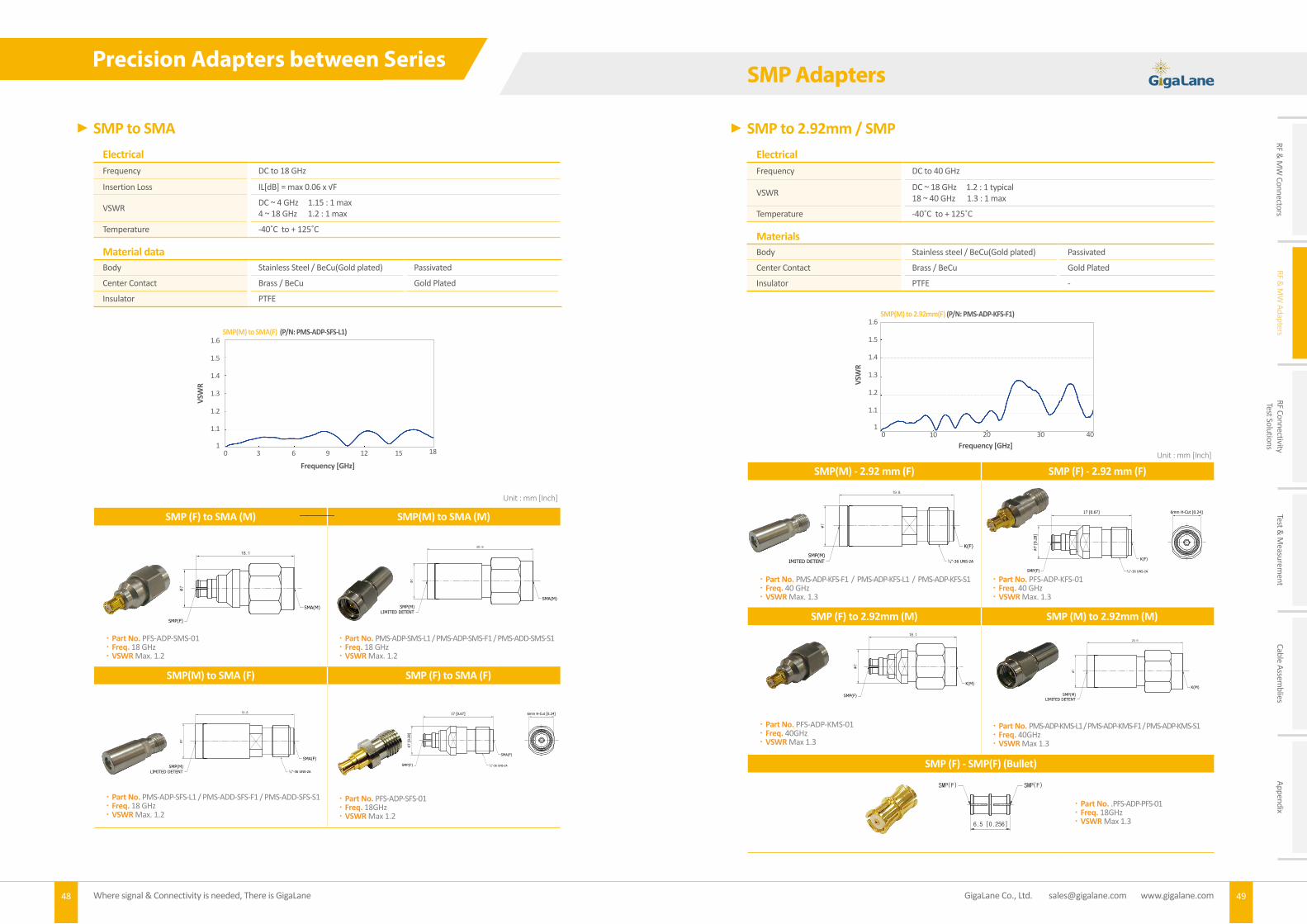
SMP(M) - 2.92 mm (F) SMP (F) - 2.92 mm (F)
Part No. PMS-ADP-KFS-F1 / PMS-ADP-KFS-L1 / PMS-ADP-KFS-S1 Freq. 40 GHz VSWR Max. 1.3
Part No. PFS-ADP-KFS-01 Freq. 40 GHz VSWR Max. 1.3
SMP (F) to 2.92mm (M) SMP (M) to 2.92mm (M)
Part No. PFS-ADP-KMS-01 Freq. 40GHz VSWR Max 1.3
Part No. PMS-ADP-KMS-L1 / PMS-ADP-KMS-F1 / PMS-ADP-KMS-S1 Freq. 40GHz VSWR Max 1.3
48 Where signal & Connectivity is needed, There is GigaLane
2.92mm Connectors
GigaLane Co., Ltd. [email protected] www.gigalane.com 49
SMP Adapters
SMP to SMAElectricalFrequency DC to 18 GHz
Insertion Loss IL[dB] = max 0.06 x √F
VSWR DC ~ 4 GHz 1.15 : 1 max4 ~ 18 GHz 1.2 : 1 max
Temperature -40˚C to + 125˚C
Material dataBody Stainless Steel / BeCu(Gold plated) Passivated
Center Contact Brass / BeCu Gold Plated
Insulator PTFE
SMP (F) to SMA (M) SMP(M) to SMA (M)
Part No. PFS-ADP-SMS-01 Freq. 18 GHz VSWR Max. 1.2
Part No. PMS-ADP-SMS-L1 / PMS-ADP-SMS-F1 / PMS-ADD-SMS-S1 Freq. 18 GHz VSWR Max. 1.2
SMP(M) to SMA (F) SMP (F) to SMA (F)
Part No. PMS-ADP-SFS-L1 / PMS-ADD-SFS-F1 / PMS-ADD-SFS-S1 Freq. 18 GHz VSWR Max. 1.2
Part No. PFS-ADP-SFS-01 Freq. 18GHz VSWR Max 1.2
Unit : mm [Inch]
Unit : mm [Inch]
SMP(M) to SMA(F) (P/N: PMS-ADP-SFS-L1)
Frequency [GHz]
VSW
R
1.6
1.5
1.4
1.3
1.2
1.1
10 63 9 12 15 18
-E.J KIM
PFS-ADP-SMS-01
2016. 01. 18
H.W SONG
K.H JUNG
SMP Female to
SMA Male
Adapter
NOTES
1. MATERIAL
1-1. BOBY : STS (PASSIVATED), BeCu (GOLD PLATED) 1-2. CENTER CONDUCTOR : BeCu (GOLD PLATED) 1-3. INSULATOR : PTFE
2. ELECTRICAL
2-1. IMPEDANCE : 50Ω 2-2. FREQUENCY RANGE : DC to 18GHz 2-3. VSWR(dB) : 1.25 : 1(-19dB)
NS 1 OF 1
mm
REVISIONDESCRIOTION DATE APP.NO DRAWN
www.gigalane.com
Excellence & Innovationin
RF and Microwave GENERAL ANGLES
0 ±0.2 ±2.0°
0.X ±0.1 ±1.0° REV.
This drawing and any data contained herein is the property of Gigalane Co., Ltd. Data is intended for informational propose only.
DATE: TITLE:
UNITS:
TOLERANCE:
ANGLE:
3rd
ANGLE
APPROVED
CHECKED
DRAWN
PRODUCT NO:
SCALE: SHEET :
18.1
∅7
SMP(F)
SMA(M)
-E.J KIM
PMS-ADP-KFS-L1
2016. 01. 18
H.W SONG
K.H JUNG
SMP Male(LIMITED)
to K FemaleAdapter
NOTES
1. MATERIAL
1-1. BOBY : STS (PASSIVATED) 1-2. CENTER CONDUCTOR : BeCu (GOLD PLATED) 1-3. INSULATOR : PTFE
2. ELECTRICAL
2-1. IMPEDANCE : 50Ω 2-2. FREQUENCY RANGE : DC to 40GHz 2-3. VSWR(dB) : DC to 18GHz : 1.25 : 1(-19dB) 18 to 40GHz : 1.35 : 1(-16.5dB)
NS 1 OF 1
mm
REVISIONDESCRIOTION DATE APP.NO DRAWN
www.gigalane.com
Excellence & Innovationin
RF and Microwave GENERAL ANGLES
0 ±0.2 ±2.0°
0.X ±0.1 ±1.0° REV.
This drawing and any data contained herein is the property of Gigalane Co., Ltd. Data is intended for informational propose only.
DATE: TITLE:
UNITS:
TOLERANCE:
ANGLE:
3rd
ANGLE
APPROVED
CHECKED
DRAWN
PRODUCT NO:
SCALE: SHEET :
19.8
∅7
SMP(M)LIMITED DETENT 1
4"-36 UNS-2A
K(F)
-E.J KIM
PMS-ADP-SMS-L1
2016. 01. 18
H.W SONG
K.H JUNG
SMP Male
(LIMITED)
to SMA Male
Adapter
NOTES
1. MATERIAL
1-1. BOBY : STS (PASSIVATED) 1-2. CENTER CONDUCTOR : BRASS (GOLD PLATED) 1-3. INSULATOR : PTFE
2. ELECTRICAL
2-1. IMPEDANCE : 50Ω 2-2. FREQUENCY RANGE : DC to 18GHz 2-3. VSWR(dB) : 1.25 : 1(-19dB)
NS 1 OF 1
mm
REVISIONDESCRIOTION DATE APP.NO DRAWN
www.gigalane.com
Excellence & Innovationin
RF and Microwave GENERAL ANGLES
0 ±0.2 ±2.0°
0.X ±0.1 ±1.0° REV.
This drawing and any data contained herein is the property of Gigalane Co., Ltd. Data is intended for informational propose only.
DATE: TITLE:
UNITS:
TOLERANCE:
ANGLE:
3rd
ANGLE
APPROVED
CHECKED
DRAWN
PRODUCT NO:
SCALE: SHEET :
20.9
∅7
SMP(M)LIMITED DETENT
SMA(M)
-E.J KIM
PFS-ADP-KFS-01
2015. 09. 16
H.W SONG
K.H JUNG
SMP Female to
K Female
Adapter
NOTES
1. MATERIAL
1-1. BOBY : STS (PASSIVATED), BeCu (GOLD PLATED) 1-2. CENTER CONDUCTOR : BeCu (GOLD PLATED) 1-3. INSULATOR : PTFE
2. ELECTRICAL
2-1. IMPEDANCE : 50Ω 2-2. FREQUENCY RANGE : DC to 40GHz 2-3. VSWR(dB) : DC to 18GHz : 1.25 : 1(-19dB) 18 to 40GHz : 1.35 : 1(-16.5dB)
NS 1 OF 1
mm
REVISIONDESCRIOTION DATE APP.NO DRAWN
www.gigalane.com
Excellence & Innovationin
RF and Microwave GENERAL ANGLES
0 ±0.2 ±2.0°
0.X ±0.1 ±1.0° REV.
This drawing and any data contained herein is the property of Gigalane Co., Ltd. Data is intended for informational propose only.
DATE: TITLE:
UNITS:
TOLERANCE:
ANGLE:
3rd
ANGLE
APPROVED
CHECKED
DRAWN
PRODUCT NO:
SCALE: SHEET :
17 [0.67]
∅7 [
0.2
8]
14"-36 UNS-2A
K(F)
SMP(F)
6mm H-Cut [0.24]
-E.J KIM
PMS-ADP-SFS-L1
2016. 01. 18
H.W SONG
K.H JUNG
SMP Male(LIMITED)
to SMA FemaleAdapter
NOTES
1. MATERIAL
1-1. BOBY : STS (PASSIVATED) 1-2. CENTER CONDUCTOR : BeCu (GOLD PLATED) 1-3. INSULATOR : PTFE
2. ELECTRICAL
2-1. IMPEDANCE : 50Ω 2-2. FREQUENCY RANGE : DC to 18GHz 2-3. VSWR(dB) : 1.25 : 1(-19dB)
NS 1 OF 1
mm
REVISIONDESCRIOTION DATE APP.NO DRAWN
www.gigalane.com
Excellence & Innovationin
RF and Microwave GENERAL ANGLES
0 ±0.2 ±2.0°
0.X ±0.1 ±1.0° REV.
This drawing and any data contained herein is the property of Gigalane Co., Ltd. Data is intended for informational propose only.
DATE: TITLE:
UNITS:
TOLERANCE:
ANGLE:
3rd
ANGLE
APPROVED
CHECKED
DRAWN
PRODUCT NO:
SCALE: SHEET :
19.8
∅7
SMP(M)LIMITED DETENT 1
4"-36 UNS-2A
SMA(F)
-E.J KIM
PFS-ADP-SFS-01
2015. 09. 16
H.W SONG
K.H JUNG
SMP Female to
SMA Female
Adapter
NOTES
1. MATERIAL
1-1. BOBY : STS (PASSIVATED), BeCu (GOLD PLATED) 1-2. CENTER CONDUCTOR : BeCu (GOLD PLATED) 1-3. INSULATOR : PTFE
2. ELECTRICAL
2-1. IMPEDANCE : 50Ω 2-2. FREQUENCY RANGE : DC to 18GHz 2-3. VSWR(dB) : 1.25 : 1(-19dB)
NS 1 OF 1
mm
REVISIONDESCRIOTION DATE APP.NO DRAWN
www.gigalane.com
Excellence & Innovationin
RF and Microwave GENERAL ANGLES
0 ±0.2 ±2.0°
0.X ±0.1 ±1.0° REV.
This drawing and any data contained herein is the property of Gigalane Co., Ltd. Data is intended for informational propose only.
DATE: TITLE:
UNITS:
TOLERANCE:
ANGLE:
3rd
ANGLE
APPROVED
CHECKED
DRAWN
PRODUCT NO:
SCALE: SHEET :
17 [0.67]
∅7 [
0.2
8]
14"-36 UNS-2A
SMA(F)
SMP(F)
6mm H-Cut [0.24]
-E.J KIM
PFS-ADP-KMS-01
2016. 01. 18
H.W SONG
K.H JUNG
SMP Female toK MaleAdapter
NOTES
1. MATERIAL
1-1. BOBY : STS (PASSIVATED), BeCu (GOLD PLATED) 1-2. CENTER CONDUCTOR : BeCu (GOLD PLATED) 1-3. INSULATOR : PTFE
2. ELECTRICAL
2-1. IMPEDANCE : 50Ω 2-2. FREQUENCY RANGE : DC to 40GHz 2-3. VSWR(dB) : DC to 18GHz : 1.25 : 1(-19dB) 18 to 40GHz : 1.35 : 1(-16.5dB)
NS 1 OF 1
mm
REVISIONDESCRIOTION DATE APP.NO DRAWN
www.gigalane.com
Excellence & Innovationin
RF and Microwave GENERAL ANGLES
0 ±0.2 ±2.0°
0.X ±0.1 ±1.0° REV.
This drawing and any data contained herein is the property of Gigalane Co., Ltd. Data is intended for informational propose only.
DATE: TITLE:
UNITS:
TOLERANCE:
ANGLE:
3rd
ANGLE
APPROVED
CHECKED
DRAWN
PRODUCT NO:
SCALE: SHEET :
18.1
∅7
SMP(F)
K(M)
-E.J KIM
PMS-ADP-KMS-L1
2016. 01. 18
H.W SONG
K.H JUNG
SMP Male(LIMITED) to K MaleAdapter
NOTES
1. MATERIAL
1-1. BOBY : STS (PASSIVATED) 1-2. CENTER CONDUCTOR : BRASS (GOLD PLATED) 1-3. INSULATOR : PTFE
2. ELECTRICAL
2-1. IMPEDANCE : 50Ω 2-2. FREQUENCY RANGE : DC to 40GHz 2-3. VSWR(dB) : DC to 18GHz : 1.25 : 1(-19dB) 18 to 40GHz : 1.35 : 1(-16.5dB)
NS 1 OF 1
mm
REVISIONDESCRIOTION DATE APP.NO DRAWN
www.gigalane.com
Excellence & Innovationin
RF and Microwave GENERAL ANGLES
0 ±0.2 ±2.0°
0.X ±0.1 ±1.0° REV.
This drawing and any data contained herein is the property of Gigalane Co., Ltd. Data is intended for informational propose only.
DATE: TITLE:
UNITS:
TOLERANCE:
ANGLE:
3rd
ANGLE
APPROVED
CHECKED
DRAWN
PRODUCT NO:
SCALE: SHEET :
20.9
∅7
SMP(M)LIMITED DETENT
K(M)
SMP to 2.92mm / SMPElectricalFrequency DC to 40 GHz
VSWR DC ~ 18 GHz 1.2 : 1 typical18 ~ 40 GHz 1.3 : 1 max
Temperature -40˚C to + 125˚C
MaterialsBody Stainless steel / BeCu(Gold plated) Passivated
Center Contact Brass / BeCu Gold Plated
Insulator PTFE -
SMP(M) to 2.92mm(F) (P/N: PMS-ADP-KFS-F1)
Frequency [GHz]
VSW
R
1.6
1.5
1.4
1.3
1.2
1.1
10 10 20 30 40
Precision Adapters between Series
SMP (F) - SMP(F) (Bullet)
Part No. .PFS-ADP-PFS-01 Freq. 18GHz VSWR Max 1.36.5 [0.256]
PFS-ADP-PFS-01
SMP(F) SMP(F)

RF & M
W Connectors
RF & M
W Adapters
RF ConnectivityTest Solutions
Test & M
easurement
Cable Assemblies
Appendix
50 Where signal & Connectivity is needed, There is GigaLane
2.92mm Connectors
GigaLane Co., Ltd. [email protected] www.gigalane.com 51
BMA (M) - Bulkhead SMA (F) BMA (F) - Bulkhead SMA (F)
Part No. MMS-ADP-SFS-01-BH Freq. 18 GHz VSWR Max. 1.2
Part No. MFS-ADP-SFS-01-BH Freq. 18 GHz VSWR Max. 1.2
BMA (M) - SMA (M) BMA (F) - SMA (F)
Part No. MMS-ADP-SMS-01 Freq. 18 GHz VSWR Max. 1.2
Part No. MFS-ADP-SFS-02 Freq. 18 GHz VSWR Max. 1.2
BMA to SMAElectricalFrequency DC to 18 GHz
Insertion Loss IL[dB] = max 0.06 x √F
VSWR DC ~ 4 GHz 1.1 : 1 max4 ~ 18 GHz 1.3 : 1 max
Temperature -40˚C to + 125˚C
MaterialsBody Stainless steel / BeCu(Gold plated) Passivated
Center Contact Brass / BeCu Gold Plated
Insulator PTFE -
BMA (F) - SMA (M)
Part No. MFS-ADP-SMS-01 Freq. 18 GHz VSWR Max. 1.2
Unit : mm [Inch]
BMA(M) to SMA(M) (P/N: MMS-ADP-SFS-01-BH)
Frequency [GHz]
VSW
R
1.6
1.5
1.4
1.3
1.2
1.1
10 63 9 12 1815
MMS-ADP-SFS-01-BH
Hex 11 [0.433]
Nut(Hex)
8 [0.315]
Washer 1/4"-36 UNS-2A
1/4"-36 UNS-2A
3.2 [0.126] Max Panel
13.1 [0.516]
20.24 [0.797]
1.7 [0.067]
BMA(M) SMA(F)
MFS-ADP-SFS-01-BH
Nut(H-Cut)
8.9 [0.350]
Washer
11 [0.433] 8/25"-72 UNS-2A
1/4"-36 UNS-2A
2.9 [0.114] Max Panel
8.52 [0.335]
15.75 [0.620]
22.75 [0.896]
∅9.45 [0.372]
∅9.5 [0.374] BMA(F) SMA(F)
MMS-ADP-SMS-01
17.45 [0.687]
Hex-Nut 8 [0.315]
BMA(M) SMA(M)
∅6.35 [0.250]
MFS-ADP-SFS-02
16.25 [0.640]
BMA(F) SMA(F)
1/4"-36 UNS-2A
∅6.9 [0.272]
MFS-ADP-SMS-01
17.3 [0.681]
Hex-Nut 8 [0.315]
BMA(F) SMA(M)
∅6.9 [0.272]
BMA Adapters
SMA to SMA / MCXSMA (M) – SMA (M) SMA (M) – SMA (F)
SMA (F) – SMA (F) SMA (M) R/A – SMA (F)
SMA (F) – SMA (F) (4 HOLE, 12.7mm SQUARE) SMA (F) – SMA (F) Bulkhead
SMA Push Type (M) – SMA (F) SMA (F) – MCX (M)
Part No. AMS-ADP-AMS-01 (Ni Plated) AMS-ADP-AMS-02 (Alloy Plated) AMS-ADP-AMS-03 (Gold Plated) Freq. 18 GHz VSWR Max. 1.2
Part No. G06F06FSD018 Freq. 18 GHz VSWR Max. 1.2
Part No. PUS-ADP-AFS-01 (Ni Plated) PUS-ADP-AFS-02 (Gold Plated) Freq. 12 GHz VSWR Max. 1.2
Part No. AMS-ADP-AFS-03 Freq. 18 GHz VSWR Max. 1.2
Part No. AMR-ADP-AFS-02 Freq. 6 GHz VSWR Max. 1.2
Part No. AFS-ADP-AFS-01-4H Freq. 18 GHz VSWR Max. 1.45
Part No. AFS-ADP-AFS-03-BH Freq. 18 GHz VSWR Max. 1.2
Part No. AFS-ADP-DMS-01 Freq. 6 GHz VSWR Max. 1.2
12.6 [0.496]
5.6 [0.220]
21 [0.827]
SMA(F)
1/4"-36 UNS-2A Hex-Nut 8 [0.315]
SMA(M)
H Cut 5.4 [0.213]
AMS-ADP-AFS-03
21 [0.827]
Hex-Nut 8 [0.315] Hex-Nut 8 [0.315]
SMA(M)SMA(M)
AMS-ADP-AMS-01
SCALE:
NS
APPROVED
CHECK
DRAWNSHEET/OF
1/1
Product NO:
3rdANGLE
mm
ANGLE:
TOLEARANCE:
UNIT:
DATE:
REVISIONDESCRIOTION DATE APPROVEDNO DRAWN
www.gigalane.com
Excellence & Innovationin
RF and Microwave
TITLE:
GENERAL ANGLES
0 ±0.2 ±2.0°
0.X ±0.1 ±1.0° Rev.
This drawing and any data contained herein is the property of Gigalane Co., Ltd. Data is intended for informational propose only.
NOTE
1. Material
1-1. Body : Brass (Nickel Plated) 1-2. Center Conductor : BeCu (Gold Plated) 1-3. Insulator : PTFE
2. Elerctrical
2-1. Impeadance : 50Ω 2-2. Frequency range : DC to 12GHz 2-3. VSWR(dB) : 1.2 : 1(-21dB)
-Y.J KIM
G06F06FSD018
2015. 11. 05
H.Y SONG
K.H JUNG
SMA(F) to SMA(F)ADAPTER
A1
20.2 [0.795]
11.1 [0.437]
2 [0.079]
Hex 7.9 [0.311]
SMA(F) SMA(F)
1/4"-36 UNS-2A 1/4"-36 UNS-2A
17.5 [0.689]
11.2
5 [0
.443
]
6.5 [0.256]
14.5
[0.
571]
Hex-Nut 8 [0.315]
1/4"-36 UNS-2A
AMR-ADP-AFS-02
1.7 [0.067]
9.5 [0.374]
22.3 [0.878]
SMA(F)
1/4"-36 UNS-2A
SMA(F)
1/4"-36 UNS-2A
8.6 [0.339]
12.7 [0.500]
4-2.6 [0.102]
AFS-ADP-AFS-01-4H
Nut(Hex)
8 [0.315]
Washer
1/4"-36 UNS-2A
1/4"-36 UNS-2A
SMA(F)SMA(F)
6.2 [0.244] Max Panel
1.7 [0.067]
22.2 [0.874]
5.8 [0.228]
Hex 8 [0.315]
AFS-ADP-AFS-03-BH
1/4"-36 UNS-2A
SMA(F)
12.25 [0.482]
18.75 [0.738]
SMA(M)
Cross Knurl
∅8.9 [0.350]
PUS-ADP-AFS-01
AFS-ADP-DMS-01
1/4"-36 UNS-2A
SMA(F)MCX(M)
6.5 [0.256]
9 [0.354]
4.2 [0.165]
6.7 [0.262]
23.1 [0.907]
Cross Knual
∅9.0 [0.354]
Unit : mm [Inch]
Standard Adapters

GigaLane Co., Ltd. [email protected] www.gigalane.com 53
RF & M
W Connectors
RF & M
W Adapters
RF ConnectivityTest Solutions
Test & M
easurement
Cable Assemblies
Appendix
GigaLane Co., Ltd. [email protected] www.gigalane.com 53
Standard Adapters
52 Where signal & Connectivity is needed, There is GigaLane
- Board to Board connectors- Quick Lock connector- GigaLane Mobile Coaxial Micro- FRC
RF Connectivity Test Solutions
N to SMA
N to N
N (M) – SMA (M) N (M) – SMA (F)
N (F) – SMA (M) N (F) – SMA (F)
N (M) – N (M) N (M) – N (F) Push Type
N (F) – N (F)
Part No. NMS-ADP-AMS-01 (Ni Plated) NMS-ADP-AMS-02 (Alloy Plated) Freq. 12 GHz VSWR Max. 1.2
Part No. NMS-ADP-NMS-01 (Ni Plated) Freq. 8 GHz VSWR Max. 1.2
Part No. NFS-ADP-AMS-01 (Ni Plated) NFS-ADP-AMS-02 (Alloy Plated) Freq. 12 GHz VSWR Max. 1.2
Part No. NFS-ADP-NFS-01 (Ni Plated) NFS-ADP-NFS-02 (Alloy Plated) Freq. 8 GHz VSWR Max. 1.2
Part No. NMS-ADP-AFS-01 (Ni Plated) NMS-ADP-AFS-02 (Alloy Plated) Freq. 12 GHz VSWR Max. 1.2
Part No. PUS-ADP-NFS-01 Freq. 8 GHz VSWR Max. 1.2
Part No. NFS-ADP-AFS-01 (Ni Plated) NFS-ADP-AFS-02 (Alloy Plated) Freq. 12 GHz VSWR Max. 1.2
Unit : mm [Inch]
Unit : mm [Inch]
NMS-ADP-AMS-01
32 [1.260]
17.1 [0.673]
Nut(Hex)
8 [0.315]
N(M)
SMA(M)
Cross Knurl
∅20.5 [0.807]
NMS-ADP-AFS-01
17.1 [0.673]
30.9 [1.217]
1/4"-36 UNS-2A
N(M)
SMA(F)
Cross Knurl
∅20.5 [0.807]
NFS-ADP-AMS-02
8.2 [0.323]
19.2 [0.756]
32.1 [1.264]
Nut(Hex)
8 [0.315]
5/8"-24 UNEF-2A
N(F)
SMA(M)
Cross Knurl
∅17.5 [0.689]
NFS-ADP-AFS-01
8.2 [0.323]
19.2 [0.756]
31.5 [1.240]
5/8"-24 UNEF-2A
1/4"-36 UNS-2AN(F)
SMA(F)
Cross Knurl
∅17.5 [0.689]
NMS-ADP-NMS-01
17.1 [0.673]
25 [0.984]
42.1 [1.657]
N(M) N(M)
Cross Knurl
∅20.5 [0.807]Cross Knurl
∅20.5 [0.807]
PUS-ADP-NFS-01
15.5 [0.610]
27 [1.063]
5/8"-24 UNEF-2A
35 [1.378]
N(F)P-SMA(M)
Cross Knurl
∅18.05 [0.711]
NFS-ADP-NFS-01
5/8"-24 UNEF-2A5/8"-24 UNEF-2A
14.38 [0.566]
24 [0.945]
38 [1.496]
N(F)N(F)

GigaLane Co., Ltd. [email protected] www.gigalane.com54 55Where signal & Connectivity is needed, There is GigaLane
RF & M
W Connectors
RF & M
W Adapters
RF ConnectivityTest Solutions
Test & M
easurement
Cable Assemblies
Appendix
Board to Board connector for 085 Cable (F) Board to Board connector for 085 Cable(M)
Board to board connector(F) Board to board connector(M)
Board to board connector(F)
Board to Board Connector
GigaLane Board to Board connectors are especially developed for board-to-board and board-to-module RF interconnections. It is the perfect solution for multiple connections from board-to-board and complex stack-ups in radio module applications.
SpecificationElectrical
Connector for 085 cable(12mm) Board to board connector(15/18mm)
Frequency DC ~ 6 GHz DC ~ 6 GHz
Impedance 50 Ω 50 Ω
VSWR 1.3 : 1 (@6GHz) 1.25:1(@6GHz)
Insulation Resistance 5000 MΩ 5000 MΩ
Dielectric Withstand Voltage 1250 Vrms max 1250 Vrms max
Contact Resistance- Outer Conductor- Inner Conductor
10 mΩ max8 mΩ max
6 mΩ max4 mΩ max
Insertion Loss 0.18 dB max (@6GHz) 0.15 dB max (@6GHz)
RF Leakage Min. 70 dB Min. 75 dB
Power Handling 280 W @ 3.1GHz 280 W @ 3.1GHz
Mechanical Mating Cycle (Durability) 200
Recommended Mating TorqueProof Torque
Engagement : Max. 1.4 kgfDisengagement : Max. 0.9 kgf
Center Contact Retention Force Min. 1.5 kgf
Distance between PCBs 12mm/15mm/18mm Type
EnvironmentalTemperature -40°C ~ +125°C
Thermal Shock MIL-STD-202, Method 107, Condition B
Corrosion (salt Spray) MIL-STD-202 Method 101, Condition B
Shock MIL-STD-202, Method 213, Condition A
Vibration MIL-STD-202, Method 204, Condition B
Moisture Resistance MIL-STD-202, Method 106
MaterialsBody Brass BeCu SUCO Plated
Center Contact Brass BeCu Ag Plated
Insulator PTFE -
Misalignment Tolerance
PCB to PCB Axial working range Radial working Range
12mm 13~14mm ±0.8mm
15mm 14~16mm ±0.8mm
18mm 17~19mm ±1.0mm
Board to Board Connector
Female
Available Connections
male
Part No. G18RFC001-C12mm Distance between PCBs. 12mm
Part No. G18SFB001-P15mm-2.2 Distance between PCBs. 15mm
Part No. G18RMC001-C12mm
Part No. G18SMB005-P-1.6
Part No. G18SFB001-P18mm-2.2 Distance between PCBs. 18mm
Unit : mm [Inch]
Board to Board connector can be connected with various type and suitable for multiple connections.
① G18SMB005-P-1.6 : G18SFB001-P15mm-2.2② G18SMB005-P-1.6 : G18SFB001-P18mm-2.2③ G18RFC001-C12mm : G18SFB001-P18mm-2.2
④ G18SFB001-P15mm-2.2 : G18RMC001-12mm⑤ G18RMC001-12mm : G18RFC001-C12mm⑥ G18RFC001-C12mm : G18SMB005-P-1.6
① ②
③
④
⑤ ⑥

GigaLane Co., Ltd. [email protected] www.gigalane.com56 57Where signal & Connectivity is needed, There is GigaLane
RF & M
W Connectors
RF & M
W Adapters
RF ConnectivityTest Solutions
Test & M
easurement
Cable Assemblies
Appendix
SMA Quick Lock Cable Assembly
GigaLane Quick Lock connectors are especially suitable where connector should be connected fast and quick with low loss. Self-Locking feature allows the connector to be engaged with SMA connector easily and stably. It is also easy to separate with Quick Lock Connector and SMA connector. SMA Connector is well-matched with SMA Quick Lock Connector.
G132
SF085(Gray Jacket)
RG316 MF141
SpecificationElectricalFrequency DC ~ 6 GHz
Impedance 50 Ω
VSWR 1.3 : 1 (-18dB, Typical)
Insulation Loss 1.70dB @ 3GHz2.50dB @ 6GHz
Insulation Resistance 1000 MΩ Min.
Center Contact Resistance < 3 mΩ
Outer Contact Resistance < 2 mΩ
Working Voltage 500 Vrms
Mechanical Mating Cycle 100 Min.
Mating Force Mating Force : ~3.0 kgf Max.De-mating Force : ~4.0 kgf Max.
Mating Height 30mm
EnvironmentalTemperature range -40°C~+100°
Thermal Shock MIL-STD-202, Method 107, Condition B
Corrosion (salt Spray) MIL-STD-202, Method 101, Condition B
Shock MIL-STD-202, Method 213, Condition A
Vibration MIL-STD-202, Method 204, Condition B
Moisture Resistance MIL-STD-202, Method 106
Materials
Connector
Body Brass (SUCO plated),Brass (Ni plated)
Center Conductor BeCu (Ag plated)
Insulator PTFE
Quick Lock Cable Assembly
Quick Lock Male connector (M) for cable assembly
Quick Lock Female connector (F) for cable assembly
Quick Lock Female connector (M)
Male
Female
Part No. G06RMC035 Available cable. SF085. MF141. RG316, G132 Matching connector. SMA Female connector, G06SFB103
Part No. G06RFC016 Available cable. SF085. MF141. RG316, G132 Matching connector. SMA Male Connector, G06RMC035
Part No. G06SFB103 Available cable. SF085. MF141. RG316, G132 Matching connector. SMA Male Connector, G06RMC035
Unit : mm [Inch]
Test Result (G06RMC035-G132-450mm)
Test Result (G06RFC016-SF085GJ-70mm)
PCB Pattern
* Including Test PCB Loss
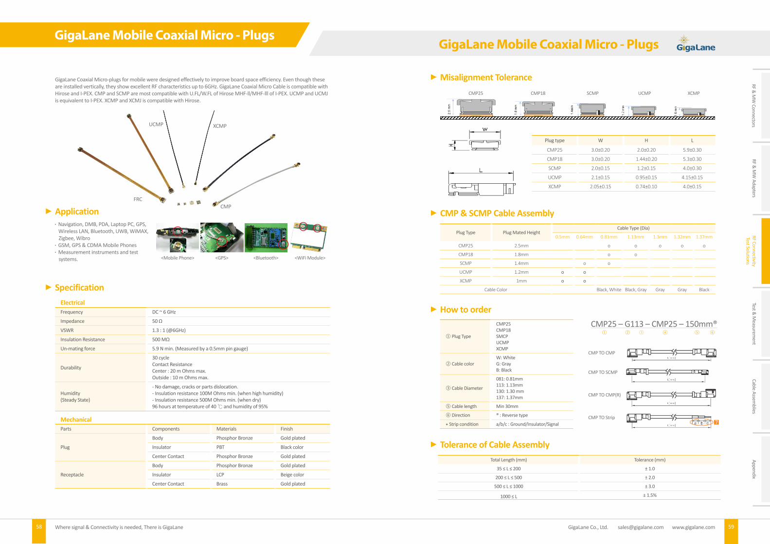
GigaLane Co., Ltd. [email protected] www.gigalane.com58 59Where signal & Connectivity is needed, There is GigaLane
RF & M
W Connectors
RF & M
W Adapters
RF ConnectivityTest Solutions
Test & M
easurement
Cable Assemblies
Appendix
GigaLane Mobile Coaxial Micro - Plugs
GigaLane Coaxial Micro-plugs for mobile were designed effectively to improve board space efficiency. Even though these are installed vertically, they show excellent RF characteristics up to 6GHz. GigaLane Coaxial Micro Cable is compatible with Hirose and I-PEX. CMP and SCMP are most compatible with U.FL/W.FL of Hirose MHF-ll/MHF-lll of I-PEX. UCMP and UCMJ is equivalent to I-PEX. XCMP and XCMJ is compatible with Hirose.
<Mobile Phone> <GPS> <Bluetooth> <WiFi Module>
Specification
Application
ElectricalFrequency DC ~ 6 GHz
Impedance 50 Ω
VSWR 1.3 : 1 (@6GHz)
Insulation Resistance 500 MΩ
Un-mating force 5.9 N min. (Measured by a 0.5mm pin gauge)
Durability
30 cycleContact ResistanceCenter : 20 m Ohms max.Outside : 10 m Ohms max.
Humidity(Steady State)
- No damage, cracks or parts dislocation.- Insulation resistance 100M Ohms min. (when high humidity)- Insulation resistance 500M Ohms min. (when dry)96 hours at temperature of 40 and humidity of 95%
Mechanical Parts Components Materials Finish
Plug
Body Phosphor Bronze Gold plated
Insulator PBT Black color
Center Contact Phosphor Bronze Gold plated
Receptacle
Body Phosphor Bronze Gold plated
Insulator LCP Beige color
Center Contact Brass Gold plated
① Plug Type
CMP25CMP18SMCP UCMP XCMP
② Cable color W: White G: Gray B: Black
③ Cable Diameter
081: 0.81mm 113: 1.13mm 130: 1.30 mm 137: 1.37mm
⑤ Cable length Min 30mm
⑥ Direction ® : Reverse type
* Strip condition a/b/c : Ground/Insulator/Signal
Total Length (mm) Tolerance (mm)
35 ≤ L ≤ 200 ± 1.0
200 ≤ L ≤ 500 ± 2.0
500 ≤ L ≤ 1000 ± 3.0
1000 ≤ L ± 1.5%
Navigation, DMB, PDA, Laptop PC, GPS, Wireless LAN, Bluetooth, UWB, WiMAX, Zigbee, Wibro GSM, GPS & CDMA Mobile Phones Measurement instruments and test systems.
GigaLane Mobile Coaxial Micro - Plugs
Misalignment Tolerance
CMP & SCMP Cable Assembly
How to order
Tolerance of Cable Assembly
Plug type W H L
CMP25 3.0±0.20 2.0±0.20 5.9±0.30
CMP18 3.0±0.20 1.44±0.20 5.3±0.30
SCMP 2.0±0.15 1.2±0.15 4.0±0.30
UCMP 2.1±0.15 0.95±0.15 4.15±0.15
XCMP 2.05±0.15 0.74±0.10 4.0±0.15
Plug Type Plug Mated Height Cable Type (Dia)
0.5mm 0.64mm 0.81mm 1.13mm 1.3mm 1.32mm 1.37mm
CMP25 2.5mm o o o o o
CMP18 1.8mm o o
SCMP 1.4mm o o
UCMP 1.2mm o o
XCMP 1mm o o
Cable Color Black, White Black, Gray Gray Gray Black
CMP25 CMP18 SCMP UCMP XCMP
CMP25 – G113 – CMP25 – 150mm®① ② ③ ④ ⑤ ⑥
CMP TO CMP
CMP TO SCMP
CMP TO CMP(R)
CMP TO Strip
FRC
UCMP XCMP
CMP

GigaLane Co., Ltd. [email protected] www.gigalane.com60 61Where signal & Connectivity is needed, There is GigaLane
RF & M
W Connectors
RF & M
W Adapters
RF ConnectivityTest Solutions
Test & M
easurement
Cable Assemblies
Appendix
Connectors for CMP cable
GigaLane CMP Application Cable Assemblies
CMP25 – G113 – XXXXX – 120mm①
① Cable type: G113/G130② Connector: See Connectors for CMP cable②
Type. SMA Plug(M) Part No. CAMS2
Type. SMA Jack(F) Part No. CAFS1
Type. SMA Bulkhead Jack(F) Part No. CAFS3
Type. Right Angle SMA Jack(F) Part No. CAFR1
Type. Right Angle MCX Jack(F) Part No. CDFR2
Type. MCX Plug(M) Part No. CEMS1
Type. Right Angle SMA Plug(M) Part No. CAMR2
GigaLane Mobile Coaxial Micro - Test Solution
GigaLane is providing a test solution which allow customer can save their test cost and time. This Mobile cable assembly has designed for mobile test solution and operates up to 3GHz.
Configuration
NO. Part Name DESCRIPTION Part NO. QTY NOTES
①
②
③
SCALE:
NS
APPROVED
CHECK
DRAWNSHEET/OF
1/1
Product NO:
3rdANGLE
mm
ANGLE:
TOLEARANCE:
UNIT:
DATE:
REVISIONDESCRIOTION DATE APPROVEDNO DRAWN
www.gigalane.com
Excellence & Innovationin
RF and Microwave
TITLE:
GENERAL ANGLES
0 ±0.2 ±2.0°
0.X ±0.1 ±1.0° Rev.
This drawing and any data contained herein is the property of Gigalane Co., Ltd. Data is intended for informational propose only.-Y.J KIM
G56F04FSD001 /G04RMC001-B137G1-G06SFC096-102mm
2016. 02. 23
H.Y SONG
K.H JUNG
SMP(M) R/A BeCu G04RMC001 1
UCMP to SMP(F) Adapter
/ SMP(M) to SMA(F)B137G1
Cable Assembly
A1
SMA(F) ST Brass G06SFC096 1
UCMP to SMP(F) Adapter Brass G56F04FSD001 1
NOTE
1. Elerctrical
1-1. Impeadance : 50Ω 1-2. Frequency range : DC to 3GHz 1-3. VSWR(dB) : 1.35 : 1(-16.5dB) 1-4. Temperature : -40 to +90
2. UCMP to SMP Adapter의 X, Y축 최대 유동 거리
2-1. X 축 : -0.5mm ~ +0.5mm
2-2. Y 축 : -0.5mm ~ +0.5mm
④ Cable - B137G1 1
⑤ Shrink Tube - SCL-1/8-0 2
L[mm]
②④ 14"-36 UNS-2A
HEX 7.9mm⑤(2
3.9)
∅3
∅7.4
③
①
Ref.
Min 0.5mm
Max 1.5mm
X
Y
Z
0
<Note 2 - 참조>
Part No.
Description UCMP to SMP(F)/SMP(M) to SMA(F)B137G1 Cable assembly
① SMP(M) R/A G04SMC001
② SMA(F) Straight G06SFC096
③ UCMP to SMP(F) G56F04FSD001
④ Cable Black 137 Cable
How to orderG56F04FSD001/G04RMC001-B137G1-G06SFC096-102mm
②③+① ④
③+① UCMP to SMP(F) + SMP(M) R/A④ Cable② SMA(F) Straight
SpecificationElectricalFrequency DC ~ 3 GHz
Impedance 50 Ω DC ~ 3 GHz
VSWR 1.35 : 1 (@3GHz)
Temperature -40°C ~ +90°C
Maximum Misalignment of UCMPto SMP Adapter
X : -0.5mm ~ +0.5mmY : -0.5mm ~ +0.5mm

GigaLane Co., Ltd. [email protected] www.gigalane.com 63
RF & M
W Connectors
RF & M
W Adapters
RF ConnectivityTest Solutions
Test & M
easurement
Cable Assemblies
Appendix
62 Where signal & Connectivity is needed, There is GigaLane
- 3.5mm & N-Type & Din Type Calibration Kits - TDR Probe - Attenuators - Termination
Test & Measurement
FRC (FPCB RF Cable)
GigaLane FRC(FPCB RF Cable) is designed for optimum RF transmission using flat flexible transmission line up to 6GHz. This is ideal for mobile phone and antenna application. GigaLane FRC provides a solution of flexible design options for various interconnection applications.
Specification
Cable Assembly Drawing Connector Drawing
ElectricalFrequency DC ~ 6GHz
Impedance 50Ω
Insertion Loss 0.93dB @3GHz_50mm
VSWR 1.4 : 1 (@3GHz)
EnvironmentalTemperature -40°C ~ +90°C
Thermal Shock MIL-STD-202, Method 107, Test Condition B
Corrosion (salt Spray) MIL-STD-202, Method 101, Condition B, 5% salt
Vibration MIL-STD-202, Method 204, Condition D
Moisture Resistance MIL-STD-202, Method 106
MaterialsConnector Body Phosphor Bronze(Au Plated)
Connector Pin Phosphor Bronze(Au Plated)
Connector Insulator LCP
FPCB Polyimide Film, Adhesive, Copper(Au Plated), Epoxy
Connector Dimension
SVMP
UVMP
XVMP

RF & M
W Connectors
RF & M
W Adapters
RF ConnectivityTest Solutions
Test & M
easurement
Cable Assemblies
Appendix
2.92mm Connectors
64 Where signal & Connectivity is needed, There is GigaLane
3.5mm & N-Type & DIN Type Calibration Kits
GigaLane Calibration kits are designed for correcting inappropriate measurements of devices under test using a VNA up to 9 GHz. Calibration kit enables precise and repeatable measurement based on high-quality matching technology and precise processing technology. This components can be applied to all common VNAs. GigaLane has developed of 3.5mm Male & Female set (9 GHz), N-type Male & Female set (4 GHz), DIN type male (4 GHz) products.
3.5mm Male & Female set (9 GHz): 3.5mm vector network analyzer calibration kits contain both male/plug and female/jack connector interfaces to perform a full two port error corrections. VNA calibration kits are designed for equipment that utilizes the open-short-load calibration method. N-type Male & Female set (4 GHz): N-type Calibration kit is designed to calibrate a wide range of VNA models. VNA calibrations kit are designed for equipment utilizes a short, open, load calibration technique. DIN type male (4 GHz) products: DIN type calibration kits are designed for test measurement.
*Each Calibration kit is housed in a durable, protective wood box and includes a present torque wrench.
General Information Applied to all common VNAs Development of 3.5mm Male & Female Set (9 GHz) N type Male & Female Set (6 GHz, 4 GHz) DIN Type Male (4 GHz)
Part No. GCS35M-9G-MS
Part No. GPA35M-MM Freq. DC to 26.5 GHz VSWR Max 1.2
Part No. GPA35M-MF Freq. DC to 26.5 GHz VSWR Max 1.2
Part No. GPA35M-FF Freq. DC to 26.5 GHz VSWR Max 1.2
Part No. GCS35M-9G-FS
Part No. GTW8M (0.9N.m) Torque 0.9 N.m ± 3% (8lbs. Inch) Head Opening 8.1 mm (0.319 inch) for 8mm (0.315 inch) nut Length 163mm (6.42 inch) Weight 140 g (4.94 oz)
3.5mm Full Set 3.5mm Economy Set
Part No. GCS35M-9G
- Male Set, Female Set- 3 Phase Matched Adapter- Torque wrench- Wood Case
Part No. GCS35M-9G-ES
- Male Set, Female Set- Wood Case
GigaLane Co., Ltd. [email protected] www.gigalane.com 65
Specification
GCS35M-9G GCSN-6G-MSGCSN-4G-MS
GCSD-4G-MSGCSN-4G-FS
Connector 3.5mm N N DIN
Max Frequency 9 GHz 6 GHz 4 GHz 4 GHz
S11 < -38 dB < -40 dB < -40 dB < -40 dB
Phase Deviation of Open, Shot < ±1.5° < ±1.5° < ±1.5° < ±1.5°
Material Stainless Steel with Gold Plating Stainless Steel Stainless Steel Stainless Steel
N-Type Male Set (6 GHz) N-Type Male Set (4 GHz)
Part No. GCSN-6G-MS Part No. GCSN-4G-MS
N-Type Female Set (4 GHz) DIN-Type Male Set (4 GHz)
Part No. GCSN-4G-FS Part No. GCSD-4G-MS
3.5mm & N-Type & DIN Type Calibration Kits

RF & M
W Connectors
RF & M
W Adapters
RF ConnectivityTest Solutions
Test & M
easurement
Cable Assemblies
Appendix
2.92mm Connectors
Where signal & Connectivity is needed, There is GigaLane66
TDR Probe
GigaLane TDR Probe is most useful when performing the Time Domain Reflectometry (TDR) measurement on the board. It is designed to provide optimized solution for difficult installation and measurement of connectors. The embedded spring structure enables a stable contact between ground and signal. The pitches between signal and ground pins can be designed and adjustable to 5 different specifications; 1.0 1.27 1.65 2.0 2.5mm
Part No. GLT-TDRP-K-01 Frequency range DC to 10 GHz Insertion Loss < 1.2 dB Return Loss > 10 dB Connector 2.92mm K-type Probe Pitch 1.0 ~ 2.5mm
NOTE
1. Material
1-1. Body : Brass (Gold Plated) 1-2. Conductor : Brass(C3604)(Gold Plated) 1-3. Insulator : PTFE
2. Elerctrical
2-1. Impeadance : 50Ω 2-2. Frequency range : DC to 10GHz 2-3. VSWR(dB) : 1.92 : 1(-10dB)
3. Probe pitch : 1.0 ~ 2.5mm
AE.J KIM
GLT-TDRP-K-01
2013. 09. 30
D.D KANG
J.I JEON
TDR Probe - GLT-TDRP-K-01 1
TDR Probe
NO. Part Name DESCRIPTION Part NO. QTY NOTES
①
②
③
④
SCALE:
NS
APPROVED
CHECK
DRAWNSHEET/OF
1/1
Product NO:
3rd
ANGLE
mm
ANGLE:
TOLEARANCE:
UNIT:
DATE:
REVISIONDESCRIOTION DATE APPROVEDNO DRAWN
www.gigalane.com
Excellence & Innovationin
RF and Microwave
TITLE:
GENERAL ANGLES
0 ±0.2 ±2.0°
0.X ±0.1 ±1.0° Rev.
This drawing and any data contained herein is the property of Gigalane Co., Ltd. Data is intended for informational propose only.
A1
HEX 8mm
GigaLane
29.3
8.4
∅8
3 6.75
2.92mm(K) Female7mm H-Cut
A1
Outline change from Hexagon to Circle 2013.10.02 E.J KIM J.I JEON
Frequency [GHz]
S21(
dB)
0
-5
-10
-15
-20
-25
-30
-35
-400 2 4 6 8 10
S-parameter S11[dB] S21[dB]
GigaLane Co., Ltd. [email protected] www.gigalane.com 67
Termination
GigaLane SMA type Fixed Attenuators show excellent electrical performance from DC to 3GHz. Users can choose the value that they want among various attenuation values.
Attenuators
SMA (M) Type
N (M) Type GLTT-001
13.3 [0.524]
4.9 [0.193]
Hex-Nut 8 [0.315]
∅6.4
[0.
250]
GLTT-005
33.1 [1.301]
∅19 [0.748]
∅20.5 [0.807]
Part No. GLAT-C Series Frequency range DC to 3 GHz VSWR 1.2 RF Power 2 W average Impedance 50 Ω Body Material Brass with Gold Plated Pin Material BeCu with Gold Plated Weight 7g Temp. range -55 to + 125
Attenuation Value 1 ~ 10, 15, 20, 30 dB Attenuation accuracy +/- 0.5 dB Part No. GLAT-C-XX dB (XX : Attenuation Value
Ex) 3 dB Hexa Attenuator : GLAT-C-3dB
Part No. GLTT-001 Frequency range Max 3 GHz VSWR < 1.2 Power 1W avg @ 25
Impedance 50 Ω Temp. range -55 to + 125
Body Material Brass with Gold Plated
Part No. GLTT-005 Frequency range Max 3 GHz VSWR < 1.2 Power 1W avg @ 25
Impedance 50 Ω Temp. range -55 to + 125
Body Material Brass with Alloy Plated

RF & M
W Connectors
RF & M
W Adapters
RF ConnectivityTest Solutions
Test & M
easurement
Cable Assemblies
Appendix
68 Where signal & Connectivity is needed, There is GigaLane
Cable Assemblies- GL Series- GUL Series- Airborne Series- MF Series- SR Series- SF Series- Suitable Connectors for Cable- Specifying Assembly Length
GigaLane Co., Ltd. [email protected] www.gigalane.com 69
GL Series Flexible Low Loss Microwave cable assembly - GL140s - GL200 - GL200s - GL200sC01
GUL Series Flexible Ultra Low Loss Microwave cable assembly - GUL180 - GUL310
Airborne Series Airborne Microwave cable assembly - GLA210 - GULA320
MF Series Multiflex Microwave Cable Assembly - MF085 - MF141
SR Series Semi-Rigid Microwave Cable Assembly - SR085 - SR141
SF Series Semi-Flexible(handformable) Microwave Cable Assembly - SF085 - SF141

RF & M
W Connectors
RF & M
W Adapters
RF ConnectivityTest Solutions
Test & M
easurement
Cable Assemblies
Appendix
GUL Series
GL SeriesFlexible Low Loss Microwave Cable Assembly
Flexible Ultra Low Loss Microwave Cable Assembly
Airborne Series Airborne Microwave Cable Assembly
70 Where signal & Connectivity is needed, There is GigaLane
Product Groups
SR Series
MF SeriesMultiflex Microwave Cable Assembly
Semi-Rigid Microwave Cable Assembly
SF Series Semi-Flexible(Handformable) Microwave Cable Assembly
GigaLane Co., Ltd. [email protected] www.gigalane.com 71

RF & M
W Connectors
RF & M
W Adapters
RF ConnectivityTest Solutions
Test & M
easurement
Cable Assemblies
Appendix
72 Where signal & Connectivity is needed, There is GigaLane
GL Series Flexible Low Loss Microwave Cable Assembly
GigaLane GL Series cable assemblies perform in the range of frequency usage that is applicable up to 40 GHz . Center conductor consists of Stranded and Solid center conductor. By using Low density PTFE(extruded) dielectric, a value of the lowest insertion loss is extracted. These are specialized in providing excellent shielding effectiveness, flexibility and durability and supplied in fields of Commercial, Military RF & microwave airborne systems, Test & Measurement applications (Lab & Production line, Anechoic Chamber).GigaLane provides two types of Neck type for GL cable assembly. One is sleeve type to strengthen the neck area of connector and gives a comfort grip which provides easiness in assembling connectors. Another is shrink tube type which is suitable for applying to small space.
GigaLane Co., Ltd. [email protected] www.gigalane.com 73
Features and benefits
Cable Design
Description Diameter (mm)
① Center conductor Silver-plated copper wire, stranded 19/0.2
② Dielectric Low density PTFE (extruded) -
③ Inner shield Silver-plated copper tape -
④ Outer shield Silver-plated copper braid -
⑤ Jacket Extruded FEP 4.20
Electrical Impedance 50 Ω
Operating frequency 40 GHz
Capacitance 86 pF/m
Velocity of propagation 77 % nom.
Time delay 4.35 ns/m
RF leakage (dB) <-100
Dielectric constant 1.7
Phase stability vs. flexure (@18 GHz max.) 4°
IL stability vs. flexure (dB @minimum BR) ± 0.3
Phase stability vs. temp. (deg/GHz/m) (-40 ~ 80°) < 2°
Mechanical & EnvironmentalMinimum bend radius (mm) 19.05
Weight (g/m) 42
Temperature -55 to + 135
Suitable Connectors
Cable selection Standard Connector selection max. VSWR
SMA type N type 2.9mm type Connector
P/N Frequency Attenuation (dB/m) Straight R/A Straight R/A Straight ST to ST ST to R/A R/A to R/A
GL140sB02 6 GHz 0.88 SMS114SMS114B* SMR114 NMS114 NMR114B - 1.15 1.2 1.25
GL140sC 18 GHz 1.62 SMS122 SMS122B* - - - 1.25 - -
GL140sD 26.5 GHz 1.98 SMS115 SMS115B* - - - 1.25 - -
GL140sE 40 GHz 2.52 - - - KMS116 1.35 - -
* Please refer to connector drawing on p. 82 * xxx xxxB : Shrink Tube Type ex) SMS114B
Frequency ranges from DC to 40 GHz Low density PTFE(extruded) dielectric Low Loss and Flexibility Excellent shielding effectiveness and return loss Durability Cost-efficient
① ② ③ ④ ⑤
GL140s Cable

GigaLane Co., Ltd. [email protected] www.gigalane.com 75
RF & M
W Connectors
RF & M
W Adapters
RF ConnectivityTest Solutions
Test & M
easurement
Cable Assemblies
Appendix
GL140s Cable
74 Where signal & Connectivity is needed, There is GigaLane
Cable Insertion & Stability with Flexure
Cable Phase Stability with Temperature
Cable Attenuation & Power
Test Result
GL140s
GL140s
GL140s
Inse
rtio
n Lo
ss C
hang
e [d
B]Ph
ase
Chan
ge [D
eg]
Aver
age
Pow
er R
atin
g [W
]
Frequency [GHz]
Temperature [°C]
Frequency [GHz]
-0.4
-0.5
0
-0.3
0
200
-0.2
0.5
400
-0.1
1
600
0
1.5
800
0.1
2
1000
0.2
2.5
1200
0.3
1400
0.4
160018002000
0
-60 -40 -20 0 20 40 60 80 100
3
5
6
10 15
9
20
12
25
15
30 35
18
40
GL140s
GL140s
GL140s
KMS116-GL140sE-KMS116-1M
Pha
se C
hang
e [d
eg]
Phas
e Ch
ange
[PPM
]At
tenu
atio
n [d
B/m
] R
etur
n Lo
ss [d
B]
Inse
rtio
n Lo
ss [d
B]
Frequency [GHz]
Temperature [°C]
Frequency [GHz]
Frequency [GHz]
-4
-200
0.0
-3
0
0.5
-2
200
1.0
-1
400
1.5
0
600
2.0
1
800
2.5
2
1000
3.0
3
1200
3.5
4
1400
1600
4.04.5
0
0
0
2
5
5
4
10
6
15
8 10
20
10 15
12
25
20 25 30 35 40
14
30
16
35 40
18
S21()
S21()
Spec(Uper&Lower)
Spec(Uper&Lower)
-50 -50
-40 -40
-30 -30
-20 -20
-10 -10
0 0
-60 -40 -20 0 20 40 60 80 100
Features and benefits
Cable Design
DescriptionDiameter (mm)
GL200 GL200s
① Center conductor GL200: Silver-plated copper wire, solid GL200s: Silver-plated copper wire, stranded 1.39 19/0.3
② Dielectric Low density PTFE (extruded) - -
③ Inner shield Silver-plated copper tape - -
④ Outer shield Silver-plated copper braid - -
⑤ Jacket Extruded FEP 5.70 5.70
Electrical Impedance 50 Ω
Operating frequency 18 GHz
Capacitance 85 pF/m
Velocity of propagation 77 % nom.
Time delay 4.35 ns/m
RF leakage (dB) -100
Dielectric constant 1.7
Phase stability vs. flexure (@18 GHz max.) 5°
IL stability vs. flexure (dB @minimum BR) ± 0.3
Phase stability vs. temp. (deg/GHz/m) (-40 ~ 80°) < 2 °
Mechanical & EnvironmentalMinimum bend radius (mm) 29.2
Weight (g/m) 70
Temperature -55 to + 135
Suitable Connectors
Cable selection Standard Connector selection max. VSWR
SMA type N type TNCA type Connector
P/N Frequency Attenuation (dB/m) Straight R/A Straight R/A Straight ST to ST ST to R/A R/A to R/A
GL200C 18 GHz 1.15 SMS111SMS111B* SMR111
NMS111NFS111(Jack)
NMR111 G24SMC001 1.25 1.35 1.45
GL200D 26.5 GHz 1.43 SMS112 SMS112B* - - - - 1.25 - -
GL200sC 18 GHz 1.19 SMS111SMS111B* SMR111
NMS111NFS111(Jack)
NMR111 G24SMC001 1.25 1.35 1.45
GL200sD 26.5 GHz 1.45 SMS112 SMS112B* - - - - 1.25 - -
* Please refer to connector drawing on p. 83 * XXX XXXB: Shrink Tube ex)SMS111B
Frequency ranges from DC to 26.5 GHz Low density PTFE(extruded) dielectric Low Loss and Flexibility Excellent shielding effectiveness and return loss Durability Cost-efficient
GL200 & GL200s Cable
① ② ③ ④ ⑤
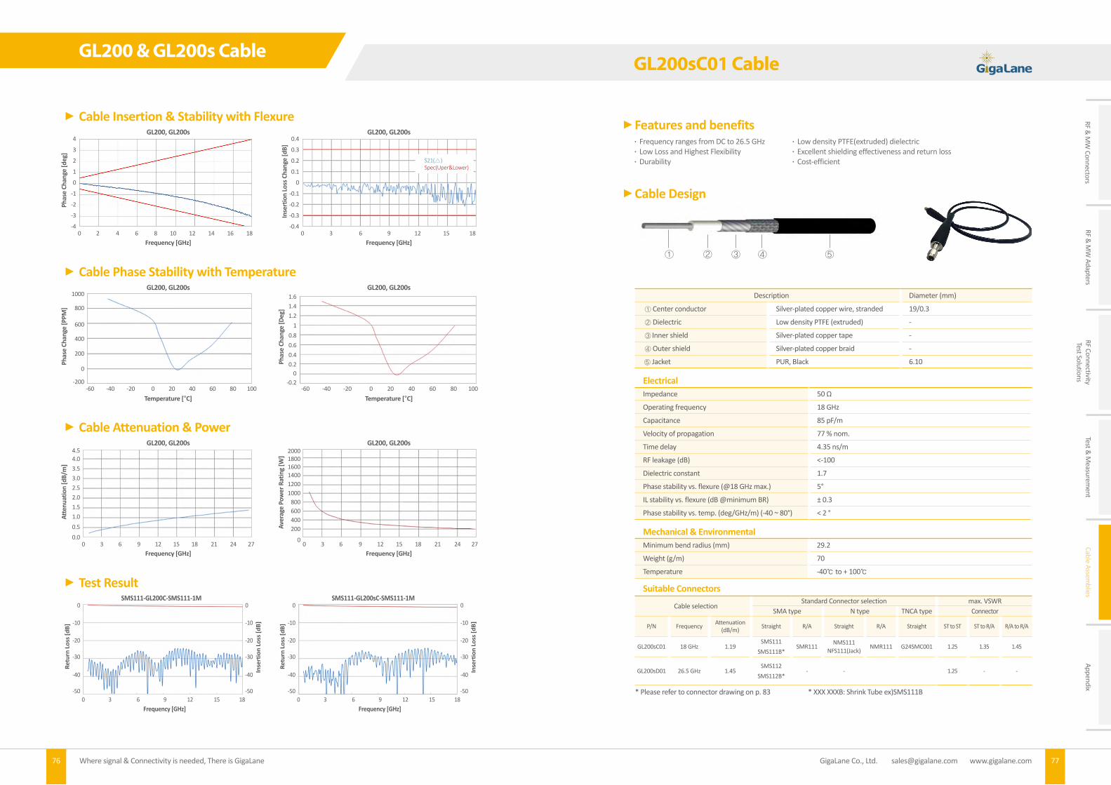
RF & M
W Connectors
RF & M
W Adapters
RF ConnectivityTest Solutions
Test & M
easurement
Cable Assemblies
Appendix
GL200 & GL200s Cable
76 Where signal & Connectivity is needed, There is GigaLane
Cable Insertion & Stability with Flexure
Cable Phase Stability with Temperature
Cable Attenuation & Power
Test Result
GL200, GL200s
GL200, GL200s
GL200, GL200s
Inse
rtio
n Lo
ss C
hang
e [d
B]Ph
ase
Chan
ge [D
eg]
Frequency [GHz]
Temperature [°C]
Frequency [GHz]
-0.4
-0.2
0
-0.3
0
200
-0.2
0.2
400
-0.1
0.4
600
0
0.60.8
800
0.1
1.21.41.6
1000
0.2
1
1200
0.3
1400
0.4
160018002000
0
-60-60 -40-40 -20-20 00 2020 4040 6060 8080 100100
3 6 9 12 15 18
GL200, GL200s
GL200, GL200s
GL200, GL200s
SMS111-GL200C-SMS111-1M SMS111-GL200sC-SMS111-1M
Pha
se C
hang
e [d
eg]
Phas
e Ch
ange
[PPM
] R
etur
n Lo
ss [d
B]
Ret
urn
Loss
[dB]
Inse
rtio
n Lo
ss [d
B]
Inse
rtio
n Lo
ss [d
B]
Frequency [GHz]
Temperature [°C]
Frequency [GHz]
Frequency [GHz] Frequency [GHz]
-4
-200
0.0
-3
0
0.5
-2
200
1.0
-1
400
1.5
0
600
2.0
1
800
2.5
2
1000
3.0
3
3.5
4
4.04.5
0
0 0
0 0
2
3 3
3 3
4
6 6
6
9 9
8 10
12 12
6 69 9
12
15 15
12 1215 1518 18
14
18 18
16
21 2124 2427 27
18
S21()Spec(Uper&Lower)
-50 -50-50 -50
-40 -40-40 -40
-30 -30-30 -30
-20 -20-20 -20
-10 -10-10 -10
0 00 0
S21()Spec(Uper&Lower)
Aver
age
Pow
er R
atin
g [W
]
Atte
nuat
ion
[dB/
m]
GigaLane Co., Ltd. [email protected] www.gigalane.com 77
Features and benefits
Cable Design
Description Diameter (mm)
① Center conductor Silver-plated copper wire, stranded 19/0.3
② Dielectric Low density PTFE (extruded) -
③ Inner shield Silver-plated copper tape -
④ Outer shield Silver-plated copper braid -
⑤ Jacket PUR, Black 6.10
ElectricalImpedance 50 Ω
Operating frequency 18 GHz
Capacitance 85 pF/m
Velocity of propagation 77 % nom.
Time delay 4.35 ns/m
RF leakage (dB) <-100
Dielectric constant 1.7
Phase stability vs. flexure (@18 GHz max.) 5°
IL stability vs. flexure (dB @minimum BR) ± 0.3
Phase stability vs. temp. (deg/GHz/m) (-40 ~ 80°) < 2 °
Mechanical & EnvironmentalMinimum bend radius (mm) 29.2
Weight (g/m) 70
Temperature -40 to + 100
Suitable Connectors
Cable selection Standard Connector selection max. VSWR
SMA type N type TNCA type Connector
P/N Frequency Attenuation (dB/m) Straight R/A Straight R/A Straight ST to ST ST to R/A R/A to R/A
GL200sC01 18 GHz 1.19SMS111
SMS111B*SMR111
NMS111 NFS111(Jack)
NMR111 G24SMC001 1.25 1.35 1.45
GL200sD01 26.5 GHz 1.45SMS112
SMS112B*- - 1.25 - -
* Please refer to connector drawing on p. 83 * XXX XXXB: Shrink Tube ex)SMS111B
Frequency ranges from DC to 26.5 GHz Low density PTFE(extruded) dielectric Low Loss and Highest Flexibility Excellent shielding effectiveness and return loss Durability Cost-efficient
GL200sC01 Cable
① ② ③ ④ ⑤

Cable Insertion & Stability with Flexure
Cable Phase Stability with Temperature
Cable Attenuation & Power
Test Result
GL200sC01
GL200sC01
GL200sC01
Inse
rtio
n Lo
ss C
hang
e [d
B]Ph
ase
Chan
ge [D
eg]
Frequency [GHz]
Temperature [°C]
Frequency [GHz]
-0.4
-0.2
0
-0.3
0
200
-0.2
0.2
400
-0.1
0.4
600
0
0.60.8
800
0.1
1.21.41.6
1000
0.2
1
1200
0.3
1400
0.4
160018002000
0
-60-60 -40-40 -20-20 00 2020 4040 6060 8080 100100
3 6 9 12 15 18
GL200sC01
GL200sC01
GL200sC01
SMS111-GL200sC01-SMS111-1M
Pha
se C
hang
e [d
eg]
Phas
e Ch
ange
[PPM
] R
etur
n Lo
ss [d
B]
Inse
rtio
n Lo
ss [d
B]
Frequency [GHz]
Temperature [°C]
Frequency [GHz]
Frequency [GHz]
-4
-200
0.0
-3
0
0.5
-2
200
1.0
-1
400
1.5
0
600
2.0
1
800
2.5
2
1000
3.0
3
3.5
4
4.04.5
0
0 0
0
2
3 3
3
4
6 6
6
9 9
8 10
12 12
6 9
12
15 15
12 15 18
14
18 18
16
21 2124 2427 27
18
-50 -50
-40 -40
-30 -30
-20 -20
-10 -10
0 0
GL200sC01 Cable
78 Where signal & Connectivity is needed, There is GigaLane
S21()Spec(Uper&Lower)
Aver
age
Pow
er R
atin
g [W
]
Atte
nuat
ion
[dB/
m]
GigaLane Co., Ltd. [email protected] www.gigalane.com 79
GUL Series Flexible Ultra Low LossMicrowave Cable Assembly
GigaLane GUL Series cable assemblies perform range of frequency usage is applicable up to 18 GHz. Center conductor consists of Solid center conductor, By using Ultra low density PTFE(taped) dielectric, it maintains its excellent phase stability and a value of the lowest insertion loss is extracted. These are specialized in providing excellent shielding effectiveness, flexibility and durability and supplied in fields of Commercial, Military RF & microwave airborne systems, Test & Measurement applications (Lab & Production line, Anechoic Chamber).GigaLane provides two types of Neck type for GL cable assembly. One is sleeve type to strengthen the neck area of connector and gives a comfort which provides easiness in assembling connectors. Another is shrink tube type which is suitable for applying to small space.

RF & M
W Connectors
RF & M
W Adapters
RF ConnectivityTest Solutions
Test & M
easurement
Cable Assemblies
Appendix
GUL180 & GUL310 Cable
80 Where signal & Connectivity is needed, There is GigaLane80
Features and benefits
Cable Design
DescriptionDiameter (mm)
GUL180C GUL310C
① Center conductor Silver-plated copper wire, solid 1.29 2.35
② Dielectric Ultra low density PTFE(taped) - -
③ Inner shield Silver-plated copper tape - -
④ Outer shield Silver-plated copper braid - -
⑤ Jacket Extruded FEP 5.00 7.90
ElectricalImpedance 50 Ω
Operating frequency 18 GHz
Capacitance 78 pF/m
Velocity of propagation 84 % nom.
Time delay 3.95 ns/m
RF leakage (dB) -100
Dielectric constant 1.4
Phase stability vs. flexure (@18 GHz max.) 3°
IL stability vs. flexure (dB @minimum BR) ± 0.1
Phase stability vs. temp. (deg/GHz/m) (-40 ~ 80°) < 2 °
Mechanical & Environmental GUL180C
Minimum bend radius (mm) 25.4 48.5
Weight (g/m) 51 115
Temperature -55 to + 165 -55 to + 165
Suitable Connectors
Cable selection Standard Connector selection max. VSWR
SMA type N type Connector
P/N Frequency Attenuation (dB/m) Straight R/A Straight R/A ST to ST ST to R/A R/A to R/A
GUL180C 18 GHz 1.22 SMS119 SMR119 NMS119 NMR119 1.25 1.35 1.45
GUL310C 18 GHz 0.78 SMS120 SMR120B* NMS120 NMR120B* 1.25 1.35 1.45
* Please refer to connector drawing on p. 83 * XXX XXXB: Shrink Tube ex)SMS120B
Frequency ranges from DC to 18 GHz Ultra low density PTFE(taped) dielectric Low Loss and Flexibility Excellent phase stability and lowest insertion loss Excellent shielding effectiveness Durability Cost-efficient
① ② ③ ④ ⑤
GigaLane Co., Ltd. [email protected] www.gigalane.com 81
Cable Insertion & Stability with Flexure
Cable Phase Stability with Temperature
Cable Attenuation & Power
GUL180
GUL180
GUL180
Inse
rtio
n Lo
ss C
hang
e [d
B]Ph
ase
Chan
ge [D
eg]
Frequency [GHz]
Temperature [°C]
Frequency [GHz]
-0.4
-1
0
-0.3
0
200
-0.2
1
400
-0.1
2
600
0
3
800
0.1
1000
0.2
1200
0.3
1400
0.4
160018002000
0
-60-60 -40-40 -20-20 00 2020 4040 6060 8080 100 120100 120
3 6 9 12 15 18
GUL180
GUL180
GUL180
Pha
se C
hang
e [d
eg]
Phas
e Ch
ange
[PPM
]
Frequency [GHz]
Temperature [°C]
Frequency [GHz]
-4
-200
0.0
-3
0
0.5
-2
200
1.0
-1
400
1.5
0
600
2.0
1
800
2.5
2
10001200
1400
1600
3.0
3
3.5
4
4.04.5
0
0 0
2
3 3
4
6 6
6
9 9
8 10
12 12
12
15 15
14
18 18
16 18
GUL180 Cable
S21()Spec(Uper&Lower)
Aver
age
Pow
er R
atin
g [W
]
Atte
nuat
ion
[dB/
m]
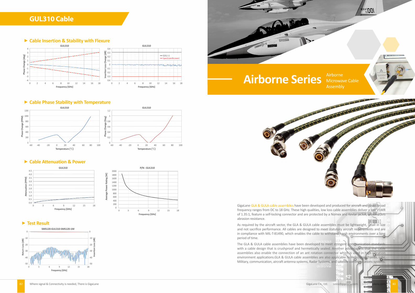
GigaLane Co., Ltd. [email protected] www.gigalane.comWhere signal & Connectivity is needed, There is GigaLane82
Cable Insertion & Stability with Flexure
Frequency [GHz]
Phas
e Ch
ange
[deg
]
4
3
2
1
0
-1
-2
-3
-40 2 4 6 8 10 12 14 16 18
GUL310
Frequency [GHz]
Inse
rtio
n Lo
ss C
hang
e [d
B]
0.4
0.3
0.2
0.1
0
0.1
0.2
0.3
0.40 2 4 6 8 10 12 14 16 18
GUL310
S21()Spec(Uper&Lower)
Cable Phase Stability with Temperature1200
1000
800
600
400
200
0
Temperature [°C] Temperature [°C]
Phas
e Ch
ange
[PPM
]
-60 -40 -20 0 20 40 60 80 100
GUL310Ph
ase
Chan
ge [D
eg]
1.2
1
0.8
0.6
0.4
0.2
0-60 -40 -20 0 20 40 60 80 100
GUL310
Airborne Series AirborneMicrowave CableAssembly
GigaLane GLA & GULA cable assemblies have been developed and produced for aircraft and cover broad frequency ranges from DC to 18 GHz. These high qualities, low loss cable assemblies deliver a low VSWR of 1.35:1, feature a self-locking connector and are protected by a Nomex and Kevlar jacket, which offers abrasion resistance.
As required by the aircraft sector, the GLA & GULA cable assemblies must be lightweight, small in size and not sacrifice performance. All cables are designed to meet statutory aircraft requirements and are in compliance with MIL-T-81490, which enables the cable to withstand harsh environments over a long period of time.
The GLA & GULA cable assemblies have been developed to meet stringent communication standards with a cable design that is crushproof and hermetically sealed. Another advantage is that the cable assemblies also enable the connection of an ant rotation connector which is used in high vibration environment applications.GLA & GULA cable assemblies are also applicable to Helicopter, Trainer, UAV, Military, communication, aircraft antenna systems, Radar Systems, and satellite communications systems.
83
GUL310 Cable
Cable Attenuation & Power
Frequency [GHz]
4.54.03.53.02.52.01.51.00.50.0
0 3 6 9 12 15 18
GUL310
Atte
nuat
ion
[PPM
]
Aver
age
Pow
er R
atin
g [W
]
200018001600140012001000
800600400200
0
Frequency [GHz]0 3 6 9 12 15 18
P/N : GUL310
Test ResultSMS120-GUL310-SMS120-1M
Ret
urn
Loss
[dB]
Inse
rtio
n Lo
ss [d
B]
Frequency [GHz]0 3 6 9 12 15 18
-50 -50
-40 -40
-30 -30
-20 -20
-10 -10
0 0

Where signal & Connectivity is needed, There is GigaLane84 GigaLane Co., Ltd. [email protected] www.gigalane.com
Features and benefits
Cable Design
DescriptionDiameter (mm)
GLA210 GULA320
① Center conductor GLA210 : Silver-plated copper wire, SoldGULA320 : Silver-plated copper clad Aluminum - -
② Dielectric GLA210 : Low density PTFEGULA320 : Ultra low density PTFE - -
③ Inner shield Silver-plated copper tape - -④ Outer shield Silver-plated copper braid - -⑤ Vapor layer High temperature tape - -⑤ Jacket Nomex & Kevlar 5.90 8.00
ElectricalGLA210 GULA320
Impedance 50 Ω 50 ΩOperating frequency 18 GHz 18 GHzCapacitance 86 pF/m 78 pF/mVelocity of propagation 77% nom. 84% nom.Time delay 4.35 ns/m 3.95 ns/mRF leakage (dB) -100 -100Dielectric constant 1.7 1.4
Mechanical & EnvironmentalGUL180C
Minimum bend radius (mm) 29.2 44 Weight (g/m) 60 95 Temperature -55°C to + 200 °C -55°C to + 200°C
Suitable Connectors
Cable selection Standard Connector selection
SMA type TNCA type N type TNC type DrawingPageP/N Frequency Straight R/A Straight R/A Straight R/A Straight R/A
GLA2103 GHz - - - - - - TMS401M TMR401M 84p
18 GHz - - TAMS420M - - - - - 84p
GULA3203 GHz - -
TAMS403MTAFS401M
(Jack, Bulkead)
TAFRA401M(45°)(Jack, Bulkead)TAFRA402M(90°)(Jack, Bulkead)
TMR402M(45°)TAMRA401M(90°)TAMRA402M(90°)TAMRA403M(45°)
- NAMRA401M - - 84p
18 GHz SMS401M - TAMS401M - - - - - 84p
Frequency ranges from DC to 18 GHz Hermetically sealed (vapor sealed) Compliance with MIL-T-81490 Lightweight Anti rotation connector
GLA210 & GULA320 Cable
① ② ③ ④ ⑤ ⑥MF Series Multiflex
Microwave Cable Assembly
GigaLane MF cable assemblies are complete products of flexible up to 40 GHz. MF cable is more flexible than SF cable and its cost effectiveness provides amicableness to Test Labs as well as test equipments where demand lots of replaceable cables.
85

Where signal & Connectivity is needed, There is GigaLane86 87 GigaLane Co., Ltd. [email protected] www.gigalane.com
RF & M
W Connectors
RF & M
W Adapters
RF ConnectivityTest Solutions
Test & M
easurement
Cable Assemblies
Appendix
Features and benefits
Cable Design
DescriptionDiameter (mm)
MF085 MF141 ① Center conductor Silver-plated copper wire 0.51 0.92
② Dielectric Solid PTFE - -
③ 1st outer conductor Silver-plated copper tape - -
④ 2nd outer conductor Silver-plated copper braid - -
⑤ Jacket Fluorinated Ethylene Propylene, blue 2.68 4.14
ElectricalMF085 MF141
Impedance 50 Ω 50 Ω
Operating frequency 40 GHz 30 GHz
Capacitance 95 pF/m 95 pF/m
Velocity of propagation 70.6% nom. 70.6% nom.
Time delay 4.7 ns/m 4.7 ns/m
RF leakage (dB) <-100 <-100
Mechanical & EnvironmentalMF085 MF141
Minimum bend radius (mm) 6 10
Weight (g/m) 21 45
Temperature -55 C to + 135 C -55 C to + 135 C
Suitable Connectors
Cable selection Standard Connector selection
SMA type N type 29.2mm type DrawingPageP/N Frequency (GHz) Straight R/A Straight R/A Straight R/A
MF085
18 GHz SMS101
SFS101 (Jack)SBS101(Jack, Bulkhead)
- - - - - 85p
40 GHz - - - -KMS101
KFS101(Jack)KBS101(Jack, Bulkhead)
- 85p
MF141
18 GHzSMS102
SFS102 (Jack)SBS102(Jack, Bulkhead)
- NMS101 - - - 85p
30 GHz - - - -KMS103
KFS103 (Jack)KBS103 (Jack, Bulkhead)
- 85p
Frequency ranges from DC to 40 GHz High Flexibility Cost-efficient
MF085 & MF141 Cable
① ② ③ ④ ⑤
Attenuation & Power
6
4.5
3
1.5
0
Frequency [GHz]
Atte
nuat
ion
[dB/
m]
0 5 10 15 20 25 30 35 40
• MF085 Attenuation
0 5 10 15 20 25 30 35 40
• MF085 Power
Frequency [GHz]
Pow
er [W
]
150
100
50
0
Frequency [GHz]
Atte
nuat
ion
[dB/
m]
4
3
2
1
00 5 10 15 20 25 30
• MF141 Attenuation • MF141 Power
Pow
er [W
]
400
300
200
100
00 5 10 15 20 25 30
Frequency [GHz]
Test Result
Frequency [GHz]
Retu
rn Lo
ss [d
B]
0
-10
-20
-30
-40
-50
Inse
rtio
n Lo
ss [d
B]
0
-2
-4
-6
-8
-100 5 10 15 20 25 30 35 40
KBS101-MF085-KBS101-1M
Frequency [GHz]
Retu
rn Lo
ss [d
B]
0
-10
-20
-30
-40
-50
Inse
rtio
n Lo
ss [d
B]
0
-1
-2
-3
-4
-50 3 6 9 12 15 18
SMS102-MF141-SMS102-1M
MF085 & MF141 Cable

89 GigaLane Co., Ltd. [email protected] www.gigalane.com
RF & M
W Connectors
RF & M
W Adapters
RF ConnectivityTest Solutions
Test & M
easurement
Cable Assemblies
Appendix
SR Series Semi-RigidMicrowave Cable Assembly
GigaLane Semi-Rigid cable assemblies lead to an excellent electrical performance up to 40 GHz. SR cable is easily bendable so that can be fitted into requested shapes while maintaining its set after bending. It is ideal for use with automated bending equipment as well as Hands of man power using bending tools.
Where signal & Connectivity is needed, There is GigaLane88
SR085 & SR141 Cable
Features and benefits
Cable Design
Frequency ranges from DC to 40 GHz Fits into the small systems Cost-efficient
① ② ③
DescriptionDiameter (mm)
SR085 SR141 ① Center conductor Silver-plated copper wire 0.51 0.92
② Dielectric Solid PTFE - -
③ 1st outer conductor Seamless copper tubing, tin-plated 2.2 3.58
ElectricalSR085 SR141
Impedance 50 Ω 50 Ω
Operating frequency 40 GHz 30 GHz
Capacitance 95 pF/m 95 pF/m
Velocity of propagation 69% nom. 69.5% nom.
Time delay 4.82 ns/m 4.82 ns/m
RF leakage (dB) -100 -100
Mechanical & EnvironmentalSR085 SR141
Minimum bend radius (mm) 3.18 6.35
Weight (g/m) 21 45
Temperature -40 C to + 125 C -40 C to 125 C
Suitable Connectors
Cable selection Standard Connector selection
SMA type N type 2.92mm type DrawingPageP/N Frequency (GHz) Straight R/A Straight R/A Straight R/A
SR085
18 GHz SMS302
SFS302(Jack)SBS302(Jack, Bulkhead)
- - - - - 86p
40 GHz - - - -KMS301
KFS301(Jack)KBS301(Jack, Bulkhead)
- 86p
SR141
18 GHzSMS303
SFS303(Jack)SBS303(Jack, Bulkhead)
- - - - - 86p
30 GHz - - - -KMS303
KFS303(Jack)KBS303(Jack, Bulkhead)
- 86p

Where signal & Connectivity is needed, There is GigaLane90 GigaLane Co., Ltd. [email protected] www.gigalane.com
Frequency [GHz]
Retu
rn Lo
ss [d
B]
0
-10
-20
-30
-40
-50
Inse
rtio
n Lo
ss [d
B]
0
-2
-4
-6
-8
-100 5 10 15 20 25 30 35 40
KMS301-SR085-KMS301-0.5M KFS303-SR141-KFS303-0.5M
Frequency [GHz]
Retu
rn Lo
ss [d
B]
0
-10
-20
-30
-40
-50
Inse
rtio
n Lo
ss [d
B]
0
-1
-2
-3
-4
-50 3 6 9 12 15 18
SF Series Semi-Flexible(handformable) Microwave Cable Assembly
GigaLane Semi-Flexible cable assemblies provide a complete high performance up to 40 GHz. The cable design is the same with SR Cable but have a tin-soaked copper braid for the outer conductor. it gives hand-formability and suitable where the coaxial cable fit into a tight space without performance loss.
Attenuation & Power
6
4
2
0
Frequency [GHz]
Atte
nuat
ion
[dB/
m]
0 5 10 15 20 25 30 35 40
• SR085 Attenuation
Frequency [GHz]
Atte
nuat
ion
[dB/
m]
3
2
1
00 5 10 15 20 25 30
• SR141 Attenuation • SR141 Power
Pow
er [W
]
500
400
300
200
100
00 5 10 15 20 25 30
Frequency [GHz]
Test Result
91
SR085 & SR141 Cable

Where signal & Connectivity is needed, There is GigaLane92 93 GigaLane Co., Ltd. [email protected] www.gigalane.com
RF & M
W Connectors
RF & M
W Adapters
RF ConnectivityTest Solutions
Test & M
easurement
Cable Assemblies
Appendix
Features and benefits
Cable Design
DescriptionDiameter (mm)
SF085 SF141 ① Center conductor Silver-plated copper wire, Solid 0.52 0.94
② Dielectric Solid PTFE - -
③ Outer Shield Tinned Copper - -
④ Jacket Fluorinated Ethylene Propylene 2.78 4.58
ElectricalSF085 SF141
Impedance 50 Ω 50 Ω
Operating frequency 40 GHz 30 GHz
Capacitance 95 pF/m 95 pF/m
Velocity of propagation 71% nom. 71% nom.
Time delay 4.7 ns/m 4.7 ns/m
RF leakage (dB) -100 -100
Mechanical & EnvironmentalSF085 SF141
Minimum bend radius (mm) 6 10
Weight (g/m) 21 45
Temperature -40 C to + 125 C -40 C to + 125 C
Suitable Connectors
Cable selection Standard Connector selection
SMA type N type 2.92mm type DrawingPageP/N Frequency (GHz) Straight R/A Straight R/A Straight R/A
SF085
18 GHz SMS302
SFS302(Jack)SBS302(Jack, Bulkhead)
- - - - - 87p
40 GHz - - - -KMS301
KFS301(Jack)KBS301(Jack, Bulkhead)
- 87p
SF141
18 GHzSMS303
SFS303(Jack)SBS303(Jack, Bulkhead)
- - - - - 87p
30 GHz - - - -KMS303
KFS303(Jack)KBS303(Jack, Bulkhead)
- 87p
Frequency ranges from DC to 40 GHz Hand-formability Good flexibility Cost-efficient
① ② ④③
SF085 & SF141 Cable
Frequency [GHz]
Retu
rn Lo
ss [d
B]
0
-10
-20
-30
-40
-50
Inse
rtio
n Lo
ss [d
B]
0
-2
-4
-6
-8
-100 5 10 15 20 25 30 35 40
KMS301-SF085-KMS301-0.5M KMS303-SF141-KFS303-0.5M
Frequency [GHz]
Retu
rn Lo
ss [d
B]
0
-10
-20
-30
-40
-50
Inse
rtio
n Lo
ss [d
B]
0
-1
-2
-3
-4
-50 3 6 9 12 15 18
Attenuation & Power
6
4
2
0
Frequency [GHz]
Atte
nuat
ion
[dB/
m]
0 5 10 15 20 25 30 35 40
• SF085 Attenuation
0 5 10 15 20 25 30 35 40
• SF085 Power
Frequency [GHz]
Pow
er [W
]
400
300
200
100
0
Frequency [GHz]
Atte
nuat
ion
[dB/
m]
4
3
2
1
00 5 10 15 20 25 30
• SF141 Attenuation • SF141 Power
Pow
er [W
]
500
400
300
200
100
00 5 10 15 20 25 30
Frequency [GHz]
Test Result
SF085 & SF141 Cable
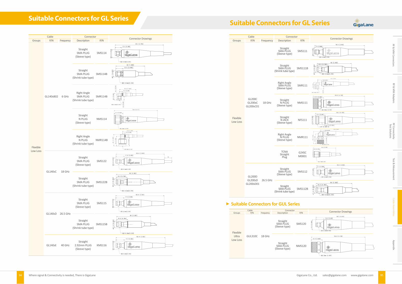
Where signal & Connectivity is needed, There is GigaLane94 95 GigaLane Co., Ltd. [email protected] www.gigalane.com
RF & M
W Connectors
RF & M
W Adapters
RF ConnectivityTest Solutions
Test & M
easurement
Cable Assemblies
Appendix
Cable ConnectorConnector Drawings
Groups P/N Frequency Description P/N
Flexible Low Loss
GL140sB02 6 GHz
StraightSMA PLUG
(Sleeve type)SMS114
StraightSMA PLUG
(Shrink tube type)SMS114B
Right AngleSMA PLUG
(Shrink tube type)SMR114B
StraightN PLUG
(Sleeve type)NMS114
Right AngleN PLUG
(Shrink tube type)NMR114B
GL140sC 18 GHz
StraightSMA PLUG
(Sleeve type)SMS122
StraightSMA PLUG
(Shrink tube type)SMS122B
GL140sD 26.5 GHz
StraightSMA PLUG
(Sleeve type)SMS115
StraightSMA PLUG
(Shrink tube type)SMS115B
GL140sE 40 GHzStraight
2.92mm PLUG(Sleeve type)
KMS116
12.4 [0.488]
95.4 [3.756]
∅15.6 [0.614]
G06SMC065(구-SMS114)
HEX 8.0mm[0.318]
17.41 [0.685]
100.41 [3.953]
15
∅15.6 [0.614]
G06SMC067(구-SMS122)
HEX 8.0mm[0.318]
HEX 8.0mm[0.318]
∅11.5 [0.453]
19.9 [0.784]
60 [2.362]
SMS122B
HEX 8.0mm[0.318]
∅11.5 [0.453]
19.9 [0.784]
60 [2.362]
SMS115B
17.4 [0.685]
100.41 [3.953]
∅15.6 [0.614]
G06SMC056(구-SMS115)
HEX 8.0mm[0.318]
17.4 [0.685]
100.41 [3.953]
∅15.6 [0.614]
G06SMC056(구-SMS115)
HEX 8.0mm[0.318]
21.5 [0.845]
104.4 [4.111]
HEX 20mm [0.787]
NMS114
30.1 [1.185]
25.5 [1.004]
21.3 [0.837]
6.8 [0.268]
37.6 [1.478]
HEX 20mm [0.787]
G07RMC008(구-NMR114)
6.6 [0.260]
37.4 [1.470]
13.1 [0.514]
16.4 [0.644]
8.8 [0.347]
G06RMC028(구-SMR114)
HEX 8.0mm[0.318]
HEX 8.0mm[0.318]
∅11 [0.433]
12.5 [0.492]
50 [1.969]
SMS114B
Suitable Connectors for GL SeriesSuitable Connectors for GL Series
Cable Connector Connector DrawingsGroups P/N Frequency Description P/N
Flexible Ultra
Low LossGUL310C 18 GHz
StraightSMA PLUG
(Sleeve type)SMS120
StraightSMA PLUG
(Sleeve type)NMS120
Cable ConnectorConnector Drawings
Groups P/N Frequency Description P/N
Flexible Low Loss
GL200CGL200sC
GL200sC0118 GHz
StraightSMA PLUG
(Sleeve type)SMS111
StraightSMA PLUG
(Shrink tube type)SMS111B
Right AngleSMA PLUG
(Sleeve type)SMR111
StraightN PLUG
(Sleeve type)NMS111
StraightN JACK
(Sleeve type)NFS111
Right AngleN PLUG
(Sleeve type)NMR111
TCNAStraight
PlugG24SCM0001
GL200DGL200sD
GL200sD0126.5 GHz
StraightSMA PLUG
(Sleeve type)SMS112
StraightSMA PLUG
(Shrink tube type)SMS112B
96.4 [3.793]
16 [
0.63
0]
20 [
0.78
7]
13.4 [0.526]
8 [0
.315
]
G06RMC027(구-SMR111)
HEX 8.0mm[0.318]
Suitable Connectors for GUL Series
G24SMC001
HEX 15mm[0.591]
18.3 [0.720]
58.3 [2.295]
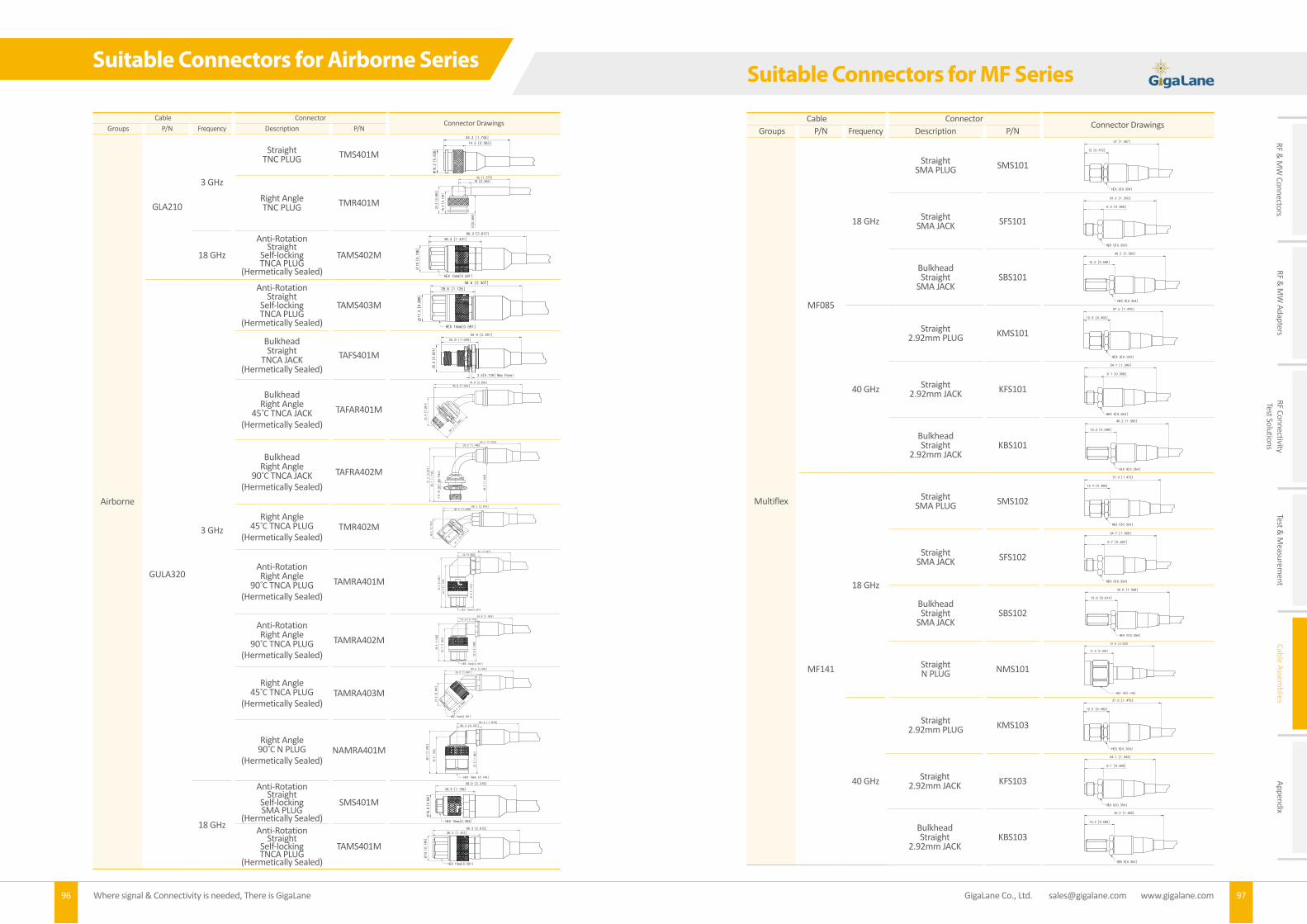
Where signal & Connectivity is needed, There is GigaLane96 97 GigaLane Co., Ltd. [email protected] www.gigalane.com
RF & M
W Connectors
RF & M
W Adapters
RF ConnectivityTest Solutions
Test & M
easurement
Cable Assemblies
Appendix
Suitable Connectors for Airborne Series
Cable ConnectorConnector Drawings
Groups P/N Frequency Description P/N
Airborne
GLA210
3 GHz
Straight TNC PLUG TMS401M
Right Angle TNC PLUG TMR401M
18 GHz
Anti-RotationStraight
Self-lockingTNCA PLUG
(Hermetically Sealed)
TAMS402M
GULA320
3 GHz
Anti-RotationStraight
Self-lockingTNCA PLUG
(Hermetically Sealed)
TAMS403M
BulkheadStraight
TNCA JACK(Hermetically Sealed)
TAFS401M
BulkheadRight Angle
45 C TNCA JACK(Hermetically Sealed)
TAFAR401M
BulkheadRight Angle
90 C TNCA JACK(Hermetically Sealed)
TAFRA402M
Right Angle 45 C TNCA PLUG
(Hermetically Sealed)TMR402M
Anti-RotationRight Angle
90 C TNCA PLUG(Hermetically Sealed)
TAMRA401M
Anti-RotationRight Angle
90 C TNCA PLUG(Hermetically Sealed)
TAMRA402M
Right Angle 45 C TNCA PLUG
(Hermetically Sealed)TAMRA403M
Right Angle 90 C N PLUG
(Hermetically Sealed)NAMRA401M
18 GHz
Anti-RotationStraight
Self-lockingSMA PLUG
(Hermetically Sealed)
SMS401M
Anti-RotationStraight
Self-lockingTNCA PLUG
(Hermetically Sealed)
TAMS401M
∅16.
2 [0
.638
]
14.3 [0.563]
44.3 [1.744]
G20SMC004M(구-TMS401M)
25.9 [1.020]
55.9 [2.201]
20.9 [0.821]
3.5[0.139] Max Panel
G24SFC001M(구-TAFS401M)
Cable ConnectorConnector Drawings
Groups P/N Frequency Description P/N
Multiflex
MF085
18 GHz
StraightSMA PLUG SMS101
StraightSMA JACK SFS101
BulkheadStraight
SMA JACKSBS101
40 GHz
Straight2.92mm PLUG KMS101
Straight2.92mm JACK KFS101
BulkheadStraight
2.92mm JACKKBS101
MF141
18 GHz
StraightSMA PLUG SMS102
StraightSMA JACK SFS102
BulkheadStraight
SMA JACKSBS102
StraightN PLUG NMS101
40 GHz
Straight2.92mm PLUG KMS103
Straight2.92mm JACK KFS103
BulkheadStraight
2.92mm JACKKBS103
12 [0.472]
37 [1.457]
HEX 9[0.354]
SMS1019.3 [0.366]
34.3 [1.350]
HEX 9[0.354]
SFS10115.2 [0.598]
40.2 [1.583]
HEX 9[0.354]
SBS10112.5 [0.492]
37.5 [1.476]
HEX 9[0.354]
KMS1019.1 [0.358]
34.1 [1.343]
HEX 9[0.354]
KFS101
15.2 [0.598]
40.2 [1.583]
HEX 9[0.354]
KBS10112.4 [0.488]
37.4 [1.472]
HEX 9[0.354]
SMS1029.7 [0.382]
34.7 [1.366]
HEX 9[0.354]
SFS10215.6 [0.614]
40.6 [1.598]
HEX 9[0.354]
SBS10221.8 [0.858]
51.8 [2.039]
HEX 19[0.748]
NMS10112.5 [0.492]
37.5 [1.476]
HEX 9[0.354]
KMS103
34.1 [1.343]
HEX 9[0.354]
9.1 [0.358]
KFS103
40.2 [1.583]
15.2 [0.598]
HEX 9[0.354]
KBS103
Suitable Connectors for MF Series

Where signal & Connectivity is needed, There is GigaLane98 99 GigaLane Co., Ltd. [email protected] www.gigalane.com
RF & M
W Connectors
RF & M
W Adapters
RF ConnectivityTest Solutions
Test & M
easurement
Cable Assemblies
Appendix
Cable ConnectorConnector Drawings
Groups P/N Frequency Description P/N
Semi-Rigid
SR085
18 GHz
StraightSMA PLUG SMS302
StraightSMA JACK SFS302
BulkheadStraight
SMA JACKSBS302
40 GHz
Straight2.92mm PLUG KMS301
Straight2.92mm JACK KFS301
BulkheadStraight
2.92mm JACKKBS301
SR141
18 GHz
StraightSMA PLUG SMS303
StraightSMA JACK SFS303
BulkheadStraight
SMA JACKSBS303
40 GHz
Straight2.92mm PLUG KMS303
Straight2.92mm JACK KFS303
BulkheadStraight
2.92mm JACKKBS303
Suitable Connectors for SR Series
Cable ConnectorConnector Drawings
Groups P/N Frequency Description P/N
Semi-Flexible(Handformable)
SF085
18 GHz
StraightSMA PLUG SMS302
StraightSMA JACK SFS302
BulkheadStraight
SMA JACKSBS302
40 GHz
Straight2.92mm PLUG KMS301
Straight2.92mm JACK KFS301
BulkheadStraight
2.92mm JACKKBS301
SF141
18 GHz
StraightSMA PLUG SMS303
StraightSMA JACK SFS303
BulkheadStraight
SMA JACKSBS303
40 GHz
Straight2.92mm PLUG KMS303
Straight2.92mm JACK KFS303
BulkheadStraight
2.92mm JACKKBS303
Suitable Connectors for SF Series
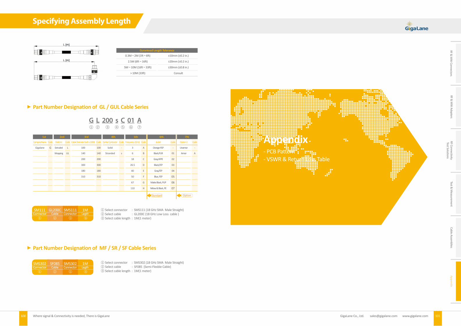
Where signal & Connectivity is needed, There is GigaLane100 101 GigaLane Co., Ltd. [email protected] www.gigalane.com
RF & M
W Connectors
RF & M
W Adapters
RF ConnectivityTest Solutions
Test & M
easurement
Cable Assemblies
Appendix
Guranteed Length Tolerance
0.3M ~ 2M (1ft ~ 6ft) ±10mm (±0.2 in.)
2.5M (6ft ~ 16ft) ±20mm (±0.2 in.)
5M ~ 10M (16ft ~ 33ft) ±30mm (±0.8 in.)
> 10M (33ft) Consult
Part Number Designation of GL / GUL Cable Series
1st 2nd 3rd 4th 5th 6th 7th
Company Name Code Dielctric Code Cable Diameter (inch x 1000) Code Center Conductor Code Frequency (GHz) Code Jacket Code Option 2 Code
Gigalane G Extruded L 100 100 Solid - 3 A Orange-FEP - Unarmor -
Wrapping UL 140 140 Stranded s 6 B Black,PUR 01 Armor A
200 200 18 C Gray,HFPE 02
300 300 26.5 D Black,FEP 03
180 180 40 E Gray,FEP 04
310 310 50 F Blue, FEP 05
67 G Matte Black, PUP 06
110 H Yellow & Black, PE 07
Standard Option
G L 200 s C 01 A① ② ③ ④ ⑤ ⑥ ⑦
① Select connector : SMS111 (18 GHz SMA Male Straight)② Select cable : GL200C (18 GHz Low Loss cable ) ③ Select cable length : 1M(1 meter)
Part Number Designation of MF / SR / SF Cable Series
① Select connector : SMS302 (18 GHz SMA Male Straight)② Select cable : SF085 (Semi-Flexble Cable)③ Select cable length : 1M(1 meter)
Specifying Assembly Length
SM111Connector
GL200CCable
SMS111Connector
1MLegth
① ② ① ③
SMS302Connector
SF085Cable
SMS302Connector
1MLegth
① ② ① ③
- PCB Pattern- VSWR & Return Loss Table
Appendix

Where signal & Connectivity is needed, There is GigaLane102 103 GigaLane Co., Ltd. [email protected] www.gigalane.com
RF & M
W Connectors
RF & M
W Adapters
RF ConnectivityTest Solutions
Test & M
easurement
Cable Assemblies
Appendix
Fig1 Fig2 Fig3
Fig4 Fig5 Fig6
Fig7 Fig8 Fig9
Fig10 Fig11 Fig12
Fig13 Fig14 Fig15
Fig16 Fig17 Fig18
PCB Pattern
VSWR, Return Loss, Trans. Loss, E Refl. Coeff., Transmitted/Reflected PowerVSWR VSWR
[dB]RETURN
LOSSTRANS.
LOSSVOLT. REFL.
POWER TRANS.
POWER REFL. VSWR VSWR
[dB]RETURN
LOSSTRANS.
LOSSVOLT. REFL.
POWER TRANS.
POWER REFL.
1.00 0.00 ∞ 0.000 0.000 100.000 0.000 1.84 5.30 10.58 0.398 0.296 91.3 8.7
1. 01 0.09 46.06 0.000 0.005 99.998 0.002 1.86 5.39 10.44 0.412 0.301 91.0 9.0
1.02 0.17 40.09 0.000 0.010 99.990 0.010 1.88 5.48 10.30 0.426 0.306 90.7 9.3
1.03 0.26 36.61 0.001 0.015 99.978 0.022 1.90 5.58 10.16 0.440 0.310 90.4 9.6
1.04 0.34 34.15 0.002 0.020 99.962 0.038 1.92 5.67 10.03 0.454 0.315 90.1 9.9
1.05 0.42 32.26 0.003 0.024 99.941 0.059 1.94 5.76 9.90 0.468 0.320 89.8 10.2
1.06 0.51 30.71 0.004 0.029 99.915 0.085 1.96 5.85 9.78 0.483 0.324 89.5 10.5
1.07 0.59 29.42 0.005 0.034 99.886 0.114 1.98 5.93 9.66 0.497 0.329 89.2 10.8
1.08 0.67 28.30 0.006 0.038 99.852 0.148 2.00 6.02 9.54 0.512 0.333 88.9 11.1
1.09 0.75 27.32 0.008 0.043 99.815 0.185 2.10 6.44 9.00 0.584 0.355 87.4 12.6
1.10 0.83 26.44 0.010 0.048 99.773 0.227 2.20 6.85 8.52 0.658 0.375 85.9 14.1
1.11 0.91 25.66 0.012 0.052 99.728 0.272 2.30 7.23 8.09 0.732 0.394 84.5 15.5
1.12 0.98 24.94 0.014 0.057 99.680 0.320 2.40 7.60 7.71 0.807 0.412 83.0 17.0
1.13 1.06 24.29 0.016 0.061 99.627 0.373 2.50 7.96 7.36 0.881 0.429 81.6 18.4
1.14 1.14 23.69 0.019 0.065 99.572 0.428 2.60 8.30 7.04 0.956 0.444 80.2 19.8
1.15 1.21 23.13 0.021 0.070 99.513 0.487 2.70 8.63 6.76 1.03 0.459 78.9 21.1
1.16 1.29 22.61 0.024 0.074 99.451 0.549 2.80 8.94 6.49 1.10 0.474 77.6 22.4
1.17 1.36 22.12 0.027 0.078 99.386 0.614 2.90 9.25 6.25 1.18 0.487 76.3 23.7
1.18 1.44 21.66 0.030 0.083 99.318 0.682 3.00 9.54 6.02 1.25 0.500 75.0 25.0
1.19 1.51 21.23 0.033 0.087 99.247 0.753 3.2 10.1 5.62 1.39 0.524 72.6 27.4
1.20 1.58 20.83 0.036 0.091 99.174 0.826 3.4 10.6 5.26 1.53 0.545 70.2 29.8
1.21 1.66 20.44 0.039 0.095 99.097 0.903 3.6 11.1 4.96 1.67 0.565 68.1 31.9
1.22 1.73 20.08 0.043 0.099 99.018 0.982 3.8 11.6 4.68 1.81 0.583 66.0 34.0
1.23 1.80 19.73 0.046 0.103 98.94 1.06 4.0 12.0 4.44 1.94 0.600 64.0 36.0
1.24 1.87 19.40 0.050 0.107 98.85 1.15 4.2 12.5 4.22 2.07 0.615 62.1 37.9
1.25 1.94 19.08 0.054 0.111 98.77 1.23 4.4 12.9 4.02 2.19 0.630 60.4 39.6
1.26 2.01 18.78 0.058 0.115 98.68 1.32 4.6 13.3 3.84 2.32 0.643 58.7 41.3
1.27 2.08 18.49 0.062 0.119 98.59 1.41 4.8 13.6 3.67 2.44 0.655 57.1 42.9
1.28 2.14 18.22 0.066 0.123 98.49 1.51 5.0 14.0 3.52 2.55 0.667 55.6 44.4
1.29 2.21 17.95 0.070 0.127 98.40 1.60 5.5 14.8 3.19 2.83 0.692 52.1 47.9
1.30 2.28 17.69 0.075 0.130 98.30 1.70 6.0 15.6 2.92 3.10 0.714 49.0 51.0
1.32 2.41 17.21 0.083 0.138 98.10 1.90 6.5 16.3 2.69 3.35 0.733 46.2 53.8
1.34 2.54 16.75 0.093 0.145 97.89 2.11 7.0 16.9 2.50 3.59 0.750 43.8 56.3
1.36 2.67 16.33 0.102 0.153 97.67 2.33 7.5 17.5 2.33 3.82 0.765 41.5 58.5
1.38 2.80 15.94 0.112 0.160 97.45 2.55 8.0 18.1 2.18 4.03 0.778 39.5 60.5
1.40 2.92 15.56 0.122 0.167 97.22 2.78 8.5 18.6 2.05 4.24 0.789 37.7 62.3
1.42 3.05 15.21 0.133 0.174 96.99 3.01 9.0 19.1 1.94 4.44 0.800 36.0 64.0
1.44 3.17 14.88 0.144 0.180 96.75 3.25 9.5 19.6 1.84 4.63 0.810 34.5 65.5
1.46 3.29 14.56 0.155 0.187 96.50 3.50 10.0 20.0 1.74 4.81 0.818 33.1 66.9
1.48 3.41 14.26 0.166 0.194 96.25 3.75 11.0 20.8 1.58 5.15 0.833 30.6 69.4
1.50 3.52 13.98 0.177 0.200 96.00 4.00 12.0 21.6 1.45 5.47 0.846 28.4 71.6
1.52 3.64 13.71 0.189 0.206 95.74 4.26 13.0 22.3 1.34 5.76 0.857 26.5 73.5
1.54 3.75 13.45 0.201 0.213 95.48 4.52 14.0 22.9 1.24 6.04 0.867 24.9 75.1
1.56 3.86 13.20 0.213 0.219 95.21 4.79 15.0 23.5 1.16 6.30 0.875 23.4 76.6
1.58 3.97 12.96 0.225 0.225 94.95 5.05 16.0 24.1 1.09 6.55 0.882 22.1 77.9
1.60 4.08 12.74 0.238 0.231 94.67 5.33 17.0 24.6 1.02 6.78 0.889 21.0 79.0
1.62 4.19 12.52 0.250 0.237 64.40 5.60 18.0 25.1 0.97 7.00 0.895 19.9 80.1
1.64 4.30 12.31 0.263 0.242 94.12 5.88 19.0 25.6 0.92 7.21 0.900 19.0 81.0
1.66 4.40 12.11 0.276 0.248 93.84 6.16 20.0 26.0 0.87 7.41 0.905 18.1 81.9
1.68 4.51 11.91 0.289 0.254 93.56 6.44 22.0 26.8 0.79 7.79 0.913 16.6 83.4
1.70 4.61 11.73 0.302 0.259 93.28 6.72 24.0 27.6 0.72 8.14 0.920 15.4 84.6
1.72 4.71 11.54 0.315 0.265 92.99 7.01 26.0 28.3 0.67 8.46 0.926 14.3 85.7
1.74 4.81 11.37 0.329 0.270 92.71 7.29 28.0 28.9 0.62 8.76 0.931 13.3 86.7
1.76 4.91 11.20 0.342 0.275 92.42 7.58 30.0 29.5 0.58 9.04 0.935 12.5 87.5
1.78 5.01 11.04 0.356 0.281 29.13 7.87 35.0 30.9 0.50 9.66 0.944 10.8 89.2
1.80 5.11 10.88 0.370 0.286 91.84 8.16 40.0 32.0 0.43 10.21 0.951 9.5 90.5
1.82 5.20 10.73 0.384 0.291 91.54 8.46 50.0 34.0 0.35 11.14 0.961 7.7 92.3
VSWR & Return Loss Table

www.gigalane.com
Where Signal & Connectivity is needed,There is GigaLane.