rianov...rianov ™ operator’s manual page 3 of 19 use of this manual prior to use or installation...
TRANSCRIPT

RIANOV Optical Ranging Device
SOLO
Operator’s Manual
10 November 2012
™

RIANOV ™ Operator’s Manual Page 2 of 19
Table of Contents Section 1 - Use of this Manual 3
Warranty and Service 3 Technical Specifications 4 Product Description 4
Section 2 - System Contents 5 Section 3 - Replacing the Battery 6 Section 4 - Installing the RIANOV ™on your Scope 7 Section 5 - Screen Navigation KEYPAD & DISPLAY 8 CONFIGURATION 9 Section 6 - Setup of the RIANOV ™Optical Ranging Device WEAPON 10 ENVIRONMENT / MODE 11 SYSTEM / RATIO 12 CALIBRATION 13 Section 7 - Use of the RIANOV ™Optical Ranging Device
Measure Slope + MILS Mode - Determining Range 14 Measure Slope + DtT Mode - Determining Range 14 Enter Slope & MILS Mode - Determining Range 15 Enter Slope & DtT Mode - Determining Range 15
Error Screen 15 Inputting Wind Conditions 16 Changing Units/Settings / Definition of Terms 17 Changing Numerical Values 18 Ballistics Calculations 19

RIANOV ™ Operator’s Manual Page 3 of 19
USE OF THIS MANUAL Prior to use or installation of the RIANOV ™ Optical Ranging Device, read this
manual in its entirety and make sure you are familiar with the use and care requirements.
It is important that you, and all users of your RIANOV ™ Optical Ranging
Device, understand the principles of its operations. Keep this manual with the
RIANOV ™ Optical Ranging Device, and transfer it to any future owner. If you
require additional copies of this manual, a copy can be downloaded from our web site.
The RIANOV ™ Optical Ranging Device is not a safety device and normal
firearm safety procedures should be maintained during the installation and usage of the
RIANOV ™ Optical Ranging Device. Failure to follow safety guidelines may
result in bodily injury or death.
WARRANTY (LIMITED) AND SERVICE ZRF, LLC, warrants that this product was manufactured free of defects in materials and workmanship and for a period of twelve months from the date of purchase by the original owner, ZRF, LLC agrees to correct any defect for the original purchaser by repair or replacement with the same or comparable model, at the sole discretion of ZRF, LLC. The warranty does not cover abuse, misuse, lost items, batteries, and consequential and incidental damages are not recoverable under this warranty. Some states do not allow the exclusion or limitation of incidental or consequential damages, so the above limitation or exclusion may not apply to you. This written warranty is the only warranty provided and any implied warranty of merchantability or fitness is limited to the same twelve month period. Technical specifications are subject to change without notice. If your RIANOV ™ Optical Ranging Device requires service, whether made under warranty or not, please contact ZRF, LLC for instructions on how to have your RIANOV ™ Optical Ranging Device repaired.
ZRF, LLC P.O. Box 81644 Atlanta, GA 30366 (770) 657-7855 www.RIANOV.com

RIANOV ™ Operator’s Manual Page 4 of 19
Technical Specifications RIANOV ™ Optical Ranging Device - SOLO Weight: 2.8 oz. (80 grams) Display: LCD with Graphics - 16 Character x 3 Row User Interface: 5 Button Keypad Operating Temperature Range: -13°F to 140°F (-25°C to 60°C) Altitude Range: -1,600ft to 29,600ft (-300m to 9,000m) Barometric Pressure Resolution: 0.01InHg Optical Ranging: >3,000 Yards Angular Ranges: ±73° Slope (Look Angle) ±80° CANT Angular Resolution: <0.1° Battery Type: CR-123 Battery Life: 2 Years (based on average use case)
Product Description The RIANOV ™ Optical Ranging Device - SOLO is a ballistic calculating device that works in conjunction with your rifle scope, regardless of manufacturer or reticle marking type, thereby making all scopes Range Finding Scopes and at any magnification the user’s scope can be set. The RIANOV ™SOLO, which easily mounts to your scope, calculates the Range to your intended target and provides accurate real-time calculated ballistic solutions - based on the JBM Ballistics solver - for Elevation and Windage adjustments with the push of a button and the aiming of your rifle. The RIANOV ™ SOLO internal sensors monitor and compensate for barometric pressure, temperature, CANT and look angle (Slope) in the ballistic solutions provided, allowing the user to remain focused down range and no longer worry about offset charts or calculating adjustment factors. The RIANOV ™ SOLO can be installed in under five (5) minutes to nearly any scope (with Optional Scope Mount Kit) and it does not interfere with the zero settings of the rifle, making getting started user friendly.

RIANOV ™ Operator’s Manual Page 5 of 19
Section 2 -
Figure 2.1
System Contents The RIANOV ™ SOLO Kit, shown above in Figure 2.1, contains the following:
1 - RIANOV ™ SOLO Optical Ranging Device 1 - CR123A Lithium Battery (installed – not shown) 1 - RIANOV ™ SOLO Optical Ranging Device Quick Start Guide (not shown)
Also shown is the SOLO Scope Mount Kit:
1 - Scope Mount Top 1 - Scope Mount bottom 1 - Long Arm Hex Key (not shown) 8 - M3x6mm Screws (2 spares – not shown)
RIANOV™
SOLO Scope Mount Bottom
M3x6mm Screws
SOLO Scope Mount Top

RIANOV ™ Operator’s Manual Page 6 of 19
Section 3 - Replacing the battery
Figure 3.1
Figure 3.2
Remove the two (2) M3x6mm screws and
the Battery Cover/Battery Seal as shown
in Figure 3.1. Remove the old battery,
dispose of it properly and replace it with a
new CR123A Battery.
Align the battery with the battery
compartment between the battery
contacts and press the battery into the
unit. Make sure the positive terminal of
the battery is to the right (starboard side
for you naval types). The
RIANOV™ SOLO unit will not
operate with the battery installed
backwards.
Do not attempt to modify the battery
contacts. Doing so will void the warranty.
Align the Battery Cover and the two (2)
M3x6mm screws and tighten as shown in
Figure 3.2.
CR123A batteries are commonly used in
flashlights and cameras.
PRIOR TO INSTALLING YOUR RIANOV ™ TO
YOUR RIFLE, MAKE CERTAIN THAT IT IS UNLOADED.
REFER TO YOUR FIREARM OWNER’S MANUAL TO
ENSURE THE FIREARM IS SAFE

RIANOV ™ Operator’s Manual Page 7 of 19
Section 4 - Installing on your Scope (Optional Scope Mount Kit)
Figure 4.1
Figure 4.2
Figure 4.3
Figure 4.4
Attach the Top half of the Scope Mount Kit to the Cover of the
SOLO as shown in Figure 4.1 & 4.2 using two of the M3x6mm
screws that are with the Optional Scope Mount Kit.
Position the Scope Mount behind the elevation turret on your
scope at the desired position as shown in Figure 4.3.
Attach the Bottom half of the Scope Mount Kit to the Top half of
the Scope Mount Kit as shown in Figure 4.3 & 4.4 using two of
the M3x6mm screws that are with the Optional Scope Mount
Kit.
To ensure that you can view the SOLO display, use the
appropriate holes when attaching the Top half of the Scope
Mount Kit to the Cover of the SOLO as shown in Figure 4.1 & 4.2
such that the display is above the elevation turret as shown in
Figure 4.5.
PRIOR TO INSTALLING YOUR RIANOV ™ TO
YOUR RIFLE, MAKE CERTAIN THAT IT IS UNLOADED.
REFER TO YOUR FIREARM OWNER’S MANUAL TO
ENSURE THE FIREARM IS SAFE
Figure 4.5

RIANOV ™ Operator’s Manual Page 8 of 19
Section 5 – Screen Navigation Keypad & Display
Figure 5.1
Keypad – There are two ways to use the buttons on the keypad - Press and Release – P/R - Press the button and release in less than 1 second Press and Hold – P/H - Press the button and hold for more than 1 second Power: If the RIANOV ™ SOLO unit is off, P/R this button to turn the device on If the RIANOV ™ is on, P/R this button to initiate a Ranging operation. You will be prompted for different inputs based on the Ranging Mode of the RIANOV ™ SOLO unit (see pages 14-15 for more information). P/H this button to move to the CONFIGURATION Screen
Arrow Buttons: Use these four (4) buttons to navigate (move) up/down/right/left on the screen and to increase/decrease
values
The RIANOV ™ SOLO unit shown in figure 5.1 is displaying the HOME Screen. This is the screen that will be displayed during most of the operation of the device. There are several items that can be modified from this screen and you can navigate to the other screens from the HOME Screen. To navigate around this screen press and release the Right or Left Arrow Button that corresponds to the direction you wish to navigate (move). To edit fields on this screen, navigate to the field you wish to change and press the Up or Down Arrow Button to change the value of the field you are on.
Elevation Adjustment Units
Wind Speed Units
Wind Speed
Wind Direction- Going To
Range to Target Units
Range to Target
Elevation Adjustment
Windage Adjustment
Windage Adjustment Units
Each of the Display Fields above has its own purpose in determining the firing solution and is explained in detail in the sections below
Mode
Slope Angle
Speed
Cant Angle
POWER Button

RIANOV ™ Operator’s Manual Page 9 of 19
In this manual the screen layouts will be displayed as shown below in the normal 3 rows by 16 character format. The screen layout shown below matches the information as shown in Figure 5.1.
Figure 5.1A Special characters – There is one special character that appears on most screens. The “HOME” characters, as shown below in Figure5.1B.
Figure 5.1B
Any screen on which you find this special character will redirect you as follows: HOME - - return you to the HOME Screen You can move to the CONFIGURATION Screen, as shown in Figure 5.2 Screen by pressing and holding (P/H) the POWER Button for one (1) second while on any screen. From the CONFIGURATION Screen you will be able to access the following screens: WEAPON ENVIRONMENT MODE SYSTEM RATIO SETUP CALIBRATION
Figure 5.2

RIANOV ™ Operator’s Manual Page 10 of 19
Section 6 - Setup of the RIANOV ™ Viewing the WEAPON Screen - To view the WEAPON Screen on your RIANOV ™ SOLO unit, navigate to the “WEAPON” field on the CONFIGURATION
Screen (see Figure 5.2) and P/R the POWER Button. You will be shown the current option for entering data.
TWIST RATE Rate of twist inside the barrel
TWIST DIRECTION Direction of the twist inside the barrel
CALIBER Caliber of the weapon
BC Ballistic Coefficient of the bullet
WEIGHT Weight of the bullet
LENGTH Length of the bullet
RETICLE Type of reticle marking inside the scope
SCPHEIGHT Distance between the scope centerline and the barrel centerline
SCPOFFSET Distance the scope is offset (left (-) or right (+)) from the barrel centerline
ELEV* The number of clicks per MIL ( or MOA/IPHY) of your elevation turret
WIND* The number of clicks per MIL (or MOA/IPHY) of your windage turret
MUZ VEL The muzzle velocity of your bullet
MVCORR§ The amount your muzzle velocity varies with changing temperature
CHRONO DIST The distance to your chronograph (enter 0 if you are estimating MUZ VEL)
ELEV ADD¤ The amount you currently have dialed into your elevation turret
RANGE The range at which your weapon is zeroed
TEMP The temperature at which your weapon is zeroed
BP The barometric pressure at which your weapon is zeroed
HUMD The humidity at which your weapon is zeroed
BEARING The bearing at which your weapon is zeroed
LATITUDE The latitude at which your weapon is zeroed
To select an option or enter data in one of these fields, navigate to the desired field and P/R the POWER Button to enter edit
mode. Use the Right Arrow or Left Arrow Button to move the value you want to change and use the Up Arrow or Down Arrow
Buttons to change the value. When you have completed making all of the changes in a field P/R the POWER Button to exit
edit mode. Complete these steps for all fields that you want to change and navigate to the “HOME Icon” on the top line of
the screen, P/R the POWER Button to return to the HOME Screen.
*- Entered as number of clicks per MIL (for example – a ¼ MIL per Click is entered as 4.000 Clicks / MIL). This is also valid for
MOA/IPHY or other units.
§ - MVCORR – By taking Chronograph data of the same ammunition fired from the same rifle at different temperatures (but
at the same or nearly the same Barometric Pressure) you can easily determine your MVCORR – see the example below:
¤ - ELEV ADD is used to have the required elevation adjustment display by the RIANOV ™ SOLO unit automatically
corrected for targets at a given distance. After you have dialed-in a given value on your elevation turret and entered in the
same value into the SOLO, the solution you are provided is now a hold over or hold under. Make sure you set this value to
0.00 if you return your elevation turret to its zero point.
Case 1) MV1 = 2558 Feet per Second and Temp1 = 15 °F
Case 2) MV2 = 2600 Feet per Second and Temp2 = 85 °F
(MV2-MV1)/(Temp2-Temp1) = (2600-2558)/(85-15) = 42/70 = 0.60 Feet per Second / °F
}
The larger the temperature
difference the better
RIANOV ™ Operator’s Manual Page 11 of 19
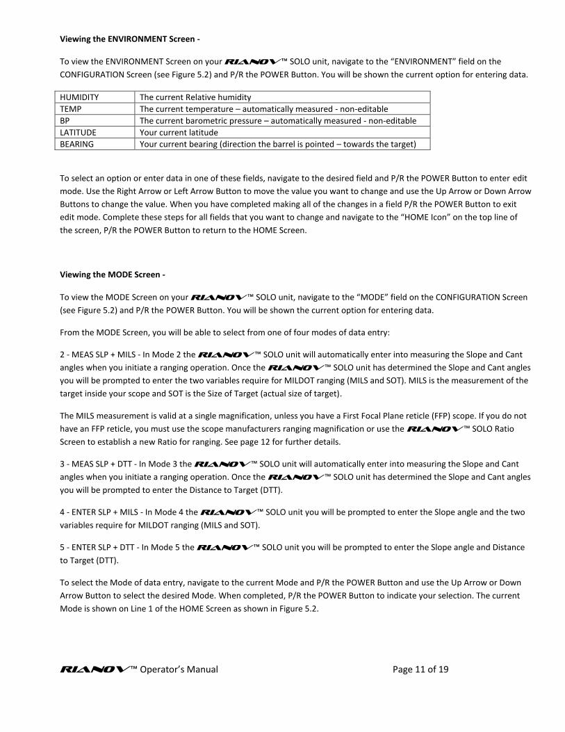
Viewing the ENVIRONMENT Screen - To view the ENVIRONMENT Screen on your RIANOV ™ SOLO unit, navigate to the “ENVIRONMENT” field on the
CONFIGURATION Screen (see Figure 5.2) and P/R the POWER Button. You will be shown the current option for entering data.
HUMIDITY The current Relative humidity
TEMP The current temperature – automatically measured - non-editable
BP The current barometric pressure – automatically measured - non-editable
LATITUDE Your current latitude
BEARING Your current bearing (direction the barrel is pointed – towards the target)
To select an option or enter data in one of these fields, navigate to the desired field and P/R the POWER Button to enter edit
mode. Use the Right Arrow or Left Arrow Button to move the value you want to change and use the Up Arrow or Down Arrow
Buttons to change the value. When you have completed making all of the changes in a field P/R the POWER Button to exit
edit mode. Complete these steps for all fields that you want to change and navigate to the “HOME Icon” on the top line of
the screen, P/R the POWER Button to return to the HOME Screen.
Viewing the MODE Screen - To view the MODE Screen on your RIANOV ™ SOLO unit, navigate to the “MODE” field on the CONFIGURATION Screen
(see Figure 5.2) and P/R the POWER Button. You will be shown the current option for entering data.
From the MODE Screen, you will be able to select from one of four modes of data entry:
2 - MEAS SLP + MILS - In Mode 2 the RIANOV ™ SOLO unit will automatically enter into measuring the Slope and Cant
angles when you initiate a ranging operation. Once the RIANOV ™ SOLO unit has determined the Slope and Cant angles
you will be prompted to enter the two variables require for MILDOT ranging (MILS and SOT). MILS is the measurement of the
target inside your scope and SOT is the Size of Target (actual size of target).
The MILS measurement is valid at a single magnification, unless you have a First Focal Plane reticle (FFP) scope. If you do not
have an FFP reticle, you must use the scope manufacturers ranging magnification or use the RIANOV ™ SOLO Ratio
Screen to establish a new Ratio for ranging. See page 12 for further details.
3 - MEAS SLP + DTT - In Mode 3 the RIANOV ™ SOLO unit will automatically enter into measuring the Slope and Cant
angles when you initiate a ranging operation. Once the RIANOV ™ SOLO unit has determined the Slope and Cant angles
you will be prompted to enter the Distance to Target (DTT).
4 - ENTER SLP + MILS - In Mode 4 the RIANOV ™ SOLO unit you will be prompted to enter the Slope angle and the two
variables require for MILDOT ranging (MILS and SOT).
5 - ENTER SLP + DTT - In Mode 5 the RIANOV ™ SOLO unit you will be prompted to enter the Slope angle and Distance
to Target (DTT).
To select the Mode of data entry, navigate to the current Mode and P/R the POWER Button and use the Up Arrow or Down
Arrow Button to select the desired Mode. When completed, P/R the POWER Button to indicate your selection. The current
Mode is shown on Line 1 of the HOME Screen as shown in Figure 5.2.

RIANOV ™ Operator’s Manual Page 12 of 19
Viewing the SYSTEM Screen - To view the SYSTEM Screen on your RIANOV ™ SOLO unit, navigate to the “SYSTEM” field on the CONFIGURATION
Screen (see Figure 5.2) and P/R the POWER Button. You will be shown the current option for entering data.
AUTO OFF Time in seconds to turn the unit off after the last key press
DELAY TMR Time in seconds for the delay before starting a Slope / Cant measurement
BACKGROUND Color of the background
BRIGHTNESS Screen brightness level
BATTERY Percent battery life remaining - non-editable
SERNUM Unit serial number - non-editable
To select an option or enter data in one of these fields, navigate to the desired field and P/R the POWER Button to enter edit
mode. Use the Right Arrow or Left Arrow Button to move the value you want to change and use the Up Arrow or Down Arrow
Buttons to change the value. When you have completed making all of the changes in a field P/R the POWER Button to exit
edit mode. Complete these steps for all fields that you want to change and navigate to the “HOME Icon” on the top line of
the screen, P/R the POWER Button to return to the HOME Screen.
-- NOTE -- The longer the Display remains on after each button press will reduce the battery life of the RIANOV ™ SOLO unit. The battery life of 2 years is based on a 30 seconds Display On Time setting and the average use of 2 reads/hour, 6 hours/day and 2 days/week. -- NOTE -- If you set the brightness low for low light conditions and forget to change back to a daylight setting, you may have difficulty reading the display in daylight conditions.
Viewing the RATIO Screen - To view the RATIO Screen on your RIANOV ™ SOLO unit, navigate to the “RATIO” field on the CONFIGURATION Screen
(see Figure 5.2) and P/R the POWER Button. You will be shown the current option for entering data. You will need to adjust
these values to match the scope you will be mounting to the RIANOV ™ SOLO unit. The information entered here will
be used in range estimating using MILDOT /MOA/IPHY techniques.
RANGE Distance to the target being measured
OBJSIZE Size of the object being measured
DIVISION User defined parameter – see below Fig 6.1
RATIO System Parameter - non-editable
RNG MAG Magnification being used
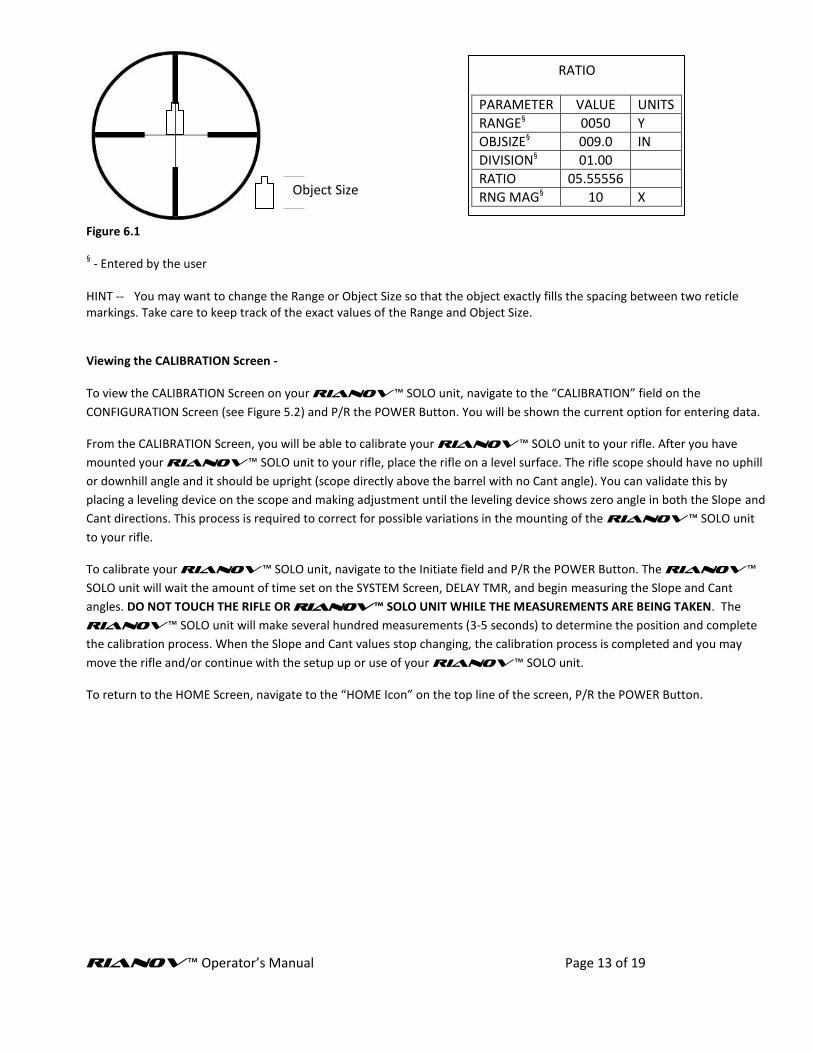
You will now need to complete the following steps: 1) Place a known sized object at a known range from your scope. A large object (9”-36”) at a close range (less than 100 yards) on a level surface (Slope close to 0°) works best. 2) Enter the Range and Object Size in the fields as shown on the RATIO Screen. Be very accurate with these values, as this is the basis for all future range estimating. For this example we will use 9” as the value for Object Size and 50 yards as the value for Range. 3) Look through your scope and determine the DIVISIONS you consider this object to be, as shown in Figure 6.13. You can use any value you like, just remember this for future use. For this example we will use 1 as the value for Divisions. 4) Enter the selected value in the Divisions field. Once you have entered each of the three values, the Ratio will automatically calculate and display the value based on your inputs, replacing the default value. For this example the new Ratio value would be 5.55556.
RIANOV ™ Operator’s Manual Page 13 of 19
Figure 6.1 § - Entered by the user
HINT -- You may want to change the Range or Object Size so that the object exactly fills the spacing between two reticle markings. Take care to keep track of the exact values of the Range and Object Size.
Viewing the CALIBRATION Screen - To view the CALIBRATION Screen on your RIANOV ™ SOLO unit, navigate to the “CALIBRATION” field on the
CONFIGURATION Screen (see Figure 5.2) and P/R the POWER Button. You will be shown the current option for entering data.
From the CALIBRATION Screen, you will be able to calibrate your RIANOV ™ SOLO unit to your rifle. After you have
mounted your RIANOV ™ SOLO unit to your rifle, place the rifle on a level surface. The rifle scope should have no uphill
or downhill angle and it should be upright (scope directly above the barrel with no Cant angle). You can validate this by
placing a leveling device on the scope and making adjustment until the leveling device shows zero angle in both the Slope and
Cant directions. This process is required to correct for possible variations in the mounting of the RIANOV ™ SOLO unit
to your rifle.
To calibrate your RIANOV ™ SOLO unit, navigate to the Initiate field and P/R the POWER Button. The RIANOV ™
SOLO unit will wait the amount of time set on the SYSTEM Screen, DELAY TMR, and begin measuring the Slope and Cant
angles. DO NOT TOUCH THE RIFLE OR RIANOV ™ SOLO UNIT WHILE THE MEASUREMENTS ARE BEING TAKEN. The
RIANOV ™ SOLO unit will make several hundred measurements (3-5 seconds) to determine the position and complete
the calibration process. When the Slope and Cant values stop changing, the calibration process is completed and you may
move the rifle and/or continue with the setup up or use of your RIANOV ™ SOLO unit.
To return to the HOME Screen, navigate to the “HOME Icon” on the top line of the screen, P/R the POWER Button.
Object Size
RATIO
PARAMETER VALUE UNITS
RANGE§ 0050 Y
OBJSIZE§ 009.0 IN
DIVISION§ 01.00
RATIO 05.55556
RNG MAG§ 10 X
RIANOV ™ Operator’s Manual Page 14 of 19
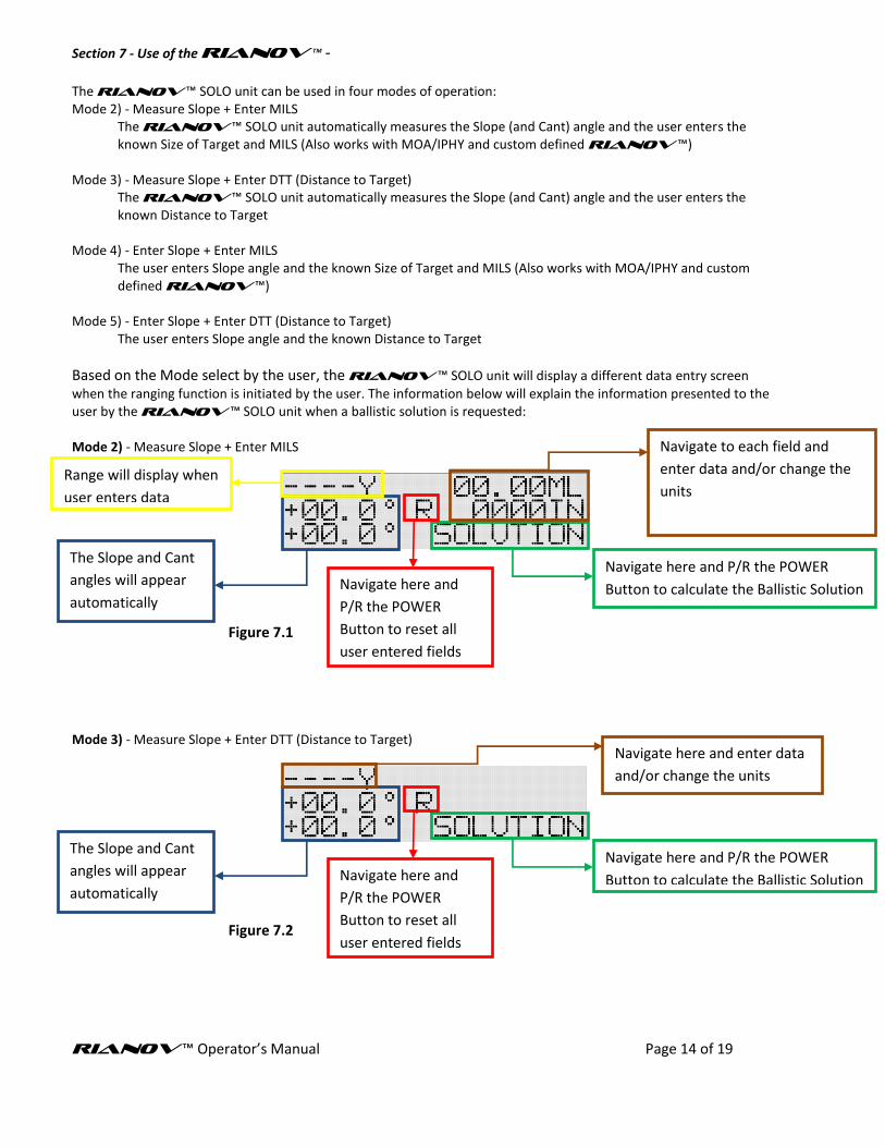
Section 7 - Use of the RIANOV ™ - The RIANOV ™ SOLO unit can be used in four modes of operation: Mode 2) - Measure Slope + Enter MILS
The RIANOV ™ SOLO unit automatically measures the Slope (and Cant) angle and the user enters the known Size of Target and MILS (Also works with MOA/IPHY and custom defined RIANOV ™)
Mode 3) - Measure Slope + Enter DTT (Distance to Target)
The RIANOV ™ SOLO unit automatically measures the Slope (and Cant) angle and the user enters the known Distance to Target
Mode 4) - Enter Slope + Enter MILS
The user enters Slope angle and the known Size of Target and MILS (Also works with MOA/IPHY and custom defined RIANOV ™)
Mode 5) - Enter Slope + Enter DTT (Distance to Target)
The user enters Slope angle and the known Distance to Target
Based on the Mode select by the user, the RIANOV ™ SOLO unit will display a different data entry screen
when the ranging function is initiated by the user. The information below will explain the information presented to the user by the RIANOV ™ SOLO unit when a ballistic solution is requested: Mode 2) - Measure Slope + Enter MILS
Figure 7.1 Mode 3) - Measure Slope + Enter DTT (Distance to Target)
Figure 7.2
Navigate here and P/R the POWER
Button to calculate the Ballistic Solution
The Slope and Cant
angles will appear
automatically
Navigate to each field and
enter data and/or change the
units
Navigate here and P/R the POWER
Button to calculate the Ballistic Solution
The Slope and Cant
angles will appear
automatically
Navigate here and
P/R the POWER
Button to reset all
user entered fields
Navigate here and
P/R the POWER
Button to reset all
user entered fields
Range will display when
user enters data
Navigate here and enter data
and/or change the units

RIANOV ™ Operator’s Manual Page 15 of 19
Mode 4) - Enter Slope + Enter MIL
Figure 7.3 Mode 5) - Enter Slope + Enter DTT (Distance to Target)
Figure 7.4
Error Screen If during the usage of your RIANOV ™ SOLO unit, you range a target that is outside of the effective range of your defined Weapon System at the current environmental conditions, such that the velocity of the round goes below 0.4*SoS (Speed of Sound) before reaching the target, the Home Screen will appear as shown in Figure 7.5. This screen may also appear if you have yet to complete adding all of the parameters required to fully define a Weapon System or if you measure or input an invalid Slope or Cant angle. Please see Page 19 for the complete list of information required.
Figure 7.5
Navigate here and P/R the POWER
Button to calculate the Ballistic Solution
Navigate to this
field and enter data
Navigate to each field and
enter data and/or change the
units
Navigate here and
P/R the POWER
Button to reset all
user entered fields
Navigate here and P/R the POWER
Button to calculate the Ballistic Solution
Navigate to this
field and enter data
Navigate here and
P/R the POWER
Button to reset all
user entered fields
Range will display when
user enters data
Navigate here and enter data
and/or change the units

RIANOV ™ Operator’s Manual Page 16 of 19
Inputting Wind Conditions To input the current wind conditions navigate to either the Wind Speed or Wind Direction field on the HOME Screen using the Left Arrow or Right Arrow Button. Once on the field you wish to change, use the Up Arrow or Down Arrow Button to change the value shown. The Direction field is selected by numerical values ranging from 1 to 12, where each value represents the numbers on an analog clock and is the direction the wind is going to. The Wind Speed field is where you indicate the magnitude of the wind with unit options of MH (Miles Per hour), MS (Meter Per Second) and FS (Feet Per Second). The RIANOV™ user interface takes into consideration the requirements of shooting in real world conditions and is designed to allow inputs to be added and results displayed with sufficient time remaining to allow the user to make the adjustments necessary and take the shot before the conditions change. From this screen, as shown in Figure 7.6, you will be able to quickly input the changing wind conditions and have the results displayed with enough time remaining to make the adjustments before the wind changes. The Windage adjustment shown is the combined Windage adjustment from all sources (Spin Drift, Coriolis Effect, Wind, etc). You may also see changes in the Elevation Adjustment as you change the Wind Speed and Wind Direction. This change is due to the impact of Aerodynamic Jump which is a function of Wind Speed and Wind Direction.
Figure 7.6 * - On the HOME Screen, navigation is with the Right Arrow and Left Arrow Buttons. To change the value, use the Up Arrow and Down Arrow Button.
Navigate here and enter data
and/or change the units. *

RIANOV ™ Operator’s Manual Page 17 of 19
Changing Units/Setting Table 7.1
List of Terms
Term Definition
CK Clicks
CM Centimeters
FC Feet Per Second /°C
FF Feet Per Second /°F
FT Feet
FS Feet Per Second
GM Grams
GR Grains
HUMD Humidity
IN Inches
PH Inches / Hundred Yards
HG Inches Mercury
KP Kilopascals
LT Left
M Meters
MA Minutes of Angle*
MB Millibars
MC Meter Per Second /°C
MF Meter Per Second /°F
ML Miliradians
MH Miles Per Hour
MS Meter Per Second
N North
RT Right
RV RIANOV Units
S South
SEC Seconds
Y Yards
°F Fahrenheit
°C Celsius
The RIANOV ™ SOLO unit is highly versatile in many ways. It can be used with any caliber rifle; any scope type and it can be used at any magnification that your scope can be set to. Additionally, the RIANOV ™ SOLO unit can display its input and output values in many different units to meet the needs of the individual shooter (See Table 7.1). Below is a table of parameters and their associated unit options (See Table 7.2). The units can be easily changed by navigating to the units’ field and P/R the POWER Button. With the use of the Up Arrow and Down Arrow Buttons, you can page through the options available for the units’ field you have selected to modify. As you page through the unit options the value associated with the units’ field will be converted to show the new value with the new units. When you have reached the units you would like to show on the display for this units’ field, simply P/R the POWER Button. * - Also known as Minutes of Arc
Definition of Terms – Caliber – Diameter of the bullet in Inches or CM Bullet Weight – Weight of bullet in Grains or Grams Bullet Length – Length of bullet in Inches or CM Drag Function – A drag function (or G function) provides the forces on a standard bullet for which the drag function was derived. A bullet's ballistic coefficient then relates the drag on any bullet to that of the standard bullet. Ballistic Coefficient – The ballistic coefficient represents the ratio of the drag of the standard (e.g. G1 standard bullet) bullet to that of the bullet you are shooting. A ballistic coefficient of 0.100 means that your bullet has 10 times the drag of the standard bullet. Zero Range – The range at which you wish the bullet to cross the line of sight. Zero BP – The Barometric Pressure when the Zero was set. Zero Temp – The temperature when the Zero was set. Zero Humd – The humidity when the Zero was set. Distance to Chronograph – The distance from the muzzle of the firearm to the chronograph used for muzzle velocity measurements. If the muzzle velocity is estimated, leave the 000 for this value. Muzzle Velocity – The velocity of the bullet as either (1) measured at some distance from the muzzle or (2) as estimated from reloading data in FPS, MPH or MPS. The RIANOV ™ SOLO unit can correct for the distance to chronograph. (The velocity lost traveling to the chronograph.) Chronograph – A device used to measure the velocity of a bullet.

RIANOV ™ Operator’s Manual Page 18 of 19
Table 7.2
Default Units Optional Units/Settings
Barometric Pressure HG MB KP
Barrel Twist Direction RT (RIGHT) LT (LEFT)
Barrel Twist Rate IN/TWIST CM/TWIST
Bearing ° (Degrees)
Bullet Caliber IN CM MM
Bullet Length IN CM MM
Bullet Weight GR GM
CANT ° (Degrees)
Clicks - Elevation CK / MA CK / ML CK / PH
Clicks - Windage CK / MA CK / ML CK / PH
Distance to Chronograph FT Y M
Drag Function G1 G2 G5 G6 G7 G8 GI GL RA
Drop MA (MOA) ML (MIL) CK IN PH RV
Elevation Adjustment MA (MOA) ML (MIL) CK IN PH RV
Humidity 1-30% 30-40% 40-60% 60-70% 70-99%
Latitude ° (Degrees)
Latitude Magnitude N S
Muzzle Velocity FS MS MH
Muzzle Velocity Correction FF FC MF MC
Range Y M
Reticle Type ML (Milliradians) MA (MOA) PH RV
Scope Height IN CM
Scope Offset IN CM
Size of Target (SoT) IN FT Y CM M
Slope ° (Degrees)
Temperature °F °C
Wind Speed MH FS MS
Zero Range Y M
Zero Barometric Pressure HG MBAR KPA
Zero Temperature °F °C
Changing Numerical Values To change numeric values on any screen (except the HOME Screen) on your RIANOV ™ SOLO unit,
navigate to the field you want to change and P/R the POWER Button. Use the Up Arrow Button or Down
Arrow Button to change the value. When you have reached the desired numeric value in one place and you
want to move to a different place, press the Right Arrow button or Left Arrow Button until you reach the
desired place. Complete these steps until all places have the desired values. P/R the POWER Button to exit
editing in this field. Depending on the field changed, this may initiate a recalculation of the Range and
Ballistic solution.

RIANOV ™ Operator’s Manual Page 19 of 19
Ballistics Calculations
This manual and all of its contents are the sole property of ZRF, LLC and are protected under US Copyright laws. RIANOV and the stylized RIANOV are trademarks of ZRF, LLC.
The RIANOV™ SOLO unit has an internal Ballistics Calculator, utilizing on the JBM Ballistics solver, for the determination of a ballistics solutions based on rifle, scope and ammunition parameters entered and selected by the user. If you are in need of certain parameters to complete the required fields for the RIANOV™ SOLO unit, specifically ammunition parameters (including bullet length), review the information at www.jbmballistics.com for your selected ammunition type. There is a large library of bullet types to select from and all required information is available there. The program will run, and display the ballistic solution, when the minimum fields are completed. A ballistic solution will be displayed solely from calculated values from the user entries. The user assumes all risk for the data entered. Additionally, with a few onetime data entries, your ballistic solution will include the effects of Spin Drift, the aerodynamic impact of a spin stabilized projectile and Aerodynamic Jump, the impact to elevation adjustment due to a cross wind. And for long range shots that need that extra bit of accuracy, correction for Coriolis Effects (Horizontal and Vertical) can be added by inputting two simple data points on the Environment Screen. The RIANOV™ SOLO unit offers you the levels of data input needed to give you the confidence that your Ballistic Solution is as accurate as you need it to be and calculates to higher precision with the addition of the optional variable inputs.
The RIANOV™ SOLO unit requires the following data fields to be completed in order to generate a ballistic solution: WEAPON Screen: Twist Rate – Barrel Twist Rate
Twist Dir – Barrel Twist Direction Caliber
BC – Ballistic Coefficient Drag Function Weight – Bullet Weight Length – Bullet Length Reticle – Reticle Type SCPHeight – Scope Height SCPOffset – Scope Offset Elev Wind Muz Vel – Muzzle Velocity MV Corr – Muzzle Velocity Correction Factor (the muzzle velocity temperature correction factor for your ammunition) Distance to Chronograph Elev Add
Range – Zero Range Temp – Zero Temperature BP – Zero Barometric Pressure Humd – Zero Humidity
Bearing – Zero Bearing (the direction your rifle was pointed when you zeroed) Latitude – Zero Latitude (your position north or south of the equator when you zeroed)
ENVIRONMENT Screen:
Humidity – Current Humidity Latitude – Current Latitude (the position north or south of the equator) Bearing – Current Bearing (the direction your rifle is pointed)
RATIO Screen: RNG MAG – Ranging Magnification