riggermeister - entertainmentrigging.com guide.pdf · rigging operational guidelines should also be...
TRANSCRIPT
RIGGERMEISTER
a division of , Inc. ! www.atmflyware.com ! 888.RIG.MOREUSA ! 21000 S Wilmington Ave ! Carson ! CA 90810-1247 ! Tel 310.834.5914 Fax 310.834.3042
Page E-1Copyright 2002, ATM Group, Inc.199 05252
INTRODUCTION
Rigging loudspeakers must be approached with a great deal of caution. Rigging is avery important and serious part of implementing high quality sound reinforcement systemsin both portable sound system applications and permanent sound system installations.Accidents can be avoided if the rigging professional understands the mechanism behind therigging of loudspeakers, and employs safe rigging practices for every event or installationthat will require the flying of loudspeakers.
LOUDSPEAKER ENCLOSURES
Loudspeaker enclosures can be reduced into two classifications; flyable, and notflyable. When rigging loudspeakers it is MANDATORY that flyable loudspeaker enclosuresbe used. This may sound obvious, however in many instances loudspeaker rigging accidentshave been caused by suspending non-flyable loudspeakers from their handles, or by sus-pending a non-flyable loudspeaker with lag bolts, etc... In any case, a non-flyable loud-speaker enclosure cannot be safely suspended.
Many loudspeaker manufacturers offer loudspeaker enclosures that are fly ready. Amultitude of rigging hardware has been employed with great success by various manufactur-ers. In all cases, the manufacturer should offer a certification that the loudspeaker enclo-sure is capable of being suspended, and what load limitations apply to the loudspeakerenclosure. Rigging operational guidelines should also be available from the manufacturer.Without this information, and a complete understanding of this information, the loud-speaker should not be suspended.
It is simple to determine a fly ready loudspeaker if it is built by a manufacturer whohas designed and certified the use of the loudspeaker for overhead suspension. However,rigging a non-flyable loudspeaker enclosure, or a proprietary loudspeaker is a little morecomplicated.
There are a multitude of manufacturers offering loudspeaker enclosures that are notflyable, and the situation often requires these loudspeaker enclosures to be suspended. Safesuspension of the loudspeaker enclosures is possible if the enclosure is braced properlyand safe rigging practices are implemented by the rigging professional. Many of theseloudspeaker manufacturers have worked in conjunction with ATM Fly-Ware to develop
SOUND SYSTEM RIGGING
RIGGERMEISTER
a division of , Inc. ! www.atmflyware.com ! 888.RIG.MOREUSA ! 21000 S Wilmington Ave ! Carson ! CA 90810-1247 ! Tel 310.834.5914 Fax
Copyright 2002, ATM Group, Inc.199 05252Page E-2
internal brace kits which can be installed into the loudspeaker enclosure in order to safelyaccommodate the loading caused by suspension of the enclosure. (See Enclosure Bracingsection)
Proprietary loudspeaker enclosures must be designed, constructed, and then testedto insure their safety in rigging applications. This process can be costly and time intensive.Prior to rigging any proprietary loudspeaker enclosure, one must consider the following;
! Is the enclosure constructed for vertical and horizontal loading?! Is the enclosure internally braced sufficiently?! Has the loudspeaker enclosure been officially tested?
Know the loudspeaker enclosure being suspended. Make certain that it is capable offlying, and make certain that it can withstand at least five times the loads being applied to it.If there is any reluctance or discrepancy whatsoever - DO NOT FLY THE LOUD-SPEAKER.
LOAD RATING LOUDSPEAKER ENCLOSURES
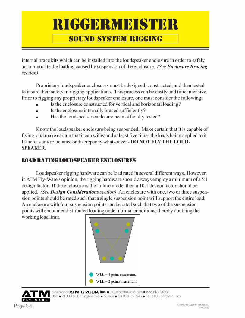
Loudspeaker rigging hardware can be load rated in several different ways. However,in ATM Fly-Ware's opinion, the rigging hardware should always employ a minimum of a 5:1design factor. If the enclosure is the failure mode, then a 10:1 design factor should beapplied. (See Design Considerations section) An enclosure with one, two or three suspen-sion points should be rated such that a single suspension point will support the entire load.An enclosure with four suspension points can be rated such that two of the suspensionpoints will encounter distributed loading under normal conditions, thereby doubling theworking load limit.
SOUND SYSTEM RIGGING
WLL = 1 point maximum.
WLL = 2 points maximum.
RIGGERMEISTER
a division of , Inc. ! www.atmflyware.com ! 888.RIG.MOREUSA ! 21000 S Wilmington Ave ! Carson ! CA 90810-1247 ! Tel 310.834.5914 Fax 310.834.3042
Page E-3Copyright 2002, ATM Group, Inc.199 05252
Another important part of load rating loudspeaker rigging hardware is the certifica-tion process for overhead lifting applications. Many components classified as cargo con-trol hardware, chain, aircraft hardware, and various other hardware components do not carryload ratings for overhead lifting. In fact, many of the aforementioned components arespecifically designated for non-overhead lifting applications only. Below are a sampling ofthe clauses manufacturers of commonly found loudspeaker enclosure component hardwarepublish within their product literature;
! It is the owner's and user's responsibility to determine suitability of aproduct for any particular use.
! No straps are to be used for lifting purposes.! Not recommended for overhead lifting.
This issue can be resolved by individually testing the component and certifying itsuse in overhead lifting applications. Be aware, however, that this process will void anyclaim made against the manufacturer of the component should any type of failure or damagetake place. If this method of certifying the loudspeaker enclosure for overhead lifting isemployed, be certain to document everything well, and to retain copies of the testing resultsindefinitely. The responsibility for the safety of the loudspeaker enclosure is in the handsof the loudspeaker builder, not the hardware manufacturer.
Another issue to be aware of when examining load ratings of loudspeaker enclosuresis the origin of the load rating itself. Load ratings can be found as a result of the ultimatestrength load of the component, or as a result of the yield strength load of the component.(See Design Considerations section) Either of the two load rating measurement methodscan be used by hardware manufacturers, and each of the two methods has its advantages.What is important to the rigging professional is to know which method is being used by thehardware manufacturer, and what limitations may exist due to the measurement method.
LOUDSPEAKER ENCLOSURE CONSTRUCTION
Loudspeaker enclosures are constructed in many different ways; it is not possible tolist all the methods of joinery and material types in the space available for this topic. How-ever, there a few popular conventions used throughout the professional loudspeaker enclo-sure manufacturing industry which represent the majority of professional loudspeakerenclosure constructions. Contact the loudspeaker manufacturer or
SOUND SYSTEM RIGGING
RIGGERMEISTER
a division of , Inc. ! www.atmflyware.com ! 888.RIG.MOREUSA ! 21000 S Wilmington Ave ! Carson ! CA 90810-1247 ! Tel 310.834.5914 Fax
Copyright 2002, ATM Group, Inc.199 05252Page E-4
Various types of fasteners are used to hold the seams of the joints together whileglue sets the joint. Some manufacturers will not use fasteners at all, and hold the jointtight with clamping presses. Either way, there is no considerable gain in strength.
In order to strengthen the joint of the enclosure, a brace of some kind must beemployed. Both internal and external bracing systems are effective, however internalbracing is the most common, and will therefore be examined more closely. The theorybehind both internal and external brace systems is the same.
SOUND SYSTEM RIGGING
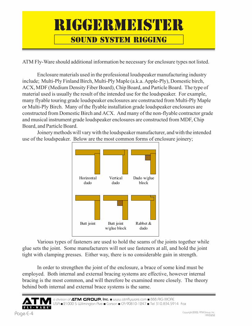
Horizontal dado
Vertical dado
Dado w/glue block
Butt joint Butt joint w/glue block
Rabbet & dado
ATM Fly-Ware should additional information be necessary for enclosure types not listed.
Enclosure materials used in the professional loudspeaker manufacturing industryinclude; Multi-Ply Finland Birch, Multi-Ply Maple (a.k.a. Apple-Ply), Domestic birch,ACX, MDF (Medium Density Fiber Board), Chip Board, and Particle Board. The type ofmaterial used is usually the result of the intended use for the loudspeaker. For example,many flyable touring grade loudspeaker enclosures are constructed from Multi-Ply Mapleor Multi-Ply Birch. Many of the flyable installation grade loudspeaker enclosures areconstructed from Domestic Birch and ACX. And many of the non-flyable contractor gradeand musical instrument grade loudspeaker enclosures are constructed from MDF, ChipBoard, and Particle Board.
Joinery methods will vary with the loudspeaker manufacturer, and with the intendeduse of the loudspeaker. Below are the most common forms of enclosure joinery;
RIGGERMEISTER
a division of , Inc. ! www.atmflyware.com ! 888.RIG.MOREUSA ! 21000 S Wilmington Ave ! Carson ! CA 90810-1247 ! Tel 310.834.5914 Fax 310.834.3042
Page E-5Copyright 2002, ATM Group, Inc.199 05252
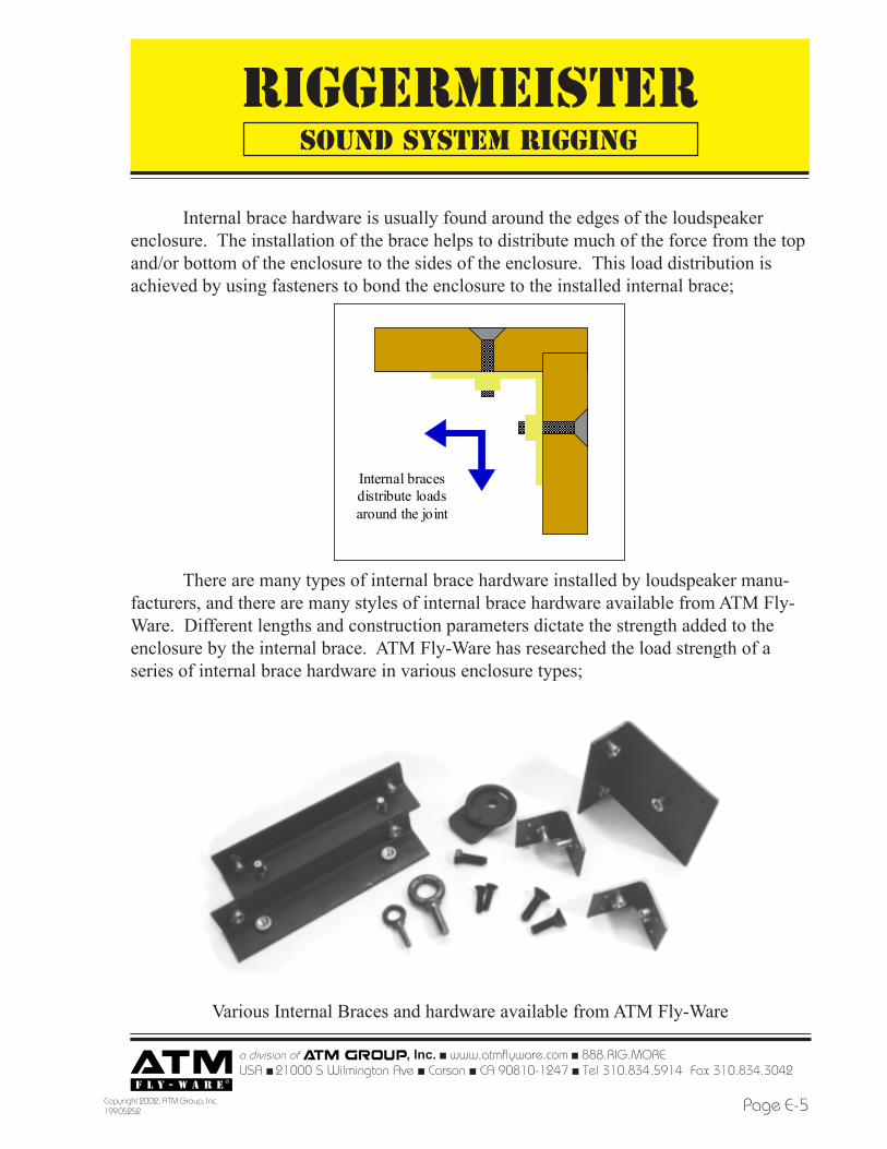
Internal brace hardware is usually found around the edges of the loudspeakerenclosure. The installation of the brace helps to distribute much of the force from the topand/or bottom of the enclosure to the sides of the enclosure. This load distribution isachieved by using fasteners to bond the enclosure to the installed internal brace;
There are many types of internal brace hardware installed by loudspeaker manu-facturers, and there are many styles of internal brace hardware available from ATM Fly-Ware. Different lengths and construction parameters dictate the strength added to theenclosure by the internal brace. ATM Fly-Ware has researched the load strength of aseries of internal brace hardware in various enclosure types;
Various Internal Braces and hardware available from ATM Fly-Ware
SOUND SYSTEM RIGGING
Internal braces distribute loads around the joint
RIGGERMEISTER
a division of , Inc. ! www.atmflyware.com ! 888.RIG.MOREUSA ! 21000 S Wilmington Ave ! Carson ! CA 90810-1247 ! Tel 310.834.5914 Fax
Copyright 2002, ATM Group, Inc.199 05252Page E-6
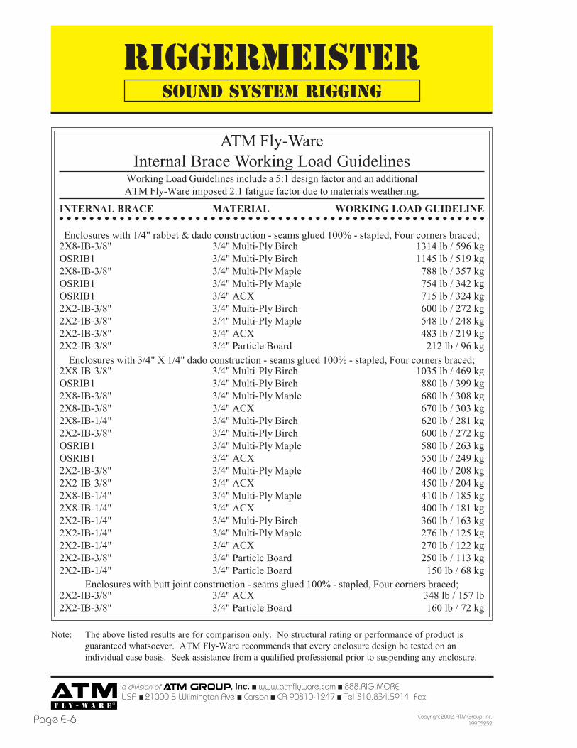
ATM Fly-WareInternal Brace Working Load Guidelines
Working Load Guidelines include a 5:1 design factor and an additionalATM Fly-Ware imposed 2:1 fatigue factor due to materials weathering.
○ ○ ○ ○ ○ ○ ○ ○ ○ ○ ○ ○ ○ ○ ○ ○ ○ ○ ○ ○ ○ ○ ○ ○ ○ ○ ○ ○ ○ ○ ○ ○ ○ ○ ○ ○ ○ ○ ○ ○ ○ ○ ○ ○ ○ ○ ○ ○ ○ ○ ○ ○ ○ ○ ○ ○ ○
INTERNAL BRACE
2X8-IB-3/8"OSRIB12X8-IB-3/8"OSRIB1OSRIB12X2-IB-3/8"2X2-IB-3/8"2X2-IB-3/8"2X2-IB-3/8"
2X8-IB-3/8"OSRIB12X8-IB-3/8"2X8-IB-3/8"2X8-IB-1/4"2X2-IB-3/8"OSRIB1OSRIB12X2-IB-3/8"2X2-IB-3/8"2X8-IB-1/4"2X8-IB-1/4"2X2-IB-1/4"2X2-IB-1/4"2X2-IB-1/4"2X2-IB-3/8"2X2-IB-1/4"
2X2-IB-3/8"2X2-IB-3/8"
MATERIAL
3/4" Multi-Ply Birch3/4" Multi-Ply Birch3/4" Multi-Ply Maple3/4" Multi-Ply Maple3/4" ACX3/4" Multi-Ply Birch3/4" Multi-Ply Maple3/4" ACX3/4" Particle Board
3/4" Multi-Ply Birch3/4" Multi-Ply Birch3/4" Multi-Ply Maple3/4" ACX3/4" Multi-Ply Birch3/4" Multi-Ply Birch3/4" Multi-Ply Maple3/4" ACX3/4" Multi-Ply Maple3/4" ACX3/4" Multi-Ply Maple3/4" ACX3/4" Multi-Ply Birch3/4" Multi-Ply Maple3/4" ACX3/4" Particle Board3/4" Particle Board
3/4" ACX3/4" Particle Board
WORKING LOAD GUIDELINE
1314 lb / 596 kg1145 lb / 519 kg
788 lb / 357 kg754 lb / 342 kg715 lb / 324 kg600 lb / 272 kg548 lb / 248 kg483 lb / 219 kg
212 lb / 96 kg
1035 lb / 469 kg880 lb / 399 kg680 lb / 308 kg670 lb / 303 kg620 lb / 281 kg600 lb / 272 kg580 lb / 263 kg550 lb / 249 kg460 lb / 208 kg450 lb / 204 kg410 lb / 185 kg400 lb / 181 kg360 lb / 163 kg276 lb / 125 kg270 lb / 122 kg250 lb / 113 kg
150 lb / 68 kg
348 lb / 157 lb160 lb / 72 kg
Enclosures with 1/4" rabbet & dado construction - seams glued 100% - stapled, Four corners braced;
Enclosures with 3/4" X 1/4" dado construction - seams glued 100% - stapled, Four corners braced;
Enclosures with butt joint construction - seams glued 100% - stapled, Four corners braced;
Note: The above listed results are for comparison only. No structural rating or performance of product isguaranteed whatsoever. ATM Fly-Ware recommends that every enclosure design be tested on anindividual case basis. Seek assistance from a qualified professional prior to suspending any enclosure.
SOUND SYSTEM RIGGING
RIGGERMEISTER
a division of , Inc. ! www.atmflyware.com ! 888.RIG.MOREUSA ! 21000 S Wilmington Ave ! Carson ! CA 90810-1247 ! Tel 310.834.5914 Fax 310.834.3042
Page E-7Copyright 2002, ATM Group, Inc.199 05252
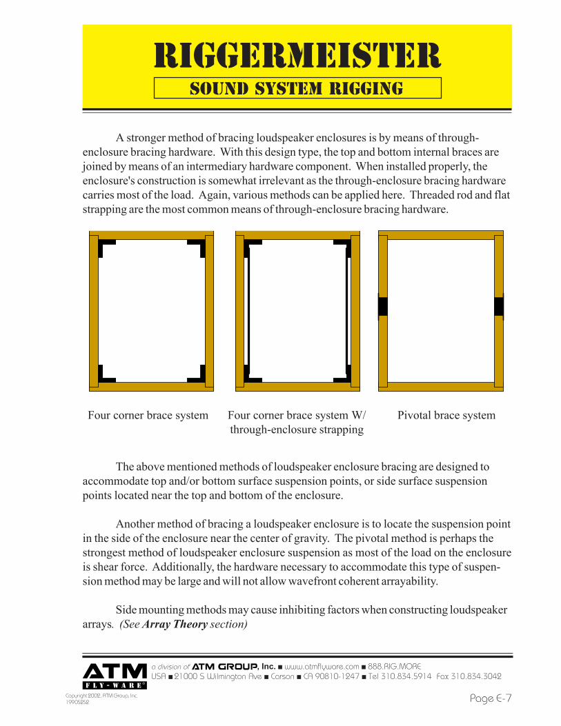
A stronger method of bracing loudspeaker enclosures is by means of through-enclosure bracing hardware. With this design type, the top and bottom internal braces arejoined by means of an intermediary hardware component. When installed properly, theenclosure's construction is somewhat irrelevant as the through-enclosure bracing hardwarecarries most of the load. Again, various methods can be applied here. Threaded rod and flatstrapping are the most common means of through-enclosure bracing hardware.
The above mentioned methods of loudspeaker enclosure bracing are designed toaccommodate top and/or bottom surface suspension points, or side surface suspensionpoints located near the top and bottom of the enclosure.
Another method of bracing a loudspeaker enclosure is to locate the suspension pointin the side of the enclosure near the center of gravity. The pivotal method is perhaps thestrongest method of loudspeaker enclosure suspension as most of the load on the enclosureis shear force. Additionally, the hardware necessary to accommodate this type of suspen-sion method may be large and will not allow wavefront coherent arrayability.
Side mounting methods may cause inhibiting factors when constructing loudspeakerarrays. (See Array Theory section)
SOUND SYSTEM RIGGING
Four corner brace system Four corner brace system W/through-enclosure strapping
Pivotal brace system
RIGGERMEISTER
a division of , Inc. ! www.atmflyware.com ! 888.RIG.MOREUSA ! 21000 S Wilmington Ave ! Carson ! CA 90810-1247 ! Tel 310.834.5914 Fax
Copyright 2002, ATM Group, Inc.199 05252Page E-8
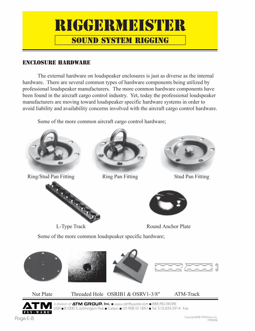
ENCLOSURE HARDWARE
The external hardware on loudspeaker enclosures is just as diverse as the internalhardware. There are several common types of hardware components being utilized byprofessional loudspeaker manufacturers. The more common hardware components havebeen found in the aircraft cargo control industry. Yet, today the professional loudspeakermanufacturers are moving toward loudspeaker specific hardware systems in order toavoid liability and availability concerns involved with the aircraft cargo control hardware.
Some of the more common aircraft cargo control hardware;
Ring Pan FittingRing/Stud Pan Fitting Stud Pan Fitting
L-Type Track Round Anchor Plate
Nut Plate
Some of the more common loudspeaker specific hardware;
SOUND SYSTEM RIGGING
ATM-TrackThreaded Hole OSRIB1 & OSRV1-3/8"
RIGGERMEISTER
a division of , Inc. ! www.atmflyware.com ! 888.RIG.MOREUSA ! 21000 S Wilmington Ave ! Carson ! CA 90810-1247 ! Tel 310.834.5914 Fax 310.834.3042
Page E-9Copyright 2002, ATM Group, Inc.199 05252
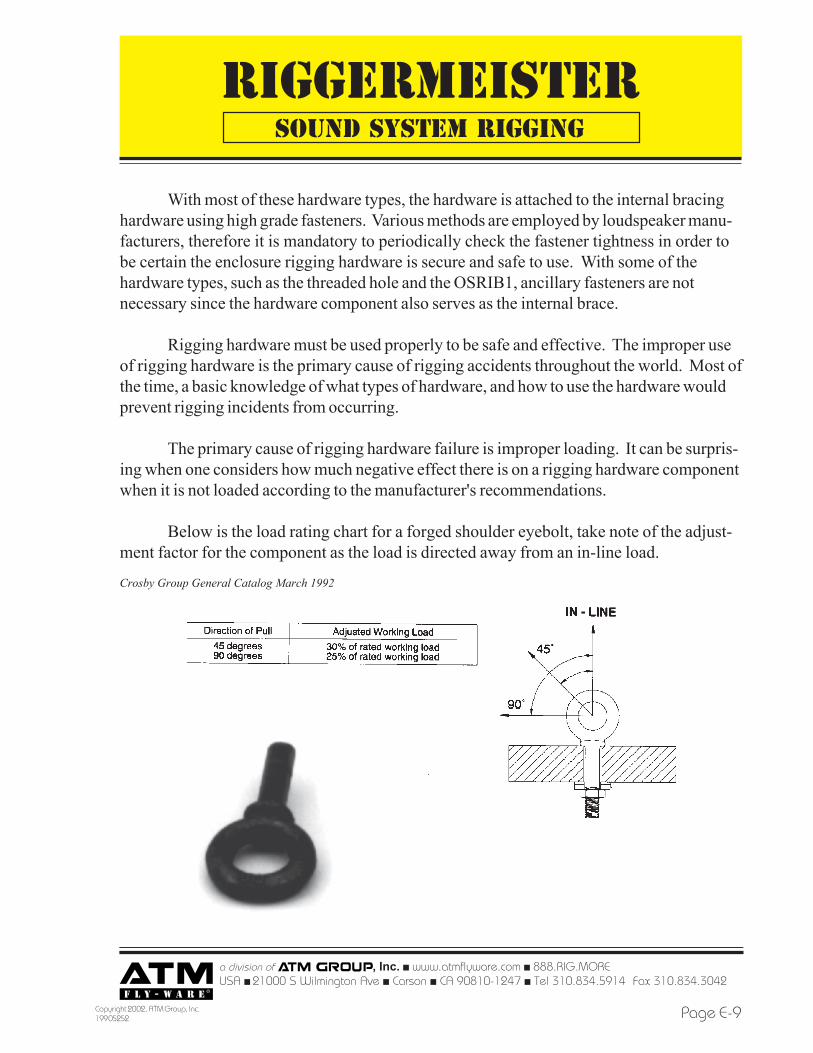
With most of these hardware types, the hardware is attached to the internal bracinghardware using high grade fasteners. Various methods are employed by loudspeaker manu-facturers, therefore it is mandatory to periodically check the fastener tightness in order tobe certain the enclosure rigging hardware is secure and safe to use. With some of thehardware types, such as the threaded hole and the OSRIB1, ancillary fasteners are notnecessary since the hardware component also serves as the internal brace.
Rigging hardware must be used properly to be safe and effective. The improper useof rigging hardware is the primary cause of rigging accidents throughout the world. Most ofthe time, a basic knowledge of what types of hardware, and how to use the hardware wouldprevent rigging incidents from occurring.
The primary cause of rigging hardware failure is improper loading. It can be surpris-ing when one considers how much negative effect there is on a rigging hardware componentwhen it is not loaded according to the manufacturer's recommendations.
Below is the load rating chart for a forged shoulder eyebolt, take note of the adjust-ment factor for the component as the load is directed away from an in-line load.
SOUND SYSTEM RIGGING
Crosby Group General Catalog March 1992
RIGGERMEISTER
a division of , Inc. ! www.atmflyware.com ! 888.RIG.MOREUSA ! 21000 S Wilmington Ave ! Carson ! CA 90810-1247 ! Tel 310.834.5914 Fax
Copyright 2002, ATM Group, Inc.199 05252Page E-10
SOUND SYSTEM RIGGING
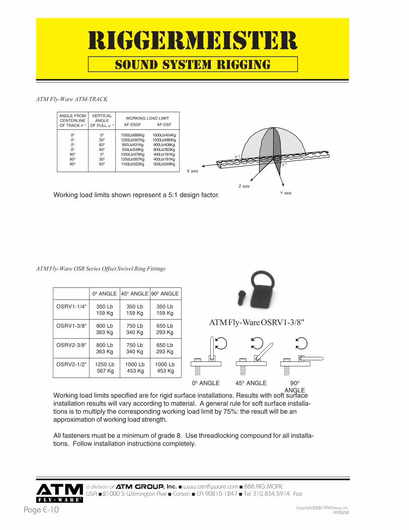
Working load limits shown represent a 5:1 design factor. Y axis
Z axis
X axis
AF-DSSF
1500Lb/680Kg1250Lb/567Kg950Lb/431Kg550Lb/249Kg1050Lb/476Kg1250Lb/567Kg1150Lb/522Kg
AF-DSF
1000Lb/454Kg1500Lb/680Kg900Lb/408Kg800Lb/363Kg400Lb/181Kg400Lb/181Kg550Lb/249Kg
VERTICALANGLE
OF PULL ψ 0
00
300
600
900
00
300
600
ANGLE FROMCENTERLINEOF TRACK θ 0
00
00
00
00
900
900
900
WORKING LOAD LIMIT
θ 0
ATM Fly-Ware ATM-TRACK
ψ 0
00 ANGLE 900
ANGLE450 ANGLE
OSRV1-1/4"
OSRV1-3/8"
OSRV2-3/8"
OSRV2-1/2"
00 ANGLE
350 Lb159 Kg
800 Lb363 Kg
800 Lb363 Kg
1250 Lb 567 Kg
450 ANGLE
350 Lb159 Kg
750 Lb340 Kg
750 Lb340 Kg
1000 Lb 453 Kg
900 ANGLE
350 Lb159 Kg
650 Lb293 Kg
650 Lb293 Kg
1000 Lb 453 Kg
Working load limits specified are for rigid surface installations. Results with soft surfaceinstallation results will vary according to material. A general rule for soft surface installa-tions is to multiply the corresponding working load limit by 75%: the result will be anapproximation of working load strength.
All fasteners must be a minimum of grade 8. Use threadlocking compound for all installa-tions. Follow installation instructions completely.
ATM Fly-Ware OSR Series Offset Swivel Ring Fittings
ATM Fly-Ware OSRV1-3/8"
RIGGERMEISTER
a division of , Inc. ! www.atmflyware.com ! 888.RIG.MOREUSA ! 21000 S Wilmington Ave ! Carson ! CA 90810-1247 ! Tel 310.834.5914 Fax 310.834.3042
Page E-11Copyright 2002, ATM Group, Inc.199 05252
SOUND SYSTEM RIGGING
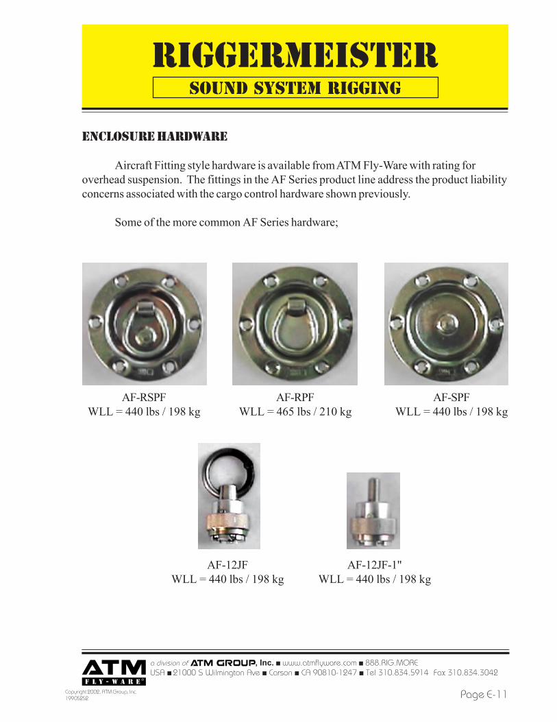
ENCLOSURE HARDWARE
Aircraft Fitting style hardware is available from ATM Fly-Ware with rating foroverhead suspension. The fittings in the AF Series product line address the product liabilityconcerns associated with the cargo control hardware shown previously.
Some of the more common AF Series hardware;
AF-RPFWLL = 465 lbs / 210 kg
AF-RSPFWLL = 440 lbs / 198 kg
AF-SPFWLL = 440 lbs / 198 kg
AF-12JF-1"WLL = 440 lbs / 198 kg
AF-12JFWLL = 440 lbs / 198 kg
RIGGERMEISTER
a division of , Inc. ! www.atmflyware.com ! 888.RIG.MOREUSA ! 21000 S Wilmington Ave ! Carson ! CA 90810-1247 ! Tel 310.834.5914 Fax
Copyright 2002, ATM Group, Inc.199 05252Page E-12
SOUND SYSTEM RIGGING
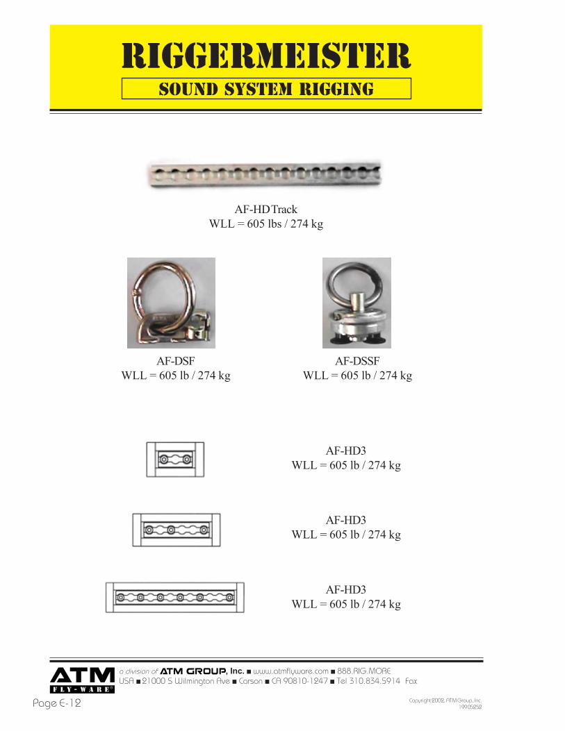
AF-HD TrackWLL = 605 lbs / 274 kg
AF-DSSFWLL = 605 lb / 274 kg
AF-DSFWLL = 605 lb / 274 kg
AF-HD3WLL = 605 lb / 274 kg
AF-HD3WLL = 605 lb / 274 kg
AF-HD3WLL = 605 lb / 274 kg
RIGGERMEISTER
a division of , Inc. ! www.atmflyware.com ! 888.RIG.MOREUSA ! 21000 S Wilmington Ave ! Carson ! CA 90810-1247 ! Tel 310.834.5914 Fax 310.834.3042
Page E-13Copyright 2002, ATM Group, Inc.199 05252
ARRAY THEORY
Some feel loudspeaker array theory is a somewhat controversial subject. As withany controversial subject, the arguments lie in the measures and balances of the dataavailable. ATM Fly-Ware has invested a great deal of resources toward "loudspeakerarray technology" in order to provide quality rigging products to the sound reinforcementindustries.
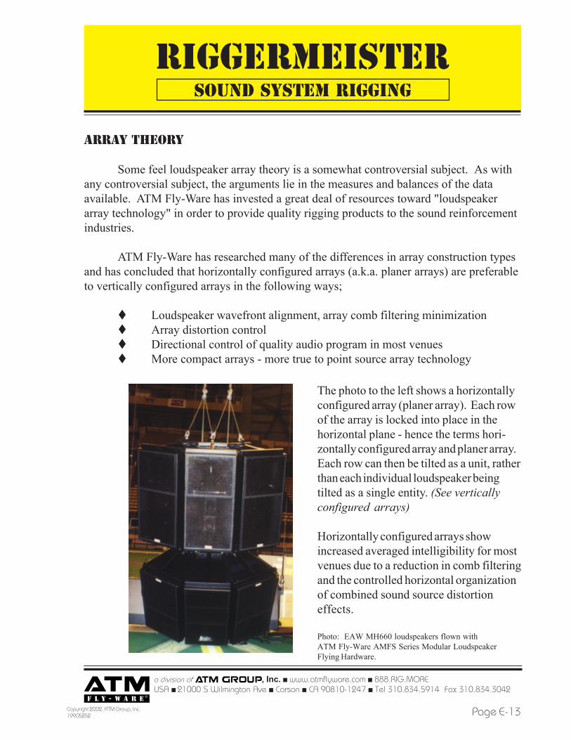
ATM Fly-Ware has researched many of the differences in array construction typesand has concluded that horizontally configured arrays (a.k.a. planer arrays) are preferableto vertically configured arrays in the following ways;
! Loudspeaker wavefront alignment, array comb filtering minimization! Array distortion control! Directional control of quality audio program in most venues! More compact arrays - more true to point source array technology
The photo to the left shows a horizontallyconfigured array (planer array). Each rowof the array is locked into place in thehorizontal plane - hence the terms hori-zontally configured array and planer array.Each row can then be tilted as a unit, ratherthan each individual loudspeaker beingtilted as a single entity. (See verticallyconfigured arrays)
Horizontally configured arrays showincreased averaged intelligibility for mostvenues due to a reduction in comb filteringand the controlled horizontal organizationof combined sound source distortioneffects.
Photo: EAW MH660 loudspeakers flown withATM Fly-Ware AMFS Series Modular LoudspeakerFlying Hardware.
SOUND SYSTEM RIGGING
RIGGERMEISTER
a division of , Inc. ! www.atmflyware.com ! 888.RIG.MOREUSA ! 21000 S Wilmington Ave ! Carson ! CA 90810-1247 ! Tel 310.834.5914 Fax
Copyright 2002, ATM Group, Inc.199 05252Page E-14
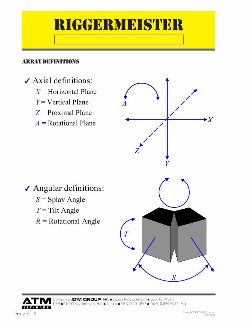
ARRAY DEFINITIONS
✔ Axial definitions:X = Horizontal PlaneY = Vertical PlaneZ = Proximal PlaneA = Rotational Plane X
Y
Z
A
X
Y
Z
A
✔ Angular definitions:S = Splay AngleT = Tilt AngleR = Rotational Angle
S
T
RIGGERMEISTER
a division of , Inc. ! www.atmflyware.com ! 888.RIG.MOREUSA ! 21000 S Wilmington Ave ! Carson ! CA 90810-1247 ! Tel 310.834.5914 Fax 310.834.3042
Page E-15Copyright 2002, ATM Group, Inc.199 05252
Horizontally configured loudspeaker arrays will inherently maintain acousticwavefront coherency along the horizontal plane since the loudspeaker enclosures arefixed along the z-axis.
As long as the loudspeaker enclosures maintainproper acoustic wavefront alignment, the array willminimize comb filtering and distortion effects causedby misaligned acoustic wavefronts.
ATM Fly-Ware AMFS Series LoudspeakerFlying Hardware also enables the loudspeaker array tobe configured so that the vertical acoustic wavefrontsbetween rows can be aligned as well.
Horizontally configured arrays are not without distortion: the interaction betweenrows of loudspeakers will cause comb filtering. However, in most venues, distortion andfiltering effects in the horizontal plane will not be as damaging to average sound systemintelligibility since the seating areas effected will number fewer in the horizontal planethan in the vertical plane. Horizontally configured arrays can be configured so that inmany venues the unwanted horizontal coverage can be directed toward areas withoutseating, such as a balcony face or aisle way.
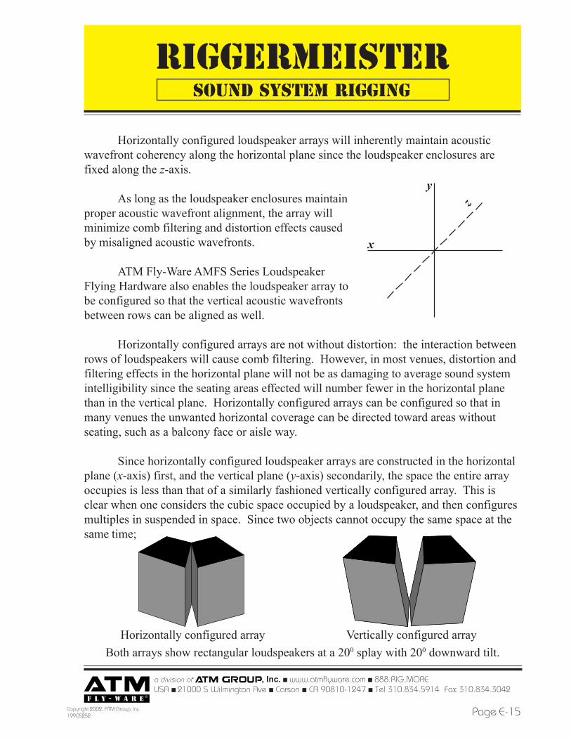
Since horizontally configured loudspeaker arrays are constructed in the horizontalplane (x-axis) first, and the vertical plane (y-axis) secondarily, the space the entire arrayoccupies is less than that of a similarly fashioned vertically configured array. This isclear when one considers the cubic space occupied by a loudspeaker, and then configuresmultiples in suspended in space. Since two objects cannot occupy the same space at thesame time;
y
x
Horizontally configured array Vertically configured arrayBoth arrays show rectangular loudspeakers at a 200 splay with 200 downward tilt.
z
SOUND SYSTEM RIGGING
RIGGERMEISTER
a division of , Inc. ! www.atmflyware.com ! 888.RIG.MOREUSA ! 21000 S Wilmington Ave ! Carson ! CA 90810-1247 ! Tel 310.834.5914 Fax
Copyright 2002, ATM Group, Inc.199 05252Page E-16
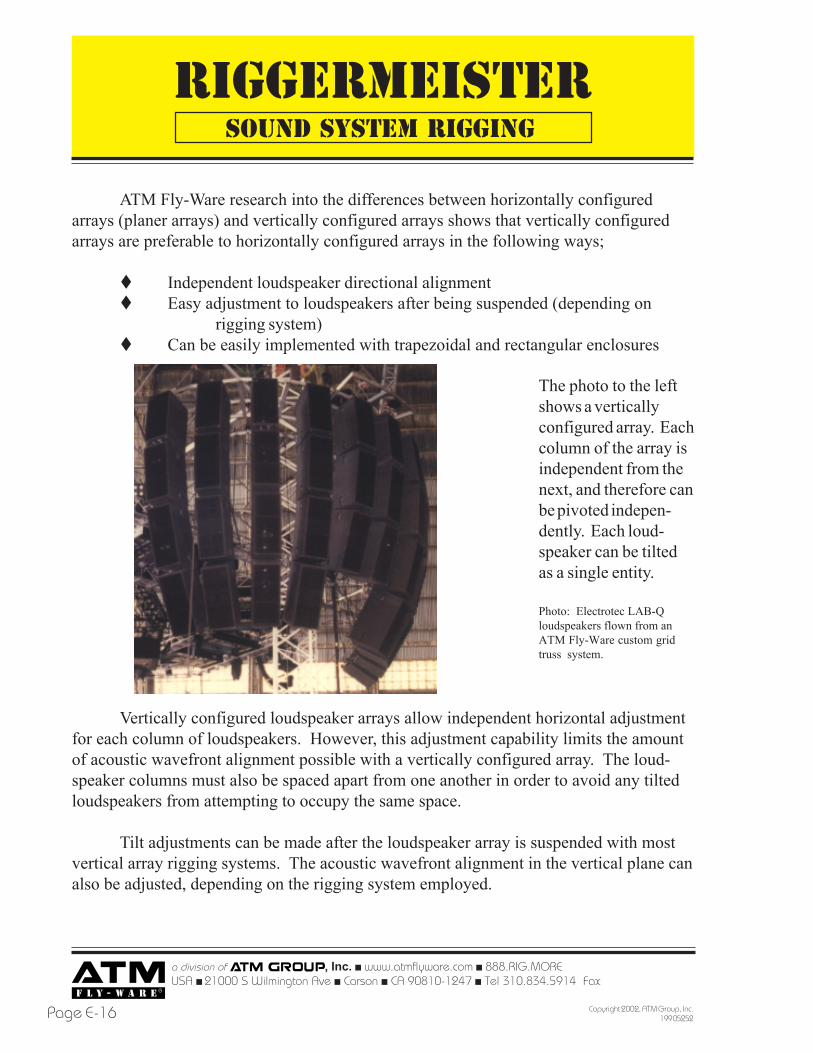
ATM Fly-Ware research into the differences between horizontally configuredarrays (planer arrays) and vertically configured arrays shows that vertically configuredarrays are preferable to horizontally configured arrays in the following ways;
! Independent loudspeaker directional alignment! Easy adjustment to loudspeakers after being suspended (depending on
rigging system)! Can be easily implemented with trapezoidal and rectangular enclosures
The photo to the leftshows a verticallyconfigured array. Eachcolumn of the array isindependent from thenext, and therefore canbe pivoted indepen-dently. Each loud-speaker can be tiltedas a single entity.
Photo: Electrotec LAB-Qloudspeakers flown from anATM Fly-Ware custom gridtruss system.
Vertically configured loudspeaker arrays allow independent horizontal adjustmentfor each column of loudspeakers. However, this adjustment capability limits the amountof acoustic wavefront alignment possible with a vertically configured array. The loud-speaker columns must also be spaced apart from one another in order to avoid any tiltedloudspeakers from attempting to occupy the same space.
Tilt adjustments can be made after the loudspeaker array is suspended with mostvertical array rigging systems. The acoustic wavefront alignment in the vertical plane canalso be adjusted, depending on the rigging system employed.
SOUND SYSTEM RIGGING
RIGGERMEISTER
a division of , Inc. ! www.atmflyware.com ! 888.RIG.MOREUSA ! 21000 S Wilmington Ave ! Carson ! CA 90810-1247 ! Tel 310.834.5914 Fax 310.834.3042
Page E-17Copyright 2002, ATM Group, Inc.199 05252
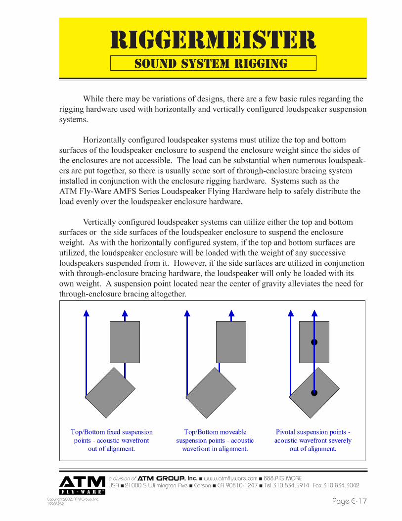
While there may be variations of designs, there are a few basic rules regarding therigging hardware used with horizontally and vertically configured loudspeaker suspensionsystems.
Horizontally configured loudspeaker systems must utilize the top and bottomsurfaces of the loudspeaker enclosure to suspend the enclosure weight since the sides ofthe enclosures are not accessible. The load can be substantial when numerous loudspeak-ers are put together, so there is usually some sort of through-enclosure bracing systeminstalled in conjunction with the enclosure rigging hardware. Systems such as theATM Fly-Ware AMFS Series Loudspeaker Flying Hardware help to safely distribute theload evenly over the loudspeaker enclosure hardware.
Vertically configured loudspeaker systems can utilize either the top and bottomsurfaces or the side surfaces of the loudspeaker enclosure to suspend the enclosureweight. As with the horizontally configured system, if the top and bottom surfaces areutilized, the loudspeaker enclosure will be loaded with the weight of any successiveloudspeakers suspended from it. However, if the side surfaces are utilized in conjunctionwith through-enclosure bracing hardware, the loudspeaker will only be loaded with itsown weight. A suspension point located near the center of gravity alleviates the need forthrough-enclosure bracing altogether.
SOUND SYSTEM RIGGING
Top/Bottom fixed suspension points - acoustic wavefront
out of alignment.
Top/Bottom moveable suspension points - acoustic
wavefront in alignment.
Pivotal suspension points -acoustic wavefront severely
out of alignment.
RIGGERMEISTER
a division of , Inc. ! www.atmflyware.com ! 888.RIG.MOREUSA ! 21000 S Wilmington Ave ! Carson ! CA 90810-1247 ! Tel 310.834.5914 Fax
Copyright 2002, ATM Group, Inc.199 05252Page E-18
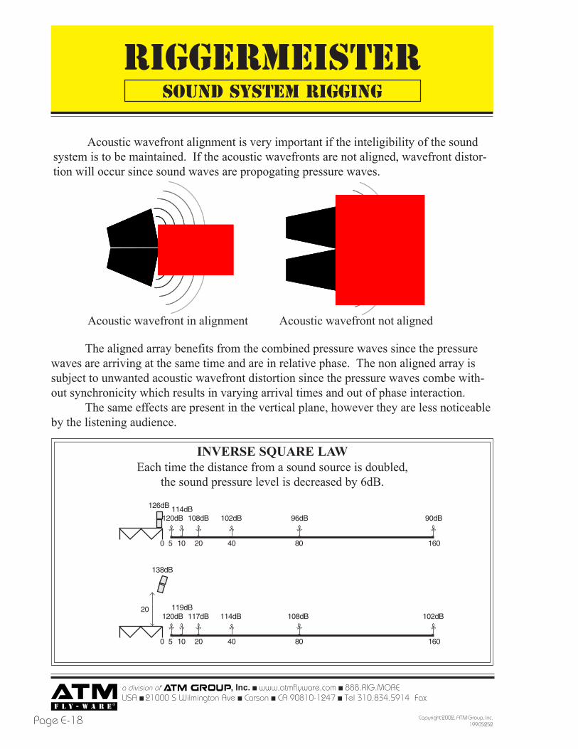
Acoustic wavefront alignment is very important if the inteligibility of the soundsystem is to be maintained. If the acoustic wavefronts are not aligned, wavefront distor-tion will occur since sound waves are propogating pressure waves.
SOUND SYSTEM RIGGING
Acoustic wavefront in alignment Acoustic wavefront not aligned
The aligned array benefits from the combined pressure waves since the pressurewaves are arriving at the same time and are in relative phase. The non aligned array issubject to unwanted acoustic wavefront distortion since the pressure waves combe with-out synchronicity which results in varying arrival times and out of phase interaction.
The same effects are present in the vertical plane, however they are less noticeableby the listening audience.
INVERSE SQUARE LAWEach time the distance from a sound source is doubled,
the sound pressure level is decreased by 6dB.
16040 80205 100
120dB 108dB114dB126dB
96dB 90dB
16040 80205 100
120dB 117dB119dB
138dB
114dB 108dB 102dB20
102dB
RIGGERMEISTER
a division of , Inc. ! www.atmflyware.com ! 888.RIG.MOREUSA ! 21000 S Wilmington Ave ! Carson ! CA 90810-1247 ! Tel 310.834.5914 Fax 310.834.3042
Page E-19Copyright 2002, ATM Group, Inc.199 05252
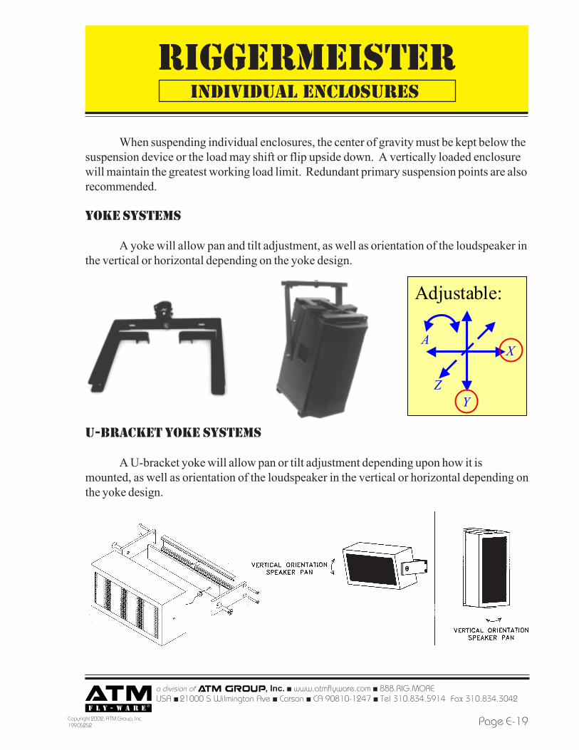
When suspending individual enclosures, the center of gravity must be kept below thesuspension device or the load may shift or flip upside down. A vertically loaded enclosurewill maintain the greatest working load limit. Redundant primary suspension points are alsorecommended.
yoke systems
A yoke will allow pan and tilt adjustment, as well as orientation of the loudspeaker inthe vertical or horizontal depending on the yoke design.
individual enclosures
Adjustable:
X
YZ
A
u-bracket yoke systems
A U-bracket yoke will allow pan or tilt adjustment depending upon how it ismounted, as well as orientation of the loudspeaker in the vertical or horizontal depending onthe yoke design.
RIGGERMEISTER
a division of , Inc. ! www.atmflyware.com ! 888.RIG.MOREUSA ! 21000 S Wilmington Ave ! Carson ! CA 90810-1247 ! Tel 310.834.5914 Fax
Copyright 2002, ATM Group, Inc.199 05252Page E-20
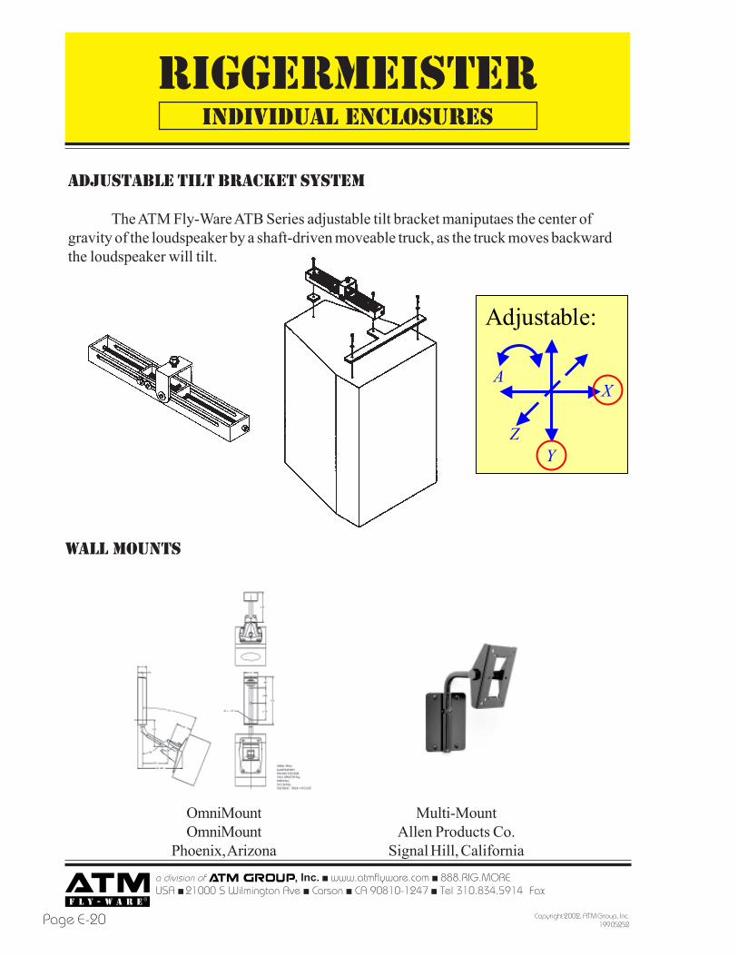
ADJUSTABLE TILT BRACKET system
The ATM Fly-Ware ATB Series adjustable tilt bracket maniputaes the center ofgravity of the loudspeaker by a shaft-driven moveable truck, as the truck moves backwardthe loudspeaker will tilt.
individual enclosures
Adjustable:
X
YZ
A
wall mounts
OmniMountOmniMount
Phoenix, Arizona
Multi-MountAllen Products Co.
Signal Hill, California
RIGGERMEISTER
a division of , Inc. ! www.atmflyware.com ! 888.RIG.MOREUSA ! 21000 S Wilmington Ave ! Carson ! CA 90810-1247 ! Tel 310.834.5914 Fax 310.834.3042
Page E-21Copyright 2002, ATM Group, Inc.199 05252
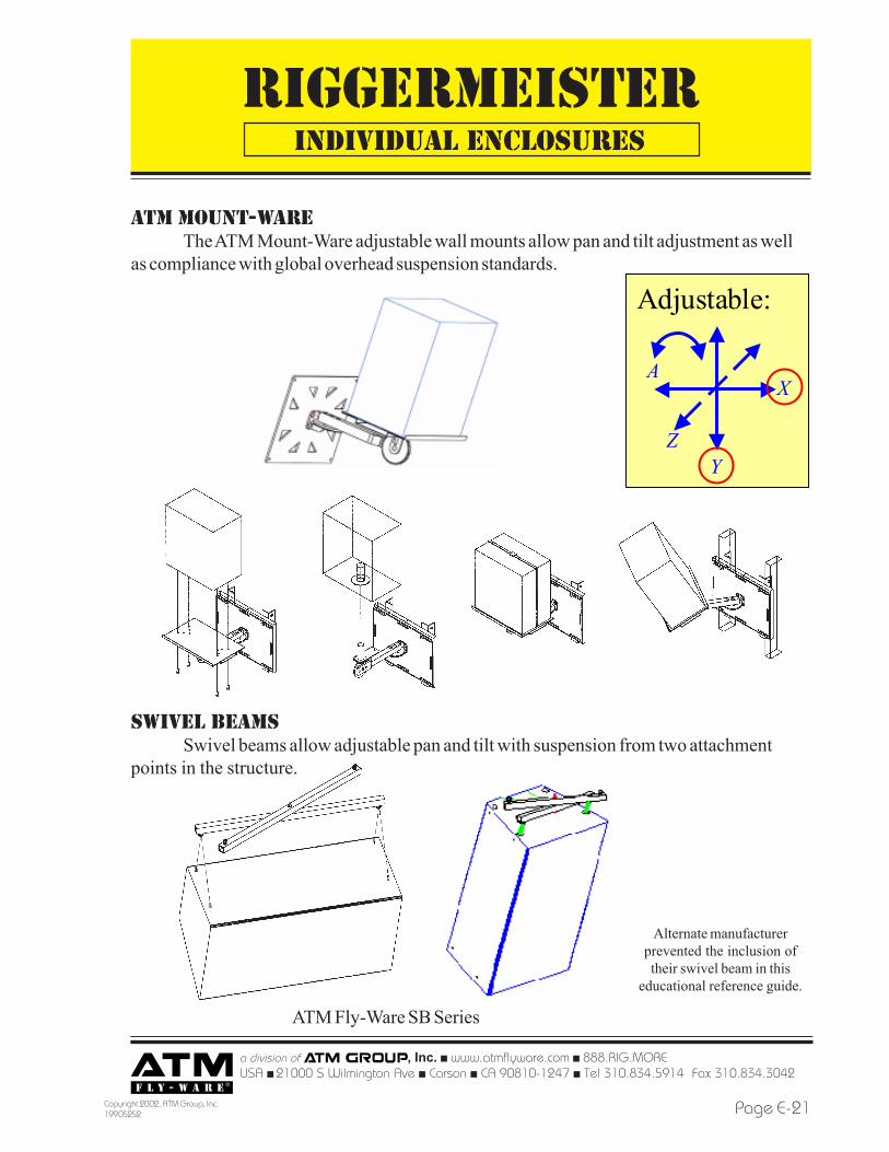
atm mount-wareThe ATM Mount-Ware adjustable wall mounts allow pan and tilt adjustment as well
as compliance with global overhead suspension standards.
individual enclosures
Adjustable:
X
YZ
A
swivel beamsSwivel beams allow adjustable pan and tilt with suspension from two attachment
points in the structure.
ATM Fly-Ware SB Series
Alternate manufacturerprevented the inclusion oftheir swivel beam in this
educational reference guide.
RIGGERMEISTER
a division of , Inc. ! www.atmflyware.com ! 888.RIG.MOREUSA ! 21000 S Wilmington Ave ! Carson ! CA 90810-1247 ! Tel 310.834.5914 Fax
Copyright 2002, ATM Group, Inc.199 05252Page E-22
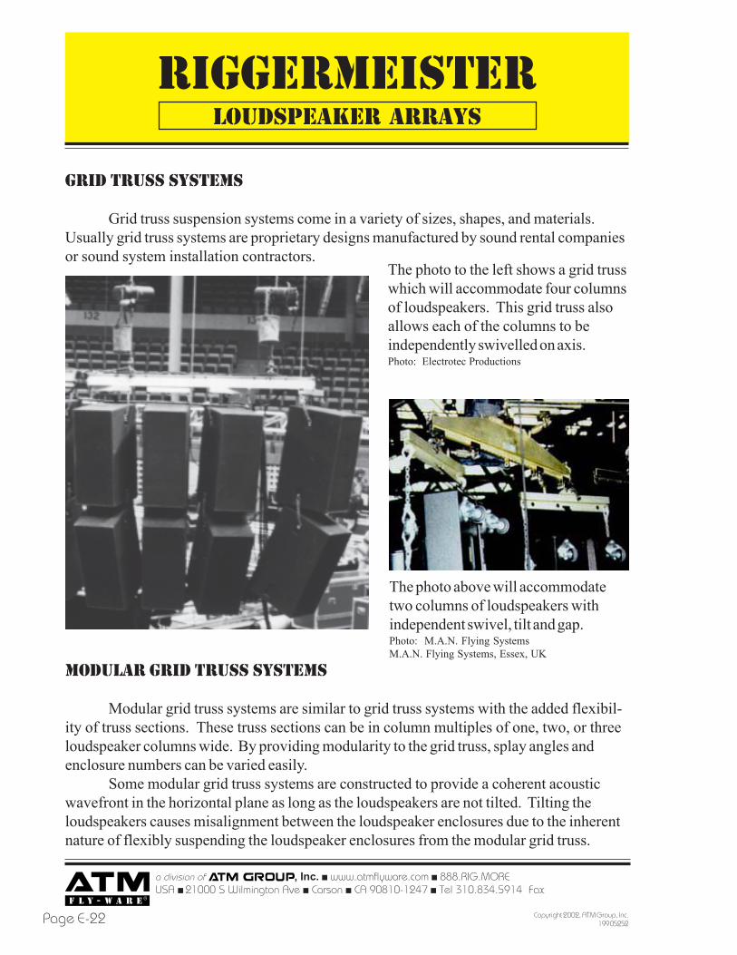
GRID TRUSS SYSTEMS
Grid truss suspension systems come in a variety of sizes, shapes, and materials.Usually grid truss systems are proprietary designs manufactured by sound rental companiesor sound system installation contractors.
The photo to the left shows a grid trusswhich will accommodate four columnsof loudspeakers. This grid truss alsoallows each of the columns to beindependently swivelled on axis.Photo: Electrotec Productions
MODULAR GRID TRUSS SYSTEMS
Modular grid truss systems are similar to grid truss systems with the added flexibil-ity of truss sections. These truss sections can be in column multiples of one, two, or threeloudspeaker columns wide. By providing modularity to the grid truss, splay angles andenclosure numbers can be varied easily.
Some modular grid truss systems are constructed to provide a coherent acousticwavefront in the horizontal plane as long as the loudspeakers are not tilted. Tilting theloudspeakers causes misalignment between the loudspeaker enclosures due to the inherentnature of flexibly suspending the loudspeaker enclosures from the modular grid truss.
LOUDSPEAKER ARRAYS
The photo above will accommodatetwo columns of loudspeakers withindependent swivel, tilt and gap.Photo: M.A.N. Flying SystemsM.A.N. Flying Systems, Essex, UK
RIGGERMEISTER
a division of , Inc. ! www.atmflyware.com ! 888.RIG.MOREUSA ! 21000 S Wilmington Ave ! Carson ! CA 90810-1247 ! Tel 310.834.5914 Fax 310.834.3042
Page E-23Copyright 2002, ATM Group, Inc.199 05252
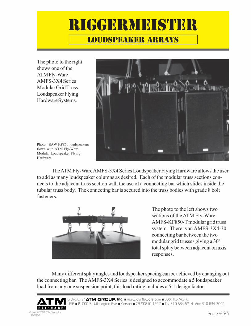
The photo to the rightshows one of theATM Fly-WareAMFS-3X4 SeriesModular Grid TrussLoudspeaker FlyingHardware Systems.
Photo: EAW KF850 loudspeakersflown with ATM Fly-WareModular Loudspeaker FlyingHardware.
The ATM Fly-Ware AMFS-3X4 Series Loudspeaker Flying Hardware allows the userto add as many loudspeaker columns as desired. Each of the modular truss sections con-nects to the adjacent truss section with the use of a connecting bar which slides inside thetubular truss body. The connecting bar is secured into the truss bodies with grade 8 boltfasteners.
Many different splay angles and loudspeaker spacing can be achieved by changing outthe connecting bar. The AMFS-3X4 Series is designed to accommodate a 5 loudspeakerload from any one suspension point, this load rating includes a 5:1 design factor.
The photo to the left shows twosections of the ATM Fly-WareAMFS-KF850-T modular grid trusssystem. There is an AMFS-3X4-30connecting bar between the twomodular grid trusses giving a 300
total splay between adjacent on axisresponses.
LOUDSPEAKER ARRAYS
RIGGERMEISTER
a division of , Inc. ! www.atmflyware.com ! 888.RIG.MOREUSA ! 21000 S Wilmington Ave ! Carson ! CA 90810-1247 ! Tel 310.834.5914 Fax
Copyright 2002, ATM Group, Inc.199 05252Page E-24
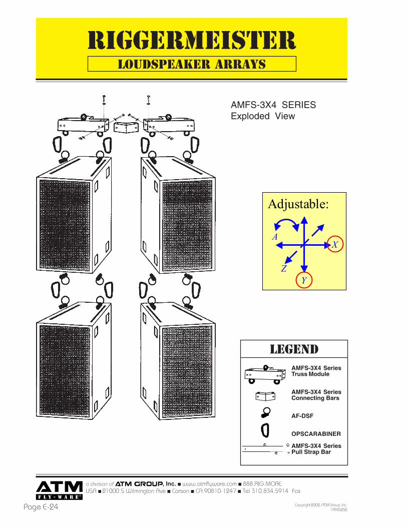
AMFS-3X4 SeriesTruss Module
AMFS-3X4 SeriesConnecting Bars
AF-DSF
OPSCARABINER
AMFS-3X4 SeriesPull Strap Bar
LEGEND
AMFS-3X4 SERIESExploded View
LOUDSPEAKER ARRAYS
Adjustable:
X
YZ
A
RIGGERMEISTER
a division of , Inc. ! www.atmflyware.com ! 888.RIG.MOREUSA ! 21000 S Wilmington Ave ! Carson ! CA 90810-1247 ! Tel 310.834.5914 Fax 310.834.3042
Page E-25Copyright 2002, ATM Group, Inc.199 05252
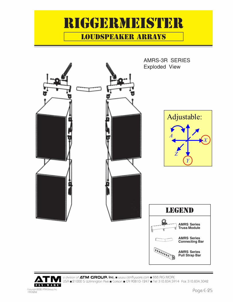
LOUDSPEAKER ARRAYS
AMRS-3R SERIESExploded View
LEGEND
AMRS SeriesTruss Module
AMRS SeriesConnecting Bar
AMRS SeriesPull Strap Bar
Adjustable:
X
YZ
A
RIGGERMEISTER
a division of , Inc. ! www.atmflyware.com ! 888.RIG.MOREUSA ! 21000 S Wilmington Ave ! Carson ! CA 90810-1247 ! Tel 310.834.5914 Fax
Copyright 2002, ATM Group, Inc.199 05252Page E-26
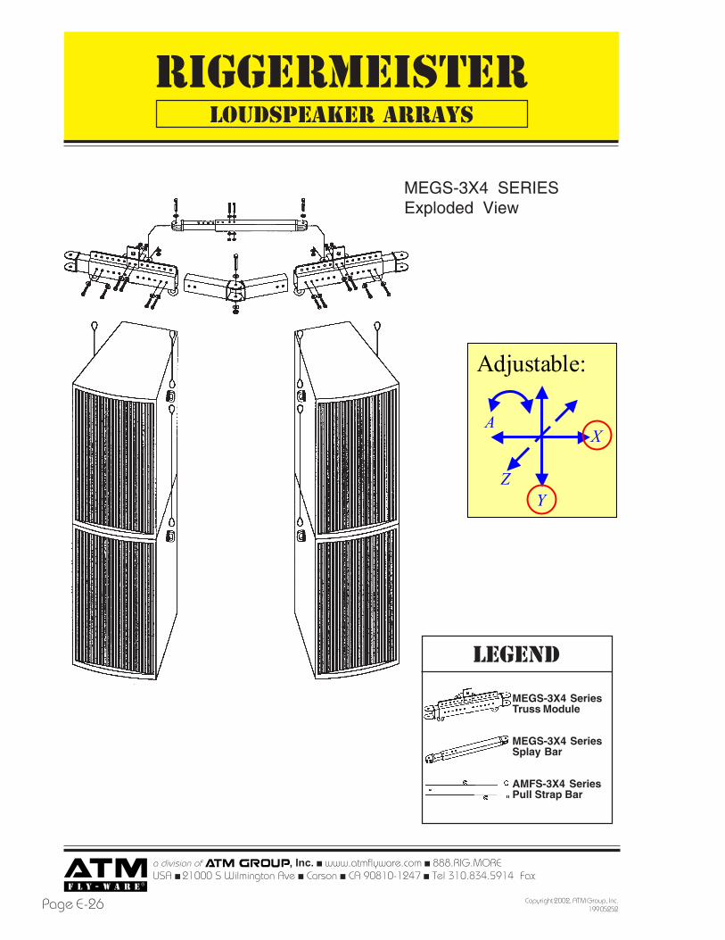
LOUDSPEAKER ARRAYS
MEGS-3X4 SERIESExploded View
LEGEND
MEGS-3X4 SeriesTruss Module
MEGS-3X4 SeriesSplay Bar
AMFS-3X4 SeriesPull Strap Bar
Adjustable:
X
YZ
A
RIGGERMEISTER
a division of , Inc. ! www.atmflyware.com ! 888.RIG.MOREUSA ! 21000 S Wilmington Ave ! Carson ! CA 90810-1247 ! Tel 310.834.5914 Fax 310.834.3042
Page E-27Copyright 2002, ATM Group, Inc.199 05252
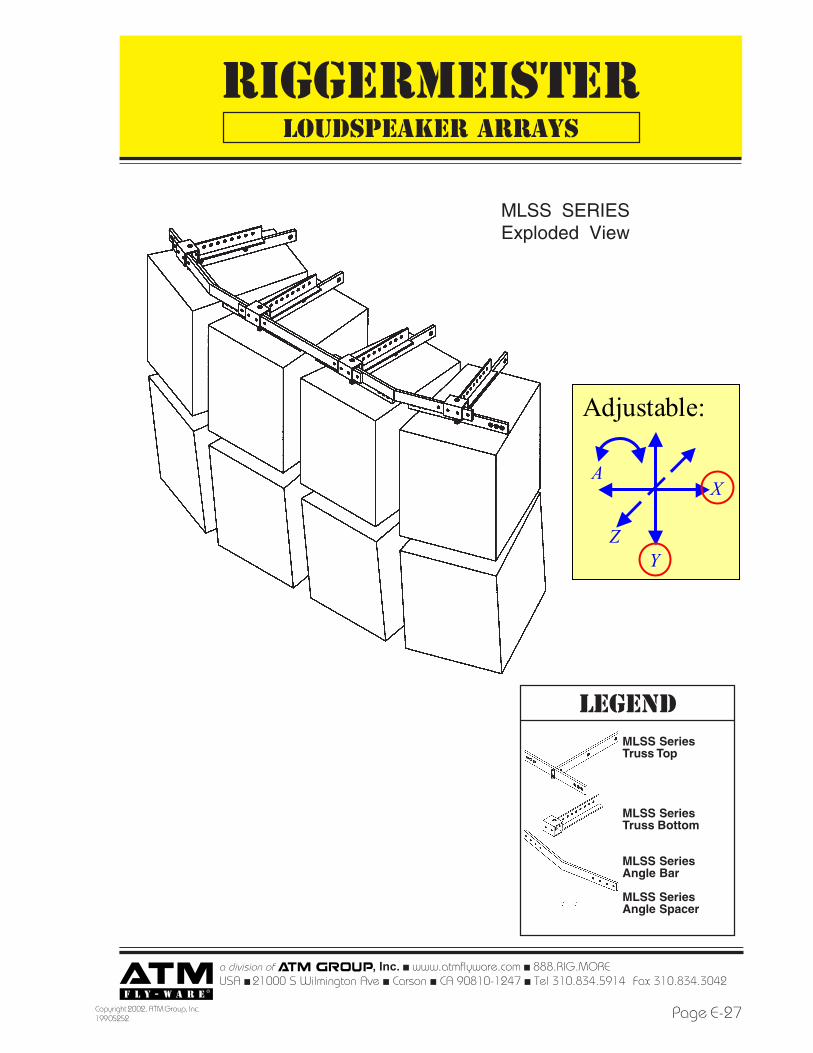
LOUDSPEAKER ARRAYS
MLSS SERIESExploded View
Adjustable:
X
YZ
A
MLSS SeriesTruss Top
MLSS SeriesTruss Bottom
MLSS SeriesAngle Bar
MLSS SeriesAngle Spacer
LEGEND
RIGGERMEISTER
a division of , Inc. ! www.atmflyware.com ! 888.RIG.MOREUSA ! 21000 S Wilmington Ave ! Carson ! CA 90810-1247 ! Tel 310.834.5914 Fax
Copyright 2002, ATM Group, Inc.199 05252Page E-28
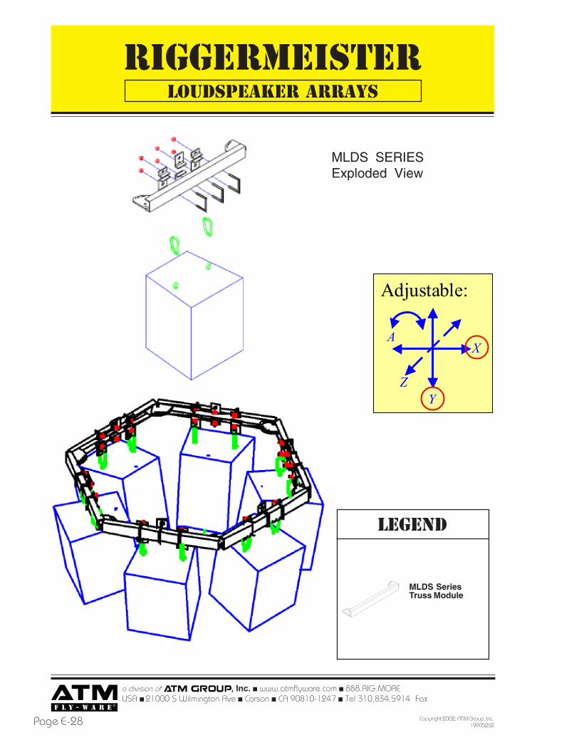
LEGEND
MLDS SeriesTruss Module
LOUDSPEAKER ARRAYS
MLDS SERIESExploded View
Adjustable:
X
YZ
A
RIGGERMEISTER
a division of , Inc. ! www.atmflyware.com ! 888.RIG.MOREUSA ! 21000 S Wilmington Ave ! Carson ! CA 90810-1247 ! Tel 310.834.5914 Fax 310.834.3042
Page E-29Copyright 2002, ATM Group, Inc.199 05252
MODULAR RIGGING HARDWARE SYSTEMS
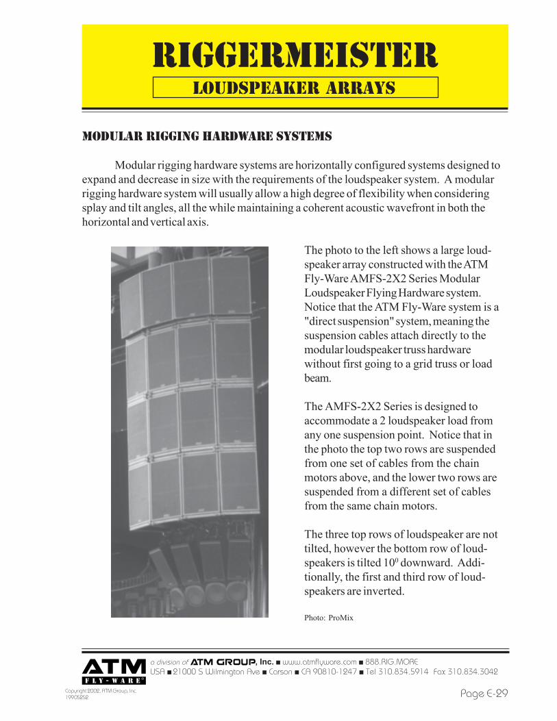
Modular rigging hardware systems are horizontally configured systems designed toexpand and decrease in size with the requirements of the loudspeaker system. A modularrigging hardware system will usually allow a high degree of flexibility when consideringsplay and tilt angles, all the while maintaining a coherent acoustic wavefront in both thehorizontal and vertical axis.
The photo to the left shows a large loud-speaker array constructed with the ATMFly-Ware AMFS-2X2 Series ModularLoudspeaker Flying Hardware system.Notice that the ATM Fly-Ware system is a"direct suspension" system, meaning thesuspension cables attach directly to themodular loudspeaker truss hardwarewithout first going to a grid truss or loadbeam.
The AMFS-2X2 Series is designed toaccommodate a 2 loudspeaker load fromany one suspension point. Notice that inthe photo the top two rows are suspendedfrom one set of cables from the chainmotors above, and the lower two rows aresuspended from a different set of cablesfrom the same chain motors.
The three top rows of loudspeaker are nottilted, however the bottom row of loud-speakers is tilted 100 downward. Addi-tionally, the first and third row of loud-speakers are inverted.
Photo: ProMix
LOUDSPEAKER ARRAYS
RIGGERMEISTER
a division of , Inc. ! www.atmflyware.com ! 888.RIG.MOREUSA ! 21000 S Wilmington Ave ! Carson ! CA 90810-1247 ! Tel 310.834.5914 Fax
Copyright 2002, ATM Group, Inc.199 05252Page E-30
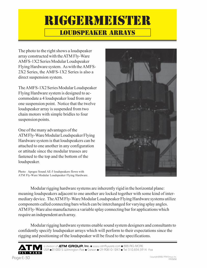
The photo to the right shows a loudspeakerarray constructed with the ATM Fly-WareAMFS-1X2 Series Modular LoudspeakerFlying Hardware system. As with the AMFS-2X2 Series, the AMFS-1X2 Series is also adirect suspension system.
The AMFS-1X2 Series Modular LoudspeakerFlying Hardware system is designed to ac-commodate a 4 loudspeaker load from anyone suspension point. Notice that the twelveloudspeaker array is suspended from twochain motors with simple bridles to foursuspension points.
One of the many advantages of theATM Fly-Ware Modular Loudspeaker FlyingHardware system is that loudspeakers can beattached to one another in any configurationor attitude since the modular trusses arefastened to the top and the bottom of theloudspeaker.
Photo: Apogee Sound AE-5 loudspeakers flown withATM Fly-Ware Modular Loudspeaker Flying Hardware.
Modular rigging hardware systems are inherently rigid in the horizontal plane:meaning loudspeakers adjacent to one another are locked together with some kind of inter-mediary device. The ATM Fly-Ware Modular Loudspeaker Flying Hardware systems utilizecomponents called connecting bars which can be interchanged for varying splay angles.ATM Fly-Ware also manufactures a variable splay connecting bar for applications whichrequire an independent arch array.
Modular rigging hardware systems enable sound system designers and consultants toconfidently specify loudspeaker arrays which will perform to their expectations since therigging and positioning of the loudspeaker will be fixed to the specifications.
LOUDSPEAKER ARRAYS
RIGGERMEISTER
a division of , Inc. ! www.atmflyware.com ! 888.RIG.MOREUSA ! 21000 S Wilmington Ave ! Carson ! CA 90810-1247 ! Tel 310.834.5914 Fax 310.834.3042
Page E-31Copyright 2002, ATM Group, Inc.199 05252
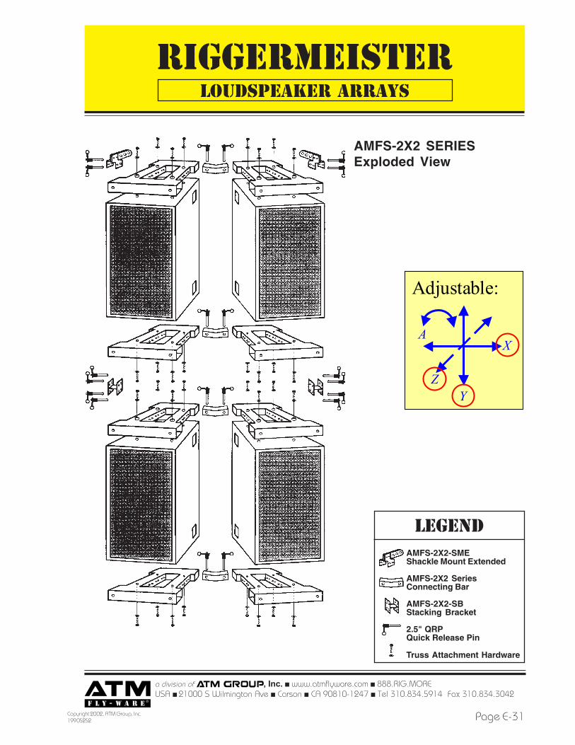
AMFS-2X2 SERIESExploded View
AMFS-2X2-SMEShackle Mount Extended
AMFS-2X2 SeriesConnecting Bar
AMFS-2X2-SBStacking Bracket
2.5" QRPQuick Release Pin
Truss Attachment Hardware
LEGEND
LOUDSPEAKER ARRAYS
Adjustable:
X
YZ
A
RIGGERMEISTER
a division of , Inc. ! www.atmflyware.com ! 888.RIG.MOREUSA ! 21000 S Wilmington Ave ! Carson ! CA 90810-1247 ! Tel 310.834.5914 Fax
Copyright 2002, ATM Group, Inc.199 05252Page E-32
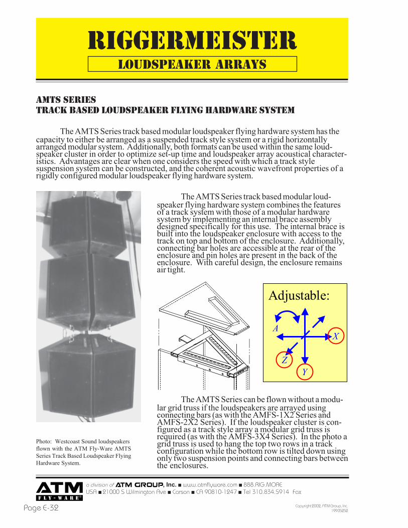
AMTS SERIESTRACK BASED LOUDSPEAKER FLYING HARDWARE SYSTEM
The AMTS Series track based modular loudspeaker flying hardware system has thecapacity to either be arranged as a suspended track style system or a rigid horizontallyarranged modular system. Additionally, both formats can be used within the same loud-speaker cluster in order to optimize set-up time and loudspeaker array acoustical character-istics. Advantages are clear when one considers the speed with which a track stylesuspension system can be constructed, and the coherent acoustic wavefront properties of arigidly configured modular loudspeaker flying hardware system.
The AMTS Series track based modular loud-speaker flying hardware system combines the featuresof a track system with those of a modular hardwaresystem by implementing an internal brace assemblydesigned specifically for this use. The internal brace isbuilt into the loudspeaker enclosure with access to thetrack on top and bottom of the enclosure. Additionally,connecting bar holes are accessible at the rear of theenclosure and pin holes are present in the back of theenclosure. With careful design, the enclosure remainsair tight.
Photo: Westcoast Sound loudspeakersflown with the ATM Fly-Ware AMTSSeries Track Based Loudspeaker FlyingHardware System.
The AMTS Series can be flown without a modu-lar grid truss if the loudspeakers are arrayed usingconnecting bars (as with the AMFS-1X2 Series andAMFS-2X2 Series). If the loudspeaker cluster is con-figured as a track style array a modular grid truss isrequired (as with the AMFS-3X4 Series). In the photo agrid truss is used to hang the top two rows in a trackconfiguration while the bottom row is tilted down usingonly two suspension points and connecting bars betweenthe enclosures.
LOUDSPEAKER ARRAYS
Adjustable:
X
YZ
A
RIGGERMEISTER
a division of , Inc. ! www.atmflyware.com ! 888.RIG.MOREUSA ! 21000 S Wilmington Ave ! Carson ! CA 90810-1247 ! Tel 310.834.5914 Fax 310.834.3042
Page E-33Copyright 2002, ATM Group, Inc.199 05252
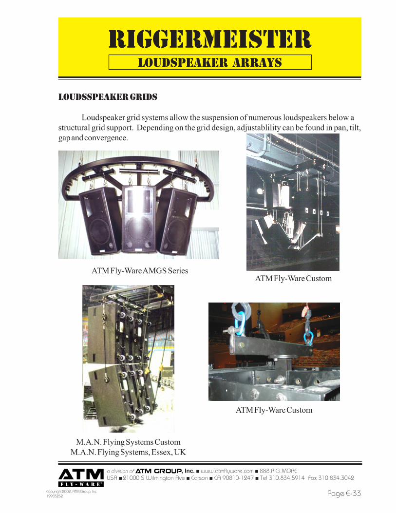
loudsSPEAKER GRIDs
Loudspeaker grid systems allow the suspension of numerous loudspeakers below astructural grid support. Depending on the grid design, adjustablility can be found in pan, tilt,gap and convergence.
LOUDSPEAKER ARRAYS
ATM Fly-Ware AMGS Series
M.A.N. Flying Systems CustomM.A.N. Flying Systems, Essex, UK
ATM Fly-Ware Custom
ATM Fly-Ware Custom

RIGGERMEISTER
a division of , Inc. ! www.atmflyware.com ! 888.RIG.MOREUSA ! 21000 S Wilmington Ave ! Carson ! CA 90810-1247 ! Tel 310.834.5914 Fax
Copyright 2002, ATM Group, Inc.199 05252Page E-34
AFGS SERIESMODULAR LOUDSPEAKER GRID FLYING HARDWARE SYSTEM
The AFGS Series is comprised components which act together to provide the enduser with a safe and efficient permanent support grid which is rated for overhead suspen-sion. Several grid sizes are available to suit a multitude of permanent installation variablesand loudspeaker enclosure designs.
The modularity of the AFGS Series modularloudspeaker grid flying hardware system enables theuser to attach a number of loudspeakers as may benecessary for the design. This is achieved by providing astructural grid framework into which few or severalspokes can be inserted. The spokes then act as theattachment point for loudspeaker suspension beamswhich are available in several widths. Since everythingis designed to be modular, the installer is able to as-semble the grid in the configuration that will work bestfor the application; even if the loudspeaker typeschange within the loudspeaker cluster. The AFGS Serieswill also satisfy many applications in which non-en-closed horns and various rectangular enclosures need tobe suspended.
The AFGS Series modularloudspeaker grid flying hardwaresystem is designed to accommodateloudspeaker enclosure horizontalaiming angles from 00 to 1800 andvertical tilt angles as radical as neces-sary to meet cluster specifications.The grid framework is designed as acomplete 1/2 circle, so loudspeakeracoustic wavefront alignment can bemaintained. If necessary, two grids canbe attached together to form a com-pletely circular array.
LOUDSPEAKER ARRAYS
Adjustable:
X
YZ
A
RIGGERMEISTER
a division of , Inc. ! www.atmflyware.com ! 888.RIG.MOREUSA ! 21000 S Wilmington Ave ! Carson ! CA 90810-1247 ! Tel 310.834.5914 Fax 310.834.3042
Page E-35Copyright 2002, ATM Group, Inc.199 05252
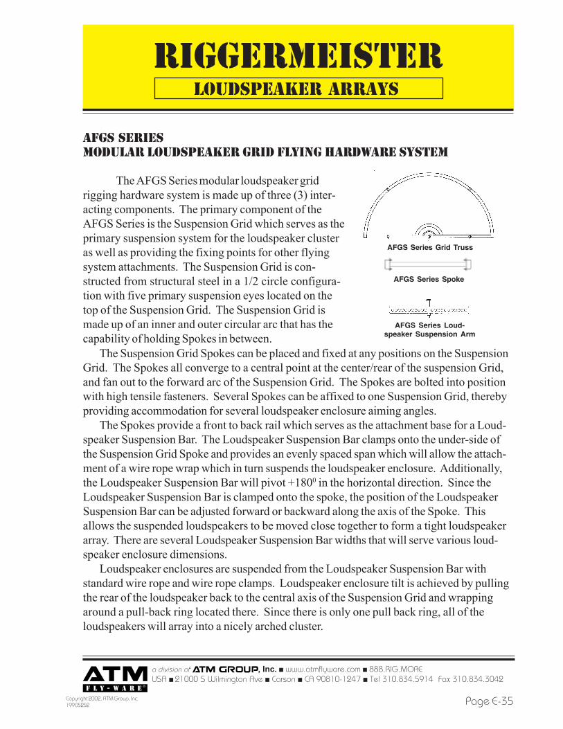
AfGS SERIESMODULAR LOUDSPEAKER GRID FLYING HARDWARE SYSTEM
The AFGS Series modular loudspeaker gridrigging hardware system is made up of three (3) inter-acting components. The primary component of theAFGS Series is the Suspension Grid which serves as theprimary suspension system for the loudspeaker clusteras well as providing the fixing points for other flyingsystem attachments. The Suspension Grid is con-structed from structural steel in a 1/2 circle configura-tion with five primary suspension eyes located on thetop of the Suspension Grid. The Suspension Grid ismade up of an inner and outer circular arc that has thecapability of holding Spokes in between.
The Suspension Grid Spokes can be placed and fixed at any positions on the SuspensionGrid. The Spokes all converge to a central point at the center/rear of the suspension Grid,and fan out to the forward arc of the Suspension Grid. The Spokes are bolted into positionwith high tensile fasteners. Several Spokes can be affixed to one Suspension Grid, therebyproviding accommodation for several loudspeaker enclosure aiming angles.
The Spokes provide a front to back rail which serves as the attachment base for a Loud-speaker Suspension Bar. The Loudspeaker Suspension Bar clamps onto the under-side ofthe Suspension Grid Spoke and provides an evenly spaced span which will allow the attach-ment of a wire rope wrap which in turn suspends the loudspeaker enclosure. Additionally,the Loudspeaker Suspension Bar will pivot +1800 in the horizontal direction. Since theLoudspeaker Suspension Bar is clamped onto the spoke, the position of the LoudspeakerSuspension Bar can be adjusted forward or backward along the axis of the Spoke. Thisallows the suspended loudspeakers to be moved close together to form a tight loudspeakerarray. There are several Loudspeaker Suspension Bar widths that will serve various loud-speaker enclosure dimensions.
Loudspeaker enclosures are suspended from the Loudspeaker Suspension Bar withstandard wire rope and wire rope clamps. Loudspeaker enclosure tilt is achieved by pullingthe rear of the loudspeaker back to the central axis of the Suspension Grid and wrappingaround a pull-back ring located there. Since there is only one pull back ring, all of theloudspeakers will array into a nicely arched cluster.
AFGS Series Spoke
AFGS Series Loud-speaker Suspension Arm
AFGS Series Grid Truss
LOUDSPEAKER ARRAYS
RIGGERMEISTER
a division of , Inc. ! www.atmflyware.com ! 888.RIG.MOREUSA ! 21000 S Wilmington Ave ! Carson ! CA 90810-1247 ! Tel 310.834.5914 Fax
Copyright 2002, ATM Group, Inc.199 05252Page E-36
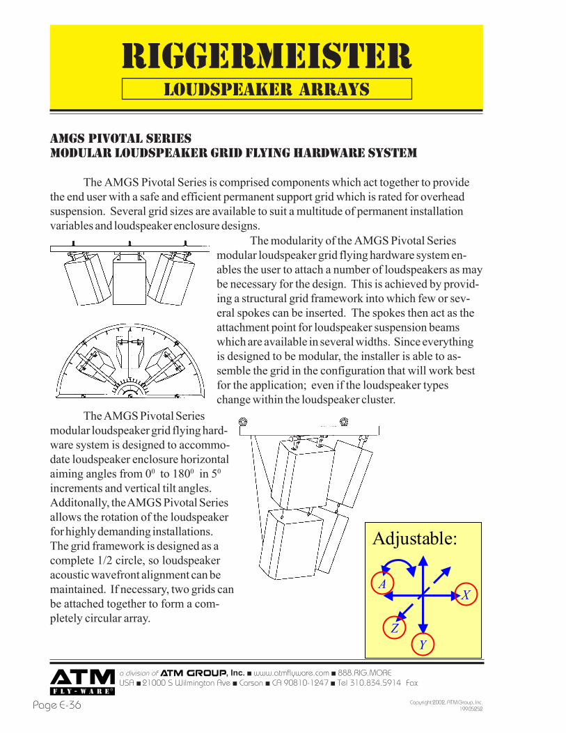
AmGS pivotal SERIESMODULAR LOUDSPEAKER GRID FLYING HARDWARE SYSTEM
The AMGS Pivotal Series is comprised components which act together to providethe end user with a safe and efficient permanent support grid which is rated for overheadsuspension. Several grid sizes are available to suit a multitude of permanent installationvariables and loudspeaker enclosure designs.
The modularity of the AMGS Pivotal Seriesmodular loudspeaker grid flying hardware system en-ables the user to attach a number of loudspeakers as maybe necessary for the design. This is achieved by provid-ing a structural grid framework into which few or sev-eral spokes can be inserted. The spokes then act as theattachment point for loudspeaker suspension beamswhich are available in several widths. Since everythingis designed to be modular, the installer is able to as-semble the grid in the configuration that will work bestfor the application; even if the loudspeaker typeschange within the loudspeaker cluster.
The AMGS Pivotal Seriesmodular loudspeaker grid flying hard-ware system is designed to accommo-date loudspeaker enclosure horizontalaiming angles from 00 to 1800 in 50
increments and vertical tilt angles.Additonally, the AMGS Pivotal Seriesallows the rotation of the loudspeakerfor highly demanding installations.The grid framework is designed as acomplete 1/2 circle, so loudspeakeracoustic wavefront alignment can bemaintained. If necessary, two grids canbe attached together to form a com-pletely circular array.
LOUDSPEAKER ARRAYS
Adjustable:
X
YZ
A
RIGGERMEISTER
a division of , Inc. ! www.atmflyware.com ! 888.RIG.MOREUSA ! 21000 S Wilmington Ave ! Carson ! CA 90810-1247 ! Tel 310.834.5914 Fax 310.834.3042
Page E-37Copyright 2002, ATM Group, Inc.199 05252
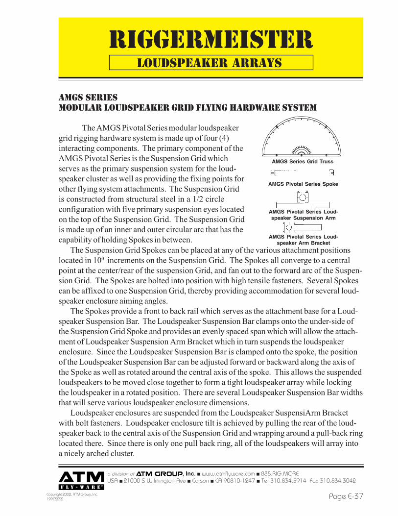
AMGS SERIESMODULAR LOUDSPEAKER GRID FLYING HARDWARE SYSTEM
The AMGS Pivotal Series modular loudspeakergrid rigging hardware system is made up of four (4)interacting components. The primary component of theAMGS Pivotal Series is the Suspension Grid whichserves as the primary suspension system for the loud-speaker cluster as well as providing the fixing points forother flying system attachments. The Suspension Gridis constructed from structural steel in a 1/2 circleconfiguration with five primary suspension eyes locatedon the top of the Suspension Grid. The Suspension Gridis made up of an inner and outer circular arc that has thecapability of holding Spokes in between.
The Suspension Grid Spokes can be placed at any of the various attachment positionslocated in 100 increments on the Suspension Grid. The Spokes all converge to a centralpoint at the center/rear of the suspension Grid, and fan out to the forward arc of the Suspen-sion Grid. The Spokes are bolted into position with high tensile fasteners. Several Spokescan be affixed to one Suspension Grid, thereby providing accommodation for several loud-speaker enclosure aiming angles.
The Spokes provide a front to back rail which serves as the attachment base for a Loud-speaker Suspension Bar. The Loudspeaker Suspension Bar clamps onto the under-side ofthe Suspension Grid Spoke and provides an evenly spaced span which will allow the attach-ment of Loudspeaker Suspension Arm Bracket which in turn suspends the loudspeakerenclosure. Since the Loudspeaker Suspension Bar is clamped onto the spoke, the positionof the Loudspeaker Suspension Bar can be adjusted forward or backward along the axis ofthe Spoke as well as rotated around the central axis of the spoke. This allows the suspendedloudspeakers to be moved close together to form a tight loudspeaker array while lockingthe loudspeaker in a rotated position. There are several Loudspeaker Suspension Bar widthsthat will serve various loudspeaker enclosure dimensions.
Loudspeaker enclosures are suspended from the Loudspeaker SuspensiArm Bracketwith bolt fasteners. Loudspeaker enclosure tilt is achieved by pulling the rear of the loud-speaker back to the central axis of the Suspension Grid and wrapping around a pull-back ringlocated there. Since there is only one pull back ring, all of the loudspeakers will array intoa nicely arched cluster.
AMGS Pivotal Series Spoke
AMGS Pivotal Series Loud-speaker Suspension Arm
AMGS Pivotal Series Loud-speaker Arm Bracket
AMGS Series Grid Truss
LOUDSPEAKER ARRAYS