rigging and installation instructions for single piece and ...€¦ · rigging and installation...
TRANSCRIPT

Rigging and Installation Instructions for Single Piece and Multiple Piece Energy Recovery Plenums
Due to the custom design and build nature of Loren Cook equipment these instructions are given as general information and are not model specific.
This discussion is broken down into five separate sections of consideration for setting a single or multiple piece Energy Recovery Plenum. These five areas are as follows:
Section 1.0: Pre-Lift considerations
Section 2.0: Receiving of the equipment Section 3.0: Rigging of the equipment Section 4.0: Assembly of the sections Section 5.0: Finish work for the Installation
Section 6.0: Installation of Extended Exhaust Porch
Section 7.0: Recommended Tools
1.0 Pre-Lift Considerations
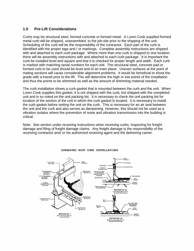
Curbs may be structural steel, formed concrete or formed metal. A Loren Cook supplied formed metal curb will be shipped, unassembled, to the job-site prior to the shipping of the unit. Scheduling of the curb will be the responsibility of the contractor. Each part of the curb is identified with the proper tags and / or markings. Complete assembly instructions are shipped with and attached to each curb package. Where more than one curb is shipped to one location, there will be assembly instructions with and attached to each curb package. It is important the curb be installed level and square and that it is checked for proper length and width. Each curb is marked with matching serial numbers for each unit. The structural steel, concrete pad or formed curb to be used should be level and of an even plane. Uneven surfaces at the point of mating sections will cause considerable alignment problems. It would be beneficial to shoot the grade with a transit prior to the lift. This will determine the high or low points of the installation and thus the points to be shimmed as well as the amount of shimming material needed.
The curb installation shows a curb gasket that is mounted between the curb and the unit. When Loren Cook supplies this gasket, it is not shipped with the curb, but shipped with the completed unit and is so noted on the unit packing list. It is necessary to check the unit packing list for location of the section of the unit in which the curb gasket is located. It is necessary to install the curb gasket before setting the unit on the curb. This is necessary for an air seal between the unit and the curb and also serves as dampening. However, this should not be used as a vibration isolator where the prevention of noise and vibration transmission into the building is critical. Note: See section under receiving instructions when receiving curbs, inspecting for freight damage and filing of freight damage claims. Any freight damage is the responsibility of the receiving contractor and/ or his authorized receiving agent and the delivering carrier.
2.0: Receiving of the Equipment
Most equipment delivered is shipped FOB Factory. Once the equipment is loaded on the trailer, it ownership and responsibility transfers to the purchaser. The equipment is considered delivered when the bill of lading is signed. Receiving the equipment and all of the “Shipped Loose” components is the responsibility of the party signing the bill of lading presented by the trucker. Prior to signing for the equipment, make an inspection of its physical condition and also take an inventory of the listed “shipped loose” items. Should there be damaged or missing items, note them on the bill of lading in the presence of the delivering agent of the carrier and contact the factory immediately. If the decision is made by the contractor or representative agent to accept the equipment it becomes the responsibility of the accepting party to file the freight claim with the carrier in accordance with ICC regulations. It will also be the responsibility of the contractor to ensure the equipment is repaired to the satisfaction of Loren Cook in order to validate the warranty on the equipment. Proper handling of the equipment is mandatory during unloading and setting it into position.
Note: If equipment is not set in its permanent position and is stored on the ground or other unleveled area, proper provisions must be taken for supporting and protecting the equipment. See section for both short term and long term storage.
Shipped Loose Parts:
1. Check the packing list for the list of shipped loose parts. 2. Packing list will note how many and what type of parts. 3. Packing list will note in what section of the unit and where each “shipped loose part”
is located. 4. All air filters are shipped as loose parts. Small rain hoods will be inside the units.
Large rain hoods will be outside the unit and so noted on packing list. Storage 2.1.1 Short-Term Storage Short-term storage is considered six (6) months or less from date shipment. Storage maintenance during this time period is usually, but not necessarily, limited to the following: A. Make sure the equipment is received and unloaded and set in position per guidelines listed
under “Rigging”. B. Make sure all access doors are tightly closed and that all access openings into the unit are
sealed, such as air supply and air return openings, pipe chase openings, fresh air openings, exhaust air openings, electrical connections openings and other access openings of the unit’s cabinet that may permit entry of snow, ice, rain water, dust, dirt, mud and other construction debris, or birds and rodents that may enter the interior of the unit.
C. The unit must also be protected when setting on the ground level to prevent damage to the exterior of the cabinet by construction vehicles and or personnel.
2.1.2 Long-Term Storage Long-term storage is considered to be any period longer than six (6) months from date of shipment. If long-term storage is anticipated, contact the Loren Cook sales office at time of order entry for the proper instruction for long-term storage. It is mandatory that a detailed record be maintained during this long-term storage period, such as, but not limited to, proper sealing of the cabinet, rotation of the blowers and bearings and protection of all motors from moisture. Note: Under certain conditions, it may be necessary to remove the motors from the unit and/or add heat to the motor. This record must be available to Loren Cook should a failure occur during the warranty period. There is a time limit of one year from date of shipment that any unit may be kept in long-term storage. At the end of the one year period, the unit must be in operation. Note: Failure to perform the long-term storage requirements and properly log these required
procedures will void the warranty. 3.0 Rigging the Equipment Decide which section of the equipment that would be most advantageous to set first. You may need to consult the rigger in this decision. Items to be considered would be the reach of the pick, configuration of the building and obstructions on the roof. It is important that an experienced and reliable rigger be selected to handle unloading and final placement of the equipment. Weight of the unit or of its individual sections is the key consideration. This will determine the size of the crane needed to execute the lift. The rigger should have spreader bars capable of spanning both the width and length of the equipment. The rigging should employ some method that allows self-leveling of the load. All of the cables tied to the equipment should be reasonable confirmed to have the same stress as the section being lifted. An imbalance or unleveled lift will damage piping and components installed in the equipment and will not allow proper alignment of the sections as they are lowered into position.
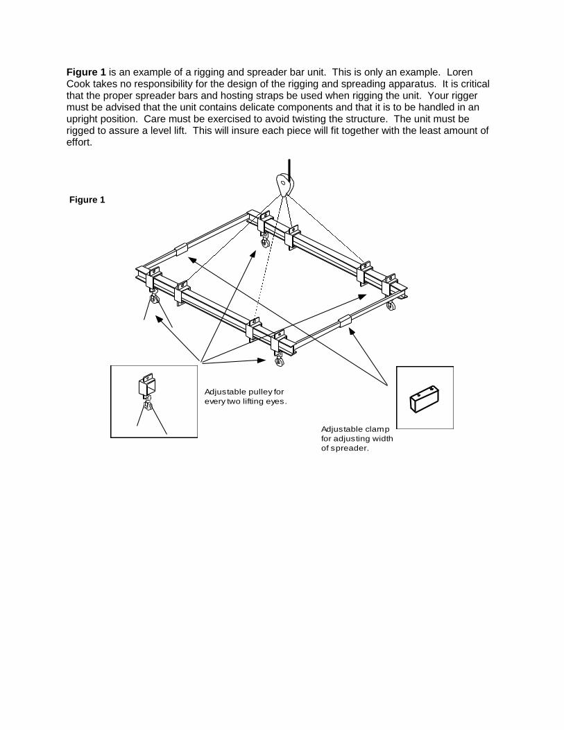
Adjustable pulley for
every two lifting eyes.
Adjustable clamp
for adjusting width
of spreader.
Figure 1 is an example of a rigging and spreader bar unit. This is only an example. Loren Cook takes no responsibility for the design of the rigging and spreading apparatus. It is critical that the proper spreader bars and hosting straps be used when rigging the unit. Your rigger must be advised that the unit contains delicate components and that it is to be handled in an upright position. Care must be exercised to avoid twisting the structure. The unit must be rigged to assure a level lift. This will insure each piece will fit together with the least amount of effort.
Figure 1
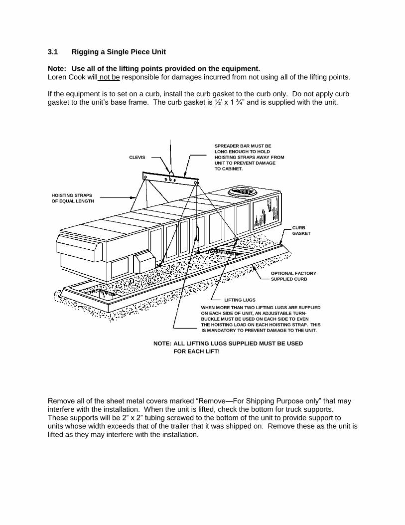
3.1 Rigging a Single Piece Unit Note: Use all of the lifting points provided on the equipment. Loren Cook will not be responsible for damages incurred from not using all of the lifting points. If the equipment is to set on a curb, install the curb gasket to the curb only. Do not apply curb gasket to the unit’s base frame. The curb gasket is ½’ x 1 ¾” and is supplied with the unit.
CLEVIS
HOISTING STRAPS
OF EQUAL LENGTH
SPREADER BAR MUST BE
LONG ENOUGH TO HOLD
HOISTING STRAPS AWAY FROM
UNIT TO PREVENT DAMAGE
TO CABINET.
CURB
GASKET
OPTIONAL FACTORY
SUPPLIED CURB
LIFTING LUGS
WHEN MORE THAN TWO LIFTING LUGS ARE SUPPLIED
ON EACH SIDE OF UNIT, AN ADJUSTABLE TURN-
BUCKLE MUST BE USED ON EACH SIDE TO EVEN
THE HOISTING LOAD ON EACH HOISTING STRAP. THIS
IS MANDATORY TO PREVENT DAMAGE TO THE UNIT.
NOTE: ALL LIFTING LUGS SUPPLIED MUST BE USED
FOR EACH LIFT! Remove all of the sheet metal covers marked “Remove—For Shipping Purpose only” that may interfere with the installation. When the unit is lifted, check the bottom for truck supports. These supports will be 2” x 2” tubing screwed to the bottom of the unit to provide support to units whose width exceeds that of the trailer that it was shipped on. Remove these as the unit is lifted as they may interfere with the installation.
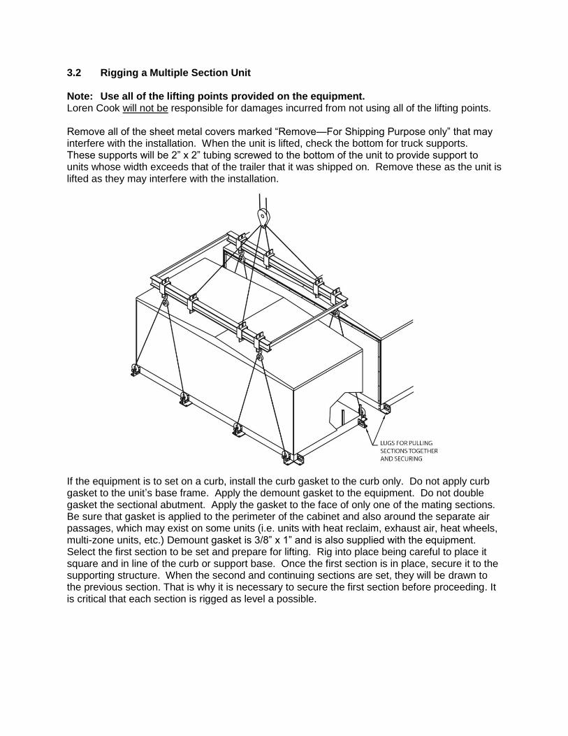
3.2 Rigging a Multiple Section Unit Note: Use all of the lifting points provided on the equipment. Loren Cook will not be responsible for damages incurred from not using all of the lifting points. Remove all of the sheet metal covers marked “Remove—For Shipping Purpose only” that may interfere with the installation. When the unit is lifted, check the bottom for truck supports. These supports will be 2” x 2” tubing screwed to the bottom of the unit to provide support to units whose width exceeds that of the trailer that it was shipped on. Remove these as the unit is lifted as they may interfere with the installation.
If the equipment is to set on a curb, install the curb gasket to the curb only. Do not apply curb gasket to the unit’s base frame. Apply the demount gasket to the equipment. Do not double gasket the sectional abutment. Apply the gasket to the face of only one of the mating sections. Be sure that gasket is applied to the perimeter of the cabinet and also around the separate air passages, which may exist on some units (i.e. units with heat reclaim, exhaust air, heat wheels, multi-zone units, etc.) Demount gasket is 3/8” x 1” and is also supplied with the equipment. Select the first section to be set and prepare for lifting. Rig into place being careful to place it square and in line of the curb or support base. Once the first section is in place, secure it to the supporting structure. When the second and continuing sections are set, they will be drawn to the previous section. That is why it is necessary to secure the first section before proceeding. It is critical that each section is rigged as level a possible.
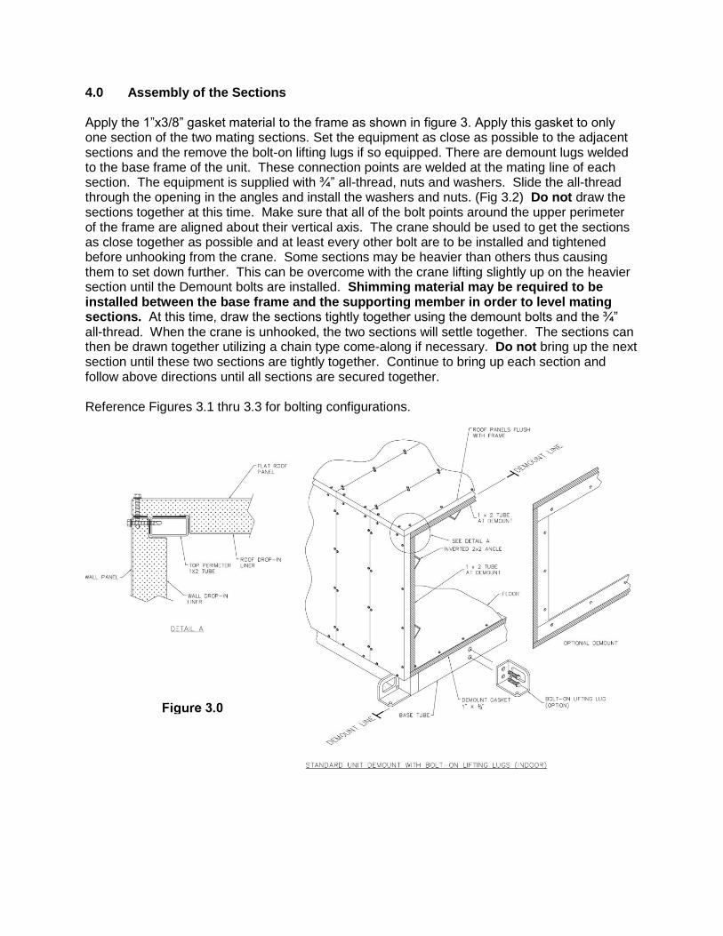
4.0 Assembly of the Sections Apply the 1”x3/8” gasket material to the frame as shown in figure 3. Apply this gasket to only one section of the two mating sections. Set the equipment as close as possible to the adjacent sections and the remove the bolt-on lifting lugs if so equipped. There are demount lugs welded to the base frame of the unit. These connection points are welded at the mating line of each section. The equipment is supplied with ¾” all-thread, nuts and washers. Slide the all-thread through the opening in the angles and install the washers and nuts. (Fig 3.2) Do not draw the sections together at this time. Make sure that all of the bolt points around the upper perimeter of the frame are aligned about their vertical axis. The crane should be used to get the sections as close together as possible and at least every other bolt are to be installed and tightened before unhooking from the crane. Some sections may be heavier than others thus causing them to set down further. This can be overcome with the crane lifting slightly up on the heavier section until the Demount bolts are installed. Shimming material may be required to be installed between the base frame and the supporting member in order to level mating sections. At this time, draw the sections tightly together using the demount bolts and the ¾” all-thread. When the crane is unhooked, the two sections will settle together. The sections can then be drawn together utilizing a chain type come-along if necessary. Do not bring up the next section until these two sections are tightly together. Continue to bring up each section and follow above directions until all sections are secured together. Reference Figures 3.1 thru 3.3 for bolting configurations.
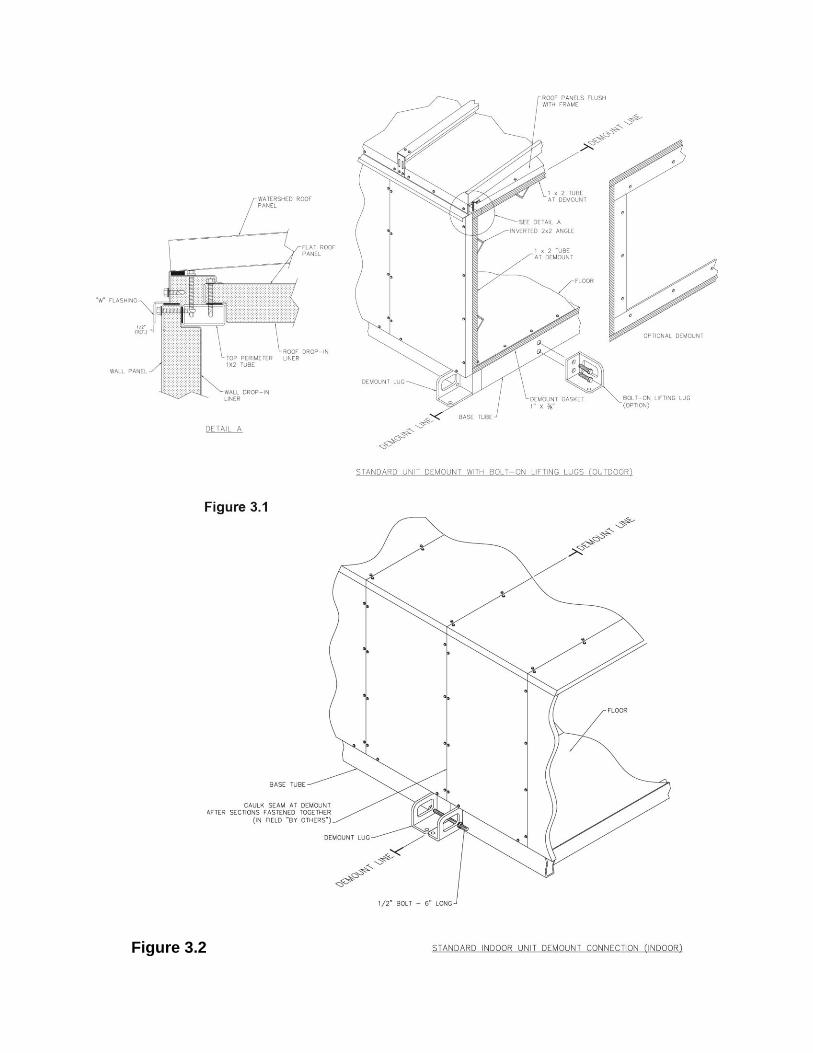
Figure 3.2
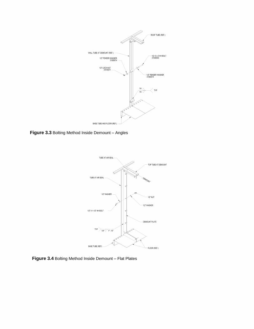
Figure 3.3 Bolting Method Inside Demount – Angles
Figure 3.4 Bolting Method Inside Demount – Flat Plates
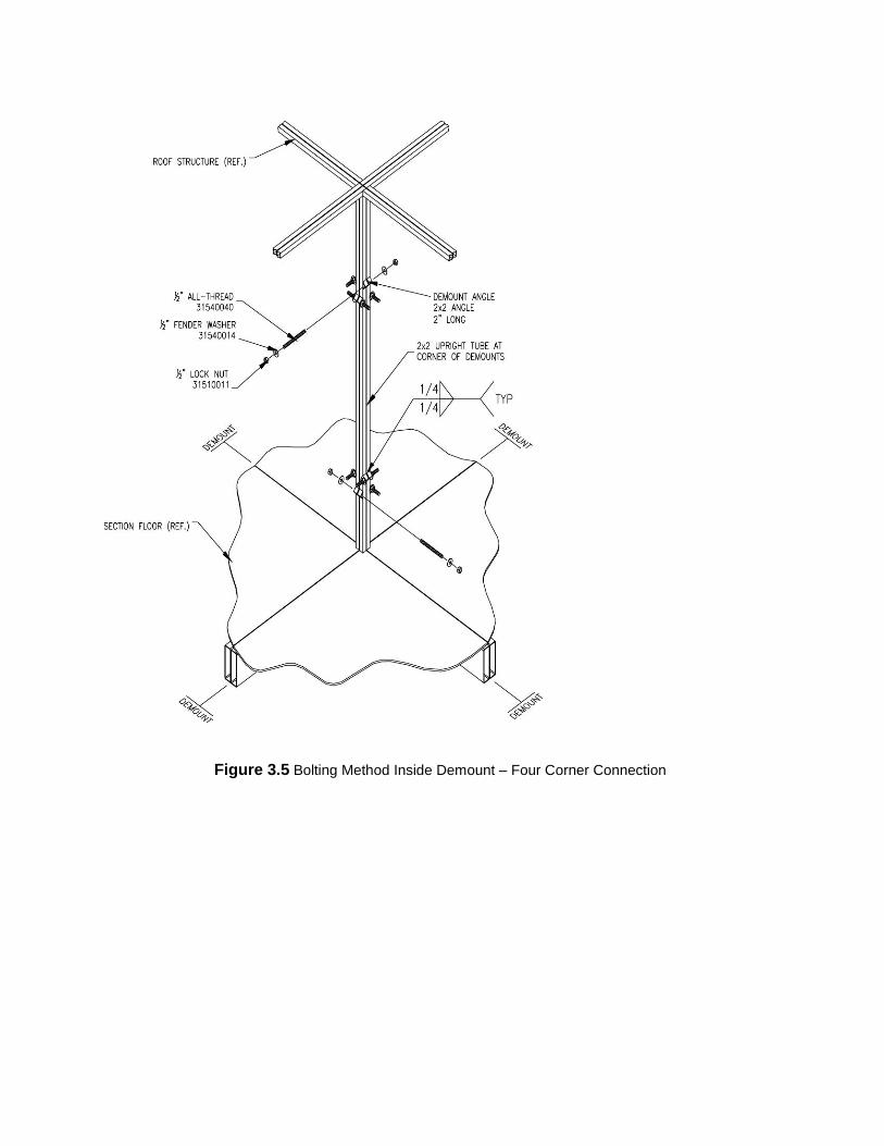
Figure 3.5 Bolting Method Inside Demount – Four Corner Connection
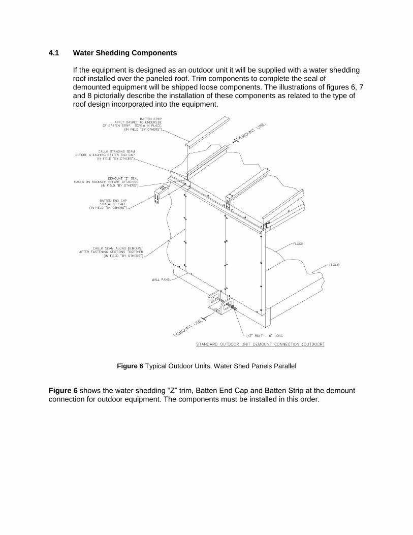
4.1 Water Shedding Components
If the equipment is designed as an outdoor unit it will be supplied with a water shedding roof installed over the paneled roof. Trim components to complete the seal of demounted equipment will be shipped loose components. The illustrations of figures 6, 7 and 8 pictorially describe the installation of these components as related to the type of roof design incorporated into the equipment.
Figure 6 Typical Outdoor Units, Water Shed Panels Parallel
Figure 6 shows the water shedding “Z” trim, Batten End Cap and Batten Strip at the demount connection for outdoor equipment. The components must be installed in this order.
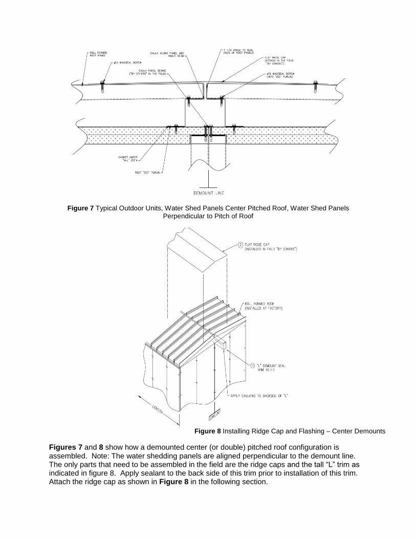
Figure 7 Typical Outdoor Units, Water Shed Panels Center Pitched Roof, Water Shed Panels Perpendicular to Pitch of Roof
Figures 7 and 8 show how a demounted center (or double) pitched roof configuration is assembled. Note: The water shedding panels are aligned perpendicular to the demount line. The only parts that need to be assembled in the field are the ridge caps and the tall “L” trim as indicated in figure 8. Apply sealant to the back side of this trim prior to installation of this trim. Attach the ridge cap as shown in Figure 8 in the following section.
Figure 8 Installing Ridge Cap and Flashing – Center Demounts
5.0 Finish Work for the Installation Once the equipment has been set and completely bolted together, the following finish work must be done to complete the installation: 1. Caulk all demount seams with an RTV silicone clear caulk (not furnished) after the
sections have been secured. 2. Additional RTV silicone caulking should be applied to the interior of the cabinet around
any separate air passages and at the demount joints. 3. Re-caulk if and where caulking has been broken due to rigging or shipment. 4. Check to see that all doors are square. The rigging may sometimes warp the doors out
of alignment. This must be corrected before unit is started. Check all door latches and re-adjust if necessary to maintain a good tight seal.
5.1 Electrical Electrical wiring for controls and internal lighting circuits will require splicing where they cross a demount line on Loren Cook units. A separate numbered terminal strip and conduit is provided for the control wiring and internal lighting circuits, all wires are numbered to match the terminal strips. A short piece of flexible conduit is provided on one side and a terminal box housing the terminal strip is provided on the other side of demount to facilitate assembly. Note: Loren Cook is not responsible for the demount mandated wiring requirements. 5.2 Refrigerant Line and Piping All CW, HW and various black iron piping that crosses a demount will be flanged of union joined. If the pipe is flanged, a flange gasket kit is provided. Check the packing list for the location of the flange kits. Note: Loren Cook is not responsible for the demount mandated piping requirement. Loren
Cook is not responsible for quality of workmanship during the pipe reconnection process or warranty concerns associated with lack of proper piping techniques during this process.
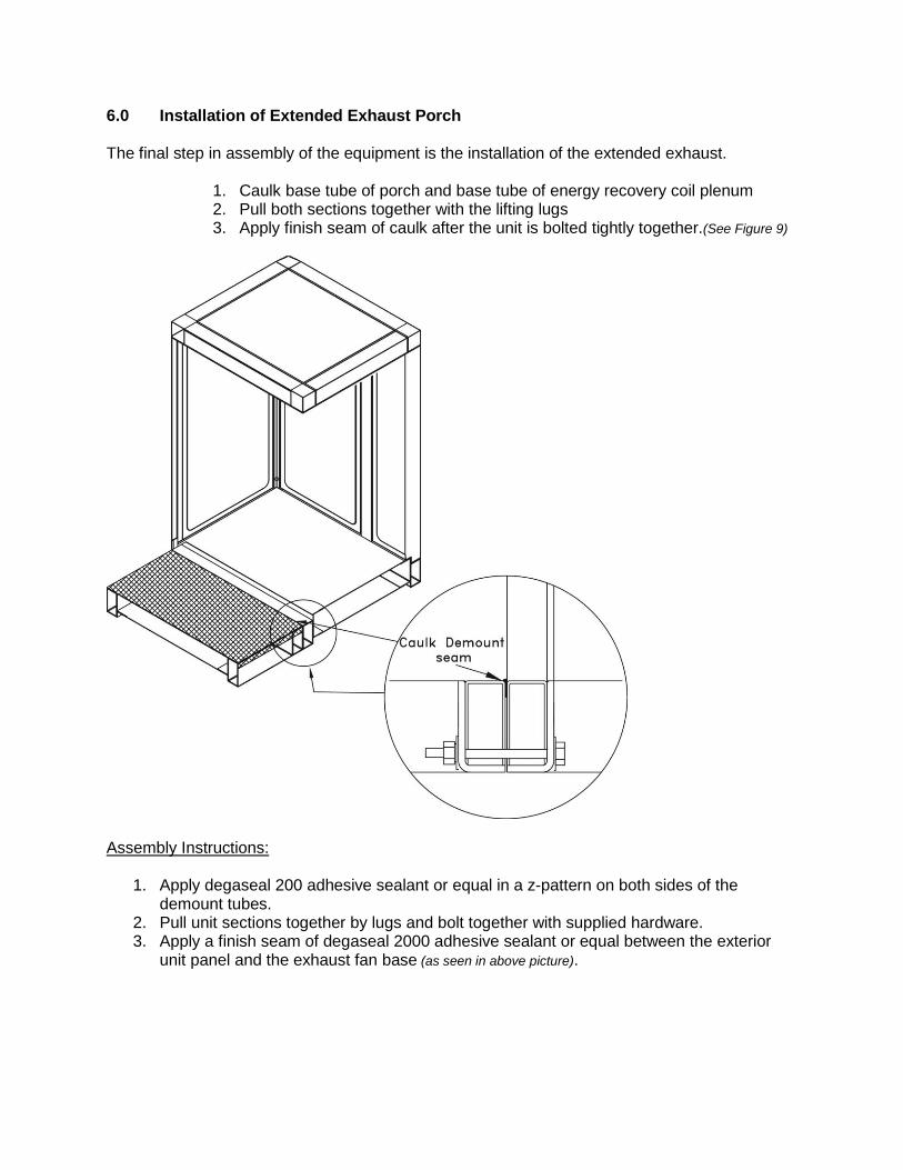
6.0 Installation of Extended Exhaust Porch The final step in assembly of the equipment is the installation of the extended exhaust.
1. Caulk base tube of porch and base tube of energy recovery coil plenum 2. Pull both sections together with the lifting lugs 3. Apply finish seam of caulk after the unit is bolted tightly together.(See Figure 9)
Assembly Instructions:
1. Apply degaseal 200 adhesive sealant or equal in a z-pattern on both sides of the demount tubes.
2. Pull unit sections together by lugs and bolt together with supplied hardware. 3. Apply a finish seam of degaseal 2000 adhesive sealant or equal between the exterior
unit panel and the exhaust fan base (as seen in above picture).
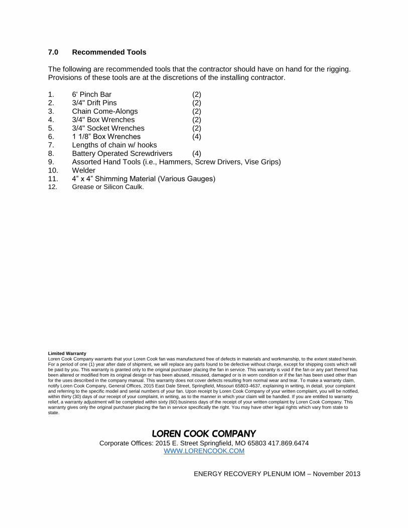
7.0 Recommended Tools The following are recommended tools that the contractor should have on hand for the rigging. Provisions of these tools are at the discretions of the installing contractor. 1. 6' Pinch Bar (2) 2. 3/4" Drift Pins (2) 3. Chain Come-Alongs (2) 4. 3/4" Box Wrenches (2) 5. 3/4" Socket Wrenches (2) 6. 1 1/8” Box Wrenches (4) 7. Lengths of chain w/ hooks 8. Battery Operated Screwdrivers (4) 9. Assorted Hand Tools (i.e., Hammers, Screw Drivers, Vise Grips) 10. Welder 11. 4” x 4” Shimming Material (Various Gauges) 12. Grease or Silicon Caulk.
Limited Warranty Loren Cook Company warrants that your Loren Cook fan was manufactured free of defects in materials and workmanship, to the extent stated herein. For a period of one (1) year after date of shipment, we will replace any parts found to be defective without charge, except for shipping costs which will be paid by you. This warranty is granted only to the original purchaser placing the fan in service. This warranty is void if the fan or any part thereof has been altered or modified from its original design or has been abused, misused, damaged or is in worn condition or if the fan has been used other than for the uses described in the company manual. This warranty does not cover defects resulting from normal wear and tear. To make a warranty claim, notify Loren Cook Company, General Offices, 2015 East Dale Street, Springfield, Missouri 65803-4637, explaining in writing, in detail, your complaint and referring to the specific model and serial numbers of your fan. Upon receipt by Loren Cook Company of your written complaint, you will be notified, within thirty (30) days of our receipt of your complaint, in writing, as to the manner in which your claim will be handled. If you are entitled to warranty relief, a warranty adjustment will be completed within sixty (60) business days of the receipt of your written complaint by Loren Cook Company. This warranty gives only the original purchaser placing the fan in service specifically the right. You may have other legal rights which vary from state to state.
LOREN COOK COMPANY Corporate Offices: 2015 E. Street Springfield, MO 65803 417.869.6474
WWW.LORENCOOK.COM
ENERGY RECOVERY PLENUM IOM – November 2013