rigging in the rai
TRANSCRIPT

Rigging in the RAI Guidelines for Riggers
RAI Amsterdam
Document name: Rigging in de RAI EN
Version 1.6.1
2016

Rigging in the RAI - 1 - Version 1.6 English
2016
Revision version 1.6 by Xander ten Dolle
Revision date / initials 1 – 10-2016
Released by Herman Nietvelt
Date / initials 1 – 10-2016
Document title Rigging in the RAI
Guidelines for riggers
Document name Rigging in the RAI EN – version 1.6
Status Definitive
Date 01-10-2016
Author
Supervision
Thomas Sluiter – Xander ten Dolle
Herman Nietvelt
This document is based
on the following sources
Document toelaatbare belastingen RAI Amsterdam, by Bouwspoor,
October 2005.
Rigging hallen 1 t/m 5. Berekening toelaatbare lasten – Revisie A.
9T3029.A0/9S1604C14/R004A/BDer/Amst, 28 November 2008.
Rigging hallen 6 t/m 11. Aanvullende berekening toelaatbare lasten –
Revisie A. 9T3029.A0/R001A/BDer/Amst, 13 March 2009.
Rigging dakvlak entree C en entree F. Aanvullende berekening
toelaatbare lasten – Revisie A. 9T3029.A0/R002A/RC/BDer/Amst, 14
August 2008.
Combinatie rigging en carrousels. Toelaatbare lasten aan dakconstructie.
9T3029.D0/R005/BDer/Amst, 10 December 2008.
Rigging entreegebied Europahal. Aanvullende berekening toelaatbare
lasten. 9T3029.A0/R006/RC/Amst, 29 April 2009
NPR 8020-10
NPR 8020-13 (Draft March 2009)
Machine Directive [Machinerichtlijn] 98/37/EC
Previous versions
rigginginderai260208 - Rigging in de RAI Versie 1.0
(26 Februari 2008) Published
rigginginderaiNL - Versie 1.2
(3 september 2008) Published
rigginginderaiNL – Versie 1.3
(8 June 2009) Published
rigginginderaiNL – Versie 1.4
(14 August 2014) Published
rigginginderaiNL – Versie 1.4
(1 July 2015) Published

Rigging in the RAI - 2 - Version 1.6 English
2016
INDEX
1 INTRODUCTION 3
2 RIGGING GUIDELINES 4
3 ENTRANCE C: CANOPY 6
4 HOLLAND TERRACE 8
5 HOLLAND LOUNGE 10
6 ENTRANCE F 12
7 PARK FOYER 15
8 ENTRANCE K 17
9 HALL 1 19
10 HALL 2 22
11 HALL 3 24
12 HALL 4 27
13 HALL 5 30
14 HALL 6 32
15 HALL 7 35
16 HALL 8 38
17 HALL 9 41
18 HALL 10 43
19 HALL 11 46
20 HALL 12 49
21 HALL 13 52
22 AUDITORIUM LOUNGE AND ONYX LOUNGE 55
23 UPPER LOUNGE AND EMERALD LOUNGE 57
24 DIAMOND LOUNGE 59
25 EUROPE FOYER 1 AND 2 61
26 ROOM G102 63
APPENDIX I: REQUIREMENTS FOR THE RIGGING PLAN 65
APPENDIX II: RAI LIVE RESTRICTIONS HALLS 8, 10, 11 AND 12 66

Rigging in the RAI - 3 - Version 1.6 English
2016
1 INTRODUCTION
This booklet shows where and under what conditions rigging is possible in RAI Amsterdam. For
each part of the RAI we explain the locations for rigging and the maximum load per suspension
point for both vertical rigging (straights) as well as multi-point bridles (bridles).
To set up a rig in our complex, the rigging party must first send a rigging plan to the RAI Account
Manager of the relevant event or trade show four weeks before the beginning of the event or
trade show. This document describes what the rigging plan must look like. Each rigging plan will
then be evaluated against the criteria specified in this document. You will receive an official
response from the RAI within five working days, after which possible adjustments can be made.
An agreement on the definite version should be made two weeks before the start of the event or
trade show.
Below is a floor plan of RAI Amsterdam (Figure 1). Each hall, entrance area and foyer has its
own chapter, provided that rigging is possible.
Figure 1: Floor plan of RAI Amsterdam
Tips: Always find out which is the latest version of this document.

Rigging in the RAI - 4 - Version 1.6 English
2016
2 RIGGING GUIDELINES
The following applies when making any decisions: safety first! The following conditions must be
met in order to set up rigging in the RAI:
Company and personnel certification 1. Rigging may only be taken on by VCA*, VCA** or Oshas 18001 certified companies. 2. Each rigger present must:
o carry a valid VCA certificate (VCA-B or VOL-VCA for operations managers). o be able to prove that he holds an Elementaire Hijstechniek in de Entertainment Industrie
certificate or a variation of this such as a National Rigging Certificate (UK), Arena Rigging Certificate from ETCP (USA), Rigstar Rigging certificate (USA), or a relevant VLPT rigging diploma (GER).
o If a truck-mounted work platform is used, the operator must have the correct certificate. The rigger is responsible for ensuring that no third parties are present in his work zone.
o Anyone who uses a truck-mounted work platform must wear a full-body safety harness (EN361) attached to the platform by means of a lanyard (EN355).
o People (grounders) in the vicinity of the operating scope of the truck-mounted work platform must wear a helmet (EN397).
Requirements for the rigging plan 3. Each rigging party involved must have a rigging plan approved by the RAI. A description of
how the rigging plan must be submitted to the RAI is included in Appendix I. Your RAI Account Manager can also submit a sample rigging plan.
4. Each part of the building described in this document has its own AutoCAD drawing on which the available suspension points are indicated.
5. The maximum permissible load stated in this manual must not be exceeded. 6. For multi-point bridles (bridles), the inside angle must be less than 120 degrees (see Figure
2). 7. The maximum permissible load for multi-point bridles is based on 2-point bridles. For multi-
point bridles, the distribution of force at all points of application must be clearly calculated. 8. Dynamic loads are not permitted without explicit consent from a designer chosen by the
RAI, at the expense of the customer/contractor.
Rigging in practice 9. Rigging must only be carried out in accordance with the plan: any changes must be
discussed with the manager of the Technical Department at the RAI Amsterdam. 10. For some parts of the building, the maximum permissible load is different in case of snow.
The RAI is allowed to arrange for a load which has already been approved to be reduced to an acceptable weight.
11. The roof construction must not be damaged in any way. 12. Fixed elements in the roof (such as lighting fixtures, blinds, blackout mechanisms, drains)
must not be touched during rigging.

Rigging in the RAI - 5 - Version 1.6 English
2016
Use of materials 13. Rigging may only be carried out using materials bearing CE marking.In the case of parties
outside the EU, products must demonstrably fulfil the ASME or an equivalent directive. 14. Materials must have a WLL inscription or label. 15. The maximum permissible load is 0.5 times the (industrial) WLL 16. Materials must be tested at least once a year and it must be possible for the test report to be
produced within 24 hours on request. 17. Materials must be used in accordance with instructions.
Note: At all times the RAI reserves the right to take down the rigging or to arrange for a load
which has already been approved to be reduced (e.g. in case of snowfall) at any time. The
rigging party should be aware that the RAI checks whether the suspension points have been
constructed in accordance with guidelines and the rigging plan. If this is not the case, the RAI is
authorised to reject the rigging. In the event of rejection, the RAI is not liable for any damages
(such as financial damage or damage to image).

Rigging in the RAI - 6 - Version 1.6 English
2016
3 ENTRANCE C: CANOPY
Figure 2: Entrance C : Canopy suspension points
Height of suspension
points
Lower part: 9.50 m
Distance between
suspension points
: 3.75 m
: 3.75 m

Rigging in the RAI - 7 - Version 1.6 English
2016
In Entrance C, vertical rigging is allowed at the locations indicated (see Fout!
Verwijzingsbron niet gevonden.). There are a total of 65 possible suspension points on
the 2-dimensional framework.
Note: The canopy is fitted with a pigeon net which must not be damaged.
Note: Above wind force 6, all rigging must be taken down from the shed roof.
Vertical rigging (straight) Vertical rigging is allowed from the lower part of the 2D framework at the locations indicated. The maximum load per suspension point is 250 kg.
Bridling (bridles) Bridling is not allowed.
Snow If more than 5 centimetres of snow should fall, rigging is not allowed at Entrance C.

Rigging in the RAI - 8 - Version 1.6 English
2016
4 HOLLAND TERRACE
Figure 3: Holland Terrace suspension points
Height of suspension points
Lower part: 9.50 m
Higher part: 6 m
Distance between suspension points
: 3.75 m
: ranges between 2.50 and 4.50 m

Rigging in the RAI - 9 - Version 1.6 English
2016
On the Holland Terrace, vertical rigging is allowed from the eyes in the ceiling. There are a total
of 97 possible suspension points (see Fout! Verwijzingsbron niet gevonden.).
Vertical rigging (straight) On the Red suspension points rigging is allowed from the eyes in the ceiling. On the Blue suspension points rigging is allowed on the beams
Attention: Rigging is not allowed on the round 60 mm tubes between the Blue suspension points.
The maximum load per eye is 250 kg.
Bridling (bridles) Bridling is not allowed.
Snow If more than 5 centimetres of snow should fall, rigging is not allowed on the Holland Terrace.

Rigging in the RAI - 10 - Version 1.6 English
2016
5 HOLLAND LOUNGE
Figure 4: Suspension points in Holland Lounge

Rigging in the RAI - 11 - Version 1.6 English
2016
In the Holland Lounge, vertical rigging is allowed from eyes in the ceiling. There are a total of 9
possible suspension points. (see Fout! Verwijzingsbron niet gevonden.)
Vertical rigging (straight) Vertical rigging is allowed from eyes in the ceiling. The maximum load per eye is 150 kg.
Bridling (bridles) Bridling is not allowed.
Snow If more than 5 centimetres of snow should fall, rigging is not allowed in the Holland Lounge.
Requirements for attachment to the roof construction:
Note:
Before carrying out rigging, (CE and WLL)
certified eye bolts must be fitted. The thread of
the eye bolts is M12.

Rigging in the RAI - 12 - Version 1.6 English
2016
6 ENTRANCE F
Figure 5: Suspension points at Entrance F
Height of suspension points
ground floor
Lower edge of 2D frame: 9.50 m
Steel frame: 11.00 m
2nd floor
Steel frame: 7.50m
Distance between the suspension
points
7.50 m
3.75 m
GF
V1

Rigging in the RAI - 13 - Version 1.6 English
2016
Entrance F consists of a shed roof and a foyer. Vertical rigging is possible at the locations
indicated in Figure 5.
In the shed roof, vertical rigging is possible from the lower part of the 2D and 3D frameworks. In
the foyer, vertical rigging is allowed from the I-frame at less than 50 cm from the 2D framework
Note: The canopy is fitted with a pigeon net which must not be damaged.
Figure 6: 3D model entrance area F
Vertical rigging (straight) The maximum load per suspension point is 200 kg.
Bridling (bridles) Bridling is not allowed.
Snow No restrictions in case of snowfall.
2D framework
3D framework
I-frames
Canopy

Rigging in the RAI - 14 - Version 1.6 English
2016
Requirements for attachment to the roof construction:
Note:
Rigging on the I-frame at less than 50cm
from the 2D framework.
Rigging on 2D framework is not permitted
in connection with lighting fixtures.
< 50 cm

Rigging in the RAI - 15 - Version 1.6 English
2016
7 PARK FOYER
Figure 7: Park Foyer suspension points
Height of suspension points
Height: 5.60 m
Distance between suspension
points
: 7.50 m
: 3.60 m
Note: The distance is different
at the location indicated.
3.10 m
8.31 m
3.10 m
3.10 m

Rigging in the RAI - 16 - Version 1.6 English
2016
In the Park Foyer vertical rigging is permitted from eyes in the ceiling. There are a total of 38
possible suspension points. (see Figure 7)
Vertical rigging (straight) Vertical rigging is allowed from eyes in the ceiling. The maximum load per eye is 150 kg.
Bridling (bridles) Bridling is not allowed.
Snow No restrictions in case of snowfall.

Rigging in the RAI - 17 - Version 1.6 English
2016
8 ENTRANCE K
Figure 8: Suspension points in Entrance K
Em
erg
en
cy E
xit
to b
e a
ccessib
leE
merg
en
cy E
xit
to b
e a
cce
ssib
le
door
to b
e a
ccessib
lefo
r re
achin
g R
AI
Offic
es
Height of suspension points
Height: 7.35 m
Distance between the joints
: 3.00 m
: 3.75 m

Rigging in the RAI - 18 - Version 1.6 English
2016
Vertical rigging is allowed from the eyes in the ceiling in Entrance K. There are a total of 69
possible suspension points. (See Figure 8)
Vertical rigging (straight) Vertical rigging is allowed from the eyes in the ceiling. The maximum load per eye is 250 kg.
Bridling (bridles) Bridling is not allowed.
Snow No restrictions in case of snowfall.

Rigging in the RAI - 19 - Version 1.6 English
2016
9 HALL 1
Figure 9: Suspension points in Hall 1
Height and weight
Use beam clamps in the grey
area.
Use steel slings / baskets in
the white area.
Note: Do not obstruct the
automatic blackout parallel to
the 6th steel frame. Use beam
clamps on the 6th steel frame
between frames 5-6.
1 2 3 4 5 6 7 8 9 10
Note: The pipeline parallel to
the 1st and 10th steel frames
must never be touched. Only
bridles may be suspended from
these frames at an angle of
between 91.6° and 120°.
1 2 3 4 5 6 7 8 9 10

Rigging in the RAI - 20 - Version 1.6 English
2016
In Hall 1, rigging is allowed from the steel frames (see Figure 9). The steel frame connects 39
bow trusses together. Each bow truss has a maximum rigging load of 8,000 kg. The load must
be distributed in accordance with Table 1. With maximum loads there are 480 possible
suspension points.
Figure 10: Steel frame in roof construction of Hall 1
Table 1: Maximum load and distribution of weight in Hall 1 1 / 2 / 3 / 4
On the member On the joint Total weight per
bow truss
Vertical
Maximum 650 kg Maximum 650 kg
8000 kg
Bridling
(bridles)
Max. 300 kg per
bridle and
max. 300 kg vertical
load per member
Max. 650 kg per
bridle and
max. 650 kg vertical
load per joint
Snowfall
(between 5 and 10
cm)
Total weight
restriction per bow
truss
Total weight
restriction per bow
truss
4000 kg
Snowfall
(more than 10 cm)
No rigging possible No rigging possible 0 kg
1 A member is the part of the steel frame between two joints (see Figure 10).
2 A joint is where two parts of the steel frame are connected to the bow truss (see Figure 11).
3 The maximum load may be distributed between one or more suspension points.
4 If a member and an adjacent joint are loaded, the load on the member must be added to the
load on the joint. The total weight must never exceed the maximum load for the joint.
Steel frame
Automatic blackout
Joint (steel)
Member (steel)
Member (beam
clamp)
Joint (steel)

Rigging in the RAI - 21 - Version 1.6 English
2016
Requirements for attachment to the roof construction:
Steel sling at joint.
Beam clamp at joint.
Note: Only 2-point bridles may be suspended from the
1st and 10th steel frames (above the balconies), at an
angle of between 91.6° and 120°.
Note: In order to protect the automatic blackout:
Use a beam clamp on the 5th and 6th steel frame for 2-
point bridles (bridles) between the 6th steel frame.

Rigging in the RAI - 22 - Version 1.6 English
2016
10 Hall 2
Figure 11: Suspension points in Hall 2
h=3,85 mtr. h=3,85 mtr. h=3,85 mtr. h=3,85 mtr.
Hall dimensions
Height: 10.75 m
Length: 88.50 m
Width: 44.35 m
Distance between the joints
: 5.00 m and 10.00 m
: 3.75 m
No suspension point due to
overhead construction

Rigging in the RAI - 23 - Version 1.6 English
2016
In Hall 2, vertical rigging is allowed from the joints of the longitudinal girders. There are a
total of 131 possible suspension points (see Figure 11). The maximum permissible load is
shown in Table 2.
Figure 13: Joints in Hall 2
Table 2: Maximum load and distribution of weight in Hall 2 1 / 2
On the member On the joint
Vertical
13 kg 300 kg
Bridling
(bridles)
Not allowed Not allowed
Snowfall
(more than 5 cm)
No rigging possible No rigging possible
1 A member is the horizontal connection between two joints.
2 If a member and an adjacent joint are loaded, the load on the member must be added to the
load on the joint. The total weight must never exceed the maximum load for the joint.
Requirements for attachment to the roof construction:
Between diagonal and vertical member with jute
protection (burlap).
13 Kg 300 Kg 13 Kg 300 Kg

Rigging in the RAI - 24 - Version 1.6 English
2016
11 Hall 3
Figure 12: Suspension points in Hall 3
Hall dimensions
Higher part: 10.00 m
Lower part: 8.00 m
Distance between the joints
: 5.00 m / 10.00 m
: 3.75 m
Note: In the lower part,
rigging is possible from
the suspension eyes in
the ceiling.

Rigging in the RAI - 25 - Version 1.6 English
2016
In Hall 3, vertical rigging is allowed from the joints of the longitudinal girders. There are a total of
132 possible suspension points (see Figure 12). The maximum permissible load is shown in
table 3.
Figure 13: Joints in Hall 3
Table 3: Maximum load and distribution of weight in Hall 3 1 / 2
On the member On the joint On the suspension
eyes
Vertical
13 kg 300 kg 300 kg
Bridling
(bridles)
Not
allowed Not allowed Not allowed
Snowfall
(more than 5
cm)
No rigging possible No rigging possible No rigging possible
1 A member is the horizontal connection between two joints
2 If a member and an adjacent joint are loaded, the load on the member must be added to the
load on the joint. The total weight must never exceed the maximum load for the joint.
13 Kg 300 Kg 13 Kg 300 Kg

Rigging in the RAI - 26 - Version 1.6 English
2016
Requirements for attachment to the roof construction:
Between diagonal and vertical member with jute
protection (burlap).
Suspension points in the lower part of the hall.

Rigging in the RAI - 27 - Version 1.6 English
2016
Distance between
suspension points
: aprox. 3.40 m
: aprox. 3.40 m
12 HALL 4
Figure 14: Suspension points Amtrium ground floor
Vid
e
RO
AS
T
Am
ste
rdam
Lift C
Lift A
Lift B
Am
triu
m 1
Am
triu
m 2
To H
all 1
To Hall 4-5
To H
all 1
Am
triu
m
Am
triu
m
Lo
unge
Terr
ace
RO
AS
T A
mste
rdam
Height of suspension
points
4,95 m

Rigging in the RAI - 28 - Version 1.6 English
2016
Distance between
suspension points
: Aprox. 3.40 m
: Aprox. 3.40 m
Figure 15: Suspension points Amtrium firstloor
L102
L101
L103
L104
Greenhouse
Lift
Lift
Lift
Sta
ircase
Sta
ircase
Sta
ircase
To H
all
1 B
alc
ony
Lounge
L1
Am
triu
m
Resta
ura
nt
Height of suspension
point
4 m

Rigging in the RAI - 29 - Version 1.6 English
2016
In the Amtrium, vertical rigging is possible from suspension eyes in the ceiling at the locations
indicated (see Figure 15). There are a total of 69 possible suspension points on the ground floor
and a total of 74 possible suspension points on the first floor.
Vertical rigging (straight) Vertical rigging is allowed from the eyes in the ceiling. The maximum load per eye is 125 kg.
Bridling (bridles) Bridling is not allowed.
Snow No restrictions in case of snowfall.
Suspension points

Rigging in the RAI - 30 - Version 1.6 English
2016
13 HALL 5
Figure 16: Suspension points in Hall 5
Height of suspension points
Height: 10.00 m
Between the joints
: 5.00 m / 10.00 m
: 3.75 m

Rigging in the RAI - 31 - Version 1.6 English
2016
In Hall 5, vertical rigging is allowed from the joints of the longitudinal girders. There are a
total of 242 possible suspension points (see Figure 16). The maximum permissible load is
shown in Table 4.
Figure 17: Joints in Hall 4
Table 4: Maximum load and distribution of weight in Hall 5 1 / 2
On the member On the joint
Vertical
13 kg 300 kg
Bridling
(bridles)
Not allowed Not allowed
Snowfall
(more than 5 cm)
No rigging possible No rigging possible
1 A member is the horizontal connection between two joints
2 If a member and an adjacent joint are loaded, the load on the member must be added to the
load on the joint. The total weight must never exceed the maximum load for the joint.
Requirements for attachment to the roof construction:
Between diagonal and vertical member with jute
protection (burlap).
13 Kg 300 Kg 13 Kg 300 Kg

Rigging in the RAI - 32 - Version 1.6 English
2016
14 HALL 6
Figure 18: Suspension points in Hall 6
Note: This figure shows the
bottom part and the joints in
the upper part of the 3-
dimensional framework. Not
all upper joints can be used
on account of the roof
cladding (see CAD drawing
for restrictions).
Hall dimensions
Height: 5.10 m
Length: 27.50 m
Width: 33.50 m
Distance between the joints
: 2.24 m
: 2.24 m
“Rigging section”

Rigging in the RAI - 33 - Version 1.6 English
2016
In Hall 6, rigging is allowed from the bottom part and the upper part of the 3-dimensional
framework. In order to make maximum use of Hall 6, it has been divided into 4 notional
“rigging sections” (see Figure 18). Each section area has a maximum suspension load of
22,500 kg. The weight is to be distributed as follows:
Table 6: Distribution of weight on the members 1 / 2 / 3 / 4 / 5
Total rigging load per
section up to 2,500 kg 2,500-5,000 kg 5,000-12,500 kg
Vertical
(upper or lower part)
Max. 300 kg per member. Max. 300 kg per member. Max. 250 kg per member.
Bridling
(upper or lower part)
Max. 300 kg per bridle and
max. 150 kg vertical load
per member.
Max. 250 kg per bridle and
max. 125 kg vertical load
per member.
Max. 250 kg per bridle and
max. 125 kg vertical load
per member.
Snowfall
(more than 5 cm)
No restriction. No restriction.
Max. 150 kg per member.
Max. 150 kg per bridle and
max. 75 kg vertical load per
member.
1 A member forms part of the upper or lower part between two joints.
2 The maximum load may be distributed between one or more suspension points.
3 Suspension is not allowed around the lighting fixtures under the members (see CAD drawing).
4 If a member in the upper part and an adjacent member in the lower part are used at the same time, the
maximum permissible weight for these members will be halved.
5 If a member and an adjacent joint are loaded, the load on the member must be added to the load on the
joint. The total weight must never exceed the maximum load for the joint.
Table 7: Distribution of weight on joints 1 / 2 / 3 / 4
Total rigging load per
section up to 2,500 kg 2,500-5,000 kg 5,000-12,500 kg
Vertical
(upper or lower part)
Max. 600 kg per joint. Max. 500 kg per joint. Max. 300 kg per joint.
Bridling
(bridles)
upper or lower part)
Max. 1,200 kg per bridle
and
max. 600 kg vertical load
per joint.
Max. 1,000 kg per bridle
and
max. 500 kg vertical load
per joint.
Max. 600 kg per bridle and
max. 300 kg vertical load
per joint.
Snowfall
(more than 5 cm)
No restriction. No restriction.
Max. 150 kg per joint.
Max. 300 kg per bridle and
max. 150 kg vertical load
per joint.
1 Suspension is not allowed around the lighting fixtures under the joints (see CAD drawing).
2 If a joint in the upper part and an adjacent joint in the lower part are used at the same time, the maximum
permissible weight for these joints will be halved.
3 If a member and an adjacent joint are loaded, the load on the member must be added to the load on the
joint. The total weight must never exceed the maximum load for the joint.
4 There are rules which apply to suspension from the joints (see Appendix II).

Rigging in the RAI - 34 - Version 1.6 English
2016
Requirements for attachment to the roof construction:
Through the centre of the joint. Between lower
cross truss and cross diagonals.
Note:
For bridles, attach in the direction of the lifting
point.
Through the centre of the joint. Between upper
cross truss and cross diagonals.
Note:
Only possible where the roof cladding does not
obstruct the steel sling (see CAD drawing).

Rigging in the RAI - 35 - Version 1.6 English
2016
15 HALL 7
Figure 19: Suspension points in Hall 7
“Rigging
section”
Note: This figure shows the
bottom part and the joints in
the upper part of the 3-
dimensional framework. Not
all upper joints can be used
on account of the roof
cladding (see CAD drawing
for restrictions).
Height of suspension points
Height: 10.40 m
Between the joints
: 2.24 m
: 2.24 m

Rigging in the RAI - 36 - Version 1.6 English
2016
In Hall 7, rigging is allowed from the bottom part and the upper part of the 3-dimensional
framework. In order to make maximum use of Hall 7, it has been divided into 16 notional “rigging
sections” (see Figure 19). Each section area has a maximum suspension load of 25,000 kg.
The weight is to be distributed as follows:
Table 8: Distribution of weight on the members 1 / 2 / 3 / 4 / 5
Total rigging load per
section up to 6,250 kg 6,250-12,500 kg 12,500-25,000 kg
Vertical
(upper or lower part)
Max. 300 kg per member. Max. 300 kg per member. Max. 250 kg per member.
Bridling
(upper or lower part)
Max. 300 kg per bridle and
max. 150 kg vertical load
per member.
Max. 250 kg per bridle and
max. 125 kg vertical load
per member.
Max. 250 kg per bridle and
max. 125 kg vertical load
per member.
Snowfall
(more than 5 cm)
No restriction. No restriction.
Max. 150 kg per joint.
Max. 150 kg per bridle and
max. 75 kg vertical load
per member.
1 A member forms part of the upper or lower part between two joints.
2 The maximum load may be distributed between one or more suspension points.
3 Suspension is not allowed around the lighting fixtures under the members (see CAD drawing).
4 If a member in the upper part and an adjacent member in the lower part are used at the same time, the
maximum permissible weight for these members will be halved.
5 If a member and an adjacent joint are loaded, the load on the member must be added to the load on the
joint. The total weight must never exceed the maximum load for the joint.
Table 9: Distribution of weight on joints 1 / 2 / 3 / 4
Total rigging load per
section up to 6,250 kg 6,250-12,500 kg 12,500-25,000 kg
Vertical
(upper or lower part)
Max. 600 kg per joint. Max. 500 kg per joint. Max. 300 kg per joint.
Bridling
(bridles)
upper or lower part)
Max. 1,200 kg per bridle
and
max. 600 kg vertical load
per joint.
Max. Max. 1,000 kg per
bridle and max. 500 kg
vertical load per joint.
max. 500 kg vertical load
per joint.
Max. 600 kg per bridle and
max. 300 kg vertical load
per joint.
Snowfall
(more than 5 cm)
No restriction. No restriction.
Max. 150 kg per joint.
Max. 300 kg per bridle and
max. 150 kg vertical load
per joint.
1 Suspension is not allowed around the lighting fixtures under the joints (see CAD drawing).
2 If a joint in the upper part and an adjacent joint in the lower part are used at the same time, the
maximum permissible weight for these joints will be halved.
3 If a member and an adjacent joint are loaded, the load on the member must be added to the load on the
joint. The total weight must never exceed the maximum load for the joint.
4 There are rules which apply to suspension from the joints (see appendix II).

Rigging in the RAI - 37 - Version 1.6 English
2016
Requirements for attachment to the roof construction:
Through the centre of the joint. Between lower
cross truss and cross diagonals.
Note:
For bridles, attach in the direction of the lifting
point.
Through the centre of the joint. Between lower
cross truss and cross diagonals.
Note:
Only possible where the roof cladding does not
obstruct the steel sling (see CAD drawing).

Rigging in the RAI - 38 - Version 1.6 English
2016
16 Hall 8
Figure 20: Suspension points in Hall 8
Height of suspension points
Height:
“Rigging
section”
Note: This figure shows the
bottom part and the joints in
the upper part of the 3-
dimensional framework.
RAI LIVE
Construction
(see appendix II)

Rigging in the RAI - 39 - Version 1.6 English
2016
In Hall 8, rigging is allowed from the bottom part and the upper part of the 3-dimensional
framework. In order to make maximum use of Hall 8, it has been divided into 12 notional “rigging
sections” (see Figure 20). Each section area has a maximum suspension load of 22,500 kg.
The weight is to be distributed as follows: The weight is to be distributed as follows:
Table 10: Distribution of weight on the members 1 / 2 / 3 / 4 / 5 / 6
Total rigging load per
section up to 10,000 kg 10,000-22,500 kg
Vertical
(upper and lower part)
Max. 500 kg per member. Max. 500 kg per member.
Bridling
(upper or lower part)
Max. 500 kg per bridle and
max. 250 kg vertical load per
member.
Max. 400 kg per bridle and
max. 200 kg vertical load per
member.
Snowfall
(more than 5 cm)
Max. 160 kg per member.
Max. 250 kg per bridle and
max. 125 kg vertical load per
member.
More than 10,000 kg per area not
possible. See requirements under
10,000 kg.
1 A member forms part of the upper or lower part between two joints.
2 The maximum load may be distributed between one or more suspension points.
3 Suspension is not allowed around the lighting fixtures under the members (see CAD drawing).
4 If a member in the upper part and an adjacent member in the lower part are used at the same time, the
maximum permissible weight for these members will be halved.
5 If a member and an adjacent joint are loaded, the load on the member must be added to the load on the
joint. The total weight must never exceed the maximum load for the joint.
6 If the RAI LIVE screens are suspended in their construction, restrictions apply (see Appendix II).
Table 11: Distribution of weight on joints 1 / 2 / 3 / 4 / 5 / 6
Total rigging load per
section up to 10,000 kg 10,000-22,500 kg
Vertical
(upper and lower part)
Max. 900 kg per joint. Max. 900 kg per joint.
Bridling
(upper or lower part)
Max. 1,800 kg per bridle and
max. 900 kg vertical load per joint.
Max. 1,800 kg per bridle and
max. 900 kg vertical load per joint.
Snowfall
(more than 5 cm)
Max. 450 kg per joint.
Max. 900 kg per bridle and
max. 450 kg vertical load per joint.
More than 10,000 kg per area not
possible. See requirements under
10,000 kg.
1 The maximum load may be distributed between one or more suspension points per member.
2 If a joint in the upper part and an adjacent joint in the lower part are used at the same time, the
maximum permissible weight for these joints will be halved.
3 If a member and an adjacent joint are loaded, the load on the member must be added to the load on the
joint. The total weight must never exceed the maximum load for the joint.
4 There are rules which apply to suspension from the joints (see next page).
5 If the RAI LIVE screens are suspended in their construction, restrictions apply (see Appendix II).
6 Rigging is not permitted from the eyes under the joints.

Rigging in the RAI - 40 - Version 1.6 English
2016
Requirements for attachment to the roof construction:
Through the centre of the joint. Between lower
cross truss and cross diagonals.
Note:
For bridles, attach in the direction of the lifting
point.
Through the centre of the joint. Between lower
cross truss and cross diagonals.
Note:
Feed steel sling underneath existing cables

Rigging in the RAI - 41 - Version 1.6 English
2016
17 HALL 9
Figure 21: Rigging options in the MFP
Height of suspension points
Height Hal : 5,7 m
Height Corridor : 1,4 m
Distance between the joints
: 3,60 m
: 3,85 m
Rigging in the RAI - 42 - Version 1.6 English
2016
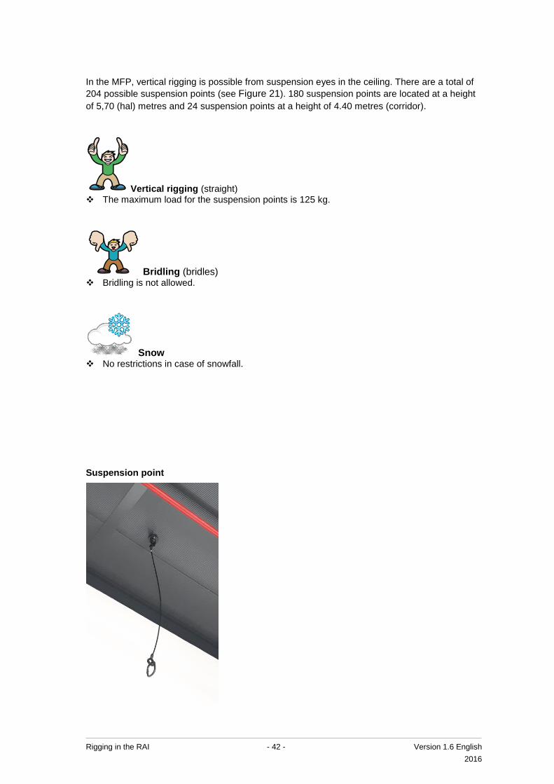
In the MFP, vertical rigging is possible from suspension eyes in the ceiling. There are a total of
204 possible suspension points (see Figure 21). 180 suspension points are located at a height
of 5,70 (hal) metres and 24 suspension points at a height of 4.40 metres (corridor).
Vertical rigging (straight) The maximum load for the suspension points is 125 kg.
Bridling (bridles) Bridling is not allowed.
Snow No restrictions in case of snowfall.
Suspension point

Rigging in the RAI - 43 - Version 1.6 English
2016
18 HALL 10
Figure 22: Rigging options in Hall 9
Height of suspension points
Height:
“Rigging
section”
RAI LIVE
Construction
(see appendix
II)
Note: This figure shows the
bottom part and the joints in the
upper part of the 3-dimensional
framework.

Rigging in the RAI - 44 - Version 1.6 English
2016
In Hall 10, rigging is allowed from the bottom part and the upper part of the 3-dimensional
framework. In order to make maximum use of Hall 9, it has been divided into 4 notional
“rigging sections” (see Figure 22). Each section area has a maximum suspension load of
22,500 kg. The weight is to be distributed as follows:
Table 12: Distribution of weight on the members 1 / 2 / 3 / 4 / 5 / 6
Total rigging load per
section up to 10,000 kg 10,000-22,500 kg
Vertical
(upper and lower part)
Max. 500 kg per member. Max. 500 kg per member.
Bridling
(upper or lower part)
Max. 500 kg per bridle and
max. 250 kg vertical load per
member.
Max. 400 kg per bridle and
max. 200 kg vertical load per
member.
Snowfall
(more than 5 cm)
Max. 160 kg per member.
Max. 250 kg per bridle and
max. 125 kg vertical load per
member.
More than 10,000 kg per area not
possible. See requirements under
10,000 kg.
1 A member forms part of the upper or lower part between two joints.
2 The maximum load may be distributed between one or more suspension points.
3 Suspension is not allowed around the lighting fixtures under the members (see CAD drawing).
4 If a member in the upper part and an adjacent member in the lower part are used at the same time, the
maximum permissible weight for these members will be halved.
5 If a member and an adjacent joint are loaded, the load on the member must be added to the load on the
joint. The total weight must never exceed the maximum load for the joint.
6 If the RAI LIVE screens are suspended in their construction, restrictions apply (see Appendix II).
Table 13: Distribution of weight on joints 1 / 2 / 3 / 4 / 5 / 6
Total rigging load per
section up to 10,000 kg 10,000-22,500 kg
Vertical
(upper and lower part)
Max. 900 kg per joint. Max. 900 kg per joint.
Bridling
(upper or lower part)
Max. 1,800 kg per bridle and
max. 900 kg vertical load per joint.
Max. 1,800 kg per bridle and
max. 900 kg vertical load per joint.
Snowfall
(more than 5 cm)
Max. 450 kg per joint.
Max. 900 kg per bridle and
max. 450 kg vertical load per joint.
More than 10,000 kg per area not
possible. See requirements under
10,000 kg.
1 The maximum load may be distributed between one or more suspension points per member.
2 If a joint in the upper part and an adjacent joint in the lower part are used at the same time, the
maximum permissible weight for these joints will be halved.
3 If a member and an adjacent joint are loaded, the load on the member must be added to the load on the
joint. The total weight must never exceed the maximum load for the joint.
4 There are rules which apply to suspension from the joints (see next page).
5 If the RAI LIVE screens are suspended in their construction, restrictions apply (see Appendix II).
6 Rigging is not permitted from the eyes under the joints.

Rigging in the RAI - 45 - Version 1.6 English
2016
Requirements for attachment to the roof construction:
Through the centre of the joint. Between lower
cross truss and cross diagonals.
Note:
For bridles, attach in the direction of the lifting
point.
Through the centre of the joint. Between lower
cross truss and cross diagonals.
Note:
Feed steel sling underneath existing cables

Rigging in the RAI - 46 - Version 1.6 English
2016
19 HALL 11
Figure 23: Rigging options in Hall 10
Height of suspension points
Height:
“Rigging
section”
RAI LIVE
Construction
(see appendix
II)
Note: This figure shows the
bottom part and the joints in the
upper part of the 3-dimensional
framework.

Rigging in the RAI - 47 - Version 1.6 English
2016
In Hall 11, rigging is allowed from the bottom part and the upper part of the 3-dimensional
framework. In order to make maximum use of Hall 10, it has been divided into 4 notional
“rigging sections” (see Figure 23). Each section area has a maximum suspension load of
22,500 kg. The weight is to be distributed as follows:
Table 14: Distribution of weight on the members 1 / 2 / 3 / 4 / 5 / 6
Total rigging load per
section up to 10,000 kg 10,000-22,500 kg
Vertical
(upper and lower part)
Max. 500 kg per member. Max. 500 kg per member.
Bridling
(upper or lower part)
Max. 500 kg per bridle and
max. 250 kg vertical load per
member.
Max. 400 kg per bridle and
max. 200 kg vertical load per
member.
Snowfall
(more than 5 cm)
Max. 160 kg per member.
Max. 250 kg per bridle and
max. 125 kg vertical load per
member.
More than 10,000 kg per area not
possible. See requirements under
10,000 kg.
1 A member forms part of the upper or lower part between two joints.
2 The maximum load may be distributed between one or more suspension points.
3 Suspension is not allowed around the lighting fixtures under the members (see CAD drawing).
4 If a member in the upper part and an adjacent member in the lower part are used at the same time, the
maximum permissible weight for these members will be halved.
5 If a member and an adjacent joint are loaded, the load on the member must be added to the load on the
joint. The total weight must never exceed the maximum load for the joint.
6 If the RAI LIVE screens are suspended in their construction, restrictions apply (see Appendix II).
Table 15: Distribution of weight on joints 1 / 2 / 3 / 4 / 5 / 6
Total rigging load per
section up to 10,000 kg 10,000-22,500 kg
Vertical
(upper and lower part)
Max. 900 kg per joint. Max. 900 kg per joint.
Bridling
(upper or lower part)
Max. 1,800 kg per bridle and
max. 900 kg vertical load per joint.
Max. 1,800 kg per bridle and
max. 900 kg vertical load per joint.
Snowfall
(more than 5 cm)
Max. 450 kg per joint.
Max. 900 kg per bridle and
max. 450 kg vertical load per joint.
More than 10,000 kg per area not
possible. See requirements under
10,000 kg.
1 The maximum load may be distributed between one or more suspension points per member.
2 If a joint in the upper part and an adjacent joint in the lower part are used at the same time, the
maximum permissible weight for these joints will be halved.
3 If a member and an adjacent joint are loaded, the load on the member must be added to the load on
the joint. The total weight must never exceed the maximum load for the joint.
4 There are rules which apply to suspension from the joints (see next page).
5 If the RAI LIVE screens are suspended in their construction, restrictions apply (see Appendix II).
6 Rigging is not permitted from the eyes under the joints.

Rigging in the RAI - 48 - Version 1.6 English
2016
Requirements for attachment to the roof construction:
Through the centre of the joint. Between lower
cross truss and cross diagonals.
Note:
For bridles, attach in the direction of the lifting
point.
Through the centre of the joint. Between lower
cross truss and cross diagonals.
Note:
Feed steel sling underneath existing cables

Rigging in the RAI - 49 - Version 1.6 English
2016
20 HALL 12
Figure 24: Rigging options in Hall 12
“Rigging
section”
RAI LIVE
Construction
(see appendix
II)
Note: This figure shows the
bottom part and the joints in the
upper part of the 3-dimensional
framework.
Height of suspension points
Height:

Rigging in the RAI - 50 - Version 1.6 English
2016
In Hall 12 rigging is allowed from the bottom part and the upper part of the 3-dimensional
framework. In order to make maximum use of Hall 12, it has been divided into 4 notional
“rigging sections” (see Figure 24). Each section area has a maximum suspension load of
22,500 kg. The weight is to be distributed as follows:
Table 16: Distribution of weight on the members 1 / 2 / 3 / 4 / 5 / 6
Total rigging load per
section up to 22,500 kg 22,500-50,000 kg
Vertical
(upper and lower part)
Max. 500 kg per member. Max. 500 kg per member.
Bridling
(upper or lower part)
Max. 500 kg per bridle and
max. 250 kg vertical load per
member.
Max. 400 kg per bridle and
max. 200 kg vertical load per
member.
Snowfall
(more than 5 cm)
Max. 160 kg per member.
Max. 250 kg per bridle and
max. 125 kg vertical load per
member.
More than 10,000 kg per area not
possible. See requirements under
10,000 kg.
1 A member forms part of the upper or lower part between two joints.
2 The maximum load may be distributed between one or more suspension points.
3 Suspension is not allowed around the lighting fixtures under the members (see CAD drawing).
4 If a member in the upper part and an adjacent member in the lower part are used at the same time, the
maximum permissible weight for these members will be halved.
5 If a member and an adjacent joint are loaded, the load on the member must be added to the load on the
joint. The total weight must never exceed the maximum load for the joint.
6 If the RAI LIVE screens are suspended in their construction, restrictions apply (see Appendix II).
Table 17: Distribution of weight on joints 1 / 2 / 3 / 4 / 5 / 6
Total rigging load per
section up to 22,500 kg 22,500-50,000 kg
Vertical
(upper and lower part)
Max. 900 kg per joint. Max. 900 kg per joint.
Bridling
(upper or lower part)
Max. 1,800 kg per bridle and
max. 900 kg vertical load per joint.
Max. 1,800 kg per bridle and
max. 900 kg vertical load per joint.
Snowfall
(more than 5 cm)
Max. 450 kg per joint.
Max. 900 kg per bridle and
max. 450 kg vertical load per joint.
More than 10,000 kg per area not
possible. See requirements under
10,000 kg.
1 The maximum load may be distributed between one or more suspension points per member.
2 If a joint in the upper part and an adjacent joint in the lower part are used at the same time, the
maximum permissible weight for these joints will be halved.
3 If a member and an adjacent joint are loaded, the load on the member must be added to the load on the
joint. The total weight must never exceed the maximum load for the joint.
4 There are rules which apply to suspension from the joints (see next page).
5 If the RAI LIVE screens are suspended in their construction, restrictions apply (see Appendix II).
6 Rigging is not permitted from the eyes under the joints.

Rigging in the RAI - 51 - Version 1.6 English
2016
Requirements for attachment to the roof construction:
Through the centre of the joint. Between lower
cross truss and cross diagonals.
Note: For bridles, attach in the direction of the
lifting point.
Through the centre of the joint. Between lower
cross truss and cross diagonals.
Note: Feed steel sling underneath existing
cables

Rigging in the RAI - 52 - Version 1.6 English
2016
21 HALL 13
Figure 25: Suspension points in the Elicium Ballroom
Distance between suspension points
Distance between red suspension points at
height of 6,80
: 5,78 m
: 4,73 m
Distance between blue suspension points at
height of 8,70
:11,56m
: 2,40 m en 7,06 m
Height of suspension points
Height red: 6,80 m
Height green: 6,80 m
Height blue: 8,70 m
Rails
The thick lines indicate rails.
Suspension points can be created
at the locations shown along
these rails using specially
designed hoisting elements,
provided that there is no partition
wall fitted to the rails.

Rigging in the RAI - 53 - Version 1.6 English
2016
In the Elicium Ballroom, vertical rigging is possible from suspension eyes in the ceiling. There
are a total of 92 possible suspension points. 62 suspension points are located at a height of 6.80
metres (see red dots in Figure 25) and 30 suspension points at a height of 8.70 metres (see
blue dots in Figure 25).
Note: Rails are installed in the roof (see Figure 25). Specially designed suspension eyes can be
fitted at the locations indicated (green dots), provided that there is no partition wall fitted to the
rails. These suspension eyes are to be requested via the Account Manager of the RAI.
Vertical rigging (straight) The maximum load for the 25 “red” suspension points is 125 kg. The maximum load for the 37 “green” suspension points is 125 kg. The following applies to the 30 “blue” suspension points:
o If one of the suspension eyes from a pair adjacent to each other is loaded, the maximum load is 125 kg.
o If both of the suspension eyes from a pair adjacent to each other are loaded, the maximum load is 62.5 kg.
Bridling (bridles) Bridling is not allowed.
Snow No restrictions in case of snowfall.

Rigging in the RAI - 54 - Version 1.6 English
2016
Requirements for attachment to the roof construction:
“Green suspension points”
Note: The rail eyes must be positioned
on the rail at right angles.
“Red suspension points”
“Blue suspension points”

Rigging in the RAI - 55 - Version 1.6 English
2016
Height of suspension points
Height: 3,74 m
Between the suspension points
: 7,50 m
: 3,75 m
22 AUDITORIUM LOUNGE AND ONYX LOUNGE
Figure 26: Auditorium Lounge and Onyx Lounge suspension points

Rigging in the RAI - 56 - Version 1.6 English
2016
In the Auditorium Lounge and Onyx Lounge vertical rigging is permitted from eyes in the
ceiling. There are a total of 34 possible suspension points (see Figure 26).
Vertical rigging (straight) Vertical rigging is allowed from eyes in the ceiling. The maximum load per eye is 150 kg.
Bridling (bridles) Bridling is not allowed.
Snow No restrictions in case of snowfall.
Requirements for attachment to the roof construction:
Note:
Before carrying out rigging, (CE and WLL)
certified eye bolts must be fitted. The thread of
the eye bolts is M12.

Rigging in the RAI - 57 - Version 1.6 English
2016
23 UPPER LOUNGE AND EMERALD LOUNGE
Figure 27: Upper Lounge and Emerald Lounge suspension points
Height of suspension points
Height: 3,74 m
Between the suspension points
: 7,50 m
: 3,75 m

Rigging in the RAI - 58 - Version 1.6 English
2016
In the Upper Lounge and Emerald Lounge vertical rigging is allowed from eyes in the
ceiling. There are a total of 16 possible suspension points (see Figure 27).
Vertical rigging (straight) Vertical rigging is allowed from eyes in the ceiling. The maximum load per eye is 150 kg.
Bridling (bridles) Bridling is not allowed.
Snow No restrictions in case of snowfall.
Requirements for attachment to the roof construction:
Note:
Before carrying out rigging, (CE and WLL)
certified eye bolts must be fitted. The thread of
the eye bolts is M12.

Rigging in the RAI - 59 - Version 1.6 English
2016
24 DIAMOND LOUNGE
Figure 28: Suspension points in the Diamond Lounge
Height of suspension
points
Height: 3.50 m

Rigging in the RAI - 60 - Version 1.6 English
2016
In the Diamond Lounge, vertical rigging is allowed from eyes in the ceiling. There are a total of
24 suspension points in the Diamond Lounge (see Figure 28).
Vertical rigging (straight) Vertical rigging is allowed from eyes in the ceiling. The maximum load per eye is 150 kg.
Bridling (bridles) Bridling is not allowed.
Snow Not applicable.
Requirements for attachment to the roof construction:
Note:
Before carrying out rigging, (CE and WLL)
certified eye bolts must be fitted. The thread of
the eye bolts is M12.

Rigging in the RAI - 61 - Version 1.6 English
2016
25 EUROPE FOYER 1 AND 2
Figure 29: Rigging options in Europe Foyer 1 and 2
Height of suspension
points
Height: 3.10 m
Suspension point

Rigging in the RAI - 62 - Version 1.6 English
2016
In Europe Foyer 1 and 2 vertical rigging is allowed from eyes in the ceiling. There are a total of
96 possible suspension points (see Figure 29). The fitting of own lifting eyes is not permitted.
Vertical rigging (straight) Vertical rigging is allowed from the eyes in the ceiling. The maximum load per eye is 125 kg.
Bridling (bridles) Bridling is not allowed.
Snow No restrictions in case of snowfall.

Rigging in the RAI - 63 - Version 1.6 English
2016
26 ROOM G102
Figure 30: Suspension points in G102
Note:
The maximum permissible load
is 150 kg per point and
the maximum permissible load
per cluster is 150 kg.

Rigging in the RAI - 64 - Version 1.6 English
2016
In Room G102 there are 21 suspension points (see Figure 30). The suspension points are
to be used as follows:
Vertical rigging (straight) Vertical rigging is allowed from eyes in the ceiling. The maximum load per eye is 150 kg. The maximum load per cluster is 150 kg, to be distributed between the suspension points in
the cluster.
Bridling (bridles) Bridling is not allowed.
Snow No restrictions in case of snowfall.
Requirements for attachment to the roof construction:
Note:
Before carrying out rigging, (CE and WLL)
certified eye bolts must be fitted. The thread of
the eye bolts is M12.

Rigging in the RAI - 65 - Version 1.6 English
2016
APPENDIX I: REQUIREMENTS FOR THE RIGGING PLAN
The table below shows the format for the rigging plan to be submitted to the RAI. Send the
rigging plan to the Accountmanager at the RAI Amsterdam. Incomplete rigging plans will not be
assessed and therefore will not be approved. The RAI can provide an example of an acceptable
rigging plan on request.
Section of rigging plan Requirements per section By whom
1. Lifting point plan
(submit as dwg plus
copy as pdf)
Entered on CAD drawing from the RAI
Amsterdam1: a. The objects to be lifted. b. Lifting equipment (trusses, auxiliary
trusses, hoists and suchlike). c. The locations of the lifting points with
reference number (corresponding to Excel sheet points 2, 3 and 4).
d. F vertical per lifting point. e. F vertical per application locations of the
bridles.
Responsible
rigging
company
2. Calculated weight of
the loads
(submit as Excel sheet)
Entered in the RAI Amsterdam rigging
calculations format a. Reference number per lifting point; b. Product name, type and weight of all
objects that belong to the hoisted load (incl. hoisting elements);
c. Total weight per lifting point/application location
Responsible
rigging
company
3. Calculation of
weight of bridles loads
(submit as Excel sheet)
Entered in the RAI Amsterdam rigging
calculations format a. Reference number per lifting point b. Product name, type and weight of all
objects that belong to the hoisted load (incl. hoisting elements);
c. Calculated vertical forces on the lifting points/application locations.
d. The bridle angle
Responsible
rigging
company
3. Total weight of
several suspension
points on a truss part
(submit as Excel sheet)
Entered in the RAI Amsterdam rigging
calculations format a. If a number of forces apply at a point on
the truss / suspension point, the sum of the weights of these points must be shown in the final column of the Excel sheet
Responsible
rigging
company
1. Each part of the building from this rigging manual has its own CAD drawing on which
the possible suspension points are indicated.

Rigging in the RAI - 66 - Version 1.6 English
2016
APPENDIX II: RAI LIVE RESTRICTIONS HALLS 8, 10, 11 AND 12
In Halls 8, 10, 11 and 12 there is a suspended construction to
which RAI LIVE information screens can be attached. If the
screens are suspended in the construction, the following rigging
restrictions apply:
In the area marked by the green lines in Figure 31, the maximum
permissible weights for Halls 8, 10 11 and 12 must be halved.
Note: No restrictions apply if the screens are not suspended in the
construction and the trolley beam is located between four
suspension points (this location is indicated with a black arrow).
Figure 31: Area with rigging restriction around RAI LIVE construction