rights / license: research collection in copyright - non ...26475/... · diss. ethnr. 15025...
TRANSCRIPT
Research Collection
Doctoral Thesis
Development of ultrahigh strength austenitic stainless steelsalloyed with nitrogen
Author(s): Cobelli, Paolo
Publication Date: 2003
Permanent Link: https://doi.org/10.3929/ethz-a-004550660
Rights / License: In Copyright - Non-Commercial Use Permitted
This page was generated automatically upon download from the ETH Zurich Research Collection. For moreinformation please consult the Terms of use.
ETH Library
Diss. ETH Nr. 15025
DEVELOPMENT OF ULTRAHIGH STRENGTH AUSTENITIC
STAINLESS STEELS ALLOYED WITH NITROGEN
A dissertation submitted to the
SWISS FEDERAL INSTITUTE OF TECHNOLOGY
In ZURICH
For the degree of Doctor of Technical Sciences
presented by
PAOLO COBELLI
Dipl. Mechanical Eng. BRESCIA (I)born on December 25th, 1968
in ITALY, Italian
accepted on recommendation of
prof. Dr. Dr. h.c. Markus O. Speidel, examiner
prof. Dr. Peter J. Uggowitzer, co-examiner
prof. Dr. Sannakaisa Virtanen, co-examiner
2003
ACKNOWLEDGMENTS
This research project was carried out from January 2000 to January 2003 at the Institute of
Metallurgy of ETH - Swiss Federal Institute of Technology in Zürich, Switzerland.
I am very much indebted to my supervisor and head of the Institute Prof. Dr. Dr. h.c.
Markus O. Speidel for his encouragement, constructive suggestions and guidance throughout
the course ofthis work.
Special thanks to Prof. Dr. Sannakaisa Virtanen and Prof. Dr. Peter J. Uggowitzer ("Uggo")
for being my co-examiners and Prof. Dr. Nie Spencer to preside over my Ph.D. examination.
I would also like to express my sincere thanks to all my colleagues and friends met at the
Institute of metallurgy for their technical and personal help, in particular:Dr. Ruth M. Magdowski, Dr. Markus Diener ("Dinero"), Dr. Christian Solenthaler (our TEM
specialist; I will never forget his „theoretical talent" and our beautiful discussions about S.
Hawking and "black holes"), Mr. Eduard Schaller ("Edi" who helped me during
metallographic investigations), Mrs. Ming Ling Zheng (wo de hanyu lao shi, wo de hen hao
zhongguo ren pongyou, tai xiexie ni le), Mrs. Gisela Angst ("Gisi" who made some of the
Figures in chapter 7 and helped me to solve any bureaucratic problems during my staying in
Switzerland), Dr. Hannes Speidel and Dr. Young Hwan Kim from POSCO South-Korea (both
of them are my best friends), all the "crazy guys" of the "Werkstatt''', in particular Mr. Markus
Müller ("Bio", who helped me in the melting shop and during my first year here in Zurich)
and Mr. Nikiaus Koch ("Claus" - drei Jahre lange zeit © ), Mr. Guido Savazzi ("il mantovano
verace") and Mr. C. Wegmann ("Wegi" with his famous sentence: "if you have any problems
ask to me").
1 would also like to thank some "old date" friends:
Prof. Roberto Roberti (head of the Department of Mechanical Engineering at Brescia
University - Italy, my starting point), Prof. G.M. La Vecchia (Brescia), Dr. Marco Comini
(Udine), Mr. Pierivano Cherubini ("Cherubba" Brescia) and Mr. G. Sciamanna ("GiPi" who
taught me the secrets of the "Schmeltzhalle"...,now happily retired in Ravenna, Italy).
Finally, many thanks to my sister (Gabriella) and brother (Roberto), and their family, who
take care of my old mother "Gina" in Italy during my staying abroad; they always
encouraged and supported me to continue with my studies.
A deep and special though also in memory of my father, Mr. Mario Cobelli, passed away
when I was still young.
Above all I owe an extra special thank to my girlfriend Ms. Payorm Srichumpa, for her love
and understanding during these years of "Doktorat"; without her support and encouragements
this thesis work would have been impossible.
2
ABSTRACT
It is well established that nitrogen in austenitic stainless steels causes a remarkable high
strengthening by solid solution as well as an increasing in corrosion resistance.
For these reasons nitrogen as an alloying element has been successfully used to develop a
number of commercial steels in which it stabilizes the austenitic phase (High Nitrogen
Austenitic stainless Steels -HNASS).
Presently these steels are manufactured by ingot metallurgy carried out under high nitrogen
partial pressure in order to achieve sufficient high nitrogen solubility, or by powder
metallurgy. Both production routes are "expensive" and quite "exotic", and this explains why
in spite of a good knowledge on favourable effects by nitrogen alloying in austenitic stainless
steels, high nitrogen austenitic stainless steels have not been extensively used and adopted in
large quantities yet.This thesis describes the development of new Ultrahigh Strength High Nitrogen Austenitic
Stainless Steels with very low nickel content, designed to be made by "ingot metallurgy
without overpressure", i.e. using conventional steel making facilities.
These new steels are interesting candidates for structural application in car industry, building
industry and ocean engineering, due to high mechanical strength, high resistance to corrosion
and low cost of production.
By means of laboratory experiments combined with thermodynamic calculations suitable
alloy compositions were designed in order to increase the nitrogen solubility at atmospheric
pressure in the liquid and solid phase, avoiding porosity formation into cast ingots during
solidification.
On these new alloys the effect of:
solid solution hardening;
grain boundary hardening;dislocation hardening (during cold working);dislocation hardening (during hot working);
precipitation hardening (strain ageing);
on yield strength, ultimate tensile strength and elongation to fracture were investigated in a
systematic way.
A high level of strength was achieved combining different strengthening mechanisms
following the rule: nitrogen in solid solution as high as possible, grain size as small as
possible and cold deformation as high as possible.Solid solution hardening was optimised choosing "the right" amount of carbon and nitrogen
taking in account that high nitrogen austenitic stainless steel undergoes to a ductile to brittle
transition at room temperature as the sum of nitrogen and carbon content in solid solution
approaches one weight percent.The dependence of the ductile to brittle transition upon alloying elements and grain size was
explored.The introduction of strong nitride former elements, mainly vanadium and niobium, able to
form nitrides more stable than those based on chromium and molybdenum, was investigated
in order to achieve small grains in bulk materials.
The role of nitrogen on dynamic recrystallization and dislocation hardening during hot rolling
was investigated. Nitrogen in solid solution was found to have profound influence on the
temperature of dynamic recrystallization and hence on the thermo-mechanical processes such
as hot rolling, where an improved hot workability of the austenite becomes the first target to
achieved.
3

RIASSUNTO
L'aggiunta di azoto in acciai inossidabili austenitici provoca uno straordinario aumento della
resistenza meccanica, grazie al notevole rafforzamento per soluzione solida, e della resistenza
alia corrosione.
Per queste ragioni sempre piu spesso nella produzione dei moderni acciai inossidabili
austenitici viene impiegato azoto.
Recentemente è stata sviluppata anche una nuove classe di acciai in cui l'azoto agisce
principalmente come elemento austenitizzante, consentendo una riduzione del tenore di nickel
(Acciai Inossidabili Austenitici all'Azoto: High Nitrogen Austenitic Stainless Steels).
Attualmente questi acciai sono prodotti per mezzo della metallurgia fusoria del lingotto
conducendo la fusione in presenza di una elevata pressione parziale di azoto o per mezzo dei
metodi della metallurgia delle polveri. Tali vie di produzione sono piuttosto costose,
richiedendo equipaggiamenti particolari e complessi; questo è un motivo per il quale gli acciai
ad alto tenore di azoto non hanno ancora trovato ampie applicazioni, a dispetto di una buona
conoscenza degli effetti favorevoli che l'alligazione con azoto comporta in una matrice
austenitica.
Questa Tesi di Dottorato vuole descrivere lo sviluppo di nuovi acciai inossidabili austenitici
ad alto tenore di azoto dotati di una elevata resistenza meccanica, contenenti poco nickel,
progettati per essere prodotti ricorrendo alia metallurgia fusoria del lingotto senza bisogno di
sovrapressione, usando cioè equipaggiamenti fusori tradizionali.
Questi nuovi acciai sono potenziali candidati per applicazioni strutturali nell'ambito
dell'industria automobilistica, delle costruzioni civili e marine, per via della loro elevata
resistenza meccanica, elevata resistenza alia corrosione e basso costo di produzione.Per mezzo di esperimenti condotti in laboratorio affiancati da simulazioni termodinamiche al
calcolatore, sono state sviluppate composizioni chimiche capaci di aumentare la solubilità
dell'azoto a pressione atmosferica sia in fase liquida che solida; acciai austenitici con elevato
tenore di azoto sono stati cosi ottenuti senza formazione di porosità nei longotti durante la
fase di solidificazione.
Con queste nuove leghe è stato successivamente valutato l'effetto dell'azoto sui meccanismi
di rafforzamento:
• per soluzione solida;
• per affinamento del grano;
• per incrudimento (durante lavorazioni plastiche a freddo e a caldo);
• per precipitazione ed invecchiamento.
L'effetto di questi meccanismi di rafforzamento è stato valutato in termini delle seguenti
propietà dell'acciaio: resistenza alio snervamento, sforzo a rottura, duttilità e tenacità.
Una resistenza meccanica estremamente elevata è stata ottenuta combinando differenti
meccanismi di rafforzamento seguendo la seguente strategia: tenore di azoto in soluzione
solida piu elevato possible, dimensioni dei grani piu piccole possibili e incrudimento piu
elevato possible.II rafforzamento per soluzione solida è stato ottimizzato scegliendo la quantita "giusta" di
azoto e carbonio tenendo présente che gli acciai inossidabili austenitici ad alto tenore di azoto
vanno soggetti al fenomeno della transizione dutile-fragile a temperatura ambiente quando la
somma tra il tenore di carbonio e di azoto raggiunge la soglia dell'un per cento.
La dipendenza della temperatura a cui si manifesta la transizione duttile-fragile da altri fattori,
quali il tenore degli altri elementi di lega e la dimensione del grano, è stata anche investigata.
4

L'introduzione di elementi affinanti, principalmente vanadio e niobio, in grado di formare
nitruri piu stabili di quelli basati sul cromo e molibdeno, e' stata investigata allô scopo di
ottenere un affinamento del grano austenitico in pezzi di notevoli dimensioni.
L'influenza dell'azoto sul fenomeno della ricristallizazione dinamica e "incrudimento" che ha
luogo durante la laminazione a caldo è stato investigate L'azoto in soluzione solida ha una
profonda influenza sulla temperatura di ricristallizazione dinamica e quindi sui processitermomeccanici corne la laminazione a caldo, per la quale la lavorabilità a caldo
dell'austenite diventa un paramétra importante.
5
INDEX
1. INTRODUCTION 9
1.1 STAINLESS STEELS 9
1.2 AUSTENITIC STAINLESS STEELS 9
1.3 HIGHNITROGEN AUSTENITIC STAINLESS STEELS 11
2. PROPERTIES OF HIGH NITROGEN AUSTENITIC STAINLESS STEELS 12
2.2 AUSTENITE STABILITY 12
2.3 MECHANICAL PROPERTIES 15
2.4 CORROSION RESISTANCE 17
3. THEORETICAL ASPECTS OF HIGH NITROGEN AUSTENITIC STAINLESS STEELS 22
3.1 NITROGEN IN SOLID SOLUTION 22
3.2 NITROGEN AND PLASTIC DEFORMATION 24
3.3 NITROGEN AND GRAIN BOUNDARIES 25
3.4 STRAIN AGEING HARDENING 27
3.5 TOUGHNESS AND DUCTILE TO BRITTLE TRANSITION (DBTT) 28
3.6 CHEMICAL PROPERTIES 31
4. PRODUCTION ROUTES OF HIGH NITROGEN STAINLESS STEELS 33
5. AIM OF THE PROJECT 37
6. HIGH NITROGEN AUSTENITIC STAINLESS STEELS MICROALLOYED WITH
NIBIUM AND VANADIUM 38
6.1 SCOPE 38
6.2 MATERIALS AND METHODS 38
6.3 RESULTS 39
6.3.1 NITROGEN AND CARBON IN SOLID SOLUTION 39
6.3.1.1 TOUGHNESS 39
6.3.1.2 YIELD STRENGTH AND ULTIMATE TENSILE STRENGTH 43
6.3.1.3 DUCTILE TO BRITTLE TRANSITION 43
6.3.2 GRAIN REFINING BY NIOBIUM 45
6.3.2.1 TOUGHNESS 45
6.3.2.2 YIELD STRENGTH AND ULTIMATE TENSILE STRENGTH 49
6.3.2.3 DUCTILE TO BRITTLE TRANSITION 51
6.3.3 GRAIN REFINING BY VANADIUM 52
6.3.3.1 TOUGHNESS 52
6.3.3.2 YIELD STRENGTH AND ULTIMATE TENSILE STRENGTH 53
6.3.3.3 DUCTILE TO BRITTLE TRANSITION 56
6.3.4 GRAIN REFINING BY VANADIUM PLUS NIOBIUM 56
6.3.4.1 TOUGHNESS 56
6.3.4.2 YIELD STRENGTH AND ULTIMATE TENSILE STRENGTH 57
6

6.4 DISCUSSION 58
7. STRENGTHENING MECHANISMS IN HIGH NITROGEN AUSTENITIC
STAINLESS STEELS 59
7.1 SCOPE 59
7.2 MATERIALS AND METHODS 59
7.3 RESULTS 61
7.3.1 GRAIN BOUNDARY HARDENING 61
7.3.1.1 STATIC RECRYSTALLIZATION EXPERIMENTS (SRX) 61
7.3.1.2 EFFECT OF NITROGEN 63
7.3.2 DISLOCATION HARDENING AND PRECIPITATION HARDENING 70
7.3.3 STRENGTH AND DUCTILITY COMBINED 74
7.3.4 DUCTILE TO BRITTLE TRANSITION IN HNS 76
7.4 DISCUSSION 85
8. HOT ROLLING OF HIGH NITROGEN AUSTENITIC STAINLESS STEELS 86
8.1 SCOPE 86
8.2 HOT ROLLING AND DYNAMIC RECRYSTALLIZATION (DRX) 86
8.3 MATERIALS AND METHODS 89
8.4 RESULTS 91
8.4.1 EFFECT PF DIFFERENT QUENCHING ROUTES AFTER HOT ROLLING 91
8.4.1.1 HARDNESS MESSUREMENTS 91
8.4.1.2 TENSILE PROPERTIES AND TOUGHNESS 92
8.4.2 MECHANICAL PROPERTIES OF ALLOYS HOT ROLLED AND SRX 96
8.4.3 ALLOYS PROPERLY DEVELOPED FOR HOT ROLLING 101
8.5 DISCUSSION 104
9. APPLICATIONS OF HIGH NITROGEN AUSTENITIC STAINLESS STEELS 105
10. OUTLOOK 106
APPENDIX 1 : DECOMPOSITION OF AUSTENITE IN AUSTENITIC STAINLESS STEELS 107
A.l INTERMETALLIC PHASES 107
A. 1.1 SIGMA PHASE 108
A. 1.2 CHIPHASE 109
A. 1.3 LAVES PHASES 109
A.2 CARBIDES PRECIPITATION 109
A.2.1 M23C6 CARBIDES 110
A.2.2 MC CARBIDES 110
A.2.3 M6C CARBIDES 110
A.3 NITRIDES 111
A.3.1 PRIMARY NITRIDES MN 111
A.3.2 SECONDARY NITRIDES M2N 111
7

APPENDIX 2: INTERACTION PARAMETERS ACCORDING ZHENG 112
APPENDIX 3: ALLOYS' PRODUCTION AND PROCESSING ROUTES 113
APPENDIX 4: ALLOYS CHEMICAL COMPOSITION 115
APPENDIX 5: EMPIRICAL MODEL FOR NITROGEN SOLUBILITY IN THE SYSTEM
Fe-Cr-Mn-Ni-Mo-C-N WITHOUT OVERPRESSURE 117
APPENDIX 6: EMPIRICAL CORRELATION BETWEEN HARDNESS HV10 AND YIELD
STRENGTH Rp02 IN HIGH NITROGEN AUSTENITIC STAINLESS
STEELS 118
REFERENCES 119
CURRICULUM VITAE 123
8
1. INTRODUCTION
1.1 STAINLESS STEELS
Stainless steels were invented at the beginning of the last century in Germany (Strauss and
Maurer 1912) and in England (Brearly 1913) as a surprise result of investigations about the
influence of chromium on steels.
Brearly's new alloy contained about 13wt% chromium and 0.25wt% carbon. It had a
martensitic structure and was used to manufacture cutlery.The work of Strauss and Maurer culminated in the development ofthe first austenitic stainless
steel, a precursor of 18/8 Cr-Ni steel (AISI 304).
Since that time the development in the field of corrosion resistant iron based materials has
been extensive. Stainless steels have been developed and investigated with a wide variety of
chemical compositions and processing techniques resulting in a wide range of properties (e.g.
tensile strengths range from 200 MPa up to 2000 MPa). Although a great array of property
combinations have been achieved, the single most important characteristic of all stainless
steel remains their corrosion resistance.
Today the only common characteristic of all stainless steels is a chromium content above 10
weight percent, necessary to prevent rust formation when exposed in air (hence the
designation stainless) through the formation of an invisible and adherent chromium rich oxide
surface film.
Beyond these restrictions many alloy combinations are possible; depending upon their
microstructure, stainless steels can be divided into four groups:
• martensitic
• austenitic
• ferritic
• duplex
1.2 AUSTENITIC STAINLESS STEELS
Austenitic stainless steels contain several alloying elements combined with an iron base to
achieve the desired microstructure and properties.The first austenitic stainless steels used nickel and carbon to stabilise the austenitic structure
[stral4, stra20] with 0.25-weight percent carbon for the one stage steel making practice used
at that time (melting, metal refining, reducing and alloying were done in the same crucible).
High carbon contents in early austenite steels caused problems during service; in these CrNi-
type steels, a short exposure in the temperature range 500 to 900°C results in Q23C6
precipitation along the grain boundaries, leading to material embrittlement and reduced
corrosion resistance because of chromium depletion in the matrix surrounding carbides. The
high affinity of carbon to chromium made these new steels susceptible to intergranular
corrosion.
It was only through the introduction of new steel making methods in the 1960s, Vacuum
Oxygen Decarburisation (VOD process) and Argon Oxygen Decarburisation (AOD process),
that carbon content was drastically reduced to avoid chromium rich carbides precipitation; in
9

the meanwhile other elements, such as nickel, manganese and nitrogen were used to stabilize
the austenite.
Today the majority of the commercial austenitic stainless steels have carbon content as low as
0.005 to 0.015 weight percent and are produced by AOD (for economic reasons), even though
VOD production allows higher quality steel.
Some well-known examples are the austenitic grades: AISI 304 and 316, their extra-low
carbon version 304L and 316L and their nitrogen alloyed version 304LN and 316LN.
Other elements, such as Mo, V, Ti and Nb may be added to enhance specific properties for
certain applications.
Tab. 1-1 summarises the principal elements found in modern stainless steels and their
respective influence on steel properties.
Element Dominant influence on the Material
Chromium ferritising corrosion resistance
Manganese austenitising / ferritising increases the nitrogen solubility
Nickel austenitising suppresses the formation of some
intermetallic phases
Molybdenum ferritising corrosion resistance
Copper ferritising corrosion resistance
Vanadium ferritising forms stable nitrides and carbides
(fee)
Niobium ferritising forms stable nitrides and carbides
Nitrogen austenitising increases strengthcorrosion resistance
Carbon austenitising increases strength
Titanium ferritising forms stable nitrides and carbides
Tab.1-1: alloying element of modern austenitic steels.
Unlike any other class of steels, austenitic stainless steels are used over a wide range of
service conditions, varying in temperature from -196°C to above 800°C, and in a wide range
of corrosive media. In addition to these severe operating conditions, stainless steels are
expected to be readily weldable and are required to maintain their strength and corrosion
resistance in the welded condition. Further, certain applications call for a high degree of cold
formability, hot forming and adequate machinability. The demands that are imposed on
stainless steels are therefore wide ranging and the versatility of this class of material is
particularly outstanding.Austenitic stainless steels are characterized by rather low yield strengths of the order of
200^-300 MPa in annealed condition at room temperature, with excellent ductility and
toughness.
Aiming to further improve the strength and corrosion resistance of austenitic stainless steels,
alternative alloy compositions and production technologies were investigated. The traditional
metallurgical strengthening mechanism (solid solution hardening, grain boundary hardening,
dislocation hardening, precipitation hardening and strain ageing) were applied and adapted.
Among all these researches, nitrogen was found to improve both mechanical strength and
corrosion resistance in an outstanding way.
10

1.3 HIGH NITROGEN AUSTENITIC STAINLESS TEELS
Nitrogen may exist in three forms in steels:
a. as gas molecule;
b. in interstitial solid solution;
c. precipitated as nitrides.
While gas pores are deleterious in steels as well as some nitrides, nitrogen in solid solution is
beneficial for austenitic stainless steels and it causes extraordinary improvements in corrosion
resistance and mechanical properties resulting in an unusual combination of strength and
fracture toughness.The first reports about nitrogen alloying at atmospheric pressure were published long ago, in
the 1938 by A.M.Samarin in the ex-URSS [Sama38] and F.Rapatz [Rapa41] and R.Scherer
[Scher42] in Germany, during investigations related to replace a certain amount of nickel in
the chromium-nickel stainless steels by manganese and nitrogen.Later during the nickel shortage period (50s) alloys with nickel contents as low as lwt%,
manganese contents from 4 to 17wt% and nitrogen contents up to 0.25wt% were developed,
culminating in alloy series AISI 200.
Although it was soon realized that nitrogen alloying has a strong influence on mechanical and
chemical properties of austenitic stainless steels, it was not possible to get the best
performances because of the low nitrogen solubility in the system Fe-Cr-Ni at atmosphericcondition. Only recently has been possible to increase the nitrogen solubility in steels beyondthe limit at atmospheric pressure, when different manufacturing routes (metallurgy under
pressure, centrifugal casting, powder metallurgy) were developed in different countries in
order to increase the nitrogen solubility [Feich91].It is in this framework that high nitrogen stainless steels (HNS) were invented.
Even if the original definition of "high nitrogen steels" was reserved to steels produced under
gas pressure (pressure metallurgy), today a steel to be considered "high nitrogen" has to
contain a minimum of 0.08wt% nitrogen in solid solution with a ferritic matrix and a
minimum of 0.4wt% nitrogen with an austenitic matrix [Speid90].HNS have been developed to such extent that this group of steels now includes the materials
which exhibit the highest combination of strength and fracture toughness among all the
structural materials [Speid87].The origins of these outstanding results were found in the peculiar interactions between
nitrogen and lattice defects and atoms of other alloying elements, different from the ones
expected from the more traditional interstitial element like carbon. For these reasons high
nitrogen steels are principally new materials.
11
2. PROPERTIES OF HIGH NITROGEN AUSTENITIC
STAINLESS STEELS
High nitrogen austenitic stainless steels combine a large number of advantages over the
traditional low nitrogen or nitrogen free austenitic stainless steels.
These advantages include:
• nitrogen as a potential low cost alloying element;
• nitrogen as an austenite stabilizer;
• nitrogen as a solid solution hardening element;
• nitrogen improving fine grain hardening;• nitrogen improving the coefficient ofwork hardening;
• nitrogen improving the pitting corrosion resistance;
• nitrogen improving the crevice corrosion resistance;
• nitrogen improving the intergranular corrosion;
• nitrogen as an essential element for the development of high strength, stress
corrosion cracking resistant stainless steels.
It is the combination of these advantages, which constitutes the basis of the industrial
applicability ofhigh nitrogen austenitic stainless steels.
2.1 AUSTENITE STABILITY
In order to achieve the above mentioned advantages a fully austenitic microstructure is
requested, hence it is of prime importance to know the metallurgical limits of the austenite
single phase region in the multicomponent alloys.The modified Schaeffler diagram introduced by Speidel and Uggowitzer for high chromium
steels [Speid87], describes the influence of predominant alloying elements on microstructure
dividing them into two groups:
austenite promoter elements their effects are described in terms of the Ni equivalent:
Nieqv = Ni + Co + O.IMn - O.OIMn2 + 18N + 30C [1]
ferrite promoter elements their effects are described in terms of the Cr equivalent:
Creqv = Cr + 1.5Mo + 1.5W + 0.48Si + 2.3V + 1.75Nb + 2.5A1 [2]
The diagram in Fig, 2-1 shows that austenitic steels need a minimum Nieqv of about 10, this
gives a metallurgical limit for austenitic iron based materials.
Formula [1] shows the very powerful austenite stabilizer effect ofnitrogen:1 weight percent of nitrogen in solid solution is as effective as 18 weight percent nickel!
Therefore nitrogen can replace the more expensive alloying element nickel in order to
stabilize the austenite giving the possibility to develop a new class of Ni-free austenitic
12

stainless steels [Uggo96], as well as duplex Ni-free stainless steels [Wang98], cheaper than
the traditional ones with nickel.
OoCO+
z00
o
o
c
o+o
Ü+
>CTa
40
35
30
25
20
15
10
5
0
austenite
-
s. A+M^^ austenite
+ ferrite
(duplex)
martensite ^S^+m+fV./m+f ">^^---;>,— ferrite
—*—i 1 —i——i- 1—
10 15 20 25 30 35 40
Creqv=Cr+1.5Mo+1.5W+0.48SÎ+2.3V+1.75Nb+2.5AI
Fig.2-1 : modified Schaeffler diagram introduced by Speidel and Uggowitzer
High nitrogen austenitic stainless steels need not only a carefully balanced chemical
composition but also appropriate heat treatments to assure a fully austenitic microstructure. In
fact, the presence of many different alloying elements has the disadvantage of a potentialmicrostructure instability.
Already during the solidification and afterwards during thermo mechanical processing and
high temperature service a significant number of secondary phases can form in the austenitic
matrix. In majority of cases formations of such phases are undesirable, due to their adverse
effect on corrosion resistance and toughness, hence careful processing is needed to avoid or to
minimize them.
Phase diagrams are important to predict the phases present the austenitic stainless steels.
Nevertheless they have limitations due to complexity of multicomponent thermodynamiccalculation and transformation kinetics that may prevent the attainment of the equilibrium
phases.The availability of software on the market, able to predict the phase diagrams of complex
multicomponent system, based on thermodynamic databases provides a widely appreciatedtool for various applications in materials research and alloying development.A complete list ofcommon precipitates, which may form in modern austenitic stainless steels,
is reported in Appendix 1.
Fig. 2-2 shows an example of phase diagram for alloy Fe-23Cr-N in which the range of
thermodynamic stability of the austenitic is shaded and marked by gamma [SpeidOl]. This
diagram also shows that the high nitrogen austenite may decompose by precipitating
13

chromium nitrides when annealed in the "forbidden temperature range" between 500°C and
1050°C. In order to preserve the austenitic microstructure and to prevent the precipitation of
chromium nitrides, rapid cooling or, in general, water quenching from about 1050°C is
necessary. If other alloying elements are present, other forms of precipitation can take place
such as intermetallic phases or carbides (see Appendix 1 for more details).
1500
1400
1300r—i
Op 1200
1- 1100
<D]_
3 1000+«
(0
a>900
o.
E 800
+>
700
600 -
500
0 0.5 1.0 1.5 2.0
nitrogen content, [weight - percent]
Fig.2-2: phase diagram of alloy Fe 23Cr -xN
Precipitation of chromium nitrides (and/or carbides and intermetallic phases) which occurs on
slow cooling, annealing in the "forbidden temperature range" or long time exposure at low
temperature during service results in a strong deterioration of both corrosion resistance and
mechanical properties as illustrated in Fig.2-3 [SpeidOl].Such precipitation occurs primarily at grain boundaries which then become brittle and also
form a corrosion path.This is the main reason to estimate in 400-500°C the upper service temperature limit for high
nitrogen austenitic stainless.
Often, the stability of the standard austenitic stainless steel microstructure is also considered
limited because they can transform to martensite upon cold deformation or upon cooling
below room temperature.In this sense high nitrogen austenitic stainless steels are fully stable because no amount of
cold working or cooling will transform them partially to martensite.
Therefore cold worked nitrogen steels stay nonmagnetic.Since certain applications for austenitic stainless steels rely on the absence of ferromagnetism,
high nitrogen austenitic steels can be a good selection; one well-known application of this
14
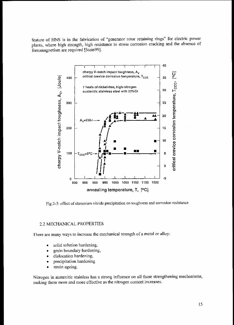
feature of HNS is in the fabrication of "generator rotor retaining rings" for electric power
plants, where high strength, high resistance to stress corrosion cracking and the absence of
ferromagnetism are required [Stein99].
O~3
>
<
w
a>c
SZ
o
oro
a.
E
siu
•*-*
ocI
>
Q.i-
ca
szo
400
300
200
100
~1 1 1 1 1 1 1—
charpy V-notch impact toughness, Avcritical crevice corrosion temperature, Tccc
7 heats of nickel-free, high-nitrogen
austenitic stainless steel with 23%Cr
AV=230J—A ftj * A 4a'
/./.
LITr-Tccc=5°C—*U
-
J L
40
35
30
25
20
15
10
Üo
o
üo
H
CO
CD
a
E0)•#-
co
'55oi_
oo
o
>0)I»
o
"cäü
o .-t:
800 850 900 950 1000 1050 1100 1150 1200
annealing temperature, T, [°C]
Fig.2-3: effect ofchromium nitride precipitation on toughness and corrosion resistance
2.2 MECHANICAL PROPERTIES
There are many ways to increase the mechanical strength of a metal or alloy:
solid solution hardening,
grain boundary hardening,dislocation hardening,
precipitation hardening
strain ageing.
Nitrogen in austenitic stainless has a strong influence on all these strengthening mechanisms,
making them more and more effective as the nitrogen content increases.
15

In this chapter only solid solution hardening by nitrogen is shown as systematic investigations
of nitrogen effect on the other four strengthening mechanism were performed during this PhD
work (the results are presented in Chapter 7).
Nitrogen in solid solution up to and beyond one weight percent strongly increases the yield
strength and the ultimate tensile strength, as shown in Fig. 2-4 [SpeidOl].
1300
laO- 1200
E 1100
CC
£ iooo
c
ai
iz 900tn
<D
w800
c
CD
*->
re
e
"5x>c
re
DC
jf
c
(1)
w
JOaj
700
600
500
400
300
200
100
I I
295 K
1 1 i i i i
-
_• _ •* ^ R„= 500+500^1* ^^"^
-
J1p^T
-
1
jtk*3» •
M
•-
DrwO r^^^,Rpo-s= 150+500,'';'
m* G Ç
m
jP o
^
I 1 1 i
Rpo.2 = y'eld strength_
Hm = ultimate tensile strength
D commercial steels
O • experimental steels
1 1 1 1
0 0.2 0.4 0.6 0.8 1.0 1.2 1.4 1.6 1.8
nitrogen content, [weight - percent]
Fig.2-4: solid solution hardening by nitrogen: effect on mechanical strength
Although there is a considerable scatter in the experimental data, a square root relationship
between strength and nitrogen concentration appears possible; the relations proposed are:
^o2=150 + 500-V^V [3]
R =500+ 500-V7V [4]
The effect on nitrogen alloying on ductility is shown in fig.2-5 [SpeidOl].
It is remarkable that such a strong increase in mechanical strength with increasing nitrogen
content does not result in a decreased ductility.This is in direct contrast to the widespread experience with other strengthening mechanisms
where strength increases always at the expense of ductility.
16
I 1 I I I
elongation to fracture of
austenitic stainless steels 295K
100
r-,90
<80
<s
3 70«Hi
Oca
•fc 60
o
§ 50
03
g> 40
O
CD
30
20
10
0 0.2 0.4 0.6 0.8 1.0 1.2 1.4 1.6
nitrogen content, weight-percent
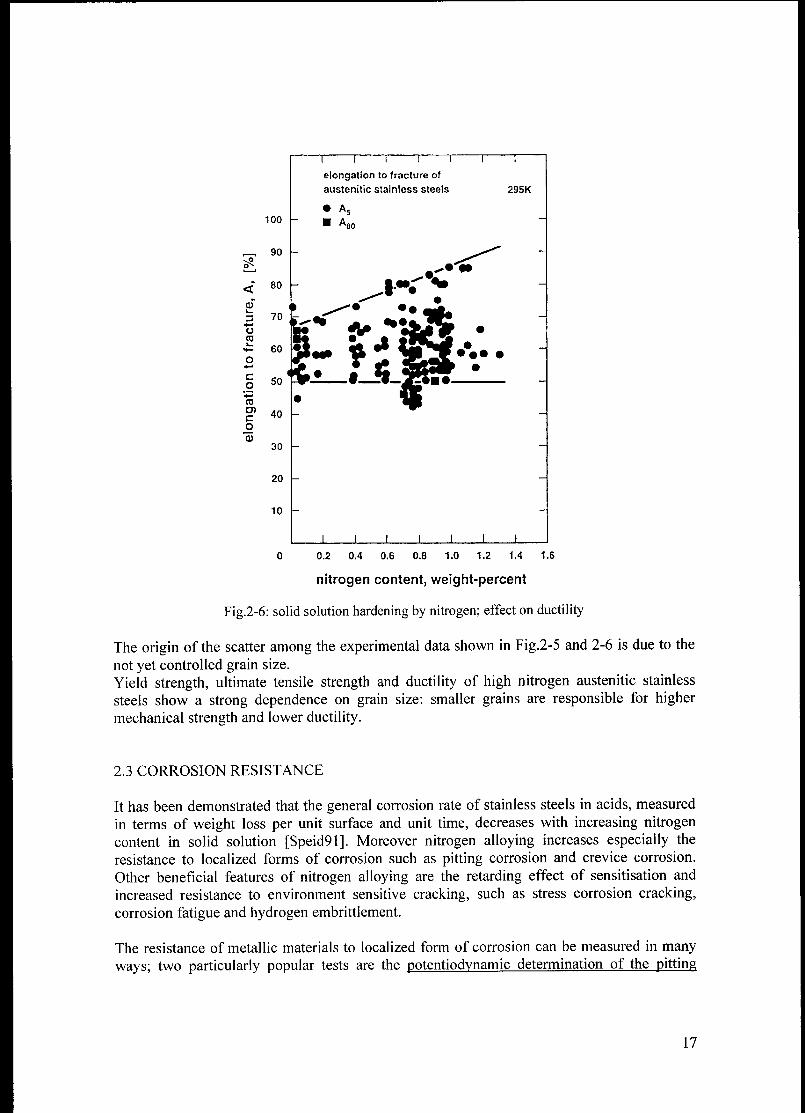
Fig.2-6: solid solution hardening by nitrogen; effect on ductility
The origin of the scatter among the experimental data shown in Fig.2-5 and 2-6 is due to the
not yet controlled grain size.
Yield strength, ultimate tensile strength and ductility of high nitrogen austenitic stainless
steels show a strong dependence on grain size: smaller grains are responsible for highermechanical strength and lower ductility.
2.3 CORROSION RESISTANCE
It has been demonstrated that the general corrosion rate of stainless steels in acids, measured
in terms of weight loss per unit surface and unit time, decreases with increasing nitrogen
content in solid solution [Speid91]. Moreover nitrogen alloying increases especially the
resistance to localized forms of corrosion such as pitting corrosion and crevice corrosion.
Other beneficial features of nitrogen alloying are the retarding effect of sensitisation and
increased resistance to environment sensitive cracking, such as stress corrosion cracking,corrosion fatigue and hydrogen embrittlement.
The resistance of metallic materials to localized form of corrosion can be measured in many
ways; two particularly popular tests are the potentiodynamic determination of the pitting
17

potential (Eplt) and the measurement of the critical temperature, that is the temperature above
which pitting corrosion or crevice corrosion is observed.
The critical crevice corrosion Tccc is the temperature above which crevice corrosion is
observed in a 24-hour immersion test in 6 percent FeCb solution.
To determine the critical pitting corrosion temperature is possible to carry out
potentiodynamic tests in 22 weight percent NaCl solution at different temperatures. Results of
potentiodynamic tests are schematically shown in Fig. 2-7, where at potentials more positive
than a critical value (Epit) the current density rises abruptly by orders of magnitude.
Metallographic observation reveals that this rise is coincident with the formation of corrosion
pits on the surface of the steel.
(fl
CoTJ
•f
C0)wL.
3O
c
o
"wov.j_
ou
roo
potentiodynamic electrochemical polarization curve
current density - potential curve
*
passivation current density
pittingpotential
trans-
passive
Ep potential
electrode potential, [V]
Fig.2-7: potentiodynamic determination of the pitting potential (Epit)
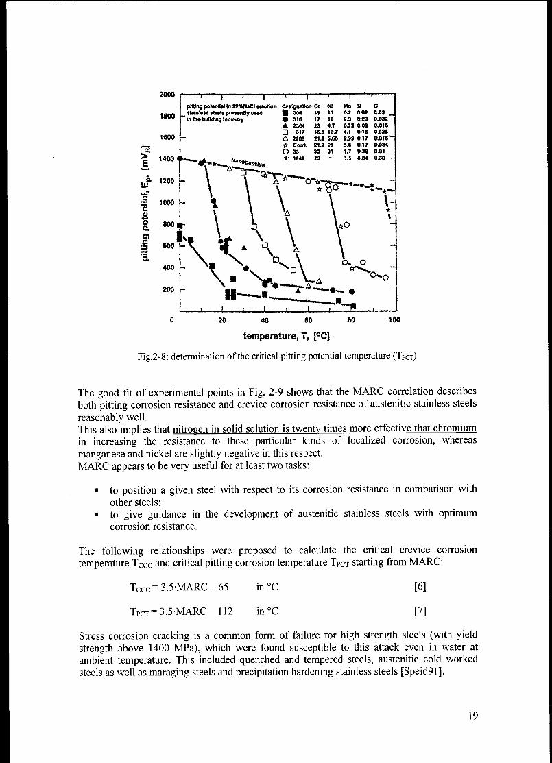
When such tests are repeated at different temperatures, the critical pitting potential changes as
shown in Fig. 2-8 [SpeidOl]. The pitting potential of each particular alloy drops below the
transpassive line at a critical temperature, that is the pitting critical temperature, Tpct-
Both tests reveal that nitrogen in solid solution is highly effective in improving the resistance
of stainless steels to pitting and crevice corrosion.
This is illustrated in Fig. 2-9 [Speid02], where the two critical temperature are plotted against
MARC (Measure of Alloying for Resistance to Corrosion, an empirical parameter dependent
on alloy composition) for a large number of different austenitic stainless steels:
MARC=Cr + 3.3Mo + 20C + 20N - 0.5Mn - 0.25Ni [5]
18
X
>
a.m
"3
2000
1800
1600
1400
1200 -
» 1000C
S,oa
mc
35a
T T
pining poUriti*) In 22*taCl »edition OetignaUor) Cr
»Uln)«i»»t«l»pr«tii!lyuM<J 30* 1»'
In R» building Induitry # 316
A 2304
317
A 220S
ô Corff.
O 33
i—
NI
tl
17 12
2J 41
t«.» 12.T
21.« 5.6«
21.2 2»
» 3«
n -
~1 ""<
Mo N C
o* o.«» am_
2.3 6.23 0.932
0.S3 0.» 0.01«
4.1 015 0U>2«
2*9 0.17 0.016
5,* 0.17 0.034
1.7 0.3» 0.01
1.5 0.8* 0.30
^5-*-M^
temperature, T, {°C]
Fig.2-8: determination of the critical pitting potential temperature (TPCT)
The good fit of experimental points in Fig. 2-9 shows that the MARC correlation describes
both pitting corrosion resistance and crevice corrosion resistance of austenitic stainless steels
reasonably well.
This also implies that nitrogen in solid solution is twenty times more effective that chromium
in increasing the resistance to these particular kinds of localized corrosion, whereas
manganese and nickel are slightly negative in this respect.
MARC appears to be very useful for at least two tasks:
to position a given steel with respect to its corrosion resistance in comparison with
other steels;
to give guidance in the development of austenitic stainless steels with optimumcorrosion resistance.
The following relationships were proposed to calculate the critical crevice corrosion
temperature TCcc and critical pitting corrosion temperature TPCT starting from MARC:
LCCC" 3.5-MARC-65 in°C [6]
Tpct=3.5-MARC-112 in °C [7]
Stress corrosion cracking is a common form of failure for high strength steels (with yield
strength above 1400 MPa), which were found susceptible to this attack even in water at
ambient temperature. This included quenched and tempered steels, austenitic cold worked
steels as well as maraging steels and precipitation hardening stainless steels [Speid91].
19

1 1 1 1 1 1 1
critical corrosion temperatures, austenites
-
1879 O1880 O
1.4562 O /SMO 254O /-
/ WSMO 654
—
33 0 /è I critical crevice
/ /-— corrosion temp.
P558 0 / <6%Fecy-
_
/ /• UB 66
critical pitting / /corrosion temp.
~
(22% NaCI) 1 /^188° -
/ •1.4562
/ • SMO 254
' /• 33
- //
316 O
- /,
• P558
/ :316T
1 1T
i i i i i
0 10 20 30 40 50 60 70 80
100
Üo
90
o
ÜÜ
80
üQ.
O /O
H
(0G) KOk.
3**
coil h(lCiCl
Eo 40+*
c
o30
C0o1-
1_
o 20
o
(0Ü 104-*
s-
ÜÜ
-10
MARC = Cr+3.3Mo+20C+20N-0.5Mn-0.25Ni
Fig.2.9: resistance to crevice and pitting corrosion in function ofMARC
Certain cold worked austenitic stainless steels with nitrogen up to 1 weight percept shown no
stress corrosion susceptibility in water at ambient temperature (and up to 80°C). For this
reason they are used for generator-rotor retaining rings in electric power stations [Stein99].
Nitrogen in solid solution increases the resistance to stress corrosion cracking in austenitic
stainless steels also in chloride solution, even in cold worked condition [Speid91]. It is well
known that in hot concentrated chlorine solutions, standard austenitic and other stainless
steels may fail due to transgranular and intergranular stress corrosion cracking. This has
resulted in a huge number of service failures with these steels and it continues to be a
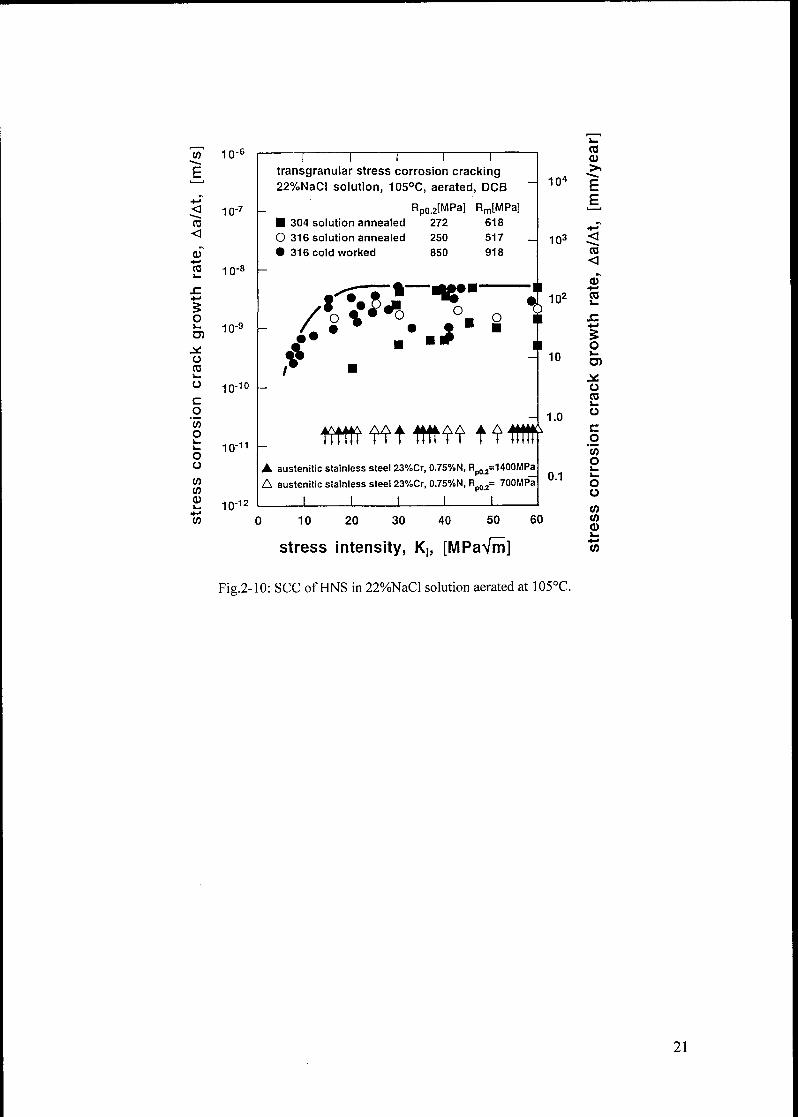
problem.In Fig.2-10 the growth rates of stress corrosion cracks in austenitic stainless steel 304 and 316
are shown for environments consisting of aerated water with 22 weight percent sodium
chloride, maintained at 105°C [Speid02].This environment is about as aggressive as that which would be expected in a seawater
cooling system in dry-out conditions. Quite generally, austenitic stainless steels crack in this
environment with crack growth rates of about 100 mm per year.
In contrast, austenitic stainless steels with 23 weight percent chromium and 0.75 weight
percent nitrogen exhibit no such stress corrosion cracking, neither in the solution annealed
condition (700 MPA yield strength) nor in the cold worked condition (1400 MPa yield
strength).
20
CO
E
<
CD*-»
CO
5ok.
Ol
Ü
cai—
o
c
o
'took.
k.
ou
toCO
CDk.
CO
10-
10"
io-;
io-!
10 10
io-11
10 12
transgranular stress corrosion cracking22%NaCI solution, 105°C, aerated, DCB
Rp0.2[MPa] Rm[MPa]304 solution annealed 272 618
O 316 solution annealed 250 517
• 316 cold worked 850 918
Vo
J"o
*
- 104
103
102
10
frtttt<r?tWmt?lW
austenitic stainless steel 23%Cr, 0.75%N, Rp02=1400MPaA austenitic stainless steel 23%Cr, 0.75%N, Rp02= 700MPa
I I I I I
1.0
0 10 20 30 40 50 60
stress intensity, Kh [MPaVm]
eu
EE
<
aï+->
03
5ok.
oCOk.
o
c
o
"53o
u
COCOCik_
4-«
(0
Fig.2-10: SCC ofHNS in 22%NaCl solution aerated at 105°C.
21
3. THEORETICAL ASPECTS OF HIGH NITROGEN
AUSTENITIC STAINLESS STEELS
So far HNS have been developed in such an extend that always more people, working in the
field of stainless steels, cannot ignore anymore their outstanding properties that now can be
properly measured and described in terms of alloy composition as shown in the previous
chapter.In spite of this well known "empirical evidence" convincing theoretical explanations for
nitrogen's role on the strengthening mechanisms and corrosion phenomena are still not yet
available. FINS under this point of view represent a very good "terrain" for further
investigations not only for metallurgists but also for physicist and chemists.
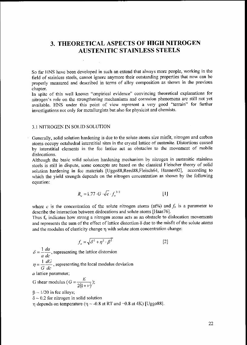
3.1 NITROGEN IN SOLID SOLUTION
Generally, solid solution hardening is due to the solute atoms size misfit, nitrogen and carbon
atoms occupy octahedral interstitial sites in the crystal lattice of austenite. Distortions caused
by interstitial elements in the fee lattice act as obstacles to the movement of mobile
dislocations.
Although the basic solid solution hardening mechanism by nitrogen in austenitic stainless
steels is still in dispute, some concepts are based on the classical Fleischer theory of solid
solution hardening in fee materials [Uggo88,Reed88,Fleisch64, Hannes02], according to
which the yield strength depends on the nitrogen concentration as shown by the following
equation:
R0=\.77-G-^-f03n [1]
where c is the concentration of the solute nitrogen atoms (at%) and f0 is a parameter to
describe the interaction between dislocations and solute atoms [Haas76].Thus f0 indicates how strong a nitrogen atoms acts as an obstacle to dislocation movements
and represents the sum of the effect of lattice distortion 8 due to the misfit of the solute atoms
and the modulus of elasticity change r\ with solute atom concentration change:
/. = ^W'ß1 [2]
8, representing the lattice distorsion
a dc
77 = , representing the local modulus deviation
G de
a lattice parameter;ß
G shear modulus ( G = —, r );
ß ~ 1/20 in fee alloys;S ~ 0.2 for nitrogen in solid solution
-q depends on temperature (r\ ~ -0.8 at RT and +0.8 at 4K) [Uggo88].
22
The factor ßrj is negligible small in comparison with 5, thus an interacting force of fo=0.2
appears reasonably correct [Uggo88].With this magnitude the obstacle force of nitrogen atoms is about ten times higher than
typical values for substation atoms, thus showing quantitatively that nitrogen atoms are very
powerful hardeners.
Nitrogen atoms have smaller atomic radius compared to carbon (0.074nm and 0.077nm
respectively) but in spite of this they cause a higher dilatation in the fee crystal lattice giving a
higher strengthening effect, that cannot be completely explained only in terms of elastic
distortion of the lattice.
Such behaviour originates from the peculiarities of electrons exchange in austenitic nitrogen
and carbon steels [Gav96].The crystal lattice of metals is formed by ionic cores (atomic nuclei and closed electronic
shells around them) and free electrons. Interactions between atoms constituting the crystal are
caused by free electrons (conduction electrons which are delocalised in the interatomic space)and the overlapping unfilled electrons shells (localised external d-electrons). Roughly, the
first ones are responsible for the metallic component on interatomic bonding (characterized by
high ductility and high toughness) and the second for covalent bond (responsible for the
brittleness).It was speculated that nitrogen atoms in austenite increase the concentration of free electrons,
i.e. enhance the metallic component of atomic interactions; on the contrary carbon atoms
contribute to the localised electron, i.e. to enhance covalent bonds [Gav96]. Higher lattice
dilatation of nitrogen austenite as compared to the carbon one is expected if a weaker covalent
component of interatomic bonding is present.
Another hardening concept is based on the assumption that short range ordering occurs
between chromium and nitrogen atoms [Byrn87, Gav96].
Nitrogen affects the distribution of alloying elements in austenitic steels through the
interstitial-substitution interactions. The distribution of solute atoms is far away from that
typical for ideal solid solutions where solute atoms do not interact with each other. The
distribution of solute atoms is determined by their interactions with the host atoms and other
solutes. These interactions affect the homogeneity of solid solution, solubility of nitrogen and,
in particular, control the temperature and sequence of precipitation from the solid solution.
It is known, for example, that Ni atoms prefer to have the iron ones as nearest neighbour in
iron-based austenite as Fe-Ni bonds are preferred in comparison to Fe-Fe and Ni-Ni ones, a
situation described as short range atomic ordering (SRO) [Gav99].
Instead, Fe-Cr alloys are prone to short-range decomposition of solid solution, i.e. clusteringof Cr atoms, as Cr-Cr bond is stronger than Fe-Cr. Even Mn and Mo in iron-based alloys are
prone of clustering.In absence of interstitials, austenitic CrNi and CrNiMn steels are prone to short range
decomposition, i.e. clustering. Alloying with nitrogen diminishes this tendency whereas
carbon enhances it, because the metallic bonds enhance the short range ordering and covalent
bonds cause the clustering.
Nitrogen atoms in austenitic steels prefer to be neighbours of solute atoms belonging to
element located left to the iron in the periodical table to form substitution-interstitial atomic
complexes, such as Mo-N, Cr-N, Mn-N-Cr. The solid solution strengthening by N in
austenitic steel is determined by the symmetry of these complexes and the strength of
distortions induced by them in the fee crystal lattice. Short-range ordering increases the flow
stress due to the disruption of the local ordered structure; because the short range ordering is
23

related to the nitrogen concentration, the yield stress increases with increasing nitrogen
content [Owen90].As pointed out in section 2.2.1 a distinctive feature of nitrogen austenite is an excellent
combination between strength and ductility and toughness.It has been speculated that this unusual effect of nitrogen on strength/ductility/toughness is
the result of the increased concentration of free electrons with increasing nitrogen content thus
enhancing the metallic component ofthe interatomic bonding [Gav96, Gav99].
The nitrogen-assisted metallic character of the atomic interaction in austenitic steels
withstands the embrittling influence of nitrogen expected for interstitial impurities.
Some authors assume that the opposite situation occurs for carbon in steels where both the
carbon-induced elastic distortion and the enhanced covalent component of atomic interaction
act as embrittling factors [Gav99]. However above a certain amount on nitrogen in solid
solution, another phenomenon appears: the ductile to brittle transition causing brittleness of
austenitic steels even at room temperature.This phenomenon is explained in more details in section 3.5, as it fixes the maximum content
of nitrogen in solid solution that can be tolerated in order to achieve high toughness at room
temperature.
3.2 NITROGEN AND PLASTIC DEFORMATION
The interaction of nitrogen atoms with dislocations plays an important role in the
strengthening of austenitic steels.
It has been reported that nitrogen atoms lock dislocations more effectively than carbon; the
binding energy between nitrogen atoms and dislocations increases with increasing the
nitrogen content in austenite, whereas such trend supposedly is not found for carbon [Gav99].
This results in a stronger obstacle for the dislocation slip.The main contribution to the interaction between dislocations and impurity atoms is provided
by elastic distortion of the lattice. The stress fields created by edge and screw dislocations
results in the formation of interstitial clouds in the vicinity of the nuclei of such dislocation
(Cottrel clouds). In nitrogen austenitic steels the formation of Cottrell clouds, obeying the
exponential temperature dependence (as reported by many authors [Gav99,Uggo91,Uggo88])is the controlling mechanism for interstitials-dislocation interaction. A further contribution is
the chemical interaction, i.e. the formation of Suzuki's clouds at stacking faults.
Even if nitrogen atoms induce higher distortion in the fee austenite than the carbon ones, the
elastic contribution to the interaction of interstitial atoms with dislocations in austenitic steels
is not a unique factor determining the pinning of dislocations.
Additional dislocation pinning is caused by electrostatic interaction between interstitial atoms
and dislocations. It has been speculated that nitrogen atoms in austenite are negatively
charged and carbon atoms carry a positive electric charge [Gav99], whereas dislocation nuclei
are positively charged. Therefore an electrostatic attraction between nitrogen atoms and
dislocations has to exist in addition to the elastic one, whereas in the carbon austenite, the
elastic attraction, as compared to nitrogen, has to be counterbalanced by the electrostatic
repulsion.These small additions of opposite sign to the prevailing elastic interaction can possibly
explain the observed higher pinning of dislocation in austenitic steels by nitrogen atoms as
compared to carbon ones.
24
Nitrogen in solid solution produces also remarkable change in dislocation structure during
plastic deformation [MÜ1193].While nitrogen free austenite exhibits a homogeneous cellular dislocation structure during
plastic deformation, nitrogen assists planar dislocation and deformation twinning; both factors
resulting in higher work hardening rate and response to ageing.
According to some scientists, this change in the slip behaviour can be explained by the effect
of nitrogen on the stacking fault energy (SFE) [Gav88,Gav99,Schr75].Dislocations in austenitic steels are usually split, i.e. they consist of stacking faults limited by
two partial dislocations. Stacking faults are errors in a normal sequence of atomic planes
(ABCABC... of the fee or ABAB.... of the hep lattice).The SFE depends strongly on the chemical composition of austenitic steels, although no
quantitative relationship has been proposed until now.
Lower stacking fault energy leads to wider partial dislocation separation, reduced cross-slipand climbing, making planar slip the most common way of deformation.
Low SFE also leads to a pronounced twinning during deformation, making this deformation
mechanism possible even for low strain applied.After heavy deformations, many very fine deformation twins are observed. Twins within
twins are generated, in a process described as "second order twinning" activated by the stress
field of primary twins [Müll94b]. Both primary and secondary twins are effective obstacles
for moving dislocations and further twinning, and therefore contribute effectively to cold
work hardening.
Planar slip is attributed not only to low stacking fault energy but also to short-range atomic
order in austenitic nitrogen steels.
Short range ordering in the alloys assists planar slip because each successive dislocation
needs a lower stress to pass over the slip plane as compared to the first one which passes
through the ordered crystal and consumes an additional energy to shift the atoms from the low
energy sites.
Thus, in spite of the real mechanism involved, planar slip and twinning appear to be the two
main features of deformed high nitrogen austenite responsible for high flow stresses and high
work hardening rates observed in high nitrogen deformed alloys.
3.3 NITROGEN AND GRAIN BOUNDARY
The yield strength of high nitrogen austenitic stainless steels in function of grain size is
usually expresses by the Hall-Petch equation:
where R0 is the friction stress for dislocation movement inside the grains, ky is a coefficient
describing the effectiveness of grain boundary hardening and d is the average grain size.
The nitrogen contents and the temperature markedly affect ky [Hannes02].With higher nitrogen contents the grain size hardening becomes stronger; at low temperatures
the grain size hardening of nitrogen is more effective.
At high temperature the effect of nitrogen is small and disappears at about 550°C when
recovery takes place [Uggo88].
25
Many theories were proposed to explain the Hall-Petch equation; they can be divided in three
main groups based on the critical role of:
1. planar dislocation arrays,
2. work hardening,3. grain boundary sources.
1. Planar dislocation arrays theories
Grain boundaries are obstacles to dislocation movement. Slip in one grain of a polycrystalline
material does not spread into a neighbouring grain by simply forcing a dislocation through the
boundary. Hall (1951) and Petch (1953) postulated the formation of dislocation pile-ups at the
grain boundaries causing a stress concentration x* = nx at the head ofthe dislocation pile-ups,
where n is the number of dislocations in the pile-up and x is the shear stress applied. If Xj is
the friction stress inside the grains the stress concentration becomes x* = n(x - x;).
Plastic deformation will occur in the next grain if x* > m x0 where x0 is the critical shear stress
necessary to unlock the dislocation source in the adjacent grain and m is an orientation factor
(Cottrel 1958).The number n of dislocation in the pile-up of length L can be calculated by:
n =(t-t.) [4]
b-GK ''
where b is the Burgers vector and G is the shear modulus.
If L is proportional to the average grain size c/then the Hall-Petch relationship is found:
Tf=T,+
t* =n{T-Tl)>m-T(l
[5]
rnu
\1/2'G-b-m-T„ \
n Jd
where x/is the flow shear stress.
Multiplying equation [5] with the average orientation factor of fee polycrystalline materials,
the Taylor factor 3.06, the relation [5] is equal to [3] with:
Rp02 =3.06- rf
R„=3.06-t,
G-b-z..A:,, =3.06y
71
2. Work hardening theories
In the cold work hardening model one postulates a stress independent ct0, a parabolic stress-
strain relation a ~ Vs and a linear relation between the Hall-Petch slope ky and the square root
of strain, ky ~ Vs. A linear relation between the yield stress and the square root of the
dislocation density is accepted as an experimental fact [Honey81]. According to the work
hardening model, the dislocation density is increased with decreasing grain size according
26
yr which leads to the Hall-Petch relation and therefore the term ky -d1/2 is attributed to
work hardening.This model was supported by the theory proposed by Ashby [Ashby70], in which a higher
dislocation density at the grain boundaries as compared to the grain core can explain
strengthening by a barrier effect of these grain boundary layers of increases dislocation
density leading to a grain size dependent contribution to the work hardening of polycrystalline
materials.
3. Grain boundary sources
In the grain boundary source theory the Hall-Petch relation is determined by the capacity of
grain boundaries to emit dislocation under loading [Li70]. This approach does not require a
stress concentration created by pile-ups and in contrast to the work hardening model the hall-
Petch slope ky does not depend on the strain.
Most modern attempts to understand the effect of nitrogen and temperature on the Hall-Petch
coefficient ky are based on the pile-up of dislocation on grain boundaries theories.
In high nitrogen austenite the slip behaviour of the dislocations becomes more planar with
increasing nitrogen content, planar slip is expected to increase the grain boundary efficiency
to look the dislocations because preventing cross-slip and others dynamic recovery processes
the grain boundary becomes a more difficult obstacle to be overcome. The grain boundary
hardening contribution to the yield strength of high nitrogen austenitic steels can be calculated
in this way [Uggo88, Uggo92b]:
ARP02 = 8 + 75
v823
cN4d y 4d
J
Cn nitrogen concentration in weight percent and d average grain size in mm.
Recently, taking into account that nitrogen atoms in austenite reveal a strong interaction with
dislocations (more than carbon), a new theory based on the Cottrell's model was proposed
[Gav99]. According this new model the contribution of nitrogen to grain boundary
strengthening is provided by a strong interaction of nitrogen atoms with dislocations. Such
interaction can be strong enough to lock dislocation sources, which have to be initiated in
adjacent grains for the transfer of plastic deformation from one grain to others, a process that
requires an increased applied stress.
3.4 STRAIN AGEING HARDENING
A low temperature heat treatment on cold worked high nitrogen austenitic stainless steels, in
the range 300-600°C, results in a significant increase in strength.
Depending on nitrogen content and amount of cold deformation a strength improvement up to
500 MPa can be achieved [Uggo91]. This strengthening is caused by "strain ageing" as a
results of a chemical interaction between nitrogen atoms and dislocations.
27
The chemical interaction is determined by the enhanced nitrogen solubility in the stacking
fault. The binding energy is influenced by the width of dislocation separation. Assuming that
nitrogen reduces the stacking fault energy, a stronger interaction at higher nitrogen contents is
expected. The segregated nitrogen atoms in the stacking fault again reduce the stacking fault
energy, leading to a wider separation of the partial dislocations and therefore to reduced
energy of the whole dislocation arrangement. Thus, the nitrogen segregation ("Suzuki
atmosphere") will pin the dislocations.
At room temperature the nitrogen atoms are more or less immobile. Dislocations generated
during cold deformation are not pinned and dislocations are still mobile. After ageing at low
temperature Suzuki atmosphere are formed, yielding strong dislocation pinning. These pinned
dislocations will acts as a barrier against subsequent deformation. This results in an increase
in strength.At temperature above 600°C nitrides precipitate, resulting in a decrease in dislocation pinning
and a corresponding decrease in strength; whereas below a certain temperature, approximately
300°C, diffusion of nitrogen atoms practically ceases to occur within any useful time frame.
Therefore, in order to maximize the strength, a proper combination of time and temperature
has to be found [Uggo91].
3.5 TOUGHNESS AND DUCTILE TO BRITTLE TRANSITION
Up to 0.8 weight percent nitrogen in solid solution the fracture toughness of solution annealed
austenitic steels remains very high (>200 MPa-m"1/2)] when measured at ambient temperature
[Speid91]. However at cryogenic temperatures, a ductile to brittle transition is observed
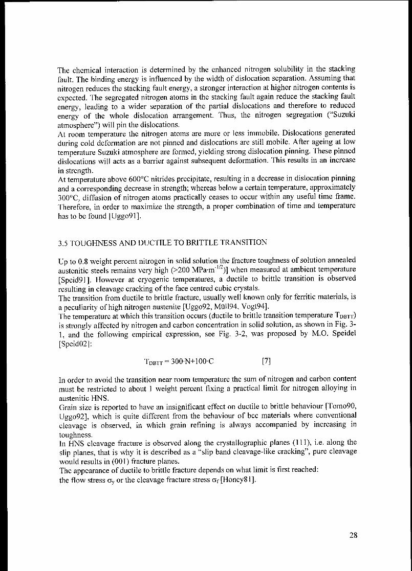
resulting in cleavage cracking ofthe face centred cubic crystals.The transition from ductile to brittle fracture, usually well known only for ferritic materials, is
a peculiarity of high nitrogen austenite [Uggo92, MÜ1194, Vogt94].The temperature at which this transition occurs (ductile to brittle transition temperature TDBtt)
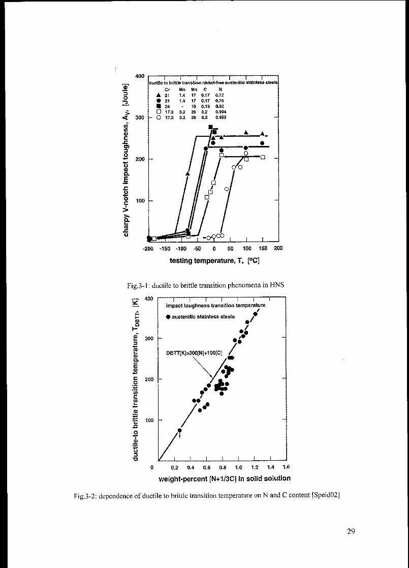
is strongly affected by nitrogen and carbon concentration in solid solution, as shown in Fig. 3-
1, and the following empirical expression, see Fig. 3-2, was proposed by M.O. Speidel
[Speid02]:
Tdbtt = 300-N+100-C [7]
In order to avoid the transition near room temperature the sum of nitrogen and carbon content
must be restricted to about 1 weight percent fixing a practical limit for nitrogen alloying in
austenitic HNS.
Grain size is reported to have an insignificant effect on ductile to brittle behaviour [Tomo90,
Uggo92], which is quite different from the behaviour of bcc materials where conventional
cleavage is observed, in which grain refining is always accompanied by increasing in
toughness.In HNS cleavage fracture is observed along the crystallographic planes (111), i.e. along the
slip planes, that is why it is described as a "slip band cleavage-like cracking", pure cleavage
would results in (001) fracture planes.The appearance of ductile to brittle fracture depends on what limit is first reached:
the flow stress ay or the cleavage fracture stress Of [Honey81].
28
400
3O
mCO01
c
3p
300
Cr
21
• 21 1.4
24
G 17.2 3.2 26 Q.2
- O 17.2 3.2 26 0.3
** 200
OCOa
%C
>»
k.
CC4=U
100
—] 1 i j r——ï 1—ductile to brittle transition nickei-ireo austenitic stainless steels
Mo Mn C N
1.4 17 0.17 0.72
17 0.17 0.76
1S 0.1S 0.82
0.994
0.995
-200 -150 -100 -50 50 100 150 200
testing temperature, T, [°C]
Fig.3-1 : ductile to brittle transition phenomena in HNS
r-, 400
CDQ
i
2CDCL
CO
co.m.
CCO
0i
300
200
•"£ ioo
o
u3
•a
—r——i r—i 1 r
Impact toughness transition temperature
• austenitic stainless steels
DBTT[K]=300[NJ+100[C]
_L
0 0.2 0.4 0.6 0.8 1.0 1.2 1.4 1.6
weight-percent [N+1/3C] in solid solution
Fig.3-2: dependence of ductile to brittle transition temperature onN and C content [Speid02]
29
The fracture mechanism in high nitrogen austenite is considered as slip band and/or twin
boundary cracking, caused by two peculiarities these steels:
a strong planarity of the dislocation structure (dislocations are concentrated on distinct
slip planes) and a high density of deformation twins, loading to a high level of internal
stresses and therefore to an apparent decreases of the (111) fracture stress af,
a strong temperature dependence of the yield stress, hence flow stress ay [Uggo88,
Uggo92] (for normal low nitrogen austenite the cleavage fracture stress is rather high
and slightly depending on the temperature, whereas the flow stress changes weakly
with the temperature, thus cleavage fracture usually does not occur).
In high nitrogen austenitic steels formation and growth of cleavage fracture is strongly
connected to locally concentrated plastic deformation. A cleavage crack could be formed
because of the intersection between slip bands and deformation twins with grain boundaries,
slip bands and twin boundaries.
The cleavage fracture stress can be calculated by means of this relation:
Ky Hall-Petch slope coefficient, G shear modulus, y surface energy, d grain size, A constant.
Accordingly, the cleavage fracture stress will be low with low surface energy y, high Ky and
coarse grain.
Assuming a slip plane fracture as a fracture mode, the following mechanism was proposed
[Uggo92].In a favourably oriented grain a slip band is formed. The slip band is the more pronounced the
higher the nitrogen content. Since cross slip is restrained, the plastic deformation is restricted
to this peculiar area of structure; i.e. the density of piled up dislocations increases rapidly. As
a consequence of this high density of lattice defects, high internal stresses may occur. A
remarkably high stress concentration results at intersections of slip bands and twins. In
addition to the applied tensile force component, these deformation induced internal stresses
cause a final cleavage separation in the tensile mode.
This implies that the plastic deformation necessary for crack forming is lower in steels with
distinct planar slip; because of the slip (and stress) concentration i.e. a macroscopically
smaller deformation may lead to crack formation in high nitrogen steels. Since the work done
in deformation has to be taken into account for the calculation of the specific "surface energy
y", y is expected to be smaller with high nitrogen content. Furthermore, a temperature
dependence of y is expected, because it is assumed that low temperatures increase the
concentration of slip on distinct planes. Applied to high nitrogen steels, this means that the
fracture stress Of decreases with increasing nitrogen content and decreasing temperature, if the
grain size d remains constant.
On the base of these mechanisms the effect of nitrogen and grain size on the ductile to brittle
transition can be understood comparing the flow stress ay and the cleavage fracture stress Of.
Low nitrogen content leads to a low flow stress with weak temperature dependence and the
fracture strength is high. High nitrogen content, on the other hand, results in high flow stress
30

and a low fracture stress. Leaving the grain size constant, this causes a shift of the Tdbtt to
higher values according to Fig. 3-3a.
A change in grain size, leaving the nitrogen content constant, has no strong effect on the
transition temperature. Finer grain affects the flow stress and the cleavage fracture stress in
the same way; it shifts both curves to higher values. The intersection of the two curves, and
accordingly the ductile to brittle transition temperature, remains approximately at the same
level of temperature (Fig. 3-3b).
<*> Nlug a>
CO ICO t
0) '
t_
to
<*VNI(W \
-A
tffNhlg COCO0)
to
a, Dh.g b)
°V usmail^fÇwnall
°rDbm
AXDBÏ1'
temp.
AT,DBTT
temp.
Fig.3-3: schematic effect of nitrogen content (a) and grain size (b) on the ductile to brittle transition
temperature TDbtt (stress state and loading rate effects not included)
3.6 CHEMICAL PROPERTIES
Passivity is the origin of good corrosion resistance of stainless steels and it is based on thin
surface film formation acting as diffusion barrier and having specific electrical properties
exerting, thus, a profound influence on the corrosion rates of metals and alloys. Passive
properties of the film are related to its chemical composition, thickness, crystal and defect
structure, electrical properties and mechanical properties.Four existing hypothesis interpreting the corrosion behaviour of nitrogen steels were
summarised by Speidel [Speid91]:
• nitrogen segregates to the metal surface as other metal elements dissolve preferentially,
leaving a nitrogen enrichment at the surface improving the passivity;• nitrogen is incorporated into the passive oxide film to form a dense protective oxynitrided
layer;• nitrogen in the steels dissolves to form nitrides or nitrates which act as local inhibitors;
• nitrogen dissolves during corrosion reaction to form ammonia, which increases pH and
renders the electrolytes at the pit sites, inside the crevices and cracks less acid.
Corrosion resistance of stainless steels is based on their chromium content, which after certain
heat treatments can locally decrease on the grain boundaries due to carbide/nitride
precipitation (sensitization) leading to intergranular corrosion attack.
The high resistance to sensitization of high nitrogen austenite is related to [Hänn99, Gav99]:
31
• weak tendency of nitrogen to form grain boundary segregations in steels as compare to
carbon;
• retardation of nucleation and/or growth of Cr-rich carbides (a more homogenous solid
solution alloying with nitrogen is achieved by short range ordering);
• changes in the activity of Cr in equilibrium with the carbide;
• nitrogen enhanced passivation, i.e. more Cr-depletion is required to failure;
• prevention of a' martensite formation along the grain boundaries due to the austenite
stabilizing effect ofN.
The beneficial effect of N on carbide sensitization is only possible if the solubility limit ofN
is not exceeded, since &2N precipitation may lead to localize depletion in Cr and a reduction
in corrosion resistance. Therefore, in general this retarding effect is only observed up to a
certain content ofN.
In high nitrogen steels, N has been observed to retard the precipitation of intermetallic phases,
which are also very detrimental for corrosion properties due to local Mo and Cr depletion in
the matrix immediately surrounding the intermetallic phases.
Pitting type of corrosion precedes SCC of austenitic stainless steels in hot chloride solutions
and therefore the elements that suppress pitting corrosion such as Mo and N should also
reduce the susceptibility to SCC in these environments.
Also the increased austenite stability due to alloying with nitrogen, which does not transform
into martensite upon severe plastic deformation, may explain the increased resistance to stress
corrosion cracking of cold worked nitrogen austenite.
32
4. PRODUCTION ROUTES OF HIGH NITROGEN
STAINLESS STEES
Melting practice for High Nitrogen Steels, since the beginning of their invention has two
problems:
1. how to introduce high nitrogen contents into the melt;
2. how to keep nitrogen in solid solution during the process of solidification thus
avoiding porosities in cast ingots.
To overcome these problems, nitrogen solubility evaluation models in the liquid state and
solid state as well as different manufacturing routes were developed.
Nitrogen can be added in many ways.
It may come from molecular or ionised gas atmosphere at normal or elevated pressure, it may
be offered by nitride ferro-alloys (FeCrN, FeMnN, FeVN, CrN, MnN) or highly concentrated
ceramic nitrides (S13N4). Introduction may be directly into the melt or indirectly through the
slag [Feich99].
Independently of the nitrogen source used, the dissolution of nitrogen in iron-based alloys can
be described by the reaction:
where the equilibrium constant KN for reaction [1] can be written as
aN _fN-[%N]"'iT'ir^
[]
aN activity ofN dissolved in alloy;
Pn2 nitrogen partial pressure;
7n nitrogen activity coefficient;
[%wt] nitrogen solubility in weight percent.
Nitrogen solubility for pure iron is very small (~0.045wt% @ 1550°C lbar) but may be
significantly improved trough the addition of the alloying elements which decrease the
nitrogen activity^ such as chromium and manganese.
Detailed evaluations related to study the influence of different alloy elements on the nitrogen
solubility in pure iron [Schii67] as well as in multicomponent iron base materials were carried
out [Zhen91, Kunz94, KowOO], investigating the basic behaviour of the alloys
Zheng [Zhen91] quantified the influence of the alloying elements in the solid phases.
Equations [3] and [4] give the mathematical description of the thermodynamic influence of
the alloying elements, the temperature and the partial pressure as given by Zheng:
log/, =2>* -M+Itf -[Vox,]2 +5>** .[%x,].[%r;] [3]
33
log[%tf] = log*„ -log/„ + ^\ogPN [4]
The interaction parameters eN and tn for different alloy combination were determined by
Zheng and may be found in Appendix 2.
Based on these theories and investigations, it was possible to evaluate the nitrogen solubility
in the alloys of interest.
Nowadays all this information is available in software packages like ThermoCalc, based on
databank of experimentally obtained data in which, the accuracy of the results is directly
connected to the accuracy and exhaustiveness of the databank used.
At atmospheric pressure the solubility of nitrogen is function of alloy composition and
temperature. During cooling nitrogen solubility increases with decreasing temperature, but
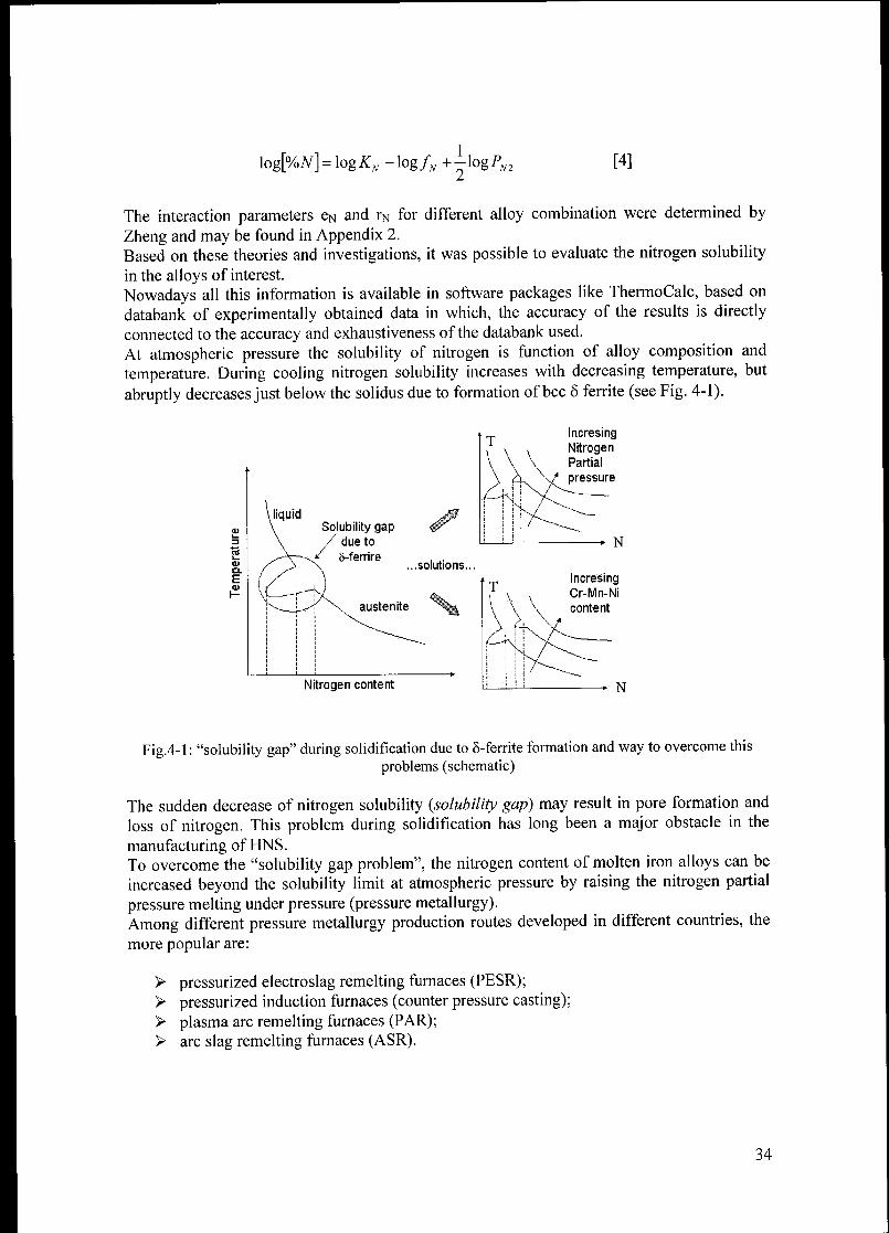
abruptly decreases just below the solidus due to formation of bec ô ferrite (see Fig. 4-1).
Solubility gapdue to
8-ferrire...solutions.
austenite
IncresingNitrogenPartial
pressure
IncresingCr-Mn-Ni
content
Nitrogen content
Fig.4-1 : "solubility gap" during solidification due to 8-ferrite formation and way to overcome this
problems (schematic)
The sudden decrease of nitrogen solubility (solubility gap) may result in pore formation and
loss of nitrogen. This problem during solidification has long been a major obstacle in the
manufacturing of HNS.
To overcome the "solubility gap problem", the nitrogen content of molten iron alloys can be
increased beyond the solubility limit at atmospheric pressure by raising the nitrogen partial
pressure melting under pressure (pressure metallurgy).
Among different pressure metallurgy production routes developed in different countries, the
more popular are:
> pressurized electroslag remelting furnaces (PESR);> pressurized induction furnaces (counter pressure casting);> plasma arc remelting furnaces (PAR);> arc slag remelting furnaces (ASR).
34
The first two are routinely used among HNS producers around the world, whereas the last two
have found limited applications.Another way to overcome the "solubility gap" is to use the powder metallurgy route, as the
nitrogen solubility in HNS is always higher in the solid phase than in the liquid state, see
Fig.4-1.Therefore, instead of adding nitrogen in the liquid state it may be introduced into a steel
powder thermally by diffusion or mechanically by milling; subsequently powder is compacted
to give a pre-shape or a near-net shape products with a wide range of nitrogen content.
While all these manufacturing routes sounds quite "exotic" and "expensive"; this can explain
why in spite of a good knowledge, accumulated since the end of the 60s, on favourable effects
by nitrogen alloying in austenitic stainless steels, HNS have been not extensively used and
adopted in large quantities yet.
This situation is expected to change in the near future if HNS could be made using
conventional equipments, increasing the nitrogen solubility at atmospheric pressure and
avoiding the "solubility gap" during solidification.
This can be done with a carefully chemical composition, adding elements with a negative
interaction parameter and avoiding those of positive sign; in this way nitrogen activity is
lowered resulting in an increased solubility by more than two orders of magnitude. Fig.4.2
shows the effect of different alloying elements on nitrogen solubility
StrojZS
formers
Strong
Reducers
ofN-Sotubilitv
Balanced
N-Solubilityand Nitride
Formation,
f£&
Fig.4-2: suitable elements for HNS metallurgy arranged in the periodic system [Feich99]
The strongest nitrogen solubility promoter's elements: titanium, zirconium, vanadium and
niobium (see Fig.4.2), can hardly be used, because of low solubility of their respective
nitrides in the solid state, which may lead to indissoluble embrittling precipitates (coarse
primary nitrides form directly into the liquid).
Chromium, manganese and molybdenum are the only elements that increase the nitrogen
solubility with a moderate tendency to form nitrides (compare the others ones). Among them
Cr and Mn are the most effective.
In order to increase the nitrogen solubility up to 0.5 weight percent, chromium contents higher
than 25 weight percent are necessary, but it is not possible to add so much chromium alone
because of intermetallic phases precipitation.The situation for high chromium contents does not improve adding molybdenum, because
also this element stabilizing the bcc structure increases the risk of pore formation.
35
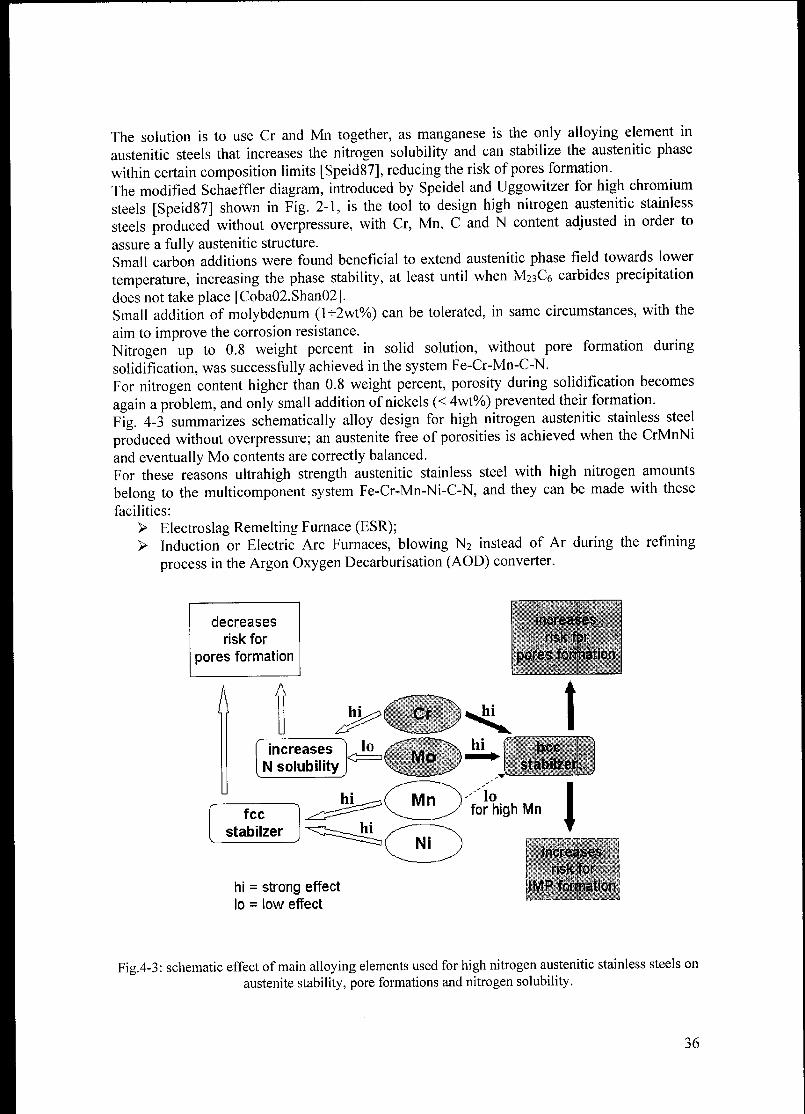
The solution is to use Cr and Mn together, as manganese is the only alloying element in
austenitic steels that increases the nitrogen solubility and can stabilize the austenitic phase
within certain composition limits [Speid87], reducing the risk of pores formation.
The modified Schaeffler diagram, introduced by Speidel and Uggowitzer for high chromium
steels [Spcid87] shown in Fig. 2-1, is the tool to design high nitrogen austenitic stainless
steels produced without overpressure, with Cr, Mn, C and N content adjusted in order to
assure a fully austenitic structure.
Small carbon additions were found beneficial to extend austenitic phase field towards lower
temperature, increasing the phase stability, at least until when M23C6 carbides precipitation
does not take place [Coba02,Shan02].Small addition of molybdenum (K2wt%) can be tolerated, in same circumstances, with the
aim to improve the corrosion resistance.
Nitrogen up to 0.8 weight percent in solid solution, without pore formation during
solidification, was successfully achieved in the system Fe-Cr-Mn-C-N.
For nitrogen content higher than 0.8 weight percent, porosity during solidification becomes
again a problem, and only small addition of nickels (< 4wt%) prevented their formation.
Fig. 4-3 summarizes schematically alloy design for high nitrogen austenitic stainless steel
produced without overpressure; an austenite free of porosities is achieved when the CrMnNi
and eventually Mo contents are correctly balanced.
For these reasons ultrahigh strength austenitic stainless steel with high nitrogen amounts
belong to the multicomponent system Fe-Cr-Mn-Ni-C-N, and they can be made with these
facilities:
> Electroslag Remelting Furnace (ESR);> Induction or Electric Arc Furnaces, blowing N2 instead of Ar during the refining
process in the Argon Oxygen Decarburisation (AOD) converter.
Fig.4-3: schematic effect of main alloying elements used for high nitrogen austenitic stainless steels on
austenite stability, pore formations and nitrogen solubility.
36
5. AIM OF THIS PhD PROJECT
One target of this ph.D. project was to show how new ultrahigh nitrogen austenitic stainless
steels, containing up to 1.4 weight percent nitrogen in solid solution, can be designed to be
made by "ingot metallurgy" without overpressure, using conventional equipment, with
appropriate amounts of chromium and manganese and small addition of nickel (to avoid pores
formation at the higher nitrogen content during solidifications), the basis being iron.
The starting point for these researches was the high nitrogen austenitic stainless steel with
composition Fe23Crl6Mn0.17C0.72N, developed at the ETH Institute of Metallurgy by Prof.
Markus O. Speidel.
High strength austenite can be achieved superimposing different strengthening mechanism,
such as solids solution hardening, grain boundary hardening, dislocation hardening and static
strain ageing.With the aim to optimise each mechanism a number of questions arise which need to be
elucidated.
Taking into account that a minimum carbon content is necessary to extend the austenitic
single phase region at low temperature, is it possible to decrease the carbon content and
increasing nitrogen in solid solution avoiding the ductile to brittle transition near room
temperature, getting the best from solid solution hardening by nitrogen?
Is it possible to obtain small grains adding niobium and vanadium without adverse effects on
toughness and corrosion resistance?
Which are the minimum grain sizes that can be achieved by means of static recrystallization
heat treatment in bulk materials and in small samples?
Does a "practical limit" for grain boundary hardening exists beyond which this strengthening
mechanism cannot be used due to adverse effects on some mechanical properties like
ductility? toughness ?
Is the ductile to brittle transition temperature really independent on grain size?
Which is the highest mechanical strength in high nitrogen austenitic stainless steels that can
be achieved superimposing all four strengthening mechanism (solid solution hardening, grain
boundary hardening, dislocation hardening, precipitation hardening)?
Which is the behaviour of high nitrogen steels during hot rolling?
Is it possible to improve furthermore the mechanical strength by dislocation hardening using
this processing route for wrought products?
Answers to these questions can be found in what follows.
37
6. HIGH NITROGEN AUSTENITIC STAINLESS STEELS
MICROALLOYED WITH NIOBIUM AND VANADIUM
6.1 SCOPE
In this chapter results of investigations related to increase the mechanical strength, without
adverse effect on toughness, in high nitrogen austenitic stainless steels with fix nitrogen
content in solid solution by grain boundary hardening are described.
In order to obtain small austenitic grains the primary grain refining mechanism is the
recrystallization of austenite during hot deformation. However, in austenite devoid of second
phase particles, the high temperature involved in hot rolling or hot forging leads to marked
grain growth with the result that grain refining during subsequent working is limited.
The situation is greatly improved if fine particles (such as carbides, nitrides or carbonitrides)
are introduced into the austenitic matrix.
The theory of grain boundary pinning by particles defines the critical size of particles below
which pinning is effective. The control of grain size at high austenitizing temperatures
requires as fine precipitates as possible on the grain boundaries [Honey81].
The best grain refining elements are strong carbide and nitride formers, such as niobium and
vanadium. As both carbon and nitrogen are present in high nitrogen austenitic stainless steels,
the most effective grain refining compounds are the respective carbonitrides.
More stable nitride former elements, such as titanium and aluminium, were not considered in
this work because all alloys were produced by ingot metallurgy at atmospheric pressure and
by this route it is not possible to avoid formation of TiN and A1N in the liquid phase. These
nitrides, due to a different specific weight in comparison with the rest of the melt, float on the
liquid and thus are not homogeneously distributed in the austenite after the solidification.
Indeed after casting they are coarse and cannot be dissolved by a subsequent heat treatment,
resulting in poor mechanical and chemical properties.Vanadium and niobium react less harmfully than titanium and aluminium in this respect.
If niobium and vanadium carbonitrides are useful to control the grain growth, their
precipitation into the austenitic matrix results in a toughness reduction, which can be tolerated
only if it is not severe. To achieve this goal the degree of solubility that such stable
compounds have in austenite is important and it was investigated.
In carbon-containing high nitrogen austenitic steel, carbon is used to extend the austenite
single phase region, but high carbon contents may result in M23C6 carbides precipitation at
low temperature, with adverse effect on toughness. A compromise between these two carbon
effects was analysed in order to still have high toughness values.
6.2 MATERIALS AND METHODS
On high nitrogen low nickel austenitic stainless steels with 0.75wt% nitrogen in solid
solution, the effect of different carbon contents (0.08 - 0.2wt%), niobium contents (0.02 -
0.3wt%) and vanadium contents (0.3 - lwt%) on strength, toughness, ductile to brittle
transition and corrosion resistance was investigated.The thermal stability of the austenite against precipitation of Cr2N and/or M23C6 on the grain
boundaries was investigated by means of thermodynamic simulation using the software
38
package ThermoCalc (the new "TCFE Thermocalc Alloy Database for Steel 2000" was used)
and experimental tests.
The chemical composition of alloys investigated is reported in Tab. 6-1 (Appendix 4).
In alloys containing vanadium the nitrogen content was chosen in order to have 0.75wt%
nitrogen in solid solution and the rest in compound state as vanadium carbonitrides;
depending on vanadium content this amount of nitrogen was chosen in stoichometric way.
All the alloys were cast into 3 Kg ingots, homogenized at 1250 °C for 6 hours and water
quenched, then hot forged to plates with a thickness of 16 mm. Sections were cut from the hot
forged plates and solution annealed at different temperatures for one hour and water
quenched. After each heat treatment, specimens for tensile test, impact energy test and
metallographic investigation was machined.
In order to study the influence on the mechanical strength of grain size, heat treatments of
static recrystallization on cold worked round bars with a diameter of 10 mm were carried out.
Cold deformation was performed using a swage forging machine starting from 15 mm
diameter bars, machined from the initial hot forged plates, for a final degree of cold working
of 56%. The holding time used during SRX heat treatment was in the range oftwenty minutes
to four hours.
6.3 RESULTS
6.3.1 NITROGEN AND CARBON IN SOLID SOLUTION
6.3.1.1 TOUGHNESS
The results of impact energy tests performed on alloys with different carbon content are
shown in Fig. 6-1.
Curves in Fig. 6-1 show a same typical trend: for annealing temperature higher than a critical
value the toughness, measured as impact energy, is high and tend to remain more or less
stable with increasing the annealing temperature. As the annealing temperature decreases
below a critical values a suddenly drop in impact toughness toward very low levels is
observed.
Metallographic observations and thermodynamic simulations by Thermocalc have shown that
such behaviour at low temperatures is due to precipitation of M23Q carbides or Cr^N nitrides
along the grain boundary, with typical morphology shown in Fig.6-2a/2è. Chromium nitrides
were found to precipitate in cellular form (a morphology called "false perlite") in agreement
with the literature of precipitation phenomena in HNS (see Appendixl).
The highest toughness levels are typical of a fully austenitic microstructure.
The curves in Fig. 6-1 show little difference in toughness above 1000°C for different carbon
content, whereas big difference appears at lower annealing temperatures.
These results can be understood analysing the carbon effect on the single-phase y region in
phase diagram for the system Fe-Cr-Mn-C-N calculated by ThermoCalc.
Phase diagrams in Fig. 6-3 show how carbon extends the single-phase austenite field. As a
drawback the line for M23C6 carbides precipitation shifts towards high temperature with
increasing carbon content (compare Fig. 6-3a/b/c/d). For carbon content near to 0.1wt%
(Fig.6-3c) such line is tangent at the deepest point of the austenitic field (point A). Under this
condition the highest thermodynamic stability of the austenite is achieved, being limited at
low temperature only by Cr2N precipitation function of the nitrogen content.
39
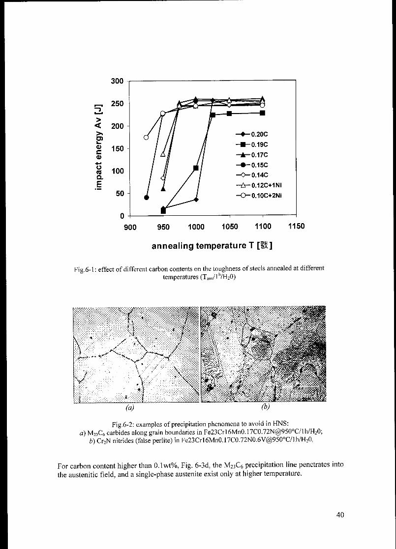
250 a—^>fl ^—£*^j£l_^„^=tN
-J ^^Q-£-"^-i / Ci
l__J
> // y/ iy< 200
/ / // f
ö / I -*-0.2QC
k_
oc
CD
150/ //
//-B-0.19C
/ / // -A-0.17C
Ü/ i/ / —0-0.150
(Q 100 / // ./ /a /Of / / —0—0.14C
b£ /
-&-0.12C+1Ni
50
0
é / !^ -O-0.10C+2NÎ
900 950 1000 1050 1100 1150
annealing temperature T [IÜ]
Fig.6-1 : effect of different carbon contents on the toughness of steels annealed at different
temperatures (Tann/l'7H20)
Fig 6-2: examples of precipitation phenomena to avoid in HNS:
a) M23C6 carbides along grain boundaries in Fe23Crl6Mn0.17C0.72N@950°C/lh/H20;
b) Cr2N nitrides (false perlite) in Fe23Crl6Mn0.17C0.72N0 6V@950°C/lh/H20,
For carbon content higher than 0.1wt%, Fig. 6-3d, the M23C6 precipitation line penetrates into
the austenitic field, and a single-phase austenite exist only at higher temperature.
40

Fig.6-3 (below): phase diagrams of alloys Fe 23Cr 16Mn xC yN calculated by ThermoCalc.
WEIGHT_PERCENT N
a) C= 0%
y
a + y
y + Cr2N
1500
M23C6 Cr2Nprec. line
0.2 0.4 0.6 0.8
WEIGHT_PERCENT N
b) C= 0.05%
1.0
41
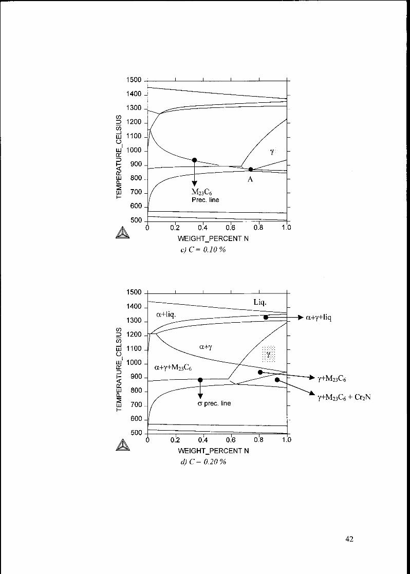
1500
1400
1300
r/i
3 1200
CO_l
UJ 1100u.
1UJ 1000ad-i
h- 900<rrLU 800Cl">
Hl /OO1-
600
500
A0.2 0.4 0.6 0.8
WEIGHT_PERCENT N
c)C= 0.10%
1.0
- a+y+liq
0.6 0.8 1.0
WEIGHT_PERCENT N
d)C= 0.20%
y+M23C6
y+M23C6 + Cr2N
42

6.3.1.2 YIELD STRENGTHAND ULTIMATE TENSILE STRENGTH
The yield strength and the ultimate tensile strength as function of the grain size are shown in a
Hall-Petch type diagram in Fig. 6-4.
EDC
.c+j
TOC0)l_
w
a
"55c0)
0 -I r1 H 1 1 1 1 1
0 2 4 6 8 10 12 14
(grain size D)"1'2 [mm"1/2]
Fig.6-4: effect of different carbon contents and grain sizes on tensile properties (continuous lines and
doted lines are the Hall-Petch type correlation for alloys with 0.20C and 0.10C 2Ni respectively).
With different cold working facilities and static recrystallization heat treatments, grain sizes
in the range 10-K200 um were achieved.
The elongation to fracture for all the alloys investigated was in the range 45-H50%.
Fig. 6-4 shows a difference in the level of strength between the alloy with lowest and highestcarbon content; this reduction in mechanical strength was most likely due to a reduction of the
solid solution hardening effect by carbon, as the nitrogen content was kept constant.
6.3.1.3 DUCTILE TO BRITTLE TRANSITION
Nitrogen and carbon are known to have a strong influence on the ductile to brittle transition
temperature (Tdbtt) in high nitrogen austenitic stainless steels [Miill94,Uggo92,Vogt94].For C + N > lwt% in solid solution the transition occurs at room temperature or above
[Uggo96].
Impact energy tests at different temperature, from -198°C to RT (25°C), were performed on
samples cut from the hot forged plates and annealed at 1050°C/lh in order to achieve fullyaustenitic microstructure.
The results are shown in Fig. 6-5, where the shape of the curves shown the typical "ductile to
brittle transition" behaviour of HNS, with a rapid decreasing in impact energy from high to
low values with decreasing the testing temperature.
1200
(C 1000CL
o"
a
800
600
TO
a> 400L.
+•»
(/>
2 2000)
3854^ti---CT"
~"a2*&$*- -S--
0.20C A0.17C
0.15C •0.14C
O0.12C1NÎ D0.10C2Ni
200Lim 50u,m 10lUTi
43
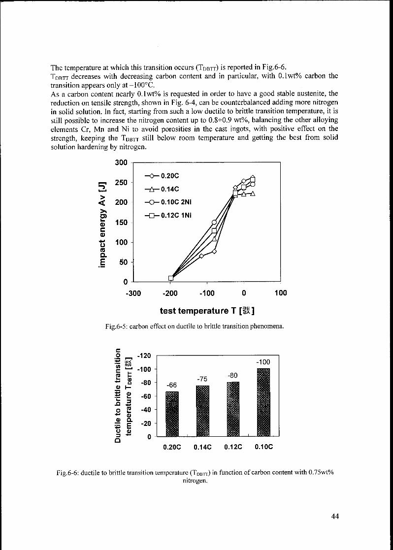
The temperature at which this transition occurs (Tdbtt) is reported in Fig.6-6.
Tdbtt decreases with decreasing carbon content and in particular, with 0.1wt% carbon the
transition appears only at -100°C.
As a carbon content nearly 0.1 wt% is requested in order to have a good stable austenite, the
reduction on tensile strength, shown in Fig. 6-4, can be counterbalanced adding more nitrogenin solid solution. In fact, starting from such a low ductile to brittle transition temperature, it is
still possible to increase the nitrogen content up to 0.8-0.9 wt%, balancing the other alloyingelements Cr, Mn and Ni to avoid porosities in the cast ingots, with positive effect on the
strength, keeping the Tdbtt still below room temperature and getting the best from solid
solution hardening by nitrogen.
300
Ï-. 250
200
150
>
<
>»TOi_
<DC
CD
t3 ioo
asa
E 50
-300 100-200 -100 0
test temperature T [UJ]
Fig.6-5: carbon effect on ductile to brittle transition phenomena,
0.20C 0.14C 0.12C 0.10C
Fig.6-6: ductile to brittle transition temperature (TDBtt) in function of carbon content with 0.75wt%
nitrogen.
44
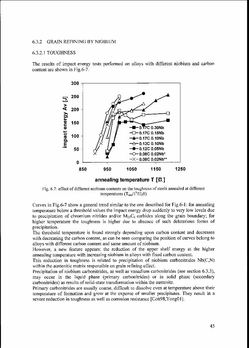
6.3.2 GRAIN REFINING BY NIOBIUM
6.3.2.1 TOUGHNESS
The results of impact energy tests performed on alloys with different niobium and carbon
content are shown in Fig.6-7.
850 950 1050 1150 1250
annealing temperature T [Ia]
Fig. 6.7: effect of different niobium contents on the toughness of steels annealed at different
temperatures (Tann/l'7H20)
Curves in Fig.6-7 show a general trend similar to the one described for Fig.6-1: for annealing
temperature below a threshold values the impact energy drop suddenly to very low levels due
to precipitation of chromium nitrides and/or M23C6 carbides along the grain boundary; for
higher temperature the toughness is higher due to absence of such deleterious forms of
precipitation.The threshold temperature is found strongly depending upon carbon content and decreases
with decreasing the carbon content, as can be seen comparing the position of curves belong to
alloys with different carbon content and same amount of niobium.
However, a new feature appears: the reduction of the upper shelf energy at the higher
annealing temperature with increasing niobium in alloys with fixed carbon content.
This reduction in toughness is related to precipitation of niobium carbonitrides Nb(C,N)within the austenitic matrix responsible on grain refining effect.
Precipitation of niobium carbonitrides, as well as vanadium carbonitrides (see section 6.3.3),
may occur in the liquid phase (primary carbonitrides) or in solid phase (secondary
carbonitrides) as results of solid-state transformation within the austenite.
Primary carbonitrides are usually coarse, difficult to dissolve even at temperature above their
temperature of formation and grow at the expense of smaller precipitates. They result in a
severe reduction in toughness as well as corrosion resistance [Cott98,Yong01].
45
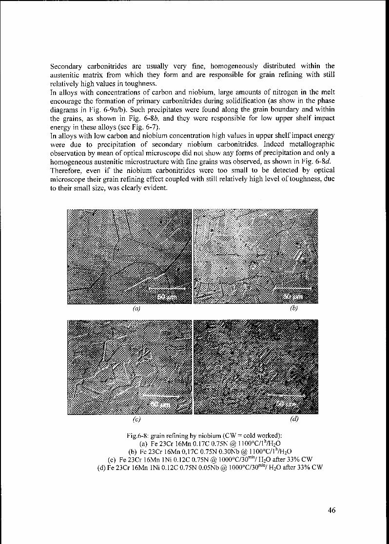
Secondary carbonitrides are usually very fine, homogeneously distributed within the
austenitic matrix from which they form and are responsible for grain refining with still
relatively high values in toughness.In alloys with concentrations of carbon and niobium, large amounts of nitrogen in the melt
encourage the formation of primary carbonitrides during solidification (as show in the phase
diagrams in Fig. 6-9a/b). Such precipitates were found along the grain boundary and within
the grains, as shown in Fig. 6-86, and they were responsible for low upper shelf impact
energy in these alloys (see Fig. 6-7).In alloys with low carbon and niobium concentration high values in upper shelf impact energy
were due to precipitation of secondary niobium carbonitrides. Indeed metallographicobservation by mean of optical microscope did not show any forms ofprecipitation and only a
homogeneous austenitic microstructure with fine grains was observed, as shown in Fig. 6-8d.
Therefore, even if the niobium carbonitrides were too small to be detected by optical
microscope their grain refining effect coupled with still relatively high level of toughness, due
to their small size, was clearly evident.
(a) (b)
Fig.6-8: grain refining by niobium (CW = cold worked):
(a) Fe 23Cr 16Mn 0.17C 0.75N @ 1100°C/lh/H2O(b) Fe 23Cr 16Mn 0,17C 0.75N 0.30Nb @ 1100°C/lh/H2O
(c) Fe 23Cr 16Mn INi 0.12C 0.75N @ 1000°C/30m,7 H20 after 33% CW
(d) Fe 23Cr 16Mn INi 0.12C 0.75N 0.05Nb @ 1000°C/30mi7 H20 after 33% CW
46
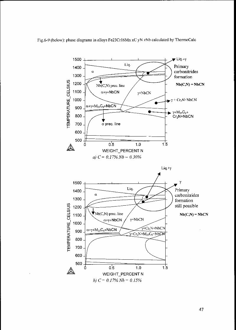
Fig.6-9 (below): phase diagrams in alloys Fe23Crl6Mn xC yN zNb calculated by ThermoCalc
1500
1400
1300
(D
D 12000)_l
III 1100
O.
LU 1000tt.—I
1- 900
rfUJ 8000.">
III /ooy-
600
500
A0.5 1.0
WEIGHT_PERCENT N
a)C= 0.17% Nb= 0.30%
Liq.+y
Primarycarbonitrides
formation
Nb(C,N) = NbCN
,y + Cr2N+NbCN
y+M23C6+Cr2N+NbCN
Liq.+y
0.5 1.0
WEIGHT_PERCENT N
b)C= 0.17%Nb= 0.15%
Primarycarbonitrides
formation
still possible
Nb(C,N) = NbCN
47

1500 J i i
1400 -
a
Y+NbCN+M23C6
Liq.Nb(C,N) = NbCN
1300-
<nz> 1200 _
w
LU 1100 -
O
lu1 1000 -
a:
H 900-
uj 800-a.
tu 700-r-
600-
"
< •— "W" ju14.~t7
a+Y /
/Y+NbCN ^^^~-
/ -^^^ Y+Cr2N ^ .1 pr \j i >,TUr,>1T
^^Y+Cr2N+M23C6
500 ^^~_^
A)
c)C =
0.5 1.0 1 .'5
WEIGHT_PERCENT N
0.12%M = 0.05% C+ M =7%)
Fig. 6-10 shown as in alloys containing niobium, grain refining was achieved during solution
annealing of samples directly cut from hot forged plates in comparison with alloys without
niobium.
300
250
TO
E 200
i
CDN
W
150
C
(5100
50 -
0
0.17C
0.17C 0.10Nb
0.17C 0.15Nb
0.17C 0.30Nb
950 1000 1050 1100 1150 1200 1250 1300
annealing temperature [1Ü]
Fig.6.10: grain size in hot forged and annealed alloys with/without niobium (Ta^/l 7H20).
48

In alloys containing niobium, the grain size as a function of the annealing temperature,remains more or less constant until the temperature for Nb(C,N) dissolution is reached. Above
this temperature fast grain growth, accelerated by the high temperature involved, takes place
resulting in bigger grain size.
On the contrary, the grain size of alloys without niobium were always found to increase with
increasing annealing temperature, as no obstacles for grain growth were present into the
austenitic matrix.
The temperature above which Nb(C,N) dissolution takes place were found to increase with
increasing Nb content (with same carbon content); in the alloy with less than 0.15wt% Nb
such a temperature was found between 1100+1200°C, whereas for 0.30wt% Nb it was above
1250°C, as small grains were still found at such a high temperature (60 urn).A comparison among curves in Fig. 6-1 and 6-7 belong to alloys with same carbon content,
show as niobium addition has the drawback to decrease the toughness at all the annealing
temperatures investigated in comparison with the same alloys without niobium. The
decreasing in toughness was severe for alloys with high carbon and high niobium contents
due to formation of primary carbonitrides, but moderate, hence tolerable, in alloy with low
niobium and low carbon where precipitation in the solid state of niobium carbonitrides
occurred.
6.3.2.2 YIELD STRENGTH AND ULTIMATE TENSILE STRENGTH
The yield strength and the ultimate tensile in function of the grain size are shown in a Hall-
Petch type diagram in Fig. 6-11.
E
1400
"cö"Q. 1200
o
a.TO ftCCD .ci_ +"»
*> TOCO c
o CDi_
^" +J
CO COc0 T3*-»
CD
>>
1000
800
600
400
200
A0.17C0.30Nb
D0.17C0.10Nb
X0.08C0.02Nb*
100|j,m 10|4.m
••-•'
O0.17C0.15Nb
• 0.12C0.05Nb
O0.08C0.02Nb**
3p.ni
10 15
1/2
20
-1/2!
25
(grain size D) [mm ]
Fig.6-11: effect of different niobium contents and grain sizes on tensile properties (continuous lines
and doted lines are the Hall-Petch type correlation for alloy with 0.17C 0.30Nb and 0.12C 0.05Nb
respectively; * = 0.83wt% N, ** = 0.87wt% N).
49

In spite of the big difference in toughness for alloys with different carbon and niobium
contents shown in Fig. 6-7, the grain size was in the range of 3^-100 u.m and does not show a
big difference for various niobium content.
The difference in yield strength and tensile strength in the alloys with 0.30wt% Nb, compare
with the one with 0.05wt% Nb, is most likely due to higher carbon content in the former one,
although a significant contribution by precipitation hardening from massive precipitation of
primary carbonitrides might be expected.
However, in the alloy with 0.05wt %Nb a yield strength and a tensile strength near 1 GPa and
1.2 GPa respectively have been achieved with a grain size of ~3um, after SRX at 900C/15min
made possible by the increased thermal stability of this alloy (see Fig. 6-12).
(c) (d)
Fig. 6-12: alloy Fe 23Cr 16Mn INi 0.75N 0.12C 0.05Nb after 33% cold working and SRX at
900°C/15mi" (a), 930°C/15min (b), 950°C/15mm (c) and 970°C/15min (d).
Grain sizes smaller than 3 um were expected after SRX heat treatment below 900°C on the
two most stable alloys (0.02wt% Nb and 0.08wt% C, see Fig. 6-7), instead it was not possible
to achieve grain sizes smaller than 6-7 urn (at 870°C/15mm): the amount of Nb(C,N)
precipitates was not enough to prevent excessive grain growth resulting in bigger grain size.
These investigations shown how in order to achieve a good combination of grain refining,hence mechanical strength, and toughness low carbon and low niobium content, around
0.1wt% and 0.05wt% respectively, are necessary.
50
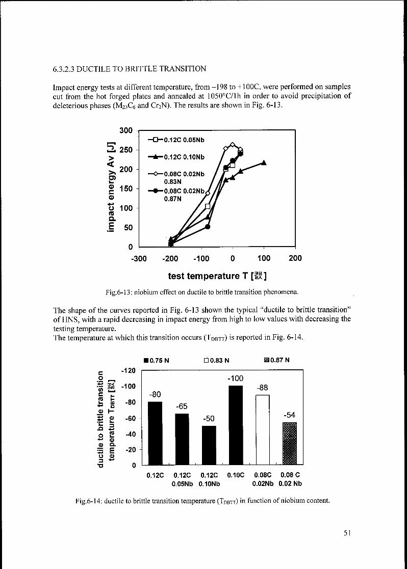
6.3.2.3 DUCTILE TO BRITTLE TRANSITION
Impact energy tests at different temperature, from -198 to +100C, were performed on samplescut from the hot forged plates and annealed at 1050°C/lh in order to avoid precipitation of
deleterious phases (M23C6 and Cr2N). The results are shown in Fig. 6-13.
300
200
2, 250
>
<
TO
g 150
CD
ü 100CO
a
E 50
-O-0.12C0.05Nb
-A-0.12C 0.1ONb 1 af
—0—0.08C 0.02Nb //O*^^0.83N Hi
-•-0.08C 0.02tibA/y0.87N /jj
-300 200-200 -100 0 100
test temperature T [Ix]
Fig.6-13: niobium effect on ductile to brittle transition phenomena.
The shape of the curves reported in Fig. 6-13 shown the typical "ductile to brittle transition"
of HNS, with a rapid decreasing in impact energy from high to low values with decreasing the
testing temperature.The temperature at which this transition occurs (Tdbtt) is reported in Fig. 6-14.
10.75 N D0.83N 10.87 N
-120
0.12C 0.12C 0.12C 0.10C 0.08C 0.08 C
0.05ND 0.10ND 0.02Nb 0.02 Nb
Fig.6-14: ductile to brittle transition temperature (TDBtt) in function of niobium content.
51
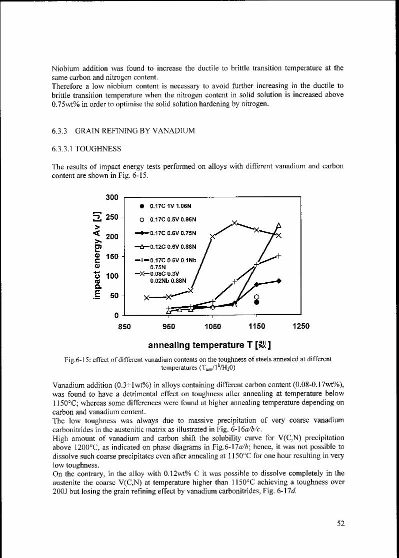
Niobium addition was found to increase the ductile to brittle transition temperature at the
same carbon and nitrogen content.
Therefore a low niobium content is necessary to avoid further increasing in the ductile to
brittle transition temperature when the nitrogen content in solid solution is increased above
0.75wt% in order to optimise the solid solution hardening by nitrogen.
6.3.3 GRAIN REFINING BY VANADIUM
6.3.3.1 TOUGHNESS
The results of impact energy tests performed on alloys with different vanadium and carbon
content are shown in Fig. 6-15.
300
"
250
>
<200
>TOi_
CD 150C
CD
o 100COQ.
E 50
• 0.17C1V1.06N
O 0.17C 0.5V 0.95N
-—0.17C 0.6V 0.75N
-Û-0.12C0.6V0.88N
—f—0.17C0.6V0.1Nb
0.75N
—X—0.08C 0.3V
0.02Nb 0.88N
X-
850 950 1050 1150 1250
annealing temperature T [131]
Fig.6-15: effect of different vanadium contents on the toughness of steels annealed at different
temperatures (Taim/lh/H20)
Vanadium addition (0.3-^lwt%) in alloys containing different carbon content (0.08-0.17wt%),was found to have a detrimental effect on toughness after annealing at temperature below
1150°C; whereas some differences were found at higher annealing temperature depending on
carbon and vanadium content.
The low toughness was always due to massive precipitation of very coarse vanadium
carbonitrides in the austenitic matrix as illustrated in Fig. 6-\6a/b/c.
High amount of vanadium and carbon shift the solubility curve for V(C,N) precipitationabove 1200°C, as indicated on phase diagrams in Fig.6-1 la/b; hence, it was not possible to
dissolve such coarse precipitates even after annealing at 1150°C for one hour resulting in very
low toughness.On the contrary, in the alloy with 0.12wt% C it was possible to dissolve completely in the
austenite the coarse V(C,N) at temperature higher than 1150°C achieving a toughness over
200J but losing the grain refining effect by vanadium carbonitrides, Fig. 6-17d.
52

The phase diagram of these alloys, Fig. 6-18c, shows that the solubility line for V(C,N)
precipitation is shifted towards low temperatures by less carbon content.
Therefore a carbon content lower than 0.12% together with a vanadium content lower than
0.5%) should give arise to precipitation of very fine vanadium carbonitrides, instead of coarse
ones, with not so detrimental effect on toughness.
Fig. 6-16: microstructure ofvanadium containing alloys:
(a) Fe 23Cr 16Mn 0.17C 0.5V 0.95N @ 1150°C/17H2O;
(b) Fe23Cr 16Mn0.17C IV 1.06N @1150°C/l'7H2O;(c) Fe23Crl6Mn0.12C0.6V0.88NlNi@ 1110°C/15mi7H2O;
(d) Fe23Crl6Mn0.12C0.6V0.88NlNi@ 1160°C/15m"VH2O.
6.3.3.2 YIELD STRENGTH AND ULTIMATE TENSILE STRENGTH
The dependence of the yield strength and ultimate tensile strength on the grain size is shown
in a Hall-Petch type diagram in Fig. 6-18.
53
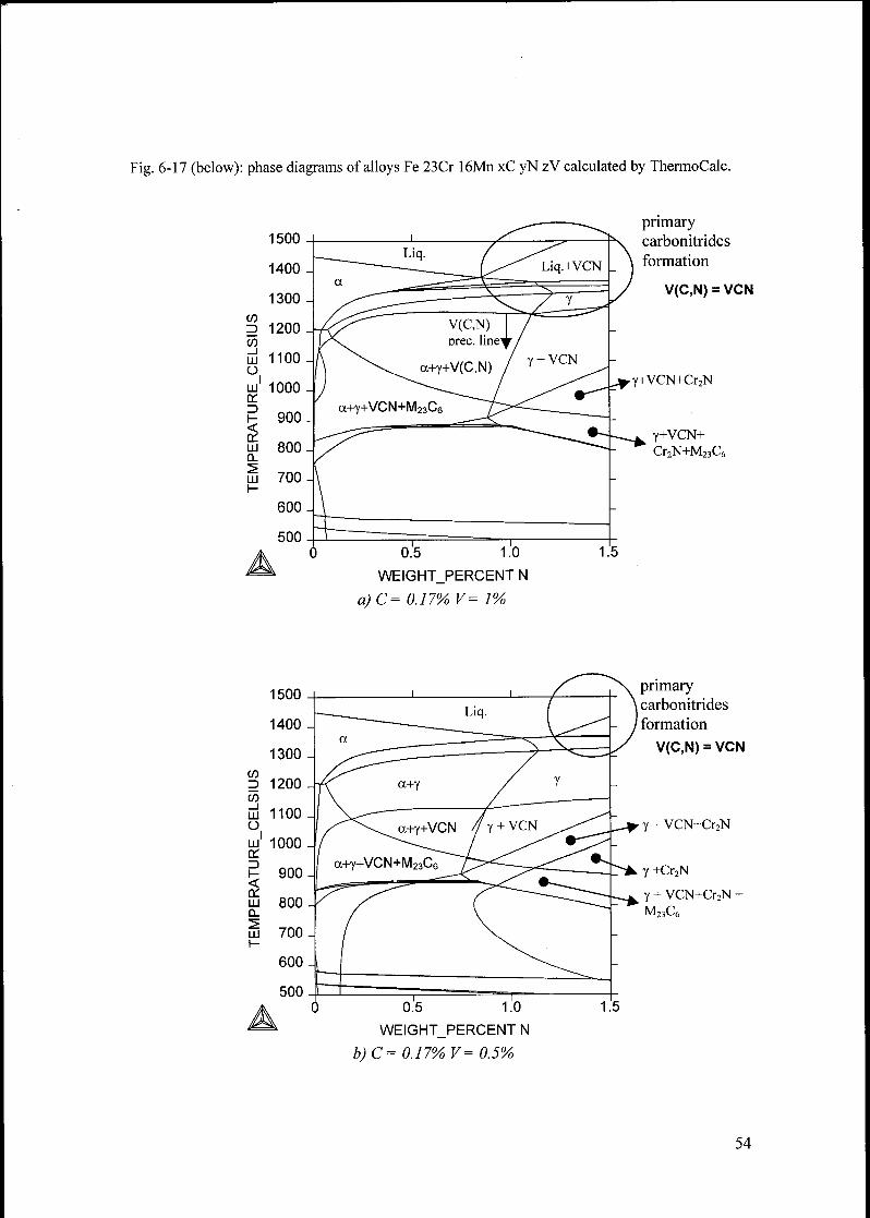
Fig. 6-17 (below): phase diagrams of alloys Fe 23Cr 16Mn xC yN zV calculated by ThermoCalc.
CO
=>
CO_i
UJü
IUJ
a:=>H
aLUÛ.
UJ
0.5 1.0
WEIGHT_PERCENT N
a)C= 0.17% V= 1%
primary
carbonitrides
formation
V(C,N) = VCN
,Y+VCN+Cr2N
Y+VCN+Cr2N+M23C6
1500
1400
1300
CO
co_i
UJ
O
1200
1100
UJ1a:=>h-
UJQ.
UJ
H
1000
900
800
700
600
500
A0.5 1.0
WEIGHT_PERCENT N
b)C= 0.17% V= 0.5%
primary
\ carbonitrides
' formation
V(C,N) = VCN
y + VCN+Cr2N
Y +Cr2N
Y + VCN+Cr2N +
M23C6
54
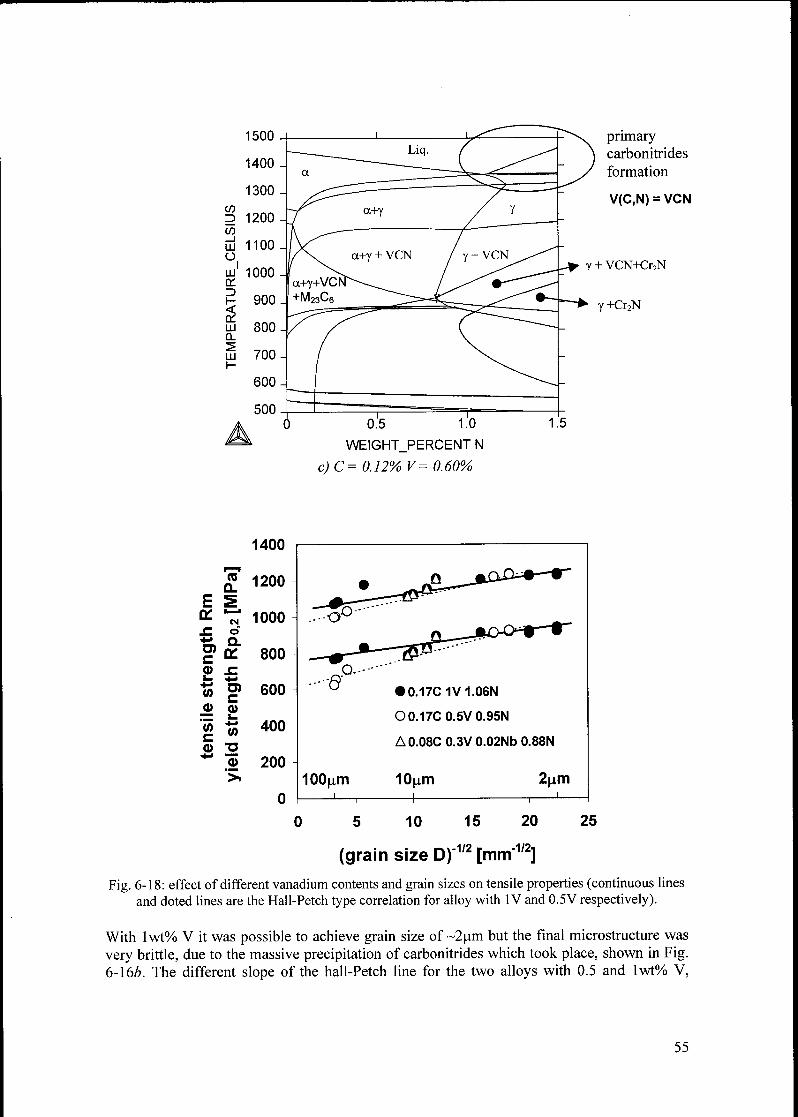
CO
=>
CO_l
UJ
oI
UJLX.
1-
èUJQ.
^UJI-
pnmary
carbonitrides
formation
V(C,N) = VCN
0.5 1.0
WEIGHT_PERCENT N
c)C= 0.12% V= 0.60%
CO
a.
E Sa: •—'
CM
JO o
+» nU)£
D*
CD .ci_ +j
COTOC
CD CDi_
COc
CO
CD T3*-> MB
CD
>
1400
1200
1000
800
600
400
200
0
• i&~~~mD^*r~*r
- .r^7"^
[^^•0.17C1V1.06N
O0.17C0.5V0.95N
A0.08C 0.3V 0.02Nb 0.88N
100p.m'—,
10p.m 2p.m—I 1 1—I—
5 10 15 20
(grain size D)"1/2 [mm"1'2]
25
Fig. 6-18: effect of different vanadium contents and grain sizes on tensile properties (continuous lines
and doted lines are the Hall-Petch type correlation for alloy with IV and 0.5V respectively).
With lwt% V it was possible to achieve grain size of ~2um but the final microstructure was
very brittle, due to the massive precipitation of carbonitrides which took place, shown in Fig.6-16Z». The different slope of the hall-Petch line for the two alloys with 0.5 and lwt% V,
55
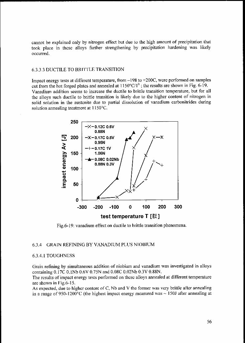
cannot be explained only by nitrogen effect but due to the high amount of precipitation that
took place in these alloys further strengthening by precipitation hardening was likelyoccurred.
6.3.3.3 DUCTILE TO BRITTLE TRANSITION
Impact energy tests at different temperature, from -198 to +200C, were performed on samples
cut from the hot forged plates and annealed at 1150°C/lh ; the results are shown in Fig. 6-19.
Vanadium addition seems to increase the ductile to brittle transition temperature, but for all
the alloys such ductile to brittle transition is likely due to the higher content of nitrogen in
solid solution in the austenite due to partial dissolution of vanadium carbonitrides duringsolution annealing treatment at 1150°C.
250
"
200
>
<>» 150TOi_
CDCCD 100+•
ÜCOQ.
E 50
-300 300
Fig.6-
200 -100 0 100 200
test temperature T [IÜ]
19: vanadium effect on ductile to brittle transition phenomena.
6.3.4 GRAIN REFINING BY VANADIUM PLUS NIOBIUM
6.3.4.1 TOUGHNESS
Grain refining by simultaneous addition of niobium and vanadium was investigated in alloys
containing 0.17C O.lNb 0.6V 0.75N and 0.08C 0.02Nb 0.3V 0.88N.
The results of impact energy tests performed on these alloys annealed at different temperature
are shown in Fig.6-15.As expected, due to higher content of C, Nb and V the former was very brittle after annealingin a range of 950-1200°C (the highest impact energy measured was ~ 150J after annealing at
56
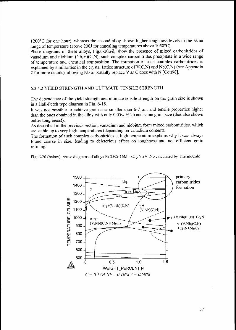
1200°C for one hour), whereas the second alloy shown higher toughness levels in the same
range of temperature (above 200J for annealing temperatures above 1050°C).Phase diagrams of these alloys, Fig.6-20a/2>, show the presence of mixed carbonitrides of
vanadium and niobium (Nb,V)(C,N); such complex carbonitrides precipitate in a wide range
of temperature and chemical composition. The formation of such complex carbonitrides is
explained by similarities in the crystal lattice structure of V(C,N) and Nb(C,N) (see Appendix2 for more details) allowing Nb to partially replace V as C does with N [Cott98].
6.3.4.2 YIELD STRENGTH AND ULTIMATE TENSILE STRENGTH
The dependence of the yield strength and ultimate tensile strength on the grain size is shown
in a Hall-Petch type diagram in Fig. 6-18.
It was not possible to achieve grain size smaller than 6-7 urn and tensile properties higherthan the ones obtained in the alloy with only 0.05wt%Nb and same grain size (that also shown
better toughness!).As described in the previous section, vanadium and niobium form mixed carbonitrides, which
are stable up to very high temperatures (depending on vanadium content).
The formation of such complex carbonitrides at high temperature explains why it was always
found coarse in size, leading to deleterious effect on toughness and not efficient grain
refining.
Fig. 6-20 (below): phase diagrams of alloys Fe 23Cr 16Mn xC yN zV tNb calculated by ThermoCalc
1500
1400
1300
CO3 1200
CO_l
UJ
o
1100
1LU
en3\-
$LUQ.
LUH
1000
900
800
700
600
500
A
primary
carbonitrides
formation
Y+(V,Nb)(C,N)+Cr2N
Y+(V,Nb)(C,N)
+Cr2N+M23C6
0.5 1.0
WEIGHT_PERCENT N
C= 0.17%Nb= 0.10% V= 0.60%
57
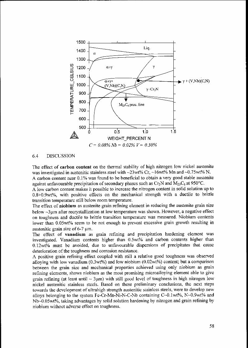
1500
1400
1300
CO3 1200
CO
Lu 1100O
lu1 1000en
?- 900
lu 800 4
Lu 700
600
500
Y + (V,Nb)(C,N)
0.5 1.0
WEIGHT_PERCENT N
C= 0.08%Nb = 0.02% V= 0.30%
6.4 DISCUSSION
The effect of carbon content on the thermal stability of high nitrogen low nickel austenite
was investigated in austenitic stainless steel with ~23wt% Cr, ~16wt% Mn and ~0.75wt% N.
A carbon content near 0.1% was found to be beneficial to obtain a very good stable austenite
against unfavourable precipitation of secondary phases such as Cr^N and M23C6 at 950°C.
A low carbon content makes it possible to increase the nitrogen content in solid solution up to
0.8-K).9wt%, with positive effects on the mechanical strength with a ductile to brittle
transition temperature still below room temperature.The effect of niobium as austenite grain refining element in reducing the austenite grain size
below ~3u.m after recrystallization at low temperature was shown. However, a negative effect
on toughness and ductile to brittle transition temperature was measured. Niobium contents
lower than 0.05wt% seem to be not enough to prevent excessive grain growth resulting in
austenitic grain size of 6-7 p.m.
The effect of vanadium as grain refining and precipitation hardening element was
investigated. Vanadium contents higher than 0.5wt% and carbon contents higher than
0.12wt% must be avoided, due to unfavourable dispersions of precipitates that cause
deterioration of the toughness and corrosion resistance.
A positive grain refining effect coupled with still a relative good toughness was observed
alloying with low vanadium (0.3wt%) and low niobium (0.02wt%) content; but a comparisonbetween the grain size and mechanical properties achieved using only niobium as grain
refining elements, shows niobium as the most promising microalloying element able to give
grain refining (at least until ~ 3pm) with still good level of toughness in high nitrogen low
nickel austenitic stainless steels. Based on these preliminary conclusions, the next steps
towards the development of ultrahigh strength austenitic stainless steels, were to develop new
alloys belonging to the system Fe-Cr-Mn-Ni-N-C-Nb containing C~0.1wt%, N~0.9wt% and
Nb~0.05wt%>, taking advantages by solid solution hardening by nitrogen and grain refining byniobium without adverse effect on toughness.
58
7. STRENGHTHENING MECHANISMS IN HIGH
NITROGEN AUSTENITIC STAINLESS STEELS
7.1 SCOPE
This chapter presents results concerning the role played by nitrogen on yield strength,ultimate tensile strength and ductility in steels strengthened by grain boundary hardening,dislocation hardening and precipitation hardening.Different strengthening mechanism were analysed singly and combined with the aim to
achieve an ultrahigh strength austenite containing nitrogen in solid solution as high as
possible, regardless of the adverse effect on the ductile to brittle transition.
Answers to the following questions were also searched:
Does there exist a practical limit for grain boundary hardening beyond which this
strengthening mechanism ceases to be applicable due to adverse effect on ductility in
steels?
How does this limit change with nitrogen?How can this limit be overcome in order to achieve a higher strength austenite?
Does grain refining have some influence on the ductile to brittle transition?
7.2 MATERIALS AND METHODS
By means of ThermoCalc, alloys were developed with nitrogen content up to 1.34wt% in
solid solution. The content of Cr, Mn and Ni was balanced in order to increases the nitrogen
solubility avoiding porosity during solidification in the ingots. Some alloys contain small
amount of niobium as further help to obtain small grains.The chemical composition ofthe alloys investigated is found in Tab.7-1 in Appendix 2.
All the alloys were cast into 3 Kg ingots, homogenized at 1240 °C for 8 hours and water
quenched, then hot forged at a temperature between 1100 and 1200°C to plates with a
thickness of 17 mm.
All alloys underwent a heat treatment at 1100°C/30mi7H20 before any further investigation in
order to bring back into solution eventual precipitates formed during the hot forging process
thus assuring a fully austenitic structure.
In order to achieve very small grains (smaller than 2-3 urn), static recrystallization heat
treatments were carried out on small samples heavily cold worked for short times, in the range
of one minute to fifteen minutes.
Cold deformation was performed by swaging round bars with an initial diameter of 15 mm
and a final one of 5 mm, for a degree of cold work of 89%.
59
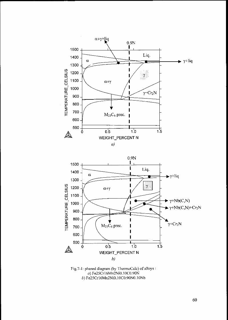
CO
3
CO_l
LU
oI
LUon3i-
onLUCL
LU
0.5 1.0
WEIGHT_PERCENT N
a)
Y+liq
co3
CO_l
LU
OI
LU
on3I-<onLUCL
LU
Fig.7-
y+liq
y+Nb(C,N)
y+Nb(C,N)+Cr2N
y+Cr2N
0.5 1.0
WEIGHT_PERCENT N
b)
1: phased diagram (by ThermoCalc) of alloys :
a) Fe25Crl6Mn2Ni0.10C0.90N
b) Fe25Crl6Mn2Ni0.10C0.90N0.10Nb
60
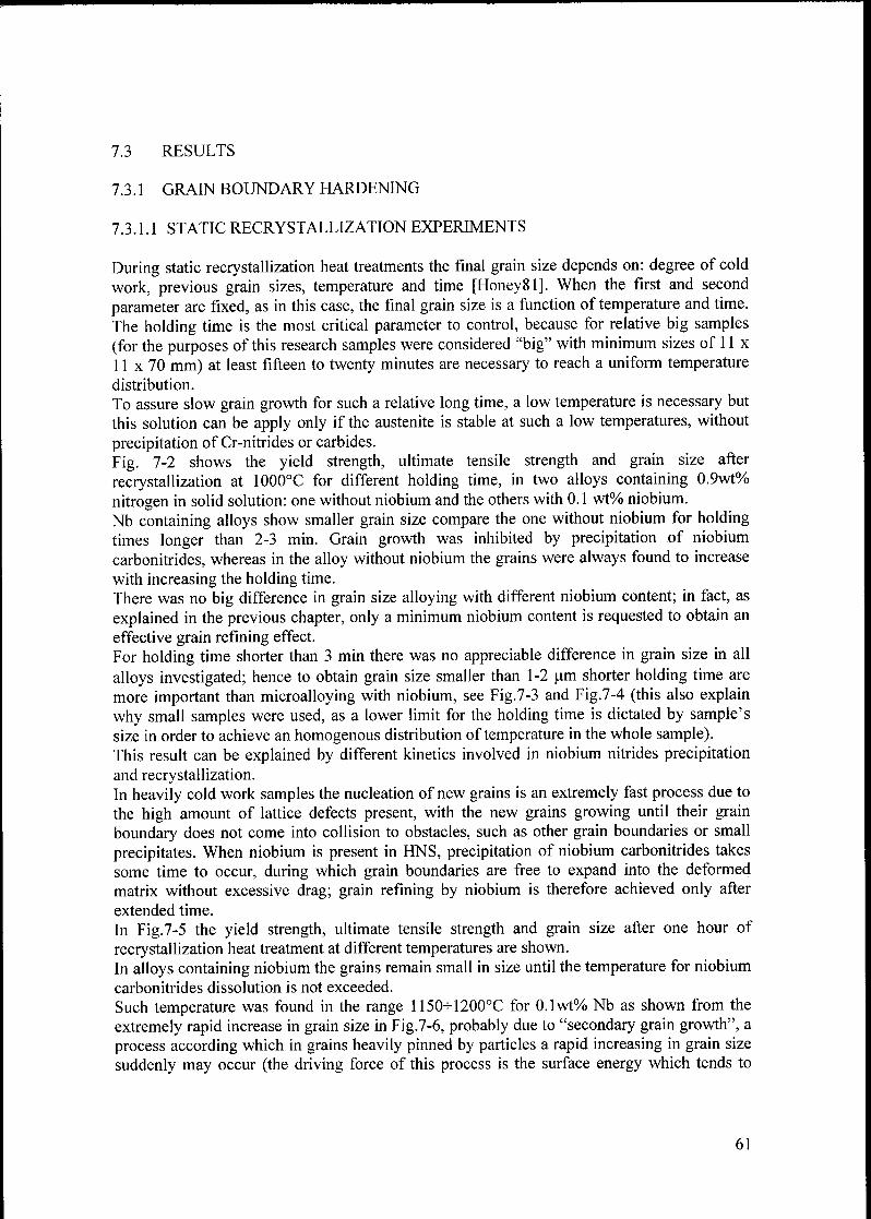
7.3 RESULTS
7.3.1 GRAIN BOUNDARY HARDENING
7.3.1.1 STATIC RECRYSTALLIZATION EXPERIMENTS
During static recrystallization heat treatments the final grain size depends on: degree of cold
work, previous grain sizes, temperature and time [Honey81]. When the first and second
parameter are fixed, as in this case, the final grain size is a function of temperature and time.
The holding time is the most critical parameter to control, because for relative big samples
(for the purposes of this research samples were considered "big" with minimum sizes of 11 x
11 x 70 mm) at least fifteen to twenty minutes are necessary to reach a uniform temperature
distribution.
To assure slow grain growth for such a relative long time, a low temperature is necessary but
this solution can be apply only if the austenite is stable at such a low temperatures, without
precipitation of Cr-nitrides or carbides.
Fig. 7-2 shows the yield strength, ultimate tensile strength and grain size after
recrystallization at 1000°C for different holding time, in two alloys containing 0.9wt%
nitrogen in solid solution: one without niobium and the others with 0.1 wt% niobium.
Nb containing alloys show smaller grain size compare the one without niobium for holding
times longer than 2-3 min. Grain growth was inhibited by precipitation of niobium
carbonitrides, whereas in the alloy without niobium the grains were always found to increase
with increasing the holding time.
There was no big difference in grain size alloying with different niobium content; in fact, as
explained in the previous chapter, only a minimum niobium content is requested to obtain an
effective grain refining effect.
For holding time shorter than 3 min there was no appreciable difference in grain size in all
alloys investigated; hence to obtain grain size smaller than 1-2 pm shorter holding time are
more important than microalloying with niobium, see Fig.7-3 and Fig.7-4 (this also explain
why small samples were used, as a lower limit for the holding time is dictated by sample'ssize in order to achieve an homogenous distribution of temperature in the whole sample).This result can be explained by different kinetics involved in niobium nitrides precipitationand recrystallization.In heavily cold work samples the nucleation of new grains is an extremely fast process due to
the high amount of lattice defects present, with the new grains growing until their grain
boundary does not come into collision to obstacles, such as other grain boundaries or small
precipitates. When niobium is present in HNS, precipitation of niobium carbonitrides takes
some time to occur, during which grain boundaries are free to expand into the deformed
matrix without excessive drag; grain refining by niobium is therefore achieved only after
extended time.
In Fig.7-5 the yield strength, ultimate tensile strength and grain size after one hour of
recrystallization heat treatment at different temperatures are shown.
In alloys containing niobium the grains remain small in size until the temperature for niobium
carbonitrides dissolution is not exceeded.
Such temperature was found in the range 1150h-1200°C for 0.1wt% Nb as shown from the
extremely rapid increase in grain size in Fig.7-6, probably due to "secondary grain growth", a
process according which in grains heavily pinned by particles a rapid increasing in grain size
suddenly may occur (the driving force of this process is the surface energy which tends to
61
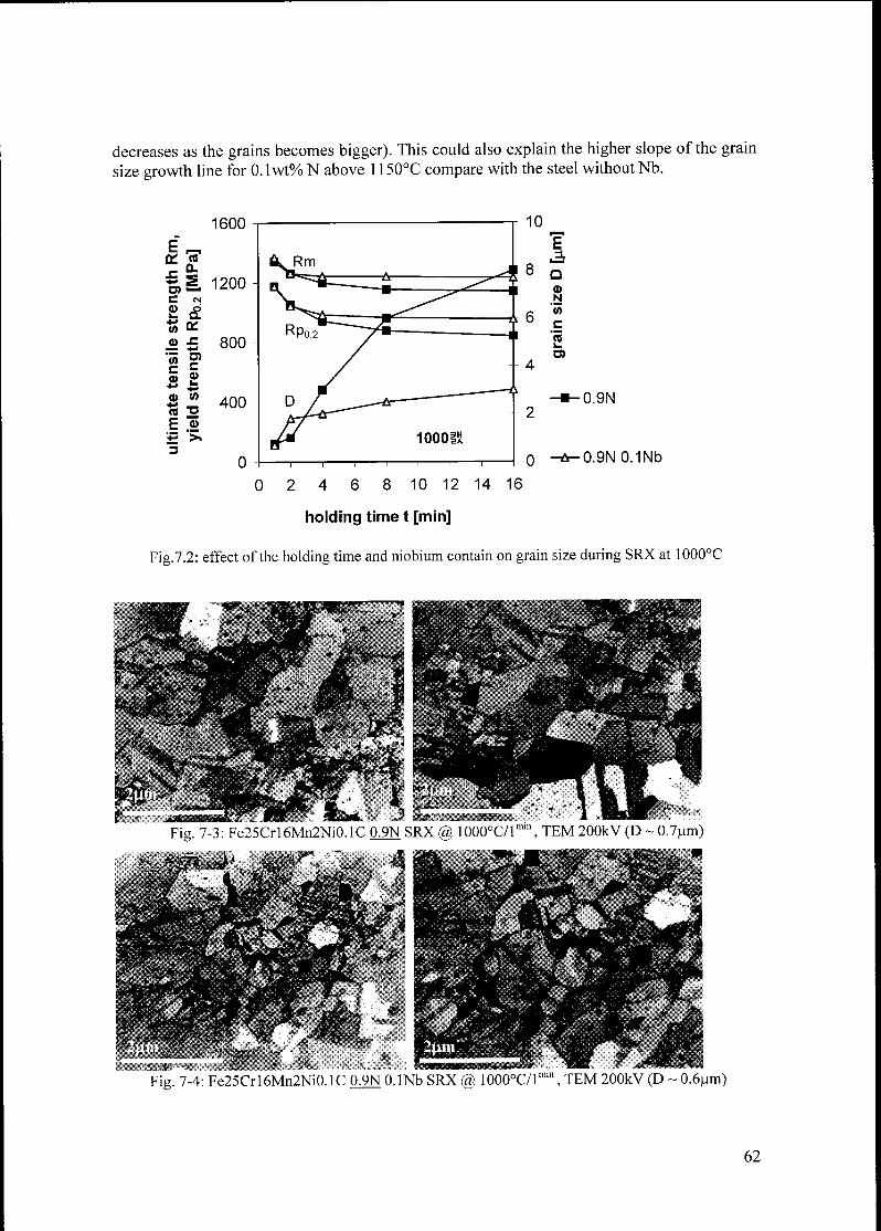
decreases as the grains becomes bigger). This could also explain the higher slope of the grain
size growth line for 0. lwt% N above 1150°C compare with the steel without Nb.
1600
E„
on n
il 1200
C CM
s &"55 on
ü £ 800
"55 ?c 5+* isO V)
(0 "O400
E «
S >«
3
0
0.9N
0.9N0.1Nb
0 2 4 6 8 10 12 14 16
holding time t [min]
Fig.7.2: effect of the holding time and niobium contain on grain size during SRX at 1000°C
Fig. 7-3: Fe25Crl6Mn2Ni0.1C 09N SRX @ 1000°C/lmm, TEM 200kV (D ~ 0.7um)
Fig. 7-4: Fe25Crl6Mn2Ni0.1C 09N O.lNb SRX @ 1000°C/lmm, TEM 200kV (D ~ 0.6pm)
62
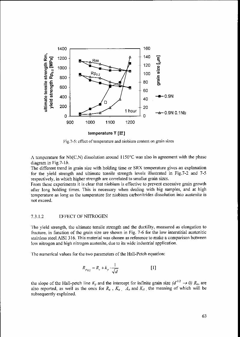
^
ItUU-
E ^K r?
1200 -
B^-^RrnB 2O) —' 1000
2 t£ H^RPo2t» * 800
o ^=— *j
C T.600
nate elds400 -
JOy
.= >> 200_
3
0- 1 1
1 hour
160
140
120
100
80
60
40
20
0
E
oN
"S>C
s
0.9N
0.9N 0.1Nb
900 1000 1100 1200
temperature T [UJ]
Fig.7-5: effect of temperature and niobium content on grain sizes
A temperature for Nb(C,N) dissolution around 1150°C was also in agreement with the phase
diagram in Fig.7-lè.The different trend in grain size with holding time or SRX temperature gives an explanationfor the yield strength and ultimate tensile strength levels illustrated in Fig.7-2 and 7-5
respectively, in which higher strength are correlated to smaller grain sizes.
From these experiments it is clear that niobium is effective to prevent excessive grain growthafter long holding times. This is necessary when dealing with big samples, and at high
temperature as long as the temperature for niobium carbonitrides dissolution into austenite is
not exceed.
7.3.1.2 EFFECT OF NITROGEN
The yield strength, the ultimate tensile strength and the ductility, measured as elongation to
fracture, in function of the grain size are shown in Fig. 7-6 for the low interstitial austenitic
stainless steel AISI 316. This material was chosen as reference to make a comparison between
low nitrogen and high nitrogen austenite, due to its wide industrial application.
The numerical values for the two parameters of the Hall-Petch equation:
RP02=Ro+ky- 4d[1]
rl/2the slope of the Hall-petch line Ky and the intercept for infinite grain size (d
"
—> 0) R0, are
also reported, as well as the ones for Ru , Ku_
A0 and Ka,
the meaning of which will be
subsequently explained.
63
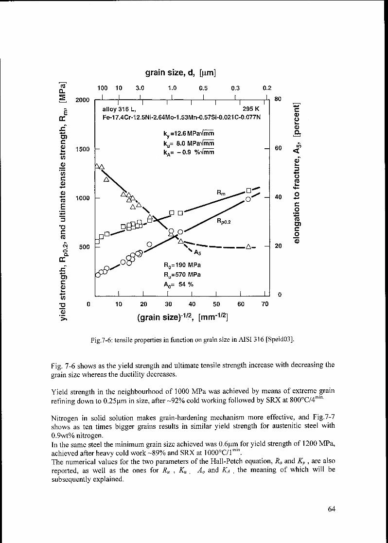
grain size, d, [|nm]
(0
Û_
!=, 2000
EC
CQik.
CO
_ÇU"wceu
eu+-
ca
E
o
c
to
cic>a.
Œ
JC
O)c
CDk.
co
eu
100 10 3.0 1.0 0.5 0.3 0.2
1500
V>
1000
500
I I I I I I
alloy 316 L, 295 K
Fe-17.4CM 2.5Ni-2.64Mo-1.53Mn-0.57Si-0.021 C-0.077N
k,,=12.6MPaVrnm
DD.
ku= 8.0 MPaVmrn
kA= -0.9 %Vmm
AA.
ôv-DD
68'O
Q'A.
As-A- -
R0=190 MPa
Ru=570 MPa
An= 54%
80
60
Cd)
Ok_
0)
a
<
Ok.
3
U03
40 Ü
C
.2
eu
D)C
o
0)20
10 20 30 40 50 60 70
(grain size)-172, [mnr1/2]
Fig.7-6: tensile properties in function on grain size in AISI 316 [Speid03].
Fig. 7-6 shows as the yield strength and ultimate tensile strength increase with decreasing the
grain size whereas the ductility decreases.
Yield strength in the neighbourhood of 1000 MPa was achieved by means of extreme grain
refining down to 0.25pm in size, after -92% cold working followed by SRX at 800°C/4min
Nitrogen in solid solution makes grain-hardening mechanism more effective, and Fig.7-7
shows as ten times bigger grains results in similar yield strength for austenitic steel with
0.9wt% nitrogen.In the same steel the minimum grain size achieved was 0.6pm for yield strength of 1200 MPa,
achieved after heavy cold work -89% and SRX at 1000°C/lmin.
The numerical values for the two parameters of the Hall-Petch equation, R0 and Ky ,are also
reported, as well as the ones for Ru ,Ku
;
A0 and KA,
the meaning of which will be
subsequently explained.
64
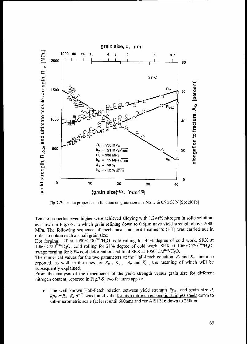
ce
a
ce
o4-«
ra
E
c
co
cida
ca>
+•
co
33o
grain size, d, [jim]
1000 100 20 10 4 3 2 1
2000 J ' 1 1 L
C
£ 1500
co
a>
'coc
a>
1000
500
JöboO
R0 = 530 MPa
ky = 21 MPavmm
Ru = 930 MPa
ku = 15 MPaVmrn
Ao = 60 %
kA =-1.2%A/rnm
"Ni20
_L J_
40
C0)Ük.
O)Q.
10
<
k.
3*-•
ÜCO
C
o
coO)c
o
CD
0 10 20 30
(grain size)-"«« [mm-1/2]
Fig.7-7: tensile properties in function on grain size in FINS with 0.9wt% N [SpeidOlb]
Tensile properties even higher were achieved alloying with 1.2wt% nitrogen in solid solution,
as shown in Fig.7-8, in which grain refining down to 0.6pm gave yield strength above 2000
MPa. The following sequence of mechanical and heat treatments (HT) was carried out in
order to obtain such a small grain size:
Hot forging, HT at 1050°C/30min/H2O, cold rolling for 44% degree of cold work, SRX at
1060°C/20mi7H2O, cold rolling for 21% degree of cold work, SRX at 1060°C/20mi7H2O,
swage forging for 89% cold deformation and final SRX at 1050°C/2mi7H2O.
The numerical values for the two parameters of the Hall-Petch equation, R0 and Ky ,are also
reported, as well as the ones for Ru , Ku,
A0 and KA,
the meaning of which will be
subsequently explained.From the analysis of the dependence of the yield strength versus grain size for different
nitrogen content, reported in Fig.7-9, two features appear:
• The well known Hall-Petch relation between yield strength Rpo.2 and grain size d,
Rpo2=Ro+K/d1/2, was found valid for high nitrogen austenitic stainless steels down to
sub-micrometric scale (at least until 600nm) and for AISI 316 down to 250nm;
65
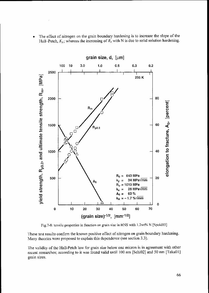
The effect of nitrogen on the grain boundary hardening is to increase the slope of the
Hall-Petch, Ky; whereas the increasing of R0 with N is due to solid solution hardening.
CO
Q_
CC
s£+>
cok_
+>
CO
0)
'55c
CD
CD+-<
CO
E
cCO
da.
CE
CCDk_
+-•
CO
3?CD
100 10
grain size, d, [|im]
3.0 1.0 0.5 0.3 0.2
2500
2000
1500
1000
500
T n
295 K
- 80
R0 = 640 MPa
ky = 34 MPaVmm
Ru =1010 MPa
ku = 28 MPaVmrn
A0 = 60 %
kA = - 1.7 %Vmm
60
c
CDOk.
CDa
in
<
k.
3*-•
O(0
40 ac
O
(O
£
o
20
10 20 30 40 50 60 70
(grain size)-172, [mnrr1/2]
Fig.7-8: tensile properties in function on grain size in HNS with 1.2wt% N [Speid03]
These test results confirm the known positive effect of nitrogen on grain boundary hardening.
Many theories were proposed to explain this dependence (see section 3.3).
The validity of the Hall-Petch law for grain size below one micron is in agreement with other
recent researches; according to it was found valid until 100 nm [Schi02] and 50 nm [TakaOl]
grain sizes.
66

grain size, d, [fxm]
100 10 3.0
2500
2000
COCL
Ä 1500
öQ.
ce
C
Iw
3215"5»
1000
1.0
_l_
0.5 0.3 0.2
effect of grain size on yield strength
austenitic stainless steels, 295 K
/1.2%N»30Cr
0.9%N, 23Cr
500
10 20 30 40 50 60
(grain size)-172, [mm-172]
70
Fig. 7-9: yield strength versus grain size for different nitrogen content
From the analysis of Fig.7-6, 7-7 and 7-8, a relation similar to the Hall-Petch equation was
found to exist between ultimate tensile strength Rm and grain sizes as well as elongation to
fracture A5 and grain size, for all the range ofgrain size investigated.Such new relations have been established by Speidel [SpeodOlb, Speid02, Speid03]
A5=A0+kA.-j=
[2]
[3]
67
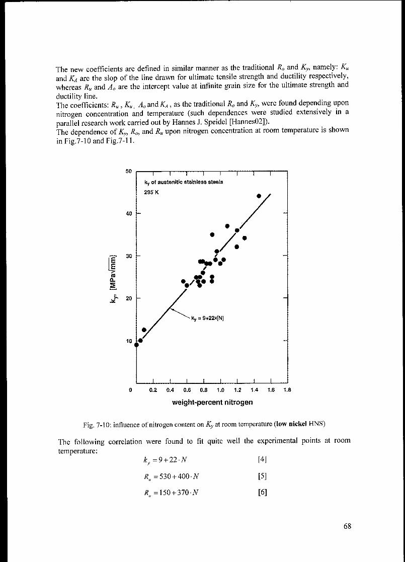
The new coefficients are defined in similar manner as the traditional R0 and Ky, namely: Ku
and KA are the slop of the line drawn for ultimate tensile strength and ductility respectively,
whereas Ru and A0 are the intercept value at infinite grain size for the ultimate strength and
ductility line.
The coefficients: Ru , Ku, A0andKA, as the traditional R0 and Ky, were found depending upon
nitrogen concentration and temperature (such dependences were studied extensively in a
parallel research work carried out by Hannes J. Speidel [Hannes02]).
The dependence of Ky, R0, and Ru upon nitrogen concentration at room temperature is shown
inFig.7-10andFig.7-ll.
50
40
30 -
E
Jro
Q.
s
J* 20
10
ky of austenitic stainless steels
295 K
•/••
vt# *
ky a 9+22x[NJ
X ä
0 0.2 0.4 0.6 0.8 1.0 1.2 1.4 1.6 1.8
weight-percent nitrogen
Fig. 7-10: influence of nitrogen content on Ky at room temperature (low nickel HNS)
The following correlation were found to fit quite well the experimental points at room
temperature:
ky=9 + 22-N
i?„=530 + 400-#
it" = 150 + 370-JV
[4]
[5]
[6]
68

03 1200
1100
1000
ö)cCD 900k.4m<
(0
CD 800
CO
£CD 700
Ü*-.
CO600
*->
3500
"UC
co
s 400
cer.
SZ 300UicCDk. 200
CO
T3
CD 100
>.
j ! ( j (
R0 and RU) austenitic stainless steel
295 K
Ro = 150+370x[N|
RP0.2 = Ro+ky'd"",ßRm - Rü+ku.d-1ß
X
0 0.2 0.4 0.6 0.8 1,0 1.2 1.4 1.6 1.8
weight-percent nitrogen
Fig. 7-11 : influence of nitrogen content on R0 and Ru at room temperature
The relations [1], [2] and [3], show as yield strength and ultimate tensile strength increase
with decreasing the grain size, whereas the ductility, measured as elongation to fracture,
decreases.
Therefore, if grain boundary hardening helps to increase the mechanical strength it has as
main drawback a decreasing in ductility that can drop to very low values for extreme grain
refining coupled with very high nitrogen content, as shown in Fig. 7-8.
This may represent a practical limit for grain boundary hardening, if a certain level of
ductility has to be maintained.
At the moment the relationship between grain size and ductility, as well as the one between
ultimate tensile strength and grain size, cannot be explained by currently available theories
69

about grain boundary hardening in high nitrogen austenitic stainless steel, hence should be
"taken" as an experimental fact.
Actually, the situation does not become better even when considering the effect of nitrogen on
the more traditional Hall-Petch equation, which is described in different ways/models but no
general consent has been established to identify the correct theory among the HNS specialists
yet!
7.3.2 DISLOCATION HARDENING AND PRECIPITATION HARDENING
High nitrogen austenitic stainless steels, which have already a high yield strength due to solid
solution hardening and due to fine grain hardening, can be further strengthened by cold
working and subsequent strain ageing.This is illustrated in Fig. 7-12, 7-13, 7-14 and 7-15 where the yield strength, the ultimate
tensile strength and the elongation to fracture for alloys with different nitrogen content are
plotted in function of degree of cold work.
These pictures show that the effect of cold work on increasing both yield strength and
ultimate tensile strength is much higher for HNS than for low interstitial austenite such as
type 316.
Nitrogen increases the strain hardening rate achieving higher level of strength with the same
degree of cold work; the reason of such effect is related to profound influence of nitrogen on
plastic deformation in austenite, as described in details in section 3.2.
F r—^
on ra
Q.sz SD)
^J
c CM
atk. Q.
(A on
4) sz+J
il) o
C c
0)
4->
0) in
w o
E*3
3
2000
1600
1200
m
<
<U
30 =
ore
D)m
co
0)
0 20 40 60 80
degree of cold work [%]
100
Fig.7-12: effects of dislocation hardening on yield strength, ultimate tensile strength and ductility in
low interstitial austenitic stainless steels (AISI 316 N<0.01wt%)
70

F ,_,
onQ.
sz 2
O)-,
c
a>k. (1.
(0 et
o .c*»
(/> O)
c: c
a>k.4-*
o (0
co o
F u
'3 >.
3
3000
2500
= 2000
1500
1000
500
20 40 60 80
degree of cold work [%]
100
Fig.7-13: effects of dislocation hardening on yield strength, ultimate tensile strength and ductility in
high nitrogen austenitic stainless steels (N ~ 0.9 wt%)
3000
F 2500
on TO
Q.sz 5
C
immê
CM 2000
0)k. Q.
c/> on
Qi sz 1500+J
vi O)
r c
o*••
0)k>
1000a> in<->
a
E a>
+* >. 5003
0
0 20 40 60 80 100
degree of cold work [%]
Fig.7-14: effects of dislocation hardening on yield strength, ultimate tensile strength and ductility in
high nitrogen austenitic stainless steels (N ~ 1.2 wt%)
71
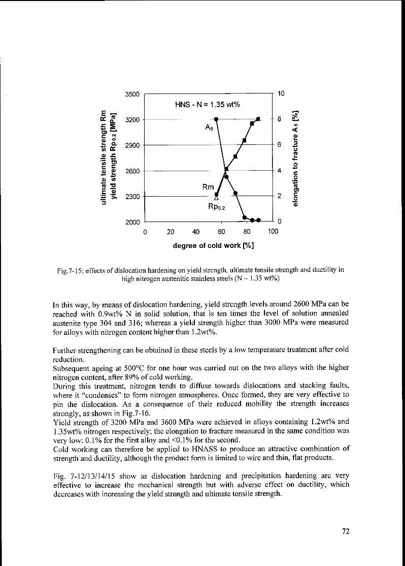
e
onQ.
sz SO)
l_4
c CM
0)O
k. Q.
in on
<o sz+J
vt TO
c C
(1) 9>+-I
+J
0) M
TO ^O
F <D
^3 >.
3
3500
3200
2900
2600
2300
2000
<
23
U
C
o
10
TOC
o
20 40 60 80 100
degree of cold work [%]
Fig.7-15: effects of dislocation hardening on yield strength, ultimate tensile strength and ductility in
high nitrogen austenitic stainless steels (N ~ 1.35 wt%)
In this way, by means of dislocation hardening, yield strength levels around 2600 MPa can be
reached with 0.9wt% N in solid solution, that is ten times the level of solution annealed
austenite type 304 and 316; whereas a yield strength higher than 3000 MPa were measured
for alloys with nitrogen content higher than 1.2wt%.
Further strengthening can be obtained in these steels by a low temperature treatment after cold
reduction.
Subsequent ageing at 500°C for one hour was carried out on the two alloys with the higher
nitrogen content, after 89% of cold working.
During this treatment, nitrogen tends to diffuse towards dislocations and stacking faults,
where it "condenses" to form nitrogen atmospheres. Once formed, they are very effective to
pin the dislocation. As a consequence of their reduced mobility the strength increases
strongly, as shown in Fig.7-16.Yield strength of 3200 MPa and 3600 MPa were achieved in alloys containing 1.2wt% and
1.35wt% nitrogen respectively; the elongation to fracture measured in the same condition was
very low: 0.1%) for the first alloy and <0.1% for the second.
Cold working can therefore be applied to HNASS to produce an attractive combination of
strength and ductility, although the product form is limited to wire and thin, flat products.
Fig. 7-12/13/14/15 show as dislocation hardening and precipitation hardening are very
effective to increase the mechanical strength but with adverse effect on ductility, which
decreases with increasing the yield strength and ultimate tensile strength.
72

The same trend between strength and ductility was also found for grain boundary hardening,
as described at the end of the previous section.
degree of cold working [%]
Fig. 7-16: ultimate tensile strength as a function of dislocation hardening and precipitation hardening
(static strain ageing) in HNS with different nitrogen content
One of the most remarkable developments concerning HNS has always been the attainment of
higher and higher yields strength level by judicious combination of all four basic hardeningmechanisms.
The result of this strategy is summarized in Fig.7-17, which shows a sort of "historical trend"
in the development of ultrahigh strength high nitrogen austenitic stainless.
In a fully austenitic microstructure free of any kind of precipitates (even martensite) yield
strength of 2000 MPa in annealed condition and 3600 MPa in cold work and strain ageingcondition were achieved during this Ph.D. work.
These values represent so far a new record in strength for HNS!
In Fig. 7-17 the former record is also shown, as a point at 3400 MPa of yield strength reached
in 1991 [Uggo91].
This level of strength was achieved in wires; heavily cold draw with a final diameter less than
lmm and the material was HNS produced by pressure metallurgy.
Therefore, another outstanding result is that the new record in strength was achieved in bulk
material (sample with a diameter of 5 mm) made without overpressure with traditional ingot
metallurgy as results of alloy development strategy.
73

4000
CO
Q.
CN
dQ.
LT
3000
2000
D)C
Ok-
+-•
co
33(D
>, 1000
T
yield strength of
stable austenitic steels
• high nitrogen steels, bulk
made without overpressure
( )
I
1250
cold worked v
\/
(•)
t
/I
/o-
1912
/ 600 y %S I• solution annealed v ^ä^ I
(Type 316)
1900 1920 1940 1960 1980 2000
year of introduction
Fig.7-17: historical trend in the development of ultrahigh strength HNS
7.3.3 STRENGTH AND DUCTILITY COMBINED
Strength alone, as resistance to plastic deformation, and ductility can be quite high in separate
materials, however for structural materials a balanced combination of both is necessary.
Common criteria used by metallurgist for the evaluation of engineering materials is the
combination of yield strength and ductility; main objective of alloy development, used for
structural materials, is to increase both properties at the same time.
Fig. 7-18 and Fig. 7-19 show yield strength (Rp02) and ultimate tensile strength (Rm) versus
ductility, measured as elongation to fracture (A5), in alloys with different nitrogen content in
solid solution.
For every nitrogen content, the experimental points representative of different combination
(Rp02 - A5) or (Rm - A5), obtained using different strengthening mechanisms, were found to fit
quite well on a same curve.
The curves differ in the strength-ductility plane because of their nitrogen content in solid
solution.
74
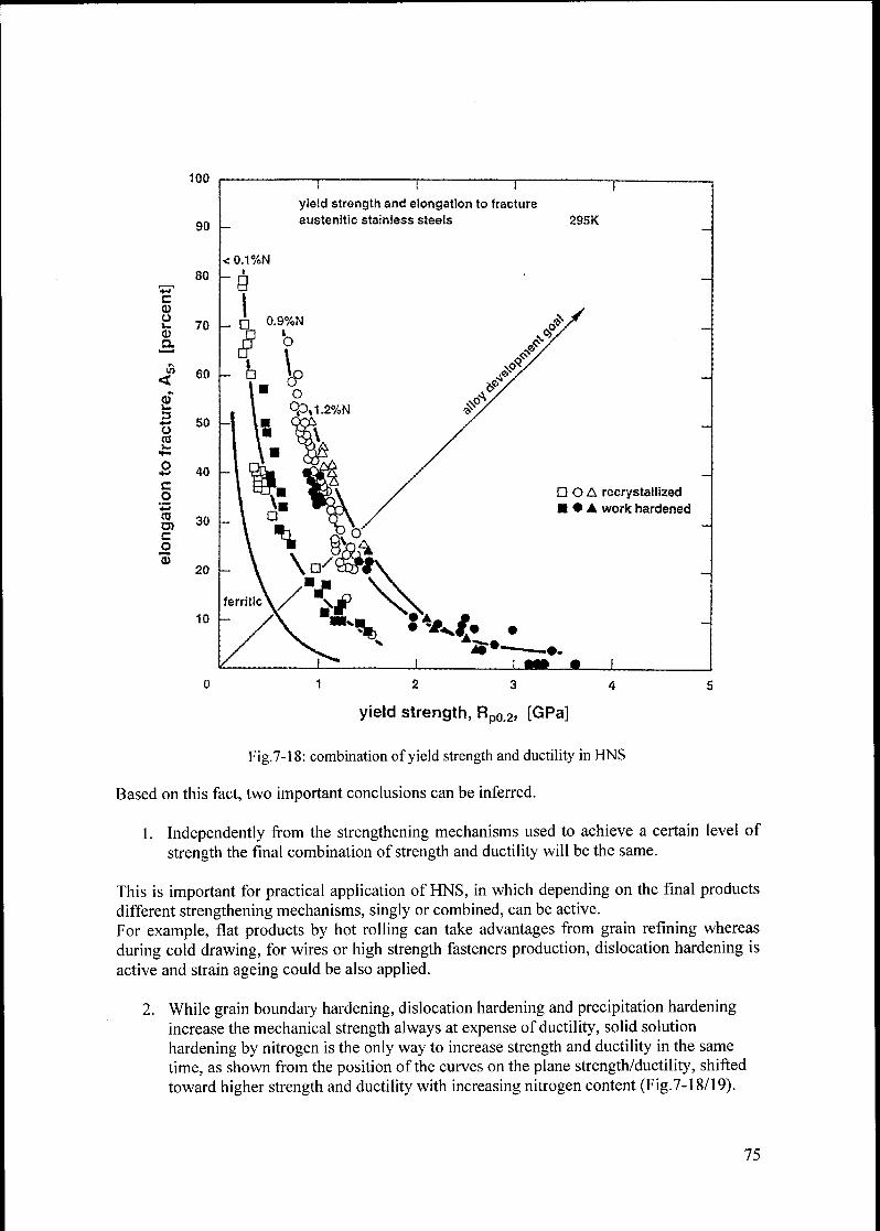
100
90
80
Ceu"
70<D
60<
i3*s 50
co
Ü 40
CO
coo>c
o
"S
30
20
10
I I I ^
yield strength and elongation to fracture
austenitic stainless steels 295K
D O A recrystallized• A work hardened
m l
0 12 3 4 5
yield strength, Rp0.2» [GPa]
Fig.7-18: combination of yield strength and ductility in HNS
Based on this fact, two important conclusions can be inferred.
1. Independently from the strengthening mechanisms used to achieve a certain level of
strength the final combination of strength and ductility will be the same.
This is important for practical application of HNS, in which depending on the final productsdifferent strengthening mechanisms, singly or combined, can be active.
For example, flat products by hot rolling can take advantages from grain refining whereas
during cold drawing, for wires or high strength fasteners production, dislocation hardening is
active and strain ageing could be also applied.
2. While grain boundary hardening, dislocation hardening and precipitation hardening
increase the mechanical strength always at expense of ductility, solid solution
hardening by nitrogen is the only way to increase strength and ductility in the same
time, as shown from the position of the curves on the plane strength/ductility, shifted
toward higher strength and ductility with increasing nitrogen content (Fig.7-18/19).
75
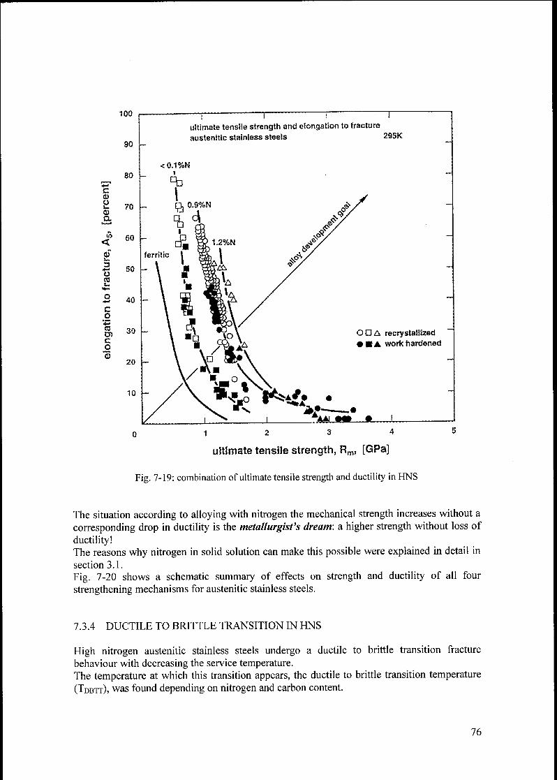
100
90 -
Ca>
ok.
0)Cl¬
io
<
i3*-*
OCO
c
o
coO)
o
o
I i I I
ultimate tensile strength and elongation to fracture
austenitic stainless steels 295K
OÖA recrystallized
• A work hardened
—
0 12 3 4
ultimate tensile strength, Rm, [GPa]
Fig. 7-19: combination ofultimate tensile strength and ductility in HNS
The situation according to alloying with nitrogen the mechanical strength increases without a
corresponding drop in ductility is the metallurgist's dream: a higher strength without loss of
ductility!The reasons why nitrogen in solid solution can make this possible were explained in detail in
section 3.1.
Fig. 7-20 shows a schematic summary of effects on strength and ductility of all four
strengthening mechanisms for austenitic stainless steels.
7.3.4 DUCTILE TO BRITTLE TRANSITION IN HNS
High nitrogen austenitic stainless steels undergo a ductile to brittle transition fracture
behaviour with decreasing the service temperature.
The temperature at which this transition appears, the ductile to brittle transition temperature
(Tdbtt), was found depending on nitrogen and carbon content.
76

c
o
0>
<
es)
3
Üco
c
.2^3CO
D)Co
100
90
80
70
60
50
40
30
20
10
! ^.
j j
strength and ductility of stainless steels (schematic)all four hardening mechanisms * solid solution hardening
• fine grain hardening• work hardening• ageing
0 12 3 4
strength, [GPa]
Fig.7-20: effect on strength and ductility of different strengthening mechanisms
Results described in Chapter 5 show how such a transition temperature was also found to
depend on other alloying elements, namely niobium and vanadium.
In order to clarify the role of different alloying element on Tdbtt a regression analysis using
the last squares method was carried out on many different kind of high nitrogen austenitic
stainless steels, some of them developed during this work and other taken from different
sources (literature and previous Ph.D works at the Institute of Metallurgy ETZ-Zurich).
A collection of results for different alloys is shown in Fig. 7-21, where the real Tdbtt, as
measured by impact energy tests carried out at different testing temperature, is compared with
the one calculated by means of the following formulas:
-dbtt 300-N+100-C
Tdbtt = 300-N + 100-C - 20-(Ni + Cu)
[11]
[12]
77
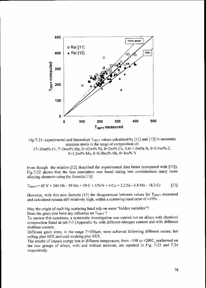
0 100 200 300 400 500
Tdbtt measured
Fig-7-21 : experimental and theoretical TDbtt values calculated by [11] and [12] in austenitic
stainless steels in the range of composition of:
17-30wt% Cr, 7-26wt% Mn, 0-42wt% Ni, 0-2wt% Cu, 0.6-1.4wt% N, 0+0.3wt% C,
0-3.2wt% Mo, 0-0.30wt% Nb, 0+1tw% V
Even though the relation [12] described the experimental data better (compared with [11]),
Fig.7-22 shows that the best correlation was found taking into consideration many more
alloying elements using the formula [13]:
TDbtt= 45-V + 305-Nb - 19-Mo + 59C + 576-N + 6-Cu + 2.2-Ni - 6.8-Mn - 18.2-Cr [13]
However, with this new formula [13] the disagreement between values for Tdbtt measured
and calculated remain still relatively high, within a scattering band error of ±10%.
May the origin of such big scattering band rely on some "hidden variables"?
Does the grain size have any influence on Tdbtt ?
To answer this questions, a systematic investigation was carried out on alloys with chemical
composition listed in tab.7-3 (Appendix 4), with different nitrogen content and with different
niobium content.
Different grain sizes, in the range 7-K300pm, were achieved following different routes; hot
rolling plus SRX and cold working plus SRX.
The results of impact energy test at different temperature, from -198 to +200C, performed on
the two groups of alloys, with and without niobium, are reported in Fig. 7-23 and 7-24
respectively.
78

ouu
o Rel[13]
" —r~
y
+10% error
400 -10%
/<X&G>/T3Cl)
'S 300a
Eou
S 200a
r-
o
As
100
0 I
100 400 500200 300
tdbtt measured
Fig-7-22: DBTT measured and computed according to the relation [13].
Fig.7-23 (below): grain size effect on the ductile to brittle transition phenomena in niobium containing
alloys with different nitrogen content
300
=7 250
< 200
0.08C 1.27N
0 100
temperature T [Ul]
200
79
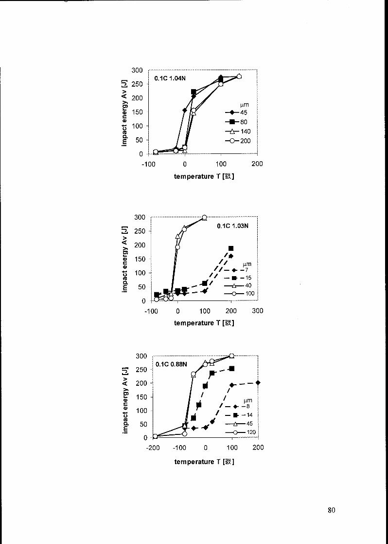
impactenergyAv
[J]
-».
-k
mro
en
oen
oai
oo
oo
oo
CD 3 o CD
D)
CD SS!
roO O O O o o roO O
impactenergyAv
[J]
-k
-k
ro
ro
co
en
oen
oen
oo
oo
oo
oo
impactenergyAv
[J]
-»
ro
ro
eo
en
oen
oo
oo
o
oi
i
o
p*
<DO
3 cir-^
<D
\\
\
Q)
_l.
kk
3ss ss
"m
ro
-S
J
{*••:*
O o
-k
*.
->
~j5
Zoo
oi
d
eo
o-
o
o
o o
CD 3 "O (D
-i
U CD SSÜ
o o roo o
oo
o

Fig.7-24 (below): grain size effect on the ductile to brittle transition phenomena in niobium containing
alloys with different nitrogen content
300
2 250
>
< 200>»U)
CD 150c
CD
Ü100
re
Q.
E 50
0
300
5 250
>
< 200
D)
a> 150c
a
"5 100re
Q.
E 50
100 200 300
temperature T [IX]
0.09C 1N0.05Nb
-100 0 100 200 300
temperature T [lu]
>
<
E?
c
CD
*•>
ÜreQ.
E
300
250
200
-100 0 100
temperature T [IK.]
200
81

In alloys with grain size smaller than 20pm precipitation of chromium nitrides in the austenite
occurred, resulting in lower toughness compared with the same alloys with bigger grain size
(doted lines in Fig.7-23/24). Therefore it was not possible to distinguish the grain size effect
on the ductile to brittle transition for grain size smaller than 20 um.
Fig. 7-25 shows the ductile to brittle transition temperature as a function of grain size with a
microstructure fully austenitic.
r^ 200mni—
r-
ffi 150
H
C
o 1004-i
</>c
2 504-i
<D
'k. 0J2
O4-i
CD -50
+*
O
3
o -100
CK) cracks!!
-x- -
-^j -y.*
cracks!!
.aG
_û_ 4 ù.
A A
-A._^_-
A1.04N
D 1.27N
A 0.95N 0.05Nb
x1.25N0.05Nb
O 1.03N
• 0.88N
1N0 05Nb
0 50 100 150 200 250 300
grain size D [pm]
Fig.7-25: grain size effect on the ductile to brittle transition temperature
Unlike in ferritic steels, a fine grain structure has no advantageous effect on the ductile to
brittle behaviour. The ductile to brittle transition temperature was found rather independent of
the grain size in the range 30-K300 pm, a result that confirms results from other authors
[Uggo92, Tomo90J.
As described in section 3.5 the ductile to brittle transition in HNS is due to a strong
temperature influence on yield strength, which can reach very high values for very low
temperature.To prove this, tensile tests at three temperatures: -75 / 25 / 250°C were carried out on two
alloys with 0.88 and 1.03 wt% N in solid solution and different grain size; results are reportedin fig. 7-26, 7-27 and 7-28.
As expected, with decreasing temperature, the yield strength increases very rapidly and the
same trend was found for the coefficient ky. Higher ky values cause a decreasing in the
G • ycleavage fracture stress (according to <jf = A -j=) and therefore the (11 l)-cleavage stress
ky -4d
can be reached without extensive plastic deformation, culminating in a brittle fracture.
82
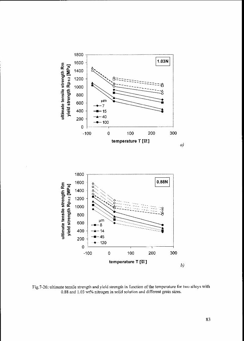
1800
F1600
on
sz
ra
CL.1400
O)-*
c
Oio
1200k. a
(/> on 1000et sz
(0r c
800
d)
a>k.
m600
*J
m o
F <u 400^3 >.
3 200
-100 0 100 200
temperature T [lï]
300
a)
1800
F ,__,
on0.
sz SD)c es
CDk. Q
W on
0) sz4-i
in O)
c l:
0) Suû> </>
re a
F a>
+3 >.
-100 0 100 200 300
temperature T [IÄ]b)
Fig.7-26: ultimate tensile strength and yield strength in function of the temperature for two alloys with
0.88 and 1.03 wt% nitrogen in solid solution and different grain sizes.
83

1400
re 1200CL
S1000
o
n,
on 800
sz4-i
C)c
600a>k.
CO 400TJ
a>
> 200
5 10
(grain size)"1'2 [mm"1'2]
15
1200
5 10
(grain size)"1'2 [mm"1'2]
15
Fig.7-27:Hall-Petch curves for alloys containing 0.88 and 1.03 wt% nitrogen in solid solution at
different temperature
1000
£ 800
S
o 600
.£ 400
g 200u
0
D0.88N
1.03 N
Fi
-75 25 250
temperature T [IK]
£.7-28: influence of the temperature on the coefficient ky and Ro in the Hall-Petch equation.
-75 25 250
temperature T [iH]
84

As no grain size effect on DBTT was seen, the origin of the big scatter band in Fig.7-22 most
likely lies in the experimental procedure carried out to determine the DBTT from the impact
energy tests: more impact energy tests should be carried out at different temperatures with a
narrow gap between each other.
7.4 DISCUSSION
Nitrogen in solid solution was increased up to 1.34 weight percent without overpressure
adjusting the other alloying elements: Cr, Mn and Ni in order to increase the nitrogen
solubility in the liquid and in the solid phase avoiding porosity in the ingots duringsolidification.
In small samples grain boundary hardening was extended down to grain size of 0.6 urn in
HNS with 1.2wt% N in solid solution (yield stress of-2000 MPa) and 0.25 pm in AISI 316
(yield tress -1000 MPa); the Hall-Petch equation was found valid even at such a small grainsizes.
Relations similar to the Hall-Petch law were found to describe the dependence on the grainsize of ultimate tensile stress and ductility. In particular with decreasing the grain size, the
ultimate tensile strength was found to increase and the ductility to decrease; the ductility can
drop to very low values in presence of very high level of nitrogen in solid solution.
With a judicious combination of all four strengthening mechanism a new record in yield
strength in HNASS was achieved: 3600 MPa in round bars with 5 mm in diameter.
Grain boundary hardening, dislocation hardening and precipitation hardening by nitrogenstrain ageing were found to increase the mechanical strength but with adverse effect on
ductility; on the contrary, solid solution hardening by nitrogen increases both strength and
ductility at the same time.
A comparison between strength and ductility in samples with different strengtheningmechanisms (singly and combined) showed how the same combination of strength and
ductility is achieved independent from the strengthening mechanisms applied.This gives a new idea toward the development of ultrahigh strength austenitic stainless steels
in bulk materials. In big samples was shown that grain refining cannot be extended below
6-^7pm even by addition of niobium; in bulk materials dislocation hardening can be used to
increase furthermore the strength in spite of this limit.
For this reasons, the next task was to study the mechanical properties of HNS during hot
rolling, a processing route which allows to add dislocation hardening as further strengtheningmechanism if the hot deformation is carried out below the recrystallization temperature
regime allowing retention of deformation (warm-hardening).The ductile to brittle transition temperature (DBTT) was found depending not only on N and
C but also on other alloying elements, primarily Nb, Cr, Mn and Ni. In contrast, DBTT was
found rather independent from grain size in the range 30-^300 pm.
85
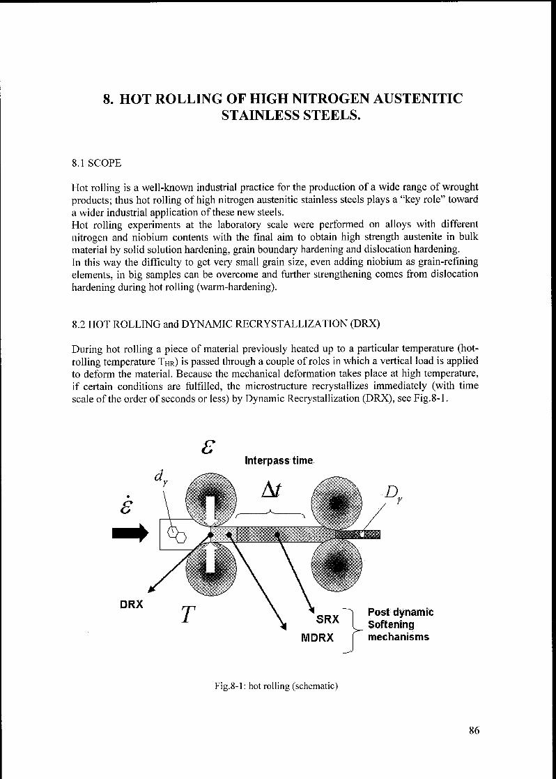
8. HOT ROLLING OF HIGH NITROGEN AUSTENITIC
STAINLESS STEELS.
8.1 SCOPE
Hot rolling is a well-known industrial practice for the production of a wide range of wrought
products; thus hot rolling of high nitrogen austenitic stainless steels plays a "key role" toward
a wider industrial application of these new steels.
Hot rolling experiments at the laboratory scale were performed on alloys with different
nitrogen and niobium contents with the final aim to obtain high strength austenite in bulk
material by solid solution hardening, grain boundary hardening and dislocation hardening.In this way the difficulty to get very small grain size, even adding niobium as grain-refining
elements, in big samples can be overcome and further strengthening comes from dislocation
hardening during hot rolling (warm-hardening).
8.2 HOT ROLLING and DYNAMIC RECRYSTALLIZATION (DRX)
During hot rolling a piece of material previously heated up to a particular temperature (hot-
rolling temperature THr) is passed through a couple of roles in which a vertical load is appliedto deform the material. Because the mechanical deformation takes place at high temperature,
if certain conditions are fulfilled, the microstructure recrystallizes immediately (with time
scale of the order of seconds or less) by Dynamic Recrystallization (DRX), see Fig. 8-1.
SInterpass time
Fig.8-1 : hot rolling (schematic)
86
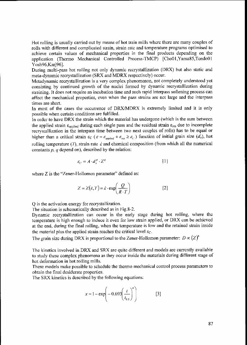
Hot rolling is usually carried out by means of hot train mills where there are many couples of
rolls with different and complicated strain, strain rate and temperature programs optimised to
achieve certain values of mechanical properties in the final products depending on the
application (Thermo Mechanical Controlled Process-TMCP) [Cho01,Yama85,Tendo01
Yosh96,Karj96].
During multi-pass hot rolling not only dynamic recrystallization (DRX) but also static and
meta-dynamic recrystallization (SRX and MDRX respectively) occur.
Metadynamic recrystallization is a very complex phenomenon, not completely understood yet
consisting by continued growth of the nuclei formed by dynamic recrystallization during
straining. It does not require an incubation time and such rapid interpass softening process can
affect the mechanical properties, even when the pass strains are not large and the interpasstimes are short.
In most of the cases the occurrence of DRX/MDRX is extremely limited and it is only
possible when certain conditions are fulfilled.
In order to have DRX the strain which the material has undergone (which is the sum between
the applied strain sappiied during each single pass and the residual strain sres due to incomplete
recrystallization in the interpass time between two next couples of rolls) has to be equal or
higher than a critical strain £c ( s = ehai
+ £m ^£c) function of initial grain size (d0), hot
rolling temperature (7), strain rate s and chemical composition (from which all the numerical
constants/?, q depend on), described by the relation:
ec=A-d0p-Z" [1]
where Z is the "Zener-Hollomon parameter" defined as:
Z = Z(è,T)=è-txJ-f-\ [2]\R-l J
Q is the activation energy for recrystallization.The situation is schematically described as in Fig.8-2.
Dynamic recrystallization can occur in the early stage during hot rolling, where the
temperature is high enough to induce it even for low strain applied, or DRX can be achieved
at the end, during the final rolling, when the temperature is low and the retained strain inside
the material plus the applied strain reaches the critical level sc-
The grain size during DRX is proportional to the Zener-Hollomon parameter: D oc (z)
The kinetics involved in DRX and SRX are quite different and models are currently available
to study these complex phenomena as they occur inside the materials during different stage of
hot deformation in hot rolling mills.
These models make possible to schedule the thermo mechanical control process parameters to
obtain the final desiderate properties.The SRX kinetics is described by the following equations:
x = \- exp
f „Y^1
0.693
\hs J
[3]
87
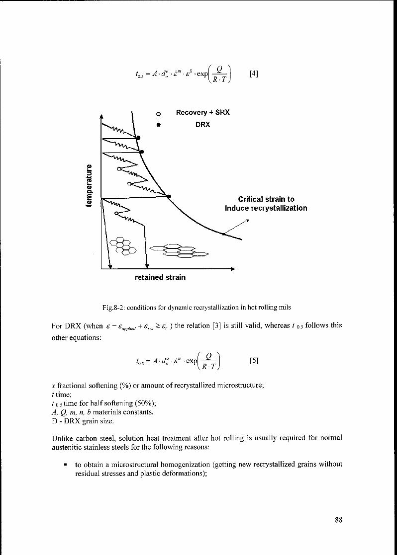
f n A
t05 = A-dao-èm-£"expQ
r-t)[4]
i_
3
a>Q.
Ea>
o Recovery + SRX
* DRX
Critical strain to
Induce recrystallization
retained strain
Fig.8-2: conditions for dynamic recrystallization in hot rolling mils
For DRX (when s = sapplwd + sres > sc ) the relation [3] is still valid, whereas t 0.5 follows this
other equations:
tQ5 = A da0 èm expQ
R-T[5]
x fractional softening (%) or amount of recrystallized microstructure;
t time;
10.5 time for half softening (50%);
A, Q, m, n, b materials constants.
D - DRX grain size.
Unlike carbon steel, solution heat treatment after hot rolling is usually required for normal
austenitic stainless steels for the following reasons:
to obtain a microstructural homogenization (getting new recrystallized grains without
residual stresses and plastic deformations);
88

to improve the corrosion resistance (removing precipitates which normally forms
during hot rolling and the subsequent cooling process).
This means that the microstructure of these steels is controlled mostly by annealing, duringwhich grain sizes smaller than 100pm are hardly achieved. Solution heat treatment after hot
rolling lowers the yield strength, which sometimes makes structural use of the stainless steels
plates unfeasible. In certain applications where a decreased corrosion resistance in some
environments or a limited ductility or formability (for the high internal stress or precipitates)is still acceptable, the annealing process can be avoided (with positive effect also on the final
costs).These are the reasons why hot rolling of austenitic stainless steels can be carried out
according two modalities:
a) hot rolling with a final rolling temperature below Tdrx (temperature at which dynamic
recrystallization occurs) resulting in austenite with microstructure of fine grains
slightly elongated in the rolling direction (see Fig.8-2a);
b) hot rolling with a final rolling temperature above Tdrx, in which a more homogeneousmicrostructure with equiaxed grains is achieved (see Fig.8-2è).
With the first practice higher mechanical strength are achieved, because ofthe fine dislocation
hardened microstructure generated during hot rolling (warm-working) [lke96, TendoOl].In the case of normal austenitic stainless steels, warm working is carried out at temperature
below about 900°C and can extend to temperatures as low as 700°C. Of course with lower
finishing rolling temperatures higher strength levels are achieved.
The response to warm working not only depends on finishing temperature but is also
influenced by composition.The final mechanical properties achieved following the second possibility relies only upon the
grain refining obtained during the last step of deformation, and usually are lower [Ike96,
TendoOl]. Extreme grain refining can be achieved only by careful choice of hot rolling
parameters among each rolling mill stage in order to avoid as much as possible any form of
post dynamic softening mechanisms (Dynamic Recrystallization and Metadynamic
Recrystallization Controlled Process were developed for this purposes [ChoOl]).
In this way grain sizes around 20pm can be obtained [Yama90].
8.3 MATERIALS AND METHODS
Hot rolling experiments at the laboratory scale were performed by means of a small hot
rolling equipment with only one couple of rolls, and due to power supply limitations it was
not possible to apply a big degree of deformation during a single rolling step; therefore onlythe influence on the final mechanical properties of the hot rolling temperature at fixed appliedstrain and strain rate was investigated.
Hot-rolling experiments were performed in the way shown in Fig. 8-3.
Samples were put for about thirty minutes into an electric furnace 0min maintained at the hot
rolling temperature of interest; then hot rolled in different steps down to the final thickness
requested.
89

( a ) Finish rolling temperature < TDRX
Annealing:coarse y grains
LDEX
Break-down rolling:homogenization of
microstructure by
multiple DRX and SRX
....
f ^Finish rolling: X. / .
Work hardening _Sy j__ .
accelerated coolingto prevent softeningand precipitation
>10K/s
i Carbide precipitation1
V*t
= austenite with small grains deformed
(high strength = grain ref. + work hard.)
( b ) Finish rolling temperature > TDRX
Annealing:coarse y grains
accelerated coolingto prevent softeningand precipitation
>10K/s
Break-down rolling and finish rolling:
homogenization of microstructure and elevated
grain refinign by multiple DRX and SRX
r -i
i \
t \
V i v
/ | Carbide precipitationi \
t \
-+t
= austenite with small grains
Fig. 8-2: thermo mechanical controlled processing applied for austenitic stainless steel
90
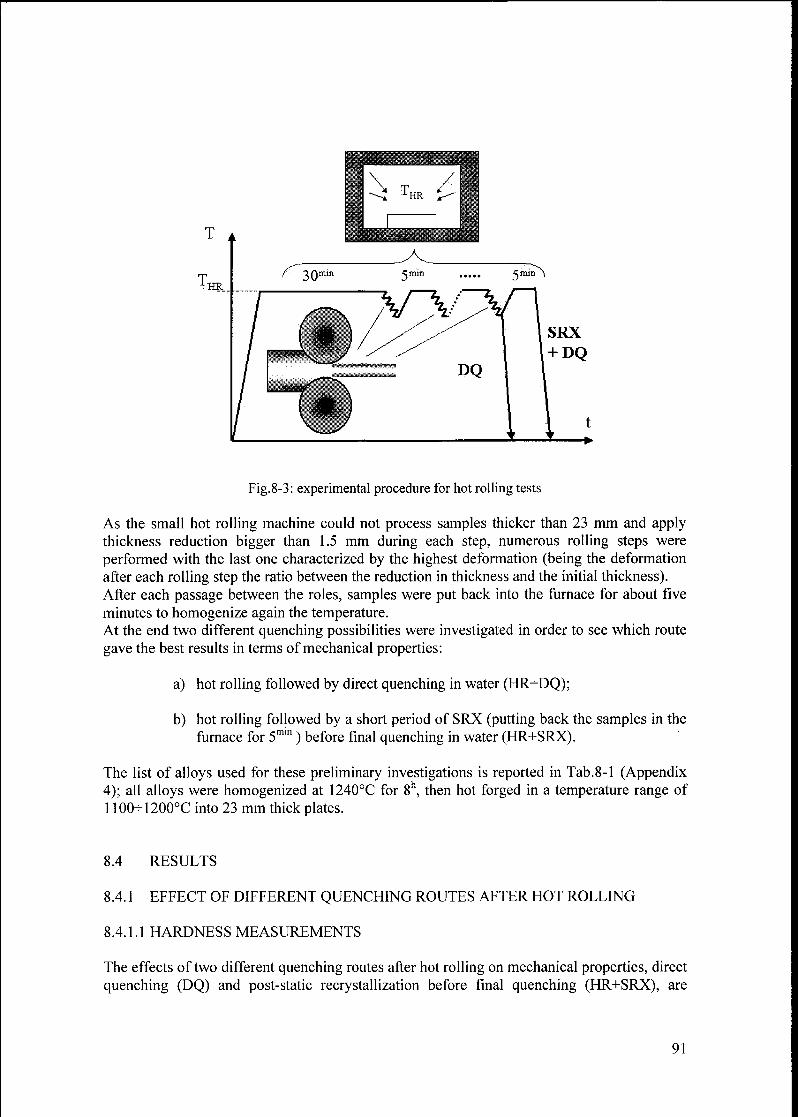
T A
lHR
SRX
+ DQ
Fig.8-3: experimental procedure for hot rolling tests
As the small hot rolling machine could not process samples thicker than 23 mm and applythickness reduction bigger than 1.5 mm during each step, numerous rolling steps were
performed with the last one characterized by the highest deformation (being the deformation
after each rolling step the ratio between the reduction in thickness and the initial thickness).After each passage between the roles, samples were put back into the furnace for about five
minutes to homogenize again the temperature.At the end two different quenching possibilities were investigated in order to see which route
gave the best results in terms of mechanical properties:
a) hot rolling followed by direct quenching in water (HR+DQ);
b) hot rolling followed by a short period of SRX (putting back the samples in the
furnace for 5mm ) before final quenching in water (HR+SRX).
The list of alloys used for these preliminary investigations is reported in Tab.8-1 (Appendix4); all alloys were homogenized at 1240°C for 8h, then hot forged in a temperature range of
1100-1200°C into 23 mm thick plates.
8.4 RESULTS
8.4.1 EFFECT OF DIFFERENT QUENCHING ROUTES AFTER HOT ROLLING
8.4.1.1 HARDNESS MEASUREMENTS
The effects of two different quenching routes after hot rolling on mechanical properties, direct
quenching (DQ) and post-static recrystallization before final quenching (HR+SRX), are
91

summarized in Fig. 8-4, which shows hardness measurement (HVio) in austenite with 1.2wt%
nitrogen on samples hot-rolled at 1020° /1050° /1100°C and degrees of deformation
applied during a single step in the range of 20-60%; these values are the total strain which the
material has undergone if complete SRX occurred during the 5mm of interpass time spent into
the furnace, resulting in new unstrained grains (eres~0). To achieve this condition the samplesused in this investigation were very small (about 10x10x20 mm).
500
450
o
$I
in
% 350
c
TJ
reJC
400
300
250
200
20 40 60
hot deformation e [%]
80
•10201* HR+SRX
1050IÏ HR+SRX
1100UI HR+SRX
Fig.8-4: Hardness of alloy containing 1.2 wt% hot rolled and quenched following twodifferent routes
Samples directly quenched into water show higher level of hardness, hence mechanical
strength, than the ones who have undergone post static recrystallization heat treatment before
final quenching.Hardness, hence mechanical strength, increases with increasing the degree of deformation
during hot rolling at any temperature because the condition for DRX was not achieved,
resulting in dislocation hardening, as shown from Fig.8-5a/è where deformed grains in the
rolling direction can be seen.
Very high hardness values were measured in samples hot rolled at 1020°C where the
dislocation hardening was more effective due to the lower temperature.The effect of 5 minutes of post static recrystallization was to decrease the hardness in all
conditions investigated due to SRX and grain growth resulting in bigger grains, see Fig.8-5c/d.
8.4.1.2 TENSILE PROPERTIES AND TOUGHNESS
A comparison between mechanical properties after hot rolling followed by two quenching
practices, and after static recrystallization heat treatments carried out on similar materials
previously cold work is summarized in Fig. 8-6 and 8-7.
92
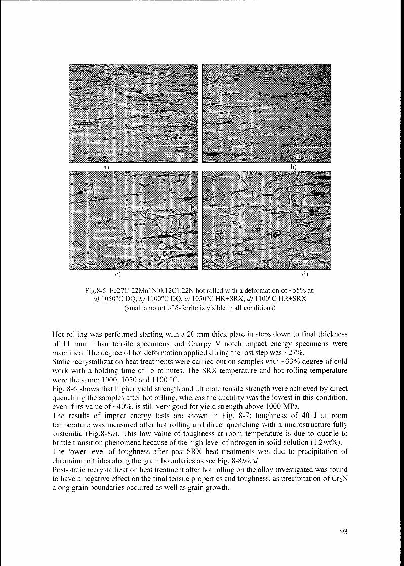
(small amount of 8-ferrite is visible in all conditions)
Hot rolling was performed starting with a 20 mm thick plate in steps down to final thickness
of 11 mm. Than tensile specimens and Charpy V notch impact energy specimens were
machined. The degree of hot deformation applied during the last step was -27%.
Static recrystallization heat treatments were carried out on samples with -33% degree of cold
work with a holding time of 15 minutes. The SRX temperature and hot rolling temperature
were the same: 1000, 1050 and 1100 °C.
Fig. 8-6 shows that higher yield strength and ultimate tensile strength were achieved by direct
quenching the samples after hot rolling, whereas the ductility was the lowest in this condition,
even if its value of-40%, is still very good for yield strength above 1000 MPa.
The results of impact energy tests are shown in Fig. 8-7; toughness of 40 J at room
temperature was measured after hot rolling and direct quenching with a microstructure fullyaustenitic (Fig.8-8a). This low value of toughness at room temperature is due to ductile to
brittle transition phenomena because of the high level of nitrogen in solid solution (1.2wt%).The lower level of toughness after post-SRX heat treatments was due to precipitation of
chromium nitrides along the grain boundaries as see Fig. %-%b/c/d.
Post-static recrystallization heat treatment after hot rolling on the alloy investigated was found
to have a negative effect on the final tensile properties and toughness, as precipitation of Q2N
along grain boundaries occurred as well as grain growth.
93

1200
1000
ro"« 800c o.
£ë 600
400
200
CW+SRX
DHR
DHR+SRX
1000 1050 1100
temperature T [lu]
1400
r-. 1200
= | 1000
800
600
I g> 400
= i 200(A
0
(A 2
C-*
4-1
re
CW+SRX
DHR
D HR+SRX
1000 1050
temperature T [lu]
1100
.2 <
s,"
k?3
ö .2
CW+SRX
DHR
DHR+SRX
1000 1050
temperature T [UJ]
1100
Fig.8-6: yield strength, ultimate tensile strength and ductility of alloy containing 1.2wt% N after three
different process routes: cold working (CW) + SRX ; hot rolling + direct quenching (HR) and hot
rolling + post-SRX before final quenching (HR+SRX).
94

" 40
>
<
>>G)k.
0)Co
4-1
u
(0Q.
E
30
20
10
1000 1050 1100
temperature T [lu]
DHR
D HR+SRX
Fig.8-7: toughness of alloy containing 1.2wt% N after hot rolling + direct quenching (HR) and hot
rolling + post-SRX before final quenching (HR+SRX).
"m->: w^i;'**"* h 'IE
c) d)
Fig.8-8: microstructure of alloy Fe30Crl5Mn3Ni0.08Cl.20N0.02Nb after hot rolling at 1100°C and:
a) direct quenched; b) quenched after SRX@1000°C/5m'n ;
c) quenched after SRX@1000°C/5mm ; d) quenched after SRX@1100°C/5min .
Even if the problem of C^N precipitation could be eliminated choosing a higher temperature
or alloys more thermodynamically stable, the reduction in mechanical strength by grain
growth would remain, hence post-static recrystallization heat treatment after hot rolling
95

should be avoided when higher mechanical properties are requested in the final state,
preferring hot rolling followed by direct quenching.
8.4.2 MECHANICAL PROPERTIES OF ALLOYS HOT ROLLED AND SRX
High mechanical properties, in terms of yield strength and ultimate tensile strength, were
expected by hot rolling and direct quenching fully austenitic alloys in the temperature range
of 1020^-1050°C, where DRX does not occur, taking advantages from work hardening
(according to the hot rolling practice described in Fig.8-2a).Summaries of results of hot rolling and static recrystallization tests performed on alloys with
different nitrogen and niobium contents (chemical composition in Tab.8-1) fulfilling the
above-mentioned requirement are shown in Fig. 8-9/10/11 and 12.
SRX heat treatments were carried out on alloys cold rolled for a degree of cold work of
-33%, then recrystallized at different temperature for 20 to 60 minutes.
Alloys hot rolled had an initial thickness of 22mm (after hot forging), which was reduced to
12mm in 7 steps. The direct quenching route was followed.
Fig. 8-9 shows the yield strength and the ultimate tensile strength of alloys hot rolled at
different temperatures.
(0 10
F O.
Si
3F
d onQ.
en
j= c
O) u>
c 4-»
V Wk.4J d)in
TJinc
0> V
><
ituu -
1200 -
Rm
1000 - AX yf *k*****.
O— n *"-
.
°
800RP0 2
600 -
-A-HR1.20N0.02Nb
400 -D-HR0.9N
200 -
-O-HR0.84N0 10Nb
—O-HR0.88N0 2Nb
0 -
1 1 1 1 1 1
980 1000 1020 1040 1060 1080 1100 1120
hot rolling temperature THr [Ia]
Fig.8-9: yield strength and ultimate tensile strength as function of hot rolling temperature
Fig. 8-10/11/12 show the yield strength, the ultimate tensile strength and the ductility
(measured as elongation to fracture) in function of the impact energy respectively.As a general trend, the toughness increases with decreasing yield strength and ultimate tensile
strength but hot rolled alloys always show higher mechanical properties at the same level of
toughness.The ductility increases with increasing toughness but hot rolled alloys show a lower level of
toughness, compared with the same alloys SRX.
The increasing in mechanical strength by dislocation hardening is gained at expense of
ductility, as remarked at the end of chapter 7.
96

1200
£ 1000
S 800a
on
B 600O)c<D
5 400
<D
200
0
-— SRX 0 83N 0 02Nb
-à- SRX 1 20N 0 02Nb
-ù- HR 1 20N 0 02Nb
-O-HR0 84N0 10Nb
-+- SRX 0 87N 0 02Nb
-m- SRTX 0 9N
-D- HR 0 9N
-o- HR 0 88N 0 2Nb
50 100 150 200 250
impact energy Av [J]
300
Fig.8-10: yield strength versus toughness in alloys hot rolled and statically recrystallized
re
0.
c
4-f
in
o
1400
1200
E* 1000
800
= 600in£
0)4-i
0>4-»
m
ES 200
400
-SRX0 83N0 02Nb
-SRX1 20N0 02Nb
-HR1 20N0 02Nb
•HR0 84N0 10Nb
-SRX0 87N0 02Nb
SRX0 9N
HR0 9N
-HR0 88N0 2Nb
50 100 150 200
impact energy Av [J]
250 300
Fig. 8-11 : ultimate tensile strength versus toughness in alloys hot rolled and statically recrystallized
97

60
p-1
^e bU
in
<V 404-»
o(0
30O•M
£
O ?0+j
re
D)c
o 10
<^°-
-SRX0.83N0.02Nb
-SRX1 20N0.02Nb
-HR1.20N0.02Nb
-HR0.84N0.10Nb
-SRX0 87N0.02Nb
-SRTX0.9N
-HR0.9N
-HR0.88N0.2Nb
50 100 150 200
impact energy Av [J]
250 300
Fig.8-12: ductility versus toughness in alloys hot rolled and statically recrystallized
Fig. 8-13 shows the yield strength in function ofthe grain size in hot rolled and SRX alloys.
re
o_
o
Q.
on.
c
aii_
4->
in
1200
1000
800
600
400
200
0
100|im 50|im lO^rr 5|im 3(imI I I 1 1
HotTOlled
O /Q.A--
. +SRX
SRX1.2N+0.02Nb m SRX0.9N
A SRX0.88N0.2Nb • SRX 0.84N 0.1Nb
D HR0.9N A HR0.88N0.2Nb
O HR 0.84N 0.1Nb O HR1.2N0.02Nb
10 15 20
(grain size)"1'2 [mm'1'2]
Fig.8-13: yield strength in function of grain sizes in different alloys hot rolled and SRX
As expected, hot rolled alloys showed yield strengths, higher than the ones SRX, with the
same grain size, as another strengthening mechanisms were involved to determine the final
properties.
98

Hot rolled alloys containing niobium showed smaller grain size; hence niobium is useful to
control the grain growth also during hot rolling.TEM analysis was carried out on some samples hot rolled at 1060°C (see Fig. 8-14) and
1090°C(seeFig.8-15).
Fig.8-14: Fe25Cr16Mn2Ni0.1C0.1Nb0.84N Hot rolled @ 1060°C
Fig.8-15: Fe25Cr16Mn2Ni0.1C0.1Nb0.9N Hot rolled @ 1090°C
Fig. 8-14/15 show the typical "cells structure", with very high level of dislocation density. In
Fig. 8-15 the "walls" of the cells are better defined and inside the cells it is possible to see
clearly a big number of dislocations. The dislocation density was higher in the sample hot
rolled at lower temperature.
99
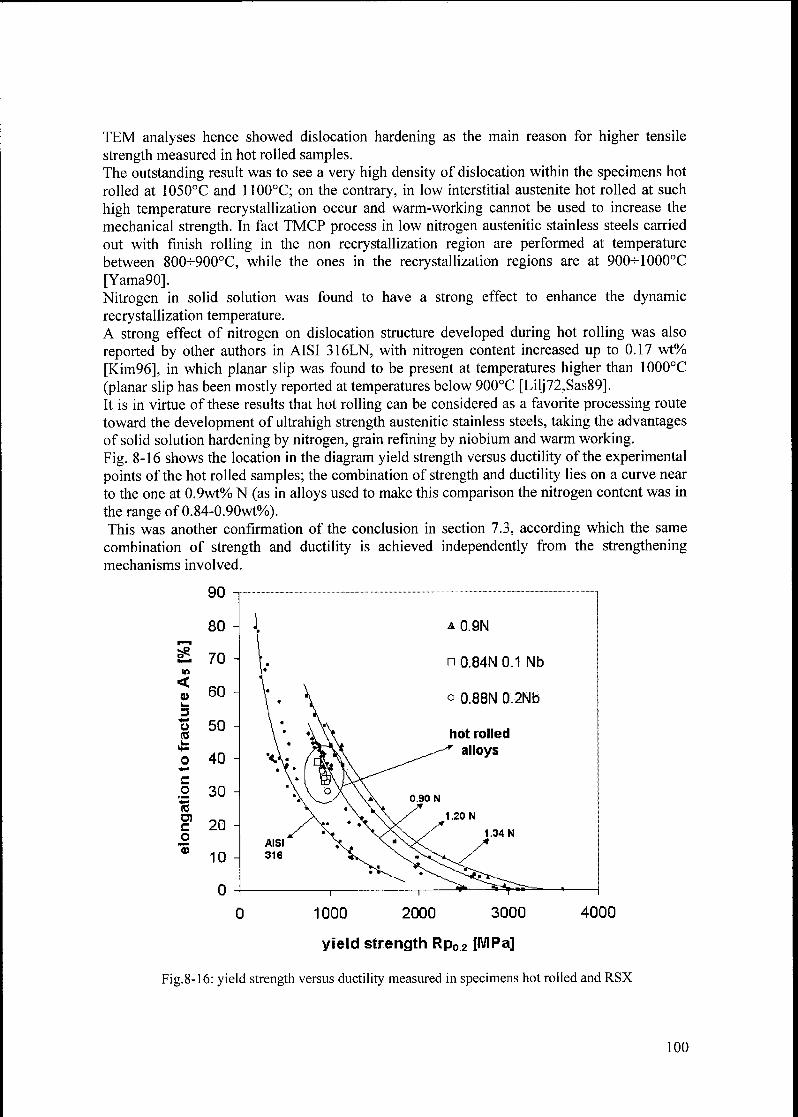
TEM analyses hence showed dislocation hardening as the main reason for higher tensile
strength measured in hot rolled samples.The outstanding result was to see a very high density of dislocation within the specimens hot
rolled at 1050°C and 1100°C; on the contrary, in low interstitial austenite hot rolled at such
high temperature recrystallization occur and warm-working cannot be used to increase the
mechanical strength. In fact TMCP process in low nitrogen austenitic stainless steels carried
out with finish rolling in the non recrystallization region are performed at temperature
between 800^900°C, while the ones in the recrystallization regions are at 900^-1000°C
[Yama90].
Nitrogen in solid solution was found to have a strong effect to enhance the dynamic
recrystallization temperature.A strong effect of nitrogen on dislocation structure developed during hot rolling was also
reported by other authors in AISI 316LN, with nitrogen content increased up to 0.17 wt%>
[Kim96], in which planar slip was found to be present at temperatures higher than 1000°C
(planar slip has been mostly reported at temperatures below 900°C [Lilj72,Sas89].It is in virtue of these results that hot rolling can be considered as a favorite processing route
toward the development of ultrahigh strength austenitic stainless steels, taking the advantagesof solid solution hardening by nitrogen, grain refining by niobium and warm working.
Fig. 8-16 shows the location in the diagram yield strength versus ductility of the experimental
points of the hot rolled samples; the combination of strength and ductility lies on a curve near
to the one at 0.9wt% N (as in alloys used to make this comparison the nitrogen content was in
the range of 0.84-0.90wt%).This was another confirmation of the conclusion in section 7.3, according which the same
combination of strength and ductility is achieved independently from the strengtheningmechanisms involved.
o
<Vk.
34->
o
co
co
9)
0 1000 2000 3000 4000
yield strength Rp02 [MPa]
Fig.8-16: yield strength versus ductility measured in specimens hot rolled and RSX
100
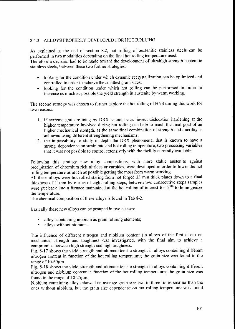
8.4.3 ALLOYS PROPERLY DEVELOPED FOR HOT ROLLING
As explained at the end of section 8.2, hot rolling of austenitic stainless steels can be
performed in two modalities depending on the final hot rolling temperature used.
Therefore a decision had to be made toward the development of ultrahigh strength austenitic
stainless steels, between these two further strategies:
• looking for the condition under which dynamic recrystallization can be optimized and
controlled in order to achieve the smallest grain sizes;
• looking for the condition under which hot rolling can be performed in order to
increase as much as possible the yield strength in austenite by warm working.
The second strategy was chosen to further explore the hot rolling ofHNS during this work for
two reasons:
1. if extreme grain refining by DRX cannot be achieved, dislocation hardening at the
higher temperature involved during hot rolling can help to reach the final goal of an
higher mechanical strength, as the same final combination of strength and ductility is
achieved using different strengthening mechanisms;2. the impossibility to study in depth the DRX phenomena, that is known to have a
strong dependence on strain rate and hot rolling temperature, two processing variables
that it was not possible to control extensively with the facility currently available.
Following this strategy new alloy compositions, with more stable austenite against
precipitation of chromium rich nitrides or carbides, were developed in order to lower the hot
rolling temperature as much as possible getting the most from warm working.All these alloys were hot rolled staring from hot forged 23 mm thick plates down to a final
thickness of 11mm by means of eight rolling steps; between two consecutive steps samples
were put back into a furnace maintained at the hot rolling of interest for 5min to homogenizethe temperature.The chemical composition ofthese alloys is found in Tab 8-2.
Basically these new alloys can be grouped in two classes:
alloys containing niobium as grain refining elements;
alloys without niobium.
The influence of different nitrogen and niobium content (in alloys of the first class) on
mechanical strength and toughness was investigated, with the final aim to achieve a
compromise between high strength and high toughness.
Fig. 8-17 shows the yield strength and ultimate tensile strength in alloys containing different
nitrogen content in function of the hot rolling temperature; the grain size was found in the
range of 10-60pm.
Fig. 8-18 shows the yield strength and ultimate tensile strength in alloys containing different
nitrogen and niobium content in function of the hot rolling temperature; the grain size was
found in the range of 10-25pm.Niobium containing alloys showed an average grain size two to three times smaller than the
ones without niobium, but the grain size dependence on hot rolling temperature was found
101
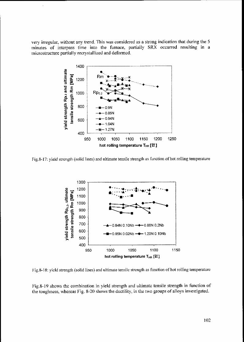
very irregular, without any trend. This was considered as a strong indication that during the 5
minutes of interpass time into the furnace, partially SRX occurred resulting in a
microstructure partially recrystallized and deformed.
1400a>4J
(0,__,
h re
4*3 a. 12003
fe
T3c
Ere
CM
a:
r1000
a.on
4-»
c
sz4-»
k.4-1 800
c0) a>
4-i
w
a
(0c 600
.2
400
Rm~V--*.. x
Rp0 2Xi:>«^^^^*"-~-A«--**^ a^
N^--0 9N
"~—
—^-0 85N
—*— 094N
-•—104N
-*-127N
950 1000 1050 1100 1150 1200
hot rolling temperature THr [1Ü]
1250
Fig. 8-17: yield strength (solid lines) and ultimate tensile strength as function of hot rolling temperature
1300
£>_
1200re re
| | 1100
3. 1" 1000
Sac900
800
700
600
500
400
a (-on 4-»
sz c
D) k.
r 4J
(D (/)k.
a>
in _
TJ c
0) <D
-0 84N010Nb'
-0 95N0 02Nb-
-0 88N0 2Nb
-1 20N0 10Nb
950 1000 1050 1100
hot rolling temperature THR [IK]
1150
Fig.8-18: yield strength (solid lines) and ultimate tensile strength as function of hot rolling temperature
Fig.8-19 shows the combination in yield strength and ultimate tensile strength in function of
the toughness, whereas Fig. 8-20 shows the ductility, in the two groups of alloys investigated.
102
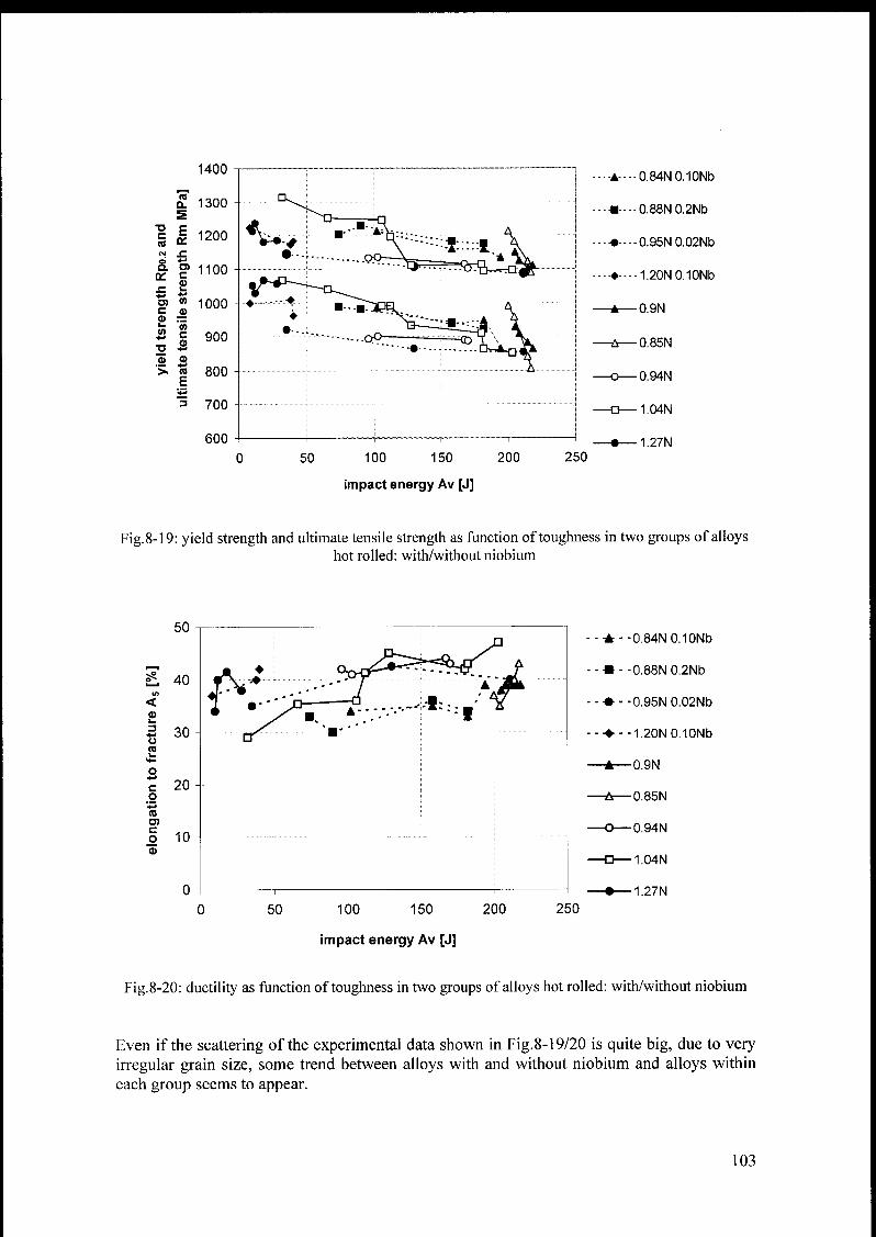
1400
Q. 1300
SDCre
Ea:
1200
CM £
8.ce
O)Co
1100
r k.
O) (A 1000L. Ci<0
a
inc 900
m Ä> m
E800
= 700
600
50 100 150 200
impact energy Av [J]
250
A---084N0.10Nb
-----0.88N0.2Nb
-•----0.95N0.02Nb
--•--1.20N0.10Nb
-A—0.9N
-ù—0.85N
-O—0.94N
-G—1.04N
-•—1.27N
Fig.8-19: yield strength and ultimate tensile strength as function of toughness in two groups of alloyshot rolled: with/without niobium
50
40
<
a>k.
34-1 30orek.
4-
o
c 20o
4-1
re
enc
o 10
50 100 150 200
impact energy Av [J]
250
A--0.84NO.10Nb
«--0.88N0.2Nb
-•0.95N0.02Nb
--1 20N0 10Nb
-A—0.9N
-Ù—0.85N
-O—0.94N
-O—1.04N
-•—1.27N
Fig.8-20: ductility as function of toughness in two groups of alloys hot rolled: with/without niobium
Even if the scattering of the experimental data shown in Fig.8-19/20 is quite big, due to very
irregular grain size, some trend between alloys with and without niobium and alloys within
each group seems to appear.
103

A high level of nitrogen (> 1.2wt%), together with a high level of niobium (0.10wt%) results
in high strength (Rpo2 > 1000 MPa, Rm > 1100 Mpa) but with a very low level of toughness
(< 50 J) due to the ductile to brittle transition (as the microstructure was always fully
austenitic).
Very high level of toughness (> 200 J) and high level of mechanical properties (Rpo 2 from
800 + 1000 MPa and Rm from 1100 h- 1200 MPa), where reached in alloys with nitrogencontent between 0.85 - 0.90wt%.
The ductility increases with increasing toughness in all alloys; niobium containing alloys with
the same nitrogen content showed a lower level of ductility compared to alloys without
niobium, but the mechanical properties were higher in the first one due to grain refining.In the alloys characterized by high toughness the ductility was found in the range 35-45%).
8.5 DISCUSSION
Nitrogen in solid solution was found to have a profound influence on the temperature of
dynamic recrystallization and hence on the thermomechanical processing and the resulting
properties. In particular, nitrogen makes dislocation hardening very active and increases the
mechanical strength even at temperatures above 1000°C.
In this way, by means of hot rolling, dislocation hardening was added to the solid solution
hardening and grain boundary hardening to develop ultrahigh strength austenitic stainless
steels in relative large quantity (bulk material).Best results in term of combination strength-toughness-ductility were found after hot rollingat 1050°C an austenite with chemical composition: Fe 25Cr 16Mn 3Ni 0.10C 0.85N, which
gave: Rp0 2~ 1000 MPa, Rm ~ 1200 MPa, A5 ~ 35% and Av ~ 200 J.
Unfortunately during hot rolling it was not possible to control the grain size properly,
resulting in a big scatter of data; however, hot rolling of HNS has all the potentiality to give
ultrahigh strength austenitic stainless steels in large quantities and in a wide range of productforms.
104
9. APPLICATIONS OF HIGH NITROGEN AUSTENITIC
STAINLESS STEELS.
High nitrogen austenitic stainless steels are currently produced by powder metallurgy and
pressure metallurgy routes, hence are quite expensive. Therefore they have found limited
applications, in fields where the high cost of investment can be tolerated due to requirementsof very high mechanical properties and resistance to corrosion in many aggressiveenvironments.
Generator rotor retaining rings are a classical application of high nitrogen austenitic stainless
steels. These components serve on all generators in all power stations of the world and are
thus indispensable for electric power generators. The function of the retaining rings is to hold
the copper conductor winding against the centrifugal forces. Generator rotor retaining rings
may be small or huge forgings and because of the high rotating frequencies are some of the
most highly stressed parts of the machine. Moreover, because of the energy loss due to Eddycurrents the retaining rings should not be ferromagnetic materials. Thus, generator rotor
retaining rings need to be made of high strength non-magnetic materials: these are generallycold worked, high nitrogen austenitic stainless steels [Stein99].Because of their superior property combinations concerning strength, ductility and corrosion
resistance, high nitrogen austenitic stainless steels are presently used also in the building
industry for bolts and other fixations were resistance to stress corrosion cracking is importantbecause the components are stressed in aggressive environments for very long time
[Stein99b], For this application they are cold worked to over 2000 MPa yield strength.It would be now possible to produce wires with yield strength over 3000 MPa convertingthem into rivets, nails or bolts. Moreover, ultrahigh strength wires have application potential,for example in bridge building.
High nitrogen nickel-free austenitic stainless steels have recently been introduced to
applications where human body fluids are in contact with the metal. Such components can be
made by melting an forging, or alternatively by powder metallurgical methods, particularlymetal injection moulding [Wohlf98,Uggo96,Menz96]. Some applications are concerning;watch cases, dental correction devices.
Anyway, even ifthe list of applications could continue, they all are very limited applications.
This situation might change in the future because now high nitrogen austenitic stainless steels
to be made without overpressure, providing the proper know-how is used, have been
developed.In this way they could be produced by means of traditional steel making facilities, they could
be cheaper than traditional austenitic stainless steel grades as they contain no or very low
nickel.
Thus wide applications of ultrahigh strength low nickel nigh nitrogen austenitic stainless
steels in the automotive industry and construction and civil engineering industry would be
possible. In each cases the compromise among ductility, strength, corrosion resistance and
moderate price will be weighted differently.
105
10. OUTLOOK
Without any doubt the best way towards a more wide applications of HNS pass trough thermo
mechanical controlled process (TMCP), for the production of diversified wrought productswith high mechanical strength and corrosion resistance.
To reach this final goal further researches should be focused on the hot workability of HNS in
as-cast condition, as the final behaviour during hot rolling is dictated by this microstructure.
Hot workability tests should start with high nitrogen steels with chemical compositionFe25Crl6Mn3Ni0.1C0.9N or the niobium alloyed version Fe25Crl6Mn3Ni0.1C0.9N0.1Nb;
and eventually more investigations related to study of other important parameters, such as
strain rate and strain during hot rolling, should be performed in order to get the best from the
TMCP. For these purposes "hot rolling simulation" on HNS should be performed with the
final aim to improve the hot workability of these steels in the as-cast condition.
The grain refining effect by niobium addition and strengthening by dislocation hardening
during hot rolling on corrosion resistance (crevice, pitting, stress corrosion cracking) was not
investigated during this work, hence further studies in this direction are necessary.
Even if with the new possibility to melt HNS with traditional steel making facilities without
overpressure, the welding problems of HNS should partially be solved, when this joining
practice has to be followed, more investigations in this direction are necessary.
The effect of very small grains (less than 20pm) on the ductile to brittle transition temperature
on high nitrogen austenitic stainless steels is still not clear; small samples and hence down-
scaled Charpy V notch impact specimens are necessary in order to achieve very small grainsize.
106

Appendix 1
DECOMPOSITION OF AUSTENITE IN AUSTENITIC
STAINLESS STEELS.
Three main kinds of precipitation may take place during decomposition of austenite in
austenitic stainless steels:
1) intermetallic phases;
2) carbides;
3) nitrides,
although other phases may also be present, such as sulphides and borides (in boron containing
steels) [Padi02, Proc89, ASM94, Gav99].
A.l INTERMETALLIC PHASES
Intermetallic phases formed between transition elements belonging to so called B-group (Mn,
Fe, Co, Ni etc.) and A-group (Ti, V, Cr, Mo etc.).The three intermetallic phases most frequently found in austenitic stainless steels are:
sigma phases (a);chi phases (x);Laves phase (r\).
Other intermetallic phases that can also occasionally be found are:
G phase;R phase;Mu (p) phase;
gamma prime (y');
gamma double prime (y");
r\- Wi{Yi phase;ô- Ni3Nb phase.
Precipitation of intermetallic phases from austenite is normally associated with undesirable
consequence like matrix depletion in alloying elements (like Cr, Mo and Nb) and reduction in
ductility, toughness and corrosion resistance.
Exceptions are y' NÎ3(A1, Ti) in precipitation-hardening iron based superalloys and the Laves
phases Fe2Nb in austenitic stainless steels since their occurrence can result in precipitation
hardening.Tab.A-1 summarized results concerning crystal structures and compositions of intermetallic
phases, which may appear in austenitic stainless steels.
107
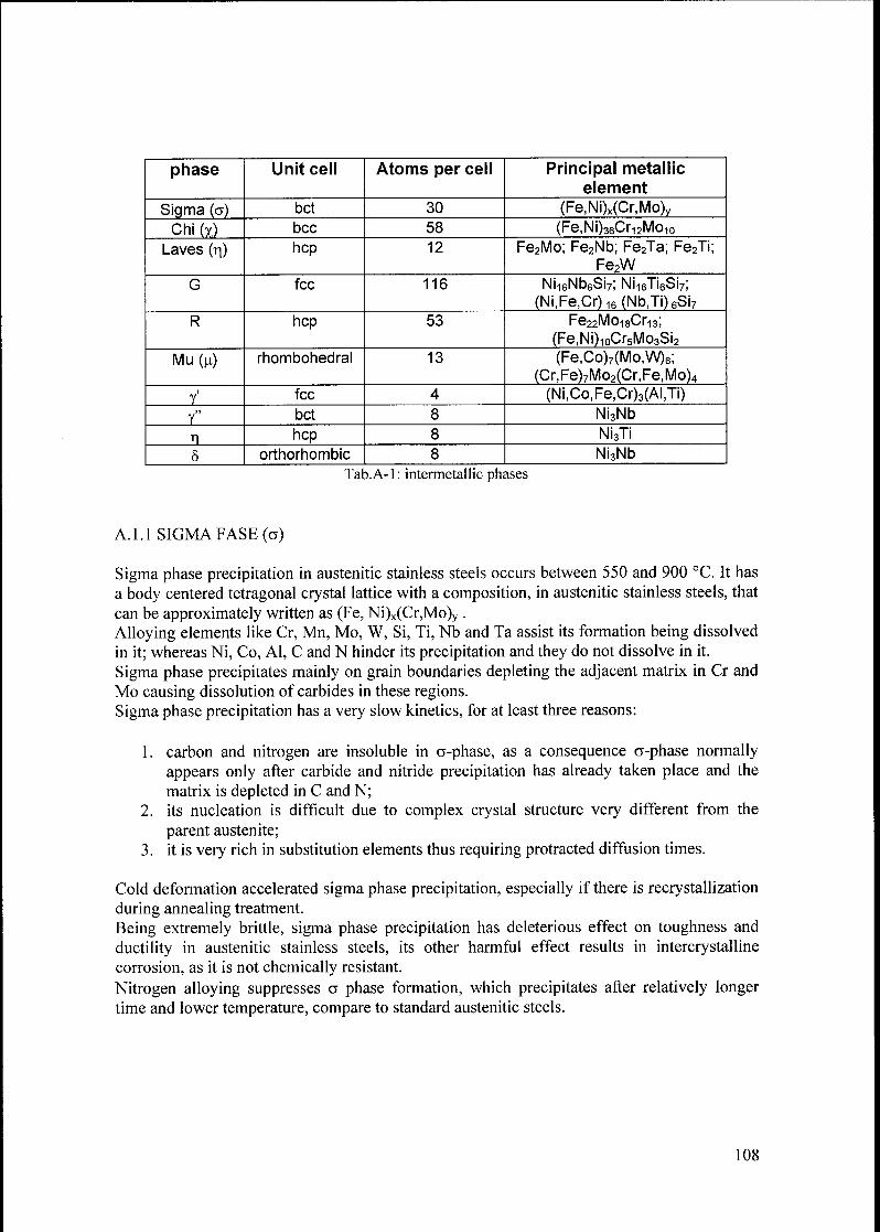
phase Unit cell Atoms per cell Principal metallic
element
Sigma (a) bet 30 (Fe,Ni)x(Cr,Mo)y
Chi (x) bec 58 (Fe,Ni)36Cri2Moio
Laves (ri) hep 12 Fe2Mo; Fe2Nb; Fe2Ta; Fe2Ti;
Fe2W
G fee 116 Ni16Nb6Si7; Ni16Ti6Si7;
(Ni,Fe,Cr)16(Nb,Ti)6Si7
R hep 53 Fe22Mo18Cr13;
(Fe,Ni)10Cr5Mo3Si2
Mu(u) rhombohedral 13 (Fe,Co)7(Mo,W)6;(Cr, Fe)7Mo2(Cr, Fe, Mo)4
>
Y fec 4 (Ni,Co,Fe,Cr)3(AI,Ti)n
Y bet 8 Ni3Nb
ri hep 8 Ni3Ti
5 orthorhombic 8 Ni3Nb
Tab.A-1: intermetallic phases
A. 1.1 SIGMA FASE (a)
Sigma phase precipitation in austenitic stainless steels occurs between 550 and 900 °C. It has
a body centered tetragonal crystal lattice with a composition, in austenitic stainless steels, that
can be approximately written as (Fe, Ni)x(Cr,Mo)y .
Alloying elements like Cr, Mn, Mo, W, Si, Ti, Nb and Ta assist its formation being dissolved
in it; whereas Ni, Co, Al, C and N hinder its precipitation and they do not dissolve in it.
Sigma phase precipitates mainly on grain boundaries depleting the adjacent matrix in Cr and
Mo causing dissolution of carbides in these regions.
Sigma phase precipitation has a very slow kinetics, for at least three reasons:
1. carbon and nitrogen are insoluble in a-phase, as a consequence rj-phase normally
appears only after carbide and nitride precipitation has already taken place and the
matrix is depleted in C and N;
2. its nucleation is difficult due to complex crystal structure very different from the
parent austenite;3. it is very rich in substitution elements thus requiring protracted diffusion times.
Cold deformation accelerated sigma phase precipitation, especially if there is recrystallization
during annealing treatment.
Being extremely brittle, sigma phase precipitation has deleterious effect on toughness and
ductility in austenitic stainless steels, its other harmful effect results in intercrystalline
corrosion, as it is not chemically resistant.
Nitrogen alloying suppresses a phase formation, which precipitates after relatively longertime and lower temperature, compare to standard austenitic steels.
108

A. 1.2. CHI PHASE (x)
The x-phase is a carbon-dissolving compound that can be interpreted either as an intermetallic
phase or as carbide MigC. It has a bcc a-Mn type crystal structure.
Precipitation can only occur if Mo or/and Ti is present, x-phase is found mainly on the grainboundaries, incoherent twin boundaries, coherent twin boundaries and on dislocation within
the matrix, x-phase precedes a-phase formation and cold working accelerates its nucleation.
Nitrogen alloying shifts % phase precipitation to longer time and reduces the temperature
range for precipitation.
MôC carbide tends to appear instead of the % phase with increasing nitrogen content.
A. 1.3. LAVES PHASE (ti)
Laves phases in austenitic stainless steels have hexagonal close packed structure of MgZn2
type. The most common are Fe2Mo, Fe2Nb and Fe2Ti, or a combination of all three, for
example, Fd (Mo,Ni,Ti).The Fe2Nb Laves phase precipitation can cause significant precipitation hardening in
austenitic stainless steels with high amount ofNb.
Laves phases precipitation occurs along grain boundaries, incoherent and coherent twin
boundaries and within the grain.In high nitrogen austenitic stainless steels with Mo r| phase precipitation is shifted to higher
temperature and it is accelerated by nitrogen.
A.2. CARBIDES PRECIPITATION
Carbon content in wrought austenitic stainless steels is usually between 0.05+0.25 weight
percent, depending on the steel grades [ASM94].Carbon solubility in austenite decreases rapidly as the temperature decreases and high Ni
content furthermore reduces it, as consequence precipitation of M23C6 carbide, where M
represents Cr, Fe, Mo and Ni, is a very common phenomenon.The addition of "stabilizing elements" such as Ti, Nb and V decreases the carbon solubilityeven further resulting in MC type carbides, where M represents Ti, Nb and/or V. The
presence of Mo in certain alloys can cause the precipitation of ri-type carbide MôC, where M
represents Fe, Mo and Cr.
Tab A-2 summarized results concerning crystal structures and compositions of carbides which
may appear in austenitic stainless steels.
Carbides Unit cell Atoms per cell Principal metallic element
M23C6 fee 116 Cr, Fe, Mo, Ni
MC ord fee 8 Ti.Nb.V and/or Zr
M6C fee 112 Fe, Mo, Cr
M7C3 hep 40 Cr, Fe
Tab.A-2: carbides
109
A.2.1.M23C6 CARBIDES
M23C6 is the main carbide that may precipitate in austenitic steels. It has fee structure and Fe,Mo and Ni can substitute for Cr. The M23C6 carbide is normally undesirable since its presenceis associated with sensitisation or intergranular corrosion by depletion in chromium content at
grain boundaries, where it mainly precipitates, as well as a decrease in ductility and
toughness.
Nitrogen alloying inhibits M23C6 precipitation.M23C6 carbide is normally the first phase that may form in austenitic stainless steels.
Depending on carbon content significant amount of carbides can form after only few minutes
between 650 and 750°C.
In the case of stabilized steels M23C6 dissolution takes place due to precipitation of the more
stable MC carbides.
In non-stabilized steels M23C6 dissolution may also occur if there is significant precipitationsof intermetallic phases such as a phase, x phase and Laves phase. Intermetallic phasesprecipitation lower the Cr and Mo content of the matrix increasing carbon solubility and
leading to partial dissolution of the M23C6 carbide.
In high nitrogen austenitic stainless steels nitrogen shifts M23C6 precipitation to longer times
due to a retardation of M23C6 nucleation because this carbides does not contain nitrogen.
A.2.2. MC CARBIDES
The MC (M = Ti, Zr, Hf, V, Nb and Ta) carbides are very stable and are present in stabilized
austenitic stainless steels such as AISI 321 (Ti stabilized), AISI 347 and 348 (Nb stabilized).Addition of strong MC carbides former elements hinders M23C6 precipitation. However Ti, Zr
or Hf addition results, unavoidably, in formation of MN nitrides and M4C2S2 carbosulphidesthat are even more stable than the MC carbide.
MC carbides having fee lattice are formed in austenitic CrNi steels containing Ti or Nb. Theyreduce the carbon content in the matrix and prevent M23C6 precipitation. Along with a
stabilising effect, their precipitation can be used for strengthening.Nitrogen can partially substitute for carbon in these carbides. They are referred to as
carbonitrides M(C,N) existing in a wide range of interstitial contents.
The MC carbide precipitation is predominantly intergranular, on dislocations and stackingfault however MC precipitation at grain boundaries can also occur.
A.2.3. M6C CARBIDES
The carbides of the type MôC (M = Fe, Cr, Mo, W, Nb and V), also known as rj-carbide, are
often found in austenitic stainless steels containing Mo, W and Nb. They contain more than
one metallic element, requiring the presence of at least three types of atoms and usuallyrepresented by the formulae A3B3C or A4B2C (i.e. Fe3Mo3C in Mo containing steels).This type of carbide has fee, diamond type, structure.
Nitrogen additions favour MôC precipitation instead of the detrimental M23C6, because the
former is able to dissolve more nitrogen than the latter. Nitrogen atoms replace carbon atoms
in the lattice.
110

This type or carbide is very common in superastenitic stainless steels due their high Mocontent (> 6wt%).
A.3. NITRIDES
Nitrides in austenitic stainless steels can be grouped in two classes:
1. primary nitrides of type MN (M = Zr, Ti, Nb and V) formed in stabilized steels
containing residual amounts of nitrogen (< 0.1wt%);2. secondary nitrides of the type M2N (M = Cr, Fe) formed in stainless steels containing
high levels of nitrogen (> 0.1wt%).
Tab A-3 summarized results concerning crystal structures and compositions of nitrides which
may appear in austenitic stainless steels.
Nitrides Unit cell Atoms per cell Principal metallic element
MN Ord fee 8 ZrN; TiN; NbN; VN
M2N hep 9 (Cr,Fe)2NZ- phase tetragonal 6 CrNNb
Tab.A-3: nitrides
A.3.1 PRIMARY NITRIDES MN
The MN nitrides have the same crystalline structure as MC carbides but they are even more
stable and do not dissolve during solution annealing.They can dissolve small amounts of other metallic elements present in the matrix such as Fe,Cr and Ni, but only very small amounts of C.
Chromium nitride precipitation in austenitic stainless steels with low levels of nitrogen (lessthan 0.1 wt%) usually occurs in continuous mode on grain boundaries, inside the grains and on
dislocations.
A.3.2 SECONDARY NITRIDES M2N
In high nitrogen austenitic stainless steels (Cr,Fe)2N type nitrides form below 1000°C, with an
hexagonal closed packet lattice (hep s-nitride); discontinue precipitation is common observed
giving a cellular structure referred sometimes as "false perlite" [Sim96]. Nitrogen depletion in
the matrix due to nitrides precipitation can make austenite unstable and formation of ferrite
and sigma phase is possible. Furthermore (Cr,Fe)2N precipitation has adverse effect on
toughness and on the corrosion resistance of austenitic stainless steels.
Nitrogen in solid solution delays the precipitation of phases, which do not dissolve or at least
in very small quantity nitrogen, such as M23C6, a, % and Laves phase.In stainless steels containing Nb and more than 0.4% nitrogen, precipitation of Z phase can
occur. Z phase is a nitride, with a tetragonal lattice structure, which contain Cr, Mo, Nb; it
forms on grain boundaries and within grains with different morphologies.
Ill
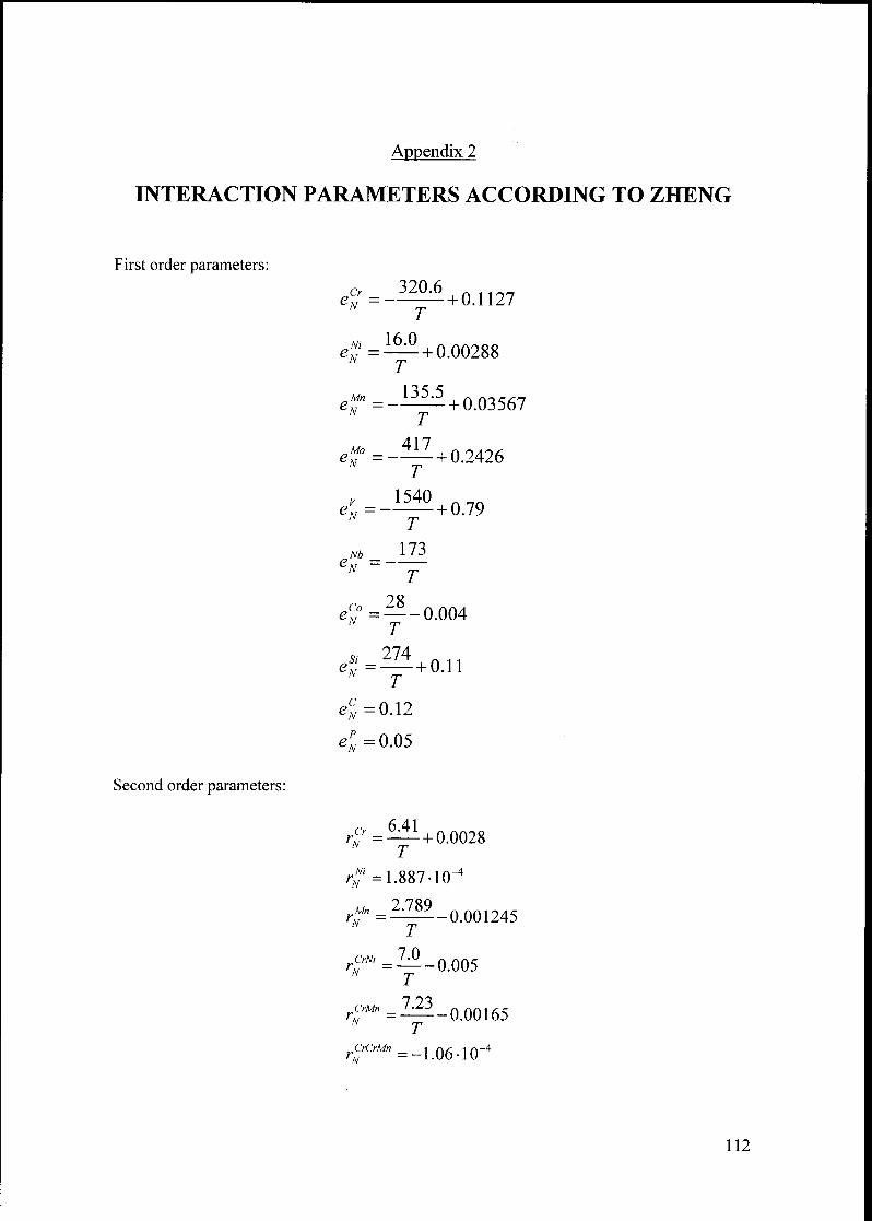
Appendix 2
INTERACTION PARAMETERS ACCORDING TO ZHENG
First order parameters:
eCr = —320.6
+ 0.1127
eNl =
Mn
16.0+ 0.00288
135.5
T
All
+ 0.03567
ef=-^i- +0.2426T
el-IJtl
T
- + 0.79
tf173
T
ec° = --0.004T
ti-274
= +
T0.11
eS-= 0.12
eFN-= 0.05
Second order parameters:
6 41
//=—+0.0028
r*= 1.887-10"*
r' =^-0.005r^rMn=—-0.00165
CrCrMn
rN -1.06-10"
112
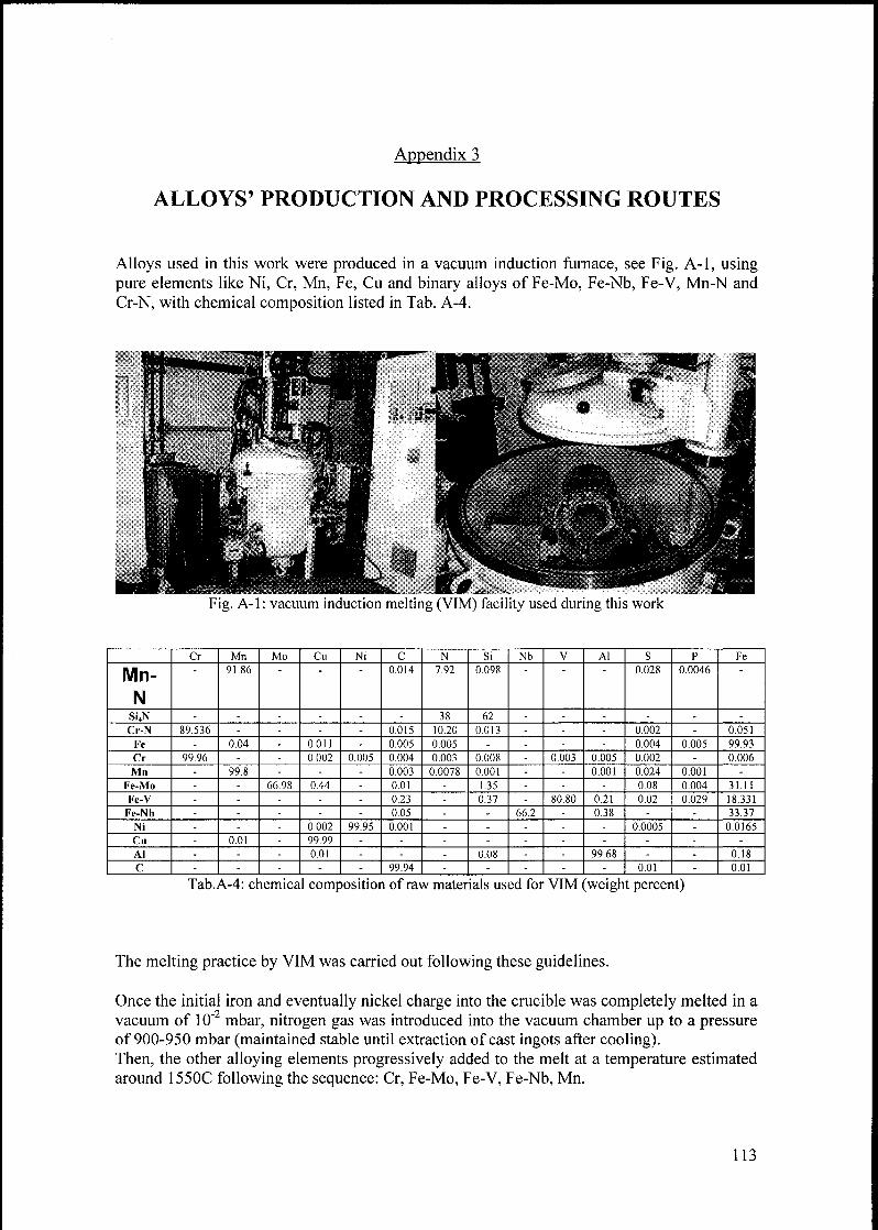
Appendix 3
ALLOYS' PRODUCTION AND PROCESSING ROUTES
Alloys used in this work were produced in a vacuum induction furnace, see Fig. A-1, using
pure elements like Ni, Cr, Mn, Fe, Cu and binary alloys of Fe-Mo, Fe-Nb, Fe-V, Mn-N and
Cr-N, with chemical composition listed in Tab. A-4.
Fig. A-1 : vacuum induction melting (VIM) facility used during this work
Cr Mn Mo Cu Ni C N Si Nb V Al S p Fe
Mn-
N
91 86 0014 7 92 0 098 0.028 0.0046
SijN - - - - - - 38 62 - - - - - -
Cr-N 89 536 - - - - 0015 10.20 0013 - - - 0.002 - 0.051
Fe - 0.04 - 0011 - 0 005 0 005 - - - - 0.004 0 005 99.93
Cr 99 96 - - 0 002 0 005 0 004 0 003 0 008 - 0 003 0.005 0.002 - 0.006
Mn - 99.8 - - - 0 003 0.0078 0 001 - - 0.001 0 024 0.001 -
Fe-Mo - - 66 98 0 44 - 0.01 - 1 35 - - - 0.08 0.004 31.11
Fe-V - - - - - 0 23 - 0 37 - 80 80 021 0.02 0 029 18.331
Fe-Nb - - - - - 0 05 - - 66.2 - 0 38 - - 33.37
Ni - - - 0 002 99.95 0 001 - - - - - 0 0005 - 0 0165
Cu - 0.01 - 99 99 - - - - - - - - - -
Al - - - 001 - - - 0 08 - - 99 68 - - 0.18
C - - - - - 99.94 - - - - - 0.01 - 0 01
Tab.A-4: chemical composition of raw materials used for VIM (weight percent)
The melting practice by VIM was carried out following these guidelines.
Once the initial iron and eventually nickel charge into the crucible was completely melted in a
vacuum of 10~2 mbar, nitrogen gas was introduced into the vacuum chamber up to a pressure
of 900-950 mbar (maintained stable until extraction of cast ingots after cooling).Then, the other alloying elements progressively added to the melt at a temperature estimated
around 1550C following the sequence: Cr, Fe-Mo, Fe-V, Fe-Nb, Mn.
113

When complete dissolution of all raw materials occurred, 20g of CaSi together 5g of
aluminum foil were added as a deoxidizing medium. After a couple of minutes power was
decreased to reach a liquid temperature in the range 1450-1460C before the addition of C, Cu,
Cr2N in this order.
Nitrogen solubility in the liquid phase is strongly affected by the bath temperature, namely it
decreases with increasing the liquid temperate, and hence in order to avoid nitrogen escape
from the melt during QyN addition, the liquid temperature should be the lowest possible. A
good compromise between bath fluidity and nitrogen solubility was achieved at 1450-1460 °C
(lower temperatures gave arise to solidification around the crucible's walls).
Casting was performed pouring the liquid metal into cold steel cylinders with a copper plateon the bottom. To accelerate nitrogen take up chromium nitrides were added slowly to the
melt (alloy composition of course take also in consideration the chromium contained in the
added nitrides). After cooling an ingot of about lOKg weight with a diameter of 85 mm was
extracted from the furnace. For some experiments three smaller ingots of about 3 kg weightswith a diameter of 45 mm were cast.
All the ingots were subsequently homogenized in an electric furnace in air, with a
combination of temperature and time depending upon alloy composition before hot forging,
necessary to modify the coarse microstructure resulting from casting into a more uniform with
homogenous grains.Hot forging was carried out by the company Burgher & Co (Schafisheim-AG, Switzerland)with a hammer machine between 1100 and 1200 °C, in order to obtain plates with a
rectangular cross section of approximately 70mm x 17mm (if not otherwise specified), See
Fig. A-2.
Ingots were heated up to forging temperature in an oven (gas furnace) and water quenchedafter forging.
Fig.A-2: two different phases during hot forging of alloys developed in this work.
114
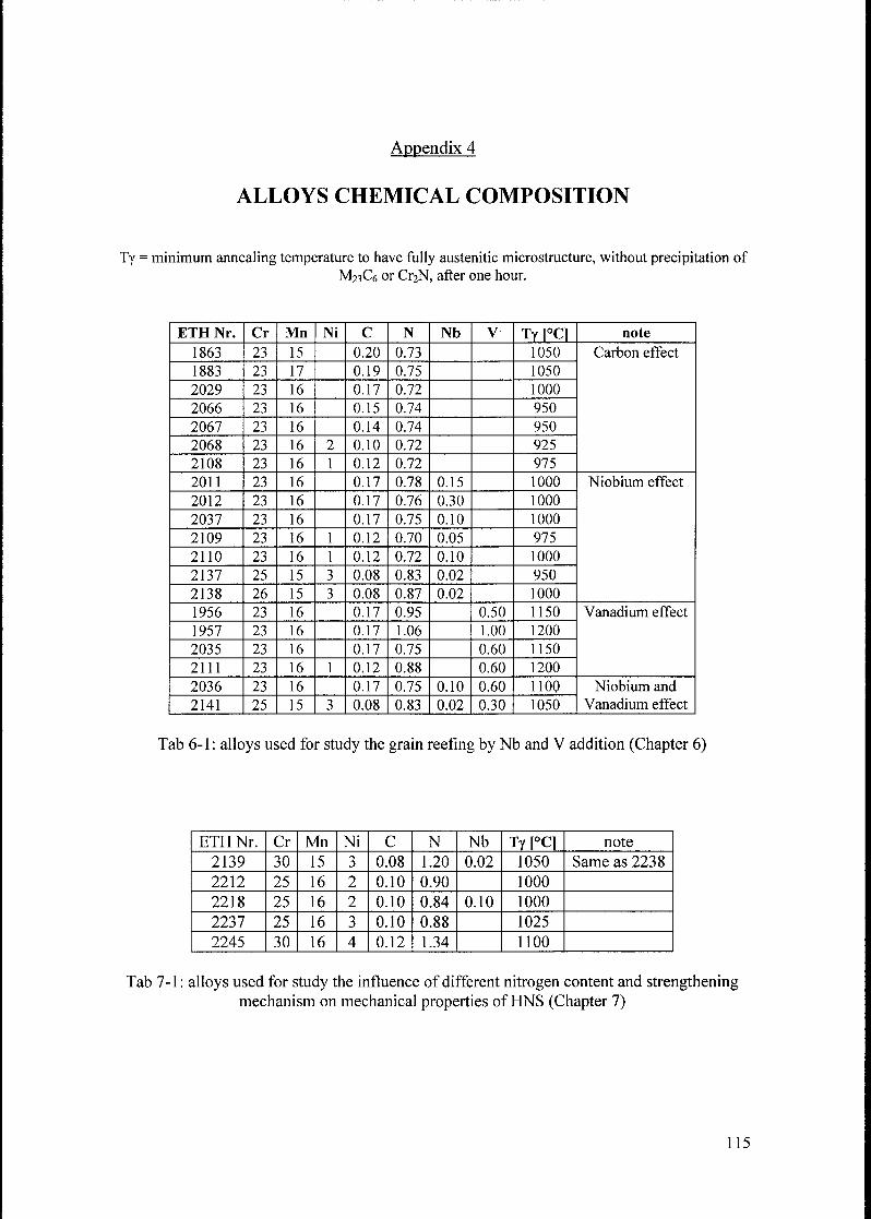
Appendix 4
ALLOYS CHEMICAL COMPOSITION
Ty = minimum annealing temperature to have fully austenitic microstructure, without precipitation of
M23C6 or Cr2N, after one hour.
ETH Nr. Cr Mn Ni C N Nb V Ty [°C1 note
1863 23 15 0.20 0.73 1050 Carbon effect
1883 23 17 0.19 0.75 1050
2029 23 16 0.17 0.72 1000
2066 23 16 0.15 0.74 950
2067 23 16 0.14 0.74 950
2068 23 16 2 0.10 0.72 925
2108 23 16 1 0.12 0.72 975
2011 23 16 0.17 0.78 0.15 1000 Niobium effect
2012 23 16 0.17 0.76 0.30 1000
2037 23 16 0.17 0.75 0.10 1000
2109 23 16 1 0.12 0.70 0.05 975
2110 23 16 1 0.12 0.72 0.10 1000
2137 25 15 3 0.08 0.83 0.02 950
2138 26 15 3 0.08 0.87 0.02 1000
1956 23 16 0.17 0.95 0.50 1150 Vanadium effect
1957 23 16 0.17 1.06 1.00 1200
2035 23 16 0.17 0.75 0.60 1150
2111 23 16 1 0.12 0.88 0.60 1200
2036 23 16 0.17 0.75 0.10 0.60 1100 Niobium and
Vanadium effect2141 25 15 3 0.08 0.83 0.02 0.30 1050
Tab 6-1 : alloys used for study the grain reefing by Nb and V addition (Chapter 6)
ETH Nr. Cr Mn Ni C N Nb Ty [°C] note
2139 30 15 3 0.08 1.20 0.02 1050 Same as 2238
2212 25 16 2 0.10 0.90 1000
2218 25 16 2 0.10 0.84 0.10 1000
2237 25 16 3 0.10 0.88 1025
2245 30 16 4 0.12 1.34 1100
Tab 7-1 : alloys used for study the influence of different nitrogen content and strengtheningmechanism on mechanical properties of HNS (Chapter 7)
115
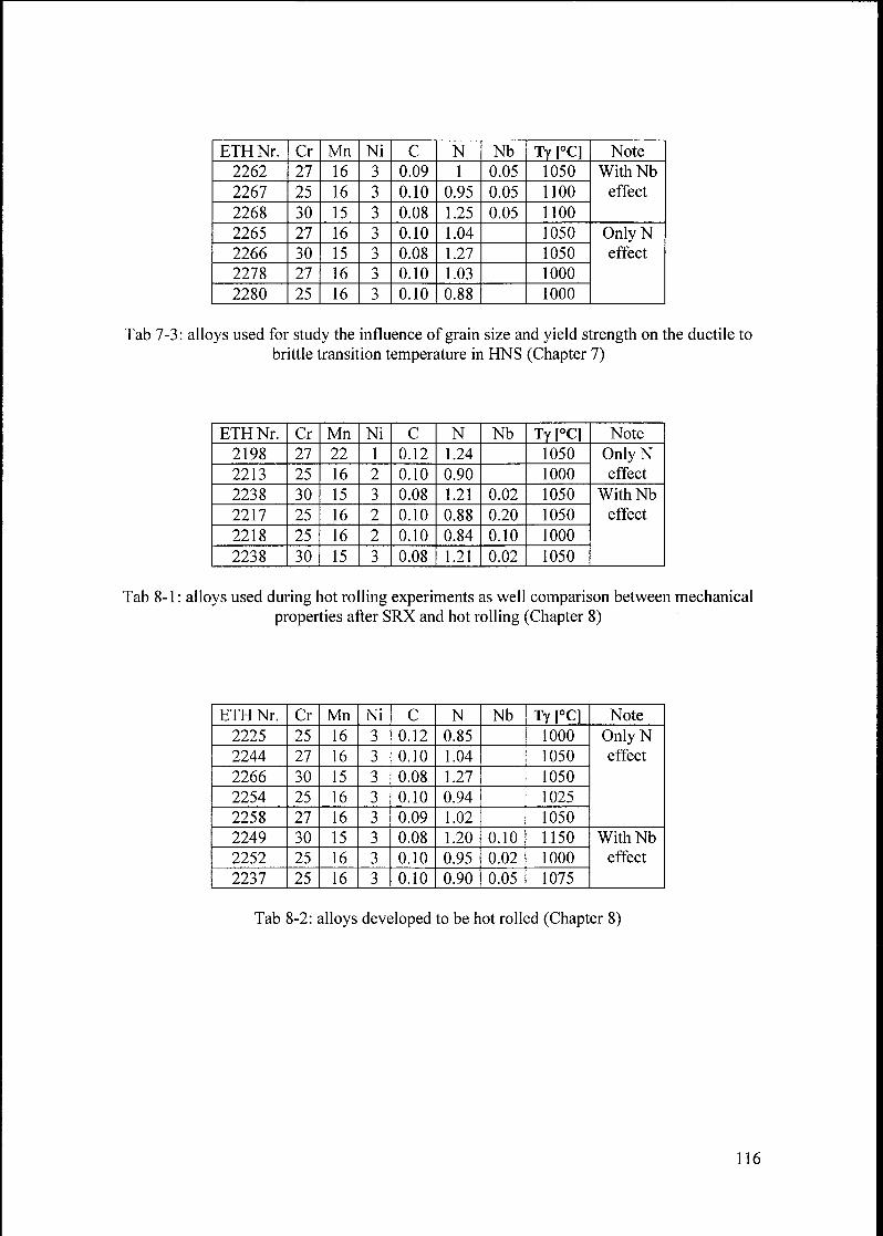
ETH Nr. Cr Mn Ni C N Nb Ty [°C] Note
2262 27 16 3 0.09 1 0.05 1050 WithNb
effect2267 25 16 3 0.10 0.95 0.05 1100
2268 30 15 3 0.08 1.25 0.05 1100
2265 27 16 3 0.10 1.04 1050 OnlyNeffect2266 30 15 3 0.08 1.27 1050
2278 27 16 3 0.10 1.03 1000
2280 25 16 3 0.10 0.88 1000
Tab 7-3: alloys used for study the influence of grain size and yield strength on the ductile to
brittle transition temperature in HNS (Chapter 7)
ETHNr. Cr Mn Ni C N Nb Ty [°C] Note
2198 27 22 1 0.12 1.24 1050 OnlyNeffect2213 25 16 2 0.10 0.90 1000
2238 30 15 3 0.08 1.21 0.02 1050 With Nb
effect2217 25 16 2 0.10 0.88 0.20 1050
2218 25 16 2 0.10 0.84 0.10 1000
2238 30 15 3 0.08 1.21 0.02 1050
Tab 8-1 : alloys used during hot rolling experiments as well comparison between mechanical
properties after SRX and hot rolling (Chapter 8)
ETHNr. Cr Mn Ni C N Nb Ty [°C] Note
2225 25 16 3 0.12 0.85 1000 OnlyNeffect2244 27 16 3 0.10 1.04 1050
2266 30 15 3 0.08 1.27 1050
2254 25 16 3 0.10 0.94 1025
2258 27 16 3 0.09 1.02 1050
2249 30 15 3 0.08 1.20 0.10 1150 WithNb
effect2252 25 16 3 0.10 0.95 0.02 1000
2237 25 16 3 0.10 0.90 0.05 1075
Tab 8-2: alloys developed to be hot rolled (Chapter 8)
116
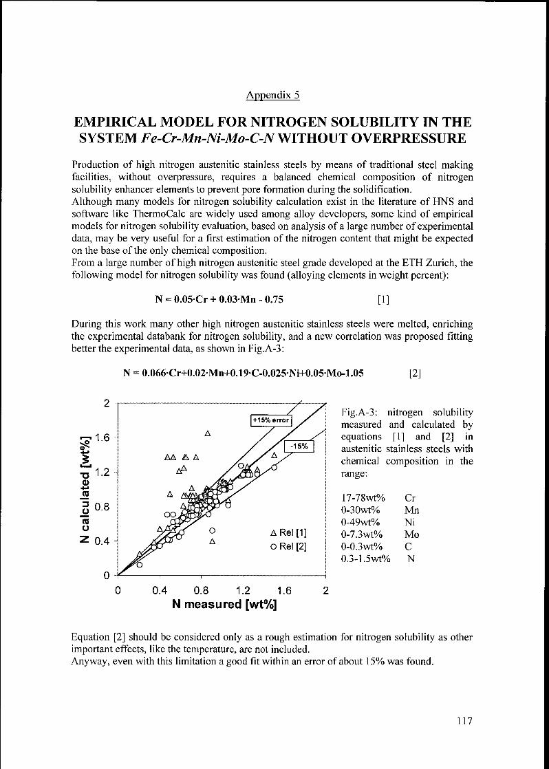
Appendix 5
EMPIRICAL MODEL FOR NITROGEN SOLUBILITY IN THE
SYSTEM Fe-Cr-Mn-Ni-Mo-C-NWITHOUT OVERPRESSURE
Production of high nitrogen austenitic stainless steels by means of traditional steel makingfacilities, without overpressure, requires a balanced chemical composition of nitrogensolubility enhancer elements to prevent pore formation during the solidification.
Although many models for nitrogen solubility calculation exist in the literature of HNS and
software like ThermoCalc are widely used among alloy developers, some kind of empiricalmodels for nitrogen solubility evaluation, based on analysis of a large number of experimentaldata, may be very useful for a first estimation of the nitrogen content that might be expectedon the base of the only chemical composition.From a large number of high nitrogen austenitic steel grade developed at the ETH Zurich, the
following model for nitrogen solubility was found (alloying elements in weight percent):
N = 0.05-Cr + 0.03-Mn - 0.75 [ 1 ]
During this work many other high nitrogen austenitic stainless steels were melted, enrichingthe experimental databank for nitrogen solubility, and a new correlation was proposed fittingbetter the experimental data, as shown in Fig.A-3:
N = 0.066Cr+0.02Mn+0.19C-0.025Ni+0.05Mo-1.05 [2]
Fig.A-3: nitrogen solubilitymeasured and calculated byequations [1] and [2] in
austenitic stainless steels with
chemical composition in the
range:
17-78wt% Cr
0-30wt% Mn
0-49wt% Ni
0-7.3wt% Mo
0-0.3wt% C
0.3-1.5wt% N
0 0.4 0.8 1.2 1.6 2
N measured [wt%]
Equation [2] should be considered only as a rough estimation for nitrogen solubility as other
important effects, like the temperature, are not included.
Anyway, even with this limitation a good fit within an error of about 15% was found.
ARel[1]
o Rel [2]
117
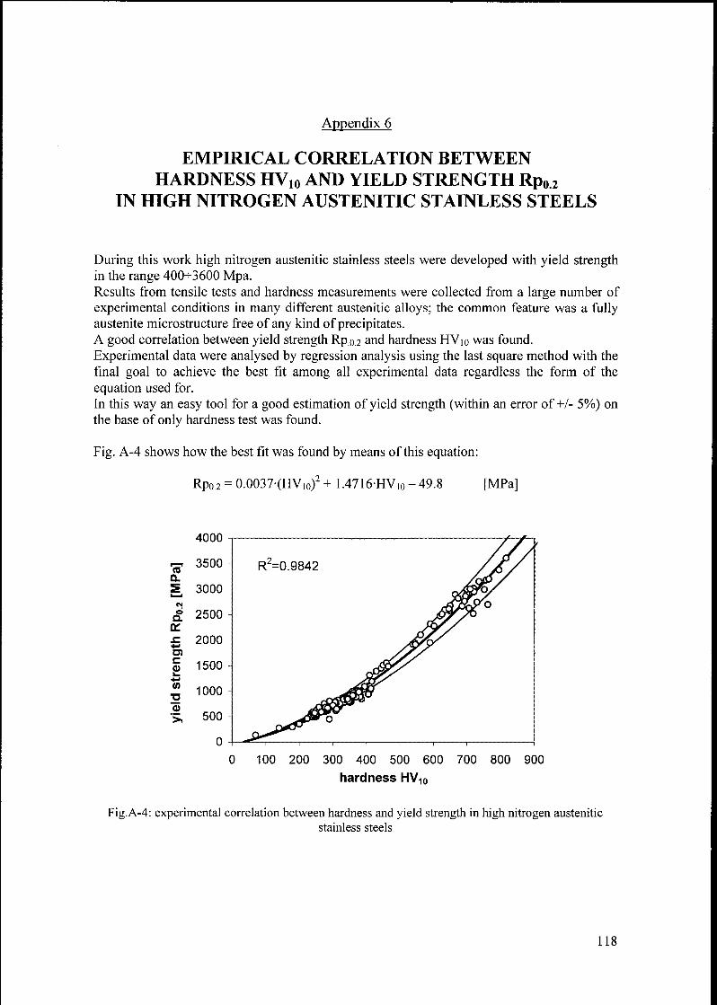
Appendix 6
EMPIRICAL CORRELATION BETWEEN
HARDNESS HV10 AND YIELD STRENGTH Rp02IN HIGH NITROGEN AUSTENITIC STAINLESS STEELS
During this work high nitrogen austenitic stainless steels were developed with yield strengthin the range 400-3600 Mpa.Results from tensile tests and hardness measurements were collected from a large number of
experimental conditions in many different austenitic alloys; the common feature was a fullyaustenite microstructure free of any kind of precipitates.A good correlation between yield strength Rp.0.2 and hardness HV10 was found.
Experimental data were analysed by regression analysis using the last square method with the
final goal to achieve the best fit among all experimental data regardless the form of the
equation used for.
In this way an easy tool for a good estimation of yield strength (within an error of+/- 5%) on
the base of only hardness test was found.
Fig. A-4 shows how the best fit was found by means of this equation:
Rpo.2 = 0.0037-(HV,o)2 + 1.4716-HV,0 - 49.8 [MPa]
tuuu-
p-. 3500 R2=0.9842Q.
2 3000 - q/sÈf>/
RP0.2 Ol OOj&jPçgO
£ 2000 -
S 1500 -
4->
yields
en
0
0
0
0
0
r^*d^®0 ^BETm,, , , 1
__
I I I
100 200 300 400 500 600 700 800 900
hardness HV10
Fig.A-4: experimental correlation between hardness and yield strength in high nitrogen austenitic
stainless steels
118
REFERENCES
[Ashby70] Ashby M.: The deformation ofplastically non homogeneous materials; Phil.
Mag. 21: 399-421
[ASM94] ASM Specialty handbook: Stainless Steels, 1994
[BleckOl] W. Bleck, c. Herzig and U. Lorenz: A method ofproducing very fine ferritegrains by means ofhotforming; Steel Research 72 (2001) No. 10, pp 406-411
[Byrn87] M.L.G. Byrnes, M. Grujicic, W.S. Owen: Nitrogen Strengthening ofa Stable
Austenitic Stainless Steels; Acta Metall. 35, (7), 1853-1862 1987
[ChoOl] S.H. Cho, K.B. Kang and J. Jonas: The Dynamic, Static and MetadynamicRecrystallization ofNb-microalloyed Steel; ISIJ International, Vol. 41 (2001),
No.l,pp 63-69
[Cott98] J.A. Cotton, R.D. Knutsen and C.I. Lang: The Influence ofniobium andvanadium on the Microstructure and Mechanicalproperties ofa HighNitrogen Stainless Steels; Material Science Forum Vols. 318-320 (1999) pp.
271-280
[Cun02] P.J. Cunat and T. Pauly: Stainless Steel as a Competitor to Light MaterialforBuilding and Automotive Applications; 4th European Stainless Steel Science
and market Congress - Paris 2002
[Feich91] H. K. Feichtinger: Alternative methods for the production of high nitrogen
steels; Proceedings of International Conference on Stainless Steels, 1991,
Chiba, ISIJ
[Feich99] H.K. Feichtinger and G. Stein: Melting ofHigh Nitrogen Steels; Material
Science Forum Vols. 318-320 (1999) pp. 261-270
[Fleisch64] R.L. Fleischer: The strengthening ofmetals; D. Peckner ed., BY, Reinhold
pub., 93, 1964
[Gav88] V.G. Gavriljuk, V.A. Duz and S.P. Jephimenko: Dislocations in austenite and
mechanical properties of high nitrogen steel; in "High Nitrogen Steels", Eds.
Foct J.F., Hendry A., The Institute of Metals, London, 1989s, pp. 447
[Gav96] V.G. Gavriljuk: Nitrogen in Iron and Steel; ISIJ International, Vol. 36 1996),No. 7, pp 738-745
[Gav99] V.G. Gavriljuk and H. Berns: High Nitrogen Steels: Structure, Properties,Manufacture, Aapplications; Springer, 1999
[Haas76] P. Haasen: Dislocation in Solids; chapter 15, North Holland, New York,
1976,155
[Hannes02] Hannes J.C. Speidel: Development of Chromium based, high nitrogen, highstrength, alloys with face centred cubic crystal lattices; Diss.-Thesis ETH-Nr.
14888, 2002
[Hänn99] H. Hänninen: Corrosion properties ofHNS; Material Science Forum Vols.
318-320 (1999) pp. 479-788
[Honey81] R.W.K. Honeycombe: Steels; microstructure andproperties; 1981, Edward
Arnold
[Igle02] J. Iglesias, L. Bernardez and E. Andres: The Intelligent Use ofStainless Steel
reinforcement Bars; 4l European Stainless Steel Science and market Congress- Paris 2002
119
[Ike96] Yuji Ikegami and Rikio Nemoto: Effect of Thermo Mechanical Treatment on
Mechanical Properties of High Nitrogen Containing Cr-Mn-Ni Austenitic
Stainless Steels; ISIJ International Vol. 36 (1996), No.7, pp. 855-961
[Karj96] L.P. Karjalainen and J. Perttula: Characteristic of static and MetadynamicRecrystallization and Strain accumulation in Hot deformed Austenite as
revealed by the Stress Relaxation Method; ISIJ International, Vol. 36 (1996),No. 6, pp 729-736
[Kim96] Y.H. Kim, Y.Y. Lee and Y.D. Lee: Effect ofN and S on the hot ductility of
high nitrogen 18Cr 8Ni stainless Steels; Proceeding of International CongressStainless Steels '96, Duesseldorf, Germany, 1996, 337-338
[Kim02] Y.H. Kim, K.Y. Kim and Y.D. Lee: High Strength, Nitrogen-alloyedAustenitic Stainless Steel for Automotive Applications; 4l European Stainless
Steel Science and market Congress - Paris 2002
[KowOO] C. Kowanda: Stickstofflöslichkeit in Nickel und Nickelbasislegierungen im
schmelzflüssigen Zustand unter erhöhtem Stickstoffpartialdruck; Diss.-Thesis
ETH-Nr. 13860,2000
[Kunz94] J. Kunze and I. Rothe: Solubility ofNitrogen in FeCrMn Alloys; Steel research
65,No.8, 1994,pp331[Li70] Li J.C.M. and Chou Y.T.: The role ofdislocations in theflow stress grain size
relationships; Metall Trans 1(5): 1145-1159
[Lilj72] L.G. Liljestrand: Structure and internal stress after hot deformation in an
austenitic stainless steels with different carbon and nitrogen content; Scand. J.
Metall.,Vol. 1, 1972, pp.271-277
[Menz96] J. Menzel, W. Kirschner and G. Stein: High nitrogen containing Ni-freeaustenitic steelsfor medical applications; ISIJ International Vol.36 (1996),No.7, pp 893-900
[MU1193] P. Müllner, C. Solenthaler, P. uggowitzer and M.O. Speidel: On the effect of
nitrogen on the dislocation structure of austenitic stainless steels; Materials
Science and Engineering, A164 (1993) 164-169
[MÜ1194] P. Müllner, C. Solenthaler, P. uggowitzer and M.O. Speidel: Brittlefracture in
austenitic steel; Acta Metall. Mater. Vol. 42, No.7, pp 2211-2217, 1994
[Müll94b] P. Müllner, C. Solenthaler and M.O. Speidel: Second order twinning in
austenitic steel; Acta Metal. Mater. Vol. 42, No.5, pp. 1727-1732, 1994
[Owen90] W.S. Owen: Nitrogen Strengthening of Austentitc Stainless Steels at
Temperature above 500K; Proceeding 2" Int. Conf. High Nitrogen Steels,
1990, Aachen (Germany), Stahl & Eisen, pp. 42
[Padi02] A.F. Padilha and P.R. Rios: Decomposition ofAustenite in Austenitic Stainless
Stels; ISIJ international, Vol. 42 (2002), No. 4, pp. 325-337
[Paul94] N. Paulus: Entwicklung von stickstofflegierten austenitischen Stählen höchster
festigkeit; Diss.-Thesis ETH-Nr. 10899, 1994
[Proc89] Proc. Of the International Conference on Stainless Steels, INCOSS 89,
Bombay, 1989
[Rapa41] Rapatz F.: Stahl und Eisen; 1941, B 61, H 46, 1073-78
[Reed88] R.P. Reed and N.J. Simon: Nitrogen strengthening ofaustenitic stainless steels
at low temperatures; in "High Nitrogen Steels", Eds. Foct J.F., Hendry A., The
Institute of Metals, London, 1989s, pp. 180
[Sama38] Samarin A. M. et. al., Metallurg, 1938, 11(107), 80-3
120
[Sas89] J. Sassen, A.J. Garratt-Reed and W.O. Owen: Electron microscopy ofaustenitic Fe-Ni-Cr alloys; in "High Nitrogen Steels", Eds. Foct J.F., HendryA., The Institute of Metals, London, 1989s, pp. 159-162.
[Shan02] B.D. Shanina, V.G. Gavriljuk, H. Berns and F. Schmalt: Concept ofa new highstrength austenitic stainless steels; Steel research, 73, 2002, No.3
[Scher42] Sherer R. And H. Kessuew: Stahl und Eisen, 1942, Bd 22, 17, 347-52
[Schi02] A. di Schino and J.M. Kenny: Grain refining by martensitic reversion in the
AISI 304 stainless steel: effect on the mechanical properties; 4t EuropeanStainless Steel Science and market Congress - Paris 2002
[Schr75] R.E. Schramm and R.P. Reed: Met. Trans., 6A (1975), 1345.
[Schü67] E. Schürmann and H. Kunze, Giessereiforsschung 19, 1967
[Sim96] J.W. Simmons, B.S. Covino, J.A. Hawk and J.S. Dunning: Effect ofNitride
(Cr2N) Precipitation on the Mechanical, Corrosion, and wear Properties ofAustenitic Stainless Steels; ISIJ International Vol. 36, (1996), No. 7, pp. 846-
854
[Speid87] M.O. Speidel and P.J. Uggowitzer: High Manganese, High Nitrogen Austenitic
Stainless Steels: their strength and toughness; Proceedings High Manganese
High Nitrogen Austenitic Steels, Cincinnati, Ohio, USA 1987, Chicago,
Illinois, USA, 1992.
[Speid90] M.O. Speidel: Properties of High Nitrogen Steels; Proceeding 2nd Int. Conf.
High Nitrogen Steels, 1990, Aachen (Germany), Stahl & Eisen, pp. 128-131
[Speid91] M.O. Speidel: Corrosion Science ofstainless Steels; Proceedings of
International Conference on stainless Steels, 1991, Chiba, ISIJ, pp, 25
[SpeidOl] M.O. Speidel: Ultrahigh strength austenitic stainless steels; ProceedingsStainless Steel World 2001 Conference, The Hague - The Netherlands, 2001
[SpeidOlb] M.O. Speidel: Stainless Steel World Conference 2001, KCl Publishing ISBN
90-731 168 14 7
[Speid02] M.O. Speidel: Applications and Services; in High Nitrogen Austenitic Steel
and Stainless Steels, Kalpakkam 2002
[Speid03] M.O. Speidel: Nanogram size, high nitrogen austenitic stainless steels; Z.
Metallkunde, 2003
[Stein99] G. Stein, I. Hucklenbroich and M. Wagner: P2000 - a new austenitic high
nitrogen steelfor power generating equipment; Material Science Forum Vols.
318-320 (1999) pp. 167-174
[Stein99b] G. Stein, I. Hucklenbroich and H. Feichtinger: Current andfuture applicationsofhigh nitrogen steels; Material Science Forum Vols. 318-320 (1999) pp. 151-
160
[stral4] B. Strauss: Mikroscopische Stahluntersuchungen; Zeitschrift für angewandteChemie 27, (1914), pp633
[stra20] B. Strauss andE. Maurer: Die hochlegierten CrNi-Stähle als Nichtrostende
Stähle; Kruppsche Monatsheft 1 1920, ppl29
[TakaOl] S. Takaki, K. Kawasaki and Y. Kimura: Mechanical properties of ultra finegrained steels; Journal of Materials processing Technology, 117 (2002) 359-
363
[TendoOl] M. Tendo, y. Tadokoro, K. Suetsugu and T. Nakazawa: Effects ofNitrogen,Niobium and Molybdenum on Strengthening ofAustenitic Stainless Steel
Produced by Thermo-Mechanical Control Process; ISIJ international, Vol. 41
(2001), No.3,pp 262-267
121
[Tomo90] Y. Tomota and S. Endo, ISIJ International, 30 (1990), 656
[Uggo88] P.J. Uggowitzer and M. Harzenmoser: Strengthening of austenitic stainless
steels by nitrogen; in "High Nitrogen Steels", Eds. Foct J.F., Hendry A., The
Institute of Metals, London, 1989s, pp. 174
[Uggo91] P.J. Uggowitzer and M.O. Speidel: Ultrahigh strength Cr-Mn-NSteels;
Proceedings of International Conference on stainless Steels, 1991, Chiba, ISIJ,
p.762-769
[Uggo92] P.J. Uggowitzer, N. Paulus and M.O. Speidel: Ductile to brittle transition in
nitrogen alloyed austenitic stainless steels; Application of Stainless Steel 1992,
Stockholm, Sweden, 1992, ASM International, Vol.1, pp. 62-70
[Uggo92b] P.J. Uggowitzer: Festigkeit und Zähigkeit austenitischer Stickstoffstähle;Habilitationsschrift, ETH Zürich, 1992
[Uggo96] P.J. Uggowitzer, R. Magdowski and M.O. Speidel: Nickel Free High NitrogenAustenitic Steels; ISIJ International, Vol. 36 (1996), No. 7, pp. 901-908
[Vogt94] J.B. Vogt, A. Messai and J. Foct: Cleavagefracture ofaustenite induced by
nitrogen supersaturation; Scripta Metallurgica et Materialia, Vol. 31, No. 5,
pp. 549-554, 1994.
[Wang98] J. Wang: High Strength Nickel-free Duplex Stainless Steels for Structural
Engineering Applications; Diss.-Thesis ETH-Nr. 12649, 1998
[Wohlf98] H. Wohlfromm, P.J. Uggowitzer and M.O. Speidel: Panacea provides the
answer to Ni allergy; P.M. Special feature, Metal Powder report Vol. 53, Nr.9,
September 1998, pp 48-52
[Yama85] S. Yamamoto, T. Sakiyama and C. Ouchi: Effect of alloying Element on
recrystallization Kinetics after Hot deformation in Austenitic Stainless Steels;Transaction ISIJ, Vol. 27, 1987, pp 446-452
[Yama90] S. Yamamoto and Y. Kobayashi: Application of Thermo-Mechanical Control
process to Austenitic Stainless Steels; Recrystallization 90, Edited by T.
Chandra, The minerals, Metals & Materials society, 1990, pp. 169-174
[YongOl] Yong-Jun O.H., B.J. Lee, O. Yoo, B.S. Lee and J.H. Hong: PrecipitationBehaviour of carbonitrides in type 347 stainless Steels with various C and N
contents; Metallurgical and Materials Transactions A, Vol. 33A, 2002
[Yosh96] A. Yoshie, T. Fujita, M. Fujioka, K. Okamoto and H. Morikawa: Formulation
of the decrease in dislocation density of Deformed Austenite Due to Static
Recovery and Recrystallization; ISIJ International, Vol. 36 (1996), No.4, pp.
474-486
[Zhen91] X. H. Zheng: Nitrogen Solubility in Iron-Base Alloys and Powder Metallurgy
ofHigh Nitrogen Steels; Diss.-Thesis ETH-Nr. 9488, 1991
122
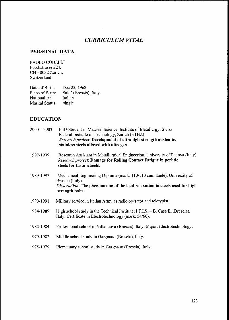
CURRICULUM VITAE
PERSONAL DATA
PAOLO COBELLI
Forchstrasse 224,
CH - 8032 Zurich,Switzerland
Date of Birth: Dec 25, 1968
Place ofBirth: Salo' (Brescia), Italy
Nationality: Italian
Marital Status: single
EDUCATION
2000 - 2003 PhD-Student in Material Science, Institute of Metallurgy, Swiss
Federal Institute of Technology, Zurich (ETHZ)Research project: Development of ultrahigh-strength austenitic
stainless steels alloyed with nitrogen
1997-1999 Research Assistant in Metallurgical Engineering, University of Padova (Italy).Research project: Damage for Rolling Contact Fatigue in perliticsteels for train wheels.
1989-1997 Mechanical Engineering Diploma (mark: 110/110 cum laude), University of
Brescia (Italy).Dissertation: The phenomenon of the load relaxation in steels used for high
strength bolts.
1990-1991 Military service in Italian Army as radio operator and teletypist
1984-1989 High school study in the Technical Institute: I.T.I.S. - B. Castelli (Brescia),
Italy. Certificate in Electrotechnology (mark: 54/60).
1982-1984 Professional school in Villanuova (Brescia), Italy. Major: Electrotechnology.
1979-1982 Middle school study in Gargnano (Brescia), Italy.
1975-1979 Elementary school study in Gargnano (Brescia), Italy.
123

WORKING EXPERIENCE
Jan 2000 - Jan 2003 Graduate Research Assistant/ Ph.D. at the Institute of Metallurgy,Swiss Federal Institute of Technology, Zurich (ETHZ), Switzerland
Jan 1999 - Dec 1999 Graduate Research Assistant at the Metallurgical Engineering
Department of Padova University (Italy).
Jan 1998 - Dec 1998 Graduate fellow (Academic Guest) at the Institute of Metallurgy, Swiss
Federal Institute of Technology, Zurich (ETHZ), Switzerland
Mar 1997 - Nov 1997 Graduate Research Assistant at the Mechanical Engineering
Department of Brescia University (Italy)
SKILLS
1. LANGUAGE
• Mother tongue Italian
• Fluently English• Basic knowledge German, French
2. SOFTWARE
Thermocalc: used for thermodynamic simulation in equilibrium, phase diagrams, others;
Word, Excel, Power Point, Corel Draw, Photoshop: for general purposes;
Basic, Pascal, LabView: basic knowledge of programming.
3. PRACTICAL
Operations with vacuum inductive furnace;Hot rolling and hot forging.
HOBBIES
Music, dancing, travelling, reading, airplanes and flight simulations on PC.
124