rigid coaxial transmission line - home - … · 1 5 august 2015.rev d2 17 march 2016.rev e...
TRANSCRIPT
1 5 August 2015.Rev D2 17 March 2016.Rev E
Dielectric LLC 22 Tower Road
Raymond, ME 04071 Phone: 800.341.9678
RIGID COAXIAL TRANSMISSION LINE
INSTRUCTION MANUAL

2 5 August 2015.Rev D2 17 March 2016.Rev E
INDEX
Considerations and Precautions…………………………Page 3 Transmission Line Do’s and Don’ts…………………….Page 4 General Components, Descriptions & Locations……….Page 5 Transmission Line Installation………………………….Page 6 Selecting Transmission Line Length……………………Page 6 Critical Frequencies……………………………………..Page 6 Length and VSWR Limit Tables………………………..Page 7-8 Hardware Torque Specifications………………………..Page 9 Hanger Specifications and Drawing…………………….Page 10 Loaded Length Charts …………………………………..Page 11-13 Horizontal Spring Hanger Drawing……………………..Page 14 digiTLine Special Instructions………………….………Page 15 digiTLine Set Tool Installation Drawing………….……Page 16

3 5 August 2015.Rev D2 17 March 2016.Rev E
VERTICAL RUN CONSIDERATIONS
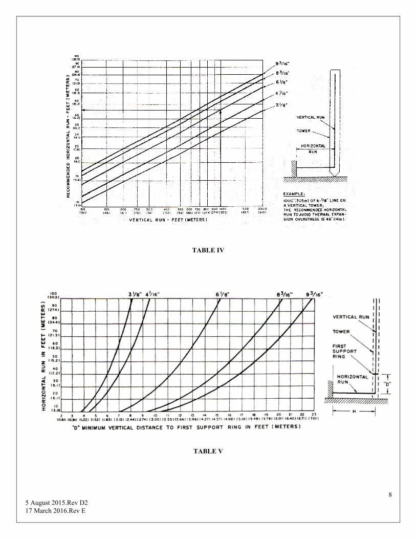
Provision must be made to accommodate the differential expansion between the cooper of the line and the steel of the tower. Temperature rise due to RF heating as well as ambient temperature changes must be taken into account. In the vertical run, this is accomplished by fixing the line at the tower top and “floating” it down the tower on spring hangers with expansion accumulating at the bottom of the tower. To accommodate this movement, the length of the horizontal run must be as specified in Table IV. In addition, the vertical run must be allowed to bend to accommodate movement in the horizontal run. This is assured by proper placement of the first vertical supporting as specified in Table V.
Generally, only standard lengths should be included in the vertical run except at the top where a field cut section is utilized. However, one or two special lengths may be inserted if it permits a better pattern of hangers. The position of flanges relative to hangers, guide rings and tower members must be carefully planned to avoid interference.
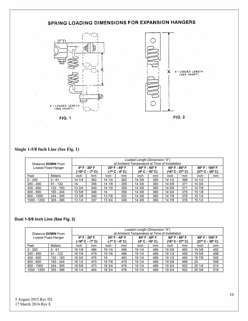
Ideally, the spring hangers supporting the vertical run of transmission line should be installed every 10 feet (3.1 m); however, minor variations may be used provided an average of one hanger for each 10 feet of line is maintained. The vertical portion of line near the top of the run should be anchored firmly using the appropriate fixed hanger(s). Spring-loading charts are used to set spring tensions of expansion hangers. See Fig. 1 & 2. After final installation, the line must be vertical and free to move in the hanger guides, and the hanger supports must keep the vertical hangers perpendicular to the line. The steel used to mount the top fixed hanger(s) must be sufficient to resist the large upward force on the vertical run. When installing transmission line, the preferred method is to start at the bottom and work toward the top. The transmission line must be mounted with the anchor insulator of each section at the top end.
The elbow which joins the vertical and horizontal runs should be a reinforced type.
HORIZONTAL RUN CONSIDERATIONS
In complex horizontal-line layouts involving elevation and direction changes, care must be exercised not to overstress mitre elbows or introduce excessive flexing of the line. Back to back elbows may be used to achieve desired vertical and horizontal angles.
As stated previously, the horizontal run should be at least as long as indicated in Table V, to allow for sufficient movement due to expansion of the vertical run. Adequate bending of the vertical line run to allow for movement of the horizontal run is assured by proper placement of the first vertical supporting ring as specified in Table IV. Three-point-suspension spring hangers should be used in the horizontal run for at least the
distance shown in Table V. Beyond the minimum distance specified, horizontal roller assemblies or swivel hangers may be used to support the line. Where several lines are in close proximity, special provision may be required to prevent lateral movement while allowing vertical movement. The line should be secured at the wall of the building using a horizontal anchor plate. Lines should be protected from falling ice.
INDOOR INSTALLATION CONSIDERATIONS The indoor part of the transmission line is normally not pressurized. Therefore, a gas stop is installed inside the building wall, and unpressurized line components are used between that point and the output of the transmitter. The arrangement permits disconnecting the ungassed portion of the line anywhere before the gas stop without loss of pressure in the outside line.
Indoor runs should be provided with a convenient arrangement of fittings on the output lines of the visual transmitter, aural transmitter and filterplexer to facilitate connection of a wattmeter and Dielectric dummy load.
PURGING MOISTURE FROM NEW LINE
A transmission line installation must be free of moisture before power is applied. Operating a line with moisture inside is likely to cause substantial damage. If moisture is suspected, the uppermost part of the line should be opened by using the petcock supplied or by slightly loosening the most-distant flange. The line should then be bled with dry (oil-pumped) nitrogen. Lines should be continuously pressurized from a nitrogen or a dry air source. After any complete loss of pressure where moisture may have entered, the line should be purged before it is again placed in use.
Should it be necessary to identify a leak, use non-ammonia based leak detection soap, such as Snoop, by Swagelok. If unavailable use a simple mixture of dish detergent and water. Ammonia and ammonia-based chemicals are extremely incompatible with brass and brass is one of the main components in transmission line and antenna systems. Ammonia makes the brass more susceptible to stress-corrosion cracking.
INSTALLATION PRECAUTIONS Care is required in handling the various transmission line components to prevent damage and assure proper installation. Procedures are outlined in “Transmission Line Do’s and Don’ts.” These recommendations are important.
Tower steel must be designed to support the vertical run in a straight line and maintain line clearance within spring hanger guide rings under load.

4 5 August 2015.Rev D2 17 March 2016.Rev E
TRANSMISSION LINE DO’s AND DON’Ts
DO
1. DO store packaged transmission line in clean dry place to
prevent contamination. 2. DO withdraw and inspect inner and outer conductors
completely if in previously opened or damaged shipping boxes.
3. DO withdraw and inspect all short pieces of line. 4. DO check operation of inner expander assembly* and any
components suspected of contamination with dirt or moisture.
5. DO cap all unpacked components against the entry of moisture.
6. DO hoist components with connector end up unless component is marked otherwise.
7. DO check the line in the spring hanger guides after each section is installed to ensure free movement for expansion. Shimming of guides at tower support may be necessary.
8. DO consult spring-loading dimensions (Fig. 1 or 2) for proper spring tension on expansion hangers and adjust each position on the tower accordingly.
9. DO ascertain that inner conductors of adjacent sections match alignment to prevent inadvertent damage to the connector. Hold top connector insulator in place and see that the insulator is well sealed before installing the next section.
10. DO tighten flange bolts alternately, one side, then the other, before final torquing. See Table VI.
11. DO use torque wrench for final tightening. See Table VI. 12. DO pressurize line immediately following installation and
maintain 3 lbs/in (0.21 kg/cm) at all times. Leaks must be repaired immediately.
13. DO keep ends of transmission line capped during installation. If installation is halted, seal installed line ends and pressurize to at least 0.5 lbs/in (0.04 kg/cm) with dry air or nitrogen.
14. DO coat O-ring gaskets lightly with Dow-Corning DC-4 silicone compound to ease assembly.
15. DO check O-ring and its groove for dirt or other foreign material and ascertain that ring is properly sealed before flange assembly.
*Check inner conductor expansion joint for an excursion of 0.2 inch (5mm) travel and in the extended position check for presence of contacting spring through exposed groove on inner conductor. In some lines the contacting spring is not visible in the extended position. Presence of the spring can be determined by inserting a 6-mil (0.15 mm) thick feeler gauge (0.5-inch or 13-mm wide) between the tubing inner surface and the connector body outer surface. If spring is present the feeler gauge can be inserted 0.25 inch (6.4 mm). If gauge goes in 0.5 inch (13 mm), spring is missing and the line section must not be used.
DON’T
1. DON’T withdraw complete inner conductor line section if
shipping box appears to be new and intact. ONLY inspect inner conductor expander.
2. DON’T hoist coupled sections of transmission line. The stresses involved damage components.
3. DON’T use force when fitting components together. If cause cannot be corrected or isn’t evident visually, call Dielectric for assistance.
4. DON’T assemble line components that contain water or condensation.
5. DON’T assemble line components that contain dust, dirt, packing material or other foreign objects. Contact Dielectric regarding any loose or suspicious material in the line as it is unpacked.
6. DON’T assemble match-marked components unless the marking is clear and understood. DON’T interchange match-marked items. Consult Dielectric about proper assembly.
7. DON’T install any line component with dust, dirt or grease on insulators.
8. DON’T install line that exhibits any evidence of damage. 9. DON’T attempt to correct defects unless instructed and
authorized by Dielectric. 10. DON’T dismiss rigger until transmission line is
completely installed and pressurized for at least 12 hours and the appropriate electrical tests are performed.
11. DON’T power the transmission line until the line is known to be dry and pressurized to at least 3 PSI.
12. DON’T over pressurize the line. Operating pressure of the transmission line should be between 3PSI and 6PSI
13. DON’T exceed specified torque for flange bolts (see Table VI).
14. DON’T use a line flange that shows evidence of being overstressed.
15. DON’T use a damaged o-ring. Use a new o-ring whenever in doubt.
16. DON’T bend elbow components to fit. If leg angle is incorrect, consult Dielectric.
17. DON’T let rigging equipment damage components. Provide proper protection.
18. DON’T cut tubing without cut-off gauge. If line is cut, remove all burrs and chips from inside and outside of tubing.
19. DON’T assemble a horizontal run without proper support.

5 5 August 2015.Rev D2 17 March 2016.Rev E
GENERAL COMPONENTS, DESCRIPTIONS, AND LOCATIONS
1. GAS STOP
Normally one gas stop is needed at each end of a coax run. Gas stops are used to stop dry air from entering into an area which does not require pressurization, or when different pressurizations are required.
2. GASSING KIT This supplies the connection of the tube and fittings from the dehydrator to the gas stop.
3. DEHYDRATOR Select the proper size dehydrator from Table III for the size and length of coax run.
4. SINGLE SWIVEL HANGERS These are used to provide a method to hang a single coax inside the transmitter room. These should be spaced approximately 10 ft. apart.
5. DUAL SWIVEL HANGERS These provide the user the ability to hang two runs of coax side by side inside the transmitter room. These should be spaced approximately 10 ft. apart.
6. RIGID FLANGED COAXIAL TRANSMISSION LINE This line is normally supplied in 19-1/2 ft., 19-3/4 ft., and 20 ft. lengths. They are bolted end to end with the connector always on the end towards the antenna or tower top. This allows observation of its condition and the coax contact prior to the installation of the next mating piece. Hardware is always supplied for one end of each component. See DO’S and DONT’S.
7. RIGID UNFLANGED COAXIAL TRANSMISSION LINE The unflanged coax is normally used inside the transmitter room where internal pressurization is not required.
8. HORIZONTAL ANCHOR PLATE These are normally used to anchor the coaxial transmission line to the building. They also permit the user to seal the building from the outside weather.
9. HORIZONTAL SPRING HANGERS (THREE POINT) These hangers are used to suspend the horizontal run and provide flexibility when warranted by expansion and contraction due to heating and cooling of the line. These are to be spaced 10 ft. apart.
10. HORIZONTAL ROLLERS This type of hanger is used only when the horizontal run far exceeds the length required to compensate for the vertical run. The hangers closest to the tower will require three-point suspension and rollers may be used beyond the required horizontal length (See Table IV).
11. LATERAL BRACES Used to restrict lateral motion of coax while permitting vertical and horizontal movement. One is normally attached at the bottom of the vertical run.
12. ELBOWS Two styles are usually available, “Equal leg” and “Unequal leg.” It is suggested that the unequal leg elbow be used in most places because it provides the maximum amount of support on the inner conductor. Equal leg elbows may be used to save space. Normally this is used at the bottom of the tower, in the elbow complex at the tower top and inside the building.
To provide extra strength of the outer conductor, we supply a reinforced type elbow for use on the tower. See DO’S and DON’TS & Torque specifications (Table VI).
13. VERTICAL SPRING HANGERS These hangers support the vertical run of coax and provide the flexibility required for vertical expansion and contraction due to temperature changes. See DO’S and DON’TS. Also see Spring Hanger Charts.
14. SOFT SOLDER FIELD FLANGES This provides the user with the ability to cut a section of coax to length and affix a flange using soldering equipment readily available in the field.
15. CUT OFF GUIDES Inner and outer cut off guides are required when doing an installation.
The purpose is to aid the user and produce an even, square cut when trimming a piece of coax to a required length.
16. END CAP These are used for a temporary closure of transmission line to prevent entrance of moisture and dust.
17. REDUCERS These are only provided where a reduction of coax size is needed. Two methods of reduction are available; one which reduces one size at a time and the other reduces two sizes at a time.
18. FIXED HANGERS These are used normally at the tower top to fix the vertical run in place.
6 5 August 2015.Rev D2 17 March 2016.Rev E
TRANSMISSION LINE INSTALLATION To assure proper flange alignment, pins have been placed in each flange and an alignment hole in the opposite side of the flange. The line is simply rotated until the pins align with the holes.
In order to provide pressurization, each piece of line is supplied with one o-ring seal. Care must be taken not to pinch or cut the seal during the installation. Also, a small amount of silicone grease may be applied to aid in sealing the joint. Only a shiny layer is sufficient; an overabundance may cause damage to the coax internally.
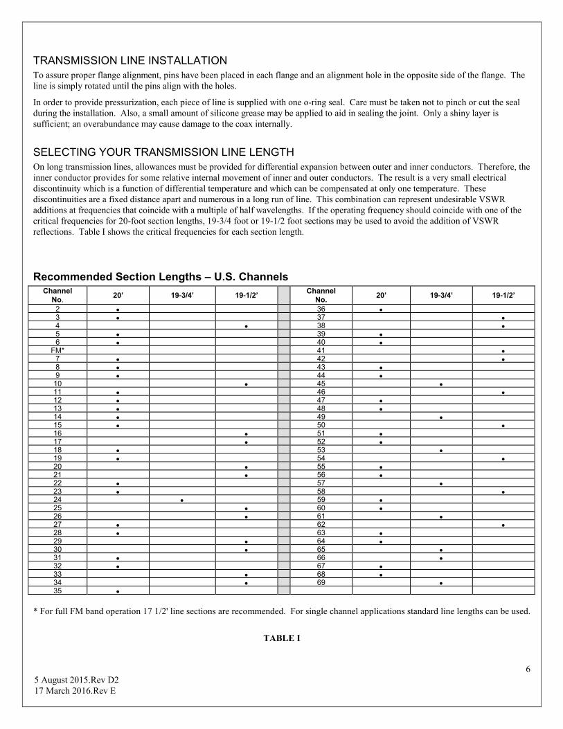
SELECTING YOUR TRANSMISSION LINE LENGTH On long transmission lines, allowances must be provided for differential expansion between outer and inner conductors. Therefore, the inner conductor provides for some relative internal movement of inner and outer conductors. The result is a very small electrical discontinuity which is a function of differential temperature and which can be compensated at only one temperature. These discontinuities are a fixed distance apart and numerous in a long run of line. This combination can represent undesirable VSWR additions at frequencies that coincide with a multiple of half wavelengths. If the operating frequency should coincide with one of the critical frequencies for 20-foot section lengths, 19-3/4 foot or 19-1/2 foot sections may be used to avoid the addition of VSWR reflections. Table I shows the critical frequencies for each section length.
Recommended Section Lengths – U.S. Channels Channel
No. 20’ 19-3/4’ 19-1/2’
Channel No.
20’ 19-3/4’ 19-1/2’
2 36 3 37 4 38 5 39 6 40
FM* 41 7 42 8 43 9 44
10 45 11 46 12 47 13 48 14 49 15 50 16 51 17 52 18 53 19 54 20 55 21 56 22 57 23 58 24 59 25 60 26 61 27 62 28 63 29 64 30 65 31 66 32 67 33 68 34 69 35
* For full FM band operation 17 1/2' line sections are recommended. For single channel applications standard line lengths can be used.
TABLE I

7 5 August 2015.Rev D2 17 March 2016.Rev E
VSWR Maximum Limit Values CHANNEL
RANGE LENGTH T/L RUN
3-1/8 DIA.
4-1/16 DIA.
6-1/8 DIA.
7-3/16 DIA.
8-3/16 9-3/16 DIA.
2-6 and FM 0 to 1000’ Regular 1.05 Regular 1.05 Regular 1.05 Regular 1.05 Regular 1.05 1000’ to 1500’ Regular 1.06 Regular 1.06 Regular 1.06 Regular 1.06 Regular 1.06 0 to 1000’ *Special 1.04 *Special 1.04 *Special 1.035 *Special 1.035 *Special 1.03 1000’ to 1500’ *Special 1.05 *Special 1.05 *Special 1.05 *Special 1.05 *Special 1.05
7-13 0 to 1000’ Regular 1.05 Regular 1.05 Regular 1.05 Regular 1.05 Regular 1.05 1000’ to 1500’ Regular 1.06 Regular 1.06 Regular 1.06 Regular 1.06 Regular 1.06 0 to 1000’ *Special 1.04 *Special 1.04 *Special 1.035 *Special 1.035 *Special 1.03 1000’ to 1500’ *Special 1.05 *Special 1.05 *Special 1.05 *Special 1.05 *Special 1.05
14-30 0 to 800’ Regular 1.05 Regular 1.05 Regular 1.05 Regular 1.05 Regular 1.05 800’ to 1500’ Regular 1.07 Regular 1.07 Regular 1.07 Regular 1.07 Regular 1.07 0 to 800’ *Special 1.035 *Special 1.035 *Special 1.03 *Special 1.035 *Special 1.03 800’ to 1500’ *Special 1.05 *Special 1.05 *Special 1.05 *Special 1.05 *Special 1.05
31-62 0 to 800’ Regular 1.06 Regular 1.06 Regular 1.05 Regular 1.05 ------------------- 800’ to 1500’ Regular 1.08 Regular 1.08 Regular 1.08 Regular 1.08 ------------------- 0 to 800’ *Special 1.05 *Special 1.05 *Special 1.04 *Special 1.04 ------------------- 800’ to 1500’ *Special 1.05 *Special 1.05 *Special 1.05 *Special 1.05 -------------------
31-52 0 to 800’ ------------------- ------------------- ------------------- ------------------- Regular 1.05 800’ to 1500’ ------------------- ------------------- ------------------- ------------------- Regular 1.08 0 to 800’ ------------------- ------------------- ------------------- ------------------- *Special 1.04 800’ to 1500’ ------------------- ------------------- ------------------- ------------------- *Special 1.05
*SPECIAL with application of our factory-installed tuners, DIELECTRIC has the capability of producing improved VSWRs. Contact factory for tuner applications and optimization details.
TABLE II
Recommended Maximum Transmission Line Lengths
for Dielectric Dehydrators
Model 1-5/8” 3-1/8” 4-1/16” 6-1/8” 7-3/16” 8-3/16” 9-3/16”
MX 200 5,800’ 1,500’ 875’ 375’ 280’ 214’ 169’ 600 XXX 3,000’ 1,700’ 750’ 555’ 425’ 325’
19-507-1200 XXX 6,000’ 3,550’ 1,525’ 1,110’ 850’ 675’ 19-507-2400 XXX XXX 6,808’ 2,974’ 2,155’ 1,650’ 1,300’ 19-507-3600 XXX XXX XXX 4,475’ 3,265’ 2,500’ 1,975’
XXX = Greater than 10,000 ft. IM 1600 Capabilities same as 19-507-2400 IM 2400 Capabilities same as 19-507-3600
All lengths are in feet
TABLE III
8 5 August 2015.Rev D2 17 March 2016.Rev E
TABLE IV
TABLE V

9 5 August 2015.Rev D2 17 March 2016.Rev E
Hardware Torque Specifications
TABLE VI
Hanger Clamp Torque Specifications
TABLE VII
10 5 August 2015.Rev D2 17 March 2016.Rev E
Single 1-5/8 Inch Line (See Fig. 1)
Distance DOWN From Lowest Fixed Hanger
Loaded Length (Dimension “X”) at Ambient Temperature at Time of Installation
0º F - 20º F (-18º C - -7º C)
20º F - 40º F (-7º C - 4º C)
40º F - 60º F (4º C - 16º C)
60º F - 80º F (16º C - 27º C)
80º F - 100º F (27º C - 38º C)
Feet Meters inch mm inch mm inch mm inch mm inch mm 0 - 200 0 - 61 14 1/4 362 14 1/4 362 14 3/8 365 14 1/2 368 14 1/2 200 - 400 61 - 122 14 356 14 1/8 359 14 3/8 365 14 5/8 371 14 3/4 400 - 600 122 - 183 13 3/4 349 14 1/8 359 14 3/8 365 14 5/8 371 14 7/8 600 - 800 183 - 244 13 5/8 346 14 356 14 3/8 365 14 3/4 375 15 1/8 800 - 1000 244 - 305 13 3/8 340 13 7/8 352 14 3/8 365 14 7/8 378 15 1/4 1000 - 1200 305 - 366 13 1/4 337 13 3/4 349 14 3/8 365 14 7/8 378 15 1/2
Dual 1-5/8 Inch Line (See Fig. 2)
Distance DOWN From Lowest Fixed Hanger
Loaded Length (Dimension “X”) at Ambient Temperature at Time of Installation
0º F - 20º F (-18º C - -7º C)
20º F - 40º F (-7º C - 4º C)
40º F - 60º F (4º C - 16º C)
60º F - 80º F (16º C - 27º C)
80º F - 100º F (27º C - 38º C)
Feet Meters inch mm inch mm inch mm inch mm inch mm 0 - 200 0 - 61 19 1/8 486 19 1/4 489 19 1/4 489 19 3/8 492 19 3/8 492 200 - 400 61 - 122 18 7/8 479 19 1/8 486 19 1/4 489 19 1/2 495 19 5/8 498 400 - 600 122 - 183 18 3/4 476 19 483 19 1/4 489 19 1/2 495 19 7/8 505 600 - 800 183 - 244 18 1/2 470 18 7/8 479 19 1/4 489 19 5/8 498 20 508 800 - 1000 244 - 305 18 5/8 473 18 3/4 476 19 1/4 489 19 3/4 502 20 1/4 514 1000 - 1200 305 - 366 18 1/4 464 18 3/4 476 19 1/4 489 19 3/4 502 20 3/8 518

11 5 August 2015.Rev D2 17 March 2016.Rev E
Single 3 1/8-Inch Line (See Fig. 1)
Distance DOWN From Lowest Fixed Hanger
Loaded Length (Dimension “X”) at Ambient Temperature at Time of Installation
0º F - 20º F (-18º C - -7º C)
20º F - 40º F (-7º C - 4º C)
40º F - 60º F (4º C - 16º C)
60º F - 80º F (16º C - 27º C)
80º F - 100º F (27º C - 38º C)
Feet Meters inch mm inch mm inch mm inch mm inch mm 0 - 200 0 - 61 16 1/4 413 16 3/8 416 16 3/8 416 16 1/2 419 16 5/8 422 200 - 400 61 - 122 16 406 16 1/4 413 16 3/8 416 16 5/8 422 16 7/8 429 400 - 600 122 - 183 15 3/4 400 16 406 16 3/8 416 16 3/4 425 17 1/8 435 600 - 800 183 - 244 15 1/2 394 15 7/8 403 16 3/8 416 16 7/8 429 17 3/8 441 800 - 1000 244 - 305 15 1/4 387 15 3/4 400 16 3/8 416 17 432 17 5/8 448 1000 - 1200 305 - 366 15 381 15 3/4 400 16 3/8 416 17 1/8 435 17 3/4 451 1200 - 1400 366 - 427 14 7/8 378 15 5/8 397 16 3/8 416 17 1/8 435 17 7/8 454 1400 - 1600 427 - 488 14 3/4 375 15 5/8 397 16 3/8 416 17 1/4 438 18 457 1600 - 1800 488 - 549 14 5/8 371 15 1/2 394 16 3/8 416 17 1/4 438 18 1/8 460 1800 - 2000 549 - 610 14 1/2 368 15 1/2 394 16 3/8 416 17 3/8 441 18 1/4 464
Dual 3 1/8-Inch Line (See Fig. 2)
Distance DOWN From Lowest Fixed Hanger
Loaded Length (Dimension “X”) at Ambient Temperature at Time of Installation
0º F - 20º F (-18º C - -7º C)
20º F - 40º F (-7º C - 4º C)
40º F - 60º F (4º C - 16º C)
60º F - 80º F (16º C - 27º C)
80º F - 100º F (27º C - 38º C)
Feet Meters inch mm inch mm inch mm inch mm inch mm 0 - 200 0 - 61 24 1/4 616 24 5/8 625 24 3/4 629 24 3/4 629 24 7/8 632 200 - 400 61 - 122 24 1/4 616 24 1/2 622 24 3/4 629 24 7/8 632 25 1/8 638 400 - 600 122 - 183 24 610 24 3/8 619 24 3/4 629 25 635 25 3/8 645 600 - 800 183 - 244 23 3/4 603 24 1/4 616 24 3/4 629 25 1/8 638 25 5/8 651 800 - 1000 244 - 305 23 1/2 597 24 1/8 613 24 3/4 629 25 1/4 641 25 7/8 657 1000 - 1200 305 - 366 23 3/8 594 24 610 24 3/4 629 25 3/8 645 26 1/8 664 1200 - 1400 366 - 427 23 1/8 587 23 7/8 606 24 3/4 629 25 1/2 648 26 1/4 667 1400 - 1600 427 - 488 23 584 23 7/8 606 24 3/4 629 25 1/2 648 26 3/8 670 1600 - 1800 488 - 549 22 7/8 581 23 3/4 603 24 3/4 629 25 5/8 651 26 1/2 673 1800 - 2000 549 - 610 22 3/4 578 23 3/4 603 24 3/4 629 25 5/8 651 26 5/8 676
Single 4 1/16-Inch Line (See Fig. 1)
Distance DOWN From Lowest Fixed Hanger
Loaded Length (Dimension “X”) at Ambient Temperature at Time of Installation
0º F - 20º F (-18º C - -7º C)
20º F - 40º F (-7º C - 4º C)
40º F - 60º F (4º C - 16º C)
60º F - 80º F (16º C - 27º C)
80º F - 100º F (27º C - 38º C)
Feet Meters inch mm inch mm inch mm inch mm inch mm 0 - 200 0 - 61 17 7/8 454 18 457 18 1/8 460 18 1/8 460 18 1/4 464 200 - 400 61 - 122 17 5/8 448 17 7/8 454 18 1/8 460 18 1/4 464 18 1/2 470 400 - 600 122 - 183 17 3/8 441 17 3/4 451 18 1/8 460 18 3/8 467 18 3/4 476 600 - 800 183 - 244 17 1/4 438 17 5/8 448 18 1/8 460 18 1/2 470 19 483 800 - 1000 244 - 305 17 432 17 1/2 445 18 1/8 460 18 5/8 473 19 1/8 486 1000 - 1200 305 - 366 16 3/4 425 17 1/2 445 18 1/8 460 18 3/4 476 19 3/8 492 1200 - 1400 366 - 427 16 5/8 422 17 3/8 441 18 1/8 460 18 3/4 476 19 1/2 495 1400 - 1600 427 - 488 16 1/2 419 17 1/4 438 18 1/8 460 18 7/8 479 19 5/8 498 1600 - 1800 488 - 549 16 3/8 416 17 1/4 438 18 1/8 460 18 7/8 479 19 3/4 502 1800 - 2000 549 - 610 16 1/4 413 17 1/8 435 18 1/8 460 19 483 19 7/8 505

12 5 August 2015.Rev D2 17 March 2016.Rev E
Single 6 1/8-Inch Line 75 Ohm (See Fig. 2)
Distance DOWN From Lowest Fixed Hanger
Loaded Length (Dimension “X”) at Ambient Temperature at Time of Installation
0º F - 20º F (-18º C - -7º C)
20º F - 40º F (-7º C - 4º C)
40º F - 60º F (4º C - 16º C)
60º F - 80º F (16º C - 27º C)
80º F - 100º F (27º C - 38º C)
Feet Meters inch mm inch mm inch mm inch mm inch mm 0 - 200 0 - 61 32 813 32 813 32 1/8 816 32 1/8 816 32 1/4 819 200 - 400 61 - 122 31 3/4 806 31 7/8 810 32 1/8 816 32 3/8 822 32 1/2 826 400 - 600 122 - 183 31 3/8 797 31 3/4 806 32 1/8 816 32 1/2 826 32 7/8 835 600 - 800 183 - 244 31 1/8 791 31 5/8 803 32 1/8 816 32 5/8 829 33 1/8 841 800 - 1000 244 - 305 30 7/8 784 31 1/2 800 32 1/8 816 32 3/4 832 33 3/8 848 1000 - 1200 305 - 366 30 5/8 778 31 3/8 797 32 1/8 816 32 7/8 835 33 5/8 854 1200 - 1400 366 - 427 30 1/2 775 31 1/4 794 32 1/8 816 33 838 33 3/4 857 1400 - 1600 427 - 488 30 1/4 768 31 1/8 791 32 1/8 816 33 838 34 864 1600 - 1800 488 - 549 30 762 31 1/8 791 32 1/8 816 33 1/8 841 34 1/8 867 1800 - 2000 549 - 610 29 7/8 759 31 787 32 1/8 816 33 1/4 845 34 1/4 870
Single 6 1/8-Inch Line 50 Ohm (See Fig. 2)
Distance DOWN From Lowest Fixed Hanger
Loaded Length (Dimension “X”) at Ambient Temperature at Time of Installation
0º F - 20º F (-18º C - -7º C)
20º F - 40º F (-7º C - 4º C)
40º F - 60º F (4º C - 16º C)
60º F - 80º F (16º C - 27º C)
80º F - 100º F (27º C - 38º C)
Feet Meters inch mm inch mm inch mm inch mm inch mm 0 - 200 0 - 61 34 1/8 867 34 1/4 870 34 3/8 873 34 3/8 873 34 1/2 876 200 - 400 61 - 122 33 7/8 860 34 1/8 867 34 3/8 873 34 1/2 876 34 3/4 883 400 - 600 122 - 183 33 5/8 854 34 864 34 3/8 873 34 5/8 879 35 889 600 - 800 183 - 244 33 3/8 848 33 7/8 860 34 3/8 873 34 3/4 883 35 1/4 895 800 - 1000 244 - 305 33 1/8 841 33 3/4 857 34 3/8 873 34 7/8 886 35 1/2 902 1000 - 1200 305 - 366 32 7/8 835 33 5/8 854 34 3/8 873 35 889 35 3/4 908 1200 - 1400 366 - 427 32 5/8 829 33 1/2 851 34 3/8 873 35 1/8 892 36 914 1400 - 1600 427 - 488 32 1/2 826 33 3/8 848 34 3/8 873 35 1/4 895 36 1/8 918 1600 - 1800 488 - 549 32 1/4 819 33 1/4 845 34 3/8 873 35 3/8 899 36 3/8 924 1800 - 2000 549 - 610 32 1/8 816 33 1/4 845 34 3/8 873 35 1/2 902 36 1/2 927
Single 7 3/16-Inch 75 Ohm Vertical Spring Hanger (See Fig. 2)
Distance DOWN From Lowest Fixed Hanger
Loaded Length (Dimension “X”) at Ambient Temperature at Time of Installation
0º F - 20º F (-18º C - -7º C)
20º F - 40º F (-7º C - 4º C)
40º F - 60º F (4º C - 16º C)
60º F - 80º F (16º C - 27º C)
80º F - 100º F (27º C - 38º C)
Feet Meters inch mm inch mm inch mm inch mm inch mm 0 - 200 0 - 61 33 5/8 854 33 3/4 857 33 7/8 860 33 7/8 860 34 864 200 - 400 61 - 122 33 3/8 848 33 5/8 854 33 7/8 860 34 864 34 1/4 870 400 - 600 122 - 183 33 1/8 841 33 1/2 851 33 7/8 860 34 1/4 870 34 1/2 876 600 - 800 183 - 244 32 7/8 835 33 3/8 848 33 7/8 860 34 3/8 873 34 7/8 886 800 - 1000 244 - 305 32 5/8 829 33 1/4 845 33 7/8 860 34 1/2 876 35 1/8 892 1000 - 1200 305 - 366 32 3/8 822 33 1/8 841 33 7/8 860 34 5/8 879 35 3/8 899 1200 - 1400 366 - 427 32 1/8 816 33 838 33 7/8 860 34 3/4 883 35 5/8 905 1400 - 1600 427 - 488 32 813 33 838 33 7/8 860 34 3/4 883 35 3/4 908 1600 - 1800 488 - 549 31 7/8 810 32 7/8 835 33 7/8 860 34 7/8 886 35 7/8 911 1800 - 2000 549 - 610 31 3/4 806 32 3/4 832 33 7/8 860 35 889 36 914

13 5 August 2015.Rev D2 17 March 2016.Rev E
Single 8 3/16-Inch Line (See Fig. 2)
Distance DOWN From Lowest Fixed Hanger
Loaded Length (Dimension “X”) at Ambient Temperature at Time of Installation
0º F - 20º F (-18º C - -7º C)
20º F - 40º F (-7º C - 4º C)
40º F - 60º F (4º C - 16º C)
60º F - 80º F (16º C - 27º C)
80º F - 100º F (27º C - 38º C)
Feet Meters inch mm inch mm inch mm inch mm inch mm 0 - 200 0 - 61 27 3/4 704 27 7/8 706 28 711 28 711 28 1/8 714 200 - 400 61 - 122 27 1/2 699 27 3/4 704 28 711 28 1/4 717 28 3/8 720 400 - 600 122 - 183 27 1/4 692 27 5/8 702 28 711 28 3/8 720 28 3/4 730 600 - 800 183 - 244 27 686 27 1/2 699 28 711 28 1/2 724 29 737 800 - 1000 244 - 305 26 3/4 679 27 3/8 693 28 711 28 5/8 733 29 1/4 743 1000 - 1200 305 - 366 26 1/2 673 27 1/4 692 28 711 28 3/4 730 29 1/2 749 1200 - 1400 366 - 427 26 1/4 666 27 1/8 689 28 711 28 7/8 733 29 5/8 755 1400 - 1600 427 - 488 26 1/8 664 27 686 28 711 28 7/8 733 29 7/8 759 1600 - 1800 488 - 549 25 7/8 655 27 686 28 711 29 737 30 762 1800 - 2000 549 - 610 25 3/4 654 26 7/8 683 28 711 29 1/8 740 30 1/8 765
Single 9 3/16-Inch Line (See Fig. 2)
Distance DOWN From Lowest Fixed Hanger
Loaded Length (Dimension “X”) at Ambient Temperature at Time of Installation
0º F - 20º F (-18º C - -7º C)
20º F - 40º F (-7º C - 4º C)
40º F - 60º F (4º C - 16º C)
60º F - 80º F (16º C - 27º C)
80º F - 100º F (27º C - 38º C)
Feet Meters inch mm inch mm inch mm inch mm inch mm 0 - 200 0 - 61 31 1/8 791 31 1/8 791 31 1/4 794 31 1/4 794 31 3/8 797 200 - 400 61 - 122 30 3/4 781 31 787 31 1/4 794 31 1/2 800 31 5/8 803 400 - 600 122 - 183 30 1/2 775 30 7/8 784 31 1/4 794 31 5/8 803 31 7/8 809 600 - 800 183 - 244 30 1/4 768 30 3/4 781 31 1/4 794 31 3/4 806 32 1/8 815 800 - 1000 244 - 305 30 762 30 5/8 778 31 1/4 794 31 7/8 809 31 1/2 826 1000 - 1200 305 - 366 29 3/4 756 30 1/2 775 31 1/4 794 32 812 32 3/8 822 1200 - 1400 366 - 427 29 1/2 749 30 5/8 779 31 1/4 794 32 1/8 815 32 7/8 835 1400 - 1600 427 - 488 29 1/4 743 30 1/4 768 31 1/4 794 32 1/8 815 33 1/8 841 1600 - 1800 488 - 549 29 1/8 740 30 1/8 765 31 1/4 794 32 1/4 819 33 7/8 841 1800 - 2000 549 - 610 28 7/8 733 30 762 31 1/4 794 32 3/8 822 33 1/2 850

14 5 August 2015.Rev D2 17 March 2016.Rev E
Single Horizontal Three-Point Suspension Hangers Free Length-No Load

15 5 August 2015.Rev D2 17 March 2016.Rev E
Note: This product may be covered by one or more of the following patents: 6,816,040; 6,650,209; 4,654,962; 5,455,548 or 5,401,173.
Additional patents may be pending.
Special Instructions
for digiTLine Installations
excluding Ultimate Connectors In order to achieve the extreme broadband performance that Dielectric's digiTLine is capable of, each connector must be properly seated during installation. In order to accomplish this, the installation should begin at the transmitter end of the horizontal run with line section number 1. After each transmission line section is bolted on, the inner conductor must be seated on the anchor connector of the previous section. This is done by inserting the connector seating tool (essentially a 10" long, 3/4" diameter rod) into the exposed connector until it bottoms out on the first magneformed bushing. Then by pushing or gently tapping with a rubber mallet, the inner conductor is seated onto the previous anchor connector. The total amount of inner conductor travel should be about .25". This process is repeated for every flange joint in the horizontal and vertical run.
****NOTE**** Failure to follow these instructions will result in degraded VSWR performance.
If you have any questions, please call Dielectric at 1-207-655-8100

16 5 August 2015.Rev D2 17 March 2016.Rev E