rigid-plastic analysis of seismic resistant t-frame
TRANSCRIPT
Research ArticleRigid-Plastic Analysis of Seismic Resistant T-Frame consideringMoment-Shear Interaction
Ghader Bagheri 1 Payam Ashtari 2 and Farhad Behnamfar 3
1Department of Civil Engineering Isfahan (Khorasgan) Branch Islamic Azad University Isfahan Iran2Department of Civil Engineering University of Zanjan Zanjan Iran3Department of Civil Engineering Isfahan University of Technology Isfahan Iran
Correspondence should be addressed to Ghader Bagheri ghbagheriiauzacir
Received 17 September 2020 Revised 6 June 2021 Accepted 20 June 2021 Published 6 July 2021
Academic Editor Paola Forte
Copyright copy 2021 Ghader Bagheri et al )is is an open access article distributed under the Creative Commons Attribution Licensewhich permits unrestricted use distribution and reproduction in any medium provided the original work is properly cited
To select a seismic resistant system in addition to strength and stiffness ductility and energy dissipation are important to beconsidered Structures have nonlinear behavior under the influence of moderate and strong earthquakes One of the primary aimsin designing seismic resistant structures is to prevent the formation of undesirable collapse mechanisms such as the collapse inonly a few storeys of the structure that leads to low energy dissipation In order to achieve a global collapse mechanism modernseismic codes provide simple rules for design which is called the hierarchy criteria Although these simple criteria could preventthe formation of a soft storey mechanism they could not lead to an optimal global collapse mechanism In these mechanisms theenergy dissipation zones include all the yielding zones such as beams while all other parts of the structure have remained in theelastic range TRF (T-resisting frame) is an innovative lateral resistant system introduced for architectural reasons and to providemore energy dissipating capability )is system has several collapse mechanisms due to the moment shear or moment-shearbehavior of its members In this paper within the framework of the theory of plastic mechanism control the rigid-plastic analysisof the TRF system to achieve the desired collapse mechanism is used by considering the moment-shear interaction According tothese analyses which are performed on a single storey frame simple hierarchy criteria are developed to create the desired collapsemechanism Also these criteria prevent undesired collapse mechanisms in order to have more energy dissipation and moreductility Finally the validity of the proposed criteria has been verified by the pushover analysis
1 Introduction
T-resisting frame is a new lateral force resisting system whichconsists of two structural parts T-part as themain componentand the second part of side columns In steel structures T-partis composed of a vertical plate girder (VPG) and a pair ofhorizontal plate girders (HPGs) to provide significant lateralstiffness and high energy dissipation capability under severeearthquakes TRF dissipates energy predominantly throughstable shear yielding of the web shear panels of HPGs Alsoside columns in TRF such as columns in conventional bracedframes withstand compression or tension to resist theoverturning moments (Figure 1) [1]
Ashtari proposed the configuration of TRF in 2008 andBandehzadeh in the MSc thesis demonstrated the seismicperformance advantages of the optimized single-T TRFs [1]
Ashtari (2008) to provide and improve buildingrsquos behavior andperformance presented the initial idea of this lateral seismicsystem Initial numerical and experimental studies have beenconducted on the behavior and performance of the TRF systemby Ashtari et al [1 2ndash5])e results of nonlinear finite elementanalyses in this system demonstrate that TRF has high initialstiffness high ductility excellent energy dissipation capacityand stable hysteretic behavior at large inelastic deformationsunder numerous cycles of loading According to the resultsfrom a series of nonlinear analyses a properly designed TRFexhibited a great efficiency as the lateral resistant system of abuilding in a high seismic zone due to its potential for ex-tremely high ductility and energy dissipating capability In thisbuilding the observed drifts and rotation demands were sig-nificantly lower than those commonly associated with thebuildings using commonmoment-resisting frames [1] Various
HindawiShock and VibrationVolume 2021 Article ID 8844039 12 pageshttpsdoiorg10115520218844039
numerical studies and laboratory tests have been performed ondifferent configurations of this system )e results show thatthis system has good seismic behavior )e results show thatthis system has high initial stiffness high ductility excellentenergy dissipation capacity and stable hysteretic behavior atlarge inelastic deformations under numerous cycles of loading[4 5]
In the capacity design the energy dissipation zonesshould be designed according to the internal forces resultingfrom the load combinations provided by the seismic codes)e other parts of the structure have to be designed pro-portionally to the force of the energy dissipation zones Itmeans that these parts do not yield under the maximuminternal reactions transmitted by the energy dissipationzones in the fully yielded state [6 7]
In the eccentrically braced frames dissipative zones areconstituted by the members called link elements [8ndash10] )euse of members as energy dissipation zones which they areyielding in shear was originally proposed for eccentricallybraced frames )is issue has been the starting point for theformation of new structural types such as knee braces [11]aluminum shear links [12] and shear links made of low-flowpoint steel [13] Shear yielding is separated from the energydissipation due to moment yielding so the moment-shearinteraction could not be neglected
In this paper the TRF-H system has been studied inwhich the task of energy dissipation is assigned to the T-partmembers as link elements which are affected by momentshear or moment-shear interaction )e problem of mo-ment-shear interaction is considered within the frameworkof rigid-plastic analysis and the solution for the TRF-Hsystem is presented Solving the interaction problem is af-fected by compatibility conditions which depend on theconfiguration of the structure Such issue is currently beingstudied for eccentrically braced frames with D-schemeK-scheme V-scheme inverted V-scheme [14] and Y EB-
Frames [15] and here for the T-resisting frame system )epurpose of developing the hierarchy criteria is to control theyielding pattern Investigations are focused on the one-storey TRF-H system to determine which members and howthey yield )is theory is based on the rigid-plastic analysiswith the purpose of achieving the global collapse mecha-nism in which all the dissipation zones are yielding whilethe other members stay in the elastic range )is theory hasbeen presented for frames with horizontal link beam [16]knee braces (KB-frame) [17] dual MRF-CBF systems [18]and truss moment frame (DTMFs) [19] Also the solution ofthe theory of plastic mechanism control (TPMC) currentlybeing studied in the case of moment-resisting frames ec-centrically braced frames (MRF-EBF) dual systems [20] andeccentrically braced frames with inverted Y-scheme [21])ese studies provide a complete and exhaustive designprocedure for MRF-EBF dual systems and EB-frames withinverted Y-scheme considering all the brace configurationscommonly adopted and with the goal of assuring the de-velopment of a collapse mechanism of global type [20 21]
In Section 2 the study of moment-shear interaction inthe TRF-H system and the development of the hierarchycriteria at the storey level have been studied To assess theaccuracy of the proposed hierarchy criteria for the TRF-Hsystem has been examined by means of static pushoveranalyses with the SAP2000 computer program In additionthe theory of controlling plastic mechanisms for the mul-tistorey TRF system and fixedmultistorey TRF systemwouldbe provided in subsequent papers
2 The PlasticMechanisms in the TRF-H System
Independent from the configuration of the structure themain feature of the links is due to the interaction between thebending moment and the shear force which could not beignored in predicting the ultimate behavior of the structural
HPG HPG
Com
posit
es
colu
mn
VPG
HPG HPG
RC si
deco
lum
n
RC w
all
HPG HPG
Side
colu
mn
Vtr
uss
HPG HPG
Side
colu
mn
Side
colu
mn
VPG
HPG HPG
Side
colu
mn
VPG
HPG HPGSi
deco
lum
n
VPG
Side
colu
mn
Side
colu
mn
Side
colu
mn
VPG
VPG
HPG HPG HPG
Side
colu
mn
HPG HPG HPG
Side
colu
mn
VPG
VPG
VPG
(a)
(d) (e) (f) (g) (h)
(b) (c)
Figure 1 Proposed basic structural configurations of TRF and alternatives [1] (a) Single-T configuration of TRF (b) Double-T con-figuration of TRF (c) Multi-T configuration of TRF (d) Stylish single-T configuration of TRF (e) Stylish single-T configuration of TRF(f ) Single-T configuration of TRF using vertical truss (g) Single-T configuration of TRF using composite side columns (h) Single-Tconfiguration of reinforced concrete TRF
2 Shock and Vibration
system Generally the classification of the link beams de-pends on the length of the member In the following generalclassification is proposed [7ndash10]
(i) Short link for ele 16MPVP
(ii) Intermediate link for 16MPVP le ele 3MPVP
(iii) Long links for ege 3MPVP
Vp and Mp respectively are plastic shear strength andbending strength of the cross section of the link beam )elong link beam is considered to be in frequent revisions as26MPVP [22ndash24] Moment-shear interaction diagram andthe short medium and long linksrsquo range are shown inFigure 2
)e plastic behavior of the link beam for a bendingmoment less than Mf could be considered as a pure shearwhere Mf is the flange contribution of the plastic moment ofthe link beam thus for moments greater than Mf the shearstrength of the element is reduced due to the interactionbetween moment and shear According to Neal research theplastic zone is calculated using the following relationships[14 25]
|M| minus Mf
Mp minus Mf
1113888 1113889
2
+V
Vp
1113888 1113889
2
1 forMf le |M|leMP (1)
V Vp for|M|leMf (2)
In capacity design an important issue that has beenreported in previous experiments by Hjelmstad and Popov[26] and Malley and Popov [27] is the overstrength de-veloped by the link beam Overstrength of the link beam isthe ratio between the maximum shear forces developed bythe link beam to its plastic shear strength )e evaluation ofthe results of experiments is usually based on the inclusionof the plastic shear strength as VP 06fy(d minus tf)tw wherefy is the yield stress d is the depth of the cross section ofthe beam and tf and tw are the thickness of the flange andthe web respectively However the link overstrength oc-curs due to the strain hardening and the contribution oflink flanges to the shear strength )erefore according toEuropean codes [28] plastic shear strength is calculatedusing the web surface shear strength with the contributionof the flange
According to the capacity design the link overstrengthshould be calculated in the assessment of the maximuminternal forces transferred to the nonplastic elements )elink overstrength factor is generally recommended as 150based on previous experimental studies [29] In the 2005AISC seismic provisions [23] the link overstrength factor isproposed equal to 125 for designing the diagonal bracesand equal to 110 for designing columns and the beamoutside the link A similar approach has been adopted inthe eurocode [6] Recent experimental results and inves-tigations are indicated that overstrength factors can beexceeding the code suggested values For very short linkswith compact cross-sections and perfect axial restraintsvalues of shear overstrength up to 2 have been obtainedFor built-up links with a very compact shape and short
length even larger values could be obtained especially iflarger rotation capacity is achievable [30] Barecchia et alby means of finite element analyses on standard Europeanrolled profiles have found overstrength factors between200 and 250 for a link shear deformation equal to 010 rad[31] Nevertheless in using the above results some cautionshould be adopted because they come from finite elementanalyses where the stiffenersrsquo influence cannot be calculatedaccurately
Recently Okazaki et al based on several experimentaltests on shear links with properly detailed web stiffenerhave obtained the overstrength factor between 134 and148 for short links and in the range of 112ndash128 for longerlinks [24] )ese experimental results of the overstrengthfactor have been computed considering the measuredvalues of the material properties )erefore based on theseexperimental results it was concluded that the overstrengthfactor of 150 which forms worldwide the basis of capacitydesign provisions for EB-frames and appears reasonable forlinks made from rolled profiles A simple method forcalculating the overstrength of the hierarchy criteria ob-tained by the rigid-plastic analysis has recently been pre-sented [14] It is based on the use of the interaction domainreferring to the ultimate conditions obtained from thehomothetic or nonhomothetic expansion of the plasticdomain (Figure 2)
)e topologies of the plastic collapse mechanisms of theone-storey TRF-H are shown in Figure 3 In the type ldquoArdquomechanism ends of the both horizontal links and thebottom of the central column yield In mechanism ldquoBrdquo twoends of the central column yield Type of collapse mecha-nism is determined by the elements and structure specifi-cation)e aim of the research presented here is to define thehierarchy criteria which includes the effect of the moment-shear interaction to ensure that the desired mechanismwould be developed
In fact in order to calculate the moment and shearinteraction in the framework of rigid-plastic analysis theend-link yield is modeled with a combination of a pair ofplastic double pendulum and a plastic hinge that can
0
1
0 1
Short link
Long link
Intermediatelink
p
Plastic domain
Nonhomotheticexpanded domain
MMp
Ωmmiddotp Ωm
VV p
Ωv
sv
Ωvmiddotsv
(Ωm = Ωv)
Ultimate domain
Homotheticexpandeddomain
Figure 2 Moment-shear interaction diagram (p MfMp)
Shock and Vibration 3
calculate both types of plastic shear deformation ]P andmoment plastic rotation ϕp respectively
Use of the rigid-plastic analysis to calculate the plasticstrength of possible mechanisms needs to determine theplastic deformations of the links ]P and ϕp Also the valuesof shear force V and corresponding moment M for a givenvalue of the θ parameter is needed Problem solving could bedone by minimizing the internal work of the link and ap-plying the yielding conditions and considering of the normalplastic flow rule Additionally compatibility conditionsshould be satisfied
3 Moment-Shear Interaction in TRF-HSystem Elements
In the equations the index of parameters is based on thememberrsquos names meaning the BL and BR indexes are related
to the left and right horizontal link (beam) respectively andthe AB is related to the vertical member (central column)
31 Mechanism Type ldquoArdquo Within the framework of rigid-plastic analysis moment-shear interaction occurring in thelink of EB-frames is provided in the prior studies [15] )emoment and shear interaction in the elements of the TRF-Hframe (Figure 3(a)) within the framework of the rigid-plastic analysis is obtained by the following relationships(equations (3)ndash(10))
(1) Minimizing the internal work Wi according to thecollapse mechanism under the influence of theplastic rotation θ at the columns for a hinge state is
Min W(A)i M
(A)BL ϕ(A)
pBL + ϕ(A)pAB1113872 1113873 + V
(A)BL v
(A)pBL + M
(A)BR ϕ(A)
pBR + ϕ(A)pAB1113872 1113873 + V
(A)BR v
(A)pBR + M
(A)AB ϕ
(A)pAB + V
(A)AB v
(A)pAB (3)
(2) Kinematic compatibility conditions are
v(A)pBL + ϕ(A)
pBLeL 0 (4)
v(A)pBR + ϕ(A)
pBReR 0 (5)
v(A)pAB + ϕ(A)
pABh θh (6)
(3) Elementsrsquo yield condition leads to these threefunctions
F M(A)BL V
(A)BL1113872 1113873
M(A)BL
11138681113868111386811138681113868
11138681113868111386811138681113868 minus Mfb
Mpb minus Mfb
⎛⎝ ⎞⎠
2
+V
(A)BL
Vpb
1113888 1113889
2
minus 1
(7)
F M(A)BR V
(A)BR1113872 1113873
M(A)BR
11138681113868111386811138681113868
11138681113868111386811138681113868 minus Mfb
Mpb minus Mfb
⎛⎝ ⎞⎠
2
+V
(A)BR
Vpb
1113888 1113889
2
minus 1
(8)
F M(A)AB V
(A)AB1113872 1113873
M(A)AB
11138681113868111386811138681113868
11138681113868111386811138681113868 minus Mfc
Mpc minus Mfc
⎛⎝ ⎞⎠
2
+V
(A)AB
Vpc
1113888 1113889
2
minus 1
(9)
(4) Normal plastic flow law gives
v(A)p λ
zF
zV(A)
ϕ(A)p λ
zF
zM(A)
(10)
HereM(A)and V(A) are themoment and the shear formedat the end of TRF-H elements respectively ϕ(A)
P and ](A)P are
the plastic rotation and plastic shear deformation occurring inthe mechanism ldquoArdquo respectively e is length of the link h isheight of the storey and θ is the plastic rotation at the end of thebeam and columns )e ldquobrdquo and ldquocrdquo index are for the TRF-Hhorizontal link beam and central column respectively For each
Δ
θ
pBL
pBR
pAB
vpBL
vpAB
vpBR
(a)
θ
Δ
pAB
vpAB
vpAB
(b)
Figure 3 Modeling TRF-H system by considering the moment and shear interaction (a) Mechanism ldquoArdquo (b) Mechanism ldquoBrdquo
4 Shock and Vibration
member of the TRF-H system the values of the shear and themoment would be determined using the above equations)ese calculations aremade for the left horizontal link (BL) theright horizontal link (BR) and the central column of the TRF-H (AB) system For the BL member by substituting equations(4)ndash(6) into equation (3) an equation will be obtained thatexpresses the internal work as a function of the plastic rotationof the T-partrsquos members (ϕp) So minimizing the internal workof each member could be expressed as
dW(A)i
dϕ(A)pBL
0⟶ V(A)BL
M(A)BL
eL
(11)
dW(A)i
dϕ(A)pBR
0⟶ V(A)BR
M(A)BR
eR
(12)
dW(A)i
dϕ(A)pAB
0⟶ V(A)AB
M(A)BL + M
(A)BR + M
(A)AB
h (13)
By defining the plastic moment of the web as Mw
(Mw Mp + Mf) and by combining equations (7)ndash(9) withequations (11)ndash(13) for all T-part members the value ofM(A) and V(A) could be determined
)e value of M(A) and V(A) for the left horizontal link(BL) is determined as follows
M(A)BL
Mfb + Mwb
1 minus M2fb minus M
2wb1113872 1113873V2
pbe2L1113872 1113873
1113969
1 + M2wbV
2pbe
2L1113872 1113873
(14)
V(A)BL
Mfb + Mwb
1 minus M2fb minus M
2wb1113872 1113873V2
pbe2L1113872 1113873
1113969
eL 1 + M2wbV
2pbe
2L1113872 11138731113872 1113873
(15)
By defining the parameter pb MfbMpb the momentscan be rewritten based on the beamrsquos plastic momentAccordingly by substituting the values of in Mfb pbMpb
and Mwb (1 minus pb)Mpb and Vpb (4(1 minus pb)3
radichwb)
Mpb into equation (14) the BL moment is defined as thebeam plastic moment coefficient as follows
M(A)BL x
(A)BL middot Mpb (16)
V(A)BL
x(A)BL
eL
middot Mpb (17)
In these equations the multiplier x(A)BL is equal to
x(A)BL
pb + 1 minus pb( 1113857
1 minus (316) hwbeL1113872 11138732
2pb minus 1( 1113857 1 minus pb( 11138572
1113872 1113873
1113970
1 +(316) hwbeL1113872 11138732 pb lex
(A)BL le 1 (18)
Using the above equations with the definition of theshear length in the form of ev MfbVpb for different shearvalues V
(A)BL svbVpb (Figure 1) link length and moment
factor (x(A)BL ) can be obtained as follows
eL pb + 1 minus pb( 1113857
1 minus s2b
1113969
pbsb
⎛⎜⎜⎝ ⎞⎟⎟⎠ev (19)
x(A)BL pb + 1 minus pb( 1113857
1 minus s2b
1113969
(20)
According to the above equations for svb 1 equations(19) and (20) conclude that eL ev and x
(A)BL pb respectively
Consequently using equation (16) we have M(A)BL Mfb
which indicates a short (shear) link In addition where
eL⟶infin equation (18) concludes that x(A)BL 1 So
according to equation (16) we would have M(A)BL Mpb and
equation (17) gives V(A)BL MpbeL which this state indicates
the long (moment) link Also the values of M(A)BL and V
(A)BL
could be determined simply by combining the equilibriumconditions in the link with the yielding condition In otherwords the solution obtained is also reliable in a static state sothat it provides the actual internal reactions under the yieldingconditions in moment-shear interactions
In addition using these equations and choosing thevalue of svb the length of the long link could also be de-termined According to AISC99 and AASHTO if this valueis considered 06 then we have [32 33]
em pb + 43pb
1113888 1113889ev
x(A)BL 02pb + 08
M(A)BL 02pb + 08( 1113857Mpb ⟶
0ltpb lt1M
(A)BL (08 sim 10)Mpb(long link)
⎧⎪⎪⎪⎪⎪⎪⎪⎪⎪⎪⎨
⎪⎪⎪⎪⎪⎪⎪⎪⎪⎪⎩
(21)
Shock and Vibration 5
In this relation em is defined as the length of moment(long) link
Also for the right beam (BR) it can be determined asfollows
M(A)BR
Mfb + Mwb
1 minus M2fb minus M
2wb1113872 1113873V2
pbe2R1113872 1113873
1113969
1 + M2wbV
2pbe
2R1113872 1113873
(22)
V(A)BR
Mfb + Mwb
1 minus M2fb minus M
2wb1113872 1113873V2
pbe2R1113872 1113873
1113969
eR 1 + M2wbV
2pbe
2R1113872 11138731113872 1113873
(23)
x(A)BR
pb + 1 minus pb( 1113857
1 minus (316) hwbeR1113872 11138732
2pb minus 1( 1113857 1 minus pb( 11138572
1113872 1113873
1113970
1 +(316) hwbeR1113872 11138732 (24)
M(A)BR x
(A)BR middot Mpb (25)
V(A)BR
x(A)BR
eR
middot Mpb (26)
In this case for a link with long length (eR⟶infin)according to equation (24) x
(A)BR 1 Consequently by using
equations (25) and (26) we have M(A)BR Mpb and
V(A)BR MpbeR respectively which indicates the long link
All the relations and conditions examined for the left link(BL) are confirmed for the right link (BR)
Finally for the central column (AB) by defining theparameter pc MfcMpc and by substituting the valuesMpc zMpb Mfc pcMpc Mwc (1 minus pc)Mpc andVpc ((4(1 minus pc))
3
radichwc)Mpc we have
M(A)AB x
(A)AB middot Mpc (27)
V(A)AB
x(A)BL + x
(A)BR + z middot x
(A)AB
z middot hmiddot Mpc
(28)
x(A)AB
pc minus x(A)BL + x
(A)BR1113872 1113873z1113872 1113873(316) hwch1113872 1113873
2
1 +(316) hwch1113872 11138732
1113874 1113875
+1 minus pc( 1113857
1 minus 2pc + x(A)BL + x
(A)BR1113872 1113873z1113872 1113873 x
(A)BL + x
(A)BR1113872 1113873z middot 1 minus pc( 1113857
21113872 1113873 + 2pc minus 1( 1113857 1 minus pc( 1113857
21113872 11138731113872 1113873(316) hwch1113872 1113873
21113969
1 +(316) hwch1113872 11138732
1113874 1113875
(29)
According to equation (27) moment of central column canbe defined as a coefficient of the column plastic moment(pc lex
(A)AB le 1) in collapse mechanism In this column by
substituting V(A)AB svcVpc into the above equations the
minimummoment link length (hm) can be obtained as follows
hm x(A)BL + x
(A)BR + z middot pc + 1 minus pc( 1113857
1 minus s2vc
1113969
1113874 11138751113874 1113875
middot
3
radichwc
4z middot 1 minus pc( 1113857 middot svc
(30)
6 Shock and Vibration
By using svc 1 in equation (30) maximum shear linklength (hv) can be obtained as
hv x(A)BL + x
(A)BR + z middot pc1113872 1113873
3
radichwc
4z middot 1 minus pc( 1113857 (31)
For h hv based on equation (29) x(A)AB pc and con-
sequently M(A)AB Mfc this state represents a short or shear
link Also for svc⟶ 0 equation (30) gives hm⟶infin andaccording to equation (29) we have x
(A)AB 1 and conse-
quently M(A)AB Mpc which indicates long link )is solution
is valid within the framework of the static approach so that itprovides actual internal reactions under yielding conditions inmoment-shear interaction and also it can evaluate the cor-responding plastic shear deformation ](A)
P and plastic rotationϕ(A)
P According to the normal plastic flow rule (equation (10))the plastic shear deformation ](A)
PAB and the plastic rotationϕ(A)
PAB for the central column can be obtained as follows
v(A)pAB 2λ
V(A)AB
V2pc
ϕ(A)pAB 2λ
M(A)AB minus Mfc
M2wc
(32)
where the parameter λ which is controlling the large plasticflow can be eliminated by dividing ϕ(A)
P and ](A)P By
combining resultant equation with the kinematic compat-ibility conditions (equation (6)) the plastic shear defor-mation of the central column ](A)
PAB and its plastic rotationϕ(A)
PAB can be obtained as follows
v(A)pAB θh
11 + M
(A)AB minus Mfb1113872 1113873M2
wb1113872 1113873 V2pbV
(A)AB1113872 11138731113872 1113873h
(33)
ϕ(A)pAB θ
11 + M
2wb M
(A)AB minus Mfb1113872 11138731113872 1113873 V
(A)AB V
2pbh1113872 1113873
(34)
Finally regarding this issue the internal work W(A)i can
be obtained by substituting equations (11)ndash(13) in equation(3) as follows
W(A)i M
(A)BL θ + M
(A)BR θ + M
(A)AB θ (35)
Equations (35) shows that in this type of mechanisminternal work in the beams and the central column of theTRF-H system can simply be expressed asWlink M(A)θ Mpmiddoteqθ where Mpmiddoteq is yielding momentconsidering shear-moment interaction that is between Mf
and Mp )is result means that M(A) can be interpreted asan equivalent plastic moment allowing to write the internalwork simply on the basis of the equivalent plastic momentand the equivalent plastic rotation even in the case ofmoment-shear interaction [14]
32MechanismType ldquoBrdquo )e relations required to solve theproblem of moment-shear interaction in the intermediatelinks for the Mechanism ldquoBrdquo are as follows
(1) Condition for minimizing internal work of the ldquoBrdquotype collapse mechanism under the influence of therotation θ can be expressed as
Min middot W(B)i 2M
(B)ABϕ
(B)pAB + 2V
(B)AB v
(B)pAB (36)
(2) Kinematic compatibility condition is
2v(B)pAB + ϕ(B)
pABh θh (37)
(3) Yielding condition of the link leads to the followingfunction
F M(B)AB V
(B)AB1113872 1113873
M(B)AB
11138681113868111386811138681113868
11138681113868111386811138681113868 minus Mfc
Mpc minus Mfc
⎛⎝ ⎞⎠
2
+V
(B)AB
Vpc
1113888 1113889
2
minus 1
(38)
(4) Normal plastic flow rule are as follows
v(B)p λ
zF
zV(B)
ϕ(B)p λ
zF
zM(B)
(39)
where M(B)AB and V
(B)AB are respectively the bending moment
and the shear created on the ends of the central column (AB)of the TRF-H system in the mechanism ldquoBrdquo ϕ(B)
P and ](B)P
respectively are plastic rotation and plastic shear defor-mation created at the two ends of central column For eachmember of the TRF-H system the values of the shear andmoment can be determined using the above relations Bysubstituting equation (37) into equation (36) the followingequation is obtained
W(B)i 2M
(B)ABϕ
(B)pAB + V
(B)AB hθ minus hΦ(B)
pAB1113872 1113873 (40)
For the certain value of θ the internal work relation canbe expressed as a function of the plastic rotation of end of thecolumns ϕ(B)
P So minimizing the internal work could beexpressed by
dW(B)i
dϕ(B)pAB
0⟶ V(B)AB
2M(B)AB
h (41)
By combining equation (38) with equation (41) theinternal reactions in the central column of the TRF-H systemcan be determined as follows
M(B)AB
Mfc + Mwc
1 minus 4 M2fc minus M
2wc1113872 1113873V2
pch2
1113872 1113873
1113969
1 + 4 M2wcV
2pch
21113872 1113873
(42)
V(B)AB 2
Mfc + Mwc
1 minus 4 M2fc minus M
2wc1113872 1113873V2
pch2
1113872 1113873
1113969
h 1 + 4 M2wcV
2pch
21113872 11138731113872 1113873
(43)
Shock and Vibration 7
Same asmechanism type ldquoArdquo by substitutingMfcMwcand Vpc into equations (42) and (43) the moment and shearvalue would be defined as a coefficient of the beam plasticmoment
M(B)AB x
(B)AB middot Mpc (44)
V(B)AB
2x(B)AB
hmiddot Mpc
(45)
where
x(B)AB
pc + 1 minus pc( 1113857
1 minus (34) hwch1113872 11138732
2pc minus 1( 1113857 1 minus pc( 11138572
1113872 1113873
1113970
1 +(34) hwch1113872 11138732 pc le x
(B)AB le 1 (46)
Using the above relations for the different shear valuesV svc middot Vpc the moment multiplier can be obtained asfollows
x(A)BL pb + 1 minus pb( 1113857
1 minus s2c
1113969
(47)
with respect to the above relation for a state where sc 1according to equation (47) we have x
(B)AB pc and conse-
quently using equation (44) M(B)AB Mfc this state indi-
cates a short link Also for state where sc⟶ 0 equation(47) would conclude that x
(B)AB 1 according to equation
(44) M(B)AB Mpc which indicates the long link
Same as mechanism ldquoArdquo plastic deformations ](B)P and
ϕ(B)P can be calculated at the ends of the link depending on
the kinematic conditions Using the normal plastic flow rulethe parameter λ which is controlling large plastic yieldcould be eliminated by dividing ϕ(B)
P and ](B)P )en by
combining resultant equation with the kinematic compat-ibility the plastic shear deformation of the central column](B)
PAB and its plastic rotation ϕ(B)PAB can be obtained as follows
ϕ(B)pAB θ
11 + 2M
2wc M
(B)AB minus Mfc1113872 11138731113872 1113873 V
(B)AB V
2pch1113872 1113873
(48)
v(B)pAB θh
12 + M
(B)AB minus Mfc1113872 1113873M2
wc1113872 1113873 V2pchV
(B)AB1113872 1113873
(49)
4 Hierarchy Criteria for TRF-H System
41 Hierarchy Criteria for Intermediate Link Beams In dif-ferent mechanisms three main elements of the TRF-Hsystem could be as short long or intermediate links )epurpose of this research is to develop the hierarchy criteriafor controlling the frame yield pattern of the one-storeyTRF-H system In the mechanism ldquoArdquo all three elements ofthe TRF-H system have been yielded In the mechanism ldquoBrdquoonly the yield of the central column of this system has beenconsidered According to the kinematic theory of plasticcollapse the condition to achieve desired collapse mecha-nism is that the kinetic external force for a mechanism ldquoArdquobecomes less than the one for mechanism ldquoBrdquo
)e internal virtual work is expressed for the mechanismldquoArdquo using equation (35) For the mechanism ldquoBrdquo W
(A)i can
be obtained by substituting equation (41) in equation (40) asfollows
B minus typemechanism W(B)i 2M
(B)AB θ (50)
External work is only due to the horizontal inertia forceof the earthquake and is obtained for both the mechanismsby the following equation
WeF Fextθh (51)
)e coefficient of horizontal kinematic force is obtainedby equating external work and internal work )erefore thefollowing relation is obtained
A minus typemechanism F(A)ext
M(A)BL + M
(A)BR + M
(A)AB
Fh (52)
B minus typemechanism F(B)ext
2M(B)AB
Fh (53)
Given equations (52) and (53) it is possible to write adesign criterion for the formation of the mechanism ldquoArdquobefore the mechanism ldquoBrdquo for which the following relationmust be satisfied
F(A)ext leF
(B)ext ⟶M
(A)BL + M
(A)BR + M
(A)AB le 2M
(B)AB (54)
Substituting equations (13) and (45) in equation (54)gives
V(A)AB leV
(B)AB (55)
In addition substituting equations (17) (26) (27) and(44) in equation (54) the following relation is obtained
x(A)BL + x
(A)BR + z middot x
(A)AB le 2z middot x
(B)AB (56)
42HierarchyCriteria forLongLinkBeams In long links theplastic shear deformation (vp) is negligible and is consideredzero )erefore the internal work of the kinematic mech-anisms discussed is easily obtained In its mechanism ldquoArdquo(Figure 2(a)) three members of the TRF-H system includinga two beams BL and BR and a column AB would yield Alsoin its mechanism ldquoBrdquo the central vertical member of theTRF-H (AB) system yields from both ends In accordance
8 Shock and Vibration
with equations (18) (24) (29) and (46) for elements indifferent mechanisms the value is plexle 1 In eachmember if the value x 1 the member is long and wouldhave a bending behavior Accordingly by substituting thisvalue in equation (56) for all the elements the criteria for thedifferent mechanism links can be obtained as follows
zge 2⟶Mpc ge 2Mpb (57)
43 Hierarchy Criteria for Short Link Beams In short linksthe moment and shear interaction according to Figure 2 isnegligible so only the shear plastic deformation is vp and thevalue of ϕp is zero according to the normal plastic flow ruleIn accordance with equations (18) (24) (29) and (46) foreach member in different mechanisms if the value is x pthe element is a short link and has shear behavior )ereforeby substituting this value in equation (56) the hierarchycriteria for the short links can be obtained as follows
z middot pc ge 2pb⟶Mfc ge 2Mfb (58)
5 Numerical Examples and Verification
In this section in order to verify the hierarchy criteriaobtained these criteria are considered for the one-storeyTRF-H frame with particular attention to intermediate linksin which the moment-shear interaction is important )einelastic behavior of the designed structure has been ex-amined with the pushover analysis to achieve the designgoals namely the desired mechanism
)e profile of the T-part elements is shown in Table 1)e steel used in these members is S235 (fyk 235MPa)
type In order to validate the hierarchy criteria provided withintermediate links two models are analyzed named model(I) and model (II)
In according to Eurocode 8 [1] links are classified asshort links that have the following length of link
ele 16Mplink
Vplink (59)
where Mplink Mf bftffy(d minus tf) and Vplink Vp
(d minus 2tf)twfy3
radicare plastic moment and plastic shear in
the link respectively It should be noted that in equation (59)due to strain hardening the flexural overstrength factor isabout 12 (Ωm) and the shear overstrength is equal to 15(Ωv) )erefore using the equilibrium equation in the linkthe maximum shear length in the ultimate state is as follows[34]
e 20Mu
Vu
20120Mplink
150Vplink 16
Mplink
Vplink (60)
where Mu and Vu are the ultimate moment and ultimateshear respectively Equation (60) is established for the linkshaving two end rigid connections In the TRF system withhinge connections this equation can be used for the centralcolumn but for the beams the multiplier 16 is replaced by08 Obviously these results could be easily generalized tothe ultimate state using shear and flexural overstrength asshown in Figure 2 With such an expansion of the plasticdomain to reach the ultimate domain all the relationshipsobtained in Sections 3 and 4 remain unchanged for theultimate values ofM and V Limitation provided by equation(60) for the elements of the TRF-H system with mentionedsections in Table 1 in model (I) for beam would be equal to048 meters in the ultimate state and 061 meters in theplastic state and for the central column of the TRF-H systemwould be equal to 151 meters in the ultimate state and 094meters in the plastic state In Model (II) for beam would beequal to 074 meters in the ultimate state and 093 meters inthe plastic state and for the central column of the TRF-Hsystem would be equal to 069 meters in the ultimate stateand 111 meters in the plastic state
In models (I) and (II) the span length is equal toL 50m the height of the storey is equal to h 30m andthe length of the left beam is considered in the TRF-H systemas an average link of 10m (eL 10m) )e moment-shearinteraction diagram for cross section of the TRF-H systemmembers is shown in Figure 4 In this figure BL and BRcorrespond to the yielding of the left and right beams of theTRF-H system and AB corresponds to the yielding of thecentral column of the TRF-H system
It should be noted that in design terms plastic momentsare reduced due to the effects of axial forces )is axial forcecould be easily calculated from the shear reaction resultstransmitted between the beam and the column of the TRF-Hsystem and balanced by the axial forces of these elements
To evaluate the validity of the hierarchy criteria previ-ously described various types of structures examinedaccording to Table 1 were analyzed using pushover analyzeswith the SAP2000 computer program [35] It should benoted that in the SAP2000 software the moment-shearinteraction could not be defined and the elements of theTRF-H system are modeled as a beam and column elementwith a plastic hinge at their ends in which the plasticmoment is equal to the plastic moment with the use ofrelationships in Section 4 has been determined )emechanisms developed for the models examined are shownin Figure 5 where structural deformation is shown that these
Table 1 Characteristics of used profile sections
Model Element sectionFlange plate Web plate
bf (mm) tf (mm) hw (mm) tw (mm)
(I) Beam (BL and BR) 200 10 20 6Column (AB) 200 20 200 8
(II) Beam (BL and BR) 200 15 200 6Column (AB) 200 15 200 8
Shock and Vibration 9
Beamsection-
model (I)
BL
BR
0
02
04
06
08
1
12
14
0 02 04 06 08 1 12 14 16
VV p
MMp
Short link
Long link
Intermediatelink
(a)
Columnsection-
model (I)
AB
0
02
04
06
08
1
12
14
0 02 04 06 08 1 12 14 16
VV p
MMp
Short link
Long link
Intermediatelink
(b)
Beamsection-
model (II)BL
BR
0
02
04
06
08
1
12
14
0 02 04 06 08 1 12 14 16
VV p
MMp
Short link
Long link
Intermediatelink
(c)
Columnsection-
model (II)
AB
0
02
04
06
08
1
12
14
0 02 04 06 08 1 12 14 16
VV p
MMp
Short link
Long link
Intermediatelink
(d)
Figure 4)emoment-shear interaction diagram for T-part elementsrsquo sections For the models studied the results of the relationships givenin Section 4 for determining the hierarchy criteria are shown in Table 2
(a) (b)
Figure 5 Results of analysis of models (I) and (II)
10 Shock and Vibration
deformations are for the displacement value which isarranged at the top of the storey to form a kinematicmechanism for all models examined and there is a completeassurance
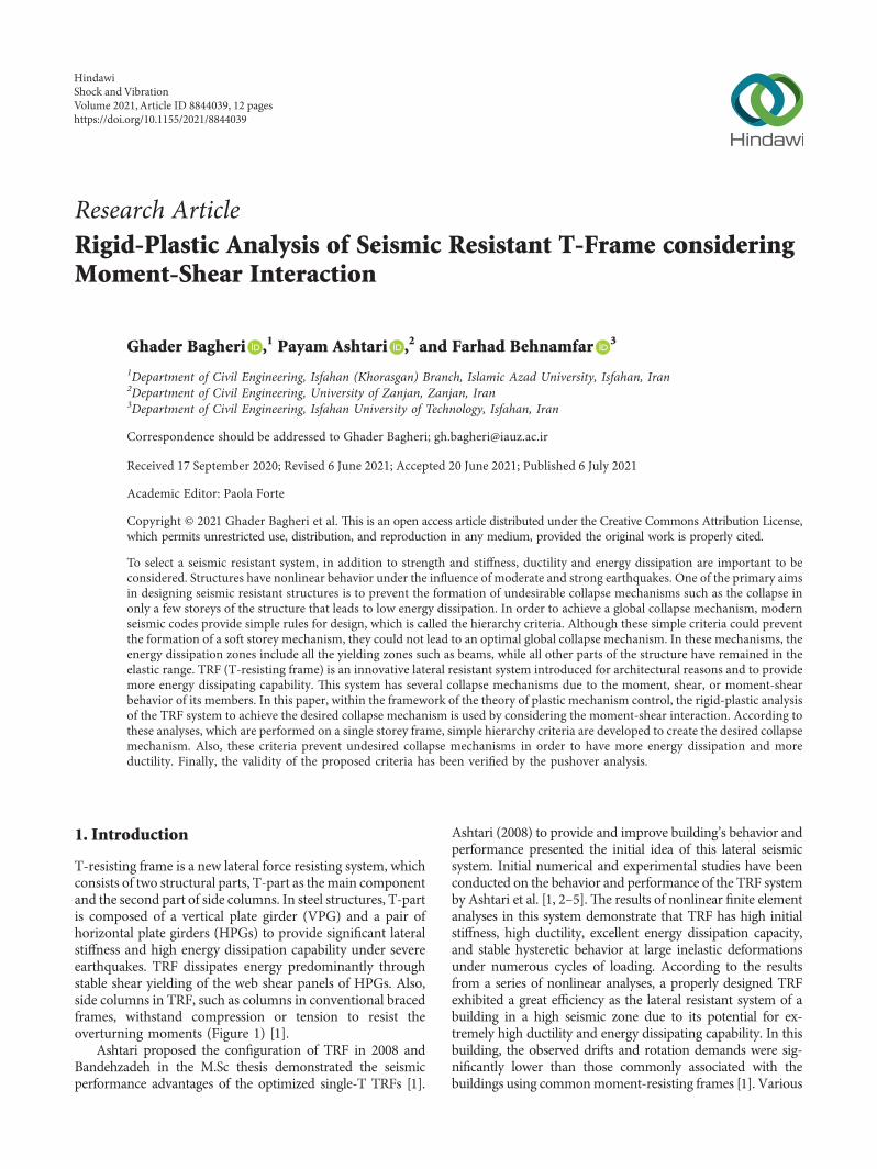
Model (I) shown in Figure 5(a) according to the resultsof Table 2 and analysis the collapse of the structure is inaccordance with the Mechanism ldquoArdquo In model (II) shown inFigure 5(b) according to the results of Table 2 and analysisthe collapse of the structure is in accordance with theMechanism ldquoBrdquo )e patterns obtained confirm the validityof the proposed design method
6 Conclusion
In this paper an analytical technique for considering theresults of moment and shear interaction on the TRF-Hsystemrsquos intermediate links has been presented )e wholeanalysis was carried out in the framework of the rigid-plasticdesign using plastic domain diagram normal flow rulekinematic compatibility and kinematic theory of plasticcollapse to have a strong theoretical basis In particular theanalytical relationships for the assessment of internal forcesand the plastic deformation of intermediate links have beenprovided and the appropriate hierarchy criteria for theformation of the desired collapse mechanism have beenobtained
From the design point of view the effect of linkrsquos strainhardening can be considered by applying the moment andshear overstrength factor in the plastic domain )epresented relationships are valid in the homothetic andnonhomothetic expansion of the plastic domain to de-termine the desired ultimate domain )e results obtainedare required as a strong and applied theory in the capacitydesign principles for seismic design of TRF-H systems Inaddition the resultant hierarchy criteria lead to the de-velopment of a design method for failure mode control inmultistorey TRF-H systems )is means that the final aimof the presented research is to ensure that a specificcollapse mechanism has an expected yield hierarchy forthe TRF-H system
Data Availability
)is article is based on mathematical relations Modeling iscompared with the results of mathematical relations and itsdata are available on request from the authors
Conflicts of Interest
)e authors declare that they have no conflicts of interest
References
[1] M Bandehzadeh and P Ashtari ldquoT-resisting frame conceptheadway towards seismic performance improvement of steelframerdquo Journal of Constructional Steel Research vol 104pp 193ndash205 2015
[2] Bandehzadeh ldquoEvaluation of nonlinear behavior of steelbuildings using deep beams as the lateral resistant system T-braced framerdquo MSc thesis Department of Civil EngineeringUniversity of Zanjan Zanjan Iran in Persian 2009
[3] M Gorzin R Tajmir and P Ashtari ldquoEvaluation of en-durance time method in seismic assessment of lateralT-resistingrdquo Sharif Journal Civil Engineering vol 2-31 no 11 pp 199ndash128 2014
[4] P Ashtari H Barzegar and F Hamedi ldquoExperimental andnumerical study on innovative seismic T-resisting frame(TRF)rdquo Journal Structural Engineering andMechanics vol 60no 2 pp 251ndash269 2016
[5] P Ashtari H Barzegar and F Hamedi ldquoExperimental andnumerical evaluation of innovated T-resisting frames withhaunched horizontal plate girdersrdquo Journal Advances inStructural Engineering vol 23 no 8 2020
[6] CEN EN 1998-1-1 Eurocode 8-design of Structures forEarthquake Resistance Part 1 General Rules Seismic Actionsand Rules for Buildings Committee European de Normal-isation CENTC 250 Brussels Belgium 2005
[7] M Bruneau C M Uang and A Whittaker Ductile Design ofSteel Structures McGraw Hill Professional New York NYUSA 1997
[8] C W Roeder and E P Popov ldquoEccentrically braced steelframes for earthquakesrdquo Journal of the Structural Divisionvol 104 no 3 pp 391ndash412 1978
[9] K D Hjelmstad and E P Popov ldquoCyclic behavior and designof link beamsrdquo Journal of Structural Engineering vol 109no 10 pp 2387ndash2403 1983
[10] K Kasai and E P Popov ldquoGeneral behavior of WF steel shearlink beamsrdquo Journal of Structural Engineering vol 112 no 2pp 362ndash382 1986
[11] T Balendra M-T Sam C-Y Liaw and S-L Lee ldquoPrelim-inary studies into the behaviour of knee braced frames subjectto seismic loadingrdquo Engineering Structures vol 13 no 1pp 67ndash74 1991
[12] D C Rai and B J Wallace ldquoAluminium shear-links forenhanced seismic resistancerdquo Earthquake Engineering ampStructural Dynamics vol 27 no 4 pp 315ndash342 1998
[13] P Dusicka AM Itani and I G Buckle ldquoEvaluation ofconventional and specialty steels in shear link hystereticenergy dissipatersrdquo in Proceedings of the 13th WCEE Van-couver Canada August 2004
[14] L Mastrandrea R Montuori and V Piluso ldquoShear-momentinteraction in plastic design eccentrically braced framesrdquo inProceedings of the 4th International Conference on Behavior ofSteel Structures in Seismic Areas Naples Italy June 2003
[15] R Montuori E Nastri and V Piluso ldquoRigid-plastic analysisand moment-shear interaction for hierarchy criteria ofinverted Y EB-framesrdquo Journal of Constructional Steel Re-search vol 95 pp 71ndash80 2014
[16] L Mastrandrea R Montuori and V Piluso ldquoFailure modecontrol of seismic resistant EB framesrdquo in Proceedings of the
Table 2 )e results of the moment-shear interaction and deter-mining the type of mechanism
Model (I) Model (II)
x(A)BL 09677 09398
x(A)BR 09981 09972
x(A)AB 09781 09653
x(B)AB 09759 09826
x(A)BL + x
(A)BR + z middot x
(A)AB 41193 30348
2z middot x(B)AB 42970 22351
Mechanism (A) (B)
Shock and Vibration 11
4th International Conference on Behavior of Steel Structures inSeismic Areas NAPLES Naples Italy June 2003
[17] MA Conti L Mastrandrea and V Piluso ldquoPlastic design andseismic response of knee braced framesrdquo Advance SteelConstruction vol 5 no 3 pp 343ndash366 2009
[18] M T Giugliano A Longo R Montuori and V PilusoldquoFailure mode and drift control of MRF-CBF dual systemsrdquoe Open Construction amp Building Technology Journal vol 4no 1 pp 121ndash133 2010
[19] A Longo R Montuori and V Piluso ldquo)eory of plasticmechanism control of dissipative truss moment framesrdquoEngineering Structures vol 37 pp 63ndash75 2012
[20] R Montuori E Nastri and V Piluso ldquo)eory of plasticmechanism control for MRF-EBF dual systems closed formsolutionrdquo Engineering Structures vol 118 pp 287ndash306 2016
[21] R Montuori E Nastri and V Piluso ldquoSeismic response ofEB-frames with inverted Y-scheme TPMC versus Eurocodeprovisionsrdquo Earthquakes and Structures vol 8 no 5pp 1191ndash1214 2015
[22] T Okazaki M D Engelhardt M Nakashima and K SuitaldquoExperimental study on link to column connections in steeleccentrically braced framesrdquo in Proceedings of the 13th WorldConference on Earthquake Engineering Vancouver CanadaAugust 2004
[23] AISC Seismic Provisions for Structural Steel BuildingsAmerican Institute of Steel Construction Standard ANSIAISC 341-10 Chicago IL USA 2010
[24] T Okazaki M D Engelhardt A Drolias E SchellJ-K Hong and C-M Uang ldquoExperimental investigation oflink-to-column connections in eccentrically braced framesrdquoJournal of Constructional Steel Research vol 65 no 7pp 1401ndash1412 2009
[25] B G Neal ldquoEffect of shear force on the fully plastic moment ofan I-beamrdquo Journal of Mechanical Engineering Science vol 3no 3 pp 258ndash266 1961
[26] K D Hjelmstad and E P Popov ldquoSeismic behavior of activebeam link in eccentrically braced framesrdquo EERC Report No83-15 Earthquake Engineering Research Center Universityof California Berkeley CA USA 1983
[27] J O Malley and E P Popov ldquoDesign consideration for shearlinks in eccentrically braced framesrdquo EERC Report No 83-24Earthquake Engineering Research Center University ofCalifornia Berkeley CA USA 1983
[28] CEN EN 1993-1-1 Eurocode 3 Design of Steel Structures Part1 General Rules and Rules for Buildings Committee Europeande Normalization CENTC 250 Brussels Belgium 2005
[29] E P Popov and M D Engelhardt ldquoSeismic eccentricallybraced framesrdquo Journal of Constructional Steel Researchvol 10 pp 321ndash354 1988
[30] G Della Corte M DrsquoAniello and R Landolfo ldquoAnalytical andnumerical study of plastic overstrength of shear linksrdquo Journalof Constructional Steel Research vol 82 pp 19ndash32 2013
[31] E Barecchia G Della Corte and F M Mazzolani ldquoPlasticover-strength of short and intermediate linksrdquo in Proceedingsof the STESSA 2006 Conference on Behavior of Steel Structuresin Seismic Areas pp 177ndash183 Yokohama Japan August 2006
[32] American Association of State and Highway TransportationOfficials AASHTO AASHTO LRFD Bridge DesignSpecifications AASHTO Washington DC USA 2nd edition1998
[33] American Institute of Steel Construction (AISC) Load andResistance Factor Design Specification for Structural SteelBuildings American Institute of Steel Construction ChicagoIL USA 1999
[34] M D Engelhardt and E P Popov ldquoBehavior of long links ineccentrically braced framesrdquo EERC Report No 89-01Earthquake Engineering Research Center University ofCalifornia Berkeley CA USA 1989
[35] CSI SAP Integrated finite Element Analysis and Design ofStructures Analysis Reference Computer and Structure IncUniversity of California Berkeley CA USA 2000
12 Shock and Vibration

numerical studies and laboratory tests have been performed ondifferent configurations of this system )e results show thatthis system has good seismic behavior )e results show thatthis system has high initial stiffness high ductility excellentenergy dissipation capacity and stable hysteretic behavior atlarge inelastic deformations under numerous cycles of loading[4 5]
In the capacity design the energy dissipation zonesshould be designed according to the internal forces resultingfrom the load combinations provided by the seismic codes)e other parts of the structure have to be designed pro-portionally to the force of the energy dissipation zones Itmeans that these parts do not yield under the maximuminternal reactions transmitted by the energy dissipationzones in the fully yielded state [6 7]
In the eccentrically braced frames dissipative zones areconstituted by the members called link elements [8ndash10] )euse of members as energy dissipation zones which they areyielding in shear was originally proposed for eccentricallybraced frames )is issue has been the starting point for theformation of new structural types such as knee braces [11]aluminum shear links [12] and shear links made of low-flowpoint steel [13] Shear yielding is separated from the energydissipation due to moment yielding so the moment-shearinteraction could not be neglected
In this paper the TRF-H system has been studied inwhich the task of energy dissipation is assigned to the T-partmembers as link elements which are affected by momentshear or moment-shear interaction )e problem of mo-ment-shear interaction is considered within the frameworkof rigid-plastic analysis and the solution for the TRF-Hsystem is presented Solving the interaction problem is af-fected by compatibility conditions which depend on theconfiguration of the structure Such issue is currently beingstudied for eccentrically braced frames with D-schemeK-scheme V-scheme inverted V-scheme [14] and Y EB-
Frames [15] and here for the T-resisting frame system )epurpose of developing the hierarchy criteria is to control theyielding pattern Investigations are focused on the one-storey TRF-H system to determine which members and howthey yield )is theory is based on the rigid-plastic analysiswith the purpose of achieving the global collapse mecha-nism in which all the dissipation zones are yielding whilethe other members stay in the elastic range )is theory hasbeen presented for frames with horizontal link beam [16]knee braces (KB-frame) [17] dual MRF-CBF systems [18]and truss moment frame (DTMFs) [19] Also the solution ofthe theory of plastic mechanism control (TPMC) currentlybeing studied in the case of moment-resisting frames ec-centrically braced frames (MRF-EBF) dual systems [20] andeccentrically braced frames with inverted Y-scheme [21])ese studies provide a complete and exhaustive designprocedure for MRF-EBF dual systems and EB-frames withinverted Y-scheme considering all the brace configurationscommonly adopted and with the goal of assuring the de-velopment of a collapse mechanism of global type [20 21]
In Section 2 the study of moment-shear interaction inthe TRF-H system and the development of the hierarchycriteria at the storey level have been studied To assess theaccuracy of the proposed hierarchy criteria for the TRF-Hsystem has been examined by means of static pushoveranalyses with the SAP2000 computer program In additionthe theory of controlling plastic mechanisms for the mul-tistorey TRF system and fixedmultistorey TRF systemwouldbe provided in subsequent papers
2 The PlasticMechanisms in the TRF-H System
Independent from the configuration of the structure themain feature of the links is due to the interaction between thebending moment and the shear force which could not beignored in predicting the ultimate behavior of the structural
HPG HPG
Com
posit
es
colu
mn
VPG
HPG HPG
RC si
deco
lum
n
RC w
all
HPG HPG
Side
colu
mn
Vtr
uss
HPG HPG
Side
colu
mn
Side
colu
mn
VPG
HPG HPG
Side
colu
mn
VPG
HPG HPGSi
deco
lum
n
VPG
Side
colu
mn
Side
colu
mn
Side
colu
mn
VPG
VPG
HPG HPG HPG
Side
colu
mn
HPG HPG HPG
Side
colu
mn
VPG
VPG
VPG
(a)
(d) (e) (f) (g) (h)
(b) (c)
Figure 1 Proposed basic structural configurations of TRF and alternatives [1] (a) Single-T configuration of TRF (b) Double-T con-figuration of TRF (c) Multi-T configuration of TRF (d) Stylish single-T configuration of TRF (e) Stylish single-T configuration of TRF(f ) Single-T configuration of TRF using vertical truss (g) Single-T configuration of TRF using composite side columns (h) Single-Tconfiguration of reinforced concrete TRF
2 Shock and Vibration
system Generally the classification of the link beams de-pends on the length of the member In the following generalclassification is proposed [7ndash10]
(i) Short link for ele 16MPVP
(ii) Intermediate link for 16MPVP le ele 3MPVP
(iii) Long links for ege 3MPVP
Vp and Mp respectively are plastic shear strength andbending strength of the cross section of the link beam )elong link beam is considered to be in frequent revisions as26MPVP [22ndash24] Moment-shear interaction diagram andthe short medium and long linksrsquo range are shown inFigure 2
)e plastic behavior of the link beam for a bendingmoment less than Mf could be considered as a pure shearwhere Mf is the flange contribution of the plastic moment ofthe link beam thus for moments greater than Mf the shearstrength of the element is reduced due to the interactionbetween moment and shear According to Neal research theplastic zone is calculated using the following relationships[14 25]
|M| minus Mf
Mp minus Mf
1113888 1113889
2
+V
Vp
1113888 1113889
2
1 forMf le |M|leMP (1)
V Vp for|M|leMf (2)
In capacity design an important issue that has beenreported in previous experiments by Hjelmstad and Popov[26] and Malley and Popov [27] is the overstrength de-veloped by the link beam Overstrength of the link beam isthe ratio between the maximum shear forces developed bythe link beam to its plastic shear strength )e evaluation ofthe results of experiments is usually based on the inclusionof the plastic shear strength as VP 06fy(d minus tf)tw wherefy is the yield stress d is the depth of the cross section ofthe beam and tf and tw are the thickness of the flange andthe web respectively However the link overstrength oc-curs due to the strain hardening and the contribution oflink flanges to the shear strength )erefore according toEuropean codes [28] plastic shear strength is calculatedusing the web surface shear strength with the contributionof the flange
According to the capacity design the link overstrengthshould be calculated in the assessment of the maximuminternal forces transferred to the nonplastic elements )elink overstrength factor is generally recommended as 150based on previous experimental studies [29] In the 2005AISC seismic provisions [23] the link overstrength factor isproposed equal to 125 for designing the diagonal bracesand equal to 110 for designing columns and the beamoutside the link A similar approach has been adopted inthe eurocode [6] Recent experimental results and inves-tigations are indicated that overstrength factors can beexceeding the code suggested values For very short linkswith compact cross-sections and perfect axial restraintsvalues of shear overstrength up to 2 have been obtainedFor built-up links with a very compact shape and short
length even larger values could be obtained especially iflarger rotation capacity is achievable [30] Barecchia et alby means of finite element analyses on standard Europeanrolled profiles have found overstrength factors between200 and 250 for a link shear deformation equal to 010 rad[31] Nevertheless in using the above results some cautionshould be adopted because they come from finite elementanalyses where the stiffenersrsquo influence cannot be calculatedaccurately
Recently Okazaki et al based on several experimentaltests on shear links with properly detailed web stiffenerhave obtained the overstrength factor between 134 and148 for short links and in the range of 112ndash128 for longerlinks [24] )ese experimental results of the overstrengthfactor have been computed considering the measuredvalues of the material properties )erefore based on theseexperimental results it was concluded that the overstrengthfactor of 150 which forms worldwide the basis of capacitydesign provisions for EB-frames and appears reasonable forlinks made from rolled profiles A simple method forcalculating the overstrength of the hierarchy criteria ob-tained by the rigid-plastic analysis has recently been pre-sented [14] It is based on the use of the interaction domainreferring to the ultimate conditions obtained from thehomothetic or nonhomothetic expansion of the plasticdomain (Figure 2)
)e topologies of the plastic collapse mechanisms of theone-storey TRF-H are shown in Figure 3 In the type ldquoArdquomechanism ends of the both horizontal links and thebottom of the central column yield In mechanism ldquoBrdquo twoends of the central column yield Type of collapse mecha-nism is determined by the elements and structure specifi-cation)e aim of the research presented here is to define thehierarchy criteria which includes the effect of the moment-shear interaction to ensure that the desired mechanismwould be developed
In fact in order to calculate the moment and shearinteraction in the framework of rigid-plastic analysis theend-link yield is modeled with a combination of a pair ofplastic double pendulum and a plastic hinge that can
0
1
0 1
Short link
Long link
Intermediatelink
p
Plastic domain
Nonhomotheticexpanded domain
MMp
Ωmmiddotp Ωm
VV p
Ωv
sv
Ωvmiddotsv
(Ωm = Ωv)
Ultimate domain
Homotheticexpandeddomain
Figure 2 Moment-shear interaction diagram (p MfMp)
Shock and Vibration 3
calculate both types of plastic shear deformation ]P andmoment plastic rotation ϕp respectively
Use of the rigid-plastic analysis to calculate the plasticstrength of possible mechanisms needs to determine theplastic deformations of the links ]P and ϕp Also the valuesof shear force V and corresponding moment M for a givenvalue of the θ parameter is needed Problem solving could bedone by minimizing the internal work of the link and ap-plying the yielding conditions and considering of the normalplastic flow rule Additionally compatibility conditionsshould be satisfied
3 Moment-Shear Interaction in TRF-HSystem Elements
In the equations the index of parameters is based on thememberrsquos names meaning the BL and BR indexes are related
to the left and right horizontal link (beam) respectively andthe AB is related to the vertical member (central column)
31 Mechanism Type ldquoArdquo Within the framework of rigid-plastic analysis moment-shear interaction occurring in thelink of EB-frames is provided in the prior studies [15] )emoment and shear interaction in the elements of the TRF-Hframe (Figure 3(a)) within the framework of the rigid-plastic analysis is obtained by the following relationships(equations (3)ndash(10))
(1) Minimizing the internal work Wi according to thecollapse mechanism under the influence of theplastic rotation θ at the columns for a hinge state is
Min W(A)i M
(A)BL ϕ(A)
pBL + ϕ(A)pAB1113872 1113873 + V
(A)BL v
(A)pBL + M
(A)BR ϕ(A)
pBR + ϕ(A)pAB1113872 1113873 + V
(A)BR v
(A)pBR + M
(A)AB ϕ
(A)pAB + V
(A)AB v
(A)pAB (3)
(2) Kinematic compatibility conditions are
v(A)pBL + ϕ(A)
pBLeL 0 (4)
v(A)pBR + ϕ(A)
pBReR 0 (5)
v(A)pAB + ϕ(A)
pABh θh (6)
(3) Elementsrsquo yield condition leads to these threefunctions
F M(A)BL V
(A)BL1113872 1113873
M(A)BL
11138681113868111386811138681113868
11138681113868111386811138681113868 minus Mfb
Mpb minus Mfb
⎛⎝ ⎞⎠
2
+V
(A)BL
Vpb
1113888 1113889
2
minus 1
(7)
F M(A)BR V
(A)BR1113872 1113873
M(A)BR
11138681113868111386811138681113868
11138681113868111386811138681113868 minus Mfb
Mpb minus Mfb
⎛⎝ ⎞⎠
2
+V
(A)BR
Vpb
1113888 1113889
2
minus 1
(8)
F M(A)AB V
(A)AB1113872 1113873
M(A)AB
11138681113868111386811138681113868
11138681113868111386811138681113868 minus Mfc
Mpc minus Mfc
⎛⎝ ⎞⎠
2
+V
(A)AB
Vpc
1113888 1113889
2
minus 1
(9)
(4) Normal plastic flow law gives
v(A)p λ
zF
zV(A)
ϕ(A)p λ
zF
zM(A)
(10)
HereM(A)and V(A) are themoment and the shear formedat the end of TRF-H elements respectively ϕ(A)
P and ](A)P are
the plastic rotation and plastic shear deformation occurring inthe mechanism ldquoArdquo respectively e is length of the link h isheight of the storey and θ is the plastic rotation at the end of thebeam and columns )e ldquobrdquo and ldquocrdquo index are for the TRF-Hhorizontal link beam and central column respectively For each
Δ
θ
pBL
pBR
pAB
vpBL
vpAB
vpBR
(a)
θ
Δ
pAB
vpAB
vpAB
(b)
Figure 3 Modeling TRF-H system by considering the moment and shear interaction (a) Mechanism ldquoArdquo (b) Mechanism ldquoBrdquo
4 Shock and Vibration
member of the TRF-H system the values of the shear and themoment would be determined using the above equations)ese calculations aremade for the left horizontal link (BL) theright horizontal link (BR) and the central column of the TRF-H (AB) system For the BL member by substituting equations(4)ndash(6) into equation (3) an equation will be obtained thatexpresses the internal work as a function of the plastic rotationof the T-partrsquos members (ϕp) So minimizing the internal workof each member could be expressed as
dW(A)i
dϕ(A)pBL
0⟶ V(A)BL
M(A)BL
eL
(11)
dW(A)i
dϕ(A)pBR
0⟶ V(A)BR
M(A)BR
eR
(12)
dW(A)i
dϕ(A)pAB
0⟶ V(A)AB
M(A)BL + M
(A)BR + M
(A)AB
h (13)
By defining the plastic moment of the web as Mw
(Mw Mp + Mf) and by combining equations (7)ndash(9) withequations (11)ndash(13) for all T-part members the value ofM(A) and V(A) could be determined
)e value of M(A) and V(A) for the left horizontal link(BL) is determined as follows
M(A)BL
Mfb + Mwb
1 minus M2fb minus M
2wb1113872 1113873V2
pbe2L1113872 1113873
1113969
1 + M2wbV
2pbe
2L1113872 1113873
(14)
V(A)BL
Mfb + Mwb
1 minus M2fb minus M
2wb1113872 1113873V2
pbe2L1113872 1113873
1113969
eL 1 + M2wbV
2pbe
2L1113872 11138731113872 1113873
(15)
By defining the parameter pb MfbMpb the momentscan be rewritten based on the beamrsquos plastic momentAccordingly by substituting the values of in Mfb pbMpb
and Mwb (1 minus pb)Mpb and Vpb (4(1 minus pb)3
radichwb)
Mpb into equation (14) the BL moment is defined as thebeam plastic moment coefficient as follows
M(A)BL x
(A)BL middot Mpb (16)
V(A)BL
x(A)BL
eL
middot Mpb (17)
In these equations the multiplier x(A)BL is equal to
x(A)BL
pb + 1 minus pb( 1113857
1 minus (316) hwbeL1113872 11138732
2pb minus 1( 1113857 1 minus pb( 11138572
1113872 1113873
1113970
1 +(316) hwbeL1113872 11138732 pb lex
(A)BL le 1 (18)
Using the above equations with the definition of theshear length in the form of ev MfbVpb for different shearvalues V
(A)BL svbVpb (Figure 1) link length and moment
factor (x(A)BL ) can be obtained as follows
eL pb + 1 minus pb( 1113857
1 minus s2b
1113969
pbsb
⎛⎜⎜⎝ ⎞⎟⎟⎠ev (19)
x(A)BL pb + 1 minus pb( 1113857
1 minus s2b
1113969
(20)
According to the above equations for svb 1 equations(19) and (20) conclude that eL ev and x
(A)BL pb respectively
Consequently using equation (16) we have M(A)BL Mfb
which indicates a short (shear) link In addition where
eL⟶infin equation (18) concludes that x(A)BL 1 So
according to equation (16) we would have M(A)BL Mpb and
equation (17) gives V(A)BL MpbeL which this state indicates
the long (moment) link Also the values of M(A)BL and V
(A)BL
could be determined simply by combining the equilibriumconditions in the link with the yielding condition In otherwords the solution obtained is also reliable in a static state sothat it provides the actual internal reactions under the yieldingconditions in moment-shear interactions
In addition using these equations and choosing thevalue of svb the length of the long link could also be de-termined According to AISC99 and AASHTO if this valueis considered 06 then we have [32 33]
em pb + 43pb
1113888 1113889ev
x(A)BL 02pb + 08
M(A)BL 02pb + 08( 1113857Mpb ⟶
0ltpb lt1M
(A)BL (08 sim 10)Mpb(long link)
⎧⎪⎪⎪⎪⎪⎪⎪⎪⎪⎪⎨
⎪⎪⎪⎪⎪⎪⎪⎪⎪⎪⎩
(21)
Shock and Vibration 5
In this relation em is defined as the length of moment(long) link
Also for the right beam (BR) it can be determined asfollows
M(A)BR
Mfb + Mwb
1 minus M2fb minus M
2wb1113872 1113873V2
pbe2R1113872 1113873
1113969
1 + M2wbV
2pbe
2R1113872 1113873
(22)
V(A)BR
Mfb + Mwb
1 minus M2fb minus M
2wb1113872 1113873V2
pbe2R1113872 1113873
1113969
eR 1 + M2wbV
2pbe
2R1113872 11138731113872 1113873
(23)
x(A)BR
pb + 1 minus pb( 1113857
1 minus (316) hwbeR1113872 11138732
2pb minus 1( 1113857 1 minus pb( 11138572
1113872 1113873
1113970
1 +(316) hwbeR1113872 11138732 (24)
M(A)BR x
(A)BR middot Mpb (25)
V(A)BR
x(A)BR
eR
middot Mpb (26)
In this case for a link with long length (eR⟶infin)according to equation (24) x
(A)BR 1 Consequently by using
equations (25) and (26) we have M(A)BR Mpb and
V(A)BR MpbeR respectively which indicates the long link
All the relations and conditions examined for the left link(BL) are confirmed for the right link (BR)
Finally for the central column (AB) by defining theparameter pc MfcMpc and by substituting the valuesMpc zMpb Mfc pcMpc Mwc (1 minus pc)Mpc andVpc ((4(1 minus pc))
3
radichwc)Mpc we have
M(A)AB x
(A)AB middot Mpc (27)
V(A)AB
x(A)BL + x
(A)BR + z middot x
(A)AB
z middot hmiddot Mpc
(28)
x(A)AB
pc minus x(A)BL + x
(A)BR1113872 1113873z1113872 1113873(316) hwch1113872 1113873
2
1 +(316) hwch1113872 11138732
1113874 1113875
+1 minus pc( 1113857
1 minus 2pc + x(A)BL + x
(A)BR1113872 1113873z1113872 1113873 x
(A)BL + x
(A)BR1113872 1113873z middot 1 minus pc( 1113857
21113872 1113873 + 2pc minus 1( 1113857 1 minus pc( 1113857
21113872 11138731113872 1113873(316) hwch1113872 1113873
21113969
1 +(316) hwch1113872 11138732
1113874 1113875
(29)
According to equation (27) moment of central column canbe defined as a coefficient of the column plastic moment(pc lex
(A)AB le 1) in collapse mechanism In this column by
substituting V(A)AB svcVpc into the above equations the
minimummoment link length (hm) can be obtained as follows
hm x(A)BL + x
(A)BR + z middot pc + 1 minus pc( 1113857
1 minus s2vc
1113969
1113874 11138751113874 1113875
middot
3
radichwc
4z middot 1 minus pc( 1113857 middot svc
(30)
6 Shock and Vibration
By using svc 1 in equation (30) maximum shear linklength (hv) can be obtained as
hv x(A)BL + x
(A)BR + z middot pc1113872 1113873
3
radichwc
4z middot 1 minus pc( 1113857 (31)
For h hv based on equation (29) x(A)AB pc and con-
sequently M(A)AB Mfc this state represents a short or shear
link Also for svc⟶ 0 equation (30) gives hm⟶infin andaccording to equation (29) we have x
(A)AB 1 and conse-
quently M(A)AB Mpc which indicates long link )is solution
is valid within the framework of the static approach so that itprovides actual internal reactions under yielding conditions inmoment-shear interaction and also it can evaluate the cor-responding plastic shear deformation ](A)
P and plastic rotationϕ(A)
P According to the normal plastic flow rule (equation (10))the plastic shear deformation ](A)
PAB and the plastic rotationϕ(A)
PAB for the central column can be obtained as follows
v(A)pAB 2λ
V(A)AB
V2pc
ϕ(A)pAB 2λ
M(A)AB minus Mfc
M2wc
(32)
where the parameter λ which is controlling the large plasticflow can be eliminated by dividing ϕ(A)
P and ](A)P By
combining resultant equation with the kinematic compat-ibility conditions (equation (6)) the plastic shear defor-mation of the central column ](A)
PAB and its plastic rotationϕ(A)
PAB can be obtained as follows
v(A)pAB θh
11 + M
(A)AB minus Mfb1113872 1113873M2
wb1113872 1113873 V2pbV
(A)AB1113872 11138731113872 1113873h
(33)
ϕ(A)pAB θ
11 + M
2wb M
(A)AB minus Mfb1113872 11138731113872 1113873 V
(A)AB V
2pbh1113872 1113873
(34)
Finally regarding this issue the internal work W(A)i can
be obtained by substituting equations (11)ndash(13) in equation(3) as follows
W(A)i M
(A)BL θ + M
(A)BR θ + M
(A)AB θ (35)
Equations (35) shows that in this type of mechanisminternal work in the beams and the central column of theTRF-H system can simply be expressed asWlink M(A)θ Mpmiddoteqθ where Mpmiddoteq is yielding momentconsidering shear-moment interaction that is between Mf
and Mp )is result means that M(A) can be interpreted asan equivalent plastic moment allowing to write the internalwork simply on the basis of the equivalent plastic momentand the equivalent plastic rotation even in the case ofmoment-shear interaction [14]
32MechanismType ldquoBrdquo )e relations required to solve theproblem of moment-shear interaction in the intermediatelinks for the Mechanism ldquoBrdquo are as follows
(1) Condition for minimizing internal work of the ldquoBrdquotype collapse mechanism under the influence of therotation θ can be expressed as
Min middot W(B)i 2M
(B)ABϕ
(B)pAB + 2V
(B)AB v
(B)pAB (36)
(2) Kinematic compatibility condition is
2v(B)pAB + ϕ(B)
pABh θh (37)
(3) Yielding condition of the link leads to the followingfunction
F M(B)AB V
(B)AB1113872 1113873
M(B)AB
11138681113868111386811138681113868
11138681113868111386811138681113868 minus Mfc
Mpc minus Mfc
⎛⎝ ⎞⎠
2
+V
(B)AB
Vpc
1113888 1113889
2
minus 1
(38)
(4) Normal plastic flow rule are as follows
v(B)p λ
zF
zV(B)
ϕ(B)p λ
zF
zM(B)
(39)
where M(B)AB and V
(B)AB are respectively the bending moment
and the shear created on the ends of the central column (AB)of the TRF-H system in the mechanism ldquoBrdquo ϕ(B)
P and ](B)P
respectively are plastic rotation and plastic shear defor-mation created at the two ends of central column For eachmember of the TRF-H system the values of the shear andmoment can be determined using the above relations Bysubstituting equation (37) into equation (36) the followingequation is obtained
W(B)i 2M
(B)ABϕ
(B)pAB + V
(B)AB hθ minus hΦ(B)
pAB1113872 1113873 (40)
For the certain value of θ the internal work relation canbe expressed as a function of the plastic rotation of end of thecolumns ϕ(B)
P So minimizing the internal work could beexpressed by
dW(B)i
dϕ(B)pAB
0⟶ V(B)AB
2M(B)AB
h (41)
By combining equation (38) with equation (41) theinternal reactions in the central column of the TRF-H systemcan be determined as follows
M(B)AB
Mfc + Mwc
1 minus 4 M2fc minus M
2wc1113872 1113873V2
pch2
1113872 1113873
1113969
1 + 4 M2wcV
2pch
21113872 1113873
(42)
V(B)AB 2
Mfc + Mwc
1 minus 4 M2fc minus M
2wc1113872 1113873V2
pch2
1113872 1113873
1113969
h 1 + 4 M2wcV
2pch
21113872 11138731113872 1113873
(43)
Shock and Vibration 7
Same asmechanism type ldquoArdquo by substitutingMfcMwcand Vpc into equations (42) and (43) the moment and shearvalue would be defined as a coefficient of the beam plasticmoment
M(B)AB x
(B)AB middot Mpc (44)
V(B)AB
2x(B)AB
hmiddot Mpc
(45)
where
x(B)AB
pc + 1 minus pc( 1113857
1 minus (34) hwch1113872 11138732
2pc minus 1( 1113857 1 minus pc( 11138572
1113872 1113873
1113970
1 +(34) hwch1113872 11138732 pc le x
(B)AB le 1 (46)
Using the above relations for the different shear valuesV svc middot Vpc the moment multiplier can be obtained asfollows
x(A)BL pb + 1 minus pb( 1113857
1 minus s2c
1113969
(47)
with respect to the above relation for a state where sc 1according to equation (47) we have x
(B)AB pc and conse-
quently using equation (44) M(B)AB Mfc this state indi-
cates a short link Also for state where sc⟶ 0 equation(47) would conclude that x
(B)AB 1 according to equation
(44) M(B)AB Mpc which indicates the long link
Same as mechanism ldquoArdquo plastic deformations ](B)P and
ϕ(B)P can be calculated at the ends of the link depending on
the kinematic conditions Using the normal plastic flow rulethe parameter λ which is controlling large plastic yieldcould be eliminated by dividing ϕ(B)
P and ](B)P )en by
combining resultant equation with the kinematic compat-ibility the plastic shear deformation of the central column](B)
PAB and its plastic rotation ϕ(B)PAB can be obtained as follows
ϕ(B)pAB θ
11 + 2M
2wc M
(B)AB minus Mfc1113872 11138731113872 1113873 V
(B)AB V
2pch1113872 1113873
(48)
v(B)pAB θh
12 + M
(B)AB minus Mfc1113872 1113873M2
wc1113872 1113873 V2pchV
(B)AB1113872 1113873
(49)
4 Hierarchy Criteria for TRF-H System
41 Hierarchy Criteria for Intermediate Link Beams In dif-ferent mechanisms three main elements of the TRF-Hsystem could be as short long or intermediate links )epurpose of this research is to develop the hierarchy criteriafor controlling the frame yield pattern of the one-storeyTRF-H system In the mechanism ldquoArdquo all three elements ofthe TRF-H system have been yielded In the mechanism ldquoBrdquoonly the yield of the central column of this system has beenconsidered According to the kinematic theory of plasticcollapse the condition to achieve desired collapse mecha-nism is that the kinetic external force for a mechanism ldquoArdquobecomes less than the one for mechanism ldquoBrdquo
)e internal virtual work is expressed for the mechanismldquoArdquo using equation (35) For the mechanism ldquoBrdquo W
(A)i can
be obtained by substituting equation (41) in equation (40) asfollows
B minus typemechanism W(B)i 2M
(B)AB θ (50)
External work is only due to the horizontal inertia forceof the earthquake and is obtained for both the mechanismsby the following equation
WeF Fextθh (51)
)e coefficient of horizontal kinematic force is obtainedby equating external work and internal work )erefore thefollowing relation is obtained
A minus typemechanism F(A)ext
M(A)BL + M
(A)BR + M
(A)AB
Fh (52)
B minus typemechanism F(B)ext
2M(B)AB
Fh (53)
Given equations (52) and (53) it is possible to write adesign criterion for the formation of the mechanism ldquoArdquobefore the mechanism ldquoBrdquo for which the following relationmust be satisfied
F(A)ext leF
(B)ext ⟶M
(A)BL + M
(A)BR + M
(A)AB le 2M
(B)AB (54)
Substituting equations (13) and (45) in equation (54)gives
V(A)AB leV
(B)AB (55)
In addition substituting equations (17) (26) (27) and(44) in equation (54) the following relation is obtained
x(A)BL + x
(A)BR + z middot x
(A)AB le 2z middot x
(B)AB (56)
42HierarchyCriteria forLongLinkBeams In long links theplastic shear deformation (vp) is negligible and is consideredzero )erefore the internal work of the kinematic mech-anisms discussed is easily obtained In its mechanism ldquoArdquo(Figure 2(a)) three members of the TRF-H system includinga two beams BL and BR and a column AB would yield Alsoin its mechanism ldquoBrdquo the central vertical member of theTRF-H (AB) system yields from both ends In accordance
8 Shock and Vibration
with equations (18) (24) (29) and (46) for elements indifferent mechanisms the value is plexle 1 In eachmember if the value x 1 the member is long and wouldhave a bending behavior Accordingly by substituting thisvalue in equation (56) for all the elements the criteria for thedifferent mechanism links can be obtained as follows
zge 2⟶Mpc ge 2Mpb (57)
43 Hierarchy Criteria for Short Link Beams In short linksthe moment and shear interaction according to Figure 2 isnegligible so only the shear plastic deformation is vp and thevalue of ϕp is zero according to the normal plastic flow ruleIn accordance with equations (18) (24) (29) and (46) foreach member in different mechanisms if the value is x pthe element is a short link and has shear behavior )ereforeby substituting this value in equation (56) the hierarchycriteria for the short links can be obtained as follows
z middot pc ge 2pb⟶Mfc ge 2Mfb (58)
5 Numerical Examples and Verification
In this section in order to verify the hierarchy criteriaobtained these criteria are considered for the one-storeyTRF-H frame with particular attention to intermediate linksin which the moment-shear interaction is important )einelastic behavior of the designed structure has been ex-amined with the pushover analysis to achieve the designgoals namely the desired mechanism
)e profile of the T-part elements is shown in Table 1)e steel used in these members is S235 (fyk 235MPa)
type In order to validate the hierarchy criteria provided withintermediate links two models are analyzed named model(I) and model (II)
In according to Eurocode 8 [1] links are classified asshort links that have the following length of link
ele 16Mplink
Vplink (59)
where Mplink Mf bftffy(d minus tf) and Vplink Vp
(d minus 2tf)twfy3
radicare plastic moment and plastic shear in
the link respectively It should be noted that in equation (59)due to strain hardening the flexural overstrength factor isabout 12 (Ωm) and the shear overstrength is equal to 15(Ωv) )erefore using the equilibrium equation in the linkthe maximum shear length in the ultimate state is as follows[34]
e 20Mu
Vu
20120Mplink
150Vplink 16
Mplink
Vplink (60)
where Mu and Vu are the ultimate moment and ultimateshear respectively Equation (60) is established for the linkshaving two end rigid connections In the TRF system withhinge connections this equation can be used for the centralcolumn but for the beams the multiplier 16 is replaced by08 Obviously these results could be easily generalized tothe ultimate state using shear and flexural overstrength asshown in Figure 2 With such an expansion of the plasticdomain to reach the ultimate domain all the relationshipsobtained in Sections 3 and 4 remain unchanged for theultimate values ofM and V Limitation provided by equation(60) for the elements of the TRF-H system with mentionedsections in Table 1 in model (I) for beam would be equal to048 meters in the ultimate state and 061 meters in theplastic state and for the central column of the TRF-H systemwould be equal to 151 meters in the ultimate state and 094meters in the plastic state In Model (II) for beam would beequal to 074 meters in the ultimate state and 093 meters inthe plastic state and for the central column of the TRF-Hsystem would be equal to 069 meters in the ultimate stateand 111 meters in the plastic state
In models (I) and (II) the span length is equal toL 50m the height of the storey is equal to h 30m andthe length of the left beam is considered in the TRF-H systemas an average link of 10m (eL 10m) )e moment-shearinteraction diagram for cross section of the TRF-H systemmembers is shown in Figure 4 In this figure BL and BRcorrespond to the yielding of the left and right beams of theTRF-H system and AB corresponds to the yielding of thecentral column of the TRF-H system
It should be noted that in design terms plastic momentsare reduced due to the effects of axial forces )is axial forcecould be easily calculated from the shear reaction resultstransmitted between the beam and the column of the TRF-Hsystem and balanced by the axial forces of these elements
To evaluate the validity of the hierarchy criteria previ-ously described various types of structures examinedaccording to Table 1 were analyzed using pushover analyzeswith the SAP2000 computer program [35] It should benoted that in the SAP2000 software the moment-shearinteraction could not be defined and the elements of theTRF-H system are modeled as a beam and column elementwith a plastic hinge at their ends in which the plasticmoment is equal to the plastic moment with the use ofrelationships in Section 4 has been determined )emechanisms developed for the models examined are shownin Figure 5 where structural deformation is shown that these
Table 1 Characteristics of used profile sections
Model Element sectionFlange plate Web plate
bf (mm) tf (mm) hw (mm) tw (mm)
(I) Beam (BL and BR) 200 10 20 6Column (AB) 200 20 200 8
(II) Beam (BL and BR) 200 15 200 6Column (AB) 200 15 200 8
Shock and Vibration 9
Beamsection-
model (I)
BL
BR
0
02
04
06
08
1
12
14
0 02 04 06 08 1 12 14 16
VV p
MMp
Short link
Long link
Intermediatelink
(a)
Columnsection-
model (I)
AB
0
02
04
06
08
1
12
14
0 02 04 06 08 1 12 14 16
VV p
MMp
Short link
Long link
Intermediatelink
(b)
Beamsection-
model (II)BL
BR
0
02
04
06
08
1
12
14
0 02 04 06 08 1 12 14 16
VV p
MMp
Short link
Long link
Intermediatelink
(c)
Columnsection-
model (II)
AB
0
02
04
06
08
1
12
14
0 02 04 06 08 1 12 14 16
VV p
MMp
Short link
Long link
Intermediatelink
(d)
Figure 4)emoment-shear interaction diagram for T-part elementsrsquo sections For the models studied the results of the relationships givenin Section 4 for determining the hierarchy criteria are shown in Table 2
(a) (b)
Figure 5 Results of analysis of models (I) and (II)
10 Shock and Vibration
deformations are for the displacement value which isarranged at the top of the storey to form a kinematicmechanism for all models examined and there is a completeassurance
Model (I) shown in Figure 5(a) according to the resultsof Table 2 and analysis the collapse of the structure is inaccordance with the Mechanism ldquoArdquo In model (II) shown inFigure 5(b) according to the results of Table 2 and analysisthe collapse of the structure is in accordance with theMechanism ldquoBrdquo )e patterns obtained confirm the validityof the proposed design method
6 Conclusion
In this paper an analytical technique for considering theresults of moment and shear interaction on the TRF-Hsystemrsquos intermediate links has been presented )e wholeanalysis was carried out in the framework of the rigid-plasticdesign using plastic domain diagram normal flow rulekinematic compatibility and kinematic theory of plasticcollapse to have a strong theoretical basis In particular theanalytical relationships for the assessment of internal forcesand the plastic deformation of intermediate links have beenprovided and the appropriate hierarchy criteria for theformation of the desired collapse mechanism have beenobtained
From the design point of view the effect of linkrsquos strainhardening can be considered by applying the moment andshear overstrength factor in the plastic domain )epresented relationships are valid in the homothetic andnonhomothetic expansion of the plastic domain to de-termine the desired ultimate domain )e results obtainedare required as a strong and applied theory in the capacitydesign principles for seismic design of TRF-H systems Inaddition the resultant hierarchy criteria lead to the de-velopment of a design method for failure mode control inmultistorey TRF-H systems )is means that the final aimof the presented research is to ensure that a specificcollapse mechanism has an expected yield hierarchy forthe TRF-H system
Data Availability
)is article is based on mathematical relations Modeling iscompared with the results of mathematical relations and itsdata are available on request from the authors
Conflicts of Interest
)e authors declare that they have no conflicts of interest
References
[1] M Bandehzadeh and P Ashtari ldquoT-resisting frame conceptheadway towards seismic performance improvement of steelframerdquo Journal of Constructional Steel Research vol 104pp 193ndash205 2015
[2] Bandehzadeh ldquoEvaluation of nonlinear behavior of steelbuildings using deep beams as the lateral resistant system T-braced framerdquo MSc thesis Department of Civil EngineeringUniversity of Zanjan Zanjan Iran in Persian 2009
[3] M Gorzin R Tajmir and P Ashtari ldquoEvaluation of en-durance time method in seismic assessment of lateralT-resistingrdquo Sharif Journal Civil Engineering vol 2-31 no 11 pp 199ndash128 2014
[4] P Ashtari H Barzegar and F Hamedi ldquoExperimental andnumerical study on innovative seismic T-resisting frame(TRF)rdquo Journal Structural Engineering andMechanics vol 60no 2 pp 251ndash269 2016
[5] P Ashtari H Barzegar and F Hamedi ldquoExperimental andnumerical evaluation of innovated T-resisting frames withhaunched horizontal plate girdersrdquo Journal Advances inStructural Engineering vol 23 no 8 2020
[6] CEN EN 1998-1-1 Eurocode 8-design of Structures forEarthquake Resistance Part 1 General Rules Seismic Actionsand Rules for Buildings Committee European de Normal-isation CENTC 250 Brussels Belgium 2005
[7] M Bruneau C M Uang and A Whittaker Ductile Design ofSteel Structures McGraw Hill Professional New York NYUSA 1997
[8] C W Roeder and E P Popov ldquoEccentrically braced steelframes for earthquakesrdquo Journal of the Structural Divisionvol 104 no 3 pp 391ndash412 1978
[9] K D Hjelmstad and E P Popov ldquoCyclic behavior and designof link beamsrdquo Journal of Structural Engineering vol 109no 10 pp 2387ndash2403 1983
[10] K Kasai and E P Popov ldquoGeneral behavior of WF steel shearlink beamsrdquo Journal of Structural Engineering vol 112 no 2pp 362ndash382 1986
[11] T Balendra M-T Sam C-Y Liaw and S-L Lee ldquoPrelim-inary studies into the behaviour of knee braced frames subjectto seismic loadingrdquo Engineering Structures vol 13 no 1pp 67ndash74 1991
[12] D C Rai and B J Wallace ldquoAluminium shear-links forenhanced seismic resistancerdquo Earthquake Engineering ampStructural Dynamics vol 27 no 4 pp 315ndash342 1998
[13] P Dusicka AM Itani and I G Buckle ldquoEvaluation ofconventional and specialty steels in shear link hystereticenergy dissipatersrdquo in Proceedings of the 13th WCEE Van-couver Canada August 2004
[14] L Mastrandrea R Montuori and V Piluso ldquoShear-momentinteraction in plastic design eccentrically braced framesrdquo inProceedings of the 4th International Conference on Behavior ofSteel Structures in Seismic Areas Naples Italy June 2003
[15] R Montuori E Nastri and V Piluso ldquoRigid-plastic analysisand moment-shear interaction for hierarchy criteria ofinverted Y EB-framesrdquo Journal of Constructional Steel Re-search vol 95 pp 71ndash80 2014
[16] L Mastrandrea R Montuori and V Piluso ldquoFailure modecontrol of seismic resistant EB framesrdquo in Proceedings of the
Table 2 )e results of the moment-shear interaction and deter-mining the type of mechanism
Model (I) Model (II)
x(A)BL 09677 09398
x(A)BR 09981 09972
x(A)AB 09781 09653
x(B)AB 09759 09826
x(A)BL + x
(A)BR + z middot x
(A)AB 41193 30348
2z middot x(B)AB 42970 22351
Mechanism (A) (B)
Shock and Vibration 11
4th International Conference on Behavior of Steel Structures inSeismic Areas NAPLES Naples Italy June 2003
[17] MA Conti L Mastrandrea and V Piluso ldquoPlastic design andseismic response of knee braced framesrdquo Advance SteelConstruction vol 5 no 3 pp 343ndash366 2009
[18] M T Giugliano A Longo R Montuori and V PilusoldquoFailure mode and drift control of MRF-CBF dual systemsrdquoe Open Construction amp Building Technology Journal vol 4no 1 pp 121ndash133 2010
[19] A Longo R Montuori and V Piluso ldquo)eory of plasticmechanism control of dissipative truss moment framesrdquoEngineering Structures vol 37 pp 63ndash75 2012
[20] R Montuori E Nastri and V Piluso ldquo)eory of plasticmechanism control for MRF-EBF dual systems closed formsolutionrdquo Engineering Structures vol 118 pp 287ndash306 2016
[21] R Montuori E Nastri and V Piluso ldquoSeismic response ofEB-frames with inverted Y-scheme TPMC versus Eurocodeprovisionsrdquo Earthquakes and Structures vol 8 no 5pp 1191ndash1214 2015
[22] T Okazaki M D Engelhardt M Nakashima and K SuitaldquoExperimental study on link to column connections in steeleccentrically braced framesrdquo in Proceedings of the 13th WorldConference on Earthquake Engineering Vancouver CanadaAugust 2004
[23] AISC Seismic Provisions for Structural Steel BuildingsAmerican Institute of Steel Construction Standard ANSIAISC 341-10 Chicago IL USA 2010
[24] T Okazaki M D Engelhardt A Drolias E SchellJ-K Hong and C-M Uang ldquoExperimental investigation oflink-to-column connections in eccentrically braced framesrdquoJournal of Constructional Steel Research vol 65 no 7pp 1401ndash1412 2009
[25] B G Neal ldquoEffect of shear force on the fully plastic moment ofan I-beamrdquo Journal of Mechanical Engineering Science vol 3no 3 pp 258ndash266 1961
[26] K D Hjelmstad and E P Popov ldquoSeismic behavior of activebeam link in eccentrically braced framesrdquo EERC Report No83-15 Earthquake Engineering Research Center Universityof California Berkeley CA USA 1983
[27] J O Malley and E P Popov ldquoDesign consideration for shearlinks in eccentrically braced framesrdquo EERC Report No 83-24Earthquake Engineering Research Center University ofCalifornia Berkeley CA USA 1983
[28] CEN EN 1993-1-1 Eurocode 3 Design of Steel Structures Part1 General Rules and Rules for Buildings Committee Europeande Normalization CENTC 250 Brussels Belgium 2005
[29] E P Popov and M D Engelhardt ldquoSeismic eccentricallybraced framesrdquo Journal of Constructional Steel Researchvol 10 pp 321ndash354 1988
[30] G Della Corte M DrsquoAniello and R Landolfo ldquoAnalytical andnumerical study of plastic overstrength of shear linksrdquo Journalof Constructional Steel Research vol 82 pp 19ndash32 2013
[31] E Barecchia G Della Corte and F M Mazzolani ldquoPlasticover-strength of short and intermediate linksrdquo in Proceedingsof the STESSA 2006 Conference on Behavior of Steel Structuresin Seismic Areas pp 177ndash183 Yokohama Japan August 2006
[32] American Association of State and Highway TransportationOfficials AASHTO AASHTO LRFD Bridge DesignSpecifications AASHTO Washington DC USA 2nd edition1998
[33] American Institute of Steel Construction (AISC) Load andResistance Factor Design Specification for Structural SteelBuildings American Institute of Steel Construction ChicagoIL USA 1999
[34] M D Engelhardt and E P Popov ldquoBehavior of long links ineccentrically braced framesrdquo EERC Report No 89-01Earthquake Engineering Research Center University ofCalifornia Berkeley CA USA 1989
[35] CSI SAP Integrated finite Element Analysis and Design ofStructures Analysis Reference Computer and Structure IncUniversity of California Berkeley CA USA 2000
12 Shock and Vibration

Beamsection-
model (I)
BL
BR
0
02
04
06
08
1
12
14
0 02 04 06 08 1 12 14 16
VV p
MMp
Short link
Long link
Intermediatelink
(a)
Columnsection-
model (I)
AB
0
02
04
06
08
1
12
14
0 02 04 06 08 1 12 14 16
VV p
MMp
Short link
Long link
Intermediatelink
(b)
Beamsection-
model (II)BL
BR
0
02
04
06
08
1
12
14
0 02 04 06 08 1 12 14 16
VV p
MMp
Short link
Long link
Intermediatelink
(c)
Columnsection-
model (II)
AB
0
02
04
06
08
1
12
14
0 02 04 06 08 1 12 14 16
VV p
MMp
Short link
Long link
Intermediatelink
(d)
Figure 4)emoment-shear interaction diagram for T-part elementsrsquo sections For the models studied the results of the relationships givenin Section 4 for determining the hierarchy criteria are shown in Table 2
(a) (b)
Figure 5 Results of analysis of models (I) and (II)
10 Shock and Vibration
deformations are for the displacement value which isarranged at the top of the storey to form a kinematicmechanism for all models examined and there is a completeassurance
Model (I) shown in Figure 5(a) according to the resultsof Table 2 and analysis the collapse of the structure is inaccordance with the Mechanism ldquoArdquo In model (II) shown inFigure 5(b) according to the results of Table 2 and analysisthe collapse of the structure is in accordance with theMechanism ldquoBrdquo )e patterns obtained confirm the validityof the proposed design method
6 Conclusion
In this paper an analytical technique for considering theresults of moment and shear interaction on the TRF-Hsystemrsquos intermediate links has been presented )e wholeanalysis was carried out in the framework of the rigid-plasticdesign using plastic domain diagram normal flow rulekinematic compatibility and kinematic theory of plasticcollapse to have a strong theoretical basis In particular theanalytical relationships for the assessment of internal forcesand the plastic deformation of intermediate links have beenprovided and the appropriate hierarchy criteria for theformation of the desired collapse mechanism have beenobtained
From the design point of view the effect of linkrsquos strainhardening can be considered by applying the moment andshear overstrength factor in the plastic domain )epresented relationships are valid in the homothetic andnonhomothetic expansion of the plastic domain to de-termine the desired ultimate domain )e results obtainedare required as a strong and applied theory in the capacitydesign principles for seismic design of TRF-H systems Inaddition the resultant hierarchy criteria lead to the de-velopment of a design method for failure mode control inmultistorey TRF-H systems )is means that the final aimof the presented research is to ensure that a specificcollapse mechanism has an expected yield hierarchy forthe TRF-H system
Data Availability
)is article is based on mathematical relations Modeling iscompared with the results of mathematical relations and itsdata are available on request from the authors
Conflicts of Interest
)e authors declare that they have no conflicts of interest
References
[1] M Bandehzadeh and P Ashtari ldquoT-resisting frame conceptheadway towards seismic performance improvement of steelframerdquo Journal of Constructional Steel Research vol 104pp 193ndash205 2015
[2] Bandehzadeh ldquoEvaluation of nonlinear behavior of steelbuildings using deep beams as the lateral resistant system T-braced framerdquo MSc thesis Department of Civil EngineeringUniversity of Zanjan Zanjan Iran in Persian 2009
[3] M Gorzin R Tajmir and P Ashtari ldquoEvaluation of en-durance time method in seismic assessment of lateralT-resistingrdquo Sharif Journal Civil Engineering vol 2-31 no 11 pp 199ndash128 2014
[4] P Ashtari H Barzegar and F Hamedi ldquoExperimental andnumerical study on innovative seismic T-resisting frame(TRF)rdquo Journal Structural Engineering andMechanics vol 60no 2 pp 251ndash269 2016
[5] P Ashtari H Barzegar and F Hamedi ldquoExperimental andnumerical evaluation of innovated T-resisting frames withhaunched horizontal plate girdersrdquo Journal Advances inStructural Engineering vol 23 no 8 2020
[6] CEN EN 1998-1-1 Eurocode 8-design of Structures forEarthquake Resistance Part 1 General Rules Seismic Actionsand Rules for Buildings Committee European de Normal-isation CENTC 250 Brussels Belgium 2005
[7] M Bruneau C M Uang and A Whittaker Ductile Design ofSteel Structures McGraw Hill Professional New York NYUSA 1997
[8] C W Roeder and E P Popov ldquoEccentrically braced steelframes for earthquakesrdquo Journal of the Structural Divisionvol 104 no 3 pp 391ndash412 1978
[9] K D Hjelmstad and E P Popov ldquoCyclic behavior and designof link beamsrdquo Journal of Structural Engineering vol 109no 10 pp 2387ndash2403 1983
[10] K Kasai and E P Popov ldquoGeneral behavior of WF steel shearlink beamsrdquo Journal of Structural Engineering vol 112 no 2pp 362ndash382 1986
[11] T Balendra M-T Sam C-Y Liaw and S-L Lee ldquoPrelim-inary studies into the behaviour of knee braced frames subjectto seismic loadingrdquo Engineering Structures vol 13 no 1pp 67ndash74 1991
[12] D C Rai and B J Wallace ldquoAluminium shear-links forenhanced seismic resistancerdquo Earthquake Engineering ampStructural Dynamics vol 27 no 4 pp 315ndash342 1998
[13] P Dusicka AM Itani and I G Buckle ldquoEvaluation ofconventional and specialty steels in shear link hystereticenergy dissipatersrdquo in Proceedings of the 13th WCEE Van-couver Canada August 2004
[14] L Mastrandrea R Montuori and V Piluso ldquoShear-momentinteraction in plastic design eccentrically braced framesrdquo inProceedings of the 4th International Conference on Behavior ofSteel Structures in Seismic Areas Naples Italy June 2003
[15] R Montuori E Nastri and V Piluso ldquoRigid-plastic analysisand moment-shear interaction for hierarchy criteria ofinverted Y EB-framesrdquo Journal of Constructional Steel Re-search vol 95 pp 71ndash80 2014
[16] L Mastrandrea R Montuori and V Piluso ldquoFailure modecontrol of seismic resistant EB framesrdquo in Proceedings of the
Table 2 )e results of the moment-shear interaction and deter-mining the type of mechanism
Model (I) Model (II)
x(A)BL 09677 09398
x(A)BR 09981 09972
x(A)AB 09781 09653
x(B)AB 09759 09826
x(A)BL + x
(A)BR + z middot x
(A)AB 41193 30348
2z middot x(B)AB 42970 22351
Mechanism (A) (B)
Shock and Vibration 11
4th International Conference on Behavior of Steel Structures inSeismic Areas NAPLES Naples Italy June 2003
[17] MA Conti L Mastrandrea and V Piluso ldquoPlastic design andseismic response of knee braced framesrdquo Advance SteelConstruction vol 5 no 3 pp 343ndash366 2009
[18] M T Giugliano A Longo R Montuori and V PilusoldquoFailure mode and drift control of MRF-CBF dual systemsrdquoe Open Construction amp Building Technology Journal vol 4no 1 pp 121ndash133 2010
[19] A Longo R Montuori and V Piluso ldquo)eory of plasticmechanism control of dissipative truss moment framesrdquoEngineering Structures vol 37 pp 63ndash75 2012
[20] R Montuori E Nastri and V Piluso ldquo)eory of plasticmechanism control for MRF-EBF dual systems closed formsolutionrdquo Engineering Structures vol 118 pp 287ndash306 2016
[21] R Montuori E Nastri and V Piluso ldquoSeismic response ofEB-frames with inverted Y-scheme TPMC versus Eurocodeprovisionsrdquo Earthquakes and Structures vol 8 no 5pp 1191ndash1214 2015
[22] T Okazaki M D Engelhardt M Nakashima and K SuitaldquoExperimental study on link to column connections in steeleccentrically braced framesrdquo in Proceedings of the 13th WorldConference on Earthquake Engineering Vancouver CanadaAugust 2004
[23] AISC Seismic Provisions for Structural Steel BuildingsAmerican Institute of Steel Construction Standard ANSIAISC 341-10 Chicago IL USA 2010
[24] T Okazaki M D Engelhardt A Drolias E SchellJ-K Hong and C-M Uang ldquoExperimental investigation oflink-to-column connections in eccentrically braced framesrdquoJournal of Constructional Steel Research vol 65 no 7pp 1401ndash1412 2009
[25] B G Neal ldquoEffect of shear force on the fully plastic moment ofan I-beamrdquo Journal of Mechanical Engineering Science vol 3no 3 pp 258ndash266 1961
[26] K D Hjelmstad and E P Popov ldquoSeismic behavior of activebeam link in eccentrically braced framesrdquo EERC Report No83-15 Earthquake Engineering Research Center Universityof California Berkeley CA USA 1983
[27] J O Malley and E P Popov ldquoDesign consideration for shearlinks in eccentrically braced framesrdquo EERC Report No 83-24Earthquake Engineering Research Center University ofCalifornia Berkeley CA USA 1983
[28] CEN EN 1993-1-1 Eurocode 3 Design of Steel Structures Part1 General Rules and Rules for Buildings Committee Europeande Normalization CENTC 250 Brussels Belgium 2005
[29] E P Popov and M D Engelhardt ldquoSeismic eccentricallybraced framesrdquo Journal of Constructional Steel Researchvol 10 pp 321ndash354 1988
[30] G Della Corte M DrsquoAniello and R Landolfo ldquoAnalytical andnumerical study of plastic overstrength of shear linksrdquo Journalof Constructional Steel Research vol 82 pp 19ndash32 2013
[31] E Barecchia G Della Corte and F M Mazzolani ldquoPlasticover-strength of short and intermediate linksrdquo in Proceedingsof the STESSA 2006 Conference on Behavior of Steel Structuresin Seismic Areas pp 177ndash183 Yokohama Japan August 2006
[32] American Association of State and Highway TransportationOfficials AASHTO AASHTO LRFD Bridge DesignSpecifications AASHTO Washington DC USA 2nd edition1998
[33] American Institute of Steel Construction (AISC) Load andResistance Factor Design Specification for Structural SteelBuildings American Institute of Steel Construction ChicagoIL USA 1999
[34] M D Engelhardt and E P Popov ldquoBehavior of long links ineccentrically braced framesrdquo EERC Report No 89-01Earthquake Engineering Research Center University ofCalifornia Berkeley CA USA 1989
[35] CSI SAP Integrated finite Element Analysis and Design ofStructures Analysis Reference Computer and Structure IncUniversity of California Berkeley CA USA 2000
12 Shock and Vibration