rio for ibm aix - perle for ibm aix user’s guide software installation 5 chapter 2 software...
TRANSCRIPT

RIO for IBM AIXUser’s Guide5500003-11

Copyright statement
This document must not be reproduced in any way whatsoever, either printed or electronically, without the consent of:
Perle Systems Europe Limited,3, Wintersells Road,Byfleet,SurreyKT14 7LF, UK
Perle reserves the right to make changes without further notice, to any products to improve reliability, function or design.
Specialix, the Specialix logo, JETSTREAM, JETSTREAM4000, JETSTREAM8500 and LANSTREAM2000 are trademarks of Perle Systems Limited.
Microsoft, Windows 95, Windows 98, Windows NT, Windows 2000 and Internet Explorer are trademarks of Microsoft Corporation.
IBM, RISC System/6000, AIX and Micro Channel are all trademarks or registered trademarks of International Business Machines Corporation.
Netscape is a trademark of Netscape Communications Corporation.
Solaris is a registered trademark of Sun Microsystems, Inc. in the USA and other countries.
Perle Systems Limited, Wednesday, November 21, 2001.

FCC Note
The products described in this manual have been found to comply with the limits for a Class A digital device, pursuant to Part 15 of the FCC rules. These limits are designed to provide reasonable protection against harmful interference when the equipment is operated in a commercial environment. This equipment generates, uses and can radiate radio frequency energy and, if not installed and used in accordance with the instructions in this Guide, may cause harmful interference to radio communications. Operation of this equipment in a residential area is likely to cause harmful interference, in which case the user will be required to correct the interference at his/her own expense.
EN 55022: 1998, Class A Note
Warning: This is a Class A product. In a domestic environment this product may cause radio interference in which case the user may be required to take adequate measures.Caution: The products described in this manual are approved for commercial use only.


RIO for IBM AIX, User’s Guide Contents i
Table of Contents
Table of Contents . . . . . . . . . . . . . . . . . . . . . . . . . . . . . . . . . . . . . . . . . . . . . . i
Chapter 1 Introduction . . . . . . . . . . . . . . . . . . . . . . . . . . . . . . . . . . . . . . . . . . 1
Product Overview. . . . . . . . . . . . . . . . . . . . . . . . . . . . . . . . . . . . . . . . . . . . . . . . . . . . . . . . . . . . . . . . . . . . . . 1
Installation Overview . . . . . . . . . . . . . . . . . . . . . . . . . . . . . . . . . . . . . . . . . . . . . . . . . . . . . . . . . . . . . . . . . . . 2
Installation Checklist . . . . . . . . . . . . . . . . . . . . . . . . . . . . . . . . . . . . . . . . . . . . . . . . . . . . . . . . . . . . . . . . . . . 3
Chapter 2 Software Installation . . . . . . . . . . . . . . . . . . . . . . . . . . . . . . . . . . . 5
Installing the RIO Device Driver . . . . . . . . . . . . . . . . . . . . . . . . . . . . . . . . . . . . . . . . . . . . . . . . . . . . . . . . . . 5
Removing the RIO Device Driver . . . . . . . . . . . . . . . . . . . . . . . . . . . . . . . . . . . . . . . . . . . . . . . . . . . . . . . . . 6
Chapter 3 Installing the Host Card . . . . . . . . . . . . . . . . . . . . . . . . . . . . . . . . 7
Overview . . . . . . . . . . . . . . . . . . . . . . . . . . . . . . . . . . . . . . . . . . . . . . . . . . . . . . . . . . . . . . . . . . . . . . . . . . . . 7
Installing an ISA Host Card . . . . . . . . . . . . . . . . . . . . . . . . . . . . . . . . . . . . . . . . . . . . . . . . . . . . . . . . . . . . . . 7
Installing a PCI Host Card . . . . . . . . . . . . . . . . . . . . . . . . . . . . . . . . . . . . . . . . . . . . . . . . . . . . . . . . . . . . . . . 9
Installing a Micro Channel Host Card . . . . . . . . . . . . . . . . . . . . . . . . . . . . . . . . . . . . . . . . . . . . . . . . . . . . . 10
Chapter 4 Installing Remote Terminal Adapters . . . . . . . . . . . . . . . . . . . . 13
Installation Tips . . . . . . . . . . . . . . . . . . . . . . . . . . . . . . . . . . . . . . . . . . . . . . . . . . . . . . . . . . . . . . . . . . . . . . 13
Getting to Know Your RTAs . . . . . . . . . . . . . . . . . . . . . . . . . . . . . . . . . . . . . . . . . . . . . . . . . . . . . . . . . . . . 15
Installing an 8-Port RTA . . . . . . . . . . . . . . . . . . . . . . . . . . . . . . . . . . . . . . . . . . . . . . . . . . . . . . . . . . . . . . . 18
Installing a 16-port RTA . . . . . . . . . . . . . . . . . . . . . . . . . . . . . . . . . . . . . . . . . . . . . . . . . . . . . . . . . . . . . . . 20
Installing a RIO Fibre Optic Link Kit . . . . . . . . . . . . . . . . . . . . . . . . . . . . . . . . . . . . . . . . . . . . . . . . . . . . . 21
Installing the RIO Long Distance Module . . . . . . . . . . . . . . . . . . . . . . . . . . . . . . . . . . . . . . . . . . . . . . . . . . 22
Chapter 5 Configuring RTAs . . . . . . . . . . . . . . . . . . . . . . . . . . . . . . . . . . . . 27
Defining an RTA . . . . . . . . . . . . . . . . . . . . . . . . . . . . . . . . . . . . . . . . . . . . . . . . . . . . . . . . . . . . . . . . . . . . . 27
Enabling a Login Device . . . . . . . . . . . . . . . . . . . . . . . . . . . . . . . . . . . . . . . . . . . . . . . . . . . . . . . . . . . . . . . 28
ii Contents RIO for IBM AIX, User’s Guide
Enabling a Print Device. . . . . . . . . . . . . . . . . . . . . . . . . . . . . . . . . . . . . . . . . . . . . . . . . . . . . . . . . . . . . . . . 33
Chapter 6 RIO Dual Host Failsafe . . . . . . . . . . . . . . . . . . . . . . . . . . . . . . . . 39
What is RIO Dual Host Failsafe? . . . . . . . . . . . . . . . . . . . . . . . . . . . . . . . . . . . . . . . . . . . . . . . . . . . . . . . . 39
Installing a Master/Slave Dual Host System. . . . . . . . . . . . . . . . . . . . . . . . . . . . . . . . . . . . . . . . . . . . . . . . 41
Installing a Shared Dual Host Failsafe System . . . . . . . . . . . . . . . . . . . . . . . . . . . . . . . . . . . . . . . . . . . . . . 44
Chapter 7 System Management . . . . . . . . . . . . . . . . . . . . . . . . . . . . . . . . . . 47
Draw RIO RTA Topology. . . . . . . . . . . . . . . . . . . . . . . . . . . . . . . . . . . . . . . . . . . . . . . . . . . . . . . . . . . . . . 48
Adding a Fault Tolerant Link . . . . . . . . . . . . . . . . . . . . . . . . . . . . . . . . . . . . . . . . . . . . . . . . . . . . . . . . . . . 50
Link Failure or Disconnection. . . . . . . . . . . . . . . . . . . . . . . . . . . . . . . . . . . . . . . . . . . . . . . . . . . . . . . . . . . 51
Adding a New RTA. . . . . . . . . . . . . . . . . . . . . . . . . . . . . . . . . . . . . . . . . . . . . . . . . . . . . . . . . . . . . . . . . . . 51
Removing an RTA. . . . . . . . . . . . . . . . . . . . . . . . . . . . . . . . . . . . . . . . . . . . . . . . . . . . . . . . . . . . . . . . . . . . 52
Moving an RTA. . . . . . . . . . . . . . . . . . . . . . . . . . . . . . . . . . . . . . . . . . . . . . . . . . . . . . . . . . . . . . . . . . . . . . 53
List RTAs . . . . . . . . . . . . . . . . . . . . . . . . . . . . . . . . . . . . . . . . . . . . . . . . . . . . . . . . . . . . . . . . . . . . . . . . . . 54
Adopt New RTA . . . . . . . . . . . . . . . . . . . . . . . . . . . . . . . . . . . . . . . . . . . . . . . . . . . . . . . . . . . . . . . . . . . . . 54
Reboot RTAs. . . . . . . . . . . . . . . . . . . . . . . . . . . . . . . . . . . . . . . . . . . . . . . . . . . . . . . . . . . . . . . . . . . . . . . . 55
Identify an RTA. . . . . . . . . . . . . . . . . . . . . . . . . . . . . . . . . . . . . . . . . . . . . . . . . . . . . . . . . . . . . . . . . . . . . . 55
Adding a Host Card . . . . . . . . . . . . . . . . . . . . . . . . . . . . . . . . . . . . . . . . . . . . . . . . . . . . . . . . . . . . . . . . . . . 56
Removing a Host Card . . . . . . . . . . . . . . . . . . . . . . . . . . . . . . . . . . . . . . . . . . . . . . . . . . . . . . . . . . . . . . . . 56
Display the Configuration of a Host Card. . . . . . . . . . . . . . . . . . . . . . . . . . . . . . . . . . . . . . . . . . . . . . . . . . 57
List Host Cards . . . . . . . . . . . . . . . . . . . . . . . . . . . . . . . . . . . . . . . . . . . . . . . . . . . . . . . . . . . . . . . . . . . . . . 58
Save RIO Device Configuration . . . . . . . . . . . . . . . . . . . . . . . . . . . . . . . . . . . . . . . . . . . . . . . . . . . . . . . . . 59
Load RIO Device Configuration . . . . . . . . . . . . . . . . . . . . . . . . . . . . . . . . . . . . . . . . . . . . . . . . . . . . . . . . . 59
Remove all RIO Devices . . . . . . . . . . . . . . . . . . . . . . . . . . . . . . . . . . . . . . . . . . . . . . . . . . . . . . . . . . . . . . . 59
Appendix A Port Specifications & Cabling . . . . . . . . . . . . . . . . . . . . . . . . . 61
Overview . . . . . . . . . . . . . . . . . . . . . . . . . . . . . . . . . . . . . . . . . . . . . . . . . . . . . . . . . . . . . . . . . . . . . . . . . 61
RS232 DB25 Ports (Female) DCE . . . . . . . . . . . . . . . . . . . . . . . . . . . . . . . . . . . . . . . . . . . . . . . . . . . . . . . 63
RS232 DB25 Ports (Male) DTE . . . . . . . . . . . . . . . . . . . . . . . . . . . . . . . . . . . . . . . . . . . . . . . . . . . . . . . . . 64
RS232* (asterisk) DB25 Ports . . . . . . . . . . . . . . . . . . . . . . . . . . . . . . . . . . . . . . . . . . . . . . . . . . . . . . . . . . 65
RS232 RJ45 ports (with shielded connector) . . . . . . . . . . . . . . . . . . . . . . . . . . . . . . . . . . . . . . . . . . . . . . . 66
RJ45 Ports (no shielding) . . . . . . . . . . . . . . . . . . . . . . . . . . . . . . . . . . . . . . . . . . . . . . . . . . . . . . . . . . . . . . . . . . . . . 68
Direct (1:1) Connections . . . . . . . . . . . . . . . . . . . . . . . . . . . . . . . . . . . . . . . . . . . . . . . . . . . . . . . . . . . . . . . 69
Terminals. . . . . . . . . . . . . . . . . . . . . . . . . . . . . . . . . . . . . . . . . . . . . . . . . . . . . . . . . . . . . . . . . . . . . . . . . . . 71
Terminal Connection using the modem device . . . . . . . . . . . . . . . . . . . . . . . . . . . . . . . . . . . . . . . . . . . . . . 76
Modems . . . . . . . . . . . . . . . . . . . . . . . . . . . . . . . . . . . . . . . . . . . . . . . . . . . . . . . . . . . . . . . . . . . . . . . . . . . . 81

RIO for IBM AIX, User’s Guide Contents iii
PCs (DB9 connectors) . . . . . . . . . . . . . . . . . . . . . . . . . . . . . . . . . . . . . . . . . . . . . . . . . . . . . . . . . . . . . . . . . 83
Serial Printers . . . . . . . . . . . . . . . . . . . . . . . . . . . . . . . . . . . . . . . . . . . . . . . . . . . . . . . . . . . . . . . . . . . . . . . . 85
Structured Cabling Systems . . . . . . . . . . . . . . . . . . . . . . . . . . . . . . . . . . . . . . . . . . . . . . . . . . . . . . . . . . . . . 91
RIO Long Distance Unit (LDU) . . . . . . . . . . . . . . . . . . . . . . . . . . . . . . . . . . . . . . . . . . . . . . . . . . . . . . . . 104
RIO Link Cable . . . . . . . . . . . . . . . . . . . . . . . . . . . . . . . . . . . . . . . . . . . . . . . . . . . . . . . . . . . . . . . . . . . . . 107
Fibre Optic Cable . . . . . . . . . . . . . . . . . . . . . . . . . . . . . . . . . . . . . . . . . . . . . . . . . . . . . . . . . . . . . . . . . . . . 110
Parallel DB25 Port . . . . . . . . . . . . . . . . . . . . . . . . . . . . . . . . . . . . . . . . . . . . . . . . . . . . . . . . . . . . . . . . . . . 112
RS232 RJ45 Opto-isolated Ports . . . . . . . . . . . . . . . . . . . . . . . . . . . . . . . . . . . . . . . . . . . . . . . . . . . . . . . . 113
RS422 DB25 Ports . . . . . . . . . . . . . . . . . . . . . . . . . . . . . . . . . . . . . . . . . . . . . . . . . . . . . . . . . . . . . . . . . . . 114
Appendix B Technical Support . . . . . . . . . . . . . . . . . . . . . . . . . . . . . . . . . 115
Troubleshooting . . . . . . . . . . . . . . . . . . . . . . . . . . . . . . . . . . . . . . . . . . . . . . . . . . . . . . . . . . . . . . . . . . . . . 115
Making a technical support query . . . . . . . . . . . . . . . . . . . . . . . . . . . . . . . . . . . . . . .118
Who to contact . . . . . . . . . . . . . . . . . . . . . . . . . . . . . . . . . . . . . . . . . . . . . . . . . . . . . . . . . . . . . . . . . . . . . . 118
Information needed when making a query . . . . . . . . . . . . . . . . . . . . . . . . . . . . . . . . . . . . . . . . . . . . . . . . . 119
Making a support query via the Perle web page. . . . . . . . . . . . . . . . . . . . . . . . . . . . . . . . . . . . . . . . . . . . . 120
Repair procedure . . . . . . . . . . . . . . . . . . . . . . . . . . . . . . . . . . . . . . . . . . . . . . . . . . . .121
Website RMA (Return Material Authorisation) Form . . . . . . . . . . . . . . . . . . . . . . . . . . . . . . . . . . . . . . . . 121
Feedback about this manual . . . . . . . . . . . . . . . . . . . . . . . . . . . . . . . . . . . . . . . . . . .122
Perle support centres worldwide . . . . . . . . . . . . . . . . . . . . . . . . . . . . . . . . . . . . . . . .123
Index . . . . . . . . . . . . . . . . . . . . . . . . . . . . . . . . . . . . . . . . . . . . . . . . . . . . . cxxv

iv Contents RIO for IBM AIX, User’s Guide
RIO for IBM AIX User’s Guide Introduction 1
C h a p t e r 1
Introduction
Product Overview
Installation Overview
Installation Checklist
1.1 Product OverviewRIO is an extremely versatile and flexible serial connectivity solution. It consists of a host card connected to external serial port units called Remote Terminal Adapters (RTAs). These 8 or 16 port RTAs can be cabled up to 75m from the host using non-proprietary RS422 cable.
As well as connecting four RTAs direct to the host card, you can add RTAs to RTAs, creating chains or networks of RTAs. You can keep on adding RTAs up to the system maximum of 128 ports. This flexibility means that RTAs can be located anywhere you want them, whether this is stacked in the machine room, distributed around a building or campus, or installed in remote offices. This enables you to tailor RIO to your specific needs. A bespoke solution at an off-the-peg price.
RIO provides the following features and benefits:
128 ports per host card, 512 ports per system
True enterprise-wide connectivity.
Comprehensive range of port/connector types
Customise workgroups for specific connectivity requirements (e.g. RS232, RS422, Parallel, Surge Protected).
.

2 Introduction RIO for IBM AIX User’s Guide
1.2 Installation OverviewInstallation involves four main steps:
1. Software Installation - The first step is to install the RIO device driver. This is the software interface between RIO and AIX. It is supplied on the RIO AIX driver diskette. The driver is installed using the AIX installp command. You must be logged in as root. Chapter 2 (Software Installation) describes how to do this.
2. Hardware Installation - Once the driver has been installed, your machine must be switched off so that you can install the RIO Host Card. This involves taking the lid of your machine and inserting the card into an available expansion slot. Host card installation is described in Chapter 3 (Installing the Host Card).
3. RTA Installation - With the host card installed you can install your Remote Terminal Adapters (RTAs) and associated peripherals.Chapter 4 (Installing Remote Terminal Adapters) describes how to plan your RIO network and how to install RTAs.
Note If you are going to make your own cables for connecting devices to RTA ports, make sure they conform to the specifications laid out in Appendix A (Port Specifications & Cabling).
Eight and sixteen port modular upgrades
Add (and pay for) extra ports only when required.
Fibre Optic Link Kit (FOLK)
Cable RTAs up to 1Km from the host card or another RTA via fibre optic cabling.
Long Distance Module (LDM)
Install RTAs in remote locations via leased line or telephone system, or cable up to 1Km from the host or another RTA via shielded twisted-pair RS422 cabling.
Fault Tolerant Cabling Create alternative routes between the host card and RTAs to protect against cable disruption.
Hot Swap Workgroups Add, remove and move RTAs while the system is up-and-running, i.e. without disturbing other users.
Dual Host Failsafe For mission-critical applications - install mirrored backup system to protect against server failure.
RIO for IBM AIX User’s Guide Introduction 3
4. RTA Configuration - The peripheral devices you attach to your RTA ports will not work straight away; the ports have to be configured to support them. Ports are configured using the AIX System Management Interface Tool (SMIT). Using SMIT you can create and configure a login device (tty) or a printer device (lp) for each port.This is described in Chapter 5 (Configuring RTAs).
Note You should be familiar with AIX device management terminology before you try to configure your RTAs. If you are not, refer to the AIX documentation.
1.3 Installation ChecklistBefore installing your RIO system, please make sure that you have been supplied with the following items:
• RIO AIX device driver diskette. Make sure that the driver is for the version of AIX that you are using.
• RIO Host Card(s). Check that you have the correct type of host card.
• Remote Terminal Adapters (RTAs). Eight-port RTAs should be supplied with a 5-metre RIO Link cable, a power supply unit and a mains lead. Sixteen-port RTAs are supplied with a short 0.5m RIO Link cable for connecting racked or stacked units. They have an internal power supply. If you make your own RIO Link cables, make sure they conform to the specification stated in Appendix A (Port Specifications & Cabling).
Optional:
• Fibre Optic Link Kits (FOLKs). The Fibre Optic Link Kit consists of 2 fibre-optic converter units, each with a metre-long RIO cable at one end. Make sure that the fibre optic cabling has been laid, and that its connectors can be accessed where your RIO network will require them. The correct specification for the fibre-optic cable is given in Appendix A (Port Specifications & Cabling).
• Long Distance Modules (LDMs). The LDM consists of two Long Distance Units, each with a metre-long RIO cable connected to one end, and a modem cable connected to the other.

4 Introduction RIO for IBM AIX User’s Guide

RIO for IBM AIX User’s Guide Software Installation 5
C h a p t e r 2
Software Installation
Installing the RIO Device Driver
Removing the RIO Device Driver
2.1 Installing the RIO Device Driver
Caution Remove any previous version of RIO software before installing the RIO for AIX device driver. Use the procedure described in Section 2.2.
Note For best results, check whether the following are installed on your machine before installation:
4.2.0.0. bos.printers.rte4.2.0.0. bos.terminfo.rte
If not installed, use your AIX CD or tape to install them.
To install the RIO device driver, follow the instructions below:
1. Log in as root.
2. Insert the RIO diskette into the drive.
3. Enter the command:
installp -FX all
The RIO Software will install.

6 Software Installation RIO for IBM AIX User’s Guide
2.2 Removing the RIO Device DriverIf you need to remove the RIO software, use the following procedure:
1. Log in as root.
2. Remove existing RIO devices.
3. Enter the command:
installp -ug devices.rio
The RIO software will be removed.
RIO for IBM AIX User’s Guide Installing the Host Card 7
C h a p t e r 3
Installing the Host Card
Overview
Installing an ISA Host Card
Installing a PCI Host Card
Installing a Micro Channel Host Card
3.1 OverviewThe RIO Host Card is available in ISA, Micro Channel and PCI formats. You can install up to four host cards per machine, and if your machine allows it you can install different card types (e.g. ISA and PCI).
Before you install your host card(s), record the serial and assembly numbers printed on each card. You may need these if you contact Technical Support.
3.2 Installing an ISA Host CardInstalling an ISA host card involves three stages:
1. Setting the memory address on the card - you must set the memory address using two rotary switches on the card's surface.
2. Installing the card in your machine - the host card fits into an ISA slot inside your PC.
3. Configuring the card using SMIT- you must enter a memory address and an interrupt level for each card.If you are installing more than one host card, they can be set to use polled mode.
8 Installing the Host Card RIO for IBM AIX User’s Guide
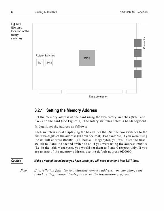
Figure 1ISA card: location of the rotary switches
3.2.1 Setting the Memory AddressSet the memory address of the card using the two rotary switches (SW1 and SW2) on the card (see Figure 1). The rotary switches select a 64Kb segment.
In detail, set the address as follows:
Each switch is a dial displaying the hex values 0-F. Set the two switches to the first two digits of the address (in hexadecimal). For example, if you were using the default address 0D0000 (i.e. below 1 megabyte), you would set the first switch to 0 and the second switch to D. If you were using the address F00000 (i.e. in the 16th Megabyte), you would set them to F and 0 respectively. If you are unsure of the memory address, use the default address 0D0000.
Caution Make a note of the address you have used: you will need to enter it into SMIT later.
Note If installation fails due to a clashing memory address, you can change the switch settings without having to re-run the installation program.

RIO for IBM AIX User’s Guide Installing the Host Card 9
3.2.2 Installing the ISA Host CardThe ISA host card fits inside your machine by slotting into one of the ISA slots on the motherboard.
1. Make sure that your system is switched off.
2. Remove the cover of the machine, locate an empty ISA slot and insert the card.
3. Repeat for each host card you want to install.
4. Replace the cover of your computer, and reboot.
3.2.3 Configuring the ISA Host Card1. Run SMIT. Select ‘Devices', then select ‘ISA Adapters' then select ‘Add an
ISA Adapter'.
2. Choose ‘ISA Bus’ for the parent device; then select the RIO Host Adapter. In the field ‘Bus Memory Address' enter the same address you set on the rotary switches.
Note Do not specify ‘0x' before the hexadecimal address value.
3. In the ‘Bus Interrupt Field' enter an interrupt level of your choosing. Other devices installed in your machine may occupy some of the interrupt levels offered in this field.
When installing a second card, choose both a unique memory address and interrupt level. Ensure that either both cards use ‘polled' mode or both cards use numbered interrupt levels. Do not mix polled and numbered interrupt levels.
You should see in ‘Output': ‘RIO0 available'; in this example, ‘0' is the first RIO host card installed. If you have an error you may have entered an incorrect/clashing address. For help, see the “Troubleshooting” section in Appendix B.
4. Now go to Chapter 4.
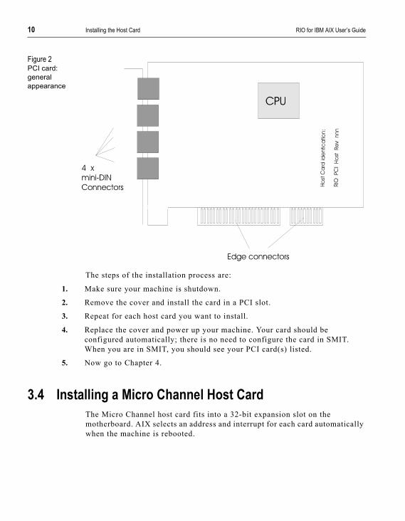
3.3 Installing a PCI Host CardThe RIO PCI Host Card is configured automatically by the machine into which it is installed. The layout of the card is shown in Figure 2; you insert the card solder side up.
10 Installing the Host Card RIO for IBM AIX User’s Guide
Figure 2PCI card: general appearance
The steps of the installation process are:
1. Make sure your machine is shutdown.
2. Remove the cover and install the card in a PCI slot.
3. Repeat for each host card you want to install.
4. Replace the cover and power up your machine. Your card should be configured automatically; there is no need to configure the card in SMIT. When you are in SMIT, you should see your PCI card(s) listed.
5. Now go to Chapter 4.
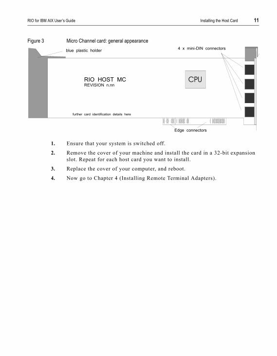
3.4 Installing a Micro Channel Host CardThe Micro Channel host card fits into a 32-bit expansion slot on the motherboard. AIX selects an address and interrupt for each card automatically when the machine is rebooted.
RIO for IBM AIX User’s Guide Installing the Host Card 11
Figure 3 Micro Channel card: general appearance
1. Ensure that your system is switched off.
2. Remove the cover of your machine and install the card in a 32-bit expansion slot. Repeat for each host card you want to install.
3. Replace the cover of your computer, and reboot.
4. Now go to Chapter 4 (Installing Remote Terminal Adapters).
CPU
blue plastic holder 4 x mini-DIN connectors
Edge connectors
RIO HOST MCREVISION n.nn
further card identification details here

12 Installing the Host Card RIO for IBM AIX User’s Guide

RIO for IBM AIX User’s Guide Installing Remote Terminal Adapters 13
C h a p t e r 4
Installing Remote Terminal Adapters
Installation Tips
Getting to Know Your RTAs
Installing an 8-Port RTA
Installing a 16-port RTA
Installing a RIO Fibre Optic Link Kit
Installing the RIO Long Distance Module
4.1 Installation TipsRemote Terminal Adapters (RTAs) are the external adapters that connect to the RIO Host Card and provide the serial ports for your system. RTAs are available as 8 or 16 port models, and with a wide range of port/connector types (see Appendix A).
The host card has four RIO Link ports, each of which can be connected directly to an RTA. Each RTA also has four RIO Link ports, enabling you to connect RTAs to other RTAs rather than directly to the host card. This gives you the flexibility to configure your RIO system how you want to.
You can add a maximum of 128 ports to a host card using any combination of units.
RIO provides four cabling options: standard RIO twisted-pair cabling (up to 75m), extended twisted-pair cabling (up to 1Km), fibre optic cabling (up to 1Km), and leased line/modem connection. Each host card and RTA model will support all four types of connection.
14 Installing Remote Terminal Adapters RIO for IBM AIX User’s Guide
RIO’s unique architecture enables you to add RTAs while the system is up-and-running. Configuration status messages will appear on the system console as RTAs are added.
The link cables supplied with RIO are 5 metres long. Using the specifications for link cables in Appendix A (Port Specifications & Cabling) you can build your own cables up to 75 metres long.
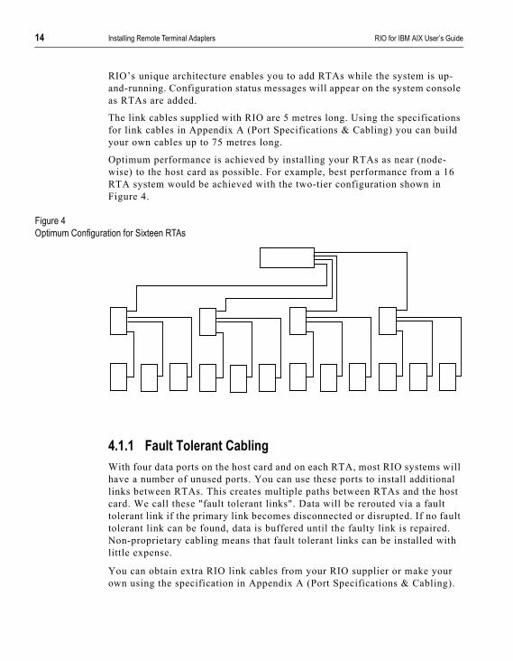
Optimum performance is achieved by installing your RTAs as near (node-wise) to the host card as possible. For example, best performance from a 16 RTA system would be achieved with the two-tier configuration shown in Figure 4.
Figure 4Optimum Configuration for Sixteen RTAs
4.1.1 Fault Tolerant CablingWith four data ports on the host card and on each RTA, most RIO systems will have a number of unused ports. You can use these ports to install additional links between RTAs. This creates multiple paths between RTAs and the host card. We call these "fault tolerant links". Data will be rerouted via a fault tolerant link if the primary link becomes disconnected or disrupted. If no fault tolerant link can be found, data is buffered until the faulty link is repaired. Non-proprietary cabling means that fault tolerant links can be installed with little expense.
You can obtain extra RIO link cables from your RIO supplier or make your own using the specification in Appendix A (Port Specifications & Cabling).
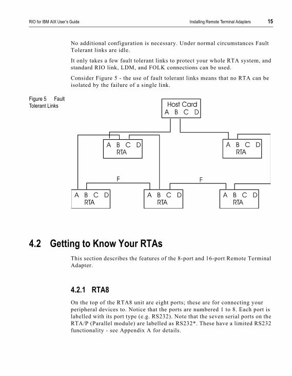
RIO for IBM AIX User’s Guide Installing Remote Terminal Adapters 15
No additional configuration is necessary. Under normal circumstances Fault Tolerant links are idle.
It only takes a few fault tolerant links to protect your whole RTA system, and standard RIO link, LDM, and FOLK connections can be used.
Consider Figure 5 - the use of fault tolerant links means that no RTA can be isolated by the failure of a single link.
Figure 5 Fault Tolerant Links
4.2 Getting to Know Your RTAsThis section describes the features of the 8-port and 16-port Remote Terminal Adapter.
4.2.1 RTA8On the top of the RTA8 unit are eight ports; these are for connecting your peripheral devices to. Notice that the ports are numbered 1 to 8. Each port is labelled with its port type (e.g. RS232). Note that the seven serial ports on the RTA/P (Parallel module) are labelled as RS232*. These have a limited RS232 functionality - see Appendix A for details.

16 Installing Remote Terminal Adapters RIO for IBM AIX User’s Guide
On the side of the unit are four RIO Link sockets and the power supply socket. The power supply socket is for the external power supply unit (PSU) supplied with the RTA. Notice that the Link sockets are labelled A to D. RIO uses these letters to address RTAs in your network. They are also used in the RTA Topology (See Section Section 7.1 Draw RIO RTA Topology).
Each RTA has six diagnostic LEDs which enable you to judge the status of the RTA at a glance.
Each RIO link has an LED, the colour of which identifies the status of the link:
• Orange - the link is transmitting system traffic (e.g. boot packets).
• Green - the link is transmitting data traffic.
• Red (flashing) - errors are being detected on the link.
• Red (for about 20 seconds then off) - the link has failed or has been disconnected.
A full description of link LED states is given, in context, in Section 4.3 Installing an 8-Port RTA.
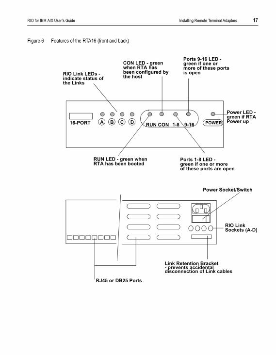
4.2.2 RTA16The 16-port RTA is a rackable, stackable unit, ideal for locating ports close to the host server — for use with a patch panel for example. Alternatively, the 16-port can be used just like an 8-port RTA and located within your workgroups.The RTA16 is fully compatible with all 8-port RTA models, and will support up to 2 LDM or 4 FOLK connections.
Available with DB25 or RJ45 ports, the RTA16 also features an integral power supply unit, nine diagnostic LEDs, and a lockable bracket which will prevent accidental disconnection of RIO Link cables. The main features of the unit are highlighted in Figure 6 below.
Caution do not stack more than four RTA16s on top of one another
RIO for IBM AIX User’s Guide Installing Remote Terminal Adapters 17
Figure 6 Features of the RTA16 (front and back)
POWERRUN CON 9-161-8A B C D16-PORT
RIO Link LEDs -indicate status ofthe Links
CON LED - greenwhen RTA hasbeen configured bythe host
Ports 9-16 LED -green if one ormore of these portsis open
Ports 1-8 LED -green if one or moreof these ports are open
RUN LED - green whenRTA has been booted
Power LED -green if RTAPower up
RJ45 or DB25 Ports
Power Socket/Switch
Link Retention Bracket- prevents accidentaldisconnection of Link cables
RIO Link Sockets (A-D)
18 Installing Remote Terminal Adapters RIO for IBM AIX User’s Guide
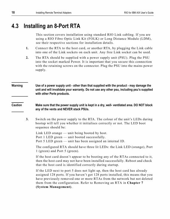
4.3 Installing an 8-Port RTAThis section covers installation using standard RIO Link cabling. If you are using a RIO Fibre Optic Link Kit (FOLK) or Long Distance Module (LDM), see their respective sections for installation details.
1. Connect the RTA to the host card, or another RTA, by plugging the Link cable into one of the Link sockets on each unit. Any free Link socket can be used.
2. The RTA should be supplied with a power supply unit (PSU). Plug the PSU into the socket marked Power. It is important that you secure this connection with the retaining screws on the connector. Plug the PSU into the mains power supply.
Warning Use of a power supply unit - other than that supplied with the product - may damage the unit and will invalidate your warranty. Do not use any other psu, including psu’s supplied with other Perle products.
Caution Make sure that the power supply unit is kept in a dry, well- ventilated area. DO NOT block any of the vents and NEVER stack PSUs.
3. Switch on the power supply to the RTA. The colour of the unit’s LEDs during bootup will tell you whether it initialises correctly or not. The LED boot sequence should be:
Link LED orange — unit being booted by host.Port 1 LED green — unit booted successfully.Port 5 LED green — unit has been assigned an internal ID.
The configured RTA should have three lit LEDs: the Link LED (orange), Port 1 (green) and Port 5 (green).
If the host card doesn’t appear to be booting any of the RTAs connected to it, then the host card may not have been installed successfully. Reboot and check that the host card is identified correctly during startup.
If the LED next to port 5 does not light up, then the host card has already assigned 128 ports. If you haven’t got 128 ports installed, this means that you have previously removed one or more RTAs from the network but not deleted them from the configuration. Refer to Removing an RTA in Chapter 7 (System Management).
RIO for IBM AIX User’s Guide Installing Remote Terminal Adapters 19
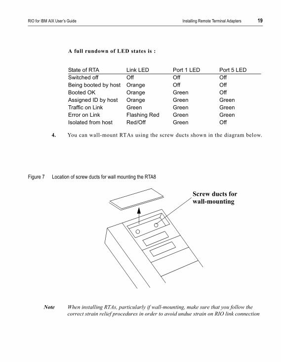
A full rundown of LED states is :
4. You can wall-mount RTAs using the screw ducts shown in the diagram below.
Figure 7 Location of screw ducts for wall mounting the RTA8
Note When installing RTAs, particularly if wall-mounting, make sure that you follow the correct strain relief procedures in order to avoid undue strain on RIO link connection
State of RTA Link LED Port 1 LED Port 5 LEDSwitched off Off Off OffBeing booted by host Orange Off OffBooted OK Orange Green OffAssigned ID by host Orange Green GreenTraffic on Link Green Green GreenError on Link Flashing Red Green GreenIsolated from host Red/Off Green Off
Screw ducts for wall-mounting

20 Installing Remote Terminal Adapters RIO for IBM AIX User’s Guide
4.4 Installing a 16-port RTAThis section covers installation using standard RIO Link cabling. If you are using a RIO Fibre Optic Link Kit (FOLK) or Long Distance Module (LDM), see their respective sections for installation details.
1. Connect the RTA to the host card (or another RTA) by plugging the RIO cable into a link socket on each unit.
If you are going to stack (no more than four high) or rack the RTA16, use the short RIO cable supplied with the unit. If you need a longer cable, contact your supplier or refer to the RIO Link cable specification in Appendix A (Port Specifications & Cabling).
The RTA16 has an integral power supply. Take the power cable supplied with the RTA and plug it into the socket marked ‘Power’ in the back of the unit. Plug the other end of the cable into the AC (mains) power supply. Switch on the RTA power supply.
2. Switch on the AC power supply. The colour of the unit’s LEDs during bootup will tell you whether it initialises correctly or not. The LED boot sequence should be:
The RUN and CON LEDs will remain green. The colour of the Link LED depends on the state of the Link. A full run-down of LED states is given below:
WARNING If the CON LED does not light up, then you have already installed the maximum number of RTAs (up to 128 ports) on this host card. This situation may arise if you have previously removed RTAs from the system but not deleted them. See ‘Removing an RTA’ in Chapter 7 System Management.
Link LED: orange (unit being booted by host)RUN LED: green (unit booted successfully)CON LED: green (a software connection has been made
between the RTA and the RIO driver)
State of RTA Link LED RUN LED CON LEDSwitched off Off Off OffBeing booted by Host Orange Off OffBooted OK Orange Green OffAssigned ID by Host Orange Green GreenTraffic on Link Green Green GreenError on Link Flashing Red Green GreenIsolated from Host Red/ for 20
seconds then Off
Green Off

RIO for IBM AIX User’s Guide Installing Remote Terminal Adapters 21
4.5 Installing a RIO Fibre Optic Link KitThe RIO Fibre-optic Link Kit (FOLK) enables you to extend the range of a RIO Link, via fibre-optic cable, to one kilometre. The Kit consists of two fibre-optic modules (see Figure 8). The module consists of a one-metre RIO Link cable connected to a fibre-optic converter. This converts the transputer signals into light. The fibre-optic cable plugs into these converters, one at each end of the connection.
Figure 8Fibre Optic Module
4.5.1 To install the FOLK1. The fibre-optic cable should already be installed. It will probably have been
wired into a junction box, and should emerge in the form of a patch lead with two bayonet connectors at the end.
Fibre-optic Patch lead
Transmit LED - This flashes yellow to indicate transmission
Power LED - This lights green when the fibre-optic connection live at both ends
Link Cable
Receive LED - This flashes orange to
(output).
indicate data input

22 Installing Remote Terminal Adapters RIO for IBM AIX User’s Guide
2. At one end of the fibre-optic cable, plug the patch lead into the transceivers of the fibre-optic converter. Keep the caps of the transceivers safe. These should be replaced if the patch lead is removed (because any dust or dirt will impede the passage of light, thus corrupting the signal).
3. Plug the RIO Link cable into one of the Link sockets on the side of the RTA/Host Card to be connected.
4. Repeat at the other end of the fibre-optic cable. Make sure that each strand of the fibre-optic cable is plugged into a transmit channel at one end and a receive channel at the other.
5. When the units (Host card/RTA) at each end are powered up, check that the Connect LED on each fibre-optic module is green.
Note You will notice that on each side of the fibre-optic module is a dovetail connector. These enable adjacent modules to be connected together .
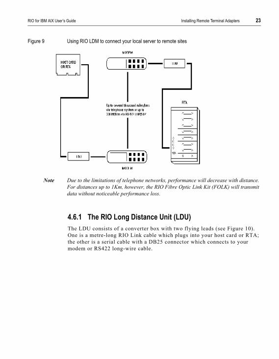
4.6 Installing the RIO Long Distance ModuleThe RIO Long Distance Module (LDM) enables you to extend your RIO system in two ways:
• via leased line or standard telephone connection. Connections can be made over thousands of miles using synchronous (X.21/X.21bis) or asynchronous interfaces.
• via twisted-pair RS422 “Long-wire” cable up to 1Km. This may provide a more cost-effective solution than the RIO Fibre Optic Link Kit in environments with low interference levels or a low security risk.
Note The LDM is specifically designed for use on high-speed synchronous connections. Slower, asynchronous speeds are supported but are only recommended for applications where low throughput is acceptable.
You can increase the number of RTAs on the remote site using standard RIO cables, making the LDM more cost-effective and more practical than a multiplexor.
The LDM consists of two Long Distance Units (LDUs). One LDU connects your local host card or RTA to a modem, the other connects the remote RTA to a modem (see Figure 9). The speed and protocol are configured using a dial on the LDU.
RIO for IBM AIX User’s Guide Installing Remote Terminal Adapters 23
Figure 9 Using RIO LDM to connect your local server to remote sites
Note Due to the limitations of telephone networks, performance will decrease with distance. For distances up to 1Km, however, the RIO Fibre Optic Link Kit (FOLK) will transmit data without noticeable performance loss.
4.6.1 The RIO Long Distance Unit (LDU)The LDU consists of a converter box with two flying leads (see Figure 10). One is a metre-long RIO Link cable which plugs into your host card or RTA; the other is a serial cable with a DB25 connector which connects to your modem or RS422 long-wire cable.

24 Installing Remote Terminal Adapters RIO for IBM AIX User’s Guide
Figure 10 RIO Long Distance Unit
4.6.2 Installing an LDM Connection1. For modem installations, a converter cable must be used to connect the LDU
DB25 flying lead to the modem. On long-wire installations, the long-wire can be connected directly to the DB25 flying lead. Make sure your long-wire or modem cable conforms to the specifications defined in Appendix A (Port Specifications & Cabling).
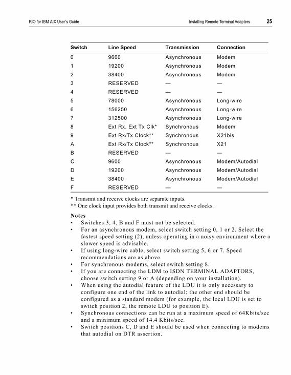
2. Using a small screwdriver, set the rotary switch on each LDU to the required setting:
DB25 flying lead: Connects to
Data Flow LED - Flashes green to indicate incoming data
Power LED - Turns greenwhen the unit is connectionto the host card or RTA
RIO Link flying lead:
Error LED - Flashes red when an error
Rotary Switch:
connects to host card or RTA
Long-wire or modem cable
has been detectedon the Link
12 protocol/speedsettings
Dovetail connector: enables adjacent units to be clipped together
RIO for IBM AIX User’s Guide Installing Remote Terminal Adapters 25
* Transmit and receive clocks are separate inputs.** One clock input provides both transmit and receive clocks.
Notes• Switches 3, 4, B and F must not be selected.• For an asynchronous modem, select switch setting 0, 1 or 2. Select the
fastest speed setting (2), unless operating in a noisy environment where a slower speed is advisable.
• If using long-wire cable, select switch setting 5, 6 or 7. Speed recommendations are as above.
• For synchronous modems, select switch setting 8.• If you are connecting the LDM to ISDN TERMINAL ADAPTORS,
choose switch setting 9 or A (depending on your installation).• When using the autodial feature of the LDU it is only necessary to
configure one end of the link to autodial; the other end should be configured as a standard modem (for example, the local LDU is set to switch position 2, the remote LDU to position E).
• Synchronous connections can be run at a maximum speed of 64Kbits/sec and a minimum speed of 14.4 Kbits/sec.
• Switch positions C, D and E should be used when connecting to modems that autodial on DTR assertion.
Switch Line Speed Transmission Connection
0 9600 Asynchronous Modem1 19200 Asynchronous Modem2 38400 Asynchronous Modem3 RESERVED — —4 RESERVED — —5 78000 Asynchronous Long-wire6 156250 Asynchronous Long-wire7 312500 Asynchronous Long-wire8 Ext Rx, Ext Tx Clk* Synchronous Modem9 Ext Rx/Tx Clock** Synchronous X21bisA Ext Rx/Tx Clock** Synchronous X21B RESERVED — —C 9600 Asynchronous Modem/AutodialD 19200 Asynchronous Modem/AutodialE 38400 Asynchronous Modem/AutodialF RESERVED — —
26 Installing Remote Terminal Adapters RIO for IBM AIX User’s Guide
3. Make sure your modems are configured correctly. For synchronous modes:
• Speeds below 14.4 Kbit/s are not supported.• Modems should be configured to 8 data bits. • Flow control must be disabled.• Command echo must be disabled.• Display of result codes must be suppressed.
For asynchronous modes:
• Modems must support a minimum of V32bis.• Modems must connect at a minimum speed of 9600 baud.• Modems should be set to 8 data bits, 1 stop bit and no parity. • Hardware flow control must be enabled.• Command echo must be disabled.• Display of result codes must be suppressed.
4. If using modems, take one of the LDUs and connect the DB25 flying lead to the modem converter cable. Connect the modem converter cable to the modem. Make sure that the modem is powered on before connecting the LDU to your RIO system
5. If using a long-wire connection, take one of the LDUs and connect the DB25 flying lead to your long-wire cable.
6. Connect the RIO Link flying lead to any free Link socket on the Host Card/RTA to be connected.
7. Repeat for the LDU at the other end of the connection.8. When the units (Host Card/RTAs) at each end of the LDM connection are
powered up, check that the Power LED on each LDU is green.
Note Once a connection has been established, some asynchronous modems are able to negotiate a faster line speed on the telecommunications link. If you are using such modems, your RTAs will temporarily disconnect and then reconnect at the higher speed. This is, of course, to your advantage, and the fault status messages output to the console by the RIO configuration software can be ignored.
Note Terminals logged in when modems are disconnected or the line dropped will continue where they left off when the line is reconnected.

RIO for IBM AIX User’s Guide Configuring RTAs 27
C h a p t e r 5
Configuring RTAs
Defining an RTA
Enabling a Login Device
Enabling a Print Device
5.1 Defining an RTA1. Enter smit rio at the command line to display the “Specialix RIO” menu.
(alternatively, start smit, and then select Devices, Communication, Specialix RIO).
2. From this menu select ‘Remote Terminal Adapter', then ‘Add a Specialix RIO RTA'. All undefined RTAs connected to your host card will be listed:
The RTAs are listed by their ID numbers, detected by AIX.
Remote Terminal Adapter ID
Select one item from the liste000106ee1000013e000000de1000024
F1 = Help F2 = Help F3 = CancelF8 = Image F10 = Exit Enter = Do
28 Configuring RTAs RIO for IBM AIX User’s Guide
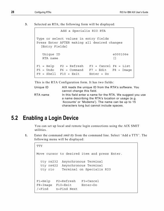
3. Selected an RTA; the following form will be displayed:
This is the RTA Configuration form. It has two fields:
5.2 Enabling a Login DeviceYou can set up local and remote login connections using the AIX SMIT utilities.
1. Enter the command smit tty from the command line. Select ‘Add a TTY’. The following menu will be displayed:
Add a Specialix RIO RTA
Type or select values in entry fieldsPress Enter AFTER making all desired changes
[Entry Fields]
Unique ID e000106eRTA name []
F1 = Help F2 = Refresh F3 = Cancel F4 = ListF5 = Undo F6 = Command F7 = Edit F8 = ImageF9 = Shell F10 = Exit Enter = Do
Unique ID AIX reads the unique ID from the RTA's software. You cannot change this field.
RTA name In this field enter a name for the RTA. We suggest you use a name describing the RTA's location or usage (e.g. ‘Accounts' or ‘Modems'). The name can be up to 15 characters long but cannot include spaces.
TTY
Move cursor to desired item and press Enter.
tty rs232 Asynchronous Terminaltty rs422 Asynchronous Terminaltty rio Terminal on Specialix RIO
F1=Help F2=Refresh F3=CancelF8=Image F10=Exit Enter=Do/=Find n=Find Next
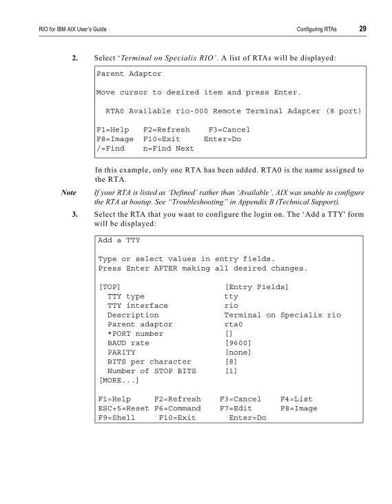
RIO for IBM AIX User’s Guide Configuring RTAs 29
2. Select ‘Terminal on Specialix RIO’. A list of RTAs will be displayed:
In this example, only one RTA has been added. RTA0 is the name assigned to the RTA.
Note If your RTA is listed as ‘Defined’ rather than ‘Available’, AIX was unable to configure the RTA at bootup. See “Troubleshooting” in Appendix B (Technical Support).
3. Select the RTA that you want to configure the login on. The ‘Add a TTY' form will be displayed:
Parent Adaptor
Move cursor to desired item and press Enter.
RTA0 Available rio-000 Remote Terminal Adapter (8 port)
F1=Help F2=Refresh F3=CancelF8=Image F10=Exit Enter=Do/=Find n=Find Next
Add a TTY
Type or select values in entry fields.Press Enter AFTER making all desired changes.
[TOP] [Entry Fields]TTY type ttyTTY interface rioDescription Terminal on Specialix rioParent adaptor rta0*PORT number []BAUD rate [9600]PARITY [none]BITS per character [8]Number of STOP BITS [1]
[MORE...]
F1=Help F2=Refresh F3=Cancel F4=ListESC+5=Reset F6=Command F7=Edit F8=ImageF9=Shell F10=Exit Enter=Do

30 Configuring RTAs RIO for IBM AIX User’s Guide
4. Complete the fields as described below:
Note The speed 50 is mapped to 57600 baud. The speed 110 is mapped to 115200 baud. So, to select 57600 baud on a Specialix port, for example, you should select 50 baud in the ‘BAUD rate’ field. This mapping can be disabled in the ‘Change/Show Host Card’ option
Port number The host card recognizes whether 8 or 16 port RTAs are connected, and names the unit’s ports 0-7 or 0-15.
BAUD rate You are presented with the following baud rates: 50, 75, 110, 134,150, 200, 300, 600, 1200, 1800, 2400, 4800, 9600, 19200 and 38400.Recommended Value: 9600
PARITY Recommended Value: no parity
BITS per character
Recommended Value: 8
Number of STOP BITS
Certain applications and system functions are tailored to specific terminal types. Terminals do not identify themselves to the system so this field can be used to set the TERM environment variable. This field also controls transparent print on and off strings.
Terminal Type Certain applications and system functions are tailored to specific terminal types.Terminals do not identify themselves to the system so this field can be used to set the TERM environment variable. This field also controls transparent on and off strings.
Status of device at BOOT time
Make sure this field is set to available.
Enable Login This attribute indicates the type of login connection required. The available values are:
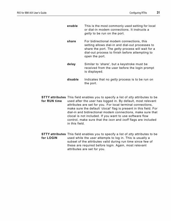
RIO for IBM AIX User’s Guide Configuring RTAs 31
enable This is the most commonly used setting for local or dial-in modem connections. It instructs a getty to be run on the port.
share For bidirectional modem connections, this setting allows dial-in and dial-out processes to share the port. The getty process will wait for a dial-out process to finish before attempting to open the port.
delay Similar to ‘share', but a keystroke must be received from the user before the login prompt is displayed.
disable Indicates that no getty process is to be run on the port.
STTY attributes for RUN time
This field enables you to specify a list of stty attributes to be used after the user has logged in. By default, most relevant attributes are set for you. For local terminal connections, make sure the default ‘clocal' flag is present in this field. For dial-in and bidirectional modem connections, make sure that clocal is not included. If you want to use software flow control, make sure that the ixon and ixoff flags are included in this field.
STTY attributes for LOGIN
This field enables you to specify a list of stty attributes to be used while the user attempts to log in. This is usually a subset of the attributes valid during run time since few of these are required before login. Again, most relevant attributes are set for you.

32 Configuring RTAs RIO for IBM AIX User’s Guide
5. When you have completed the form, press Enter to add the TTY to the database. A command status report will be displayed:
AIX will assign the lowest unassigned tty number to the port. For this reason, we recommend that you configure your RTAs in order.
Note If the message ‘Command: failed' is displayed, the tty has not been added to the database. Some kind of error message will be displayed by SMIT. The most likely cause is that you haven't completed the form correctly. Press F3 to return to the form.
Note Ports may be reconfigured or removed but they must not be in use at the time. Therefore, if a port is in use, disable login on a port via the ‘Change/Show Characteristics of a TTY’ option on the SMIT TTY menu. Use the same option for reconfiguring a port. For removing a port use the ‘Remove a TTY’ option.
COMMAND STATUS
Command: OK stdout: yes stderr: no
Before command completion, additional instructions mayappear below.
tty1 Available
F1=Help F2=Refresh F3=Cancel F6=CommandF8=Image F9=Shell F10=Exit

RIO for IBM AIX User’s Guide Configuring RTAs 33
5.3 Enabling a Print DeviceThis section describes how to add a printer and a print queue. RIO will support both direct serial and parallel printing (printer attached to RTA serial port) or transparent printing (printer attached to terminal).
Note You must have login enabled on a port before using transparent printing. See Section 5.1 (Enabling a Login Device).
5.3.1 Adding a Printer1. Use the FastPath command smit pdp to display the Printer/Plotter Devices
menu. Select ‘Add a Printer/Plotter'. A list of printer/plotter devices will be displayed:
2. Select the model of printer you are going to attach. You will next be asked to select the appropriate printer interface:
Printer/Plotter Type
Move cursor to desired item and press Enter.
[TOP]2380 IBM 2380 Personal Printer II2381 IBM 2381 Personal Printer II2390 IBM 2390 Personal Printer II2391 IBM 2391 Personal Printer II3812-2 IBM 3812 Model 2 Page Printer3816 IBM 3816 Page Printer4019 IBM 4019 LaserPrinter4019 IBM 4019 LaserPrinter4029 IBM 4029 LaserPrinter4039 IBM 4039 LaserPrinter4070 IBM 4070 IJ printer
[MORE...]
F1=Help F2=Refresh F3=CancelF8=Image F10=Exit Enter=Do/=Find n=Find Next

34 Configuring RTAs RIO for IBM AIX User’s Guide
3. Select rio for direct printing or rio_xp for transparent printing (printer attached to the rear of a terminal). If you select the direct printing device, you will next be asked to select which RTA the printer is attached to. If you selct the transparent print device, you will be askedto select which terminal the printer is attached to. When you have selected, the printer configuration form will be displayed:
Printer/Plotter Interface
Move cursor to desired item and press Enter
parallelrs232rs422rio_xprio
F1=Help F2=Refresh F3=CancelF8=Image F10=Exit Enter=Do/=Find n=Find Next
Add a Printer/Plotter
Type or select values in entry fields.Press Enter AFTER making all desired changes.
[TOP] [Entry Fields]Printer/Plotter type 2380Printer/Plotter interface rio (or rio_xp)Description IBM2380Personal
print>Parent adaptor rta0*PORT number [] +BAUD rate [9600] +PARITY [none] +
[MORE...]
F1=Help F2=Refresh F3=Cancel F4=ListF5=Undo F6=Command F7=Edit F8=ImageF9=Shell F10=Exit Enter=Do
RIO for IBM AIX User’s Guide Configuring RTAs 35
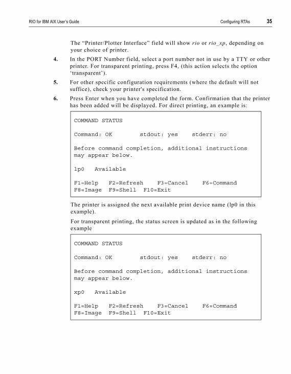
The “Printer/Plotter Interface” field will show rio or rio_xp, depending on your choice of printer.
4. In the PORT Number field, select a port number not in use by a TTY or other printer. For transparent printing, press F4, (this action selects the option ‘transparent’).
5. For other specific configuration requirements (where the default will not suffice), check your printer's specification.
6. Press Enter when you have completed the form. Confirmation that the printer has been added will be displayed. For direct printing, an example is:
The printer is assigned the next available print device name (lp0 in this example).
For transparent printing, the status screen is updated as in the following example
COMMAND STATUS
Command: OK stdout: yes stderr: no
Before command completion, additional instructionsmay appear below.
lp0 Available
F1=Help F2=Refresh F3=Cancel F6=CommandF8=Image F9=Shell F10=Exit
COMMAND STATUS
Command: OK stdout: yes stderr: no
Before command completion, additional instructionsmay appear below.
xp0 Available
F1=Help F2=Refresh F3=Cancel F6=CommandF8=Image F9=Shell F10=Exit
36 Configuring RTAs RIO for IBM AIX User’s Guide
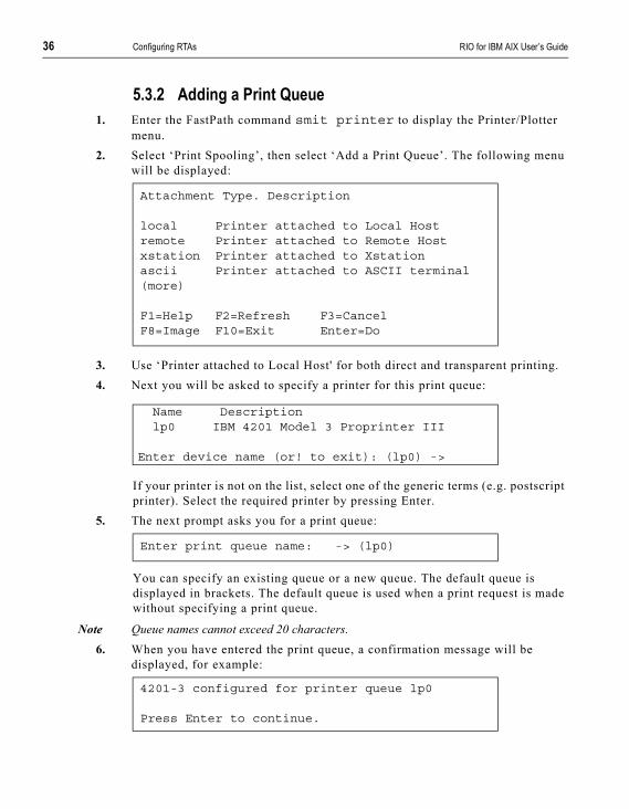
5.3.2 Adding a Print Queue1. Enter the FastPath command smit printer to display the Printer/Plotter
menu.2. Select ‘Print Spooling’, then select ‘Add a Print Queue’. The following menu
will be displayed:
3. Use ‘Printer attached to Local Host' for both direct and transparent printing.4. Next you will be asked to specify a printer for this print queue:
If your printer is not on the list, select one of the generic terms (e.g. postscript printer). Select the required printer by pressing Enter.
5. The next prompt asks you for a print queue:
You can specify an existing queue or a new queue. The default queue is displayed in brackets. The default queue is used when a print request is made without specifying a print queue.
Note Queue names cannot exceed 20 characters.6. When you have entered the print queue, a confirmation message will be
displayed, for example:
Attachment Type. Description
local Printer attached to Local Hostremote Printer attached to Remote Hostxstation Printer attached to Xstationascii Printer attached to ASCII terminal(more)
F1=Help F2=Refresh F3=CancelF8=Image F10=Exit Enter=Do
Name Descriptionlp0 IBM 4201 Model 3 Proprinter III
Enter device name (or! to exit): (lp0) ->
Enter print queue name: -> (lp0)
4201-3 configured for printer queue lp0
Press Enter to continue.

RIO for IBM AIX User’s Guide Configuring RTAs 37
The printer queue is now available for use with the AIX enq, qprt, lpr and lp commands.
5.3.3 Reconfiguring a Print QueueFrom the ‘Devices' menu, select ‘Printer/Plotter', followed by ‘Print Spooling', followed by one of the following:
‘Add a Print Queue'
‘Change/Show Print Queue Characteristics'
‘Remove a Print Queue'
For more information on the other options shown on this screen, refer to your AIX documentation; (the options are not related to the RIO software).

38 Configuring RTAs RIO for IBM AIX User’s Guide

RIO for IBM AIX User’s Guide RIO Dual Host Failsafe 39
C h a p t e r 6
RIO Dual Host Failsafe
What is RIO Dual Host Failsafe?
Installing a Master/Slave Dual Host System
Installing a Shared Dual Host Failsafe System
6.1 What is RIO Dual Host Failsafe?RIO enables you to protect against server failure by connecting your RTA subsystem to two host cards, installed in separate machines. If one host fails, the other takes control of the RTAs.
In the form described in this manual, RIO Dual Host Failsafe provides support where the switch to the reserve host is initiated manually. RIO does not provide automatic host-switching, but it does provide the support for such a system if installed.
Recommendations for an advanced dual host failsafe system are two servers sharing a RAID disk array and watchdog software, which you can obtain from a third party. Using these products you will need to set up background processes to ensure that RIO’s RTA and port information is kept up-to-date on the reserve host.
Note In a Dual Host Failsafe configuration, only one RIO Host Card can be installed in each server.
The relationship between the two hosts in a Dual Host Failsafe system may take two forms: Master/Slave or Shared.
40 RIO Dual Host Failsafe RIO for IBM AIX User’s Guide
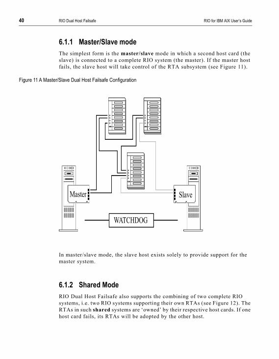
6.1.1 Master/Slave modeThe simplest form is the master/slave mode in which a second host card (the slave) is connected to a complete RIO system (the master). If the master host fails, the slave host will take control of the RTA subsystem (see Figure 11).
Figure 11 A Master/Slave Dual Host Failsafe Configuration
In master/slave mode, the slave host exists solely to provide support for the master system.
6.1.2 Shared ModeRIO Dual Host Failsafe also supports the combining of two complete RIO systems, i.e. two RIO systems supporting their own RTAs (see Figure 12). The RTAs in such shared systems are ‘owned’ by their respective host cards. If one host card fails, its RTAs will be adopted by the other host.
WATCHDOG
SlaveMaster

RIO for IBM AIX User’s Guide RIO Dual Host Failsafe 41
Figure 12 A Shared Dual Host Failsafe Configuration
6.2 Installing a Master/Slave Dual Host SystemThe steps required to configure a master/slave dual host failsafe system are outlined in Figure 13 and listed here:
WATCHDOG

42 RIO Dual Host Failsafe RIO for IBM AIX User’s Guide
Figure 13 The four main steps to installing a Master/Slave Dual Host Failsafe system
1. Install and configure your main (master) RIO system.2. Using the “Save RIO Device Configuration” option on the smit RIO menu
(see Section 7.15 Save RIO Device Configuration), save the configuration of your master RIO system to file.
3. Install a RIO host card and device driver in the slave machine, but do not connect the slave host to the RTA subsystem yet.
4. Disconnect physically the RTA sub-system from the master host card and connect it to the slave card.
5. Copy the directory /usr/tmp/riocnf and its contents from the master system to the slave system. This is where the RIO configuration information is saved. Now load the configuration information using the “Load RIO Device Configuration” option on the smit RIO menu (see Section 7.16 Load RIO Device Configuration).
1. Install your mainRIO system. Thissystem will be calledthe `Master` system.
4. Leaving the RTAsub-systemconnected to theslave host, makeextra connectionsback to the Masterhost. These links arecalled `HostInterconnections`.
2. Install aRIO hostcard inanothermachine.Thismachine willbe called theslave host.
3.Disconnect the RTA sub-system fromthe master host card and connect it to theslave card.
5. Re-boot both machine and power-cycle the RTAs
SlaveMaster

RIO for IBM AIX User’s Guide RIO Dual Host Failsafe 43
6. On the slave card, in SMIT, use the option ‘Change/Show Characteristics of a Specialix RIO Host Adapter’ to set the slave card to ‘slave’.
7. Leaving the RTA sub-system connected to the slave host card, use standard RIO cabling to make extra connections back to the master host card. Ensure that all RTAs have at least one route to the master host, and that all RTAs are protected by fault tolerant links. You can use as many of the master host’s links as you need.
8. Re-boot both machines simultaneously. At the same time power-cycle the RTAs. (The exact order of all these actions is not important, provided you do them all at approximately the same time).
Your Dual Host Failsafe system should now be set-up
6.2.1 When the Master Host FailsIf your master host fails, use the instructions below to switch control of the RTA subsystem to the slave host. If you want to automate the process you will need to install watchdog software to monitor both servers, and run the appropriate commands on the slave host when required.
1. Go to the slave host and in the option ‘Change/Show Characteristics of a Specialix RIO Host Adapter’, change the host card from ‘slave’ to ‘master’.
2. Reboot interconnected RTAs using the “Reboot RTAs” feature on the Remote Terminal Adapters menu (see Section 7.9 Reboot RTAs).
3. The original slave host card, now configured as ‘master’, should be able to run your RTA system, while you attend to the failed host.
4. While repairing the failed master host, when you power it up and down, the RTAs will remain under the control of the working host (now acting as the master).
6.2.2 When the failed host is available again:Assuming you want the failed master to resume control of the RTAs, do the following:
1. Ensure the repaired machine is turned off.2. On the working machine, in the option ‘Change/Show a Specialix RIO Host
Adapter’, change the host card from ‘master’ back to ‘slave’.3. Leave all the physical connections between RTAs and the two host cards in
place.4. Turn on the repaired master host machine.
44 RIO Dual Host Failsafe RIO for IBM AIX User’s Guide
5. On the master, reboot interconnected RTAs using the “Reboot RTAs” feature on the Remote Terminal Adapters menu (see Section 7.9 Reboot RTAs).
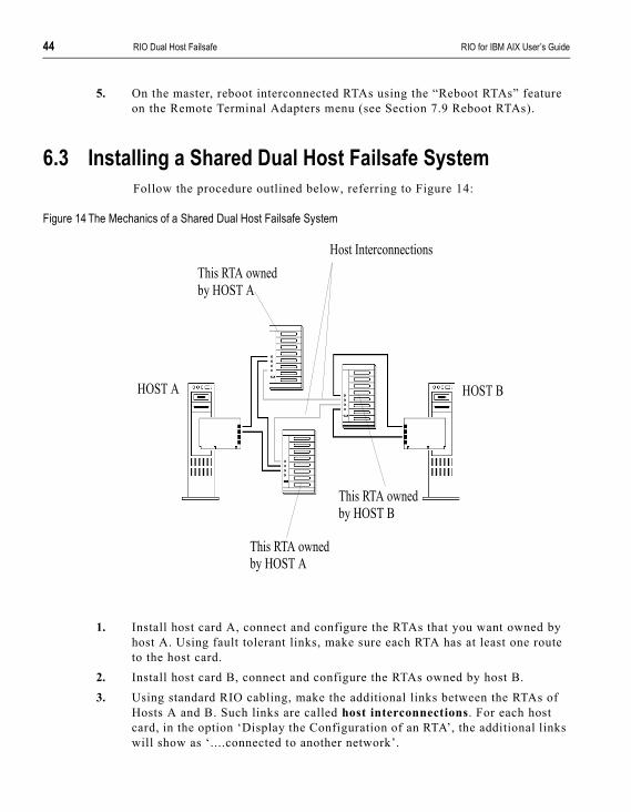
6.3 Installing a Shared Dual Host Failsafe SystemFollow the procedure outlined below, referring to Figure 14:
Figure 14 The Mechanics of a Shared Dual Host Failsafe System
1. Install host card A, connect and configure the RTAs that you want owned by host A. Using fault tolerant links, make sure each RTA has at least one route to the host card.
2. Install host card B, connect and configure the RTAs owned by host B.3. Using standard RIO cabling, make the additional links between the RTAs of
Hosts A and B. Such links are called host interconnections. For each host card, in the option ‘Display the Configuration of an RTA’, the additional links will show as ‘....connected to another network’.
HOST BHOST A
This RTA ownedby HOST A
Host Interconnections
This RTA ownedby HOST A
This RTA ownedby HOST B
RIO for IBM AIX User’s Guide RIO Dual Host Failsafe 45
4. Note the configuration settings (RTA and TTY) of each machine. We suggest you do this manually.
6.3.1 When one host fails:1. Ensure the failed machine is shutdown.2. Power cycle manually the RTAs connected to the failed machine. These RTAs
will then become adopted by the host card in the working machine.3. In the working machine go to the options ‘Add a Specialix RIO RTA’ and
‘Add a TTY’ and copy in the settings on the newly adopted RTAs 4. The working machine will be able to manage your RTA system while you
attend to the failed host.5. Leave in place the host interconnection links.6. While repairing the failed master host, when you power it up and down, the
RTAs will remain under the control of the working host.
6.3.2 When the failed host is available again:1. Ensure the repaired host is shutdown.2. Disconnect physically the host interconnection links. The RTAs will then be
attached only to their original host cards. Leave the power connections to the RTAs in place.
3. Turn on the repaired host. The RTAs will still be “owned” by the working host.
4. Reboot interconnected RTAs using the “Reboot RTAs” feature on the Remote Terminal Adapters menu (see Section 7.9 Reboot RTAs).
5. Re-connect the host interconnections. The two RIO systems should resume managing their own RTAs.

46 RIO Dual Host Failsafe RIO for IBM AIX User’s Guide
RIO for IBM AIX User’s Guide System Management 47
C h a p t e r 7
System Management
7.1 Draw RIO RTA Topology
7.2 Adding a Fault Tolerant Link
7.3 Link Failure or Disconnection
7.4 Adding a New RTA
7.5 Removing an RTA
7.6 Moving an RTA
7.7 List RTAs
7.8 Adopt New RTA
7.9 Reboot RTAs
7.10 Identify an RTA
7.11 Adding a Host Card
7.12 Removing a Host Card
7.13 Display the Configuration of a Host Card
7.14 List Host Cards
7.15 Save RIO Device Configuration
7.16 Load RIO Device Configuration
7.17 Remove all RIO Devices

48 System Management RIO for IBM AIX User’s Guide
7.1 Draw RIO RTA TopologyTo help you keep track of the RTAs in your RIO network, SMIT creates a diagrammatic illustration of each RIO system installed in your machine. These ‘RTA Topologies' show the host card, remote terminal adapters, RIO links and even the link sockets that each link cable is plugged into.
RTAs are detected as soon as they are connected. Before they are defined they are identified by their internal ID numbers.
1. Use the FastPath command smit rio to access the Specialix RIO menu. From this menu select ‘Remote Terminal Adapters'. The following menu will be displayed
2. Select ‘Draw Specialix RIO RTA Topology' and then select which RIO system you want to display. The RTA Topology for this host card will be displayed:
RIO Remote Terminal Adapter
Move cursor to desired item and press Enter.
List Specialix RIO RTAsAdd a Specialix RIO RTADraw Specialix RIO RTA TopologyAdopt new Specialix RIO RTAReboot Specialix RIO RTAsIdentify a Specialix RIO RTARemove a Specialix RIO RTA
F1=Help F2=Refresh F3=Cancel Esc+8=ImageEsc+9=Shell Esc+0=Exit Enter=Do

RIO for IBM AIX User’s Guide System Management 49
Figure 15 Example RIO configuration
Note If you have fault tolerant links installed, your RTA Topology may not look how you expect. See Section 7.2 Adding a Fault Tolerant Link.
D900001PCI Hostrio0A B C D| || |
+----------+ +------+| || |
A B C D A B C DRTA 16 RTA 16D900002 D900003rta0 rta4
| | || | |
+---------+ +-------+ +-----+| | || | |A B C D A B C D A B C DRTA 16 RTA 16 RTA 16D900004 D900005 D900006rta1 rta2 rta5
| || |
+---+ +-+| || |A B C D A B C DRTA 16 RTA 16D900007 D900001rta3 rta6
50 System Management RIO for IBM AIX User’s Guide
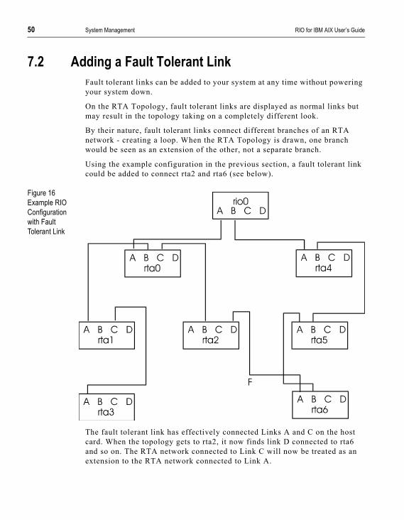
7.2 Adding a Fault Tolerant LinkFault tolerant links can be added to your system at any time without powering your system down.
On the RTA Topology, fault tolerant links are displayed as normal links but may result in the topology taking on a completely different look.
By their nature, fault tolerant links connect different branches of an RTA network - creating a loop. When the RTA Topology is drawn, one branch would be seen as an extension of the other, not a separate branch.
Using the example configuration in the previous section, a fault tolerant link could be added to connect rta2 and rta6 (see below).
Figure 16Example RIO Configuration with Fault Tolerant Link
The fault tolerant link has effectively connected Links A and C on the host card. When the topology gets to rta2, it now finds link D connected to rta6 and so on. The RTA network connected to Link C will now be treated as an extension to the RTA network connected to Link A.
RIO for IBM AIX User’s Guide System Management 51
The topology would not read the configuration again, in reverse order, from Link C on the host card.
7.3 Link Failure or DisconnectionIn the event of link failure or disconnection, data will either be buffered until the link is restored or re-routed automatically via a fault tolerant link. Data will not be lost (unless an RTA is switched off). If data is buffered, users will experience a delay.
Link failure can be diagnosed by looking at an RTA's LEDs or the RTA Topology.
The LED on a failed link will turn red (for about 20 seconds) and then die. If the RTA has been isolated by the link failure, the LED next to port 5 will die as well.
If you display the RTA Topology after a link has failed, you will find that the failed link and any isolated RTAs are not displayed. They will reappear, however, if the topology is redisplayed once the link has been restored.
Note The RTA Topology may be constructed differently if a fault tolerant link becomes an RTA's primary route to the host card. This effect is explained in Section 7.2 Adding a Fault Tolerant Link.
7.4 Adding a New RTARemote terminal adaptors can be added without powering your system down. They will be added to the RTA Topology automatically, initially recorded by their internal ID number. They must be defined in the database as normal (see Chapter 5 (Configuring RTAs).
You can install up to 128 ports on a host card using 8 and 16 port RTAs. Above this number, RTAs will be rejected.
Note If you have removed RTAs from the network without deleting them from the configuration as well, you may reach the point where RIO thinks there are sixteen RTAs installed when there aren't. See Section 7.5 Removing an RTA.
52 System Management RIO for IBM AIX User’s Guide
7.5 Removing an RTAYou can remove an RTA without having to power your system down. However, this causes the same effect as disconnecting a link cable so take care not to isolate any other RTAs. You can prevent RTA isolation by the use of fault tolerant links.
If you display the RTA topology you will notice that the removed RTA is no longer displayed. If you were to reconnect the RTA, and re-display the topology, the RTA would reappear.
To remove an RTA, type smit rio, select ‘Remote Terminal Adapter’, then select ‘Remove Remote Terminal Adapter’. More details are provided below.
7.5.1 Temporary RemovalIf you are removing the RTA to have it tested or repaired, you may want to bring it down to the ‘Defined' state in the configuration database. In this state, it won't be displayed on the topology. To do this, disconnect the RTA and reboot your machine. When the machine starts up again, the RTA and any devices assigned to it will have changed to the ‘Defined' state.
When you re-install the RTA, its internal ID will be automatically matched with the ‘saved' definition. Run the command mkdev -l <rta name> from the shell prompt to bring the RTA up to the ‘Available' state again. The associated ‘Defined' devices can be configured using the ‘Configure a Defined TTY' option (FastPath = smit tty); the associated ‘Defined' print devices can be configured using the ‘Configure a Defined Printer/Plotter' option (FastPath = smit pdp).
7.5.2 Permanent RemovalIf you are removing an RTA permanently it is important to delete it from the database as well. This will add the port numbers that were assigned to the RTA to the list of available port numbers. Furthermore, failing to delete RTAs from the configuration may cause the situation where RIO thinks that the maximum number of RTAs have been installed. In this situation, any new RTAs added to the system will be rejected. Deleting an RTA is described below.
RIO for IBM AIX User’s Guide System Management 53
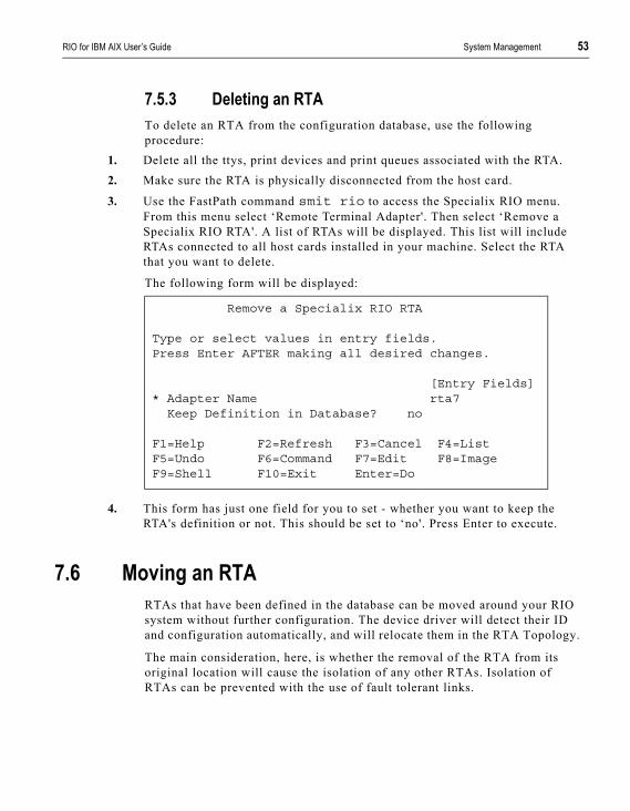
7.5.3 Deleting an RTATo delete an RTA from the configuration database, use the following procedure:
1. Delete all the ttys, print devices and print queues associated with the RTA.2. Make sure the RTA is physically disconnected from the host card.
3. Use the FastPath command smit rio to access the Specialix RIO menu. From this menu select ‘Remote Terminal Adapter'. Then select ‘Remove a Specialix RIO RTA'. A list of RTAs will be displayed. This list will include RTAs connected to all host cards installed in your machine. Select the RTA that you want to delete.
The following form will be displayed:
4. This form has just one field for you to set - whether you want to keep the RTA's definition or not. This should be set to ‘no'. Press Enter to execute.
7.6 Moving an RTARTAs that have been defined in the database can be moved around your RIO system without further configuration. The device driver will detect their ID and configuration automatically, and will relocate them in the RTA Topology.
The main consideration, here, is whether the removal of the RTA from its original location will cause the isolation of any other RTAs. Isolation of RTAs can be prevented with the use of fault tolerant links.
Remove a Specialix RIO RTA
Type or select values in entry fields.Press Enter AFTER making all desired changes.
[Entry Fields]* Adapter Name rta7
Keep Definition in Database? no
F1=Help F2=Refresh F3=Cancel F4=ListF5=Undo F6=Command F7=Edit F8=ImageF9=Shell F10=Exit Enter=Do
54 System Management RIO for IBM AIX User’s Guide
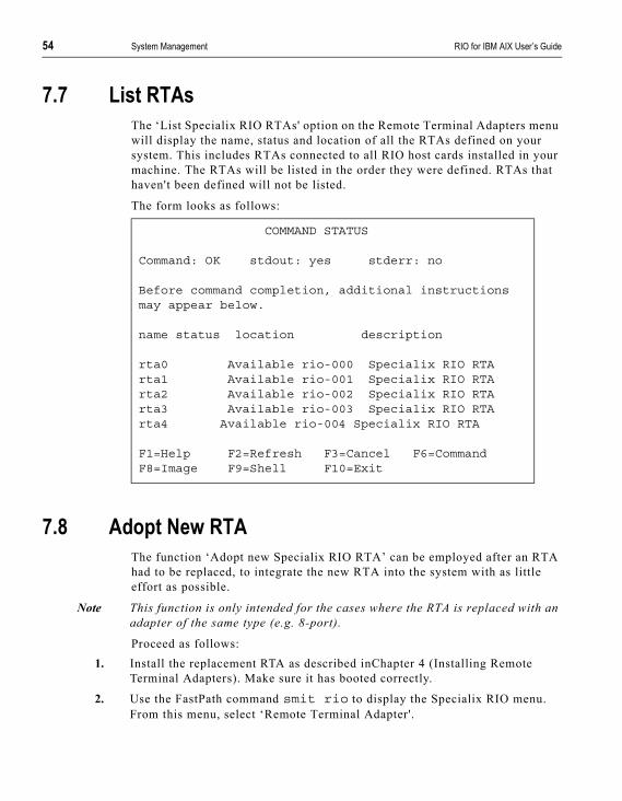
7.7 List RTAsThe ‘List Specialix RIO RTAs' option on the Remote Terminal Adapters menu will display the name, status and location of all the RTAs defined on your system. This includes RTAs connected to all RIO host cards installed in your machine. The RTAs will be listed in the order they were defined. RTAs that haven't been defined will not be listed.
The form looks as follows:
7.8 Adopt New RTAThe function ‘Adopt new Specialix RIO RTA’ can be employed after an RTA had to be replaced, to integrate the new RTA into the system with as little effort as possible.
Note This function is only intended for the cases where the RTA is replaced with an adapter of the same type (e.g. 8-port).
Proceed as follows:1. Install the replacement RTA as described inChapter 4 (Installing Remote
Terminal Adapters). Make sure it has booted correctly.
2. Use the FastPath command smit rio to display the Specialix RIO menu. From this menu, select ‘Remote Terminal Adapter'.
COMMAND STATUS
Command: OK stdout: yes stderr: no
Before command completion, additional instructionsmay appear below.
name status location description
rta0 Available rio-000 Specialix RIO RTArta1 Available rio-001 Specialix RIO RTArta2 Available rio-002 Specialix RIO RTArta3 Available rio-003 Specialix RIO RTArta4 Available rio-004 Specialix RIO RTA
F1=Help F2=Refresh F3=Cancel F6=CommandF8=Image F9=Shell F10=Exit

RIO for IBM AIX User’s Guide System Management 55
3. In the menu ‘RIO Remote Terminal Adapter’ select ‘Adopt new Specialix RIO RTA’
4. You are prompted for the old RTA name5. Select the old RTA name, and then select the unique ID name of the
replacement RTA.6. Once booted again, the new RTA will be integrated into the system after its
next reboot.
7.9 Reboot RTAsRTAs may need to be rebooted after a reorganisation of links or after a Dual Host Failsafe operation.
1. Use the FastPath command smit rio to display the Specialix RIO menu. From this menu, select ‘Remote Terminal Adapters'.
2. Select ‘Reboot Specialix RTAs’, and then press Enter.3. You are prompted to select one of the two options:
a. Reboot Connected RTAs(Connected RTAs have a known route to the host that booted them.)
b. Reboot Interconnected RTAs(Interconnected RTAs no longer have a route to the host that booted them, e.g. after a Dual Host Failsafe operation.)
7.10 Identify an RTAThis function helps to identify which physical RTA is associated with which name (e.g. RTA0).
Proceed as follows:
1. Use the FastPath command smit rio to display the Specialix RIO menu. From this menu, select ‘Remote Terminal Adapter'.
2. Select ‘Identify Specialix RIO RTAs’3. Select the name of the RTA you want to identify
The LEDs on the RTA associated with the selected name will flash until the Enter key is pressed.
56 System Management RIO for IBM AIX User’s Guide
7.11 Adding a Host CardIf you are going to install another RIO host card (i.e. another RIO system) you must shut down AIX and switch your machine off. Install the host card as described in Chapter 3 (Installing the Host Card).
7.12 Removing a Host CardBefore removing a host card you must shut down AIX and switch your machine off.
When the machine has been rebooted, the host card will be flagged as ‘Defined'. If you subsequently re-install the host card it will be matched up with its saved definition.
If you are removing the host card permanently, or replacing it with a new card, you should delete the definition of the host card from the device configuration database. This is described below:
7.12.1 Deleting a Host CardTo delete a host card from the configuration database, use the following procedure (see Section 7.5 Removing an RTA).
1. Delete all the RTAs associated with the host card from the configuration database.
2. Use the command smit rio to display the Specialix RIO menu. From this menu, select ‘Host Adaptor'. From the ‘Host Adaptor' menu, select ‘Remove a RIO Adaptor'. A list of your host cards will be displayed; select the one you want to delete. The following form will be displayed:
Delete A RIO Host Adaptor
Type or select values in entry fields.Press Enter AFTER making all desired changes.
[Entry Fields]*Adaptor Device rio0Keep Definition? yes
F1=Help F2=Refresh F3=Cancel F4=ListF5=Undo F6=Command F7=Edit F8=ImageF9=Shell F10=Exit Enter=Do
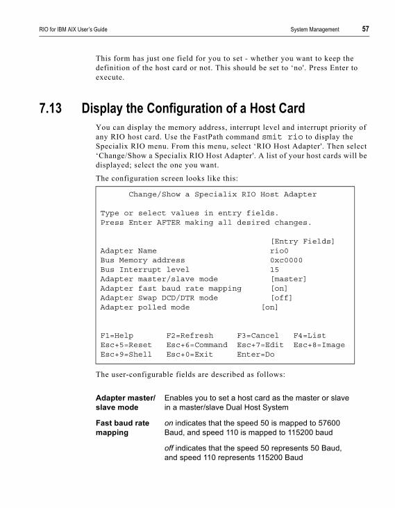
RIO for IBM AIX User’s Guide System Management 57
This form has just one field for you to set - whether you want to keep the definition of the host card or not. This should be set to ‘no'. Press Enter to execute.
7.13 Display the Configuration of a Host CardYou can display the memory address, interrupt level and interrupt priority of any RIO host card. Use the FastPath command smit rio to display the Specialix RIO menu. From this menu, select ‘RIO Host Adapter'. Then select ‘Change/Show a Specialix RIO Host Adapter'. A list of your host cards will be displayed; select the one you want.
The configuration screen looks like this:
The user-configurable fields are described as follows:
Change/Show a Specialix RIO Host Adapter
Type or select values in entry fields.Press Enter AFTER making all desired changes.
[Entry Fields]Adapter Name rio0Bus Memory address 0xc0000Bus Interrupt level 15Adapter master/slave mode [master]Adapter fast baud rate mapping [on]Adapter Swap DCD/DTR mode [off]Adapter polled mode [on]
F1=Help F2=Refresh F3=Cancel F4=ListEsc+5=Reset Esc+6=Command Esc+7=Edit Esc+8=ImageEsc+9=Shell Esc+0=Exit Enter=Do
Adapter master/slave mode
Enables you to set a host card as the master or slave in a master/slave Dual Host System
Fast baud rate mapping
on indicates that the speed 50 is mapped to 57600 Baud, and speed 110 is mapped to 115200 baud
off indicates that the speed 50 represents 50 Baud, and speed 110 represents 115200 Baud

58 System Management RIO for IBM AIX User’s Guide
7.14 List Host CardsYou can list the RIO host cards installed in your machine. The list will include the name, status and location (in the machine) of each host card.
Use the smit rio command to display the Specialix RIO menu. From this menu, select the ‘RIO Host Adapter' option. From the RIO Host Adapter menu, select ‘List All RIO Adapters'. Your host cards will be listed:
Host cards are listed in the order that they were installed.
The status of a host card can be ‘Available' or ‘Defined'. If ‘Available', the host card is installed and configured. If ‘Defined' the host card has been removed but the definition saved in the database.
Swap DTR/DCD Mode
This option defines whether it is the logic on pin 20 (DCD) or the one on pin 8 (DCD) that sends SIGHUP.
Polled mode Forces the host card to use software timeouts instead of interrupt requests.
COMMAND STATUS
Command: OK stdout: yes stderr: no
Before command completion, additional instructions mayappear below.
name status location descriptionrio0 Available 00-01x Specialix RIO Host Adapter (PCI)rio1 Available 00-02x Specialix RIO Host Adapter (PCI)
F1=Help F2=Refresh F3=Cancel F6=CommandF8=Image F9=Shell F10=Exit
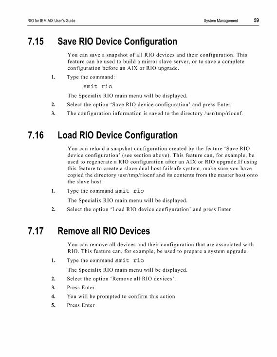
RIO for IBM AIX User’s Guide System Management 59
7.15 Save RIO Device ConfigurationYou can save a snapshot of all RIO devices and their configuration. This feature can be used to build a mirror slave server, or to save a complete configuration before an AIX or RIO upgrade.
1. Type the command:
smit rio
The Specialix RIO main menu will be displayed.2. Select the option ‘Save RIO device configuration’ and press Enter.3. The configuration information is saved to the directory /usr/tmp/riocnf.
7.16 Load RIO Device ConfigurationYou can reload a snapshot configuration created by the feature ‘Save RIO device configuration’ (see section above). This feature can, for example, be used to regenerate a RIO configuration after an AIX or RIO upgrade.If using this feature to create a slave dual host failsafe system, make sure you have copied the directory /usr/tmp/riocnf and its contents from the master host onto the slave host.
1. Type the command smit rio
The Specialix RIO main menu will be displayed.2. Select the option ‘Load RIO device configuration’ and press Enter
7.17 Remove all RIO DevicesYou can remove all devices and their configuration that are associated with RIO. This feature can, for example, be used to prepare a system upgrade.
1. Type the command smit rio
The Specialix RIO main menu will be displayed.2. Select the option ‘Remove all RIO devices’.3. Press Enter4. You will be prompted to confirm this action5. Press Enter

60 System Management RIO for IBM AIX User’s Guide

RIO for IBM AIX, User’s Guide Port Specifications & Cabling 61
A p p e n d i x A
Port Specifications & Cabling
A.1 OverviewThis appendix describes pin specifications of the various types of connectors. It also guides you in cabling your devices to equipment.
The contents of this appendix is pin specifications,example connections for most Perle connectors, and various RIO product cabling specifications.
Pin specifications:
• RS232 DB25 Ports (Female) DCE Section A.2
• RS232 DB25 Ports (Male) DTE Section A.3
• RS232* (asterisk) DB25 Ports Section A.4
• RS232 RJ45 ports (with shielded connector) Section A.5
• RJ45 Ports (no shielding) Section A.6
• Parallel DB25 Port Section A.33
• RS232 RJ45 Opto-isolated Ports Section A.34
• RS422 DB25 Ports Section A.35
62 Port Specifications & Cabling RIO for IBM AIX, User’s Guide
Connection examples:• for Direct (1:1) connections, see mini-Table of Contents at
Section A.8.1.
• for Structured Cabling Systems, see mini-Table of Contents at Section A.23.1
RIO product cabling specifications:
• RIO Long Distance Unit (LDU) Section A.30
• RIO Link Cable Section A.31
• Fibre Optic Cable Section A.32
RIO for IBM AIX, User’s Guide Port Specifications & Cabling 63
A.2 RS232 DB25 Ports (Female) DCEThese ports provide a full RS232 interface for serial devices. The female DB25 connectors are wired as RS232 Data Communications Equipment (DCE).
Use a straight through cable to be used when connecting to DTE devices such as terminals. When connecting to other DCE devices, such as modems, a crossover cable must be used. Connection examples are shown in:
Section A.7 Direct (1:1) Connections, Example Connections, andSection A.22 Structured Cabling Systems, Example Connections.
The RS232 DB25 DCE serial pinouts are:
Table 6RS232 DB25 (female) pin-outs
Notes:
1. P/GND means Protective (Chassis) Ground
2. S/GND means Signal Ground
Note: Optionally you can order these ports with surge suppression. This feature enables the ports to absorb high static discharges and surges. Contact your supplier for more information.
Pin Circuit Direction Function1 P/GND - Connect to case2 RXD Input Receive Data3 TXD Output Transmit Data4 RTS Input Transmit Hardware Flow Control5 CTS Output Receive Hardware Flow Control6 DSR Output Data Set Ready7 S/GND - Connect to logic 0V8 DCD Input Data Carrier Detect20 DTR Input Data Terminal Ready22 RI Input Ring Indicator

64 Port Specifications & Cabling RIO for IBM AIX, User’s Guide
A.3 RS232 DB25 Ports (Male) DTEThese ports provide a full RS232 interface for serial devices. The male DB25 connectors are wired as RS232 Data Terminal Equipment (DTE).
You can use straight (pin 1 to pin 1, etc.) connections to Data Communications Equipment (DCE) such as modems. When connecting to other DTE devices, such as terminals, a crossover cable or device must be used. Connection examples are shown in:
Section A.7 Direct (1:1) Connections, Example Connections, andSection A.22 Structured Cabling Systems, Example Connections.
The RS232 DB25 DTE serial pin-outs are:
Table 7RS232 DB25 (male) pin-outs
Notes:
1. P/GND means Protective (Chassis) Ground
2. S/GND means Signal Ground
Note: Optionally you can order these ports with surge suppression. This feature enables the ports to absorb high static discharges and surges. Contact your supplier for more information.
Pin Circuit Direction Function1 P/GND — Connect to case2 TXD Output Transmit Data3 RXD Input Receive Data4 RTS Output Receive Hardware Flow Control5 CTS Input Transmit Hardware Flow Control6 DSR Input Data Set Ready7 S/GND — Connect to logic 0V8 DCD Input Data Carrier Detect20 DTR Output Data Terminal Ready22 RI Input Ring Indicator
RIO for IBM AIX, User’s Guide Port Specifications & Cabling 65
A.4 RS232* (asterisk) DB25 Ports
On the casing of your product, you may have DB25 ports marked with an asterisk after the letters RS232. These RS232 ports have reduced capability: they do not support the Ring Indicator (RI) or Data Terminal Ready (DTR) signals. When cabling your devices to a RS232* port, bear in mind this limitation.
See pin-out details for DB25 connectors in Table 6 or Table 7.
The RS232 * ports are part of an option where a parallel port is provided; see Figure 17. One of the ports in the group is a parallel port.
Figure 17 RS232* ports
Note: As an option you can have order the RS232* ports with surge suppression capability. This feature allows the ports to absorb high static discharges and surges.

66 Port Specifications & Cabling RIO for IBM AIX, User’s Guide
A.5 RS232 RJ45 ports (with shielded connector)The shielded RS232 RJ45 ports comply with the RS232 specification.
Note: (There is an older non-shielded version of these ports; see Section A.6 RJ45 Ports (no shielding).
Connection examples are shown in:
Section A.7 Direct (1:1) Connections, Example Connections, andSection A.22 Structured Cabling Systems, Example Connections.
The pin-outs are shown in Table 8.
Table 8shielded RJ45 pin-outs
Caution: the pin-outs above are different from those of the earlier version of these ports, the RJ45 non-shielded ports.
Notes:
1. P/GND means Protective (Chassis) Ground
2. S/GND means Signal Ground
Note: Optionally you can order these ports with surge suppression. This feature enables the ports to absorb high static discharges and surges. Contact your supplier for more information.
Pin Circuit Direction Function1 DCD Input Data Carrier Detect2 DSR Output Data Set Ready3 DTR Input Data Terminal Ready4 S/GND — Signal Ground5 TXD Output Transmit Data6 RXD Input Receive Data7 CTS Output Clear To Send8 RTS Input Request To SendShield P/GND — Protective (Chassis) Ground

RIO for IBM AIX, User’s Guide Port Specifications & Cabling 67
The pins in the RJ45 socket are located at the top, with pin 1 on the left (see Figure 18).
Viewing the RJ45 plug from above (with the clip underneath), the pins are numbered as follows:
Figure 18RJ45 Pin Numbering
Pins1 2 3 4 5 6 7 8
Wires
Cable

68 Port Specifications & Cabling RIO for IBM AIX, User’s Guide
A.6 RJ45 Ports (no shielding)These RJ45 ports do not have shielding around the connector.
Caution: these ports are being phased out. Their replacement are the shielded RJ45 ports; (see Section A.5 RS232 RJ45 ports (with shielded connector)).
The pin-outs are as follows:
Table 9non-shielded RJ45 pin-outs
Notes:
1. S/GND means Signal Ground
To determine the position of pins inside the connector, see Figure 18.
Pin Circuit Direction Function1 DSR Output Data Set Ready2 DCD Input Data Carrier Detect3 RXD Input Receive Data4 CTS Output Receive Hardware Flow Control5 S/GND — Ground6 TXD Output Transmit Data7 DTR Input Data Terminal Ready8 RTS Input Receive Hardware Flow Control
RIO for IBM AIX, User’s Guide Port Specifications & Cabling 69
A.7 Direct (1:1) ConnectionsThis section details direct (1:1) connections (definition below). For structured cabling systems, go toSection A.22 Structured Cabling Systems.
Definition of a Direct (1:1) connection:
a single length of cable joins the device and your equipment; there is no structured cabling system or any other connection in-between.
Notes:
1. Some user equipment need additional signals on the connector. These may not be supported by the Perle device or your cable. The normal way to overcome this is to loop-back - on your equipment - one of the output lines to the required input. Refer to the documentation supplied with your equipment, or the supplier of the equipment, for information on which loop-backs, if any, are required.
2. Other than a specific requirement at your equipment (as in note 1), do not connect unused pins on either connector.
3. On the DB25 connector, Protective Ground (P/GND) is pin 1. On the RJ45 connector, Protective Ground (P/GND) terminates on the connector and so does not have a pin number.
A.8.1 Example ConnectionsIn this section we show example connections between Perle ports and the following devices:
Terminals
Terminals (slow speed or using software flow control)
Section A.10.1
Terminals (faster speed or using Hardware Flow Control)
Section A.11.2
Terminal Connection using the modem device, Without hardware flow control:
Section A.13.1

70 Port Specifications & Cabling RIO for IBM AIX, User’s Guide
Terminal Connection using the modem device, With hardware flow control:
Section A.14.2
Modems
direct (1:1) connections: Section A.16.1
PCs (DB9 connectors)
PCs (DB9 connectors) Section A.17
Serial Printers
with software flow control Section A.19.1
with hardware flow control Section A.20.2
Terminals
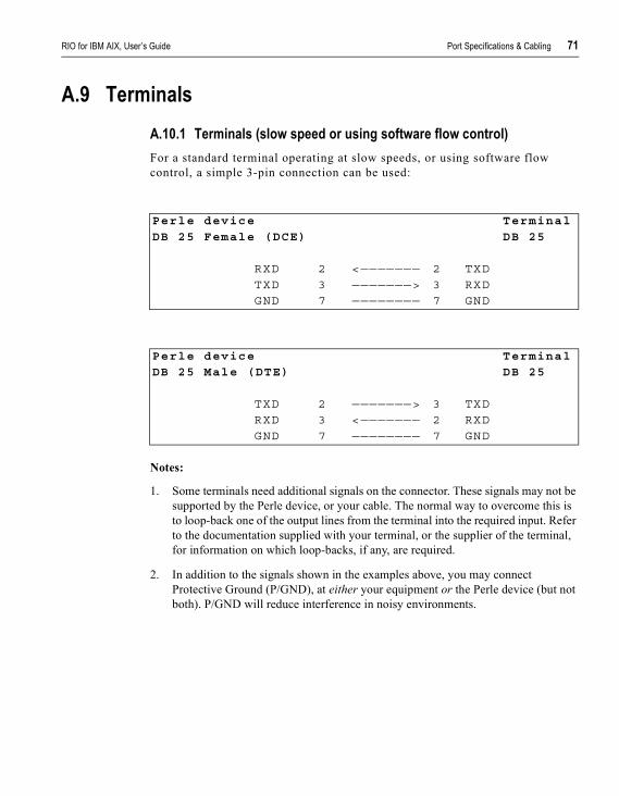
RIO for IBM AIX, User’s Guide Port Specifications & Cabling 71
A.9 TerminalsA.10.1 Terminals (slow speed or using software flow control)For a standard terminal operating at slow speeds, or using software flow control, a simple 3-pin connection can be used:
Notes:
1. Some terminals need additional signals on the connector. These signals may not be supported by the Perle device, or your cable. The normal way to overcome this is to loop-back one of the output lines from the terminal into the required input. Refer to the documentation supplied with your terminal, or the supplier of the terminal, for information on which loop-backs, if any, are required.
2. In addition to the signals shown in the examples above, you may connect Protective Ground (P/GND), at either your equipment or the Perle device (but not both). P/GND will reduce interference in noisy environments.
Perle device Terminal
DB 25 Female (DCE) DB 25
RXD 2 <——————— 2 TXDTXD 3 ———————> 3 RXDGND 7 ———————— 7 GND
Perle device Terminal
DB 25 Male (DTE) DB 25
TXD 2 ———————> 3 TXDRXD 3 <——————— 2 RXDGND 7 ———————— 7 GND
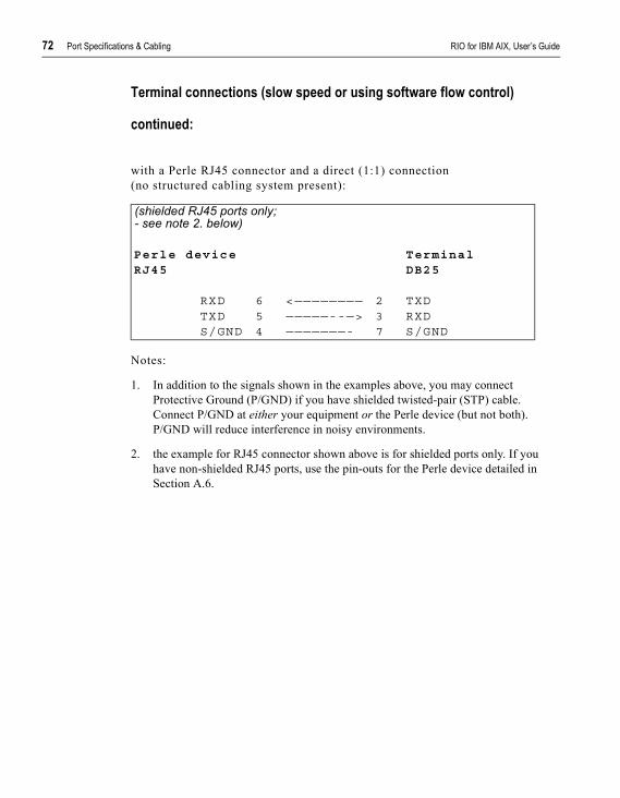
72 Port Specifications & Cabling RIO for IBM AIX, User’s Guide
Terminal connections (slow speed or using software flow control)
continued:
with a Perle RJ45 connector and a direct (1:1) connection(no structured cabling system present):
Notes:
1. In addition to the signals shown in the examples above, you may connect Protective Ground (P/GND) if you have shielded twisted-pair (STP) cable. Connect P/GND at either your equipment or the Perle device (but not both). P/GND will reduce interference in noisy environments.
2. the example for RJ45 connector shown above is for shielded ports only. If you have non-shielded RJ45 ports, use the pin-outs for the Perle device detailed in Section A.6.
(shielded RJ45 ports only;- see note 2. below)
Perle device TerminalRJ45 DB25
RXD 6 <———————— 2 TXDTXD 5 —————--—> 3 RXDS/GND 4 ———————- 7 S/GND

RIO for IBM AIX, User’s Guide Port Specifications & Cabling 73
A.11.2 Terminals(faster speed or using Hardware Flow Control)
For a slow terminal operating at speeds faster than 9600 baud, or for a terminal which can’t use xon/xoff flow control, the following connections are required:
:
Notes:
1. * asterisk denotes that you should connect these pins only if input (from the Terminal to the Perle device) flow control is required.
2. the pins used for hardware flow control may vary from terminal to terminal, but RTS (pin 4) on the Perle device port must be connected to the pin on the terminal which indicates that the terminal buffer is full.
3. In addition to the signals shown in the examples above, you may connect Protective Ground (P/GND), at either your equipment or the Perle device (but not both). P/GND will reduce interference in noisy environments.
Perle device Terminal
DB25 Female (DCE) DB25
RXD 2 <——————— 2 TXDTXD 3 ———————> 3 RXDRTS 4 <——————— 4 or 20 RTS/
DTR*CTS 5 ———————> 5 *CTSGND 7 ——————— 7 GND
Perle device Terminal
DB25 Male (DTE) DB25
TXD 2 ———————> 3 RXDRXD 3 <——————— 2 TXD*RTS 4 ———————> 5 *CTSCTS 5 <——————— 4 or
20RTS/DTR
GND 7 ——————— 7 GND

74 Port Specifications & Cabling RIO for IBM AIX, User’s Guide
4. Some terminals need additional signals on the connector. These may not be supported by the Perle device, or your cable. The normal way to overcome this is to loopback one of the output lines from the terminal into the required input. Refer to the documentation supplied with your terminal, or the supplier of the terminal, for information on which loop-backs, if any, are required.
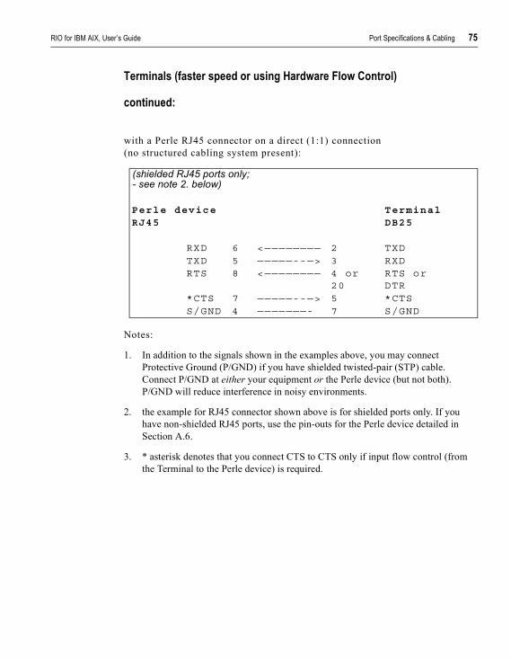
RIO for IBM AIX, User’s Guide Port Specifications & Cabling 75
Terminals (faster speed or using Hardware Flow Control)
continued:
with a Perle RJ45 connector on a direct (1:1) connection(no structured cabling system present):
Notes:
1. In addition to the signals shown in the examples above, you may connect Protective Ground (P/GND) if you have shielded twisted-pair (STP) cable. Connect P/GND at either your equipment or the Perle device (but not both). P/GND will reduce interference in noisy environments.
2. the example for RJ45 connector shown above is for shielded ports only. If you have non-shielded RJ45 ports, use the pin-outs for the Perle device detailed in Section A.6.
3. * asterisk denotes that you connect CTS to CTS only if input flow control (from the Terminal to the Perle device) is required.
(shielded RJ45 ports only;- see note 2. below)
Perle device TerminalRJ45 DB25
RXD 6 <———————— 2 TXDTXD 5 —————--—> 3 RXDRTS 8 <———————— 4 or
20RTS orDTR
*CTS 7 —————--—> 5 *CTSS/GND 4 ———————- 7 S/GND
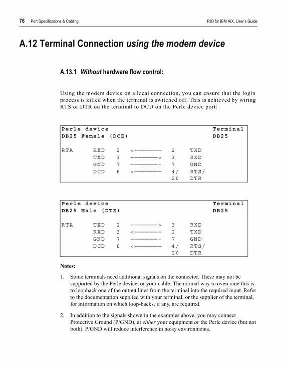
76 Port Specifications & Cabling RIO for IBM AIX, User’s Guide
A.12 Terminal Connection using the modem device
A.13.1 Without hardware flow control:
Using the modem device on a local connection, you can ensure that the login process is killed when the terminal is switched off. This is achieved by wiring RTS or DTR on the terminal to DCD on the Perle device port:
Notes:
1. Some terminals need additional signals on the connector. These may not be supported by the Perle device, or your cable. The normal way to overcome this is to loopback one of the output lines from the terminal into the required input. Refer to the documentation supplied with your terminal, or the supplier of the terminal, for information on which loop-backs, if any, are required.
2. In addition to the signals shown in the examples above, you may connect Protective Ground (P/GND), at either your equipment or the Perle device (but not both). P/GND will reduce interference in noisy environments.
Perle device TerminalDB25 Female (DCE) DB25
RTA RXD 2 <——————— 2 TXDTXD 3 ———————> 3 RXDGND 7 ———————- 7 GNDDCD 8 <——————— 4/
20RTS/DTR
Perle device TerminalDB25 Male (DTE) DB25
RTA TXD 2 ———————> 3 RXDRXD 3 <——————— 2 TXDGND 7 ———————- 7 GNDDCD 8 <——————— 4/
20RTS/DTR
RIO for IBM AIX, User’s Guide Port Specifications & Cabling 77
Terminal Connection using the modem device
Without hardware flow control
(continued)
with a Perle RJ45 connector on a direct (1:1) connection(no structured cabling system present):
Notes:
1. In addition to the signals shown in the examples above, you may connect Protective Ground (P/GND) if you have shielded twisted-pair (STP) cable. Connect P/GND at either your equipment or the Perle device (but not both). P/GND will reduce interference in noisy environments.
2. the example for RJ45 connector shown above is for shielded RJ45 ports only. If you have non-shielded RJ45 ports use the pin-outs for the Perle device detailed in Section A.6.
(shielded RJ45 ports only;- see note 2. below)
Perle device TerminalRJ45 DB25
RXD 6 <———————— 2 TXDTXD 5 —————--—> 3 RXDS/GND 4 ———————- 7 S/GNDDCD 1 <———————— 4/
20RTS/DTR
78 Port Specifications & Cabling RIO for IBM AIX, User’s Guide
Terminal Connection using the modem device
A.14.2 With hardware flow control:
Using the modem device on a local connection, you can ensure that the login process is killed when the terminal is switched off. This is achieved by wiring RTS on the terminal to DCD on the Perle device port:
Notes:
1. The above examples assume that DTR on the terminal is being used for hardware flow control.
If you are using RTS on the terminal as the hardware flow control pin, connect DTR on the Terminal to DCD on the Perle device, and connect RTS on the terminal to either RTS or CTS on the Perle device (RTS if Perle connector is female (wired as DCE); CTS if Perle connector is male (wired as DTE)).
2. In addition to the signals shown in the examples above, you may connect Protective Ground (P/GND), at either your equipment or the Perle device (but not both). P/GND will reduce interference in noisy environments.
Perle device TerminalDB25 Female (DCE) DB25
RXD 2 <——————— 2 TXDTXD 3 ———————> 3 RXDRTS 4 <——————— 20 DTRGND 7 ———————— 7 GNDDCD 8 <——————— 4 RTS
Perle device TerminalDB25 Male (DTE) DB25
TXD 2 ———————> 3 RXDRXD 3 <——————— 2 TXDCTS 5 <——————— 20 DTRGND 7 ———————- 7 GNDDCD 8 <——————— 4 RTS

RIO for IBM AIX, User’s Guide Port Specifications & Cabling 79
3. If your terminal still needs additional signals on the connector, note that these signals may not be supported by the Perle device, or your cable. The normal way to overcome this is to loopback one of the output lines from the terminal into the required input. Refer to the documentation supplied with your terminal, or the supplier of the terminal, for information on which loop-backs, if any, are required.
80 Port Specifications & Cabling RIO for IBM AIX, User’s Guide
Terminal Connection using the modem device
With hardware flow control:
(continued)
with a Perle RJ45 connector on a direct (1:1) connection(no structured cabling system present):
Notes:
1. In addition to the signals shown in the examples above, you may connect Protective Ground (P/GND) if you have shielded twisted-pair (STP) cable. Connect P/GND at either your equipment or the Perle device (but not both). P/GND will reduce interference in noisy environments.
2. the example for RJ45 connector shown above is for shielded RJ45 ports only. If you have a non-shielded RJ45 ports, use the pin-outs for the Perle device detailed in Section A.6.
3. The above example assumes that DTR on the terminal is being used for hardware flow control.
If you are using RTS on the terminal as the hardware flow control pin, connect DTR on the Terminal to DCD on the Perle device, and connect RTS on the terminal to RTS on the Perle device.
(shielded RJ45 ports only;- see note 2. below)
Perle device TerminalRJ45 DB25
RXD 6 <———————— 2 TXDTXD 5 —————--—> 3 RXDRTS 8 <———————— 20 DTRS/GND 4 ———————- 7 S/GNDDCD 1 <———————— 4 RTS

RIO for IBM AIX, User’s Guide Port Specifications & Cabling 81
A.15 Modems
A.16.1 direct (1:1) connections:
Notes:
1. In addition to the signals shown in the examples above, you may connect Protective Ground (P/GND), at either your equipment or the Perle device (but not both). P/GND will reduce interference in noisy environments.
Perle device Modem
DB25 Female (DCE) DB25
RXD 2 <——————— 3 RXD ModemTXD 3 ———————> 2 TXDRTS 4 <——————— 5 CTSCTS 5 ———————> 4 RTSDSR 6 ———————> 20 DTRGND 7 ——————— 7 GNDDCD 8 <——————— 8 DCDDTR 20 <——————— 6 DSR
Perle device Modem
DB25 Male (DTE) DB25
TXD 2 ———————> 2 TXD Modem
RXD 3 <——————— 3 RXDRTS 4 ———————> 4 RTSCTS 5 <——————— 5 CTSDSR 6 <——————— 6 DSRGND 7 ——————— 7 GNDDCD 8 <——————— 8 DCDDTR 20 ———————> 20 DTR
82 Port Specifications & Cabling RIO for IBM AIX, User’s Guide
Modems; example connections,
continued:
with a Perle RJ45 connector and a direct (1:1) connection to the modem(no structured cabling system present):
Notes:
1. at the modem, signal RXD is received data from the PSTN; signal TXD is transmitted data to the PSTN.
2. In addition to the signals shown in the examples above, you may connect Protective Ground (P/GND) if you have shielded twisted-pair (STP) cable. Connect P/GND at either your equipment or the Perle device (but not both). P/GND will reduce interference in noisy environments.
3. the example for RJ45 connector shown above is for shielded RJ45 ports only. If you have non-shielded RJ45 ports use the pin-outs for the Perle device detailed in Section A.6.
(shielded RJ45 ports only;- see note 2. below)
Perle device ModemRJ45 DB25
RXD 6 <———————— 3 RXDTXD 5 —————--—> 2 TXDRTS 8 <———————— 5 CTSCTS 7 —————--—> 4 RTSDSR 2 —————--—> 20 DTRS/GND 4 ———————- 7 S/GNDDCD 1 <———————— 8 DCDDTR 3 <———————— 6 DSR

RIO for IBM AIX, User’s Guide Port Specifications & Cabling 83
A.17 PCs (DB9 connectors)
direct (1:1) connections:
Note:
1. In addition to the signals shown in the examples above, you may connect Protective Ground (P/GND), at either your equipment or the Perle device (but not both). P/GND will reduce interference in noisy environments.
2. if your PC is fitted with a DB25 connector, use the same DB25 pin-outs as for modems, shown in Section A.15 Modems
Perle device PC
DB25 Female (DCE) DB9
TXD 3 ———————> 2 RXD PC
RXD 2 <——————— 3 TXDCTS 5 ———————> 8 CTSRTS 4 <——————— 7 RTSGND 7 ——————— 5 GNDDTR 20 <——————— 4 DTRDSR 6 ———————> 6 DSR
Perle device PC
DB25 Male (DTE) DB9
TXD 2 ———————> 2 RXD PCRXD 3 <——————— 3 TXDRTS 4 ———————> 8 CTSCTS 5 <——————— 7 RTSGND 7 ——————— 5 GND
DSR 6 <——————— 4 DTRDTR 20 ———————> 6 DSR
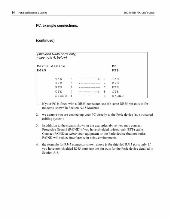
84 Port Specifications & Cabling RIO for IBM AIX, User’s Guide
PC, example connections,
(continued):
1. if your PC is fitted with a DB25 connector, use the same DB25 pin-outs as for modems, shown in Section A.15 Modems
2. we assume you are connecting your PC directly to the Perle device (no structured cabling system).
3. In addition to the signals shown in the examples above, you may connect Protective Ground (P/GND) if you have shielded twisted-pair (STP) cable. Connect P/GND at either your equipment or the Perle device (but not both). P/GND will reduce interference in noisy environments.
4. the example for RJ45 connector shown above is for shielded RJ45 ports only. If you have non-shielded RJ45 ports use the pin-outs for the Perle device detailed in Section A.6.
(shielded RJ45 ports only;- see note 4. below)
Perle device PCRJ45 DB9
TXD 5 —————--—> 3 TXDRXD 6 <———————— 2 RXDRTS 8 <———————— 7 RTSCTS 7 —————--—> 8 CTSS/GND 4 ———————- 5 S/GND
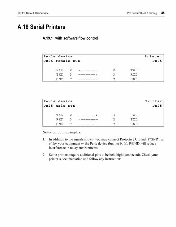
RIO for IBM AIX, User’s Guide Port Specifications & Cabling 85
A.18 Serial PrintersA.19.1 with software flow control
Notes on both examples:
1. In addition to the signals shown, you may connect Protective Ground (P/GND), at either your equipment or the Perle device (but not both). P/GND will reduce interference in noisy environments.
2. Some printers require additional pins to be held high (connected). Check your printer’s documentation and follow any instructions.
Perle device Printer
DB25 Female DCE DB25
RXD 2 <——————— 2 TXDTXD 3 ———————> 3 RXDGND 7 ———————— 7 GND
Perle device Printer
DB25 Male DTE DB25
TXD 2 ———————> 3 RXDRXD 3 <——————— 2 TXDGND 7 ———————— 7 GND
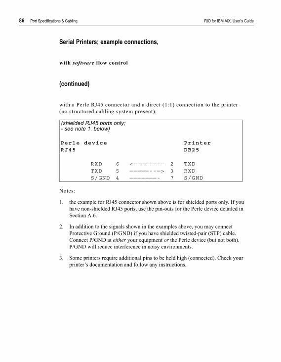
86 Port Specifications & Cabling RIO for IBM AIX, User’s Guide
Serial Printers; example connections,
with software flow control
(continued)
with a Perle RJ45 connector and a direct (1:1) connection to the printer(no structured cabling system present):
Notes:
1. the example for RJ45 connector shown above is for shielded ports only. If you have non-shielded RJ45 ports, use the pin-outs for the Perle device detailed in Section A.6.
2. In addition to the signals shown in the examples above, you may connect Protective Ground (P/GND) if you have shielded twisted-pair (STP) cable. Connect P/GND at either your equipment or the Perle device (but not both). P/GND will reduce interference in noisy environments.
3. Some printers require additional pins to be held high (connected). Check your printer’s documentation and follow any instructions.
(shielded RJ45 ports only;- see note 1. below)
Perle device PrinterRJ45 DB25
RXD 6 <———————— 2 TXDTXD 5 —————--—> 3 RXDS/GND 4 ———————- 7 S/GND
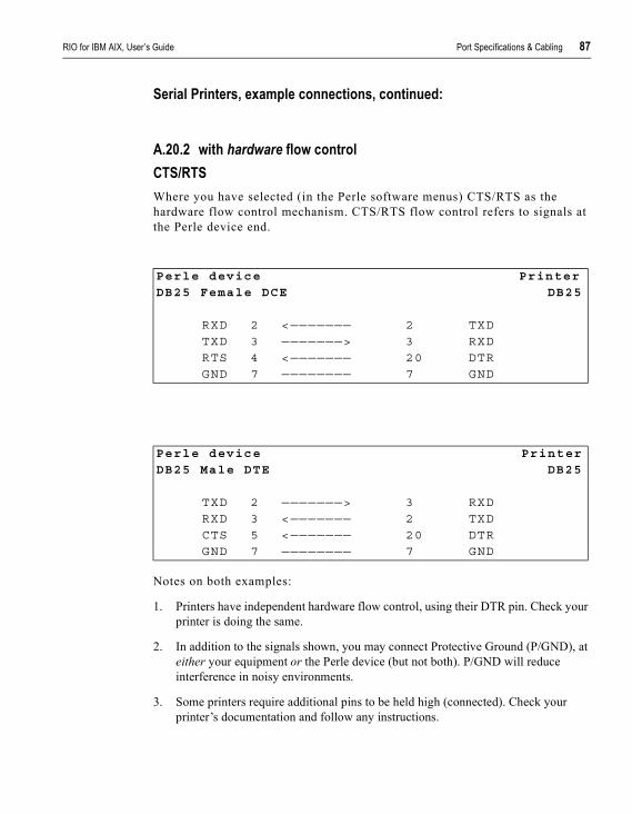
RIO for IBM AIX, User’s Guide Port Specifications & Cabling 87
Serial Printers, example connections, continued:
A.20.2 with hardware flow controlCTS/RTSWhere you have selected (in the Perle software menus) CTS/RTS as the hardware flow control mechanism. CTS/RTS flow control refers to signals at the Perle device end.
Notes on both examples:
1. Printers have independent hardware flow control, using their DTR pin. Check your printer is doing the same.
2. In addition to the signals shown, you may connect Protective Ground (P/GND), at either your equipment or the Perle device (but not both). P/GND will reduce interference in noisy environments.
3. Some printers require additional pins to be held high (connected). Check your printer’s documentation and follow any instructions.
Perle device Printer
DB25 Female DCE DB25
RXD 2 <——————— 2 TXDTXD 3 ———————> 3 RXDRTS 4 <——————— 20 DTRGND 7 ———————— 7 GND
Perle device Printer
DB25 Male DTE DB25
TXD 2 ———————> 3 RXDRXD 3 <——————— 2 TXDCTS 5 <——————— 20 DTRGND 7 ———————— 7 GND

88 Port Specifications & Cabling RIO for IBM AIX, User’s Guide
Serial Printers; example connections,
with hardware flow control
(continued)CTS/RTSWhere you have selected (in the Perle software menus) CTS/RTS as the hardware flow control mechanism. CTS/RTS flow control refers to signals at the Perle device end.
Notes:
1. the example for RJ45 connector shown above is for shielded ports only. If you have non-shielded RJ45 ports, use the pin-outs for the Perle device detailed in Section A.6.
2. the printer has independent hardware flow control, using its DTR pin. Check your printer is doing the same.
3. In addition to the signals shown in the examples above, you may connect Protective Ground (P/GND) if you have shielded twisted-pair (STP) cable. Connect P/GND at either your equipment or the Perle device (but not both). P/GND will reduce interference in noisy environments.
4. Some printers require additional pins to be held high (connected). Check your printer’s documentation and follow any instructions.
(shielded RJ45 ports only;- see note 1. below)
Perle device PrinterRJ45 DB25
RXD 6 <———————— 2 TXDTXD 5 ————————> 3 RXDRTS 8 <———————— 20 DTRS/GND 4 ————————— 7 S/GND
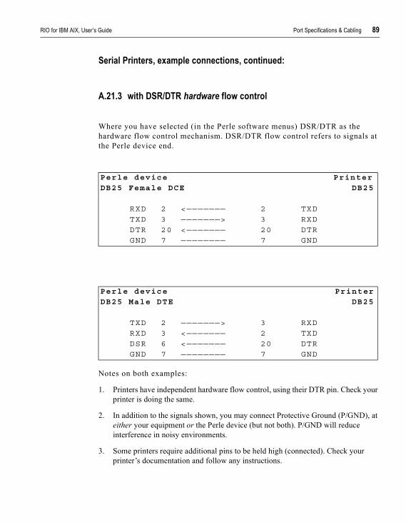
RIO for IBM AIX, User’s Guide Port Specifications & Cabling 89
Serial Printers, example connections, continued:
A.21.3 with DSR/DTR hardware flow control
Where you have selected (in the Perle software menus) DSR/DTR as the hardware flow control mechanism. DSR/DTR flow control refers to signals at the Perle device end.
Notes on both examples:
1. Printers have independent hardware flow control, using their DTR pin. Check your printer is doing the same.
2. In addition to the signals shown, you may connect Protective Ground (P/GND), at either your equipment or the Perle device (but not both). P/GND will reduce interference in noisy environments.
3. Some printers require additional pins to be held high (connected). Check your printer’s documentation and follow any instructions.
Perle device Printer
DB25 Female DCE DB25
RXD 2 <——————— 2 TXDTXD 3 ———————> 3 RXDDTR 20 <——————— 20 DTRGND 7 ———————— 7 GND
Perle device Printer
DB25 Male DTE DB25
TXD 2 ———————> 3 RXDRXD 3 <——————— 2 TXDDSR 6 <——————— 20 DTRGND 7 ———————— 7 GND
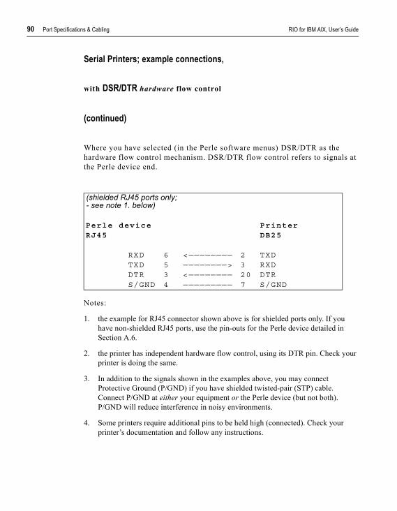
90 Port Specifications & Cabling RIO for IBM AIX, User’s Guide
Serial Printers; example connections,
with DSR/DTR hardware flow control
(continued)
Where you have selected (in the Perle software menus) DSR/DTR as the hardware flow control mechanism. DSR/DTR flow control refers to signals at the Perle device end.
Notes:
1. the example for RJ45 connector shown above is for shielded ports only. If you have non-shielded RJ45 ports, use the pin-outs for the Perle device detailed in Section A.6.
2. the printer has independent hardware flow control, using its DTR pin. Check your printer is doing the same.
3. In addition to the signals shown in the examples above, you may connect Protective Ground (P/GND) if you have shielded twisted-pair (STP) cable. Connect P/GND at either your equipment or the Perle device (but not both). P/GND will reduce interference in noisy environments.
4. Some printers require additional pins to be held high (connected). Check your printer’s documentation and follow any instructions.
(shielded RJ45 ports only;- see note 1. below)
Perle device PrinterRJ45 DB25
RXD 6 <———————— 2 TXDTXD 5 ————————> 3 RXDDTR 3 <———————— 20 DTRS/GND 4 ————————— 7 S/GND

RIO for IBM AIX, User’s Guide Port Specifications & Cabling 91
A.22 Structured Cabling Systems
This section details structured cabling systems. For direct (1:1) connections, go to Section A.7 Direct (1:1) Connections.
Notes:1. In the connection examples which follow, the signals shown refer to the connection
at the end of the cabling system to which your equipment is attached - see Figure 19. At the other end of the cabling system, where the Perle device is attached, we assume - and recommend - you use a straight-through RJ45 cable to connect our Perle device to the cabling system.
Figure 19 structured cabling system environment
92 Port Specifications & Cabling RIO for IBM AIX, User’s Guide
2. Within the structured cabling system, we presume you use straight-through cabling, i.e. pin 1 to pin 1, pin 2 to pin 2, etc.
3. Some user equipment need additional signals on the connector. These may not be supported by the Perle device, or your cable. The normal way to overcome this is to loopback - on the your equipment - one of the output lines to the required input. Refer to the documentation supplied with your equipment, or the supplier of the equipment, for information on which loop-backs, if any, are required.
4. At each end of the cable, you must terminate all pairs of wires on connector pins. An unconnected wire will receive electromagnetic radiation and possibly create interference in the cable.
5. If you have wiring other than shown in the connection examples, and DCD is an input on your equipment, ensure that it is not connected to DCD in the Perle device.
6. On the RJ45 connector, Protective Ground (P/GND) terminates on the connector and so does not have a pin number.
RIO for IBM AIX, User’s Guide Port Specifications & Cabling 93
A.23.1 Example Connections
In this section we show example connections between Perle ports and the following devices:
Terminals
structured cabling system Section A.24.2Terminal Connection using the modem device
Section A.25.3
Modems
structured cabling system Section A.26.4
PCs (DB9 connectors)
structured cabling system Section A.27.5
Serial Printers
structured cabling system Section A.28.6
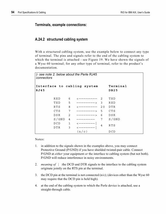
94 Port Specifications & Cabling RIO for IBM AIX, User’s Guide
Terminals, example connections:
A.24.2 structured cabling system
With a structured cabling system, use the example below to connect any type of terminal. The pins and signals refer to the end of the cabling system to which the terminal is attached - see Figure 19. We have shown the signals of a Wyse 60 terminal; for any other type of terminal, refer to the product’s documentation.
Notes:
1. in addition to the signals shown in the examples above, you may connect Protective Ground (P/GND) if you have shielded twisted-pair cable. Connect P/GND at either your equipment or the interface to cabling system (but not both). P/GND will reduce interference in noisy environments.
2. meaning of | :the DCD and DTR signals to the interface to the cabling system originate jointly on the RTS pin at the terminal.
3. the DCD pin at the terminal is not connected (n/c); (devices other than the Wyse 60 may require that the DCD pin is held high).
4. at the end of the cabling system to which the Perle device is attached, use a straight-through cable.
(- see note 2. below about the Perle RJ45 connectors
Interface to cabling system TerminalRJ45 DB25
RXD 6 <———————— 2 TXDTXD 5 ————————> 3 RXDRTS 8 <———————— 20 DTRCTS 7 ————————> 5 CTSDSR 2 ————————> 6 DSRS/GND 4 ———————— 7 S/GNDDCD 1 <———————|
4 RTSDTR 3 <———————|
(n/c) DCD
RIO for IBM AIX, User’s Guide Port Specifications & Cabling 95
5. the example for RJ45 connector shown above is for shielded RJ45 ports only. If you have non-shielded RJ45 ports, use the pin-outs for the Perle device detailed in Section A.6.
6. the minimum connection requirement is the RXD/TXD, TXD/RXD, RTS/RTS or DTR, CTS/CTS (if input flow control required) and S/GND signals (Interface to Cabling System/Terminal). The other pins may be connected (as in our example) to ensure minimum interference from unconnected pins.
7. for general advice on structured cabling systems, see Section A.22 Structured Cabling Systems.

96 Port Specifications & Cabling RIO for IBM AIX, User’s Guide
Terminal Connection using the modem device
example connections:
A.25.3 structured cabling system:
Notes:
1. in addition to the signals shown in the examples above, you may connect Protective Ground (P/GND) if you have shielded twisted-pair (STP) cable. Connect P/GND at either your equipment or the interface to the cabling system (but not both). P/GND will reduce interference in noisy environments.
2. the example for RJ45 connector shown above is for shielded RJ45 ports only. If you have a non-shielded RJ45 ports, use the pin-outs for the Perle device detailed in Section A.6.
3. the above example assumes that DTR on the terminal is being used for hardware flow control. If you are using RTS on the terminal as the hardware flow control pin, connect DTR on the Terminal to DCD and DTR on the interface to the cabling system, and connect RTS on the terminal to RTS on the interface to the cabling system.
4. meaning of | the DCD and DTR signals at the interface to the cabling system originate jointly on the RTS pin at the terminal.
(- see note 2. below about the Perle RJ45 connectors
Interface to cabling system TerminalRJ45 DB25
RXD 6 <———————— 2 TXDTXD 5 ————————> 3 RXDRTS 8 <———————— 20 DTRCTS 7 ————————> 5 CTSDSR 2 ————————> 6 DSRS/GND 4 ———————— 7 S/GNDDCD 1 <———————|
4 RTSDTR 3 <———————|
(n/c) DCD

RIO for IBM AIX, User’s Guide Port Specifications & Cabling 97
5. the minimum connection requirement is the RXD/TXD, TXD/RXD, RTS/DTR, S/GND and DCD-DTR/RTS signals (Interface to Cabling System/Terminal). The other pins may be connected (as in our example) to ensure minimum interference from unconnected pins.
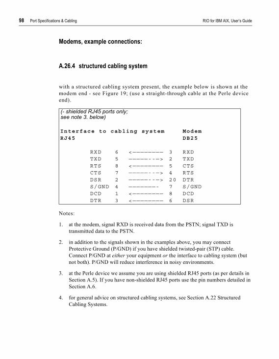
98 Port Specifications & Cabling RIO for IBM AIX, User’s Guide
Modems, example connections:
A.26.4 structured cabling system
with a structured cabling system present, the example below is shown at the modem end - see Figure 19; (use a straight-through cable at the Perle device end).
Notes:
1. at the modem, signal RXD is received data from the PSTN; signal TXD is transmitted data to the PSTN.
2. in addition to the signals shown in the examples above, you may connect Protective Ground (P/GND) if you have shielded twisted-pair (STP) cable. Connect P/GND at either your equipment or the interface to cabling system (but not both). P/GND will reduce interference in noisy environments.
3. at the Perle device we assume you are using shielded RJ45 ports (as per details in Section A.5). If you have non-shielded RJ45 ports use the pin numbers detailed in Section A.6.
4. for general advice on structured cabling systems, see Section A.22 Structured Cabling Systems.
(- shielded RJ45 ports only; see note 3. below)
Interface to cabling system ModemRJ45 DB25
RXD 6 <———————— 3 RXDTXD 5 —————--—> 2 TXDRTS 8 <———————— 5 CTSCTS 7 —————--—> 4 RTSDSR 2 —————--—> 20 DTRS/GND 4 ———————- 7 S/GNDDCD 1 <———————— 8 DCDDTR 3 <———————— 6 DSR
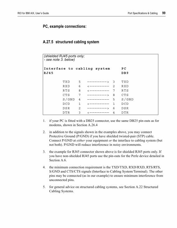
RIO for IBM AIX, User’s Guide Port Specifications & Cabling 99
PC, example connections:
A.27.5 structured cabling system
1. if your PC is fitted with a DB25 connector, use the same DB25 pin-outs as for modems, shown in Section A.26.4
2. in addition to the signals shown in the examples above, you may connect Protective Ground (P/GND) if you have shielded twisted-pair (STP) cable. Connect P/GND at either your equipment or the interface to cabling system (but not both). P/GND will reduce interference in noisy environments.
3. the example for RJ45 connector shown above is for shielded RJ45 ports only. If you have non-shielded RJ45 ports use the pin-outs for the Perle device detailed in Section A.6.
4. the minimum connection requirement is the TXD/TXD, RXD/RXD, RTS/RTS, S/GND and CTS/CTS signals (Interface to Cabling System/Terminal). The other pins may be connected (as in our example) to ensure minimum interference from unconnected pins.
5. for general advice on structured cabling systems, see Section A.22 Structured Cabling Systems.
(shielded RJ45 ports only;- see note 3. below)
Interface to cabling system PCRJ45 DB9
TXD 5 ————————> 3 TXDRXD 6 <———————— 2 RXDRTS 8 <———————— 7 RTSCTS 7 ————————> 8 CTSS/GND 4 ————————— 5 S/GNDDCD 1 <———————— 1 DCDDSR 2 ————————> 6 DSRDTR 3 <———————— 4 DTR
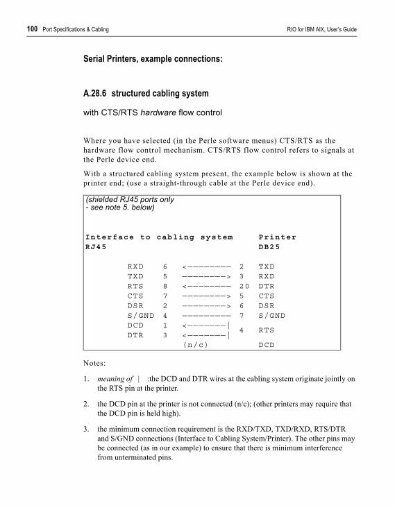
100 Port Specifications & Cabling RIO for IBM AIX, User’s Guide
Serial Printers, example connections:
A.28.6 structured cabling system
with CTS/RTS hardware flow control
Where you have selected (in the Perle software menus) CTS/RTS as the hardware flow control mechanism. CTS/RTS flow control refers to signals at the Perle device end.
With a structured cabling system present, the example below is shown at the printer end; (use a straight-through cable at the Perle device end).
Notes:
1. meaning of | :the DCD and DTR wires at the cabling system originate jointly on the RTS pin at the printer.
2. the DCD pin at the printer is not connected (n/c); (other printers may require that the DCD pin is held high).
3. the minimum connection requirement is the RXD/TXD, TXD/RXD, RTS/DTR and S/GND connections (Interface to Cabling System/Printer). The other pins may be connected (as in our example) to ensure that there is minimum interference from unterminated pins.
(shielded RJ45 ports only - see note 5. below)
Interface to cabling system PrinterRJ45 DB25
RXD 6 <———————— 2 TXDTXD 5 ————————> 3 RXDRTS 8 <———————— 20 DTRCTS 7 ————————> 5 CTSDSR 2 ————————> 6 DSRS/GND 4 ————————— 7 S/GNDDCD 1 <———————|
4 RTSDTR 3 <———————|
(n/c) DCD

RIO for IBM AIX, User’s Guide Port Specifications & Cabling 101
4. in addition to the signals shown in the examples above, you may connect Protective Ground (P/GND) if you have shielded twisted-pair (STP) cable. Connect P/GND at either your equipment or the interface to cabling system (but not both). P/GND will reduce interference in noisy environments.
5. the example for RJ45 connector shown above is for shielded RJ45 ports only. If you have non-shielded RJ45 ports use the pin-outs for the Perle device detailed in Section A.6.
6. the printer is using its DTR pin for hardware flow control. Check your printer is doing the same.
7. for general advice on structured cabling systems, see Section A.22

102 Port Specifications & Cabling RIO for IBM AIX, User’s Guide
Serial Printers; example connections,
A.29.7 structured cabling system
with DSR/DTR hardware flow control
Where you have selected (in the Perle software menus) DSR/DTR as the hardware flow control mechanism. DSR/DTR flow control refers to signals at the Perle device end.
Notes:
1. the example for RJ45 connector shown above is for shielded ports only. If you have non-shielded RJ45 ports, use the pin-outs for the Perle device detailed in Section A.6.
2. the printer is using its DTR pin for hardware flow control. Check your printer is doing the same.
3. In addition to the signals shown in the examples above, you may connect Protective Ground (P/GND) if you have shielded twisted-pair (STP) cable. Connect P/GND at either your equipment or the Perle device (but not both). P/GND will reduce interference in noisy environments.
(shielded RJ45 ports only - see note 1. below)
Interface to cabling system PrinterRJ45 DB25
RXD 6 <———————— 2 TXDTXD 5 ————————> 3 RXDDTR 3 <———————— 20 DTRCTS 7 ————————> 5 CTSDSR 2 ————————> 6 DSRS/GND 4 ————————— 7 S/GNDDCD 1 <———————|
4 RTSRTS 8 <———————|
(n/c) DCD
RIO for IBM AIX, User’s Guide Port Specifications & Cabling 103
4. the minimum connection requirement is the RXD/TXD, TXD/RXD, DTR/DTR and S/GND connections (Interface to Cabling System/Printer). The other pins may be connected (as in our example) to ensure that there is minimum interference from unterminated pins.
5. Some printers require additional pins to be held high (connected). Check your printer’s documentation and follow any instructions.
6. meaning of | :the DCD and RTS wires at the cabling system originate jointly on the RTS pin at the printer.
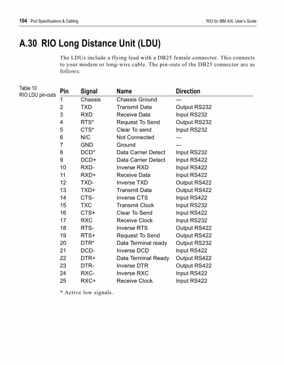
104 Port Specifications & Cabling RIO for IBM AIX, User’s Guide
A.30 RIO Long Distance Unit (LDU)The LDUs include a flying lead with a DB25 female connector. This connects to your modem or long-wire cable. The pin-outs of the DB25 connector are as follows:
Table 10RIO LDU pin-outs
* Active low signals.
Pin Signal Name Direction1 Chassis Chassis Ground —2 TXD Transmit Data Output RS2323 RXD Receive Data Input RS2324 RTS* Request To Send Output RS2325 CTS* Clear To send Input RS2326 N/C Not Connected —7 GND Ground —8 DCD* Data Carrier Detect Input RS2329 DCD+ Data Carrier Detect Input RS42210 RXD- Inverse RXD Input RS42211 RXD+ Receive Data Input RS42212 TXD- Inverse TXD Output RS42213 TXD+ Transmit Data Output RS42214 CTS- Inverse CTS Input RS42215 TXC Transmit Clock Input RS23216 CTS+ Clear To Send Input RS42217 RXC Receive Clock Input RS23218 RTS- Inverse RTS Output RS42219 RTS+ Request To Send Output RS42220 DTR* Data Terminal ready Output RS23221 DCD- Inverse DCD Input RS42222 DTR+ Data Terminal Ready Output RS42223 DTR- Inverse DTR Output RS42224 RXC- Inverse RXC Input RS42225 RXC+ Receive Clock Input RS422
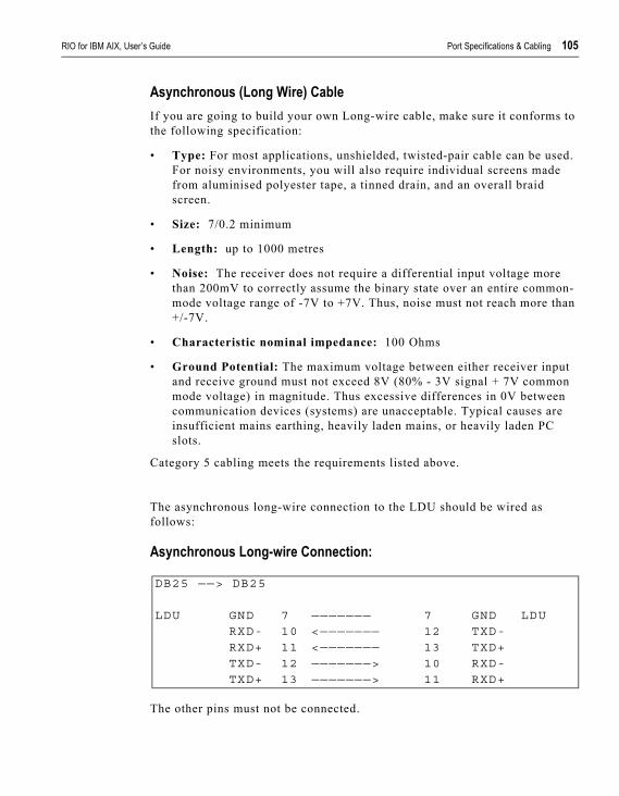
RIO for IBM AIX, User’s Guide Port Specifications & Cabling 105
Asynchronous (Long Wire) CableIf you are going to build your own Long-wire cable, make sure it conforms to the following specification:
• Type: For most applications, unshielded, twisted-pair cable can be used. For noisy environments, you will also require individual screens made from aluminised polyester tape, a tinned drain, and an overall braid screen.
• Size: 7/0.2 minimum
• Length: up to 1000 metres
• Noise: The receiver does not require a differential input voltage more than 200mV to correctly assume the binary state over an entire common-mode voltage range of -7V to +7V. Thus, noise must not reach more than +/-7V.
• Characteristic nominal impedance: 100 Ohms
• Ground Potential: The maximum voltage between either receiver input and receive ground must not exceed 8V (80% - 3V signal + 7V common mode voltage) in magnitude. Thus excessive differences in 0V between communication devices (systems) are unacceptable. Typical causes are insufficient mains earthing, heavily laden mains, or heavily laden PC slots.
Category 5 cabling meets the requirements listed above.
The asynchronous long-wire connection to the LDU should be wired as follows:
Asynchronous Long-wire Connection:
The other pins must not be connected.
DB25 ——> DB25
LDU GND 7 ——————— 7 GND LDURXD- 10 <——————— 12 TXD-RXD+ 11 <——————— 13 TXD+
TXD- 12 ———————> 10 RXD-TXD+ 13 ———————> 11 RXD+
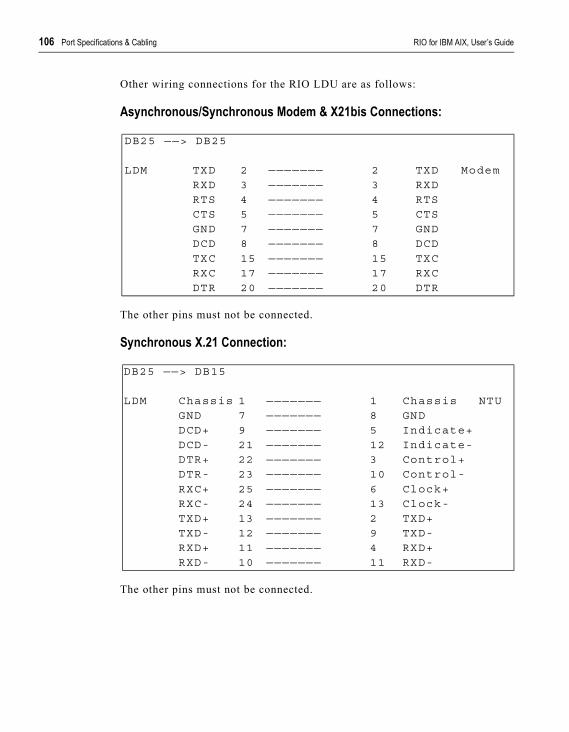
106 Port Specifications & Cabling RIO for IBM AIX, User’s Guide
Other wiring connections for the RIO LDU are as follows:
Asynchronous/Synchronous Modem & X21bis Connections:
The other pins must not be connected.
Synchronous X.21 Connection:
The other pins must not be connected.
DB25 ——> DB25
LDM TXD 2 ——————— 2 TXD ModemRXD 3 ——————— 3 RXDRTS 4 ——————— 4 RTSCTS 5 ——————— 5 CTSGND 7 ——————— 7 GNDDCD 8 ——————— 8 DCD
TXC 15 ——————— 15 TXCRXC 17 ——————— 17 RXCDTR 20 ——————— 20 DTR
DB25 ——> DB15
LDM Chassis 1 ——————— 1 Chassis NTUGND 7 ——————— 8 GNDDCD+ 9 ——————— 5 Indicate+DCD- 21 ——————— 12 Indicate-DTR+ 22 ——————— 3 Control+DTR- 23 ——————— 10 Control-
RXC+ 25 ——————— 6 Clock+RXC- 24 ——————— 13 Clock-TXD+ 13 ——————— 2 TXD+TXD- 12 ——————— 9 TXD-RXD+ 11 ——————— 4 RXD+RXD- 10 ——————— 11 RXD-
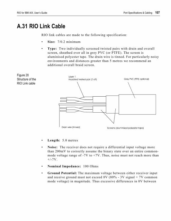
RIO for IBM AIX, User’s Guide Port Specifications & Cabling 107
A.31 RIO Link CableRIO link cables are made to the following specification:
• Size: 7/0.2 minimum
• Type: Two individually screened twisted pairs with drain and overall screen, sheathed over all in grey PVC (or PTFE). The screen is aluminised polyester tape. The drain wire is tinned. For particularly noisy environments and distances greater than 5 metres we recommend an additional overall braid screen.
Figure 20Structure of the RIO Link cable
• Length: 5.0 metres
• Noise: The receiver does not require a differential input voltage more than 200mV to correctly assume the binary state over an entire common-mode voltage range of -7V to +7V. Thus, noise must not reach more than +/-7V.
• Nominal Impedance: 100 Ohms
• Ground Potential: The maximum voltage between either receiver input and receive ground must not exceed 8V (80% - 3V signal + 7V common mode voltage) in magnitude. Thus excessive differences in 0V between
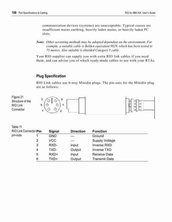
108 Port Specifications & Cabling RIO for IBM AIX, User’s Guide
communication devices (systems) are unacceptable. Typical causes are insufficient mains earthing, heavily laden mains, or heavily laden PC slots.
Note: Other screening methods may be adopted dependent on the environment. For example, a suitable cable is Belden equivalent 9829, which has been tested to 75 metres. Also suitable is shielded Category 5 cable.
Your RIO supplier can supply you with extra RIO link cables if you need them, and can advise you of which ready-made cables to use with your RTAs.
Plug SpecificationRIO Link cables use 6-way Minidin plugs. The pin-outs for the Minidin plug are as follows:
Figure 21Structure of the RIO Link Connector
Table 11RIO Link Connector pin-outs
Pin Signal Direction Function1 GND — Ground2 VCC — Supply Voltage3 RXD- Input Inverse RXD4 TXD- Output Inverse TXD5 RXD+ Input Receive Data6 TXD+ Output Transmit Data
RIO for IBM AIX, User’s Guide Port Specifications & Cabling 109
The cable should be wired as follows:
Wires 3 and 4, and 5 and 6, must be twisted together. For high noise and/or ground potential differences we recommend the Fibre-optic module.
Minidin GND 1 Not Connected 1 GND MinidinVCC 2 Not Connected 2 VCCRXD- 3 ——————— 4 TXD-TXD- 4 ——————— 3 RXD-RXD+ 5 ——————— 6 TXD+
TXD+ 6 ——————— 5 RXD+

110 Port Specifications & Cabling RIO for IBM AIX, User’s Guide
A.32 Fibre Optic CableFibre-optic cable must conform to the following specification:
• Fibre Type: 62.5µm/125µm multimode silica graded index fibre (=62.5µm core diameter, 125µm cladding inside 250µm buffer).
• Cable Type: Tight buffered/jacketed.
• Fibres: Duplex, 4 core, etc., as required by installation (2 fibres are used by each Perle fibre-optic link). Each core sub-jacketed, individually coloured.
• Connectors: ST-type connector.
• Strength Member: Aramid (e.g. Kevlar) strength suitable for installation procedure.
• Numerical Aperture: 0.27 - 0.3 (0.275 will be typical of most fibres).
• Attenuation: Max 6db/km @ 820nm (4db will be typical of most fibres).
Cable JacketingLow Smoke Zero Halogen (LSOH) cable should be used in situations where smoke from burning cables could concentrate in a public area.
Steel wire armouring, steel wire braid or corrugated tube cable will be required for underground installation of fibre (by direct burial).
Cable with a metal (aluminium) foil layer and a petroleum jelly moisture barrier will be required where the cable is going to be exposed to moisture.
Non-metallic, self-supporting cable will be required for aerial (pole) applications.
Normal indoor cable requires installation in conduit or cable trays. In other situations, crush-resistant cables may be required to withstand handling and environment. In all situations, cable handling should not exceed the specifications laid down by the cable manufacturer.
Installation AdviceInstallation temperature range, minimum bending radius and maximum installation tension must all be strictly adhered to. The most suitable method for pulling through a fibre-optic cable is with a tool made specifically for this purpose. Cable must not be allowed to kink or twist and must not be pulled over sharp edges in ducts or cable trays.
RIO for IBM AIX, User’s Guide Port Specifications & Cabling 111
Wherever possible, you are strongly advised to splice pre-terminated pigtails on site. This will ensure the greatest possible reliability and performance. Such pigtails are readily available ex-stock from a number of distributors and will have been terminated in clean conditions unlikely to be encountered when terminating on site. In practice, productivity and reliability of installation is increased by splicing rather than direct application of connectors on site. The most suitable tool for splicing is a fusion splicer.
You can choose to have one or more redundant, terminated fibres in a link. You can also choose to use a fibre with more cores than necessary. Where a RIO fibre-optic link requires only duplex cable, four-core may be installed instead
Installation may be easier if the cable is divided into two smaller lengths, pulled through separately and spliced at a suitable midpoint. The join should be made in a suitable splice enclosure or box to enable maintenance.
You are advised to terminate each end of the main fibre in a distribution enclosure, with an excess length of cable coiled and secured in the enclosure at each end. Connection from the enclosure to the equipment should then be made with a patch lead. This patch lead can be easily replaced if it becomes damaged, and can be moved to reconfigure the system or swap over to a redundant link. You are advised to use the same ST-type connector throughout your system.
Fibre communication distance is rated at one kilometre maximum.

112 Port Specifications & Cabling RIO for IBM AIX, User’s Guide
A.33 Parallel DB25 PortThis port provides a Centronics-type interface for Parallel printers. Parallel cables use a straight 25-way connection.
Table 12Parallel pin-outs
* = Active low
Pin Circuit Direction Function1 STROBEN* Output PSTROBE2 D0 Output DATA 13 D1 Output DATA 24 D2 Output DATA 35 D3 Output DATA 46 D4 Output DATA 57 D5 Output DATA 68 D6 Output DATA 79 D7 Output DATA 810 PACKN* Input ACK11 PBUSY Input BUSY12 PPE Input PE13 PSLCT Input SLCT14 AUTOFDXT* Output AUTOFEED15 PERRORN* Input FAULT16 PINITN* Output INPUT PRIME17 PSLINN* Output SLCT IN18 GND — GROUND19 GND — GROUND20 GND — GROUND21 GND — GROUND22 GND — GROUND23 GND — GROUND24 GND — GROUND25 GND — GROUND
RIO for IBM AIX, User’s Guide Port Specifications & Cabling 113
A.34 RS232 RJ45 Opto-isolated PortsThese ports have the RXD+ and RXD- pins electrically isolated from the rest of the unit using opto-isolators. This provides two advantages: the signal will not pick up interference, and power surges or sparks caused by voltage changes will not be transmitted.
Further noise reductions can be achieved by using software flow control. The pin-outs for these ports are as follows:
Table 13RS232 RJ45 Opto-isolated pin-outs
Pin 6 (Ground) should be used as TXD+; pin 7 (CTS) should be connected to pin 2 (RTS-) on the peripheral device.
The pins in the RJ45 socket are located at the top, with pin 1 on the left (see Figure 18).
Pin Signal Direction Function1 Chassis — Chassis Ground2 RTS- Output Inverse RTS3 TXD- Output Inverse TXD4 RXD+ Input Receive Data5 RXD- Input Inverse RXD6 Ground — Signal Ground7 CTS Input Clear To Send8 Chassis — Chassis Ground
114 Port Specifications & Cabling RIO for IBM AIX, User’s Guide
A.35 RS422 DB25 PortsThese ports provide a full RS422 interface for serial devices. When wiring with RS422 ports refer to the documentation supplied with the device, or the suppliers of the device, for wiring instructions.
RS422 twisted-pair cable allows you to run a serial device at 115.2Kb up to 1km from the Perle device port.
The RS422 D25 pin descriptions are:
Table 14RS422 DB25 pin-outs
The two wires (+ and -) for each signal must be twisted together to form a pair.
The names of some of these signals are often used in reverse. Here, CTS and DTR are outputs, RTS and DSR are inputs.
Pin Circuit Direction Function1 Chassis Connects to case2 RXD+ Input Receive Data3 TXD+ Output Transmit Data4 RTS+ Input Receive Hardware Flow
Control5 CTS+ Output Transmit Hardware Flow
Control6 DTR+ Output Data Terminal Ready7 Ground — Connects to logic 0V8 DSR+ Input Data Set Ready10 DSR- Input Inverse DSR13 CTS- Output Inverse CTS14 RXD- Input Inverse RXD16 TXD- Output Inverse TXD18 DTR- Output Inverse DTR19 RTS- Input Inverse RTS20 DCD+ Input Data Carrier Detect21 RI- Input Inverse RI22 RI+ Input Ring Indicator23 DCD- Input Inverse DCD

RIO for AIX User’s Guide Technical Support 115
A p p e n d i x B
Technical Support
Troubleshooting.
Symptoms Diagnosis SolutionWarning displayed on console during bootup:Host card ‘defined'but not’available'.
Hardware clash—the memory address or interrupt selected for the host card is already being used by another device.
To pinpoint the clash, enter the command smit lsattr . This displays the List Devices menu. The ‘Show Characteristics of a Defined Device’ option enables you to display the configuration of devices installed in your machine, including interrupt and memory address. Check the configuration of your RIO card against the other hardware devices (particularly networking cards, SCSI controllers, & VGA cards). When you locate the clash, reconfigure your host card.
After rebooting, RIO ttys are ’defined' but not ’available'.
The driver was unable to configure the TTY
Checka) all the RTAs are connectedb) the host card is seated correctlyc) the wiring
Message:prerequisitefailure while de-installing the riosoftware
You still have RIO devices available or defined
Remove all RIO devices via SMIT.
Error: piocustp:<rio>not a valid adapter
You have selected an incorrect print queue for transparent printing
Go to the SMIT menu option ’Add a print queue'. Select Attachment Type ‘local - printer attached to local host'.

116 Technical Support RIO for AIX User’s Guide
Warning:device busy
You are trying to reconfigure/delete a device whilst the device is open (enabled)
Ensure there is no login running on the port (either through Enable Login or through User Login via the keyboard).For a printer (lp0 or xp0), ensure no print job is running.
Warning:device tty n hasconfiguredchildren (where n is the device number)
You have a transparent print connection enabled on the device. You may be trying to reconfigure/delete the TTY device.
Delete the transparent printer (the child).
Warning:memory addressmight be incorrect
On the ISA host card, you may have selected an incorrect memory address
Try the next memory address on the rotary switches and reboot.
There is no communication between an RTA and its host card when the RTA is showing as ’available'.
You may have changed the links between the RTA and the host card while your machine was off or rebooting.
reboot the RTA by disconnecting and re-connecting the cable to it.Avoid changes to your system while the host card cannot communicate with its RTAs.
You are unable to boot an RTA
There may be a problem with the connector and /or cable
Try another cable.
Warning:RTA has configuredchildren
You are trying to delete an RTA while the RTA has a tty or printer still defined.
Ensure the RTA has no TTY or printer (child) devices.
Warning:another adapteraddress/interruptconflicts with thisone
You have selected an interrupt level on the ISA host card which clashes with another device.
Try another interrupt level.
Message:’There are no itemsof this type' whenusing the option’Add an RTA'.
The RTA is not responding.
Ensure the RTA is connected to the host card. Power-cycle the RTA manually.
Symptoms Diagnosis Solution

RIO for AIX User’s Guide Technical Support 117
Inconsistent LED pattern on an RTA:on an 8-port RTA, one or other of the LEDs next to ports 1 and 5 not lit;.on a 16-port RTA, one or other of the RUN and CON LEDs is not lit.
The RTA is not responding.
Power-cycle the RTA manually.
Symptoms Diagnosis Solution

118 Technical Support RIO for AIX User’s Guide
Making a technical support queryThis section contains the following information about making a query;
• <hypertext>Who to contact on page <hypertext>118
• <hypertext>Information needed when making a query on page <hypertext>119
• <hypertext>Making a support query via the Perle web page on page <hypertext>120
Who to contactIf you bought your product from a registered Perle supplier, you must contact their Technical Support department; they are qualified to deal with your problem.
If you are a registered Perle supplier, and bought your product from Perle, contact Perle Technical Support at the offices listed below.
RIO for AIX User’s Guide Technical Support 119
Information needed when making a queryWhen you make a technical support enquiry please have the following information ready;
HintPrint out this page and fill in the table provided with the basic information you need.
Item Write details here
Product name and version
Problem description
Operating system versionDriver versionDetails of any other cards installed in your system
Your nameCompany NameCountryPhone numberFax numberEmail address (if available)

120 Technical Support RIO for AIX User’s Guide
Making a support query via the Perle web pageIf you have an internet connection, please send details of your problem to Technical Support using the email links provided on the Perle web site in the ‘Support’ area.
See also <hypertext>Perle support centres worldwide on page <hypertext>123 for email links and other contact details for the Perle technical support centres.
Click here to access our website at the following URL:http://www.perle.com

RIO for AIX User’s Guide Technical Support 121
Repair procedureBefore sending a unit for repair, you must contact your Perle supplier. If, however, you bought your product directly from Perle you can contact directly. See <hypertext>Perle support centres worldwide on page <hypertext>123 for contact information.
Customers who are In Europe, Africa or Middle East can submit repair details via a website form shown in the next picture. This form is on the Perle website, www.perle.com, in the Support area.
In the USA and Asia contact the office shown in the Technical Support section.
Website RMA (Return Material Authorisation) Form
Click here to access our web site at the following URL:http://www.perle.com/support/rma_form.html

122 Technical Support RIO for AIX User’s Guide
Feedback about this manualIf you have any comments or suggestions for improving this manual please email Perle using the following address;
Please include the title, part number and date of the manual (you can find these on the title page at the front of this manual).

RIO for AIX User’s Guide Technical Support 123
Perle support centres worldwideNotePerle offers free technical support to Perle Authorised Distributors and Registered Perle Resellers. To access technical support please visit the Perle website at www.perle.com/support.If you are unable to find the information you require, please feel free to contact our technical support teams by email using the addresses shown in the next table.
Country Address EmailNorth America Perle Systems Ltd.
60 Renfrew DriveMarkhamOntarioCanadaL3R OE1
Email: [email protected]
Europe Perle Systems Europe Ltd. 3 Wintersells Road Byfleet SurreyKT14 7LFUK
Email: [email protected]
Asia Perle Asia Pacific (Pte) Ltd.Yu Li Industrial BuildingNo 37 Lor 23 Sims Avenue04-01/05Singapore 388371
Email: [email protected]
Worldwide Perle Systems Ltd.60 Renfrew DriveMarkhamOntarioCanadaL3R OE1
Email: [email protected]

124 Technical Support RIO for AIX User’s Guide
RIO for IBM AIX User’sGuide Index cxxv
Index
AAdding a Host Card, 56Adding a host card, 56Adding a New RTA, 51Adding a Print Queue, 36Adding a Printer, 33Adding an RTA, 51Adopting an RTA, 54Asynchronous (Long Wire Cable),
to use with RIO LDU, 105
Bbos.printers.rte, 5bos.terminfo.rte, 5
CCable specifications, 61–114Cabling Options, 13Centronics interface, see Ports, parallelCharacter Bits, 30Checklist, 3Connectors, see Portscontacting Perle Systems
for technical support, 118
DDeleting a Host Card, 56Deleting a host card, 56Deleting an RTA, 53Device Driver, Installing, 5Device Driver, Removing, 6Direct (1 to 1) connection
definition and advice, 69Draw RTA Topology, 48Dual Host Failsafe, 2, 39Dual Host Failsafe, Definition, 39Dual Host Failsafe, Installing a Master/Slave
System, 40Dual Host Failsafe, Master/Slave Mode, 40Dual Host Failsafe, Shared Mode, 40
FFailsafe links, 50Fault Tolerant Cabling, 2Fault Tolerant Links, 14Fault Tolerant Links, Adding, 50Fibre Optic Link Kit (FOLK), 2, 3, 21Fibre Optic Link Kit (FOLK), Features, 21Fibre Optic Link Kit (FOLK), Installation, 21Fibre-optic cable
installation, 110specification, 110
HHost card
Adding, 56Deleting, 56Installation, 7–11Removing, 56
Host Cards, Adding, 56Host Cards, Deleting, 56Host Cards, Display Configuration, 57Host Cards, Removing, 56Host Interconnections, 42, 44
IIdentify an RTA, 55Installation
Fault Tolerant Links, 21Host card, 7–11
cxxvi Index User’s Guide
RTAs, 13–26Installation checklist, 3Installation overview, 2Installing RTAs, 13installp, 5ISA Host Card, Configuration, 7, 9ISA Host Card, Installation, 7, 9ISA Host Card, Interrupts, 9ISA Host Card, Memory Address, 7, 8
LLEDs, 16, 20Link
Installation, 21Link Failure, 51Link failure, 51Links, see RIO link cablesLoad RIO Device Configuration, 42, 59Login Devices, 28Login Types, 30Long Distance Module (LDM), 2, 3, 22Long Distance Module (LDM), Installation, 22Long Distance Module (LDM), Long Distance
Unit (LDU), 23Long Distance Module (LDM), Long-wire
Connections, 24Long Distance Module (LDM), Modem
Connections, 24Long Distance Module (LDM), Performance, 22Long Distance Unit (LDU), 23
Pinouts, cabling, 104–105Long Distance Unit (LDU), Features, 24Long Distance Unit (LDU), Rotary Switch
Settings, 25
MMaster/Slave Dual Host Failsafe, Definition, 40Master/Slave Dual Host Failsafe, Installation, 41Micro Channel Host Card, Features, 11Micro Channel Host Card, Installation, 10Modems
example connectionsdirect (1 to 1) connections, 81–82
structured cabling system, 98Modems, Line Speed Negotiation, 26Move
RTA, 53Moving an RTA, 53
OOptimum configuration, 14Opto-isolated ports, see RS232 RJ45 portsOverview, Installation, 2Overview, Product, 1
PParallel Printing, 33Parity, 30PCI Host Card, Features, 10PCI Host Card, Installation, 9PCs
example connectionsdirect (1 to 1) connections, 83–84structured cabling systems, 99
Pin-outs, see Ports, specifications/typesPorts
DB25, see RS232 DB25DB25, see RS422 DB25parallel, 112RJ45, see RS232 RJ45specifications/types, 61–114
Print Devices, Enabling, 33Print Queue, Adding, 36Print Queues, Reconfiguring, 37Printers
parallel, see Ports, parallelserial, see Serial Printers
Printers, Adding, 33product repair form, 121
RReconfiguring a Print Queue, 37Remote terminal adaptors
Installation, 13–26Maximum number, 14
User’s Guide Index cxxvii
Move, 53Optimum configuration, 14
Remove RIO Devices, 59Removing a Host Card, 56Removing an RTA, 52repair procedure, 121
product repair form, 121RMA form, 121
RIO Link cables, 107Disconnection, 51Failsafe links, 50Failure, 51Installation, 18, 51
RMA form, 121Rotary Switches, Location of, 8RS232 DB25
ports female (DCE), 63ports male (DTE), 64
RS232 RJ45ports, non-shielded, 68ports, opto-isolated, 113ports, shielded, 66
RS232* (asterisk) DB25ports, 65
RS422 DB25
ports, 114RTA Name, 28RTA Topology, 48RTA, Port Numbering, 16RTA16, Boot LED States, 20RTA16, Installation, 20RTA8, Boot LED States, 18RTA8, Installation, 18RTA8, Wall Mounting, 19RTAs, Adding, 51RTAs, Adopting, 54RTAs, Configuring, 27RTAS, Defining, 27RTAs, Deleting, 53RTAs, Diagnostic LEDs, 16RTAs, Features, 15RTAs, Identifying, 55RTAs, Installation Tips, 13RTAs, Link Sockets, 16RTAS, Maximum No., 51RTAs, Maximum No., 13RTAs, Moving, 53RTAs, Optimum Configuration, 14RTAs, Rebooting, 55RTAs, Removing, 52RTAs,see Remote Terminal Adaptors
SSave RIO Device Configuration, 42, 59Serial printers,
example connections,direct (1 to 1) connections, 85–90structured cabling system, 100–103
Serial Printing, 33Shared Dual Host Failsafe, Definition, 40Shared Dual Host Failsafe, Host Failure, 45Shared Dual Host Failsafe, Installation, 44Software Installation, 5Status of device at boot time, 30Stop Bits, 30Structured Cabling Systems

cxxviii Index User’s Guide
advice, 91–92STTY Attributes, for Login, 31STTY Attributes, for RUN Time, 30System Management, 47
Ttechnical support, 118
centres worldwide, 123queries, information needed for, 119via the internet, 120who to contact, 118
Terminal Type, 30Terminals
example connectionsdirect (1 to 1) connections, 71–75structured cabling system, 94
Terminals, using the modem deviceexample connections
direct (1 to 1) connections, 76–80
structured cabling system, 96–97Transparent Printing, 33Troubleshooting, 115–117TTY Numbers, 32TTY, Baud Rate, 30TTY, Port Number, 28
WWall Mounting, 19Wall-mounting, 19Wiring, see Cable Specifications
XX.21 Synchronous
example connection with LDU, 106X.21bis, example connection
with LDU, 106