risk assessment and update of inspection procedures for
TRANSCRIPT

Risk Assessment and Update of Inspection Procedures for Culverts
Russ College of Engineering and Technology
Ohio Research Institute for Transportation and the Environment
Prepared in cooperation with the Ohio Department of Transportation and the U.S. Department Transportation,
Federal Highway Administration
Final ReportFebruary 2005

i
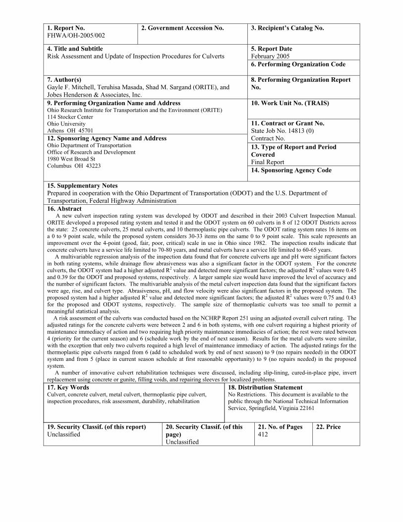
1. Report No. FHWA/OH-2005/002
2. Government Accession No. 3. Recipient’s Catalog No.
5. Report Date February 2005
4. Title and Subtitle Risk Assessment and Update of Inspection Procedures for Culverts
6. Performing Organization Code
7. Author(s) Gayle F. Mitchell, Teruhisa Masada, Shad M. Sargand (ORITE), and Jobes Henderson & Associates, Inc.
8. Performing Organization Report No.
10. Work Unit No. (TRAIS) 9. Performing Organization Name and Address Ohio Research Institute for Transportation and the Environment (ORITE) 114 Stocker Center Ohio University Athens OH 45701
11. Contract or Grant No. State Job No. 14813 (0) Contract No. 13. Type of Report and Period CoveredFinal Report
12. Sponsoring Agency Name and Address Ohio Department of Transportation Office of Research and Development 1980 West Broad St Columbus OH 43223
14. Sponsoring Agency Code
15. Supplementary Notes Prepared in cooperation with the Ohio Department of Transportation (ODOT) and the U.S. Department of Transportation, Federal Highway Administration 16. Abstract A new culvert inspection rating system was developed by ODOT and described in their 2003 Culvert Inspection Manual. ORITE developed a proposed rating system and tested it and the ODOT system on 60 culverts in 8 of 12 ODOT Districts across the state: 25 concrete culverts, 25 metal culverts, and 10 thermoplastic pipe culverts. The ODOT rating system rates 16 items on a 0 to 9 point scale, while the proposed system considers 30-33 items on the same 0 to 9 point scale. This scale represents animprovement over the 4-point (good, fair, poor, critical) scale in use in Ohio since 1982. The inspection results indicate thatconcrete culverts have a service life limited to 70-80 years, and metal culverts have a service life limited to 60-65 years. A multivariable regression analysis of the inspection data found that for concrete culverts age and pH were significant factors in both rating systems, while drainage flow abrasiveness was also a significant factor in the ODOT system. For the concrete culverts, the ODOT system had a higher adjusted R2 value and detected more significant factors; the adjusted R2 values were 0.45 and 0.39 for the ODOT and proposed systems, respectively. A larger sample size would have improved the level of accuracy and the number of significant factors. The multivariable analysis of the metal culvert inspection data found that the significant factors were age, rise, and culvert type. Abrasiveness, pH, and flow velocity were also significant factors in the proposed system. Theproposed system had a higher adjusted R2 value and detected more significant factors; the adjusted R2 values were 0.75 and 0.43 for the proposed and ODOT systems, respectively. The sample size of thermoplastic culverts was too small to permit a meaningful statistical analysis. A risk assessment of the culverts was conducted based on the NCHRP Report 251 using an adjusted overall culvert rating. Theadjusted ratings for the concrete culverts were between 2 and 6 in both systems, with one culvert requiring a highest priority ofmaintenance immediacy of action and two requiring high priority maintenance immediacies of action; the rest were rated between 4 (priority for the current season) and 6 (schedule work by the end of next season). Results for the metal culverts were similar, with the exception that only two culverts required a high level of maintenance immediacy of action. The adjusted ratings for thethermoplastic pipe culverts ranged from 6 (add to scheduled work by end of next season) to 9 (no repairs needed) in the ODOT system and from 5 (place in current season schedule at first reasonable opportunity) to 9 (no repairs needed) in the proposed system. A number of innovative culvert rehabilitation techniques were discussed, including slip-lining, cured-in-place pipe, invertreplacement using concrete or gunite, filling voids, and repairing sleeves for localized problems. 17. Key Words Culvert, concrete culvert, metal culvert, thermoplastic pipe culvert, inspection procedures, risk assessment, durability, rehabilitation
18. Distribution Statement No Restrictions. This document is available to the public through the National Technical Information Service, Springfield, Virginia 22161
19. Security Classif. (of this report) Unclassified
20. Security Classif. (of this page)Unclassified
21. No. of Pages 412
22. Price

RISK ASSESSMENT AND UPDATE OF INSPECTION PROCEDURES FOR CULVERTS
Final Report
May 2005
Prepared in cooperation with the Ohio Department of Transportation and the U. S. Department of Transportation, Federal Highway Administration
by
Leading Research Agency: Ohio Research Institute for Transportation and the Environment (ORITE), Russ College of Engineering and Technology,
Ohio University:
Gayle F. Mitchell, Ph.D. (Neil D. Thomas Professor) Teruhisa Masada, Ph.D. (Assoc. Professor) Shad M. Sargand, Ph.D. (Russ Professor)
Bashar Tarawneh (Graduate Research Assistant)
and
Sub-Contractor: Jobes Henderson and Associates, Inc., Newark, Ohio:
Kenneth E. Stewart, P.E. (Project Manager) Sandra Mapel, P.E. (Traffic Engineer)
James Roberts (Vice President)
Disclaimer Statement: The contents of this report reflect the views of the authors who are responsible for the facts and accuracy of the data presented herein. The contents do not necessarily reflect the official views of the Ohio Department of Transportation or the Federal Highway Administration. This report does not constitute a standard, specification or regulation.
Ohio Research Institute for Transportation and the Environment (ORITE), Ohio University, Athens, Ohio

i
TABLE OF CONTENTS Page No.
TABLE OF CONTENTS ....................................................................................................iLIST OF TABLES ...............................................................................................................viLIST OF FIGURES .............................................................................................................x
CHAPTER 1: INTRODUCTION 1.1 Background................................................................................................................1 1.1 Objectives ..................................................................................................................4 1.2 Outlines of Report......................................................................................................5
CHAPTER 2: LITERATURE REVIEW 2.1 Introduction................................................................................................................82.2 Culvert Inspection Policies and Procedures...............................................................8 2.3 Culvert Rating System ...............................................................................................102.4 Culvert Durability Studies .........................................................................................102.5 Culvert Field Performance.........................................................................................14 2.6 Statistical Analysis and Risk Assessment..................................................................18 2.7 Culvert Failures..........................................................................................................202.8 Culvert Rehabilitation and Replacement Techniques................................................20
CHAPTER 3: NATIONAL SURVEY 3.1 Introduction................................................................................................................23 3.2 Survey Methodology..................................................................................................23 3.3 Survey Questions and Results....................................................................................24 3.3.1 Survey Questions 1 and 2 ........................................................................................25 3.3.2 Survey Questions 3 through 9....................................................................................26 3.3.3 Survey Questions 10 through 13................................................................................29 3.3.4 Survey Questions 14 and 15 ......................................................................................31 3.3.5 Survey Questions 16 through 18................................................................................32 3.4 Additional Data Collected During Survey.................................................................35
CHAPTER 4: CULVERT MANAGEMENT PROGRAM IN OHIO 4.1 Introduction................................................................................................................37 4.2 Current Policies..........................................................................................................38 4.3 Inventory Data ...........................................................................................................38 4.3.1 Culvert Inventory Coding ..........................................................................................39 4.3.2 Location and Route Information................................................................................42 4.3.3 Culvert........................................................................................................................444.3.4 Extension-Inlet and Extension-Outlet........................................................................48 4.3.5 Hydrology / Hydraulics..............................................................................................48 4.4 Inspection Guidelines.................................................................................................49

ii
TABLE OF CONTENTS (cont’d) Page No.
4.5 Culvert Rating Systems..............................................................................................50 4.5.1 General Conditions of Culvert Material ....................................................................50 4.5.2 Culvert Alignment .....................................................................................................56 4.5.3 Culvert Shape.............................................................................................................58 4.5.4 Seams and Joints ........................................................................................................59 4.5.5 Slab ............................................................................................................................614.5.6 Abutment....................................................................................................................62 4.5.7 Headwalls...................................................................................................................65 4.5.8 End Structure .............................................................................................................65 4.6 Channel Rating Systems ............................................................................................65 4.6.1 Channel Alignment ....................................................................................................68 4.6.2 Channel Protection.....................................................................................................69 4.6.3 Culvert Waterway Blockage ......................................................................................69 4.6.4 Scour ..........................................................................................................................704.7 Approaches Rating Systems ......................................................................................71 4.8 Level of Inspection ....................................................................................................73 4.9 General Appraisal and Operational Status.................................................................73 4.10 Maintenance and Repair ............................................................................................75
CHAPTER 5: FIELD INSPECTION OF HIGHWAY CULVERTS 5.1 Introduction................................................................................................................77 5.2 Culvert Selection Methodology .................................................................................77 5.3 Characteristics of Selected Culverts ..........................................................................84 5.3.1 List of Culverts Selected and Inspected.....................................................................84 5.3.2 Culvert Material and Shape Characterizations ..........................................................88 5.3.3 Culvert Age Characterization ....................................................................................88 5.3.4 Culvert Span / Diameter Classifications ....................................................................89 5.3.5 Culvert Length Classifications...................................................................................90 5.3.6 Soil Cover Height Characterization ...........................................................................91 5.3.7 Traffic Load Characterization....................................................................................92 5.3.8 Environmental Condition Characterization ...............................................................93 5.3.9 Summary of Culvert Characterizations......................................................................94 5.4 Alternate Culvert Rating Systems..............................................................................98 5.5 Field Inspection Program...........................................................................................106 5.5.1 Inspection Team.........................................................................................................106 5.5.2 List of Equipment ......................................................................................................106 5.5.3 Field Inspection Method ............................................................................................107 5.5.4 Post Inspection Data Management.............................................................................110
iii
TABLE OF CONTENTS (cont’d) Page No.
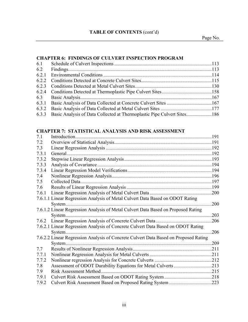
CHAPTER 6: FINDINGS OF CULVERT INSPECTION PROGRAM 6.1 Schedule of Culvert Inspections ................................................................................113 6.2 Findings......................................................................................................................1136.2.1 Environmental Conditions .........................................................................................114 6.2.2 Conditions Detected at Concrete Culvert Sites..........................................................115 6.2.3 Conditions Detected at Metal Culvert Sites...............................................................130 6.2.4 Conditions Detected at Thermoplastic Pipe Culvert Sites.........................................158 6.3 Basic Analysis............................................................................................................167 6.3.1 Basic Analysis of Data Collected at Concrete Culvert Sites .....................................167 6.3.2 Basic Analysis of Data Collected at Metal Culvert Sites ..........................................177 6.3.3 Basic Analysis of Data Collected at Thermoplastic Pipe Culvert Sites.....................186
CHAPTER 7: STATISTICAL ANALYSIS AND RISK ASSESSMENT 7.1 Introduction................................................................................................................1917.2 Overview of Statistical Analysis................................................................................191 7.3 Linear Regression Analysis .......................................................................................192 7.3.1 General.......................................................................................................................1927.3.2 Stepwise Linear Regression Analysis........................................................................193 7.3.3 Analysis of Covariance ..............................................................................................194 7.3.4 Linear Regression Model Verifications .....................................................................194 7.4 Nonlinear Regression Analysis..................................................................................196 7.5 Collected Data............................................................................................................197 7.6 Results of Linear Regression Analysis ......................................................................199 7.6.1 Linear Regression Analysis of Metal Culvert Data ...................................................200 7.6.1.1 Linear Regression Analysis of Metal Culvert Data Based on ODOT Rating
System........................................................................................................................2007.6.1.2 Linear Regression Analysis of Metal Culvert Data Based on Proposed Rating
System........................................................................................................................2037.6.2 Linear Regression Analysis of Concrete Culvert Data ..............................................206 7.6.2.1 Linear Regression Analysis of Concrete Culvert Data Based on ODOT Rating
System........................................................................................................................2067.6.2.2 Linear Regression Analysis of Concrete Culvert Data Based on Proposed Rating
System........................................................................................................................2097.7 Results of Nonlinear Regression Analysis.................................................................211 7.7.1 Nonlinear Regression Analysis for Metal Culverts ...................................................211 7.7.2 Nonlinear regression Analysis for Concrete Culverts ...............................................212 7.8 Assessment of ODOT Durability Equations for Metal Culverts ...............................213 7.9 Risk Assessment Method...........................................................................................215 7.9.1 Culvert Risk Assessment Based on ODOT Rating System.......................................218 7.9.2 Culvert Risk Assessment Based on Proposed Rating System ...................................223
iv
TABLE OF CONTENTS (cont’d) Page No.
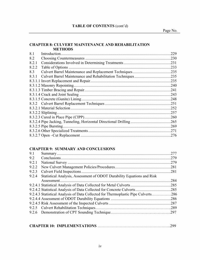
CHAPTER 8: CULVERT MAINTENANCE AND REHABILITATION METHODS
8.1 Introduction................................................................................................................2298.2 Choosing Countermeasures .......................................................................................230 8.2.1 Considerations Involved in Determining Treatments ................................................231 8.2.2 Table of Options ........................................................................................................233 8.3 Culvert Barrel Maintenance and Replacement Techniques.......................................235 8.3.1 Culvert Barrel Maintenance and Rehabilitation Techniques .....................................235 8.3.1.1 Invert Replacement and Repair..................................................................................235 8.3.1.2 Masonry Repointing...................................................................................................240 8.3.1.3 Timber Bracing and Repair........................................................................................241 8.3.1.4 Crack and Joint Sealing .............................................................................................243 8.3.1.5 Concrete (Gunite) Lining...........................................................................................248 8.3.2 Culvert Barrel Replacement Techniques ...................................................................251 8.3.2.1 Material Selection ......................................................................................................252 8.3.2.2 Sliplining....................................................................................................................2578.3.2.3 Cured in Place Pipe (CIPP)........................................................................................260 8.3.2.4 Pipe Jacking, Tunneling, Horizontal Directional Drilling .........................................265 8.3.2.5 Pipe Bursting..............................................................................................................269 8.3.2.6 Other Specialized Treatments ....................................................................................271 8.3.2.7 Open –Cut Replacement ............................................................................................276
CHAPTER 9: SUMMARY AND CONCLUSIONS 9.1 Summary ....................................................................................................................277 9.2 Conclusions................................................................................................................279 9.2.1 National Survey .........................................................................................................279 9.2.2 New Culvert Management Policies/Procedures.........................................................281 9.2.3 Culvert Field Inspections ...........................................................................................281 9.2.4 Statistical Analysis, Assessment of ODOT Durability Equations and Risk
Assessment.................................................................................................................284 9.2.4.1 Statistical Analysis of Data Collected for Metal Culverts .........................................285 9.2.4.2 Statistical Analysis of Data Collected for Concrete Culverts....................................285 9.2.4.3 Statistical Analysis of Data Collected for Thermoplastic Pipe Culverts……………286 9.2.4.4 Assessment of ODOT Durability Equations .............................................................286 9.2.4.5 Risk Assessment of the Inspected Culverts ...............................................................287 9.2.5 Culvert Rehabilitation Techniques………………………………………………….289 9.2.6 Demonstration of CPT Sounding Technique……………………………………….297
CHAPTER 10: IMPLEMENTATIONS ………………………………………………..299
v
TABLE OF CONTENTS (cont’d) Page No.
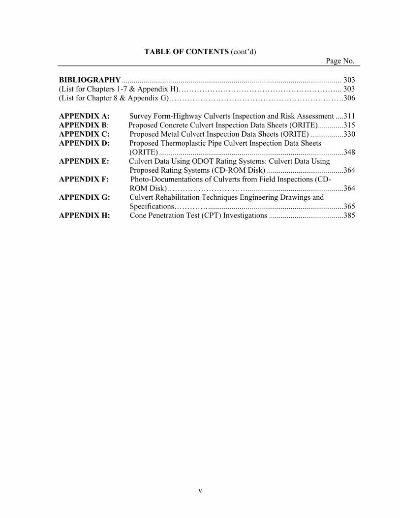
BIBLIOGRAPHY ................................................................................................................ 303(List for Chapters 1-7 & Appendix H)……………………………………………………... 303 (List for Chapter 8 & Appendix G)………………………………………………………….306
APPENDIX A: Survey Form-Highway Culverts Inspection and Risk Assessment ....311 APPENDIX B: Proposed Concrete Culvert Inspection Data Sheets (ORITE).............315 APPENDIX C: Proposed Metal Culvert Inspection Data Sheets (ORITE) .................330 APPENDIX D: Proposed Thermoplastic Pipe Culvert Inspection Data Sheets
(ORITE) ..............................................................................................348 APPENDIX E: Culvert Data Using ODOT Rating Systems: Culvert Data Using
Proposed Rating Systems (CD-ROM Disk) .......................................364 APPENDIX F: Photo-Documentations of Culverts from Field Inspections (CD-
ROM Disk)…………………………..................................................364 APPENDIX G: Culvert Rehabilitation Techniques Engineering Drawings and
Specifications…………......................................................................365 APPENDIX H: Cone Penetration Test (CPT) Investigations ......................................385
vi
LIST OF TABLES Page No.
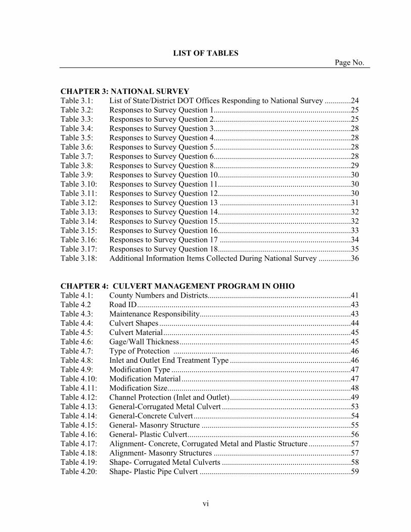
CHAPTER 3: NATIONAL SURVEY Table 3.1: List of State/District DOT Offices Responding to National Survey .............24 Table 3.2: Responses to Survey Question 1....................................................................25 Table 3.3: Responses to Survey Question 2....................................................................25 Table 3.4: Responses to Survey Question 3....................................................................28 Table 3.5: Responses to Survey Question 4....................................................................28 Table 3.6: Responses to Survey Question 5....................................................................28 Table 3.7: Responses to Survey Question 6....................................................................28 Table 3.8: Responses to Survey Question 8....................................................................29 Table 3.9: Responses to Survey Question 10..................................................................30 Table 3.10: Responses to Survey Question 11..................................................................30 Table 3.11: Responses to Survey Question 12..................................................................30 Table 3.12: Responses to Survey Question 13 .................................................................31 Table 3.13: Responses to Survey Question 14..................................................................32 Table 3.14: Responses to Survey Question 15..................................................................32 Table 3.15: Responses to Survey Question 16..................................................................33 Table 3.16: Responses to Survey Question 17 .................................................................34 Table 3.17: Responses to Survey Question 18..................................................................35 Table 3.18: Additional Information Items Collected During National Survey ................36
CHAPTER 4: CULVERT MANAGEMENT PROGRAM IN OHIO Table 4.1: County Numbers and Districts.......................................................................41 Table 4.2 Road ID..........................................................................................................43Table 4.3: Maintenance Responsibility...........................................................................43 Table 4.4: Culvert Shapes ...............................................................................................44Table 4.5: Culvert Material.............................................................................................45Table 4.6: Gage/Wall Thickness.....................................................................................45 Table 4.7: Type of Protection ........................................................................................46Table 4.8: Inlet and Outlet End Treatment Type ............................................................46 Table 4.9: Modification Type .........................................................................................47 Table 4.10: Modification Material....................................................................................47 Table 4.11: Modification Size...........................................................................................48Table 4.12: Channel Protection (Inlet and Outlet)............................................................49 Table 4.13: General-Corrugated Metal Culvert ................................................................53 Table 4.14: General-Concrete Culvert ..............................................................................54 Table 4.15: General- Masonry Structure ..........................................................................55 Table 4.16: General- Plastic Culvert.................................................................................56 Table 4.17: Alignment- Concrete, Corrugated Metal and Plastic Structure .....................57 Table 4.18: Alignment- Masonry Structures ....................................................................57 Table 4.19: Shape- Corrugated Metal Culverts ................................................................58 Table 4.20: Shape- Plastic Pipe Culvert ...........................................................................59
vii
LIST OF TABLES (cont’d) Page No.
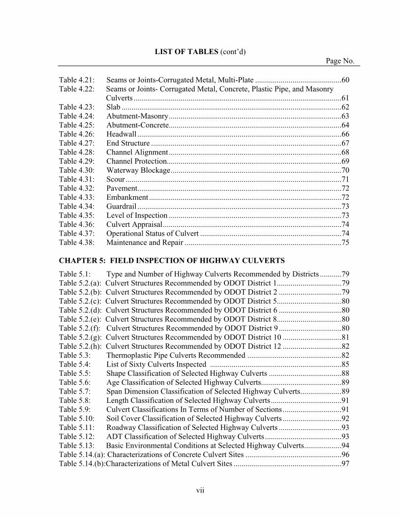
Table 4.21: Seams or Joints-Corrugated Metal, Multi-Plate ............................................60 Table 4.22: Seams or Joints- Corrugated Metal, Concrete, Plastic Pipe, and Masonry
Culverts ..........................................................................................................61 Table 4.23: Slab ................................................................................................................62Table 4.24: Abutment-Masonry........................................................................................63 Table 4.25: Abutment-Concrete........................................................................................64 Table 4.26: Headwall ........................................................................................................66Table 4.27: End Structure .................................................................................................67Table 4.28: Channel Alignment........................................................................................68 Table 4.29: Channel Protection.........................................................................................69 Table 4.30: Waterway Blockage.......................................................................................70 Table 4.31: Scour ..............................................................................................................71Table 4.32: Pavement........................................................................................................72Table 4.33: Embankment ..................................................................................................72Table 4.34: Guardrail ........................................................................................................73Table 4.35: Level of Inspection ........................................................................................73 Table 4.36: Culvert Appraisal...........................................................................................74Table 4.37: Operational Status of Culvert ........................................................................74 Table 4.38: Maintenance and Repair ................................................................................75
CHAPTER 5: FIELD INSPECTION OF HIGHWAY CULVERTS
Table 5.1: Type and Number of Highway Culverts Recommended by Districts ...........79 Table 5.2.(a): Culvert Structures Recommended by ODOT District 1.................................79 Table 5.2.(b): Culvert Structures Recommended by ODOT District 2 ................................79 Table 5.2.(c): Culvert Structures Recommended by ODOT District 5.................................80 Table 5.2.(d): Culvert Structures Recommended by ODOT District 6 ................................80 Table 5.2.(e): Culvert Structures Recommended by ODOT District 8.................................80 Table 5.2.(f): Culvert Structures Recommended by ODOT District 9 ................................80 Table 5.2.(g): Culvert Structures Recommended by ODOT District 10 ..............................81 Table 5.2.(h): Culvert Structures Recommended by ODOT District 12 ..............................82 Table 5.3: Thermoplastic Pipe Culverts Recommended ................................................82 Table 5.4: List of Sixty Culverts Inspected ...................................................................85 Table 5.5: Shape Classification of Selected Highway Culverts .....................................88 Table 5.6: Age Classification of Selected Highway Culverts.........................................89 Table 5.7: Span Dimension Classification of Selected Highway Culverts.....................89 Table 5.8: Length Classification of Selected Highway Culverts....................................91 Table 5.9: Culvert Classifications In Terms of Number of Sections..............................91 Table 5.10: Soil Cover Classification of Selected Highway Culverts ..............................92 Table 5.11: Roadway Classification of Selected Highway Culverts ................................93 Table 5.12: ADT Classification of Selected Highway Culverts .......................................93 Table 5.13: Basic Environmental Conditions at Selected Highway Culverts...................94 Table 5.14.(a): Characterizations of Concrete Culvert Sites .................................................96 Table 5.14.(b):Characterizations of Metal Culvert Sites .......................................................97

viii
LIST OF TABLES (cont’d) Page No.
Table 5.14.(c): Characterization of Thermoplastic Pipe Culvert Sites ..................................98 Table 5.15: ORITE Data Collection for Concrete Culverts..............................................99 Table 5.16: ORITE Data Collection for Metal Culverts ..................................................100 Table 5.17: ORITE Data Collection for Thermoplastic Pipe Culverts.............................100 Table 5.18: Comparisons Between ODOT and Proposed Culvert Rating Systems .........102 Table 5.19: Proposed Rating System for Protective Coating & Invert Paving.................103 Table 5.20: Proposed Rating System for Culvert Inlet & Outlet Sections ......................103 Table 5.21: Proposed Rating System for Footings ..........................................................103 Table 5.22: Proposed Rating System for Headwall/Wingwall ............................................104Table 5.23: Proposed Rating System for Channel (General)............................................105 Table 5.24: List of Field Equipment .................................................................................107 Table 5.25: Cross-Sectional Shape Dimensions Taken Inside Non-Rigid Culverts.........109
CHAPTER 6: FINDINGS OF CULVERT INSPECTION PROGRAM
Table 6.1: Percent Completion Rates of Field Culvert Inspection Work .......................113 Table 6.2: Comparisons of Environmental Conditions ..................................................114 Table 6.3: List of Field Conditions Detected at Concrete Culvert Sites.........................116 Table 6.4: Existence of Characteristic Conditions at Concrete Culvert Sites.................116 Table 6.5: Frequency of Conditions Detected at Concrete Culvert Sites .......................117 Table 6.6: List of Field Conditions Detected at Metal Culvert Sites..............................131 Table 6.7: Existence of Characteristic Conditions at Metal Culvert Sites .....................132 Table 6.8: Frequency of Conditions Detected at Metal Culvert Sites ............................133 Table 6.9: Diameter Measurements Taken Inside HOC-664-22.4 Culvert ...................151 Table 6.10: List of Field Conditions Detected at Thermoplastic Pipe Sites.....................159 Table 6.11: Existence of Characteristic Conditions at Thermoplastic Pipe Sites.............159 Table 6.12: Measured Deflections of Thermoplastic Pipe Culverts .................................160 Table 6.13: Frequency of Conditions at Metal Culvert Sites............................................160 Table 6.14: ODOT Rating Scores for Concrete Culverts .................................................168 Table 6.15: Basic Statistical Summary of Data Presented in Table 6.14 .........................170 Table 6.16: ORITE Rating Scores for Concrete Culverts.................................................172 Table 6.17: Basic Statistical Summary of Data Presented in Table 6.16 .........................176 Table 6.18: ODOT Rating Scores for Metal Culverts ......................................................177 Table 6.19: Basic Statistical Summary of Data Presented in Table 6.18 .........................179 Table 6.20: ORITE Rating Scores for Metal Culverts......................................................181 Table 6.21: Basic Statistical Summary of Data Presented in Table 6.20……………..…185 Table 6.22: ODOT Rating Scores for Thermoplastic Pipe Culverts………………….…186 Table 6.23: Basic Statistical Summary of Data Presented in Table 6.22 .........................187 Table 6.24: ORITE Rating Scores for Thermoplastic Pipe Culverts................................188 Table 6.25: Basic Statistical Summary of Data Presented in Table 6.24 .........................190
ix
LIST OF TABLES (cont’d) Page No.
CHAPTER 7: STATISTICAL ANALYSIS and RISK ASSESSMENT
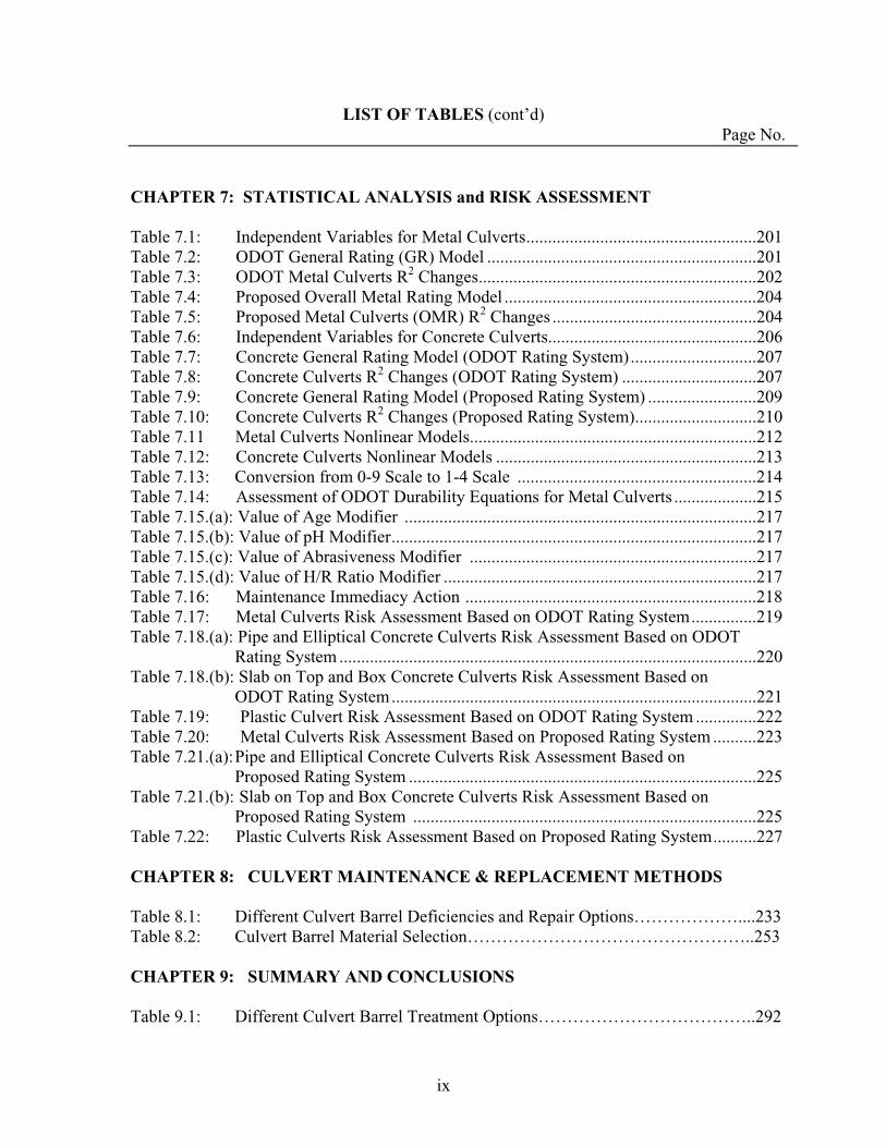
Table 7.1: Independent Variables for Metal Culverts.....................................................201 Table 7.2: ODOT General Rating (GR) Model ..............................................................201 Table 7.3: ODOT Metal Culverts R2 Changes................................................................202 Table 7.4: Proposed Overall Metal Rating Model ..........................................................204 Table 7.5: Proposed Metal Culverts (OMR) R2 Changes ...............................................204 Table 7.6: Independent Variables for Concrete Culverts................................................206 Table 7.7: Concrete General Rating Model (ODOT Rating System).............................207 Table 7.8: Concrete Culverts R2 Changes (ODOT Rating System) ...............................207 Table 7.9: Concrete General Rating Model (Proposed Rating System) .........................209 Table 7.10: Concrete Culverts R2 Changes (Proposed Rating System)............................210 Table 7.11 Metal Culverts Nonlinear Models..................................................................212 Table 7.12: Concrete Culverts Nonlinear Models ............................................................213 Table 7.13: Conversion from 0-9 Scale to 1-4 Scale .......................................................214 Table 7.14: Assessment of ODOT Durability Equations for Metal Culverts ...................215 Table 7.15.(a): Value of Age Modifier .................................................................................217 Table 7.15.(b): Value of pH Modifier....................................................................................217 Table 7.15.(c): Value of Abrasiveness Modifier ..................................................................217 Table 7.15.(d): Value of H/R Ratio Modifier ........................................................................217 Table 7.16: Maintenance Immediacy Action ...................................................................218 Table 7.17: Metal Culverts Risk Assessment Based on ODOT Rating System...............219 Table 7.18.(a): Pipe and Elliptical Concrete Culverts Risk Assessment Based on ODOT
Rating System ................................................................................................220 Table 7.18.(b): Slab on Top and Box Concrete Culverts Risk Assessment Based on
ODOT Rating System....................................................................................221 Table 7.19: Plastic Culvert Risk Assessment Based on ODOT Rating System ..............222 Table 7.20: Metal Culverts Risk Assessment Based on Proposed Rating System ..........223 Table 7.21.(a): Pipe and Elliptical Concrete Culverts Risk Assessment Based on
Proposed Rating System ................................................................................225 Table 7.21.(b): Slab on Top and Box Concrete Culverts Risk Assessment Based on
Proposed Rating System ...............................................................................225 Table 7.22: Plastic Culverts Risk Assessment Based on Proposed Rating System..........227
CHAPTER 8: CULVERT MAINTENANCE & REPLACEMENT METHODS
Table 8.1: Different Culvert Barrel Deficiencies and Repair Options………………....233Table 8.2: Culvert Barrel Material Selection…………………………………………..253
CHAPTER 9: SUMMARY AND CONCLUSIONS
Table 9.1: Different Culvert Barrel Treatment Options………………………………..292
x
LIST OF FIGURES Page No.
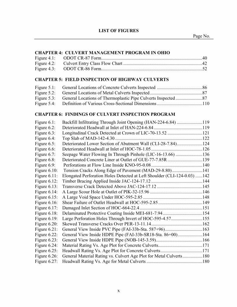
CHAPTER 4: CULVERT MANAGEMENT PROGRAM IN OHIO Figure 4.1: ODOT CR-87 Form.......................................................................................40 Figure 4.2: Culvert Entry Class Flow Chart ....................................................................42 Figure 4.3: ODOT CR-86 Form.......................................................................................52
CHAPTER 5: FIELD INSPECTION OF HIGHWAY CULVERTS
Figure 5.1: General Locations of Concrete Culverts Inspected .......................................86 Figure 5.2: General Locations of Metal Culverts Inspected .............................................87 Figure 5.3: General Locations of Thermoplastic Pipe Culverts Inspected .......................87 Figure 5.4: Definition of Various Cross-Sectional Dimensions .......................................110
CHAPTER 6: FINDINGS OF CULVERT INSPECTION PROGRAM
Figure 6.1: Backfill Infiltrating Through Joint Opening (HAN-224-6.84) ......................119 Figure 6.2: Deteriorated Headwall at Inlet of HAN-224-6.84..........................................119 Figure 6.3: Longitudinal Crack Detected at Crown of LIC-70-13.52 ..............................121 Figure 6.4: Top Slab of MAD-142-4.30 ...........................................................................122 Figure 6.5: Deteriorated Lower Section of Abutment Wall (CLI-28-7.84)......................124 Figure 6.6: Deteriorated Headwall at Inlet of HOC-78-1.05 ............................................126 Figure 6.7: Seepage Water Flowing In Through Pinhole (LIC-16-13.66) .......................136 Figure 6.8: Deteriorated Concrete Liner at Outlet of GUE-77-7.85R ..............................139 Figure 6.9: Perforations at Flow Line Inside KNO-95-0.08............................................140 Figure 6.10: Tension Cracks Along Edge of Pavement (MAD-29-8.80) ..........................141Figure 6.11: Elongated Perforation Holes Detected at Left Shoulder (CLI-124-0.03) ......142 Figure 6.12: Timber Bracing Applied Inside JAC-124-17.12 ............................................144 Figure 6.13: Transverse Crack Detected Above JAC-124-17.12 .......................................145 Figure 6.14: A Large Scour Hole at Outlet of PIK-32-15.96 .............................................146 Figure 6.15: A Large Void Space Under HOC-595-2.85 ...................................................148 Figure 6.16: Shear Failure of Outlet Headwall at HOC-595-2.85......................................149 Figure 6.17: Damaged Inlet Section of HOC-664-22.4......................................................151 Figure 6.18: Delaminated Protective Coating Inside MEI-681-7.94..................................154 Figure 6.19: Large Perforation Holes Through Invert of HOC-595-4.57...........................155 Figure 6.20: Skewed Transverse Cracks Over PER-13-11.14............................................162 Figure 6.21: General View Inside PVC Pipe (FAI-33b-Sta. 587+96)................................163Figure 6.22: General View Inside HDPE Pipe (FAI-33b-SR18-Sta. 86+00) .....................164 Figure 6.23: General View Inside HDPE Pipe (NOB-145-3.59)........................................166 Figure 6.24: Material Rating Vs. Age Plot for Concrete Culverts......................................171 Figure 6.25: Headwall Rating Vs. Age Plot for Concrete Culverts....................................171 Figure 6.26: General Material Rating vs. Culvert Age Plot for Metal Culverts.................180 Figure 6.27: Headwall Rating Vs. Age for Metal Culverts ................................................180

xi
LIST OF FIGURES (cont’d) Page No.
CHAPTER 7: STATISTICAL ANALYSIS and RISK ASSESSMENT
Figure 7.1: Residuals vs. Predicted GR for Metal Culverts (ODOT Rating System) ......202 Figure 7.2: Frequency Bar Chart for Metal Culverts (ODOT Rating System).................203 Figure 7.3 Residuals vs. Predicted OMR for Metal Culverts (Proposed Rating
System) ..........................................................................................................205 Figure 7.4: Frequency Bar Chart for Metal Culverts (Proposed Rating
System) ..........................................................................................................205 Figure 7.5: Residual vs. Predicted GR for Concrete Culverts (ODOT Rating System) ..208 Figure 7.6: Frequency Bar Chart for Concrete Culverts (ODOT Rating System)............208 Figure 7.7: Residual vs. Predicted OCSR for Concrete Culverts (Proposed Rating System)..............................................................................210Figure 7.8: Frequency Bar Chart for Concrete Culverts (Proposed Rating System)...............................................................................................211
CHAPTER 8: CULVERT MAINTENANCE & REPLACEMENT METHODS
Figure 8.1: Average Cost Per Foot for Various Trenchless Technologies…………..….234 Figure 8.2: Typical Ph Values Found in Ohio…………………………………………..236 Figure 8.3: Example of Poor Invert Paving……………………………………………..237Figure 8.4: Example of Good Invert Paving……………………………………………237 Figure 8.5: Timber Bracing that Allowed Debris Collection …………………………..242 Figure 8.6: Poor Joint Sealing that Allowed Infiltration………………………………..245 Figure 8.7: AMEX-10/WEKO-SEAL Installation……………………………………...247 Figure 8.8: PVC LINK-PIPE Installation Process…………………………...…………248 Figure 8.9: Before and After View of Concrete Lined Pipe…………………………….250 Figure 8.10: Views of 15-year-Old Sliplined Pipe (Licking County, Ohio)…..…………260 Figure 8.11: Cured in Place Pipe Installation…………………………………………….264 Figure 8.12: Pipe Jacking Procedure……………………………………………………..267 Figure 8.13: Tunnel Boring Machine Operation…………………………………………268 Figure 8.14: Micro Tunneling Operation………………………………………………...269 Figure 8.15: Pipe Bursting Operation……………………………………………………270 Figure 8.16: Fold and Form Lining Installation………………………………………….272 Figure 8.17: Renewal of 9-foot Sewer with In-situ Form Structural Panels……………..272 Figure 8.18: Machine Wound PVC Installation………………………………………….274 Figure 8.19: Rib Loc RibsteelTM Lining System Installation…………………………….275 Figure 8.20: Full Bore, Traveling Machine System: Rib Loc RotalocTM
Lining System………………………………………………………………276

1
CHAPTER 1: INTRODUCTION
1.1 BACKGROUND
The Ohio Department of Transportation (ODOT) culvert management manual
(2003) defines a culvert as “any structure that conveys water or forms a passageway
through an embankment and is designed to support a super-imposed earth load or other
fill material plus live load with a span, diameter, or multi-cell less than 10 ft (3.1 m)
when measured parallel to the centerline of the roadway.” In the state of Ohio, all bridge
structures with spans 10 ft (3.1 m) or greater (as measured along the centerline of the
road) are required to be inspected annually. In contrast, culverts less than 10 ft (3.1 m) in
span used to be inspected sporadically under varying ODOT district procedures. Periodic
inspection of culverts is an essential element in a culvert management program for
identifying the need for culvert maintenance, repair, or rehabilitation. Field inspection of
a culvert structure can be a major task, since it involves systematic evaluations of the
culvert material conditions, culvert shape and alignments, scouring at culvert ends,
conditions of headwalls/wingwalls, roadway settlement, and embankment slope
conditions.
A comprehensive research project focused on culvert inspection and risk
assessment methods for the Ohio Department of Transportation was greatly needed. The
reasons are as follows:
1. ODOT estimates that there are over 100,000 culvert structures under
Ohio’s priority and general highways. Many of these culverts are
2
inspected only sporadically, although they are either nearing or have
reached their design life. There have been a few cases of culvert failure or
near failure in recent years. Loss of culvert integrity could result in
temporary roadway closure and considerable rehabilitation/replacement
costs. Total collapse of culverts could pose a major safety risk to
motorists.
2. ODOT conducted a comprehensive culvert durability study in 1982. Since
that time, new coatings as well as new culvert materials have been
introduced by the culvert/pipe industry. A wide variety of culvert
materials, treatments, and structural designs prevalent in the short span
culverts today can potentially lead to failure mechanisms that did not exist
20 years ago.
3. A new culvert research project would establish additional case histories
that can be used to further verify the culvert durability methods
established during the ODOT culvert durability study (ODOT, 1982).
4. The Culvert Inspection Manual issued by ODOT in 1990 incorporated the
basic risk assessment method outlined in NCHRP Report No. 251 (1982).
A new culvert research project would produce detailed culvert inspection
data that could be used to propose a more comprehensive culvert risk
assessment method for each major culvert type in Ohio.

3
5. ODOT published the Culvert Management Manual in 2003, which was
aimed at promoting a statewide program for conducting a periodic
inspection of culverts that are less than 10 ft (3.1 m) in span. The manual
presented relatively detailed numerical rating systems for corrugated
metal, concrete (with no protective coating), and thermoplastic pipe
culvert structures. Also, the manual presented detailed numerical rating
systems for the headwalls, channel, embankment slopes, and roadway
surface. Validation of the culvert inspection procedures outlined in the
manual was needed.
6. New sensor technology allows more accurate measurements of aqueous,
soil, and pipe material characteristics in the field and laboratory, providing
comprehensive and quality data collection.
7. Many state DOTs (including ODOT) are facing a large number of aging
infrastructures with limited amounts of available funding. Detailed
information regarding innovative techniques for repairing/replacing aging
culverts would be highly beneficial to DOT personnel. These new
techniques for culvert rehabilitation/placement can be tied into the “better,
smarter, faster bridge” strategic initiative.
4
1.2 OBJECTVES
The primary objective of this project is to reduce the risk of structural failure of
short-span culverts serving major highways in Ohio. This goal will be met by achieving
the following two major components of the project -- 1) detailed field inspection of short-
span culverts that were identified as critical structures in ODOT districts; and 2)
validation of the culvert inspection and rating procedures presented in the ODOT Culvert
Management Manual (ODOT 2003). Tasks of this project are divided into:
Task 1: Obtain from each ODOT district an inventory list of high-priority short-span
culvert structures. Convert the data into a spreadsheet format.
Task 2: Review the FHWA’s and other DOT’s culvert inspection policies and
procedures.
Task 3: Perform field inspections of sixty short-span culverts in Ohio, including those
that are considered as high-priority structures by various ODOT district offices.
Task 4: Verify the overall effectiveness of the inspection and rating procedures
presented in the ODOT Culvert Management Manual (2003).
Task 5: Perform risk assessments of the inspected culverts based on culvert
characteristics and data collected.
5
Task 6: Evaluate and recommend the best maintenance and remedial measures for
highway drainage culverts. Review new innovative techniques for culvert
rehabilitation and replacement.
Task 7: Review ODOT procedures for assessing culvert durability based on field data
and maintenance records.
Task 8: Perform subsurface investigation at selected culvert sites to evaluate the overall
effectiveness of the cone penetration test (CPT) as a new field test method for
culverts.
1.3 OUTLINE OF REPORT
Chapter 2 compiles and summarizes information from an extensive literature
review of culvert inspection and risk assessment issues. Topics addressed in this chapter
include culvert inspection policies and procedures, culvert durability studies, culvert risk
assessment, culvert failure cases, statistical analysis of culvert data, and culvert
rehabilitation/replacement techniques.
Chapter 3 describes the national survey conducted to gain insights into
state/district DOTs’ culvert inspection policies and procedures. The survey consisted of
eighteen questions. Responses to each question are presented and discussed in detail.
Also, additional information supplied by some DOTs is attached to expand the findings
of the survey.

6
Chapter 4 presents the current ODOT culvert inspection policies and rating
systems, as found in the ODOT Culvert Management Manual (2003). First, recent
historical background leading to the issue of this new manual is briefly described. The
new statewide culvert management policies are explained. Then, detailed visual rating
systems presented in the manual are described for concrete, metal, and thermoplastic pipe
culvert structures, as well as for common elements found at many highway culvert sites
(for example, headwalls, channel, embankment slopes, and roadway surface).
Chapters 5 and 6 are devoted to the field inspection phase of the project.
Chapter 5 presents discussions on the inventory data obtained from several ODOT district
offices, the selection process used to identify sixty culvert structures for the field
inspection program, the alternate (higher-resolution) culvert inspection methods proposed
in the current study, the composite characteristics of the selected culverts, and typical
inspection procedures implemented at each culvert site. Chapter 6 provides the
comprehensive findings made during the field inspection program along with some basic
(statistical) data analysis for each major culvert type.
Chapter 7 presents the analytical phase of the research project. In the first
section, statistical analysis is performed using the data collected in the study to identify
key parameters that have a significant influence on the highway culverts in Ohio. The
analysis is repeated using first the data collected by the ODOT rating method and then
the data collected by the proposed rating method to verify the overall effectiveness of the
ODOT culvert rating methods. Statistical tools used in the analysis include linear and
nonlinear multi-variable regression models and tests of significance. In the second
section, the ODOT procedure for estimating the culvert material durability is tested using

7
the data collected in the current study. In the third section, a risk assessment method,
based on the basic method outlined in NCHRP Report 251 (1982) and the results of the
statistical analysis, is proposed for each major culvert type in Ohio.
Chapter 8, prepared by the subcontractor (Jobes Henderson and Associates,
Inc.), describes the current state-of-the-art and state-of-practice for culvert rehabilitation,
upgrade, and replacement. The information gathered from a wide range of sources
(professional journals, conference proceedings, manufacturer handbooks, and reports
issued by FHWA & state DOTs, …) is used to develop this chapter. The topics covered
in the chapter include invert treatment/replacement, masonry repointing, timber bracing,
joint sealing, barrel reshaping, concrete lining, slip-lining, pipe jacking, pipe bursting,
horizontal earth boring, tunneling, and open-cut replacement. A flow chart is included in
the discussions to present guidelines for selecting proper culvert rehabilitation/
replacement methods.
Chapter 9 offers summaries and conclusions for various phases of the current
research project. Chapter 10 concludes the report by offering implementation plans,
which are based on the findings of the research project. Finally, several appendix
sections are attached at the end of the report to provide the national survey form
(Appendix A), ORITE culvert inspection forms (Appendix B, C, D), spread sheets full of
culvert data collected in the study (Appendix E inside CD ROM disk), digital
photographs taken at sixty culvert inspection sites (Appendix F inside CD ROM disk),
engineering specifications and drawings related to various culvert
rehabilitation/replacement techniques (Appendix G; prepared by the sub-contractor), and
results of CPT investigations conducted at selected culvert sites (Appendix H).
8
CHAPTER 2: LITERATURE REVIEW
2.1 INTRODUCTION
Culvert risk assessment, inspection, and durability have been important topics
among transportation engineers and researchers for several decades. There is a large
body of information available on these topics in the literature. The Transportation
Research Board (TRB) has published many technical papers and reports on culvert
related topics. The National Cooperative Highway Research Program (NCHRP) issued
a report on culvert risk assessment (No. 251 in 1982) and two synthesis reports on
culvert durability (No. 50 in 1978; and No. 254 in 1998). The topics of culvert risk
assessment and durability are considered to be closely related.
2.2 CULVERT INSPECTION POLICIES AND PROCEDURES
According to the Culvert Management Manual issued by ODOT (ODOT, 2003),
in the state of Ohio highway culverts having span between 1 and 10 ft (0.3 and 3.1 m)
are recommended to be inspected once every five years. As the span decreases, the
culverts become more difficult to be inspected.
NCHRP Report 303 (2002) presented results from a national survey conducted
on culvert inspection policies and procedures. A total of 155 questionnaires were sent
to various transportation agencies including all state departments of transportation
(DOTs), a number of federal agencies, and a large number of localities, including
county road commissions, county engineering departments, public works departments,
and park and recreation departments. The rate of return from the state DOTs (including
9
Guam and Puerto Rico) was 75% (39 of 52). Localities (including the District of
Columbia) returned 40% (15 of 38) and federal agencies 32% (21 of 65). The return of
all agencies was 48% (75 of 155). The questionnaire requested information about the
agency’s inspection program, maintenance program, record keeping, guidelines for
assessment, repair and rehabilitation, material specifications, service life prediction, and
management system.
Results form the survey indicated that there is no standard state and local
inspection cycle being followed by transportation agencies. There was a higher
percentage of state DOTs with guidelines (37%) than local agencies (33%) and federal
agencies (25%). Most local agencies responding to the survey indicated that they use
the guidelines outlined in FHWA’s Culvert Inspection Manual (1986). From the survey
it appears that most agencies with guidelines try to inspect any culvert from minimum
of 12 in (305 mm) to a maximum of 8 to 10 ft (2.4 to 3.1 m) in diameter. The survey
indicated that most of the transportation agencies (approximately 80%) with guidelines
evaluate the ends of the culvert (inlet end, outlet end, headwalls, and wingwalls) at the
same time the main barrel is inspected. Factors that the respondents considered in their
guidelines are joint failure, deflection, cracking, and corrosion which are considered in
a service life or durability determination. The survey results and the literature review
indicated that most agencies are assessing the debris in the culvert, the scour at the ends
of the culvert, the durability factors, and the physical deficiencies of the culvert. Only
9% of the survey respondents had guidance to select culvert repair methods. Only 7%
of the respondents indicated that they had guidelines to select the culvert rehabilitation
10
method. More respondents (15) indicated that they consider the following factors in
their decision to rehabilitate a culvert: hydraulic capacity, traffic volume, height of fill,
service life, and risk assessment. Service life was factored into the decision process by
13 responding agencies (24%). The survey indicated that 19% of the respondents had a
management system that uses culvert assessment. Little work has been done on
developing a culvert management system. A complete management system would
involve an evaluation of the life-cycle costs, deterioration models for each culvert type
and the effect of each maintenance strategy.
2.3 CULVERT RATING SYSTEM
Kurdziel (1988) reviewed the culvert condition rating systems used in durability
studies conducted by various private, state, and federal agencies. He analyzed and
compared the rating scales used in these studies. He noted that many rating systems
lacked detailed descriptions of the levels of material distress. In order to meet his
objective, he modified the FHWA’s culvert rating systems (FHWA, 1985) with the
information obtained from reviewing various state DOTs’ data. A new material
durability rating system for both metal and concrete culvert was proposed based on
these comparisons.
2.4 CULVERT DURABILITY STUDIES
NCHRP Report 50 (1978) defined durability as the material’s ability to resist
degradation as a result of forces of chemical or electrochemical corrosion and
mechanical abrasion. In culvert and storms drains, durability is a means of stating and

11
comparing useful service lives when limited by the culvert material performance.
Culvert durability is usually affected by two mechanisms – corrosion and abrasion.
NCHRP Report 254 (1998) stated that parameters most frequently related to
chemical and electrochemical corrosion are soil-side and water-side pH, soil-side and
water-side electrical resistivity, chemical composition (including the concentration and
distribution of oxygen) of soil surrounding the culvert, and chemical and mineral
composition of soil in the drainage area feeding the culvert. The report cited the usage
of thermoplastic materials as a significant change, and noted that linings for metal
culverts continued to encounter durability problems.
The ODOT Culvert Durability Study (ODOT, 1982) documented approximately
eight thousand culverts with service life ranging from recently installed to over forty
years. The majority of the culverts in the 1982 inventory were constructed of steel and
concrete. The inventory provided information about the corrosion and abrasion
resistance of various types of culvert and protection materials used for culverts in the
state of Ohio. A total of 531 concrete pipe culverts, 386 structural steel plate pipe
(SSP) culverts, and 624 corrugated steel pipe (CSP) culverts were inspected between
1972 and 1975. Of the 624 CSPs, 127 were bituminous coated (AASHTO M 190 Type
A) and 302 were bituminous coated with paved inverts (AASHTO M 190 Type B and
C). These culverts were nearly all 42 in (1.07 m) or larger in size. The collected data at
each site included pipe size, material type, and wall thickness; type of pipe protection;
depth and velocity of dry weather flow; presence of abrasive material and apparent
12
effect; amount and type of sediment or debris or both; pH of water, streambed, and
embankment; electric resistivity of water, streambed, and embankment; description of
protection and protection rating; description of base pipe and base pipe rating;
qualitative chemical tests; and metal cores. Detailed analyses were performed to
evaluate the effects of various environmental factors on the durability of concrete pipe,
galvanized corrugated steel pipe, and bituminous protection of corrugated steel pipe.
Equations and graphs were presented to predict the service lives of these culvert
materials. This phase of the study was in general limited to culverts with diameter or
rise greater than 42 in (1.07 m). The ODOT study pointed out that the environmental
conditions in Ohio were somewhat unique (or aggressive) compared to those in most
other states. This is because a large area in Ohio is characterized by non-neutral pH
flow and abrasive geological materials. Different factors impact service life of each
culvert type. Both reinforced concrete and corrugated metal culverts are susceptible to
corrosion and abrasion, depending on the type of coating and service conditions.
Corrosive actions intensify under soil conditions with low pH, low resistivity, and
increased moisture and temperature. Abrasive actions amplify with increased drainage
flow velocities and coarser, heavier bed loads. Thermoplastic culverts are more
corrosion and abrasion resistant.
Hurd (1986) evaluated the durability of concrete pipe, galvanized corrugated
steel pipe, and bituminous protection corrugated steel pipe in Ohio. The data in this
paper were taken from the ODOT Culvert Durability Study (ODOT, 1982). Detailed
analyses were performed to evaluate the effects of various environmental factors on the

13
durability of these materials. Water pH and abrasiveness of flow were the only
environmental parameters to have a significant effect on the deterioration rate of
corrugated steel pipe. Below a value of 7.0, water pH had a significant effect on
concrete pipe performance. Predictive equations and graphs were presented, that can be
used to estimate the service lives of concrete and corrugated steel pipe culverts. None
of the environmental parameters studied had a significant effect on the performance of
the bituminous protection. He concluded that the average lives of bituminous coating
and coating with invert paving were 3.2 and 18.7 years, respectively, due to debonding
problem they develop.
Temple and Cumbaa (1986) investigated the performance of coated and
uncoated, corrugated, galvanized steel and aluminum drainage pipes in Louisiana. Ten
types of metal drainage pipes were installed at each of ten locations in 1973. Test sites
were selected on the basis of the pH and the electrical resistivity of the soil. One pair of
each type of culvert was installed at each site. Every two years, one designated culvert
of each of the pairs was removed and subjectively rated by a panel. They concluded
that the 16-gauge asphalt-coated aluminum; the 14-gauge asbestos-bonded, asphalt
coated galvanized steel; and the 16-gauge galvanized steel with a 12-mil (0.30-mm)
interior and 5-mil (0.13-mm) exterior polyethylene coating were the test pipes with the
most resistance to corrosion at the majority of the test sites. They also concluded that
coatings provided more resistance to corrosion. The thicker polymeric coatings
provided more protection against corrosion than the thinner polymeric coatings.

14
2.5 CULVERT FIELD PERFORMANCE
Hurd (1986) evaluated the 10-year performance of protective linings for
concrete and galvanized steel culverts at corrosive and abrasive sites in Ohio. A total of
26 epoxy-coated concrete pipe culverts in Ohio, 57 polymeric-coated corrugated steel
pipe culverts in Ohio, and 38 asbestos-bonded bituminous-coated-and-paved corrugated
steel pipe culverts in Indiana, Kentucky, and Ohio were inspected one or more times
between 1972 and 1986. The culvert sites were primarily located in those areas of the
state that had more aggressive environmental conditions. The collected data at each
site included pipe size, material type, and wall thickness; type of pipe protection; depth
and velocity of dry weather flow; presence of abrasive material and apparent effect;
amount and type of sediment or debris or both; pH of water; and description of
protection and protection rating. Based on the field observations, the following
conclusions were made regarding the performance of the protective linings. Properly
applied epoxy coating provided satisfactory protection for concrete pipe at low pH sites
with nonabrasive to moderately abrasive flow. Direct sunlight caused debonding of the
epoxy coating. Sunlight, abrasive flow, and low pH flow all caused delamination of the
polymeric coating. Asbestos-bonded bituminous coating with invert paving provided
satisfactory protection of corrugated steel pipe at nonabrasive to moderately abrasive
low pH sites. Abrasive flow was mainly responsible for deterioration of the asbestos-
bonded bituminous coating.
Hurd (1986) collected and analyzed data concerning structural performance and
durability of corrugated HDPE pipes in Ohio. A total of 172 corrugated polyethylene
15
pipe culverts 12 through 24 in (0.30 through 0.61 m) in diameter and ranging in age
from 0 to 4 years were inspected in the summer of 1985. The data collected for these
pipes included, pipe diameter, cover of the pipe, type of backfill, culvert age, average
daily traffic, pipe deflection, flow depth and velocity, bed load depth and particle size,
water pH, and pipe slope. The data indicated that the corrugated HDPE pipes were
resistant to abrasive flow. Culvert deflections stabilized within 2 to 4 years. Shallow
cover and heavy truck traffic did not appear to be detrimental to the structural
performance of corrugated HDPE pipe culverts. Deflection appeared to be built into the
culverts instead of caused by highway loadings. Exposed culvert ends were vulnerable
to damage by mowing machines and other maintenance equipment. Exposure to
sunlight did not appear to affect the condition of the exposed ends. He recommended
that the wall thickness of some HDPE pipe products be increased to provide greater
ring stiffness.
Degler et al. (1988) analyzed field inspection data of 890 corrugated metal pipe-
arch culverts in Ohio. The inspection was conducted by each of the twelve ODOT
district offices. The inspection consisted of a visual examination and limited
dimensional measurements. The pipe-arch was selected because this type of structure
tends to have structural problems more than any other corrugated metal plate (CMP). It
also represents approximately 50 percent of Ohio’s CMP population. The data showed
that the dominant failure/deterioration modes were heavy corrosion of plates and
fasteners (27%), significant flattening of the crown (12%), and cracking of plates at
corner radius bolt-line (3%). Statistical analysis was conducted to find correlation
16
between the inspection items. The results indicated strong correlations between age and
durability, between geographical location and durability, and between shape problems
and crack problem. An approximately linear relationship was observed between the
durability rating and age, until the age reached 35 years old, at which the durability
rating worsened at more rapid rates. Culverts in southeastern Ohio had the lowest
durability scores due to low pH and higher abrasion bed loads. An approximately linear
relationship was observed between shape and cracking and seam cracking problem. No
correlation was indicated between the depth of cover and the shape distortion,
durability, or cracking problems.
Between 1994 and 1998, the Missouri Department of Transportation (MDOT,
2001) inspected 230 culverts in seventy-one counties throughout ten districts. The types
of the culvert inspected included double-wall polyethylene (DWP), single-wall
polyethylene (CPE), poly-liner, aluminized, aluminum, polymer coated, concrete box,
poly-vinyl chloride (PVC), PVC liner, in-situ form, fiberglass, slotted drain, galvanized
and reinforced concrete. All culverts were visually inspected to determine if any
damage, erosion, or abrasion has occurred since they were last inspected. A picture was
taken of the inlet and outlet of each pipe. Beginning in 1995, a video was taken inside
the culvert to determine the condition of the joints, view any possible deflections along
the length of the pipe, and discover any deterioration of the culvert itself. All videos
and pictures were kept on file. Seven tests were conducted by the culvert inspection
crew. These tests included soil pH, water pH, 4-pin resistance, soil box resistance, soil
to pipe resistance, water hardness and pipe thickness. All these tests were conducted at

17
the inlet end of the pipe, unless the inlet was not accessible, then the outlet end was
tested. Some of these tests provided significant data; others did not. The soil to pipe
resistance and water hardness did not show any consistency or trends. The hardness of
the water did not affect the culvert unless it stayed for an extremely long time. Mower
damage was one of the most common problems detected by the inspection crew.
Another problem was deformation or indentation of the pipe. Other problems existed
but they were minimal. Overall, the condition of the culverts was favorable. This study
has shown correlation of field performance and service life of pipes to field testing,
such as pH and soil resistivity. Other testing conducted in this study, identified neither
notable trends or provided little correlation to the performance. Data collected over the
years of the study has determined that, on average, steel pipe will last 40 years. Many
factors affect corrosion of meal pipe, such as soil pH, water pH, soil resistivity,
fertilizers, herbicides, coal cinders, and deicing salts. Seventy-six percent (76%) of the
galvanized steel pipes in this study were replaced because the invert was rusted out.
There was not enough information to form any statistical conclusions about the life
span of plastic pipe, which is expected to last 75 years, according to its manufacturers.
Like steel, concrete culverts are susceptible to corrosion and abrasion. Low pH, high
level of sulfates in the soil or water, and acid run-off from mining areas can be of
concern with concrete. The majority of concrete culverts had a high structural and
material durability rating. It was noted that concrete culverts have demonstrated a
service life of at least 75 years and very well may last 100 years, as originally
predicted.

18
2.6 STATISTICAL ANALYSIS AND RISK ASSESSMENT
Hadipriono et al. (1988) used regression analysis to predict service life of
concrete pipe culverts. Five hundred twenty-one sections of concrete culverts inspected
by ODOT were used in the analyses (ODOT Culvert Durability Study, 1982). Variables
considered in this study included: pipe age, pipe size, depth of flow, flow velocity,
presence of abrasive materials, presence of sediment or debris, protection rating, slope
of pipe, and pH level of water. The independent variables used in the analysis included:
age of the pipe, rise or diameter of the pipe, flow depth, flow velocity rating, sediment
depth, pipe slope, and pH of water. The dependant variable is concrete pipe rating. Two
types of regression models were used. One was additive (which had a standard linear
form), and the other was multiplicative. The multiplicative model used log transforms.
The fact that concrete culvert rating (instead of age) was used as the dependant variable
restricted the use of this model to the prediction of service lives of culvert given the
knowledge of the independent variables. The results indicated an estimated expected
life of 86 years for concrete culverts. Such service life estimates may be of value to
engineers performing life-cycle cost studies of these types of culverts.
NCHRP 251 (1982) presented a risk assessment model for bridge substructures
below the waterline. Risk assessment categories included scour, undermining, section
loss, general deterioration of material, and settlement. Equation 2.1 shows the model
UI = IA + M .................................................................................................. Eq. 2.1
where UI = Urgency Index; IA = Initial Assessment; and M = Modification.

19
Appendix G of the report presented the substructures’ condition below the waterline for
urgency index, initial assessment and modification assessment and gave a number for
each condition. The assessment modification should be algebraically added to the initial
assessment to produce the maintenance urgency index. Once an urgency index is
selected, the type of action to be taken in the inspection process and by maintenance
forces can then be selected as shown below:
UI = 9 --- No repairs & actions needed.
UI = 8 --- No repairs needed. List special items for next regular inspection.
UI = 7 --- No immediate plans for repair. Possibly increase the level of inspection.
UI = 6 --- Add to the scheduled maintenance work by the end of the next season.
UI = 5 --- Place in the current maintenance schedule.
UI = 4 --- [Priority] Review the maintenance work schedule for the current season.
Adjust it if possible.
UI = 3 --- [High Priority] Perform maintenance work as soon as possible in the
current season.
UI = 2 --- [Highest Priority] Discontinue other maintenance work if required. Take
emergency subsidiary actions if needed (ex. reduced load posting, one-
lane traffic, no trucks)
UI = 1 --- [Emergency] Emergency actions required. Reroute traffic and close.
UI = 0 --- Close for repairs.

20
2.7 CULVERT FAILURES
Cowherd and Corda (1994) examined flexible metal culvert case history,
including two failed cases and several non-failure cases, to evaluate the degree of
deformation (flattening) that can be tolerated by these structures without failure. The
data from the two failed cases indicated that the collapse had occurred at top mid-
ordinate flattening of 45 to 55%. For many culverts that did not fail, the top mid-
ordinate flattening varied from 22 to 34%. A correlation was established between the
type of soil backfill and potential structural flattening. Based on the findings, they
recommended the following action to be taken if the reduction in the top mid-ordinate
is as follows:
< 20% ........... No action required
20 to 25% ..... Reduced legal load to 90% of H-20. Inspect at 6 month interval
25 to 30%. ..... Reduced legal load to 75% of H-20. Inspect at 6 month interval
> 30% ........... Close the road. Conduct a detailed analysis to decide the course
of action.
2.8 CULVERT REHABILITATION AND REPLACEMENT TECHNIQUES
NCHRP Synthesis Report No. 303 (2002) presented comprehensive summary
information on the best available technologies for culvert repair and rehabilitation.
There are five levels of actions in any culvert management program:

21
Level 1: Routine Maintenance
Level 2: Preventive Maintenance
Level 3: Rehabilitation
Level 4: Upgrade
Level 5: Replacement
Level 1 (routine maintenance) is any basic work needed to keep the culvert in
safe, functioning condition by repairing specific defects as they occur. Examples of the
Level 1 actions include ditch cleaning and debris and sediment removal.
Level 2 (preventive maintenance) is any more extensive work to stop light
deterioration and prevent progressive deterioration. Examples of the Level 2 actions
include ditch repair, joint sealing, concrete patching and mortar repair, and scour
prevention.
Level 3 (rehabilitation) consists of any extensive work performed to
repair/recondition portion(s) of the culvert and extend remaining service life. Examples
of the Level 3 actions include repair of headwalls and wingwalls, invert paving, repair
of scour, embankment slope stabilization, streambed paving, improvement of inlet
configuration, and installation of debris collectors.
Level 4 (upgrade) is any work to upgrade the condition of the culvert to a new
status. Examples of the Level 4 actions include lining of the barrel, and culvert
extension. There are some innovative lining techniques currently being marketed by
the industry. For example, a seamless textile/thermoplastic-based liner can be inserted
into the aged pipe structure, heated, and pressurized inside the pipe to expand and fit

22
tightly to the shape of the host pipe. This technique provides a “cured-in-place” liner.
A study by Johnson and Zollars (1992) at Minnesota DOT showed that culvert relining
could be inexpensive and minimally disruptive.
Level 5 (replacement) consists of any major work to replace the existing culvert
with a completely new culvert having a new service life. Examples of the Level 5
actions include conventional open-cut technique and new innovative trenchless
techniques. The conventional open excavation method is still the primary option for
replacing the underground structure. However, this method is disruptive to motorists,
poses safety-hazards to the workers in the trench, may be costly (depending on the
trench size), and may also create conflicts with other utility lines. The relatively new
trenchless technology includes the pipe bursting (PB) method and the pipe jacking (PJ)
method. In the PB method, a bursting body is pulled through the host pipe (to be
replaced). The pipe wall is destroyed by static or dynamic forces applied by the
bursting body. Fragments of the host pipe wall are pushed into the surrounding soil.
The new pipe is then installed immediately behind the bursting body before the hole
has a chance to collapse. The PB method is suitable for pipes that are made of brittle
materials. In the PJ method, the pipe to be replaced is re-bored, destroyed, and
conveyed by a remote control tunneling machine. The new pipe is jacked hydraulically
directly behind the tunneling machine. This method is more suitable for flexible pipes
that cannot be easily burst by the PB method. In both of these methods, the diameter of
the new pipe can be greater than the diameter of the old pipe. Additional information
on the two innovative methods can be found in a paper by Stein (1990).

23
CHAPTER 3: NATIONAL SURVEY
3.1 INTRODUCTION
As stated in Chapter 1, one of the tasks in the research project was to conduct a
national survey on highway culvert management policies and inspection/rating
procedures. Findings from this task could have implications for the other tasks and
implementation plans. Since ODOT is in the initial stage of implementing new
comprehensive statewide management policies and risk assessment procedures for
highway culverts, the data collected from the survey could be beneficial to highlight
national trends, as well as innovative and effective policies/programs practiced by some
highway agencies. Literature review had indicated that some state departments of
transportation (for example New York) had developed comprehensive approaches for
culvert management. This chapter presents the survey methodology, descriptions of the
survey questions, survey results, and additional information collected during the survey.
3.2 SURVEY METHODOLOGY
The questions on the survey were initially conceived by the ORITE researchers
based on their past experience with highway culvert structures and additional insights
gained through the literature review. The initial set of questions was then reviewed by
the ODOT personnel, and comments were incorporated into the survey form. Once the
survey form was finalized, it was sent electronically to hydraulic engineers or equivalents
in DOT agencies, via the ODOT mailing list.
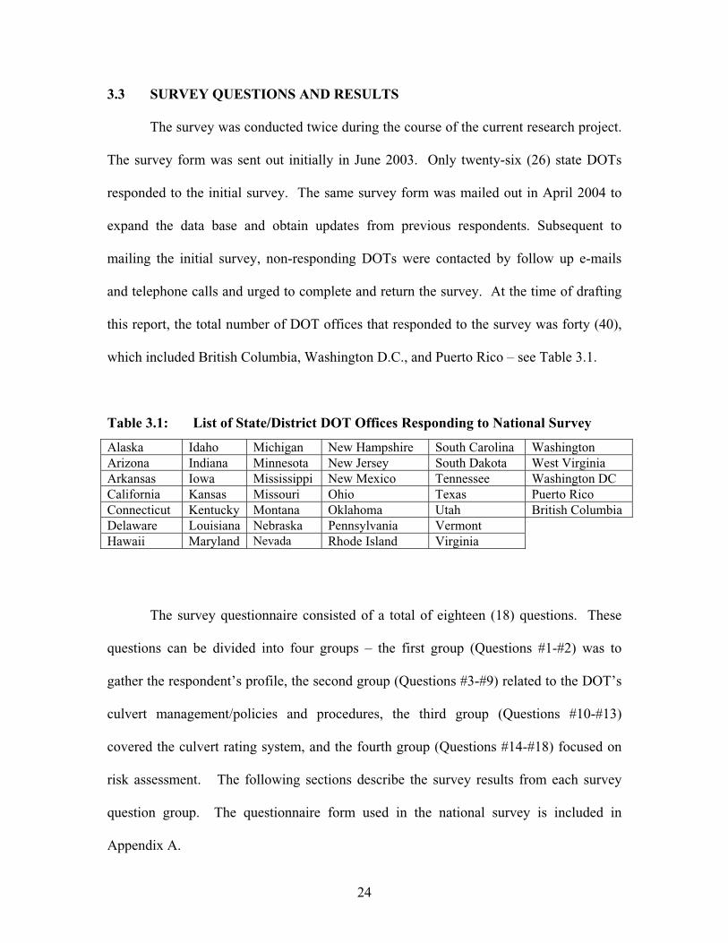
24
3.3 SURVEY QUESTIONS AND RESULTS
The survey was conducted twice during the course of the current research project.
The survey form was sent out initially in June 2003. Only twenty-six (26) state DOTs
responded to the initial survey. The same survey form was mailed out in April 2004 to
expand the data base and obtain updates from previous respondents. Subsequent to
mailing the initial survey, non-responding DOTs were contacted by follow up e-mails
and telephone calls and urged to complete and return the survey. At the time of drafting
this report, the total number of DOT offices that responded to the survey was forty (40),
which included British Columbia, Washington D.C., and Puerto Rico – see Table 3.1.
Table 3.1: List of State/District DOT Offices Responding to National Survey
Alaska Idaho Michigan New Hampshire South Carolina Washington Arizona Indiana Minnesota New Jersey South Dakota West Virginia Arkansas Iowa Mississippi New Mexico Tennessee Washington DC California Kansas Missouri Ohio Texas Puerto Rico Connecticut Kentucky Montana Oklahoma Utah British Columbia Delaware Louisiana Nebraska Pennsylvania Vermont Hawaii Maryland Nevada Rhode Island Virginia
The survey questionnaire consisted of a total of eighteen (18) questions. These
questions can be divided into four groups – the first group (Questions #1-#2) was to
gather the respondent’s profile, the second group (Questions #3-#9) related to the DOT’s
culvert management/policies and procedures, the third group (Questions #10-#13)
covered the culvert rating system, and the fourth group (Questions #14-#18) focused on
risk assessment. The following sections describe the survey results from each survey
question group. The questionnaire form used in the national survey is included in
Appendix A.
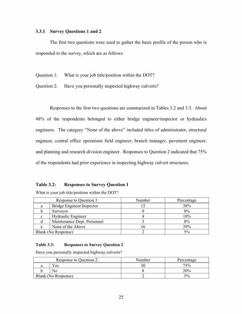
25
3.3.1 Survey Questions 1 and 2
The first two questions were used to gather the basic profile of the person who is
responded to the survey, which are as follows:
Question 1: What is your job title/position within the DOT?
Question 2: Have you personally inspected highway culverts?
Responses to the first two questions are summarized in Tables 3.2 and 3.3. About
48% of the respondents belonged to either bridge engineer/inspector or hydraulics
engineers. The category “None of the above” included titles of administrator, structural
engineer, central office operations field engineer, branch manager, pavement engineer,
and planning and research division engineer. Responses to Question 2 indicated that 75%
of the respondents had prior experience in inspecting highway culvert structures.
Table 3.2: Responses to Survey Question 1
What is your job title/position within the DOT?
Response to Question 1: Number Percentage a Bridge Engineer/Inspector 15 38% b Surveyor 0 0% c Hydraulic Engineer 4 10% d Maintenance Dept. Personnel 3 8% e None of the Above 16 39%
Blank (No Response) 2 5%
Table 3.3: Responses to Survey Question 2
Have you personally inspected highway culverts?
Response to Question 2: Number Percentage a Yes 30 75% b No 8 20%
Blank (No Response) 2 5%
26
3.3.2 Survey Questions 3 Through 9
The next several questions were designed to learn the current culvert management
policies/practices of the agencies:
Question 3: Who performs the bulk of culvert inspections in your DOT?
Question 4: Does your DOT address Confined Space issues with regard to culverts?
Question 5: In your state, how is highway culvert defined?
Question 6: Does your DOT have any inspection policies for highway culverts?
Question 7: If the answer to Question 6 is “Yes,” provide a brief explanation of the
inspection guidelines/policy.
Question 8: Does your DOT’s culvert inspection policy specify the frequency of
culvert inspection?
Question 9: If the answer to Question 8 is “Yes,” specify the frequency.
Responses to these questions are summarized in Tables 3.4 through 3.8.
According to Table 3.4, a variety of personnel are performing field culvert inspections.
There appears to be no one specific type of personnel who engage in the culvert
inspection work in many states. The category lumped as “Others” included consultants
(contractors) and maintenance personnel. According to Table 3.5, nearly half of the
state/district DOTs are addressing the confined space issues. For state DOT respondents,
37 respondents (= 46%) are addressing confined space issues.

27
In Table 3.6, the “None of the above” category constituted the majority of the
responses (85%). The responses indicated that about 60 to 70% of the state DOTs
borrowed the AASHTO definition (span < 20 ft or 6.1 m), as applied to culverts. Other
responses included currently under development, no definitions, some type of conduit for
draining water, drainage pipes, and drainage opening below a roadway embankment
having no distinction between superstructure and substructure and a minimum opening
size of 36 ft2 (3.3 m2).
According to Table 3.7, about 60% of the agencies have developed culvert
inspection policies that specify the culvert inspection frequency. For just state DOTs,
54% responded affirmatively. Table 3.8 indicates that about 55% of the DOTs that
responded “yes” to Question 8 specified a 1-2 year cycle for inspecting culverts. Some
state DOTs reported having dual frequency requirements. For example, Minnesota DOT
inspects culverts larger than 10 ft (3.1 m) in span at 1-2 year intervals and smaller
culverts in a 5-year cycle. Virginia DOT stated that they inspect large culverts (span 10-
20 ft or 3.1-6.1 m) every 2 years and smaller culverts at 4-year intervals. The response
“Other” included 3 to 60 months, 1 to 4 years, and every 5 years. These responses to
Question 8 confirm the previous finding reported in NCHRP Report No. 303 (2002) that
there is no standard culvert inspection cycle being followed by all highway agencies.

28
Table 3.4: Responses to Survey Question 3
Who performs the bulk of culvert inspections in your DOT?
Response to Question 3: Number Percentage a Highway Workers 12 30% b Engineers 6 15% c Bridge Inspectors/Crews 3 7.5% d All of the Above 4 10% e Others 14 35%
Blank (No Response) 1 25%
Table 3.5: Responses to Survey Question 4
Does your DOT address Confined Space issues with regard to culverts?
Response to Question 4: Number Percentage a Yes 18 44% b No 17 43% c Don’t Know 0 0%
Blank (No Response) 5 13%
Table 3.6: Responses to Survey Question 5
In your state, how is highway culvert defined?
Response to Question 5: Number Percentage a Span 6 ft (1.83 m) or less 2 5% b Span 8 ft (2.44 m) or less 0 0% c Span 10 ft (3.05 m) or less 1 2.5% d Span 15 ft (4.57 m) or less 1 2.5% E None of the above 34 85%
Blank (No Response) 2 5%
Table 3.7: Responses to Survey Question 6
Does your DOT have any inspection policies for highway culverts?
Response to Question 6: Number Percentage a Yes 24 60% b No 13 32.5% c Don’t Know 1 2.5%
Blank (No Response) 2 5%

29
Table 3.8: Responses to Survey Question 8
Does your DOT’s culvert inspection policy specify the frequency of culvert inspection?
Response to Question 8: Number Percentage a Yes 22 55% b No 6 15% c Don’t know 1 2.5% d Not applicable 2 27.5%
If the answer to Question 8 is “Yes,” specify the frequency.
Response to Question 8: Number Percentage a Less than 1 year 0 0% b 1-2 years 12 48% c 3-5 years 4 16% d More than 5 years 0 10% e Other 9 36%
3.3.3 Survey Questions 10 Through 13
The third group of questions was developed to ascertain information regarding the
culvert rating systems used by the other DOTs:
Question 10: Has your DOT developed a culvert inspection manual?
Question 11: Does your DOT apply any numerical rating systems to highway culverts?
Question 12: Who developed your DOT’s culvert numerical rating system?
Question 13: Does your DOT have any numerical rating systems for thermoplastic pipe
inspection?
Responses to the above questions are summarized in Tables 3.9 through 3.12.
From Table 3.9, only five state DOTs (Arizona, California, Connecticut, Indiana, Kansas),
other than Ohio, have developed their own culvert inspection manual. Results in Table
3.10 show that 55% of respondents for 54% of the state DOTs are applying numerical
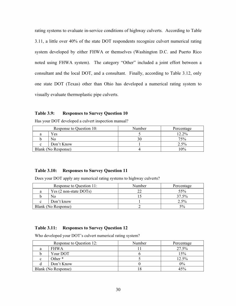
30
rating systems to evaluate in-service conditions of highway culverts. According to Table
3.11, a little over 40% of the state DOT respondents recognize culvert numerical rating
system developed by either FHWA or themselves (Washington D.C. and Puerto Rico
noted using FHWA system). The category “Other” included a joint effort between a
consultant and the local DOT, and a consultant. Finally, according to Table 3.12, only
one state DOT (Texas) other than Ohio has developed a numerical rating system to
visually evaluate thermoplastic pipe culverts.
Table 3.9: Responses to Survey Question 10
Has your DOT developed a culvert inspection manual?
Response to Question 10: Number Percentage a Yes 5 12.2% b No 30 75% c Don’t Know 1 2.5%
Blank (No Response) 4 10%
Table 3.10: Responses to Survey Question 11
Does your DOT apply any numerical rating systems to highway culverts?
Response to Question 11: Number Percentage a Yes (2 non-state DOTs) 22 55% b No 15 37.5% c Don’t know 1 2.5%
Blank (No Response) 2 5%
Table 3.11: Responses to Survey Question 12
Who developed your DOT’s culvert numerical rating system?
Response to Question 12: Number Percentage a FHWA 11 27.5% b Your DOT 6 15% c Other * 5 12.5% d Don’t Know 0 0%
Blank (No Response) 18 45%

31
Table 3.12: Responses to Survey Question 13
Does your DOT have any numerical rating systems for thermoplastic pipe inspection?
Response to Question 13: Number Percentage a Yes 1 (Texas) 2.5% b No 19 47.5% c Don’t know 3 7.5%
Blank (No Response) 17 42.5%
3.3.4 Survey Questions 14 and 15
The next group of questions focused on risk assessment methods utilized by each
local agency:
Question 14: Does your DOT utilize the culvert risk assessment method proposed by
the NCHRP Report 251?
Question 15: Who developed your DOT’s culvert risk assessment system?
Responses to these two questions are summarized in Tables 3.13 and 3.14. The
results in Table 3.13 show that most state DOT personnel do not use or are not familiar
with the NCHRP Report 251. Only five state DOTs have developed their own culvert
risk assessment procedure (see Table 3.14). These include California, Michigan,
Minnesota, Pennsylvania, and Tennessee. The response “Other” included having no risk
assessment system in place, risk assessment method currently under development, and
utilization of the regular NBIS criteria.

32
Table 3.13: Responses to Survey Question 14
Does your DOT utilize the culvert risk assessment method proposed by the NCHRP Report 251?
Response to Question 14: Number Percentage a Yes 0 0% b No 30 75% c Don’t know 8 20%
Blank (No Response) 2 5%
Table 3.14: Responses to Survey Question 15
Who developed your DOT’s culvert risk assessment system?
Response to Question 15: Number Percentage a Your DOT 5 12.5% b Other * 8 20% c Don’t know 4 10%
Blank (No Response) 23 57.5%
3.3.5 Survey Questions 16 through 18
The remaining three questions dealt with a few remaining topics of interest, such
as the development of a computer database, the decision process for culvert replacement,
and the use of special inspection tools:
Question 16: Do you have a computer database for the highway culverts in your state?
Question 17: How does your DOT decide when to replace each highway culvert?
Question 18: Does your DOT or the subcontractor that you retain, utilize any special
equipment to conduct visual inspection of small culverts?
Responses to the first two questions are summarized in Tables 3.15 through 3.17.
According to Table 3.15, about 57% (21 out of 37) of the responding state DOTs have a
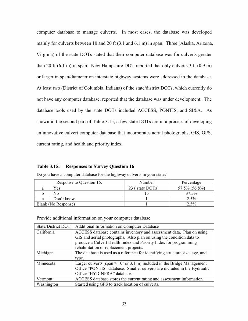
33
computer database to manage culverts. In most cases, the database was developed
mainly for culverts between 10 and 20 ft (3.1 and 6.1 m) in span. Three (Alaska, Arizona,
Virginia) of the state DOTs stated that their computer database was for culverts greater
than 20 ft (6.1 m) in span. New Hampshire DOT reported that only culverts 3 ft (0.9 m)
or larger in span/diameter on interstate highway systems were addressed in the database.
At least two (District of Columbia, Indiana) of the state/district DOTs, which currently do
not have any computer database, reported that the database was under development. The
database tools used by the state DOTs included ACCESS, PONTIS, and SI&A. As
shown in the second part of Table 3.15, a few state DOTs are in a process of developing
an innovative culvert computer database that incorporates aerial photographs, GIS, GPS,
current rating, and health and priority index.
Table 3.15: Responses to Survey Question 16
Do you have a computer database for the highway culverts in your state?
Response to Question 16: Number Percentage a Yes 23 ( state DOTs) 57.5% (56.8%) b No 15 37.5% c Don’t know 1 2.5%
Blank (No Response) 1 2.5%
Provide additional information on your computer database.
State/District DOT Additional Information on Computer Database California ACCESS database contains inventory and assessment data. Plan on using
GIS and aerial photographs. Also plan on using the condition data to produce a Culvert Health Index and Priority Index for programming rehabilitation or replacement projects.
Michigan The database is used as a reference for identifying structure size, age, and type.
Minnesota Larger culverts (span > 10’ or 3.1 m) included in the Bridge Management Office “PONTIS” database. Smaller culverts are included in the Hydraulic Office “HYDINFRA” database.
Vermont ACCESS database stores the current rating and assessment information. Washington Started using GPS to track location of culverts.

34
Table 3.16 indicates that most state DOTs base their decision to remove existing
culverts on culvert material deterioration, road surface conditions, and culvert shape
(deflections). Numerical rating scores and culvert age are used much less frequently in
culvert replacement decisions. The response “Other Factors” included joint conditions,
fish passage issues, roadway expansion/rehabilitation/replacement, failure or imminent
failure of the culvert, inadequate flow capacity, replacement criteria used for bridge class
structures, and video inspection results.
Table 3.16: Responses to Survey Question 17
How does your DOT decide when to replace each highway culvert?
Responses to Question 17: Number * Percentage ** a The culvert age 3 7.5% b The sum of numerical rating scores 9 22.5% c The deflections experienced by the culvert 15 (13) 37.5% (35.1%) d The degree of culvert material degradation 32 (30) 80% (81%) e The roadway surface conditions over the culvert 20 (18) 50% (48.7%) f Not sure 3 (2) 7.5% (5.4%) g Other Factors* 13 (12) 32.5% (32.4%)
Blank (No Response) 1 2.5% * The number and % of state DOTs if different from all respondents is shown in parenthesis.
** The percentage values do not add up to 100%, since multiple responses were encouraged.
Response Item to Question 17 Observation Notes A (culvert age) No state DOT cited this as a sole criterion. This items was
cited with items b, c, and d in a few cases. B (numerical rating scores) One state DOT cited this as a sole criterion. This item was
often cited with items d and e. C (deflections) No state DOT cited this as a sole criterion. This item was
always cited with item d and often mentioned with item e as well.
D (material deterioration) Five state DOTs cited this as a sole criterion. This item was often cited with items b, c, e, and g.
E (roadway conditions) No state DOT cited this as a sole criterion. This item was always cited with item d and often cited with item c.
F (not sure) --- G (other factors) Five state DOT’s cited this as a sole criterion. This item was
often selected with items d and e.

35
Table 3.17 shows that only about 30% of the state DOTs are using special
equipment to inspect small culverts. Some DOTs stated that they did not inspect any
culverts smaller than 4 ft (1.2 m) (Tennessee), 5 ft (1.5 m) (New Jersey), or 6 ft (1.8 m)
(Vermont) in span/diameter. Type of equipment used for small conduits by the
respondents included a video camera inspection system, a robotic video camera system,
and a tractor-mounted video camera (operated remotely).
Table 3.17: Responses to Survey Question 18
Does your DOT or the subcontractor that you retain, utilize any special equipment to conduct
visual inspection of small culverts?
Response to Question 18: Number * Percentage * a Yes 12 (11) 30% (29.7%) b No 18 (17) 45% (46%) c Don’t know 8 (7) 20% (18.9%)
Blank (No Response) 2 5% (5.4%) * Number and percentage of state DOTs are shown in parenthesis.
3.4 ADDITIONAL INFORMATION COLLECTED DURING SURVEY
Each highway agency was encouraged to submit any documents (specifications,
manuals, …) that would be relevant to various issues involved in culvert management. In
some cases, supplemental documents could be located in the state/district DOT’s Internet
web-site. The table below lists the additional information items collected during the
survey efforts. The document provided by California DOT was a visual handbook for
culvert inspectors, since it contained many photographs throughout the manual to depict
different levels of each field condition. However, it did not have all the relevant field
conditions represented pictorially. For example, the section focusing on the rating system
for headwalls had no photographs. It also was based on a coarser scale of 1 to 4. The
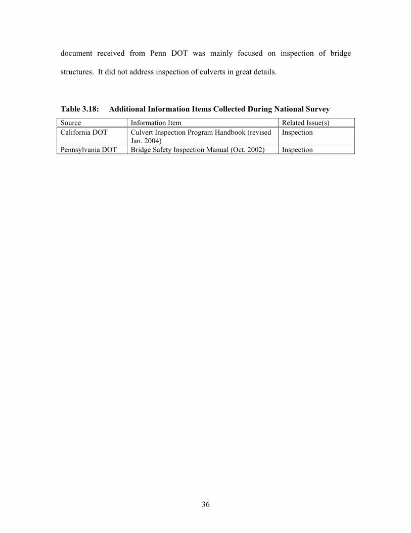
36
document received from Penn DOT was mainly focused on inspection of bridge
structures. It did not address inspection of culverts in great details.
Table 3.18: Additional Information Items Collected During National Survey
Source Information Item Related Issue(s) California DOT Culvert Inspection Program Handbook (revised
Jan. 2004) Inspection
Pennsylvania DOT Bridge Safety Inspection Manual (Oct. 2002) Inspection

37
CHAPTER 4: CULVERT MANAGEMENT PROGRAM IN OHIO
4.1 INTRODUCTION
ODOT has been making efforts to develop an effective culvert management
program over the years. ODOT published the Culvert Inspection Manual in 1990 (ODOT
1990), which was aimed at providing a tool for a periodic inspection and rating of
culverts. The manual was prepared with guidance given by previous ODOT and FHWA
publications and presented relatively detailed numerical rating systems for corrugated
metal culverts, concrete culverts, and masonry culverts. The numerical systems were
basically a set of visual rating systems in the scale of 1 to 4 which can aid inspectors to
rate the service conditions of the culverts with minimum subjective interpretation.
Definitions of the scale were:
1 (Good Condition) = No repair required.
2 (Fair Condition) = Minor deficiency; Item still functioning as designed.
3 (Poor Condition) = Major deficiency; Item in need of repair to continue
functioning as designed.
4 (Critical Condition) = Item no longer functioning as designed.
There are four main problems that can be identified with the 1990 manual. First,
the manual did not present any numerical rating systems for headwalls/wingwalls,
roadway surface, and embankment slopes. Second, the scale of 1 to 4 was not high-
resolutioned enough to detect gradual deteriorations the most culverts undergo in each
decade. Third, the visual rating systems in the 1990 manual were not detailed enough
and specific enough to further eliminate subjectivity. Finally, the manual did not address

38
culverts with protective coatings and culverts manufactured from thermoplastics. ODOT
realized a need to develop an entirely new manual. In 2003, ODOT developed a more
comprehensive manual - Culvert Management Manual.
4.2 CURRENT POLICIES
In the state of Ohio, all bridges with spans 10 ft (3.1 m) or greater are required to
be inspected annually. In contrast, culverts with span from 1 to 10 ft (0.3 to 3.1 m) are to
be inspected at least once every five years. For storm sewers under pavement, frequency
of inspection is at least once every 5 years for spans greater than or equal to 3 ft (0.9 m).
This is to assure that periodic inspections take place on all culverts and storm sewers
under traveled lanes of U.S., state, and interstate state routes maintained by the ODOT.
Conducting and reporting inspections are important elements of an overall culvert
inspection program. The primary objective of the culvert inspection is to do the following
tasks:
1. Evaluate structural adequacy.
2. Rate culvert conditions.
3. Document the findings of the inspection.
4. Recommend corrective actions.
4.3 INVENTORY DATA
ODOT inventory data will include culverts of 12 inches (0.3 m) or greater in
diameter or span. The inventory will also include storm sewers 36 inches (0.9 m) or
39
greater in diameter or span that runs transversely under travel lanes. Figure 4.1 shows the
Culvert Inventory Report form (CR-87).
4.3.1 Culvert Inventory Coding
A unique culvert file number is given for each culvert consisting of the county
number, route, and culvert number. County number consists of two-digit county code
summarized in Table 4.1. The three-digit number for the route is based on the main route
with which the culvert is associated. The culvert number is a four-digit random number.
Entry class on ODOT CR-87 form depends on the culvert safety measures. Size,
length, ability to see the opposite end, and the structure history are the factors that
determine the culvert safety measures. A flow chart is provided in Figure 4.2 for
determining the entry class. Class A is a non-entry inspection which involves collecting
inventory and inspection information without entering the structure. Class B is a non-
permit required entry, arms-length inspection performed on culverts that require no
special provisions for confined space issues. Class C is an alternate entry permit required
arms-length inspection performed on culvert that require an alternate entry procedure to
be followed. One requirement for Class C is that the culvert does not have a known
history of atmospheric or physical hazards. Class D is an entry permit required inspection
performed on culvert that require the full use and implementation of permit required
confined space entry procedures.

40
STATE OF OHIO DEPARTMENT OF TRANSPORTATION CULVERT INVENTORY REPORT
CR-87 12-03
CULVERT FILE NUMBER 1. Entry Class
LOCATION AND ROUTE INFORMATION
2. District 3. County
4. Route 5. Straight Line Mileage 6. Latitude 7. Longitude
8. Road ID 9. Maintenance Responsibility
10. Feature Intersection
CULVERT 11. Year built 12. Number of Cells 13. Shape 14. Material 15. Span (in.) 16. Rise (in.) 17. Length (ft.) 18. Gage (no.) / Wall Thickness (in.)
19. Gage (no.) / Wall Thickness (in.) 20. Type of Protection
21. Slope of Pipe (%) 22. Skew (degrees)
23. Inlet End Treatment 24. Outlet End Treatment
25. Maximum Height of Cover (ft.) 26. Modification Type
27. Year Modified 28. Modification Material 29. Modification Size (in.) EXTENSION - INLET
30. Year Extended 31. Shape
32. Material 33. Span (in.)
34. Rise (in.) 35. Gage (no.) / Wall Thickness (in.)
36. Extension Length (ft.)
EXTENSION - OUTLET
37. Year Extended 38. Shape
39. Material 40. Span (in.)
41. Rise (in.) 42. Gage (no.)/Wall Thickness (in.) 43. Extension Length (ft.) HYDROLOGY / HYDRAULICS
44. Drainage Area (acres) 45. Design Discharge (c.f.s.)
46. Abrasive Conditions 47. pH
48. Channel Protection (Inlet) 49. Channel Protection (Outlet)
COMMENTS:
INVENTORIED BY: ____ DATE: __________
___
Figure 4.1: ODOT CR-87 Form
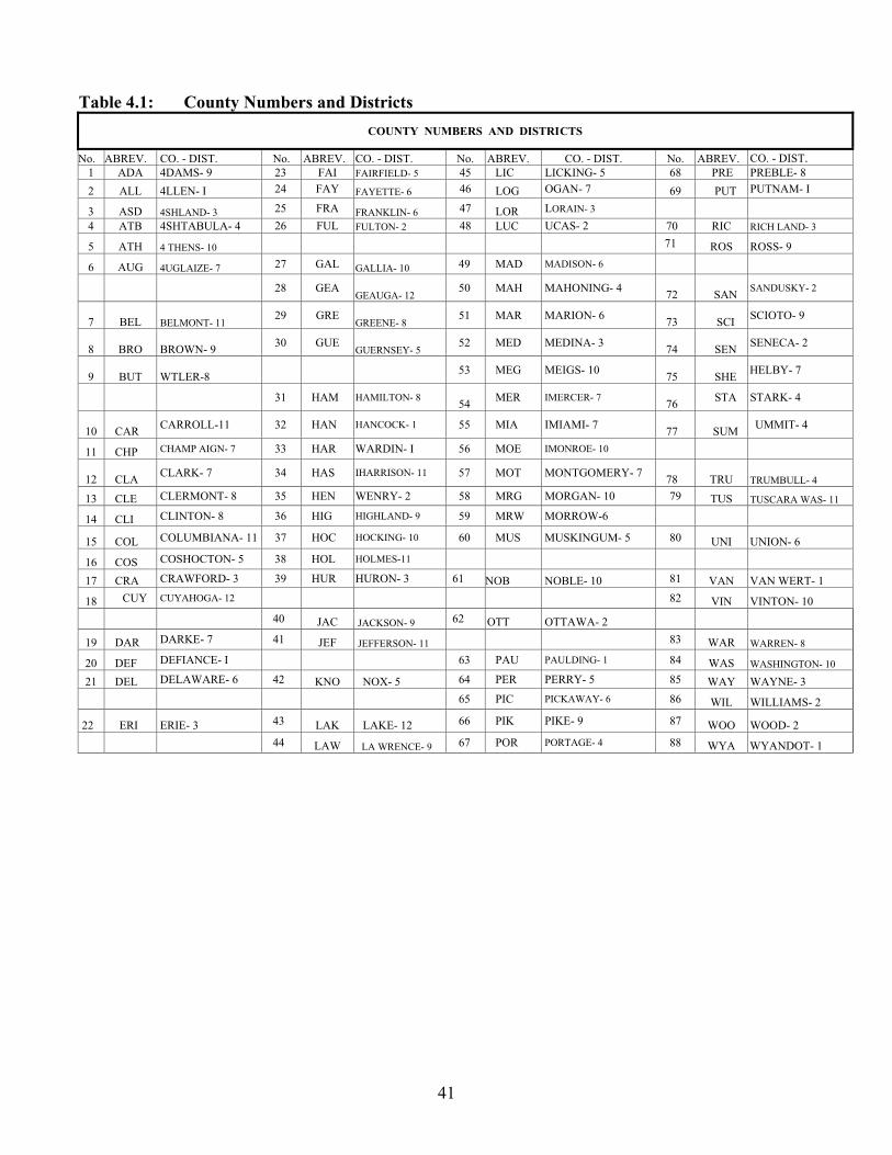
41
Table 4.1: County Numbers and Districts
COUNTY NUMBERS AND DISTRICTS
No. ABREV. CO. - DIST. No. ABREV. CO. - DIST. No. ABREV. CO. - DIST. No. ABREV. CO. - DIST.1 ADA 4DAMS- 9 23 FAI FAIRFIELD- 5 45 LIC LICKING- 5 68 PRE PREBLE- 8
2 ALL 4LLEN- I 24 FAY FAYETTE- 6 46 LOG OGAN- 7 69 PUT PUTNAM- I
3 ASD 4SHLAND- 3 25 FRA FRANKLIN- 6 47 LOR LORAIN- 3 4 ATB 4SHTABULA- 4 26 FUL FULTON- 2 48 LUC UCAS- 2 70 RIC RICH LAND- 3
5 ATH 4 THENS- 10 71 ROS ROSS- 9
6 AUG 4UGLAIZE- 7 27 GAL GALLIA- 10 49 MAD MADISON- 6 28 GEA
GEAUGA- 1250 MAH MAHONING- 4
72 SANSANDUSKY- 2
7 BEL BELMONT- 1129 GRE
GREENE- 851 MAR MARION- 6
73 SCISCIOTO- 9
8 BRO BROWN- 930 GUE
GUERNSEY- 552 MED MEDINA- 3
74 SENSENECA- 2
9 BUT WTLER-8 53 MEG MEIGS- 1075 SHE
HELBY- 7
31 HAM HAMILTON- 854
MER IMERCER- 776
STA STARK- 4
10 CARCARROLL-11 32 HAN HANCOCK- 1 55 MIA IMIAMI- 7
77 SUMUMMIT- 4
11 CHP CHAMP AIGN- 7 33 HAR WARDIN- I 56 MOE IMONROE- 10
12 CLACLARK- 7 34 HAS IHARRISON- 11 57 MOT MONTGOMERY- 7
78 TRU TRUMBULL- 4
13 CLE CLERMONT- 8 35 HEN WENRY- 2 58 MRG MORGAN- 10 79 TUS TUSCARA WAS- 11
14 CLI CLINTON- 8 36 HIG HIGHLAND- 9 59 MRW MORROW-6 15 COL COLUMBIANA- 11 37 HOC HOCKING- 10 60 MUS MUSKINGUM- 5 80 UNI UNION- 6
16 COS COSHOCTON- 5 38 HOL HOLMES-11 17 CRA CRAWFORD- 3 39 HUR HURON- 3 61 NOB NOBLE- 10 81 VAN VAN WERT- 1
18 CUY CUYAHOGA- 12 82 VIN VINTON- 10
40 JAC JACKSON- 9 62 OTT OTTAWA- 2 19 DAR DARKE- 7 41 JEF JEFFERSON- 11 83 WAR WARREN- 8
20 DEF DEFIANCE- I 63 PAU PAULDING- 1 84 WAS WASHINGTON- 10
21 DEL DELAWARE- 6 42 KNO NOX- 5 64 PER PERRY- 5 85 WAY WAYNE- 3
65 PIC PICKAWAY- 6 86 WIL WILLIAMS- 2
22 ERI ERIE- 3 43 LAK LAKE- 12 66 PIK PIKE- 9 87 WOO WOOD- 2
44 LAW LA WRENCE- 9 67 POR PORTAGE- 4 88 WYA WYANDOT- 1

42
* Class A (Non-entry Inspection) may be used on any culvert where a good view of the entire barrel may be obtained from the culvert ends.
Figure 4.2: Culvert Entry Class Flow Chart
4.3.2 Location and Route Information
Location and route information on ODOT CR-87 form include:
1. District: two-digit ODOT district number in which the culvert is located.
2. County: three-letter county abbreviation as shown in Table 4.1.
3. Route: two- or three-digit route number with which the culvert is associated.
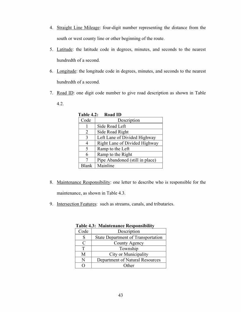
43
4. Straight Line Mileage: four-digit number representing the distance from the
south or west county line or other beginning of the route.
5. Latitude: the latitude code in degrees, minutes, and seconds to the nearest
hundredth of a second.
6. Longitude: the longitude code in degrees, minutes, and seconds to the nearest
hundredth of a second.
7. Road ID: one digit code number to give road description as shown in Table
4.2.
Table 4.2: Road ID Code Description
1 Side Road Left 2 Side Road Right 3 Left Lane of Divided Highway 4 Right Lane of Divided Highway 5 Ramp to the Left 6 Ramp to the Right 7 Pipe Abandoned (still in place)
Blank Mainline
8. Maintenance Responsibility: one letter to describe who is responsible for the
maintenance, as shown in Table 4.3.
9. Intersection Features: such as streams, canals, and tributaries.
Table 4.3: Maintenance Responsibility Code Description
S State Department of Transportation C County Agency T Township M City or Municipality N Department of Natural Resources O Other
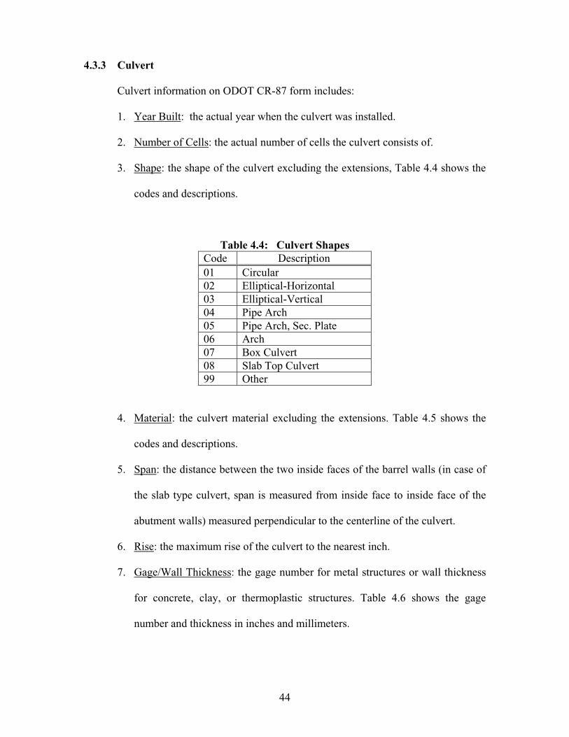
44
4.3.3 Culvert
Culvert information on ODOT CR-87 form includes:
1. Year Built: the actual year when the culvert was installed.
2. Number of Cells: the actual number of cells the culvert consists of.
3. Shape: the shape of the culvert excluding the extensions, Table 4.4 shows the
codes and descriptions.
Table 4.4: Culvert Shapes Code Description 01 Circular 02 Elliptical-Horizontal 03 Elliptical-Vertical 04 Pipe Arch 05 Pipe Arch, Sec. Plate 06 Arch 07 Box Culvert 08 Slab Top Culvert 99 Other
4. Material: the culvert material excluding the extensions. Table 4.5 shows the
codes and descriptions.
5. Span: the distance between the two inside faces of the barrel walls (in case of
the slab type culvert, span is measured from inside face to inside face of the
abutment walls) measured perpendicular to the centerline of the culvert.
6. Rise: the maximum rise of the culvert to the nearest inch.
7. Gage/Wall Thickness: the gage number for metal structures or wall thickness
for concrete, clay, or thermoplastic structures. Table 4.6 shows the gage
number and thickness in inches and millimeters.
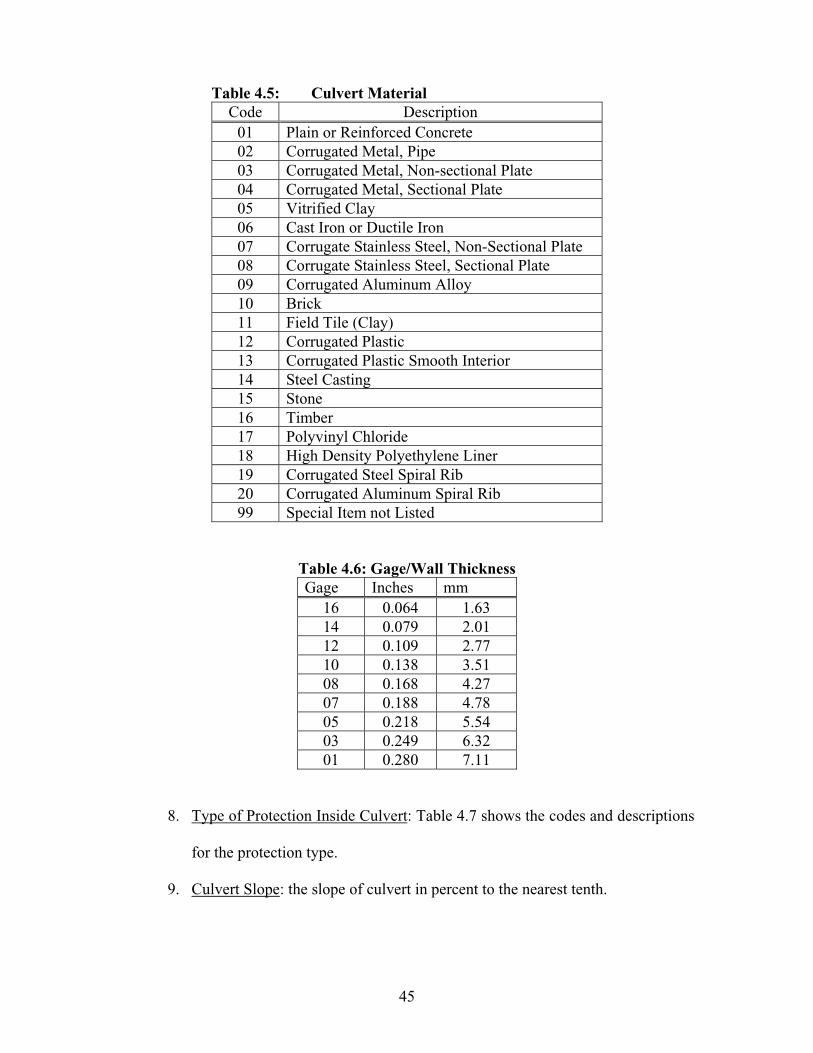
45
Table 4.5: Culvert Material Code Description
01 Plain or Reinforced Concrete 02 Corrugated Metal, Pipe 03 Corrugated Metal, Non-sectional Plate 04 Corrugated Metal, Sectional Plate 05 Vitrified Clay 06 Cast Iron or Ductile Iron 07 Corrugate Stainless Steel, Non-Sectional Plate 08 Corrugate Stainless Steel, Sectional Plate 09 Corrugated Aluminum Alloy 10 Brick 11 Field Tile (Clay) 12 Corrugated Plastic 13 Corrugated Plastic Smooth Interior 14 Steel Casting 15 Stone 16 Timber 17 Polyvinyl Chloride 18 High Density Polyethylene Liner 19 Corrugated Steel Spiral Rib 20 Corrugated Aluminum Spiral Rib 99 Special Item not Listed
Table 4.6: Gage/Wall Thickness Gage Inches mm
16 0.064 1.63 14 0.079 2.01 12 0.109 2.77 10 0.138 3.51 08 0.168 4.27 07 0.188 4.78 05 0.218 5.54 03 0.249 6.32 01 0.280 7.11
8. Type of Protection Inside Culvert: Table 4.7 shows the codes and descriptions
for the protection type.
9. Culvert Slope: the slope of culvert in percent to the nearest tenth.
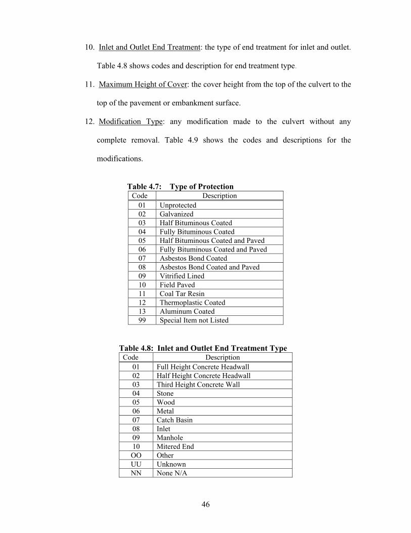
46
10. Inlet and Outlet End Treatment: the type of end treatment for inlet and outlet.
Table 4.8 shows codes and description for end treatment type.
11. Maximum Height of Cover: the cover height from the top of the culvert to the
top of the pavement or embankment surface.
12. Modification Type: any modification made to the culvert without any
complete removal. Table 4.9 shows the codes and descriptions for the
modifications.
Table 4.7: Type of ProtectionCode Description
01 Unprotected 02 Galvanized 03 Half Bituminous Coated 04 Fully Bituminous Coated 05 Half Bituminous Coated and Paved 06 Fully Bituminous Coated and Paved 07 Asbestos Bond Coated 08 Asbestos Bond Coated and Paved 09 Vitrified Lined 10 Field Paved 11 Coal Tar Resin 12 Thermoplastic Coated 13 Aluminum Coated 99 Special Item not Listed
Table 4.8: Inlet and Outlet End Treatment Type Code Description
01 Full Height Concrete Headwall 02 Half Height Concrete Headwall 03 Third Height Concrete Wall 04 Stone 05 Wood 06 Metal 07 Catch Basin 08 Inlet 09 Manhole 10 Mitered End OO Other UU Unknown NN None N/A

47
Table 4.9: Modification Type Code Description
R Relining original conduit. P Field Paving of the conduit invert.
SReplacing or adding sections or structural plates (within original length).
BInstalling internal bands at joints or other areas.
O Other modifications.
13. Year Modified: the year of major repair or rehabilitation of the culvert.
14. Modification Material: Table 4.10 shows the code and description for each
material modification.
Table 4.10: Modification Material Code Description
01 Plain or Reinforced Concrete 02 Corrugated Steel Conduit 03 Corrugated Steel Structural Plate 04 Corrugated Steel Spiral Rib 05 Corrugated Steel Flanged Liner Plates 06 Corrugated Aluminum Alloy Conduit 07 Corrugated Aluminum Alloy Structural Plate 08 Corrugated Aluminum Spiral Rib 09 Thermoplastic Pipe Liner (PVC or HDPE) 10 Folded PVC Liner 11 Cured in Place PVC Liner 12 Steel Casing Pipe 99 Other
15. Modification Size: this measurement will vary with the type of modification
performed. Table 4.11 shows the modification type and measurements.

48
Table 4.11: Modification Size Modification Type Measurement
Relining original conduit
Internal Diameter
Field Paving of the conduit invert
Thickness of paving
Replacing or adding sections or structural plates
Gage of Plates
Installing internal bands at joint or other areas
Internal diameter at bands
4.3.4 Extension-Inlet and Extension-Outlet
Those two sections in the ODOT CR-87 form require culvert shape, material, rise
(in.), span (in.), extension length, gage (no.)/wall thickness (in.), and year of extension.
4.3.5 Hydrology / Hydraulics
Hydrology/hydraulics information in ODOT CR-87 form includes:
1. Drainage Area: total area draining through the culvert in acres.
2. Design Discharge: culvert design flow rate in ft3/sec.
3. Abrasive Condition, the presence of granular material accompanied with
stream gradient or sufficient flow to cause movement of the granular
material in the streambed. Codes are Y and N for abrasive and
nonabrasive condition, respectively.
4. pH: the value of water pH at the inlet of the culvert to the nearest tenth.
5. Channel Protection (Inlet and Outlet): channel protection placed by design
or for maintenance purposes. Table 4.12 shows the code and description
for each type of channel protection.
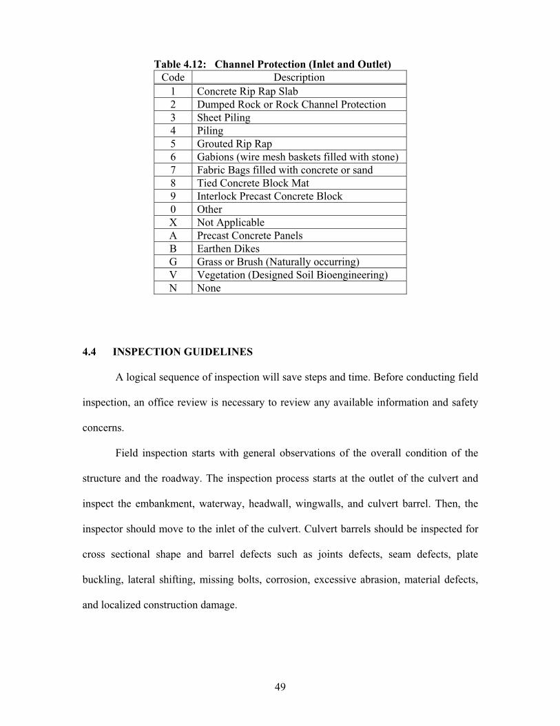
49
Table 4.12: Channel Protection (Inlet and Outlet) Code Description
1 Concrete Rip Rap Slab 2 Dumped Rock or Rock Channel Protection 3 Sheet Piling 4 Piling 5 Grouted Rip Rap 6 Gabions (wire mesh baskets filled with stone) 7 Fabric Bags filled with concrete or sand 8 Tied Concrete Block Mat 9 Interlock Precast Concrete Block 0 Other X Not Applicable A Precast Concrete Panels B Earthen Dikes G Grass or Brush (Naturally occurring) V Vegetation (Designed Soil Bioengineering) N None
4.4 INSPECTION GUIDELINES
A logical sequence of inspection will save steps and time. Before conducting field
inspection, an office review is necessary to review any available information and safety
concerns.
Field inspection starts with general observations of the overall condition of the
structure and the roadway. The inspection process starts at the outlet of the culvert and
inspect the embankment, waterway, headwall, wingwalls, and culvert barrel. Then, the
inspector should move to the inlet of the culvert. Culvert barrels should be inspected for
cross sectional shape and barrel defects such as joints defects, seam defects, plate
buckling, lateral shifting, missing bolts, corrosion, excessive abrasion, material defects,
and localized construction damage.

50
Stationing and orientation in sectional culverts are referenced by using culvert
joints as stations. Stationing should start with number one at the outlet and increase
toward the inlet. Location of points on circular cross section is referenced as hour on a
clock. The clock should be oriented looking upstream. On the structural plate corrugated
metal culverts, points are referenced to bolted circumferential and longitudinal seams.
4.5 CULVERT RATING SYSTEMS
Culvert inspection guidelines provide a starting point for culvert evaluation. The
inspecting team needs to use their judgment in assigning the appropriate numerical rating.
Inspector should select the lowest rating which best describes either the shape condition
or the barrel condition. The following sections in this chapter present the sixteen coded
items in the ODOT Culvert Inspection Report form (CR-86), shown in Figure 4.3
4.5.1 General Conditions of Culvert Material
This item evaluates culvert for:
1. Deterioration: this is the ability of the material to resist corrosion and
abrasion. Corrosion is the destruction of culvert material by chemical action.
Commonly, corrosion attacks metal culverts, or the reinforcement in concrete
culverts, as the process of metals returning to their native state of oxides or
salts. Similar processes can occur to the cement in concrete culvert if
subjected to highly alkaline soils or other extremely harsh environments.
Abrasion is the gradual wearing away of the culvert wall due to the
impingement of bedload and suspended material. Corrosion and abrasion can
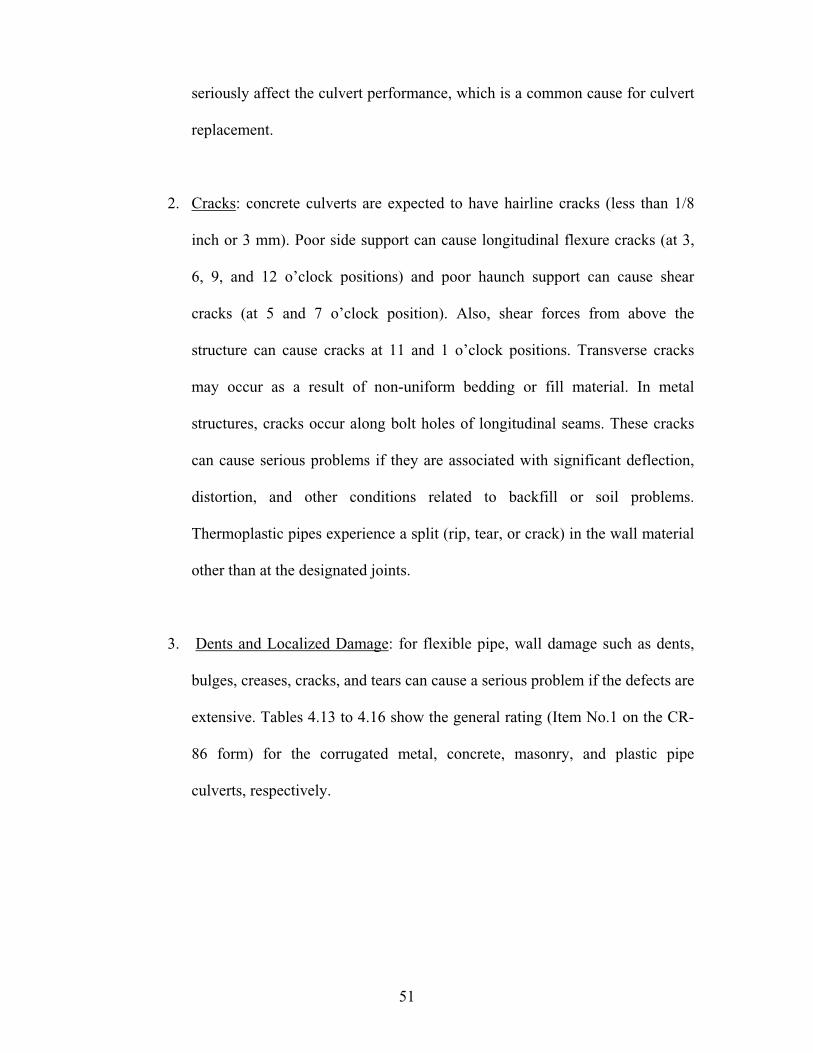
51
seriously affect the culvert performance, which is a common cause for culvert
replacement.
2. Cracks: concrete culverts are expected to have hairline cracks (less than 1/8
inch or 3 mm). Poor side support can cause longitudinal flexure cracks (at 3,
6, 9, and 12 o’clock positions) and poor haunch support can cause shear
cracks (at 5 and 7 o’clock position). Also, shear forces from above the
structure can cause cracks at 11 and 1 o’clock positions. Transverse cracks
may occur as a result of non-uniform bedding or fill material. In metal
structures, cracks occur along bolt holes of longitudinal seams. These cracks
can cause serious problems if they are associated with significant deflection,
distortion, and other conditions related to backfill or soil problems.
Thermoplastic pipes experience a split (rip, tear, or crack) in the wall material
other than at the designated joints.
3. Dents and Localized Damage: for flexible pipe, wall damage such as dents,
bulges, creases, cracks, and tears can cause a serious problem if the defects are
extensive. Tables 4.13 to 4.16 show the general rating (Item No.1 on the CR-
86 form) for the corrugated metal, concrete, masonry, and plastic pipe
culverts, respectively.

52
STATE OF OHIO DEPARTMENT OF TRANSPORTATION CULVERT INSPECTION REPORT
CR-86 12-03
CULVERT FILE NUMBER CULVERT NUMBER _______ _______ _______ ______ YEAR BUILT____________ CO ROUTE SLM ID
DISTRICT_________SHAPE__ MATERIAL LENGTH__
MAX. HEIGHT OF COVER_____ FEATURE INT.
LATITUDE LONGITUDE ___
ENTRY CLASS NUMBER of CELLS
CULVERT
1. General 2. Culvert Alignment
3. Shape 4. Seams or Joints
5. Slab 6. Abutments
7. Headwalls 8. End Structure
CHANNEL
9. Channel Alignment 10. Protection
11. Culvert Waterway Blockage 12. Scour
APPROACHES
13. Pavement 14. Guardrail
15. Embankment
16. Level of Inspection GENERAL APPRAISAL& OPERATIONAL STATUS
RECOMMENDED REPAIR CODE(S): COMMENTS: _______________________________________________________________
COMMENTS: _________________________________________________________________________________________________
_______________________________________________________________________________________________________________
_______________________________________________________________________________________________________________
_______________________________________________________________________________________________________________
_______________________________________________________________________________________________________________
INSPECTED BY:___________________ DATE: _________________ REVIEWED BY:___________________ DATE: _____________
Figure 4.3: ODOT CR-86 Form

53
Table 4.13: General-Corrugated Metal Culvert Code Category Description
9 Excellent New condition; galvanizing intact; no corrosion.
8 Very Good Discoloration of surface; galvanizing partially gone along invert but no layer of rust.
7 Good
Discoloration of surface, galvanizing gone along invert but no layers of rust. Minor pinholes (with an area less than 3 square inches per square foot) in pipe material located at ends of pipe (length not to exceed 4 feet and not located beneath roadway).
6 Satisfactory
Galvanizing gone along invert with layers of rust. Sporadic pitting of invert. Minor pinholes (with an area less than 6 square inches per square foot, 4%) in pipe material located at ends of pipe (length not to exceed 4 feet and not located beneath roadway).
5 Fair Heavy rust and scale. Pinholes (with an area less than 15 square inches per square foot, 10%) throughout pipe material. Section loss and perorations at ends. Holes in metal at end in invert and not located under roadway.
4 Poor
Extensive heavy rust; thick and scaling rust throughout pipe; deep pitting; perforations throughout invert with an area less than 30 square inches per square foot, 20%. Overall thin metal, which allows for an easy puncture with chipping hammer.
3 Serious
Extensive heavy rust; thick and scaling rust throughout pipe; deep pitting. Perforations throughout invert with an area less than 36 square inches per square foot, 25%. Overall thin metal, which allows for an easy puncture with chipping hammer. End section corroded away.
2 Critical Perforations throughout invert with an area greater than 36 square inches per square foot, 25%.
1 Imminent Pipe partially collapsed.
0 Failed Total failure of pipe.

54
Table 4.14: General-Concrete Culvert Code Category Description
9 Excellent New condition, superficial and isolated damage from construction.
8 Very Good Hairline cracking without rust staining or delaminations; surface in good condition; isolated damage form construction.
7 Good
Hairline cracking. No single crack greater than 1/16 inch without rust staining parallel to the direction of traffic; light scaling on less than 10% of exposed area less than 1/8 inch deep. Delaminated/ spalled area less than 1% of surface area.
[Note] Cast-in-place box culverts may have a single large crack (less than 3/16 inch) n each surface parallel to the direction of traffic.
6 Satisfactory
Hairline map cracking combined with molted areas. Cracks less than 1/8 inch parallel to traffic with minor efflorescence or minor amounts of leakage. Scaling on less than 20% of exposed area less than ¼ inches deep. Spalled areas with exposed reinforcing less than 5%. Additional delaminated/ spalled areas les than 5% of surface area.
5 Fair
Map cracking. Cracks less than 1/8 inch parallel to traffic, less than 1/16 inch transverse to traffic with efflorescence and/or rust stain, leakage and molted areas. Scaling on less than 30% of exposed area less than 3/16 inch deep. Spalled areas with exposed reinforcing less than 10%. Total delaminated/ spalled areas less than 15% of surface area.
4 Poor
Transverse cracks open greater than 1/8 inch with efflorescence and rust staining. Spalling at numerous locations; extensive surface scaling on invert greater than ½ inch. Extensive cracking with cracks open more than 1/8 inch with efflorescence; spalling has caused exposure of heavily corroded reinforcing steel on bottom or top slab; extensive surface scaling on invert greater than ¾ inch. (approximately 50% of culvert is affected)
3 Serious
Extensive cracking with spalling, delaminations, and slight differential movement; scaling has exposed all surfaces of the reinforcing steel in bottom to top slab or invert (approximately all exposed surface are 50% loss of wall thickness at invert; concrete very soft
2 Critical
Full depth holes. Extensive cracking greater than ½ inch. Spalled areas with exposed reinforcing greater than 25%. Total delaminated, spalled, and punky concrete areas are greater than 50% of surface area. Reinforcing steel bars have extensive section loss and perimeter of bar in completely exposed. ( Several bars in a row)
1Imminent
Failure Culvert partially collapsed or collapse in imminent
0 Failed The culvert in collapsed
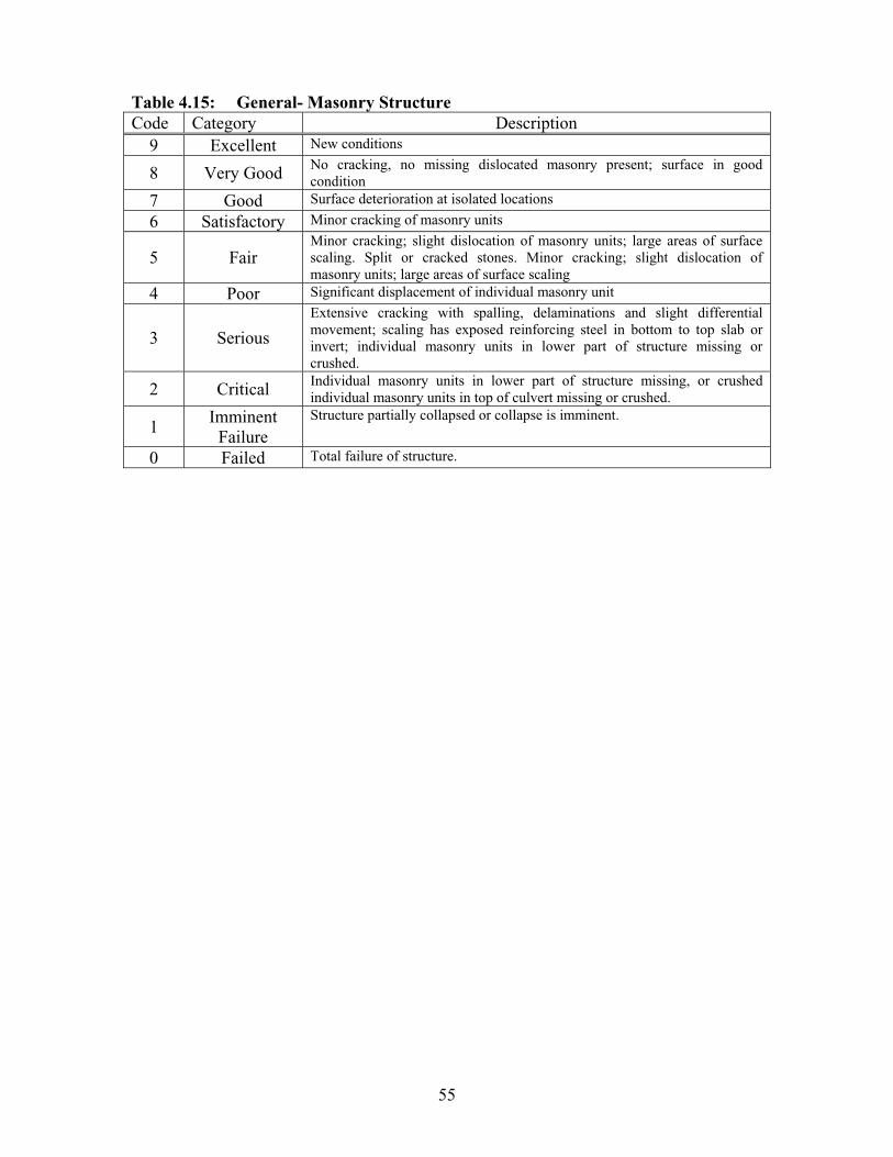
55
Table 4.15: General- Masonry Structure Code Category Description
9 Excellent New conditions
8 Very Good No cracking, no missing dislocated masonry present; surface in good condition
7 Good Surface deterioration at isolated locations
6 Satisfactory Minor cracking of masonry units
5 Fair Minor cracking; slight dislocation of masonry units; large areas of surface scaling. Split or cracked stones. Minor cracking; slight dislocation of masonry units; large areas of surface scaling
4 Poor Significant displacement of individual masonry unit
3 Serious
Extensive cracking with spalling, delaminations and slight differential movement; scaling has exposed reinforcing steel in bottom to top slab or invert; individual masonry units in lower part of structure missing or crushed.
2 Critical Individual masonry units in lower part of structure missing, or crushed individual masonry units in top of culvert missing or crushed.
1Imminent
Failure Structure partially collapsed or collapse is imminent.
0 Failed Total failure of structure.
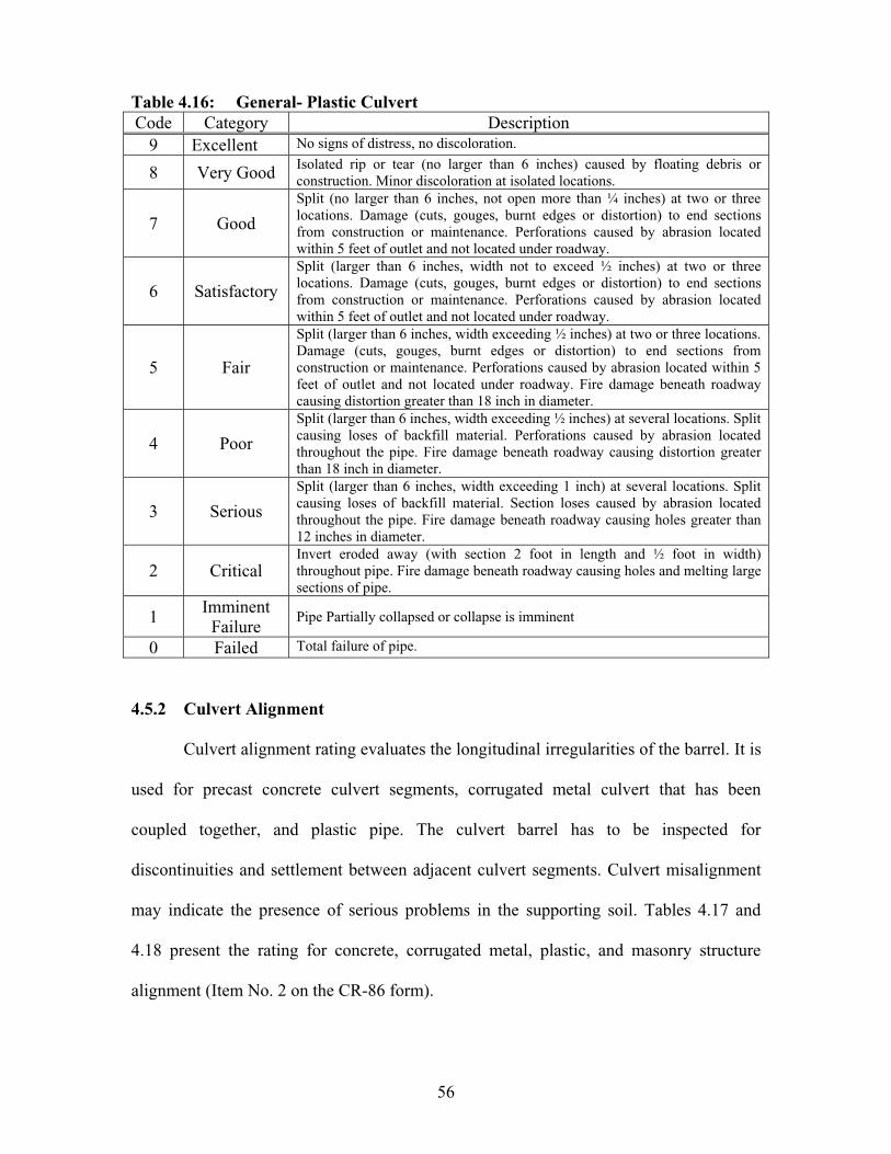
56
Table 4.16: General- Plastic Culvert Code Category Description
9 Excellent No signs of distress, no discoloration.
8 Very Good Isolated rip or tear (no larger than 6 inches) caused by floating debris or construction. Minor discoloration at isolated locations.
7 Good
Split (no larger than 6 inches, not open more than ¼ inches) at two or three locations. Damage (cuts, gouges, burnt edges or distortion) to end sections from construction or maintenance. Perforations caused by abrasion located within 5 feet of outlet and not located under roadway.
6 Satisfactory
Split (larger than 6 inches, width not to exceed ½ inches) at two or three locations. Damage (cuts, gouges, burnt edges or distortion) to end sections from construction or maintenance. Perforations caused by abrasion located within 5 feet of outlet and not located under roadway.
5 Fair
Split (larger than 6 inches, width exceeding ½ inches) at two or three locations. Damage (cuts, gouges, burnt edges or distortion) to end sections from construction or maintenance. Perforations caused by abrasion located within 5 feet of outlet and not located under roadway. Fire damage beneath roadway causing distortion greater than 18 inch in diameter.
4 Poor
Split (larger than 6 inches, width exceeding ½ inches) at several locations. Split causing loses of backfill material. Perforations caused by abrasion located throughout the pipe. Fire damage beneath roadway causing distortion greater than 18 inch in diameter.
3 Serious
Split (larger than 6 inches, width exceeding 1 inch) at several locations. Split causing loses of backfill material. Section loses caused by abrasion located throughout the pipe. Fire damage beneath roadway causing holes greater than 12 inches in diameter.
2 Critical Invert eroded away (with section 2 foot in length and ½ foot in width) throughout pipe. Fire damage beneath roadway causing holes and melting large sections of pipe.
1Imminent
Failure Pipe Partially collapsed or collapse is imminent
0 Failed Total failure of pipe.
4.5.2 Culvert Alignment
Culvert alignment rating evaluates the longitudinal irregularities of the barrel. It is
used for precast concrete culvert segments, corrugated metal culvert that has been
coupled together, and plastic pipe. The culvert barrel has to be inspected for
discontinuities and settlement between adjacent culvert segments. Culvert misalignment
may indicate the presence of serious problems in the supporting soil. Tables 4.17 and
4.18 present the rating for concrete, corrugated metal, plastic, and masonry structure
alignment (Item No. 2 on the CR-86 form).
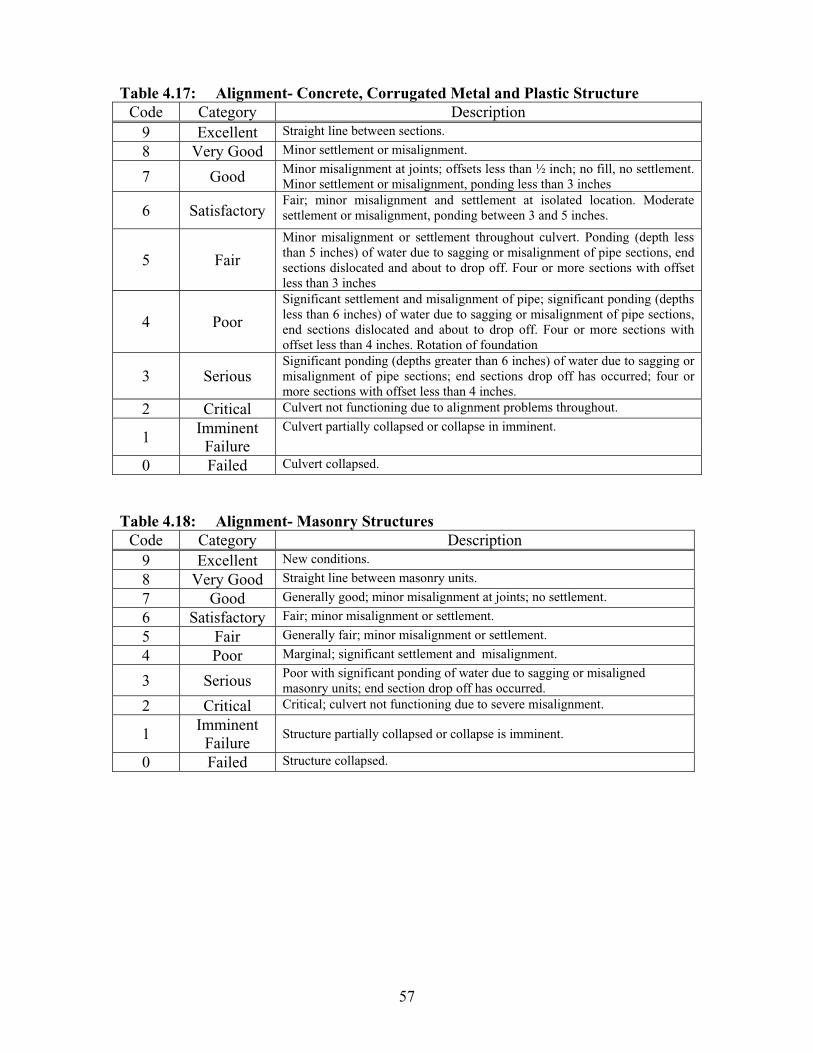
57
Table 4.17: Alignment- Concrete, Corrugated Metal and Plastic Structure Code Category Description
9 Excellent Straight line between sections.
8 Very Good Minor settlement or misalignment.
7 Good Minor misalignment at joints; offsets less than ½ inch; no fill, no settlement. Minor settlement or misalignment, ponding less than 3 inches
6 Satisfactory Fair; minor misalignment and settlement at isolated location. Moderate settlement or misalignment, ponding between 3 and 5 inches.
5 Fair
Minor misalignment or settlement throughout culvert. Ponding (depth less than 5 inches) of water due to sagging or misalignment of pipe sections, end sections dislocated and about to drop off. Four or more sections with offset less than 3 inches
4 Poor
Significant settlement and misalignment of pipe; significant ponding (depths less than 6 inches) of water due to sagging or misalignment of pipe sections, end sections dislocated and about to drop off. Four or more sections with offset less than 4 inches. Rotation of foundation
3 Serious Significant ponding (depths greater than 6 inches) of water due to sagging or misalignment of pipe sections; end sections drop off has occurred; four or more sections with offset less than 4 inches.
2 Critical Culvert not functioning due to alignment problems throughout.
1Imminent
Failure Culvert partially collapsed or collapse in imminent.
0 Failed Culvert collapsed.
Table 4.18: Alignment- Masonry Structures Code Category Description
9 Excellent New conditions.
8 Very Good Straight line between masonry units.
7 Good Generally good; minor misalignment at joints; no settlement.
6 Satisfactory Fair; minor misalignment or settlement.
5 Fair Generally fair; minor misalignment or settlement.
4 Poor Marginal; significant settlement and misalignment.
3 Serious Poor with significant ponding of water due to sagging or misaligned masonry units; end section drop off has occurred.
2 Critical Critical; culvert not functioning due to severe misalignment.
1Imminent
Failure Structure partially collapsed or collapse is imminent.
0 Failed Structure collapsed.
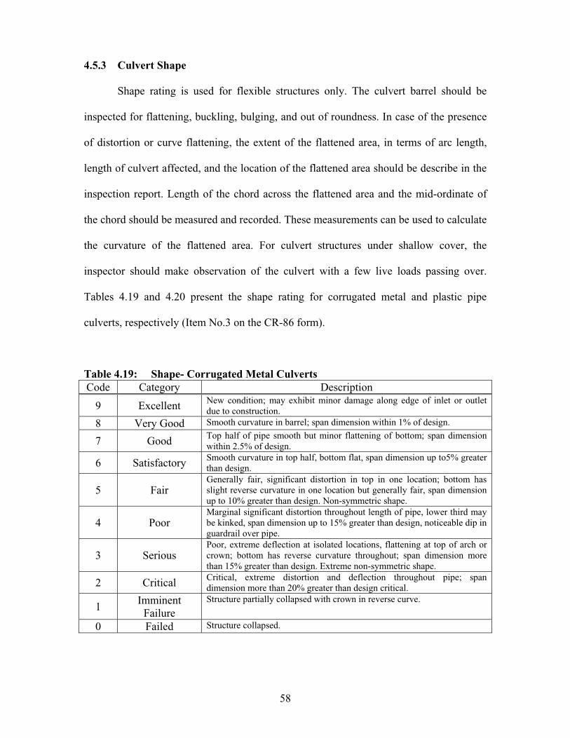
58
4.5.3 Culvert Shape
Shape rating is used for flexible structures only. The culvert barrel should be
inspected for flattening, buckling, bulging, and out of roundness. In case of the presence
of distortion or curve flattening, the extent of the flattened area, in terms of arc length,
length of culvert affected, and the location of the flattened area should be describe in the
inspection report. Length of the chord across the flattened area and the mid-ordinate of
the chord should be measured and recorded. These measurements can be used to calculate
the curvature of the flattened area. For culvert structures under shallow cover, the
inspector should make observation of the culvert with a few live loads passing over.
Tables 4.19 and 4.20 present the shape rating for corrugated metal and plastic pipe
culverts, respectively (Item No.3 on the CR-86 form).
Table 4.19: Shape- Corrugated Metal Culverts Code Category Description
9 Excellent New condition; may exhibit minor damage along edge of inlet or outlet due to construction.
8 Very Good Smooth curvature in barrel; span dimension within 1% of design.
7 Good Top half of pipe smooth but minor flattening of bottom; span dimension within 2.5% of design.
6 Satisfactory Smooth curvature in top half, bottom flat, span dimension up to5% greater than design.
5 Fair Generally fair, significant distortion in top in one location; bottom has slight reverse curvature in one location but generally fair, span dimension up to 10% greater than design. Non-symmetric shape.
4 Poor Marginal significant distortion throughout length of pipe, lower third may be kinked, span dimension up to 15% greater than design, noticeable dip in guardrail over pipe.
3 Serious Poor, extreme deflection at isolated locations, flattening at top of arch or crown; bottom has reverse curvature throughout; span dimension more than 15% greater than design. Extreme non-symmetric shape.
2 Critical Critical, extreme distortion and deflection throughout pipe; span dimension more than 20% greater than design critical.
1Imminent
Failure Structure partially collapsed with crown in reverse curve.
0 Failed Structure collapsed.

59
Table 4.20: Shape- Plastic Pipe Culvert Code Category Description
9 Excellent Smooth wall, deflection less than 2% from the original shape.
8 Very Good Smooth wall, deflection less than 5% from original shape.
7 Good Relatively smooth wall, deflection less than 5% from original shape.
6 Satisfactory Minor dimpling appearing at isolated small area (less than 1/16 of circumference area and 1 foot in length). Dimpling less than ¼ inch deep. Pipe deflection less than 10% from original.
5 Fair Minor dimpling appearing over 1/16 to 1/8 of circumference area and 2 feet in length. Dimples between ¼ and ½ inch deep. Pipe deflection less than 12.5% from original shape.
4 Poor Wall crushing or hinging occurring with lengths less than 3 feet. Pipe deflection less than 15% from original shape.
3 Serious
Wall crushing or hinging occurring with lengths less than 3 feet. Moderate degree of dimpling appearing. Dimples more than ½ inch deep. Wall tearing/ cracking in the buckled region. Pipe deflection less than 20% from original shape.
2 Critical
Wall crushing or hinging occurring over the majority of the length of pipe under the roadway. Moderate degree of dimpling appearing. Dimples more than ½ deep. Wall tearing/ cracking in the buckled region. Pipe deflection greater than 20% from original shape. Sever dimpling accompanied with wall splits.
1Imminent
Failure Pipe partially collapsed or collapsed is imminent.
0 Failed Total failure of pipe.
4.5.4 Seams and Joints
Seams and joints rating include joints opening, seepage at joints, and surface
sinkholes over the culvert. Indications of backfill infiltration and water exfiltration are the
main factors to look for in joints and seams inspection. Seepage along the outside barrel
can remove the supporting material. This process is called “piping.” Piping can also
occur through open joints. Piping can be controlled by reducing the amount and velocity
of water seeping along the outside barrel of the culvert. This requires watertight joint and
anti-seep collars in some cases. Defects in seams in structural plate culverts include loose
fasteners, cocked and cusped seams, seam cracking, and bolt tipping. Tables 4.21 and
4.22 present the seams and joints rating for corrugated metal, concrete, plastic, and
masonry culverts, respectively (Item No. 4 on the CR-86 form).

60
Table 4.21: Seams or Joints-Corrugated Metal, Multi-Plate Code Category Description
9 Excellent Minor amounts of efflorescence or staining.
8 Very Good Light surface rust on bolts due to loss of galvanizing, efflorescence staining.
7 Good Metal has cracking on each side of the bolt hole less than 3 in a seam section. Minor seam openings less than 1/8 inch. Potential for backfill infiltration. More than 2 missing bolt in a row. Rust scale around bolts.
6 Satisfactory Evidence of backfill infiltration through seams
5 Fair Moderate cracking at bolt holes along a seam in one section. Backfill being lost through seam causing slight deflection. More than 6 missing bolt in a row or 20% along the total seam.
4 Poor Major cracking of seam near crown. Infiltration of backfill causing major deflection. Partial cocked and cusped seams. 10% section loss to bolt heads along seams.
3 Serious Longitudinal cocked and cusped seams and / or metal has 3 inch crack on each side of the bolt hole run total length of culvert. Missing or tipping bolts.
2 Critical Seam cracked from bolt to bolt; significant amounts of backfill infiltration.
1Imminent
Failure Pipe Partially collapsed or collapse is imminent.
0 Failed Total failure of pipe.

61
Table 4.22: Seams or Joints- Corrugated Metal, Concrete, Plastic Pipe, and Masonry Culverts
Code Category Description 9 Excellent Straight line between sections.
8 Very Good No settlement or misalignment; Tight with no apparent defects.
7 Good Minor misalignment at joints; offsets less than ½ inch. Possible minor infiltration of fills no settlement. Minor distress to pipe material adjacent to joint. Shallow mortar deterioration at isolated locations.
6 Satisfactory
Minor backfill infiltration due to slight opening at joints; minor cracking or spalling at joints allowing exfiltration. Dislocated end section. Extensive areas of shallow deterioration; missing mortar at isolated locations; possible infiltration or exfiltration; minor cracking.
5 Fair
Joint open and allowing backfill to infiltrate; significant cracking, spalling, buckling of pipe material. Joint offset less than 3 inches. End sections dislocated about to drop off mortar generally deteriorated, loose or missing mortar at isolated locations; infiltration staining apparent.
4 Poor
Differential movement and separation of joints; significant infiltration or exfiltration at joints. Joint offset less than 4 inches. Voids seen in fill through offset joints. End sections dropped off at inlet. Mortar severely deteriorated, significant loss of mortar, significant infiltration or exfiltration between masonry units.
3 Serious
Significant openings, dislocated joints in several locations exposing fill material with joint offsets greater than 4 inches. Infiltration or exfiltration causing misalignment of pipe and settlement or depressions in roadway. Large voids seen in fill through offset joints. Extensive areas of missing mortar, infiltration or exfiltration causing misalignment of culvert and settlement or depressions in roadway.
2 Critical Culvert not functioning due alignment problems throughout. Large voids seen in fill through offset joints.
1Imminent
Failure Pipe partially collapsed or collapse is imminent.
0 Failed Total failure of pipe.
4.5.5 Slab
Concrete slab should be inspected for cracks, scaling, leakage, deterioration,
delaminations, spalling, efflorescence, honeycombs, pop-outs, wear, collision damage,
abrasion, and reinforcing steel corrosion. Hammer and chain drags can be used to detect
delaminated areas. Table 4.23 presents the slab rating (Item No. 5 on the CR-86 form).

62
Table 4.23: Slab Code Category Description
9 Excellent No signs of distress, no discoloration.
8 Very Good Minor scaling (less than 1/8 inch deep over 5% of deck surface). Hairline cracking without rust staining or delaminations; no dampness, no leakage, no spalling. Isolated damage from construction.
7 Good
Hairline cracking w/ no single crack greater than 1/16 inch without rust staining parallel to the direction of traffic; light scaling on less than 10% of exposed area( less than 1/8 inch deep). Delaminated/ spalled area less than 1% of surface area (not including slab edges); isolated damage from construction or vehicle impact. Note: - Slab may have a single large crack (less than 3/16 inch) on bottom surface parallel to the direction traffic.
6 Satisfactory
Transverse cracks evident on bottom side (spacing 10’ t0 20’), some could be leaking. Some spalling may be present (1%-10% of total deck area). Hairline map cracking combined with molted areas. Cracks (less than 1/8 inch) parallel to the traffic with minor efflorescence or minor amounts of leakage. Scaling on less than 20% of slab area. Additional delaminated/ spalled areas less than 10% of surface area (no including slab edges).
5 Fair
Map cracking. Cracks (less than 1/8 inch parallel to traffic, less than 1/16 inch transverse to traffic) with efflorescence and/or rust stain, leakage and molted areas. Scaling on less than 30% of exposed area (less than 3/16 inch deep). Spalled areas with exposed reinforcing less than 10%. Total delaminated/spalled areas less than 20% of surface area (not including slab edges).
4 Poor
Surface patches over at least 25% of deck area. Steel plates covering full depth holes. Map cracking with dark/damp areas and efflorescence over at least 30% of deck bottom. Several transverse cracks open more than 1/8 inch with efflorescence and rust staining. Spalling at numerous locations; extensive surface scaling greater than ½ inch. Included in distress areas ( not including slab edges).
3 Serious Same as “Poor” description except: Included in distress areas reinforcing steel bars have extensive section losses (greater than 20% of original diameter) for more than 5 adjacent bars.
2 Critical
Full depth holes. Cracking and white efflorescence. Total delaminated, spalled; map cracking and punky concrete areas are greater than 50% surface area. Reinforcing steel bars have extensive section losses (greater than 30% of original diameter) for more than 10 adjacent bars. Additional dark and damp areas over at least 50% of deck.
1Imminent
Failure Slab partially collapsed or collapse is imminent.
0 Failed Total failure of slab.
4.5.6 Abutment
Abutment is a sub-structural unit located at the ends of a bridge or slab culver. It
provides end support to the culvert and retains the approach embankment. Wingwalls are
also considered part of the abutment if they are integral with the abutment. Their function
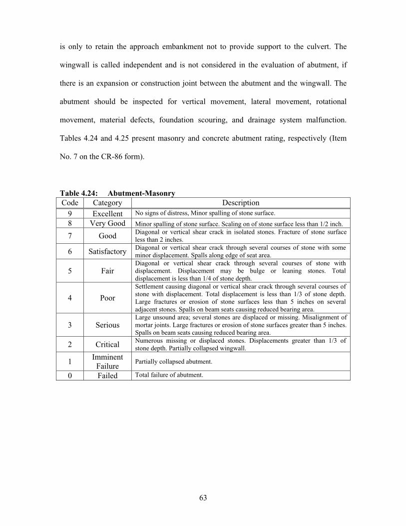
63
is only to retain the approach embankment not to provide support to the culvert. The
wingwall is called independent and is not considered in the evaluation of abutment, if
there is an expansion or construction joint between the abutment and the wingwall. The
abutment should be inspected for vertical movement, lateral movement, rotational
movement, material defects, foundation scouring, and drainage system malfunction.
Tables 4.24 and 4.25 present masonry and concrete abutment rating, respectively (Item
No. 7 on the CR-86 form).
Table 4.24: Abutment-Masonry Code Category Description
9 Excellent No signs of distress, Minor spalling of stone surface.
8 Very Good Minor spalling of stone surface. Scaling on of stone surface less than 1/2 inch.
7 Good Diagonal or vertical shear crack in isolated stones. Fracture of stone surface less than 2 inches.
6 Satisfactory Diagonal or vertical shear crack through several courses of stone with some minor displacement. Spalls along edge of seat area.
5 Fair Diagonal or vertical shear crack through several courses of stone with displacement. Displacement may be bulge or leaning stones. Total displacement is less than 1/4 of stone depth.
4 Poor
Settlement causing diagonal or vertical shear crack through several courses of stone with displacement. Total displacement is less than 1/3 of stone depth. Large fractures or erosion of stone surfaces less than 5 inches on several adjacent stones. Spalls on beam seats causing reduced bearing area.
3 Serious Large unsound area; several stones are displaced or missing. Misalignment of mortar joints. Large fractures or erosion of stone surfaces greater than 5 inches. Spalls on beam seats causing reduced bearing area.
2 Critical Numerous missing or displaced stones. Displacements greater than 1/3 of stone depth. Partially collapsed wingwall.
1Imminent
Failure Partially collapsed abutment.
0 Failed Total failure of abutment.

64
Table 4.25: Abutment-Concrete Code Category Description
9 Excellent No signs of distress, no discoloration.
8 Very Good Minor scaling (less than 1/8 inch deep over 5% of concrete surface). Hairline cracking without rust staining or delaminations no dampness, no leakage, no spalling. Isolated damage from construction.
7 Good Hairline cracking. No single crack greater than 1/16 inch without rust staining; light scaling on less than 10% or exposed area (less than 1/8 inch deep) delaminated/ spalled area less than 1 % of surface area.
6 Satisfactory
Hairline map cracking combined with molted areas. Horizontal and diagonal cracks (less than 1/8 inch) with minor efflorescence or minor amounts of leakage. Scaling on less than 20% of slab area (less than 1/4 inch deep). Spalled areas with exposed reinforcing less than 5% of slab area. Additional delaminated/ spalled areas less than 10% of surface area. Minor differential settlement.
5 Fair
Map cracking: Cracks (horizontal cracks less than 1/8 inch, diagonal cracks less than 1/16 inch) with efflorescence and/or rust stain, leakage and molted areas. Scaling on less than 30% of exposed area (less than 3/16 inch deep). Spalled areas with exposed reinforcing less than 10%. Total delaminated/spalled areas less than 20% of surface area. Moderate differential or rotational settlement.
4 Poor
Map cracking with dark/damp areas, effloresces and unsound concrete over 30% of abutment face. Several horizontal and diagonal cracks open more than 1/8 inch with efflorescence and rust staining. Spalling at numerous locations; extensive surface scaling greater than 1/2 inch. Included in distressed areas reinforcing steel bars have extensive section losses (greater than 10% of original diameter) for more than 4 adjacent bars. Total delaminated/spalled areas less than 25% of surface area. Severe differential or rotational settlement.
3 Serious
Map cracking with dark/damp areas and effloresces over at least 40% of abutment face. Several transverse cracks open more than1/4 inch with efflorescence and rust staining. Spalling at numerous locations; extensive surface scaling greater than 1/2 inch. Reinforcing steel bars have extensive section losses (greater than 10% of original diameter) for more than 4 adjacent bars. Total de1aminated/spalled areas less than 25% of surface area. Included in distressed areas reinforcing steel bars have extensive section losses (greater than 20% of original diameter) for more than 5 adjacent bars. Severe differential or rotational settlement.
2 Critical
Cracking and white efflorescence. Total delaminated, spalled, map cracking and unsound concrete areas are greater than 50% of surface area. Reinforcing steel bars have extensive section losses (greater than 30% of original diameter) for more than 10 adjacent bars. Included in distressed areas reinforcing steel bars. Extreme differential or rotational settlement.
1Imminent
Failure Partially collapsed abutment.
0 Failed Total failure of abutment.
65
4.5.7 Headwalls
Headwalls, endwalls, and wingwalls are used to retain the fill, resist erosion,
improve hydraulic characteristics, resist uplifting, and resist horizontal forces that tend to
separate sections of culvert. They are usually cast-in-place concrete but may also be
constructed of timber, masonry, or other material including precast concrete. The
inspector should check deterioration, settlement, vertical alignment, slides, scour,
undercutting, any sign of failure, and all the problems listed under the abutment section.
End treatment should also be inspected like any other structural component. Table 4.26
presents headwalls rating (Item No. 7 on the CR-86 form).
4.5.8 End Structure
End structures include catch basin, inlets, manholes, junction chambers, or any
structure at the end of the culvert or storm sewer. Headwalls are not included under this
item. These structures should be inspected for structural condition, connection with the
conduit and their ability to convey water. Table 4.27 presents end structure rating (Item
No. 8 on the CR-86 form).
4.6 CHANNEL RATING SYSTEMS
This section presents the channel rating which describes the conditions of the
channel, riprap, and slope protection. Channel ratings include channel alignment,
protection, culvert waterway blockage, and scouring.
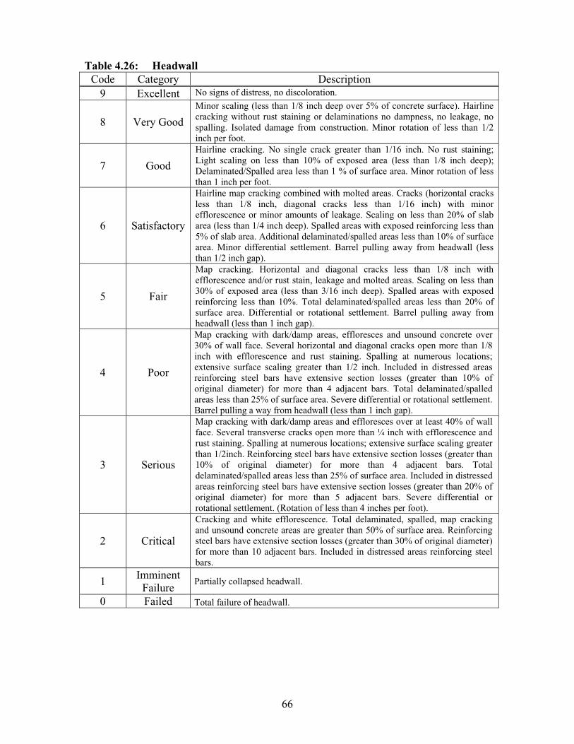
66
Table 4.26: Headwall Code Category Description
9 Excellent No signs of distress, no discoloration.
8 Very Good
Minor scaling (less than 1/8 inch deep over 5% of concrete surface). Hairline cracking without rust staining or delaminations no dampness, no leakage, no spalling. Isolated damage from construction. Minor rotation of less than 1/2 inch per foot.
7 Good
Hairline cracking. No single crack greater than 1/16 inch. No rust staining; Light scaling on less than 10% of exposed area (less than 1/8 inch deep); Delaminated/Spalled area less than 1 % of surface area. Minor rotation of less than 1 inch per foot.
6 Satisfactory
Hairline map cracking combined with molted areas. Cracks (horizontal cracks less than 1/8 inch, diagonal cracks less than 1/16 inch) with minor efflorescence or minor amounts of leakage. Scaling on less than 20% of slab area (less than 1/4 inch deep). Spalled areas with exposed reinforcing less than 5% of slab area. Additional delaminated/spalled areas less than 10% of surface area. Minor differential settlement. Barrel pulling away from headwall (less than 1/2 inch gap).
5 Fair
Map cracking. Horizontal and diagonal cracks less than 1/8 inch with efflorescence and/or rust stain, leakage and molted areas. Scaling on less than 30% of exposed area (less than 3/16 inch deep). Spalled areas with exposed reinforcing less than 10%. Total delaminated/spalled areas less than 20% of surface area. Differential or rotational settlement. Barrel pulling away from headwall (less than 1 inch gap).
4 Poor
Map cracking with dark/damp areas, effloresces and unsound concrete over 30% of wall face. Several horizontal and diagonal cracks open more than 1/8 inch with efflorescence and rust staining. Spalling at numerous locations; extensive surface scaling greater than 1/2 inch. Included in distressed areas reinforcing steel bars have extensive section losses (greater than 10% of original diameter) for more than 4 adjacent bars. Total delaminated/spalled areas less than 25% of surface area. Severe differential or rotational settlement. Barrel pulling a way from headwall (less than 1 inch gap).
3 Serious
Map cracking with dark/damp areas and effloresces over at least 40% of wall face. Several transverse cracks open more than ¼ inch with efflorescence and rust staining. Spalling at numerous locations; extensive surface scaling greater than 1/2inch. Reinforcing steel bars have extensive section losses (greater than 10% of original diameter) for more than 4 adjacent bars. Total delaminated/spalled areas less than 25% of surface area. Included in distressed areas reinforcing steel bars have extensive section losses (greater than 20% of original diameter) for more than 5 adjacent bars. Severe differential or rotational settlement. (Rotation of less than 4 inches per foot).
2 Critical
Cracking and white efflorescence. Total delaminated, spalled, map cracking and unsound concrete areas are greater than 50% of surface area. Reinforcing steel bars have extensive section losses (greater than 30% of original diameter) for more than 10 adjacent bars. Included in distressed areas reinforcing steel bars.
1Imminent
Failure Partially collapsed headwall.
0 Failed Total failure of headwall.
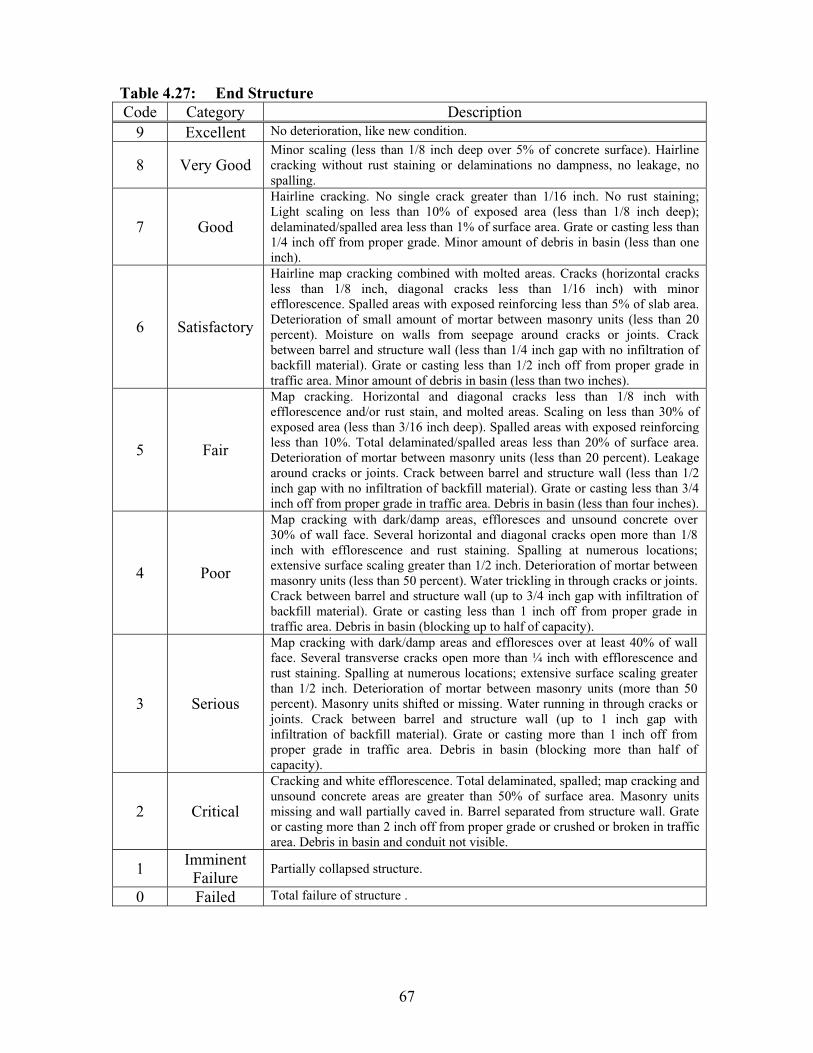
67
Table 4.27: End Structure Code Category Description
9 Excellent No deterioration, like new condition.
8 Very Good Minor scaling (less than 1/8 inch deep over 5% of concrete surface). Hairline cracking without rust staining or delaminations no dampness, no leakage, no spalling.
7 Good
Hairline cracking. No single crack greater than 1/16 inch. No rust staining; Light scaling on less than 10% of exposed area (less than 1/8 inch deep); delaminated/spalled area less than 1% of surface area. Grate or casting less than 1/4 inch off from proper grade. Minor amount of debris in basin (less than one inch).
6 Satisfactory
Hairline map cracking combined with molted areas. Cracks (horizontal cracks less than 1/8 inch, diagonal cracks less than 1/16 inch) with minor efflorescence. Spalled areas with exposed reinforcing less than 5% of slab area. Deterioration of small amount of mortar between masonry units (less than 20 percent). Moisture on walls from seepage around cracks or joints. Crack between barrel and structure wall (less than 1/4 inch gap with no infiltration of backfill material). Grate or casting less than 1/2 inch off from proper grade in traffic area. Minor amount of debris in basin (less than two inches).
5 Fair
Map cracking. Horizontal and diagonal cracks less than 1/8 inch with efflorescence and/or rust stain, and molted areas. Scaling on less than 30% of exposed area (less than 3/16 inch deep). Spalled areas with exposed reinforcing less than 10%. Total delaminated/spalled areas less than 20% of surface area. Deterioration of mortar between masonry units (less than 20 percent). Leakage around cracks or joints. Crack between barrel and structure wall (less than 1/2 inch gap with no infiltration of backfill material). Grate or casting less than 3/4 inch off from proper grade in traffic area. Debris in basin (less than four inches).
4 Poor
Map cracking with dark/damp areas, effloresces and unsound concrete over 30% of wall face. Several horizontal and diagonal cracks open more than 1/8 inch with efflorescence and rust staining. Spalling at numerous locations; extensive surface scaling greater than 1/2 inch. Deterioration of mortar between masonry units (less than 50 percent). Water trickling in through cracks or joints. Crack between barrel and structure wall (up to 3/4 inch gap with infiltration of backfill material). Grate or casting less than 1 inch off from proper grade in traffic area. Debris in basin (blocking up to half of capacity).
3 Serious
Map cracking with dark/damp areas and effloresces over at least 40% of wall face. Several transverse cracks open more than ¼ inch with efflorescence and rust staining. Spalling at numerous locations; extensive surface scaling greater than 1/2 inch. Deterioration of mortar between masonry units (more than 50 percent). Masonry units shifted or missing. Water running in through cracks or joints. Crack between barrel and structure wall (up to 1 inch gap with infiltration of backfill material). Grate or casting more than 1 inch off from proper grade in traffic area. Debris in basin (blocking more than half of capacity).
2 Critical
Cracking and white efflorescence. Total delaminated, spalled; map cracking and unsound concrete areas are greater than 50% of surface area. Masonry units missing and wall partially caved in. Barrel separated from structure wall. Grate or casting more than 2 inch off from proper grade or crushed or broken in traffic area. Debris in basin and conduit not visible.
1Imminent
Failure Partially collapsed structure.
0 Failed Total failure of structure .

68
4.6.1 Channel Alignment
The channel has to be aligned with the stream to flow through the center of the
structure. The culvert may have more than one channel flowing to the inlet such as
ditches alongside the roadway. Channel alignment rating should be governed by the
worst case. The rating should not be low if the alignment was designated to be at a severe
angle. Table 4.28 presents channel alignment rating (Item No. 9 on the CR-86 form).
Table 4.28: Channel Alignment Code Category Description
9 Excellent Channel is flowing through culvert causing no adverse conditions to channel protection or culvert.
8 Very Good Channel has straight alignment for more than 100 feet upstream. Flow hits protective materials placed to protect culvert material.
7 Good Silt and gravel buildup restricts half of the channel; Tree or bush growing in the channel.
6 Satisfactory
Flows through lout of 2 pipes; Flows along one abut. Doesn't flow under center of the culvert; minor curve (20o-40o angle); Deposits causing channel to split into 2 or more small channels. Minor streambed movement evident.
5 Fair
Flow hits outside headwall into unprotected embankment. Stream has meandered or has deposited sediment diverting flow causing erosion to embankment (Flow angle between 40°-50°) Trees and brushes restrict the channel.
4 Poor
Flows into or along wall to expose footing. Stream has meandered or has deposited sediment diverting flow causing erosion to embankment(Flow angle between 50°-70°) Flow enters pipe by other means than designed opening.
3 Serious
80° -90° turns at the bridge causing erosion behind wingwall. Loss of embankment material. Erosion to embankment encroaching on roadway. Lateral movement has changed the waterway to now threaten the culvert and /or approach roadway.
2 Critical Flow is piping around culvert. Erosion to embankment impacting roadway surface. The water way has changed to the extent the bridge is near a state of collapse.
1Imminent
Failure No flow enters culvert. All of the flow pipes around culvert barrel. Bridge closed because of channel failure.
0 Failed Total failure of pipe.

69
4.6.2 Channel Protection
This item represents the method used to protect the bridge and channel banks
from scouring and other degradation caused by stream actions. Table 4.29 presents
channel protection rating (Item No. 10 on the CR-86 form).
Table 4.29: Channel Protection Code Category Description
9 Excellent Embankment protection are not required or are in a stable condition.
8 Very Good No noteworthy deficiencies, which affect the condition of the channel protection 100 feet upstream. Banks are protected or well vegetated.
7 Good Channel bank(s) is beginning to slump. Embankment protection has minor damage. Bank protection is in need of minor repairs.
6 Satisfactory Riprap starting to washed away. Minor erosion. Cracked concrete channel protection at inlet of a culvert.
5 Fair Broken up concrete channel protection at inlet of a culvert. Bank protection is being eroded.
4 Poor Channel protection is severely undermined; Stone is completely washed away; Major erosion; Failed concrete channel protection at inlet of a culvert. Bank or embankment protection is severely undermined.
3 Serious Channel protection has failed; channel has moved to where the bridge and approach roadway are threatened.
2 Critical Channel protection has failed; channel flow is causing scour effects.
1 Imminent Failure Culvert closed because of channel failure.
0 Failed Total failure of pipe.
4.6.3 Culvert Waterway Blockage
Waterway blockage involves checking for indications of an inadequate opening.
Contraction scour and stream bed degradation can be increased due to inadequate
waterway areas in the culvert barrel. Geometry of barrel, amount of debris, and the
adequacy of freeboard should be considered in determining waterway adequacy. In rating
waterway blockage, the inspector should check for scour of the stream bed, banks,
formation of sandbars, or debris, which could change flow direction. Table 4.30 presents
culvert waterway blockage rating (Item No. 11 on the CR-86 form).
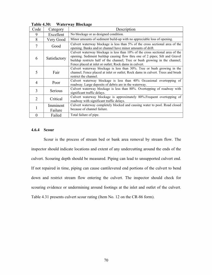
70
Table 4.30: Waterway Blockage Code Category Description
9 Excellent No blockage or as designed condition.
8 Very Good Minor amounts of sediment build-up with no appreciable loss of opening.
7 Good Culvert waterway blockage is less than 5% of the cross sectional area of the opening. Banks and/or channel have minor amounts of drift.
6 Satisfactory
Culvert waterway blockage is less than 10% of the cross sectional area of the opening. Sediment buildup causing flow thru one of 2 pipes; Silt and Gravel buildup restricts half of the channel; Tree or bush growing in the channel; Fence placed at inlet or outlet; Rock dams in culvert.
5 Fair Culvert waterway blockage is less than 30%. Tree or bush growing in the channel; Fence placed at inlet or outlet; Rock dams in culvert. Trees and brush restrict the channel.
4 Poor Culvert waterway blockage is less than 40% Occasional overtopping of roadway. Large deposits of debris are in the waterway.
3 Serious Culvert waterway blockage is less than 80%. Overtopping of roadway with significant traffic delays.
2 Critical Culvert waterway blockage is approximately 80%.Frequent overtopping of roadway with significant traffic delays.
1Imminent
Failure Culvert waterway completely blocked and causing water to pool. Road closed because of channel failure.
0 Failed Total failure of pipe.
4.6.4 Scour
Scour is the process of stream bed or bank area removal by stream flow. The
inspector should indicate locations and extent of any undercutting around the ends of the
culvert. Scouring depth should be measured. Piping can lead to unsupported culvert end.
If not repaired in time, piping can cause cantilevered end portions of the culvert to bend
down and restrict stream flow entering the culvert. The inspector should check for
scouring evidence or undermining around footings at the inlet and outlet of the culvert.
Table 4.31 presents culvert scour rating (Item No. 12 on the CR-86 form).
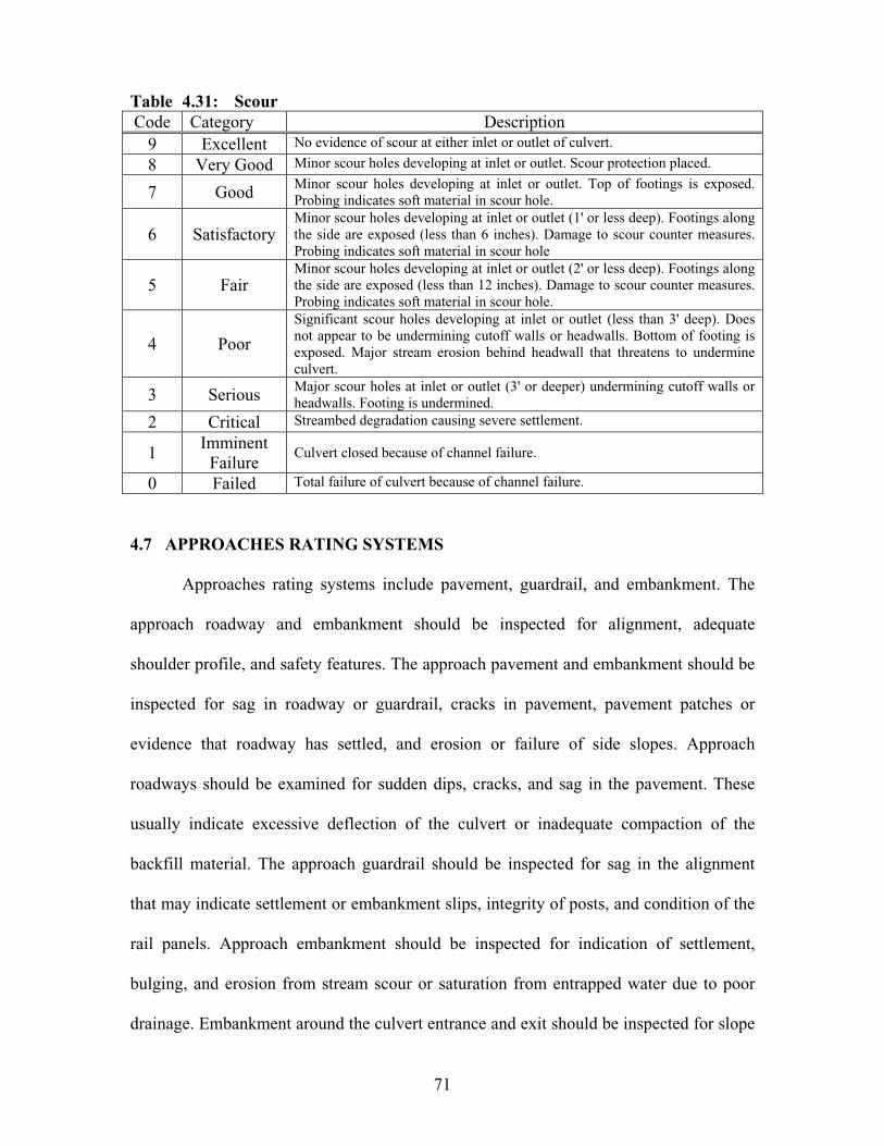
71
Table 4.31: Scour Code Category Description
9 Excellent No evidence of scour at either inlet or outlet of culvert.
8 Very Good Minor scour holes developing at inlet or outlet. Scour protection placed.
7 Good Minor scour holes developing at inlet or outlet. Top of footings is exposed. Probing indicates soft material in scour hole.
6 Satisfactory Minor scour holes developing at inlet or outlet (1' or less deep). Footings along the side are exposed (less than 6 inches). Damage to scour counter measures. Probing indicates soft material in scour hole
5 Fair Minor scour holes developing at inlet or outlet (2' or less deep). Footings along the side are exposed (less than 12 inches). Damage to scour counter measures. Probing indicates soft material in scour hole.
4 Poor
Significant scour holes developing at inlet or outlet (less than 3' deep). Does not appear to be undermining cutoff walls or headwalls. Bottom of footing is exposed. Major stream erosion behind headwall that threatens to undermine culvert.
3 Serious Major scour holes at inlet or outlet (3' or deeper) undermining cutoff walls or headwalls. Footing is undermined.
2 Critical Streambed degradation causing severe settlement.
1Imminent
Failure Culvert closed because of channel failure.
0 Failed Total failure of culvert because of channel failure.
4.7 APPROACHES RATING SYSTEMS
Approaches rating systems include pavement, guardrail, and embankment. The
approach roadway and embankment should be inspected for alignment, adequate
shoulder profile, and safety features. The approach pavement and embankment should be
inspected for sag in roadway or guardrail, cracks in pavement, pavement patches or
evidence that roadway has settled, and erosion or failure of side slopes. Approach
roadways should be examined for sudden dips, cracks, and sag in the pavement. These
usually indicate excessive deflection of the culvert or inadequate compaction of the
backfill material. The approach guardrail should be inspected for sag in the alignment
that may indicate settlement or embankment slips, integrity of posts, and condition of the
rail panels. Approach embankment should be inspected for indication of settlement,
bulging, and erosion from stream scour or saturation from entrapped water due to poor
drainage. Embankment around the culvert entrance and exit should be inspected for slope
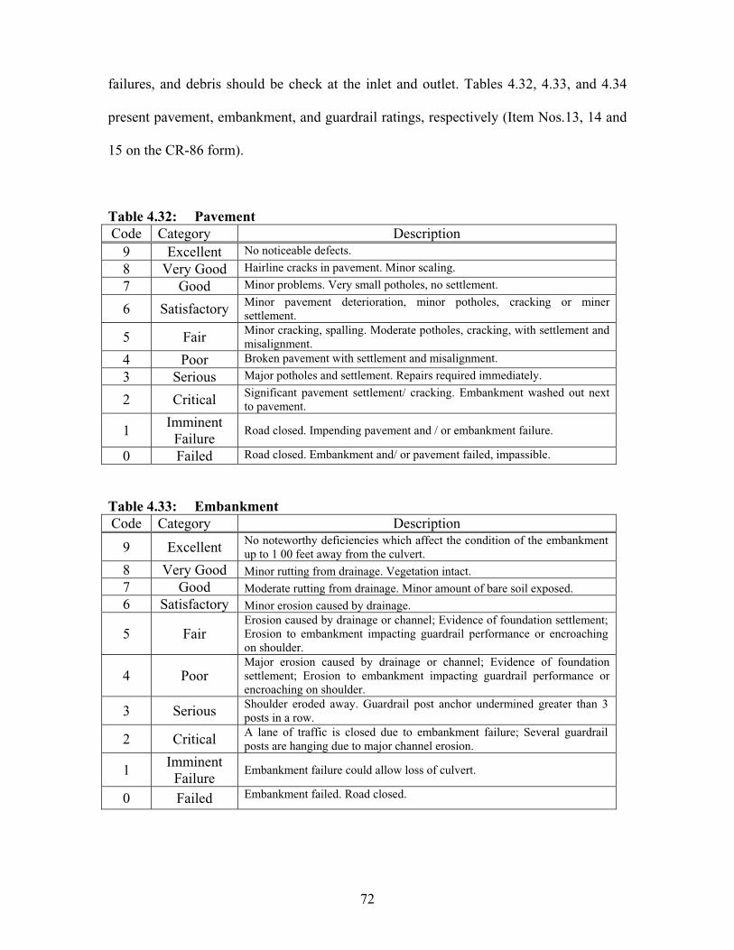
72
failures, and debris should be check at the inlet and outlet. Tables 4.32, 4.33, and 4.34
present pavement, embankment, and guardrail ratings, respectively (Item Nos.13, 14 and
15 on the CR-86 form).
Table 4.32: Pavement Code Category Description
9 Excellent No noticeable defects.
8 Very Good Hairline cracks in pavement. Minor scaling.
7 Good Minor problems. Very small potholes, no settlement.
6 Satisfactory Minor pavement deterioration, minor potholes, cracking or miner settlement.
5 Fair Minor cracking, spalling. Moderate potholes, cracking, with settlement and misalignment.
4 Poor Broken pavement with settlement and misalignment.
3 Serious Major potholes and settlement. Repairs required immediately.
2 Critical Significant pavement settlement/ cracking. Embankment washed out next to pavement.
1Imminent
Failure Road closed. Impending pavement and / or embankment failure.
0 Failed Road closed. Embankment and/ or pavement failed, impassible.
Table 4.33: Embankment Code Category Description
9 Excellent No noteworthy deficiencies which affect the condition of the embankment up to 1 00 feet away from the culvert.
8 Very Good Minor rutting from drainage. Vegetation intact. 7 Good Moderate rutting from drainage. Minor amount of bare soil exposed. 6 Satisfactory Minor erosion caused by drainage.
5 Fair Erosion caused by drainage or channel; Evidence of foundation settlement; Erosion to embankment impacting guardrail performance or encroaching on shoulder.
4 Poor Major erosion caused by drainage or channel; Evidence of foundation settlement; Erosion to embankment impacting guardrail performance or encroaching on shoulder.
3 Serious Shoulder eroded away. Guardrail post anchor undermined greater than 3 posts in a row.
2 Critical A lane of traffic is closed due to embankment failure; Several guardrail posts are hanging due to major channel erosion.
1Imminent
Failure Embankment failure could allow loss of culvert.
0 Failed Embankment failed. Road closed.
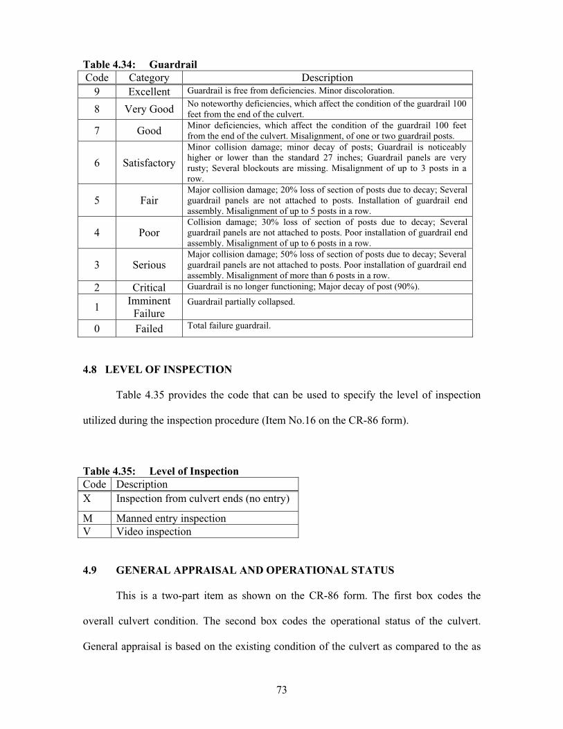
73
Table 4.34: Guardrail Code Category Description
9 Excellent Guardrail is free from deficiencies. Minor discoloration.
8 Very Good No noteworthy deficiencies, which affect the condition of the guardrail 100 feet from the end of the culvert.
7 Good Minor deficiencies, which affect the condition of the guardrail 100 feet from the end of the culvert. Misalignment, of one or two guardrail posts.
6 Satisfactory
Minor collision damage; minor decay of posts; Guardrail is noticeably higher or lower than the standard 27 inches; Guardrail panels are very rusty; Several blockouts are missing. Misalignment of up to 3 posts in a row.
5 Fair Major collision damage; 20% loss of section of posts due to decay; Several guardrail panels are not attached to posts. Installation of guardrail end assembly. Misalignment of up to 5 posts in a row.
4 Poor Collision damage; 30% loss of section of posts due to decay; Several guardrail panels are not attached to posts. Poor installation of guardrail end assembly. Misalignment of up to 6 posts in a row.
3 Serious Major collision damage; 50% loss of section of posts due to decay; Several guardrail panels are not attached to posts. Poor installation of guardrail end assembly. Misalignment of more than 6 posts in a row.
2 Critical Guardrail is no longer functioning; Major decay of post (90%).
1Imminent
Failure Guardrail partially collapsed.
0 Failed Total failure guardrail.
4.8 LEVEL OF INSPECTION
Table 4.35 provides the code that can be used to specify the level of inspection
utilized during the inspection procedure (Item No.16 on the CR-86 form).
Table 4.35: Level of Inspection Code Description X Inspection from culvert ends (no entry)
M Manned entry inspection V Video inspection
4.9 GENERAL APPRAISAL AND OPERATIONAL STATUS
This is a two-part item as shown on the CR-86 form. The first box codes the
overall culvert condition. The second box codes the operational status of the culvert.
General appraisal is based on the existing condition of the culvert as compared to the as
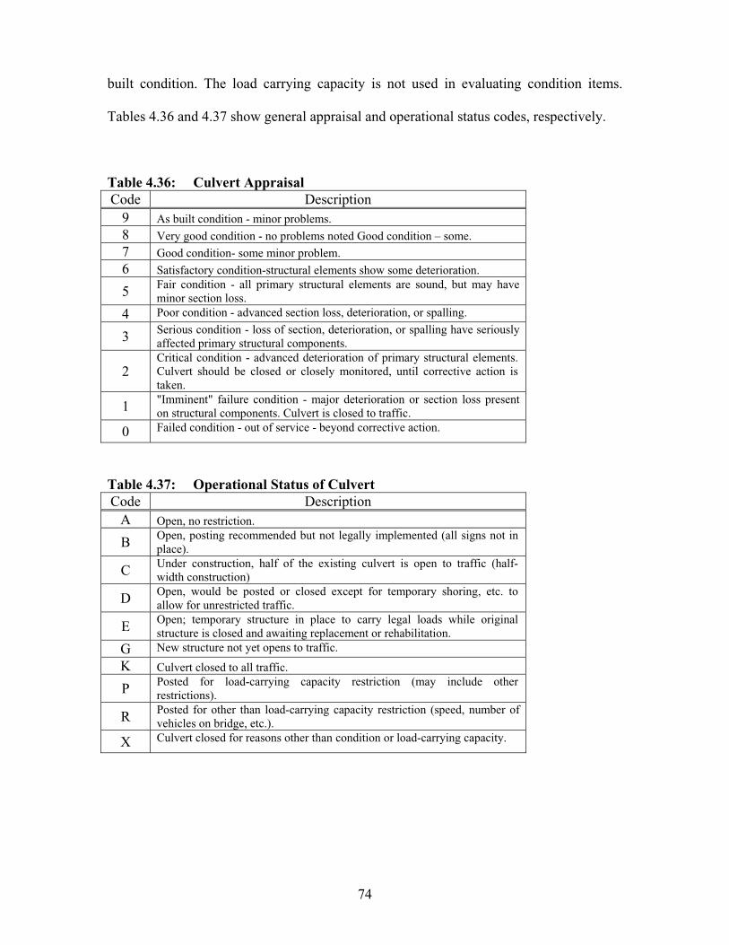
74
built condition. The load carrying capacity is not used in evaluating condition items.
Tables 4.36 and 4.37 show general appraisal and operational status codes, respectively.
Table 4.36: Culvert Appraisal Code Description
9 As built condition - minor problems. 8 Very good condition - no problems noted Good condition – some. 7 Good condition- some minor problem. 6 Satisfactory condition-structural elements show some deterioration.
5 Fair condition - all primary structural elements are sound, but may have minor section loss.
4 Poor condition - advanced section loss, deterioration, or spalling.
3 Serious condition - loss of section, deterioration, or spalling have seriously affected primary structural components.
2Critical condition - advanced deterioration of primary structural elements. Culvert should be closed or closely monitored, until corrective action is taken.
1 "Imminent" failure condition - major deterioration or section loss present on structural components. Culvert is closed to traffic.
0 Failed condition - out of service - beyond corrective action.
Table 4.37: Operational Status of Culvert Code Description
A Open, no restriction.
B Open, posting recommended but not legally implemented (all signs not in place).
C Under construction, half of the existing culvert is open to traffic (half-width construction)
D Open, would be posted or closed except for temporary shoring, etc. to allow for unrestricted traffic.
E Open; temporary structure in place to carry legal loads while original structure is closed and awaiting replacement or rehabilitation.
G New structure not yet opens to traffic.
K Culvert closed to all traffic.
P Posted for load-carrying capacity restriction (may include other restrictions).
R Posted for other than load-carrying capacity restriction (speed, number of vehicles on bridge, etc.).
X Culvert closed for reasons other than condition or load-carrying capacity.
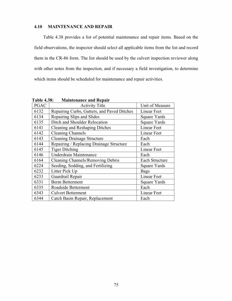
75
4.10 MAINTENANCE AND REPAIR
Table 4.38 provides a list of potential maintenance and repair items. Based on the
field observations, the inspector should select all applicable items from the list and record
them in the CR-86 form. The list should be used by the culvert inspection reviewer along
with other notes from the inspection, and if necessary a field investigation, to determine
which items should be scheduled for maintenance and repair activities.
Table 4.38: Maintenance and Repair PGAC Activity Title Unit of Measure 6132 Repairing Curbs, Gutters, and Paved Ditches Linear Feet 6134 Repairing Slips and Slides Square Yards 6135 Ditch and Shoulder Relocation Square Yards 6141 Cleaning and Reshaping Ditches Linear Feet 6142 Cleaning Channels Linear Feet 6143 Cleaning Drainage Structure Each 6144 Repairing / Replacing Drainage Structure Each 6145 Tiger Ditching Linear Feet 6146 Underdrain Maintenance Each 6164 Cleaning Channels/Removing Debris Each Structure 6224 Seeding, Sodding, and Fertilizing Square Yards 6232 Litter Pick Up Bags 6233 Guardrail Repair Linear Feet 6331 Berm Betterment Square Yards 6335 Roadside Betterment Each 6343 Culvert Betterment Linear Feet 6344 Catch Basin Repair, Replacement Each

76

77
CHAPTER 5: FIELD INSPECTION OF HIGHWAY CULVERTS
5.1 INTRODUCTION
Under Task 3 of the project, a total of sixty (60) highway culverts in Ohio were to
be inspected according to the methodology presented in the ODOT Culvert Management
Manual (2003), described in detail previously in Chapter 4, as well as a more
comprehensive methodology to be developed by ORITE. The goals of the state-wide
culvert inspection program were to:
Identify common distresses for each major type of highway culverts in Ohio.
Identify trends among the field data collected.
Evaluate the overall effectiveness of the methodology presented in the ODOT
Culvert Management Manual (2003).
Identify areas in which the new ODOT methodology can be further improved.
Formulate a comprehensive culvert risk assessment method based on the data
gathered during the field inspection program and results of statistical analysis.
Compile a library of high-resolution photographs for ODOT which can be
used in culvert inspection training programs.
5.2 CULVERT SELECTION METHODOLOGY
A formal request was issued from the ODOT central office to each ODOT district
office to supply an inventory list of highway culvert structures recommended for the field
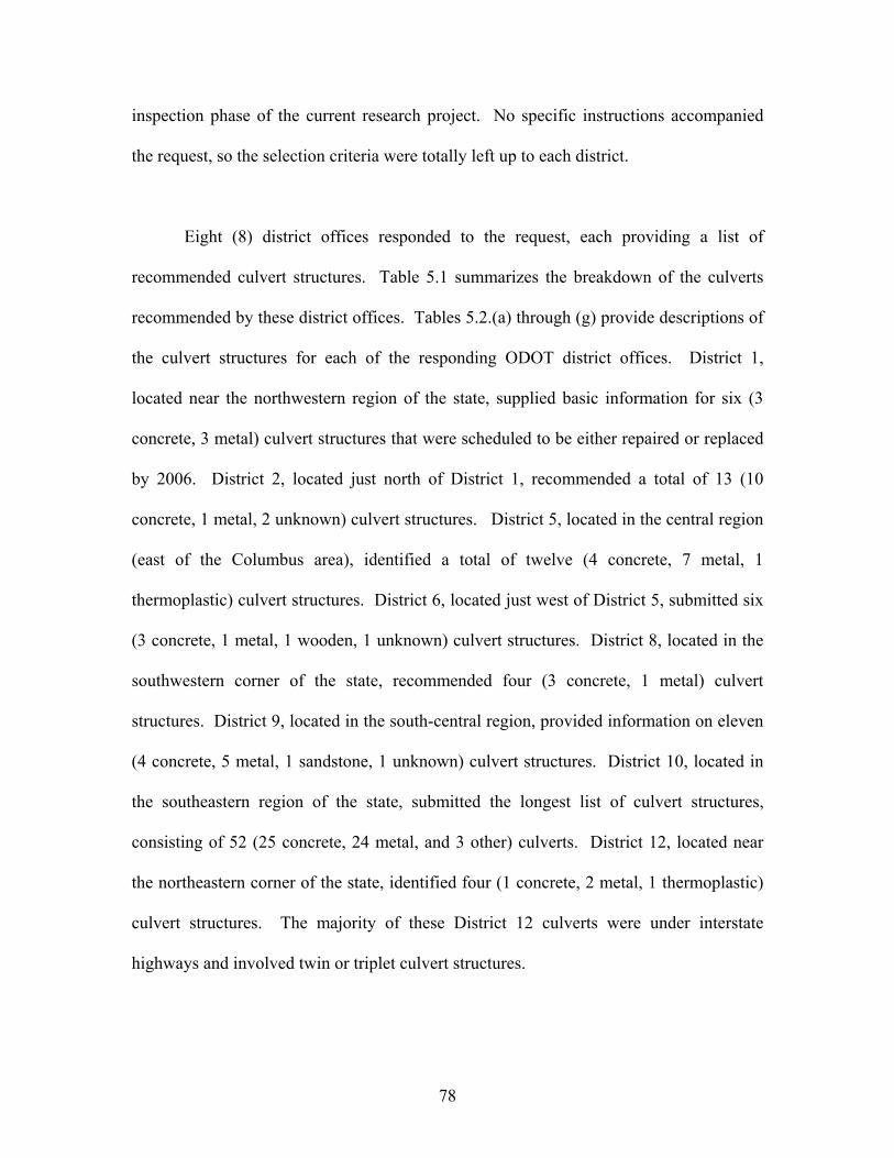
78
inspection phase of the current research project. No specific instructions accompanied
the request, so the selection criteria were totally left up to each district.
Eight (8) district offices responded to the request, each providing a list of
recommended culvert structures. Table 5.1 summarizes the breakdown of the culverts
recommended by these district offices. Tables 5.2.(a) through (g) provide descriptions of
the culvert structures for each of the responding ODOT district offices. District 1,
located near the northwestern region of the state, supplied basic information for six (3
concrete, 3 metal) culvert structures that were scheduled to be either repaired or replaced
by 2006. District 2, located just north of District 1, recommended a total of 13 (10
concrete, 1 metal, 2 unknown) culvert structures. District 5, located in the central region
(east of the Columbus area), identified a total of twelve (4 concrete, 7 metal, 1
thermoplastic) culvert structures. District 6, located just west of District 5, submitted six
(3 concrete, 1 metal, 1 wooden, 1 unknown) culvert structures. District 8, located in the
southwestern corner of the state, recommended four (3 concrete, 1 metal) culvert
structures. District 9, located in the south-central region, provided information on eleven
(4 concrete, 5 metal, 1 sandstone, 1 unknown) culvert structures. District 10, located in
the southeastern region of the state, submitted the longest list of culvert structures,
consisting of 52 (25 concrete, 24 metal, and 3 other) culverts. District 12, located near
the northeastern corner of the state, identified four (1 concrete, 2 metal, 1 thermoplastic)
culvert structures. The majority of these District 12 culverts were under interstate
highways and involved twin or triplet culvert structures.

79
Table 5.1: Type and Number of Highway Culverts Recommended by Districts No. of Culverts by Type:
Concrete: CMP Plastic Dist.No.
Office Location
Box Pipe Arch Slab Pipe Arch H P Other & Unknown
1 Lima 0 1 0 2 2 1 0 0 0 2 Bowling Green 6 1 0 3 0 1 0 0 2 5 Jacksontown 2 2 0 0 7 0 1 0 0 6 Delaware 3 0 0 0 1 0 0 0 2 8 Lebanon 0 1 0 2 0 1 0 0 0 9 Chillicothe 1 0 2 1 3 2 0 0 2 10 Marietta 21 4 0 0 12 12 0 0 3 12 Garfield Heights 0 3 0 0 3 0 3 0 0 TOTAL = 113 33 12 2 8 28 17 4 0 9 [Notes] - Other types included culverts made of brick, timber, sandstone, and clay.
- Under Plastic, H = HDPE & P = PVC.
Table 5.2.(a): Culvert Structures Recommended by ODOT District 1 Culvert I.D. Type Size Year Length (ft.) Cover (ft.) WYA-103-1.06 Concrete, Slab 5’-0” Span 1955 NA NA PUT-189-10.5 Concrete, Slab 9’-0” Span 1956 NA NA PUT-15-14.78 CMP 8’-0” Dia. 1959 NA NA PAU-66-2.44 CMP, Twins 4’-6” & 4’-6” Dia. 1955 NA NA HAN-224-6.84 Concrete, Pipe 6’-0” Dia. 1956 NA NA DEF-18-20.6 Metal, Pipe-Arch 3’-8” Span x 6’-0” Rise 1941 NA NA [Note] “NA” = Not Available; 1’ = 0.31 m; 1” = 25 mm.
Table 5.2.(b): Culvert Structures Recommended by ODOT District 2 Culvert I.D. Type Size Year Length (ft.) Cover (ft.) FUL-20-2.14 Concrete, Ellipse 4’-2” Span NA 70 NA FUL-20-0.56 Unknown 2’-0” Dia. NA 45 NA FUL-30-1.59 Concrete, Box 5’-0” Span x 3’-4” Rise NA 32 NA FUL-20A-9.70 Metal, Pipe-Arch 10’-0” Span x 6’-0” Rise NA 80 NA HEN-65-6.51 Concrete, Box 8’-0” Span x 5’-0” Rise NA NA NA HEN-65-8.86 Concrete, Box 6’-0” Span x 5’-0” Rise NA NA NA SAN-635-1.40 Concrete, Box 8’-0” Span x 8’-0” Rise NA NA NA SAN-6-20.91 Concrete, Box 8’-0” Span x 8’-0” Rise NA NA NA SEN-635-1.40 Unknown 6’-0” NA 50 NA WOO-199-22.2 Concrete, Slab 8’-0” Span NA NA NA WOO-199-25.1 Concrete, Box 5’-0” Span NA NA NA WOO-65-0.69 Concrete, Slab 8’-0” Span NA NA NA WOO-65-13.43 Concrete, Slab 4’-0” Span NA NA NA [Note] “NA” = Not Available; 1’ = 0.31 m; 1” = 25 mm.

80
Table 5.2.(c): Culvert Structures Recommended by ODOT District 5 Culvert I.D. Type Size Year Length (ft.) Cover (ft.) MUS-93-1.76 CMP 8’-0” Dia. NA 360 NA LIC-70-13.52 Concrete, Pipe 6’-0” Dia. NA 285 15 GUE-70-6.59 CMP 3’-6” Dia. NA 568 40 GUE-70-8.94 CMP 5’-0” Dia. NA 366 25 GUE-77-7.85R CMP 6’-0” Dia. NA 360 40 GUE-77-14.72 CMP 8’-0” Dia. NA 342 40 LIC-16-13.66 CMP 6’-4” Dia. NA 164 NA KNO-95-0.08 CMP 4’-0” Dia. NA 60 5 GUE-821-3.03 Concrete, Box 5’-0” Span x 4’-0” Rise NA 34 5 COS-93-11.54 Concrete, Box 7’-0” Span x 5’-0” Rise NA 50 NA LIC-70-13.52 Concrete, Pipe 6’-0” Dia. NA 285 15 PER-13-11.14 Plastic (HDPE) 3’-6” Dia. NA 60 3 [Note] “NA” = Not Available; 1’ = 0.31 m; 1” = 25 mm.
Table 5.2.(d): Culvert Structures Recommended by ODOT District 6 Culvert I.D. Type Size Year Length (ft.) Cover (ft.) MAD-29-8.80 CMP 7’-0” Dia. NA NA NA MAD-29-11.37 Concrete, Box 4’-0” Span NA NA NA MAD-142-4.30 Concrete, Box 4’-0” Span x 6’-0” Rise NA NA NA UNI-4-25.04 Wood, Deck 6’-0” Span NA NA NA FAY-753-2.09 Concrete, Box NA NA NA NA PIC-22-? Unknown NA NA NA NA [Note] “NA” = Not Available; 1’ = 0.31 m; 1” = 25 mm.
Table 5.2.(e): Culvert Structures Recommended by ODOT District 8 Culvert I.D. Type Size Year Length (ft.) Cover (ft.) BUT-126-2.58 Concrete, Slab 8’-6” Span NA 52.5 1.5 CLI-28-7.84 Concrete, Slab 8’-0” Span 1932 34 1.5 CLI-124-0.03 Metal, Pipe-Arch 9’-6” Span x 6’-5” Rise 1956 106 1.75 GRE-380-5.03 Concrete, Pipe 2’-6” Dia. 1941 45 2.1 [Note] “NA” = Not Available; 1’ = 0.31 m; 1” = 25 mm.
Table 5.2.(f): Culvert Structures Recommended by ODOT District 9 Culvert I.D. Type Size Year Length (ft.) Cover (ft.) HIG-50-23.93 Concrete, Arch 6’-8” Span x 3’-0” Rise NA NA NA HIG-134-16.34 Sandstone, Arch NA NA NA NA HIG-50-19.82 CMP 6’-0” Dia. NA NA NA ADA-348-10.22 Unknown 3’-6” Dia. ; Twins NA NA NA ADA-125-19.02 Concrete, Arch NA NA NA NA ADA-247-11.87 Metal, Pipe-Arch 5’-4” Span x 3’-6” Rise NA NA NA BRO-52-16.16 Concrete, Box NA NA NA NA PIK-32-15.96 CMP 7’-0” Dia. NA NA NA PIK-772-0.98 CMP 3’-0” Dia. NA NA NA JAC-93-21.04 Concrete, Slab 8’-0” Span NA NA NA JAC-124-17.12 Metal, Pipe-Arch 7’-3” Span x 5’-3” Rise NA NA NA [Note] “NA” = Not Available; 1’ = 0.31 m; 1” = 25 mm.

81
Table 5.2.(g): Culvert Structures Recommended by ODOT District 10 Culvert I.D. Type Size Year Length (ft.) Cover (ft.) GAL-7-12.54 CMP 3’-0” Dia. 1930 84 9 GAL-141-21.55 Concrete, Pipe NA NA 1150 3 HOC-328-4.93 Clay, Pipe 3’-0” Dia. 1966 44 3 WAS-60-4.84 CMP 8’-0” Dia. 1961 150 21 GAL-7-0.22 CMP 2’-6” Dia. 1939 104 14 HOC-93-1.1 Concrete, Box 6’-0” Span x 4’-0” Rise 1968 81 2 ATH-78-4.08 CMP 1-3” Dia. 1938 202 28 ATH-78-4.17 CMP 1’-6” Dia. 1938 108 17 VIN-93-11.17 CMP 1-3” Dia. 1958 122 11 HOC-78-1.05 Concrete, Box 6’-0” Span x 4’-0” Rise 1924 39 1 GAL-7-21.3 CMP 2’-6” Dia. 1940 108 11 ATH-278-0.25 Metal, Pipe-Arch 6’-11” Span x 4’-0” Rise NA 40 NA ATH-690-0.68 Concrete, Pipe 1’-6” Dia. 1939 70 16 GAL-7-29.86 Concrete, Pipe 3’-0” Dia. 1936 139 15 HOC-56-2.83 CMP 3’-0” Dia.; Twin NA 90 NA HOC-56-15.26 Metal, Pipe-Arch 8’-2” Span x 6’-9” Rise 1948 32 2 HOC-56-17.57 Metal, Pipe-Arch 6’-4” Span x 4’-9” Rise 1951 56 1 HOC-78-0.72 Concrete, Box 6’-0” Span x 3’-0” Rise 1924 30 1 HOC-216-2.77 Concrete, Box 9’-0” Span x 7’-0” Rise 1961 32 NA HOC-216-3.25 Concrete, Box 4’-0” Span x 3’-0” Rise NA 43 2 HOC-216-3.43 Concrete, Box 5’-0” Span x 3’-0” Rise 1932 56 2 HOC-595-1.35 Metal, Pipe-Arch 3’-6” Span x 2-3” Rise ;
Twin1961 40 2
HOC-595-2.85 Metal, Pipe-Arch 7’-8” Span x 5’-5” Rise 1951 52 1 HOC-595-4.57 Metal, Pipe-Arch 7’-3” Span x 5’-3” Rise 1961 60 2 HOC-664-6.88 Metal, Pipe-Arch 6’-1” Span x 4’-7” Rise NA 104 3 HOC-664-11.87 Metal, Pipe-Arch 9’-6” Span x 6’-5” Rise 1959 70 4 HOC-664-17.16 Metal, Pipe-Arch 8’-7” Span x 5’-11” Rise 1959 66 1 HOC-664-22.4 CMP 7’-0” Dia. 1956 100 12 MEG-124-24.65 Sandstone, Arch 8’-0” Span x 8’-6” Rise 1900 73 16 MEG-124-30.17 Concrete, Box 3’-0” Span x 4’-0” Rise NA 50 3 MEG-338-16.42 Concrete, Box 4’-0” Span x 4’-0” Rise NA 74 8 MEG-681-7.94 CMP 6’-0” Dia. 1962 74 6 MEG-681-13.96 Metal, Pipe-Arch 7’-3” Span x 5’-3” Rise 1960 72 4 MEG-681-18.86 Metal, Pipe-Arch 6’-1” Span x 4’-7” Rise 1953 40 2 MRG-37-1.57 Concrete, Box 2’-6” Span x 2’-6” Rise 1923 31 2 MRG-37-2.66 Concrete, Box 2’-6” Span x 2’-6” Rise 1922 31 2 MRG-37-7.43 Concrete, Box 3’-0” Span x 2’-6” Rise 1930 29 4 MRG-37-7.56 Concrete, Box 4’-0” Span x 3’-0” Rise 1930 54 4 MRG-37-7.68 Concrete, Box 2’-0” Span x 2’-0” Rise 1930 44 6 MRG-60-19.95 Concrete, Box 4’-0” Span x 6’-0” Rise 1930 50 3 MRG-78-8.56 Concrete, Box 6’-0” Span x 4’-0” Rise 1928 68 5 MRG-78-11.34 Concrete, Box 8’-0” Span x 6’-0” Rise 1928 44 3 MRG-78-15.96 Concrete, Box 5’-0” Span x 3’-0” Rise NA 52 5 MRG-78-24.40 Concrete, Box 4’-0” Span x 3’-0” Rise 1968 30 1 MRG-78-24.97 Concrete, Box 2’-6” Span x 2’-6” Rise 1968 42 4 MRG-377-5.06 Concrete, Box 5’-0” Span x 4’-0” Rise 1926 32 1 NOB-146-13.75 CMP 3’-0” Dia. 1955 40.5 1 VIN-50-15.41 Brick, Box 4’-0” Span x 4’-0” Rise 1920 22 2 [Note] “NA” = Not Available; 1’ = 0.31 m; 1” = 25 mm.
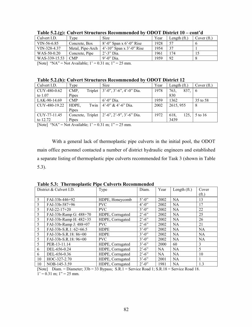
82
Table 5.2.(g): Culvert Structures Recommended by ODOT District 10 – cont’d Culvert I.D. Type Size Year Length (ft.) Cover (ft.) VIN-56-6.85 Concrete, Box 8’-0” Span x 6’-0” Rise 1928 57 6 VIN-328-4.37 Metal, Pipe-Arch 4’-10” Span x 3’-0” Rise 1954 37 1 WAS-50-0.20 Concrete, Pipe 2’-3” Dia. 1961 174 15 WAS-339-15.53 CMP 9’-0” Dia. 1959 92 8 [Note] “NA” = Not Available; 1’ = 0.31 m; 1” = 25 mm.
Table 5.2.(h): Culvert Structures Recommended by ODOT District 12 Culvert I.D. Type Size Year Length (ft.) Cover (ft.) CUY-480-0.62 to 1.07
CMP, Triplet Pipes
3’-0”, 3’-6”, 4’-0” Dia. 1978 763, 837, 830
6
LAK-90-14.69 CMP 6’-0” Dia. 1959 1362 35 to 58 CUY-480-19.22 HDPE, Twin
Pipes4’-0” & 4’-6” Dia. 2002 2615, 955 8
CUY-77-11.45 to 12.72
Concrete, Triplet Pipes
2’-6”, 2’-9”, 3’-6” Dia. 1972 618, 125, 3439
5 to 16
[Note] “NA” = Not Available; 1’ = 0.31 m; 1” = 25 mm.
With a general lack of thermoplastic pipe culverts in the initial pool, the ODOT
main office personnel contacted a number of district hydraulic engineers and established
a separate listing of thermoplastic pipe culverts recommended for Task 3 (shown in Table
5.3).
Table 5.3: Thermoplastic Pipe Culverts Recommended District & Culvert I.D. Type Diam. Year Length (ft.) Cover
(ft.) 5 FAI-33b-446+92 HDPE, Honeycomb 5’-0” 2002 NA 13 5 FAI-33b-587+96 PVC 4’-0” 2002 NA 17 5 FAI-22-17+20 PVC 3’-0” 2002 NA 22 5 FAI-33b-Ramp G: 488+70 HDPE, Corrugated 2’-6” 2002 NA 25 5 FAI-33b-Ramp H: 482+35 HDPE, Corrugated 2’-6” 2002 NA 26 5 FAI-33b-Ramp J: 488+07 PVC 2’-6” 2002 NA 21 5 FAI-33b-S.R.1: 62+66.5 HDPE 3’-0” 2002 NA NA 5 FAI-33b-S.R.18: 86+00 HDPE 3’-0” 2002 NA NA 5 FAI-33b-S.R.18: 96+00 PVC 3’-0” 2002 NA NA 5 PER-13-11.14 HDPE, Corrugated 3’-6” 2000 60 3 6 DEL-656-0.24 HDPE, Corrugated 2’-6” NA NA 5 6 DEL-656-0.36 HDPE, Corrugated 2’-6” NA NA 10 10 HOC-327-2.70 HDPE, Corrugated 3’-6” 2001 NA 1 10 NOB-145-3.59 HDPE, Corrugated 2’-0” 1981 NA 1.3 [Note] Diam. = Diameter; 33b = 33 Bypass; S.R.1 = Service Road 1; S.R.18 = Service Road 18. 1’ = 0.31 m; 1” = 25 mm.

83
Once the lists of recommended culvert structures were received from the district
offices, sixty structures were to be selected by the ORITE personnel in consultation with
the ODOT for the field inspection phase. With the total number specified to be 60, the
target number for each culvert material type was initially set at -- concrete culverts (25
structures), metal culverts (25 structures), and thermoplastic pipe culverts (10 structures).
While selecting the culvert structures from the district composite lists, culverts
under interstate highways received priority. A decision was made not to inspect culverts
that are less than 24 inches (0.61 m) in span, due to general difficulty in inspecting these
small size culverts. Also, it was decided to exclude any culverts that are constructed
from materials other than concrete, corrugated metal, or thermoplastics (ex. sandstone,
timber, brick, …). This was because the majority of highway culverts in Ohio are made
from concrete, corrugated metal, and thermoplastics. An effort was made in selecting the
sixty culverts to reflect a variety of conditions for the following key characteristic
parameters to produce relatively unbiased sample populations for the subsequent
statistical analysis.
Material type (concrete; metal; thermoplastic).
Shape type (circular pipe; pipe-arch; box; ellipse; slab-on-top).
Age (less than 30 years; 30 to 60 years; more than 60 years).
Size classification – Diameter or Rise in (2’ to 4’), (4’ to 6’), and (> 6’); or
Diameter or Rise in (0.61 to 1.22 m), (1.22 to 1.83 m), and (> 1.83 m).
Ratio of (Soil Cover Height) divided by (Culvert Diameter or Rise).
Classification of roadway (interstate; U.S. route; state route; …).

84
Environmental conditions (abrasive & nonabrasive drainage flow; low-pH drainage flow).
Types of Problem:
Metal (deflections; corrosion; stress cracks; alignment; settlement; seam problem; scouring).
Concrete (cracking; spalling; alignment; settlement; joint opening; scouring).
Plastic (excessive deflections; wall buckling; cracking; alignment; settlement; joint opening).
5.3 CHARACTERISTICS OF SELECTED CULVERTS
5.3.1 List of Culverts Selected and Inspected
The culvert structures selected for inspection are listed in Table 5.4. In most
cases, the research team was able to locate the selected culvert and inspect it in detail in
the field. In a few isolated instances in District 12, the team could not locate the selected
culvert structure and had to find a comparable alternate structure in the same
geographical area. The final list included six (3 concrete, 3 metal) from District 1,
fourteen (2 concrete, 5 metal, 7 thermoplastic) from District 5, five (4 concrete, 1 metal)
from District 6, four (3 concrete, 1 metal) from District 8, five (1 concrete, 4 metal) from
District 9, twenty-two (10 concrete, 9 metal, 3 thermoplastic) from District 10, and four
(2 concrete, 2 metal) from District 12. The total number of 60 consisted of 25 concrete
culverts, 25 metal culverts, and 10 thermoplastic pipe culverts. Figures 5.1 through 5.3
show the locations of these culverts in the state for concrete, metal, and thermoplastic
pipe culverts, respectively. In these figures, in some cases the red dot represents more
than one culvert located in the area.
85
Table 5.4: List of Sixty Culverts InspectedDistrict Culvert I.D. Basic Description Age L H01 PUT-189-10.5 9’-0” Span Concrete Slab-on-Top 48 29 0.6 01 PAU-66-2.44 4’-6” Dia. Corrugated Metal Pipe 49 65 4.5 01 DEF-18-20.60 3’-8” x 6’-0” Metal Pipe-Arch 63 50 2.75 01 PUT-15-14.78 8’-0” Dia. Corrugated Metal Pipe 45 107 8 01 HAN-224-6.84 6’-0” Dia. Concrete Pipe 48 129 13.5 01 WYA-103-1.06 5’-0” Span Concrete Slab-on-Top 49 27 0.6 05 LIC-16-13.66 7’-0” Dia. Corrugated Metal Pipe NA 164 17 05 LIC-70-13.52 6’-0” Dia. Concrete Pipe 40 285 15 05 GUE-70-8.94 5’-0” Dia. Corrugated Metal Pipe 40 366 35 05 MUS-93-1.76 8’-0” Dia. Corrugated Metal Pipe 43 360 64 05 GUE-77-7.85R 6’-0” Dia. Corrugated Metal Pipe NA 300 40 05 PER-13-11.14 3’-6” Dia. HDPE Pipe 4 60 1.5 05 FAI-33b-Sta. 587+96 4’-0” Dia. PVC Pipe 2 173 14 05 FAI-22-Sta. 17+20 3’-0” Dia. PVC Pipe 2 104 22 05 FAI-33b-S. Rd. 18-Sta. 96+00 3’-0” Dia. PVC Pipe 2 59 2 05 FAI-33b-S. Rd. 18-Sta. 86+00 3’-0” Dia. HDPE Pipe 2 127 13 05 FAI-33b-Sta. 446+92 5’-0” Dia. HDPE Pipe 2 272 13 05 FAI-33b-Ramp J (Sta. 488+7) 2’-6” Dia. PVC Pipe < 1 153 17 05 COS-93-11.54 7’-0” x 5’-0” Concrete Box NA 50 3 05 KNO-95-0.08 4’-0” Dia. Corrugated Metal Pipe NA 60 5 06 MAD-29-8.80 7’-0” Dia. Corrugated Metal Pipe NA 50 2 06 MAD-29-11.37 4’-0” x 4’-0” Concrete Box 72 60 1 06 MAD-142-4.30 6’-0” x 4’-0” Concrete Box 81 43 2 06 FAY-753-2.09 7’-0” x 5’-8” Concrete Box NA 41 2 06 PIK-335-5.18 14’-0” Span Concrete Slab-on-Top NA 57 3 08 CLI-28-7.84 8’-0” Span Concrete Slab-on-Top 72 34 1 08 CLI-124-0.03 9’-6” x 6’-5” Metal Pipe-Arch 48 107 5.5 08 BUT-126-2.58 8’-6” x 5’-6” Concrete Box 40? 78 1.5 08 GRE-380-5.03 2’-6” Dia. Concrete Pipe 63 53 2.1 09 HIG-50-19.82 6’-0” Dia. Corrugated Metal Pipe NA 59 5 09 JAC-124-17.12 7’-3” x 5’-3” Metal Pipe-Arch NA 55 2.5 09 PIK-32-15.96 7’-0” Dia. Corrugated Metal Pipe NA 391 16 09 HIG-124-25.75 6’-3” x 4’-0” Concrete H. Ellipse NA 54 2.5 09 ADA-247-11.87 4’-0” Dia. Corrugated Metal Pipe NA 39 1 10 HOC-595-2.85 7’-8” x 5’-5” Metal Pipe-Arch 53 52 1 10 HOC-216-1.99 9’-0” x 7’-0” Concrete Box 43 32 1 10 HOC-78-1.05 6’-0” x 4’-0” Concrete Box 80 39 1 10 HOC-664-17.16 8’-6” x 5’-9” Metal Pipe-Arch 45 66 1 10 HOC-664-22.40 7’-0” Dia. Corrugated Metal Pipe 48 99 12 10 GAL-7-21.30 2’-6” Dia. Corrugated Metal Pipe 64 108 10 10 MEI-681-7.94 5’-0” Dia. Corrugated Metal Pipe 42 74 6 10 MEI-681-13.96 7’-3” x 5’-4” Metal Pipe-Arch 44 72 3 10 HOC-595-4.57 7’-4” x 5’-3” Metal Pipe-Arch 43 66 1.5 [Note] L = Length (ft.); and H = Cover (ft.); 1’ = 0.31 m; 1” = 25 mm.

86
Table 5.4: List of Sixty Culverts Inspected - cont’d District Culvert I.D. Basic Description Age L H10 HOC-216-3.25 4’-0” x 3’-0” Concrete Box 72 43 3 10 HOC-216-3.43 5’-0” x 3’-0” Concrete Box 72 56 2 10 MRG-78-11.34 8’-0” x 6’-0” Concrete Box 76 44 4 10 MRG-78-24.97 2’-6” x 2’-6” Concrete Box 36 80 4 10 VIN-56-6.85 8’-0” x 6’-0” Concrete Box 76 57 4.5 10 MEI-124-30.17 4’-0” Dia. HDPE Pipe NA 60 6 10 MEI-338-16.42 4’-0” x 4’-0” Concrete Box 76 74 8 10 WAS-339-15.25 6’-0” Dia. Corrugated Metal Pipe 45 82 6 10 WAS-60-4.84 8’-0” Dia. Corrugated Metal Pipe 43 150 21 10 ATH-278-0.25 7’-6” x 4’-10” Concrete H. Ellipse 2 48 1 10 HOC-327-2.70 3’-6” Dia. HDPE Pipe 3 40 1.5 10 NOB-145-3.59 2’-0” Dia. HDPE Pipe 23 41 1.3 10 MRG-60-19.95 4’-0” x 6’-0” Concrete Box 74 48 1 12 CUY-480-0.5 7’-0” Dia. Concrete Pipe NA 224 3 12 LAK-90-14.0 15’-0” Dia. Corrugated Metal Pipe 45 420 40 12 LAK-90-4.2 10’-0” Dia. Corrugated Metal Pipe 45 922 60 12 CUY-422-15.2 4’-0” Dia. Concrete Pipe NA 178 4 [Note] L = Length (ft.); and H = Cover (ft.); 1’ = 0.31 m; 1” = 25 mm.
Figure 5.1: General Locations of Concrete Culverts Inspected
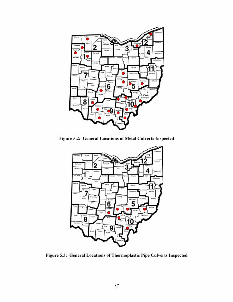
87
Figure 5.2: General Locations of Metal Culverts Inspected
Figure 5.3: General Locations of Thermoplastic Pipe Culverts Inspected
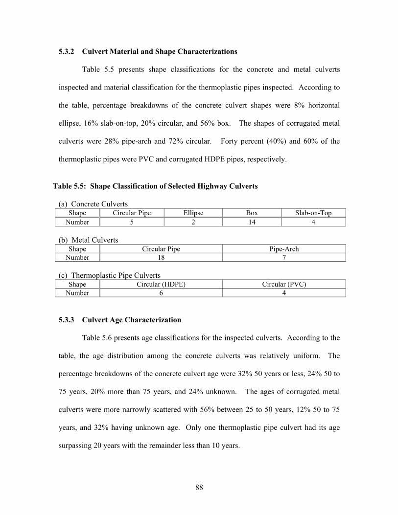
88
5.3.2 Culvert Material and Shape Characterizations
Table 5.5 presents shape classifications for the concrete and metal culverts
inspected and material classification for the thermoplastic pipes inspected. According to
the table, percentage breakdowns of the concrete culvert shapes were 8% horizontal
ellipse, 16% slab-on-top, 20% circular, and 56% box. The shapes of corrugated metal
culverts were 28% pipe-arch and 72% circular. Forty percent (40%) and 60% of the
thermoplastic pipes were PVC and corrugated HDPE pipes, respectively.
Table 5.5: Shape Classification of Selected Highway Culverts
(a) Concrete Culverts Shape Circular Pipe Ellipse Box Slab-on-Top
Number 5 2 14 4
(b) Metal Culverts Shape Circular Pipe Pipe-Arch
Number 18 7
(c) Thermoplastic Pipe Culverts Shape Circular (HDPE) Circular (PVC)
Number 6 4
5.3.3 Culvert Age Characterization
Table 5.6 presents age classifications for the inspected culverts. According to the
table, the age distribution among the concrete culverts was relatively uniform. The
percentage breakdowns of the concrete culvert age were 32% 50 years or less, 24% 50 to
75 years, 20% more than 75 years, and 24% unknown. The ages of corrugated metal
culverts were more narrowly scattered with 56% between 25 to 50 years, 12% 50 to 75
years, and 32% having unknown age. Only one thermoplastic pipe culvert had its age
surpassing 20 years with the remainder less than 10 years.
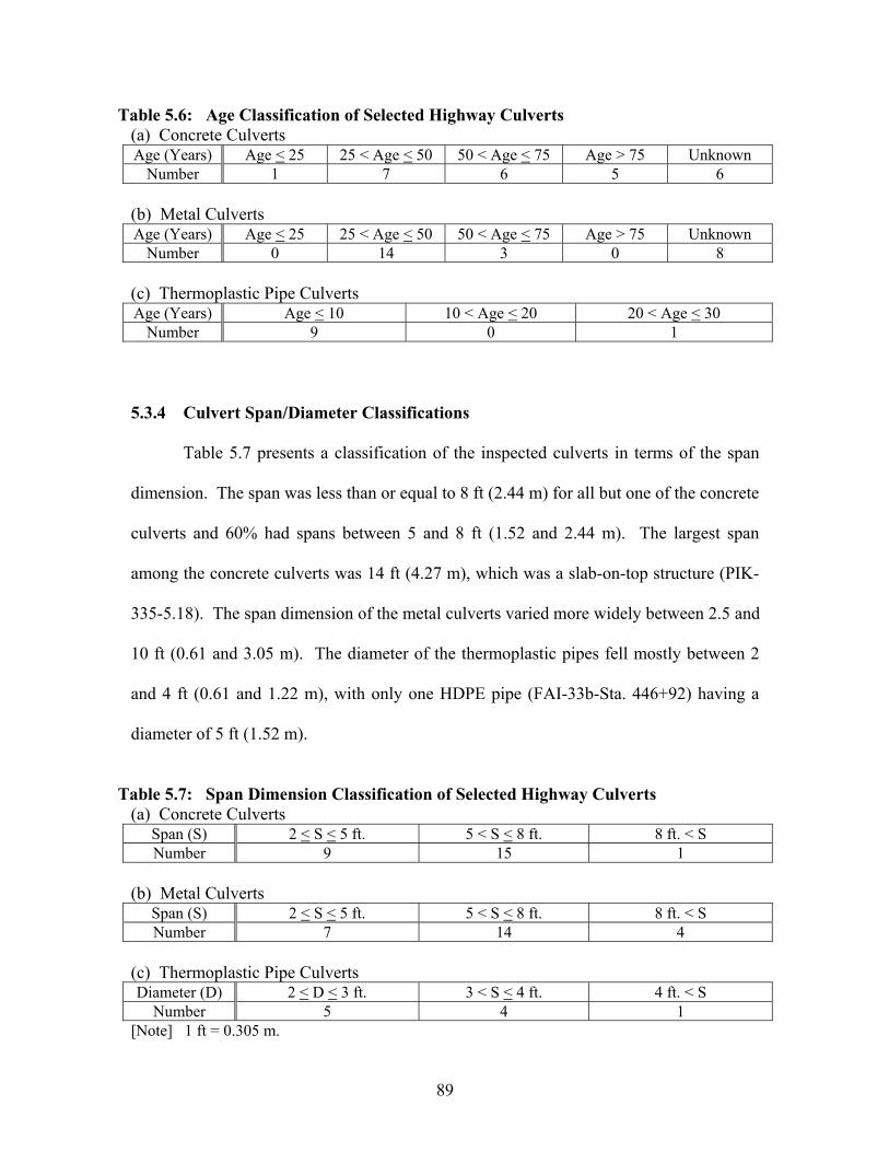
89
Table 5.6: Age Classification of Selected Highway Culverts (a) Concrete Culverts Age (Years) Age < 25 25 < Age < 50 50 < Age < 75 Age > 75 Unknown
Number 1 7 6 5 6
(b) Metal Culverts Age (Years) Age < 25 25 < Age < 50 50 < Age < 75 Age > 75 Unknown
Number 0 14 3 0 8
(c) Thermoplastic Pipe Culverts Age (Years) Age < 10 10 < Age < 20 20 < Age < 30
Number 9 0 1
5.3.4 Culvert Span/Diameter Classifications
Table 5.7 presents a classification of the inspected culverts in terms of the span
dimension. The span was less than or equal to 8 ft (2.44 m) for all but one of the concrete
culverts and 60% had spans between 5 and 8 ft (1.52 and 2.44 m). The largest span
among the concrete culverts was 14 ft (4.27 m), which was a slab-on-top structure (PIK-
335-5.18). The span dimension of the metal culverts varied more widely between 2.5 and
10 ft (0.61 and 3.05 m). The diameter of the thermoplastic pipes fell mostly between 2
and 4 ft (0.61 and 1.22 m), with only one HDPE pipe (FAI-33b-Sta. 446+92) having a
diameter of 5 ft (1.52 m).
Table 5.7: Span Dimension Classification of Selected Highway Culverts (a) Concrete Culverts
Span (S) 2 < S < 5 ft. 5 < S < 8 ft. 8 ft. < S Number 9 15 1
(b) Metal Culverts Span (S) 2 < S < 5 ft. 5 < S < 8 ft. 8 ft. < S Number 7 14 4
(c) Thermoplastic Pipe Culverts Diameter (D) 2 < D < 3 ft. 3 < S < 4 ft. 4 ft. < S
Number 5 4 1 [Note] 1 ft = 0.305 m.
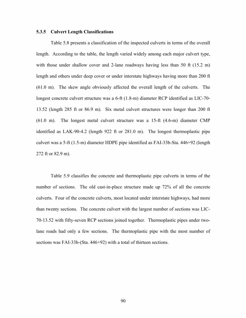
90
5.3.5 Culvert Length Classifications
Table 5.8 presents a classification of the inspected culverts in terms of the overall
length. According to the table, the length varied widely among each major culvert type,
with those under shallow cover and 2-lane roadways having less than 50 ft (15.2 m)
length and others under deep cover or under interstate highways having more than 200 ft
(61.0 m). The skew angle obviously affected the overall length of the culverts. The
longest concrete culvert structure was a 6-ft (1.8-m) diameter RCP identified as LIC-70-
13.52 (length 285 ft or 86.9 m). Six metal culvert structures were longer than 200 ft
(61.0 m). The longest metal culvert structure was a 15-ft (4.6-m) diameter CMP
identified as LAK-90-4.2 (length 922 ft or 281.0 m). The longest thermoplastic pipe
culvert was a 5-ft (1.5-m) diameter HDPE pipe identified as FAI-33b-Sta. 446+92 (length
272 ft or 82.9 m).
Table 5.9 classifies the concrete and thermoplastic pipe culverts in terms of the
number of sections. The old cast-in-place structure made up 72% of all the concrete
culverts. Four of the concrete culverts, most located under interstate highways, had more
than twenty sections. The concrete culvert with the largest number of sections was LIC-
70-13.52 with fifty-seven RCP sections joined together. Thermoplastic pipes under two-
lane roads had only a few sections. The thermoplastic pipe with the most number of
sections was FAI-33b-(Sta. 446+92) with a total of thirteen sections.

91
Table 5.8: Length Classification of Selected Highway Culverts (a) Concrete Culverts
Length (L) L < 50 ft. 50 < L < 100 ft. 100 < L < 200 ft. 200 ft. < L Number 12 9 2 2
(b) Metal Culverts Length (L) L < 50 ft. 50 < L < 100 ft. 100 < L < 200 ft. 200 ft. < L
Number 3 11 5 6
(c) Thermoplastic Pipe Culverts Length (L) L < 50 ft. 50 < L < 100 ft. 100 < L < 200 ft. 200 ft. < L
Number 2 3 4 1 [Note] 1 ft = 0.305 m.
Table 5.9: Culvert Classifications In Terms of Number of Sections (a) Concrete Culverts No. of Sections 1 (cast in-place) 2 to 10 11 to 20 > 20
Number 18 3 0 4
(b) Thermoplastic Pipe Culverts No. of Sections 2 to 4 5 to 10 11 to 15 > 15
Number 4 4 2 0
5.3.6 Soil Cover Height Characterization
Variations in the cover thickness (installation depth) among the inspected culverts
are summarized in Table 5.10. The majority (88%) of the concrete culverts had shallow
covers of less than or equal to 5 ft (1.5 m). None of the concrete culverts were installed
under more than 20 ft (6.1 m) of cover. On the contrary, 44% of the metal culverts were
under shallow coverts. And, 24% of the metal culverts were installed at least 20 ft (6.1 m)
deep. The maximum cover height for the metal culverts was 64 ft (19.5 m) found at the
site of MUS-93-1.76. Most of the thermoplastic pipes were installed below 20 ft (6.1 m)
of soil cover. The minimum cover height was 1.3 ft (0.4 m) at a 2-ft (0.61-m) diameter
HDPE pipe NOB-145-3.59, and the maximum cover height of 22 ft (6.7 m) was found
over a 3-ft (0.61-m) diameter PVC pipe FAI-22-Sta. 17+20.
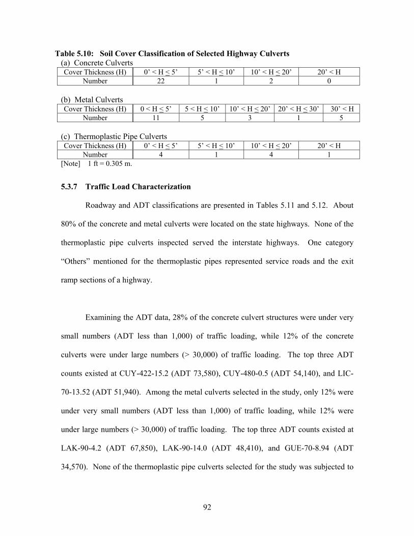
92
Table 5.10: Soil Cover Classification of Selected Highway Culverts (a) Concrete Culverts Cover Thickness (H) 0’ < H < 5’ 5’ < H < 10’ 10’ < H < 20’ 20’ < H
Number 22 1 2 0
(b) Metal Culverts Cover Thickness (H) 0 < H < 5’ 5 < H < 10’ 10’ < H < 20’ 20’ < H < 30’ 30’ < H
Number 11 5 3 1 5
(c) Thermoplastic Pipe Culverts Cover Thickness (H) 0’ < H < 5’ 5’ < H < 10’ 10’ < H < 20’ 20’ < H
Number 4 1 4 1 [Note] 1 ft = 0.305 m.
5.3.7 Traffic Load Characterization
Roadway and ADT classifications are presented in Tables 5.11 and 5.12. About
80% of the concrete and metal culverts were located on the state highways. None of the
thermoplastic pipe culverts inspected served the interstate highways. One category
“Others” mentioned for the thermoplastic pipes represented service roads and the exit
ramp sections of a highway.
Examining the ADT data, 28% of the concrete culvert structures were under very
small numbers (ADT less than 1,000) of traffic loading, while 12% of the concrete
culverts were under large numbers (> 30,000) of traffic loading. The top three ADT
counts existed at CUY-422-15.2 (ADT 73,580), CUY-480-0.5 (ADT 54,140), and LIC-
70-13.52 (ADT 51,940). Among the metal culverts selected in the study, only 12% were
under very small numbers (ADT less than 1,000) of traffic loading, while 12% were
under large numbers (> 30,000) of traffic loading. The top three ADT counts existed at
LAK-90-4.2 (ADT 67,850), LAK-90-14.0 (ADT 48,410), and GUE-70-8.94 (ADT
34,570). None of the thermoplastic pipe culverts selected for the study was subjected to

93
large numbers of traffic loading. Six percent (60%) of the thermoplastic pipe culverts
were installed at a major highway construction site in District 5 and were not yet
subjected to any constant traffic loading.
Table 5.11: Roadway Classification of Selected Highway Culverts (a) Concrete Culverts
Roadway Type Interstate Highway U.S. Highway State Highway Number 2 2 21
(b) Metal Culverts Roadway Type Interstate Highway U.S. Highway State Highway
Number 4 1 20
(c) Thermoplastic Pipe Culverts Roadway Type Interstate Highway U.S. Highway State Highway Others
Number 0 3 4 3
Table 5.12: ADT Classification of Selected Highway Culverts (a) Concrete Culverts
ADT < 1,000 1,000 to 4,000 4,000 to 10,000 10,000 to 30,000 > 30,000 Number 7 13 2 0 3
(b) Metal Culverts ADT < 1,000 1,000 to 4,000 4,000 to 10,000 10,000 to 30,000 > 30,000
Number 3 11 5 3 3 [Note] The ADT data were not readily available for the thermoplastic pipe culvert sites.
5.3.8 Environmental Condition Characterization
Key environmental conditions at highway culvert sites, such as pH of drainage
water and abrasiveness of the flow, were summarized in a series of charts in the ODOT
culvert durability study report (ODOT 1982). By consulting these charts, basic
environmental site characterization can be obtained. Results are presented in Table 5.13.
According to the table, only one (4%) of the concrete culverts was supposed to be
regularly impacted by acidic drainage, while abrasive bed material can be present at up to
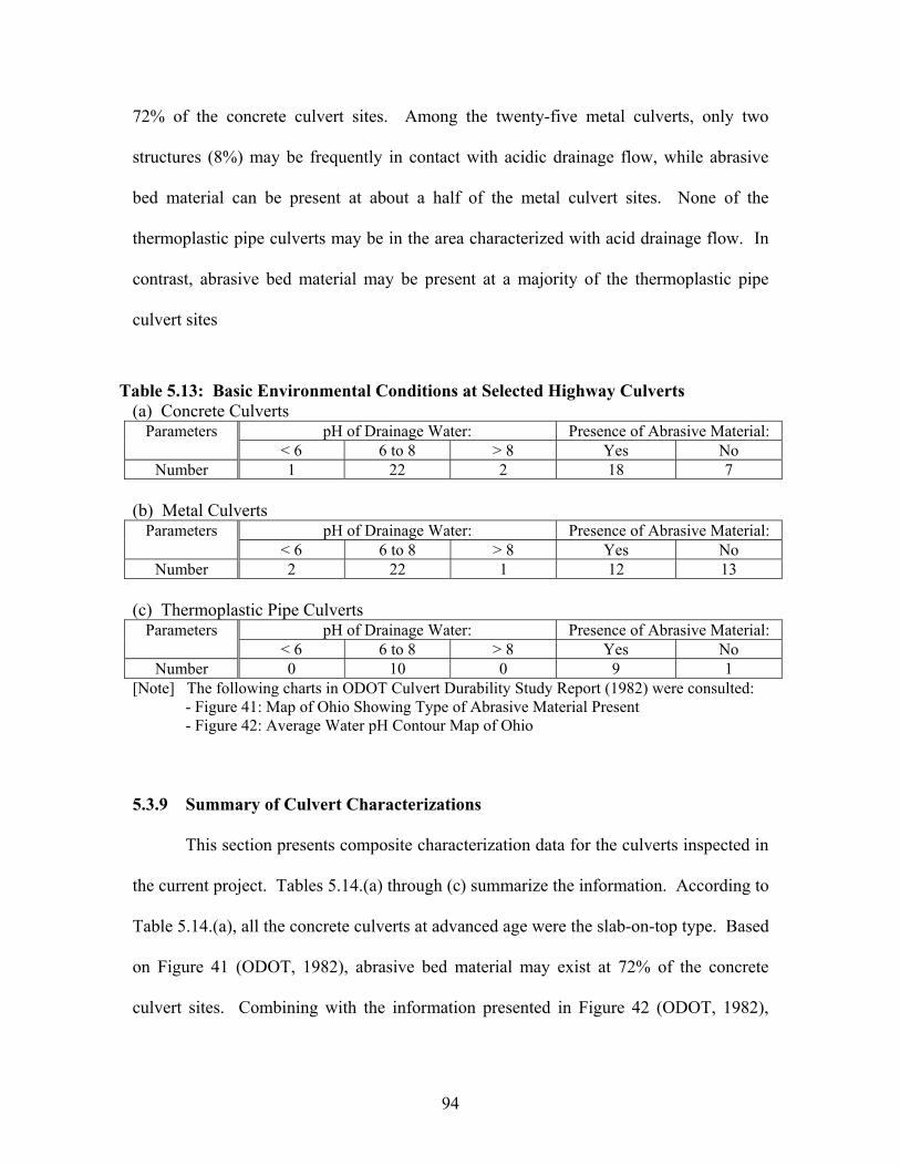
94
72% of the concrete culvert sites. Among the twenty-five metal culverts, only two
structures (8%) may be frequently in contact with acidic drainage flow, while abrasive
bed material can be present at about a half of the metal culvert sites. None of the
thermoplastic pipe culverts may be in the area characterized with acid drainage flow. In
contrast, abrasive bed material may be present at a majority of the thermoplastic pipe
culvert sites
Table 5.13: Basic Environmental Conditions at Selected Highway Culverts (a) Concrete Culverts
pH of Drainage Water: Presence of Abrasive Material: Parameters< 6 6 to 8 > 8 Yes No
Number 1 22 2 18 7
(b) Metal Culverts pH of Drainage Water: Presence of Abrasive Material: Parameters
< 6 6 to 8 > 8 Yes No Number 2 22 1 12 13
(c) Thermoplastic Pipe Culverts pH of Drainage Water: Presence of Abrasive Material: Parameters
< 6 6 to 8 > 8 Yes No Number 0 10 0 9 1
[Note] The following charts in ODOT Culvert Durability Study Report (1982) were consulted: - Figure 41: Map of Ohio Showing Type of Abrasive Material Present - Figure 42: Average Water pH Contour Map of Ohio
5.3.9 Summary of Culvert Characterizations
This section presents composite characterization data for the culverts inspected in
the current project. Tables 5.14.(a) through (c) summarize the information. According to
Table 5.14.(a), all the concrete culverts at advanced age were the slab-on-top type. Based
on Figure 41 (ODOT, 1982), abrasive bed material may exist at 72% of the concrete
culvert sites. Combining with the information presented in Figure 42 (ODOT, 1982),

95
only one structure is supposed to be subjected to acidic and possibly abrasive drainage
flow. All of the advanced-age concrete culvert structures were under shallow covers.
According to Table 5.14.(b), pipe-arch structures are located in Districts 1, 8, 9,
and 10. Most of the circular metal pipe culverts were at ages between 40 and 60 years.
Referring to Figure 41 (ODOT, 1982), abrasive bed material may be present at about half
(48%) of the metal culvert sites. And, the metal culvert may be often subjected to acid
drainage at three of these sites. Both of the advanced-age metal culvert structures were
under shallow covers. The metal culverts with age between 40 and 60 years were under a
wide range of soil cover thickness.
According to Table 5.14.(c), only one of the six HDPE pipes was older than 20
years and none of the four PVC pipes were older than 20 years. Based on Figure 41
(ODOT, 1982), abrasive bed material may be present at most of the sites. However, six of
the ten sites are situated within a major highway construction project area. Construction
activities can alter the original environmental conditions. Based on Figure 42 (ODOT,
1982), none of the structures are supposed to be normally subjected to acidic drainage.
The flow condition was judged abrasive at only one of these HDPE pipe culvert sites.
The 23-year old HDPE pipe culvert (NOB-145-3.59) had been serving under abrasive
drainage flow and shallow cover.
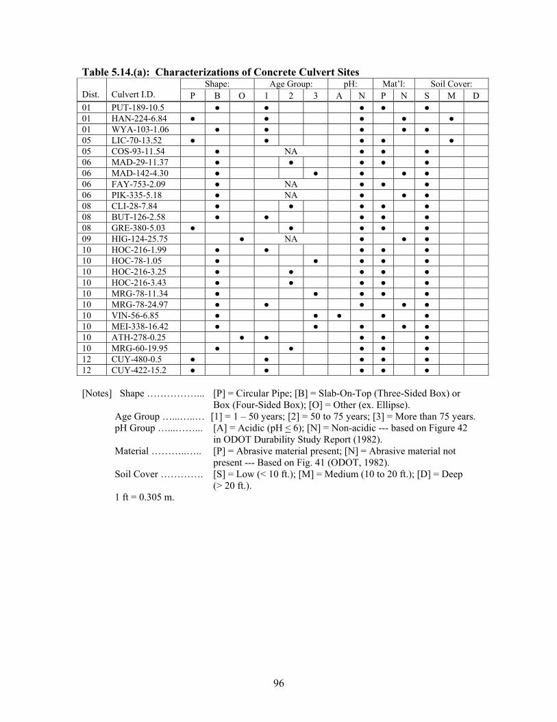
96
Table 5.14.(a): Characterizations of Concrete Culvert Sites Shape: Age Group: pH: Mat’l: Soil Cover:
Dist. Culvert I.D. P B O 1 2 3 A N P N S M D01 PUT-189-10.5 01 HAN-224-6.84 01 WYA-103-1.06 05 LIC-70-13.52 05 COS-93-11.54 NA06 MAD-29-11.37 06 MAD-142-4.30 06 FAY-753-2.09 NA06 PIK-335-5.18 NA08 CLI-28-7.84 08 BUT-126-2.58 08 GRE-380-5.03 09 HIG-124-25.75 NA10 HOC-216-1.99 10 HOC-78-1.05 10 HOC-216-3.25 10 HOC-216-3.43 10 MRG-78-11.34 10 MRG-78-24.97 10 VIN-56-6.85 10 MEI-338-16.42 10 ATH-278-0.25 10 MRG-60-19.95 12 CUY-480-0.5 12 CUY-422-15.2
[Notes] Shape ……………... [P] = Circular Pipe; [B] = Slab-On-Top (Three-Sided Box) or Box (Four-Sided Box); [O] = Other (ex. Ellipse). Age Group …...…..… [1] = 1 – 50 years; [2] = 50 to 75 years; [3] = More than 75 years. pH Group …...……... [A] = Acidic (pH < 6); [N] = Non-acidic --- based on Figure 42 in ODOT Durability Study Report (1982). Material ………..….. [P] = Abrasive material present; [N] = Abrasive material not present --- Based on Fig. 41 (ODOT, 1982). Soil Cover …………. [S] = Low (< 10 ft.); [M] = Medium (10 to 20 ft.); [D] = Deep (> 20 ft.). 1 ft = 0.305 m.
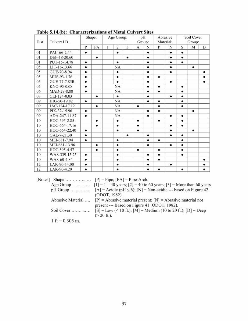
97
Table 5.14.(b): Characterizations of Metal Culvert Sites Shape: Age Group: pH
Group: Abrasive Material:
Soil Cover Group: Dist. Culvert I.D.
P PA 1 2 3 A N P N S M D01 PAU-66-2.44 01 DEF-18-20.60 01 PUT-15-14.78 05 LIC-16-13.66 NA05 GUE-70-8.94 05 MUS-93-1.76 05 GUE-77-7.85R 05 KNO-95-0.08 NA 06 MAD-29-8.80 NA 08 CLI-124-0.03 09 HIG-50-19.82 NA 09 JAC-124-17.12 NA 09 PIK-32-15.96 NA 09 ADA-247-11.87 NA 10 HOC-595-2.85 10 HOC-664-17.16 10 HOC-664-22.40 10 GAL-7-21.30 10 MEI-681-7.94 10 MEI-681-13.96 10 HOC-595-4.57 10 WAS-339-15.25 10 WAS-60-4.84 12 LAK-90-14.00 12 LAK-90-4.20
[Notes] Shape …………...… [P] = Pipe; [PA] = Pipe-Arch. Age Group …...….… [1] = 1 – 40 years; [2] = 40 to 60 years; [3] = More than 60 years. pH Group …...….….. [A] = Acidic (pH < 6); [N] = Non-acidic --- based on Figure 42 (ODOT, 1982). Abrasive Material …. [P] = Abrasive material present; [N] = Abrasive material not present --- Based on Figure 41 (ODOT, 1982). Soil Cover ……....…. [S] = Low (< 10 ft.); [M] = Medium (10 to 20 ft.); [D] = Deep (> 20 ft.). 1 ft = 0.305 m.
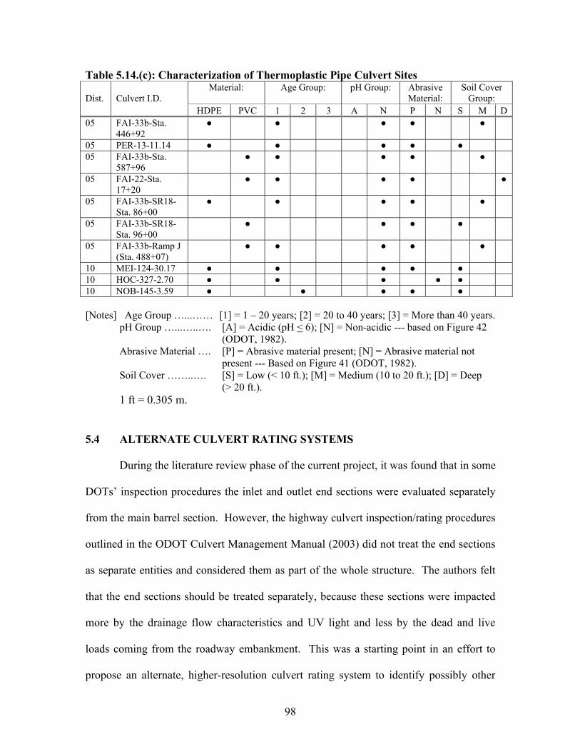
98
Table 5.14.(c): Characterization of Thermoplastic Pipe Culvert Sites Material: Age Group: pH Group: Abrasive
Material:Soil Cover
Group: Dist. Culvert I.D. HDPE PVC 1 2 3 A N P N S M D
05 FAI-33b-Sta. 446+92
05 PER-13-11.14 05 FAI-33b-Sta.
587+96
05 FAI-22-Sta. 17+20
05 FAI-33b-SR18-Sta. 86+00
05 FAI-33b-SR18-Sta. 96+00
05 FAI-33b-Ramp J (Sta. 488+07)
10 MEI-124-30.17 10 HOC-327-2.70 10 NOB-145-3.59
[Notes] Age Group …...…… [1] = 1 – 20 years; [2] = 20 to 40 years; [3] = More than 40 years. pH Group …...…..…. [A] = Acidic (pH < 6); [N] = Non-acidic --- based on Figure 42 (ODOT, 1982). Abrasive Material …. [P] = Abrasive material present; [N] = Abrasive material not present --- Based on Figure 41 (ODOT, 1982). Soil Cover ……..…. [S] = Low (< 10 ft.); [M] = Medium (10 to 20 ft.); [D] = Deep (> 20 ft.). 1 ft = 0.305 m.
5.4 ALTERNATE CULVERT RATING SYSTEMS
During the literature review phase of the current project, it was found that in some
DOTs’ inspection procedures the inlet and outlet end sections were evaluated separately
from the main barrel section. However, the highway culvert inspection/rating procedures
outlined in the ODOT Culvert Management Manual (2003) did not treat the end sections
as separate entities and considered them as part of the whole structure. The authors felt
that the end sections should be treated separately, because these sections were impacted
more by the drainage flow characteristics and UV light and less by the dead and live
loads coming from the roadway embankment. This was a starting point in an effort to
propose an alternate, higher-resolution culvert rating system to identify possibly other

99
important needed inspection items. The alternate system can be viewed as an enhanced
version of the new culvert rating system developed by ODOT (ODOT, 2003).
In the proposed high-resolution system, a complete set of inspection data for any
culvert structure is grouped into inventory data, primary data, and secondary data. Items
within the inventory or background data are those that can be obtained from a district
office as background information and can be used to locate the structure in the field. The
primary and secondary data were collected during the actual field inspection work
conducted at the culvert site. Items in the primary data indicate directly the existing
conditions of the culvert structure. Items in the secondary data reflect the conditions of
the structures/features (such as headwalls, embankment slopes, …) surrounding the
culvert and serve as indirect measures of the culvert performance. Tables 5.15 through
5.17 present the complete set of data required for inspecting concrete, metal, and
thermoplastic pipe culverts, respectively. The items in the primary data differ somewhat
from one type of culvert to another. Appendices B through D contain copies of the field
inspection date sheets used for concrete, metal, and thermoplastic pipe culverts,
respectively.
Table 5.15: ORITE Data Collection for Concrete Culverts (a) Inventory Data
Location (District, County, Roadway, Straight Line Mileage, …). Culvert Material Age (Year Built) Type of Protective Coating Shape Rise Span Length Wall Thickness No. of Cells No. of Joints Slope Max. Height of Cover Skew Angle Inlet End Treatment Outlet End Treatment Hydraulic Capacity Channel Protection ADT Modifications Past Inspection & Maintenance Records
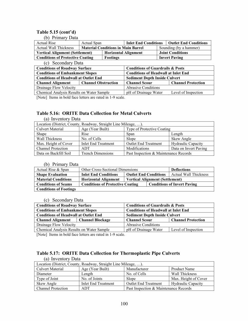
100
Table 5.15 (cont’d) (b) Primary Data
Actual Rise Actual Span Inlet End Conditions Outlet End Conditions Actual Wall Thickness Material Conditions in Main Barrel Sounding (by a hammer) Vertical Alignment (Settlement) Horizontal Alignment Joint Conditions Conditions of Protective Coating Footings Invert Paving
(c) Secondary Data Conditions of Roadway Surface Conditions of Guardrails & Posts Conditions of Embankment Slopes Conditions of Headwall at Inlet End Conditions of Headwall at Outlet End Sediment Depth Inside Culvert Channel Alignment Channel Obstruction Channel Scour Channel Protection Drainage Flow Velocity Abrasive Conditions Chemical Analysis Results on Water Sample pH of Drainage Water Level of Inspection [Note] Items in bold face letters are rated in 1-9 scale.
Table 5.16: ORITE Data Collection for Metal Culverts(a) Inventory Data
Location (District, County, Roadway, Straight Line Mileage, …). Culvert Material Age (Year Built) Type of Protective Coating Shape Rise Span Length Wall Thickness No. of Cells Slope Skew Angle Max. Height of Cover Inlet End Treatment Outlet End Treatment Hydraulic Capacity Channel Protection ADT Modifications Data on Invert Paving Data on Backfill Soil Trench Dimensions Past Inspection & Maintenance Records
(b) Primary Data Actual Rise & Span Other Cross-Sectional Dimensions Deflections Shape Evaluation Inlet End Conditions Outlet End Conditions Actual Wall Thickness Material Conditions Horizontal Alignment Vertical Alignment (Settlement) Conditions of Seams Conditions of Protective Coating Conditions of Invert Paving Conditions of Footings
(c) Secondary Data Conditions of Roadway Surface Conditions of Guardrails & Posts Conditions of Embankment Slopes Conditions of Headwall at Inlet End Conditions of Headwall at Outlet End Sediment Depth Inside Culvert Channel Alignment Channel Blockage Channel Scour Channel Protection Drainage Flow Velocity Abrasive Conditions Chemical Analysis Results on Water Sample pH of Drainage Water Level of Inspection [Note] Items in bold face letters are rated in 1-9 scale.
Table 5.17: ORITE Data Collection for Thermoplastic Pipe Culverts (a) Inventory Data
Location (District, County, Roadway, Straight Line Mileage, …). Culvert Material Age (Year Built) Manufacturer Product Name Diameter Length No. of Cells Wall Thickness Type of Joint No. of Joints Slope Max. Height of Cover Skew Angle Inlet End Treatment Outlet End Treatment Hydraulic Capacity Channel Protection ADT Past Inspection & Maintenance Records

101
Table 5.17 (cont’d) (b) Primary Data
Actual Rise & Span Other Cross-Sectional Dimensions Deflections Shape Evaluation Inlet End Conditions Outlet End Conditions Actual Wall Thickness Material Conditions Horizontal Alignment Vertical Alignment (Settlement) Conditions of Joints
(c) Secondary Data Conditions of Roadway Surface Conditions of Guardrails & Posts Conditions of Embankment Slopes Conditions of Headwall at Inlet End Conditions of Headwall at Outlet End Sediment Depth Inside Culvert Channel Alignment Channel Blockage Channel Scour Channel Protection Drainage Flow Velocity Abrasive Conditions Chemical Analysis Results on Water Sample pH of Drainage Water Level of Inspection [Note] Items in bold face letters are rated in 1-9 scale.
There are many similarities between the ODOT and the proposed systems in
rating these items. Also, there are clear differences, besides the separate evaluation of
culvert ends. Table 5.18 summarizes the similarities and differences between the two
culvert rating systems. The proposed system aims for higher resolutions in the data
collected in the field by:
- Rating the general material conditions in each distinct region (crown, sides,
invert) of the culvert.
- Rating the conditions at the joints/seams in each distinct region (crown, sides,
invert) of the culvert.
- Rating the conditions of each headwall in terms of cracking, deterioration, and
movement.
Tables 5.19 through 5.23 are added here to further illustrate the degree of high
resolution that the proposed system employed. This resolution includes rating of the
protective coating and invert paving (Table 5.19), the culvert inlet and outlet sections
(Table 5.20), footings (Table 5.21), headwalls/wingwalls (Table 5.22), and channel
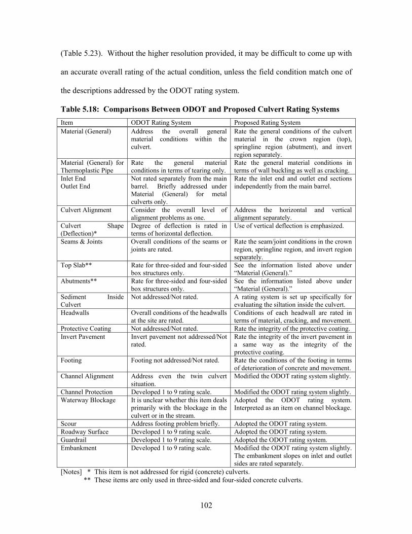
102
(Table 5.23). Without the higher resolution provided, it may be difficult to come up with
an accurate overall rating of the actual condition, unless the field condition match one of
the descriptions addressed by the ODOT rating system.
Table 5.18: Comparisons Between ODOT and Proposed Culvert Rating Systems
Item ODOT Rating System Proposed Rating System Material (General) Address the overall general
material conditions within the culvert.
Rate the general conditions of the culvert material in the crown region (top), springline region (abutment), and invert region separately.
Material (General) for Thermoplastic Pipe
Rate the general material conditions in terms of tearing only.
Rate the general material conditions in terms of wall buckling as well as cracking.
Inlet End Outlet End
Not rated separately from the main barrel. Briefly addressed under Material (General) for metal culverts only.
Rate the inlet end and outlet end sections independently from the main barrel.
Culvert Alignment Consider the overall level of alignment problems as one.
Address the horizontal and vertical alignment separately.
Culvert Shape (Deflection)*
Degree of deflection is rated in terms of horizontal deflection.
Use of vertical deflection is emphasized.
Seams & Joints Overall conditions of the seams or joints are rated.
Rate the seam/joint conditions in the crown region, springline region, and invert region separately.
Top Slab** Rate for three-sided and four-sided box structures only.
See the information listed above under “Material (General).”
Abutments** Rate for three-sided and four-sided box structures only.
See the information listed above under “Material (General).”
Sediment Inside Culvert
Not addressed/Not rated. A rating system is set up specifically for evaluating the siltation inside the culvert.
Headwalls Overall conditions of the headwalls at the site are rated.
Conditions of each headwall are rated in terms of material, cracking, and movement.
Protective Coating Not addressed/Not rated. Rate the integrity of the protective coating. Invert Pavement Invert pavement not addressed/Not
rated.Rate the integrity of the invert pavement in a same way as the integrity of the protective coating.
Footing Footing not addressed/Not rated. Rate the conditions of the footing in terms of deterioration of concrete and movement.
Channel Alignment Address even the twin culvert situation.
Modified the ODOT rating system slightly.
Channel Protection Developed 1 to 9 rating scale. Modified the ODOT rating system slightly. Waterway Blockage It is unclear whether this item deals
primarily with the blockage in the culvert or in the stream.
Adopted the ODOT rating system. Interpreted as an item on channel blockage.
Scour Address footing problem briefly. Adopted the ODOT rating system. Roadway Surface Developed 1 to 9 rating scale. Adopted the ODOT rating system. Guardrail Developed 1 to 9 rating scale. Adopted the ODOT rating system. Embankment Developed 1 to 9 rating scale. Modified the ODOT rating system slightly.
The embankment slopes on inlet and outlet sides are rated separately.
[Notes] * This item is not addressed for rigid (concrete) culverts. ** These items are only used in three-sided and four-sided concrete culverts.
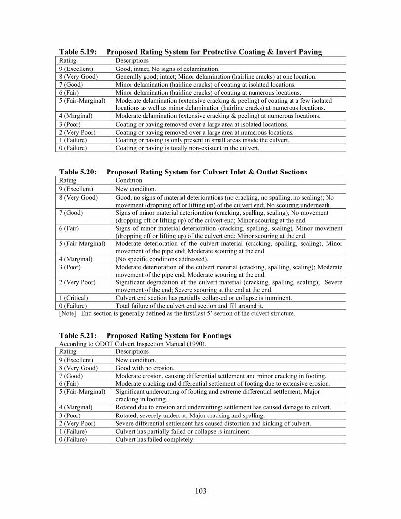
103
Table 5.19: Proposed Rating System for Protective Coating & Invert Paving Rating Descriptions 9 (Excellent) Good, intact; No signs of delamination. 8 (Very Good) Generally good; intact; Minor delamination (hairline cracks) at one location. 7 (Good) Minor delamination (hairline cracks) of coating at isolated locations. 6 (Fair) Minor delamination (hairline cracks) of coating at numerous locations. 5 (Fair-Marginal) Moderate delamination (extensive cracking & peeling) of coating at a few isolated
locations as well as minor delamination (hairline cracks) at numerous locations. 4 (Marginal) Moderate delamination (extensive cracking & peeling) at numerous locations. 3 (Poor) Coating or paving removed over a large area at isolated locations. 2 (Very Poor) Coating or paving removed over a large area at numerous locations. 1 (Failure) Coating or paving is only present in small areas inside the culvert. 0 (Failure) Coating or paving is totally non-existent in the culvert.
Table 5.20: Proposed Rating System for Culvert Inlet & Outlet SectionsRating Condition 9 (Excellent) New condition. 8 (Very Good) Good, no signs of material deteriorations (no cracking, no spalling, no scaling); No
movement (dropping off or lifting up) of the culvert end; No scouring underneath. 7 (Good) Signs of minor material deterioration (cracking, spalling, scaling); No movement
(dropping off or lifting up) of the culvert end; Minor scouring at the end. 6 (Fair) Signs of minor material deterioration (cracking, spalling, scaling), Minor movement
(dropping off or lifting up) of the culvert end; Minor scouring at the end. 5 (Fair-Marginal) Moderate deterioration of the culvert material (cracking, spalling, scaling), Minor
movement of the pipe end; Moderate scouring at the end. 4 (Marginal) (No specific conditions addressed). 3 (Poor) Moderate deterioration of the culvert material (cracking, spalling, scaling); Moderate
movement of the pipe end; Moderate scouring at the end. 2 (Very Poor) Significant degradation of the culvert material (cracking, spalling, scaling); Severe
movement of the end; Severe scouring at the end at the end. 1 (Critical) Culvert end section has partially collapsed or collapse is imminent. 0 (Failure) Total failure of the culvert end section and fill around it. [Note] End section is generally defined as the first/last 5’ section of the culvert structure.
Table 5.21: Proposed Rating System for Footings According to ODOT Culvert Inspection Manual (1990). Rating Descriptions 9 (Excellent) New condition. 8 (Very Good) Good with no erosion. 7 (Good) Moderate erosion, causing differential settlement and minor cracking in footing. 6 (Fair) Moderate cracking and differential settlement of footing due to extensive erosion. 5 (Fair-Marginal) Significant undercutting of footing and extreme differential settlement; Major
cracking in footing. 4 (Marginal) Rotated due to erosion and undercutting; settlement has caused damage to culvert. 3 (Poor) Rotated; severely undercut; Major cracking and spalling. 2 (Very Poor) Severe differential settlement has caused distortion and kinking of culvert. 1 (Failure) Culvert has partially failed or collapse is imminent. 0 (Failure) Culvert has failed completely.
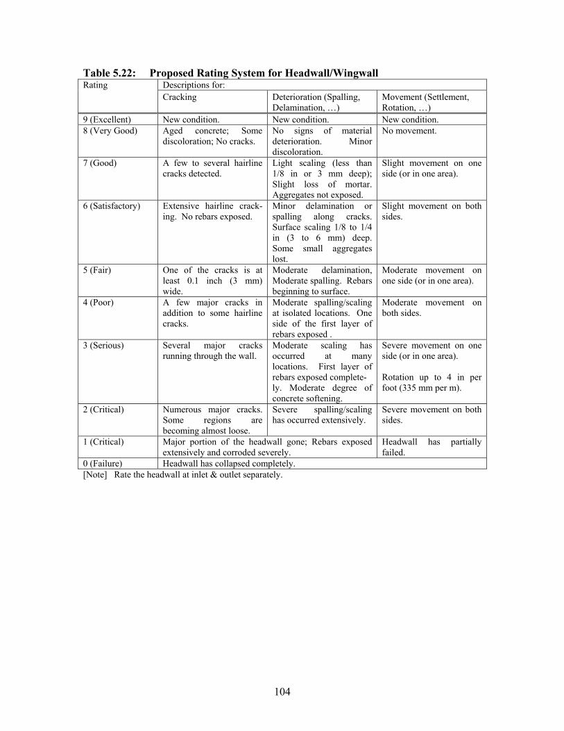
104
Table 5.22: Proposed Rating System for Headwall/WingwallDescriptions for: Rating Cracking Deterioration (Spalling,
Delamination, …) Movement (Settlement, Rotation, …)
9 (Excellent) New condition. New condition. New condition. 8 (Very Good) Aged concrete; Some
discoloration; No cracks. No signs of material deterioration. Minor discoloration.
No movement.
7 (Good) A few to several hairline cracks detected.
Light scaling (less than 1/8 in or 3 mm deep); Slight loss of mortar. Aggregates not exposed.
Slight movement on one side (or in one area).
6 (Satisfactory) Extensive hairline crack-ing. No rebars exposed.
Minor delamination or spalling along cracks. Surface scaling 1/8 to 1/4 in (3 to 6 mm) deep. Some small aggregates lost.
Slight movement on both sides.
5 (Fair) One of the cracks is at least 0.1 inch (3 mm) wide.
Moderate delamination, Moderate spalling. Rebars beginning to surface.
Moderate movement on one side (or in one area).
4 (Poor) A few major cracks in addition to some hairline cracks.
Moderate spalling/scaling at isolated locations. One side of the first layer of rebars exposed .
Moderate movement on both sides.
3 (Serious) Several major cracks running through the wall.
Moderate scaling has occurred at many locations. First layer of rebars exposed complete- ly. Moderate degree of concrete softening.
Severe movement on one side (or in one area).
Rotation up to 4 in per foot (335 mm per m).
2 (Critical) Numerous major cracks. Some regions are becoming almost loose.
Severe spalling/scaling has occurred extensively.
Severe movement on both sides.
1 (Critical) Major portion of the headwall gone; Rebars exposed extensively and corroded severely.
Headwall has partially failed.
0 (Failure) Headwall has collapsed completely. [Note] Rate the headwall at inlet & outlet separately.
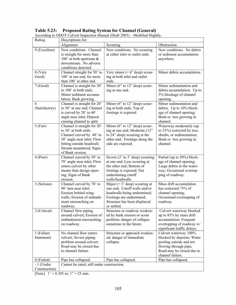
105
Table 5.23: Proposed Rating System for Channel (General) According to ODOT Culvert Inspection Manual (Draft 2003) – Modified Slightly.
Descriptions for: Rating Alignment Scouring Obstruction
9 (Excellent) New conditions. Channel is straight for more than 100’ at both upstream & downstream. No adverse conditions detected.
New conditions. No scouring at either inlet or outlet ends.
New conditions. No debris or sediment accumulation anywhere.
8 (Very Good)
Channel straight for 50’ to 100’ at one end, for more than 100’ at other end.
Very minor (< 6” deep) scour-ing at both inlet and outlet ends.
Minor debris accumulation.
7 (Good) Channel is straight for 50’ to 100’ at both ends; Minor sediment accumu-lation; Bush growing.
Minor (6” to 12” deep) scour-ing at one end.
Minor sedimentation and debris accumulation; Up to 5% blockage of channel opening.
6(Satisfactory)
Channel is straight for 20’ to 50’ at one end; Channel is curved by 20˚ to 40˚angle near inlet; Deposit causing channel to split.
Minor (6” to 12” deep) scour-ing at both ends; Top of footings is exposed.
Minor sedimentation and debris. Up to 10% block-age of channel opening; Bush or tree growing in channel.
5 (Fair) Channel is straight for 20’ to 50’ at both ends; Channel curved by 40˚ to 50˚ angle near inlet; Flow hitting outside headwall; Stream meandered; Signs of Bank erosion.
Minor (6” to 12” deep) scour-ing at one end; Moderate (12” to 24” deep) scouring at the other end; Footings along the side are exposed.
Waterway moderately (up to 25%) restricted by tree, shrubs, or sedimentation; Bush or tree growing in channel.
4 (Poor) Channel curved by 50˚ to 70˚ angle near inlet; Flow enters culvert by other means than design open-ing; Signs of Bank erosion.
Severe (2’ to 3’ deep) scouring at one end; Less scouring at the other end; Bottom of footings is exposed; Not undermining cutoff walls/headwalls.
Partial (up to 50%) block-age of channel opening; Large debris in the water-way; Occasional overtop-ping of roadway.
3 (Serious) Channel curved by 70˚ to 90˚ turn near inlet; Erosion behind wing-walls; Erosion of embank-ment encroaching on roadway.
Major (> 3’ deep) scouring at one end; Cutoff walls and/or headwalls being undermined; Footings are undermined; Structure has been displaced or settled.
Mass drift accumulation has restricted 75% of channel opening; Occasional overtopping of roadway.
2 (Critical) Channel flow piping around culvert; Erosion of embankment encroaching on roadway.
Structure or roadway weaken-ed by bank erosion or scour problem; danger of collapse sometime in the future.
Culvert waterway blocked up to 85% by mass drift accumulation; Frequent overtopping of roadway w/ significant traffic delays.
1 (Failure Imminent)
No channel flow enters culvert; Severe piping problem around culvert; Road may be closed due to channel failure.
Structure or approach weaken-ed; danger of immediate collapse.
Culvert waterway 100% blocked by deposits; Water pooling outside and not flowing through pipe; Road may be closed due to channel failure.
0 (Failed) Pipe has collapsed. Pipe has collapsed. Pipe has collapsed. - 1 (Under Construction)
Cannot be rated; still under construction.
[Note] 1’ = 0.305 m; 1” = 25 mm.

106
5.5 FIELD INSPECTION PROGRAM
5.5.1 Inspection Team
The core of the field culvert inspection team comprised of two personnel from
ORITE and two personnel from the Subcontractor (Jobes Henderson & Associates). The
ORITE personnel had some prior culvert inspection experience as well as an in-depth
research (field instrumentation and monitoring, theoretical/numerical analysis)
experience related to corrugated metal culverts, concrete pipes, and thermoplastic pipes.
The Subcontractor brought more industry-oriented experience in culvert/bridge
inspections and design work. During the course of the project, an unanticipated
personnel change occurred once with the Subcontractor. However, the same core ORITE
personnel remained in the team throughout the entire inspection phase and visited and
evaluated all sixty culvert sites.
5.5.2 List of Equipment
Equipment the inspection team utilized in the field can be grouped into general
items (which are readily available and used routinely in every culvert inspection) and
specialized items (which may be used only at selected culvert sites). Table 5.24.(a) lists
the general items. The laser distance meter was useful in obtaining the total length of any
long culvert structure. The surveyor’s level rod was used to estimate the height of soil
cover. The hand-level was used to judge if the headwalls were tilted or not. The road
signs were posted along the traffic lane(s) in each direction to alert motorists that the field
inspection work was in progress. The micrometer was used to measure the wall thickness
of metal plates. Water pH-meter provided the pH reading of the drainage water at the

107
culvert inlet. The C-clamps, strings, and folding ruler were used to obtain detailed cross-
sectional dimensions. Table 5.24.(b) lists the specialized items. A water DO meter was
used to measure the dissolved oxygen level in the drainage flow. The team transported
the remote video inspection system whenever they were scheduled to inspect culverts that
were less than 4’ in rise.
Table 5.24: List of Field Equipment (a) General Items
Road Map Directional Compass Hip-boots Hard Hats Safety Vests Cell Phone Gloves Flash Lights Camera (Digital) Clipboard Data Sheets Pens ODOT Culvert Manual Road Signs 25’ Measuring Tape (Steel) Laser Distance Meter 100’ Tape (Fiberglass) Folding Ruler (Wooden) Survey Level Rod Hand Level Micrometer Chipping Hammer Plumb-bob C-Clamps Wire & Strings Shovels Steel Rod Spray Pain & Magic Marker Duct Tape Step Ladder Water Sample Bottles Extra Batteries First Aid Kit Water pH Meter Extension Cord Water Sample Bottles
(b) Specialized Items Water DO Analyzer Digital Thermometer Portable GPS Device Soil Sampler Skate Board Power Drill Power Generator Hole Saws & Drill Bits Electric Fan --- Remote Video Inspection System
5.5.3 Field Inspection Method
Typically, about one week prior to each inspection the team members identified
the next inspection date and exchanged inventory data (location, type, size, age, length,
soil cover, maintenance notes, …) on a couple of target culverts selected from the pool of
sixty structures. As needed, the team notified the DOT and other officials about their
field inspection schedule. As the inspection date approached, the members closely
108
monitored the weather and roadway condition data for the area where the culverts were
located. Inspection work at a culvert site typically proceeded as follows:
1) Confirm the type, size, and location of the culvert structure.
2) Set up the roadway signs for each traffic direction.
3) Assess basic environmental conditions (pH, DO, flow velocity, abrasiveness of
the flow) of the drainage flow and the channel at the inlet end. Take
photographs of the channel. Obtain a bottle sample of the drainage flow at culvert
inlet for lab analysis.
4) Rate the headwall, embankment slope, and culvert end (the first 5-ft. section from
the inlet end) while in the culvert inlet area. Take photographs of each of these
inspection items.
5) Walk over the entire barrel section of the culvert. Measure the total length of the
structure. Observe conditions of the material surface, seams/joints, sedimentation.
If the structure is long, divide the structure into sections. Rate the conditions
of the structure in each section.
6) Take cross-sectional shape measurements inside the culvert for metal and
thermoplastic pipe culverts. (see Table 5.25 and Figure 5.4 for measurement
types).
7) Assess the horizontal and vertical alignments, while walking toward the outlet end.
8) Rate the headwall, embankment slope, and culvert end (the last 5-ft. section from
the inlet end) while in the culvert outlet area. Take photographs of each of these
inspection items.
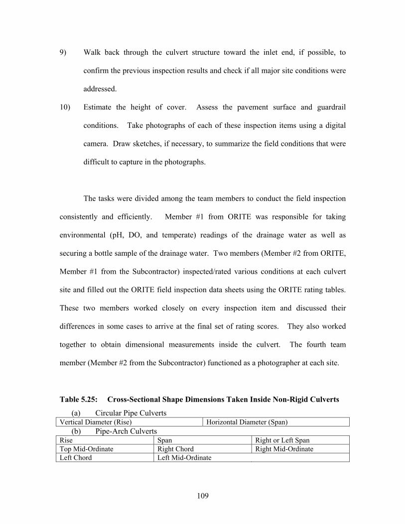
109
9) Walk back through the culvert structure toward the inlet end, if possible, to
confirm the previous inspection results and check if all major site conditions were
addressed.
10) Estimate the height of cover. Assess the pavement surface and guardrail
conditions. Take photographs of each of these inspection items using a digital
camera. Draw sketches, if necessary, to summarize the field conditions that were
difficult to capture in the photographs.
The tasks were divided among the team members to conduct the field inspection
consistently and efficiently. Member #1 from ORITE was responsible for taking
environmental (pH, DO, and temperate) readings of the drainage water as well as
securing a bottle sample of the drainage water. Two members (Member #2 from ORITE,
Member #1 from the Subcontractor) inspected/rated various conditions at each culvert
site and filled out the ORITE field inspection data sheets using the ORITE rating tables.
These two members worked closely on every inspection item and discussed their
differences in some cases to arrive at the final set of rating scores. They also worked
together to obtain dimensional measurements inside the culvert. The fourth team
member (Member #2 from the Subcontractor) functioned as a photographer at each site.
Table 5.25: Cross-Sectional Shape Dimensions Taken Inside Non-Rigid Culverts
(a) Circular Pipe CulvertsVertical Diameter (Rise) Horizontal Diameter (Span)
(b) Pipe-Arch Culverts Rise Span Right or Left Span Top Mid-Ordinate Right Chord Right Mid-Ordinate Left Chord Left Mid-Ordinate
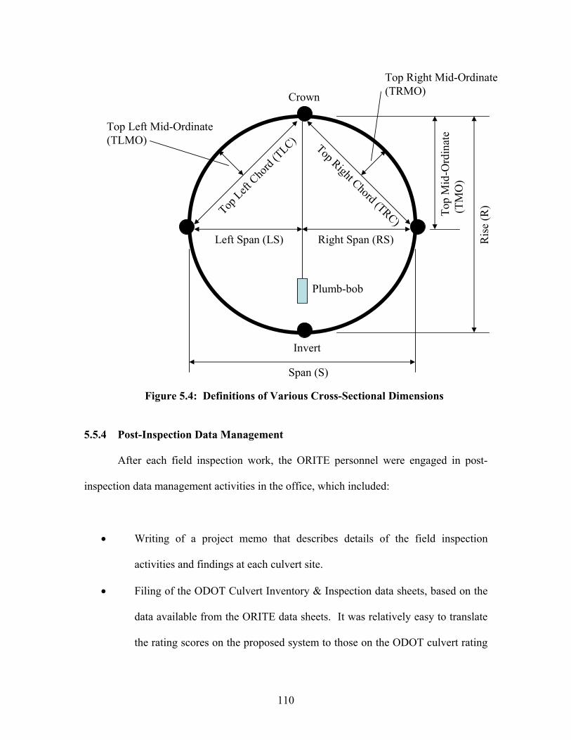
110
Crown
Invert
Span (S)
Ris
e (R
)Top
Mid
-Ord
inat
e(T
MO
)
Plumb-bob
Top Right Chord (TRC)Top
LeftCho
rd(T
LC)
Right Span (RS)Left Span (LS)
Top Right Mid-Ordinate(TRMO)
Top Left Mid-Ordinate(TLMO)
Figure 5.4: Definitions of Various Cross-Sectional Dimensions
5.5.4 Post-Inspection Data Management
After each field inspection work, the ORITE personnel were engaged in post-
inspection data management activities in the office, which included:
Writing of a project memo that describes details of the field inspection
activities and findings at each culvert site.
Filing of the ODOT Culvert Inventory & Inspection data sheets, based on the
data available from the ORITE data sheets. It was relatively easy to translate
the rating scores on the proposed system to those on the ODOT culvert rating

111
procedure, since they shared many common elements and also the proposed
system had somewhat higher resolutions.
Copying (to produce back-up duplicates) and filing of all the data sheets.
Entry of all the inspection data into computer database files.
Processing of all the digital camera pictures by saving them on a PC hard-
drive and a CD-ROM disc.
Analysis of the drainage water sample at the environmental laboratory.

112
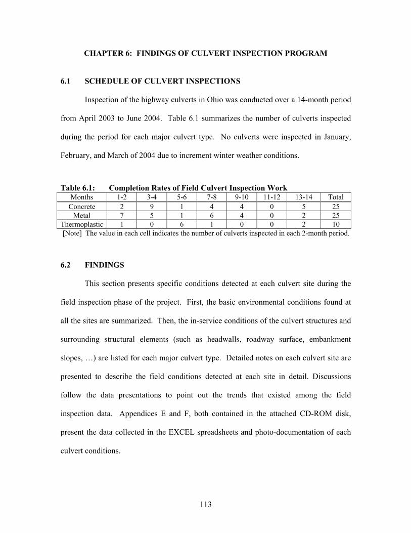
113
CHAPTER 6: FINDINGS OF CULVERT INSPECTION PROGRAM
6.1 SCHEDULE OF CULVERT INSPECTIONS
Inspection of the highway culverts in Ohio was conducted over a 14-month period
from April 2003 to June 2004. Table 6.1 summarizes the number of culverts inspected
during the period for each major culvert type. No culverts were inspected in January,
February, and March of 2004 due to increment winter weather conditions.
Table 6.1: Completion Rates of Field Culvert Inspection Work Months 1-2 3-4 5-6 7-8 9-10 11-12 13-14 Total
Concrete 2 9 1 4 4 0 5 25 Metal 7 5 1 6 4 0 2 25
Thermoplastic 1 0 6 1 0 0 2 10 [Note] The value in each cell indicates the number of culverts inspected in each 2-month period.
6.2 FINDINGS
This section presents specific conditions detected at each culvert site during the
field inspection phase of the project. First, the basic environmental conditions found at
all the sites are summarized. Then, the in-service conditions of the culvert structures and
surrounding structural elements (such as headwalls, roadway surface, embankment
slopes, …) are listed for each major culvert type. Detailed notes on each culvert site are
presented to describe the field conditions detected at each site in detail. Discussions
follow the data presentations to point out the trends that existed among the field
inspection data. Appendices E and F, both contained in the attached CD-ROM disk,
present the data collected in the EXCEL spreadsheets and photo-documentation of each
culvert conditions.
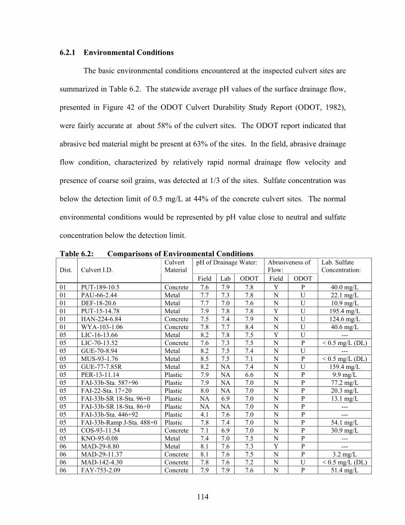
114
6.2.1 Environmental Conditions
The basic environmental conditions encountered at the inspected culvert sites are
summarized in Table 6.2. The statewide average pH values of the surface drainage flow,
presented in Figure 42 of the ODOT Culvert Durability Study Report (ODOT, 1982),
were fairly accurate at about 58% of the culvert sites. The ODOT report indicated that
abrasive bed material might be present at 63% of the sites. In the field, abrasive drainage
flow condition, characterized by relatively rapid normal drainage flow velocity and
presence of coarse soil grains, was detected at 1/3 of the sites. Sulfate concentration was
below the detection limit of 0.5 mg/L at 44% of the concrete culvert sites. The normal
environmental conditions would be represented by pH value close to neutral and sulfate
concentration below the detection limit.
Table 6.2: Comparisons of Environmental Conditions pH of Drainage Water: Abrasiveness of
Flow:Dist. Culvert I.D. Culvert Material
Field Lab ODOT Field ODOT
Lab. Sulfate Concentration:
01 PUT-189-10.5 Concrete 7.6 7.9 7.8 Y P 40.0 mg/L 01 PAU-66-2.44 Metal 7.7 7.3 7.8 N U 22.1 mg/L 01 DEF-18-20.6 Metal 7.7 7.0 7.6 N U 10.9 mg/L 01 PUT-15-14.78 Metal 7.9 7.8 7.8 Y U 195.4 mg/L 01 HAN-224-6.84 Concrete 7.5 7.4 7.9 N U 124.6 mg/L 01 WYA-103-1.06 Concrete 7.8 7.7 8.4 N U 40.6 mg/L 05 LIC-16-13.66 Metal 8.2 7.8 7.5 Y U --- 05 LIC-70-13.52 Concrete 7.6 7.3 7.5 N P < 0.5 mg/L (DL) 05 GUE-70-8.94 Metal 8.2 7.5 7.4 N U --- 05 MUS-93-1.76 Metal 8.5 7.5 7.1 N P < 0.5 mg/L (DL) 05 GUE-77-7.85R Metal 8.2 NA 7.4 N U 159.4 mg/L 05 PER-13-11.14 Plastic 7.9 NA 6.6 N P 9.9 mg/L 05 FAI-33b-Sta. 587+96 Plastic 7.9 NA 7.0 N P 77.2 mg/L 05 FAI-22-Sta. 17+20 Plastic 8.0 NA 7.0 N P 20.3 mg/L 05 FAI-33b-SR 18-Sta. 96+0 Plastic NA 6.9 7.0 N P 13.1 mg/L 05 FAI-33b-SR 18-Sta. 86+0 Plastic NA NA 7.0 N P --- 05 FAI-33b-Sta. 446+92 Plastic 4.1 7.6 7.0 N P --- 05 FAI-33b-Ramp J-Sta. 488+0 Plastic 7.8 7.4 7.0 N P 54.1 mg/L 05 COS-93-11.54 Concrete 7.1 6.9 7.0 N P 30.9 mg/L 05 KNO-95-0.08 Metal 7.4 7.0 7.5 N P --- 06 MAD-29-8.80 Metal 8.1 7.6 7.3 Y P --- 06 MAD-29-11.37 Concrete 8.1 7.6 7.5 N P 3.2 mg/L 06 MAD-142-4.30 Concrete 7.8 7.6 7.2 N U < 0.5 mg/L (DL) 06 FAY-753-2.09 Concrete 7.9 7.9 7.6 N P 51.4 mg/L
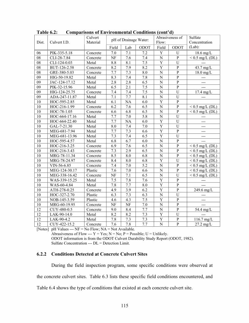
115
Table 6.2: Comparisons of Environmental Conditions (cont’d)
pH of Drainage Water: Abrasiveness of Flow:Dist. Culvert I.D.
Culvert Material
Field Lab ODOT Field ODOT
SulfateConcentration (Lab):
06 PIK-335-5.18 Concrete 7.0 7.1 7.2 Y U 18.6 mg/L 08 CLI-28-7.84 Concrete NF 7.6 7.4 N P < 0.5 mg/L (DL) 08 CLI-124-0.03 Metal 8.8 8.1 7.5 Y U --- 08 BUT-126-2.58 Concrete 8.2 7.9 8.2 Y P 43.7 mg/L 08 GRE-380-5.03 Concrete 7.7 7.3 8.0 N P 18.0 mg/L 09 HIG-50-19.82 Metal 8.3 7.4 7.8 N P --- 09 JAC-124-17.12 Metal 2.8 2.8 6.5 N P --- 09 PIK-32-15.96 Metal 6.5 2.1 7.5 N P --- 09 HIG-124-25.75 Concrete 7.4 7.4 7.5 N U 17.4 mg/L 09 ADA-247-11.87 Metal 7.1 7.7 8.1 N U --- 10 HOC-595-2.85 Metal 6.1 NA 6.0 Y P 10 HOC-216-1.99 Concrete 6.2 7.6 6.5 N P < 0.5 mg/L (DL) 10 HOC-78-1.05 Concrete 6.6 6.8 6.5 N P < 0.5 mg/L (DL) 10 HOC-664-17.16 Metal 7.7 7.0 5.8 N U --- 10 HOC-664-22.40 Metal 7.7 NA 6.0 Y U --- 10 GAL-7-21.30 Metal 8.0 7.4 7.0 Y U --- 10 MEG-681-7.94 Metal 7.7 7.3 6.6 Y P --- 10 MEG-681-13.96 Metal 7.3 7.4 6.5 Y U --- 10 HOC-595-4.57 Metal 6.8 6.7 6.0 N P --- 10 HOC-216-3.25 Concrete 6.9 7.6 6.5 N P < 0.5 mg/L (DL) 10 HOC-216-3.43 Concrete 7.3 2.9 6.5 N P < 0.5 mg/L (DL) 10 MRG-78-11.34 Concrete 8.5 8.0 6.8 N P < 0.5 mg/L (DL) 10 MRG-78-24.97 Concrete 8.4 8.0 6.8 Y U < 0.5 mg/L (DL) 10 VIN-56-6.85 Concrete 7.4 7.0 5.2 N P < 0.5 mg/L (DL) 10 MEG-124-30.17 Plastic 7.6 7.0 6.6 N P < 0.5 mg/L (DL) 10 MEG-338-16.42 Concrete NF 7.1 6.5 N U < 0.5 mg/L (DL) 10 WAS-339-15.25 Metal 7.5 7.8 7.6 Y P --- 10 WAS-60-4.84 Metal 7.8 7.7 8.0 Y P --- 10 ATH-278-0.25 Concrete 4.9 3.9 6.2 Y P 249.6 mg/L 10 HOC-327-2.70 Plastic 6.3 7.3 6.3 N U --- 10 NOB-145-3.59 Plastic 4.6 4.3 7.5 Y P --- 10 MRG-60-19.95 Concrete NF NF 7.0 N P --- 12 CUY-480-0.5 Concrete 9.0 8.4 7.7 N P 54.4 mg/L 12 LAK-90-14.0 Metal 8.2 8.2 7.3 Y U --- 12 LAK-90-4.2 Metal 7.8 7.3 7.3 Y P 116.7 mg/L 12 CUY-422-15.2 Concrete 7.6 7.8 7.7 N P 27.2 mg/L [Notes] pH Values --- NF = No Flow; NA = Not Available. Abrasiveness of Flow --- Y = Yes; N = No; P = Possible; U = Unlikely. ODOT information is from the ODOT Culvert Durability Study Report (ODOT, 1982).
Sulfate Concentration --- DL = Detection Limit.
6.2.2 Conditions Detected at Concrete Culvert Sites
During the field inspection program, some specific conditions were observed at
the concrete culvert sites. Table 6.3 lists these specific field conditions encountered, and
Table 6.4 shows the type of conditions that existed at each concrete culvert site.
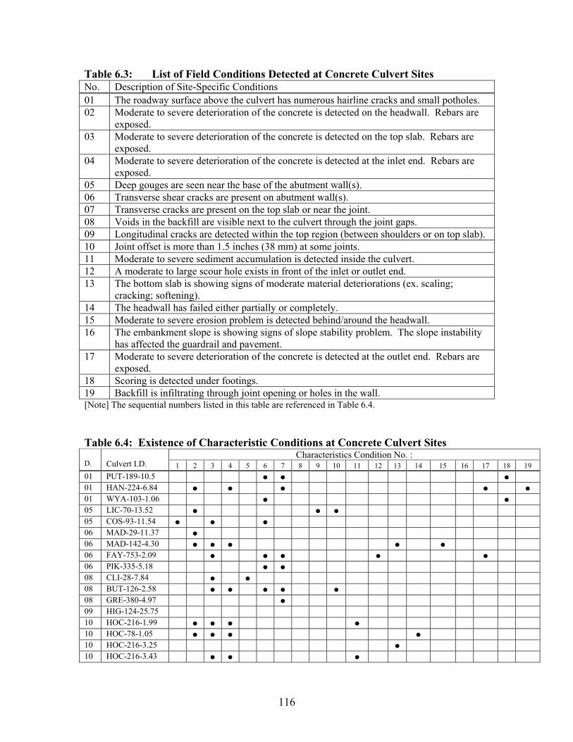
116
Table 6.3: List of Field Conditions Detected at Concrete Culvert Sites No. Description of Site-Specific Conditions 01 The roadway surface above the culvert has numerous hairline cracks and small potholes. 02 Moderate to severe deterioration of the concrete is detected on the headwall. Rebars are
exposed.03 Moderate to severe deterioration of the concrete is detected on the top slab. Rebars are
exposed.04 Moderate to severe deterioration of the concrete is detected at the inlet end. Rebars are
exposed.05 Deep gouges are seen near the base of the abutment wall(s). 06 Transverse shear cracks are present on abutment wall(s). 07 Transverse cracks are present on the top slab or near the joint. 08 Voids in the backfill are visible next to the culvert through the joint gaps. 09 Longitudinal cracks are detected within the top region (between shoulders or on top slab). 10 Joint offset is more than 1.5 inches (38 mm) at some joints. 11 Moderate to severe sediment accumulation is detected inside the culvert. 12 A moderate to large scour hole exists in front of the inlet or outlet end. 13 The bottom slab is showing signs of moderate material deteriorations (ex. scaling;
cracking; softening). 14 The headwall has failed either partially or completely. 15 Moderate to severe erosion problem is detected behind/around the headwall. 16 The embankment slope is showing signs of slope stability problem. The slope instability
has affected the guardrail and pavement. 17 Moderate to severe deterioration of the concrete is detected at the outlet end. Rebars are
exposed.18 Scoring is detected under footings. 19 Backfill is infiltrating through joint opening or holes in the wall. [Note] The sequential numbers listed in this table are referenced in Table 6.4.
Table 6.4: Existence of Characteristic Conditions at Concrete Culvert Sites Characteristics Condition No. :
D. Culvert I.D. 1 2 3 4 5 6 7 8 9 10 11 12 13 14 15 16 17 18 1901 PUT-189-10.5 01 HAN-224-6.84 01 WYA-103-1.06 05 LIC-70-13.52 05 COS-93-11.54 06 MAD-29-11.37 06 MAD-142-4.30 06 FAY-753-2.09 06 PIK-335-5.18 08 CLI-28-7.84 08 BUT-126-2.58 08 GRE-380-4.97 09 HIG-124-25.75 10 HOC-216-1.99 10 HOC-78-1.05 10 HOC-216-3.25 10 HOC-216-3.43
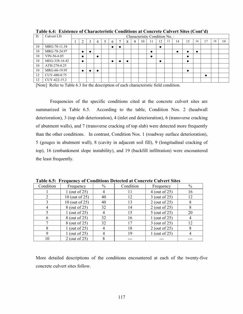
117
Table 6.4: Existence of Characteristic Conditions at Concrete Culvert Sites (Cont’d) Characteristic Condition No. : D. Culvert I.D.
1 2 3 4 5 6 7 8 9 10 11 12 13 14 15 16 17 18 1910 MRG-78-11.34 10 MRG-78-24.97 10 VIN-56-6.85 10 MEG-338-16.42 10 ATH-278-0.25 10 MRG-60-19.95 12 CUY-480-0.75 12 CUY-422-15.2 [Note] Refer to Table 6.3 for the description of each characteristic field condition.
Frequencies of the specific conditions cited at the concrete culvert sites are
summarized in Table 6.5. According to the table, Condition Nos. 2 (headwall
deterioration), 3 (top slab deterioration), 4 (inlet end deterioration), 6 (transverse cracking
of abutment walls), and 7 (transverse cracking of top slab) were detected more frequently
than the other conditions. In contrast, Condition Nos. 1 (roadway surface deterioration),
5 (gouges in abutment wall), 8 (cavity in adjacent soil fill), 9 (longitudinal cracking of
top), 16 (embankment slope instability), and 19 (backfill infiltration) were encountered
the least frequently.
Table 6.5: Frequency of Conditions Detected at Concrete Culvert Sites Condition Frequency % Condition Frequency %
1 1 (out of 25) 4 11 4 (out of 25) 16 2 10 (out of 25) 40 12 3 (out of 25) 12 3 10 (out of 25) 40 13 2 (out of 25) 8 4 8 (out of 25) 32 14 2 (out of 25) 8 5 1 (out of 25) 4 15 5 (out of 25) 20 6 8 (out of 25) 32 16 1 (out of 25) 4 7 8 (out of 25) 32 17 3 (out of 25) 12 8 1 (out of 25) 4 18 2 (out of 25) 8 9 1 (out of 25) 4 19 1 (out of 25) 4
10 2 (out of 25) 8 --- --- ---
More detailed descriptions of the conditions encountered at each of the twenty-five
concrete culvert sites follow.
118
The culvert PUT-189-10.5 (9’ or 2.7 m-span cast-in-place concrete slab-on-top)
was scheduled for replacement in 2006. This culvert was extended 6 to 7 ft (1.83 to 2.13
m) in each direction. The extension was done in such a way that the culvert became
aligned like the letter S. Because of the non-straight horizontal alignment, the drainage
flow hit the east abutment wall upon entering the culvert. The headwall at each end had
several hairline cracks and signs of moderate spalling. The top slab appeared newer than
the abutment walls in the original section in the middle. However, the slab had
transverse cracks in the inlet and outlet sections. Also, additional hairline cracks were
visible on the top slab under the roadway centerline. The original abutment walls had
some major cracks. The east abutment wall had three cracks running either vertically or
diagonally over its entire height. Also, it had a horizontal crack right above the
wall/footing joint. The west abutment had two vertical and one horizontal cracks. The
footing under the east abutment appeared to be scoured due to the impact from the
entering drainage flow. The roadway surface appeared relatively new and free of any
defects.
The culvert HAN-224-6.84 (6’ or 1.83 m diameter RCP) consisted of twenty-five
sections of RCP joined together. The inlet end (Section #25) had several cracks mostly in
the haunch region. On the bell end, concrete was chipped off from the 3:00 to 6:00
o’clock positions, with the rebars exposed. The outlet end (Section #1) had conditions
similar to those found on the inlet end. Transverse cracks were occasionally detected
near the joint. There were also numerous spots where the thin layer of concrete
delaminated over the rebars through scaling. The pipe sections which had more of this

119
problem were Sections #1, #9, #14, and #17. No longitudinal cracks were detected in the
crown region. Backfill was infiltrating into the culvert through a 4-inch (102-mm)
opening at the joint between Section #22 and Section #23 (shown in Figure 6.1). The
headwall at each end was showing signs of advanced stage of material deterioration
(numerous cracks; softening) due to a combination of impacts from moving debris and
chloride attack, as seen in Figure 6.2.
Figure 6.1: Backfill Infiltrating Through Joint Opening (HAN-224-6.84)
Figure 6.2: Deteriorated Headwall at Inlet of HAN-224-6.84
120
Abutment walls inside the culvert WYA-103-1.06 (5’ or 1.52 m-span cast-in-
place concrete slab-on-top) were not vertical and both tilted toward the backfill. The
lower section of the walls was showing signs of moderate spalling. Each wall also had a
major horizontal crack running along the culvert length as well as some diagonal cracks.
There was a minor scoring underneath the footing of the north abutment wall. The top
slab appeared relatively new and had very few hairline cracks under the traffic lanes. The
edges of the top slab at the inlet and outlet ends were cracked and soft. At the inlet, the
channel made a 90˚ turn, with the flow hitting the extension of the north abutment wall.
The roadway surface looked relatively new and free of any defects.
The culvert LIC-70-13.52 (6’ or 1.83 m diameter RCP) consisted of fifty-eight
sections joined together. At this site, longitudinal hairline cracks were detected within
the top section between Section #5 to Section #54 (see Figure 6.3). None of the cracks
had iron staining. At some locations, the cracks developed a map pattern, causing small
scaling in the area. Section #33 had a 1/8-inch (3-mm) width crack running along its
length at the shoulder. The joint offset was as much as 1.5 inches (38 mm) at the joints
between Section #11 and Section #12 and joint between Section #32 and Section #33.
No signs of backfill infiltration were found anywhere between the ends. The culvert
appeared to have a minor sagging in the middle. At each end, one side of the headwall
had more cracks and material deteriorations. Only a minor (5 inches or 127 mm deep)
scour was detected at the inlet end.

121
Figure 6.3: Longitudinal Crack Detected at Crown of LIC-70-13.52
The culvert COS-93-11.54 (7’ x 5’ or 2.13 m x 1.52 m cast-in-place concrete box)
served more as a flood control. No drainage flow was flowing through the culvert during
the inspection. Two notable conditions existed inside the culvert. First, transverse cracks
as wide as 1 inch (25 mm) were detected on each abutment wall at four locations.
Granular backfill soil was infiltrating into the culvert through the cracks. Secondly, the
top slab had two regions where a 2 to 3 inch (51 to 76 mm) thick layer of concrete
delaminated exposing the first layer of rebars. The pavement surface above the culvert
had numerous hairline cracks and small potholes.
The culvert structure MAD-29-11.37 (4’ x 4’ or 1.22 m x 1.22 m cast-in-place
concrete box) served more as a flood control. No drainage flow was flowing through the
culvert during the inspection. Deteriorated material conditions, mainly due to salt
applications in the winter time, were observed on the headwalls, the wingwalls, and the
top slab. However, no exposed rebars were detected in any of the regions.
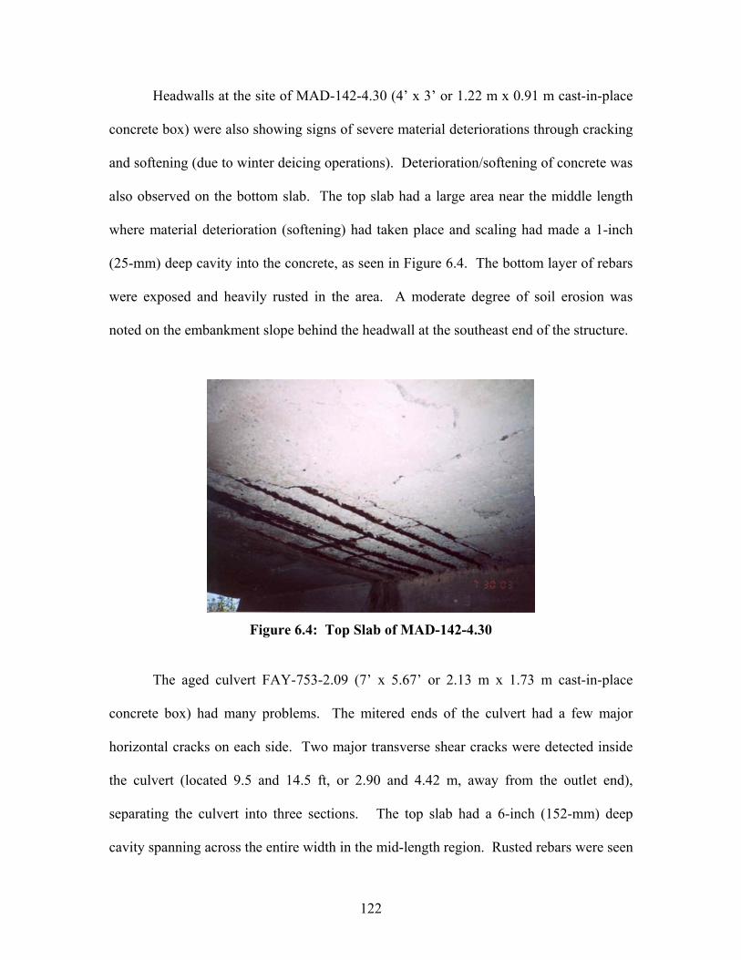
122
Headwalls at the site of MAD-142-4.30 (4’ x 3’ or 1.22 m x 0.91 m cast-in-place
concrete box) were also showing signs of severe material deteriorations through cracking
and softening (due to winter deicing operations). Deterioration/softening of concrete was
also observed on the bottom slab. The top slab had a large area near the middle length
where material deterioration (softening) had taken place and scaling had made a 1-inch
(25-mm) deep cavity into the concrete, as seen in Figure 6.4. The bottom layer of rebars
were exposed and heavily rusted in the area. A moderate degree of soil erosion was
noted on the embankment slope behind the headwall at the southeast end of the structure.
Figure 6.4: Top Slab of MAD-142-4.30
The aged culvert FAY-753-2.09 (7’ x 5.67’ or 2.13 m x 1.73 m cast-in-place
concrete box) had many problems. The mitered ends of the culvert had a few major
horizontal cracks on each side. Two major transverse shear cracks were detected inside
the culvert (located 9.5 and 14.5 ft, or 2.90 and 4.42 m, away from the outlet end),
separating the culvert into three sections. The top slab had a 6-inch (152-mm) deep
cavity spanning across the entire width in the mid-length region. Rusted rebars were seen

123
inside the depression. The top slab had a 12-inch (305-mm) length section missing over
the entire width at the outlet end. Despite all the cracks, no signs of backfill infiltration
were seen inside the culvert. The bottom slab concrete was showing moderate degree of
spalling. A 5-inch (127-mm) scour was found in front of the inlet end. At the outlet end,
the stream bed was 28 inches (711 mm) lower than the culvert bottom slab surface. No
concrete headwalls existed at the site. Instead, flag stones were stacked up next to the
culvert end.
The culvert PIK-335-5.18 (14’ x 6.67’ or 4.27 m x 2.03 m cast-in-place concrete
slab-on-top) had a slightly arched top slab and consisted of three sections joined together.
Iron-stained transverse cracks were detected near each joint, delaminating the concrete to
the first layer of rebars. Minor seepage infiltration was observed at both construction
joints.
At the site of CLI-28-7.84 (8’ or 2.44 m span cast-in-place concrete slab-on-top),
several mid-size areas of concrete deteriorations (3 to 4-inch, or 76 to 102 mm, deep
scaled cavity, rusted rebars exposed) were detected on the top slab. Gouges at least 6 to
10 inches (152 to 254 mm) deep existed in the lower portion, just above the flow line
level, of the abutment wall (see Figure 6.5). There was one transverse crack across the
entire pavement width, located 3 to 4 ft (0.91 to 1.22 m) away from the western edge of
the culvert.

124
The culvert BUT-126-2.58 (8’ or 2.44 m-span cast-in-place concrete slab-on-top)
had three distinct sections tied in together. The inlet and outlet ends were both cast in-
place concrete structures. The main barrel was an older section where the abutment walls
were constructed of mortared stones. Concrete was cracked and soft (with rebars
exposed) at the edge of the top slab at the inlet end. Mild degree of spalling was seen in
the lower area of the headwalls. Each joint between the concrete section and the older
masonry section was cracked (crack width 1/10 to 1/4” or 3 to 6 mm).
Figure 6.5: Deteriorated Lower Section of Abutment Wall (CLI-28-7.84)
Horizontal cracks were observed running through the wall just above the normal
flow line. There was a 2.5-inch (64-mm) differential settlement between them near the
inlet and 1-inch (25-mm) differential settlement near the outlet. Obviously, the main
barrel section had settled more than the end sections. The stone walls in the main barrel
were not vertical. On each wall, the mortar had been totally lost between the stones at
several locations. This created a deep hole as large as 1 inch (25 mm) in diameter at each
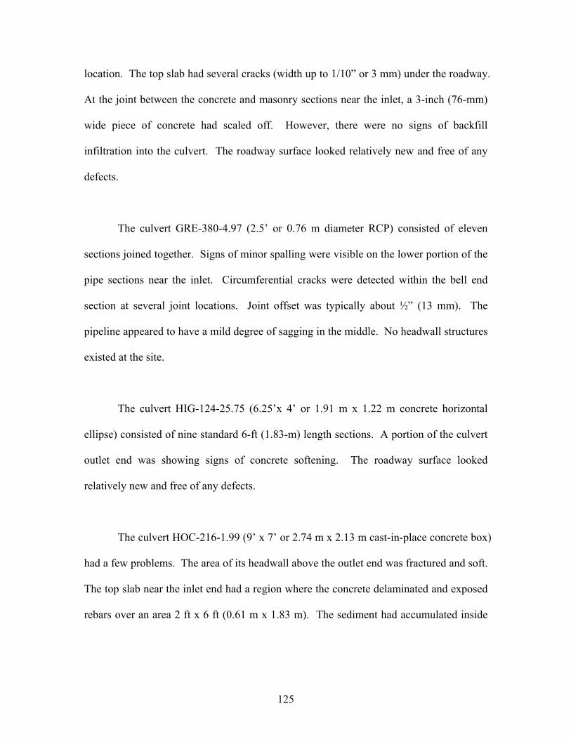
125
location. The top slab had several cracks (width up to 1/10” or 3 mm) under the roadway.
At the joint between the concrete and masonry sections near the inlet, a 3-inch (76-mm)
wide piece of concrete had scaled off. However, there were no signs of backfill
infiltration into the culvert. The roadway surface looked relatively new and free of any
defects.
The culvert GRE-380-4.97 (2.5’ or 0.76 m diameter RCP) consisted of eleven
sections joined together. Signs of minor spalling were visible on the lower portion of the
pipe sections near the inlet. Circumferential cracks were detected within the bell end
section at several joint locations. Joint offset was typically about ½” (13 mm). The
pipeline appeared to have a mild degree of sagging in the middle. No headwall structures
existed at the site.
The culvert HIG-124-25.75 (6.25’x 4’ or 1.91 m x 1.22 m concrete horizontal
ellipse) consisted of nine standard 6-ft (1.83-m) length sections. A portion of the culvert
outlet end was showing signs of concrete softening. The roadway surface looked
relatively new and free of any defects.
The culvert HOC-216-1.99 (9’ x 7’ or 2.74 m x 2.13 m cast-in-place concrete box)
had a few problems. The area of its headwall above the outlet end was fractured and soft.
The top slab near the inlet end had a region where the concrete delaminated and exposed
rebars over an area 2 ft x 6 ft (0.61 m x 1.83 m). The sediment had accumulated inside
126
the culvert, limiting the head space to only about 4 ft (1.22 m) and the surface drainage
flows only on one side.
The headwalls of HOC-78-1.05 (6’ x 4’ or 1.83 m x 1.22 m cast-in-place concrete
box) had deteriorated so severely that more than a half of the initial headwall was missing
and three rows of rebars were suspending in the air (see Figure 6.6). Inside the culvert, a
few shear cracks were visible on the side walls. And, the bottom slab had a moderate
degree of spalling affecting its surface.
Some longitudinal hairline cracks were observed on the top slab in the inlet
section of HOC-216-3.25 (4’ x 3’ or 1.22 m x 0.91 m cast-in-place concrete box). There
were a few locations on the top slab where the concrete scaled over a small area. The
bottom slab was affected by moderate degree of spalling. The roadway surface was free
of any defects.
Figure 6.6: Deteriorated Headwall at Inlet of HOC-78-1.05
127
A comprehensive culvert inspection was not possible at the site of HOC-216-3.43
(5’ x 3’ or 1.52 m x 0.91 m cast-in-place concrete box), because the sediment
accumulation left only the top 1.5-ft (0.46-m) section of the culvert visible. The top slab
at the outlet end was showing signs of severe material deterioration (numerous cracking,
softening). Rebars were exposed, and the concrete broke off in pieces easily when
stricken by a pick. No headwalls and guardrails existed at the site.
At the site of MRG-78-11.34 (8’ x 6’ or 2.44 m x 1.83 m cast-in-place concrete
box), a 10-inch (0.25-m) deep scour hole was present in front of the inlet end. Inside this
culvert, transverse shear cracks were detected running through the abutment walls and the
top slab at two locations. Locations of these transverse cracks appeared to define the
width of the traffic lanes. Along the crack, shallow scaling problems existed at isolated
located. No guardrails were seen at this site.
No direct entry inspection of the culvert was possible at the site of MRG-78-24.97
(2.5’ x 2.5’ or 0.76 m x 0.76 m cast-in-place concrete box), due to its small size and the
fact that a 4.5-inch (114-mm) diameter natural gas pipeline, elevated 12 inches (0.31 m)
above the bottom slab, was running through the culvert. Many large boulders were seen
lodged underneath the pipeline inside the culvert. The top slab had numerous cracks and
moderate to severe material deteriorations. At some isolated locations, the top slab
concrete developed ½-inch (13-mm) deep scaled hole, exposing rusted rebars. The
headwall/wingwall at the outlet end was in an advanced stage of material deterioration.
The concrete was heavily cracked, very soft, exposing internal rebars, and missing a large
128
portion. There was a 2.5-ft (0.76-m) drop from the culvert invert to the stream bed at the
outlet end. The embankment slope on the outlet side was steep and showing signs of
local slope stability problem.
The culvert VIN-56-6.85 (8’ x 6’ or 2.44 m x 1.83 m cast-in-place concrete box)
was silted up to the point that only the upper 3.5-ft (1.07-m) section was accessible to
inspection. The inlet section of the culvert had moderate spalling and scaling on the top
slab, exposing the first layer of rebars at one isolated location. The headwall/wingwall
assembly showed signs of material deterioration at both ends. At the inlet end, the joint
between the wall and the culvert end was open and exposing steel angle placed inside.
Also, there was a piece of concrete missing on the west side. At the outlet end, the
concrete in the headboard was cracked extensively, soft, and exposing rusted rebars all
across its width. Moderate degree of erosion was taking place behind the wingwall on
one side at the inlet end.
The culvert MEG-338-16.42 (4’ x 4’ or 1.22 m x 1.22 m cast-in-place concrete
box) broke into four sections by developing transverse shear cracks at 23.5 ft (7.16 m)
(1st location) away from the inlet end, 42 ft (12.80 m) (2nd location) away from the inlet
end, and 10 ft (3.05 m) away (3rd location) from outlet end. The crack width was up to 2
inches (51 mm) at the first location, up to 3 inches (76 mm) at the second location, and up
to ½ inches (13 mm) at the third location. At the first location, seepage infiltration was
noted. At the second location, a void space, extending 13 inches (0.33 m) into the
adjacent soil fill, was visible through the 3-inch (76-mm) wide crack. At the third
129
sheared location, a 1.5-inch (38-mm) differential settlement was measured between the
two sides of the crack. Moderate to severe erosion was detected behind the wingwalls.
The stream bed dropped off 12 inches (0.31 m) at the inlet end and more than 3 ft (0.91 m)
at the outlet end.
An aged metal culvert was listed for location ATH-278-0.25. Instead, a 7.5’ x
4.83’ or 2.29 m x 1.47 m concrete horizontal ellipse culvert was found at the site.
According to ODOT, the culvert was installed in 2002, while repaving the roadway. This
culvert consisted of eight sections joined together. Joint offset was typically ¾ to 1
inches (19 to 25 mm).
The culvert MRG-60-19.95 (4’ x 6’ or 1.22 m x 1.83 m cast-in-place concrete box)
was installed to handle drainage from the hill side during rainfall events. So, it normally
had no water flowing through it during dry periods. The culvert had an 11-ft (3.35-m)
long extension on the outlet side. The edge of the top slab at the inlet had deteriorated to
the point that it had nothing but rusted rebars. The upper half of the headwall was also
showing signs of severe material deterioration. The concrete wall surface was rough with
numerous hairline cracks and very soft. Inside the culvert, the top slab had some hairline
cracks and minor scaling but was still solid. The lower part of the abutment walls and the
bottom slab surface had moderate spalling with its surface rough and aggregates being
exposed. At the joint between the original section and extension section, there were a
few small areas on the top slab where the concrete had scaled and the rebars were
130
exposed. The area behind the headwall at the outlet end had moderate erosion problem.
Above the inlet end, the edge of the asphalt pavement layer was cracked and falling.
The culvert CUY-480-0.75 (7’ or 2.13 m diameter RCP) showed signs of minor
spalling near the flow line elevation throughout its length. Hairline cracks were
occasionally seen running either circumferentially or diagonally in the crown region.
There were some medium sized (1’ x 1’ to 2’ x 3’ or 0.3 m x 0.3 m to 0.6 m x 0.6 m)
areas where the thin layer of concrete delaminated over the rebars through scaling. At
two locations, small diameter corrugated metal drain pipes connected to the culvert in the
shoulder region. Concrete had become fractured and soft at each of these junctions. At
the outlet end, the invert had 80% of the concrete gone and all the rebars exposed due to
severe material deteriorations.
The culvert CUY-422-15.2 (4’ or 1.22 m diameter RCP) appeared to be a
relatively new installation. The concrete surface had no hairline cracks and showed little
material deterioration. The pipeline consisted of twenty-two standard 8-ft (2.44-m)
length sections joined together. The roadway surface looked relatively new and free of
any defects.
6.2.3 Conditions Detected at Metal Culvert Sites
During the field inspection program, some specific conditions were observed at
the metal culvert sites. Table 6.6 lists these specific fiend conditions encountered, and
Table 6.7 shows the type of conditions that existed at each metal culvert site. By far the
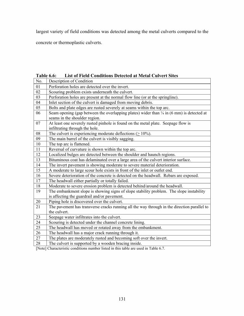
131
largest variety of field conditions was detected among the metal culverts compared to the
concrete or thermoplastic culverts.
Table 6.6: List of Field Conditions Detected at Metal Culvert Sites No. Description of Condition 01 Perforation holes are detected over the invert. 02 Scouring problem exists underneath the culvert. 03 Perforation holes are present at the normal flow line (or at the springline). 04 Inlet section of the culvert is damaged from moving debris. 05 Bolts and plate edges are rusted severely at seams within the top arc. 06 Seam opening (gap between the overlapping plates) wider than ¼ in (6 mm) is detected at
seams in the shoulder region. 07 At least one severely rusted pinhole is found on the metal plate. Seepage flow is
infiltrating through the hole. 08 The culvert is experiencing moderate deflections (> 10%). 09 The main barrel of the culvert is visibly sagging. 10 The top arc is flattened. 11 Reversal of curvature is shown within the top arc. 12 Localized bulges are detected between the shoulder and haunch regions. 13 Bituminous coat has delaminated over a large area of the culvert interior surface. 14 The invert pavement is showing moderate to severe material deterioration. 15 A moderate to large scour hole exists in front of the inlet or outlet end. 16 Severe deterioration of the concrete is detected on the headwall. Rebars are exposed. 17 The headwall either partially or totally failed. 18 Moderate to severe erosion problem is detected behind/around the headwall. 19 The embankment slope is showing signs of slope stability problem. The slope instability
is affecting the guardrail and/or pavement. 20 Piping hole is discovered over the culvert. 21 The pavement has transverse cracks running all the way through in the direction parallel to
the culvert. 23 Seepage water infiltrates into the culvert. 24 Scouring is detected under the channel concrete lining. 25 The headwall has moved or rotated away from the embankment. 26 The headwall has a major crack running through it. 27 The plates are moderately rusted and becoming soft over the invert. 28 The culvert is supported by a wooden bracing inside. [Note] Characteristic conditions number listed in this table are used in Table 6.7.

132
Table 6.7: Existence of Characteristic Conditions at Metal Culvert Sites Characteristic Condition No.:
Dist. Culvert I.D. 1 2 3 4 5 6 7 8 9 10 11 12 13 1401 PAU-66-2.44 01 DEF-18-20.60 01 PUT-15-14.78 05 LIC-16-13.66 05 GUE-70-8.94 05 MUS-93-1.76 05 GUE-77-7.85R 05 KNO-95-0.08 06 MAD-29-8.80 08 CLI-124-0.03 09 HIG-50-19.82 09 JAC-124-17.12 09 PIK-32-15.96 09 ADA-247-11.87 10 HOC-595-2.85 10 HOC-664-17.16 10 HOC-664-22.40 10 GAL-7-21.30 10 MEG-681-7.94 10 MEG-681-13.96 10 HOC-595-4.57 10 WAS-339-15.25 10 WAS-60-4.84 12 LAK-90-14.00 12 LAK-90-4.20 [Note] See Table 6.6 for descriptions of each characteristic condition.
Table 6.7: Existence of Characteristic Conditions at Metal Culvert Sites (cont’d) Characteristic Condition No.:
Dist. Culvert I.D. 15 16 17 18 19 20 21 22 23 24 25 26 27 2801 PAU-66-2.44 01 DEF-18-20.60 01 PUT-15-14.78 05 LIC-16-13.66 05 GUE-70-8.94 05 MUS-93-1.76 05 GUE-77-7.85R 05 KNO-95-0.08 06 MAD-29-8.80 08 CLI-124-0.03 09 HIG-50-19.82 09 JAC-124-17.12 09 PIK-32-15.96 09 ADA-247-11.87 10 HOC-595-2.85 10 HOC-664-17.16 10 HOC-664-22.40 [Note] See Table 6.6 for descriptions of each characteristic condition.
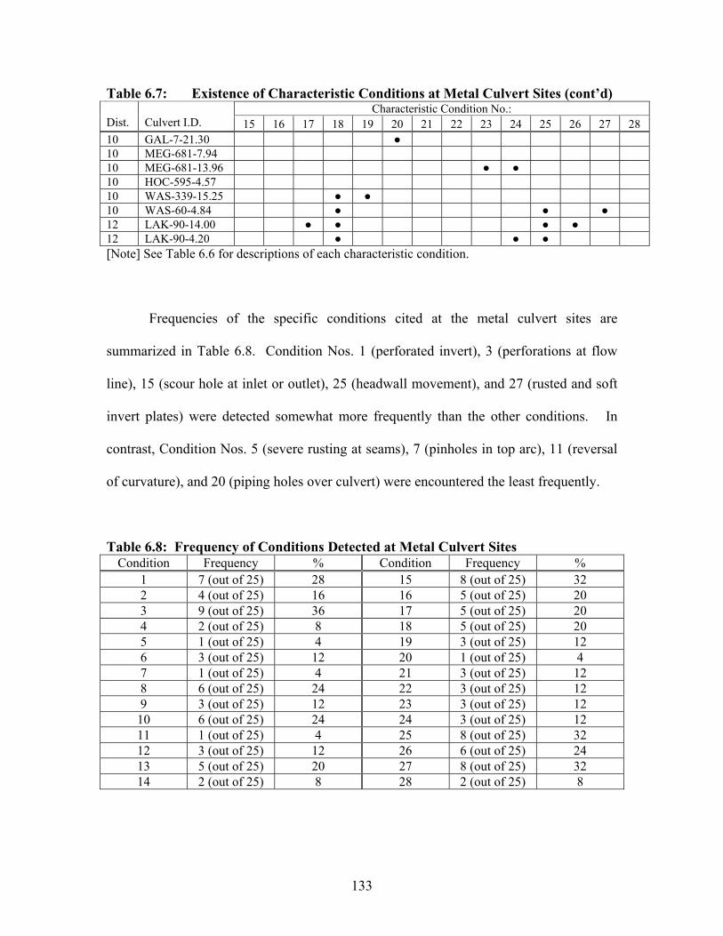
133
Table 6.7: Existence of Characteristic Conditions at Metal Culvert Sites (cont’d) Characteristic Condition No.:
Dist. Culvert I.D. 15 16 17 18 19 20 21 22 23 24 25 26 27 2810 GAL-7-21.30 10 MEG-681-7.94 10 MEG-681-13.96 10 HOC-595-4.57 10 WAS-339-15.25 10 WAS-60-4.84 12 LAK-90-14.00 12 LAK-90-4.20 [Note] See Table 6.6 for descriptions of each characteristic condition.
Frequencies of the specific conditions cited at the metal culvert sites are
summarized in Table 6.8. Condition Nos. 1 (perforated invert), 3 (perforations at flow
line), 15 (scour hole at inlet or outlet), 25 (headwall movement), and 27 (rusted and soft
invert plates) were detected somewhat more frequently than the other conditions. In
contrast, Condition Nos. 5 (severe rusting at seams), 7 (pinholes in top arc), 11 (reversal
of curvature), and 20 (piping holes over culvert) were encountered the least frequently.
Table 6.8: Frequency of Conditions Detected at Metal Culvert Sites Condition Frequency % Condition Frequency %
1 7 (out of 25) 28 15 8 (out of 25) 32 2 4 (out of 25) 16 16 5 (out of 25) 20 3 9 (out of 25) 36 17 5 (out of 25) 20 4 2 (out of 25) 8 18 5 (out of 25) 20 5 1 (out of 25) 4 19 3 (out of 25) 12 6 3 (out of 25) 12 20 1 (out of 25) 4 7 1 (out of 25) 4 21 3 (out of 25) 12 8 6 (out of 25) 24 22 3 (out of 25) 12 9 3 (out of 25) 12 23 3 (out of 25) 12
10 6 (out of 25) 24 24 3 (out of 25) 12 11 1 (out of 25) 4 25 8 (out of 25) 32 12 3 (out of 25) 12 26 6 (out of 25) 24 13 5 (out of 25) 20 27 8 (out of 25) 32 14 2 (out of 25) 8 28 2 (out of 25) 8

134
The followings are more detailed descriptions of the conditions encountered at
each of the twenty-five metal culvert sites.
The twin pipes PAU-66-2.44 (4.5’ or 1.37 m diameter twin metal pipes) are
scheduled to be replaced in 2006. The pipes were both 64.8 ft (19.8 m) in length and
consisted of bolted corrugated plates of size 2.75” (70 mm) pitch x 0.5” (13 mm) depth
(thickness 0.116” or 3 mm). The pipes had bituminous coating applied fully inside.
Initial walk-through of the two pipes indicated very similar conditions inside the two
pipes. The bituminous coat was still intact in the crown region. The coat had been
largely removed below the shoulders. Rusting of the steel plates was light above the
springline and moderate below the springline. The inlet and outlet sections had at least a
few small perforation holes scattered near the normal flow line level. No perforation
holes were detected within the main barrel section. Inside diameter measurements taken
at a few different stations showed that maximum vertical deflection of 8% existed at the
mid-length. The pipes had a slight sag in the middle. A sign of water infiltration was
observed at a few seams. There were concrete headwalls constructed at the ends. Instead,
at each end the embankment slope enveloping the two pipe ends was concreted. The
concrete slope protection looked good on the inlet side. The one at the outlet had a few
major cracks. The roadway surface looked relatively new and free of any major defects.
There were no guardrails at this site.
The culvert DEF-18-20.6 (6’ x 3.67’ or 1.83 m x 1.12 m metal pipe-arch)
consisted of 2.75” (70 mm) pitch by 0.5” (13 mm) depth corrugated plates (thickness
135
0.159” or 4 mm) bolted together. This culvert is also scheduled for replacement in 2005.
It appeared that initially the plates had been covered with bituminous coat. The
bituminous coat was still intact in the crown region. The coat had been largely removed
below the shoulders. The plates had moderate degree of rusting especially below the
shoulder area. No perforation holes were visible within the top arc and sides. The invert
was under a thick silty sediment deposit and could not be inspected. The culvert
appeared to have a mild sag in the middle. Tape measurements taken inside the culvert
indicated that the vertical deflection might be between 10-14%. There were no concrete
headwalls installed at the ends. The culvert ends were metered to conform to the
embankment slope.
The culvert PUT-15-14.78 (8’ or 2.44 m diameter metal pipe) consisted of 6”
(152 mm) pitch by 2” (51 mm) depth corrugated plates (thickness 0.139” or 4 mm) bolted
together at seams. No protective coating had been applied to the plate surfaces.
Measurements taken inside the culvert detected only small (less than 2-3%) deflections.
Metal plates in the top arc had occasional light corrosion. There were many medium size
(2” x 3” or 51 mm x 76 mm) perforation holes on the corrugation crests just below the
normal flow line. The headwall at the inlet had numerous hairline cracks, missing a
small portion on the left side. The headwall at the outlet had a major horizontal crack as
well as numerous hairline cracks. It appeared that the upper half of the wall had moved
away from the embankment. At the outlet, the stream bed was 7 ft (2.13 m) lower than
the pipe invert. The pavement was resurfaced recently and looked very good. This
culvert is scheduled for replacement in 2005.

136
The culvert LIC-16-13.66 (6.3’ or 1.92 m diameter metal pipe) had 3 to 4-inch
(76 to 102-mm) diameter perforation holes in the right haunch area, close to the air/water
interface, at isolated locations. It was not possible to inspect the invert section because of
sediment accumulation. At 33 ft (10.1 m) away from the outlet, seepage water was
squirting out through a couple of pinholes located at the right haunch (as shown in Figure
6.7). The top arc was relatively flat over the length of the culvert positioned under the
maximum fill height. No stress cracks were detected at bolt lines. Moderate rusting of
plates and bolts was observed along seams near the outlet end. The stream bed was
significantly lower than the culvert invert at the outlet. The headwall at the inlet was
showing damage received from moving debris on the front side and erosion taking place
behind. The headwall at the outlet looked rotated. Also, the concrete face below the
invert exhibited spalling/flaking.
Figure 6.7: Seepage Water Flowing In Through Pinhole (LIC-16-13.66)

137
The corrugated plates as well as bolts/nuts in the invert area of the culvert GUE-
70-8.94 (5’ or 1.52 m diameter metal pipe) were moderately rusted and flaking off in thin
layers at many locations. No perforation holes were detected. The metal plates in the
other areas (top, sides) were hardly rusted. No seam opening wider than 1/8 inches (3 mm)
was observed inside. The culvert’s cross-sectional shape looked symmetrical, but the
vertical deflection was more than 10% in the middle section. The culvert appeared to be
sagging in the middle. The headwall at the outlet end was solid but showed signs of
minor material deterioration. There was a 18-inch (0.46-m) deep scour at the outlet. The
headwall at the inlet looked newer and in better conditions.
The culvert MUS-93-1.76 (8’ or 2.44 m diameter metal pipe) was under a fill
height of 64 ft (19.5 m). It had a 28-ft (8.53-m) long, seamless, extension section
(corrugation 3-inch or 76 mm pitch x 1-inch or 25 mm depth) added to the original
structure through a large concrete box. The plates in the original structure had the
standard corrugation size of 6-inch (152-mm) pitch by 2-inch (51-mm) depth. The most
noticeable condition inside the original structure was the flattening of the left shoulder
area (looking upstream) in the section under the maximum fill height. The top left mid-
ordinate measurement was 2 inches (51 mm) less than the top right mid-ordinate
measurement. A slight reversal of curvature was showing up in the area. The culvert’s
cross-section was definitely not symmetric. Seam opening in the left shoulder area was
up to ½ inches (13 mm) in the mid-length section. No signs of backfill infiltration were
observed. The maximum vertical deflection was 8.3%. The invert plates were rusted
moderately (flaking off in thin layers at many locations), but no perforation holes existed

138
through the plates. The plates in the top, side, and corner regions were not rusted. The
stream bed in front of the inlet end was 2 ft (0.61 m) lower.
The culvert GUE-77-7.85R (6’ or 1.83 m diameter metal pipe) was under a 40-ft
(12.2-m) soil cover. Several small (2”-3” or 51-76 mm diameter) perforation holes were
detected in the springline region in the inlet section. A small amount of backfill soil was
infiltrating through one of the holes. Small perforation holes continued to exist at the
springline at isolated places throughout the structure. In addition, larger perforation holes
were found at the 5:00 o’clock position at a few locations (34.5’ and 6’, or 10.5 and 1.8 m,
away from the outlet end). The invert plates were buried under sediment. The plates
above the springline were rusted only surficially along the edges and on the bolts.
Moderate degree of rusting and flaking was observed on the plates at the 9:00 o’clock
position (left springline), 10.5’ (3.2 m) away from the inlet end. The vertical deflection
taken at the mid-length was about 5%. However, the vertical deflection taken further
downstream (126’ or 38.4 m from the outlet end) was 11.8%. Slight flattening of the top
and bottom arcs was noticed in this area. The headwall at the inlet had only minor
material deteriorations. However, its lower right corner was cracked. The headwall at
the outlet had several hairline cracks above the crown. The stream bed was lined with
concrete at the outlet. The concrete liner was broken into many pieces (see Figure 6.8).
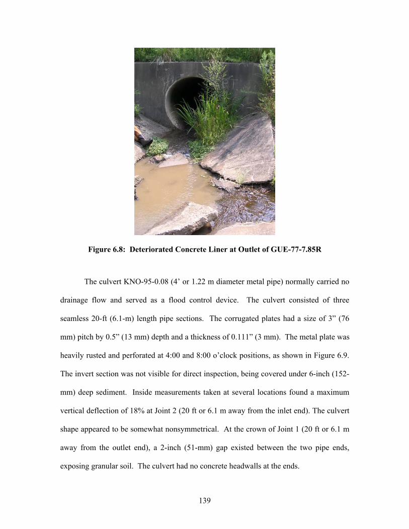
139
Figure 6.8: Deteriorated Concrete Liner at Outlet of GUE-77-7.85R
The culvert KNO-95-0.08 (4’ or 1.22 m diameter metal pipe) normally carried no
drainage flow and served as a flood control device. The culvert consisted of three
seamless 20-ft (6.1-m) length pipe sections. The corrugated plates had a size of 3” (76
mm) pitch by 0.5” (13 mm) depth and a thickness of 0.111” (3 mm). The metal plate was
heavily rusted and perforated at 4:00 and 8:00 o’clock positions, as shown in Figure 6.9.
The invert section was not visible for direct inspection, being covered under 6-inch (152-
mm) deep sediment. Inside measurements taken at several locations found a maximum
vertical deflection of 18% at Joint 2 (20 ft or 6.1 m away from the inlet end). The culvert
shape appeared to be somewhat nonsymmetrical. At the crown of Joint 1 (20 ft or 6.1 m
away from the outlet end), a 2-inch (51-mm) gap existed between the two pipe ends,
exposing granular soil. The culvert had no concrete headwalls at the ends.
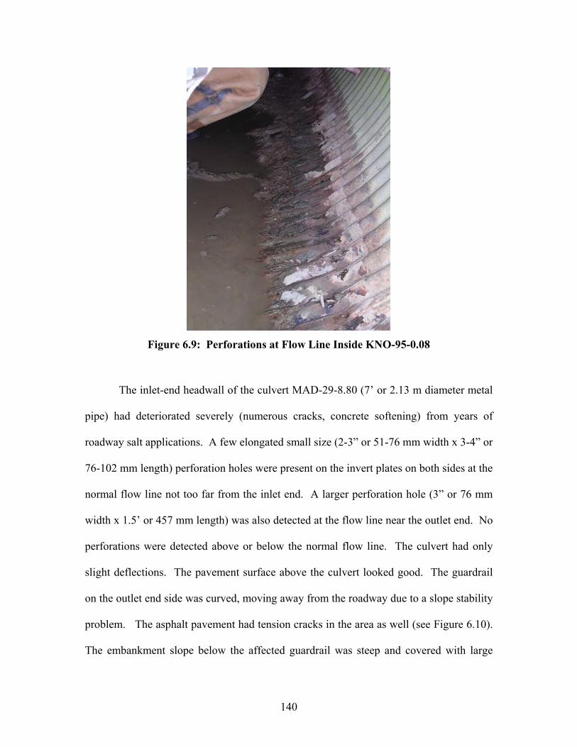
140
Figure 6.9: Perforations at Flow Line Inside KNO-95-0.08
The inlet-end headwall of the culvert MAD-29-8.80 (7’ or 2.13 m diameter metal
pipe) had deteriorated severely (numerous cracks, concrete softening) from years of
roadway salt applications. A few elongated small size (2-3” or 51-76 mm width x 3-4” or
76-102 mm length) perforation holes were present on the invert plates on both sides at the
normal flow line not too far from the inlet end. A larger perforation hole (3” or 76 mm
width x 1.5’ or 457 mm length) was also detected at the flow line near the outlet end. No
perforations were detected above or below the normal flow line. The culvert had only
slight deflections. The pavement surface above the culvert looked good. The guardrail
on the outlet end side was curved, moving away from the roadway due to a slope stability
problem. The asphalt pavement had tension cracks in the area as well (see Figure 6.10).
The embankment slope below the affected guardrail was steep and covered with large
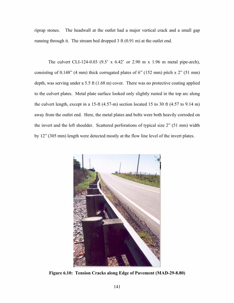
141
riprap stones. The headwall at the outlet had a major vertical crack and a small gap
running through it. The stream bed dropped 3 ft (0.91 m) at the outlet end.
The culvert CLI-124-0.03 (9.5’ x 6.42’ or 2.90 m x 1.96 m metal pipe-arch),
consisting of 0.148” (4 mm) thick corrugated plates of 6” (152 mm) pitch x 2” (51 mm)
depth, was serving under a 5.5 ft (1.68 m) cover. There was no protective coating applied
to the culvert plates. Metal plate surface looked only slightly rusted in the top arc along
the culvert length, except in a 15-ft (4.57-m) section located 15 to 30 ft (4.57 to 9.14 m)
away from the outlet end. Here, the metal plates and bolts were both heavily corroded on
the invert and the left shoulder. Scattered perforations of typical size 2” (51 mm) width
by 12” (305 mm) length were detected mostly at the flow line level of the invert plates.
Figure 6.10: Tension Cracks along Edge of Pavement (MAD-29-8.80)
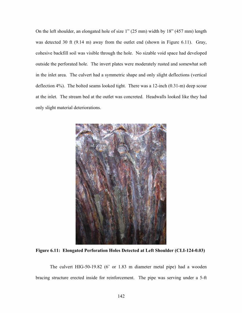
142
On the left shoulder, an elongated hole of size 1” (25 mm) width by 18” (457 mm) length
was detected 30 ft (9.14 m) away from the outlet end (shown in Figure 6.11). Gray,
cohesive backfill soil was visible through the hole. No sizable void space had developed
outside the perforated hole. The invert plates were moderately rusted and somewhat soft
in the inlet area. The culvert had a symmetric shape and only slight deflections (vertical
deflection 4%). The bolted seams looked tight. There was a 12-inch (0.31-m) deep scour
at the inlet. The stream bed at the outlet was concreted. Headwalls looked like they had
only slight material deteriorations.
Figure 6.11: Elongated Perforation Holes Detected at Left Shoulder (CLI-124-0.03)
The culvert HIG-50-19.82 (6’ or 1.83 m diameter metal pipe) had a wooden
bracing structure erected inside for reinforcement. The pipe was serving under a 5-ft
143
(1.52-m) cover. The pipe consisted of seamless sections joined together. The plate
thickness was 0.16” (4 mm), and its pitch and depth were 2.75” (70 mm) and 5/8” (16
mm). The invert area was rusted only on the surface. The culvert deflections were
relatively small. The embankment slopes were steep and covered with ODOT Type D
riprap rocks. It appeared that there had been a minor slope movement especially on the
outlet side. The guardrail had a deflection over two posts, and the pavement edge had
tension cracks. The west bound lane of Rt. 50 over the culvert had an asphalt patch over
it. There were no concrete headwalls at this site.
The culvert JAC-124-17.12 (7.25’ x 5.25’ or 2.21 m x 1.60 m metal pipe-arch)
was under only 2.5 ft (0.76 m) of cover. It had invert paving and was supported by
timber braces, as seen in Figure 6.12. The invert pavement had an area, about 10 ft (3.1
m) away from the outlet end, where the top 2-inch (51-mm) of concrete had eroded and
exposed some rusted rebars. The culvert consisted of three distinctive sections -- a 5-ft
(1.52-m) long seamless pipe at the inlet, a 15-ft (4.57-m) long multi-plate pipe-arch
section in the main barrel, and a 35-ft (10.67-m) seamless pipe section to the outlet. This
arrangement indicated that the original pipe-arch structure had been partially replaced in
the past. The corrugation size was 3” (76 mm) pitch by 1” (25 mm) depth through all
three sections. The metal plates were rusted on the invert. A few small perforation holes
were visible just above the concrete invert pavement. A 6” (152 mm) inward bulge was
found at 10:30 clock position, 9 ft (2.74 m) away from the inlet (in the older pipe-arch
section). The horizontal alignment of the culvert was not straight, due to the presence of
the three sections. The concrete headwall at the inlet end had deteriorated to the point

144
that it was nearly gone. There was no concrete headwall at the outlet end. There was a
13.5” (0.34 m) deep scour hole at the outlet. The pavement surface above the culvert had
two major (wider than 0.1” or 3 mm) transverse cracks running in parallel to the culvert
structure, as seen in Figure 6.13. The cracks appeared to be related to the culvert
performance. There was no noticeable dip on the pavement surface.
Figure 6.12: Timber Bracing Applied Inside JAC-124-17.12

145
Figure 6.13: Transverse Crack Detected Above JAC-124-17.12
The culvert PIK-32-15.96 (7’ or 2.13 m diameter metal pipe) was 391 ft (119.2 m)
long and was serving under a 16 ft (4.88 m) of soil fill. Its corrugation plates had a rare
size of 5” (127 mm) pitch by 1” (25 mm) depth with a thickness of 0.108” (3 mm). No
protective coating layer was applied to the culvert interior. However, a concrete invert
pavement existed along the culvert length. Conditions of the invert pavement layer were
good. The corrugated plates had minor dents and bulges at numerous locations. These
were most likely induced during construction. The culvert was experiencing only small
deflections (max. vertical deflection 4%). The headwall at each end looked good with
only a minor hairline crack running vertically above the crown. There was a 6-ft (1.83-m)
deep scour hole at the outlet end (see Figure 6.14).

146
Figure 6.14: A Large Scour Hole at Outlet of PIK-32-15.96
The twin pipes ADA-247-11.87 (4’ or 1.22 m diameter twin metal pipes) were
both 51 ft (15.5 m) long and consisted of non-sectional corrugated steel plate of size
2.625” (67 mm) pitch x 0.5” (13 mm) depth. Each pipe consisted of three sections:
Inlet Section (Length 6’ or 1.83 m; Wall Thickness 0.057” or 1.5 mm)
Main Barrel Section (Length 39’ or 11.89 m; Wall Thickness 0.108” or 3 mm)
Outlet Section (Length 6’ or 1.83 m; Wall Thickness 0.057” or 1.5 mm)
No protective coat was applied to the pipes. Initial walk-through of the two pipes
indicated that the “south” pipe had somewhat worse conditions. Because of the thin wall
thickness, the inlet end section of each pipe had a significant flattening at shoulder
locations. The diameter measurements taken inside the pipes showed only up to 2%
vertical and horizontal deflections. Each pipe had a slight sag in the middle. The steel
plate was mildly rusted in the crown and invert regions inside both pipes. No perforation
holes were detected in either pipe. There were no concrete headwalls erected at the ends.
147
Instead, 3-4 inch (76-102 mm) diameter riprap stones were dumped over the embankment
slopes around each end. Examination of the roadway surface revealed a transverse crack
running along the north pipe.
The culvert HOC-595-2.85 (7.67’ x 5.42’ or 2.34 m x 1.65 m metal pipe-arch),
installed in 1951, was 52 ft (15.85 m) in length. Its corrugated plates had a pitch of 6
inches (152 mm), a depth of 2 inches (51 mm), and a thickness of 0.182 inches (5 mm).
The height of cover over the culvert was only 12 inches (0.31 m). This was actually the
first culvert structure inspected in the current research project. There were a few serious
problems associated with this culvert. Inside dimensions taken at the mid-length section
were – rise 63.0” (1.60 m), span 91.0” (2.31 m), left span 46.75” (1.19 m), top mid-
ordinate 39.75” (1.0 m), top left chord 60.5” (1.54 m), top right chord 60.0” (1.52 m), top
left mid-ordinate 11.0” (0.28 m), and top right mid-ordinate 11.75” (0.30 m). These
dimensions indicated that the culvert had only small deflections and distortions (the shape
was not a problem). The horizontal alignment of the culvert looked good, but the
structure appeared to have a minor sag in the middle. A survey of general culvert
material conditions revealed light corrosion existed at isolated locations over the top, side,
and corner regions. A location of moderate rusting was detected at the crown 5 to 10 ft
(1.52 to 3.05 m) away from the outlet. The seams in the upper arc looked tight. The
metal plates on the invert were more heavily rusted and perforated extensively. The
deteriorated conditions of the invert plates became worse toward the outlet end. The
bedding was washed out under the culvert from the outlet end to about 13 ft (3.96 m)
away from the outlet end (see Figures 6.15 and 6.16). The headwall at the inlet was
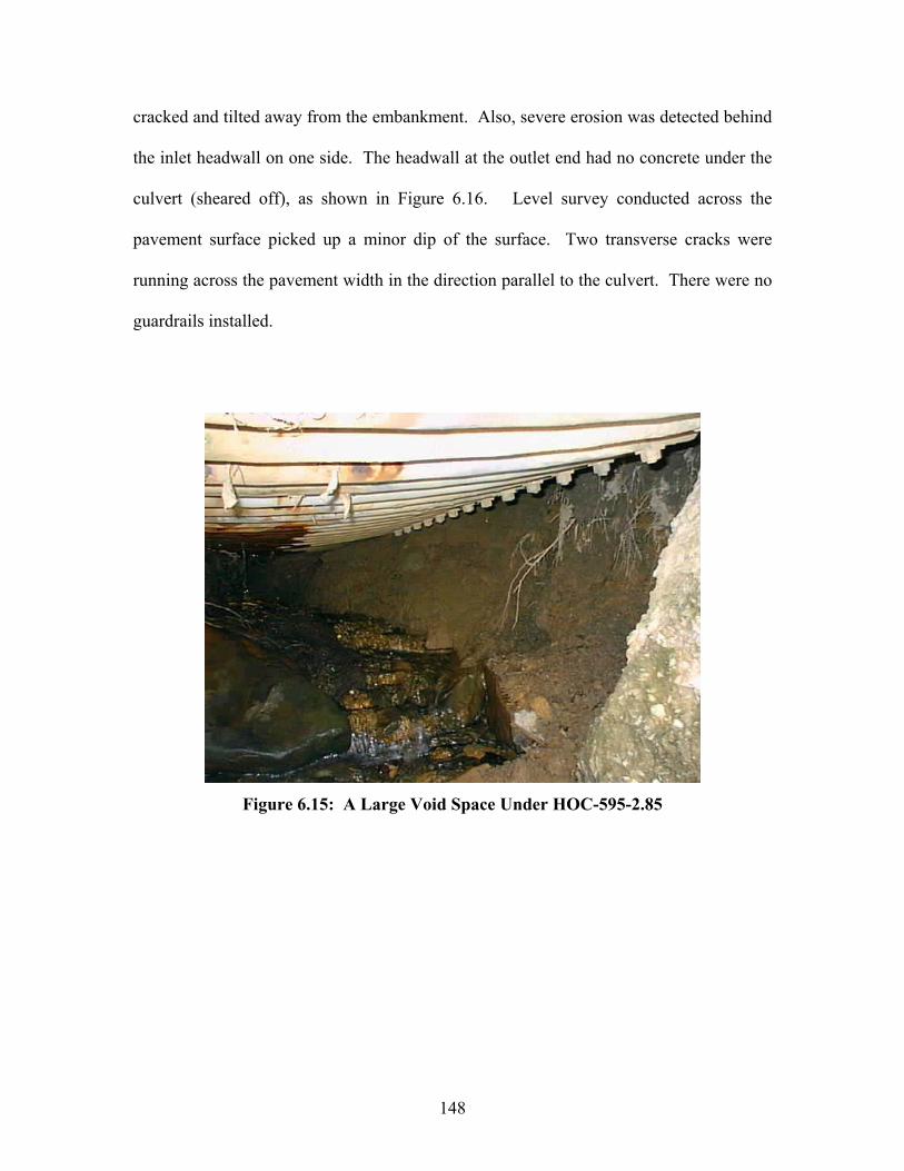
148
cracked and tilted away from the embankment. Also, severe erosion was detected behind
the inlet headwall on one side. The headwall at the outlet end had no concrete under the
culvert (sheared off), as shown in Figure 6.16. Level survey conducted across the
pavement surface picked up a minor dip of the surface. Two transverse cracks were
running across the pavement width in the direction parallel to the culvert. There were no
guardrails installed.
Figure 6.15: A Large Void Space Under HOC-595-2.85

149
Figure 6.16: Shear Failure of Outlet Headwall at HOC-595-2.85
The culvert HOC-664-17.16 (8.6’ x 5.9’ or 2.62 m x 1.80 m metal pipe-arch) was
installed in 1959 and received no repairs/modifications over the years. It was constructed
with sectional plates having a 6-inch (152-mm) pitch, 2-inch (51-mm) depth, and 0.20-
inch (5-mm) thickness. The culvert was skewed at 45˚, and its 66-ft (20.1-m) length was
under 1 to 1.5 ft (0.31 to 0.46 m) of cover. No protective coating was applied to the
plates inside. The invert section of the culvert was buried under up to 11-inch (0.28 m)
deep sediment. The corner plates were moderately rusted in the inlet section. However,
no perforation holes or missing bolts were observed in the area. Rise and span
measurements taken inside the culvert showed that the structure had experienced only
small deflections. The culvert appeared to be experiencing a minor sag in the mid-length
section. At a section 13 ft (3.96 m) away from the outlet end, moderately rusted plates
150
and bolts were detected at a seam located in the top region. The headwalls of the culvert
exhibited an advanced stage of material deterioration. At the inlet end, the headwall had
numerous cracks with a portion of the wall missing. In the right shoulder region, the
culvert plate and the headwall concrete were separated by a 1-inch (25-mm) gap. At the
outlet end, the conditions of the headwall were even worse. The full-height headwall had
no concrete remaining above the culvert, with a rusted rebar completely exposed. Also,
the headwall appeared to have rotated away from the roadway embankment. A 12-inch
(0.31-m) deep minor scour hole existed at the outlet end. The roadway surface had
numerous cracks above the culvert. There were no guardrails at this site.
The culvert HOC-664-22.4 (7’ or 2.13 m diameter metal pipe) was 48 years old at
the time of field inspection. It was assembled with standard corrugated sectional plates
(6-inch or 152-mm pitch x 2-inch or 51-mm depth) and had a total length of 100 ft (30.5
m). The plate thickness was 0.14 in (4 mm). The plates had no protective coating over
them. The culvert was under a soil cover of 12 ft (3.66 m). Horizontal and vertical
diameters were measured at 10-ft (3.05-m) intervals along the culvert length. The
measurements are listed in Table 6.9 below. These measurements indicate that the
serious condition existed mostly within the first 20 ft (6.10 m) from the inlet end. The
team observed that the culvert section in this area consisted of severely distorted plates,
ripped apart at seams. A large seam opening on the invert created a hole where the
drainage flow could plunge and scour the bedding soil (see Figure 6.17). According to a
local resident, there was a major flood in this area in the past. The inlet headwall and
section were damaged under an accumulation of large debris during the flood event. The
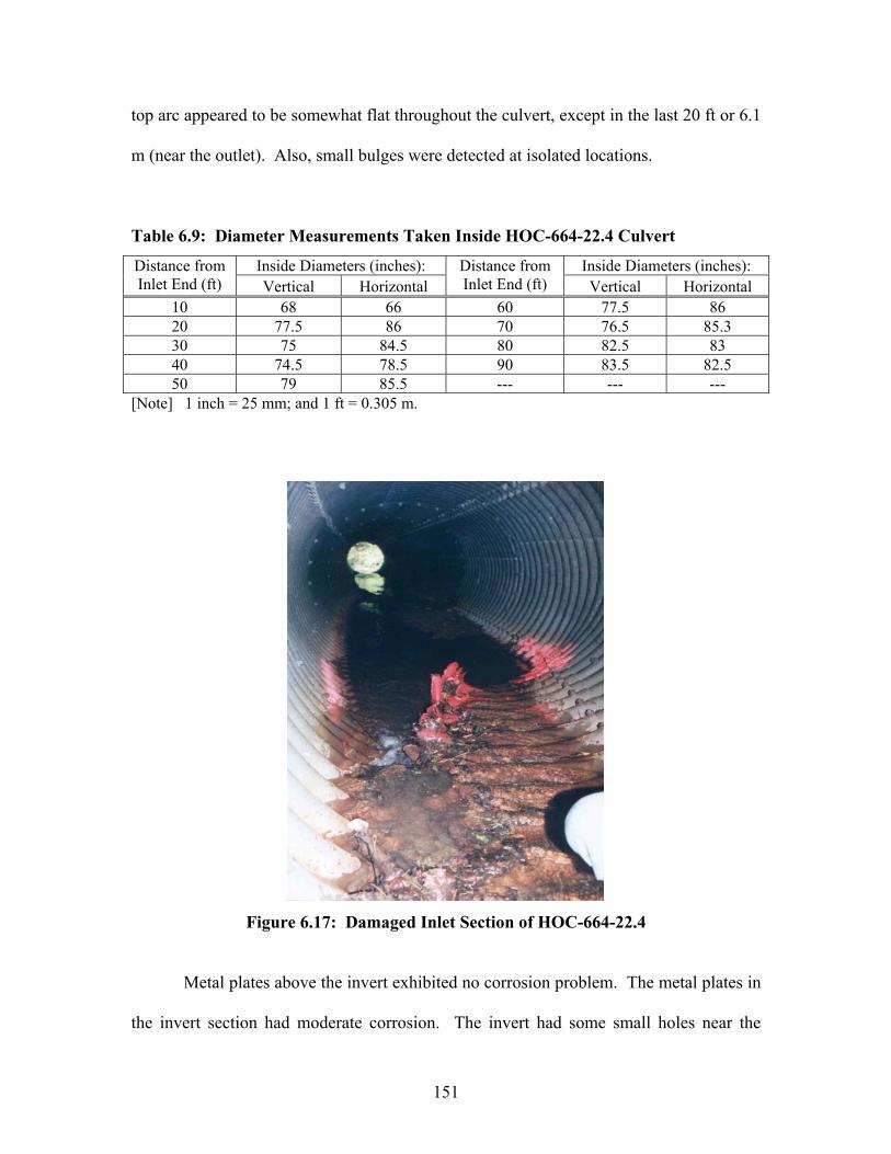
151
top arc appeared to be somewhat flat throughout the culvert, except in the last 20 ft or 6.1
m (near the outlet). Also, small bulges were detected at isolated locations.
Table 6.9: Diameter Measurements Taken Inside HOC-664-22.4 Culvert
Inside Diameters (inches): Inside Diameters (inches): Distance from Inlet End (ft) Vertical Horizontal
Distance from Inlet End (ft) Vertical Horizontal
10 68 66 60 77.5 86 20 77.5 86 70 76.5 85.3 30 75 84.5 80 82.5 83 40 74.5 78.5 90 83.5 82.5 50 79 85.5 --- --- ---
[Note] 1 inch = 25 mm; and 1 ft = 0.305 m.
Figure 6.17: Damaged Inlet Section of HOC-664-22.4
Metal plates above the invert exhibited no corrosion problem. The metal plates in
the invert section had moderate corrosion. The invert had some small holes near the
152
outlet end and a medium sized perforation hole at the outlet end. A small remnant of the
headwall was found on one side at the inlet. It was clear that the headwall had either
totally failed or had been removed at the entrance. The headwall at the outlet was still
largely intact. The section underneath the culvert had a portion missing and cracks
propagating. The drainage flow was flowing under the invert and impacting the concrete
surface. The channel bed was much lower than the invert elevation at the outlet. The
roadway surface showed two transverse cracks (width > 0.1” or 3 mm) running across the
entire pavement width. Guardrails appeared to be in good service conditions.
The culvert GAL-7-21.3 (2.5’ or 0.76 m diameter metal pipe) had an age of 64
years, a length of 108 ft (32.9 m) and a slope of 15%, serving under 6 ft (1.8 m) of cover.
According to ODOT, a hole had surfaced in the shoulder section of Rt. 7 above the
culvert (on the inlet side) about two years ago. The hole was covered with a thick steel
plate as a temporary measure. Inspection of the aged culvert revealed that it consisted of
three distinct sections. The section at the inlet was a 28.5-inch (0.72-m) diameter CMP
(corrugation pitch 2.5” or 64 mm; corrugation depth 0.5” or 13 mm; thickness 0.1” or 3
mm) with a length of 22 ft (6.71 m). This section had its invert completely rusted out
along its entire length. The drainage water was flowing on top of exposed soil,
underneath the culvert. The channel above the inlet end was basically a ditch on a steep
slope. There were numerous signs of erosion problems along the channel. The full-height
concrete headwall at the inlet end was suffering from minor material deteriorations but
free from any major cracks or movements. The outlet section was also 22 ft (6.71 m) in
length and had the same features as the inlet section. The invert of the outlet section was

153
also rusted away, leaving a 6-inch (152-mm) wide gap at the bottom along the length.
Drainage flow was flowing on top of the soil below the culvert and causing erosion. The
culvert in the main barrel section had a diameter of 24 inches (0.61 m). It was disjoined
from the end sections. The main culvert section appeared to have a very mild slope and
was nearly half full of water. It had moderate deflections and a few small bulges on the
sides. A medium-size void was developing within the embankment fill at each location
of joint opening. The hole in the shoulder area (on the inlet side) was determined to be
located immediately above the joint opening between the inlet and main sections. A
similar hole was detected above the culvert joint on the outlet side, but this hole surfaced
to the embankment slope. A steady stream of drainage water was seeping out on the
slope, about 10 ft (3.1 m) away from the culvert outlet end. This offered additional
evidence that the soil fill surrounding the culvert was suffering from piping (internal
erosion) problems. The culvert was replaced during May-June of 2003. The contractor
retained by ODOT performed jack and bore operations next to the existing culvert to
install a new 36-inch (0.91-m) diameter CMP (length 78 ft or 23.8 m; slope 7%). The
original culvert was filled with grout to cease its function as a drainage structure.
The culvert MEG-681-7.94 (6’ or 1.83 m diameter metal pipe) was one of the few
culverts with a protective coating as well as invert paving applied to the culvert. The
drainage flow was very rapid, and some large debris was located at the inlet end. The
invert pavement layer had been largely removed. The bituminous coat was still mostly
intact in the top arc section (see Figure 6.18). The culvert plates were moderately rusted
in the corner and invert. No perforation holes were detected. Hammering by a pick
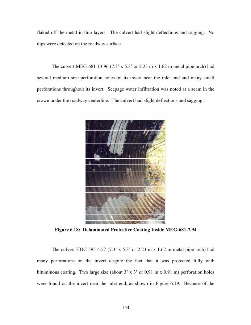
154
flaked off the metal in thin layers. The culvert had slight deflections and sagging. No
dips were detected on the roadway surface.
The culvert MEG-681-13.96 (7.3’ x 5.3’ or 2.23 m x 1.62 m metal pipe-arch) had
several medium size perforation holes on its invert near the inlet end and many small
perforations throughout its invert. Seepage water infiltration was noted at a seam in the
crown under the roadway centerline. The culvert had slight deflections and sagging.
Figure 6.18: Delaminated Protective Coating Inside MEG-681-7.94
The culvert HOC-595-4.57 (7.3’ x 5.3’ or 2.23 m x 1.62 m metal pipe-arch) had
many perforations on the invert despite the fact that it was protected fully with
bituminous coating. Two large size (about 3’ x 3’ or 0.91 m x 0.91 m) perforation holes
were found on the invert near the inlet end, as shown in Figure 6.19. Because of the

155
extent of perforation in this area, the drainage flow was moving below the invert and
causing up to 12-inch (0.31-m) deep scouring under the culvert. Invert plates were
heavily rusted at the outlet as well. One 2’ x 2’ (0.61 m x 0.61 m) perforation hole was
discovered on the invert near the outlet end. Invert of the main barrel had small
perforations scattered throughout. The drainage water was flowing over the invert in the
main barrel section. The bituminous coat was nonexistent over the invert and spotty over
the sides and top arc. General shape of the culvert appeared to be good, with vertical
deflection only about 3%. The headwall at each end had at least one major crack and
showed signs of minor material deterioration.
Figure 6.19: Large Perforation Holes Through Invert of HOC-595-4.57
156
The culvert WAS-339-15.25 (6’ or 1.83 m diameter metal pipe) was under a 6-ft
(1.83-m) soil cover. The structural plates were covered with bituminous coating, had size
of 6” (152 mm) pitch x 2” (51 mm) depth, and a thickness of 0.167” (4 mm). The
protective coat was mostly intact but delaminated at isolated locations within the top arc.
The coating was nearly nonexistent in the corner and invert sections. The invert plates
were rusted but still relatively solid. There were medium-sized perforation holes at the
normal flow line throughout the culvert length. The culvert shape looked good. No
stress cracks or seam opening were found inside. The headwall at each end had minor
material deteriorations such as spalling and up to ¼” (6 mm) deep scaling. There was a
moderate degree of erosion taking place on the embankment slope behind the headwall at
the inlet. Five guardrail posts near the outlet end were leaning away from the roadway
surface, implying some slope movements over the years. At the outlet end, the stream
bed was 12 inches (0.31 m) lower than the culvert invert.
The culvert WAS-60-4.84 (8’ or 2.44 m diameter metal pipe) consisted of
structural plates characterized by a 6” (152 mm) x 2” (51 mm) corrugation size and a
thickness of 0.147” (4 mm). It was serving under a 21 ft (6.4 m) of soil cover. The plates
had no protective coating and were rusted extensively in the invert region. The invert
plates were relatively soft. Medium size perforations were detected only in the inlet and
outlet sections. One side of the inlet headwall was tilted away from the embankment
slope. The soil it used to retain had been washed off, exposing the side of the culvert.
The headwall at the outlet end looked fine. The culvert shape appeared relatively poor in
the main barrel, especially at 32.2 ft (9.8 m) away from the inlet end. Up to a ½” (13 mm)

157
seam opening was detected in the shoulder area. Inside measurements showed that the
culvert had a 6% vertical deflection and a 27% reduction in the top mid-ordinate. These
measurements indicated that the top arc had become flat.
The culvert LAK-90-14.0 (15’ or 4.57 m diameter metal pipe) was the largest size
metal culvert inspected in the current study. According to ODOT records, the invert of
this culvert was paved with concrete in 2002. The plates in this culvert had a size of 6”
(152 mm) pitch by 2” (51 mm) depth (thickness 0.288” or 7 mm). No protective coat had
been applied to the plates. The culvert had a total length of 420 ft (128.0 m) and was
placed under a 40 ft (12.2 m) cover. The metal plates had only slight discoloration and
rusting. The culvert’s cross-sectional shape looked round with no areas of flattening.
The invert pavement looked good with only occasional hairline cracks and minor dents.
No measurable sediment accumulation was recorded due to rapid drainage flow. The
concrete headwall at the inlet had minor material deteriorations. In contrast, the headwall
at the outlet looked to be rotated away from the embankment by as much as 5˚. A major
crack was observed on the concrete wall below the pipe invert. There were some signs of
erosion behind this headwall.
The culvert LAK-90-4.2 (10’ or 3.1 m diameter metal pipe) was the longest
(length 922 ft or 281 m) metal culvert structure in the inspection program. The plates in
this culvert had a size of 6” (152 mm) pitch by 2” (51 mm) depth (thickness 0.278” or 7
mm). No protective coat had been applied to the plates. Each culvert end was mitered to
conform to the embankment slope. The exposed ends of the culvert had mildly rusted
158
spots. Conditions of this culvert were in many ways similar to those of the culvert LAK-
90-14.0. The plate surfaces inside the culvert looked good, except in the section near the
outlet end where minor to moderate degree of rusting existed at isolated seams. No
perforation holes were found anywhere on the plates. No measurable sediment
accumulation was recorded due to rapid drainage flow. The invert pavement looked good
with only occasional hairline cracks and minor dents. The concrete headwall at the outlet
end looked slightly rotated away from the embankment. A few cracks were found on the
headwall in the culvert haunch area. There was sign of soil erosion behind the headwall
at the outlet end. Also, a large medium-depth scour hole was present in the stream just
below the outlet end. At the inlet end, two concrete-lined ditches carried the surface
drainage flow into the concrete apron in front of the culvert inlet. The concrete apron by
the inlet end was partially scoured underneath.
6.2.4 Conditions Detected at Thermoplastic Pipe Culvert Sites
During the field inspection program, some specific conditions were observed at
the thermoplastic pipe culvert sites. Table 6.10 lists these specific conditions
encountered, and Table 6.11 shows the type of conditions that existed at each plastic pipe
culvert site. It is noted here that none of the conditions existed at other sites was
detected at three thermoplastic culvert sites on Rt. 33 Bypass.

159
Table 6.10: List of Field Conditions Detected at Thermoplastic Pipe Sites No. Description of Condition 01 Vertical deflection is 7.5% or larger. 02 Horizontal deflection is 7.5% or larger. 03 The top arc is relatively flat. 04 The bottom arc is relatively flat. 05 Dimples exist in the region between the shoulder and springline positions, which represent
localized buckling of the internal hydraulic liner (applies to HDPE pipes only). 06 Moderate misalignment exists at the joints. 07 Localized bulges are detected between the shoulder and haunch regions near the joint. 08 Interior liner is separated from the structural wall near the joint at isolated locations. 09 Moderate to severe sediment accumulation is detected inside the culvert. 10 A moderate to large scour hole exists in front of the inlet or outlet end. 11 Pavement has transverse cracks running all the way through in the direction parallel to the
culvert.12 The embankment slope is showing signs of slope stability problem. [Note] Numbers represent the characteristic conditions in Table 6.11.
Table 6.11: Existence of Characteristic Conditions at Thermoplastic Pipe Sites Characteristic Condition No.:
Dist. Culvert I.D. 1 2 3 4 5 6 7 8 9 10 11 1205 FAI-33b-Sta.
446+92
05 PER-13-11.14 05 FAI-33b-Sta.
587+96 05 FAI-22-Sta.
17+20 05 FAI-33b-SR18-
Sta. 86+00
05 FAI-33b-SR18-Sta. 96+00
05 FAI-33b-Ramp J (Sta. 488+07)
10 MEG-124-30.17 10 HOC-327-2.70 10 NOB-145-3.59 [Note] See Table 6.10 for descriptions of each characteristic condition.
Deflections measured inside the thermoplastic pipe culverts are listed in Table
6.12. The vertical deflection was less than 10% inside all the thermoplastic pipe culverts.
The ratio between the vertical and horizontal deflections varied widely among the ten
field sites.

160
Table 6.12: Measured Deflections of Thermoplastic Pipe Culverts Deflection:
Dist. Culvert I.D. Culvert Description Vertical Horizontal Note05 FAI-33b-Sta. 446+92 60” Dia. Corrug. HDPE - 7.9% 7.9% Under construction. 05 PER-13-11.14 42” Dia. Corrug. HDPE - 7.1% 2.4% --05 FAI-33b-Sta. 587+96 48” Dia. PVC - 6.3 % 3.1% Under construction. 05 FAI-22-Sta. 17+20 36” Dia. PVC - 2.1% < 1% Under construction. 05 FAI-33b-SR18-Sta.
86+00 36” Dia. Corrug. HDPE - 3%
(min.) NA Under service road;
Under construction. 05 FAI-33b-SR18-Sta.
96+00 36” Dia. PVC - 2% < 1% Under service road;
Under construction. 05 FAI-33b-Ramp J
(Sta. 488+07) 30” Dia. PVC < - 1% < 1% Under ramp section;
Under construction. 10 MEG-124-30.17 48” Dia. HC-HDPE - 8.5% 2.0% --10 HOC-327-2.70 42” Dia. Corrug. HDPE - 7.1%
(min.) 10.7% --
10 NOB-145-3.59 24” Dia. Corrug. HDPE*
- 8.3% 8.3% pH = 4.6
* [Note] This pipe had no hydraulic liner inside; 1” = 25 mm.
Frequencies of the specific conditions cited at the thermoplastic pipe culvert sites
are summarized in Table 6.13. Condition Nos. 1 (vertical deflection > 7.5%), 2
(horizontal deflection > 7.5%), 5 (local buckling of hydraulic liner), and 6 (misalignment
at joint) were detected somewhat more frequently than the other conditions. In contrast,
Condition Nos. 8 (separation of hydraulic liner), 10 (scour hole at inlet or outlet), and 12
(embankment slope instability) were encountered the least frequently.
Table 6.13: Frequency of Conditions at Thermoplastic Pipe Culvert Sites Condition Frequency % Condition Frequency %
1 5 (out of 25) 20 7 2 (out of 25) 8 2 4 (out of 25) 16 8 1 (out of 25) 4 3 2 (out of 25) 8 9 3 (out of 25) 12 4 2 (out of 25) 8 10 1 (out of 25) 4 5 4 (out of 25) 16 11 3 (out of 25) 12 6 4 (out of 25) 16 12 1 (out of 25) 4
Detailed descriptions of the conditions encountered at each of the ten thermoplastic pipe
culvert sites are presented in the following paragraphs.

161
According to an ODOT field inspector, a heavy construction equipment ran over
the 60-inch (1.52-m) diameter HDPE pipe (FAI-33b-Sta. 446+92) when the height of
cover was only 5 ft (1.52 m). As a result, the pipe deflected vertically and developed
localized buckling of the internal hydraulic liner in the springline region. This pipe was
backfilled with ODOT Item 304 Type 1 (sand). All indications were that the sand
backfill was not properly compacted during the installation of this culvert. Therefore, the
installation conditions of this pipe represented one of the worst conditions among the
thermoplastic culverts inspected in the project.
The 42-inch (1.07-m) diameter HDPE pipe (PER-13-11.14) consisted of three
standard length sections, giving it a total length of 60 ft (18.3 m). According to the
manufacturer, this pipe product was manufactured by an obsolete process. Minor
dimpling of the internal hydraulic lining existed at the springline positions from about 6 ft
(1.83 m) inside the inlet end to about 5 ft (1.52 m) away from the outlet end. In the
middle section, the bottom arc appeared flat. Cross-sectional shape was like an oval and
symmetric. There were no headwalls at the ends. Roadway embankment slopes
surrounding the pipe inlet/outlet were treated with ODOT Type “C” rock protection. The
roadway surface had two transverse cracks running parallel to the skewed pipeline
structure (see Figure 6.20). The cover height over the pipe was only 1.5 ft (0.46 m). A
deep scour hole was found below the outlet end.

162
Figure 6.20: Skewed Transverse Cracks Over PER-13-11.14
The 48-inch (1.22-m) diameter PVC pipe (FAI-33b-Sta. 587+96) had a smooth
wall. It consisted of thirteen standard length sections and a short section added next to a
manhole (total pipeline length 173.8 ft or 53.0 m). The height of cover was 14 ft (4.3 m)
on the day the culvert was inspected. The final construction plan calls for 17 ft (5.2 m)
cover. The headwalls, as well as the bottom half of the pipe, were submerged in drainage
water. According to the inside diameter measurements, the pipe was experiencing less
than 5% deflections. The pipe material visible above the water surface looked new and
free from any defects. Figure 6.21 shows a general interior view of this pipe.
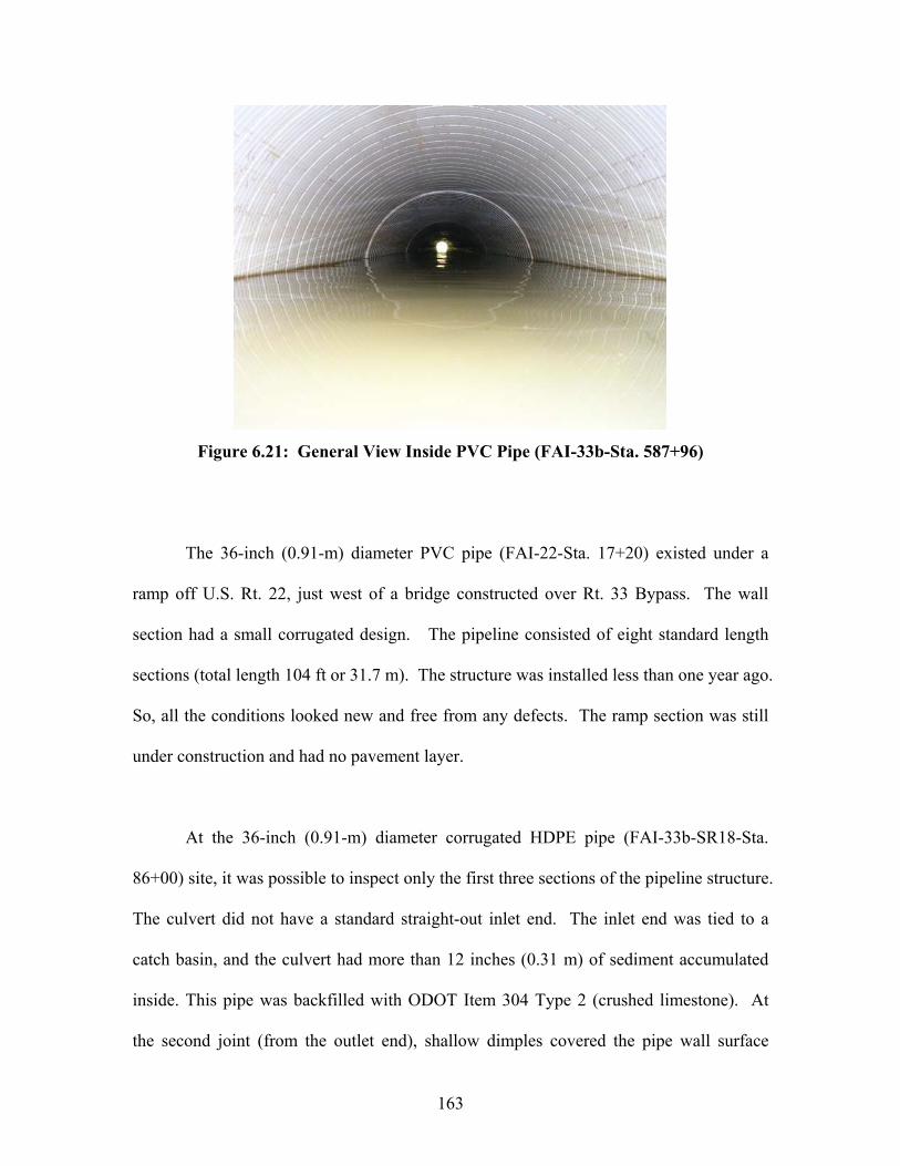
163
Figure 6.21: General View Inside PVC Pipe (FAI-33b-Sta. 587+96)
The 36-inch (0.91-m) diameter PVC pipe (FAI-22-Sta. 17+20) existed under a
ramp off U.S. Rt. 22, just west of a bridge constructed over Rt. 33 Bypass. The wall
section had a small corrugated design. The pipeline consisted of eight standard length
sections (total length 104 ft or 31.7 m). The structure was installed less than one year ago.
So, all the conditions looked new and free from any defects. The ramp section was still
under construction and had no pavement layer.
At the 36-inch (0.91-m) diameter corrugated HDPE pipe (FAI-33b-SR18-Sta.
86+00) site, it was possible to inspect only the first three sections of the pipeline structure.
The culvert did not have a standard straight-out inlet end. The inlet end was tied to a
catch basin, and the culvert had more than 12 inches (0.31 m) of sediment accumulated
inside. This pipe was backfilled with ODOT Item 304 Type 2 (crushed limestone). At
the second joint (from the outlet end), shallow dimples covered the pipe wall surface
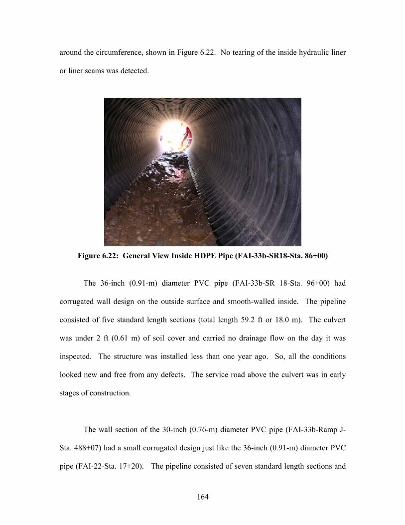
164
around the circumference, shown in Figure 6.22. No tearing of the inside hydraulic liner
or liner seams was detected.
Figure 6.22: General View Inside HDPE Pipe (FAI-33b-SR18-Sta. 86+00)
The 36-inch (0.91-m) diameter PVC pipe (FAI-33b-SR 18-Sta. 96+00) had
corrugated wall design on the outside surface and smooth-walled inside. The pipeline
consisted of five standard length sections (total length 59.2 ft or 18.0 m). The culvert
was under 2 ft (0.61 m) of soil cover and carried no drainage flow on the day it was
inspected. The structure was installed less than one year ago. So, all the conditions
looked new and free from any defects. The service road above the culvert was in early
stages of construction.
The wall section of the 30-inch (0.76-m) diameter PVC pipe (FAI-33b-Ramp J-
Sta. 488+07) had a small corrugated design just like the 36-inch (0.91-m) diameter PVC
pipe (FAI-22-Sta. 17+20). The pipeline consisted of seven standard length sections and
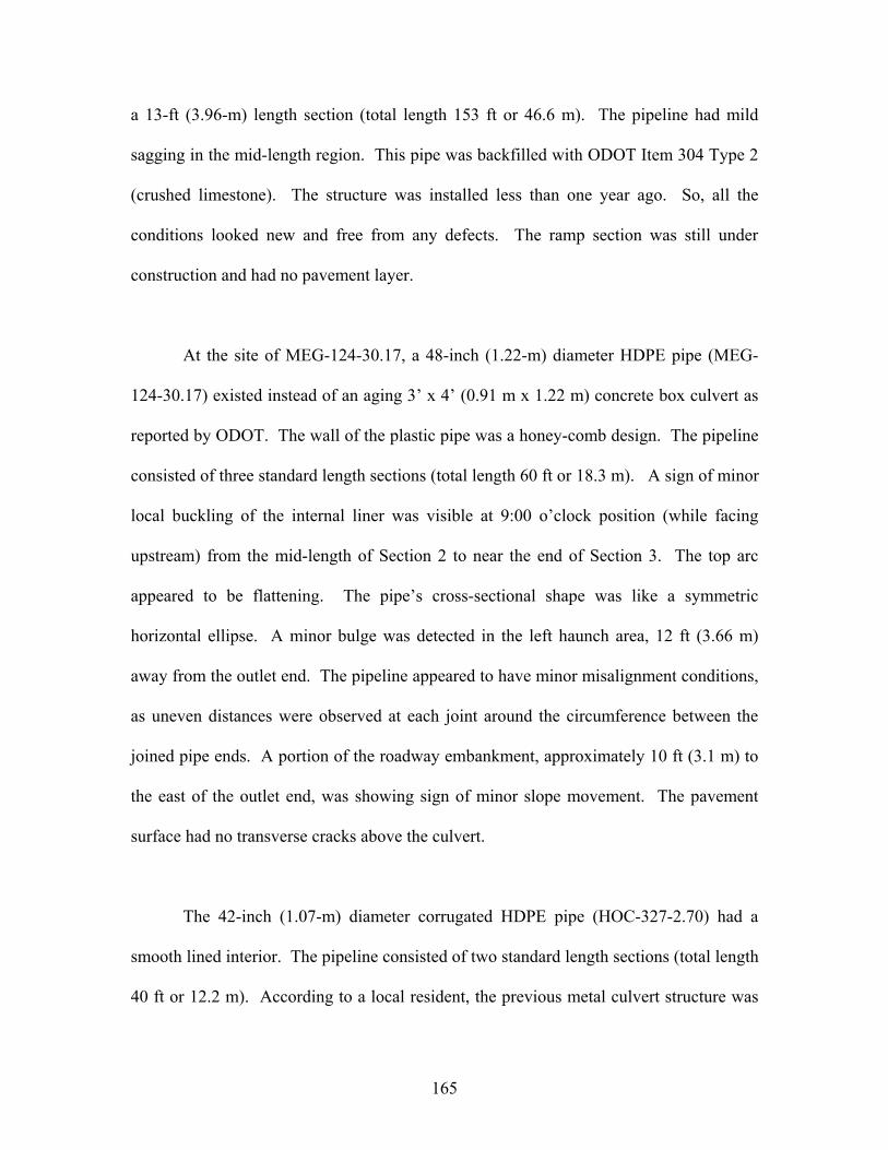
165
a 13-ft (3.96-m) length section (total length 153 ft or 46.6 m). The pipeline had mild
sagging in the mid-length region. This pipe was backfilled with ODOT Item 304 Type 2
(crushed limestone). The structure was installed less than one year ago. So, all the
conditions looked new and free from any defects. The ramp section was still under
construction and had no pavement layer.
At the site of MEG-124-30.17, a 48-inch (1.22-m) diameter HDPE pipe (MEG-
124-30.17) existed instead of an aging 3’ x 4’ (0.91 m x 1.22 m) concrete box culvert as
reported by ODOT. The wall of the plastic pipe was a honey-comb design. The pipeline
consisted of three standard length sections (total length 60 ft or 18.3 m). A sign of minor
local buckling of the internal liner was visible at 9:00 o’clock position (while facing
upstream) from the mid-length of Section 2 to near the end of Section 3. The top arc
appeared to be flattening. The pipe’s cross-sectional shape was like a symmetric
horizontal ellipse. A minor bulge was detected in the left haunch area, 12 ft (3.66 m)
away from the outlet end. The pipeline appeared to have minor misalignment conditions,
as uneven distances were observed at each joint around the circumference between the
joined pipe ends. A portion of the roadway embankment, approximately 10 ft (3.1 m) to
the east of the outlet end, was showing sign of minor slope movement. The pavement
surface had no transverse cracks above the culvert.
The 42-inch (1.07-m) diameter corrugated HDPE pipe (HOC-327-2.70) had a
smooth lined interior. The pipeline consisted of two standard length sections (total length
40 ft or 12.2 m). According to a local resident, the previous metal culvert structure was
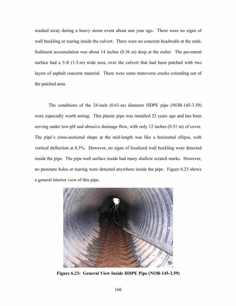
166
washed away during a heavy storm event about one year ago. There were no signs of
wall buckling or tearing inside the culvert. There were no concrete headwalls at the ends.
Sediment accumulation was about 14 inches (0.36 m) deep at the outlet. The pavement
surface had a 5-ft (1.5-m) wide area, over the culvert that had been patched with two
layers of asphalt concrete material. There were some transverse cracks extending out of
the patched area.
The conditions of the 24-inch (0.61-m) diameter HDPE pipe (NOB-145-3.59)
were especially worth noting. This plastic pipe was installed 23 years ago and has been
serving under low-pH and abrasive drainage flow, with only 12 inches (0.31 m) of cover.
The pipe’s cross-sectional shape at the mid-length was like a horizontal ellipse, with
vertical deflection at 8.3%. However, no signs of localized wall buckling were detected
inside the pipe. The pipe wall surface inside had many shallow scratch marks. However,
no puncture holes or tearing were detected anywhere inside the pipe. Figure 6.23 shows
a general interior view of this pipe.
Figure 6.23: General View Inside HDPE Pipe (NOB-145-3.59)

167
Field performance of the plastic pipes installed at the Rt. 33 bypass project in
Fairfield County, District 5, was evaluated on two occasions (April 03, April 04) during
the current project. No significant deteriorations in their field performance were
observed for any of the culverts, while the construction progressed at the site. The
highway project will not be completed until 2007.
6.3 BASIC ANALYSIS
This section of Chapter 6 attempts to conduct a basic analysis of the data collected
during the field culvert inspection phase. More advanced data analysis will be presented
in Chapter 7, where some multi-variable statistical methods are applied to identify
important parameters and verify the current ODOT approaches in inspecting the highway
culverts and estimating durability of culvert materials.
6.3.1 Basic Analysis of Data Collected at Concrete Culvert Sites
None of the concrete culverts inspected in the project had any protective coating
applied to the concrete surface. No major alignment problems were noticed at any of the
concrete culvert sites. Deteriorated concrete headwall existed at many sites where the
culvert was at least 35 years old and the soil cover was less than 5 ft (1.52 m). This
suggests that the main cause for the severe concrete deterioration might be repeated
chloride attacks (from deicing salt applications) and freeze-thaw cycles. The roadway
surface had no settlement problems at all the concrete culvert sites. The service life for
concrete culvert structures under Ohio roadways may be limited to 70 to 80 years. Table
6.14 summarizes the rating scores each concrete culvert received according to the
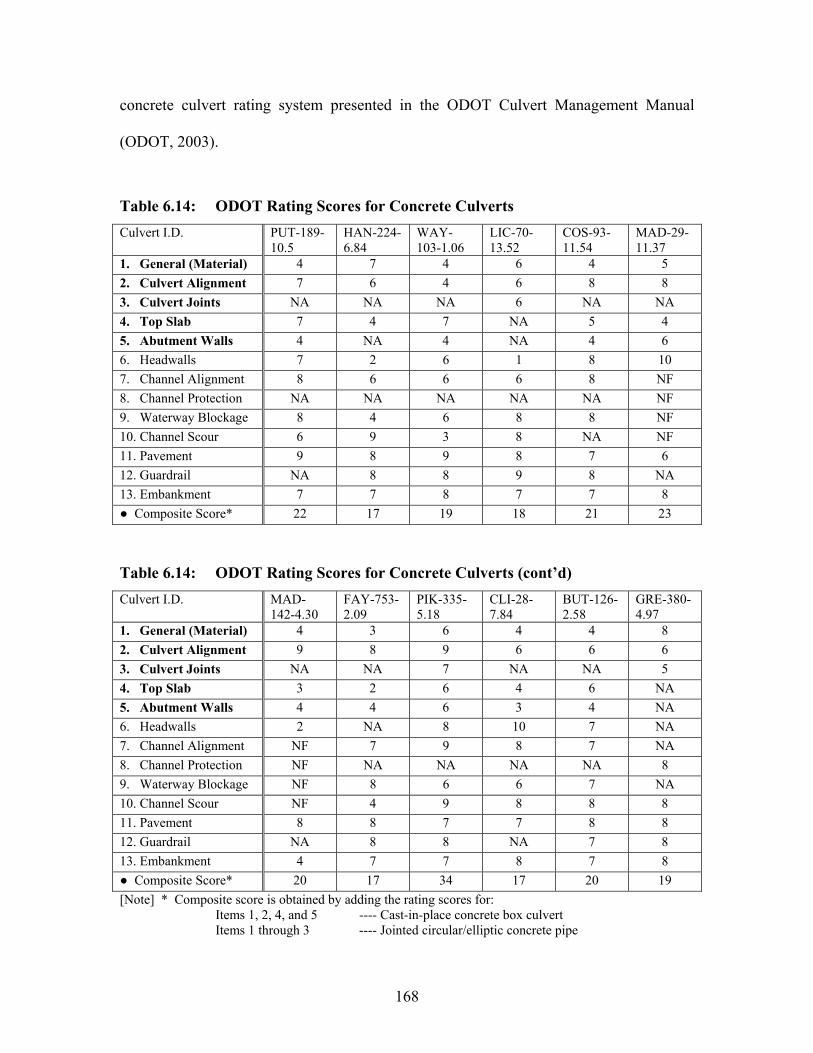
168
concrete culvert rating system presented in the ODOT Culvert Management Manual
(ODOT, 2003).
Table 6.14: ODOT Rating Scores for Concrete Culverts
Culvert I.D. PUT-189-10.5
HAN-224-6.84
WAY-103-1.06
LIC-70-13.52
COS-93-11.54
MAD-29-11.37
1. General (Material) 4 7 4 6 4 5 2. Culvert Alignment 7 6 4 6 8 8 3. Culvert Joints NA NA NA 6 NA NA 4. Top Slab 7 4 7 NA 5 4 5. Abutment Walls 4 NA 4 NA 4 6 6. Headwalls 7 2 6 1 8 10 7. Channel Alignment 8 6 6 6 8 NF 8. Channel Protection NA NA NA NA NA NF 9. Waterway Blockage 8 4 6 8 8 NF 10. Channel Scour 6 9 3 8 NA NF 11. Pavement 9 8 9 8 7 6 12. Guardrail NA 8 8 9 8 NA 13. Embankment 7 7 8 7 7 8
Composite Score* 22 17 19 18 21 23
Table 6.14: ODOT Rating Scores for Concrete Culverts (cont’d)
Culvert I.D. MAD-142-4.30
FAY-753-2.09
PIK-335-5.18
CLI-28-7.84
BUT-126-2.58
GRE-380-4.97
1. General (Material) 4 3 6 4 4 8 2. Culvert Alignment 9 8 9 6 6 6 3. Culvert Joints NA NA 7 NA NA 5 4. Top Slab 3 2 6 4 6 NA 5. Abutment Walls 4 4 6 3 4 NA 6. Headwalls 2 NA 8 10 7 NA 7. Channel Alignment NF 7 9 8 7 NA 8. Channel Protection NF NA NA NA NA 8 9. Waterway Blockage NF 8 6 6 7 NA 10. Channel Scour NF 4 9 8 8 8 11. Pavement 8 8 7 7 8 8 12. Guardrail NA 8 8 NA 7 8 13. Embankment 4 7 7 8 7 8
Composite Score* 20 17 34 17 20 19 [Note] * Composite score is obtained by adding the rating scores for: Items 1, 2, 4, and 5 ---- Cast-in-place concrete box culvert Items 1 through 3 ---- Jointed circular/elliptic concrete pipe

169
Table 6.14: ODOT Rating Scores for Concrete Culverts (cont’d)
Culvert I.D. HIG-124-25.75
HOC-216-1.99
HOC-78-1.05
HOC-216-3.25
HOC-216-3.43
MRG-78-11.34
1. General (Material) 9 8 6 7 7 7 2. Culvert Alignment 8 9 9 9 9 9 3. Culvert Joints 8 NA NA NA NA NA 4. Top Slab NA 6 5 7 7 7 5. Abutment Walls NA 7 6 7 7 7 6. Headwalls 9 10 2 6 2 8 7. Channel Alignment 8 6 6 8 8 7 8. Channel Protection NA NA NA NA NA NA 9. Waterway Blockage 7 4 6 7 4 6 10. Channel Scour NA 9 6 7 9 6 11. Pavement 8 9 7 8 9 9 12. Guardrail 8 6 NA NA NA NA 13. Embankment 8 7 6 8 8 7
Composite Score* 25 30 26 30 30 30
Table 6.14: ODOT Rating Scores for Concrete Culverts (cont’d)
Culvert I.D. MRG-78-24.97
VIN-56-6.85
MEG-338-16.42
ATH-278-0.25
MRG-60-19.95
CUY-480-0.75
CUY-422-15.2
1. General (Material) 4 6 2 9 7 5 8 2. Culvert Alignment 9 9 5 6 9 8 7 3. Culvert Joints NA NA NA 8 NA 7 6 4. Top Slab 4 6 2 NA 7 NA NA 5. Abutment Walls 5 7 2 NA 7 NA NA 6. Headwalls 1 3 8 9 2 7 8 7. Channel Alignment 7 7 8 8 6 8 8 8. Channel Protection NA NA NA NA NA 8 NA 9. Waterway Blockage 5 4 9 6 8 8 6 10. Channel Scour 4 8 3 9 8 9 9 11. Pavement 9 9 7 9 5 9 9 12. Guardrail NA NA NA NA 8 NA NA 13. Embankment 4 4 4 6 4 7 8
Composite Score* 22 28 11 23 30 20 21 [Note] * Composite score is obtained by adding the rating scores for: Items 1, 2, 4, and 5 ---- Cast-in-place concrete box culvert Items 1 through 3 ---- Jointed circular/elliptic concrete pipe
At this point, a simple analysis may be attempted to detect any meaningful trends
existing among the data presented in Table 6.14. Results of a basic statistical analysis
performed on the key ODOT rating scores are presented in Table 6.15 for the box and
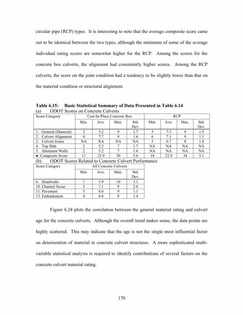
170
circular pipe (RCP) types. It is interesting to note that the average composite score came
out to be identical between the two types, although the minimum of some of the average
individual rating scores are somewhat higher for the RCP. Among the scores for the
concrete box culverts, the alignment had consistently higher scores. Among the RCP
culverts, the score on the joint condition had a tendency to be slightly lower than that on
the material condition or structural alignment.
Table 6.15: Basic Statistical Summary of Data Presented in Table 6.14 (a) ODOT Scores on Concrete Culverts
Cast-In-Place Concrete Box RCP Score Category Min. Ave. Max. Std.
Dev. Min. Ave. Max. Std.
Dev. 1. General (Material) 2 5.2 9 1.7 5 7.3 9 1.5 2. Culvert Alignment 4 7.7 9 1.6 6 7.1 9 1.1 3. Culvert Joints NA NA NA NA 5 6.7 8 1.0 4. Top Slab 2 5.2 7 1.7 NA NA NA NA 5. Abutment Walls 2 5.2 7 1.6 NA NA NA NA
Composite Score 11 22.9 30 5.6 18 22.9 34 5.1 (b) ODOT Scores Related to Concrete Culvert Performance
All Concrete Culverts Score Category Min. Ave. Max. Std.
Dev. 6. Headwalls 1 5.9 10 3.1 10. Channel Scour 3 7.1 9 2.0 11. Pavement 5 8.0 9 1.1 13. Embankment 4 6.6 8 1.4
Figure 6.24 plots the correlation between the general material rating and culvert
age for the concrete culverts. Although the overall trend makes sense, the data points are
highly scattered. This may indicate that the age is not the single most influential factor
on deterioration of material in concrete culvert structures. A more sophisticated multi-
variable statistical analysis is required to identify contributions of several factors on the
concrete culvert material rating.
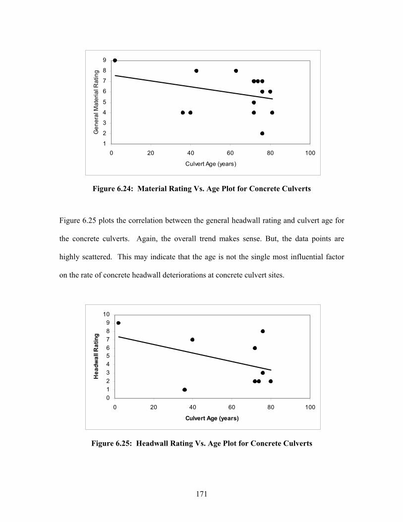
171
Figure 6.24: Material Rating Vs. Age Plot for Concrete Culverts
Figure 6.25 plots the correlation between the general headwall rating and culvert age for
the concrete culverts. Again, the overall trend makes sense. But, the data points are
highly scattered. This may indicate that the age is not the single most influential factor
on the rate of concrete headwall deteriorations at concrete culvert sites.
Figure 6.25: Headwall Rating Vs. Age Plot for Concrete Culverts
1
2
3
4
5
6
7
8
9
0 20 40 60 80 100
Culvert Age (years)
Gen
era
l Mat
eria
l Rat
ing
0123456789
10
0 20 40 60 80 100
Culvert Age (years)
Hea
dwal
l Rat
ing
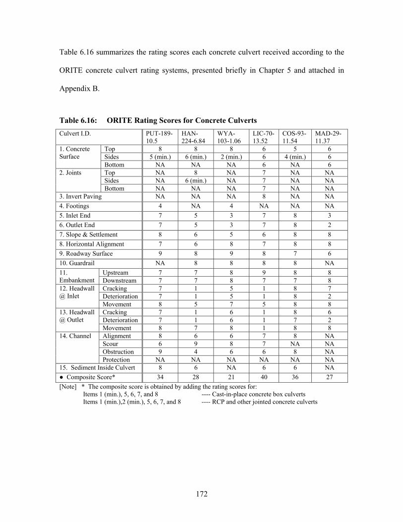
172
Table 6.16 summarizes the rating scores each concrete culvert received according to the
ORITE concrete culvert rating systems, presented briefly in Chapter 5 and attached in
Appendix B.
Table 6.16: ORITE Rating Scores for Concrete Culverts
Culvert I.D. PUT-189-10.5
HAN-224-6.84
WYA-103-1.06
LIC-70-13.52
COS-93-11.54
MAD-29-11.37
Top 8 8 8 6 5 6 Sides 5 (min.) 6 (min.) 2 (min.) 6 4 (min.) 6
1. Concrete Surface
Bottom NA NA NA 6 NA 6 Top NA 8 NA 7 NA NA Sides NA 6 (min.) NA 7 NA NA
2. Joints
Bottom NA NA NA 7 NA NA 3. Invert Paving NA NA NA 8 NA NA 4. Footings 4 NA 4 NA NA NA 5. Inlet End 7 5 3 7 8 3 6. Outlet End 7 5 3 7 8 2 7. Slope & Settlement 8 6 5 6 8 8 8. Horizontal Alignment 7 6 8 7 8 8 9. Roadway Surface 9 8 9 8 7 6 10. Guardrail NA 8 8 8 8 NA
Upstream 7 7 8 9 8 8 11. Embankment Downstream 7 7 8 7 7 8
Cracking 7 1 5 1 8 7 Deterioration 7 1 5 1 8 2
12. Headwall @ Inlet
Movement 8 5 7 5 8 8 Cracking 7 1 6 1 8 6 Deterioration 7 1 6 1 7 2
13. Headwall @ Outlet
Movement 8 7 8 1 8 8 Alignment 8 6 6 7 8 NA Scour 6 9 8 7 NA NA Obstruction 9 4 6 6 8 NA
14. Channel
Protection NA NA NA NA NA NA 15. Sediment Inside Culvert 8 6 NA 6 6 NA
Composite Score* 34 28 21 40 36 27 [Note] * The composite score is obtained by adding the rating scores for:
Items 1 (min.), 5, 6, 7, and 8 ---- Cast-in-place concrete box culverts Items 1 (min.),2 (min.), 5, 6, 7, and 8 ---- RCP and other jointed concrete culverts
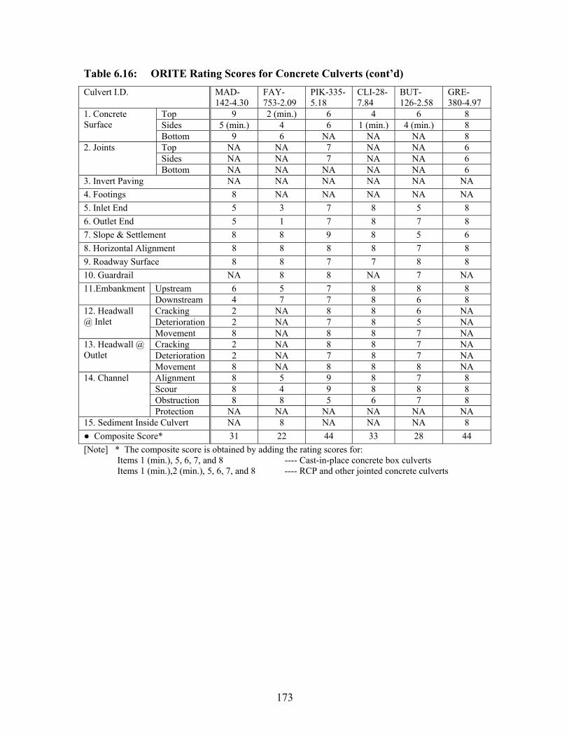
173
Table 6.16: ORITE Rating Scores for Concrete Culverts (cont’d)
Culvert I.D. MAD-142-4.30
FAY-753-2.09
PIK-335-5.18
CLI-28-7.84
BUT-126-2.58
GRE-380-4.97
Top 9 2 (min.) 6 4 6 8 Sides 5 (min.) 4 6 1 (min.) 4 (min.) 8
1. Concrete Surface
Bottom 9 6 NA NA NA 8 Top NA NA 7 NA NA 6 Sides NA NA 7 NA NA 6
2. Joints
Bottom NA NA NA NA NA 6 3. Invert Paving NA NA NA NA NA NA 4. Footings 8 NA NA NA NA NA 5. Inlet End 5 3 7 8 5 8 6. Outlet End 5 1 7 8 7 8 7. Slope & Settlement 8 8 9 8 5 6 8. Horizontal Alignment 8 8 8 8 7 8 9. Roadway Surface 8 8 7 7 8 8 10. Guardrail NA 8 8 NA 7 NA
Upstream 6 5 7 8 8 8 11.Embankment Downstream 4 7 7 8 6 8 Cracking 2 NA 8 8 6 NA Deterioration 2 NA 7 8 5 NA
12. Headwall @ Inlet
Movement 8 NA 8 8 7 NA Cracking 2 NA 8 8 7 NA Deterioration 2 NA 7 8 7 NA
13. Headwall @ Outlet
Movement 8 NA 8 8 8 NA Alignment 8 5 9 8 7 8 Scour 8 4 9 8 8 8 Obstruction 8 8 5 6 7 8
14. Channel
Protection NA NA NA NA NA NA 15. Sediment Inside Culvert NA 8 NA NA NA 8
Composite Score* 31 22 44 33 28 44 [Note] * The composite score is obtained by adding the rating scores for:
Items 1 (min.), 5, 6, 7, and 8 ---- Cast-in-place concrete box culverts Items 1 (min.),2 (min.), 5, 6, 7, and 8 ---- RCP and other jointed concrete culverts
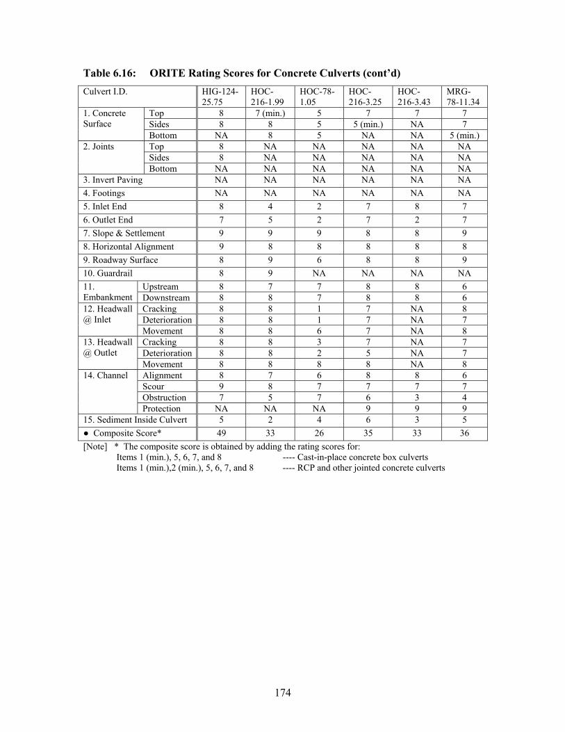
174
Table 6.16: ORITE Rating Scores for Concrete Culverts (cont’d)
Culvert I.D. HIG-124-25.75
HOC-216-1.99
HOC-78-1.05
HOC-216-3.25
HOC-216-3.43
MRG-78-11.34
Top 8 7 (min.) 5 7 7 7 Sides 8 8 5 5 (min.) NA 7
1. Concrete Surface
Bottom NA 8 5 NA NA 5 (min.) Top 8 NA NA NA NA NA Sides 8 NA NA NA NA NA
2. Joints
Bottom NA NA NA NA NA NA 3. Invert Paving NA NA NA NA NA NA 4. Footings NA NA NA NA NA NA 5. Inlet End 8 4 2 7 8 7 6. Outlet End 7 5 2 7 2 7 7. Slope & Settlement 9 9 9 8 8 9 8. Horizontal Alignment 9 8 8 8 8 8 9. Roadway Surface 8 9 6 8 8 9 10. Guardrail 8 9 NA NA NA NA
Upstream 8 7 7 8 8 6 11. Embankment Downstream 8 8 7 8 8 6
Cracking 8 8 1 7 NA 8 Deterioration 8 8 1 7 NA 7
12. Headwall @ Inlet
Movement 8 8 6 7 NA 8 Cracking 8 8 3 7 NA 7 Deterioration 8 8 2 5 NA 7
13. Headwall @ Outlet
Movement 8 8 8 8 NA 8 Alignment 8 7 6 8 8 6 Scour 9 8 7 7 7 7 Obstruction 7 5 7 6 3 4
14. Channel
Protection NA NA NA 9 9 9 15. Sediment Inside Culvert 5 2 4 6 3 5
Composite Score* 49 33 26 35 33 36 [Note] * The composite score is obtained by adding the rating scores for:
Items 1 (min.), 5, 6, 7, and 8 ---- Cast-in-place concrete box culverts Items 1 (min.),2 (min.), 5, 6, 7, and 8 ---- RCP and other jointed concrete culverts

175
Table 6.16: ORITE Rating Scores for Concrete Culverts (cont’d)
Culvert I.D. MRG-78-24.97
VIN-56-6.85
MEG-338-16.42
ATH-278-0.25
MRG-60-19.95
CUY-480-0.75
CUY-422-15.2
Top 4 (min.) 7 2 (min.) 9 7 6 (min.) 8 Sides 4 (min.) 6 (min.) 2 (min.) 9 7 6 (min.) 8
1. Concrete Surface
Bottom 5 6 (min.) NA NA 7 7 8 Top NA NA NA 7 NA 7 8 Sides NA NA NA 7 NA 7 6 (min.)
2. Joints
Bottom NA NA NA NA NA 7 8 3. Invert Paving NA NA NA NA NA NA NA 4. Footings NA NA NA NA NA NA NA 5. Inlet End 7 3 8 9 4 7 8 6. Outlet End 2 3 8 9 7 4 8 7. Slope & Settlement 7 9 4 7 9 8 7 8. Horizontal Alignment 8 8 8 8 9 8 8 9. Roadway Surface 8 9 7 9 5 UC 9 10. Guardrail NA NA NA NA 8 NA NA
Upstream 5 4 4 6 3 8 8 11. Embankment Downstream 4 9 3 6 5 8 8
Cracking 7 2 8 9 1 7 8 Deterioration 6 4 8 9 1 7 8
12. Headwall @ Inlet
Movement 7 6 8 9 8 8 8 Cracking 1 2 8 9 7 8 8 Deterioration 1 3 8 9 7 8 8
13. Headwall @ Outlet
Movement 6 6 8 9 8 8 8 Alignment 6 6 4 7 6 8 8 Scour 4 8 6 9 8 9 9 Obstruction 4 4 8 6 8 8 6
14. Channel
Protection NA NA NA NA NA 8 NA 15. Sediment Inside Culvert 3 6 NA 6 9 6 4
Composite Score* 28 29 30 49 36 40 45 [Note] * The composite score is obtained by adding the rating scores for:
Items 1 (min.), 5, 6, 7, and 8 ---- Cast-in-place concrete box culverts Items 1 (min.),2 (min.), 5, 6, 7, and 8 ---- RCP and other jointed concrete culverts
Results of a basic statistical analysis performed on the key ORITE rating scores
are presented in Table 6.17 for the box and circular pipe (RCP) types. The average
concrete surface rating scores established for three different regions (top, sides, invert),
show that concrete material deteriorations are a more concern for the sides and invert
than for the top/crown. Statistical results are very similar between the inlet and outlet
ends. Statistical results are also similar between the inlet headwall and outlet headwall.

176
The headwall movement is not a concern at the concrete culvert sites. Table 6.17
confirms that horizontal and vertical alignment problems are generally rare for concrete
culvert structures. Finally, the rating scores are very similar for common items between
Tables 6.15 and 6.17. This provides validity to the ODOT culvert rating systems, which
have lower-resolution than the ORITE rating systems.
Table 6.17: Basic Statistical Summary of Data Presented in Table 6.16 (a) ORITE Scores Related to Concrete Culvert
Cast-In-Place Concrete Box RCP Score Category Min. Ave. Max. Std.
Dev. Min. Ave. Max. Std.
Dev. Top 2 5.7 9 2.0 6 7.6 9 1.0 Sides 1 4.8 8 1.8 6 7.3 9 1.2
1. Concrete Surface
Invert 5 6.3* 9 1.3 7 7.3 8 0.8 Top NA NA NA NA 6 7.3 8 0.8 Sides NA NA NA NA 6 6.7 8 0.7
2. Culvert Joints
Invert NA NA NA NA 6 7.0 8 0.7 5. Inlet End 2 5.5 8 2.1 7 7.4 9 1.2 6. Outlet End 1 5.1 8 2.5 4 6.9 9 1.6 7. Slope & Settlement 4 7.7 9 1.5 6 7.0 9 1.1 8. Horiz. Alignment 6 7.9 9 0.4 7 7.7 9 0.9
Composite Score 21 31.2 36 5.4 40 42.1 49 6.7 * [Note] The average score is skewed due to a lack of data points.
(b) ORITE Scores Related to Concrete Culvert Performance All Concrete Culverts Score Category
Min. Ave. Max. Std. Dev.
9. Roadway Surface 5 7.8 9 1.1 Upstream 3 6.8 9 1.6 11.
Embankment Downstream 3 6.9 9 1.5 Cracking 1 5.8 9 2.8 Deterioration 1 5.5 9 2.8
12. Headwall @ Inlet
Movement 5 7.4 9 1.1 Cracking 1 5.9 9 2.7 Deterioration 1 5.5 9 2.8
13. Headwall @ Outlet
Movement 1 7.5 9 1.6 Alignment 4 7.0 8 1.2 Scour 4 7.5 9 1.4
14. Channel
Obstruction 3 6.3 9 1.6 15. Sediment Inside Culvert 2 5.6 9 1.9

177
6.3.2 Basic Analysis of Data Collected at Metal Culvert Sites
No stress cracks were found at the bolt lines inside any of the metal culverts.
Table 6.18 summarizes the rating scores each metal culvert received according to the
metal culvert rating system presented in the ODOT Culvert Management Manual (ODOT,
2003).
Table 6.18: ODOT Rating Scores for Metal Culverts
Culvert I.D. PAU-66-2.44
DEF-18-20.60
PUT-15-14.78
LIC-16-13.66
GUE-70-8.94
MUS-93-1.76
1. General (Material) 6 7 6 5 5 5 2. Culvert Alignment 8 7 6 6 9 6 3. Culvert Shape 5 4 6 7 3 4 4. Seams/Joints 7 8 8 7 8 6 5. Headwalls NA NA 4 4 9 2 6. Channel Alignment 7 8 8 4 8 5 7. Channel Protection NA NA NA NA NA 6 8. Waterway Blockage 7 6 5 7 7 5 9. Channel Scour 8 8 3 4 8 5 10. Pavement 8 8 8 9 8 8 11. Guardrail NA NA 8 8 8 8 12. Embankment 8 7 8 5 7 7
Composite Score* 26 26 26 25 25 21
Culvert I.D. GUE-77-7.85R
KNO-95-0.08
MAD-29-8.80
CLI-124-0.03
HIG-50-19.82
JAC-124-17.12
1. General (Material) 5 4 4 4 6 7 2. Culvert Alignment 8 6 6 7 8 7 3. Culvert Shape 6 3 6 7 7 5 4. Seams/Joints 7 4 7 6 7 7 5. Headwalls 7 NA 3 8 NA 0 6. Channel Alignment 7 NF 8 8 8 6 7. Channel Protection 5 NA NA 8 8 NA 8. Waterway Blockage 7 NA 8 8 7 5 9. Channel Scour 8 NA 4 6 8 5 10. Pavement 7 8 5 8 6 5 11. Guardrail 8 NA 5 9 7 8 12. Embankment 8 7 4 7 8 8
Composite Score* 26 17 23 24 28 26

178
Table 6.18: ODOT Rating Scores for Metal Culverts (cont’d)
Culvert I.D. PIK-32-15.96
ADA-247-11.87
HOC-595-2.85
HOC-664-17.16
HOC-664-22.40
GAL-7-21.30
1. General (Material) 9 6 4 6 4 2 2. Culvert Alignment 8 6 8 8 3 3 3. Culvert Shape 6 6 7 8 3 7 4. Seams/Joints 7 7 7 8 2 2 5. Headwalls 8 NA 1 3 0 6 6. Channel Alignment 7 6 3 8 8 2 7. Channel Protection 8 NA NA NA NA 6 8. Waterway Blockage 9 6 8 7 6 8 9. Channel Scour 3 NA 0 6 4 6 10. Pavement 8 7 7 3 6 3 11. Guardrail 8 8 NA NA 8 7 12. Embankment 6 8 4 6 6 3
Composite Score* 30 25 26 30 12 14
Culvert I.D. MEG-681-7.94
MEG-681-13.96
HOC-595-4.57
WAS-339-15.25
WAS-60-4.84
LAK-90-14.00
LAK-90-4.20
1. General (Material) 6 5 2 4 5 8 7 2. Culvert Alignment 8 8 7 6 8 9 6 3. Culvert Shape 5 8 6 8 5 8 8 4. Seams/Joints 7 7 8 8 5 8 8 5. Headwalls 2 8 4 6 4 4 6 6. Channel Alignment 5 6 4 8 8 9 6 7. Channel Protection NA NA NA NA 8 NA NA 8. Waterway Blockage 4 5 7 8 8 8 7 9. Channel Scour 5 6 5 6 9 4 4 10. Pavement 8 8 6 7 8 9 8 11. Guardrail 8 8 NA 6 8 9 8 12. Embankment 7 7 6 7 5 6 7
Composite Score* 26 28 23 26 23 33 29 [Note] * Composite Score is obtained by adding the rating scores for Items 1 through 4.
Results of a basic statistical analysis performed on the key ODOT rating scores
are presented in Table 6.19 for the metal culverts. The average rating score was the
lowest on the general material conditions. The second lowest average rating score was
related to the shape. The highest average rating score was associated with the culvert
alignment. The standard deviation of the rating scores was very similar among the four

179
key performance categories. The average composite score among the metal culverts
came out to be slightly better than the average composite score among the concrete
culverts (refer to Table 6.17).
Table 6.19: Basic Statistical Summary of Data Presented in Table 6.18 (a) ODOT Scores on Metal Culverts
Metal Culverts: Score Category Min. Ave. Max. Std. Dev.
1. General (Material) 2 5.3 9 1.6 2. Culvert Alignment 3 6.9 9 1.5 3. Culvert Shape 3 5.9 8 1.6 4. Seams/Joints 2 6.6 8 1.7
Composite Score 12 24.7 33 4.6 (b) ODOT Scores Related to Metal Culvert Performance
Metal Culverts: Score Category Min. Ave. Max. Std. Dev.
5. Headwalls 0 4.5 9 2.7 9. Channel Scour 0 5.4 9 2.1 10. Pavement 3 7.0 9 1.6 12. Embankment 3 6.5 8 1.4
Figure 6.26 plots the correlation between the general material rating and culvert
age for the metal culverts. Although the overall trend is as expected, there is a
considerable degree of scattering in the data point distribution especially for the age of 40
to 50 years. This may indicate that the age is not the single most influential factor on
deterioration of material in metal culvert structures. A more sophisticated multi-variable
statistical analysis is required to identify contributions of several factors on the metal
culvert material rating. The plot indicates that the service life of metal culverts may be
limited to less than 70 years in Ohio.
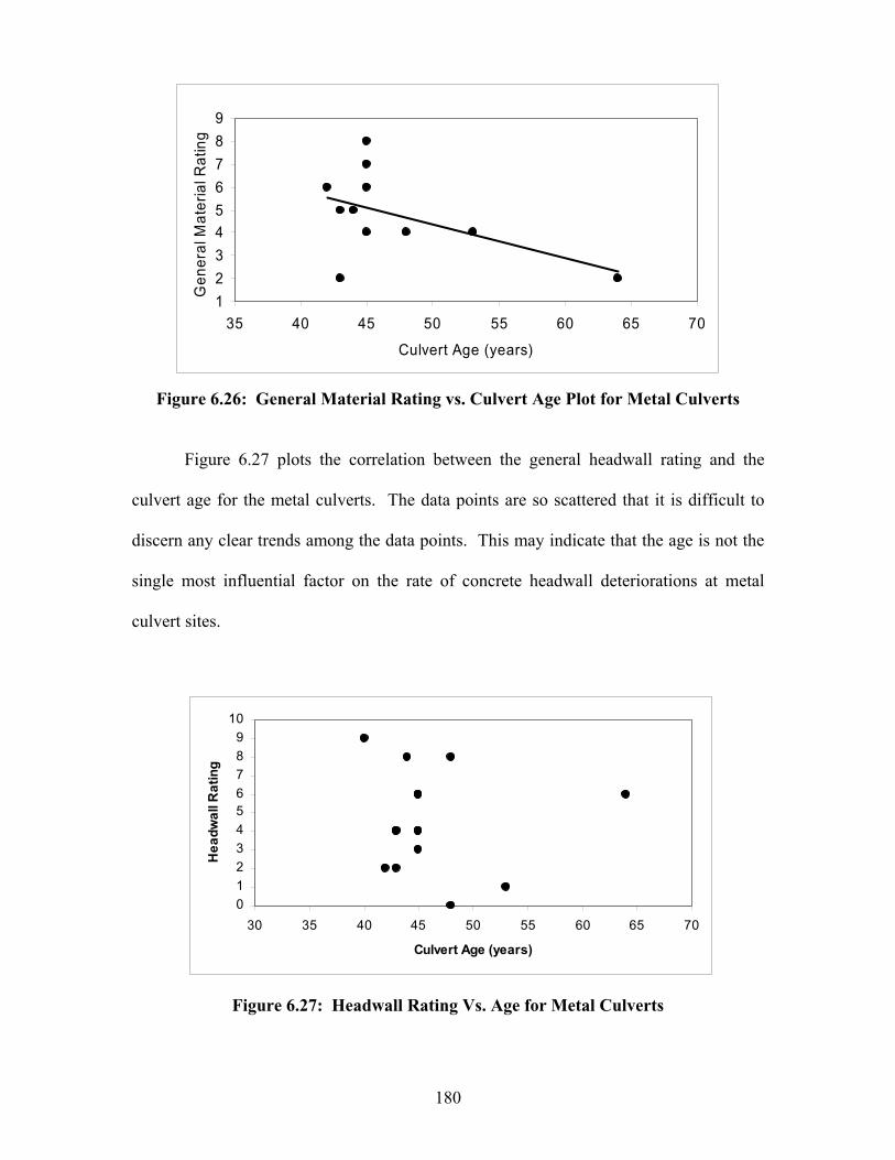
180
Figure 6.26: General Material Rating vs. Culvert Age Plot for Metal Culverts
Figure 6.27 plots the correlation between the general headwall rating and the
culvert age for the metal culverts. The data points are so scattered that it is difficult to
discern any clear trends among the data points. This may indicate that the age is not the
single most influential factor on the rate of concrete headwall deteriorations at metal
culvert sites.
Figure 6.27: Headwall Rating Vs. Age for Metal Culverts
1
2
3
45
6
7
8
9
35 40 45 50 55 60 65 70
Culvert Age (years)
Gen
eral
Mat
eria
l Rat
ing
0123456789
10
30 35 40 45 50 55 60 65 70
Culvert Age (years)
Hea
dwal
l Rat
ing
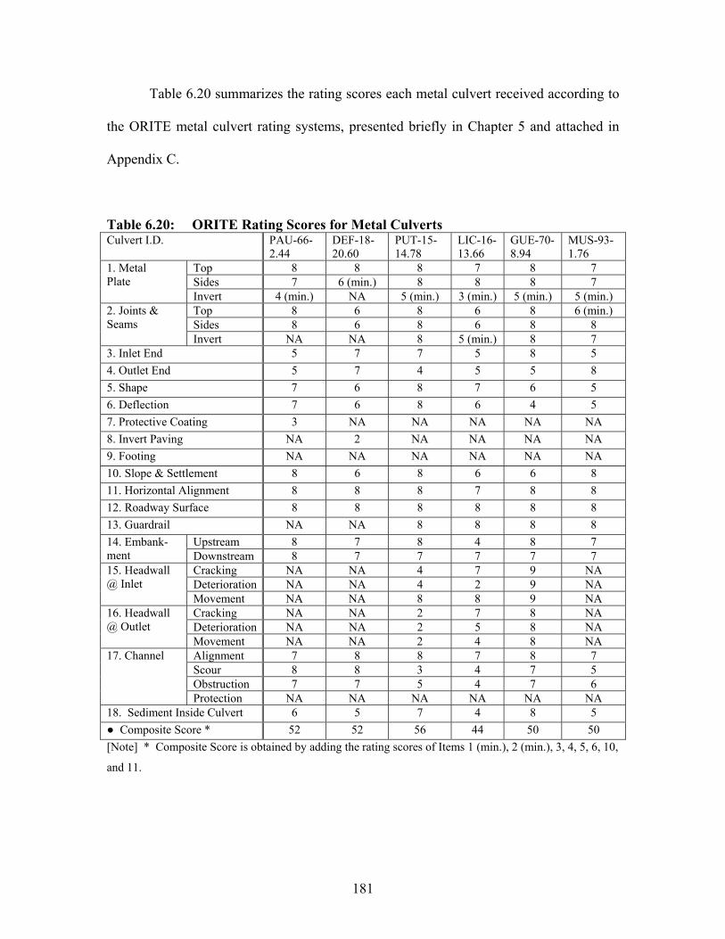
181
Table 6.20 summarizes the rating scores each metal culvert received according to
the ORITE metal culvert rating systems, presented briefly in Chapter 5 and attached in
Appendix C.
Table 6.20: ORITE Rating Scores for Metal Culverts Culvert I.D. PAU-66-
2.44 DEF-18-20.60
PUT-15-14.78
LIC-16-13.66
GUE-70-8.94
MUS-93-1.76
Top 8 8 8 7 8 7 Sides 7 6 (min.) 8 8 8 7
1. Metal Plate
Invert 4 (min.) NA 5 (min.) 3 (min.) 5 (min.) 5 (min.) Top 8 6 8 6 8 6 (min.) Sides 8 6 8 6 8 8
2. Joints & Seams
Invert NA NA 8 5 (min.) 8 7 3. Inlet End 5 7 7 5 8 5 4. Outlet End 5 7 4 5 5 8 5. Shape 7 6 8 7 6 5 6. Deflection 7 6 8 6 4 5 7. Protective Coating 3 NA NA NA NA NA 8. Invert Paving NA 2 NA NA NA NA 9. Footing NA NA NA NA NA NA 10. Slope & Settlement 8 6 8 6 6 8 11. Horizontal Alignment 8 8 8 7 8 8 12. Roadway Surface 8 8 8 8 8 8 13. Guardrail NA NA 8 8 8 8
Upstream 8 7 8 4 8 7 14. Embank-ment Downstream 8 7 7 7 7 7
Cracking NA NA 4 7 9 NA Deterioration NA NA 4 2 9 NA
15. Headwall @ Inlet
Movement NA NA 8 8 9 NA Cracking NA NA 2 7 8 NA Deterioration NA NA 2 5 8 NA
16. Headwall @ Outlet
Movement NA NA 2 4 8 NA Alignment 7 8 8 7 8 7 Scour 8 8 3 4 7 5 Obstruction 7 7 5 4 7 6
17. Channel
Protection NA NA NA NA NA NA 18. Sediment Inside Culvert 6 5 7 4 8 5
Composite Score * 52 52 56 44 50 50 [Note] * Composite Score is obtained by adding the rating scores of Items 1 (min.), 2 (min.), 3, 4, 5, 6, 10,
and 11.
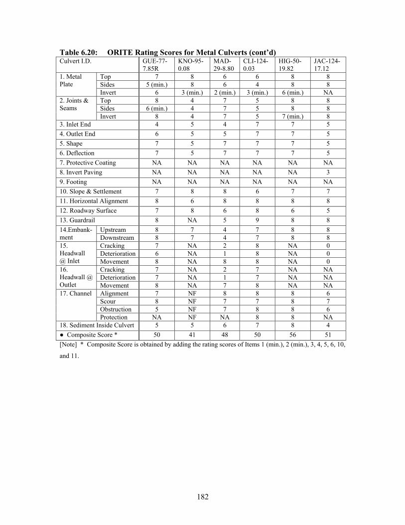
182
Table 6.20: ORITE Rating Scores for Metal Culverts (cont’d) Culvert I.D. GUE-77-
7.85R KNO-95-0.08
MAD-29-8.80
CLI-124-0.03
HIG-50-19.82
JAC-124-17.12
Top 7 8 6 6 8 8 Sides 5 (min.) 8 6 4 8 8
1. Metal Plate
Invert 6 3 (min.) 2 (min.) 3 (min.) 6 (min.) NA Top 8 4 7 5 8 8 Sides 6 (min.) 4 7 5 8 8
2. Joints & Seams
Invert 8 4 7 5 7 (min.) 8 3. Inlet End 4 5 4 7 7 5 4. Outlet End 6 5 5 7 7 5 5. Shape 7 5 7 7 7 5 6. Deflection 7 5 7 7 7 5 7. Protective Coating NA NA NA NA NA NA 8. Invert Paving NA NA NA NA NA 3 9. Footing NA NA NA NA NA NA 10. Slope & Settlement 7 8 8 6 7 7 11. Horizontal Alignment 8 6 8 8 8 8 12. Roadway Surface 7 8 6 8 6 5 13. Guardrail 8 NA 5 9 8 8
Upstream 8 7 4 7 8 8 14.Embank-ment Downstream 8 7 4 7 8 8
Cracking 7 NA 2 8 NA 0 Deterioration 6 NA 1 8 NA 0
15. Headwall@ Inlet Movement 8 NA 8 8 NA 0
Cracking 7 NA 2 7 NA NA Deterioration 7 NA 1 7 NA NA
16. Headwall @ Outlet Movement 8 NA 7 8 NA NA
Alignment 7 NF 8 8 8 6 Scour 8 NF 7 7 8 7 Obstruction 5 NF 7 8 8 6
17. Channel
Protection NA NF NA 8 8 NA 18. Sediment Inside Culvert 5 5 6 7 8 4
Composite Score * 50 41 48 50 56 51 [Note] * Composite Score is obtained by adding the rating scores of Items 1 (min.), 2 (min.), 3, 4, 5, 6, 10,
and 11.

183
Table 6.20: ORITE Rating Scores for Metal Culverts (cont’d) Culvert I.D. PIK-32-
15.96 ADA-247-11.87
HOC-595-2.85
HOC-664-17.16
HOC-664-22.40
GAL-7-21.30
Top 9 6 7 8 7 7 Sides 9 7 7 6 (min.) 7 7
1. Metal Plate
Invert 9 6 2 (min.) NA 3 (min.) 1 (min.) Top 7 7 8 8 8 1 Sides 7 5 (min.) 8 8 8 1
2. Joints & Seams
Invert 7 NA 7 (min.) NA 1 (min.) 1 3. Inlet End 9 8 3 4 1 3 4. Outlet End 3 8 2 5 3 2 5. Shape 8 7 7 7 2 NA 6. Deflection 8 7 7 7 5 NA 7. Protective Coating NA NA NA NA 7 2 8. Invert Paving 8 NA NA NA NA NA 9. Footing NA NA NA NA NA NA 10. Slope & Settlement 8 8 7 7 3 2 11. Horizontal Alignment 7 8 8 8 3 2 12. Roadway Surface 8 7 6 4 5 1 13. Guardrail 8 8 NA NA 8 7
Upstream 9 8 4 6 7 8 14.Embank-ment Downstream 6 8 4 8 7 2
Cracking 9 NA 2 3 0 7 Deterioration 9 NA 2 3 0 7
15. Headwall @ Inlet
Movement 9 NA 2 3 0 7 Cracking 9 NA 1 2 3 NA Deterioration 9 NA 1 2 3 NA
16. Headwall @ Outlet
Movement 9 NA 1 2 3 NA Alignment 7 6 NA 8 8 8 Scour 3 8 NA 7 6 5 Obstruction 9 6 NA 7 6 6
17. Channel
Protection 8 NA NA NA NA NA 18. Sediment Inside Culvert 9 8 7 4 4 8
Composite Score * 59 57 43 52 21 11 [Note] * Composite Score is obtained by adding the rating scores of Items 1 (min.), 2 (min.), 3, 4, 5, 6, 10,
and 11.
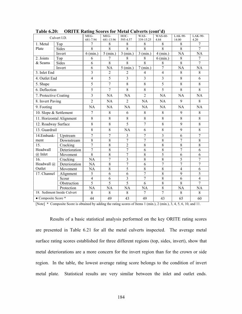
184
Table 6.20: ORITE Rating Scores for Metal Culverts (cont’d) Culvert I.D. MEG-
681-7.94 MEG-681-13.96
HOC-595-4.57
WAS-339-15.25
WAS-60-4.84
LAK-90-14.00
LAK-90-4.20
Top 7 8 8 8 8 8 7 Sides 8 8 8 8 8 8 7
1. Metal Plate
Invert 6 (min.) 5 (min.) 3 (min.) 3 (min.) 4 (min.) NA NA Top 6 7 8 8 6 (min.) 8 7 Sides 6 8 8 8 8 8 7
2. Joints & Seams
Invert 6 NA 5 (min.) 7 (min.) 7 NA NA 3. Inlet End 3 2 2 4 4 8 8 4. Outlet End 4 5 3 3 3 8 6 5. Shape 5 7 8 8 5 8 8 6. Deflection 5 7 8 8 5 8 8 7. Protective Coating 3 NA NA 2 NA NA NA 8. Invert Paving 2 NA 2 NA NA 9 8 9. Footing NA NA NA NA NA NA NA 10. Slope & Settlement 7 8 6 8 8 9 8 11. Horizontal Alignment 8 8 8 8 8 8 8 12. Roadway Surface 8 8 5 7 8 9 8 13. Guardrail 8 8 NA 6 8 9 8
Upstream 7 7 3 7 3 6 7 14.Embank-ment Downstream 8 8 7 7 8 7 8
Cracking 7 8 2 8 8 8 8 Deterioration 7 8 7 6 8 7 6
15. Headwall@ Inlet Movement 8 8 7 8 5 6 6
Cracking NA 7 3 8 8 5 7 Deterioration NA 8 7 6 7 7 7
16. Headwall @ Outlet Movement NA 8 5 8 8 4 6
Alignment 5 6 6 7 8 9 5 Scour 4 6 3 7 8 6 4 Obstruction 5 5 5 6 8 8 7
17. Channel
Protection NA NA NA NA 8 NA NA 18. Sediment Inside Culvert 8 8 8 7 7 8 8
Composite Score * 44 49 43 49 43 65 60 [Note] * Composite Score is obtained by adding the rating scores of Items 1 (min.), 2 (min.), 3, 4, 5, 6, 10, and 11.
Results of a basic statistical analysis performed on the key ORITE rating scores
are presented in Table 6.21 for all the metal culverts inspected. The average metal
surface rating scores established for three different regions (top, sides, invert), show that
metal deteriorations are a more concern for the invert region than for the crown or side
region. In the table, the lowest average rating score belongs to the condition of invert
metal plate. Statistical results are very similar between the inlet and outlet ends.
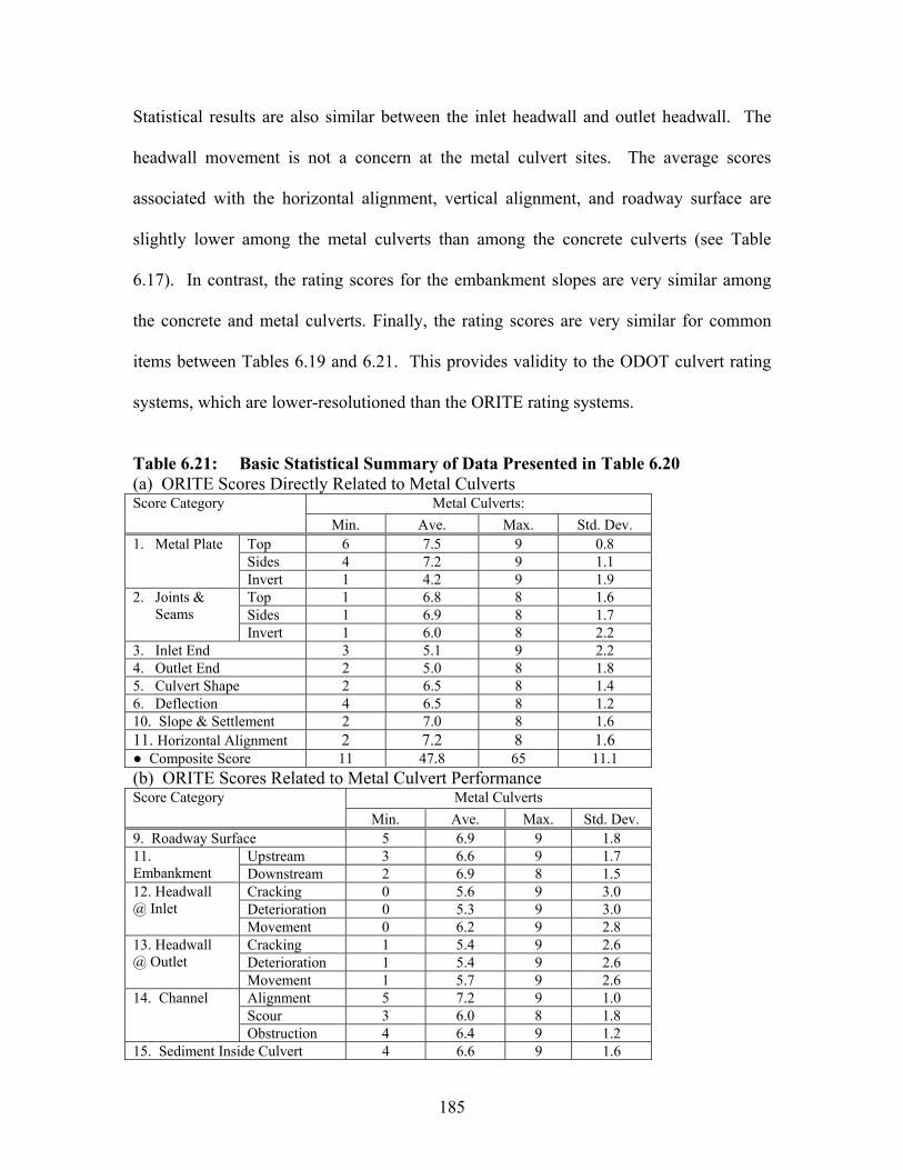
185
Statistical results are also similar between the inlet headwall and outlet headwall. The
headwall movement is not a concern at the metal culvert sites. The average scores
associated with the horizontal alignment, vertical alignment, and roadway surface are
slightly lower among the metal culverts than among the concrete culverts (see Table
6.17). In contrast, the rating scores for the embankment slopes are very similar among
the concrete and metal culverts. Finally, the rating scores are very similar for common
items between Tables 6.19 and 6.21. This provides validity to the ODOT culvert rating
systems, which are lower-resolutioned than the ORITE rating systems.
Table 6.21: Basic Statistical Summary of Data Presented in Table 6.20 (a) ORITE Scores Directly Related to Metal Culverts
Metal Culverts: Score Category Min. Ave. Max. Std. Dev.
Top 6 7.5 9 0.8 Sides 4 7.2 9 1.1
1. Metal Plate
Invert 1 4.2 9 1.9 Top 1 6.8 8 1.6 Sides 1 6.9 8 1.7
2. Joints & Seams
Invert 1 6.0 8 2.2 3. Inlet End 3 5.1 9 2.2 4. Outlet End 2 5.0 8 1.8 5. Culvert Shape 2 6.5 8 1.4 6. Deflection 4 6.5 8 1.2 10. Slope & Settlement 2 7.0 8 1.6 11. Horizontal Alignment 2 7.2 8 1.6
Composite Score 11 47.8 65 11.1 (b) ORITE Scores Related to Metal Culvert Performance
Metal Culverts Score Category Min. Ave. Max. Std. Dev.
9. Roadway Surface 5 6.9 9 1.8 Upstream 3 6.6 9 1.7 11.
Embankment Downstream 2 6.9 8 1.5 Cracking 0 5.6 9 3.0 Deterioration 0 5.3 9 3.0
12. Headwall @ Inlet
Movement 0 6.2 9 2.8 Cracking 1 5.4 9 2.6 Deterioration 1 5.4 9 2.6
13. Headwall @ Outlet
Movement 1 5.7 9 2.6 Alignment 5 7.2 9 1.0 Scour 3 6.0 8 1.8
14. Channel
Obstruction 4 6.4 9 1.2 15. Sediment Inside Culvert 4 6.6 9 1.6
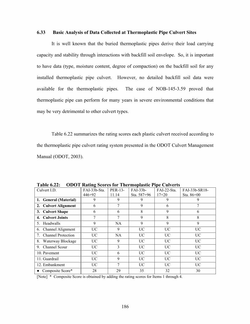
186
6.33 Basic Analysis of Data Collected at Thermoplastic Pipe Culvert Sites
It is well known that the buried thermoplastic pipes derive their load carrying
capacity and stability through interactions with backfill soil envelope. So, it is important
to have data (type, moisture content, degree of compaction) on the backfill soil for any
installed thermoplastic pipe culvert. However, no detailed backfill soil data were
available for the thermoplastic pipes. The case of NOB-145-3.59 proved that
thermoplastic pipe can perform for many years in severe environmental conditions that
may be very detrimental to other culvert types.
Table 6.22 summarizes the rating scores each plastic culvert received according to
the thermoplastic pipe culvert rating system presented in the ODOT Culvert Management
Manual (ODOT, 2003).
Table 6.22: ODOT Rating Scores for Thermoplastic Pipe Culverts Culvert I.D. FAI-33b-Sta.
446+92 PER-13-11.14
FAI-33b-Sta. 587+96
FAI-22-Sta. 17+20
FAI-33b-SR18-Sta. 86+00
1. General (Material) 9 9 9 9 9 2. Culvert Alignment 6 7 9 6 7 3. Culvert Shape 6 6 8 9 6 4. Culvert Joints 7 7 9 8 8 5. Headwalls 9 NA 9 9 9 6. Channel Alignment UC 9 UC UC UC 7. Channel Protection UC NA UC UC UC 8. Waterway Blockage UC 9 UC UC UC 9. Channel Scour UC 3 UC UC UC 10. Pavement UC 6 UC UC UC 11. Guardrail UC 9 UC UC UC 12. Embankment UC 7 UC UC UC
Composite Score* 28 29 35 32 30 [Note] * Composite Score is obtained by adding the rating scores for Items 1 through 4.
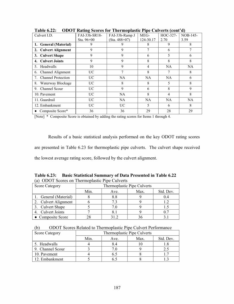
187
Table 6.22: ODOT Rating Scores for Thermoplastic Pipe Culverts (cont’d) Culvert I.D. FAI-33b-SR18-
Sta. 96+00 FAI-33b-Ramp J (Sta. 488+07)
MEG-124-30.17
HOC-327-2.70
NOB-145-3.59
1. General (Material) 9 9 8 9 8 2. Culvert Alignment 9 9 7 6 7 3. Culvert Shape 9 9 6 5 6 4. Culvert Joints 9 9 8 8 8 5. Headwalls 10 9 4 NA NA 6. Channel Alignment UC 7 8 7 8 7. Channel Protection UC NA NA NA 6 8. Waterway Blockage UC 8 8 5 8 9. Channel Scour UC 9 6 8 9 10. Pavement UC NA 8 4 8 11. Guardrail UC NA NA NA NA 12. Embankment UC UC 5 6 8
Composite Score* 36 36 29 28 29 [Note] * Composite Score is obtained by adding the rating scores for Items 1 through 4.
Results of a basic statistical analysis performed on the key ODOT rating scores
are presented in Table 6.23 for thermoplastic pipe culverts. The culvert shape received
the lowest average rating score, followed by the culvert alignment.
Table 6.23: Basic Statistical Summary of Data Presented in Table 6.22 (a) ODOT Scores on Thermoplastic Pipe Culverts
Thermoplastic Pipe Culverts Score Category Min. Ave. Max. Std. Dev.
1. General (Material) 8 8.8 9 0.4 2. Culvert Alignment 6 7.3 9 1.2 3. Culvert Shape 5 7.0 9 1.5 4. Culvert Joints 7 8.1 9 0.7
Composite Score 28 31.2 36 3.1
(b) ODOT Scores Related to Thermoplastic Pipe Culvert Performance Thermoplastic Pipe Culverts Score Category
Min. Ave. Max. Std. Dev. 5. Headwalls 4 8.4 10 1.8 9. Channel Scour 3 7.0 9 2.5 10. Pavement 4 6.5 8 1.7 12. Embankment 5 6.5 8 1.3
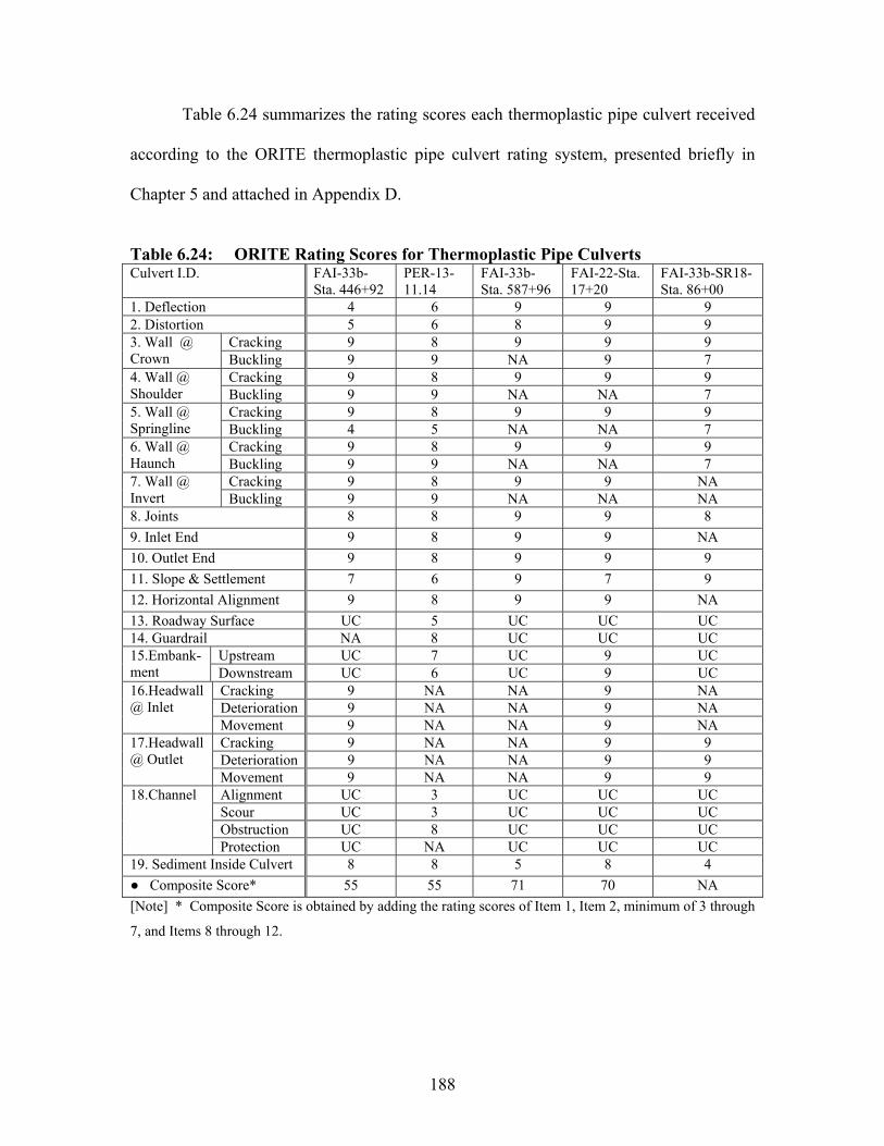
188
Table 6.24 summarizes the rating scores each thermoplastic pipe culvert received
according to the ORITE thermoplastic pipe culvert rating system, presented briefly in
Chapter 5 and attached in Appendix D.
Table 6.24: ORITE Rating Scores for Thermoplastic Pipe Culverts Culvert I.D. FAI-33b-
Sta. 446+92 PER-13-11.14
FAI-33b-Sta. 587+96
FAI-22-Sta. 17+20
FAI-33b-SR18-Sta. 86+00
1. Deflection 4 6 9 9 9 2. Distortion 5 6 8 9 9
Cracking 9 8 9 9 9 3. Wall @ Crown Buckling 9 9 NA 9 7
Cracking 9 8 9 9 9 4. Wall @ Shoulder Buckling 9 9 NA NA 7
Cracking 9 8 9 9 9 5. Wall @ Springline Buckling 4 5 NA NA 7
Cracking 9 8 9 9 9 6. Wall @ Haunch Buckling 9 9 NA NA 7
Cracking 9 8 9 9 NA 7. Wall @ Invert Buckling 9 9 NA NA NA 8. Joints 8 8 9 9 8 9. Inlet End 9 8 9 9 NA 10. Outlet End 9 8 9 9 9 11. Slope & Settlement 7 6 9 7 9 12. Horizontal Alignment 9 8 9 9 NA 13. Roadway Surface UC 5 UC UC UC 14. Guardrail NA 8 UC UC UC
Upstream UC 7 UC 9 UC 15.Embank-ment Downstream UC 6 UC 9 UC
Cracking 9 NA NA 9 NA Deterioration 9 NA NA 9 NA
16.Headwall @ Inlet
Movement 9 NA NA 9 NA Cracking 9 NA NA 9 9 Deterioration 9 NA NA 9 9
17.Headwall @ Outlet
Movement 9 NA NA 9 9 Alignment UC 3 UC UC UC Scour UC 3 UC UC UC Obstruction UC 8 UC UC UC
18.Channel
Protection UC NA UC UC UC 19. Sediment Inside Culvert 8 8 5 8 4
Composite Score* 55 55 71 70 NA [Note] * Composite Score is obtained by adding the rating scores of Item 1, Item 2, minimum of 3 through
7, and Items 8 through 12.
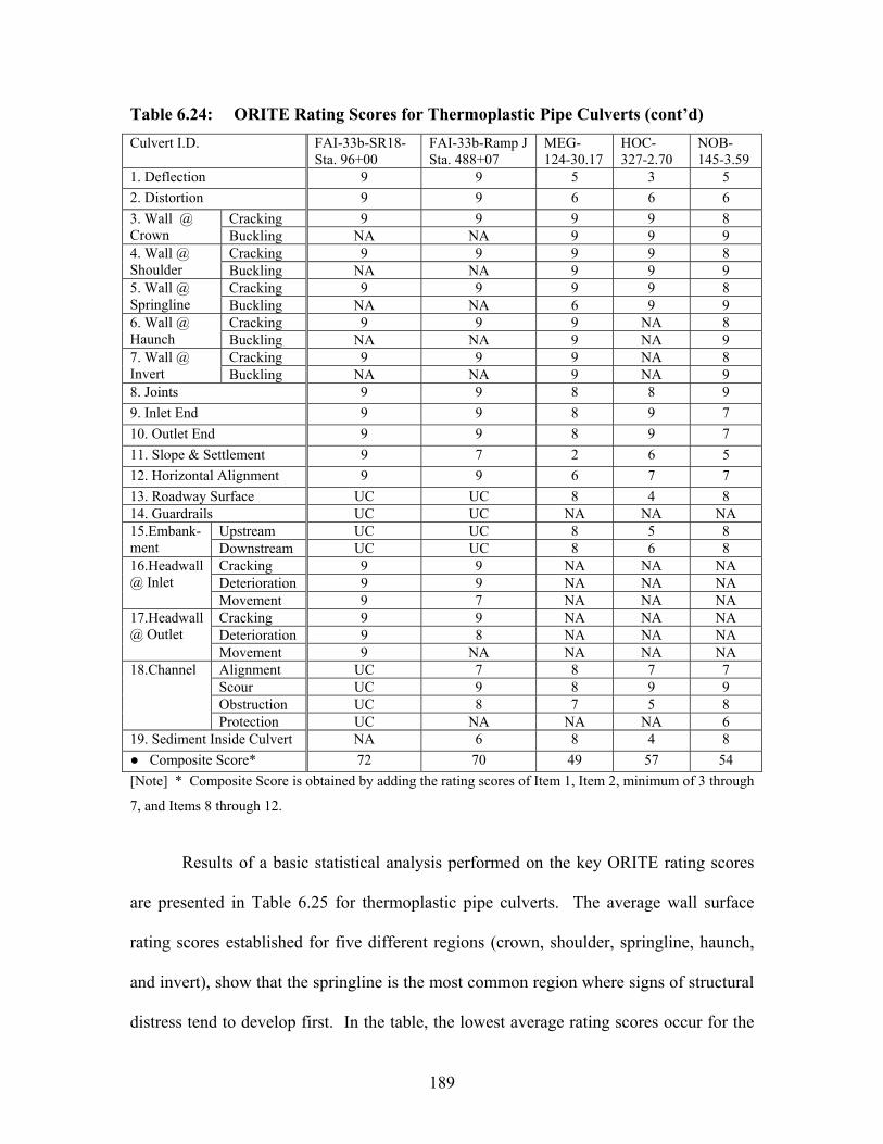
189
Table 6.24: ORITE Rating Scores for Thermoplastic Pipe Culverts (cont’d)
Culvert I.D. FAI-33b-SR18-Sta. 96+00
FAI-33b-Ramp J Sta. 488+07
MEG-124-30.17
HOC-327-2.70
NOB-145-3.59
1. Deflection 9 9 5 3 5 2. Distortion 9 9 6 6 6
Cracking 9 9 9 9 8 3. Wall @ Crown Buckling NA NA 9 9 9
Cracking 9 9 9 9 8 4. Wall @ Shoulder Buckling NA NA 9 9 9
Cracking 9 9 9 9 8 5. Wall @ Springline Buckling NA NA 6 9 9
Cracking 9 9 9 NA 8 6. Wall @ Haunch Buckling NA NA 9 NA 9
Cracking 9 9 9 NA 8 7. Wall @ Invert Buckling NA NA 9 NA 9 8. Joints 9 9 8 8 9 9. Inlet End 9 9 8 9 7 10. Outlet End 9 9 8 9 7 11. Slope & Settlement 9 7 2 6 5 12. Horizontal Alignment 9 9 6 7 7 13. Roadway Surface UC UC 8 4 8 14. Guardrails UC UC NA NA NA
Upstream UC UC 8 5 8 15.Embank-ment Downstream UC UC 8 6 8
Cracking 9 9 NA NA NA Deterioration 9 9 NA NA NA
16.Headwall @ Inlet
Movement 9 7 NA NA NA Cracking 9 9 NA NA NA Deterioration 9 8 NA NA NA
17.Headwall @ Outlet
Movement 9 NA NA NA NA Alignment UC 7 8 7 7 Scour UC 9 8 9 9 Obstruction UC 8 7 5 8
18.Channel
Protection UC NA NA NA 6 19. Sediment Inside Culvert NA 6 8 4 8
Composite Score* 72 70 49 57 54 [Note] * Composite Score is obtained by adding the rating scores of Item 1, Item 2, minimum of 3 through
7, and Items 8 through 12.
Results of a basic statistical analysis performed on the key ORITE rating scores
are presented in Table 6.25 for thermoplastic pipe culverts. The average wall surface
rating scores established for five different regions (crown, shoulder, springline, haunch,
and invert), show that the springline is the most common region where signs of structural
distress tend to develop first. In the table, the lowest average rating scores occur for the

190
deflection and settlement conditions. Many average scores are high in the table, because
the average age among the ten thermoplastic pipe culverts was only about 5 years.
Statistical results are very similar between the inlet and outlet ends. Statistical results are
also similar between the inlet headwall and outlet headwall. Finally, the rating scores are
very similar for common items between Tables 6.23 and 6.25. This provides validity to
the ODOT culvert rating systems, which are lower-resolutioned than the ORITE rating
systems.
Table 6.25: Basic Statistical Summary of Data Presented in Table 6.24 (a) ORITE Scores on Thermoplastic Pipe Culverts
Thermoplastic Pipe Culverts Score Category Min. Ave. Max. Std. Dev.
1. Deflection 3 6.8 9 2.3 2. Distortion 6 7.3 9 1.6 3. Wall Surface @ Crown 7 8.6 9 0.7 4. Wall Surface @ Shoulder 7 8.6 9 0.7 5. Wall Surface @ Springline 4 7.5 9 1.8 6. Wall Surface @ Haunch 7 8.6 9 0.7 7. Wall Surface @ Invert 8 8.8 9 0.4 8. Culvert Joints 8 8.5 9 0.5 9. Inlet End 7 8.6 9 0.7 10. Outlet End 7 8.6 9 0.7 11. Slope & Settlement 2 6.7 9 2.1 12. Horizontal Alignment 6 8.1 9 1.2
Composite Score 49 61.4 72 8.6 (b) ORITE Scores Related to Thermoplastic Pipe Culvert Performance
Thermoplastic Pipe Culverts Score Category Min. Ave. Max. Std. Dev.
9. Roadway Surface 4 6.3 8 1.8 Upstream 5 7.4 9 1.4 11. Embankment Downstream 6 7.4 9 1.2 Cracking 9 9.0 9 0.0 Deterioration 9 9.0 9 0.0
12. Headwall @ Inlet
Movement 7 8.5 9 0.9 Cracking 9 9.0 9 0.0 Deterioration 8 8.8 9 0.4
13. Headwall @ Outlet
Movement 9 9.0 9 0.0 Alignment 3 6.4 8 1.7 Scour 3 7.6 9 2.3
14. Channel
Obstruction 5 7.2 8 1.2 15. Sediment Inside Culvert 4 6.6 8 1.7

CHAPTER 7: STATISTICAL ANALYSIS AND RISK ASSESSMENT
7.1 INTRODUCTION
Now that the culvert inventory and performance data have been presented in the
previous chapter for all sixty (60) structures inspected in the field, Objectives 4
(verification of the ODOT’s new culvert inspection procedures), 5 (risk assessment of the
culverts on the inventory), and 7 (review of ODOT culvert durability assessment
procedures) can be addressed effectively with use of statistical analysis.
Objective 4 was achieved by performing a variety of statistical analysis for each
major culvert type, using the data collected by the ODOT rating system and the proposed
rating system separately. Statistically significant parameters can be compared between
the two sets of analysis to determine if the ODOT system has all the important elements
in its culvert rating procedure. This strategy is possible since the proposed system has
higher resolution in the data. The durability assessment formulas developed by ODOT
(1982) can be retested using the data collected in the current study in response to
Objective 7. Finally, a comprehensive culvert risk assessment method (objective 5) can
be proposed based on the results of the statistical analysis and the basic concepts outlined
in NCHRP Report 251 (1982).
7.2 OVERVIEW OF STATISTICAL ANALYSIS
Regression analysis was performed on the data collected for the concrete and
metal culverts, using SPSS (Statistical Package for Social Science). Two major
analytical procedures were applied to the data:
191

Linear regression analysis (forward selection, backward elimination, stepwise
iteration, analysis of covariance)
Nonlinear regression analysis.
Four variations of the linear regression analysis were applied to each set of culvert
data. No regression analysis was performed for the thermoplastic pipe culverts, because
the sample population size was small (only 10), and most of them had relatively short
service lives. For each analytical procedure, a number of tools (null hypothesis testing, t-
test, F-test, plots of residuals, and normality assumption check) were utilized to verify the
analytical results. The following sections describe each part of the procedures and tools.
7.3 LINEAR REGRESSION ANALYSIS
7.3.1 General
Linear regression analysis may be justified in the current study, since the true
correlation between the dependent variable and independent variables is unknown. The
range of values is relatively narrow for many of the independent variables. The linear
regression model fits the data to the following general equation:
Y= a0 + a1X1 + a2X2 +…… + anXn Eq. 7.1
where: Y = dependant variable; X1, X2, ... , Xn = independent (predictor) variables; and
a0, a1, ... , an = parameters with unknown values (note: a0 = intercept value).
192
A least square method was used to select the proper values for the parameter ai’s
such that the sum of the squares of the difference between actual and predicted values of
the dependant variable is minimized for the given values of independent variable. When
large numbers of variables exist in the data, the linear regression analysis is performed in
a stepwise fashion to find the most optimum linear model.
7.3.2 Stepwise Linear Regression Analysis
Stepwise linear regression analysis performed the linear regression procedure one
step at a time. Three types of the stepwise linear regression analysis were attempted
(forward selection, backward elimination, and stepwise iteration) to search for the
optimum linear model. Forward Selection (FS) begins with no predictor variable in the
model. The FS procedure adds first the most significant variable to the model and then
the next most significant variable at each succeeding step until a satisfactory fit is
achieved or until all predictors have been added. The termination of the forward
selection process is decided by t-test and F-test results. Backward Elimination (BE)
begins with all the predictor variables in the model. Variables are deleted one at a time
until a satisfactory fit is achieved. As for the FS procedure, termination of the
elimination process is based on the t-test and F-test outcome. Stepwise Iteration (SI) is
similar to the FS procedure. However, at each stage of the procedure the deletion of
early selected variables is permitted. It thus combines features of both FS and BE
procedures. This improvement over the FS is to ensure the continued effectiveness of
variables that have been added into the model at earlier stages.
193

7.3.3 Analysis of Covariance
Analysis of covariance (ANCOVA) was also employed in the linear regression
analysis. An equation relating the dependant variable to chosen independent variables,
called covariance, was formed. Then, the mean values of the dependent variable for
ranges of remaining independent variables or any combination of ranges were adjusted
for effect of the covariates. These adjusted means could then be observed to determine
what ranges of the selected independent variables differ in effect on the dependent
variable.
7.3.4 Linear Regression Model Verifications
In order to determine the reliability of any of the linear models, t-test and F-test
were performed. These tests acted as decision makers in the production of the best
possible model. The t-test was performed to test a single correlation coefficient or single
parameter, while F-test was performed to examine the adequacy of the model. In cases
where the relationship between the dependant variable and an independent is shown to be
significant through the t-test, the independent variable is an important predictor of the
dependant variable. The null hypothesis was Ho: ai = 0, and was compared with an
alternative hypothesis Ha: ai 0. If the variable Xi provides no information for the
prediction of Y, the null hypothesis will be accepted. The standard level of significance
of 0.05 was chosen for the analysis. With this level of significance, meaning there is at
most a 5% chance that the results may be due to random variation in the sample. If the
probability, P, is less than 0.05, the null hypothesis will be rejected. The same level will
be used for the rejection region of the F test.
194
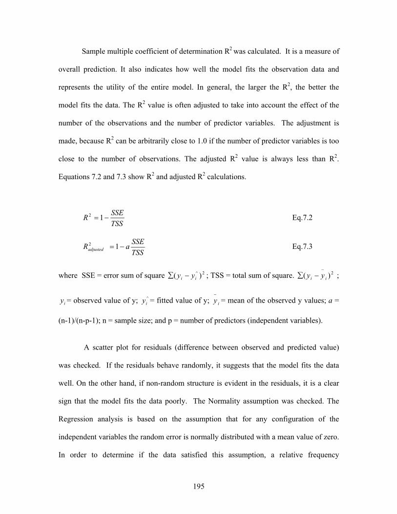
Sample multiple coefficient of determination R2 was calculated. It is a measure of
overall prediction. It also indicates how well the model fits the observation data and
represents the utility of the entire model. In general, the larger the R2, the better the
model fits the data. The R2 value is often adjusted to take into account the effect of the
number of the observations and the number of predictor variables. The adjustment is
made, because R2 can be arbitrarily close to 1.0 if the number of predictor variables is too
close to the number of observations. The adjusted R2 value is always less than R2.
Equations 7.2 and 7.3 show R2 and adjusted R2 calculations.
TSS
SSER 12 Eq.7.2
TSS
SSEaRadjusted 12 Eq.7.3
where SSE = error sum of square ; TSS = total sum of square. ;
= observed value of y; = fitted value of y; = mean of the observed y values; a =
(n-1)/(n-p-1); n = sample size; and p = number of predictors (independent variables).
2^ )( ii yy 2)( ii yy
iy ^iy iy
A scatter plot for residuals (difference between observed and predicted value)
was checked. If the residuals behave randomly, it suggests that the model fits the data
well. On the other hand, if non-random structure is evident in the residuals, it is a clear
sign that the model fits the data poorly. The Normality assumption was checked. The
Regression analysis is based on the assumption that for any configuration of the
independent variables the random error is normally distributed with a mean value of zero.
In order to determine if the data satisfied this assumption, a relative frequency
195
distribution of the residuals was required and the resulting histogram of the residuals
should not be skewed.
7.4 NONLINEAR REGRESSION ANALYSIS
Nonlinear regression aims to describe the relationship between a response variable
and one or more explanatory variables in a non-linear fashion. As pointed out in the
previous chapter, the conditions of a culvert may not decline at a constant rate over the
years of service. The rate of degradation may be very slow during the initial years and
may start increasing once a certain minimum age is reached. This suggests a nonlinear
relationship between the dependent variable (general material rating) and independent
variables. Nonlinear regression analysis was performed for the concrete and metal
culvert data by using the following model:
Y= a0 X1a1 X2
a2 … Xnan Eq. 7.4
One reason for selecting the above model was that it was used to analyze the data
in the ODOT Culvert Durability Study (ODOT 1986). A trial and error procedure was
used to find the best fit by using SPSS software. Best fit was chosen with respect to the
following:
1- Coefficient of determination R2
2- Minimum sum of squares of the difference between actual and predicted
values
196

3- Check the 95% confidence interval (C.I) for each coefficient. C.I is an interval
computed from the data that has a 95% probability of producing an interval
containing the true value of the coefficient.
7.5 COLLECTED DATA
Collected data for each culvert included inventory data and field inspection data
(primary and secondary) as shown below:
- Inventory Data
Inventory data for each culvert includes most of the following information:
1- Location (ODOT district, county, route, mile-marker)
2- Culvert shape and material
3- Culvert wall thickness (in inches)
4- Type of protective coating (if any)
5- Culvert age (in years)
6- Original dimensions (rise or diameter in feet, span in feet)
7- Information about invert paving (if any)
8- Height of cover (in feet)
9- Headwall type
10- Average daily traffic (ADT)
11- Any maintenance and past inspection records.
197

- Field Inspection Data
Includes both Primary and secondary data as shown below:
Primary Data
Primary data varies depending on the type of the culvert.
Steel Culverts
- Rise and span dimensions (to determine the deflection)
- Shape (signs of distortions and flattening)
- Steel plate surface (corrosion, pitting)
- Seams and joints (corrosion, bolt-hole cracks, opening, backfill infiltration)
- Slope and settlement including sagging
- Alignment (related to joint tightness and settlement)
- Coating (condition, bonding to steel)
- Invert paving (condition)
- Inlet and outlet conditions
Concrete Culverts
- Rise and span dimensions (in inches)
- Concrete surface conditions (signs of cracking, spalling, scalling)
- Exposed and corroding steel reinforcement bars
- Joints (opening, backfill infiltration, and cracks)
- Slope and settlement including sagging
- Alignment (related to joint tightness and settlement)
- Coating (condition, bonding to steel)
- Inlet and outlet conditions
198

Thermoplastic Culverts
- Vertical and horizontal diameters (to determine the deflection)
- Shape (signs of distortions and flattening)
- Wall surface (signs of cracking and buckling)
- Joints (opening, backfill infiltration, and cracks)
- Slope and settlement including sagging
- Alignment (related to joint tightness and settlement)
- Inlet and outlet conditions
- Backfill type and conditions.
Secondary Data
- Headwalls at inlet and outlet
- Channel inlet and outlet
- Roadway surface and guardrail
- Upstream and downstream embankment slopes (general conditions)
- Sediment depth inside the culvert
- Flow velocity
- pH of drainage water
7.6 RESULTS OF LINEAR REGRESSION ANALYSIS
This section presents the results of the linear regression analysis performed for the
concrete and metal culvert data. The analysis was made for the data based on the ODOT
and proposed rating systems. In each analysis, all four variations (FS, BE, SI, ANCOVA)
of the linear regression analysis competed to produce the best outcome.
199
Results presented here consist of standardized and unstandardized coefficients.
The standardized coefficients reflect the importance of each independent variable on the
model. They were calculated by transforming the data into the standard scale of Z-score.
Z-score for the observation X can be calculated by subtracting the mean of the data from
X and then divide it by the standard deviation of the data. The unstandardized
coefficients were calculated based on the data without any transformation.
7.6.1 Linear Regression Analysis of Metal Culvert Data
Table 7.1 presents a list of the independent variables for the metal culverts as well
as their units, ranges, and symbols.
7.6.1.1 Linear Regression Analysis of Metal Culvert Data Based on ODOT Rating System
Linear regression analysis was performed by the using general rating as the
dependant variable and all the independent variables listed in Table 7.1. The age, rise,
and culvert type were significant independent variables to predict the general rating (GR)
for the metal culverts based on the ODOT metal culvert rating system.
As shown in Table 7.2, P-values for all the variables were less than 0.05.
Therefore, the null hypothesis, Ho: ai = 0, was rejected for all the variables based on P =
0.05 as the level of significance. Table 7.2 also presents the standardized and
unstandardized coefficient values.
200

Table 7.1: Independent Variables for Metal CulvertsIndependent Variable Description Unit Range
Culvert Type (CT)
Corrugated MetalPipe (CMP) Structural Steel Plate(SSP)
---1-2
1= CMP2= SSP
Age (AG) Age of the Pipe Years 6-80
pH pH of water flowing through the pipe --- 2.8-8.8
Wall thickness (WT) Pipe wall thickness Inches 0.075-0.288
Abrasiveness (AB) Presence of abrasivematerial ( gravel,stones, or cobbles)
---1-3
1=No 2=Possible 3= Yes
Flow Velocity (FV) Flow velocity inside the pipe
---
1-4
1=Rapid ( > 2fps)2= Moderate ( 1-2 fps)3= Slow ( <1 fps)4= No flow
Sediment Depth (SD) Sediment depth inside the pipe Inches 0-14
Cover Height (CH) Height of backfill on the top of the pipe Feet 1-64
ADT Average Daily Traffic Vehicle 430-67850
Rise (RI) Rise or Diameter Inches 24-180
Table 7.2: ODOT General Rating (GR) ModelUn-standardized
CoefficientsModel Predictorsa Std. Error
StandardizedCoefficient
an
Significance(P)
Constant 7.314 1.328 0.00 0.000Age (AG) -0.049 0.017 -0.449 0.009Rise(RI) 0.033 0.010 0.596 0.002Culvert Type(CT) -1.411 0.655 -0.374 0.043
[Note] Dependent variable = General Rating (GR).
The following equation summarizes the results from Table 7.2:
GR = 7.31- 0.049(AG) +0.033(RI) -1.41(CT) Eq. 7.5
201
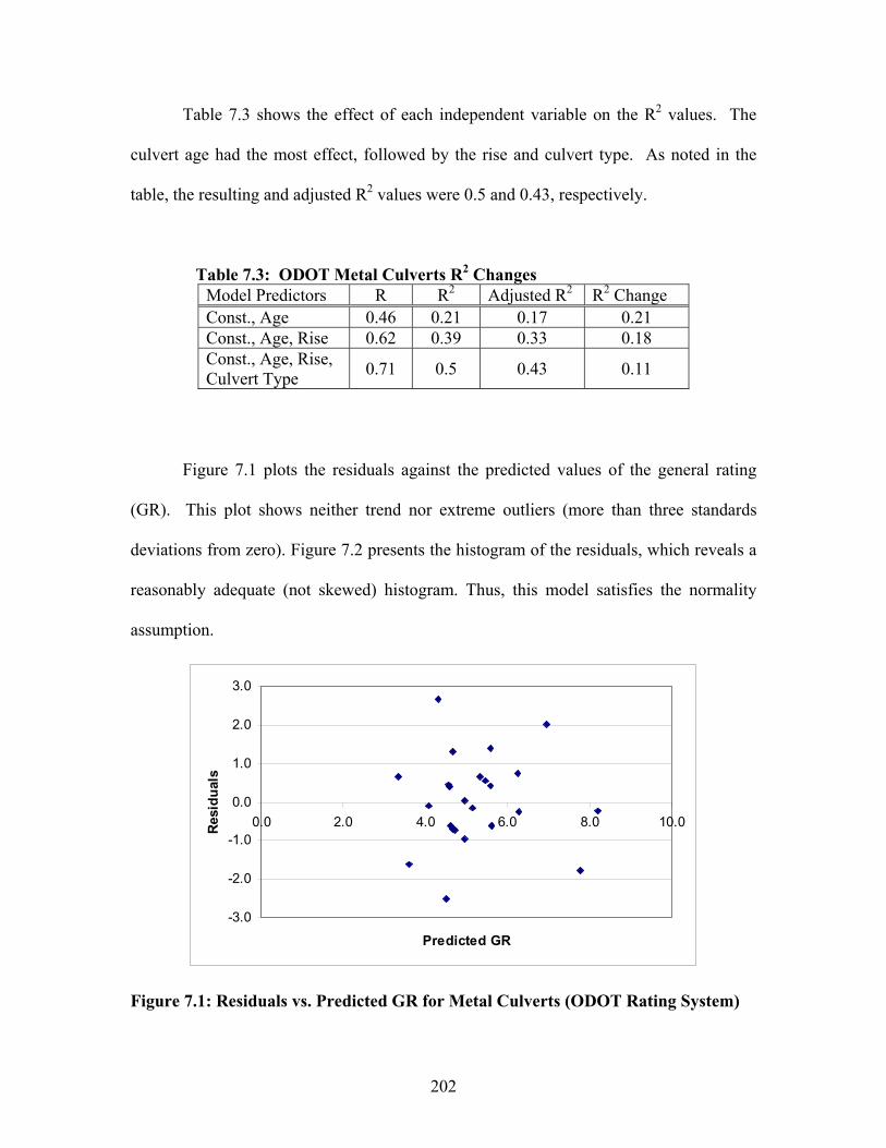
Table 7.3 shows the effect of each independent variable on the R2 values. The
culvert age had the most effect, followed by the rise and culvert type. As noted in the
table, the resulting and adjusted R2 values were 0.5 and 0.43, respectively.
Table 7.3: ODOT Metal Culverts R2 Changes Model Predictors R R2 Adjusted R2 R2 Change Const., Age 0.46 0.21 0.17 0.21Const., Age, Rise 0.62 0.39 0.33 0.18Const., Age, Rise, Culvert Type 0.71 0.5 0.43 0.11
Figure 7.1 plots the residuals against the predicted values of the general rating
(GR). This plot shows neither trend nor extreme outliers (more than three standards
deviations from zero). Figure 7.2 presents the histogram of the residuals, which reveals a
reasonably adequate (not skewed) histogram. Thus, this model satisfies the normality
assumption.
-3.0
-2.0
-1.0
0.0
1.0
2.0
3.0
0.0 2.0 4.0 6.0 8.0 10.0
Predicted GR
Res
idu
als
Figure 7.1: Residuals vs. Predicted GR for Metal Culverts (ODOT Rating System)
202
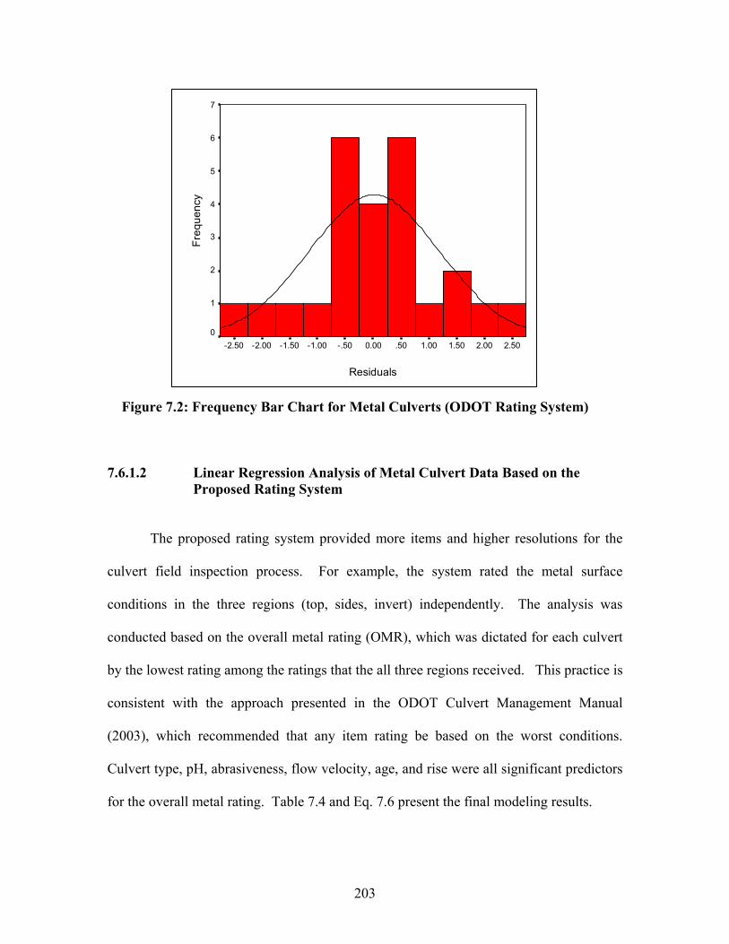
Residuals
2.502.001.501.00.500.00-.50-1.00-1.50-2.00-2.50
Fre
quen
cy
7
6
5
4
3
2
1
0
Figure 7.2: Frequency Bar Chart for Metal Culverts (ODOT Rating System)
7.6.1.2 Linear Regression Analysis of Metal Culvert Data Based on the Proposed Rating System
The proposed rating system provided more items and higher resolutions for the
culvert field inspection process. For example, the system rated the metal surface
conditions in the three regions (top, sides, invert) independently. The analysis was
conducted based on the overall metal rating (OMR), which was dictated for each culvert
by the lowest rating among the ratings that the all three regions received. This practice is
consistent with the approach presented in the ODOT Culvert Management Manual
(2003), which recommended that any item rating be based on the worst conditions.
Culvert type, pH, abrasiveness, flow velocity, age, and rise were all significant predictors
for the overall metal rating. Table 7.4 and Eq. 7.6 present the final modeling results.
203
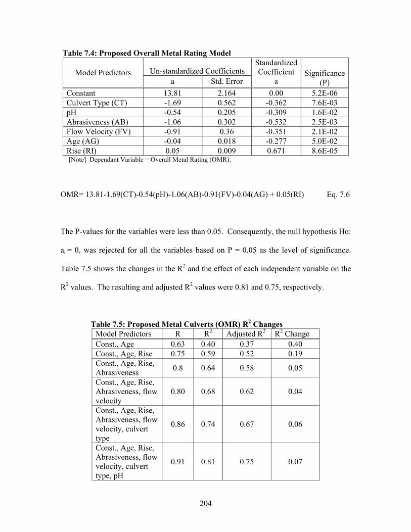
Table 7.4: Proposed Overall Metal Rating Model
Un-standardized Coefficients Model Predictorsa Std. Error
StandardizedCoefficient
aSignificance
(P)Constant 13.81 2.164 0.00 5.2E-06Culvert Type (CT) -1.69 0.562 -0.362 7.6E-03pH -0.54 0.205 -0.309 1.6E-02Abrasiveness (AB) -1.06 0.302 -0.532 2.5E-03Flow Velocity (FV) -0.91 0.36 -0.351 2.1E-02Age (AG) -0.04 0.018 -0.277 5.0E-02Rise (RI) 0.05 0.009 0.671 8.6E-05[Note] Dependant Variable = Overall Metal Rating (OMR).
OMR= 13.81-1.69(CT)-0.54(pH)-1.06(AB)-0.91(FV)-0.04(AG) + 0.05(RI) Eq. 7.6
The P-values for the variables were less than 0.05. Consequently, the null hypothesis Ho:
ai = 0, was rejected for all the variables based on P = 0.05 as the level of significance.
Table 7.5 shows the changes in the R2 and the effect of each independent variable on the
R2 values. The resulting and adjusted R2 values were 0.81 and 0.75, respectively.
Table 7.5: Proposed Metal Culverts (OMR) R2 ChangesModel Predictors R R2 Adjusted R2 R2 Change Const., Age 0.63 0.40 0.37 0.40Const., Age, Rise 0.75 0.59 0.52 0.19Const., Age, Rise, Abrasiveness 0.8 0.64 0.58 0.05
Const., Age, Rise, Abrasiveness, flow velocity
0.80 0.68 0.62 0.04
Const., Age, Rise, Abrasiveness, flow velocity, culvert type
0.86 0.74 0.67 0.06
Const., Age, Rise, Abrasiveness, flow velocity, culvert type, pH
0.91 0.81 0.75 0.07
204
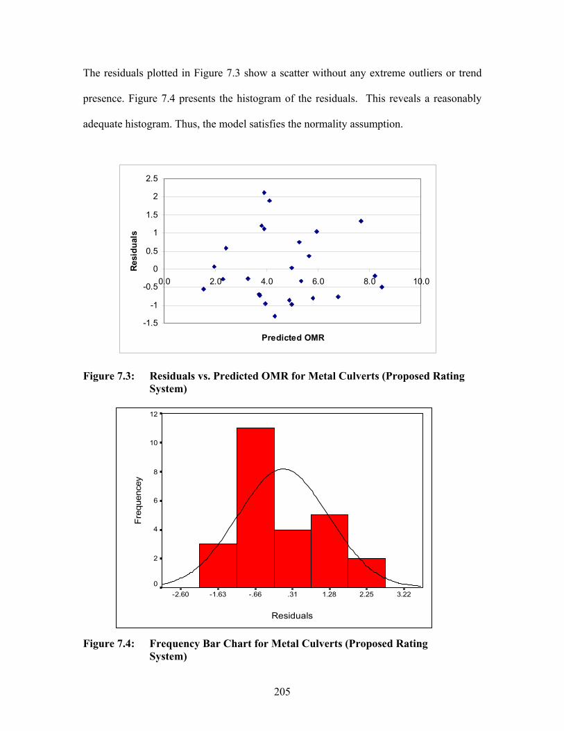
The residuals plotted in Figure 7.3 show a scatter without any extreme outliers or trend
presence. Figure 7.4 presents the histogram of the residuals. This reveals a reasonably
adequate histogram. Thus, the model satisfies the normality assumption.
-1.5
-1
-0.5
0
0.5
1
1.5
2
2.5
0.0 2.0 4.0 6.0 8.0 10.0
Predicted OMR
Res
idu
als
Figure 7.3: Residuals vs. Predicted OMR for Metal Culverts (Proposed RatingSystem)
Residuals
3.222.251.28.31-.66-1.63-2.60
Fre
quen
cey
12
10
8
6
4
2
0
Figure 7.4: Frequency Bar Chart for Metal Culverts (Proposed RatingSystem)
205
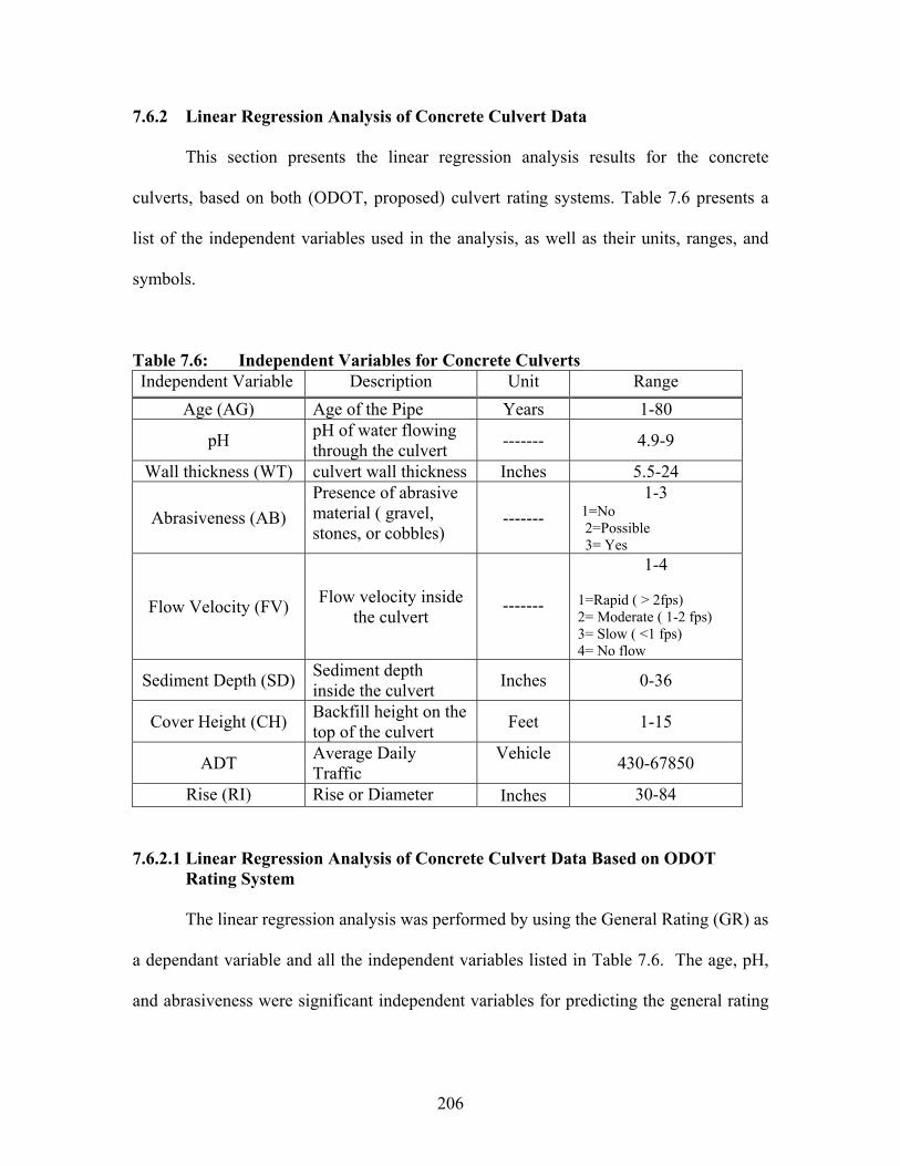
7.6.2 Linear Regression Analysis of Concrete Culvert Data
This section presents the linear regression analysis results for the concrete
culverts, based on both (ODOT, proposed) culvert rating systems. Table 7.6 presents a
list of the independent variables used in the analysis, as well as their units, ranges, and
symbols.
Table 7.6: Independent Variables for Concrete Culverts Independent Variable Description Unit Range
Age (AG) Age of the Pipe Years 1-80
pH pH of water flowing through the culvert ------- 4.9-9
Wall thickness (WT) culvert wall thickness Inches 5.5-24
Abrasiveness (AB) Presence of abrasivematerial ( gravel,stones, or cobbles)
-------1-3
1=No 2=Possible 3= Yes
Flow Velocity (FV) Flow velocity inside the culvert
-------
1-4
1=Rapid ( > 2fps)2= Moderate ( 1-2 fps)3= Slow ( <1 fps)4= No flow
Sediment Depth (SD) Sediment depth inside the culvert Inches 0-36
Cover Height (CH) Backfill height on the top of the culvert Feet 1-15
ADT Average Daily Traffic
Vehicle 430-67850
Rise (RI) Rise or Diameter Inches 30-84
7.6.2.1 Linear Regression Analysis of Concrete Culvert Data Based on ODOT Rating System
The linear regression analysis was performed by using the General Rating (GR) as
a dependant variable and all the independent variables listed in Table 7.6. The age, pH,
and abrasiveness were significant independent variables for predicting the general rating
206
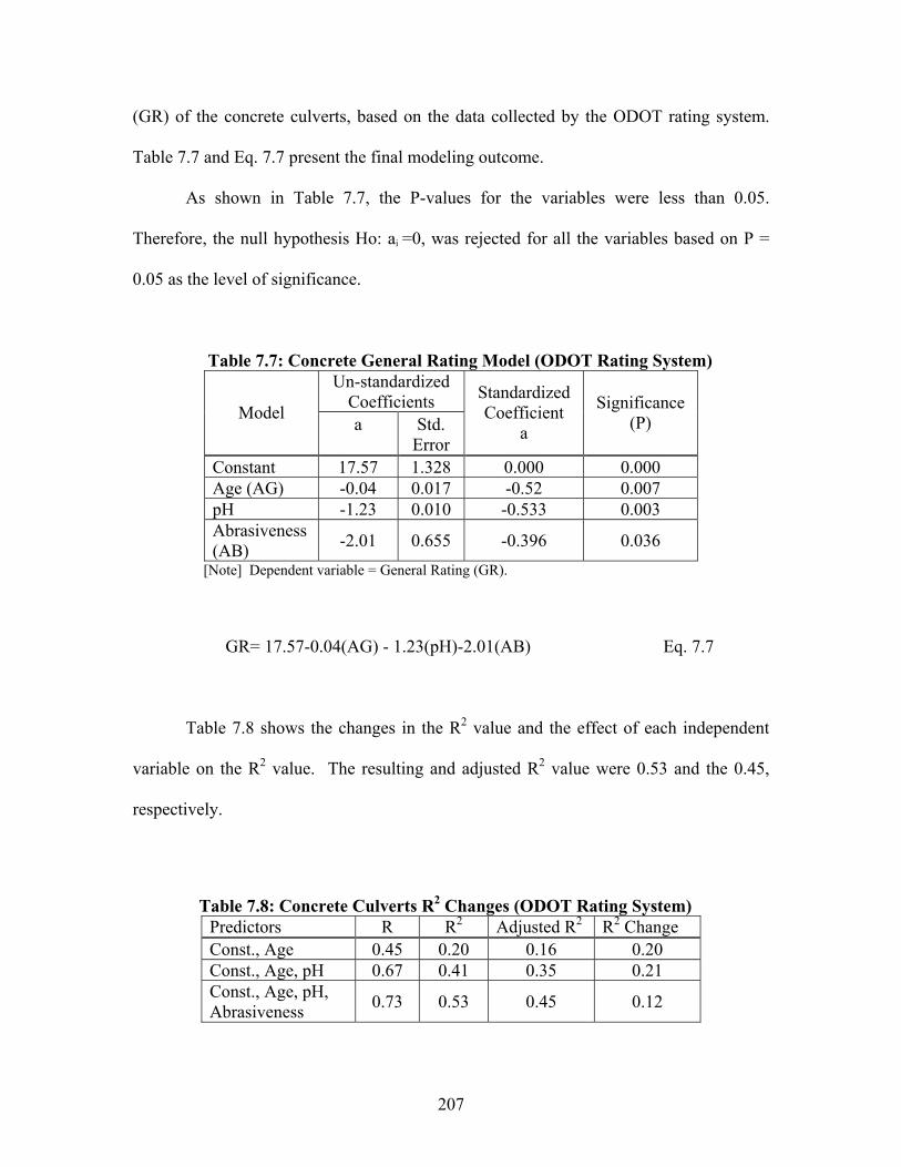
(GR) of the concrete culverts, based on the data collected by the ODOT rating system.
Table 7.7 and Eq. 7.7 present the final modeling outcome.
As shown in Table 7.7, the P-values for the variables were less than 0.05.
Therefore, the null hypothesis Ho: ai =0, was rejected for all the variables based on P =
0.05 as the level of significance.
Table 7.7: Concrete General Rating Model (ODOT Rating System) Un-standardized
CoefficientsModela Std.
Error
StandardizedCoefficient
a
Significance(P)
Constant 17.57 1.328 0.000 0.000Age (AG) -0.04 0.017 -0.52 0.007pH -1.23 0.010 -0.533 0.003Abrasiveness(AB) -2.01 0.655 -0.396 0.036
[Note] Dependent variable = General Rating (GR).
GR= 17.57-0.04(AG) - 1.23(pH)-2.01(AB) Eq. 7.7
Table 7.8 shows the changes in the R2 value and the effect of each independent
variable on the R2 value. The resulting and adjusted R2 value were 0.53 and the 0.45,
respectively.
Table 7.8: Concrete Culverts R2 Changes (ODOT Rating System) Predictors R R2 Adjusted R2 R2 Change Const., Age 0.45 0.20 0.16 0.20Const., Age, pH 0.67 0.41 0.35 0.21Const., Age, pH, Abrasiveness 0.73 0.53 0.45 0.12
207
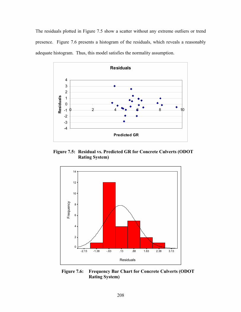
The residuals plotted in Figure 7.5 show a scatter without any extreme outliers or trend
presence. Figure 7.6 presents a histogram of the residuals, which reveals a reasonably
adequate histogram. Thus, this model satisfies the normality assumption.
Residuals
-4
-3
-2
-1
0
1
2
3
4
0 2 4 6 8
Predicted GR
Res
idu
als
10
Figure 7.5: Residual vs. Predicted GR for Concrete Culverts (ODOT Rating System)
Residuals
3.132.381.63.88.13-.63-1.38-2.13
Fre
quen
cy
14
12
10
8
6
4
2
0
Figure 7.6: Frequency Bar Chart for Concrete Culverts (ODOT Rating System)
208
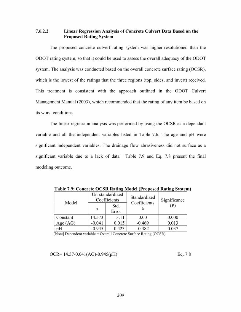
7.6.2.2 Linear Regression Analysis of Concrete Culvert Data Based on the Proposed Rating System
The proposed concrete culvert rating system was higher-resolutioned than the
ODOT rating system, so that it could be used to assess the overall adequacy of the ODOT
system. The analysis was conducted based on the overall concrete surface rating (OCSR),
which is the lowest of the ratings that the three regions (top, sides, and invert) received.
This treatment is consistent with the approach outlined in the ODOT Culvert
Management Manual (2003), which recommended that the rating of any item be based on
its worst conditions.
The linear regression analysis was performed by using the OCSR as a dependant
variable and all the independent variables listed in Table 7.6. The age and pH were
significant independent variables. The drainage flow abrasiveness did not surface as a
significant variable due to a lack of data. Table 7.9 and Eq. 7.8 present the final
modeling outcome.
Table 7.9: Concrete OCSR Rating Model (Proposed Rating System) Un-standardized
CoefficientsModela Std.
Error
StandardizedCoefficients
a
Significance(P)
Constant 14.573 3.11 0.00 0.000Age (AG) -0.041 0.015 -0.469 0.013pH -0.945 0.423 -0.382 0.037
[Note] Dependent variable = Overall Concrete Surface Rating (OCSR).
OCR= 14.57-0.041(AG)-0.945(pH) Eq. 7.8
209
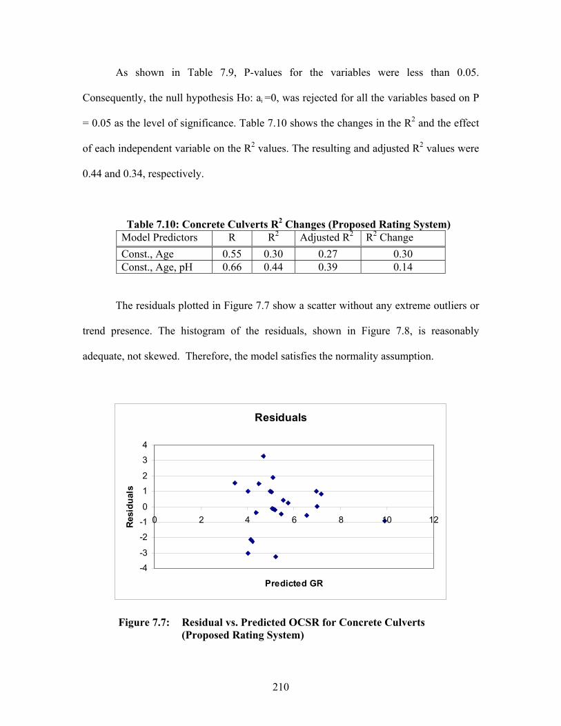
As shown in Table 7.9, P-values for the variables were less than 0.05.
Consequently, the null hypothesis Ho: ai =0, was rejected for all the variables based on P
= 0.05 as the level of significance. Table 7.10 shows the changes in the R2 and the effect
of each independent variable on the R2 values. The resulting and adjusted R2 values were
0.44 and 0.34, respectively.
Table 7.10: Concrete Culverts R2 Changes (Proposed Rating System) Model Predictors R R2 Adjusted R2 R2 Change Const., Age 0.55 0.30 0.27 0.30Const., Age, pH 0.66 0.44 0.39 0.14
The residuals plotted in Figure 7.7 show a scatter without any extreme outliers or
trend presence. The histogram of the residuals, shown in Figure 7.8, is reasonably
adequate, not skewed. Therefore, the model satisfies the normality assumption.
Residuals
-4
-3
-2
-1
0
1
2
3
4
0 2 4 6 8 10 1
Predicted GR
Res
idu
als
2
Figure 7.7: Residual vs. Predicted OCSR for Concrete Culverts (Proposed Rating System)
210

Residuals
3.02.01.00.0-1.0-2.0-3.0
Fre
quen
cy
10
8
6
4
2
0
Figure 7.8: Frequency Bar Chart for Concrete Culverts (ProposedRating System)
7.7 RESULTS OF NONLINEAR REGRESSION ANALYSIS
This section presents the results of the nonlinear regression analysis for concrete
and metal culverts based on both rating systems.
7.7.1 Nonlinear Regression Analysis for Metal Culverts
Nonlinear regression analysis was performed by using both the ODOT and
proposed rating systems. Age was the only significant independent variable to predict the
GR for the ODOT rating system. The age, pH, and wall thickness were significant
independent variables to predict the OMR in the proposed rating system. Table 7.11 and
Equations 7.9 and 7.10 present the final results for both models.
211

Table 7.11 Metal Culverts Nonlinear Models Coefficients 95% C.I* for anRating
systemDependentVariable
IndependentVariables a0 an Lower Upper
R2
ODOT GeneralRating (GR) Age 12.95 a1= -0.25 -0.41 -0.09 0.25
Age a1=-0.43 -0.64 -0.23pH a2=-0.79 -1.40 -0.17Proposed Overall Metal
Rating(OMR)Wall Thick.
390.93 a3=0.71 0.133 1.28
0.51
*C.I= confidence Interval
GR = 12.95(Age)-0.25 ODOT Rating System Eq. 7.9
OMR = 390.93(Age)-0.43 (pH)-0.79 (Thick.)0.71 Proposed Rating System Eq. 7.10
The results of the nonlinear regression analysis for the metal culverts show that
the proposed rating system detected more significant variables and had a higher value of
R2. The results also show that the culvert conditions may not decline at a constant rate
over the years of service.
7.7.2 Nonlinear Analysis for Concrete Culverts
The nonlinear regression analysis was performed for concrete culverts by using
both rating systems. The age was the only significant independent variable to predict the
GR and OCSR in both rating systems. Table 7.12, Eq. 7.11, and Eq. 7.12 present the final
outcome of the nonlinear modeling.
212
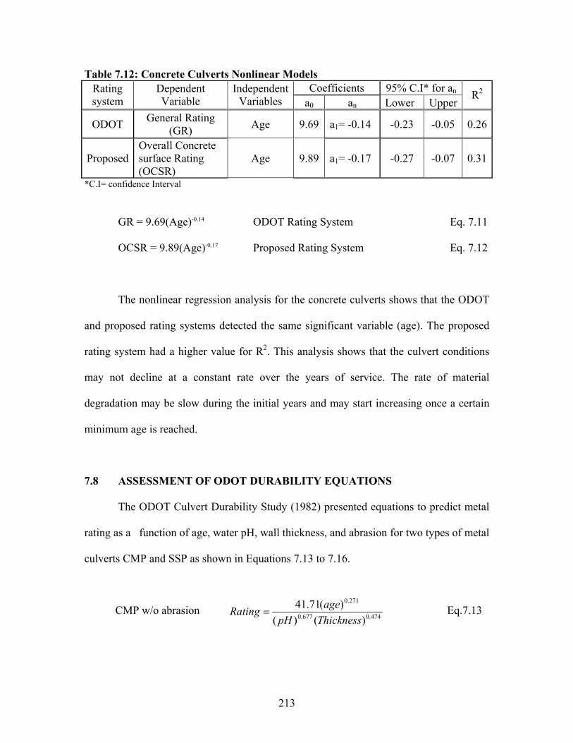
Table 7.12: Concrete Culverts Nonlinear ModelsCoefficients 95% C.I* for anRating
systemDependentVariable
IndependentVariables a0 an Lower Upper
R2
ODOT General Rating (GR) Age 9.69 a1= -0.14 -0.23 -0.05 0.26
ProposedOverall Concretesurface Rating(OCSR)
Age 9.89 a1= -0.17 -0.27 -0.07 0.31
*C.I= confidence Interval
GR = 9.69(Age)-0.14 ODOT Rating System Eq. 7.11
OCSR = 9.89(Age)-0.17 Proposed Rating System Eq. 7.12
The nonlinear regression analysis for the concrete culverts shows that the ODOT
and proposed rating systems detected the same significant variable (age). The proposed
rating system had a higher value for R2. This analysis shows that the culvert conditions
may not decline at a constant rate over the years of service. The rate of material
degradation may be slow during the initial years and may start increasing once a certain
minimum age is reached.
7.8 ASSESSMENT OF ODOT DURABILITY EQUATIONS
The ODOT Culvert Durability Study (1982) presented equations to predict metal
rating as a function of age, water pH, wall thickness, and abrasion for two types of metal
culverts CMP and SSP as shown in Equations 7.13 to 7.16.
CMP w/o abrasion Eq.7.13474.0677.0
271.0
)()()(71.41
ThicknesspH
ageRating
213
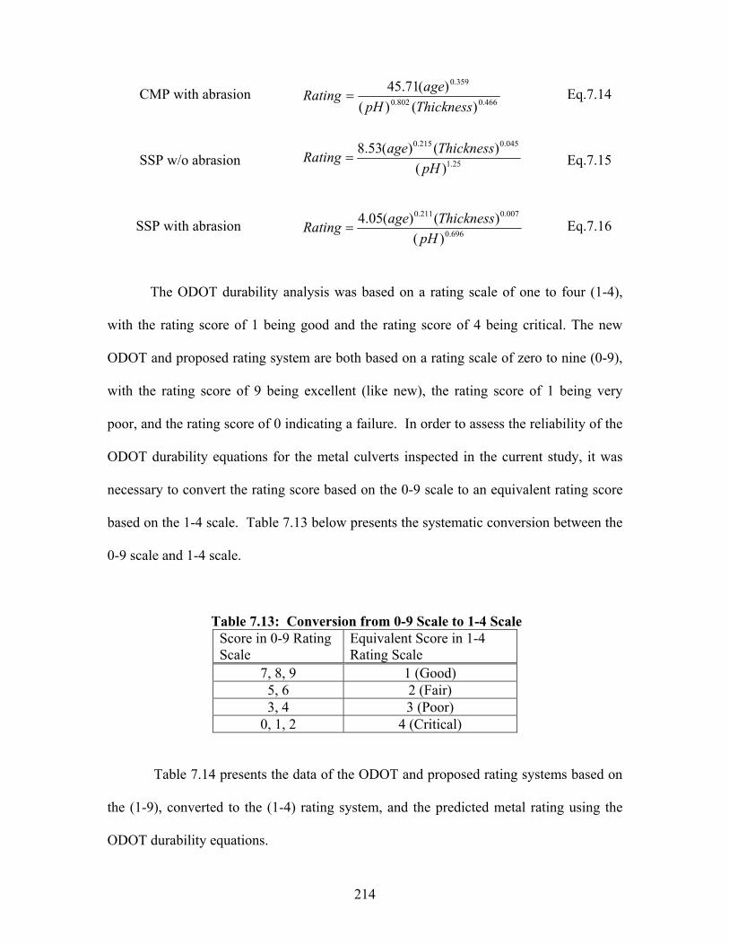
CMP with abrasion Eq.7.14 466.0802.0
359.0
)()()(71.45
ThicknesspH
ageRating
SSP w/o abrasion Eq.7.15 25.1
045.0215.0
)()()(53.8
pH
ThicknessageRating
SSP with abrasion Eq.7.16 696.0
007.0211.0
)()()(05.4
pH
ThicknessageRating
The ODOT durability analysis was based on a rating scale of one to four (1-4),
with the rating score of 1 being good and the rating score of 4 being critical. The new
ODOT and proposed rating system are both based on a rating scale of zero to nine (0-9),
with the rating score of 9 being excellent (like new), the rating score of 1 being very
poor, and the rating score of 0 indicating a failure. In order to assess the reliability of the
ODOT durability equations for the metal culverts inspected in the current study, it was
necessary to convert the rating score based on the 0-9 scale to an equivalent rating score
based on the 1-4 scale. Table 7.13 below presents the systematic conversion between the
0-9 scale and 1-4 scale.
Table 7.13: Conversion from 0-9 Scale to 1-4 Scale Score in 0-9 Rating Scale
Equivalent Score in 1-4 Rating Scale
7, 8, 9 1 (Good) 5, 6 2 (Fair) 3, 4 3 (Poor)
0, 1, 2 4 (Critical)
Table 7.14 presents the data of the ODOT and proposed rating systems based on
the (1-9), converted to the (1-4) rating system, and the predicted metal rating using the
ODOT durability equations.
214
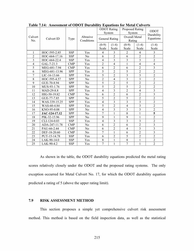
Table 7.14: Assessment of ODOT Durability Equations for Metal Culverts ODOT Rating
SystemProposed Rating
System
General Rating Overall Metal Rating
ODOTDurabilityEquationsCulvert
No. Culvert ID Type AbrasiveConditions
(0-9)Scale
(1-4)Scale
(0-9)Scale
(1-4)Scale
(1-4)Scale
1 HOC-595-2.85 SSP Yes 4 3 2 4 32 HOC-664-17.16 SSP No 6 2 6 2 23 HOC-664-22.4 SSP Yes 4 3 3 3 24 GAL-7-21.3 CMP Yes 2 4 1 4 45 MEG-681-7.94 CMP Yes 6 2 6 2 36 MEG-681-13.96 SPP Yes 5 2 5 2 27 LIC-16-13.66 SPP Yes 5 2 3 3 28 HOC-595-4.57 SPP No 2 4 3 3 29 GUE-70-8.94 SPP No 5 2 5 2 2
10 MUS-93-1.76 SPP No 5 2 5 2 211 MAD-29-8.8 SPP Yes 4 3 2 4 312 HIG-50-19.82 CMP No 6 2 6 2 313 GUE-77-7.85 SPP No 5 2 5 2 214 WAS-339-15.25 SPP Yes 4 3 3 3 215 WAS-60-4.84 SPP Yes 5 2 4 3 216 KNO-95-0.08 SPP No 4 3 3 3 217 JAC-124-17.12 SPP No 7 1 8 1 518 PIK-32-15.96 SPP No 9 1 9 1 219 CLI-124-0.03 SSP Yes 4 3 3 3 220 ADA-247-11.78 CMP No 6 2 6 2 321 PAU-66-2.44 CMP No 6 2 4 3 322 DEF-18-20.60 CMP No 7 1 6 2 323 PUT-15-14.78 SSP Yes 6 2 5 2 224 LAK-90-14.0 SSP Yes 8 1 8 1 225 LAK-90-4.2 SSP Yes 7 1 7 1 2
As shown in the table, the ODOT durability equations predicted the metal rating
scores relatively closely under the ODOT and the proposed rating systems. The only
exception occurred for Metal Culvert No. 17, for which the ODOT durability equation
predicted a rating of 5 (above the upper rating limit).
7.9 RISK ASSESSMENT METHOD
This section proposes a simple yet comprehensive culvert risk assessment
method. This method is based on the field inspection data, as well as the statistical
215

analysis results. For either the ODOT or the proposed culvert rating system, the method
takes the original average culvert rating score (total score divided by the number of rated
items) and adjusts it by considering the culvert age, pH of drainage water, abrasiveness of
the drainage flow, and the cover height (H) to rise or diameter (R) ratio. This last factor is
incorporated here, because the risk to motorists tends to be greater when the H/R ratio is
lower. This concept is presented in Eqs. 7.17 and 7.18:
AOR= M1* M2 * M3 *M4* (OAR) for Metal & Concrete Culverts Eq. 7.17
AOR= M4* (OAR) for Plastic Pipe Culverts Eq. 7.18
where AOR= adjusted overall rating score; M1= rating modifier due to culvert age; M2=
rating modifier due to water pH; M3 = rating modifier due to abrasiveness of drainage
flow; M4= rating modifier due to H/R ratio; and OAR= original average rating score.
Linear form was utilized here for the ease of application and due to a lack of
comprehensive data correlating the rate of culvert material deterioration over time. A
similar but less comprehensive approach has been taken by the others to develop a culvert
risk assessment model (McGrath and Beaver, 2003). The AOR score for the
thermoplastic pipe culvert is adjusted by the H/R factor only, because the thermoplastic
materials do not age like metals and concrete (more chemically stable) and that they are
also more abrasion resistant.
216

Tables 7.15 (a) through (d) present proposed modifier values. The age modifier
(M1) values are based on the culvert age and rating analysis presented at the end of
Chapter 6. Flow abrasiveness, pH, and the H/R ratio modifier (M2, M3, M4) values are
based on the results of statistical analysis and literature review. There was initially an
idea to introduce the fifth modifier that is based on the ADT classifications of the
roadway the culvert is associated with. However, this idea was abandoned because of its
potentially controversial nature.
Table 7.15.(a): Value of Age ModifierAge Modifier Value Culvert Age (yrs.)
Concrete MetalLess than 20 1.0 1.0
20 - 40 0.95 0.940 -60 0.9 0.85
More than 60 0.85 0.8
Table 7.15.(b): Value of pH Modifier pH pH Modifier Value
More Than 7.0 15.0 - 7.0 0.95
Less Than 5.0 0.9
Table 7.15.(c): Value of Abrasiveness ModifierCondition Abrasiveness Modifier ValueAbrasive 0.9
Non-Abrasive 1.0
Table 7.15.(d): Value of H/R Ratio Modifier H/R Ratio H/R Ratio Modifier Value
More than 5 12.5 – 5 0.9
Less than 2.5 0.85
217
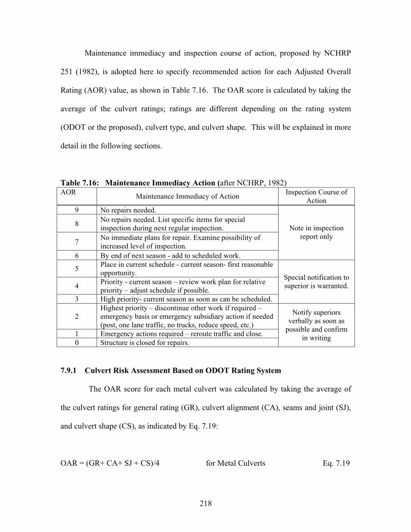
Maintenance immediacy and inspection course of action, proposed by NCHRP
251 (1982), is adopted here to specify recommended action for each Adjusted Overall
Rating (AOR) value, as shown in Table 7.16. The OAR score is calculated by taking the
average of the culvert ratings; ratings are different depending on the rating system
(ODOT or the proposed), culvert type, and culvert shape. This will be explained in more
detail in the following sections.
Table 7.16: Maintenance Immediacy Action (after NCHRP, 1982) AOR Maintenance Immediacy of Action Inspection Course of
Action9 No repairs needed.
8 No repairs needed. List specific items for special inspection during next regular inspection.
7 No immediate plans for repair. Examine possibility ofincreased level of inspection.
6 By end of next season - add to scheduled work.
Note in inspection report only
5 Place in current schedule - current season- first reasonable opportunity.
4 Priority - current season – review work plan for relative priority – adjust schedule if possible.
3 High priority- current season as soon as can be scheduled.
Special notification to superior is warranted.
2Highest priority – discontinue other work if required – emergency basis or emergency subsidiary action if needed(post, one lane traffic, no trucks, reduce speed, etc.)
1 Emergency actions required – reroute traffic and close. 0 Structure is closed for repairs.
Notify superiorsverbally as soon as
possible and confirmin writing
7.9.1 Culvert Risk Assessment Based on ODOT Rating System
The OAR score for each metal culvert was calculated by taking the average of
the culvert ratings for general rating (GR), culvert alignment (CA), seams and joint (SJ),
and culvert shape (CS), as indicated by Eq. 7.19:
OAR = (GR+ CA+ SJ + CS)/4 for Metal Culverts Eq. 7.19
218

The AOR was calculated by adjusting the OAR due to the age, water pH, flow
abrasiveness, and the H/R ratio modifiers, as shown by Eq. 7.17. Table 7.17 presents the
risk assessment calculations for the metal culverts based on the ODOT rating system.
The AOR was between 2 and 6. Based on Tables 7.17 and 7.16, maintenance immediacy
action for Metal Culverts No.3 and 16 are highest and high priority, respectively. The
AOR for the rest of the culverts were between 4 and 6, and their maintenance immediacy
actions were between 4 (priority - current season) and 6 (by end of next season - add to
scheduled work). It is interesting to note that for almost half of the metal culverts the
AOR was the same as the lowest of the four (GR, CA, CS, SJ) rating scores.
Table 7.17: Metal Culverts Risk Assessment Based on ODOT Rating System No Culvert ID GR CA CS SJ OAR AOR1 HOC-595-2.85 4 8 7 7 7 42 HOC-664-17.16 6 8 8 8 8 53 HOC-664-22.4 4 3 3 2 3 24 GAL-7-21.3 2 3 NA* 2 NA* NA*5 MEG-681-7.94 6 8 5 7 7 46 MEG-681-13.96 5 8 8 7 7 47 LIC-16-13.66 5 6 7 7 6 48 HOC-595-4.57 2 7 6 8 6 49 GUE-70-8.94 5 9 3 8 6 6
10 MUS-93-1.76 5 8 4 6 6 411 MAD-29-8.8 4 8 6 7 6 412 HIG-50-19.82 6 8 7 7 7 613 GUE-77-7.85 5 8 6 7 7 614 WAS-339-15.25 4 8 8 8 7 415 WAS-60-4.84 5 8 5 5 6 416 KNO-95-0.08 4 6 3 4 4 317 JAC-124-17.12 7 7 5 7 7 418 PIK-32-15.96 9 8 6 7 8 619 CLI-124-0.03 4 7 7 6 6 420 ADA-247-11.78 6 8 6 7 7 521 PAU-66-2.44 6 8 5 7 7 522 DEF-18-20.60 7 7 4 8 7 423 PUT-15-14.78 6 8 6 8 7 424 LAK-90-14.0 8 9 8 8 8 525 LAK-90-4.2 7 8 8 8 8 6
*NA= Not Available.
219
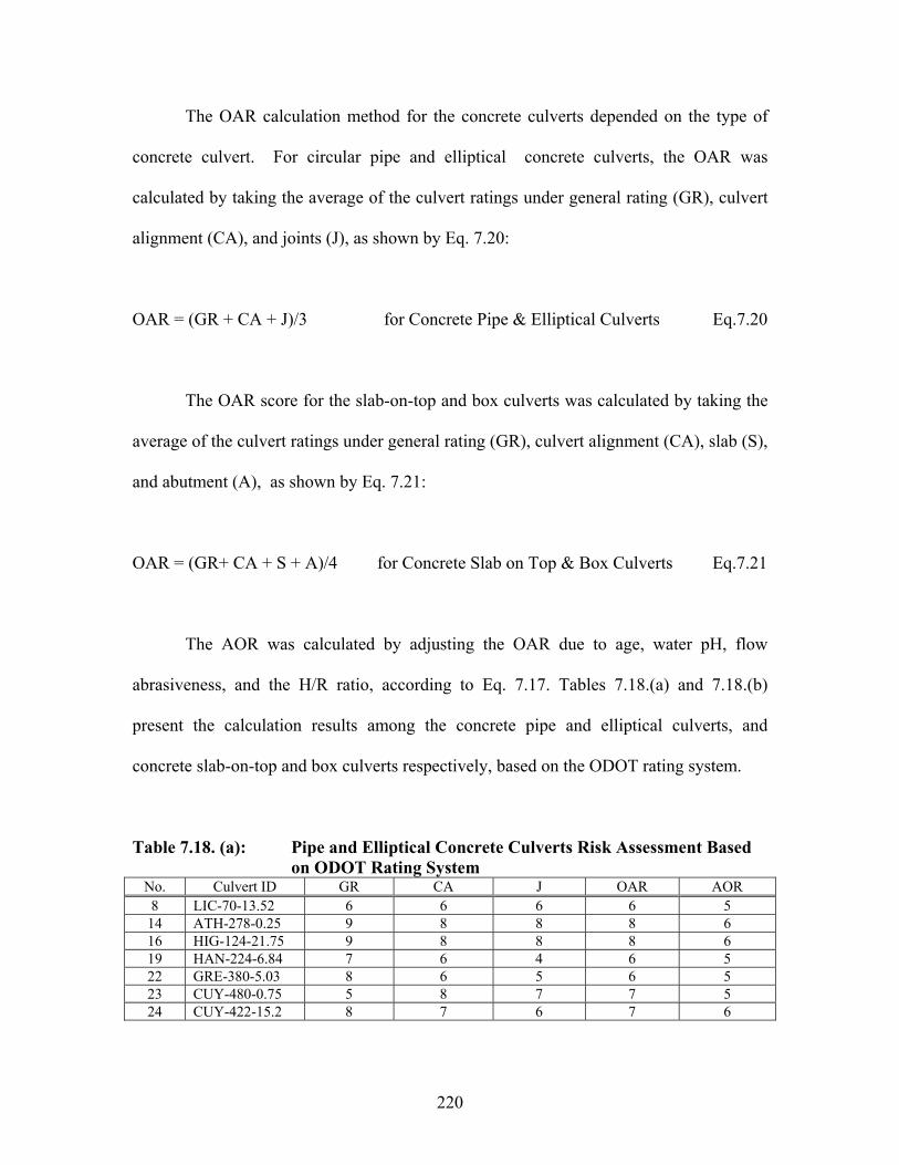
The OAR calculation method for the concrete culverts depended on the type of
concrete culvert. For circular pipe and elliptical concrete culverts, the OAR was
calculated by taking the average of the culvert ratings under general rating (GR), culvert
alignment (CA), and joints (J), as shown by Eq. 7.20:
OAR = (GR + CA + J)/3 for Concrete Pipe & Elliptical Culverts Eq.7.20
The OAR score for the slab-on-top and box culverts was calculated by taking the
average of the culvert ratings under general rating (GR), culvert alignment (CA), slab (S),
and abutment (A), as shown by Eq. 7.21:
OAR = (GR+ CA + S + A)/4 for Concrete Slab on Top & Box Culverts Eq.7.21
The AOR was calculated by adjusting the OAR due to age, water pH, flow
abrasiveness, and the H/R ratio, according to Eq. 7.17. Tables 7.18.(a) and 7.18.(b)
present the calculation results among the concrete pipe and elliptical culverts, and
concrete slab-on-top and box culverts respectively, based on the ODOT rating system.
Table 7.18. (a): Pipe and Elliptical Concrete Culverts Risk Assessment Based on ODOT Rating System
No. Culvert ID GR CA J OAR AOR8 LIC-70-13.52 6 6 6 6 5
14 ATH-278-0.25 9 8 8 8 616 HIG-124-21.75 9 8 8 8 619 HAN-224-6.84 7 6 4 6 522 GRE-380-5.03 8 6 5 6 523 CUY-480-0.75 5 8 7 7 524 CUY-422-15.2 8 7 6 7 6
220
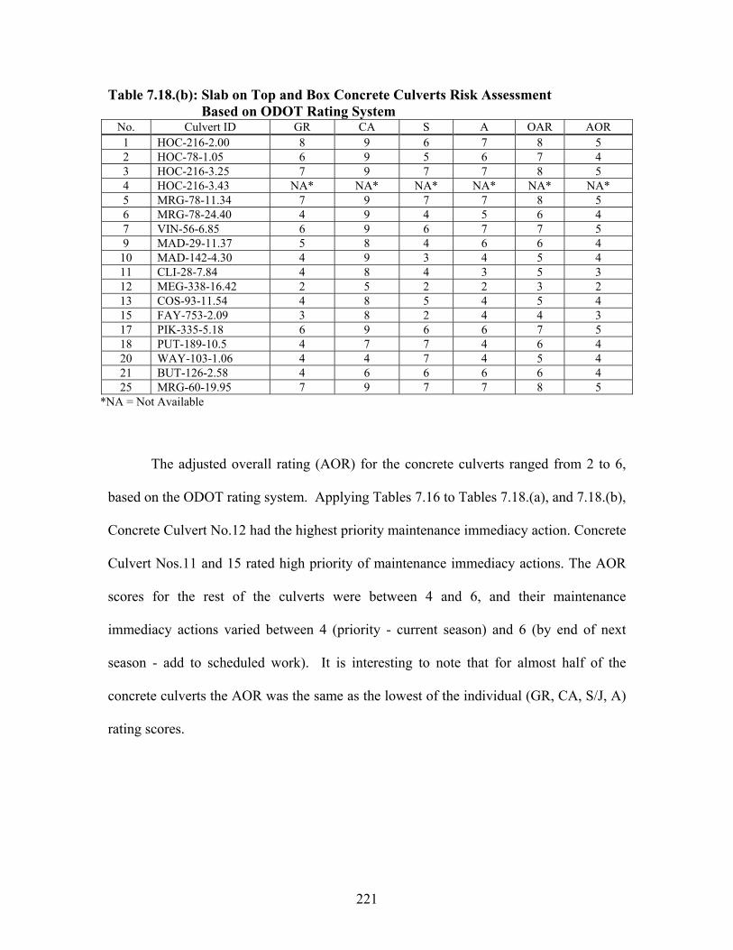
Table 7.18.(b): Slab on Top and Box Concrete Culverts Risk Assessment Based on ODOT Rating System
No. Culvert ID GR CA S A OAR AOR1 HOC-216-2.00 8 9 6 7 8 52 HOC-78-1.05 6 9 5 6 7 43 HOC-216-3.25 7 9 7 7 8 54 HOC-216-3.43 NA* NA* NA* NA* NA* NA*5 MRG-78-11.34 7 9 7 7 8 56 MRG-78-24.40 4 9 4 5 6 47 VIN-56-6.85 6 9 6 7 7 59 MAD-29-11.37 5 8 4 6 6 4
10 MAD-142-4.30 4 9 3 4 5 411 CLI-28-7.84 4 8 4 3 5 312 MEG-338-16.42 2 5 2 2 3 213 COS-93-11.54 4 8 5 4 5 415 FAY-753-2.09 3 8 2 4 4 317 PIK-335-5.18 6 9 6 6 7 518 PUT-189-10.5 4 7 7 4 6 420 WAY-103-1.06 4 4 7 4 5 421 BUT-126-2.58 4 6 6 6 6 425 MRG-60-19.95 7 9 7 7 8 5
*NA = Not Available
The adjusted overall rating (AOR) for the concrete culverts ranged from 2 to 6,
based on the ODOT rating system. Applying Tables 7.16 to Tables 7.18.(a), and 7.18.(b),
Concrete Culvert No.12 had the highest priority maintenance immediacy action. Concrete
Culvert Nos.11 and 15 rated high priority of maintenance immediacy actions. The AOR
scores for the rest of the culverts were between 4 and 6, and their maintenance
immediacy actions varied between 4 (priority - current season) and 6 (by end of next
season - add to scheduled work). It is interesting to note that for almost half of the
concrete culverts the AOR was the same as the lowest of the individual (GR, CA, S/J, A)
rating scores.
221
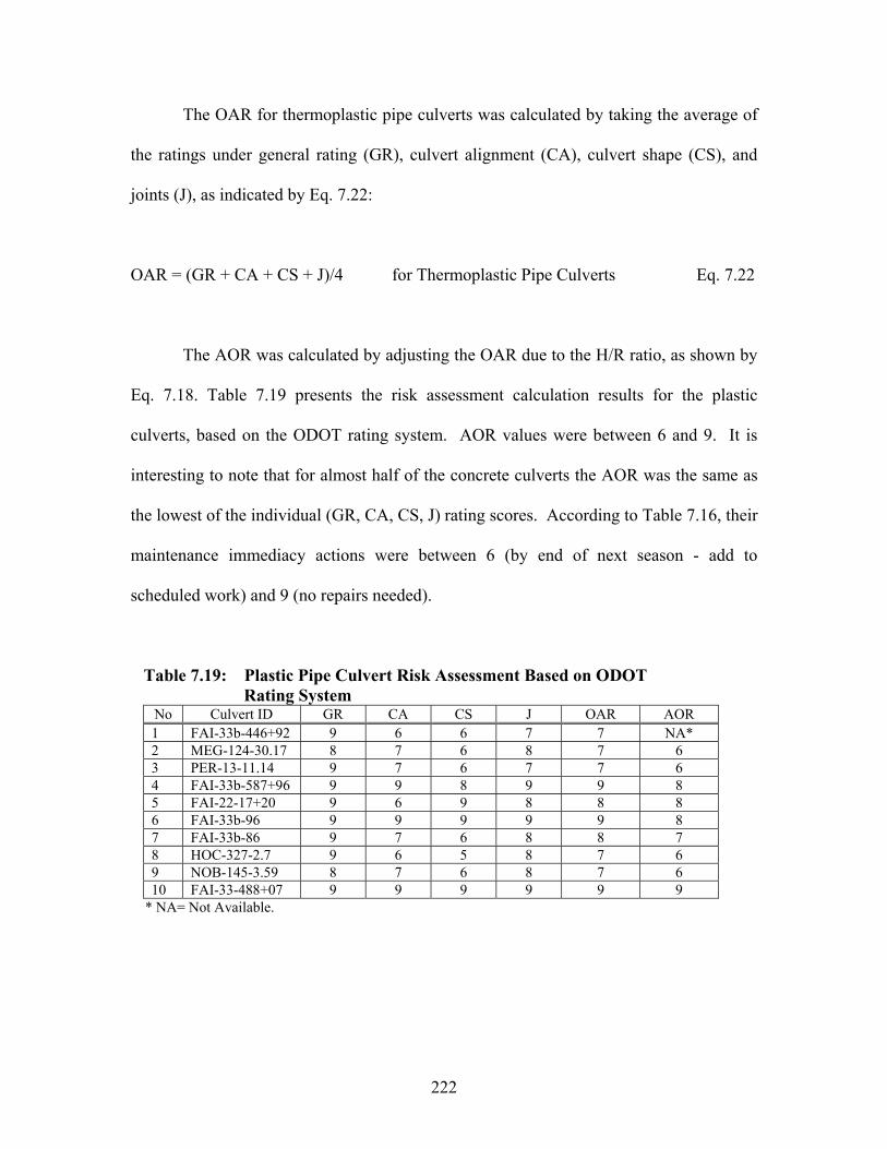
The OAR for thermoplastic pipe culverts was calculated by taking the average of
the ratings under general rating (GR), culvert alignment (CA), culvert shape (CS), and
joints (J), as indicated by Eq. 7.22:
OAR = (GR + CA + CS + J)/4 for Thermoplastic Pipe Culverts Eq. 7.22
The AOR was calculated by adjusting the OAR due to the H/R ratio, as shown by
Eq. 7.18. Table 7.19 presents the risk assessment calculation results for the plastic
culverts, based on the ODOT rating system. AOR values were between 6 and 9. It is
interesting to note that for almost half of the concrete culverts the AOR was the same as
the lowest of the individual (GR, CA, CS, J) rating scores. According to Table 7.16, their
maintenance immediacy actions were between 6 (by end of next season - add to
scheduled work) and 9 (no repairs needed).
Table 7.19: Plastic Pipe Culvert Risk Assessment Based on ODOT Rating System
No Culvert ID GR CA CS J OAR AOR1 FAI-33b-446+92 9 6 6 7 7 NA*2 MEG-124-30.17 8 7 6 8 7 63 PER-13-11.14 9 7 6 7 7 64 FAI-33b-587+96 9 9 8 9 9 85 FAI-22-17+20 9 6 9 8 8 86 FAI-33b-96 9 9 9 9 9 87 FAI-33b-86 9 7 6 8 8 78 HOC-327-2.7 9 6 5 8 7 69 NOB-145-3.59 8 7 6 8 7 610 FAI-33-488+07 9 9 9 9 9 9
* NA= Not Available.
222

7.9.2 Culvert Risk Assessment Based on Proposed Rating System
For the proposed rating system, the OAR score for the metal culverts was
calculated by taking the average of the culvert ratings for metal plate (MP), horizontal
alignment (HA), seams and joint (SJ), culvert shape (CS), slope and settlement (SS), and
culvert deflection (CD), as shown by Eq. 7.23:
OAR = (MP + HA + SJ + CS + SS+ CD)/6 for Metal Culverts Eq.7.23
The AOR was calculated by adjusting the OAR due to age, water pH, flow
abrasiveness, and the H/R ratio, as indicated by Eq. 7.17. Table 7.17 presents the risk
assessment calculation results for metal culverts, based on the proposed rating system.
Adjusted overall rating (AOR) for the metal culverts was between 2 and 6. It is noted
that for only about ¼ of the metal culverts the AOR was equal to the lowest of the
individual rating scores. Based on Tables 7.16 and 7.20, Metal Culvert Nos. 3 and 7
yielded the highest and high priority for maintenance immediacy actions, respectively.
The rest of the culverts’ adjusted overall rating (AOR) scores were between 4 and 6.
Thus, their maintenance immediacy actions fell between 4 (priority - current season) and
6 (by end of next season - add to scheduled work).
Table 7.20: Metal Culverts Risk Assessment Based on Proposed Rating System No. Culvert ID MP HA SJ CS SS CD OAR AOR1 HOC-595-2.85 2 8 7 7 7 7 6 42 HOC-664-17.16 6 8 8 7 7 7 7 53 HOC-664-22.4 3 3 1 2 3 5 3 24 GAL-7-21.3 1 2 1 NA* 2 NA* NA* NA*5 MEG-681-7.94 6 8 6 5 7 5 6 46 MEG-681-13.96 5 8 7 7 8 7 7 47 LIC-16-13.66 3 7 5 7 6 6 6 38 HOC-595-4.57 3 8 5 8 6 8 6 4
* NA= Not Available.
223
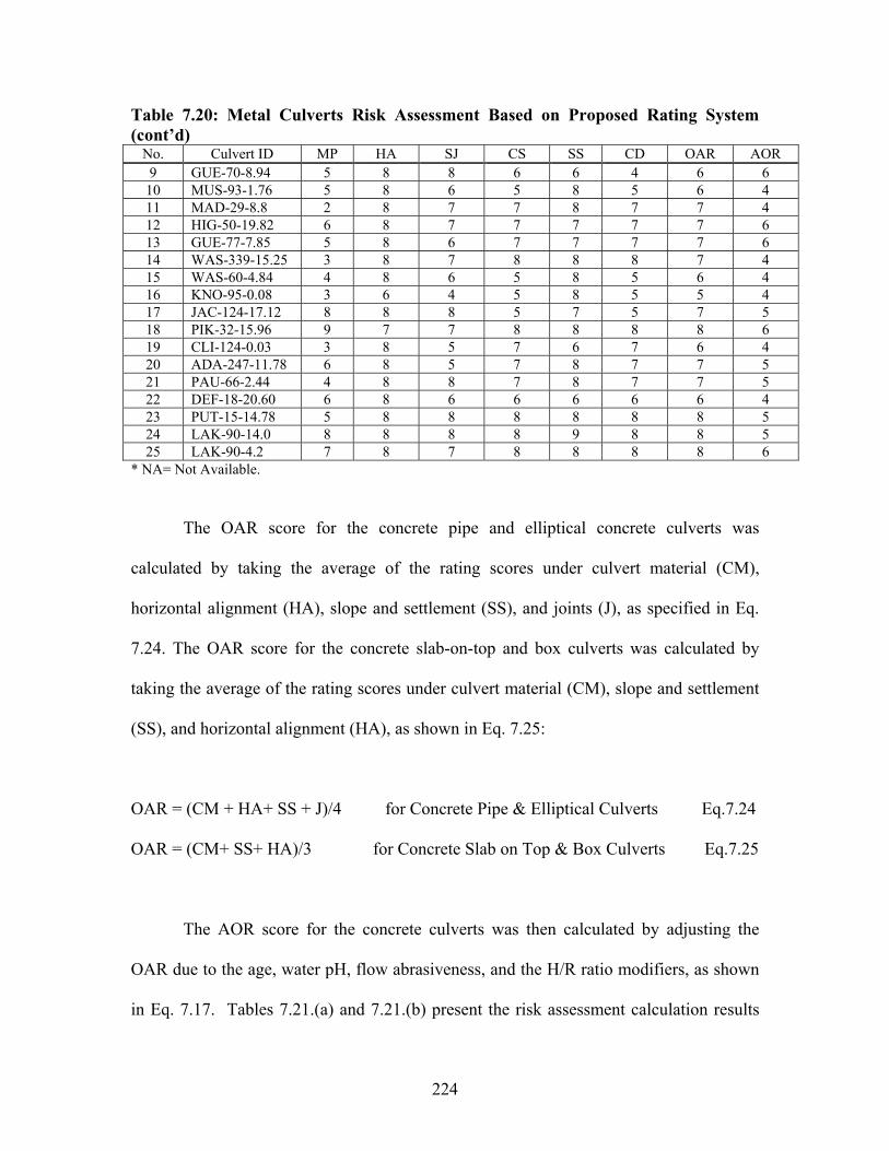
Table 7.20: Metal Culverts Risk Assessment Based on Proposed Rating System (cont’d)
No. Culvert ID MP HA SJ CS SS CD OAR AOR9 GUE-70-8.94 5 8 8 6 6 4 6 6
10 MUS-93-1.76 5 8 6 5 8 5 6 411 MAD-29-8.8 2 8 7 7 8 7 7 412 HIG-50-19.82 6 8 7 7 7 7 7 613 GUE-77-7.85 5 8 6 7 7 7 7 614 WAS-339-15.25 3 8 7 8 8 8 7 415 WAS-60-4.84 4 8 6 5 8 5 6 416 KNO-95-0.08 3 6 4 5 8 5 5 417 JAC-124-17.12 8 8 8 5 7 5 7 518 PIK-32-15.96 9 7 7 8 8 8 8 619 CLI-124-0.03 3 8 5 7 6 7 6 420 ADA-247-11.78 6 8 5 7 8 7 7 521 PAU-66-2.44 4 8 8 7 8 7 7 522 DEF-18-20.60 6 8 6 6 6 6 6 423 PUT-15-14.78 5 8 8 8 8 8 8 524 LAK-90-14.0 8 8 8 8 9 8 8 525 LAK-90-4.2 7 8 7 8 8 8 8 6
* NA= Not Available.
The OAR score for the concrete pipe and elliptical concrete culverts was
calculated by taking the average of the rating scores under culvert material (CM),
horizontal alignment (HA), slope and settlement (SS), and joints (J), as specified in Eq.
7.24. The OAR score for the concrete slab-on-top and box culverts was calculated by
taking the average of the rating scores under culvert material (CM), slope and settlement
(SS), and horizontal alignment (HA), as shown in Eq. 7.25:
OAR = (CM + HA+ SS + J)/4 for Concrete Pipe & Elliptical Culverts Eq.7.24
OAR = (CM+ SS+ HA)/3 for Concrete Slab on Top & Box Culverts Eq.7.25
The AOR score for the concrete culverts was then calculated by adjusting the
OAR due to the age, water pH, flow abrasiveness, and the H/R ratio modifiers, as shown
in Eq. 7.17. Tables 7.21.(a) and 7.21.(b) present the risk assessment calculation results
224

for the concrete pipe and elliptical culverts, and concrete slab-on-top and box culverts
based, using the data collected through the proposed rating system.
Table 7.21.(a): Pipe and Elliptical Concrete Culverts Risk Assessment Based on Proposed Rating System
No. Culvert ID CM HA J SS OAR AOR8 LIC-70-13.52 6 7 7 6 7 6
14 ATH-278-0.25 6 6 6 6 6 516 HIG-124-21.75 8 8 6 6 7 519 HAN-224-6.84 6 8 7 8 7 622 GRE-380-5.03 8 8 8 7 8 723 CUY-480-0.75 9 8 7 7 8 624 CUY-422-15.2 8 9 8 9 9 7
Table 7.21.(b): Slab on Top and Box Concrete Culverts Risk AssessmentBased on Proposed Rating System
No. Culvert ID CM SS HA OAR AOR1 HOC-216-2.00 7 9 8 8 62 HOC-78-1.05 5 9 8 7 53 HOC-216-3.25 5 8 8 7 54 HOC-216-3.43 NA* NA* 8 NA* NA*5 MRG-78-11.34 5 9 8 7 56 MRG-78-24.40 5 7 8 7 57 VIN-56-6.85 6 9 8 8 69 MAD-29-11.37 6 8 8 7 5
10 MAD-142-4.30 5 8 8 7 511 CLI-28-7.84 1 8 8 6 412 MEG-338-16.42 2 4 8 5 313 COS-93-11.54 4 8 8 7 515 ATH-278-0.25 2 8 8 6 417 PIK-335-5.18 6 9 8 8 618 PUT-189-10.5 5 8 7 7 520 HAN-224-6.84 2 5 8 5 421 WAY-103-1.06 4 5 7 5 425 BUT-126-2.58 7 9 9 8 6
*NA= Not Available
The adjusted overall rating (AOR) for the concrete culverts varied between 3 and
6. Results presented in the two tables show that for almost half of the concrete culverts
the AOR was equivalent to the lowest of the individual rating scores. According to Table
7.16, Concrete Culvert No.12 had a high priority of maintenance immediacy action. The
225
rest of the culverts’ adjusted overall rating scores ranged between 4 and 6. Thus, their
maintenance immediacy actions varied between 4 (priority - current season) and 6 (by
end of next season - add to scheduled work).
The OAR score for the thermoplastic pipe culverts was calculated by taking the
average of the culvert rating scores under material rating (cracking and buckling = CB),
horizontal alignment (HA), seams and joints opening (SJO), seams and joints cracking
(SJC), shape observation deflection (DE), shape observation distortion (DI), and slope
and settlement (SS), as shown in Eq. 7.26:
OAR = (CB + HA + SJO + SJC + DE + DI + SS)/7 for Plastic Pipe Culverts Eq.7.26
The AOR score was then calculated by adjusting the AOR by applying the H/R
ratio modifier, as indicated by Eq. 7.18. Table 7.22 presents the risk assessment
calculation results among the thermoplastic pipe culverts, using the data collected
through the proposed rating system. The AOR for the thermoplastic pipe culverts, based
on the proposed rating system, ranged between 5 and 9. For only one of the ten
thermoplastic pipe culverts, the AOR score was equal to the lowest of the inspection
rating scores. According to Table 7.16, their maintenance immediacy actions were
between (place in current schedule - current season- first reasonable opportunity) and (no
repairs needed).
226

Table 7.22: Plastic Pipe Culverts Risk Assessment Based on Proposed Rating System
No. Culvert ID SJO SJC DE DI CB SS HA OAR AOR1 FAI-33b-446+92 8 5 5 4 7 9 7 8 NA*2 MEG-124-30.17 8 5 6 6 2 6 6 8 53 PER-13-11.14 8 5 6 5 6 8 7 8 64 FAI-33b-587+96 9 6 6 9 9 9 8 9 75 FAI-22-17+20 9 9 8 9 7 9 9 9 96 FAI-33b-96 9 9 9 9 9 9 9 9 87 FAI-33b-86 8 9 9 9 7 8 7 8 78 HOC-327-2.7 9 9 9 9 6 7 8 8 79 NOB-145-3.59 9 3 6 8 5 7 7 9 6
10 FAI-33-488+07 9 5 6 9 7 9 8 9 8 * NA= Not Available.
Comparisons between Tables 7.17 and 7.20 for the metal culverts show that the
adjusted overall rating (AOR) scores were nearly identical between the ODOT and the
proposed metal culvert rating systems. A small discrepancy was detected for only four
metal culverts (Metal Culvert Nos. 7, 16, 17, and 23). In each of these cases, the AOR
based on the proposed rating system was larger than the AOR based on the ODOT rating
system by 1. Comparisons between Tables 7.18.(a) and 7.21.(a) for the concrete pipe and
elliptical culverts show that the adjusted overall rating (AOR) scores were similar
between the ODOT and the proposed concrete culvert rating systems. For four of the
seven culverts listed in these tables, the AOR based on the proposed rating system was
larger than the AOR based on the ODOT rating system by 1. For one of the cases, the
AOR based on the proposed method was larger than the AOR based on the ODOT rating
system by 2. For two of the culverts, the AOR based on the proposed rating system was
lower than the AOR based on the ODOT rating system by 1. Comparisons between
Tables 7.18.(b) and 7.21.(b) for the concrete slab-on-top and cured-in-place box culverts
show that the adjusted overall rating (AOR) scores were similar between the ODOT and
the proposed concrete culvert rating systems. For four of the eighteen culverts listed in
227

these tables, the AOR based on the proposed rating system was the same as the AOR
based on the ODOT rating system. For thirteen of the cases, the AOR based on the
proposed method was larger than the AOR based on the ODOT rating system by 1.
Comparisons between Tables 7.19 and 7.22 for the thermoplastic pipe culverts show that
the adjusted overall rating (AOR) scores were very similar between the ODOT and the
proposed thermoplastic pipe culvert rating systems. For three of the ten cases, the AOR
based on the ODOT rating method was higher than the AOR based on the proposed
rating method by 1. For two cases, the outcome was reversed (i.e., the AOR based on the
ODOT rating method higher than the AOR based on the proposed rating method by 1).
And, for four cases, the AOR scores were identical between the ODOT and proposed
methods. These discussions point out that the ODOT culvert rating systems are basically
sound, and its version for the metal culverts may be slightly conservative.
228

229
CHAPTER 8: CULVERT MAINTENANCE & REPLACEMENT METHODS
8.1 INTRODUCTION
The Ohio Department of Transportation (ODOT) has responsibility for
approximately 110,000 culverts statewide. The shear number indicates that not only
should they be inspected, but also some common, standard means to repair or replace the
deficient structures should be established. Large diameter culvert replacement projects
can easily cost $250,000 for an uncomplicated open trench style construction. This does
not include design or construction administration costs, or the indirect costs incurred by
the public caused by road closures. ODOT does not have the funding capability to
replace all the deficient culverts without looking at other more cost effective options.
In order to have an efficient culvert repair and replacement program requires three
basic steps. The first step is developing a complete inventory and inspection program.
Next, the data must be evaluated to determine the best culvert repair, rehabilitation and
replacement program. Finally, the program must be put into place.
Chapter 4, along with ODOT’s Culvert Management Manual covers the
requirements for a good inventory and inspection program. The data collected from the
inventory and inspections needs to be incorporated into the District and county work
plans. Culvert failures, especially large diameter, can be disastrous. Small diameter
culvert collapses can cause significant drainage issues that lead to pavement distress.

230
This chapter, along with complete inspections, is intended to aid the district
program manager in determining a cost effective culvert program. The best program will
be a combination of force account projects and construction contract projects. Each
district should assess their availability of labor, equipment, and expertise; then, decide on
the best overall culvert program.
Section 8.2 of this chapter presents several items to be considered in determining
the best treatment for deficient culverts. It also includes a table of options to guide the
program manager. Section 8.3 is designed for the program manager, designer, and
construction personnel. It depicts the uses, resources, methods, limitations, and
considerations for many of the more hopeful innovations. Other, less common, options
are also briefly discussed. Appendix G includes sample specifications and plan sheets for
the most promising techniques.
Overall, this chapter is devoted to exploring a variety of options for culvert barrel
maintenance, rehabilitation and replacement. It is also the intent to highlight strengths,
weaknesses, and design considerations for each type of treatment presented.
8.2 CHOOSING COUNTERMEASURES
Different countermeasures are available for fixing different types of problems.
Some options will provide structural repairs, while others will extend service life. It is
important to consider the strengths, weaknesses, and limitations of each viable option
before making a final decision on the treatment selected.

231
To determine the best countermeasure requires that a good inventory and
inspection program be in place. Most likely the inspection and inventory has yielded a
list of locations that are potentially problems. Solving the problem is a three-step
process: 1) Know the problem, 2) Know the cause of the problem and 3) Find the fix.
Fixing the problem without fixing the cause of the problem will only allow it to
reemerge. You must fix both the problem and the cause of the problem. The following
pages highlight problems and possible causes. It provides a list of items to check to help
determine the cause of the problem and provides guidance in determining an appropriate
countermeasure to address both the problem and its source.
Occasionally, it may only be feasible to address the problem, but not the cause.
This is reality, and should be recognized. When this does happen, more frequent
inspections may be required to check on the status of the source of the problem.
8.2.1 Considerations Involved in Determining Treatments
To adequately determine an appropriate repair, rehabilitation or replacement the
culvert site must be investigated both in the office and in the field. It is important to look
not only at today’s issues, but also what could reasonably be expected in the future. Just
as engineers consider increased traffic in pavement designs, changes in land use affect
hydrology. Changes in traffic volumes may affect the loading on the structure. This is
especially the case for culverts under minimal fill. As the fill gets deeper, the impact of
traffic loading decreases. Another key consideration is anticipating future repairs or

232
rehabilitation options. If the current problem is addressed now, will there be viable
options to ‘fix’ it again? A good program manager will always be looking toward the
future, and considering what the next project may require. Existing data should be
reviewed before a field review is scheduled. Basic data should be drainage area, soil
type, storm data, traffic data, expected land use changes, and existing structure
information such as age, type, and maintenance history.
Other considerations should also be design standards and environmental
limitations. For instance, ODOT requires that culverts on new alignments be designed to
allow for a natural streambed and that culverts under sixteen ft (4.9 m) of fill be designed
one size larger to allow for future repair.
During the field review, several items should be checked. In addition, pictures
should be taken at inlet, outlet, upstream, downstream, within the culvert (if possible),
along with any other areas of interest. Items to be checked should include, but not be
limited to stream velocity, size and type of bedload, ph levels, condition of culvert, types
of deficiencies, signs of distress, upstream and downstream culverts, debris in channel,
channel shape and direction, clear zones, erosion, vegetation, culvert shape, scour holes,
headwalls, wingwalls, sags in guardrail, cracks or dips in pavement and anything else that
can be noticed during the field review. The available workspace around the culvert
should be noted, as some types of repairs require a larger footprint than others.
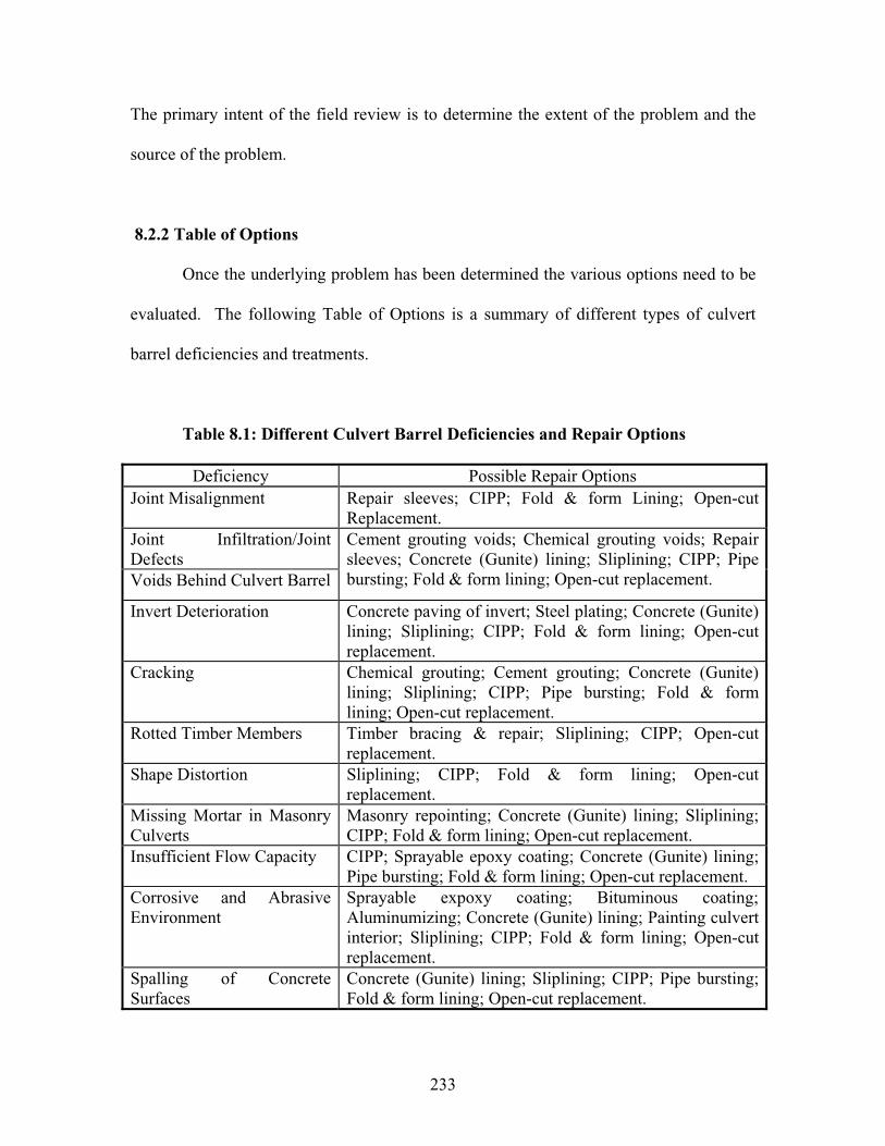
233
The primary intent of the field review is to determine the extent of the problem and the
source of the problem.
8.2.2 Table of Options
Once the underlying problem has been determined the various options need to be
evaluated. The following Table of Options is a summary of different types of culvert
barrel deficiencies and treatments.
Table 8.1: Different Culvert Barrel Deficiencies and Repair Options
Deficiency Possible Repair Options Joint Misalignment Repair sleeves; CIPP; Fold & form Lining; Open-cut
Replacement. Joint Infiltration/Joint DefectsVoids Behind Culvert Barrel
Cement grouting voids; Chemical grouting voids; Repair sleeves; Concrete (Gunite) lining; Sliplining; CIPP; Pipe bursting; Fold & form lining; Open-cut replacement.
Invert Deterioration Concrete paving of invert; Steel plating; Concrete (Gunite) lining; Sliplining; CIPP; Fold & form lining; Open-cut replacement.
Cracking Chemical grouting; Cement grouting; Concrete (Gunite) lining; Sliplining; CIPP; Pipe bursting; Fold & form lining; Open-cut replacement.
Rotted Timber Members Timber bracing & repair; Sliplining; CIPP; Open-cut replacement.
Shape Distortion Sliplining; CIPP; Fold & form lining; Open-cut replacement.
Missing Mortar in Masonry Culverts
Masonry repointing; Concrete (Gunite) lining; Sliplining; CIPP; Fold & form lining; Open-cut replacement.
Insufficient Flow Capacity CIPP; Sprayable epoxy coating; Concrete (Gunite) lining; Pipe bursting; Fold & form lining; Open-cut replacement.
Corrosive and Abrasive Environment
Sprayable expoxy coating; Bituminous coating; Aluminumizing; Concrete (Gunite) lining; Painting culvert interior; Sliplining; CIPP; Fold & form lining; Open-cut replacement.
Spalling of Concrete Surfaces
Concrete (Gunite) lining; Sliplining; CIPP; Pipe bursting; Fold & form lining; Open-cut replacement.

234
The
cos
t of
dif
fere
nt t
reat
men
ts i
s al
so i
mpo
rtan
t in
det
erm
inin
g th
e be
st u
se o
f re
sour
ces.
The
fol
low
ing
char
t is
bas
ed o
n
abou
t 20
0 pr
ojec
ts f
rom
mun
icip
aliti
es a
nd is
fro
m a
n ar
ticle
in
Tre
nchl
ess
Tec
hnol
ogy ,
Cos
ts o
f Tr
ench
less
Pro
ject
s, A
pril
2003
, by
Jack
Q. Z
hao
and
Bal
vant
B. R
ajan
i. I
t can
be
used
as
a gu
ide
in e
valu
atin
g co
sts
of v
ario
us o
ptio
ns.
Fig
ure
8.1:
Ave
rage
Cos
t P
er F
oot
for
Var
ious
Tre
nchl
ess
Tec
hnol
ogie
s

235
8.3 CULVERT BARREL MAINTENANCE AND REPLACEMENT
TECHNIQUES
For purposes of this document, replacement includes any treatments that create a
structurally new barrel. Maintenance and rehabilitation includes treatments to the barrel
that may add structural integrity, but does not replace the structural need of the original
barrel.
8.3.1 Culvert Barrel Maintenance and Rehabilitation Techniques
Any good infrastructure program requires a balance between funds available and
needs. To preserve the system in the best overall condition a combination of
maintenance and replacement projects is necessary. Due to financial constraints, it will
not always be possible to replace culverts even when justified; it may be necessary to
extend the life through rehabilitation and maintenance. At other times, it will be fiscally
responsible to extend the service life of a culvert through appropriately selected
maintenance and rehabilitation treatments. This section is committed to highlighting
options for the maintenance and rehabilitation of the existing culvert system.
8.3.1.1 Invert Replacement and Repair
Inverts of culverts deteriorate for various reasons. Primarily they deteriorate
because of abrasion or corrosion. Abrasive forces are created from the bedload moving
through the culvert. According to the Federal Highway Administration, Culvert Repair
Practices Manual stream velocities based on 2-5 year storms should be checked.
Velocities greater than 15 ft/sec (4.5 m/sec) are undesirable, and the repair should include

236
a means to dissipate the flow. Flows below 5 ft/sec (1.5 m/sec) are good. The bedload
should be considered also. The size, shape, and hardness will affect the rate of
deterioration. This is especially important to consider in the mid range of velocities (5
ft/sec – 15 ft/sec or 1.5 m/sec sec – 4.5 m/sec). The hardness of the natural streambed
material should be compared to the hardness of the invert material. This should be
considered in any concrete mix designs that are intended to protect the invert.
Corrosive forces can be caused by an imbalance in ph levels, soil resistivity,
sulfate levels or industrial runoff. In Ohio, the most significant corrosive factor is ph
level. Ph levels between 5.5 and 8.5 are considered neutral. Ph levels less than 5.5 are
acidic and are frequently found in mine areas, as shown below.
Figure 8.2: Typical Ph Values Found in Ohio
From Ohio Culvert Durability Study, 1982 by J. Hurd, D. Meacham and W. Shisler
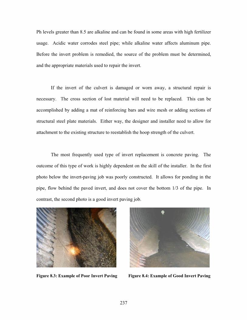
237
Ph levels greater than 8.5 are alkaline and can be found in some areas with high fertilizer
usage. Acidic water corrodes steel pipe; while alkaline water affects aluminum pipe.
Before the invert problem is remedied, the source of the problem must be determined,
and the appropriate materials used to repair the invert.
If the invert of the culvert is damaged or worn away, a structural repair is
necessary. The cross section of lost material will need to be replaced. This can be
accomplished by adding a mat of reinforcing bars and wire mesh or adding sections of
structural steel plate materials. Either way, the designer and installer need to allow for
attachment to the existing structure to reestablish the hoop strength of the culvert.
The most frequently used type of invert replacement is concrete paving. The
outcome of this type of work is highly dependent on the skill of the installer. In the first
photo below the invert-paving job was poorly constructed. It allows for ponding in the
pipe, flow behind the paved invert, and does not cover the bottom 1/3 of the pipe. In
contrast, the second photo is a good invert paving job.
Figure 8.3: Example of Poor Invert Paving Figure 8.4: Example of Good Invert Paving
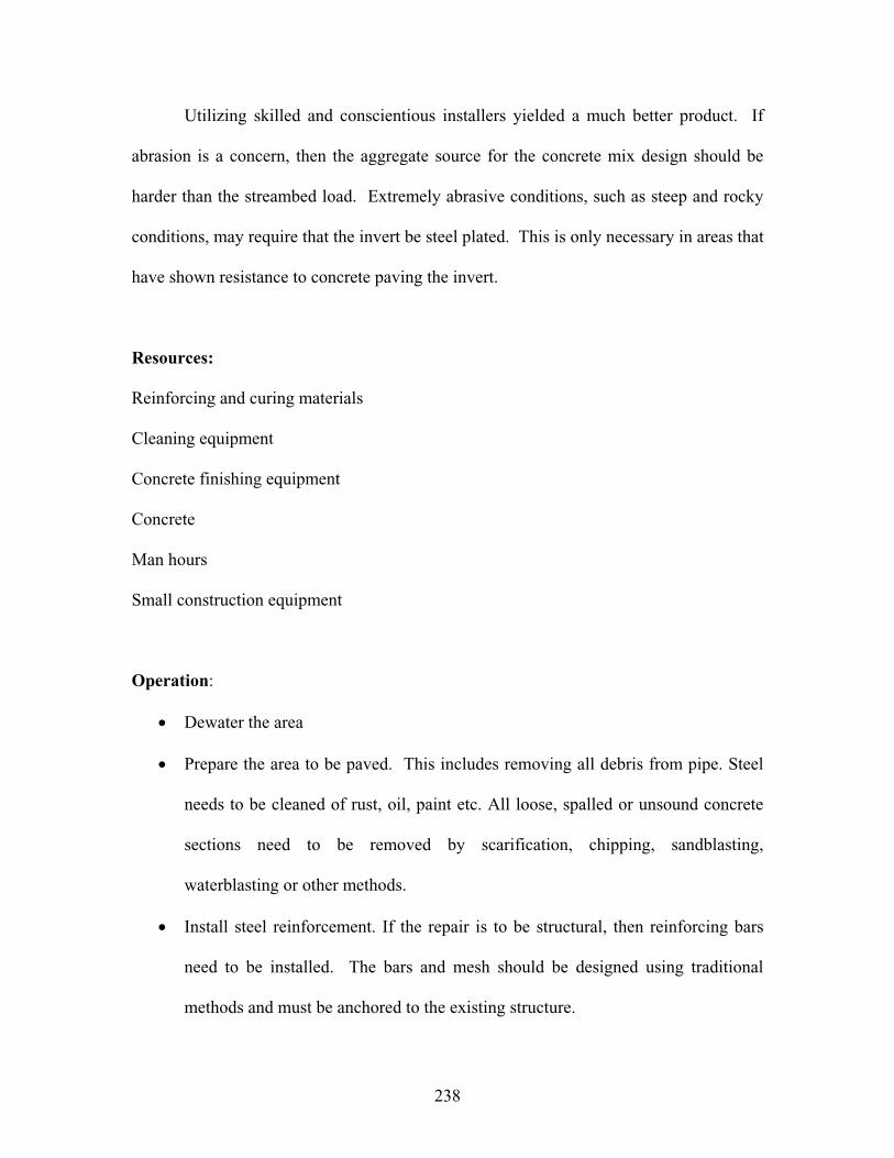
238
Utilizing skilled and conscientious installers yielded a much better product. If
abrasion is a concern, then the aggregate source for the concrete mix design should be
harder than the streambed load. Extremely abrasive conditions, such as steep and rocky
conditions, may require that the invert be steel plated. This is only necessary in areas that
have shown resistance to concrete paving the invert.
Resources:
Reinforcing and curing materials
Cleaning equipment
Concrete finishing equipment
Concrete
Man hours
Small construction equipment
Operation:
Dewater the area
Prepare the area to be paved. This includes removing all debris from pipe. Steel
needs to be cleaned of rust, oil, paint etc. All loose, spalled or unsound concrete
sections need to be removed by scarification, chipping, sandblasting,
waterblasting or other methods.
Install steel reinforcement. If the repair is to be structural, then reinforcing bars
need to be installed. The bars and mesh should be designed using traditional
methods and must be anchored to the existing structure.

239
Moisten earth, concrete and masonry structures. This needs to be done to avoid
water absorption from the concrete mix. Standing water should not be allowed.
Apply the concrete. The mix will need to be tested, delivered to the jobsite, and
transported to the pipe. Mix design should limit shrinking. Care must be taken to
allow the concrete to have adequate cover both above and below the reinforcing.
Cure the concrete. This can be done with a curing compound or keeping the area
damp through sprinkling or wet mats. Caution is needed when placing the curing
materials to not disrupt the reinforcing.
Clean up the jobsite.
Another option for invert repair is coating. Coating the surface extends the life of the
culvert. Frequently coatings only add 1-2 years to service life. It is important to get a
good bond between the original material and coating. Section 8.3.2.1 Material Selections
includes various options for coating pipes. The most common is bituminous coating or
painting the interior of the pipe. These choices should be used in areas with acidic
conditions and low velocities and non-abrasive bedload. The cost will not be returned if
the velocity or bedload wears off the coating in a short time period. Ideally the velocities
should be below 5 ft/sec (1.5 m/sec) and the bedload should be soft, predominately silts
and soils. If the bedload is granular, particularly if it is angular this treatment should be
avoided.
Other options of coatings are available for more abrasive conditions. For example,
Raven has a sprayable epoxy coating called AquataPoxy A-6. Other manufactures have
240
similar products that have been used to reline manholes. It provides a very smooth
surface and is highly resistive to corrosive environments. It requires man entry, but can
be used for any size or shape, as well as at connecting cross pipes.
8.3.1.2 Masonry Repointing
Masonry culverts are in place across the state. Many have been extended with
concrete structures. The concrete structures are in good condition, but the masonry
sections are beginning to deteriorate, especially the grout areas. If these areas can be
repaired prior to movement of the masonry units themselves, the service life of the
culvert can be greatly increased. Once backfill material can be seen piping through the
joints the success rate decreases. If replacement stones are used they must be sound and
not have any defects. Most frequently a nearly zero slump concrete mortar mix is used,
but other types of grout material are also available. See section 8.3.1.4, Joint sealing, for
other possible grouts.
Many of these masonry culverts may be considered historic and may require
specific environmental coordination. In general, if the culvert is being repaired and not
changed significantly it may not be difficult to clear environmentally. Nonetheless,
masonry culverts, particularly arch style, should be coordinated well in advance with
environmental professionals before work begins. Other possible options to consider for
masonry structures are sliplining (see Section 8.3.2.2) and cured in place pipe (see
Section 8.3.2.3).
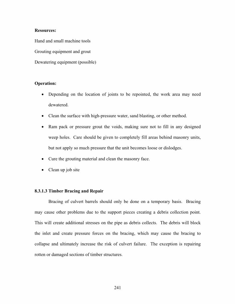
241
Resources:
Hand and small machine tools
Grouting equipment and grout
Dewatering equipment (possible)
Operation:
Depending on the location of joints to be repointed, the work area may need
dewatered.
Clean the surface with high-pressure water, sand blasting, or other method.
Ram pack or pressure grout the voids, making sure not to fill in any designed
weep holes. Care should be given to completely fill areas behind masonry units,
but not apply so much pressure that the unit becomes loose or dislodges.
Cure the grouting material and clean the masonry face.
Clean up job site
8.3.1.3 Timber Bracing and Repair
Bracing of culvert barrels should only be done on a temporary basis. Bracing
may cause other problems due to the support pieces creating a debris collection point.
This will create additional stresses on the pipe as debris collects. The debris will block
the inlet and create pressure forces on the bracing, which may cause the bracing to
collapse and ultimately increase the risk of culvert failure. The exception is repairing
rotten or damaged sections of timber structures.
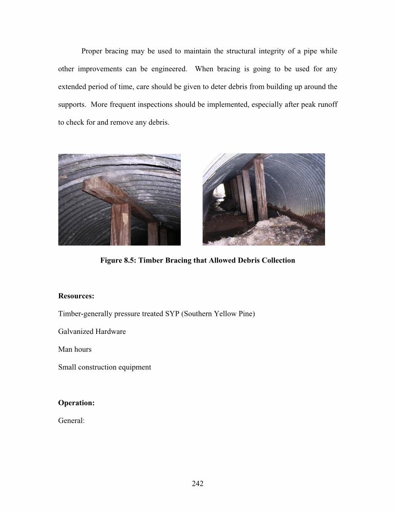
242
Proper bracing may be used to maintain the structural integrity of a pipe while
other improvements can be engineered. When bracing is going to be used for any
extended period of time, care should be given to deter debris from building up around the
supports. More frequent inspections should be implemented, especially after peak runoff
to check for and remove any debris.
Figure 8.5: Timber Bracing that Allowed Debris Collection
Resources:
Timber-generally pressure treated SYP (Southern Yellow Pine)
Galvanized Hardware
Man hours
Small construction equipment
Operation:
General:
243
When adding timber bracing, make sure to span the critical points and provide lateral
support for weak areas. Do not put point loads on weak or critical areas. Look for areas
that may be ‘next’ to take on the stresses and consider supporting these areas also.
For Rotted Area:
Replace the rotted area plus an additional two-foot along the grain. It is also suggested
that a barrier be placed between the new segment and the old segment to reduce the
chance of spreading rot and fungi. Barrier can be tarpaper, roof shingles, etc.
For Weak or Overloaded Areas:
Add a sister member and include a barrier layer. DO NOT install metal caps, as this
provides a channel for water to filter directly onto the repaired area and increases the
chance of additional rot damage.
8.3.1.4 Crack and Joint Sealing
Joints commonly become separated due to shifts in backfill. This can be caused
during the original installation process or over time. Backfill is frequently more difficult
to compact during part width construction, and this may lead to unstable backfill, and
hence, separated joints. This can affect all types of pipe material. Uneven bedding,
earthquakes, and frost heave can also cause joint separation. Separated joints are not a
large concern if they have stabilized and backfill material is not ‘seeping’ into the pipe.
‘Seeping’ backfill can cause piping, which can lead to pipe failures if left unattended.
Measurements should be taken over time to determine if the joints are moving or if they
244
have stabilized. If backfill is infiltrating into the pipe, then the joint condition is more
significant. There are several different types of fixes that can be used for sealing joints.
The most frequent maintenance treatment is grouting. Several types of grouting
materials are available. The most common grout material is Portland cement based with
or without admixtures. This allows some structural improvement, especially if fibers and
reinforcing is included. It can fill voids completely and is the most economical grout
material.
Chemical grouting with polyurethane foam can be used for non-structural joint
repairs. It should not be used on longitudinal or circumferential cracks. It is applied in a
foam, expands to fill the void, and stops infiltration. When it has cured it is hard but
slightly flexible. It is suited well to wet joints and areas that are inlet controlled or below
the water table. If the water is running from the joint the void can be filled first with
grout soaked, oil-free oakum and then injected with grout. Care is needed so excessive
pressure is not exerted on the pipe during the expansion process. This type of chemical
grouting is generally used for minor voids caused by leaking or open joints. Installation
should be according to the manufacture specifications.
Another chemical grouting material is urethane gel. It is less expensive than
polyurethane foams, but is more difficult to install consistently since it reacts with any
water in the surrounding soils. This leads to the necessity of having a knowledgeable
contractor that can adjust the mixture on demand.
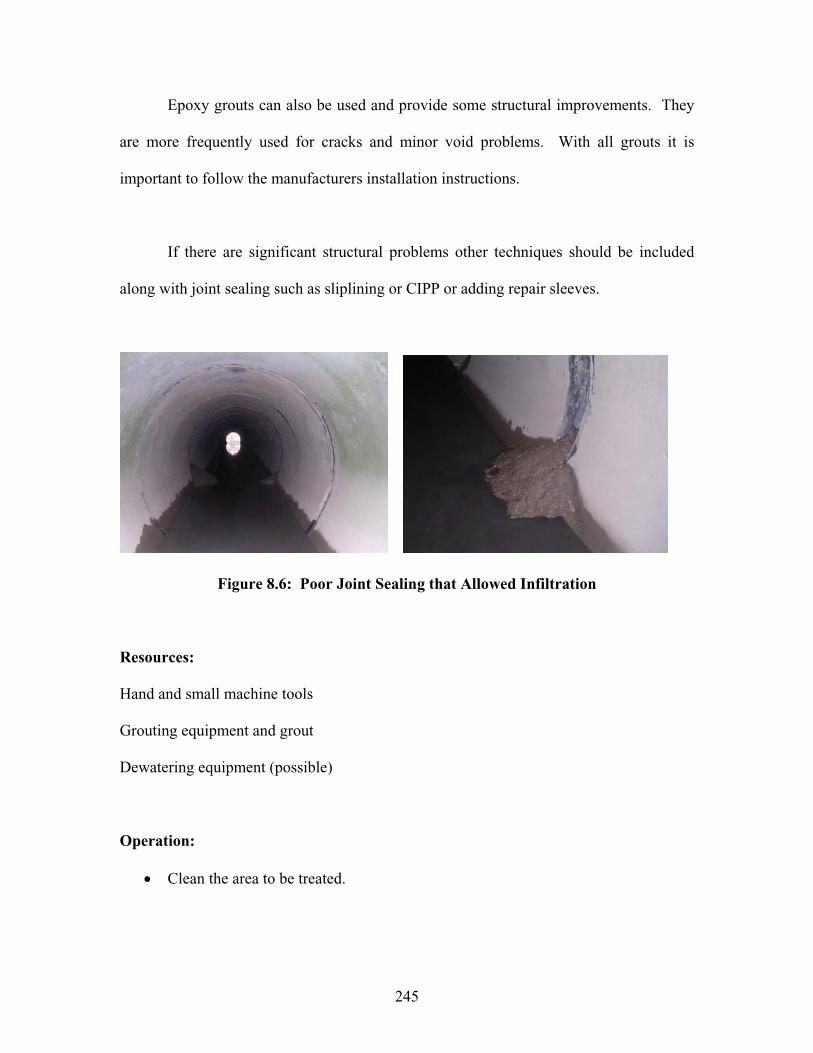
245
Epoxy grouts can also be used and provide some structural improvements. They
are more frequently used for cracks and minor void problems. With all grouts it is
important to follow the manufacturers installation instructions.
If there are significant structural problems other techniques should be included
along with joint sealing such as sliplining or CIPP or adding repair sleeves.
Figure 8.6: Poor Joint Sealing that Allowed Infiltration
Resources:
Hand and small machine tools
Grouting equipment and grout
Dewatering equipment (possible)
Operation:
Clean the area to be treated.
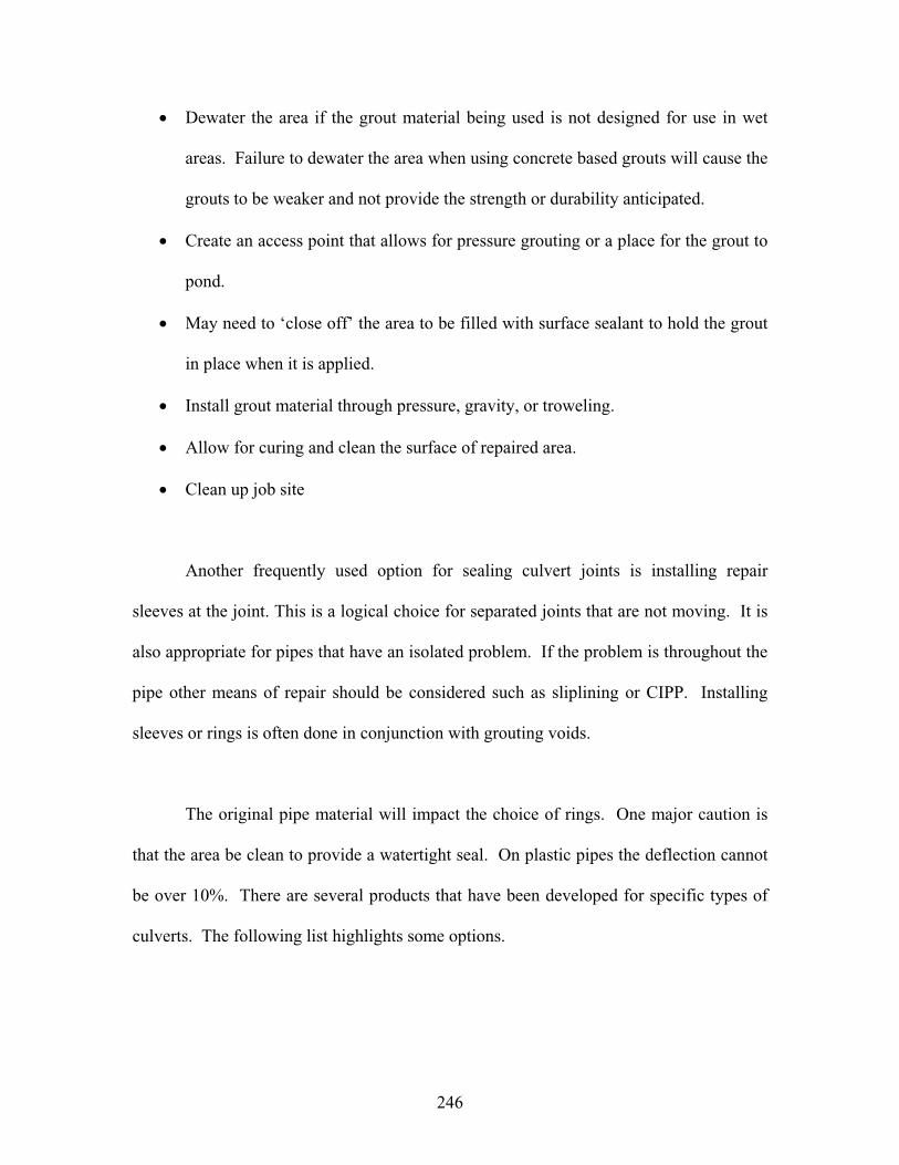
246
Dewater the area if the grout material being used is not designed for use in wet
areas. Failure to dewater the area when using concrete based grouts will cause the
grouts to be weaker and not provide the strength or durability anticipated.
Create an access point that allows for pressure grouting or a place for the grout to
pond.
May need to ‘close off’ the area to be filled with surface sealant to hold the grout
in place when it is applied.
Install grout material through pressure, gravity, or troweling.
Allow for curing and clean the surface of repaired area.
Clean up job site
Another frequently used option for sealing culvert joints is installing repair
sleeves at the joint. This is a logical choice for separated joints that are not moving. It is
also appropriate for pipes that have an isolated problem. If the problem is throughout the
pipe other means of repair should be considered such as sliplining or CIPP. Installing
sleeves or rings is often done in conjunction with grouting voids.
The original pipe material will impact the choice of rings. One major caution is
that the area be clean to provide a watertight seal. On plastic pipes the deflection cannot
be over 10%. There are several products that have been developed for specific types of
culverts. The following list highlights some options.
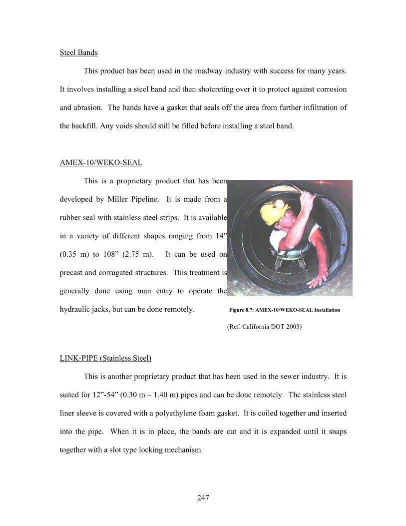
247
Steel Bands
This product has been used in the roadway industry with success for many years.
It involves installing a steel band and then shotcreting over it to protect against corrosion
and abrasion. The bands have a gasket that seals off the area from further infiltration of
the backfill. Any voids should still be filled before installing a steel band.
AMEX-10/WEKO-SEAL
This is a proprietary product that has been
developed by Miller Pipeline. It is made from a
rubber seal with stainless steel strips. It is available
in a variety of different shapes ranging from 14”
(0.35 m) to 108” (2.75 m). It can be used on
precast and corrugated structures. This treatment is
generally done using man entry to operate the
hydraulic jacks, but can be done remotely. Figure 8.7: AMEX-10/WEKO-SEAL Installation
(Ref. California DOT 2003)
LINK-PIPE (Stainless Steel)
This is another proprietary product that has been used in the sewer industry. It is
suited for 12”-54” (0.30 m – 1.40 m) pipes and can be done remotely. The stainless steel
liner sleeve is covered with a polyethylene foam gasket. It is coiled together and inserted
into the pipe. When it is in place, the bands are cut and it is expanded until it snaps
together with a slot type locking mechanism.
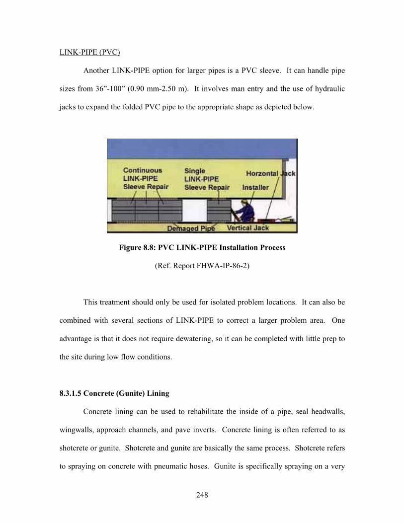
248
LINK-PIPE (PVC)
Another LINK-PIPE option for larger pipes is a PVC sleeve. It can handle pipe
sizes from 36”-100” (0.90 mm-2.50 m). It involves man entry and the use of hydraulic
jacks to expand the folded PVC pipe to the appropriate shape as depicted below.
Figure 8.8: PVC LINK-PIPE Installation Process
(Ref. Report FHWA-IP-86-2)
This treatment should only be used for isolated problem locations. It can also be
combined with several sections of LINK-PIPE to correct a larger problem area. One
advantage is that it does not require dewatering, so it can be completed with little prep to
the site during low flow conditions.
8.3.1.5 Concrete (Gunite) Lining
Concrete lining can be used to rehabilitate the inside of a pipe, seal headwalls,
wingwalls, approach channels, and pave inverts. Concrete lining is often referred to as
shotcrete or gunite. Shotcrete and gunite are basically the same process. Shotcrete refers
to spraying on concrete with pneumatic hoses. Gunite is specifically spraying on a very
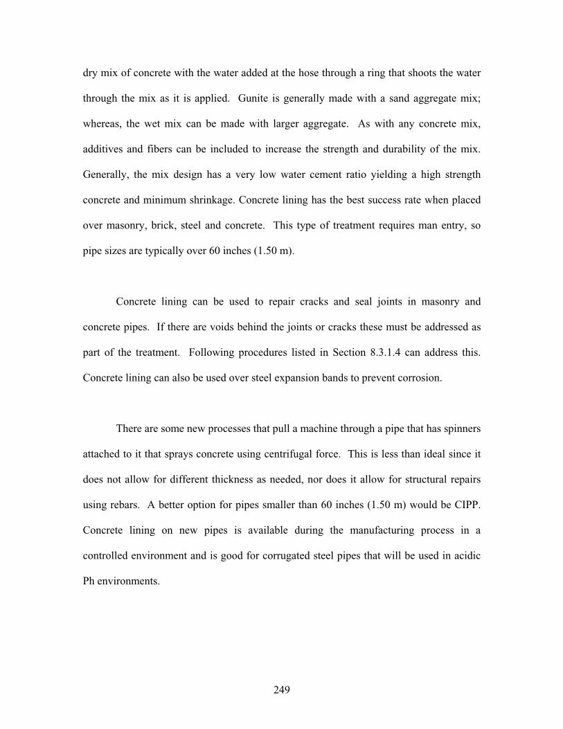
249
dry mix of concrete with the water added at the hose through a ring that shoots the water
through the mix as it is applied. Gunite is generally made with a sand aggregate mix;
whereas, the wet mix can be made with larger aggregate. As with any concrete mix,
additives and fibers can be included to increase the strength and durability of the mix.
Generally, the mix design has a very low water cement ratio yielding a high strength
concrete and minimum shrinkage. Concrete lining has the best success rate when placed
over masonry, brick, steel and concrete. This type of treatment requires man entry, so
pipe sizes are typically over 60 inches (1.50 m).
Concrete lining can be used to repair cracks and seal joints in masonry and
concrete pipes. If there are voids behind the joints or cracks these must be addressed as
part of the treatment. Following procedures listed in Section 8.3.1.4 can address this.
Concrete lining can also be used over steel expansion bands to prevent corrosion.
There are some new processes that pull a machine through a pipe that has spinners
attached to it that sprays concrete using centrifugal force. This is less than ideal since it
does not allow for different thickness as needed, nor does it allow for structural repairs
using rebars. A better option for pipes smaller than 60 inches (1.50 m) would be CIPP.
Concrete lining on new pipes is available during the manufacturing process in a
controlled environment and is good for corrugated steel pipes that will be used in acidic
Ph environments.
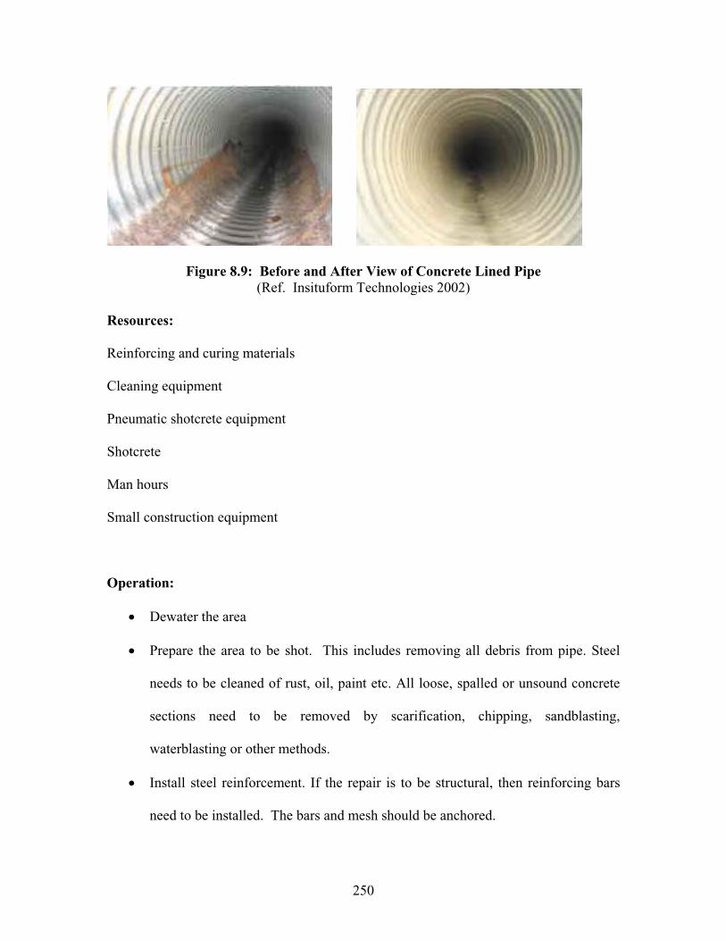
250
Figure 8.9: Before and After View of Concrete Lined Pipe (Ref. Insituform Technologies 2002)
Resources:
Reinforcing and curing materials
Cleaning equipment
Pneumatic shotcrete equipment
Shotcrete
Man hours
Small construction equipment
Operation:
Dewater the area
Prepare the area to be shot. This includes removing all debris from pipe. Steel
needs to be cleaned of rust, oil, paint etc. All loose, spalled or unsound concrete
sections need to be removed by scarification, chipping, sandblasting,
waterblasting or other methods.
Install steel reinforcement. If the repair is to be structural, then reinforcing bars
need to be installed. The bars and mesh should be anchored.
251
Moisten earth, concrete and masonry structures. This needs to be done to avoid
water absorption from the concrete mix. Standing water should not be allowed.
Apply the concrete. The mix will need to be tested, delivered to the jobsite, and
pneumatically transported to the pipe. The operator should apply the mix using
guidelines from the American Concrete Institute (ACI). Specifically, care should
be taken to properly encase the reinforcing and to apply shotcrete with minimal
rebound. Generally this requires that the shotcrete be applied at a 90-degree angle
in a circular motion and filling corners first. Care needs to be taken around
dowels to not create a ‘sand pocket’ behind the bars.
Cure the concrete. This can be done with a curing compound or keeping the area
damp through sprinkling or wet mats. Caution is needed when placing the curing
materials to not disrupt the reinforcing.
Clean up job site
8.3.2 Culvert Barrel Replacement Techniques
Culvert barrel replacement techniques are options that add structural integrity or
completely replace the barrel of the culvert. This section is very diverse and includes
techniques that have been used frequently for storm water systems and highway culverts.
Some options, such as tunneling and boring, are expensive and will only be justified
under specific conditions. Other options are very cost effective and should be considered
frequently for structurally deficient culverts.
252
8.3.2.1 Material Selection
Material selection is a part of choosing the best replacement technique. Every
material type has specific properties that will allow it to function in various
environments. The following Table of Materials summarizes the sizes, specification
references and capabilities for several culvert materials. In selecting the material type,
key factors are abrasion and corrosive resistance. If the stream velocity is doubled, the
abrasive power of the underlying bedload quadruples.
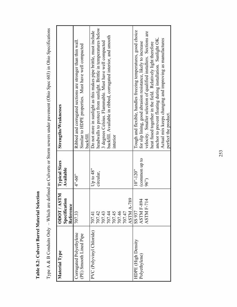
253
Tab
le 8
.2:
Cul
vert
Bar
rel M
ater
ial S
elec
tion
Typ
e A
& B
Con
duits
Onl
y –
Whi
ch a
re d
efin
ed a
s C
ulve
rts
or S
torm
sew
ers
unde
r pa
vem
ent (
Ohi
o Sp
ec 6
03)
in O
hio
Spec
ific
atio
ns
Mat
eria
l Typ
e O
DO
T /
AST
M
Spec
ific
atio
n R
efer
ence
Typ
ical
Siz
es
Ava
ilabl
eSt
reng
ths/
Wea
knes
ses
Cor
ruga
ted
Poly
ethy
lene
(P
E)
Smoo
th L
ined
Pip
e 70
7.33
4”
-60”
R
ibbe
d an
d co
rrug
ated
sec
tions
are
str
onge
r th
an th
in w
all.
Sim
ilar
to H
DPE
pro
pert
ies.
Mus
t hav
e w
ell c
ompa
cted
ba
ckfi
ll.
PVC
(Po
lyvi
nyl C
hlor
ide)
70
7.41
70
7.42
707.
4370
7.44
707.
4570
7.46
707.
47A
STM
A-7
89
Up
to 4
8”
circ
ular
, D
o no
t sto
re in
sun
light
as
this
mak
es p
ipe
britt
le, m
ust i
nclu
de
head
wal
ls to
pro
tect
fro
m s
unlig
ht. B
rittl
e in
tem
pera
ture
s be
low
3
degr
ees
Cel
sius
. Fla
mm
able
. Mus
t hav
e w
ell c
ompa
cted
ba
ckfi
ll. A
vaila
ble
in r
ibbe
d, c
orru
gate
d in
teri
or, a
nd s
moo
th
inte
rior
HD
PE (
Hig
h D
ensi
ty
Poly
ethy
lene
)
SS 9
37
AST
M F
-894
A
STM
F-7
14
10”-
120”
(com
mon
up
to
96”)
Tou
gh a
nd f
lexi
ble,
han
dles
fre
ezin
g te
mpe
ratu
res,
goo
d ch
oice
fo
r sl
ip li
ning
, goo
d ab
rasi
on r
esis
tanc
e, li
kely
to in
crea
se
velo
city
. Sm
alle
r se
lect
ion
of q
ualif
ied
inst
alle
rs.
Sect
ions
are
he
at f
used
toge
ther
in th
e fi
eld.
Rel
ativ
ely
light
ther
efor
e an
chor
to p
reve
nt f
loat
ing
duri
ng in
stal
latio
n. S
unlig
ht O
K.
Act
ual m
ix k
eeps
cha
ngin
g an
d im
prov
ing
as m
anuf
actu
res
perf
ect t
he p
rodu
ct.

254
Mat
eria
l Typ
e O
DO
T /
AST
M
Spec
ific
atio
n R
efer
ence
Typ
ical
Siz
es
Ava
ilabl
eSt
reng
ths/
Wea
knes
ses
Prec
ast R
einf
orce
d C
oncr
ete
706.
0570
6.05
170
6.05
2A
STM
C-7
6
Ava
ilabl
e in
bo
xes,
3-s
ided
bo
xes
and
arch
es
(up
to 4
0’ s
pan)
, 4-
side
d (u
p to
20’
sp
an),
cir
cula
r (u
p to
144
” di
a.),
an
d el
liptic
al (
up
to 1
44”
span
).
Ava
ilabl
e in
a w
ide
rang
e of
siz
es a
nd s
hape
s. P
redi
ctab
le
cons
truc
tion
met
hods
, mus
t hav
e ex
peri
ence
d op
erat
or to
‘se
t’
pipe
in p
lace
. Sho
rter
con
stru
ctio
n tim
es th
an c
ast i
n pl
ace
proj
ects
. Mos
t com
mon
pro
blem
s ar
e jo
int d
efec
ts a
nd s
ectio
n dr
op o
ff.
In h
igh
sulf
ur c
onte
nt a
reas
, suc
h as
min
ing
area
s,
cem
ent m
ay d
isin
tegr
ate
from
the
conc
rete
, cre
atin
g sp
allin
g an
d ex
posi
ng th
e re
info
rcin
g. B
est f
or p
h ra
nges
fro
m 6
-10.
If
pH is
le
ss th
an 5
then
nee
d to
pro
tect
.
Cor
ruga
ted
Alu
min
um
Allo
y70
7.21
707.
2270
7.23
707.
2470
7.25
Cir
cula
r (6
”-12
0”)
stru
ctur
al
plat
e (6
0”-
252”
roun
d an
d up
to 3
0’ a
rch,
bo
x), s
pira
l rib
Not
goo
d in
hig
h PH
are
as th
at h
ave
fert
ilize
r ru
noff
, poo
r ab
rasi
on r
esis
tanc
e, g
ood
resi
stan
ce to
min
e w
ater
(lo
w P
H),
se
nsiti
ve to
poo
r ba
ckfi
ll, lo
w c
over
. M
ore
flex
ible
than
ste
el.
Ava
ilabl
e in
wid
e ra
nge
of s
izes
and
sha
pes.
Bes
t for
pH
ran
ges
betw
een
4-9
and
velo
citie
s le
ss th
an 1
5 ft
/sec
(4.
5 m
/sec
).
Rei
nfor
ced
Con
cret
eN
on-R
einf
orce
d C
oncr
ete
706.
0270
6.04
706.
01A
STM
C-7
6
12”-
144”
cir
cula
r
e
llipt
ical
A
vaila
ble
in a
wid
e ra
nge
of s
izes
and
sha
pes.
Pre
dict
able
co
nstr
uctio
n m
etho
ds, m
ust h
ave
expe
rien
ced
oper
ator
to ‘
set’
pi
pe in
pla
ce. S
hort
er c
onst
ruct
ion
times
than
cas
t in
plac
e pr
ojec
ts. M
ost c
omm
on p
robl
ems
are
join
t def
ects
and
sec
tion
drop
off
. In
hig
h su
lfur
con
tent
are
as, s
uch
as m
inin
g ar
eas,
ce
men
t may
dis
inte
grat
e fr
om th
e co
ncre
te, c
reat
ing
spal
ling
and
expo
sing
the
rein
forc
ing.
Bes
t for
ph
rang
es f
rom
6-1
0. I
f pH
is
less
than
5 th
en n
eed
to p
rote
ct.

255
Mat
eria
l Typ
e O
DO
T /
AST
M
Spec
ific
atio
n R
efer
ence
Typ
ical
Siz
es
Ava
ilabl
eSt
reng
ths/
Wea
knes
ses
Bitu
min
ous
Coa
ted/
Lin
ed
Poly
mer
ized
asp
halt
AST
M A
-849
A
STM
A-7
42
AA
SHT
O M
-190
1.25
mils
m
inim
um
Gen
eral
ly p
ut o
n co
rrug
ated
ste
el p
ipes
. Can
wea
r aw
ay in
few
ye
ars,
fas
ter
in a
bras
ive
envi
ronm
ents
. C
are
need
ed d
urin
g tr
ansp
ort a
nd in
stal
latio
n to
not
dam
age
coat
ing.
Poo
r fo
r ab
rasi
on a
nd s
unlig
ht c
ondi
tions
. Pol
ymer
ized
asp
halt
bette
r in
fi
sh s
ensi
tive
area
s.
Epo
xy C
oate
d 70
6.03
A
ny s
ize
Gen
eral
ly p
ut o
n co
ncre
te p
ipes
in a
ggre
ssiv
e ch
emic
al
envi
ronm
ents
. Pol
yam
ide-
cure
d, tw
o co
mpo
nent
coa
l tar
epo
xy
coat
ing.
App
lied
duri
ng m
anuf
actu
ring
pro
cess
, det
ers
the
brea
kdow
n of
the
cem
ent i
n th
e co
ncre
te, n
ot v
ery
effe
ctiv
e in
hi
gh v
eloc
ity o
r ab
rasi
ve b
edlo
ad c
ondi
tions
. C
oncr
ete/
Mor
tar
Coa
ted
(Lin
ed)
707.
11A
STM
A-8
49
24”-
120”
G
ener
ally
put
on
corr
ugat
ed s
teel
pip
es in
are
as th
at n
eed
both
co
rros
ion
and
abra
sion
pro
tect
ion.
Car
e m
ust b
e ta
ken
to g
et
good
bon
d be
twee
n th
e m
etal
and
con
cret
e. M
ake
sure
bar
s ar
e no
t exp
osed
. A
lum
iniz
ed C
ladd
ing
707.
01
707.
0270
7.12
C
oat s
teel
to p
rote
ct a
gain
st c
orro
sion
. Wor
ks w
ell f
or P
H in
the
rang
e of
5-9
. Po
or c
hoic
e in
abr
asiv
e pr
one
area
s. A
ccep
tabl
e fo
r ve
loci
ties
belo
w 1
5 ft
/sec
(4.
5m/s
ec)
Met
allic
coa
ted
Cor
ruga
ted
Stee
l 70
7.01
707.
02C
ircu
lar
(6”-
26’)
, el
liptic
al (
4’-2
1’),
ar
ches
(va
riou
s sh
apes
up
to 5
0’),
bo
xes
(up
to 2
6’)
Mos
t oft
en c
oate
d w
ith z
inc
allo
y. C
an b
e co
ated
with
oth
er
mat
eria
ls (
See
Coa
tings
). ¼
”-1”
dee
p co
rrug
atio
ns ty
pica
l. G
ener
ally
com
es in
gal
vani
zed
stee
l tha
t han
dles
PH
leve
ls f
rom
6-
10 a
dequ
atel
y. A
reas
whe
re th
e ga
lvan
izin
g is
dam
aged
sh
ould
be
pain
ted
with
a z
inc
rich
pai
nt a
s pa
rt o
f th
e re
pair
. M
ost c
omm
on p
robl
ems
are
inve
rt d
eter
iora
tion,
and
join
t se
para
tion.

256
Mat
eria
l Typ
e O
DO
T /
AST
M
Spec
ific
atio
n R
efer
ence
Typ
ical
Siz
es
Ava
ilabl
eSt
reng
ths/
Wea
knes
ses
Stru
ctur
al P
late
C
orru
gate
d St
eel
707.
03
Gen
eral
ly
circ
ular
or
arch
5’
to 2
6’ s
pan.
So
me
boxe
s
Mos
t typ
ical
ly u
sed
for
low
cle
aran
ce, l
arge
wat
erw
ay
open
ings
. Cor
ruga
tions
2”-
5” d
eep
typi
cal,
Vitr
ifie
d C
lay
706.
08
AST
M C
700
V
arie
s M
ust s
peci
fy E
xtra
Str
engt
h on
ly f
or c
ulve
rts,
res
ista
nt to
ab
rasi
on a
nd c
orro
sion
, wea
ker
than
oth
er o
ptio
ns, t
ende
ncy
to
crac
kC
ast I
ron
V
arie
s G
ener
ally
not
use
d in
new
inst
alla
tions
, hea
vy, v
ery
britt
le,
crac
ks e
asily
. If
use
d m
ust h
ave
good
bed
ding
. V
ery
good
ag
ains
t cor
rosi
on.
FRP
(Fib
ergl
ass
Rei
nfor
ced
Pipe
)
8”-1
44”
Com
posi
te p
ipe,
Man
ning
s n
= 0
.009
, car
ry s
truc
tura
l loa
ding
, hi
gh r
esis
tanc
e to
ext
rem
e ch
emic
al e
nvir
onm
ents
FR
PC (
Fibe
r R
einf
orce
d Po
lym
er C
oncr
ete)
18”-
96”
Exp
ensi
ve, c
omm
on b
rand
is H
OB
AS,
str
ong,
res
ista
nt to
co
rros
ion,
long
life
257
8.3.2.2 Sliplining
Sliplining is simply inserting a new pipe into the existing pipe and filling the annular
space between the two pipes. This is one of the most versatile and beneficial options in
culvert barrel replacement. When a pipe is properly sliplined with a new pipe, it
functions close to a new installation, sometimes better. Sliplining can be used in many
cases where the existing barrel has deteriorated. Its largest advantage is that the project
can be completed with little to no impact on the traveled roadway. In addition, the cost is
significantly less, especially if the culvert is under deep fill. If the host pipe has
deformed in shape, a complete survey must be done to determine the possible sizes
available for the new pipe. Frequently, a smaller smooth wall pipe will meet the
hydraulic needs of the culvert. Care should be given to check the anticipated velocities
from a smooth wall pipe as some form of velocity dissipaters, such as riprap may also be
warranted. When lining the pipe, the corrosive and abrasive forces of the stream should
also be evaluated. Culverts can also be extended during the lining process and thus
roadways can be widened. There are several different styles of liner pipe that can be
utilized. The materials section highlights different choices in pipe materials. The
contractor can also be left with the option of selecting the pipe material, which may lead
to the best price.
Resources:
Liner pipe
Grouting
Work crew

258
Specialized Equipment for the type of specific installation (selected by the contractor)
Operation:
Dewater the work area
Clean the host pipe
Grout any voids behind the host pipe. This must be done to insure that the current
void issues are addressed before the new pipe is inserted. Identify the locations,
then drill and fill. Identification can be done by sounding and looking for
evidence of areas that have infiltrated. Suspect areas can be further investigated.
Care should be exercised to not overfill because of the pressure exerted by the
grout.
Choose appropriate new pipe material. This will determine when and how the
pipe sections are connected. Some will be connected inside the host pipe, such as
precast concrete sections. Corrugated metal sections are generally banded
together outside the pipe. The pipe selection will be based on typical material
applications and available workspace and equipment at the site. Selection should
be based on the capability of inserting the pipe. Some joints cannot be pulled into
place; other joints can be pulled and/or pushed. Corrugated pipes are generally
more difficult to insert, especially into existing corrugated pipe.
Place new pipe in host pipe. There are several different options for getting the
new pipe into the host pipe. It can be pulled or pushed. This is an area that
should not be specified in detail. Contractors may have built specialized
equipment or discovered an innovative way that will work particularly well for

259
the site conditions. The low bidder may be the low bidder because he has come
up with an ingenious way to insert the pipe into the host pipe. However, notes
should be included that ensure the new pipe is put into place without causing
harm to its shape, material, protective coatings, etc. Typically, it is specified to
use guide rails, wood blocking, or other means as approved by the engineer.
Cap off the ends to contain the grout, install grout tubes and possibly extra tubes
to ‘view’ the grouting process.
Grout between the host pipe and new pipe. Care must be taken to not float the
new pipe in the host pipe. Grouting in lifts and/or providing spacers can
accomplish this. The new pipe material must be stronger than the grouting
pressure. Pipes can be fitted with ports on the top that will allow for inspection of
grouting or pressure grouting relief valves. The most frequently used grout
material is Portland cement based mortar or controlled low strength material
(CLSM). Also, the grout, host pipe, and other fill behind the new pipe only needs
to be as strong as well compacted soil for most applications.
Clean up job site.
Within Ohio many culverts have been sliplined. One interesting location is under
the ramp for State Route 668 on Interstate 70. This location was installed in the late
1980’s and includes some interesting design features. Two different size liners were
installed. A larger pipe was used at the inlet end to provide for better hydraulics that was
necessary because of the overall reduction in pipe size. Inside the pipe, the size of the
liner pipe was reduced because of shape distortions in the host pipe. After the liner was

260
inserted and grouted into place the bottom was paved with concrete to increase the flow
capacity and to combat corrosive factors against the steel liner. Today, this pipe is in
very good condition as shown below.
Figure 8.10: Views of 15-Year-Old Sliplined Pipe (Licking County, Ohio)
8.3.2.3 Cured in Place Pipe (CIPP)
Cured in place pipe is a method that allows a new ‘pipe within a pipe’. The pipe
itself is made of a felt tube that is reinforced with fiberglass and coated with plastic. The
felt tube is custom made for each specific site based on size, shape and structural integrity
of the host pipe. The felt tube allows for the absorption of thermosetting resins. The pipe
261
is wetted with resins during the manufacturing process or on site. Most often, they are
applied at the manufacturing plant by a roller and then the pipe is shipped in a
refrigerated truck to the project site for installation.
The CIPP is installed by inserting the pipe into the host pie through an inversion
process. Most frequently, the pipe is inserted into place by water pressure. The pipe is
sealed at one end and water is forced into the open end and ‘turns the pipe right-side out’
as it enters the host pipe. The resin impregnated tube should be snug against the walls of
the host pipe with the plastic layer on the inside diameter. Once the CIPP is in place, the
water is heated causing the thermosetting resin to harden forming a pipe within a pipe
that requires no grouting.
Other options for inverting the pipe include using compressed air and heating the
air into steam to set the thermosetting resins. In addition, some manufacturers offer
CIPPs that can be winched into place and don’t require the inversion process. If this
option is chosen, extreme care must be taken to not contaminate the resins. If the resins
are contaminated, the CIPP may not adhere well to the host pipe.
This process has been used frequently in the sewer industry and has provided
municipalities’ considerable savings. The two predominant manufacturers are Insituform
and Inliner. Both provide design services and can custom design a liner to provide the
size, shape, and strength requirements of a particular site. CIPP can also be used
following tunnel operations to create the pipe walls after the tunneling procedures.
262
When evaluating if cured in place pipe is an appropriate option the following
should be considered. The hydraulic capacity will generally increase, particularly with
larger pipes, due to the smoothness of the polyurethane liner. Also, the size of the pipe
will be decreased slightly, but far less than it would be if a slipliner and grout were
specified. The CIPP requires that a frame be built to ‘feed’ the liner into place. This is
generally done from the roadway surface, close to the end of the culvert. For this reason,
there should be room on the shoulder or roadway to set up the haul truck, water heating
equipment and inversion tubing. The impregnating of resin will be done off site for small
or short sections, but will usually be done on site for larger or long runs. This is due to
the weight and size of handling the larger liners.
CIPP installations can provide structural improvements, but the liner must be
designed with the intent of structural support. Designers should be aware of the need to
be able to insert the felt tube into the host pipe. If the host pipe has deteriorated to a point
where the host pipe cannot be cleaned or made ready for installation, then CIPP is not a
viable choice. In one case, a pipe was scheduled to be rehabilitated using CIPP and the
pipe deteriorated to such a point that it was not safe to prepare the host pipe for insertion
of the liner and a new treatment had to be selected.
A prime application for CIPP would be a metal culvert with a deteriorated invert
and limited hydraulic capacity for the site. An ideal recommendation would be to fix the
invert by filling voids and installing reinforcing and paving the bottom. Then install a
custom designed CIPP. This would defend against the environmental conditions that

263
caused the invert decay and maximize the hydraulic capacity of the pipe. If the pipe was
bituminous coated, it may not be worthwhile to install the CIPP as the host pipe would
need to be epoxy painted prior to CIPP installation. This is necessary to assure that the
CIPP adheres to the host pipe and forms a bond to create a pipe within a pipe.
Environmentally the CIPP process presents pros and cons. The work area will be
primarily from the road or shoulder surface. Minimal space is needed near the culvert
entrance. This makes CIPP a good treatment for environmentally sensitive flora/fauna
habitats. However, care must be used in disposing of the heated (150-200 degree) water
used in the curing process. Another alternative is to use pressurized air to invert the
pipe and then heat the air and allow the steam to cure the pipe. This also requires some
care, as the air must then be allowed to cool and the condensation water trapped and
disposed of properly. This will be a much smaller amount of water and provides
flexibility in the use of this treatment.
Another advantage of CIPP is that the felt tube can be designed for various
shapes, sizes and angles. This is particularly helpful for culverts that have been extended
using different shapes and styles of materials. Furthermore, the CIPP can be designed
with bends up to 90 degrees to allow for turns in the host pipe. Complicated shapes or
angles will require a full survey of the dimensions so the felt tube can be custom designed
to fit the host pipe and allow a smooth interior surface.

264
Figure 8.11: Cured-In-Place Pipe Installation (Ref. Atalah 2003)
Resources:
Specially designed CIPP pipe
Work Zone traffic control
Work crew
Tower (scaffolding) for inversion tube
Water and heaters for inversion and curing process
Refrigerated storage or impregnation system on site
Operation:
Dewater the work area
Clean the host pipe
Make any required structural repairs. Large voids should be filled and deteriorated
inverts should be repaired. Small voids or scaling and rust do not need repaired
unless shifts are evident in the structure. Remember any bituminous coating must
265
either be coated with epoxy paint or the CIPP liner must include a polyethylene
preliner.
Construct tower (scaffolding) to hold liner as it is forced into the pipe. The boiler
and water supply must also be setup, along with the resin impregnation equipment
if required.
Install the liner. The CIPP liner is inside out upon delivery. If it has not been
impregnated with resin this will be done as part of the installation process. One
end of the line will be sealed. The liner is inserted into the host pipe and turned
right side out by forcing water into the open end of the liner.
Cure the liner. Once the liner is in place and forced against the sides of the host
pipe the water is circulated through boilers and the heated water causes the
thermosetting polyester and polyurethane resins to cure. Because heat is what
cures the liner great care should be taken to keep the liner cool until it is in place
and ready to be cured.
Finishing. After the CIPP is in place and cured against the walls of the host pipe
the water may be cooled and released slowly, if environmentally appropriate, or
hauled away for cooling and disposal. The sealed end is cut open and any
appurtenance work is performed.
Clean up job site.
8.3.2.4 Pipe Jacking, Tunneling, Horizontal Directional Drilling
Pipe Jacking, horizontal earth boring and tunneling are all different methods of
installing a new pipe via trenchless technology. This may be necessary to add hydraulic

266
capacity to an area or to provide relief overflow during construction. It may also be used
to install a new pipe to replace an existing pipe. It is not necessary to specify the specific
type of trenchless technology to be used, only the type of pipe and limitations of work
area. The contractor can make the selection of type of installation. The constraints of the
site, and requested features, will narrow the options. The designer should be aware of the
basic operation and limitations of different options.
Pipe Jacking
Pipe Jacking is most frequently done using reinforced concrete pipe, although any
type of pipe that can handle the loads placed on it by the jacking equipment can be used.
Pipe jacking is the most common form of trenchless technology used in highway culvert
installation. The procedure is as shown below:

267
From FHWA-RD-95-089, Culvert Repair Practices Manual, Volume II, May 1995
Figure 8.12: Pipe Jacking Procedure

268
Tunneling
Tunneling is more expensive than pipe jacking and is most often used for large
pipes, from 5’-26’ (1.5 m – 8.0 m). It provides very accurate line and grade control. Any
type of pipe may be installed into the tunnel after it is constructed. Tunneling is
generally used for large-scale projects under deep fill or sensitive conditions. Detailed
soil information is needed for tunneling contractors to bid a contract. The tunnel boring
machine equipment includes five key components: wheel machine with specialized cutter
heads, drum, excavator, and conveyor. The wheel machine rotates heads that are
designed for the type of soils expected. The rotator head excavates the soils and they fall
into the drum. Scoops inside the drum lift the spoils up to the conveyor. Outside the
tunnel, haul equipment needs to be ready to dispose of the spoils. Boring machines can be
operated from inside the tunneling machine or externally.
Figure 8.13: Tunnel Boring Machine Operation (Ref. Insituform Technologies 2002)
Microtunneling
Microtunneling is basically a combination between tunneling and pipe jacking. It
is for pipes in the range of 18”-54” (0.45 m – 1.40 m) and can accommodate a variety of
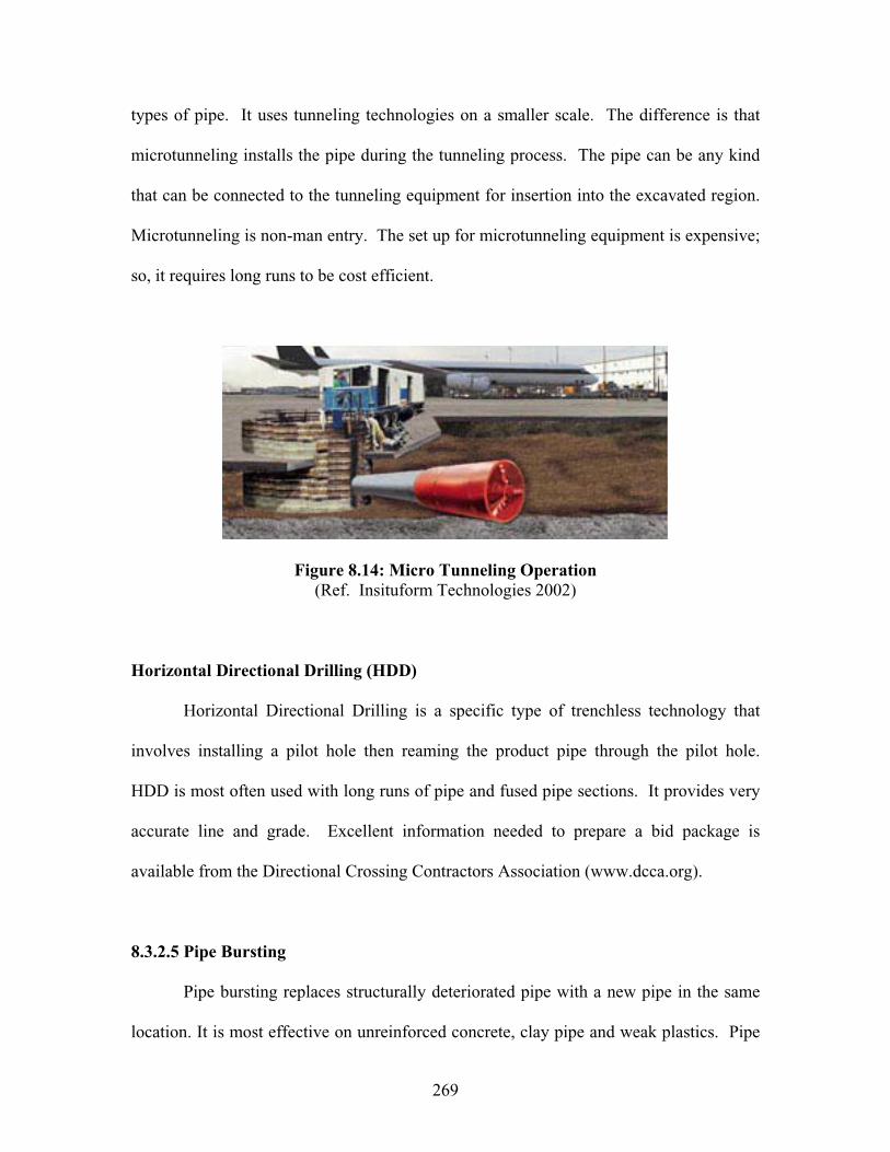
269
types of pipe. It uses tunneling technologies on a smaller scale. The difference is that
microtunneling installs the pipe during the tunneling process. The pipe can be any kind
that can be connected to the tunneling equipment for insertion into the excavated region.
Microtunneling is non-man entry. The set up for microtunneling equipment is expensive;
so, it requires long runs to be cost efficient.
Figure 8.14: Micro Tunneling Operation (Ref. Insituform Technologies 2002)
Horizontal Directional Drilling (HDD)
Horizontal Directional Drilling is a specific type of trenchless technology that
involves installing a pilot hole then reaming the product pipe through the pilot hole.
HDD is most often used with long runs of pipe and fused pipe sections. It provides very
accurate line and grade. Excellent information needed to prepare a bid package is
available from the Directional Crossing Contractors Association (www.dcca.org).
8.3.2.5 Pipe Bursting
Pipe bursting replaces structurally deteriorated pipe with a new pipe in the same
location. It is most effective on unreinforced concrete, clay pipe and weak plastics. Pipe

270
bursting can be used in areas that need to be replaced by a larger diameter pipe. The
existing pipe is expanded into the surrounding soil and a new pipe is pulled into place.
There are different machines designed to expand the existing pipe. The designer does not
need to indicate the specific machine; only what size and type new pipe is required.
Solid wall, fused HDPE is the most commonly used new pipe.
Pipe bursting has limited uses. It is only a viable option for pipes under 36” (0.91
m) and constructed of weak material. It is generally only recommended for clay and
unreinforced concrete pipes in poor condition. It may be a valid choice for weak plastic
pipes, but since plastic pipes are relatively new this requires more research in controlled
conditions. Thoroughly inspecting the pipe prior to pipe bursting operations is vital. If
the pipe encountered is too strong at some point along the pipeline this repair could
become disastrous, as the first portion of the pipe has already been burst. Careful
inspection via remote video or man entry is crucial to avoid this problem.
Figure 8.15: Pipe Bursting Operation
(Ref. Insituform Technologies 2002)

271
Operation:
Prepare insertion and exit shaft pits. In highway culverts this should be relatively
simple in most cases as the ends are generally exposed.
Insert the expanding head, which is powered by either a pneumatic hammer or
hydraulic expansion.
Pull the bursting head through the existing pipe with the new pipe connected
behind it.
Add sections of pipe as the expanding head proceeds through the host pipe.
Make any repairs or additions to the appurtenance structures
Clean up the job site
8.3.2.6 Other Specialized Treatments
Fold and Form Lining
Fold and form lining is a variation of CIPP and sliplining. It involves deforming
HDPE or PVC pipe so it will fit into the host pipe. After it is in the host pipe it is
reformed to its original shape by introducing heated water or steam. Some pipes are
grouted in the annular space while most form to the walls of the host pipe. Pipes can be
expanded up to 110% of original designed diameter. Some manufacturers deform pipe
on site, while others deliver pipe in a deformed state.
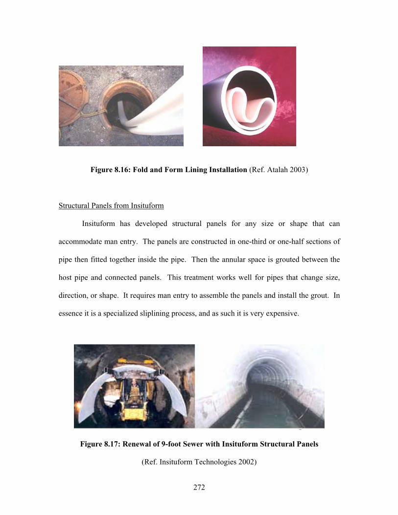
272
Figure 8.16: Fold and Form Lining Installation (Ref. Atalah 2003)
Structural Panels from Insituform
Insituform has developed structural panels for any size or shape that can
accommodate man entry. The panels are constructed in one-third or one-half sections of
pipe then fitted together inside the pipe. Then the annular space is grouted between the
host pipe and connected panels. This treatment works well for pipes that change size,
direction, or shape. It requires man entry to assemble the panels and install the grout. In
essence it is a specialized sliplining process, and as such it is very expensive.
Figure 8.17: Renewal of 9-foot Sewer with Insituform Structural Panels
(Ref. Insituform Technologies 2002)
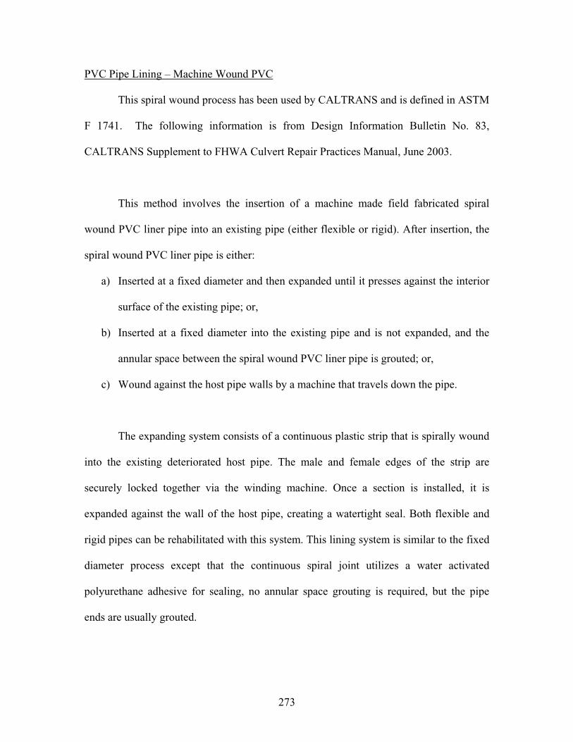
273
PVC Pipe Lining – Machine Wound PVC
This spiral wound process has been used by CALTRANS and is defined in ASTM
F 1741. The following information is from Design Information Bulletin No. 83,
CALTRANS Supplement to FHWA Culvert Repair Practices Manual, June 2003.
This method involves the insertion of a machine made field fabricated spiral
wound PVC liner pipe into an existing pipe (either flexible or rigid). After insertion, the
spiral wound PVC liner pipe is either:
a) Inserted at a fixed diameter and then expanded until it presses against the interior
surface of the existing pipe; or,
b) Inserted at a fixed diameter into the existing pipe and is not expanded, and the
annular space between the spiral wound PVC liner pipe is grouted; or,
c) Wound against the host pipe walls by a machine that travels down the pipe.
The expanding system consists of a continuous plastic strip that is spirally wound
into the existing deteriorated host pipe. The male and female edges of the strip are
securely locked together via the winding machine. Once a section is installed, it is
expanded against the wall of the host pipe, creating a watertight seal. Both flexible and
rigid pipes can be rehabilitated with this system. This lining system is similar to the fixed
diameter process except that the continuous spiral joint utilizes a water activated
polyurethane adhesive for sealing, no annular space grouting is required, but the pipe
ends are usually grouted.

274
Figure 8.18: Machine Wound PVC installation
(Ref. California DOT 2003)
The fixed diameter machine spiral wound liner process produces a renovated pipe,
which is a layered composite of PVC Liner (using ribbed PVC strips 200 to 300 mm wide
that are supplied in 100 meter coils), cementitous grout, and the original pipe. The
combination of the ribbed profile on the PVC liner and the grout produces an integrated
structure with the PVC liner "tied" to the original pipe through the grout similar to a
slipliner. Unlike the expanding system, after insertion, the annular space between the
liner and the existing pipe is filled with grout.

275
Figure 8.19: Rib Loc RibsteelTM Lining System Installation
(Ref. California DOT 2003)
The full bore, traveling machine system consists of a continuous plastic strip that
is spirally wound into the existing deteriorated host pipe, with the option of a steel
reinforcing section for increased load carrying capacity, by a machine that rotates and
lays the profile against the host pipe walls as the machine traverses the host pipe. The
male and female edges of the strip are securely locked together via the winding machine.
The plastic strip is designed with ribs on its outer surface to engage a continuous strip of
profiled reinforcing steel, which is added to the outside of the plastic pipe when specified.
For many smaller applications the steel reinforcing is not required as the plastic strip has
sufficient stiffness to withstand the grouting pressure. The resulting liner has a smooth
plastic internal surface with increased stiffness from the steel reinforcing profile (if
specified).
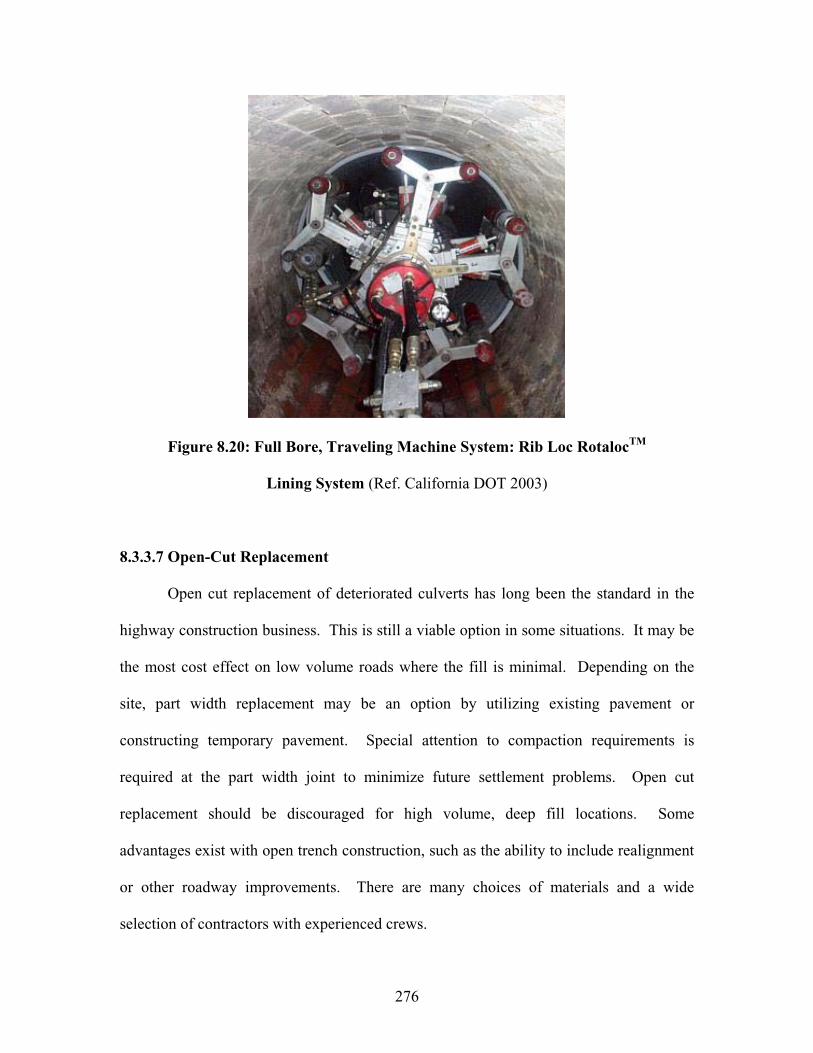
276
Figure 8.20: Full Bore, Traveling Machine System: Rib Loc RotalocTM
Lining System (Ref. California DOT 2003)
8.3.3.7 Open-Cut Replacement
Open cut replacement of deteriorated culverts has long been the standard in the
highway construction business. This is still a viable option in some situations. It may be
the most cost effect on low volume roads where the fill is minimal. Depending on the
site, part width replacement may be an option by utilizing existing pavement or
constructing temporary pavement. Special attention to compaction requirements is
required at the part width joint to minimize future settlement problems. Open cut
replacement should be discouraged for high volume, deep fill locations. Some
advantages exist with open trench construction, such as the ability to include realignment
or other roadway improvements. There are many choices of materials and a wide
selection of contractors with experienced crews.
277
CHAPTER 9: SUMMARY AND CONCLUSIONS
9.1 SUMMARY
After performing an extensive literature review related to culvert inspection and
risk assessment, a national survey was conducted to gain insights into state/district
DOTs’ culvert inspection policies and procedures. A set of eighteen survey questions
were finalized between ORITE and Ohio Department of Transportation (ODOT) and sent
electronically via the ODOT e-mail listing to DOTs. Two electronic mailings plus
telephone follow-up were used to maximize the return. The questionnaire responses were
analyzed carefully to point out national trends and innovative or creative solutions (if
any) developed by some highway agencies.
Periodic inspection of culverts is an essential element for identifying the need for
culvert maintenance, repair, or rehabilitation. Field inspection of a culvert structure can
be a major task, since it involves systematic evaluations of the culvert material
conditions, culvert shape and alignments, scouring at culvert ends, conditions of
headwalls/wingwalls, roadway settlement, and embankment slope conditions. To develop
an effective culvert field inspection program for the Ohio Department of Transportation,
a comprehensive research project focused on culvert inspection and risk assessment
methods was conducted by a team consisting of ORITE (Ohio University) and a sub-
contractor (Jobes Henderson and Associates, Inc.).
278
An inventory list was requested from each ODOT district office for culverts that
were recommended for the field inspection phase of this research. The selection criteria
were left up to each ODOT district office. Sixty culverts (25 concrete, 25 metal, 10
thermoplastic) were selected from the inventory lists based on the diversity of the culvert
type, geographical location, age, size, material type, shape, ADT, and water pH.
Before visiting each site, culvert background information were reviewed. This
included general inventory data, maintenance records, and past inspection records. Then,
field inspection work began by verifying the general inventory data (location, material,
shape, coating, height of cover). The conditions of the culvert, roadway surface,
headwall, channel, and embankment were noted, rated, and photographed. Both the
ODOT and proposed rating systems were used in the field inspection. Two inspection
data sheets were filed during/after the field inspection work. The field inspection phase
produced a minimum sufficient amount of data for performing multi-variable statistical
analysis and developing a risk assessment methodology.
Statistical analysis was performed using the collected data to identify key
parameters that have a significant influence on the general rating of highway culverts in
Ohio. The analysis was performed using the data collected according to both the ODOT
and proposed rating systems to verify the overall effectiveness of the ODOT culvert
rating methods. Statistical approaches used in the analysis included linear and nonlinear
multi-variable regression models and tests of significance. The ODOT equations were
applied to the collected data to estimate the culvert material durability. A methodology
279
was proposed for evaluating culvert risk assessment, which was developed based on
calculating the adjusted overall rating (AOR) of each culvert for both the ODOT and
proposed rating systems. Maintenance immediacy and inspection course of action
proposed by NCHRP 251 (1982) was correlated to each adjusted overall rating.
As developed by Jobes Henderson and Associates Inc., Chapter 8 described the
current state-of-the-art and state-of-practice for culvert rehabilitation, upgrade, and
replacement, using information gathered from a wide range of sources (professional
journals, conference proceedings, manufacturer handbooks, and reports issued by FHWA
and state DOTs, …). The topics covered in the chapter included invert
treatment/replacement, masonry repointing, timber bracing, joint sealing, barrel
reshaping, concrete lining, slip-lining, pipe jacking, pipe bursting, horizontal earth
boring, tunneling, and open-cut replacement. A table was included to present guidelines
for selecting proper culvert rehabilitation and replacement methods.
9.2 CONCLUSIONS
An extensive list of conclusions was reached during this study because of its
multi-phased nature. Therefore, the conclusions are presented below according to the
project objectives and tasks.
9.2.1 National Survey
One of the major tasks in this project was to conduct a national survey on
highway culvert management policies and inspection/rating procedures. Forty responses
280
were received, thirty-seven of which were from state DOTs. The following conclusions
were obtained from the national survey:
Forty-eight percent (48%) of the respondents were either bridge or hydraulic
department personnel. Seventy-five percent (75%) of the respondents had prior
experience in inspecting highway culvert structures. A variety of personnel are
performing culvert inspection; including highway workers, engineers, and
consultants.
Forty-four percent (44%) of all respondents and forty-six percent (46%) of the
responding state/district DOTs addressed confined space issues with regard to
culverts.
Sixty percent (60%) of the responding state/district DOTs have developed culvert
inspection polices, and fifty-five percent (55%) of these specify the frequency of
culvert inspection. Forty-eight percent (48%) of the respondents specified a one
to two year cycle for culvert inspection, while sixteen percent (16%) specified a
three to five year cycle. It should be noted that 60-70% of the respondent state
DOTs borrowed the AASHTO definition (span 20 ft or 6.1 m) for the culvert.
More than half of the responding state DOTs have applied numerical rating
systems to evaluate in-service conditions of highway culverts. Among them, only
five (equivalent to 13%) state/district DOTs other than Ohio have developed their
own culvert inspection manual. Twenty-eight percent (28%) of the responding
state DOTs apply the culvert numerical rating system developed by FHWA. Only
one state other than Ohio (Texas) has developed a numerical rating system to

281
visually evaluate thermoplastic pipe culverts. Only five state DOTs have
developed their own culvert risk assessment procedure.
Fifty-seven percent (57%) of the responding state/district DOTs have a computer
database to manage culverts.
Most state/district DOTs based their decision to remove existing culverts on
structural material deterioration, road surface conditions, and culvert shape
(deflections). Culvert age and numerical rating scores are less cited in culvert
replacement decision process.
9.2.2 New Culvert Management Policies/Procedures
Ohio Department of Transportation (ODOT) recently established new highway
culvert management policies, inspection procedures, and rating methods. According to
the new guidelines, any culvert having a span or diameter between 1 and 10 ft (0.3 and
3.1 m) should be inspected at least once every 5 years. ODOT developed two forms (CR-
86, CR-87) to standardize the culvert data collection and data management in Ohio. The
first form (CR-86) is an inventory data sheet, consisting of basic information such as
culvert location, type, size, past modifications as well as hydrology/hydraulics data. The
second form (CR-87) is a one-page culvert inspection document that requires 1 to 9 rating
scores to be entered for reporting the conditions of the culvert, channel, and approaches.
9.2.3 Culvert Field Inspections
In the field inspection phase of this project, a total of sixty (25 metal, 25 concrete,
and 10 thermoplastic pipe) highway culverts were inspected in a comprehensive manner

282
using the ODOT as well as the proposed culvert rating systems. These sixty structures
selected in the project represented a wide variation in terms of their geographical
locations, environmental conditions, age, ADT, and height of soil cover. The following
summarizes some of the conclusions regarding filed inspections:
Environmental data collected at these sites were largely consistent with the state
pH and flow abrasiveness maps produced by the ODOT Culvert Durability Study
(ODOT, 1982).
Conditions of the culvert structure, concrete headwalls, embankment slopes, and
roadway surface rated and documented at the sites provided an overall picture of
how each major type of culverts performs over time under major highways in
Ohio.
None of the concrete culverts had exhibited serious alignment problems. Also, the
roadway surface over the concrete culverts showed no settlement problems.
Based on this study, the service life of concrete culverts in Ohio appeared to be
limited to 70 to 80 years.
A total of nineteen (19) different characteristic conditions existed among the 25
concrete culvert sites. The most frequently encountered conditions were
deteriorated headwalls, deterioration of concrete in the crown region/top slab and
inlet end, and transverse shear cracks on abutment walls. In contrast, the least
common conditions included cavity formation in adjacent soil fill, longitudinal
crack(s), and embankment slope stability problem.
283
Overall ODOT rating scores were very similar between the cast-in-place concrete
box culverts and reinforced concrete circular/elliptical pipe (RCP) culverts.
No serious culvert alignment problems were found at most metal culvert sites. No
stress cracks were detected at the bolt lines inside any of the metal culverts.
Based on the results of this study, the service life of metal culverts in Ohio
appears to be limited to 60 to 65 years.
A total of twenty-eight (28) different characteristic conditions existed among the
twenty-five metal culvert sites. The most frequently encountered conditions were
perforated invert, perforations at flow line, scour hole at inlet or outlet end, and
movement on the concrete headwalls. The main location of perforation was in the
invert for District 10 culverts and at the normal flow line for culverts outside
District 10. In contrast, the least common conditions included severe rusting of
plate edges and bolts at seams, pinholes in the top arc, reversal of curvature, and
piping holes above the culvert.
For metal culverts, the average ODOT rating score was the lowest on the general
material condition. The second lowest average ODOT rating score was associated
with the culvert shape. According to the proposed rating system applications,
material deterioration was more of a concern for the invert region than for the
other regions.
The proposed rating scores established for the inlet and outlet end sections
showed that at most metal culvert sites the inlet end section was no worse than the
outlet end section.
284
A total of twelve (12) different characteristic conditions were detected at ten
thermoplastic pipe culvert sites. The most frequently encountered conditions
were deflections larger than 7.5%, localized buckling of internal liner, and minor
misalignment at joints. In contrast, the least common conditions recorded at the
sites were separation of hydraulic liner, scour holes at inlet or outlet, and
embankment slope instability.
Due to a lack of field inspection data, no statement can be made concerning the
service life of thermoplastic pipe culverts in Ohio.
Inspection data indicated that the flexible (metal, thermoplastic pipe) culverts
were sensitive to the installation conditions. Special attention is required during
flexible culvert construction to make sure that it is installed according to
specifications.
The case of NOB-145-3.59 showed that a thermoplastic pipe can perform
satisfactory for at least 20 years under severe (low pH, abrasive flow, shallow
cover) service conditions.
Results from application of the proposed rating system showed that the springline
is the region where the first sign of structural distresses usually develops inside
thermoplastic pipe culverts.
9.2.4 Statistical Analysis, Assessment of ODOT Durability Equations, and Risk
Assessment Method
This section presents conclusions and discussions of the statistical analysis,
assessment of ODOT durability equations, and risk assessment of the inspected culverts.
285
9.2.4.1 Statistical Analysis of Data Collected for Metal Culverts
The effects of the various independent variables listed in Table 7.1 were analyzed
with respect to their effect on metal ratings (GA = general rating for ODOT rating
systems and OMR = overall metal rating for the proposed rating systems).
Age, rise, and culvert type were determined to be significant variables based
on both rating systems.
Water pH, abrasiveness, and flow velocity were also significant variables based
on the proposed rating system.
The linear regression model based on the ODOT rating system yielded the
original and adjusted R2 value of 0.5 and 0.43, respectively. The linear regression
model based on the proposed rating system had the original and adjusted R2 value
of 0.81 and 0.75, respectively.
The analysis overall showed that the proposed rating system detected more
significant variables and had a higher value of R2. This supports the fact that the
proposed rating system had a higher resolution.
9.2.4.2 Statistical Analysis of Data Collected for Concrete Culverts
Field data collected at concrete culvert sites were analyzed to determine the
significant variables that affect the durability of concrete culverts exposed to various in-
service conditions. Several independent variables (listed in Table 7.6) were analyzed
with respect to their effect on concrete ratings (GA = general rating for ODOT and OCSR
= overall concrete surface rating for the proposed rating systems).

286
Age and pH were significant variables based on both rating systems.
Abrasiveness (of drainage flow) was also a significant variable based on the
ODOT rating system.
Analysis showed that the linear regression model based on the ODOT rating
system detected more significant variables and had a higher R2 value, even though
the proposed rating system had higher resolutions and had more details for culvert
inspection. Based on the low R2 values resulted from both methods, additional
data collection would be warranted.
The statistical analysis was based on a small sample size (25 concrete culverts).
Analysis of a larger sample size would reveal more details and increase the level
of accuracy.
9.2.4.3 Statistical Analysis of Data Collected for Thermoplastic Pipe Culverts
Very limited statistical analysis could be performed on the thermoplastic pipe
culverts, since only ten pipes were inspected and the average age was only about five
years.
9.2.4.4 Assessment of ODOT Durability Equations
In the current study, the metal culvert durability equations, developed during the
ODOT Culvert Durability Study (ODOT, 1982), were re-evaluated using the inspection
data collected at twenty-five metal culvert sites in Ohio. Prior to the analysis, each
original metal rating score obtained in the 0-to-9 scale had to be converted to an
equivalent score in the 1-to-4 scale.

287
The ODOT durability equations predicted the metal ratings relatively closely to
the values assessed in the field under both the ODOT and proposed rating
systems. In one isolated case (Metal Culvert No. 17), the ODOT metal culvert
durability equations yielded a metal rating that was out of line with the actual
metal conditions observed at the site. This was mainly due to uncertainty
associated with its overall age, for the sections of this culvert structure was
repaired subsequent to the original construction.
Overall, results of the re-evaluation effort indicated that the current ODOT
durability evaluation procedure for metal culverts appears to be reasonably
accurate.
9.2.4.5 Risk Assessment of Inspected Culverts
Chapter 7 proposed a simple yet comprehensive methodology for evaluating risk
assessment for each major culvert type. This methodology was developed based on the
field inspection data and statistical analysis results obtained under both the ODOT and
proposed culvert rating systems. The method adjusts the original overall culvert rating
score by applying rating modifiers due to the culvert age, pH of drainage water,
abrasiveness of drainage flow, and the height of soil cover to culvert rise ratio. And, the
maintenance immediacy action plan developed by NCHRP Report No. 251 (1982) was
adopted to relate the adjusted overall culvert rating (AOR) score to the recommended
course of action.

288
The AOR scores for the metal culverts based on the ODOT rating system were
between 2 and 6. Metal Culverts No.3 and 16 had the highest and high priority of
maintenance immediacy actions, respectively. The rest of the metal culverts’
AOR scores were between 4 and 6. Therefore, their maintenance immediacy
actions were mostly between 4 (Priority - current season) and 6 (Add to
Scheduled work by end of next season).
Very similar results were obtained for the AOR scores for the metal culverts
under the proposed rating system. This supports the previous conclusion that the
ODOT rating system for metal culverts is basically sound but can be improved
further by adapting the additional elements (such as separate rating of the culvert
ends, rating of the protective coating, rating of the invert paving, rating of the
footing, …) contained in the proposed rating system.
The AOR scores for the concrete culverts under the ODOT rating system were
between 2 and 6. Concrete Culvert No.12 had the highest priority maintenance
immediacy actions. Concrete Culvert Nos. 11 and 15 both required high priority
of maintenance immediacy actions. For the rest of the concrete culverts, the AOR
scores were between 4 and 6. Thus, their maintenance immediacy actions were
between 4 (priority - current season) and 6 (Add to scheduled work by end of next
season).
Very similar results were obtained for the AOR scores for the concrete culverts
under the proposed rating system. This supports the previous conclusion that the
ODOT rating system for concrete culverts is basically sound but can be improved
289
further by adapting additional elements (such as separate rating of the culvert
ends, rating of the footing, …) contained in the proposed rating system.
The AOR scores for the thermoplastic pipe culverts under the ODOT rating
system were between 6 and 9. Their maintenance immediacy actions were
therefore between 6 (add to scheduled work by end of next season) and 9 (no
repairs needed).
The AOR scores of the thermoplastic pipe culverts based on the proposed rating
system was between 5 and 9. Thus, their maintenance immediacy actions were
between 5 (Place in current schedule - current season- first reasonable
opportunity) and 9 (no repairs needed).
It was observed for some combinations of the culvert type and the rating system
that the AOR score was equal to the lowest of the individual item rating scores for
almost half of the field cases examined. This observation should not lead to
abandonment of the proposed risk assessment method. The factors involved in
the AOR calculation (such as age, water pH, flow abrasiveness, and cover height
to rise ratio) are all very important and must be considered in prioritizing the
culverts in the culvert management plan.
9.2.5 Culvert Rehabilitation Techniques
The key to determining the best rehabilitation techniques is to arm the program
manager and designer with a toolbox options. This requires that the existing structure be
analyzed for deficiencies and that the cause of the current problems be determined. The
cause must be addressed in selecting the appropriate treatment.

290
Overall the best option will be the one that is appropriate structurally,
hydraulically, environmentally, and fiscally. Several options have been presented
in Chapter 8, with the following providing the most promise for use on a regular
basis:
Slip-Lining ------------------------------------------ Section 8.3.2.2, Appendix G
Cured-In-Place Pipe (CIPP) ---------------------- Section 8.3.2.3, Appendix G
Invert Replacement Using Concrete or Gunite
---------------- Sections 8.3.1.1 & 8.3.1.6, Appendix G
Filling Voids ---------------------------------------- Section 8.3.1.4
Repair Sleeves for Localized Problems --------- Section 8.3.1.4
If slip-lining options decrease the hydraulic capacity too much or if the host
culvert changes direction and does not allow the installation of a liner pipe, then
CIPP should be considered as an alternative. CIPP is a good choice if water is
readily available with heating options and disposal of heated water. The water
will most likely need to be disposed of into a water treatment facility. Steam may
be used as an alternative, but the heated steam also needs to be cooled and
released with care. If CIPP is used to repair structural deficiencies, the pipe
material must be designed to provide structural support.
Invert problems are common in Ohio, particularly in low pH areas. Invert
replacement has been used successfully and is very cost effective if the
installation is done in a quality manner.
291
Filling voids can be a stand-alone treatment or included with sliplining, CIPP, and
invert paving operations. It is important to fill voids before other treatments are
undertaken to assure interaction between new barrels and the host pipe.
Repair sleeves come in a variety of sizes, shapes and materials. Using repair
sleeves is a form of preventative maintenance and can save money by repairing
minor joint problems before more costly treatments are necessary. Manufacturers
could train ODOT in-house staff on installation procedures as part of their
Highway Technician Training Program.
Table 9.1 summarizes the treatments discussed in Chapter 8. Rough cost
information is also included to compare alternatives. There are other treatments
available, but the ones illustrated here are the most promising for highway culvert
barrel maintenance, rehabilitation, and replacement.
Many states recognize the need for a culvert inspection and renovation program, but
few have made a full commitment to addressing the issue. California, Ohio and
Indiana are leading the way. They have tried a variety of techniques and are looking
toward the future for more innovative options. Indiana has allocated funds
specifically to culvert replacement and repair. Without a financial commitment the
needs may go unaddressed. Everyone involved in the program process needs to
recognize the safety implications and value of using innovative repair and
replacement techniques wisely.
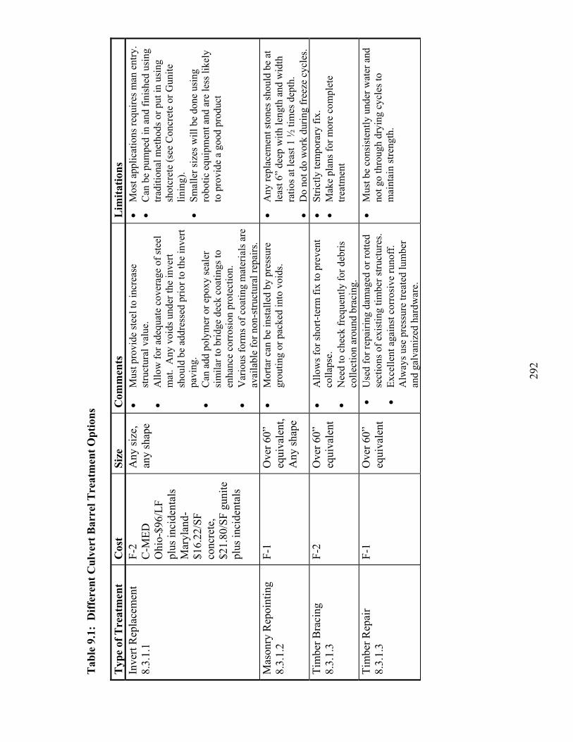
292
Tab
le 9
.1:
Dif
fere
nt C
ulve
rt B
arre
l Tre
atm
ent
Opt
ions
Typ
e of
Tre
atm
ent
Cos
t Si
ze
Com
men
ts
Lim
itat
ions
In
vert
Rep
lace
men
t 8.
3.1.
1F-
2C
-MED
Ohi
o-$9
6/LF
pl
us in
cide
ntal
s M
aryl
and-
$16.
22/S
Fco
ncre
te,
$21.
80/S
F gu
nite
pl
us in
cide
ntal
s
Any
size
, an
y sh
ape
Mus
t pro
vide
stee
l to
incr
ease
st
ruct
ural
val
ue.
Allo
w fo
r ade
quat
e co
vera
ge o
f ste
el
mat
. A
ny v
oids
und
er th
e in
vert
shou
ld b
e ad
dres
sed
prio
r to
the
inve
rt pa
ving
.C
an a
dd p
olym
er o
r epo
xy se
aler
si
mila
r to
brid
ge d
eck
coat
ings
to
enha
nce
corr
osio
n pr
otec
tion.
V
ario
us fo
rms o
f coa
ting
mat
eria
ls a
re
avai
labl
e fo
r non
-stru
ctur
al re
pairs
.
Mos
t app
licat
ions
requ
ires m
an e
ntry
. C
an b
e pu
mpe
d in
and
fini
shed
usi
ng
tradi
tiona
l met
hods
or p
ut in
usi
ng
shot
cret
e (s
ee C
oncr
ete
or G
unite
lin
ing)
.Sm
alle
r siz
es w
ill b
e do
ne u
sing
ro
botic
equ
ipm
ent a
nd a
re le
ss li
kely
to
pro
vide
a g
ood
prod
uct
Mas
onry
Rep
oint
ing
8.3.
1.2
F-1
Ove
r 60”
eq
uiva
lent
,A
ny sh
ape
Mor
tar c
an b
e in
stal
led
by p
ress
ure
grou
ting
or p
acke
d in
to v
oids
. A
ny re
plac
emen
t sto
nes s
houl
d be
at
leas
t 6”
deep
with
leng
th a
nd w
idth
ra
tios a
t lea
st 1
½ ti
mes
dep
th.
D
o no
t do
wor
k du
ring
free
ze c
ycle
s.
Tim
ber B
raci
ng
8.3.
1.3
F-2
Ove
r 60”
eq
uiva
lent
Allo
ws f
or sh
ort-t
erm
fix
to p
reve
nt
colla
pse.
Nee
d to
che
ck fr
eque
ntly
for d
ebris
co
llect
ion
arou
nd b
raci
ng.
Stric
tly te
mpo
rary
fix.
M
ake
plan
s for
mor
e co
mpl
ete
treat
men
t
Tim
ber R
epai
r 8.
3.1.
3F-
1 O
ver 6
0”
equi
vale
ntU
sed
for r
epai
ring
dam
aged
or r
otte
d se
ctio
ns o
f exi
stin
g tim
ber s
truct
ures
. Ex
celle
nt a
gain
st c
orro
sive
runo
ff.
Alw
ays u
se p
ress
ure
treat
ed lu
mbe
r an
d ga
lvan
ized
har
dwar
e.
Mus
t be
cons
iste
ntly
und
er w
ater
and
no
t go
thro
ugh
dryi
ng c
ycle
s to
mai
ntai
n st
reng
th.

293
Typ
e of
Tre
atm
ent
Cos
t Si
ze
Com
men
ts
Lim
itat
ions
Se
alin
g Jo
ints
and
V
oids
8.3.
1.4
F-1
C-L
owM
an e
ntry
, ge
nera
llyat
leas
t 36
”
Cra
cks o
r joi
nts t
hat a
re m
ovin
g sh
ould
be
fille
d w
ith a
flex
ible
mat
eria
l.
Cra
cks a
nd jo
ints
that
are
stab
le sh
ould
be
fille
d w
ith a
rigi
d m
ater
ial.
C
an u
se d
iffer
ent t
ypes
of b
ands
for
isol
ated
pro
blem
are
as. S
ee S
ectio
n 8.
3.1.
4 fo
r det
ails
. Fill
voi
ds b
efor
e ad
ding
ban
ds.
Mus
t be
sure
that
air
or w
ater
is n
ot
trapp
ed w
hen
fillin
g vo
ids a
nd c
rack
s.
Ver
y im
porta
nt to
det
erm
ine
the
exte
nt o
f the
voi
ds.
M
ost c
omm
on p
ract
ice
for i
nsta
lling
gr
out m
ater
ials
is to
pla
ce tu
bes a
t top
an
d bo
ttom
of v
oid
and
pres
sure
gro
ut
into
bot
tom
unt
il th
e gr
out c
omes
out
th
e to
p.V
oids
und
er c
ulve
rts m
ay b
e fil
led
by
grav
ity b
ut it
is b
est t
o de
wat
er th
e ar
ea fi
rst o
r the
pro
perti
es o
f the
gro
ut
will
cha
nge
as th
e ad
ditio
nal w
ater
is
enco
unte
red
lead
ing
to a
poo
r gro
ut
mix
.C
oncr
ete
Lini
ng
(Sho
tcre
te o
r Gun
ite)
8.3.
1.6
F-2
C-H
igh
Ove
r 60”
G
ood
for o
dd sh
aped
pip
es, b
est f
or
fixin
g cr
acks
and
min
or jo
int d
efec
ts
befo
re v
oids
hav
e fo
rmed
. Als
o go
od
for h
eadw
alls
, win
gwal
ls, a
nd p
avin
g in
verts
.C
an b
e a
stru
ctur
al re
pair
if re
info
rcin
g is
incl
uded
. Var
iety
of m
ixes
ava
ilabl
e w
ith a
dditi
ves.
Pro
vide
s cor
rosi
on
resi
stan
ce fo
r met
al p
ipes
. G
ood
choi
ce fo
r cha
nges
in d
irect
ion
or
odd
shap
es.
Elim
inat
es th
e ne
ed fo
r for
m w
ork.
B
onds
wel
l to
conc
rete
, mas
onry
, roc
k,
stee
l.C
an p
ut in
var
iabl
e th
ickn
ess a
s nee
ded.
M
ay in
crea
se fl
ow c
apac
ity b
y re
duci
ng
roug
hnes
s on
corr
ugat
ed p
ipes
.
Req
uire
s man
ent
ry.
Look
s lik
e pr
ecas
t whe
n do
ne, n
eed
expe
rienc
ed ‘n
ozzl
eman
’ for
gun
ite
sinc
e he
is c
ontro
lling
the
wat
er b
eing
ad
ded.
May
nee
d si
gnifi
cant
foot
prin
t for
se
tting
up
conc
rete
pum
ping
or
mix
ing
oper
atio
n.
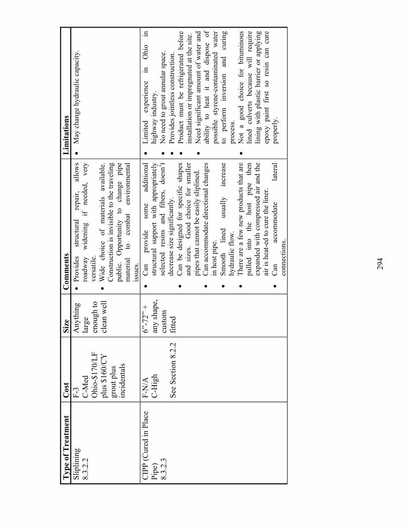
294
Typ
e of
Tre
atm
ent
Cos
t Si
ze
Com
men
ts
Lim
itat
ions
Sl
iplin
ing
8.3.
2.2
F-3
C-M
edO
hio-
$170
/LF
plus
$16
0/C
Y
grou
t plu
s in
cide
ntal
s
Any
thin
gla
rge
enou
gh to
cl
ean
wel
l
Prov
ides
st
ruct
ural
re
pair,
al
low
s ro
adw
ay
wid
enin
g if
need
ed,
very
ve
rsat
ile.
Wid
e ch
oice
of
m
ater
ials
av
aila
ble.
C
onst
ruct
ion
is in
visi
ble
to th
e tra
velin
g pu
blic
. O
ppor
tuni
ty
to
chan
ge
pipe
m
ater
ial
to
com
bat
envi
ronm
enta
l is
sues
.
May
cha
nge
hydr
aulic
cap
acity
.
CIP
P (C
ured
in P
lace
Pi
pe)
8.3.
2.3
F-N
/AC
-Hig
h
See
Sect
ion
8.2.
2
6”-7
2” +
any
shap
e,
cust
om
fitte
d
Can
pr
ovid
e so
me
addi
tiona
l st
ruct
ural
sup
port
with
app
ropr
iate
ly
sele
cted
re
sins
an
d fib
ers,
does
n’t
decr
ease
size
sign
ifica
ntly
.
Can
be
desi
gned
for
spe
cific
sha
pes
and
size
s. G
ood
choi
ce f
or s
mal
ler
pipe
s tha
t can
not b
e ea
sily
slip
lined
.
Can
acc
omm
odat
e di
rect
iona
l cha
nges
in
hos
t pip
e.
Smoo
th
lined
us
ually
in
crea
se
hydr
aulic
flow
.
Ther
e ar
e a
few
new
pro
duct
s th
at a
re
pulle
d in
to
the
host
pi
pe
then
ex
pand
ed w
ith c
ompr
esse
d ai
r and
the
air i
s hea
t-ed
to c
ure
the
liner
. C
an
acco
mm
odat
e la
tera
l co
nnec
tions
.
Lim
ited
expe
rienc
e in
O
hio
in
high
way
indu
stry
.
No
need
to g
rout
ann
ular
spac
e.Pr
ovid
es jo
intle
ss c
onst
ruct
ion.
Pr
oduc
t m
ust
be r
efrig
erat
ed b
efor
e in
stal
latio
n or
impr
egna
ted
at th
e si
te.
Nee
d si
gnifi
cant
am
ount
of w
ater
and
ab
ility
to
he
at
it an
d di
spos
e of
po
ssib
le s
tyre
ne-c
onta
min
ated
wat
er
to
perf
orm
in
vers
ion
and
curin
g pr
oces
s.N
ot a
goo
d ch
oice
for
bitu
min
ous
lined
cu
lver
ts
beca
use
will
re
quire
lin
ing
with
pla
stic
bar
rier
or a
pply
ing
epox
y pa
int
first
so
resi
n ca
n cu
re
prop
erly
.
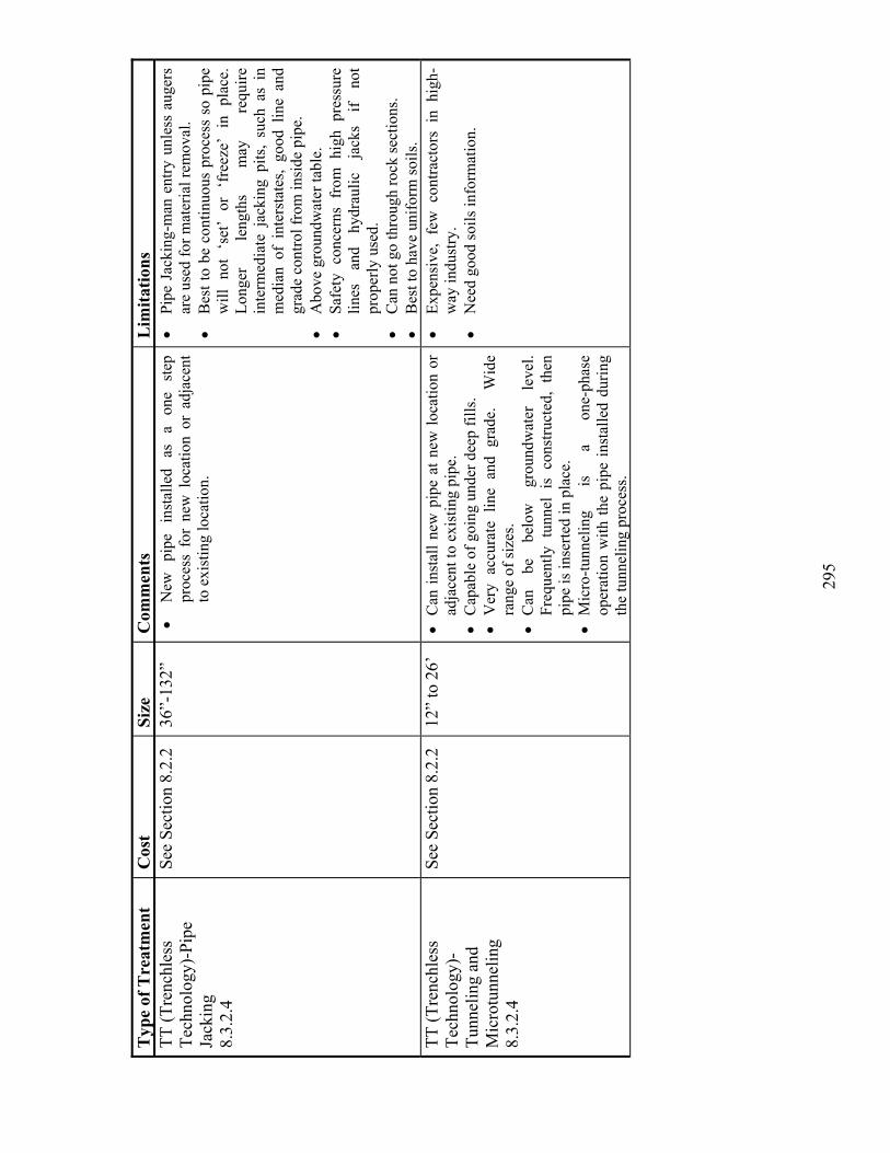
295
Typ
e of
Tre
atm
ent
Cos
t Si
ze
Com
men
ts
Lim
itat
ions
TT
(Tre
nchl
ess
Tech
nolo
gy)-
Pipe
Jack
ing
8.3.
2.4
See
Sect
ion
8.2.
2 36
”-13
2”
New
pi
pe
inst
alle
d as
a
one
step
pr
oces
s fo
r ne
w l
ocat
ion
or a
djac
ent
to e
xist
ing
loca
tion.
Pipe
Jac
king
-man
ent
ry u
nles
s au
gers
ar
e us
ed fo
r mat
eria
l rem
oval
. B
est t
o be
con
tinuo
us p
roce
ss s
o pi
pe
will
not
‘se
t’ or
‘fr
eeze
’ in
pla
ce.
Long
er
leng
ths
may
re
quire
in
term
edia
te j
acki
ng p
its,
such
as
in
med
ian
of i
nter
stat
es,
good
lin
e an
d gr
ade
cont
rol f
rom
insi
de p
ipe.
A
bove
gro
undw
ater
tabl
e.
Safe
ty c
once
rns
from
hig
h pr
essu
re
lines
an
d hy
drau
lic
jack
s if
not
prop
erly
use
d.
Can
not
go
thro
ugh
rock
sect
ions
. B
est t
o ha
ve u
nifo
rm so
ils.
TT (T
renc
hles
s Te
chno
logy
)-Tu
nnel
ing
and
Mic
rotu
nnel
ing
8.3.
2.4
See
Sect
ion
8.2.
2 12
” to
26’
C
an in
stal
l new
pip
e at
new
loca
tion
or
adja
cent
to e
xist
ing
pipe
.
Cap
able
of g
oing
und
er d
eep
fills
.
Ver
y ac
cura
te l
ine
and
grad
e.
Wid
e ra
nge
of si
zes.
Can
be
be
low
gr
ound
wat
er
leve
l. Fr
eque
ntly
tun
nel
is c
onst
ruct
ed,
then
pi
pe is
inse
rted
in p
lace
.M
icro
-tunn
elin
g is
a
one-
phas
e op
erat
ion
with
the
pipe
inst
alle
d du
ring
the
tunn
elin
g pr
oces
s.
Expe
nsiv
e, f
ew c
ontra
ctor
s in
hig
h-w
ay in
dust
ry.
Nee
d go
od so
ils in
form
atio
n.

296
Typ
e of
Tre
atm
ent
Cos
t Si
ze
Com
men
ts
Lim
itat
ions
Pi
pe B
urst
ing
8.3.
2.5
See
Sect
ion
8.2.
2 M
ax is
36
”R
epla
ces
a pi
pe a
t sam
e lo
catio
n w
ith a
la
rger
dia
met
er p
ipe.
Pr
ovid
es a
new
pi
pe st
ruct
ure.
Can
exp
and
pipe
up
to 3
0%.
Can
add
st
ruct
ural
inte
grity
.
No
need
for
byp
ass
pum
ping
; ca
n be
do
ne
unde
r no
rmal
or
lo
w
flow
co
nditi
ons.
Hos
t pi
pe
mus
t be
un
rein
forc
ed
conc
rete
, cl
ay
or
poss
ibly
w
eak
plas
tic.
Can
not
use
in e
xpan
sive
soils
. C
an n
ot fi
x lin
e an
d gr
ade
prob
lem
s.
Fold
and
For
m P
ipe
8.3.
2.6
C-M
ed to
Hig
h U
p to
24”
, ci
rcul
ar
Sim
ilar u
ses a
s CIP
P.
Smal
ler
size
s, PV
C (
AST
M F
150
4),
HD
PE.
No
grou
ting
need
ed.
Ea
sy tr
ansp
ort.
PVC
or
HD
PE p
ipe
that
is
fold
ed o
r de
form
ed s
o it
can
be p
ulle
d in
to h
ost
pipe
then
refo
rmed
. Sp
ecia
lized
equ
ipm
ent.
C
anno
t ha
ndle
jo
int
settl
emen
t or
di
amet
er v
aria
tions
. PV
C P
ipe
Lini
ng -
Mac
hine
Wou
nd P
VC
8.
3.2.
6
C-H
igh
6”-9
’ R
elin
es a
pip
e w
ith P
VC
.A
STM
F- 1
741.
Var
ious
ty
pes
of
tech
niqu
es,
som
e re
quire
gro
utin
g.
Smal
l foo
tprin
t for
wor
k ar
ea.
Lim
ited
supp
liers
. N
ot in
com
mon
usa
ge.
No
perf
orm
ance
dat
a.Si
mila
r lim
itatio
ns a
s PV
C sl
iplin
ing.
Sp
ecia
lized
eq
uipm
ent.
Har
d to
ha
ndle
dia
met
er c
hang
es.
Ope
n C
ut
Rep
lace
men
t 8.
3.2.
7
See
Sect
ion
8.2.
2 A
ny si
ze,
Any
shap
e To
tal
repl
acem
ent
of
pipe
; ca
n ad
d st
ruct
ural
stre
ngth
and
cap
acity
. A
ny c
hoic
e of
mat
eria
l. C
onve
ntio
nal
styl
e co
nstru
ctio
n w
ell t
este
d.
Can
incl
ude
road
way
alig
nmen
t cha
nges
in
pro
ject
.
Can
be
expe
nsiv
e, e
spec
ially
for d
eep
fill.
Hig
h us
er
cost
s ca
used
by
la
ne
clos
ures
and
det
ours
.
Cos
t C
odes
The
abov
e co
lum
n la
bele
d co
sts c
an b
e in
terp
rete
d us
ing
the
follo
win
g ke
y:
F=
cost
rela
tive
to re
plac
emen
t as i
ndic
ated
in F
HW
A-R
D-9
5-08
9, C
ulve
rt R
epai
r Pra
ctic
es M
anua
l, V
olum
e II
, May
199
5. S
cale
of 1
(Low
) – 5
(H
igh)
;C =
cos
t as i
ndic
ated
in D
esig
n In
form
atio
n B
ulle
tin N
o. 8
3, C
ALT
RA
NS
Supp
lem
ent t
o FH
WA
Cul
vert
Rep
air P
ract
ices
Man
ual,
June
20
03. S
cale
of L
ow to
Hig
h; a
nd O
hio
= O
hio’
s cos
ts b
ased
on
bid
tabs
and
Sum
mar
y of
Con
tract
s Aw
arde
d.
297
9.2.6 Demonstration of CPT Sounding Technique
Results of the cone penetration test (CPT) investigations conducted at selected
culvert sites are presented in Appendix H. During the current study, it was demonstrated
at a few sites that the cone penetration test (CPT) can be a useful tool for evaluating the
quality of backfill soil envelope around the culvert. The zone of weak (or loose) soil or
voids near the culvert can be easily identified, without open excavation, through
significant reductions in the tip resistance and sleeve friction readings. In most cases, the
CPT sounding can be achieved relatively quickly by closing only one traffic lane. The
only difficulty associated with the application of CPT is that prior to each testing the hole
location must be precisely determined on the roadway surface, so that the CPT probe will
penetrate within a few feet of the culvert.

298

299
CHAPTER 10: IMPLEMENTATIONS
Based on the findings made and conclusions reached in the current
comprehensive study on highway culverts, the following general implementation plans
are recommended by the authors:
The drainage water pH contour map published by the ODOT Culvert Durability
study (ODOT, 1982) can still be used for evaluating the normal pH of the
drainage flow in Ohio.
In 96% of the metal culverts inspected, the ODOT culvert durability formulas
developed 20 years ago proved to be still reliable in estimating the metal culvert
material durability. Therefore, the metal culvert durability equations, developed
during the ODOT culvert durability study (ODOT, 1982) can be continually
utilized to predict the service life of metal culverts. Prior to the use of the
durability procedure, the metal rating score must be converted from the 0-to-9
scale value to an equivalent value based on the previous 1-to-4 scale. It is
recommended that the formulas be verified further since the outcome for one
metal culvert was not consistent.
To better convey information to County and District personnel, the portions of
this report (especially Chapter 8 and Appendix G) should be used as a basis for A
Culvert Maintenance Manual or Supplement to the Maintenance Administration
Manual.

300
It is recommended that a specific Strategic Highway Research Program (SHRP)
be developed on the national level to apply several culvert rehabilitation options
in different environmental site conditions and track their progress during and after
construction phases.
It is recommended that the following changes/additions be made to the new
guidelines, policies, and methods presented in the ODOT Culvert Management
Manual (2003):
The metal culvert rating system developed by ODOT (2003) is basically sound.
However, it will become more effective if each culvert end is rated independently
from the main barrel, if the culvert material condition is evaluated in each region
(top, sides, invert) separately, if the rating system for protective coating is added,
if the rating system for invert pavement is added from the ODOT Culvert
Inspection Manual (1990), if vertical deflection is used exclusively to evaluate the
culvert shape, and if a clear instruction is given to rate the headwalls at inlet and
outlet separately.
The concrete culvert rating system developed by ODOT (2003) is basically sound.
However, its effectives can be improved further if each culvert end is rated
independently from the main barrel, if the culvert material condition is evaluated
in each region (top, sides, invert) separately, and if a clear instruction is given to
rate the headwalls at inlet and outlet separately.

301
The thermoplastic pipe culvert rating system developed by ODOT (2003) is
basically sound. However, it will become more complete if each culvert end is
rated independently from the main barrel, if the culvert material condition is
evaluated in each region (top, sides, invert) separately, if the degree of wall
cracking is addressed, if the vertical deflection is used exclusively to evaluate the
culvert shape, and if a clear instruction is given to rate the headwalls at inlet and
outlet separately.
Finally, the following additional recommendations are made to ODOT to achieve
an effective state-wide culvert management program and reduce the risk of structural
collapse of short-span culverts serving major highways in Ohio:
The culvert age, the cover height-to-rise ratio, and environmental conditions
(abrasive nature and pH of the drainage flow) prevailing at the site should be
factored into determining the frequency of field culvert inspection. Deteriorating
culverts that are older and/or having a low cover height-to-rise ratio should be
inspected more frequently.
Once a set of culverts is identified as needing work in any ODOT districts, the
AOR (adjusted overall rating) method presented in this report should be utilized
to prioritize the work schedule among the list. The lower the AOR score is, the
higher the priority for repairs/replacement. Then, based on the AOR score the
realistic time line for remedial work should be developed.
302
By the time this report was drafted, a few ODOT districts had each acquired a
personnel who would be conducting filed inspection of highway culverts
according to the new ODOT culvert rating systems. It is recommended that the
proposed culvert risk assessment method be applied by these personnel during the
data management phase. Also, as additional field inspection data are obtained, it
is recommended that these data be incorporated into the statistical analysis.
Installation of any culverts larger than 36 inches in diameter/rise at state highway
project sites should be monitored and documented more closely monitored and by
both contractors and state DOT personnel.
During the initial backfilling of flexible (metal, thermoplastic pipe) culvert, the
soil stiffness gauge (SSG) should be used, in stead of the conventional nuclear
moisture/density gauge. This is because stiffness is a better indicator of the
quality of soil fill than dry density. Guidelines for using the SSG in the flexible
pipe installation work can be found in a technical paper by Sargand et al. (2004).
The cone penetration test (CPT) should become an integral part of the overall
investigation efforts at any culvert site where the culvert performance has been
less than satisfactory and the cause of the poor performance is unknown.
303
BIBLIOGRAPHY
List for Chapters 1 Through 7 & Appendix H
AASHTO (1999). Volume XIV: Highway Drainage Guidelines for Culvert Inspection and Rehabilitation, Washington, D. C., 39 pp.
Abdel-Sayed, G., Bakht, B., and Jaeger, L. G. (1994). Soil-Steel Bridges – Design & Construction, First Edition, McGraw-Hill, Inc., New York, 357 pp.
Arnoult, J. D. (1986). Culvert Inspection Manual, FHWA-IP-86-2, Final Report, Federal Highway Administration, U.S. Department of Transportation, Washington, D.C., 205 pp.
ASCE Civil Engineering Magazine (2002). Special Article Titled “Product Progress for the Pipeline Industry.” American Society of Civil Engineers, pp. 82-93.
Cahoon, J. E., Baker, D., and Carson, J. (2002). “Factors for Rating Conditions of Culverts for Repair or Replacement Needs.” Transportation Research Record (TRR), Journal of Transportation Research Board, Vol. 1814, National Research Council, Washington, D. C., pp. 197-202.
Cowherd, D. C., and Corda. (1994). “Lessons Learned from Culvert Failures and Nonfailures.” Transportation Research Record (TRR), Journal of Transportation Research Board, Vol. 1431, National Research Council, Washington, D. C., pp. 13-21.
Degler, G. H., Cowherd, D. C., and Hurd, J. O. (1988). “An Analysis of Visual Field Inspection Data of 900 Pipe-Arch Structures.” Transportation Research Record (TRR), Journal of Transportation Research Board, Vol. 1191, National Research Council, Washington, D. C., pp. 46-56.
Federal Highway Administration (FHWA). (1979). Bridge Inspector’s Training Manual, U.S. Department of Transportation, Washington, D.C., 205 pp.
Hardipriono, F. C., Larew, R. E., and Lee, O. Y. (1988). “Service Life Assessment of Concrete Pipe Culverts.” Journal of Transportation Engineering, American Society of Civil Engineers, Vol. 114, No. 2, pp. 209-221.
Hurd, J. O. (1986). “Field Performance of Corrugated Polyethylene Pipe Culverts in Ohio.” Transportation Research Record (TRR), Journal of Transportation Research Board, Vol. 1087, National Research Council, Washington, D. C., pp. 1- 6.
304
Hurd, J. O. (1986). “Field Performance of Protective Lining for Concrete and Corrugated Steel Pipe Culverts.” Transportation Research Record (TRR), Journal of Transportation Research Board, Vol. 1001, National Research Council, Washington, D. C., pp. 40-45.
Hurd, J. O. (1988). “Service Life Model Verification for Concrete Pipe Culverts in Ohio.” Transportation Research Record (TRR), Journal of Transportation Research Board, Vol. 1191, National Research Council, Washington, D. C., pp. 118-131.
Johnson, D., and Zollars, J. (1992). “Culvert Renewal.” Minnesota Department of Transportation (Minn DOT), Office of Materials and Research, St. Paul, Minnesota.
Kurdziel. (1988). “Culvert Durability Rating Systems.” Transportation Research Record (TRR), Journal of Transportation Research Board, Vol. 1191, National Research Council, Washington, D. C., pp. 132-140.
Kurt (1991). “Microcomputer-Based Culvert Ranking System.” Transportation Research Record (TRR), Journal of Transportation Research Board, Vol. 1315, National Research Council, Washington, D. C., pp. 21-27.
McGrath, T. J., and Beaver, J. L. (2003). “Condition of Highway Culverts and Determination of Performance Measures.” Draft Final Report to Utah Department of Transportation, Project No. 81FR0132, Salt Lake City, Utah.
Meacham, D. G., Hurd, J. O., and Shisler, W. W. (1982). Ohio Culvert Durability Study. ODOT/L & D/82-1, Ohio Department of Transportation (ODOT), Columbus, OH, 173 pp.
Missouri Department of Transportation (2001). Culvert Study Report, Report No. RDT00-004, 29 pp.
National Cooperative Highway Research Program (NCHRP) Report No. 50 (1978). Durability of Drainage Pipe, Transportation Research Board, National Research
Council, Washington, D.C..
National Cooperative Highway Research Program (NCHRP) Report No. 251 (1982). Assessment of Deficiencies & Preservation of Bridge Substructures Below the
Waterline, Transportation Research Board, National Research Council, Washington, D.C., 80 pp.
National Cooperative Highway Research Program (NCHRP) Synthesis No. 254 (1998). Service Life of Drainage, Transportation Research Board, National Research
Council, Washington, D.C., 39 pp.

305
National Cooperative Highway Research Program (NCHRP) Report No. 438 (2000). Trenchless Installation of Conduits Beneath Roadways, Transportation Research
Board, National Research Council, Washington, D.C., 76 pp.
National Cooperative Highway Research Program (NCHRP) Synthesis No. 303 (2002). Assessment & Rehabilitation of Existing Culverts, Transportation Research
Board, National Research Council, Washington, D.C., 74 pp.
Ohio Department of Transportation (1982). Ohio Culvert Durability Study. ODOT/L & D/82-1, Columbus, OH, 173 pp.
Ohio Department of Transportation (1990). Culvert Inspection Manual, Columbus, OH, 30 pp.
Ohio Department of Transportation (2001). Bridge Inspection Manual, Columbus, OH, 78+ pp.
Ohio Department of Transportation (2003). Culvert Management Manual, Columbus, OH, 64+ pp.
Ohio Department of Transportation (2003). Location & Design Manual, Columbus, OH.
Ratliff, A. (2003). “An Overview of Current & Developing Technologies for Pipe Condition Assessment.” Proceedings of ASCE Pipelines 2003 Conference, pp. 103-113.
Robertson, P. K. (1990). "Soil Classification Using the Cone Penetration Test." Canadian Geotechnical Journal, Vol. 27, pp. 151-158.
Sargand, S. M., Masada, T., Tarawneh, B., and Hanna, Y. (2004). “Use of Stiffness Gauge in Thermoplastic Pipe Installation.” Journal of Transportation Engineering, ASCE, Vol. 130, No. 6, pp. 768-776.
Stein, D. (1990). “Recent Advances in Structural Rehabilitation Techniques for Underground Sewer Pipelines.” Proceedings of ASCE Pipelines 1990 Conference, pp. 32-45.
Temple, W. H., and Cumbaa, S. L. (1986). “Evaluation of Metal Drainage Pipe Durability After Ten Years.” Transportation Research Record (TRR), Journal of Transportation Research Board, Vol. 1087, National Research Council, Washington, D. C., pp. 7-14.
Walpole, R. E., and Myers, R. H. (1989). Probability and Statistics for Engineers and Scientists, 4th edition, MacMillan Publishing Co., 765 pp.
306
List for Chapter 8
Akkerman Products, Inc. (2004). <http://www.akkerman.com.>, Products Section, Brownsdale, Minnesota.
American Society of Civil Engineers, (2001). Standard Construction Guidelines for Microtunneling. Reston, Virginia, 41 pp.
American Society of Civil Engineers (2003). Design Guidelines for Pipeline Renewal Systems, ASCE Manuals & Reports on Engineering Practice. ASCE PINS Committee Task Force. Reston, Virginia, 57 pp.
Atalah, A. (2003). Trenchless Technology Overview. Bowling Green, Ohio. <http://mstt.com>.
Ballinger, C. and Drake, P. (1995). Culvert Repair Practices Manual, FHWA-RD-94-096, Volumes I and II, Federal Highway Administration, U.S. Department of Transportation, Washington, D.C., 265 pp.
Barnhouse, J. P. (2003). D11-CR-FY2003, PID 19523 Contract Plans, Ohio Department of Transportation, District 11, New Philadelphia, Ohio, 20 pp.
Barnhouse, J. P. (2004). D11-CR-FY2004A, PID 21656 Contract Plans, Ohio Department of Transportation, District 11, New Philadelphia, Ohio, 28 pp.
Bauer, G. (2003). “City of Ottawa Uses Cured-In-Place Lining to Rehabilitate Sanitary Sewer Access Structure.” Trenchless Technology, Volume 12, No. 6, Peninsula, Ohio, pp.37-38.
Cahoon, J. E., Baker, D., Carson, J. (2002). “Factors for Rating Condition of Culverts for Repair or Replacement Needs.” Transportation Research Record (TRR), Journal of Transportation Research Board (TRB), Volume 1814, National Research Council, Washington, D.C., pp. 197-202.
California Department of Transportation: Division of Design, Office of State Highway Drainage Design (2003). “Design Information Bulletin No. 83; Caltrans Supplement to FHWA Culvert Repair Practices Manual.” Sacramento, California, 109 pp.
Callaghan, J. L., (2004). Plan Sheet for Invert Paving to Structure No. 12186xo on US 1 Bus Over Tributary of Bynum Run, Maryland State Highway Administration.
City and County of Denver Department of Public Works, Engineering Division. (2004). “Storm Drainage and Sanitary Sewer Construction Detail and Technical

307
Specifications.” Denver, Colorado, <http://www.denvergov.org/forms/dts10-7.pdf>, 11 pp.
Coker Pipe Rehab, Inc. (2003). “Giving New Life to Old Pipe.” Specifications, Woodstock, Illinois. <http://www.cokerpipelinerehab.com>, 4 pp.
Davis, P. (2004). Draft Specification for Machine Spiral Wound PVC (Expandable Liner) and Spiral Wound PVC (Fixed Diameter), CALTRANS, Office of State Highway Drainage Design.
Directional Crossing Contractors Association (1995). Guidelines for a Successful Directional Crossing Bid Package, Dallas, Texas, 11 pp.
Directional Crossing Contractors Association (1998). Guidelines for Successful Mid-Sized Directional Drilling Projects, Dallas, Texas, 10 pp.
Federal Highway Administration (1986), Culvert Inspection Manual, Report No. FHWA-IP-86-2. Supplement to the Bridge Inspector’s Training Manual, Washington, D.C.
Gangavarpu, B. (2003). “Missouri Department of Transportation Favors Pipe Jacking.” Trenchless Technology, Volume 12, No. 4, Peninsula, Ohio, pp. 29-30.
Indiana Department of Transportation (2003). CURED-IN-PLACE PIPE LINERS, Supplemental Specifications, Indianapolis, Indiana, 3 pp.
Indiana Department of Transportation (1999). SECTION 715 – PIPE CULVERTS, STORM AND SANITARY SEWERS, Specifications. Indianapolis, Indiana, pp. 522-535.
Indiana Department of Transportation (1999). SECTION 716 – TRENCHLESS PIPE INSTALLATION, Specifications. Indianapolis, Indiana, pp. 535-539.
Indiana Department of Transportation (1999). SECTION 725 – SLIP LINING OF EXISTING PIPE, Specifications. Indianapolis, Indiana, pp. 580-586.
Infrastructure Technologies (2004). “General Specifications and Guidelines for Installation of the Masterliner Cured-In-Place Pipe Systems.” Rogers, Minnesota. <http://infratech.info/master-liner-spec.htm>, 14 pp.
Inliner Technologies (2004). Engineering Design Guide, Inliner Technologies, Paouli, Indiana, 41 pp.
Insituform Technologies, Inc. (2002). <http://www.foldandform.com>, Products and Services Section, Resource Room Section, Chesterfield, Missouri.
308
Iseley, T. and Gokhale, S. B. (1997) “Trenchless Installation of Conduits Beneath Roadways.” National Cooperative Highway Research Program Synthesis of Highway Practice 242, National Academy Press, Washington, D.C., 75 pp.
Johnson, D., and Zollars, J. (1992) “Culvert Renewal,” Minnesota Department of Transportation. Maplewood, Minnesota. 48 pp.
LMK Enterprises, Inc. (2003). “T-Liner Installation Specifications.” Ottawa, Illinois <http://www.lmkenteprises.com/tspec.htm>, 7 pp.
Maine Department of Transportation (2002). “Standard Specifications, SECTION 524-TEMPORARY STRUCTURAL SUPPORTS.” Augusta, Maine. pp. 5-128 to 5-130.
Maryland State Highway Administration (1997). “Protection for Scour and Undermined/Eroded Areas,” Contract No. AA6675180, Category 400 Structures, Sec. 463, 2 pp.
Meacham, D. G., Hurd, J. O., and Shisler, W. W. (1982). Ohio Culvert Durability Study. ODOT/L & D/82-1, Ohio Department of Transportation (ODOT), Columbus, OH, 173 pp.
Mobile Area Water and Sewer System (1998). “Rehabilitation of Sanitary Sewer Means by the Cured-In-Place Pipe (CIPP) Method,” Mobile, Alabama <http://mawss.com>, 6 pp.
Multiliner (2004). CIPP Specifications, Abbottsford, British Columbia. <http://www.multiliner.net>, 8 pp.
Najafi, M. (1995). Trenchless Pipeline Rehabilitation: State of the Art Review. Sponsored under the U.S. Army Corp of Engineers Construction Productivity Advancement Research (CPAR) Program, Missouri Western State College, St. Joseph, Missouri, 174 pp.
Najafi, M. (2003). “Specifications and Guidelines for Trenchless Technology.” Trenchless Technology Symposium, Midwest Society for Trenchless Technology (MSTT), East Lansing, Michigan, 10 pp.
Norton, J. (2002). “Pipe Coating- A Primer On Types and Applications”, CE News,Chicago, Illinois, pp. 32-35.
Ohio Department of Transportation (1997). “Supplemental Specification 838 Gabions,” Columbus, Ohio, 4 pp.
Ohio Department of Transportation (1999). “Supplemental Specification 837 Liner Pipe,” Columbus, Ohio, 2 pp.
309
Ohio Department of Transportation (1999). “Supplemental Specification 937; Polyethylene Liner Pipe,” Columbus, Ohio, 1 pp.
Ohio Department of Transportation (2000). “Supplemental Specification 864 Sealing of Concrete Surfaces,” Columbus, Ohio, 5 pp.
Ohio Department of Transportation (2002). “Construction and Material Specifications.” Columbus, Ohio, 1061 pp.
Ohio Department of Transportation (2002). “Supplemental Specification 1066 Plastic Pipe Acceptance Program,” Columbus, Ohio, 6 pp.
Ohio Department of Transportation (2003). Location and Design Manual, Vol. II; Drainage Design, Columbus, Ohio, 33 pp.
Ohio Department of Transportation (2004). “Bid tab data”, Office of Estimating. <http://www.odotonline.org/Contracts/Estimating/biddata.asp>, Columbus, Ohio.
Ohio Department of Transportation (2004). “Contracts Awarded for the Calendar Year by Type of Project” <http://www.dot.state.oh.us/Contract/ Estimating/ Summaries/ CY1999-2003/Section2.pdf.>, Columbus, Ohio.
Ohio Department of Transportation (2004). “ODOT Bid Letting Histories.” <ftp://ftp.dot.state.oh.us/Pub/Contracts/ltresults>, Columbus, Ohio.
Perma-Liner Industries, Inc. (2003). “Specifications for Installing Cured-In-Place (CIP) Lateral Lining Inversion Method.” Largo, Florida <http://www.perma-liner.com/pdf/latealspec.pdf.>, 2 pp.
Raven Lining Systems (2003). “Protective and Structural Coatings.” Tulsa, Oklahoma. CD-ROM.
Ray, J. (2002). MUS-70-3.46, MUS-70-12.69, MUS-70-14.45, MUS-70-14.66, PID 20023 Contract Plans, Ohio Department of Transportation, District 5, Jacksontown, Ohio, 21 pp.
Ray, J. (2003). GUE-77-7.10, GUE-77-7.85, GUE-77-11.13, GUE-77-14.43, GUE-77-14.72, PID 21359 Contract Plans, Ohio Department of Transportation, District 5, Jacksontown, Ohio, 12 pp.
Rose, S. (2003). “Polyurethane Chemical Grouting: A Viable Rehab Option.” Trenchless Technology, Volume 12, No. 5, Peninsula, Ohio, 61 pp.
Rush, J. W. (2003). “Trenchless Lateral Replacement.” Trenchless Technology, Volume 12, No. 6, Peninsula, Ohio, pp. 34-36.
310
Small Structures Committee (2003). Small Culvert Program, Indiana Department of Transportation, Indianapolis, Indiana, CD-ROM.
Sturgeon, J. (2004). COL-518-6.18, HOL-514-8.85, PID 21704 Contract Plans, Ohio Department of Transportation, District 11, New Philadelphia, Ohio, 7 pp.
Task Force on Hydrology and Hydraulics AASHTO Subcommittee on Design (1999). AASHTO Highway Drainage Guidelines for Culvert Inspection and Rehabilitation, Volume XIV, American Association of State Highway and Transportation Officials, Washington, D.C., 37 pp.
Thorton, R. (2003). “State of Maryland, Paved Invert Prices”, Maryland State Highway Administration, Baltimore, Maryland, 1pp.
Utah Department of Transportation (2002). “Section 02610, PIPE CULVERTS” Specifications, Salt Lake City, Utah, 11 pp.
Vermont Agency of Transportation (2002). Culvert Lining, Proposal, Plans, Photos of VT 105, Bridge #90, Brighton, Vermont.
Vermont Agency of Transportation (2002). Pipe Invert Reconstruction, Proposal, Plans, Photos of Sunderland BR-23 in the town of Sunderland, Vermont on US 7, Bridge #23.
Wyant, D. (2002). “Assessment and Rehabilitation of Existing Culverts, A Synthesis of Highway Practice.” National Cooperative Highway Research Program, Synthesis of Highway Practice 303, Transportation Research Board, Washington, D.C., 74 pp.
Zhao, J. Q., and Balvant B. R. (2003). “Cost of Trenchless Projects.” Trenchless Technology, Volume12, No.4, Peninsula, Ohio, pp. 27-28.

311
APPENDIX A: National Culvert Survey Form

312
HIGHWAY CULVERTS INSPECTION AND RISK ASSESSMENT SURVEY FORM
The Ohio Department of Transportation (ODOT) has a major research project on highway culvert inspection and risk assessment, which is being conducted by the Ohio Research Institute for Transportation and the Environment (ORITE). The study would greatly benefit from learning how your state DOT is managing highway culverts. We would greatly appreciate your completing this survey form and returning it to ORITE, via regular mail or email. (See contact information at the end). Results will be summarized and presented in the final report of the project. If you have any questions or comments, please contact ORITE.
Question 1: What is your title/position within the DOT? a) Bridge engineer /inspector
b) Surveyor c) Hydraulic engineer d) Maintenance department personnel
d) None of the above (please describe your title/position): ___________________ ________________________________________________________________ _________________________________________________________________
Question 2: Who performs the bulk of culvert inspections in your DOT? a) Highway Workers b) Engineers c) Bridge Crews d) Other: Specify e) All of the above
Question 3: Have you personally inspected highway culverts?: a) Yes b) No
Question 4: Does your DOT address Confined Space issues with regard to culverts? a) Yes b) No
Question 5: In your state how is highway culvert defined? Highway culverts are defined as a type of bridge whose span is: a) 6 ft or less b) 8 ft or less c) 10 ft or less d) 15 ft or less e) None of the above (please describe your definition): ______________________ _________________________________________________________________ _________________________________________________________________ _________________________________________________________________ _________________________________________________________________ _________________________________________________________________
f) I don’t know
Question 6: Does your DOT have any inspection policies for highway culverts?: a) Yes b) No c) I don’t know [Note] Please skip to Question 10 if your answer is b) or c).
Question 7: If yes to Question 6, provide a brief explanation of the inspection guidelines / policy:
Question 8: Does your DOT’s culvert inspection policy specify the frequency of inspection?
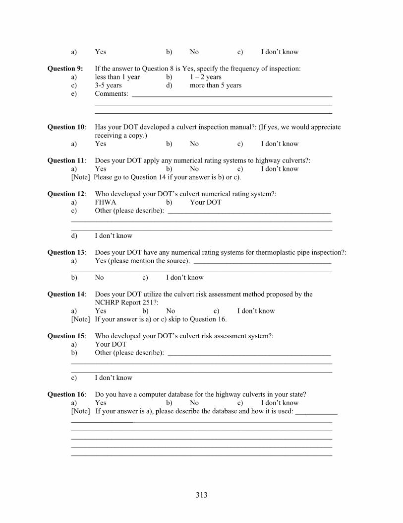
313
a) Yes b) No c) I don’t know
Question 9: If the answer to Question 8 is Yes, specify the frequency of inspection: a) less than 1 year b) 1 – 2 years c) 3-5 years d) more than 5 years e) Comments:
Question 10: Has your DOT developed a culvert inspection manual?: (If yes, we would appreciate receiving a copy.)
a) Yes b) No c) I don’t know
Question 11: Does your DOT apply any numerical rating systems to highway culverts?: a) Yes b) No c) I don’t know [Note] Please go to Question 14 if your answer is b) or c).
Question 12: Who developed your DOT’s culvert numerical rating system?: a) FHWA b) Your DOT c) Other (please describe): _____________________________________________ ________________________________________________________________________ ________________________________________________________________________ d) I don’t know
Question 13: Does your DOT have any numerical rating systems for thermoplastic pipe inspection?: a) Yes (please mention the source): ______________________________________ ________________________________________________________________________ b) No c) I don’t know
Question 14: Does your DOT utilize the culvert risk assessment method proposed by the NCHRP Report 251?: a) Yes b) No c) I don’t know [Note] If your answer is a) or c) skip to Question 16.
Question 15: Who developed your DOT’s culvert risk assessment system?: a) Your DOT b) Other (please describe): _____________________________________________ ________________________________________________________________________ ________________________________________________________________________
c) I don’t know
Question 16: Do you have a computer database for the highway culverts in your state? a) Yes b) No c) I don’t know [Note] If your answer is a), please describe the database and how it is used: ________ _________________ ________________________________________________________________________ ________________________________________________________________________ ________________________________________________________________________ ________________________________________________________________________

314
Question 17: How does your DOT decide when to replace each highway culvert? (Please mark all that applies). a) The age of the culvert. (Define):______________________________________________ b) The sum of numerical rating scores. c) The deflections experienced by the culvert. (Define):_____________________________ d) The degree of culvert material degradation. e) The roadway surface conditions over the culvert. f) I am not sure. g) Primarily by other factors (Please elaborate):
Question 18: Does your DOT or the subcontractor that you retain, utilize any special equipment to conduct visual inspections of culverts that are smaller than 4 ft in diameter or rise? a) Yes b) No c) I don’t know [Note] If your answer is a), please describe the equipment:
In addition to returning this survey form, we would appreciate receiving copies of any documents (manuals, reports, letters, …) utilized by your DOT that contain information related to the highway culvert inspection & risk assessment policies and procedures.
Ohio Research Institute for Transportation & the Environment (ORITE)Attention: Highway Culvert Inspection and Risk Assessment Survey Room 114, Stocker Center College of Engineering & Technology Ohio University, Athens, Ohio 45701-2979 Telephone: (740) 593-9547 Fax: (740) 593-0625 e-Mail: [email protected]: http://webce.ent.ohiou.edu/orite
Culvert Inspection Survey:
Name of Individual Completing the Survey: Title: Address:
Telephone Number: Email:
I would like to receive a copy of the survey results: Yes No
Thank you for your time and effort in completing this survey.

315
APPENDIX B: Proposed Culvert Rating System (Reinforced Concrete Culverts)
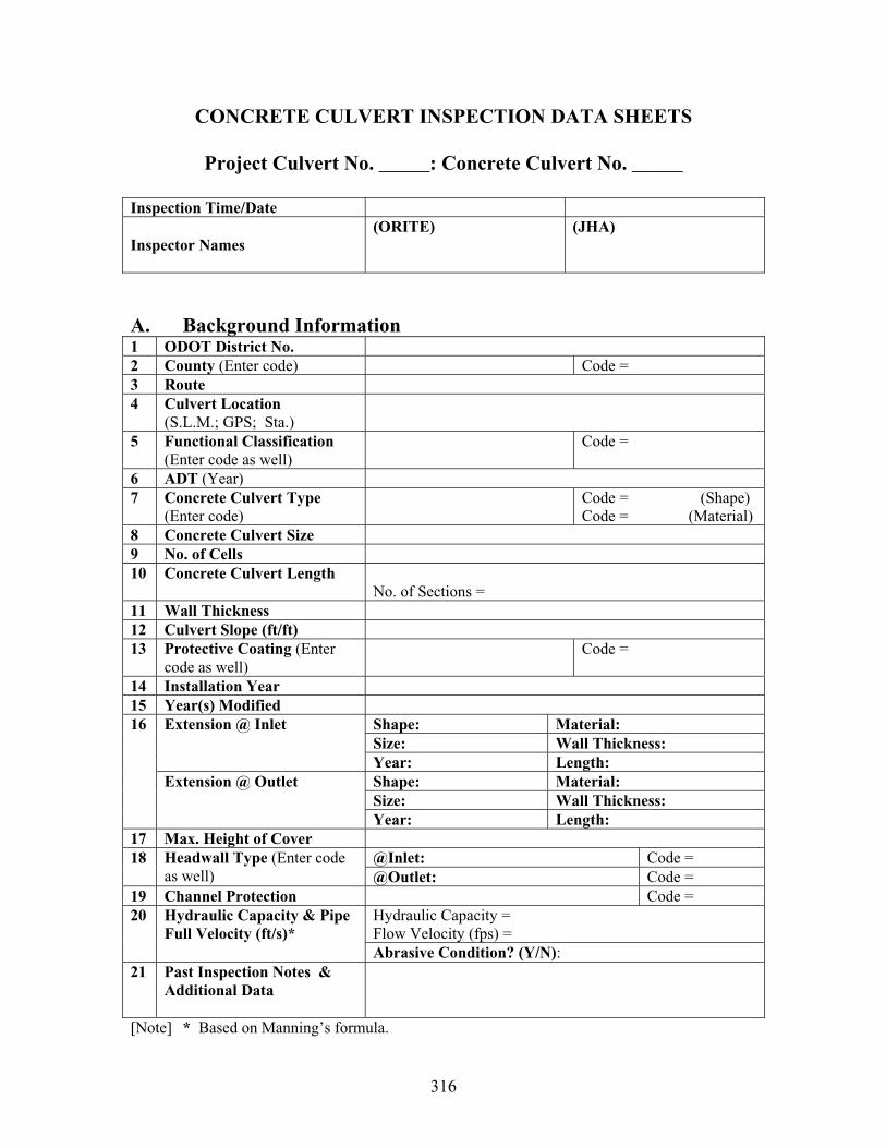
316
CONCRETE CULVERT INSPECTION DATA SHEETS
Project Culvert No. _____: Concrete Culvert No. _____
Inspection Time/Date
Inspector Names (ORITE) (JHA)
A. Background Information 1 ODOT District No. 2 County (Enter code) Code = 3 Route4 Culvert Location
(S.L.M.; GPS; Sta.)5 Functional Classification
(Enter code as well) Code =
6 ADT (Year)7 Concrete Culvert Type
(Enter code) Code = (Shape)
Code = (Material) 8 Concrete Culvert Size 9 No. of Cells 10 Concrete Culvert Length
No. of Sections = 11 Wall Thickness 12 Culvert Slope (ft/ft) 13 Protective Coating (Enter
code as well) Code =
14 Installation Year 15 Year(s) Modified
Shape: Material: Size: Wall Thickness:
Extension @ Inlet
Year: Length: Shape: Material: Size: Wall Thickness:
16
Extension @ Outlet
Year: Length: 17 Max. Height of Cover
@Inlet: Code = 18 Headwall Type (Enter code as well) @Outlet: Code =
19 Channel Protection Code = Hydraulic Capacity = Flow Velocity (fps) =
20 Hydraulic Capacity & Pipe Full Velocity (ft/s)*
Abrasive Condition? (Y/N):21 Past Inspection Notes &
Additional Data
[Note] * Based on Manning’s formula.
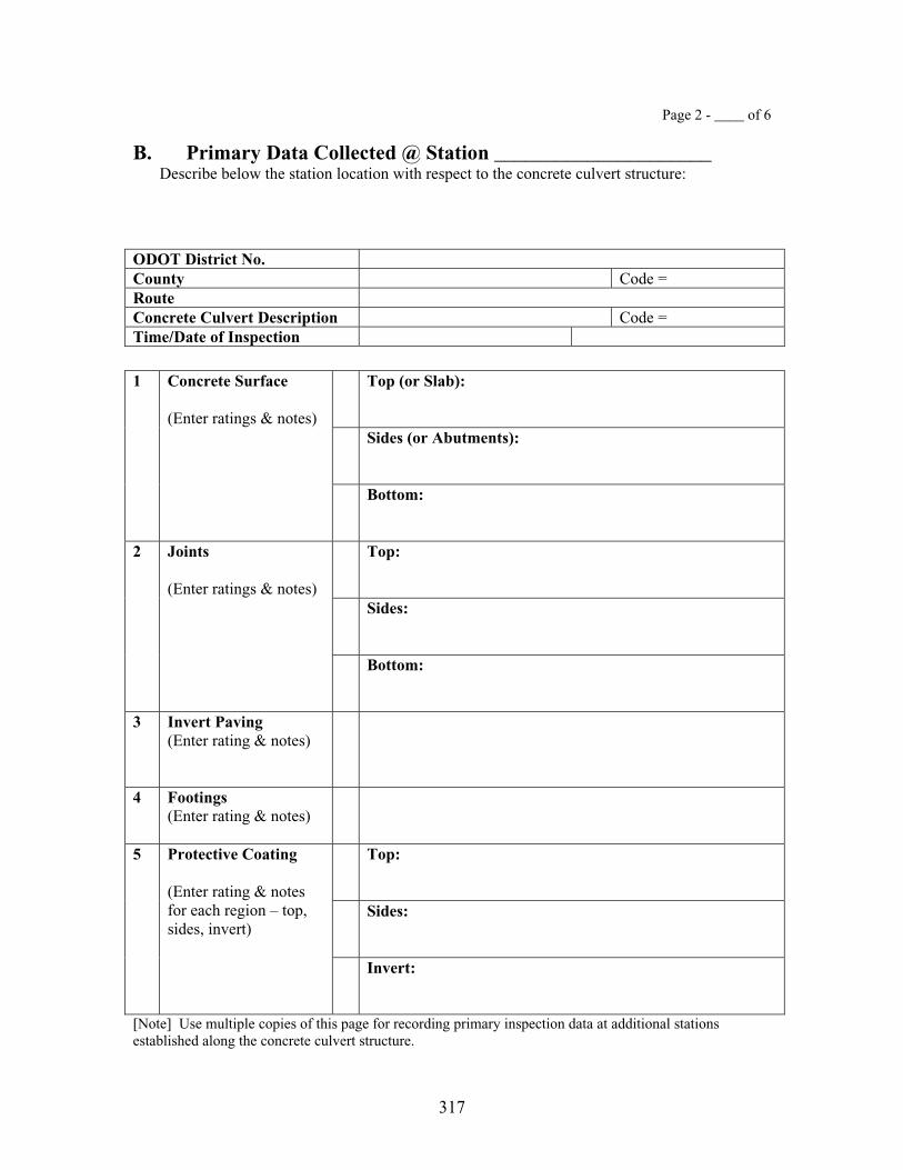
317
Page 2 - ____ of 6
B. Primary Data Collected @ Station _____________________ Describe below the station location with respect to the concrete culvert structure:
ODOT District No. County Code = RouteConcrete Culvert Description Code = Time/Date of Inspection
Top (or Slab):
Sides (or Abutments):
1 Concrete Surface
(Enter ratings & notes)
Bottom:
Top:
Sides:
2 Joints
(Enter ratings & notes)
Bottom:
3 Invert Paving (Enter rating & notes)
4 Footings (Enter rating & notes)
Top:
Sides:
5 Protective Coating
(Enter rating & notes for each region – top, sides, invert)
Invert:
[Note] Use multiple copies of this page for recording primary inspection data at additional stations established along the concrete culvert structure.

318
Page 3 of 6
B. Primary Data Collected – Continued
ODOT District No. County Code = RouteConcrete Culvert Description
Code =
Time/Date of Inspection
6 Inlet Condition (Enter rating & notes)
7 Outlet Condition (Enter rating & notes)
8 Slope & Settlement (including sagging) (Enter rating & notes)
9 Horizontal Alignment (Enter rating & notes)
10 Additional Data
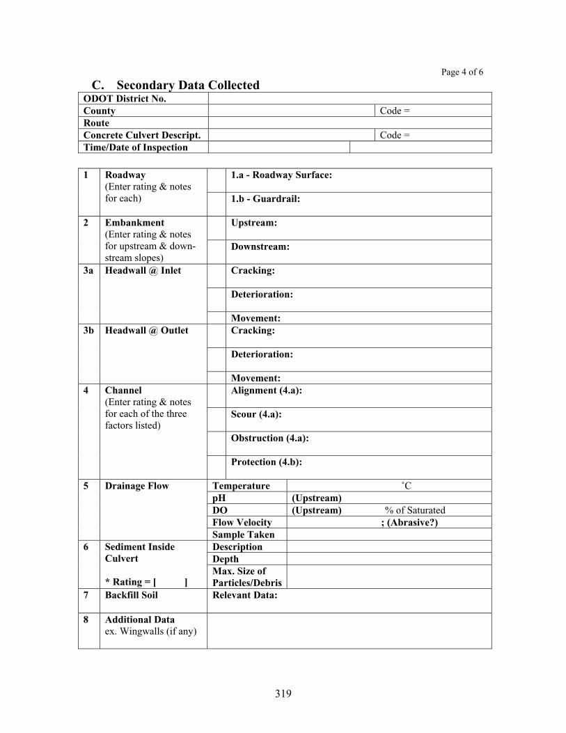
319
Page 4 of 6
C. Secondary Data Collected ODOT District No. County Code = RouteConcrete Culvert Descript. Code = Time/Date of Inspection
1.a - Roadway Surface: 1 Roadway (Enter rating & notes for each) 1.b - Guardrail:
Upstream: 2 Embankment(Enter rating & notes for upstream & down-stream slopes)
Downstream:
Cracking:
Deterioration:
3a Headwall @ Inlet
Movement: Cracking:
Deterioration:
3b Headwall @ Outlet
Movement: Alignment (4.a):
Scour (4.a):
Obstruction (4.a):
4 Channel (Enter rating & notes for each of the three factors listed)
Protection (4.b):
Temperature ˚CpH (Upstream) DO (Upstream) % of SaturatedFlow Velocity ; (Abrasive?)
5 Drainage Flow
Sample Taken Description Depth
6 Sediment Inside Culvert
* Rating = [ ] Max. Size of Particles/Debris
7 Backfill Soil Relevant Data:
8 Additional Data ex. Wingwalls (if any)

320
Page 5 of 6
D. Photographs Taken
ODOT District No. County Code = RouteConcrete Culvert Description Code = Time/Date of Inspection
Type of Camera Used Photographer’s Name Management of Pictures Taken
E. Level of Inspection
Components Inlet Section Outlet Section Main Barrel Level of Inspection: Specify --- X = Inspection from ends (no entry) M = Manned entry inspection V = Video inspection Type of Video Equipment Used
Additional Comments

321
Page 6 of 6
F. Field Sketches
ODOT District No. County Code = RouteConcrete Culvert Description
Code =
Time/Date of Inspection
Draw sketches in the space below to describe conditions encountered in the field (if necessary):
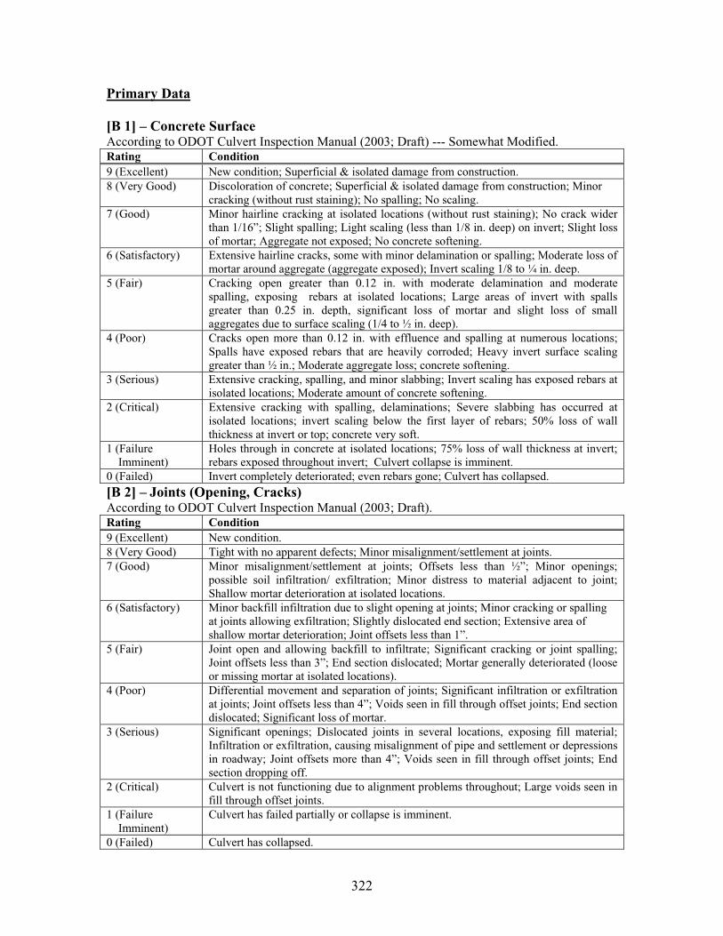
322
Primary Data
[B 1] – Concrete Surface According to ODOT Culvert Inspection Manual (2003; Draft) --- Somewhat Modified. Rating Condition 9 (Excellent) New condition; Superficial & isolated damage from construction. 8 (Very Good) Discoloration of concrete; Superficial & isolated damage from construction; Minor
cracking (without rust staining); No spalling; No scaling. 7 (Good) Minor hairline cracking at isolated locations (without rust staining); No crack wider
than 1/16”; Slight spalling; Light scaling (less than 1/8 in. deep) on invert; Slight loss of mortar; Aggregate not exposed; No concrete softening.
6 (Satisfactory) Extensive hairline cracks, some with minor delamination or spalling; Moderate loss of mortar around aggregate (aggregate exposed); Invert scaling 1/8 to ¼ in. deep.
5 (Fair) Cracking open greater than 0.12 in. with moderate delamination and moderate spalling, exposing rebars at isolated locations; Large areas of invert with spalls greater than 0.25 in. depth, significant loss of mortar and slight loss of small aggregates due to surface scaling (1/4 to ½ in. deep).
4 (Poor) Cracks open more than 0.12 in. with effluence and spalling at numerous locations; Spalls have exposed rebars that are heavily corroded; Heavy invert surface scaling greater than ½ in.; Moderate aggregate loss; concrete softening.
3 (Serious) Extensive cracking, spalling, and minor slabbing; Invert scaling has exposed rebars at isolated locations; Moderate amount of concrete softening.
2 (Critical) Extensive cracking with spalling, delaminations; Severe slabbing has occurred at isolated locations; invert scaling below the first layer of rebars; 50% loss of wall thickness at invert or top; concrete very soft.
1 (Failure Imminent)
Holes through in concrete at isolated locations; 75% loss of wall thickness at invert; rebars exposed throughout invert; Culvert collapse is imminent.
0 (Failed) Invert completely deteriorated; even rebars gone; Culvert has collapsed. [B 2] – Joints (Opening, Cracks) According to ODOT Culvert Inspection Manual (2003; Draft).Rating Condition 9 (Excellent) New condition. 8 (Very Good) Tight with no apparent defects; Minor misalignment/settlement at joints. 7 (Good) Minor misalignment/settlement at joints; Offsets less than ½”; Minor openings;
possible soil infiltration/ exfiltration; Minor distress to material adjacent to joint; Shallow mortar deterioration at isolated locations.
6 (Satisfactory) Minor backfill infiltration due to slight opening at joints; Minor cracking or spalling at joints allowing exfiltration; Slightly dislocated end section; Extensive area of shallow mortar deterioration; Joint offsets less than 1”.
5 (Fair) Joint open and allowing backfill to infiltrate; Significant cracking or joint spalling; Joint offsets less than 3”; End section dislocated; Mortar generally deteriorated (loose or missing mortar at isolated locations).
4 (Poor) Differential movement and separation of joints; Significant infiltration or exfiltration at joints; Joint offsets less than 4”; Voids seen in fill through offset joints; End section dislocated; Significant loss of mortar.
3 (Serious) Significant openings; Dislocated joints in several locations, exposing fill material; Infiltration or exfiltration, causing misalignment of pipe and settlement or depressions in roadway; Joint offsets more than 4”; Voids seen in fill through offset joints; End section dropping off.
2 (Critical) Culvert is not functioning due to alignment problems throughout; Large voids seen in fill through offset joints.
1 (Failure Imminent)
Culvert has failed partially or collapse is imminent.
0 (Failed) Culvert has collapsed.
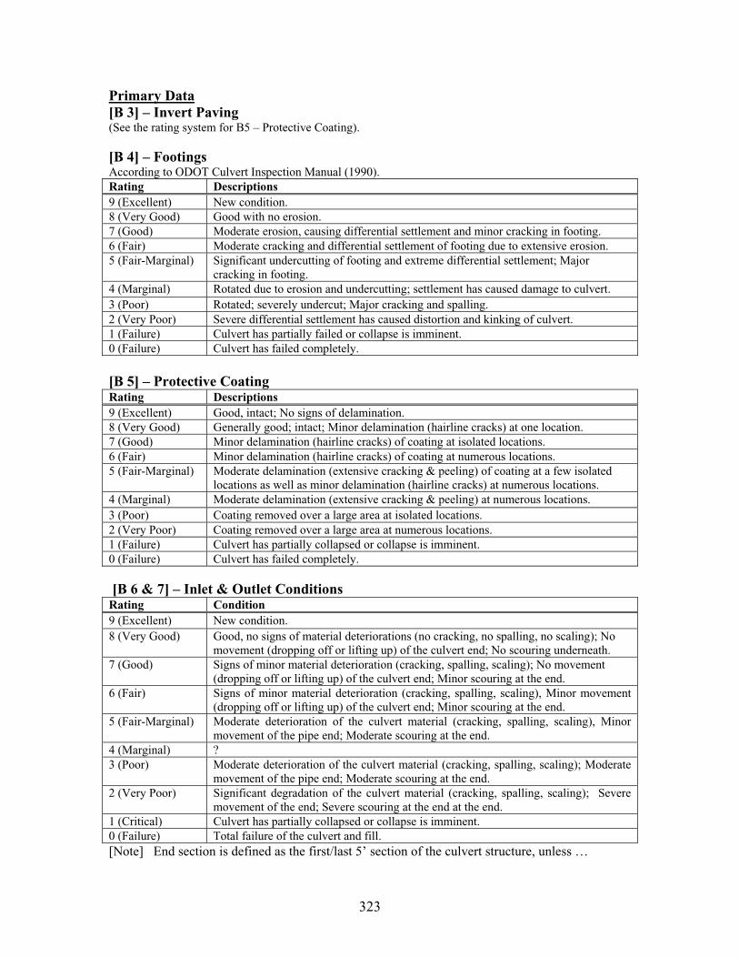
323
Primary Data[B 3] – Invert Paving (See the rating system for B5 – Protective Coating).
[B 4] – FootingsAccording to ODOT Culvert Inspection Manual (1990). Rating Descriptions 9 (Excellent) New condition. 8 (Very Good) Good with no erosion. 7 (Good) Moderate erosion, causing differential settlement and minor cracking in footing. 6 (Fair) Moderate cracking and differential settlement of footing due to extensive erosion. 5 (Fair-Marginal) Significant undercutting of footing and extreme differential settlement; Major
cracking in footing. 4 (Marginal) Rotated due to erosion and undercutting; settlement has caused damage to culvert. 3 (Poor) Rotated; severely undercut; Major cracking and spalling. 2 (Very Poor) Severe differential settlement has caused distortion and kinking of culvert. 1 (Failure) Culvert has partially failed or collapse is imminent. 0 (Failure) Culvert has failed completely.
[B 5] – Protective Coating Rating Descriptions 9 (Excellent) Good, intact; No signs of delamination. 8 (Very Good) Generally good; intact; Minor delamination (hairline cracks) at one location. 7 (Good) Minor delamination (hairline cracks) of coating at isolated locations. 6 (Fair) Minor delamination (hairline cracks) of coating at numerous locations. 5 (Fair-Marginal) Moderate delamination (extensive cracking & peeling) of coating at a few isolated
locations as well as minor delamination (hairline cracks) at numerous locations. 4 (Marginal) Moderate delamination (extensive cracking & peeling) at numerous locations. 3 (Poor) Coating removed over a large area at isolated locations. 2 (Very Poor) Coating removed over a large area at numerous locations. 1 (Failure) Culvert has partially collapsed or collapse is imminent. 0 (Failure) Culvert has failed completely.
[B 6 & 7] – Inlet & Outlet Conditions Rating Condition 9 (Excellent) New condition. 8 (Very Good) Good, no signs of material deteriorations (no cracking, no spalling, no scaling); No
movement (dropping off or lifting up) of the culvert end; No scouring underneath. 7 (Good) Signs of minor material deterioration (cracking, spalling, scaling); No movement
(dropping off or lifting up) of the culvert end; Minor scouring at the end. 6 (Fair) Signs of minor material deterioration (cracking, spalling, scaling), Minor movement
(dropping off or lifting up) of the culvert end; Minor scouring at the end. 5 (Fair-Marginal) Moderate deterioration of the culvert material (cracking, spalling, scaling), Minor
movement of the pipe end; Moderate scouring at the end. 4 (Marginal) ? 3 (Poor) Moderate deterioration of the culvert material (cracking, spalling, scaling); Moderate
movement of the pipe end; Moderate scouring at the end. 2 (Very Poor) Significant degradation of the culvert material (cracking, spalling, scaling); Severe
movement of the end; Severe scouring at the end at the end. 1 (Critical) Culvert has partially collapsed or collapse is imminent. 0 (Failure) Total failure of the culvert and fill. [Note] End section is defined as the first/last 5’ section of the culvert structure, unless …

324
Primary Data
[B 8] – Slope & SettlementAccording to ODOT Culvert Inspection Manual (2003; Draft) – Modified slightly. Rating Descriptions 9 (Excellent) Like new; Good; uniform slope; no settlement. 8 (Very Good) Minor settlement at one location. 7 (Good) Minor settlement at isolated locations; Offsets at joints less than ½”; Ponding water
less than 1” deep. 6 (Fair) Minor settlement at numerous locations along the culvert; Ponding water less than 3”
deep.5 (Fair-Marginal) Moderate settlement at one location; Offsets at joints less than 3”; Ponding water less
than 5.” 4 (Marginal) Moderate settlement of the culvert; Ponding water less than 6” deep; 4 or more
sections with offsets less than 3”; End section dislocated and about to drop off. 3 (Poor) Severe settlement in one section; Ponding water deeper than 6”; End section dropping
off; 4 or more sections with offsets less than 4.” 2 (Very Poor) Culvert not functioning due to sever settlement problem; Upstream end cannot be
seen from the downstream end; Ponding of water more than 50% of the pipe length. 1 (Critical) Culvert has partially collapsed. 0 (Failure) Culvert has collapsed completely.
[B 9] – Horizontal AlignmentRating Descriptions 9 (Excellent) New condition. 8 (Very Good) Good: no horizontal misalignment. 7 (Good) Generally good; minor misalignment at one location; No backfill infiltration problem
exists yet. 6 (Fair) Generally fair; minor misalignment at isolated locations; No backfill infiltration
problem exists yet. 5 (Fair-Marginal) Moderate misalignment at one location; Minor backfill infiltration may be possible
there.4 (Marginal) Moderate misalignment at isolated locations; Minor backfill infiltration may be
possible. 3 (Poor) Significant misalignment of the culvert at isolated locations; End section drop-off
has occurred; Minor backfill infiltration is observed. 2 (Very Poor) Culvert not functioning due to severe alignment problems throughout; Signs of
backfill infiltration seen at more than a few locations. 1 (Critical) Culvert has failed partially or collapse is imminent. 0 (Failure) Culvert has collapsed completely.

325
Secondary Data
[C 1.a] – Roadway Surface According to ODOT Culvert Inspection Manual (2003; Draft) – Modified somewhat. Rating Descriptions 9 (Excellent) New condition; No defects noticed. 8 (Very good) Minor hairline cracks; No dip (settlement). 7 (Good) Minor hairline cracks; Minor scaling; Very small potholes; No dip (settlement). 6 (Satisfactory) Minor potholes; Minor dip (settlement); Cracking with width less than 0.1 in;
Transverse cracks do not extend all the way across the roadway. 5 (Fair) Moderate size potholes; Minor spalling; Minor dip accompanied with a few cracks;
Transverse cracks are wider than 0.1 in and extend all the way across the roadway. 4 (Poor) Moderate dip in roadway; Numerous cracks on the surface layer (starting to break up
the pavement). 3 (Serious) Significant dip; Extensive cracking of roadway surface (breaking up the pavement);
Repairs required immediately. 2 (Critical) Significant dip; Extensive cracking of roadway surface, damages on the pavement
surface layer, posing potential danger to drivers; Embankment washed out next to pavement.
1 (Closed) Road closed; Impending pavement and/or embankment failure. 0 (Failed) Roadway is closed to traffic; Embankment and/or pavement failed. - 1 Cannot be rated; Roadway is still under construction.
[C 1.b] – Guardrail According to ODOT Culvert Inspection Manual (2003; Draft) Rating Descriptions 9 (Excellent) New condition; Guardrail free from any defects. 8 (Very good) Minor discoloration; No noteworthy deficiencies noted; 7 (Good) Minor deficiencies noted within 100’ of culvert; No bolts missing; Misalignment of 1
or 2 guardrail posts. 6 (Satisfactory) Minor collision damage; Up to 10% loss of section of posts due to decay; Guardrail
position is noticeably higher or lower than the standard 27”; Guardrail panels are rusted; Several bolts are missing; Misalignment of up to 3 guardrail posts.
5 (Fair) Moderate collision damage; Up to 20% loss of section of posts due to decay; Guardrail position is noticeably higher or lower than the standard 27”; Guardrail panels are rusted; Several bolts are missing; Misalignment of up to 5 guardrail posts.
4 (Poor) Major collision damage; Up to 30% loss of section of posts due to decay; Guardrail position is noticeably higher or lower than the standard 27”; Guardrail panels are rusted; Several bolts are missing; Misalignment of up to 6 guardrail posts.
3 (Serious) Major collision damage; Up to 50% loss of section of posts due to decay; Guardrail position is noticeably higher or lower than the standard 27”; Guardrail panels are rusted; Several bolts are missing; Misalignment of more than 6 guardrail posts.
2 (Critical) Guardrail is not functioning; Up to 90% of decay of posts. 1 (Closed) Guardrail has collapsed partially. 0 (Failed) Guardrail has collapsed completely. - 1 Cannot be rated; Guardrail is still under construction.
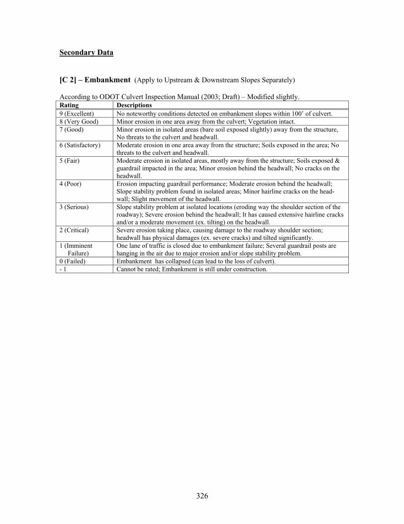
326
Secondary Data
[C 2] – Embankment (Apply to Upstream & Downstream Slopes Separately)
According to ODOT Culvert Inspection Manual (2003; Draft) – Modified slightly. Rating Descriptions 9 (Excellent) No noteworthy conditions detected on embankment slopes within 100’ of culvert. 8 (Very Good) Minor erosion in one area away from the culvert; Vegetation intact. 7 (Good) Minor erosion in isolated areas (bare soil exposed slightly) away from the structure,
No threats to the culvert and headwall. 6 (Satisfactory) Moderate erosion in one area away from the structure; Soils exposed in the area; No
threats to the culvert and headwall. 5 (Fair) Moderate erosion in isolated areas, mostly away from the structure; Soils exposed &
guardrail impacted in the area; Minor erosion behind the headwall; No cracks on the headwall.
4 (Poor) Erosion impacting guardrail performance; Moderate erosion behind the headwall; Slope stability problem found in isolated areas; Minor hairline cracks on the head-wall; Slight movement of the headwall.
3 (Serious) Slope stability problem at isolated locations (eroding way the shoulder section of the roadway); Severe erosion behind the headwall; It has caused extensive hairline cracks and/or a moderate movement (ex. tilting) on the headwall.
2 (Critical) Severe erosion taking place, causing damage to the roadway shoulder section; headwall has physical damages (ex. severe cracks) and tilted significantly.
1 (Imminent Failure)
One lane of traffic is closed due to embankment failure; Several guardrail posts are hanging in the air due to major erosion and/or slope stability problem.
0 (Failed) Embankment has collapsed (can lead to the loss of culvert). - 1 Cannot be rated; Embankment is still under construction.
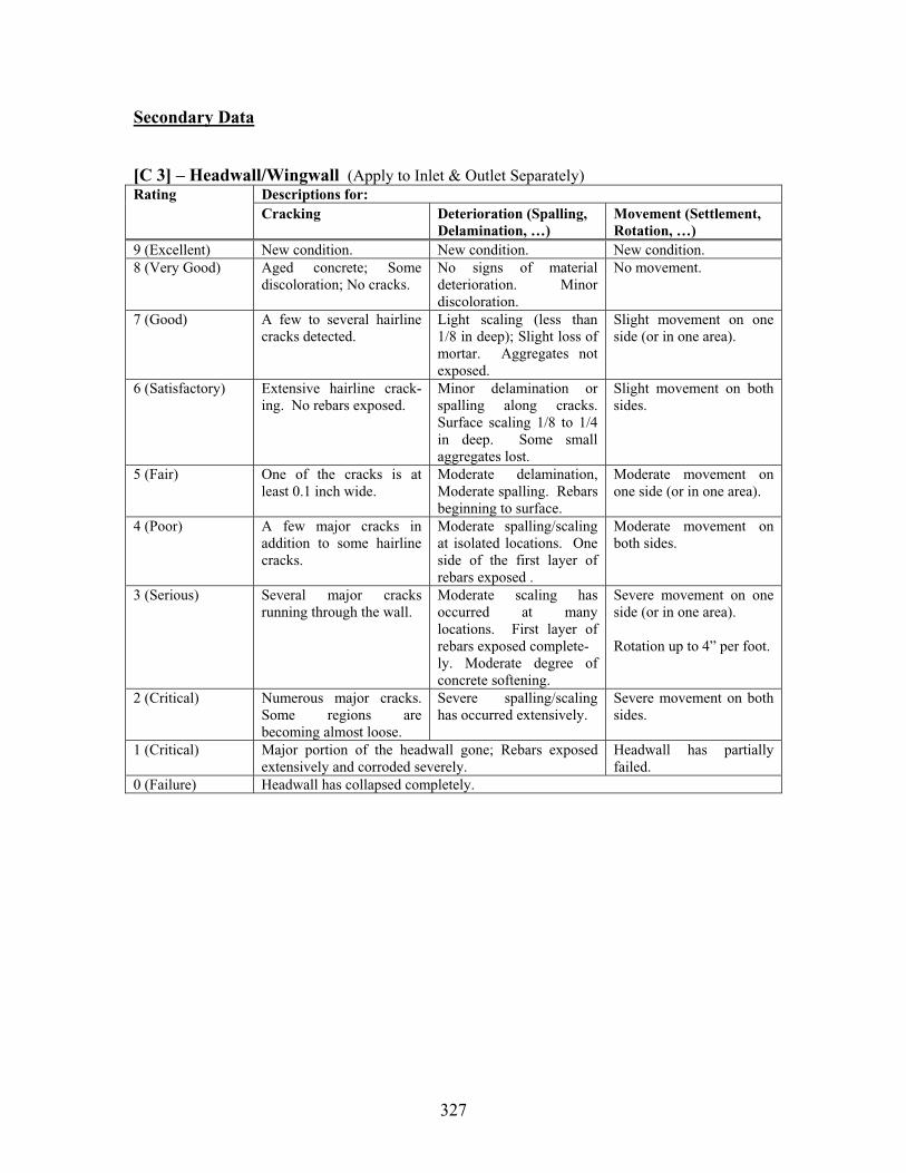
327
Secondary Data
[C 3] – Headwall/Wingwall (Apply to Inlet & Outlet Separately)Descriptions for: Rating Cracking Deterioration (Spalling,
Delamination, …) Movement (Settlement, Rotation, …)
9 (Excellent) New condition. New condition. New condition. 8 (Very Good) Aged concrete; Some
discoloration; No cracks. No signs of material deterioration. Minor discoloration.
No movement.
7 (Good) A few to several hairline cracks detected.
Light scaling (less than 1/8 in deep); Slight loss of mortar. Aggregates not exposed.
Slight movement on one side (or in one area).
6 (Satisfactory) Extensive hairline crack-ing. No rebars exposed.
Minor delamination or spalling along cracks. Surface scaling 1/8 to 1/4 in deep. Some small aggregates lost.
Slight movement on both sides.
5 (Fair) One of the cracks is at least 0.1 inch wide.
Moderate delamination, Moderate spalling. Rebars beginning to surface.
Moderate movement on one side (or in one area).
4 (Poor) A few major cracks in addition to some hairline cracks.
Moderate spalling/scaling at isolated locations. One side of the first layer of rebars exposed .
Moderate movement on both sides.
3 (Serious) Several major cracks running through the wall.
Moderate scaling has occurred at many locations. First layer of rebars exposed complete- ly. Moderate degree of concrete softening.
Severe movement on one side (or in one area).
Rotation up to 4” per foot.
2 (Critical) Numerous major cracks. Some regions are becoming almost loose.
Severe spalling/scaling has occurred extensively.
Severe movement on both sides.
1 (Critical) Major portion of the headwall gone; Rebars exposed extensively and corroded severely.
Headwall has partially failed.
0 (Failure) Headwall has collapsed completely.
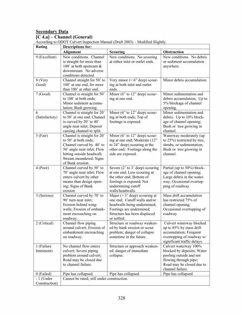
328
Secondary Data[C 4.a] – Channel (General) According to ODOT Culvert Inspection Manual (Draft 2003) – Modified Slightly.
Descriptions for: Rating Alignment Scouring Obstruction
9 (Excellent) New conditions. Channel is straight for more than 100’ at both upstream & downstream. No adverse conditions detected.
New conditions. No scouring at either inlet or outlet ends.
New conditions. No debris or sediment accumulation anywhere.
8 (Very Good)
Channel straight for 50’ to 100’ at one end, for more than 100’ at other end.
Very minor (< 6” deep) scour-ing at both inlet and outlet ends.
Minor debris accumulation.
7 (Good) Channel is straight for 50’ to 100’ at both ends; Minor sediment accumu-lation; Bush growing.
Minor (6” to 12” deep) scour-ing at one end.
Minor sedimentation and debris accumulation; Up to 5% blockage of channel opening.
6(Satisfactory)
Channel is straight for 20’ to 50’ at one end; Channel is curved by 20˚ to 40˚angle near inlet; Deposit causing channel to split.
Minor (6” to 12” deep) scour-ing at both ends; Top of footings is exposed.
Minor sedimentation and debris. Up to 10% block-age of channel opening; Bush or tree growing in channel.
5 (Fair) Channel is straight for 20’ to 50’ at both ends; Channel curved by 40˚ to 50˚ angle near inlet; Flow hitting outside headwall; Stream meandered; Signs of Bank erosion.
Minor (6” to 12” deep) scour-ing at one end; Moderate (12” to 24” deep) scouring at the other end; Footings along the side are exposed.
Waterway moderately (up to 25%) restricted by tree, shrubs, or sedimentation; Bush or tree growing in channel.
4 (Poor) Channel curved by 50˚ to 70˚ angle near inlet; Flow enters culvert by other means than design open-ing; Signs of Bank erosion.
Severe (2’ to 3’ deep) scouring at one end; Less scouring at the other end; Bottom of footings is exposed; Not undermining cutoff walls/headwalls.
Partial (up to 50%) block-age of channel opening; Large debris in the water-way; Occasional overtop-ping of roadway.
3 (Serious) Channel curved by 70˚ to 90˚ turn near inlet; Erosion behind wing-walls; Erosion of embank-ment encroaching on roadway.
Major (> 3’ deep) scouring at one end; Cutoff walls and/or headwalls being undermined; Footings are undermined; Structure has been displaced or settled.
Mass drift accumulation has restricted 75% of channel opening; Occasional overtopping of roadway.
2 (Critical) Channel flow piping around culvert; Erosion of embankment encroaching on roadway.
Structure or roadway weaken-ed by bank erosion or scour problem; danger of collapse sometime in the future.
Culvert waterway blocked up to 85% by mass drift accumulation; Frequent overtopping of roadway w/ significant traffic delays.
1 (Failure Imminent)
No channel flow enters culvert; Severe piping problem around culvert; Road may be closed due to channel failure.
Structure or approach weaken-ed; danger of immediate collapse.
Culvert waterway 100% blocked by deposits; Water pooling outside and not flowing through pipe; Road may be closed due to channel failure.
0 (Failed) Pipe has collapsed. Pipe has collapsed. Pipe has collapsed. - 1 (Under Construction)
Cannot be rated; still under construction.
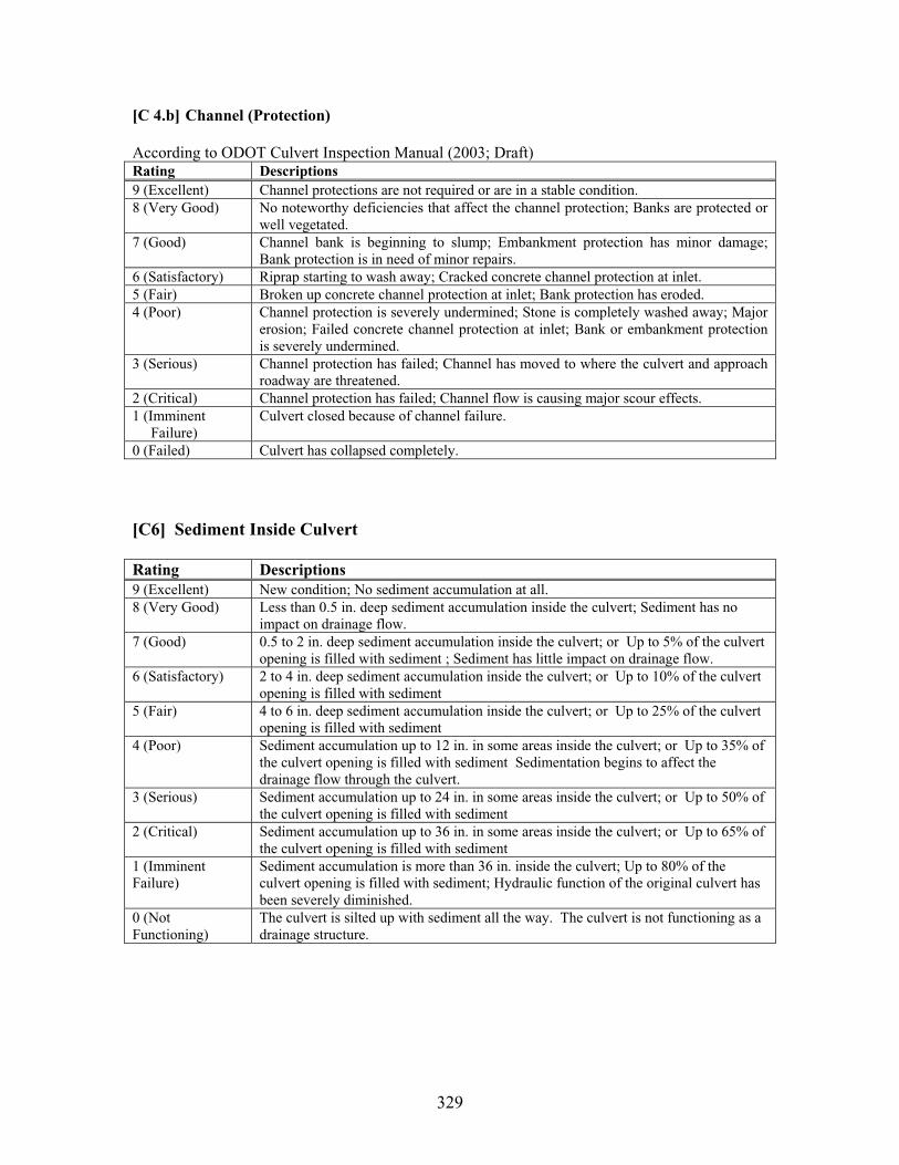
329
[C 4.b] Channel (Protection)
According to ODOT Culvert Inspection Manual (2003; Draft) Rating Descriptions 9 (Excellent) Channel protections are not required or are in a stable condition. 8 (Very Good) No noteworthy deficiencies that affect the channel protection; Banks are protected or
well vegetated. 7 (Good) Channel bank is beginning to slump; Embankment protection has minor damage;
Bank protection is in need of minor repairs. 6 (Satisfactory) Riprap starting to wash away; Cracked concrete channel protection at inlet. 5 (Fair) Broken up concrete channel protection at inlet; Bank protection has eroded. 4 (Poor) Channel protection is severely undermined; Stone is completely washed away; Major
erosion; Failed concrete channel protection at inlet; Bank or embankment protection is severely undermined.
3 (Serious) Channel protection has failed; Channel has moved to where the culvert and approach roadway are threatened.
2 (Critical) Channel protection has failed; Channel flow is causing major scour effects. 1 (Imminent Failure)
Culvert closed because of channel failure.
0 (Failed) Culvert has collapsed completely.
[C6] Sediment Inside Culvert
Rating Descriptions 9 (Excellent) New condition; No sediment accumulation at all. 8 (Very Good) Less than 0.5 in. deep sediment accumulation inside the culvert; Sediment has no
impact on drainage flow. 7 (Good) 0.5 to 2 in. deep sediment accumulation inside the culvert; or Up to 5% of the culvert
opening is filled with sediment ; Sediment has little impact on drainage flow. 6 (Satisfactory) 2 to 4 in. deep sediment accumulation inside the culvert; or Up to 10% of the culvert
opening is filled with sediment 5 (Fair) 4 to 6 in. deep sediment accumulation inside the culvert; or Up to 25% of the culvert
opening is filled with sediment 4 (Poor) Sediment accumulation up to 12 in. in some areas inside the culvert; or Up to 35% of
the culvert opening is filled with sediment Sedimentation begins to affect the drainage flow through the culvert.
3 (Serious) Sediment accumulation up to 24 in. in some areas inside the culvert; or Up to 50% of the culvert opening is filled with sediment
2 (Critical) Sediment accumulation up to 36 in. in some areas inside the culvert; or Up to 65% of the culvert opening is filled with sediment
1 (Imminent Failure)
Sediment accumulation is more than 36 in. inside the culvert; Up to 80% of the culvert opening is filled with sediment; Hydraulic function of the original culvert has been severely diminished.
0 (Not Functioning)
The culvert is silted up with sediment all the way. The culvert is not functioning as a drainage structure.

330
APPENDIX C: Proposed Culvert Rating System (Corrugated Metal Culverts)
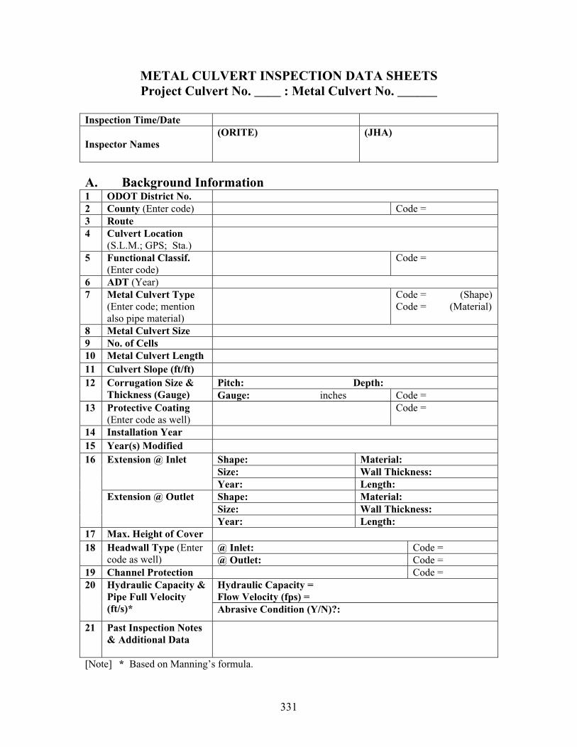
331
METAL CULVERT INSPECTION DATA SHEETS Project Culvert No. ____ : Metal Culvert No. ______
Inspection Time/Date
Inspector Names (ORITE) (JHA)
A. Background Information 1 ODOT District No. 2 County (Enter code) Code = 3 Route 4 Culvert Location
(S.L.M.; GPS; Sta.) 5 Functional Classif.
(Enter code)Code =
6 ADT (Year)7 Metal Culvert Type
(Enter code; mention also pipe material)
Code = (Shape) Code = (Material)
8 Metal Culvert Size 9 No. of Cells 10 Metal Culvert Length 11 Culvert Slope (ft/ft)
Pitch: Depth:12 Corrugation Size & Thickness (Gauge) Gauge: inches Code =
13 Protective Coating (Enter code as well)
Code =
14 Installation Year15 Year(s) Modified
Shape: Material: Size: Wall Thickness:
Extension @ Inlet
Year: Length: Shape: Material: Size: Wall Thickness:
16
Extension @ Outlet
Year: Length: 17 Max. Height of Cover
@ Inlet: Code = 18 Headwall Type (Entercode as well) @ Outlet: Code =
19 Channel Protection Code = Hydraulic Capacity = Flow Velocity (fps) =
20 Hydraulic Capacity & Pipe Full Velocity (ft/s)* Abrasive Condition (Y/N)?:
21 Past Inspection Notes & Additional Data
[Note] * Based on Manning’s formula.

332
Page 2 - _____ of 6
B. Primary Data Collected @ Station _____________________ Describe below the station location with respect to the metal pipe culvert structure:
ODOT District No. County Code = RouteMetal Culvert Description Code = Time/Date of Inspection
1 Span & Rise Dimension
Span = Rise =
2 Other Dimensions (ex. top-arc mid ordinate, …)
3 Shape Observations (Enter rating & note)
4 Deflection (Enter rating & note)
Top:
Sides:
Metal Plate
(Enter ratings & notes for each region – top, sides, and invert) Invert:
5
Prospector’s Pick Observation
Top:
Sides:
6 Joints & Seams
(Enter ratings & notes for each region – top, sides, invert) Invert:
7 Protective Coating (Enter rating & notes)
8 Invert Paving (Enter rating & notes)
9 Footings (Enter rating & notes)
[Note] Use multiple copies of this page for recording primary inspection data at additional stations established along the metal culvert structure.

333
Page 3 of 6
B. Primary Data Collected – Continued
ODOT District No. County Code = RouteMetal Culvert Description Code = Time/Date of Inspection
10 Inlet Condition (Enter rating & notes)
11 Outlet Condition (Enter rating & notes)
12 Slope & Settlement (including sagging) (Enter rating & notes)
13 Horizontal Alignment(Enter rating & notes)
14 Additional Data

334
Page 4 of 6
C. Secondary Data Collected ODOT District No. County Code = RouteMetal Culvert Description Code = Time/Date of Inspection
Surface (1.a): 1 Roadway Surface (Enter rating & notes for each item) Guardrail (1.b):
Upstream: 2 Embankment (Enter rating & notes for up-stream and downstream side slopes)
Downstream:
Cracking:
Deterioration:
3a Headwall @ Inlet
(Enter rating & notes for each category)
Movement:
Cracking:
Deterioration:
3b Headwall @ Outlet
(Enter rating & notes for each category)
Movement:
Alignment (4.a):
Scour (4.a):
Obstruction (4.a):
4 Channel
(Outside the culvert; Enter rating & notes for each of the three factors listed)
Protection (4.b):
Temperature (Upstream): ˚CpH (Upstream): DO (Upstream): % of SaturatedFlow Velocity (Abrasive?)
5 Drainage Flow
Sample Taken Description
Depth
6 Sediment Inside Culvert
* Rating = [ ] Max. Size of Particles/Debris
7 Backfill Soil Any Relevant Data:
8 Metal Plate Coupons Taken
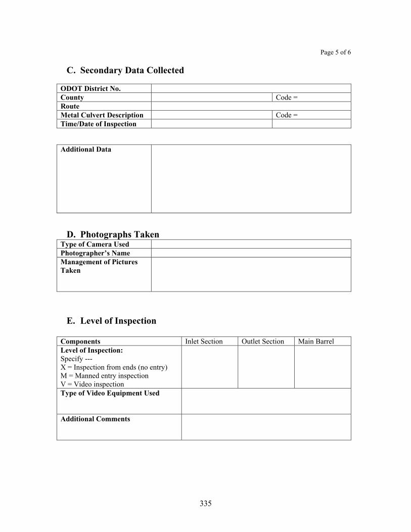
335
Page 5 of 6
C. Secondary Data Collected
ODOT District No. County Code = RouteMetal Culvert Description Code = Time/Date of Inspection
Additional Data
D. Photographs Taken Type of Camera Used Photographer’s Name Management of Pictures Taken
E. Level of Inspection
Components Inlet Section Outlet Section Main Barrel Level of Inspection: Specify --- X = Inspection from ends (no entry) M = Manned entry inspection V = Video inspection Type of Video Equipment Used
Additional Comments

336
Page 6 of 6
F. Field Sketches
ODOT District No. County Code = RouteMetal Culvert Description Code = Time/Date of Inspection
Draw sketches in the space below to describe conditions encountered in the field (if necessary):
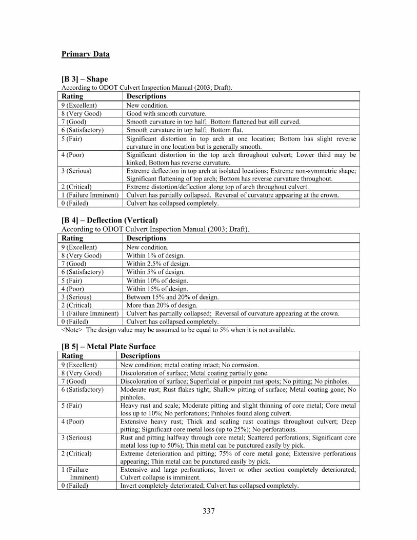
337
Primary Data
[B 3] – Shape According to ODOT Culvert Inspection Manual (2003; Draft). Rating Descriptions 9 (Excellent) New condition. 8 (Very Good) Good with smooth curvature. 7 (Good) Smooth curvature in top half; Bottom flattened but still curved. 6 (Satisfactory) Smooth curvature in top half; Bottom flat. 5 (Fair) Significant distortion in top arch at one location; Bottom has slight reverse
curvature in one location but is generally smooth. 4 (Poor) Significant distortion in the top arch throughout culvert; Lower third may be
kinked; Bottom has reverse curvature. 3 (Serious) Extreme deflection in top arch at isolated locations; Extreme non-symmetric shape;
Significant flattening of top arch; Bottom has reverse curvature throughout. 2 (Critical) Extreme distortion/deflection along top of arch throughout culvert. 1 (Failure Imminent) Culvert has partially collapsed. Reversal of curvature appearing at the crown. 0 (Failed) Culvert has collapsed completely.
[B 4] – Deflection (Vertical) According to ODOT Culvert Inspection Manual (2003; Draft). Rating Descriptions 9 (Excellent) New condition. 8 (Very Good) Within 1% of design. 7 (Good) Within 2.5% of design. 6 (Satisfactory) Within 5% of design. 5 (Fair) Within 10% of design. 4 (Poor) Within 15% of design. 3 (Serious) Between 15% and 20% of design. 2 (Critical) More than 20% of design. 1 (Failure Imminent) Culvert has partially collapsed; Reversal of curvature appearing at the crown. 0 (Failed) Culvert has collapsed completely. <Note> The design value may be assumed to be equal to 5% when it is not available.
[B 5] – Metal Plate SurfaceRating Descriptions 9 (Excellent) New condition; metal coating intact; No corrosion. 8 (Very Good) Discoloration of surface; Metal coating partially gone. 7 (Good) Discoloration of surface; Superficial or pinpoint rust spots; No pitting; No pinholes. 6 (Satisfactory) Moderate rust; Rust flakes tight; Shallow pitting of surface; Metal coating gone; No
pinholes. 5 (Fair) Heavy rust and scale; Moderate pitting and slight thinning of core metal; Core metal
loss up to 10%; No perforations; Pinholes found along culvert. 4 (Poor) Extensive heavy rust; Thick and scaling rust coatings throughout culvert; Deep
pitting; Significant core metal loss (up to 25%); No perforations. 3 (Serious) Rust and pitting halfway through core metal; Scattered perforations; Significant core
metal loss (up to 50%); Thin metal can be punctured easily by pick. 2 (Critical) Extreme deterioration and pitting; 75% of core metal gone; Extensive perforations
appearing; Thin metal can be punctured easily by pick. 1 (Failure Imminent)
Extensive and large perforations; Invert or other section completely deteriorated; Culvert collapse is imminent.
0 (Failed) Invert completely deteriorated; Culvert has collapsed completely.

338
Primary Data
[B 6] – Joints & Seams According to ODOT Culvert Inspection Manual (1990). Rating Descriptions 9 (Excellent) New condition. 8 (Very Good) Good condition; Minor discoloration; Light surface rust around bolt holes due to
loss of metal coating. 7 (Good) Rust scale around bolt holes; Minor cracking at a few bolt holes; Minor (< 1/8”)
joint or seam openings; Seepage infiltration (dripping water droplets) noted; More than 2 missing bolts per row.
6 (Satisfactory) Minor cracking all along one seam; Joint openings (up to ¼”) with evidence of seepage infiltration and slight backfill infiltration; Superficial rusting of the plates & bolts; More than 4 missing bolts per row.
5 (Fair) Moderate cracking at bolt holes along a seam in one section; Backfill being lost through seam or joint, causing slight deflection; Moderate rusting of plates & bolts; More than 6 missing bolts per row.
4 (Poor) Moderate cracking all along one seam; Backfill infiltration causing major deflection; Moderate rusting of plates & bolts at the joint; Partial cocked and cusped seams; 10% of bolts missing along seams.
3 (Serious) Seam cracked 3 inches on each side of bolt holes along culvert; Longitudinal cocked & cusped seams; Backfill infiltrating.
2 (Critical) Seam cracked from bolt to bolt down at least one seam. Heavy rusting of plates & bolts; Significant amounts of backfill infiltration.
1 (Failure Imminent) Seam failed totally; Backfill exposed; Water flowing out of the culvert. 0 (Failed) Culvert has collapsed completely.
[B 7] – Protective CoatingRating Descriptions 9 (Excellent) New condition; Intact; No signs of delamination. 8 (Very Good) Mostly intact; Minor delamination (hairline cracks) at one location. 7 (Good) Minor delamination (hairline cracks) of coating at isolated locations. 6 (Fair) Minor delamination (hairline cracks) of coating at numerous locations. 5 (Fair-Marginal) Moderate delamination (extensive cracking & peeling) of coating at a few isolated
locations as well as minor delamination (hairline cracks) at numerous locations. 4 (Marginal) Moderate delamination (extensive cracking & peeling) at numerous locations. 3 (Poor) Coating removed over a large area at isolated locations.
2 (Very Poor) Coating removed over a large area at numerous locations. 1 (Failure Imminent)
Culvert has partially collapsed or collapse is imminent.
0 (Failure) Culvert has failed completely.
[B 8] – Invert Paving (See the rating system for B7 - Protective Coating).

339
Primary Data
[B 9] – Footings According to ODOT Culvert Inspection Manual (1990). Rating Descriptions 9 (Excellent) New condition. 8 (Very Good) Good with no erosion. 7 (Good) Moderate erosion, causing differential settlement and minor cracking in footing. 6 (Fair) Moderate cracking and differential settlement of footing due to extensive erosion. 5 (Fair-Marginal) Significant undercutting of footing and extreme differential settlement; Major
cracking in footing. 4 (Marginal) Rotated due to erosion and undercutting; Settlement has caused damage to culvert. 3 (Poor) Rotated; severely undercut; Major cracking and spalling. 2 (Very Poor) Severe differential settlement has caused distortion and kinking of culvert. 1 (Failure Imminent)
Culvert has partially failed or the failure is imminent.
0 (Failure) Culvert has failed completely.

340
Primary Data
[B 10 & 11] – Inlet & Outlet Conditions Rating Descriptions 9 (Excellent) New condition. 8 (Very Good) Slight discoloration; No signs of corrosion; No pitting; No damage on the culvert end
from falling/moving debris; No movement (dropping off or lifting up) of the culvert end; No scouring underneath.
7 (Good) Signs of light corrosion; Slight pitting; No damage on the culvert end; No movement (dropping off or lifting up) of the culvert end; No scouring underneath.
6 (Fair) Signs of light material deterioration (corrosion, pitting); A few small pinholes/ perforations; culvert end slightly damaged; Minor movement (dropping off or lifting up) of the culvert end; Minor scouring at the end.
5 (Fair-Marginal) Moderate deterioration (corrosion, pitting) of the culvert material; Small perforations at several isolated places; Culvert end moderately damaged; Minor movement of the culvert end; Moderate scouring at the end.
4 (Marginal) Moderate deterioration of the culvert material; Medium-size perforations at numerous locations; Minor movement of the culvert end; Moderate scouring at the end and/or underneath the culvert.
3 (Poor) Severe deterioration (corrosion, pitting) of the culvert material; Large perforations; Moderate movement of the culvert end; Moderate scouring at the end and/or underneath the culvert.
2 (Very Poor) Significant degradation of the culvert material (leading to some perforations); Severe movement of the end; A sizable portion of the end is torn off (changing the course of drainage flow); Severe scouring at the end and/or underneath the culvert.
1 (Critical) Culvert has collapsed partially. 0 (Failure) Culvert has collapsed completely.
[B 12] – Slope & SettlementAccording to ODOT Culvert Inspection Manual (2003; Draft) – Modified slightly. Rating Descriptions 9 (Excellent) Like new; Good; uniform slope; no settlement. 8 (Very Good) Minor settlement at one location. 7 (Good) Minor settlement at isolated locations; Offsets at joints less than ½”; Ponding water
less than 1” deep. 6 (Fair) Minor settlement at numerous locations along the culvert; Ponding water less than 3”
deep.5 (Fair-Marginal) Moderate settlement at one location; Offsets at joints less than 3”; Ponding water less
than 5.” 4 (Marginal) Moderate settlement of the culvert; Ponding water less than 6” deep; 4 or more
sections with offsets less than 3”; End section dislocated and about to drop off. 3 (Poor) Severe settlement in one section; Ponding water deeper than 6”; End section dropping
off; 4 or more sections with offsets less than 4.” 2 (Very Poor) Culvert not functioning due to sever settlement problem; Upstream end cannot be
seen from the downstream end; Ponding of water more than 50% of the pipe length. 1 (Critical) Culvert has partially collapsed. 0 (Failure) Culvert has collapsed completely.
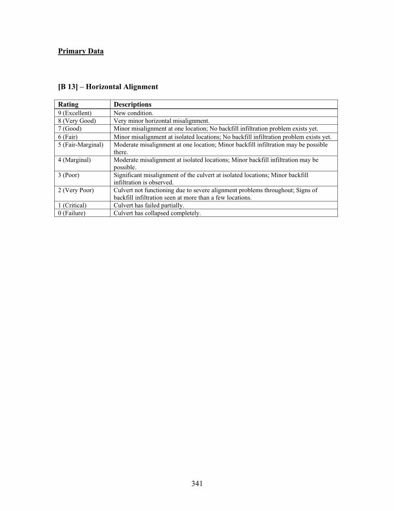
341
Primary Data
[B 13] – Horizontal Alignment
Rating Descriptions 9 (Excellent) New condition. 8 (Very Good) Very minor horizontal misalignment. 7 (Good) Minor misalignment at one location; No backfill infiltration problem exists yet. 6 (Fair) Minor misalignment at isolated locations; No backfill infiltration problem exists yet. 5 (Fair-Marginal) Moderate misalignment at one location; Minor backfill infiltration may be possible
there.4 (Marginal) Moderate misalignment at isolated locations; Minor backfill infiltration may be
possible. 3 (Poor) Significant misalignment of the culvert at isolated locations; Minor backfill
infiltration is observed. 2 (Very Poor) Culvert not functioning due to severe alignment problems throughout; Signs of
backfill infiltration seen at more than a few locations. 1 (Critical) Culvert has failed partially. 0 (Failure) Culvert has collapsed completely.
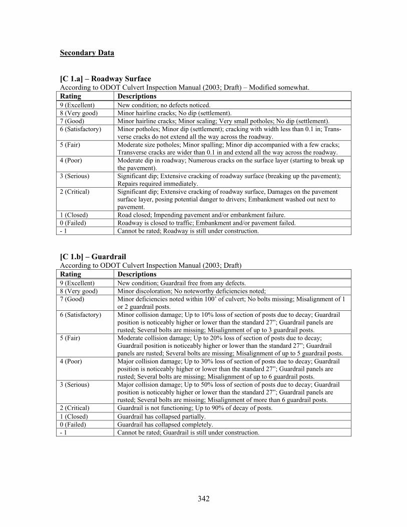
342
Secondary Data
[C 1.a] – Roadway Surface According to ODOT Culvert Inspection Manual (2003; Draft) – Modified somewhat. Rating Descriptions 9 (Excellent) New condition; no defects noticed. 8 (Very good) Minor hairline cracks; No dip (settlement). 7 (Good) Minor hairline cracks; Minor scaling; Very small potholes; No dip (settlement). 6 (Satisfactory) Minor potholes; Minor dip (settlement); cracking with width less than 0.1 in; Trans-
verse cracks do not extend all the way across the roadway. 5 (Fair) Moderate size potholes; Minor spalling; Minor dip accompanied with a few cracks;
Transverse cracks are wider than 0.1 in and extend all the way across the roadway. 4 (Poor) Moderate dip in roadway; Numerous cracks on the surface layer (starting to break up
the pavement). 3 (Serious) Significant dip; Extensive cracking of roadway surface (breaking up the pavement);
Repairs required immediately. 2 (Critical) Significant dip; Extensive cracking of roadway surface, Damages on the pavement
surface layer, posing potential danger to drivers; Embankment washed out next to pavement.
1 (Closed) Road closed; Impending pavement and/or embankment failure. 0 (Failed) Roadway is closed to traffic; Embankment and/or pavement failed. - 1 Cannot be rated; Roadway is still under construction.
[C 1.b] – Guardrail According to ODOT Culvert Inspection Manual (2003; Draft) Rating Descriptions 9 (Excellent) New condition; Guardrail free from any defects. 8 (Very good) Minor discoloration; No noteworthy deficiencies noted; 7 (Good) Minor deficiencies noted within 100’ of culvert; No bolts missing; Misalignment of 1
or 2 guardrail posts. 6 (Satisfactory) Minor collision damage; Up to 10% loss of section of posts due to decay; Guardrail
position is noticeably higher or lower than the standard 27”; Guardrail panels are rusted; Several bolts are missing; Misalignment of up to 3 guardrail posts.
5 (Fair) Moderate collision damage; Up to 20% loss of section of posts due to decay; Guardrail position is noticeably higher or lower than the standard 27”; Guardrail panels are rusted; Several bolts are missing; Misalignment of up to 5 guardrail posts.
4 (Poor) Major collision damage; Up to 30% loss of section of posts due to decay; Guardrail position is noticeably higher or lower than the standard 27”; Guardrail panels are rusted; Several bolts are missing; Misalignment of up to 6 guardrail posts.
3 (Serious) Major collision damage; Up to 50% loss of section of posts due to decay; Guardrail position is noticeably higher or lower than the standard 27”; Guardrail panels are rusted; Several bolts are missing; Misalignment of more than 6 guardrail posts.
2 (Critical) Guardrail is not functioning; Up to 90% of decay of posts. 1 (Closed) Guardrail has collapsed partially. 0 (Failed) Guardrail has collapsed completely. - 1 Cannot be rated; Guardrail is still under construction.

343
[C 2] – Embankment (Apply to Upstream & Downstream Slopes Separately)
According to ODOT Culvert Inspection Manual (2003; Draft) – Modified slightly. Rating Descriptions 9 (Excellent) No noteworthy conditions detected on embankment slopes within 100’ of culvert. 8 (Very Good) Minor erosion in one area away from the culvert; Vegetation intact. 7 (Good) Minor erosion in isolated areas (bare soil exposed slightly) away from the structure,
No threats to the culvert and headwall. 6 (Satisfactory) Moderate erosion in one area away from the structure; Soils exposed in the area; No
threats to the culvert and headwall. 5 (Fair) Moderate erosion in isolated areas, mostly away from the structure; Soils exposed &
guardrail impacted in the area; Minor erosion behind the headwall; No cracks on the headwall.
4 (Poor) Erosion impacting guardrail performance; Moderate erosion behind the headwall; Slope stability problem found in isolated areas; Minor hairline cracks on the headwall; Slight movement of the headwall.
3 (Serious) Slope stability problem at isolated locations (eroding way the shoulder section of the roadway); Severe erosion behind the headwall; It has caused extensive hairline cracks and/or a moderate movement (ex. tilting) on the headwall.
2 (Critical) Severe erosion taking place, causing damage to the roadway shoulder section; headwall has physical damages (ex. severe cracks) and tilted significantly.
1 (Imminent Failure)
One lane of traffic is closed due to embankment failure; Several guardrail posts are hanging in the air due to major erosion and/or slope stability problem.
0 (Failed) Embankment has collapsed (can lead to the loss of culvert). - 1 Cannot be rated; Embankment is still under construction.
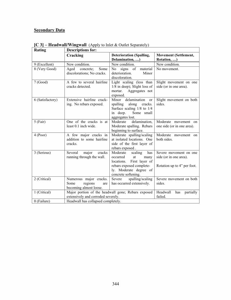
344
Secondary Data
[C 3] – Headwall/Wingwall (Apply to Inlet & Outlet Separately)Descriptions for: RatingCracking Deterioration (Spalling,
Delamination, …) Movement (Settlement, Rotation, …)
9 (Excellent) New condition. New condition. New condition. 8 (Very Good) Aged concrete; Some
discolorations; No cracks. No signs of material deterioration. Minor discoloration.
No movement.
7 (Good) A few to several hairline cracks detected.
Light scaling (less than 1/8 in deep); Slight loss of mortar. Aggregates not exposed.
Slight movement on one side (or in one area).
6 (Satisfactory) Extensive hairline crack-ing. No rebars exposed.
Minor delamination or spalling along cracks. Surface scaling 1/8 to 1/4 in deep. Some small aggregates lost.
Slight movement on both sides.
5 (Fair) One of the cracks is at least 0.1 inch wide.
Moderate delamination, Moderate spalling. Rebars beginning to surface.
Moderate movement on one side (or in one area).
4 (Poor) A few major cracks in addition to some hairline cracks.
Moderate spalling/scaling at isolated locations. One side of the first layer of rebars exposed .
Moderate movement on both sides.
3 (Serious) Several major cracks running through the wall.
Moderate scaling has occurred at many locations. First layer of rebars exposed complete- ly. Moderate degree of concrete softening.
Severe movement on one side (or in one area).
Rotation up to 4” per foot.
2 (Critical) Numerous major cracks. Some regions are becoming almost loose.
Severe spalling/scaling has occurred extensively.
Severe movement on both sides.
1 (Critical) Major portion of the headwall gone; Rebars exposed extensively and corroded severely.
Headwall has partially failed.
0 (Failure) Headwall has collapsed completely.
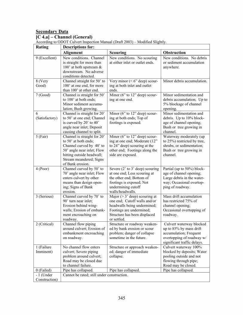
345
Secondary Data[C 4.a] – Channel (General) According to ODOT Culvert Inspection Manual (Draft 2003) – Modified Slightly.
Descriptions for: RatingAlignment Scouring Obstruction
9 (Excellent) New conditions. Channel is straight for more than 100’ at both upstream & downstream. No adverse conditions detected.
New conditions. No scouring at either inlet or outlet ends.
New conditions. No debris or sediment accumulation anywhere.
8 (Very Good)
Channel straight for 50’ to 100’ at one end, for more than 100’ at other end.
Very minor (< 6” deep) scour-ing at both inlet and outlet ends.
Minor debris accumulation.
7 (Good) Channel is straight for 50’ to 100’ at both ends; Minor sediment accumu-lation; Bush growing.
Minor (6” to 12” deep) scour-ing at one end.
Minor sedimentation and debris accumulation; Up to 5% blockage of channel opening.
6(Satisfactory)
Channel is straight for 20’ to 50’ at one end; Channel is curved by 20˚ to 40˚angle near inlet; Deposit causing channel to split.
Minor (6” to 12” deep) scour-ing at both ends; Top of footings is exposed.
Minor sedimentation and debris. Up to 10% block-age of channel opening; Bush or tree growing in channel.
5 (Fair) Channel is straight for 20’ to 50’ at both ends; Channel curved by 40˚ to 50˚ angle near inlet; Flow hitting outside headwall; Stream meandered; Signs of Bank erosion.
Minor (6” to 12” deep) scour-ing at one end; Moderate (12” to 24” deep) scouring at the other end; Footings along the side are exposed.
Waterway moderately (up to 25%) restricted by tree, shrubs, or sedimentation; Bush or tree growing in channel.
4 (Poor) Channel curved by 50˚ to 70˚ angle near inlet; Flow enters culvert by other means than design open-ing; Signs of Bank erosion.
Severe (2’ to 3’ deep) scouring at one end; Less scouring at the other end; Bottom of footings is exposed; Not undermining cutoff walls/headwalls.
Partial (up to 50%) block-age of channel opening; Large debris in the water-way; Occasional overtop-ping of roadway.
3 (Serious) Channel curved by 70˚ to 90˚ turn near inlet; Erosion behind wing-walls; Erosion of embank-ment encroaching on roadway.
Major (> 3’ deep) scouring at one end; Cutoff walls and/or headwalls being undermined; Footings are undermined; Structure has been displaced or settled.
Mass drift accumulation has restricted 75% of channel opening; Occasional overtopping of roadway.
2 (Critical) Channel flow piping around culvert; Erosion of embankment encroaching on roadway.
Structure or roadway weaken-ed by bank erosion or scour problem; danger of collapse sometime in the future.
Culvert waterway blocked up to 85% by mass drift accumulation; Frequent overtopping of roadway w/ significant traffic delays.
1 (Failure Imminent)
No channel flow enters culvert; Severe piping problem around culvert; Road may be closed due to channel failure.
Structure or approach weaken-ed; danger of immediate collapse.
Culvert waterway 100% blocked by deposits; Water pooling outside and not flowing through pipe; Road may be closed.
0 (Failed) Pipe has collapsed. Pipe has collapsed. Pipe has collapsed. - 1 (Under Construction)
Cannot be rated; still under construction.

346
[C 4.b] Channel (Protection)
According to ODOT Culvert Inspection Manual (2003; Draft) Rating Descriptions 9 (Excellent) Channel protections are not required or are in a stable condition. 8 (Very Good) No noteworthy deficiencies that affect the channel protection; Banks are protected or
well vegetated. 7 (Good) Channel bank is beginning to slump; Embankment protection has minor damage;
Bank protection is in need of minor repairs. 6 (Satisfactory) Riprap starting to wash away; Cracked concrete channel protection. 5 (Fair) Broken up concrete channel protection at inlet; Bank protection has eroded. 4 (Poor) Channel protection is severely undermined; Stone is completely washed away; Major
erosion; Failed concrete channel protection; Bank or embankment protection is severely undermined.
3 (Serious) Channel protection has failed; Channel has moved to where the culvert and approach roadway are threatened.
2 (Critical) Channel protection has failed; Channel flow is causing major scour effects. 1 (Imminent Failure)
Culvert closed because of channel failure.
0 (Failed) Culvert has collapsed completely.
[C6] Sediment Inside Culvert
Rating Descriptions 9 (Excellent) New condition; No sediment accumulation at all. 8 (Very Good) Less than 0.5 in. deep sediment accumulation inside the culvert; Sediment has no
impact on drainage flow. 7 (Good) 0.5 to 2 in. deep sediment accumulation inside the culvert; or Up to 5% of the culvert
opening is filled with sediment ; Sediment has little impact on drainage flow. 6 (Satisfactory) 2 to 4 in. deep sediment accumulation inside the culvert; or Up to 10% of the culvert
opening is filled with sediment 5 (Fair) 4 to 6 in. deep sediment accumulation inside the culvert; or Up to 25% of the culvert
opening is filled with sediment 4 (Poor) Sediment accumulation up to 12 in. in some areas inside the culvert; or Up to 35% of
the culvert opening is filled with sediment Sedimentation begins to affect the drainage flow through the culvert.
3 (Serious) Sediment accumulation up to 24 in. in some areas inside the culvert; or Up to 50% of the culvert opening is filled with sediment
2 (Critical) Sediment accumulation up to 36 in. in some areas inside the culvert; or Up to 65% of the culvert opening is filled with sediment
1 (Imminent Failure)
Sediment accumulation is more than 36 in. inside the culvert; Up to 80% of the culvert opening is filled with sediment; Hydraulic function of the original culvert has been severely diminished.
0 (Not Functioning)
The culvert is silted up with sediment all the way. The culvert is not functioning as a drainage structure.
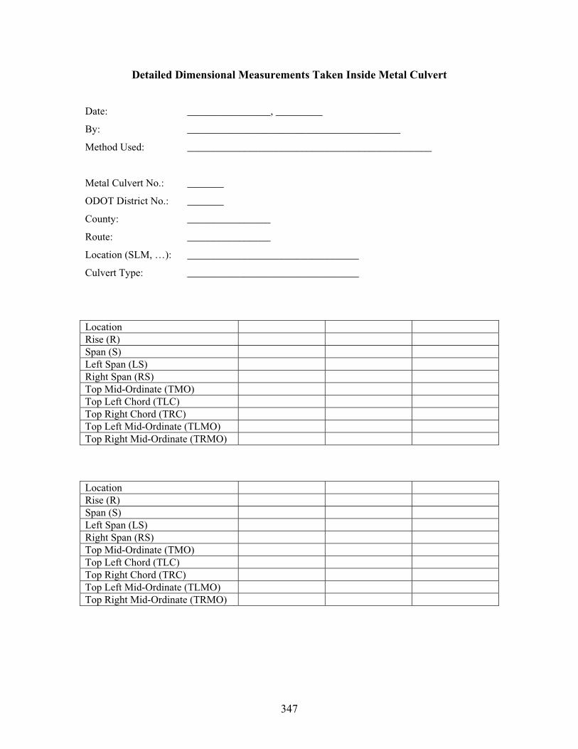
347
Detailed Dimensional Measurements Taken Inside Metal Culvert
Date: ________________, _________
By: _________________________________________
Method Used: _______________________________________________
Metal Culvert No.: _______
ODOT District No.: _______
County: ________________
Route: ________________
Location (SLM, …): _________________________________
Culvert Type: _________________________________
Location Rise (R) Span (S) Left Span (LS) Right Span (RS) Top Mid-Ordinate (TMO) Top Left Chord (TLC) Top Right Chord (TRC) Top Left Mid-Ordinate (TLMO) Top Right Mid-Ordinate (TRMO)
Location Rise (R) Span (S) Left Span (LS) Right Span (RS) Top Mid-Ordinate (TMO) Top Left Chord (TLC) Top Right Chord (TRC) Top Left Mid-Ordinate (TLMO) Top Right Mid-Ordinate (TRMO)
348
APPENDIX D: Proposed Culvert Rating System (Thermoplastic Pipe Culverts)
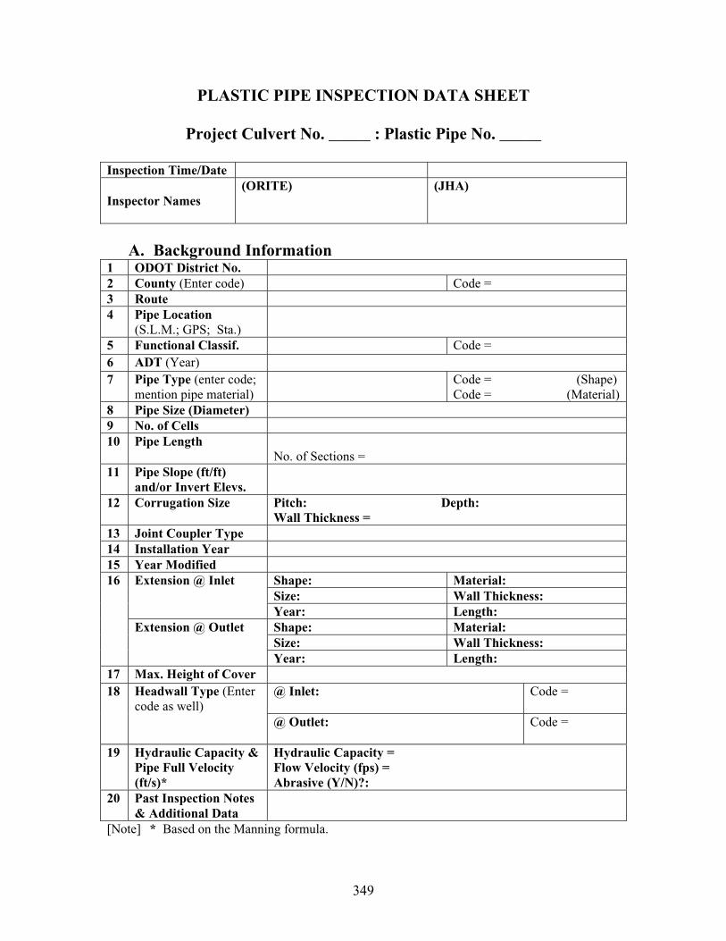
349
PLASTIC PIPE INSPECTION DATA SHEET
Project Culvert No. _____ : Plastic Pipe No. _____
Inspection Time/Date
Inspector Names (ORITE) (JHA)
A. Background Information 1 ODOT District No. 2 County (Enter code) Code = 3 Route4 Pipe Location
(S.L.M.; GPS; Sta.)5 Functional Classif. Code = 6 ADT (Year)7 Pipe Type (enter code;
mention pipe material) Code = (Shape)
Code = (Material) 8 Pipe Size (Diameter) 9 No. of Cells 10 Pipe Length
No. of Sections = 11 Pipe Slope (ft/ft)
and/or Invert Elevs. 12 Corrugation Size Pitch: Depth:
Wall Thickness =13 Joint Coupler Type 14 Installation Year 15 Year Modified
Shape: Material: Size: Wall Thickness:
Extension @ Inlet
Year: Length: Shape: Material: Size: Wall Thickness:
16
Extension @ Outlet
Year: Length: 17 Max. Height of Cover
@ Inlet: Code = 18 Headwall Type (Entercode as well)
@ Outlet: Code =
19 Hydraulic Capacity & Pipe Full Velocity (ft/s)*
Hydraulic Capacity = Flow Velocity (fps) = Abrasive (Y/N)?:
20 Past Inspection Notes & Additional Data
[Note] * Based on the Manning formula.

350
Page 2 - ____ of 6
B. Primary Data Collected @ Station _____________________ Describe below the station location with respect to the plastic pipe structure:
ODOT District No. County Code = RoutePlastic Pipe Description Code = Time/Date of Inspection
1 Rise (Vert. Diameter) Dimension
2 Span (Horiz. Diameter) Dimension
Deflection: 3 Shape Observations (Enter rating & notes for each item) Distortion:
Cracking:4 Pipe Wall Surface in Crown Region (Enter rating & notes for each item)
Buckling:
Cracking: 5 Pipe Wall Surface in Shoulder Region (Enter rating & notes for each item)
Buckling:
Cracking:6 Pipe Wall Surface in Springline Region (Enter rating & notes for each item)
Buckling:
Cracking:7 Pipe Wall Surface in Haunch Region (Enter rating & notes for each item)
Buckling:
Buckling:8 Pipe Wall Surface in Invert Region (Enter rating & notes for each item)
Buckling:
Opening:9 Joints (Enter rating & notes for each item) Cracks:
[Note] Use multiple copies of this page for recording primary inspection data at additional stations established along the plastic pipe structure. Refer to the attached rating criteria for plastic pipes.

351
Page 3 of 6
B. Primary Data Collected – Continued
ODOT District No. County Code = RoutePlastic Pipe Description Code = Time/Date of Inspection
10 Inlet Condition
(Enter rating & notes)
11 Outlet Condition
(Enter rating & notes)
12 Slope & Settlement (including sagging)
(Enter rating & notes) 13 Horiz. Alignment
(Enter rating & notes)
14 Additional Data
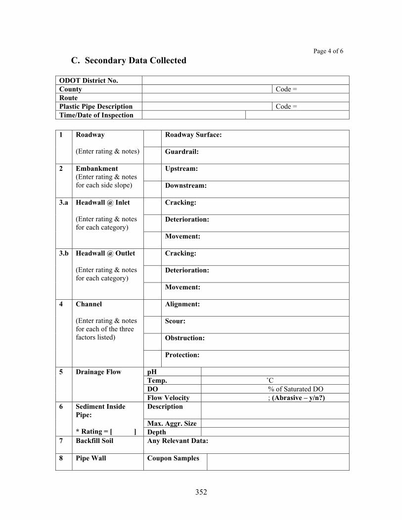
352
Page 4 of 6
C. Secondary Data Collected
ODOT District No. County Code = RoutePlastic Pipe Description Code = Time/Date of Inspection
Roadway Surface: 1 Roadway
(Enter rating & notes) Guardrail:
Upstream: 2 Embankment (Enter rating & notes for each side slope) Downstream:
Cracking:
Deterioration:
3.a Headwall @ Inlet
(Enter rating & notes for each category)
Movement:
Cracking:
Deterioration:
3.b Headwall @ Outlet
(Enter rating & notes for each category)
Movement:
Alignment:
Scour:
Obstruction:
4 Channel
(Enter rating & notes for each of the three factors listed)
Protection:
pH Temp. ˚CDO % of Saturated DO
5 Drainage Flow
Flow Velocity ; (Abrasive – y/n?)Description
Max. Aggr. Size
6 Sediment Inside Pipe:
* Rating = [ ] Depth7 Backfill Soil Any Relevant Data:
8 Pipe Wall Coupon Samples

353
Page 5 of 6
C. Secondary Data Collected
ODOT District No. County Code = RoutePlastic Pipe Description Code = Time/Date of Inspection
9 Additional Data
ex. Wingwalls (if any)
D. Photographs Taken
Type of Camera Used Photographer’s Name No. of Pictures Taken Management of Pictures Taken
E. Level of Inspection
Components Inlet Section Outlet Section Main Barrel Level of Inspection: Specify --- X = Inspection from ends (no entry) M = Manned entry inspection V = Video inspection Type of Video Equipment Used
Additional Comments

354
Page 6 of 6
F. Field Sketches
ODOT District No. County Code = RoutePlastic Pipe Description Code = Time/Date of Inspection
Draw sketches in the space below to describe conditions encountered in the field (if necessary):

355
Dimensional Measurements Taken Inside Plastic Pipe
Date: ___________________, ___________
By: _________________________________________
Plastic Pipe No.: _______
ODOT District No.: _______
County: ________________
Route: ________________
Location (SLM, …): _________________________________
Pipe Type: _________________________________
Method of Measurements: ___________________________________
Item Data:
Location of Cross-Section
Rise or Vertical Diameter (R)
Span or Horizontal Diameter (S)
Additional Measurements or Notes
Item Data:
Location of Cross-Section
Rise or Vertical Diameter (R)
Span or Horizontal Diameter (S)
Additional Measurements or Notes
Item Data:
Location of Cross-Section
Rise or Vertical Diameter (R)
Span or Horizontal Diameter (S)
Additional Measurements or Notes

356
Primary Data
[B 3] – Shape Rating Category Conditions
Deflection Less than 1% over the design value. 9 (Excellent) Distortion Circular, symmetric shape; No flattening, no bulging. Deflection Between 1% and 2% over the design value. 8 (Very Good) Distortion Slightly oval shape, Symmetric; Almost no flattening; No bulging. Deflection Between 2% and 2.5% over the design value. 7 (Good) Distortion Slightly oval shape, Symmetric; Minor flattening; No bulging. Deflection Between 2.5% and 3% over the design value. 6 (Fair) Distortion Oval shape, symmetric; Minor flattening and/or Minor bulging. Deflection Between 3% and 3.5% over the design value. 5 (Fair-Marginal) Distortion Slightly non-symmetric; Moderate flattening and/or Moderate bulging. Deflection Between 3.5% and 4% over the design value. 4 (Marginal) Distortion Moderately non-symmetric; Severe flattening and/or Severe bulging. Deflection Between 4% and 5% over the design value. 3 (Poor) Distortion Significant distortion; Severe flattening and/or Severe bulging.
2 (Very Poor) Deflection More than 5% over the design value; Pipe has not collapsed yet. 1 (Failure) Deflection More than 10% over the design value; Pipe has not collapsed yet. 0 (Failure) Pipe has collapsed completely. [Note] Deflection = Vertical Deflection = (Reduction in Vertical Inside Diameter) divided by (Design Vertical Inside Diameter).
[B 4 through B 8] – Pipe Wall Surface Rating Category Conditions
Cracking No cracking, no discoloration. 9 (Excellent) Buckling Smooth wall, No signs of wall buckling. Cracking No cracking, Minor discoloration at isolated locations. 8 (Very Good) Buckling --- Cracking Minor hairline cracking at one or two isolated locations; No opening at
seams. 7 (Good)
Buckling Relatively smooth wall; Signs of minor wall buckling. Cracking Minor hairline cracking at more than a few isolated locations; No opening
at seams. 6 (Fair)
Buckling Minor dimpling appearing at isolated small area (less than 1/16 of circum-ference or 11.25˚ arc area); Dimples less than 0.25 in. deep.
Cracking Minor hairline cracking at more than a few isolated locations; Minor opening at isolated seams.
5 (Fair- Marginal)
Buckling Minor dimpling appearing over 1/16 to 1/8 of circumference or 11.25˚ to 22.5˚ arc area); Dimples less than 0.25 in. deep.
Cracking Extensive hairline cracking. Minor opening at isolated seams. 4 (Marginal) Buckling Moderate degree of dimpling appearing; Dimples between 0.25 and 0.5
in. deep. Cracking Cracks extensive, some cracks opening greater than 0.1 in.; Opening at
seams. No signs of backfill infiltration and/or exfiltration. 3 (Poor)
Buckling Moderate degree of dimpling appearing; Dimples more than 0.5 in. deep. No wall tearing/cracking yet in the buckled region.
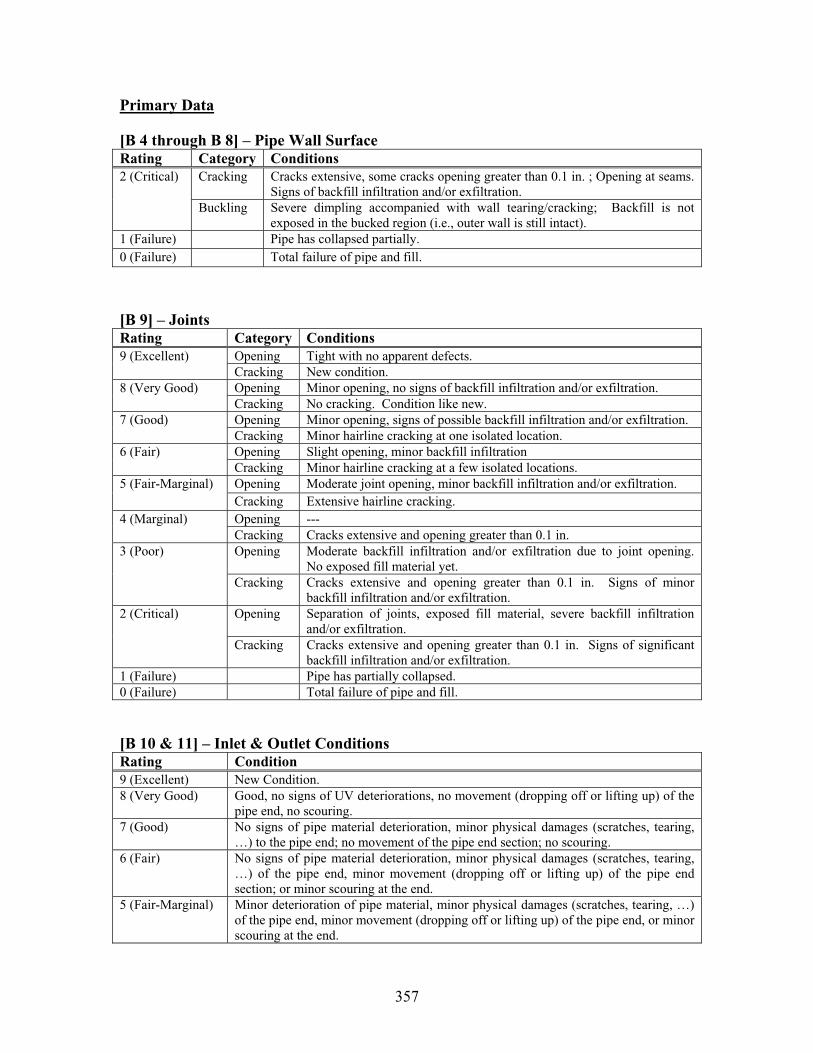
357
Primary Data
[B 4 through B 8] – Pipe Wall Surface Rating Category Conditions
Cracking Cracks extensive, some cracks opening greater than 0.1 in. ; Opening at seams. Signs of backfill infiltration and/or exfiltration.
2 (Critical)
Buckling Severe dimpling accompanied with wall tearing/cracking; Backfill is not exposed in the bucked region (i.e., outer wall is still intact).
1 (Failure) Pipe has collapsed partially. 0 (Failure) Total failure of pipe and fill.
[B 9] – Joints Rating Category Conditions
Opening Tight with no apparent defects. 9 (Excellent) Cracking New condition. Opening Minor opening, no signs of backfill infiltration and/or exfiltration. 8 (Very Good) Cracking No cracking. Condition like new. Opening Minor opening, signs of possible backfill infiltration and/or exfiltration. 7 (Good) Cracking Minor hairline cracking at one isolated location. Opening Slight opening, minor backfill infiltration 6 (Fair) Cracking Minor hairline cracking at a few isolated locations. Opening Moderate joint opening, minor backfill infiltration and/or exfiltration. 5 (Fair-Marginal) Cracking Extensive hairline cracking. Opening --- 4 (Marginal) Cracking Cracks extensive and opening greater than 0.1 in. Opening Moderate backfill infiltration and/or exfiltration due to joint opening.
No exposed fill material yet. 3 (Poor)
Cracking Cracks extensive and opening greater than 0.1 in. Signs of minor backfill infiltration and/or exfiltration.
Opening Separation of joints, exposed fill material, severe backfill infiltration and/or exfiltration.
2 (Critical)
Cracking Cracks extensive and opening greater than 0.1 in. Signs of significant backfill infiltration and/or exfiltration.
1 (Failure) Pipe has partially collapsed. 0 (Failure) Total failure of pipe and fill.
[B 10 & 11] – Inlet & Outlet ConditionsRating Condition 9 (Excellent) New Condition. 8 (Very Good) Good, no signs of UV deteriorations, no movement (dropping off or lifting up) of the
pipe end, no scouring. 7 (Good) No signs of pipe material deterioration, minor physical damages (scratches, tearing,
…) to the pipe end; no movement of the pipe end section; no scouring. 6 (Fair) No signs of pipe material deterioration, minor physical damages (scratches, tearing,
…) of the pipe end, minor movement (dropping off or lifting up) of the pipe end section; or minor scouring at the end.
5 (Fair-Marginal) Minor deterioration of pipe material, minor physical damages (scratches, tearing, …) of the pipe end, minor movement (dropping off or lifting up) of the pipe end, or minor scouring at the end.

358
Rating Criteria for Plastic Pipes (cont’d)
Primary Data
[B 10 & 11] – Inlet & Outlet ConditionsRating Condition 4 (Marginal) Minor UV deterioration of the pipe material, moderate movement of the pipe end, or
moderate scouring. 3 (Poor) N/A 2 (Very Poor) Significant UV degradation of the pipe material, severe physical damages (large
deformations, cracking, tearing, …) to the pipe end section; severe movement of the end, or severe scouring at the end.
1 (Failure) Pipe and fill partially collapsed. 0 (Failure) Total failure of pipe and fill.
[B 12] – Slope & SettlementRating Descriptions 9 (Excellent) Good; uniform slope; no settlement. 8 (Very Good) Minor settlement at one location. 7 (Good) Minor settlement at isolated locations. 6 (Fair) Minor settlement at numerous locations along the culvert. 5 (Fair-Marginal) Moderate settlement at one location. 4 (Marginal) Moderate settlement of the culvert; some ponding of water due to sagging; upstream
end can be seen from the downstream end. 3 (Poor) Severe settlement in one section. 2 (Very Poor) Pipe is not functioning due to sever settlement problem; upstream end cannot be seen
from the downstream end; ponding of water more than 50% of the pipe length. 1 (Critical) Pipe has partially collapsed. 0 (Failure) Pipe has collapsed completely.
[B 13] – Horizontal Alignment Rating Descriptions 9 (Excellent) New condition. 8 (Very Good) Good: no horizontal misalignment. 7 (Good) Generally good; minor misalignment at one location; no backfill infiltration problem
exists yet. 6 (Fair) Generally fair; minor misalignment at isolated locations; no backfill infiltration
problem exists yet. 5 (Fair-Marginal) Moderate misalignment at one location; minor backfill infiltration may be possible
there.4 (Marginal) Moderate misalignment at isolated locations; minor backfill infiltration may be
possible. 3 (Poor) Significant misalignment of the culvert at isolated locations; minor backfill
infiltration is observed. 2 (Very Poor) Pipe is not functioning due to severe alignment problems throughout; signs of
backfill infiltration seen at more than a few locations. 1 (Critical) Pipe has failed partially. 0 (Failure) Pipe has collapsed completely.

359
Rating Criteria for Plastic Pipes (cont’d)
Secondary Data
[C 1.a] – Roadway Surface According to ODOT Culvert Inspection Manual (2003; Draft) – Modified somewhat. Rating Descriptions 9 (Excellent) New condition; no defects noticed. 8 (Very good) Minor hairline cracks; No dip (settlement). 7 (Good) Minor hairline cracks; Minor scaling; Very small potholes; No dip (settlement). 6 (Satisfactory) Minor potholes; Minor dip (settlement); cracking with width less than 0.1 in;
Transverse cracks do not extend all the way across the roadway. 5 (Fair) Moderate size potholes; Minor spalling; Minor dip accompanied with a few cracks;
Transverse cracks are wider than 0.1 in and extend all the way across the roadway. 4 (Poor) Moderate dip in roadway; Numerous cracks on the surface layer (starting to break up
the pavement). 3 (Serious) Significant dip; extensive cracking of roadway surface (breaking up the pavement);
Repairs required immediately. 2 (Critical) Significant dip; extensive cracking of roadway surface, damages on the pavement
surface layer, posing potential danger to drivers; Embankment washed out next to pavement.
1 (Closed) Road closed; Impending pavement and/or embankment failure. 0 (Failed) Roadway is closed to traffic; Embankment and/or pavement failed. - 1 Cannot be rated; Roadway is still under construction.
[C 1.b] – Guardrail According to ODOT Culvert Inspection Manual (2003; Draft) Rating Descriptions 9 (Excellent) New condition; Guardrail free from any defects. 8 (Very good) Minor discoloration; No noteworthy deficiencies noted; 7 (Good) Minor deficiencies noted within 100’ of culvert; No bolts missing; Misalignment of 1
or 2 guardrail posts. 6 (Satisfactory) Minor collision damage; Up to 10% loss of section of posts due to decay; Guardrail
position is noticeably higher or lower than the standard 27”; Guardrail panels are rusted; Several bolts are missing; Misalignment of up to 3 guardrail posts.
5 (Fair) Moderate collision damage; Up to 20% loss of section of posts due to decay; Guardrail position is noticeably higher or lower than the standard 27”; Guardrail panels are rusted; Several bolts are missing; Misalignment of up to 5 guardrail posts.
4 (Poor) Major collision damage; Up to 30% loss of section of posts due to decay; Guardrail position is noticeably higher or lower than the standard 27”; Guardrail panels are rusted; Several bolts are missing; Misalignment of up to 6 guardrail posts.
3 (Serious) Major collision damage; Up to 50% loss of section of posts due to decay; Guardrail position is noticeably higher or lower than the standard 27”; Guardrail panels are rusted; Several bolts are missing; Misalignment of more than 6 guardrail posts.
2 (Critical) Guardrail is not functioning; Up to 90% of decay of posts. 1 (Closed) Guardrail has collapsed partially. 0 (Failed) Guardrail has collapsed completely. - 1 Cannot be rated; Guardrail is still under construction.
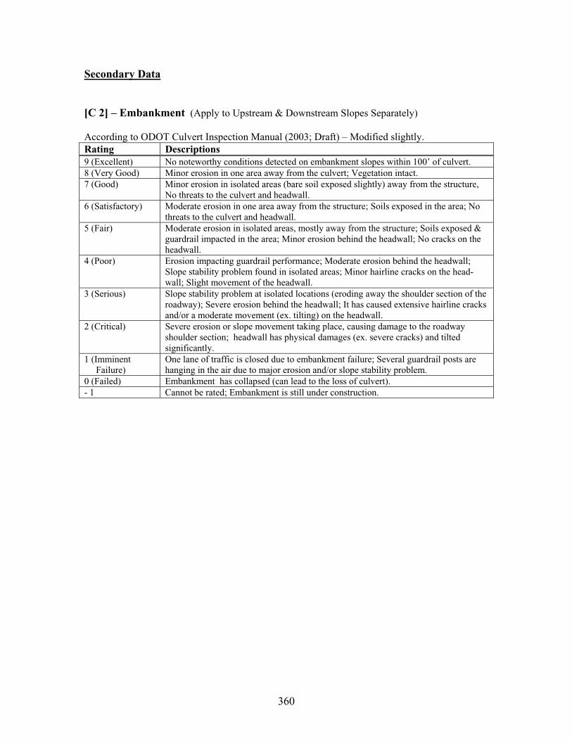
360
Secondary Data
[C 2] – Embankment (Apply to Upstream & Downstream Slopes Separately)
According to ODOT Culvert Inspection Manual (2003; Draft) – Modified slightly. Rating Descriptions 9 (Excellent) No noteworthy conditions detected on embankment slopes within 100’ of culvert. 8 (Very Good) Minor erosion in one area away from the culvert; Vegetation intact. 7 (Good) Minor erosion in isolated areas (bare soil exposed slightly) away from the structure,
No threats to the culvert and headwall. 6 (Satisfactory) Moderate erosion in one area away from the structure; Soils exposed in the area; No
threats to the culvert and headwall. 5 (Fair) Moderate erosion in isolated areas, mostly away from the structure; Soils exposed &
guardrail impacted in the area; Minor erosion behind the headwall; No cracks on the headwall.
4 (Poor) Erosion impacting guardrail performance; Moderate erosion behind the headwall; Slope stability problem found in isolated areas; Minor hairline cracks on the head-wall; Slight movement of the headwall.
3 (Serious) Slope stability problem at isolated locations (eroding away the shoulder section of the roadway); Severe erosion behind the headwall; It has caused extensive hairline cracks and/or a moderate movement (ex. tilting) on the headwall.
2 (Critical) Severe erosion or slope movement taking place, causing damage to the roadway shoulder section; headwall has physical damages (ex. severe cracks) and tilted significantly.
1 (Imminent Failure)
One lane of traffic is closed due to embankment failure; Several guardrail posts are hanging in the air due to major erosion and/or slope stability problem.
0 (Failed) Embankment has collapsed (can lead to the loss of culvert). - 1 Cannot be rated; Embankment is still under construction.

361
Secondary Data
[C 3] – Headwall/Wingwall (Apply to Inlet & Outlet Separately)Descriptions for: RatingCracking Deterioration (Spalling,
Delamination, …) Movement (Settlement, Rotation, …)
9 (Excellent) New condition. New condition. New condition. 8 (Very Good) Concrete aged, some
discolorations, No cracks. No signs of material deterioration. Minor discoloration.
No movement.
7 (Good) A few to several hairline cracks detected.
Light scaling (less than 1/8 in deep); Slight loss of mortar. Aggregates not exposed.
Slight movement on one side (or in one area).
6 (Satisfactory) Extensive hairline crack-ing. No rebars exposed.
Minor delamination or spalling along cracks. Surface scaling 1/8 to 1/4 in deep. Some small aggregates lost.
Slight movement on both sides.
5 (Fair) One of the cracks is at least 0.1 inch wide.
Moderate delamination, Moderate spalling. Rebars beginning to surface.
Moderate movement on one side (or in one area).
4 (Poor) A few major cracks in addition to some hairline cracks.
Moderate spalling/scaling at isolated locations. One side of the first layer of rebars exposed .
Moderate movement on both sides.
3 (Serious) Several major cracks running through the wall.
Moderate scaling has occurred at many locations. First layer of rebars exposed complete- ly. Moderate degree of concrete softening.
Severe movement on one side (or in one area).
Rotation up to 4” per foot.
2 (Critical) Numerous major cracks. Some regions are becoming almost loose.
Severe spalling/scaling has occurred extensively.
Severe movement on both sides.
1 (Critical) Major portion of the headwall gone; Rebars exposed extensively and corroded severely.
Headwall has partially failed.
0 (Failure) Headwall has collapsed completely.

362
Secondary Data[C 4.a] – Channel (General) According to ODOT Culvert Inspection Manual (Draft 2003) – Modified Slightly.
Descriptions for: RatingAlignment Scouring Obstruction
9 (Excellent) New conditions. Channel is straight for more than 100’ at both upstream & downstream. No adverse conditions detected.
New conditions. No scouring at either inlet or outlet ends.
New conditions. No debris or sediment accumulation anywhere.
8 (Very Good)
Channel straight for 50’ to 100’ at one end, for more than 100’ at other end.
Very minor (< 6” deep) scour-ing at both inlet and outlet ends.
Minor debris accumulation.
7 (Good) Channel is straight for 50’ to 100’ at both ends; Minor sediment accumu-lation; Bush growing.
Minor (6” to 12” deep) scour-ing at one end.
Minor sedimentation and debris accumulation; Up to 5% blockage of channel opening.
6(Satisfactory)
Channel is straight for 20’ to 50’ at one end; Channel is curved by 20˚ to 40˚angle near inlet; Deposit causing channel to split.
Minor (6” to 12” deep) scour-ing at both ends; Top of footings is exposed.
Minor sedimentation and debris. Up to 10% block-age of channel opening; Bush or tree growing in channel.
5 (Fair) Channel is straight for 20’ to 50’ at both ends; Channel curved by 40˚ to 50˚ angle near inlet; Flow hitting outside headwall; Stream meandered; Signs of Bank erosion.
Minor (6” to 12” deep) scour-ing at one end; Moderate (12” to 24” deep) scouring at the other end; Footings along the side are exposed.
Waterway moderately (up to 25%) restricted by tree, shrubs, or sedimentation; Bush or tree growing in channel.
4 (Poor) Channel curved by 50˚ to 70˚ angle near inlet; Flow enters culvert by other means than design open-ing; Signs of Bank erosion.
Severe (2’ to 3’ deep) scouring at one end; Less scouring at the other end; Bottom of footings is exposed; Not undermining cutoff walls/headwalls.
Partial (up to 50%) block-age of channel opening; Large debris in the water-way; Occasional overtop-ping of roadway.
3 (Serious) Channel curved by 70˚ to 90˚ turn near inlet; Erosion behind wing-walls; Erosion of embank-ment encroaching on roadway.
Major (> 3’ deep) scouring at one end; Cutoff walls and/or headwalls being undermined; Footings are undermined; Structure has been displaced or settled.
Mass drift accumulation has restricted 75% of channel opening; Occasional overtopping of roadway.
2 (Critical) Channel flow piping around culvert; Erosion of embankment encroaching on roadway.
Structure or roadway weaken-ed by bank erosion or scour problem; danger of collapse sometime in the future.
Culvert waterway blocked up to 85% by mass drift accumulation; Frequent overtopping of roadway w/ significant traffic delays.
1 (Failure Imminent)
No channel flow enters culvert; Severe piping problem around culvert; Road may be closed due to channel failure.
Structure or approach weaken-ed; danger of immediate collapse.
Culvert waterway 100% blocked by deposits; Water pooling outside and not flowing through pipe; Road may be closed.
0 (Failed) Pipe has collapsed. Pipe has collapsed. Pipe has collapsed. - 1 (Under Construction)
Cannot be rated; still under construction.

363
[C 4.b] Channel (Protection) According to ODOT Culvert Inspection Manual (2003; Draft) Rating Descriptions 9 (Excellent) Channel protections are not required or are in a stable condition. 8 (Very Good) No noteworthy deficiencies that affect the channel protection; Banks are protected or
well vegetated. 7 (Good) Channel bank is beginning to slump; Embankment protection has minor damage;
Bank protection is in need of minor repairs. 6 (Satisfactory) Riprap starting to wash away; Cracked concrete channel protection. 5 (Fair) Broken up concrete channel protection; Bank protection is eroded. 4 (Poor) Channel protection is severely undermined; Stone is completely washed away; Major
erosion; Failed concrete channel protection at inlet; Bank or embankment protection is severely undermined.
3 (Serious) Channel protection has failed; Channel has moved to where the culvert and approach roadway are threatened.
2 (Critical) Channel protection has failed; Channel flow is causing major scour effects. 1 (Imminent Failure)
Culvert closed because of channel failure.
0 (Failed) Culvert has collapsed completely.
[C6] Sediment Inside Culvert
Rating Descriptions 9 (Excellent) New condition; No sediment accumulation at all. 8 (Very Good) Less than 0.5 in. deep sediment accumulation inside the culvert; Sediment has no
impact on drainage flow. 7 (Good) 0.5 to 2 in. deep sediment accumulation inside the culvert; or Up to 5% of the culvert
opening is filled with sediment ; Sediment has little impact on drainage flow. 6 (Satisfactory) 2 to 4 in. deep sediment accumulation inside the culvert; or Up to 10% of the culvert
opening is filled with sediment 5 (Fair) 4 to 6 in. deep sediment accumulation inside the culvert; or Up to 25% of the culvert
opening is filled with sediment 4 (Poor) Sediment accumulation up to 12 in. in some areas inside the culvert; or Up to 35% of
the culvert opening is filled with sediment Sedimentation begins to affect the drainage flow through the culvert.
3 (Serious) Sediment accumulation up to 24 in. in some areas inside the culvert; or Up to 50% of the culvert opening is filled with sediment
2 (Critical) Sediment accumulation up to 36 in. in some areas inside the culvert; or Up to 65% of the culvert opening is filled with sediment
1 (Imminent Failure)
Sediment accumulation is more than 36 in. inside the culvert; Up to 80% of the culvert opening is filled with sediment; Hydraulic function of the original culvert has been severely diminished.
0 (Not Functioning)
The culvert is silted up with sediment all the way. The culvert is not functioning as a drainage structure.

364
APPENDIX E: Culvert Spreadsheet Data (on CD-ROM Disk)
APPENDIX F: Culvert Photographs (on CD-ROM Disk)

365
APPENDIX G: Culvert Rehabilitation Techniques
Engineering Drawings and Specifications
366
Specifications were written based on review of manufacture and other government agency specifications along with data collected on the individual treatments. Likewise, sample plan sheets are a compilation of information from similar sources.
Invert ReplacementConsiderations when using ODOT Specification 603.11: ODOT currently has a specification that addresses field paving of a new or existing pipe. (CMS 603.11). This specification is best suited for inverts in good condition or new installations. Deteriorated inverts will require additional reinforcing. Reinforcing for deteriorated inverts should be designed to reintroduce structural integrity to the pipe. Other concerns should be addressed in notes or plan details. For example, the pipe should be cleaned prior to paving. This should include a definition of clean, such as this excerpt from Maryland’s Category 400 Structures specification, “The surface of the structure should be free of all loose scale, concrete, or rust; oil, asphalt coatings, and any other foreign material that would prohibit grout from bonding to the surface of the structure. When placing the grout, the surface should be clean and dry.”
Designer Notes: ODOT’s L&D Manual, Volume 2 requires concrete field paving on certain gauge metal structures for specified design life. District 11 has included cutoff walls to eliminate undermining of the field paving at the inlet end. They report better success using this technique. The plans should either reference the standard reinforcing outlined in the current specification or include a detail depicting the reinforcing mat.
Sample Plan Sheets: On the sample detail sheet, Detail ‘A’, is a good example to include in invert replacement projects. It is from District 11. Detail ‘B’ shows another variation that has been used by the state of Maryland. Detail ‘B’ also includes a proposed detail to be used with circular pipes. A sample plan sheet from District 11, with their cutoff wall is included.
SlipliningProposed Changes to ODOT Supplemental Specification 837: ODOT currently has a draft Supplemental Specification 837, Liner Pipe. It is a comprehensive specification, but ODOT may want to consider modifying the specification or including in plan notes the following:
Add joints shall not decrease the hydraulic capacity of the liner. Clarify size selection based on material selection, since only one liner is shownin the plans, but the contractor can select other ‘equal’ hydraulic choices.Consider requiring ports for insuring complete backfill in larger or longer pipes. These can also act as pressure relief valves during the grouting process. Establish how to determine if all voids are filled. Will sounding the sides of the pipe, or using drill holes to test for voids do this? Require measurement of slope of pipe in sensitive slope conditions. Make reference in SS 837 to the appropriate specification for flowable grout and low strength mortar backfill.

367
Clearer definition of cleaning the pipe. Specify how to determine the pipe is clean.Specify what is to be done if voids are encountered during the cleaning process.This is probably best handled as a plan note with contingency quantities. Require that the contractor verify ability to install the proposed liner prior to ordering pipe. This will eliminate the possibility of ODOT having to buy a pipe that was ordered based on the design survey data. The pipe may have changed shape from the time between the design survey and the contract sold date. Consider establishing guidelines for how far the liner can/cannot protrude from the end of pipe, or how the liner is to be cut. May want to include dewatering basin requirements.
Designer Notes: Designers need to be aware that ODOT generally only shows one option on the plans, but other pipe materials are allowed. For instance, different pipe materials that are allowed may require different pipe sizes for hydraulic reasons. It may be helpful to include a table or listing in the plans of different sizes for different materials if appropriate. Designers should be aware of possible needs to include other pay items in a liner project, such as additional mortar, headwalls, riprap, rock channel protection, and seeding/mulching. If the designer is aware that the pipe is heavily silted or has other extreme conditions, such as dam control, or unusual flow patterns, they should include that information in the general notes, or reference an appropriate contact. Designers should be aware that different pipe material choices will create different velocities and the most extreme should be accounted for in designing the dissipaters, or eliminate that pipe material choice from the options if it is not an appropriate option.
Sample Plan Sheets: The sample plan sheet shown is from District 5 and was observed under construction. District 5 has been doing slipliners for several years. In addition, on the sample details sheet, Detail ‘C’, is a good example of how to indicate placement of grout and lift tubes in the concrete bulkhead.
CIPP (Cured in Place Pipe)Proposed Draft Specification: One significant change to the current specifications used by ODOT is to not include the filling of voids as incidental to the CIPP. Designing the liner, cleaning the pipe and inspection is still incidental to the cost of the CIPP. The recommended draft specification is shown below.
Designer Notes: Designer should make sure there is enough space for setting up necessary equipment and still maintain traffic in an acceptable manner. Also, the designer needs to consider if facilities are available to dispose of hot water that could contain styrene. Design should be based on fully deteriorated gravity pipe as per ASTM F-1216. Any filling of voids should be paid under a separate pay item.

368
Sample Plan Sheet: The included sample plan sheet is from a project in District 11.
369
STATE OF OHIO DEPARTMENT OF TRANSPORTATION
SUPPLEMENTAL SPECIFICATION 999 CURED IN PLACE PIPE
Date
999.01 Description 999.02 Materials999.03 Construction Methods, general 999.04 Delivery and Storage 999.05 Site Preparation 999.06 Installation 999.07 Appearance and Acceptance 999.08 Environmental Requirements 999.09 Method of Measurement 999.10 Basis of Payment
999.01 Description. This work consists of relining an existing culvert structure with a resin impregnated felt tube liner of the type and size specified.
999.02 Materials. Materials supplied shall be accordance with the following specifications: ASTM D-5813, ASTM F-1216, ASTM F-1743. The liner shall be designed by the manufacture as relining a fully deteriorated gravity pipe. The supplier must be from the acceptable list of approved manufacturers, which can be obtained from the Office of Structural Engineering. The liner must provide a flow capacity equal to or greater than that of the host pipe prior to installation.
999.03 Construction Methods, General. Installation shall be per the manufacturer’s recommendations, with special attention to the following details. The contractor shall provide a copy of the manufacturers installation recommendations to the engineer at the pre-construction meeting.
999.04 Delivery and Storage. If the resin is applied off site the resin-impregnated liner shall be kept in thermostatically controlled refrigeration. The liner should not be kept longer than 10 days in refrigeration without the approval of the engineer.
999.05 Site Preparation. The contractor is responsible for cleaning the host pipe prior to liner installation. This includes roots, rocks, silt buildup, and any loose damaged sections of pipe. The engineer must approve the cleaning prior to liner installation.
999.06 Installation. The installation of the liner should be as per the manufacturer’s instructions. Care must be taken that the pipe lining remains free of dirt and debris prior to lining. Temperature during curing must be measured, both inside
370
and outside the tube, to verify temperatures to assure conformance to the cure profile. The CIPP may be installed either using the inversion process as per ASTM F-1216, or the pulled in place method as per ASTM F-1743. The liner used must be designed for the type of installation used. Following the curing process, the heated water must be cooled and disposed of properly. Following the liner completion, the site must be returned to an acceptable condition as per Section 104.
999.07 Appearance and Acceptance. The acceptance of the installed CIPP is based upon an arms reach or CCTV visual inspection. If CCTV is required the contractor shall supply the equipment at the request of the engineer. The CIPP may reflect minor defects at joints or deteriorated areas in the host pipe. Minor wrinkles at bends and joints are acceptable. There should be no holes, splitting, or rupturing in the CIPP. There should be no wrinkles in straight pipe segments. The CIPP should be fully inflated and in tight contact with the host pipe.
999.08 Environmental Requirements. Prior to starting construction, the contractor shall supply to the engineer a plan describing how the hot and possibly styrene-contaminated water will be captured. The plan shall also include the location to be used for disposal.
999.09 Method of Measurement. The quantity shall be for the actual length after the ends are cut. Measurement shall be to the nearest foot (meter).
999.10 Basis of Payment. Payment shall be for completed and accepted quantities at the contract price as follows:
Item Unit Description 999 Foot Conduit, Cured in Place Pipe, ______”, _________(shape) 999 Meter Conduit, Cured in Place Pipe, ______mm, _______(shape)
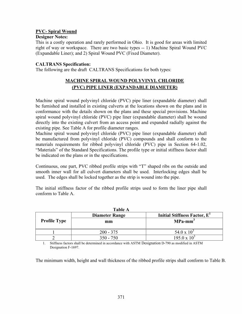
371
PVC- Spiral WoundDesigner Notes: This is a costly operation and rarely performed in Ohio. It is good for areas with limited right of way or workspace. There are two basic types -- 1) Machine Spiral Wound PVC (Expandable Liner); and 2) Spiral Wound PVC (Fixed Diameter).
CALTRANS Specification: The following are the draft CALTRANS Specifications for both types:
MACHINE SPIRAL WOUND POLYVINYL CHLORIDE(PVC) PIPE LINER (EXPANDABLE DIAMETER)
Machine spiral wound polyvinyl chloride (PVC) pipe liner (expandable diameter) shall be furnished and installed in existing culverts at the locations shown on the plans and in conformance with the details shown on the plans and these special provisions. Machine spiral wound polyvinyl chloride (PVC) pipe liner (expandable diameter) shall be wound directly into the existing culvert from an access point and expanded radially against the existing pipe. See Table A for profile diameter ranges. Machine spiral wound polyvinyl chloride (PVC) pipe liner (expandable diameter) shall be manufactured from polyvinyl chloride (PVC) compounds and shall conform to the materials requirements for ribbed polyvinyl chloride (PVC) pipe in Section 64-1.02, “Materials” of the Standard Specifications. The profile type or initial stiffness factor shall be indicated on the plans or in the specifications.
Continuous, one part, PVC ribbed profile strips with “T” shaped ribs on the outside and smooth inner wall for all culvert diameters shall be used. Interlocking edges shall be used. The edges shall be locked together as the strip is wound into the pipe.
The initial stiffness factor of the ribbed profile strips used to form the liner pipe shall conform to Table A.
Table A Diameter Range Initial Stiffness Factor, E1
Profile Type mm MPa-mm3
1 200 - 375 54.0 x 10³
2 350 - 750 195.0 x 10³
1. Stiffness factors shall be determined in accordance with ASTM Designation D-790 as modified in ASTM Designation F-1697.
The minimum width, height and wall thickness of the ribbed profile strips shall conform to Table B.
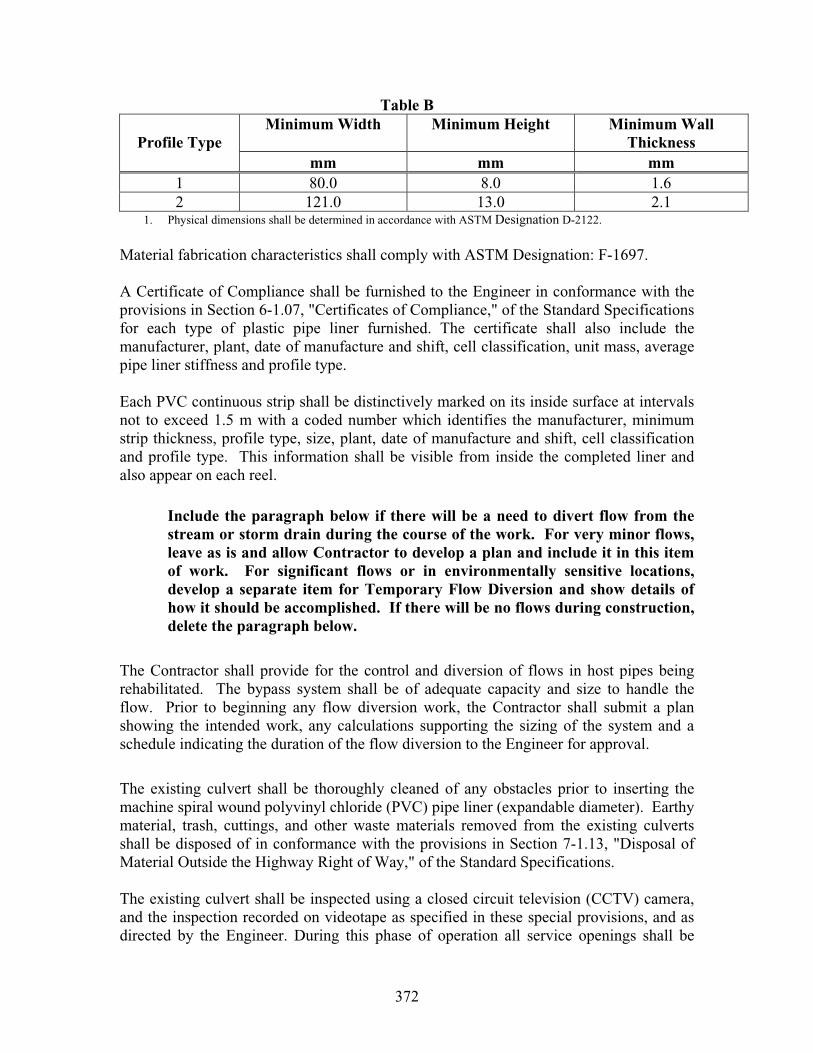
372
Table B Minimum Width Minimum Height Minimum Wall
ThicknessProfile Type mm mm mm
1 80.0 8.0 1.6 2 121.0 13.0 2.1
1. Physical dimensions shall be determined in accordance with ASTM Designation D-2122.
Material fabrication characteristics shall comply with ASTM Designation: F-1697.
A Certificate of Compliance shall be furnished to the Engineer in conformance with the provisions in Section 6-1.07, "Certificates of Compliance," of the Standard Specifications for each type of plastic pipe liner furnished. The certificate shall also include the manufacturer, plant, date of manufacture and shift, cell classification, unit mass, average pipe liner stiffness and profile type.
Each PVC continuous strip shall be distinctively marked on its inside surface at intervals not to exceed 1.5 m with a coded number which identifies the manufacturer, minimum strip thickness, profile type, size, plant, date of manufacture and shift, cell classification and profile type. This information shall be visible from inside the completed liner and also appear on each reel.
Include the paragraph below if there will be a need to divert flow from the stream or storm drain during the course of the work. For very minor flows, leave as is and allow Contractor to develop a plan and include it in this item of work. For significant flows or in environmentally sensitive locations, develop a separate item for Temporary Flow Diversion and show details of how it should be accomplished. If there will be no flows during construction, delete the paragraph below.
The Contractor shall provide for the control and diversion of flows in host pipes being rehabilitated. The bypass system shall be of adequate capacity and size to handle the flow. Prior to beginning any flow diversion work, the Contractor shall submit a plan showing the intended work, any calculations supporting the sizing of the system and a schedule indicating the duration of the flow diversion to the Engineer for approval.
The existing culvert shall be thoroughly cleaned of any obstacles prior to inserting the machine spiral wound polyvinyl chloride (PVC) pipe liner (expandable diameter). Earthy material, trash, cuttings, and other waste materials removed from the existing culverts shall be disposed of in conformance with the provisions in Section 7-1.13, "Disposal of Material Outside the Highway Right of Way," of the Standard Specifications.
The existing culvert shall be inspected using a closed circuit television (CCTV) camera, and the inspection recorded on videotape as specified in these special provisions, and as directed by the Engineer. During this phase of operation all service openings shall be

373
precisely located longitudinally and radially, and logged for subsequent reconnection after the insertion of the liner pipe.
Prior to beginning any pipe lining work, cleaning and inspecting all existing pipe shall be performed as specified elsewhere in these special provisions.
After inspection of the existing pipe, the Contractor shall develop a written proposal describing the planned operations to repair the pipe. At a minimum, the proposal shall describe conditions found that may prevent proper installation of pipe liner (such as any sharp or protruding appurtenances), and methods proposed by the Contractor for correction of the conditions and lateral pipe re-establishment. In addition, the proposal shall describe perforations of existing culvert to be lined, their extent, and methods proposed for correction by the Contractor, including necessary grouting and backfilling. The proposal shall describe the Contractor's proposed procedures and schedules for installing the pipe liner and shall accompany the VHS format inspection recording required above.
For minor patching of small perforations, leave the paragraph below as is and full comp work into this item.
Perforations or spalls in the pipe wall shall be patched with cement mortar conforming to the requirements of Section 65-1.06 of the Standard Specifications. The mortar shall be allowed to dry prior to beginning placement of the spiral-wound PVC liner (expandable diameter).
The Contractor shall obtain the approval of the Engineer prior to beginning any repair work. Any work necessary, as determined by the Engineer, to repair the host prior toinstallation of the machine spiral-wound polyvinyl chloride (PVC) liner (expandable diameter) will be measured and paid for as extra work as provided in Section 4-1.03D of the Standard Specifications unless addressed elsewhere in these special provisions.
Installation of the machine spiral-wound polyvinyl chloride (PVC) liner (expandable diameter) shall be in accordance with ASTM Designation F-1741 using expandable profile liner pressed against existing pipe wall. The machine spiral wound pipe polyvinyl chloride (PVC) liner (expandable diameter) shall be wound directly into the existing culvert from an access point and expanded radially against the existing pipe after insertion. End seals, between the liner pipes and the existing pipe, shall be installed using Cement Mortar in conformance with the provisions in Section 65-1.06, "Joints," of the Standard Specifications.
The Contractor shall perform a CCTV inspection after the installation to establish that the lining has been installed as specified, there are no constrictions or deformities, and all live connections have been reinstated. The CCTV inspection of the lining will be performed in both directions (from each end of the culvert) to verify proper installation. A videotape of the CCTV inspection of the lining shall be made and shall be provided to the Engineer. The Engineer shall be allowed 10 working days to review the videotapes

374
for both pre and post liner installation video inspections prior to approval of the work. If correction work is required to meet the installation recommendations of the manufacturer or to reestablish any live junctions, the Contractor shall perform this work at their own expense.
Machine spiral-wound polyvinyl chloride (PVC) liner (expandable diameter) work to be performed under these specifications will be listed in the contract item by size, type, or whatever information is necessary for identification. Quantities of the pipe liner shall be measured by the meter along the slope length of the host pipe as designated on the plans and confirmed by the Engineer. Liner placed in excess shall not be paid for.
Disconnecting of the existing downdrains, designated on the plans or encountered in the field, prior to the installation of the pipe liner may be required at some locations. Full compensation for disconnecting and reconnecting the existing downdrain shall be considered as included in the contract price paid per meter for the various sizes of Machine spiral-wound polyvinyl chloride (PVC) liner (expandable diameter) in the Engineer’s estimate and no additional compensation will be allowed therefore.
The contract price paid per meter for the various sizes of machine spiral wound plastic pipe liners shall include full compensation for furnishing all labor, materials, tools, equipment, and incidentals, and for doing all the work involved in furnishing and installing the machine wound plastic pipe liners (expandable diameter), complete in place, controlling or diverting existing culvert flow, providing samples, cleaning of existing culverts of obstructions, repairing defects (except for removal of obstructions that cannot be removed by conventional equipment and cleaners), re-establishing all existing connections, cutting, removing, and disposing of a portion of host pipes where machine spiral-wound polyvinyl chloride (PVC) liner (expandable diameter) is to be installed and performing two closed circuit television inspections, complete in place, as shown on the plans, as specified in the Standard Specifications and these special provisions, and as directed by the Engineer.
SPIRAL WOUND POLYVINYL CHLORIDE(PVC) PIPE LINER (FIXED DIAMETER)
Spiral wound polyvinyl chloride (PVC) pipe liner (fixed diameter) shall be furnished and installed in existing culverts at the locations shown on the plans and in conformance with the details shown on the plans and these special provisions. Spiral wound polyvinyl chloride (PVC) pipe liner (fixed diameter) shall be wound directly into the existing culvert from an access point by machine (all pipe sizes) or internally by hand (human entry pipe sizes only).
Spiral wound polyvinyl chloride (PVC) pipe liner (fixed diameter) shall have a nominal diameter, thickness, as shown on the plans or as specified in these special provisions.
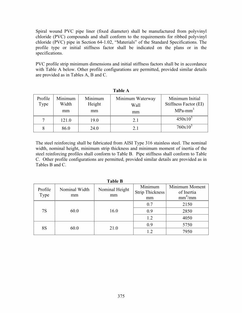
375
Spiral wound PVC pipe liner (fixed diameter) shall be manufactured from polyvinyl chloride (PVC) compounds and shall conform to the requirements for ribbed polyvinyl chloride (PVC) pipe in Section 64-1.02, “Materials” of the Standard Specifications. The profile type or initial stiffness factor shall be indicated on the plans or in the specifications.
PVC profile strip minimum dimensions and initial stiffness factors shall be in accordance with Table A below. Other profile configurations are permitted, provided similar details are provided as in Tables A, B and C.
Table A
Profile Type
Minimum Width mm
Minimum Height
mm
Minimum Waterway Wall mm
Minimum Initial Stiffness Factor (EI)
MPa-mm3
7 121.0 19.0 2.1 450x103
8 86.0 24.0 2.1 760x103
The steel reinforcing shall be fabricated from AISI Type 316 stainless steel. The nominal width, nominal height, minimum strip thickness and minimum moment of inertia of the steel reinforcing profiles shall conform to Table B. Pipe stiffness shall conform to Table C. Other profile configurations are permitted, provided similar details are provided as in Tables B and C.
Table B
Profile Type
Nominal Width mm
Nominal Height mm
Minimum Strip Thickness
mm
Minimum Moment of Inertia mm4/mm
0.7 2150
0.9 2850 7S 60.0 16.0
1.2 4050
0.9 5750 8S 60.0 21.0
1.2 7950

376
Table C
Pipe Stiffness (kPa) for Profile Type: OutsideDiameter
(mm) 7 7S
(0.7 mm)
7S
(0.9 mm)
7S
(1.2 mm)
8 8S
(0.9 mm)
8S
(1.2 mm)
600 50 440
675 50 300 440
750 40 210 310 420
825 30 150 230 310
900 30 120 180 230 60
975 20 90 140 180 50 430
1,050 20 70 110 140 40 350 470
1,125 20 60 90 120 30 290 390
1,200 50 70 100 30 250 330
1,350 30 50 70 20 180 240
1,400 30 40 60 170 220
1,500 20 40 50 140 190
1,600 20 30 40 120 160
1,700 20 30 100 140
1,800 20 30 90 120
1,900 80 100
2,000 70 90
A Certificate of Compliance shall be furnished to the Engineer in conformance with the provisions in Section 6-1.07, "Certificates of Compliance," of the Standard Specifications for each reel of PVC strip furnished. The certificate shall also include the manufacturer, plant, date of manufacture and shift, cell classification, unit mass, average pipe liner stiffness and profile type.
Each PVC continuous strip shall be distinctively marked on its inside surface at intervals not to exceed 1.5m with a coded number which identifies the manufacturer, minimum strip thickness, profile type, size, plant, date of manufacture and shift, cell classification and profile type. This information shall be visible from inside the completed liner and also appear on each reel.
Include the paragraph below if there will be a need to divert flow from the stream or storm drain during the course of the work. For very minor flows, leave as is and allow Contractor to develop a plan and include it in this item
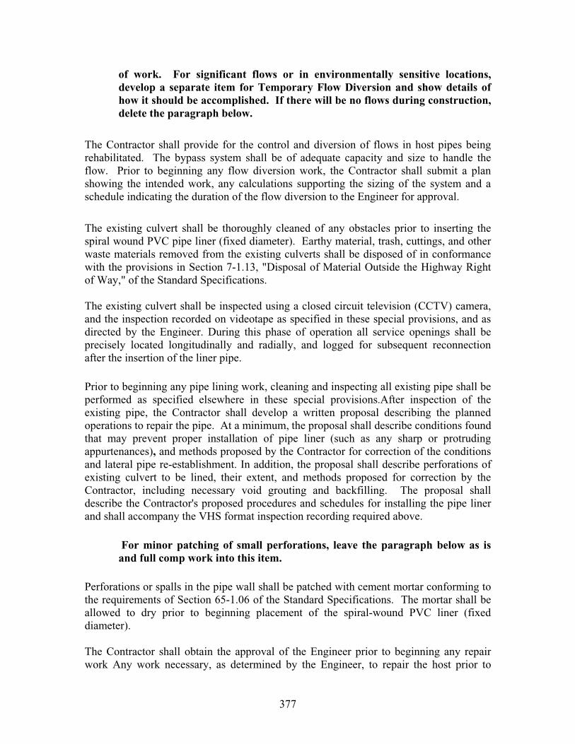
377
of work. For significant flows or in environmentally sensitive locations, develop a separate item for Temporary Flow Diversion and show details of how it should be accomplished. If there will be no flows during construction, delete the paragraph below.
The Contractor shall provide for the control and diversion of flows in host pipes being rehabilitated. The bypass system shall be of adequate capacity and size to handle the flow. Prior to beginning any flow diversion work, the Contractor shall submit a plan showing the intended work, any calculations supporting the sizing of the system and a schedule indicating the duration of the flow diversion to the Engineer for approval.
The existing culvert shall be thoroughly cleaned of any obstacles prior to inserting the spiral wound PVC pipe liner (fixed diameter). Earthy material, trash, cuttings, and other waste materials removed from the existing culverts shall be disposed of in conformance with the provisions in Section 7-1.13, "Disposal of Material Outside the Highway Right of Way," of the Standard Specifications.
The existing culvert shall be inspected using a closed circuit television (CCTV) camera, and the inspection recorded on videotape as specified in these special provisions, and as directed by the Engineer. During this phase of operation all service openings shall be precisely located longitudinally and radially, and logged for subsequent reconnection after the insertion of the liner pipe.
Prior to beginning any pipe lining work, cleaning and inspecting all existing pipe shall be performed as specified elsewhere in these special provisions.After inspection of the existing pipe, the Contractor shall develop a written proposal describing the planned operations to repair the pipe. At a minimum, the proposal shall describe conditions found that may prevent proper installation of pipe liner (such as any sharp or protruding appurtenances), and methods proposed by the Contractor for correction of the conditions and lateral pipe re-establishment. In addition, the proposal shall describe perforations of existing culvert to be lined, their extent, and methods proposed for correction by the Contractor, including necessary void grouting and backfilling. The proposal shall describe the Contractor's proposed procedures and schedules for installing the pipe liner and shall accompany the VHS format inspection recording required above.
For minor patching of small perforations, leave the paragraph below as is and full comp work into this item.
Perforations or spalls in the pipe wall shall be patched with cement mortar conforming to the requirements of Section 65-1.06 of the Standard Specifications. The mortar shall be allowed to dry prior to beginning placement of the spiral-wound PVC liner (fixed diameter).
The Contractor shall obtain the approval of the Engineer prior to beginning any repair work Any work necessary, as determined by the Engineer, to repair the host prior to

378
lining will be measured and paid for as extra work as provided in Section 4-1.03D of the Standard Specifications unless addressed elsewhere in these special provisions.
Installation of the spiral wound PVC pipe liner (fixed diameter) shall be in accordance with ASTM F-1741 using fixed diameter profile and F-1698. A continuous, one part, PVC ribbed liner profile strip with interlocking edges shall be used. Sealants and gaskets necessary for effective interlocking of the edges of PVC strip are pre-applied at the time of manufacture. The edges shall be locked together as the strip is wound into the pipe.
Installation of the spiral wound PVC pipe liner (fixed diameter) shall be in accordance with ASTM F-1741 using fixed diameter profile and F-1698. A continuous, one part, PVC ribbed liner profile strip reinforced with a continuous profiled steel strip with interlocking edges shall be used. Sealants and gaskets necessary for effective interlocking of the edges of PVC strip are pre-applied at the time of manufacture. The edges shall be locked together as the strip is wound into the pipe and the profiled steel band shall be mechanically locked onto the outside of the PVC profile liner pipe.
The spiral wound PVC pipe liner (fixed diameter) shall be wound at a fixed diameter, leaving an annular space between the liner and host pipe wall. The ends of the spiral wound PVC pipe liner (fixed diameter) shall be flush with the host pipe unless a beveled finished product is specified elsewhere in these special provisions.
The Contractor shall perform a CCTV inspection after the installation to establish that the lining has been installed as specified, there are no constrictions or deformities, and all live connections have been reinstated. The CCTV inspection of the lining will be performed in both directions (from each end of the culvert) to verify that the lining has been installed as specified and all live junctions have been reinstated. A video tape of the CCTV inspection of the lining shall be made and shall be provided to the Engineer. The Engineer shall be allowed 10 working days to review the video tapes for both pre and post liner installation video inspections prior to approval of the work. If correction work is required to meet the installation recommendations of the manufacturer or to reestablish any live junctions, the Contractor shall perform this work at their own expense.
The entire annular space between the spiral wound PVC pipe liner (fixed diameter) and the existing culvert shall be filled with grout. The Contactor shall notify the Engineer if the entire annular space between the spiral wound PVC pipe liner (fixed diameter) and the existing culvert cannot be filled with grout prior to starting work.
The grout (low density foam concrete) shall be composed of water, Portland cement, portland cement and fly ash, and/or additives, providing materials are not biodegradable, and a foaming agent is used. The foaming agent shall conform to the requirements in both of ASTM Designations: C-869 and C-796. Portland cement shall conform to the requirements of Section 90-2.01, "Cement," of the Standard Specifications.
The grout shall have a cast density, at the point of placement, of between 850 and 1090 kg/m3 with a minimum penetration resistance of 690 kPa in 24 hours when tested in
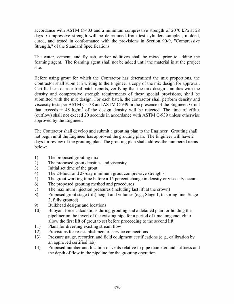
379
accordance with ASTM C-403 and a minimum compressive strength of 2070 kPa at 28 days. Compressive strength will be determined from test cylinders sampled, molded, cured, and tested in conformance with the provisions in Section 90-9, "Compressive Strength," of the Standard Specifications.
The water, cement, and fly ash, and/or additives shall be mixed prior to adding the foaming agent. The foaming agent shall not be added until the material is at the project site.
Before using grout for which the Contractor has determined the mix proportions, the Contractor shall submit in writing to the Engineer a copy of the mix design for approval. Certified test data or trial batch reports, verifying that the mix design complies with the density and compressive strength requirements of these special provisions, shall be submitted with the mix design. For each batch, the contractor shall perform density and viscosity tests per ASTM C-138 and ASTM C-939 in the presence of the Engineer. Grout that exceeds + 48 kg/m3 of the design density will be rejected. The time of efflux (outflow) shall not exceed 20 seconds in accordance with ASTM C-939 unless otherwise approved by the Engineer.
The Contractor shall develop and submit a grouting plan to the Engineer. Grouting shall not begin until the Engineer has approved the grouting plan. The Engineer will have 2 days for review of the grouting plan. The grouting plan shall address the numbered items below:
1) The proposed grouting mix 2) The proposed grout densities and viscosity 3) Initial set time of the grout 4) The 24-hour and 28-day minimum grout compressive strengths 5) The grout working time before a 15 percent change in density or viscosity occurs 6) The proposed grouting method and procedures 7) The maximum injection pressures (including last lift at the crown) 8) Proposed grout stage (lift) height and volumes (e.g., Stage 1, to spring line; Stage
2, fully grouted) 9) Bulkhead designs and locations 10) Buoyant force calculations during grouting and a detailed plan for holding the
pipeliner on the invert of the existing pipe for a period of time long enough to allow the first lift of grout to set before proceeding to the second lift
11) Plans for diverting existing stream flow 12) Provisions for re-establishment of service connections 13) Pressure gauge, recorder, and field equipment certifications (e.g., calibration by
an approved certified lab) 14) Proposed number and location of vents relative to pipe diameter and stiffness and
the depth of flow in the pipeline for the grouting operation
380
15) Strut details 16) Proposed method for monitoring deformation of the pipeliner 17) Written confirmation that the Contractor has coordinated the grouting procedures
with the grout installer and the pipeliner manufacturer.
Data for 1) through 5) shall be derived from trial grout batches as approved by the Engineer.
For each different type of grout or variation in procedure or installation, a complete package shall be submitted. The submittal shall include each of the above items and the locations or conditions to which it applies. The Contractor shall obtain approval from the Engineer for any changes to be made in grout mix, grouting procedure, or installation prior to commencement of grouting operations.
The gauged pumping pressure shall not exceed 35 kPa or manufacturer’s recommendation for spiral wound PVC pipe liners (fixed diameter) with a pipe stiffness of less than 200 kPa and shall not exceed 50 kPa for all other PVC pipe liners (fixed diameter) without steel reinforcement. Grouting pressure shall not exceed 70 kPa for spiral wound steel reinforced PVC pipe liners (fixed diameter). In addition, the PVC pipeliner (fixed diameter) shall be able to withstand a static head of grout of 150 mm above the highest crown elevation. Maximum grout pressure for static grout head shall not exceed maximum allowable gauged pumping pressure for the PVC pipeliner (fixed diameter). The grout shall be placed in a continuous manner and injected in lifts not exceeding the height designated in the grouting plan approved by the Engineer, or less if needed to avoid floating, shifting or deforming the PVC pipeliner (fixed diameter). The injection pressure including the last lift at the crown shall be carefully monitored. If the PVC pipeliner (fixed diameter) cannot withstand the grouting pressures or static head, then the maximum pressure at the point of grout injection must be reduced or staged grouting must be employed, or an alternative pipeliner selected. Deformation the PVC pipeliner (fixed diameter) shall not exceed 5%. The Contractor's placement method shall prevent segregation or voids from occurring in the grout mix.
Prior to grouting, the existing culvert shall be free from water and debris. Grouting shall not begin until the existing stream flow has been temporarily diverted and approved bulkheads installed. Grout injection tubes and breather tubes shall be placed around the liner and through the bulkheads.
As approved by the Engineer, grout injection holes of up to 50 mm in diameter may also be drilled at appropriate points in the spiral wound PVC pipe liner (fixed diameter), plugged with PVC plugs and sealed in place with a bead of approved sealant/adhesive.
Spiral-wound PVC liner (fixed diameter) work to be performed under these specifications will be listed in the contract item by size, type, or whatever information is necessary for identification. Quantities of the pipe liner shall be measured by the meter along the slope length of the host pipe as designated on the plans and confirmed by the Engineer. Spiral-wound polyvinyl chloride PVC liner (fixed diameter) placed in excess shall not be paid
381
for. Upon completion of installing the spiral wound PVC pipe liner (fixed diameter) including annular space grouting, ends of the pipe shall be sealed with cement mortar conforming to the provisions in Section 65-1.06, "Joints," of the Standard Specifications. When beveled ends are shown on the plans, exact dimension in millimeters between end of host pipe and spiral-wound PVC liner (fixed diameter), to be determined by the Engineer prior to sealing ends with cement mortar.
Disconnecting of the existing downdrains, designated on the plans or encountered in the field, prior to the installation of the pipe liner may be required at some locations. Full compensation for disconnecting and reconnecting the existing downdrain shall be considered as included in the contract price paid per meter for the various sizes of spiral-wound polyvinyl chloride (PVC) liner (fixed diameter) in the Engineer’s estimate and no additional compensation will be allowed therefore.
The contract price paid per meter for the different sizes of spiral wound PVC pipe liner (fixed diameter) shall include full compensation for furnishing all labor, materials (including grout), tools, equipment, and incidentals, and for doing all the work involved in installing spiral wound PVC pipe liner (fixed diameter), complete in place, including cleaning of existing culverts of obstructions, re-establishing all existing connections, annular space grouting, providing samples, repairing defects (except for removal of obstructions that cannot be removed by conventional equipment and cleaners), cutting, removing, and disposing of a portion of host pipes where spiral-wound PVC liner (fixed diameter) is to be installed and performing two closed circuit television inspections, grouting and submitting the grout mix design and grouting plan, diverting existing stream flow, cleaning existing culverts and disposal of residue from cleaning, as shown on the plans, as specified in the Standard Specifications and these special provisions, and as directed by the Engineer.
The entire annular space between the spiral-wound polyvinyl chloride PVC liner (fixed diameter) and the existing culvert shall be filled with grout. A minimum dimension of 75 mm between the liner and the host pipe shall be maintained all around the liner. The Contactor shall notify the Engineer if the minimum dimension cannot be obtained prior to starting work.
The grout shall conform to the requirements of Section 50-1.09, "Bonding and Grouting," of the Standard Specifications and may include clay, chemicals, sand, or other admixtures such as fly ash, which shall conform to the requirements of Section 90-4, "Admixtures," of the Standard Specifications.
The grout shall have a minimum compressive strength of 7 N/mm2 at 7 days, and 12 N/mm2 at 28 days. Compressive strength for each grout lift shall be determined from test cylinders sampled, molded, cured, and tested in conformance with the provisions in Section 90-9, "Compressive Strength," of the Standard Specifications.
The Contractor shall determine the mix proportions of the grout. If sand is allowed or required, a minimum of 25% by mass of the total amount of the cementitious material
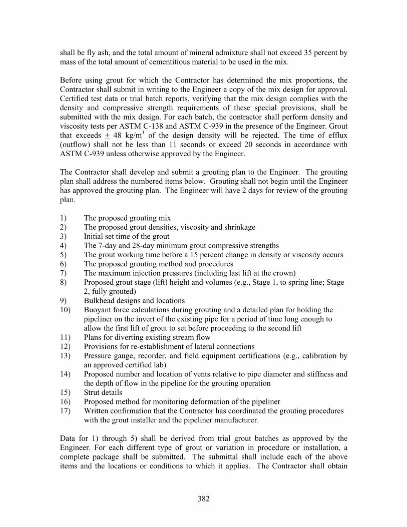
382
shall be fly ash, and the total amount of mineral admixture shall not exceed 35 percent by mass of the total amount of cementitious material to be used in the mix.
Before using grout for which the Contractor has determined the mix proportions, the Contractor shall submit in writing to the Engineer a copy of the mix design for approval. Certified test data or trial batch reports, verifying that the mix design complies with the density and compressive strength requirements of these special provisions, shall be submitted with the mix design. For each batch, the contractor shall perform density and viscosity tests per ASTM C-138 and ASTM C-939 in the presence of the Engineer. Grout that exceeds + 48 kg/m3 of the design density will be rejected. The time of efflux (outflow) shall not be less than 11 seconds or exceed 20 seconds in accordance with ASTM C-939 unless otherwise approved by the Engineer.
The Contractor shall develop and submit a grouting plan to the Engineer. The grouting plan shall address the numbered items below. Grouting shall not begin until the Engineer has approved the grouting plan. The Engineer will have 2 days for review of the grouting plan.
1) The proposed grouting mix 2) The proposed grout densities, viscosity and shrinkage 3) Initial set time of the grout 4) The 7-day and 28-day minimum grout compressive strengths 5) The grout working time before a 15 percent change in density or viscosity occurs 6) The proposed grouting method and procedures 7) The maximum injection pressures (including last lift at the crown) 8) Proposed grout stage (lift) height and volumes (e.g., Stage 1, to spring line; Stage
2, fully grouted) 9) Bulkhead designs and locations 10) Buoyant force calculations during grouting and a detailed plan for holding the
pipeliner on the invert of the existing pipe for a period of time long enough to allow the first lift of grout to set before proceeding to the second lift
11) Plans for diverting existing stream flow 12) Provisions for re-establishment of lateral connections 13) Pressure gauge, recorder, and field equipment certifications (e.g., calibration by
an approved certified lab) 14) Proposed number and location of vents relative to pipe diameter and stiffness and
the depth of flow in the pipeline for the grouting operation 15) Strut details 16) Proposed method for monitoring deformation of the pipeliner 17) Written confirmation that the Contractor has coordinated the grouting procedures
with the grout installer and the pipeliner manufacturer.
Data for 1) through 5) shall be derived from trial grout batches as approved by the Engineer. For each different type of grout or variation in procedure or installation, a complete package shall be submitted. The submittal shall include each of the above items and the locations or conditions to which it applies. The Contractor shall obtain

383
approval from the Engineer for any changes to be made in grout mix, grouting procedure, or installation prior to commencement of grouting operations.
The gauged pumping pressure shall not exceed 35 kPa or manufacturer’s recommendation for spiral wound PVC pipe liners (fixed diameter) with a pipe stiffness of less than 200 kPa and shall not exceed 50 kPa for all other PVC pipe liners (fixed diameter) without steel reinforcement. Grouting pressure shall not exceed 70 kPa for spiral wound PVC pipe liners (fixed diameter) with steel reinforcement. In addition, the PVC pipeliner (fixed diameter) shall be able to withstand a static head of grout of 150 mm above the highest crown elevation. Maximum grout pressure for static grout head shall not exceed maximum allowable gauged pumping pressure for the spiral wound PVC pipe liner (fixed diameter). The grout shall be placed in a continuous manner and injected in lifts not exceeding the height designated in the grouting plan approved by the Engineer, or less if needed to avoid floating, shifting or deforming the spiral wound PVC pipe liner (fixed diameter). The injection pressure including the last lift at the crown shall be carefully monitored. If the spiral wound PVC pipe liner (fixed diameter) cannot withstand the grouting pressures or static head, then the maximum pressure at the point of grout injection must be reduced or staged grouting must be employed, or an alternative pipeliner selected. Deformation the spiral wound PVC pipe liner (fixed diameter) shall not exceed 5%. The Contractor's placement method shall prevent segregation or voids from occurring in the grout mix.
Prior to grouting, the existing culvert shall be free from water and debris. Grouting shall not begin until the existing stream flow has been temporarily diverted and approved bulkheads installed. Grout injection tubes and breather tubes shall be placed around the liner and through the bulkheads.
As approved by the Engineer, grout injection holes of up to 50 mm in diameter may also be drilled at appropriate points in the spiral wound PVC pipe liner (fixed diameter), plugged with PVC plugs and sealed in place with a bead of approved sealant/adhesive.
Spiral-wound PVC liner (fixed diameter) work to be performed under these specifications will be listed in the contract item by size, type, or whatever information is necessary for identification. Quantities of the pipe liner shall be measured by the meter along the slope length of the host pipe as designated on the plans and confirmed by the Engineer. Spiral-wound polyvinyl chloride PVC liner (fixed diameter) placed in excess shall not be paid for. Upon completion of installing the spiral wound PVC pipe liner (fixed diameter) including annular space grouting, ends of the pipe shall be sealed with cement mortar conforming to the provisions in Section 65-1.06, "Joints," of the Standard Specifications. When beveled ends are shown on the plans, exact dimension in millimeters between end of host pipe and spiral-wound PVC liner (fixed diameter), to be determined by the Engineer prior to sealing ends with cement mortar.
Disconnecting of the existing downdrains, designated on the plans or encountered in the field, prior to the installation of the pipe liner may be required at some locations. Full compensation for disconnecting and reconnecting the existing downdrain shall be

384
considered as included in the contract price paid per meter for the various sizes of spiral-wound PVC liner (fixed diameter) in the Engineer’s estimate and no additional compensation will be allowed therefore.
The contract price paid per meter for the different sizes of spiral wound PVC pipe liner (fixed diameter) shall include full compensation for furnishing all labor, materials (including grout), tools, equipment, and incidentals, and for doing all the work involved in installing spiral wound PVC pipe liner (fixed diameter), complete in place, including cleaning of existing culverts of obstructions, re-establishing all existing connections, annular space grouting, providing samples, repairing defects (except for removal of obstructions that cannot be removed by conventional equipment and cleaners), cutting, removing, and disposing of a portion of host pipes where spiral-wound PVC liner (fixed diameter) is to be installed and performing two closed circuit television inspections, grouting and submitting the grout mix design and grouting plan, diverting existing stream flow, cleaning existing culverts and disposal of residue from cleaning, as shown on the plans, as specified in the Standard Specifications and these special provisions, and as directed by the Engineer.
Cement mortar conforming to the provisions in Section 65-1.06, "Joints," of the Standard Specifications, shall be placed to form a seal between the existing culvert and the spiral wound PVC pipe liner, as shown on the plans. Pipe for the weep tube shall be commercial quality, rigid, plastic pipe. When beveled ends are shown on the plans, exact dimension in millimeters between end of host pipe and spiral-wound PVC liner (fixed diameter), to be determined by the Engineer prior to sealing ends with cement mortar.
Paper or cloth wadding shall be placed not less than 150 mm from each end of the existing pipe, as shown on the plans, to retain the mortar during sealing operations.
Spiral-wound polyvinyl chloride (PVC) liner (fixed diameter) work to be performed under these specifications will be listed in the contract item by size, type, or whatever information is necessary for identification. Quantities of the pipe liner shall be measured by the meter along the slope length of the host pipe as designated on the plans and confirmed by the Engineer. Liner placed in excess shall not be paid for.
Disconnecting of the existing downdrains, designated on the plans or encountered in the field, prior to the installation of the pipe liner may be required at some locations. Full compensation for disconnecting and reconnecting the existing downdrain shall be considered as included in the contract price paid per meter for the various sizes of spiral-wound polyvinyl chloride (PVC) liner (fixed diameter) in the Engineer’s estimate and no additional compensation will be allowed therefore.

385
APPENDIX H: Cone Penetration Test (CPT) Investigations

386
H.1 Introduction
Cone penetration test (CPT) is a field test in which a 1.75-inch (44.5-mm) diameter steel
shaft with a 60˚ conical tip is hydraulically pushed into the ground to collect various
subsurface data. This technology, developed originally in Europe, is becoming a premier
subsurface exploration method in North America for the fields of geotechnical
engineering, earthquake engineering, and environmental engineering. The rising
popularity of CPT is due to the fact that it can provide much higher resolution data than
any of the conventional test methods (such as SPT). CPT is cleaner than the traditional
drilling based methods, bringing no spoil to the ground surface. The probe located near
the tip can accept many different sensors and devices to acquire project specific
subsurface information. The standard CPT cone is equipped with strain-gage-based load
cells and a pressure transducer to measure the tip resistance, sleeve friction, and pore
pressure – See Figure H.1. Publications by Meigh (1987) and Robertson and Campanella
(1988) describe the procedures and data interpretation methods for CPT.
G.2 CPT Sounding at Highway Culvert Sites
In the current research project, CPT technology was applied at three highway culvert sites
in Ohio (listed in Table H.1). The first culvert structure (WAR-48-20.95) was a 55-inch
(1,397 mm) diameter corrugated metal pipe. It was not part of the field inspection
program involved in the study. This structure was suggested for the CPT investigation
phase of the project by ODOT personnel who happened to notice its poor conditions
despite its young age. The remaining two culverts were thermoplastic pipe culverts, that
had been inspected in the current research project. Their descriptions and conditions

387
have been presented previously in Chapters 6 and 7. The following sections provide
details of the CPT sounding work performed at each of these sites.
Porous Filter Ring
Tip Resistance
Slee
ve F
rict
ionSleeve
PressureTransducer
MainShaft
ConicalTip
Insi
de C
avit
y
Thrust Force
Soil
Soil
Figure H.1: CPT Penetration Process in Subsurface
Table H.1: List of Culverts Selected for CPT Application No. Culvert Culvert Size Ht. of Cover Notes 1 WAR-48-20.95
(Corrugated Metal) 55” (1,397 mm) Dia.
Approx. 10 ft (3.0 m)
Installed in #8 stone. CPT performed on 11-10-05
2 FAI-33b-Sta. 446+92 (HDPE Pipe)
60” (1,524 mm) Dia.
Approx. 8 ft (2.4 m)
Installed in sand. CPT performed on 3-4-05
3 FAI-33b-Sta. 587+96 (PVC Pipe)
48” (1,219 mm) Dia.
Approx. 17 ft (5.2 m)
Installed in crushed limestone. CPT performed on 3-4-05

388
H.2.1 CPT Sounding at WAR-48-20.95 Culvert Site
H.2.1.1 Initial Inspection of WAR-48-20.95
A reconnaissance trip was made to the site of the metal culvert WAR-48-20.95 on Oct. 8,
2004. The culvert was located just south of a new bridge constructed on Rt. 48, on the
north edge of the City of Lebanon, Ohio. This culvert structure was installed in 2003.
No drainage flow was taking place through the culvert. The metal surface looked new
with no indication of corrosion or pitting anywhere. Some observations made at the site
were:
The culvert consisted of three sections of a non-sectional corrugated metal
pipe with a continuous spiral seam running through it. The corrugated plate
had a pitch of 2-5/8” (67 mm), depth of ½” (13 mm), and a thickness of
0.075” (2 mm). The culvert had a steep slope of 9.5%.
The cross-sectional shape of the culvert looked distorted and unsymmetrical
near Joint 1 (near the outlet end) and near Joint 3 (near the inlet end).
At Joint 1, a gap was present on the invert. The gap appeared to be contained
with a metal coupler. At Joint 3 (close to the inlet end), a 1-inch or 25-mm
offset and a gap existed on the invert. The bedding material (coarse stones)
was visible through the gap.

389
The headwall at the inlet end was a half-height concrete cradle. The headwall
at the outlet end was a tall retaining wall. No major cracks or signs of
movement/rotation were observed on either of the headwalls.
The maximum height of cover appeared to be about 10 ft (3.05 m).
The roadway surface was smooth and free from any dips/cracks.
The diameter measurements taken inside the culvert are presented in Table H.2. The
table indicates that the worst distortion existed near Joint 1. Photographs taken at the site
during the reconnaissance trip are presented below.
Table H.2: Inside Diameters of WAR-48-20.95 Vertical: Horizontal: Distance from Outlet
End Diameter (in.) Deflection (%) Diameter (in.) Deflection (%) 0 (Outlet End) 56.00 + 3.7 53.00 - 1.9
5 ft 55.25 + 2.3 52.75 - 2.3 13 ft 53.00 - 1.9 52.375 - 3.0
24 ft (Near Joint 1) 48.50 - 10.2 56.00 + 3.7 50 ft (Near Joint 2) 53.25 - 1.4 54.50 + 0.9 75 ft (Near Joint 3) 52.25 - 3.2 54.25 + 0.5
85 ft 54.75 + 1.4 55.00 + 1.9 100 ft 54.125 + 0.2 54.00 0.0
102 ft (Inlet End) 54.25 + 0.5 55.00 + 1.9 [Note] 1 inch = 25.4 mm; and 1 ft = 0.305 m

390
Figure H.1: General View of Outlet End
Figure H.2: Cross-sectional Shape of Culvert at Joint 1 (Near Outlet)
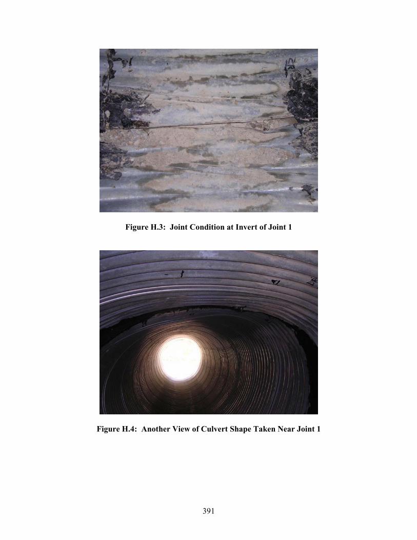
391
Figure H.3: Joint Condition at Invert of Joint 1
Figure H.4: Another View of Culvert Shape Taken Near Joint 1
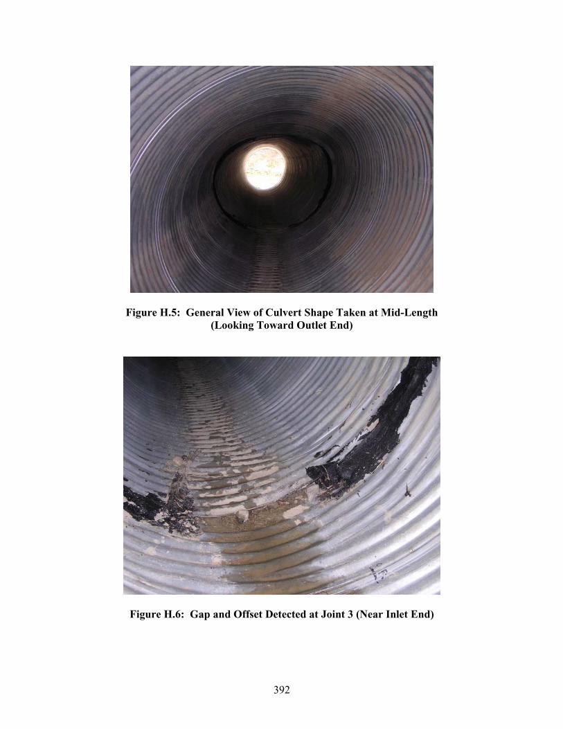
392
Figure H.5: General View of Culvert Shape Taken at Mid-Length (Looking Toward Outlet End)
Figure H.6: Gap and Offset Detected at Joint 3 (Near Inlet End)

393
Figure H.7: General View of Culvert Shape at Inlet End
Figure H.8: General View of Culvert & Headwall at Inlet End

394
Figure H.9: General View of Roadway Surface Over Culvert
Figure H.10: Close-Up View of Pavement Surface Over Culvert
(Note: The white dot on the asphalt surface corresponds to the culvertcrown at Joint 1)

395
Based on the inspection work conducted during the reconnaissance trip, it was decided
that the CPT sounding should be conducted near either Joint 1 or Joint 3 of the culvert.
Joint 1 is located under the white paint mark made on the asphalt surface (as shown in
Figures H.9 and H.10 above). Joint 3 is located under the large grassed area away from
the traffic lanes. Joint 1 location is preferable, since the CPT work there will require
closing of only one traffic lane.
G.2.1.2 CPT Sounding at WAR-48-20.95
The CPT sounding work was performed at the culvert WAR-48-20.95 on Nov. 10, 2004.
According to ODOT personnel:
The original culvert was supposed to withstand up to 60 ft (18.3 m) of soil fill load when installed properly.
One question concerning this culvert was if it had been damaged before it was buried in the ground.
The culvert was rehabilitated 2 weeks prior to the CPT investigation. The contractor who performed the rehabilitation work excavated the inlet end area, removed the top part of the culvert through cutting, inserted a 42-inch (1.07-m) diameter, 0.5-inch (13-mm) thick, solid-wall steel pipe, and grouted the gap.
Before inserting the steel pipe, the contractor drilled small holes over the invert at 4, 6, and 8 o’clock positions every 5 ft (1.52 m) along the culvert length to inject polyurethane into the bedding layer to fill voids in it and stabilize it.
The culvert was supposedly backfilled with ODOT Item 304. However, when the inlet section was excavated, they found AASHTO #8 stones in the area.
The trench width was not measured but was believed to be fairly wide.
396
As soon as the traffic control was set up by ODOT to close one traffic lane, two CPT hole
locations were marked on the asphalt pavement surface near Joint 1, using white spray
paint. A plumb-bob was dropped to the culvert outlet end from the roadway edge to
mark the crown of the culvert along the east edge of the road. A level rod was set up at
the culvert inlet end to establish the crown position along the western edge of the road.
Using these two reference points, a 100-ft (30.5-m) tape was stretched tightly across the
pavement surface. The crown at Joint 1 was marked on this tape by pacing a distance of
24 ft (7.32 m) from the outlet end. Then, the two hole locations were spray-painted on
the roadway surface by taking a distance of 4.5 ft (1.37 m) in each direction,
perpendicularly to the projected culvert centerline. According to the estimations, the
CPT probe should be penetrating through the backfill soil about 2 ft (0.61 m) away from
the culvert. Figure H.11 illustrates the locations of the two CPT holes with respect to the
roadway and culvert. The hole on the north side was identified as Hole #1, and the hole
on the south side was identified as Hole #2. The second task was to punch a hole through
the 12-inch (0.30 m) thick AC layer at each hole location. This was done using a
hammer drill. It took less than 30 minutes to drill 2-inch (50-mm) diameter holes through
the AC layer at the Hole #1 and #2 locations.
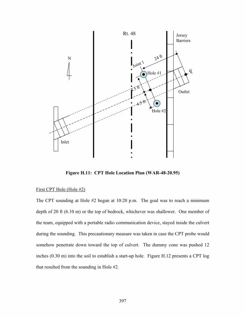
397
Outlet
Inlet
JerseyBarriers
N
CL
Hole #2
Hole #1
24 ft
4.5 ft
4.5 ft
Joint 1
Rt. 48
Figure H.11: CPT Hole Location Plan (WAR-48-20.95)
First CPT Hole (Hole #2)
The CPT sounding at Hole #2 began at 10:20 p.m. The goal was to reach a minimum
depth of 20 ft (6.10 m) or the top of bedrock, whichever was shallower. One member of
the team, equipped with a portable radio communication device, stayed inside the culvert
during the sounding. This precautionary measure was taken in case the CPT probe would
somehow penetrate down toward the top of culvert. The dummy cone was pushed 12
inches (0.30 m) into the soil to establish a start-up hole. Figure H.12 presents a CPT log
that resulted from the sounding in Hole #2.
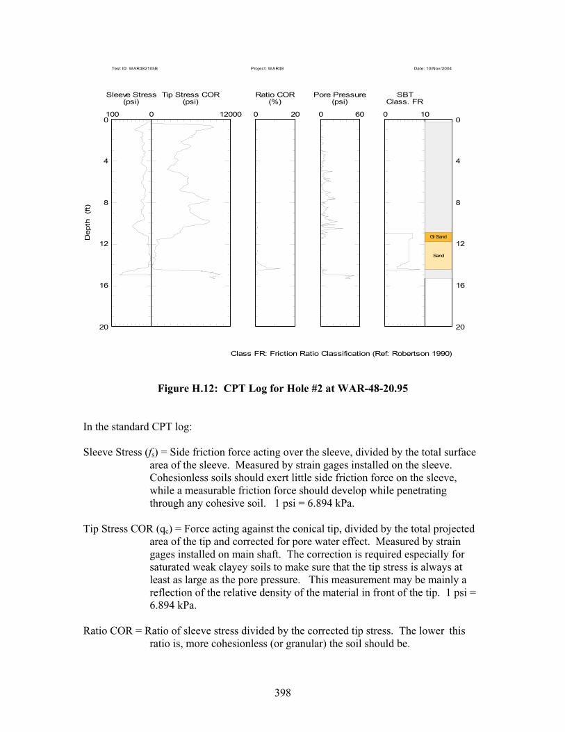
398
100 0
Sleeve Stress(psi)
0 12000
Tip Stress COR(psi)
0 20
Ratio COR(%)
0 60
Pore Pressure(psi)
0 10
SBTClass. FR
Gr Sand
Sand
Depth
(ft)
0 0
4 4
8 8
12 12
16 16
20 20
Class FR: Friction Ratio Classification (Ref: Robertson 1990)
Test ID: WAR482105B Project: WAR48 Date: 10/Nov/2004
Figure H.12: CPT Log for Hole #2 at WAR-48-20.95
In the standard CPT log:
Sleeve Stress (fs) = Side friction force acting over the sleeve, divided by the total surface area of the sleeve. Measured by strain gages installed on the sleeve. Cohesionless soils should exert little side friction force on the sleeve, while a measurable friction force should develop while penetrating through any cohesive soil. 1 psi = 6.894 kPa.
Tip Stress COR (qc) = Force acting against the conical tip, divided by the total projected area of the tip and corrected for pore water effect. Measured by strain gages installed on main shaft. The correction is required especially for saturated weak clayey soils to make sure that the tip stress is always at least as large as the pore pressure. This measurement may be mainly a reflection of the relative density of the material in front of the tip. 1 psi =
6.894 kPa.
Ratio COR = Ratio of sleeve stress divided by the corrected tip stress. The lower this ratio is, more cohesionless (or granular) the soil should be.

399
Pore Pressure (u) = Pore water pressure measured by a pressure transducer housed inside the cone assembly. Cavity leading to the transducer is located right behind the conical tip. This reading should reflect the hydrostatic pressure (that increases linearly with depth) while penetrating through any permeable zone below the groundwater table. Excess pore pressure, that is much larger than the hydrostatic pressure, tends to develop while penetrating through any zone of low permeability. 1 psi = 6.894 kPa.
SBT = Standardized (normalized) friction ratio. Based on the following formula:
100%0
xq
fSBT
vc
s where v0 = effective overburden stress.
Class. FR = Soil behavioral classification based on a chart by Robertson (1990).
OC = Very stiff (or overconsolidated) fine-grained soil. Cl Silt = Normally consolidated clayey silt to silty clay. OC-Clay = Very stiff (or overconsolidated) clay. Gr Sand = Normally consolidated gravely sand to sand.
Once the CPT readings are obtained, a chart similar to the one shown in Figure H.13 is
used to identify the type of soil encountered at any depth.
Figure H.13: Soil Behavioral Classification Chart

400
The culvert was believed to be located from 10 ft (3.1 m) to 15 ft (4.6 m) below the
ground surface. According to the log, the soil behavioral classification method based on
CPT readings identified the backfill to be a sandy soil. Both tip resistance (qc) and sleeve
friction (fs) readings decreased significantly from the depth of 10 ft (3.05 m). The probe
encountered the bedrock at the depth of 14 ft (4.27 m). The truck started lifting itself off
the roadway surface. The sounding of Hole #2 was completed at 11:50 a.m.
Second CPT Hole (Hole #1)
The CPT sounding began at Hole #1 at 12:00 p.m. The goal was to reach a minimum
depth of 20 ft (6.10 m) or the top of bedrock, whichever was shallower. One of the team
members stayed inside the culvert again as a precautionary measure. The dummy cone
was pushed 12 inches (0.30 m) into the soil. Figure H.14 presents a CPT log that resulted
from the sounding in Hole #1. The culvert was believed to be located from 10 ft (3.1 m)
to 15 ft (4.6 m) below the ground surface. The backfill soil type was recognized again
correctly in the log. According to the log, both tip resistance (qc) and sleeve friction (fs)
readings decreased significantly from the depth of 12 ft (3.66 m). The probe encountered
a very stiff layer at 14.7 ft (4.48 m). The truck started lifting off the roadway surface.
The sounding of Hole #1 was completed at 12:30 a.m.

401
50 0
Sleeve Stress(psi)
0 20000
Tip Stress COR(psi)
0 100
Ratio COR(%)
0 20
Pore Pressure(psi)
0 10
SBTClass. FR
Sand
Sand Mix
Depth
(ft)
0 0
3 3
6 6
9 9
12 12
15 15
Class FR: Friction Ratio Classification (Ref: Robertson 1990)
Test ID: WAR482105 Project: WAR48 Date: 10/Nov/2004
Figure H.14: CPT Log for Hole #1 at WAR-48-20.95
Observations at WAR-48-20.95
The team felt that the CPT sounding work conducted at this site was successful. The fact
that the CPT readings decreased significantly while penetrating the backfill soil below the
crown elevation indicated the presence of loose backfill zone next to the culvert.
According to the way the culvert had deformed, it was leaning toward south. This
leaning might have compacted the backfill on the south (Hole #2) side somewhat more
and loosened the backfill on the north (Hole #1) side. Figure H.15 plots the tip resistance
stress measurements recorded in both holes. Figure H.16 plots the tip resistance stress
ratio (Hole #1)/(Hole #2) over the depth range. When these plots are examined closely, it

402
is realized that the tip resistance readings were indeed higher on the south (Hole #2) side
at the depth range corresponding to the culvert depth and rise.
Figure H.15: Tip Resistance Stress Measurements at WAR-48-20.95
Figure H.16: Tip Resistance Stress Ratio Between Holes #1 and #2
0
2
4
6
8
10
12
14
16
0 5000 10000 15000 20000
Tip Stress (psi)
Dep
th (
ft)
Hole #1
Hole #2
0
2
4
6
8
10
12
14
16
0 0.5 1 1.5 2 2.5 3
Tip Stress Ratio (Hole #1/Hole #2)
Dep
th (f
t)

403
Several color photographs taken before the field work at this site are attached here.
Figure H.17: Inlet End of Rehabilitated Culvert
Figure H.18: Interior View of Rehabilitated Culvert
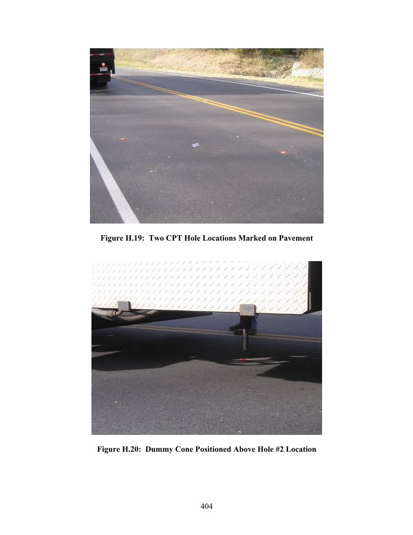
404
Figure H.19: Two CPT Hole Locations Marked on Pavement
Figure H.20: Dummy Cone Positioned Above Hole #2 Location
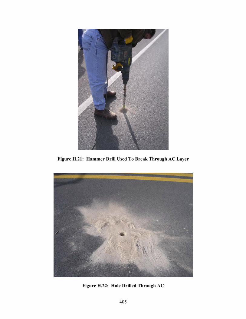
405
Figure H.21: Hammer Drill Used To Break Through AC Layer
Figure H.22: Hole Drilled Through AC
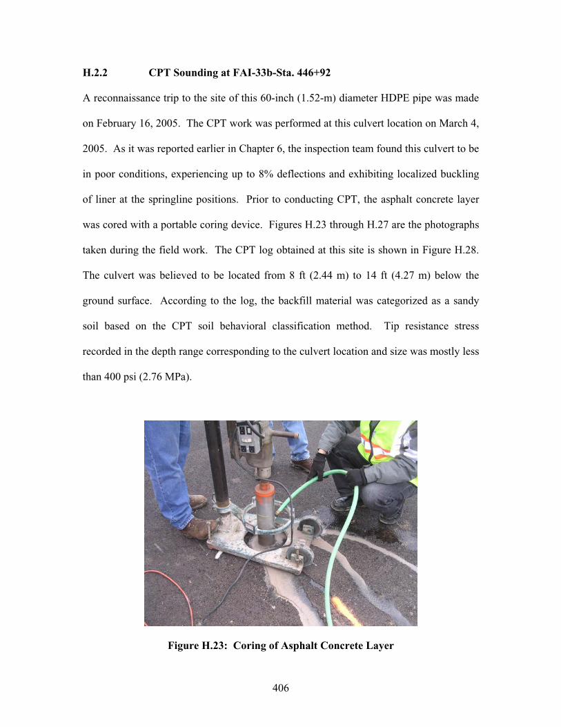
406
H.2.2 CPT Sounding at FAI-33b-Sta. 446+92
A reconnaissance trip to the site of this 60-inch (1.52-m) diameter HDPE pipe was made
on February 16, 2005. The CPT work was performed at this culvert location on March 4,
2005. As it was reported earlier in Chapter 6, the inspection team found this culvert to be
in poor conditions, experiencing up to 8% deflections and exhibiting localized buckling
of liner at the springline positions. Prior to conducting CPT, the asphalt concrete layer
was cored with a portable coring device. Figures H.23 through H.27 are the photographs
taken during the field work. The CPT log obtained at this site is shown in Figure H.28.
The culvert was believed to be located from 8 ft (2.44 m) to 14 ft (4.27 m) below the
ground surface. According to the log, the backfill material was categorized as a sandy
soil based on the CPT soil behavioral classification method. Tip resistance stress
recorded in the depth range corresponding to the culvert location and size was mostly less
than 400 psi (2.76 MPa).
Figure H.23: Coring of Asphalt Concrete Layer

407
Figure H.24: CPT Truck Parked in Shoulder Section
Figure H.25: CPT Truck Positioned over FAI-33b-Sta. 446+92

408
Figure H.26: CPT Getting Ready to Penetrate into Ground
Figure H.27: Hydraulic Push Frame Operating Inside CPT Truck
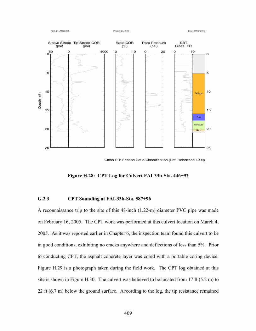
409
50 0
Sleeve Stress(psi)
0 4000
Tip Stress COR(psi)
0 10
Ratio COR(%)
0 20
Pore Pressure(psi)
0 10
SBTClass. FR
Gr Sand
Clay
Sand Mix
Sand
Depth
(ft)
0 0
5 5
10 10
15 15
20 20
25 25
Class FR: Friction Ratio Classification (Ref: Robertson 1990)
Test ID: LANC33E1 Project: LANC33 Date: 04/Mar/2005
Figure H.28: CPT Log for Culvert FAI-33b-Sta. 446+92
G.2.3 CPT Sounding at FAI-33b-Sta. 587+96
A reconnaissance trip to the site of this 48-inch (1.22-m) diameter PVC pipe was made
on February 16, 2005. The CPT work was performed at this culvert location on March 4,
2005. As it was reported earlier in Chapter 6, the inspection team found this culvert to be
in good conditions, exhibiting no cracks anywhere and deflections of less than 5%. Prior
to conducting CPT, the asphalt concrete layer was cored with a portable coring device.
Figure H.29 is a photograph taken during the field work. The CPT log obtained at this
site is shown in Figure H.30. The culvert was believed to be located from 17 ft (5.2 m) to
22 ft (6.7 m) below the ground surface. According to the log, the tip resistance remained

410
less than 500 psi (3.45 MPa) from the depth of 11 ft to 23 ft (3.35 m to 7.01 m). The
crushed limestone material was identified as either sand mix or clayey silt by the CPT
soil behavioral classification method.
Figure H.29: CPT Truck Positioned over FAI-33b-Sta. 587+96

411
200 0
Sleeve Stress(psi)
0 8000
Tip Stress COR(psi)
0 100
Ratio COR(%)
0 10
Pore Pressure(psi)
0 10
SBTClass. FR
Gr Sand
Sand MixSand Mix
Cl Silt
Sand Mix
ClayClay
Sand MixClay
Cl Silt
Clay
Clay
Sand MixCl Silt
Cl Silt
Cl Silt
Depth
(ft)
0 0
5 5
10 10
15 15
20 20
25 25
Class FR: Friction Ratio Classification (Ref: Robertson 1990)
Test ID: LANC33E2 Project: LANC33 Date: 04/Mar/2005
Figure H.30: CPT Log for FAI-33b-Sta. 587+96
G.3 Concluding Remarks
During the current research project, it was demonstrated at the three highway culvert sites
that the cone penetration test (CPT) can be a useful tool for evaluating the quality of
backfill soil envelope placed around the culvert. The zone of weak (or loose) soil or
voids near the culvert can be easily identified, without open excavation, through
significant declines in the tip resistance (qc) and sleeve friction (fs) readings. From the
CPT readings the type of backfill soil can be estimated (if it is unknown).

412
In most cases, the CPT sounding can be achieved relatively quickly (within 1 hour per
hole) while closing only one traffic lane. The only difficulty associated with the
application of CPT is that prior to each sounding the hole location must be carefully
determined on the roadway surface, so that the CPT probe will penetrate within a few feet
of the culvert structure. The CPT hole can be positioned with confidence when the height
of cover over the culvert is less than 10 ft (3.05 m). The positioning of the sounding
location becomes increasingly more challenging as the height of cover increases beyond
10 ft (3.05 m). It is recommended that a modern survey technique or GPS technology be
applied to place the sounding holes when the height of soil cover exceeds 20 ft (6.10 m).
Additional research work is needed to establish a set of data that can be used to correlate
the CPT tip resistance readings and the relative compaction (or dry unit weight) for each
type of commonly used backfill materials.
ORITE 114 Stocker Center Athens, Ohio 45701-2979 740-593-2476 Fax: 740-593-0625 [email protected] http://webce.ent.ohiou.edu//orite/