rite aid corporation (rid) -...
TRANSCRIPT

Hughes Network Systems 11717 Exploration Lane
Germantown, MD 20876 Tel: (301) 428-5500
January 2007 Fax: (301) 601-7407
Rite Aid Corporation
(RID)
HN7700S New Installation Specification (Brooks and Eckerd Stores)
Revision A 01/19/07

Rev. A 01/19/07 RID Installation Specification
i
Copyright © 2006 Hughes Network Systems, LLC All rights reserved. This publication and its contents are proprietary to Hughes Network Systems, LLC. No part of this publication may be reproduced in any form or by any means without the written permission of Hughes Network Systems, LLC, 11717 Exploration Lane, Germantown, Maryland, 20876. Hughes Network Systems has made every effort to ensure the correctness of the materials in this document. Hughes Network Systems shall not be liable for errors contained herein. The information in this document is subject to change without notice. Hughes Network Systems makes no warranty of any kind with regard to this material, including, but not limited to, the implied warranties or merchantability and fitness for a particular purpose.
Trademarks Hughes, Hughes Network Systems, and HughesNet are trademarks of Hughes Network Systems, LLC. All other trademarks contained in this document are the property of their respective owners.
Scope of Document This installation specification is not intended to be an all-inclusive document. Rather, it is only to be used to identify to the installer those installation-related items that are specific to the customer. In order to keep this document concise, installation-related issues that are general in nature are not covered in this document. While every attempt is made to ensure the accuracy of this specification, some information in this document may change without notice. It is the installer’s responsibility to ensure that they verify, and have, current information regarding a specific site. If you discover errors within this document, contact [email protected] for additions or changes. Provide the specification title, page number, section number, and error in question. If practical, provide a viable solution to rectify the error.
Notice of Proprietary Information This document and its contents are proprietary to the issuer and are intended solely for the contractual use of the issuer’s customers. This publication and its contents may not be reproduced or distributed for any other purposes without the written permission of the issuer.
Revision History Revision Date Document Changes
A 01/19/07 Initial release

Rev. A 01/19/07 RID Installation Specification
ii
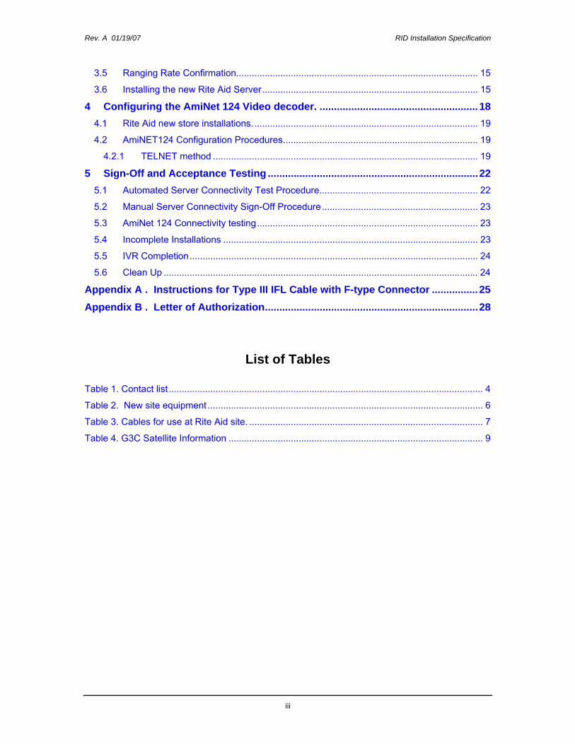
Table of Contents
1 General Information .................................................................................................4 1.1 Supplier ............................................................................................................................. 4 1.2 Customer........................................................................................................................... 4 1.3 Coordination...................................................................................................................... 4 1.4 Scope................................................................................................................................ 4 1.5 Background....................................................................................................................... 4 1.6 Installer Support................................................................................................................ 5 1.7 Hughes, customer-, and contractor-supplied equipment.................................................. 6
1.7.1 HN7700S™ Equipment ............................................................................................. 6 1.7.2 Customer-supplied equipment................................................................................... 7 1.7.3 Contractor-supplied equipment.................................................................................. 8
1.8 Reference Materials.......................................................................................................... 9 1.9 Satellite and NOC Information .......................................................................................... 9 1.10 Antenna Polarization Adjustment.................................................................................... 10 1.11 Hours of Installation Activity............................................................................................ 10 1.12 Site Scheduling ............................................................................................................... 10
1.12.1 Rescheduling ........................................................................................................... 10 1.12.2 Cancellations ........................................................................................................... 11 1.12.3 Site Manager Advisement........................................................................................ 11 1.12.4 Installation Status Update Hotline Advisement........................................................ 11
1.13 Non-Standard Installations.............................................................................................. 11 1.14 Cautions.......................................................................................................................... 11 1.15 Telephone Site Survey.................................................................................................... 11
2 Installation Requirements......................................................................................12 2.1 HN7700S Location.......................................................................................................... 12 2.2 Antenna Location ............................................................................................................ 12 2.3 De-Ice and De-Ice Electric .............................................................................................. 12 2.4 Point of Entry and Cable Installation............................................................................... 13
2.4.1 Point of Entry ........................................................................................................... 13 2.4.2 Drip Loops................................................................................................................ 13
3 HN7700S Installation Procedure ...........................................................................14 3.1 Antenna and Mount Installation ...................................................................................... 14 3.2 IFL Cabling Instructions .................................................................................................. 14 3.3 HN7700S Installation ...................................................................................................... 14 3.4 HN7700S Commissioning Overview............................................................................... 14
Rev. A 01/19/07 RID Installation Specification
iii
3.5 Ranging Rate Confirmation............................................................................................. 15 3.6 Installing the new Rite Aid Server................................................................................... 15
4 Configuring the AmiNet 124 Video decoder. .......................................................18 4.1 Rite Aid new store installations....................................................................................... 19 4.2 AmiNET124 Configuration Procedures........................................................................... 19
4.2.1 TELNET method ...................................................................................................... 19 5 Sign-Off and Acceptance Testing .........................................................................22
5.1 Automated Server Connectivity Test Procedure............................................................. 22 5.2 Manual Server Connectivity Sign-Off Procedure............................................................ 23 5.3 AmiNet 124 Connectivity testing..................................................................................... 23 5.4 Incomplete Installations .................................................................................................. 23 5.5 IVR Completion............................................................................................................... 24 5.6 Clean Up ......................................................................................................................... 24
Appendix A . Instructions for Type III IFL Cable with F-type Connector ................25 Appendix B . Letter of Authorization..........................................................................28
List of Tables
Table 1. Contact list ......................................................................................................................... 4 Table 2. New site equipment .......................................................................................................... 6 Table 3. Cables for use at Rite Aid site. .......................................................................................... 7 Table 4. G3C Satellite Information .................................................................................................. 9

Rev. A 01/19/07 RID Installation Specification
4
1 General Information
1.1 Supplier
Hughes Network Systems, LLC. (Hughes)
1.2 Customer
Rite Aid Corporation (RID)
1.3 Coordination
Table 1. Contact list
Hughes Program Manager: Paul Hlavlinka (301) 428-7382 [email protected]
Hughes Order Administrator: Joe Hall (301) 428-5737 [email protected]
Hughes Program Engineer: Thurman Xu (301) 428- 5937 [email protected]
Hughes Customer Services: (866) 889-3234
RID FSS Help Desk 1-800-843-0831 Silent option 7
RID NOC Help Desk 1-717-975-5828 Option 1
1.4 Scope
This document defines the requirements and instructions for installing Hughes HN7700S systems at new Rite-Aid stores locations throughout the United States, Puerto Rico and Canada. These new stores are currently Brooks and Eckerd Stores.
1.5 Background
Rite Aid Corporation is a retail drugstore chain in the United States serving customers in 30 states across the country and in the District of Columbia.
Rev. A 01/19/07 RID Installation Specification
5
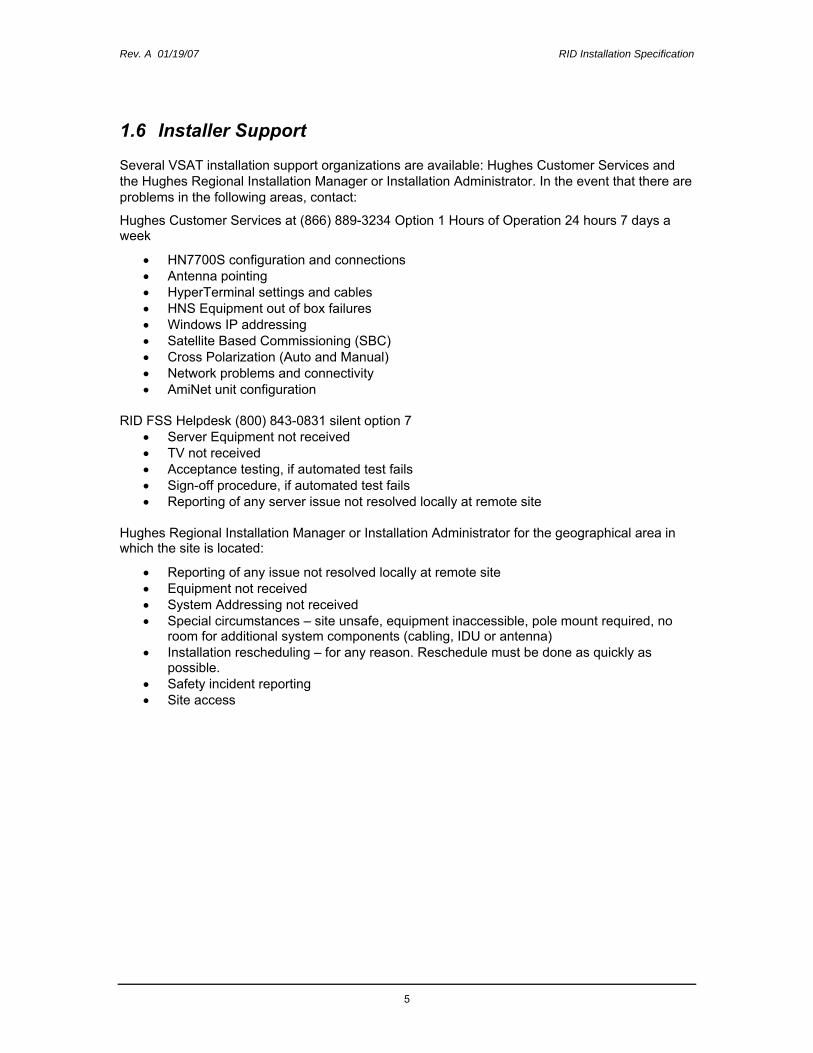
1.6 Installer Support
Several VSAT installation support organizations are available: Hughes Customer Services and the Hughes Regional Installation Manager or Installation Administrator. In the event that there are problems in the following areas, contact:
Hughes Customer Services at (866) 889-3234 Option 1 Hours of Operation 24 hours 7 days a week
• HN7700S configuration and connections • Antenna pointing • HyperTerminal settings and cables • HNS Equipment out of box failures • Windows IP addressing • Satellite Based Commissioning (SBC) • Cross Polarization (Auto and Manual) • Network problems and connectivity • AmiNet unit configuration
RID FSS Helpdesk (800) 843-0831 silent option 7 • Server Equipment not received • TV not received • Acceptance testing, if automated test fails • Sign-off procedure, if automated test fails • Reporting of any server issue not resolved locally at remote site
Hughes Regional Installation Manager or Installation Administrator for the geographical area in which the site is located:
• Reporting of any issue not resolved locally at remote site • Equipment not received • System Addressing not received • Special circumstances – site unsafe, equipment inaccessible, pole mount required, no
room for additional system components (cabling, IDU or antenna) • Installation rescheduling – for any reason. Reschedule must be done as quickly as
possible. • Safety incident reporting • Site access

Rev. A 01/19/07 RID Installation Specification
6
1.7 Hughes, customer-, and contractor-supplied equipment Note: While every attempt is made to ensure the accuracy of these listed parts, some part numbers and
quantity required may change without notice. Always refer to your work order to ensure that you have current part numbers regarding a specific site.
1.7.1 HN7700S™ Equipment
Table 2. New site equipment
Hughes Part Description Quantity 1500138-0005 HN7700S IDU Kit 1 1500172-0202 2.0 Watt Pure ANUBIS RFU Outdoor Unit 1 1034863-0001 .98m Ku/Ka-ready upgradeable antenna See W/O 1035788-0001 .98m Ku/Ka-ready upgradeable antenna, anti-ice See W/O 1034864-0001 1.2m Ku/Ka-ready upgradeable antenna See W/O 1035789-0001 1.2m Ku/Ka-ready upgradeable antenna, anti-ice See W/O 9011226-0011 1.8m antenna See W/O 9012417-0001 6.5X6.5 NPM w/pad, Ka-Ready for 1.2m, 2.88” mast See W/O 9011386-0006 4X4 NPM w/pad, Ka-Ready for .98m, 2.38” mast See W/O 3001506-0001 10X10 NPM w/pad, Ka-Ready for 1.8m, 4” mast See W/O 1036888-0001 Wall Mount Bracket As needed 1037280-0005 AmiNET 124 Set-top box 1 9012941-0001 Enclosure Box (Perfect Vision P/N PVCB1GRY) 1 9006284-0009 Connector for the 1010809-0001 (two connectors per pack) 2 packs per site
IFL Cable (see Table 3) Only 1010809-0001 may be used indoors As needed sbc_RID011907.cfg SBC file 1

Rev. A 01/19/07 RID Installation Specification
7
The only IFL cable and connectors approved for Rite Aid sites can be found in Table 3 below. The table also shows the total length of cable allowed for the entire cable run. This is the cable used indoors 11010809-0001 plus the cable used outdoors. The maximum length is any combination of the two cables.
Example:
150 feet of 10101809-0001 + 125 feet of CommScope 5781= 275 feet. or 100 feet of 10101809-0001 + 82 feet of Perfect 10 ULPVRG6SCDUAL = 182 feet.
Table 3. Cables for use at Rite Aid site.
Cable used indoor Hughes Part Number Cable used outdoors Vendor Part Number Max length (feet)
1010809-0001 Type III Plenum Cable Added to CommScope 5781 276 1010809-0001 Type III Plenum Cable Added to CommScope 5782 276
1010809-0001 Type III Plenum Cable Added to Perfect 10 ULPVRG6SCBLK 182
1010809-0001 Type III Plenum Cable Added to Perfect 10 ULPVRG6SCDUAL 182
1010809-0001 Type III Plenum Cable Added to Perfect 10 ULPVRG6SCQUAD 231
1010809-0001 Type III Plenum Cable Added to Perfect 10 ULPVRG6SCDLQD 231
1010809-0001 Type III Plenum Cable Added to Vextra V621 259 1010809-0001 Type III Plenum Cable Added to Vextra V2621 259 1010809-0001 Type III Plenum Cable Added to Vextra V2621GW 259
Note: The 1010809-0001 Type III Plenum Cable uses the 9006284-0009 connectors. The connectors must be installed using the CablePrep Crimp tool HCT 231.
Refer to Appendix A for the connector assembly instructions excerpted from FSB 1196C.
1.7.2 Customer-supplied equipment
A pallet of equipment will be sent to each store from Rite Aid containing:
• One DELL 2900 server with mouse and keyboard. • One DELL Flat Panel monitor • One 24 port 3COM switch • One APC UPS • Four (7-foot) Cat5 patch cables (orange, green, red, gray) • Two Power Strips • One RF Modulator • One Splitter • One Creative Labs external sound card • One pair speakers • Two coaxial cables • 13-inch TV/VCR

Rev. A 01/19/07 RID Installation Specification
8
If any equipment is missing please call Rite Aid Field Systems Support at 1-800-843-0831 and select hidden option 7. (Note: see section below for instructions on testing connectivity without the server).
1.7.3 Contractor-supplied equipment
• Surface-mount cable raceway (i.e. Wiremold, Panduit, etc). Fish the IFL through the wall; otherwise use surface-mounted cable raceway to hide the cables from view. Do not dangle the IFL from the ceiling or wall in the manager’s office.
• Red (receive) and blue (transmit) electrical tape for labeling IFL cables.
• Weather Tape or Vapor Wrap is required for all outdoor fittings.
• Large 9x6x4 inch enclosure box. If not using the P/N 9012941-0001 enclosure.
• Extra-large UV rated tie wraps for securing the enclosure box. All fasteners needed to mount the enclosure box.
• As needed, Velcro strips to secure the AmiNET units to the TV.
• Waterproof sealants as needed to seal the back of the enclosure box
• Ground antenna and IFL cables in accordance with Field Service Bulletin FSB_050518_01C HNS Broadband Requirements for RG-6 and RG-11 IFL Cable Connectors, Ground Blocks and Ground Block Location.
• Sufficient ballast for Non-Penetrating Roof Mounts in accordance with Hughes guidelines and the Version 1.2.0 Ballast Calculation Tool (Hughes P/N 1036398-0001).

Rev. A 01/19/07 RID Installation Specification
9
1.8 Reference Materials
This section provides a list of documents and internet URLs which may be required, in addition to this installation specification, for the successful completion of the HN7700S installation.
• HN7700S Installation Guide 1037072-0001 • HN7700S User Guide 1037073-0001 • HN7700S Supplemental User Guide 1037075-0001 • FSB_060316_01 - IFL Cable, Approved List (with lengths) for DW7x00, DW60xx, and
DW40xx Domestic Installations • FSB_050518_01 RG-6 IFL Cables and Antenna Grounding • FSB 1196C IFL Cable and Connectors for PES 5000 and DW2000 (MMV) – Update for
RG-6 and “F” connectors. • http://elearning.HughesNet.com
1.9 Satellite and NOC Information
All sites will be commissioned on the Rite Aid NOC using G3C (95º West) as the primary satellite. Table 4 provides the general satellite and NOC parameters necessary for Satellite-Based Commissioning. The complete satellite pointing information, including transponder info will be downloaded during the Commissioning process.
There must be an unobstructed line-of-sight to the satellite as well as the full satellite arc (83°W to 127°W). Verify that trees (growing or bare) and future buildable lots will not obstruct the line-of-sight. Report any line-of-sight problems or obstructions to the appropriate Hughes Installation Manager.
Contact Information: Hughes Customer Services: (866) 889-3234
Table 4. G3C Satellite Information
Satellite: G3C
Location: 95° West
Transponder: 23 Ku-band
L-Band Frequency: 1402.5 MHz
Receive Symbol Rate: 8 Msps
Receive Polarization: Horizontal
Transmit Polarization: Horizontal
22kHz Tone: Off
Viterbi Mode: Auto
Mode DBS-2
Rev. A 01/19/07 RID Installation Specification
10
1.10 Antenna Polarization Adjustment
All HughesNet installer software calculates the polarization for use with antennas that use the Pure ISIS or Pure OSIRIS RFUs. A polarization adjustment will be needed for antennas with TG-style radios.
For 1.0m rectangular antennas: The vertical polarization offset is set on the RFU by setting the polarization on the RFU rings to ±90° degrees. The polarization value calculated from the installer software must be multiplied by -1 and then adjusted by rotating the antenna. The feedhorn must always be vertical with respect to the long axis of the antenna. See Example Below.
For round antennas that use the TG-style RFUs: Compute the correct polarization value by multiplying the value from the DW installer software by -1 and then adding (for sites east of 89ºW) or subtracting (for sites west of 89ºW) 90 degrees. See Example Below.
Polarization Adjustment for Enterprise AntennasExample for 117.1W 33.5N on 89º IA8 Vertical Polarization
Conversion Method TG-style RFU 1.0m Rect.Computed Polarization from DW software -29.5 -29.5Multiply by -1 29.5 29.5Convert to Vertical Polarization ±90° -60.5 Set RFU to 90ºFinal Value -60.5 29.5
1.11 Hours of Installation Activity
Sites will be available for installation activity from 8 a.m. to 8 p.m. local time Monday through Friday. Other times may be arranged.
1.12 Site Scheduling
All work order activity must be tentatively scheduled through the Consumer and Commercial Installation Portal (https://dwayinstalls.hns.com/start/login.jsp) within 24 hours of notification on Web Site of work order issuance. Confirmed schedules must be entered in portal the Wednesday prior to the confirmed scheduled week. Additionally, the installer must reconfirm installation with the Point of Contact 24-48 hours prior to the site visit.
1.12.1 Rescheduling
If you must reschedule an installation appointment for any reason, notify the Rite Aid point of contact (POC) to establish mutually acceptable arrangements. This must be accomplished at the earliest possible time. Update the Consumer and Commercial Installation Portal (https://dwayinstalls.hns.com/start/login.jsp) immediately upon reschedule.
If, after three attempts, you are unable to reschedule with the Point of Contact, notify the Hughes Regional Installation Manager.
Rev. A 01/19/07 RID Installation Specification
11
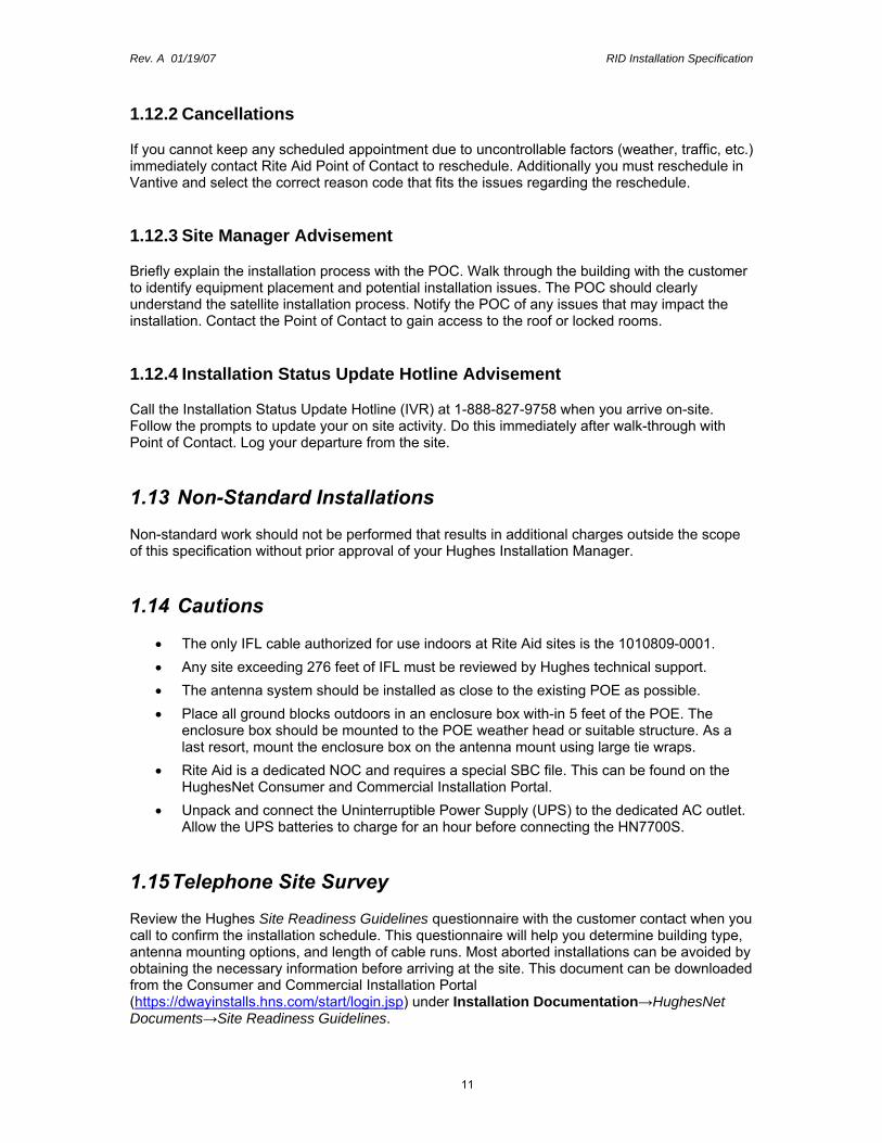
1.12.2 Cancellations
If you cannot keep any scheduled appointment due to uncontrollable factors (weather, traffic, etc.) immediately contact Rite Aid Point of Contact to reschedule. Additionally you must reschedule in Vantive and select the correct reason code that fits the issues regarding the reschedule.
1.12.3 Site Manager Advisement
Briefly explain the installation process with the POC. Walk through the building with the customer to identify equipment placement and potential installation issues. The POC should clearly understand the satellite installation process. Notify the POC of any issues that may impact the installation. Contact the Point of Contact to gain access to the roof or locked rooms.
1.12.4 Installation Status Update Hotline Advisement
Call the Installation Status Update Hotline (IVR) at 1-888-827-9758 when you arrive on-site. Follow the prompts to update your on site activity. Do this immediately after walk-through with Point of Contact. Log your departure from the site.
1.13 Non-Standard Installations
Non-standard work should not be performed that results in additional charges outside the scope of this specification without prior approval of your Hughes Installation Manager.
1.14 Cautions
• The only IFL cable authorized for use indoors at Rite Aid sites is the 1010809-0001. • Any site exceeding 276 feet of IFL must be reviewed by Hughes technical support. • The antenna system should be installed as close to the existing POE as possible. • Place all ground blocks outdoors in an enclosure box with-in 5 feet of the POE. The
enclosure box should be mounted to the POE weather head or suitable structure. As a last resort, mount the enclosure box on the antenna mount using large tie wraps.
• Rite Aid is a dedicated NOC and requires a special SBC file. This can be found on the HughesNet Consumer and Commercial Installation Portal.
• Unpack and connect the Uninterruptible Power Supply (UPS) to the dedicated AC outlet. Allow the UPS batteries to charge for an hour before connecting the HN7700S.
1.15 Telephone Site Survey
Review the Hughes Site Readiness Guidelines questionnaire with the customer contact when you call to confirm the installation schedule. This questionnaire will help you determine building type, antenna mounting options, and length of cable runs. Most aborted installations can be avoided by obtaining the necessary information before arriving at the site. This document can be downloaded from the Consumer and Commercial Installation Portal (https://dwayinstalls.hns.com/start/login.jsp) under Installation Documentation→HughesNet Documents→Site Readiness Guidelines.

Rev. A 01/19/07 RID Installation Specification
12
If, while reviewing the questionnaire, you determine the site is likely a "non-standard" installation, contact your Regional Installation Manager or Administrator for survey authorization.
2 Installation Requirements
2.1 HN7700S Location
• Install the HN7700S, the new Rite Aid server, and TV in the manager’s office. Ensure there is adequate space for all equipment. Work with the Manager as needed.
• The HN7700S is powered by the APC SmartUPS 750; however the UPS batteries must be allowed to charge approximately an hour before connecting the HN7700S power cord.
• Ensure that the location allows for good air movement and proper ventilation around the HN7700S and Rite Aid server for adequate cooling.
• Leave 15 feet of excess IFL cable in the ceiling or coil neatly and place out of the way.
2.2 Antenna Location
The antenna installation must comply with these requirements:
• Keep the antenna out of sight from the customer areas as much as possible.
• Installer the antenna system as close to an existing point of entry (POE) as possible.
• Place the mount as close to the IFL point of entry as possible in order to reduce the exposed length of IFL.
• Ensure that placement of the mount allows three (3) feet of clearance from any and all serviceable equipment on the roof, if possible. Make sure all access to all service boxes or panels and doors or roof hatches are not restricted by the placement of the antenna and mount.
• It is preferable the antenna be placed in a location accessible by using a 20-foot ladder instead of special equipment (such as lift trucks, scaffolding, etc.). Installations where special equipment is required to reach the antenna must be individually approved by the Hughes Regional Installation Manager prior to installation.
• When placing a non-penetrating roof mount at a site, you must clear the area where the antenna will be placed of stones, debris, etc., so as not to cause a foreign object to penetrate the roof membrane due to the weight of the mount.
• If using an anti-ice antenna, install within 50 feet of the designated outlet.
• There must be an unobstructed line-of-sight to the satellite as well as the full satellite arc (83°W to 127°W). Verify that trees (growing or bare) and future buildable lots will not obstruct the line-of-sight.
2.3 De-Ice and De-Ice Electric
Refer to the work order to determine if the site requires a de-iced antenna. Ensure the de-iced antenna is functional before leaving site. If there is no AC power available at the time of the install, test it by connecting the de-icer to an extension cord and moving the switch to “Bypass” for
Rev. A 01/19/07 RID Installation Specification
13
five (5) minutes. The feedhorn and antenna heater should get warm to the touch. Move the anti-ice switch back to “Auto” and disconnect the extension cord before leaving the site.
All new, existing and conversion sites must have their De-Ice units tested. If the de-iced antenna does not function correctly, check the operation of the electrical outlet. Notify the Hughes Regional Installation Manager with any problems regarding the de-icing system.
2.4 Point of Entry and Cable Installation
No IFL cables may be “dangled” from the ceiling to the equipment. Use Wire Mold where needed to help ensure a clean professional installation. Always use screws with wire mold. No IFL will be ‘flown’ (suspended) between two structures.
2.4.1 Point of Entry
When installing the IFL, use an existing POE such as pitch pockets or ventilation ducts. If no suitable POE is available, consult with the Hughes Installation Manager/Administrator before proceeding. A suitable option must be acceptable to the landlord. A vent pipe is not an acceptable point of entry.
2.4.2 Drip Loops
Note: Leave five (5) feet of excess 1010809-0001 IFL inside the building at the POE. Place all ground blocks outdoors in an enclosure box within five (5) feet of the POE. The enclosure box should be mounted to the POE weather head or suitable structure. As a last resort, mount the enclosure box on the antenna mount using large tie wraps.
Create drip loops where required. Some method of fastening the cable without damage shall be employed to maintain the drip loop’s proper bend radius and prevent cable movement. Use only black UV-rated nylon cable ties outside. Adhesive backed “anchor devices” are not authorized to secure cables to surfaces unless additional support from screws is provided. Use properly sized clamps designed for supporting electrical and electronic cables.

Rev. A 01/19/07 RID Installation Specification
14
3 HN7700S Installation Procedure
3.1 Antenna and Mount Installation
1. Install the antenna and mount in accordance with Section 2.2.
2. Install the new RFU.
3. Verify the polarization of the RFU. See Section 1.10 for instructions.
3.2 IFL Cabling Instructions
1. Pull and terminate two new IFL cables from the antenna to the HN7700S location.
2. Install the grounding block outside the building in the enclosure box. Refer to FSB_050518_01C for details.
3. Route the new 1010809-0001 cable inside the building. Add the connectors to the cables and terminate at the ground block within the enclosure box. Then route the RG6 cable the remaining distance to the antenna system.
4. Place the Outdoor Pointing Interface (OPI) inline with the receive IFL (if necessary).
5. Label the new IFL cables. Mark the receive cable with red electrical tape. Mark the transmit cable with blue tape.
3.3 HN7700S Installation
1. Unbox and locate the HN7700S.
2. Connect the IFL cables and power on the HN7700S.
3. Ensure there is adequate space for the new Rite Aid server that will be installed in section 3.6.
3.4 HN7700S Commissioning Overview
The HN7700S supports Satellite-Based Commissioning which operates over the spacelink and does not require software on the installer’s laptop or a phone line. Satellite-based Commissioning (SBC) is described in this document since it is the preferred method to commission HughesNet products.
Note: Rite Aid has a special SBC file named sbc_RID011907.cgf.
The procedure requires the installer’s laptop to have an Ethernet LAN port and Internet Explorer.
The commissioning process includes:
• Connecting the installer’s laptop to the HN7700S. • Starting the commissioning process. • Re-peaking the antenna for the best satellite signal and ACP levels. • Connecting the HN7700S to the customer’s LAN ports in section 3.6. • Confirming satellite connectivity in section 5.
Rev. A 01/19/07 RID Installation Specification
15
Configure your laptop’s Network Interface Card (NIC) to “Obtain an IP address automatically” so that DHCP will be enabled. This is required before every installation. Failure to do this will result in the installer’s laptop not being able to communicate with the HN7700S.
3.5 Ranging Rate Confirmation
Refer to the Notes section of the Work Order to determine which ranging rate applies to your specific installation. These steps apply to sites using the Hughes Access Continuity 200 (AC200) service plan which will show a maximum Successful Rate of 512K Turbo Code 4/5.
1. In order to verify proper spacelink operation, the rate at which the HN7700S ranges (adjusts power and timing) will be 512k Turbo Code 4/5 on this network. If it does not range to 512k Turbo Code 4/5, call Hughes Customer Services at (866) 889-3234 Option 1.
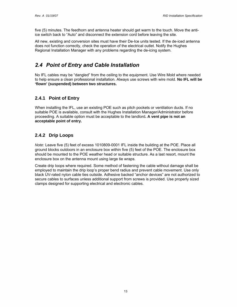
2. Verify the ranging rate by viewing the rate from the HN7700S’s Advanced Configuration and Statistics internal web page. Open Internet Explorer. In the Address Bar type http://192.168.0.1/fs/advanced/advanced.html. It will display the HN7700S System Control Center screen.
3. Click on Ranging Statistics on the left menu. The following screen should be displayed. Confirm that the network shows 512K 4/5.
Figure 1 HN7700S Ranging Statistics
3.6 Installing the new Rite Aid Server
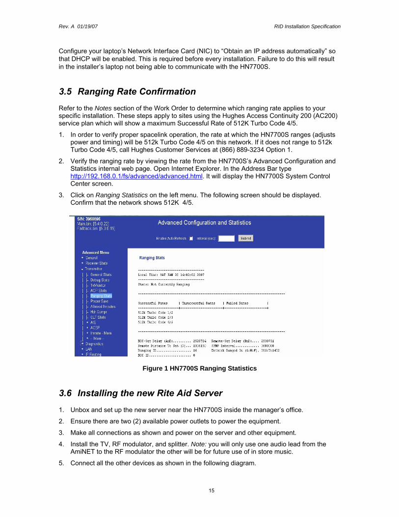
1. Unbox and set up the new server near the HN7700S inside the manager’s office.
2. Ensure there are two (2) available power outlets to power the equipment.
3. Make all connections as shown and power on the server and other equipment.
4. Install the TV, RF modulator, and splitter. Note: you will only use one audio lead from the AmiNET to the RF modulator the other will be for future use of in store music.
5. Connect all the other devices as shown in the following diagram.

Rev. A 01/19/07 RID Installation Specification
16
Note: The diagram shows the sound card going to the bottom right USB port.
Power connection IDU to APC
Primary network connection from server to switch
Dual power supplies from server to APC
Power connection from switch to APC
AC power from power strip to
LCDNetwork
connection RSA card
AC power from power strip to
AmiNET
RF Modulator
AC connection for APC from
wall outlet
AC power from power strip to TV
AC power from power strip to RF
Modulator
SVideo/RCA Y connection from AmiNET to RF
Modulators
Coaxial and splitter connection from RF
Modulator to TVIFL cables
VSAT
LAN 1 connection from
IDU to switch
Network Cable LegendGreen patch cable from LAN1 of IDU to Port 4 of switchRed patch cable from DRAC card of server to port 2 of the switchOrange patch cable from Primary NIC to port 6 of switchGrey patch cable from LAN2 of IDU to AmiNET
VGA connection
USB connection
from server to
sound card
Speaker connection to sound card
labeled “front”Power from speakers to USB port on
server
LAN 2 connection from IDU to
AmiNET
Note: The power button for the Dell PowerEdge 2900 server is behind the removable from panel. Press the “Test” button on the APC UPS to turn the power on.

Rev. A 01/19/07 RID Installation Specification
17
Once the Dell server is booted up, a blue desktop screen should appear (see below). The first five digits should be the Rite Aid store number.
If the store number is incorrect or any other errors appear, call Rite Aid Field Systems Support (1-800-843-0831, choose hidden option 7)for assistance.

Rev. A 01/19/07 RID Installation Specification
18
4 Configuring the AmiNet 124 Video decoder.
The AmiNet 124 was positioned and connected in section 3.6, step 5.

Rev. A 01/19/07 RID Installation Specification
19
4.1 Rite Aid new store installations.
1. Locate the TV that was sent to the store as part of the pallet of Rite Aid. Position the TV with the HN7700S and the server installed in the previous section.
2. Connect the Composite Video cable to the back of the Amino box using the Audio Visual Out port. Connect the Ethernet cable from your laptop to the LAN port if not done is section 3.
3. Plug in the power cord and verify the AmiNET unit is on.
4. Match the color from the AmiNET unit with the video and audio input to the TV.
• Yellow Video • White Audio for the video feed. • Red Audio for the in-store music.
4.2 AmiNET124 Configuration Procedures
4.2.1 TELNET method
1. To verify connectivity, connect your laptop to the new AmiNet110 LAN port (using a LAN crossover cable).
2. Configure your laptop’s Network Interface Card (NIC) to the default IP address assigned to the AmiNET110, as follows:

Rev. A 01/19/07 RID Installation Specification
20
IP Address: 192.168.110.2 Subnet Mask: 255.255.255.252 Default Gateway: 192.168.110.1
3. Open a DOS Command Prompt window:
• For Windows 98SE/Me, click Start → Run and then type command <ENTER>
• For Windows 2000/XP, click Start → Run and then type cmd <ENTER>
4. From the DOS C:\ prompt on the laptop, type ping 192.168.110.1
5. Verify that the address responds with no losses.
6. Again at the DOS C:\ prompt, type telnet 192.168.110.1
7. The login is cfg, the password is cfg2cfg. (all entries are lower-case)
8. From the Main Menu, select option 1, <ENTER>. You’ll need to step through the menu and enter changes as needed.
IMPORTANT NOTE: You may notice a line feed issue once connected to the new AmiNET110 device. This is where more than one option appears on a line.
Example, DHCP [Y] IP Address {192.168.110.2]
To correct this line feed problem using the Telnet program, exit out of the AmiNET110 program by closing the command prompt window and then reopening the command prompt window.
Once you have opened command prompt window and at the ‘C:\’ prompt, type:
• Telnet <ENTER>. • unset crlf <ENTER>.
You will see a new prompt “Microsoft telnet” • Type open 192.168.0.2 and continue from step 7 above.
Below is a continuation of step 8 above:
Enter DHCP (Y/N) [N] : N Enter IP Address [192.168.110.1] : See your Work Order Enter Netmask [255.255.255.252] : 255.255.255.252 Enter Gateway [192.168.110.2] : The LAN 2 address from the HN7700S Enter IPMC Boot Address [239.110.110.110] : {Make 227.0.0.2}

Rev. A 01/19/07 RID Installation Specification
21
Enter IPMC Boot Port [11110] : ( Make 11110) Enter IPMC Upgrade Address [239.110.110.111] : {Make 228.0.0.2} Enter IPMC Upgrade Port [11111] : (Make 11111) Enter IPMC FS Address [239.110.110.111] :{Make 228.0.0.2} Enter IPMC FS Port [11111] : <return> {Make 11111} Enter STB RemoteConf Address [239.110.110.112] : {Make 229.0.0.2} Enter STB RemoteConf Port [11112] : {Make 11112} Enter Channel Address [239.110.110.113] : (Make 225.0.0.2) Enter Channel Port [11113] : 1825 {Make 1825}
Then from the Main Menu:
• Select option 3, then press enter
• Review the changes.
• If everything has been entered correctly, answer ‘Y’ to ‘save and reboot’
• At the bottom of the screen. You will see ‘Connection to Host lost’. You can terminate the ‘telnet’ session.
• Verify audio & video and music.
• If there is no intercom system on site connect the red audio connector for the in-store music to the TV and verify music is playing. You should hear the music playing on top of the video sound.
Note: A HyperTerminal session can also be used. Configure your laptop Ethernet card in the same way as you would for Telnet, under HyperTerminal select New, in the Connect To window select TCP/IP (Winsock), Host Address will be 192.168.110.1, Port Number will be 23. Click on OK. The AmiNET login and password request will appear. These will be the same as found in the Telnet instructions.

Rev. A 01/19/07 RID Installation Specification
22
5 Sign-Off and Acceptance Testing There are two sign-off tests:
1. An automated test for the server
2. A call to the Rite Aid FSS Help Desk to ping the AmiNet box.
5.1 Automated Server Connectivity Test Procedure
Connectivity Test: With the Server booted to the blue desktop with the store number, select Start→Programs→Test VSAT Connection. A successful test displays this screen:
An unsuccessful test displays this screen:
If the test is unsuccessful please contact Rite Aid Field System Support (1-800-843-0831, choose hidden option 7) to reach a representative for assistance.
Record this number and enter it on your Work Order as ‘NOC Sign Off Number.’

Rev. A 01/19/07 RID Installation Specification
23
5.2 Manual Server Connectivity Sign-Off Procedure
Testing connectivity without a server:
Attach the installer’s laptop to the network
From a web browser enter the following URL: http://portal.riteaid.com/ra/raconntst/pages/racn0001.aspx
A successful test displays this screen:
Ensure by this point you have called Rite Aid Field Systems Support to report your issue as noted above. You will be given your confirmation number by FSS at that time.
5.3 AmiNet 124 Connectivity testing
1. Verify there is audio and video on the TV.
2. Verify there is music by connecting the red audio terminal to the TV and listing for music.
3. Contact the Rite Aid FSS Help Desk at 1-800-843-831, silent option 7. The help desk will ping the AmiNet 124 and provided a sign-off number.
5.4 Incomplete Installations
• IMPORTANT: The installer is required to update the IVR at 1-888-827-9758 to communicate the status of the incomplete installation. The installer will provide the Service Order Number listed on the service order as reference when logging in.
• In the event that technical difficulties are encountered with the VSAT installation, the installer is to follow the escalation processes and procedures per this specification.

Rev. A 01/19/07 RID Installation Specification
24
• If installer places a site on “Site Not Ready”, “Site Not Feasible” or “Customer Requested Cancel” with appropriate notes, he shall also notify the Hughes Installation team via e-mail as to the conditions.
5.5 IVR Completion
After you receive final acceptance from ECC Project Help Desk, call into the Installation Status Update Hotline (IVR) at 1-888-827-9758 to log completion of site activity. Follow the prompts to close the work order through the Consumer and Commercial Installation Portal.
5.6 Clean Up
Remove all shipping boxes, unused cables, etc. from the work area and dispose of properly.
Rev. A 01/19/07 RID Installation Specification
25
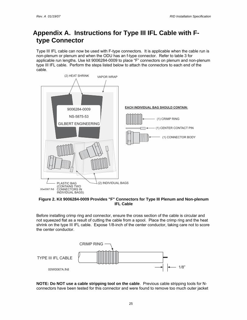
Appendix A. Instructions for Type III IFL Cable with F-type Connector Type III IFL cable can now be used with F-type connectors. It is applicable when the cable run is non-plenum or plenum and when the ODU has an f-type connector. Refer to table 3 for applicable run lengths. Use kit 9006284-0009 to place “F” connectors on plenum and non-plenum type III IFL cable. Perform the steps listed below to attach the connectors to each end of the cable.
�����������
�� ���������� ����� �������� ���������������������
������� ������� ��������
������������������
�����!"���
��"#��#"#$
����� ������������
���������������� ���������������
�%�����&�����
�%�������� ������'
�%����� ������ �� ���
Figure 2. Kit 9006284-0009 Provides "F" Connectors for Type III Plenum and Non-plenum IFL Cable
Before installing crimp ring and connector, ensure the cross section of the cable is circular and not squeezed flat as a result of cutting the cable from a spool. Place the crimp ring and the heat shrink on the type III IFL cable. Expose 1/8-inch of the center conductor, taking care not to score the center conductor.
������������
���&�����
%(�)
'�������*�����
NOTE: Do NOT use a cable stripping tool on the cable. Previous cable stripping tools for N-connectors have been tested for this connector and were found to remove too much outer jacket

Rev. A 01/19/07 RID Installation Specification
26
and were found to damage the braid. At this time, there is no cable stripping tool available for use with this cable and an f-connector.
Remove 3/8 inch of cable jacket. Do not cut ANY of the braid. If 15-25% of the braid is accidentally removed, the crimp connection will not work. If this occurs, the cable should be re-cut and the installation procedure repeated.
������������ $(�)
'�������*�����
Guide center conductor into center contact pin. Push until center contact pin is flush with dielectric. Crimp center contact pin using 0.100 hexagon crimping tool (the smallest crimp position on the HCT-231 tool is 0.100).
������������� ���&
*������ ������� ���
'�������*�����
Flare the braid slightly away from dielectric. Guide the center contact pin into connector body. Push connector body onto cable until a reasonable stop is felt without damaging the braid. Body should slide under braid without deforming flared shaped. If 15-25% of the braid is accidentally rolled under the connector body or bent back, the crimp connection will not work. If this occurs, the cable should be re-cut and the installation procedure repeated. Slide crimp ring over braid and into cavity in the back of the connector body.
�������������
'�������*�����
����
���� '
Apply 0.475 hexagon crimping tool two times to crimp ring (the largest crimp position on the HCT-231 tool is 0.475).
First apply the crimping tool to area 1 and second to area 2.
������������
'�������*�����
���&������%
���&�������

Rev. A 01/19/07 RID Installation Specification
27
Place the heat shrink tubing so that it is slightly behind the hex portion of the connector body and apply heat until it snugly grips the cable and the connector body.
������������
��� �������
'�������*�����
NOTE: When installing an F connector and a PES 5000 version 3, you may have an extra “F” plug to “N” jack adapter, p/n 9003769-0035, (figure 9) that you do not use. If so, save it for possible future use at another site.

Rev. A 01/19/07 RID Installation Specification
28
Appendix B. Letter of Authorization