rkjxw 8-directional stick switch (with encoder / center … · 2017-10-18 · rkjxw 8-directional...
TRANSCRIPT

459
Multi C
ontrolD
evicesS
witch
TypeV
ariableR
esistor Type
RKJXW 8-directional Stick Switch (with Encoder / Center-push Function)
Firm operating feel and high robustness ideal for integrated control of automotive equipment
■ Typical Specifications(Stick Switch)
Items RKJXW1 RKJXW2(Inner-shaft)
Rating(max.)(Resistive load) 10mA 5V DC
Contact resistance
8-direction 1kΩ max.Center-push
Travel8-direction 2±0.8mm 3±1mm
Center-push 1.4±0.5mm 1.4±0.5mm
Operating life8-direction Total with 8-direction 30,000 cycles
Center-push 30,000 cycles 100,000 cycles
■ Typical Specifications(Encoder)
Items RKJXW1 RKJXW2(Outer-shaft)
Rating(max.)(Resistive load) 10mA 5V DC
Operating life 30,000 cycles
Packing SpecificationsTray
Product No.Number of packages(pcs.) Export package
measurements(mm)1 case / Japan 1 case / export packing
RKJXW1014002 100 100 360×270×230
RKJXW2014001 50 50 420×370×225
Product Line
Product No. ShaftStick Switch
Encoders Minimum order unit (pcs.) Drawing
No.Maximum resolutionOperating force
Direction(N) Center Push(N) Detent torque Number of detent Number of pulse Japan Export
RKJXW1014002 18
2.5±1.53±1.5
30±20mN・m30 15
100 100 1
RKJXW2014001 2 3.5±2 40±16mN・m 50 50 2
RKJXW1
Dimensions Unit:mm
No. Photo Style
1
22.0
4
22.04
62°
21.25
2.7°
12.3°
42.2°
20.5 28
22.04
φ1.
5
27
φ36
1.5 13.1 513.425
4φ5 9.1
Pin 1
Connector no. :Molex 53261-1271
A A

460
Multi C
ontrolD
evicesV
ariableR
esistor TypeS
witch
Type
RKJXW
Dimensions Unit:mm
No. Photo Style
2
8-directional Stick Switch/SpecificationsCircuit Diagram/Output Relation Chart/Pin Configuration/8 Direction Codes Single-shaft Type(RKJXW1)
Circuit Diagram
Relative angle ofrib and hook of outer shaft
53
27.5
27.5
90°
3
5554
75.567
75.5
R30.5
61(M
ax v
alue
)
Ø 3.6
2-3.5
2-8
2-3
313.5
2-44
2-10
φ3.6
φ3.6φ3.6
70
MAX3
Connector:MOLEX 53261-1371Pin 1
LED: NICHIA NHSB046AT-R9-015T
φ31.4
45° 45°22.5°
90°
3.5
1.51.5
1.5
20°
Ø29
.4
5.95
4.1
4.6
8.5
3
0.8
Hook : 4 places
OUTER SHAFT
Rib : 4 places
1.68.3
151613
8.27.8
5
φ26.3
2-14.5 View A
Hook : 4 places
INNER SHAFT
3 36
3
17
9.7
Outer shaft
Inner shaft
A
Anode
Cathode
A Emitter (S1)
B Emitter (S2)
CollectorPhotointerrupter×2
Center-push
S1
S2
RotaryEncoder
a
b
c
d
S4
S8
S3
S7
S10
S6
S9B
C
A
S11
S5
8-directional switch array(S3 ー S10)
Switch matrix circuit: Output a~d
Switch matrix circuit: Input A~C
RKJXW2
8-directional Stick Switch (with Encoder / Center-push Function)

461
Multi C
ontrolD
evicesS
witch
TypeV
ariableR
esistor Type
RKJXW/8-directional Stick Switch (with Encoder / Center-push Function)
Dual-shaft Type(RKJXW2) Circuit Diagram
Circuit Diagram/Output Relation Chart/Pin Configuration/8 Direction Codes Single-shaft Type(RKJXW1)
Output Relation Chart
Switch No. S3 S4 S5 S6 S7 S8 S9 S10
A ON ON (ON) (ON)
B (ON) ON ON (ON)
C (ON) ON ON (ON)
D (ON) ON ON (ON)
E (ON) ON ON (ON)
F (ON) ON ON (ON)
G (ON) (ON) ON ON
H ON (ON) (ON) ON
""(ON)"" indicates that the switch is either On or Off at the time of the operation. Discern the direction of operation when two switches are On. Ignore any additional switches which may be switched On. Example: Operation in direction A 1st signal: S4 On > Standby 2nd signal: S3 On > Discern as direction A 3rd signal: S10 On > Ignore this signal (discern as direction A) 4th signal: S5 On > Ignore this signal (discern as direction A)
Pin Configuration Pin No.1 Photointerrupter Anode 2 Photointerrupter Cathode3 Output d(S11, S9, S5)4 Input A(S11)5 Output a(S4, S8)6 Output b(S3, S7)7 Input B(S4, S3, S10, S9)8 Input C(S8, S7, S6, S5)9 Output c(S10, S6)
10Photointerrupter A Emitter (S1)11Photointerrupter B Emitter (S2)12Photointerrupter Collector
8 Direction Codes
C
A
DE
F
G
H B
Dire
ctio
n
LED (1pcs)
Rotary Encoder
SW10
SW6
SW9
SW5
SW8
SW4
SW7
SW11
SW3
PIN 5
PIN 6
PIN 8
PIN 7
PIN 9
PIN 10
P 2
P 3
Q 1
Q 2
Q 3
Q 4
8-directional switch array(SW3 ー SW10)
Center push
PIN 12GND
PIN 13
PIN 11 LED+
LED_GND
ES_GND
PIN 4 P 1
PIN 3 EN_GND
PIN 2SW1 ENCODER 2
PIN 1SW2 ENCODER 1
Pin1
462
Multi C
ontrolD
evicesV
ariableR
esistor TypeS
witch
Type
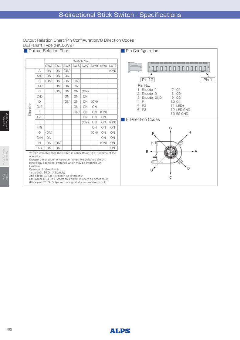
8-directional Stick Switch/Specifications
Output Relation Chart/Pin Configuration/8 Direction Codes Dual-shaft Type(RKJXW2)
Output Relation Chart
Switch No. SW3 SW4 SW5 SW6 SW7 SW8 SW9 SW10
A ON ON (ON) (ON)
A/B ON ON ON
B (ON) ON ON (ON)
B/C ON ON ON
C (ON) ON ON (ON)
C/D ON ON ON
D (ON) ON ON (ON)
D/E ON ON ON
E (ON) ON ON (ON)
E/F ON ON ON
F (ON) ON ON (ON)
F/G ON ON ON
G (ON) (ON) ON ON
G/H ON ON ON
H ON (ON) (ON) ON
H/A ON ON ON
""(ON)"" indicates that the switch is either On or Off at the time of the operation. Discern the direction of operation when two switches are On. Ignore any additional switches which may be switched On. Example: Operation in direction A 1st signal: S4 On > Standby 2nd signal: S3 On > Discern as direction A 3rd signal: S10 On > Ignore this signal (discern as direction A) 4th signal: S5 On > Ignore this signal (discern as direction A)
Pin Configuration
Pin No.1 Encoder 1 7 Q12 Encoder 2 8 Q23 Encoder GND 9 Q34 P1 10 Q45 P2 11 LED+6 P3 12 LED GND
13 ES GND
8 Direction Codes
A
G
B
C
D
E
F H
Pin 13 Pin 1
Dire
ctio
n

446
Multi C
ontrolD
evicesV
ariableR
esistor TypeS
witch
Type
Type Switch type
Series RKJXT1FRKJXM RKJXW
RKJXM1 RKJXM2 RKJXW1 RKJXW2
Photo
Dimensions(typical value)
(mm)
W17 11 19.5
36 61
D 48.5 75.5
H 10.5 6.6 5.45 26.5 17
Number of operating shafts Single-shaft Dual-shaft Single-shaft Dual-shaft
Shaft material Metal The inner shaft:MetalThe outer shaft:Resin Metal Resin
Directional resolution 4-direction 8-direction
Directional operating feeling(tactile feeling) With
Lever return mechanism With
Center-push switch With
Encoder With Without With
Operating temperature range −40℃ to +85℃
Operating life
Directional operation total with 4-direction50,000 cycles
total with 8-direction100,000 cycles
30,000 cycles for each direction
Center-push 30,000 cycles 100,000 cycles
Encoder 15,000 cycles ー 15,000 cycles 30,000 cycles
Automotive use ● ● ● ● ●
Life cycle (availability)
Rating(max.)(Resistive load) 10mA 5V DC
Electrical performance
Output voltage ー ー ー ー ー
Encoder resolution 15pulses/360° ー 15pulses/360°
Insulation resistance 100MΩ min. 250V DC 10MΩ min. 50V DC
Voltage proof 250V AC for 1min. 360V AC for 2s 60V AC for 2s
Mechanical performance
Directional operating force
40±25mN・m
Direction A, B, C, D30±20mN・m
2.5±1.5N 3.5±2NDirection AB, BC, CD, DA
25±20mN・m
Push operating force 5±2N 3±1.5N
Encoder detent torque 15±8mN・m ー 12±8mN・m 30±20mN・m 40±16mN・m
Terminal strength 5N for 1min. ー ー
Actuatorstrength
Push / pull directions 100N (Push/Pull) 100N(Push), 50N(Pull) 100N (Push)Operating direction 0.4N・m 0.3N・m 50N 100N
Environmental performance
Cold −40℃ 500h
Dry heat 85℃ 500h
Damp heat 60℃, 90 to 95%RH 500h 40℃, 90 to 95%RH 500h
Page 455 457 459
Switch Type Multi Control Devices Soldering Conditions ・・・・・・・・・・・・・・・・・・・・・・・・・・・・・・・・・・・・・472Switch Type Multi Control Devices Cautions ・・・・・・・・・・・・・・・・・・・・・・・・・・・・・・・・・・・・・・・・・・・473
Note
● Indicates applicability to all products in the series.
List of VarietiesMulti Control Devices