rkkl-b package gas electric unit
TRANSCRIPT
RKKL-B Standard Efficiency• Nominal Sizes 15 & 20 Tons [52.8 & 70.3 kW]
With optional hailguard shown
www.SureComfort.com
MODEL: RKKL-BPackage Gas Electric Unit
FORM NO. RSC-859
Sure Comfort® RKKL-B Package Gas Electric Unit
Sure Comfort® RKKL-B Package Gas Electric Unit
2 www.SureComfort.com
Table of ContentsUnit Features & Benefits ..............................................................................3-7
Model Number Identification ............................................................................8
Options..........................................................................................................9
Selection Procedure ......................................................................................10
General Data
RKKL-B ..............................................................................................11-17
General Data Notes ......................................................................................18
Gross Systems Performance Data
RKKL-B ....................................................................................................19
Indoor Airflow Performance
RKKL-B ..............................................................................................20-21
Electrical Data
RKKL-B ..............................................................................................22-23
Dimensional Data ....................................................................................24-26
Slab Installation ............................................................................................27
Accessories ............................................................................................28-39
Mechanical Specifications ........................................................................40-45
Wiring Diagrams ......................................................................................46-49
Limited Warranty ..........................................................................................50

Sure Comfort® RKKL-B Package Gas Electric Unit
3www.SureComfort.com
• R-410A HFC refrigerant.• Complete factory charged, wired and run tested.• Scroll compressors with internal line break overload and
high-pressure protection.• Two independent refrigerant circuits each with a scroll
compressor provide two stage cooling operation.• Convertible airflow – vertical downflow or horizontal sideflow.• Capillary tube refrigerant metering system on each circuit.• High Pressure and Low Pressure/Loss of charge protection
standard on all models.• Solid Core liquid line filter drier on each circuit.• Single slab, single pass designed evaporator and condenser
coils facilitate easy cleaning for maintaining high efficiencies.• Cooling operation up to 125 degree F ambient.• Foil faced insulation encapsulated throughout entire unit
minimizes airborne fibers from the air stream.• Hinged major access door with heavy-duty gasketing.• Slide Out Indoor fan assembly for added service
convenience.• Powder Paint Finish meets ASTMB117 steel coated on each
side for maximum protection. G90 galvanized.• Base pan with drawn supply and return opening for superior
water management.
• Forkable base rails for easy handling and lifting.• Single point electrical connections.• Internally sloped slide out condensate pan conforms to
ASHRAE 62 standards.• High performance belt drive motor with variable pitch pulleys
and quick adjust belt system.• Permanently lubricated evaporator, condenser and gas heat
inducer motors.• Condenser motors are internally protected, totally enclosed
with shaft down design.• 2 inch filter standard with slide out design.• Two stage gas valve, direct spark ignition, and induced draft
for efficiency and reliability.• Tubular heat exchange for long life and induced draft for
efficiency and reliability.• Solid state furnace control with on board diagnostics.• 24 volt control system with resettable circuit breakers.• Colored and labeled wiring.• Copper tube/Aluminum Fin indoor coil.• Aluminum MicroChannel outdoor coil(s).
RKKL-B STANDARD FEATURES INCLUDE:
Sure Comfort Package Gas Electric Unit Features:

Sure Comfort® RKKL-B Package Gas Electric Unit
4 www.SureComfort.com
Sure Comfort Package equipment is designed from the groundup with the latest features and benefits required to compete intoday’s market. The clean design stands alone in the industryand is a testament to the quality, reliability, ease of installationand serviceability that goes into each unit. Outwardly, the largeSure Comfort label ( ) identifies the brand to the customer.
The sheet-metal cabinet ( ) uses nothing less than 20-gaugematerial for structural components with an underlying coat ofG90. To ensure the leak-proof integrity of these units, the designutilizes a top with a 1/8" drip lip ( ), gasket-protected panelsand screws. The (optional) hail guard protects the coil from haildamage ( ). Every Sure Comfort package unit uses the tough-est finish in the industry, using electro deposition baked-onenamel tested to withstand a rigorous 1000-hour salt spray test,per ASTM B117.
Anything built to last must start with the right foundation. In thiscase, the foundation is 14-gauge, commercial-grade, full-perimeter base rails ( ), which integrate fork slots and riggingholes to save set-up time on the job site. The base pan isstamped, which forms a 1-1/8" flange around the supply andreturn opening and has eliminated the worry of water enteringthe conditioned space ( ). The drainpan ( ) is made of mater-ial that resists the growth of harmful bacteria and is sloped forthe latest IAQ benefits. Furthermore, the drainpan slides out foreasy cleaning. The insulation has been placed on the undersideof the basepan, removing areas that would allow for potentialmoisture accumulation, which can facilitate growth of harmfulbacteria. All insulation is secured with both adhesive andmechanical fasteners, and all edges are hidden.
During development, each unit was tested to U.L. 1995, ANSI21.47, AHRI 340-360 and other Sure Comfort-required reliabilitytests. Sure Comfort adheres to stringent IS0 9002 quality proce-dures, and each unit bears the U.L. and AHRI certification labelslocated on the unit nameplate ( ). Contractors can restassured that when a Sure Comfort package unit arrives at thejob, it is ready to go with a factory charge and quality checks.
Access to all major compartments is from the front of the unit,including the filter and electrical compartment, blower compart-ment, furnace section, and outdoor section. Each panel is per-manently embossed with the compartment name (control/filteraccess, blower access and furnace access).
Electrical and filter compartment access is through a large,hinged-access panel. On the outside of the panel is the unitnameplate, which contains the model and serial number, electri-cal data and other important unit information.
The unit charging chart is located on the inside of the electricaland filter compartment door. Electrical wiring diagrams arefound on the control box cover, which allows contractors tomove them to more readable locations. To the right of the control box the modeland serial number can befound. Having this infor-mation on the inside willassure model identifica-tion for the life of the product. The productionline quality test assurancelabel is also placed in thislocation ( ). The two-inch throwaway filters ( ) are easily removed on a tracked system foreasy replacement.
76
5
2
1
4
8
9
10
3
6
6
2
1
4
5
9
10
7
3
8
Sure Comfort® RKKL-B Package Gas Electric Unit
5www.SureComfort.com
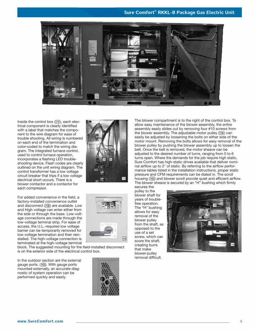
Inside the control box ( ), each elec-trical component is clearly identifiedwith a label that matches the compo-nent to the wire diagram for ease oftrouble shooting. All wiring is numberedon each end of the termination andcolor-coded to match the wiring dia-gram. The integrated furnace control,used to control furnace operation,incorporates a flashing LED trouble -shooting device. Flash codes are clearlyoutlined on the unit wiring diagram. Thecontrol transformer has a low voltagecircuit breaker that trips if a low voltageelectrical short occurs. There is ablower contactor and a contactor foreach compressor.
For added convenience in the field, afactory-installed convenience outletand disconnect ( ) are available. Lowand High voltage can enter either fromthe side or through the base. Low-volt-age connections are made through thelow-voltage terminal strip. For ease ofaccess, the U.L.-required low voltagebarrier can be temporarily removed forlow-voltage termination and then rein-stalled. The high-voltage connection isterminated at the high-voltage terminalblock. The suggested mounting for the field-installed disconnectis on the exterior side of the electrical control box.
In the outdoor section are the externalgauge ports. ( ). With gauge portsmounted externally, an accurate diag-nostic of system operation can beperformed quickly and easily.
The blower compartment is to the right of the control box. Toallow easy maintenance of the blower assembly, the entireassembly easily slides out by removing four #10 screws fromthe blower assembly. The adjustable motor pulley ( ) caneasily be adjusted by loosening the bolts on either side of themotor mount. Removing the bolts allows for easy removal of theblower pulley by pushing the blower assembly up to loosen thebelt. Once the belt is removed, the motor sheave can beadjusted to the desired number of turns, ranging from 0 to 6turns open. Where the demands for the job require high static,Sure Comfort has high-static drives available that deliver nomi-nal airflow up to 2" of static. By referring to the airflow perfor-mance tables listed in the installation instructions, proper staticpressure and CFM requirements can be dialed in. The scrollhousing ( ) and blower scroll provide quiet and efficient airflow.The blower sheave is secured by an “H” bushing which firmlysecures thepulley to theblower shaft foryears of trouble-free operation.The “H” bushingallows for easyremoval of theblower pulleyfrom the shaft, asopposed to theuse of a setscrew, which canscore the shaft,creating burrsthat makeblower-pulleyremoval difficult.
15
14
13
12
11
10
13
11
12
14
15

6 www.SureComfort.com
Also inside the blower compartment are theoptional low-ambient controls ( ). The low-ambient controls allow for operation of the com-pressor down to 0 degrees ambient temperatureby cycling the outdoor fans on high pressure.Use of polarized plugs and schrader fittingsallow for easy field or factory installation.
Inside the blower compartment the interlacedevaporator can also be viewed. The evaporatoruses enhanced fin technology for maximum heattransfer. The capillary tube metering device assures even distrib-ution of refrigerant throughout the evaporator.
Wiring throughout the unitis neatly bundled androuted. Where wire har-nesses go through thecondenser bulkhead orblower deck, a moldedwire harness assembly ( )provides an air-tight andwater-tight seal, and pro-vides strain relief. Care isalso taken to tuck rawedges of insulation behind sheet metal to improve indoor airquality.
The furnace compartment contains the latest furnace technologyon the market. The draft inducers ( ) draw the flame from theSure Comfort exclusive in-shot burners ( ) into the aluminizedtubular heat exchanger ( ) for clean, efficient gas heat. Stain-less steel heat exchangers can be factory installed for thoseapplications that have high fresh-air requirements, or applica-tions in corrosive environments. Each furnace is equipment witha two-stage gas valve ( ), which provides two stages of gasheat input. The first stage operates at 50% of the second stage(full fire). 81% steady state efficiency is maintained on both firstand second stage by staging the multiple inducers to optimizethe combustion airflow and maintain a near stoichiometric burnat each stage.
The direct spark igniter ( ) assures reliable ignition in the most adverse conditions. This is coupled with remote flame sense ( )to assure that the flame has carried across the entire length ofthe burner assembly. Gas supply can be routed from the side orup through the base.
Each furnace has the following safety devices to assure consis-tent and reliable operation after ignition: • Pressures switches ( ) to assure adequate combustion air-
flow before ignition. • Rollout switches ( ) to assure no obstruction or cracks in the
heat exchanger.• A limit device that protects the furnace from over-temperature
problems.
25
24
23
22
21
20
19
18
16
17
18
25
25
24
23
25
19
20
19
17
24
18
18
25
22
21
18
25
24
16
Sure Comfort® RKKL-B Package Gas Electric Unit
Sure Comfort® RKKL-B Package Gas Electric Unit
7www.SureComfort.com
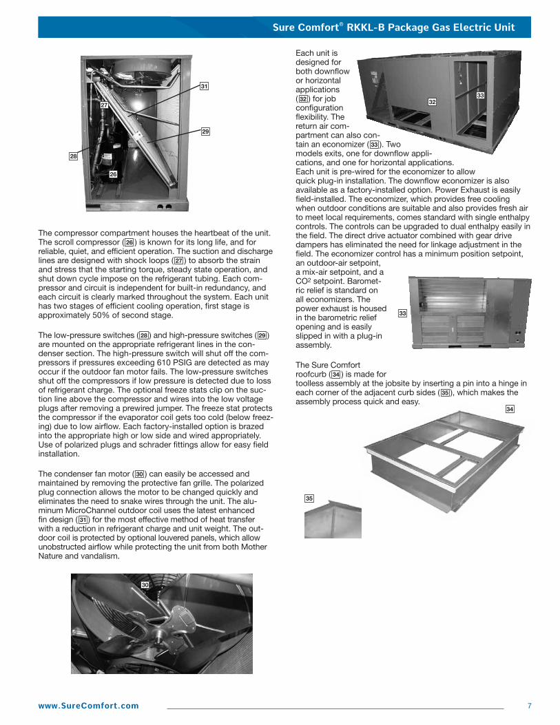
The compressor compartment houses the heartbeat of the unit.The scroll compressor ( ) is known for its long life, and forreliable, quiet, and efficient operation. The suction and dischargelines are designed with shock loops ( ) to absorb the strainand stress that the starting torque, steady state operation, andshut down cycle impose on the refrigerant tubing. Each com-pressor and circuit is independent for built-in redundancy, andeach circuit is clearly marked throughout the system. Each unithas two stages of efficient cooling operation, first stage isapproximately 50% of second stage.
The low-pressure switches ( ) and high-pressure switches ( )are mounted on the appropriate refrigerant lines in the con -denser section. The high-pressure switch will shut off the com-pressors if pressures exceeding 610 PSIG are detected as mayoccur if the outdoor fan motor fails. The low-pressure switchesshut off the compressors if low pressure is detected due to lossof refrigerant charge. The optional freeze stats clip on the suc-tion line above the compressor and wires into the low voltageplugs after removing a prewired jumper. The freeze stat protectsthe compressor if the evaporator coil gets too cold (below freez-ing) due to low airflow. Each factory-installed option is brazedinto the appropriate high or low side and wired appropriately.Use of polarized plugs and schrader fittings allow for easy fieldinstallation.
The condenser fan motor ( ) can easily be accessed and maintained by removing the protective fan grille. The polarizedplug connection allows the motor to be changed quickly andeliminates the need to snake wires through the unit. The alu-minum MicroChannel outdoor coil uses the latest enhanced fin design ( ) for the most effective method of heat transfer with a reduction in refrigerant charge and unit weight. The out-door coil is protected by optional louvered panels, which allowunobstructed airflow while protecting the unit from both MotherNature and vandalism.
Each unit isdesigned forboth downflowor horizontalapplications( ) for jobconfigurationflexibility. Thereturn air com-partment can also con-tain an economizer ( ). Twomodels exits, one for downflow appli-cations, and one for horizontal applications.Each unit is pre-wired for the economizer to allowquick plug-in installation. The downflow economizer is alsoavailable as a factory-installed option. Power Exhaust is easilyfield-installed. The economizer, which provides free coolingwhen outdoor conditions are suitable and also provides fresh airto meet local requirements, comes standard with single enthalpycontrols. The controls can be upgraded to dual enthalpy easily inthe field. The direct drive actuator combined with gear drivedampers has eliminated the need for linkage adjustment in thefield. The economizer control has a minimum position setpoint,an outdoor-air setpoint,a mix-air setpoint, and aCO2 setpoint. Baromet-ric relief is standard onall economizers. Thepower exhaust is housedin the barometric reliefopening and is easilyslipped in with a plug-inassembly.
The Sure Comfortroofcurb ( ) is made fortoolless assembly at the jobsite by inserting a pin into a hinge ineach corner of the adjacent curb sides ( ), which makes theassembly process quick and easy.
2928
30
35
34
33
32
27
26
31
26
34
33
333227
35
29
30
28
31

Sure Comfort® RKKL-B Package Gas Electric Unit
8 www.SureComfort.com
R K K L — B 180 C L 25 E X X X Economizer Option (See Next Page) Factory Installed Options (See Next Page) Ignition System E = Electric Heating Capacity (MBH) 25 = 250,000 [73.27] 15 Ton 30 = 300,000 [87.92] 20/25 Ton 35 = 350,000 [102.57] 15 Ton 40 = 400,000 [117.23] 20/25 Ton
Drive Package L = Belt Drive M= Belt Drive—High Static N = Belt Drive—Field Installed
Electrical Designation C = 208-230 V, 3 PH, 60 Hz D = 460 V, 3 PH, 60 Hz Y = 575 V, 3 PH, 60 Hz
Cooling Capacity (BTUH) [kW] 180 = 180,000 [52.75] 240 = 240,000 [70.34]
Future Technical Variations
Design Series L = R410A Refrigerant Efficiency Designation K = Standard Efficiency
Product Classification K = Rooftop—Commercial Tradebrand R = Sure Comfort Packaged Gas/Electric
[ ] Designates Metric Conversions
Sure Comfort® RKKL-B Package Gas Electric Unit
9www.SureComfort.com
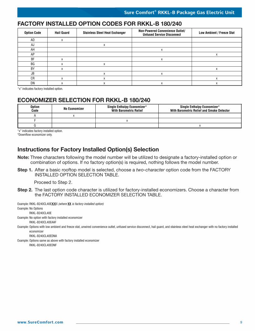
Option Code Hail Guard Stainless Steel Heat Exchanger Non-Powered Convenience Outlet/Unfused Service Disconnect Low Ambient / Freeze Stat
AD xAJ xAH xAP xBF x xBG x xBY x xJB x xCR x x xDN x x x x
FACTORY INSTALLED OPTION CODES FOR RKKL-B 180/240
“x” indicates factory installed option.
ECONOMIZER SELECTION FOR RKKL-B 180/240
Example: RKKL-B240CL40EXXX (where XX is factory installed option)Example: No Options
RKKL-B240CL40EExample: No option with factory installed economizer
RKKL-B240CL40EAAF Example: Options with low ambient and freeze stat, unwired convenience outlet, unfused service disconnect, hail guard, and stainless steel heat exchanger with no factory installed
economizerRKKL-B240CL40EDNA
Example: Options same as above with factory installed economizerRKKL-B240CL40EDNF
OptionCode No Economizer Single Enthalpy Economizer*
With Barometric ReliefA xF x
Single Enthalpy Economizer*With Barometric Relief and Smoke Detector
G x
“x” indicates factory installed option.*Downflow economizer only.
Instructions for Factory Installed Option(s) SelectionNote: Three characters following the model number will be utilized to designate a factory-installed option or
combination of options. If no factory option(s) is required, nothing follows the model number.
Step 1. After a basic rooftop model is selected, choose a two-character option code from the FACTORYINSTALLED OPTION SELECTION TABLE.
Proceed to Step 2.
Step 2. The last option code character is utilized for factory-installed economizers. Choose a character fromthe FACTORY INSTALLED ECONOMIZER SELECTION TABLE.

Sure Comfort® RKKL-B Package Gas Electric Unit
10 www.SureComfort.com
To select an RKKL-B Cooling and Heating unit to meet a jobrequire ment, follow this procedure, with example, using datasupplied in this specification sheet.
1. DETERMINE COOLING AND HEATING REQUIREMENTSAND SPECIFIC OPERATING CONDITIONS FROM PLANSAND SPECS.
Example: Voltage— 208/240V—3 Phase—60 HzTotal Cooling Capacity— 205,000 BTUH [60.0 kW]Sensible Cooling Capacity— 155,000 BTUH [45.4 kW]Heating Capacity— 235,000 BTUH [68.8 kW]*Condenser Entering Air— 95°F [35.0°C] DB*Evaporator Mixed Air Entering—65°F [18.3°C] WB; 78°F [25.6°C] DB*Indoor Air Flow (vertical)— 7200 CFM [3398 L/s]*External Static Pressure— .70 in. WG [.17 kPa]
2. SELECT UNIT TO MEET COOLING REQUIREMENTS.
Since total cooling is within the range of a nominal 20 ton[70.3 kW] unit, enter cooling performance table at 95°F [35.0 °C] DB condenser inlet air. Interpolate between 63°F[17.2 °C] WB and 67°F [19.4 °C] WB to determine total andsensible capacity and power input for 65°F [18.3 °C] WBevaporator inlet air at 7825 CFM [3692 L/s] indoor air flow(table basis):
Total Cooling Capacity = 245,500 BTUH [71.88 kW]Sensible Cooling Capacity = 201,150 BTUH [58.90 kW]Power Input (Compressor and Cond. Fans) = 19,750 watts
Use formula in note (1) to determine sensible capacity at 78°F[25.6 °C] DB evaporator entering air:
201,150 + (1.10 x 7,200 x (1 - 0.11) x (78 - 80))Sensible Cooling Capacity = 187,052 BTUH [54.77 kW]
3. CORRECT CAPACITIES OF STEP 2 FOR ACTUALAIR FLOW.
Select factors from airflow correction table at 7200 CFM [3398 L/s] and apply to data obtained in step 2 to obtaingross capacity:
Total Capacity = 245,500 x 0.99 = 243,045 BTUH [71.17 kW]Sensible Capacity = 187,052 x 0.95 = 177,699 BTUH [52.03 kW]Power Input = 19,750 x 0.99 = 19,553 Watts
These are Gross Capacities, not corrected for blower motorheat or power.
4. DETERMINE BLOWER SPEED AND WATTS TOMEET SYSTEM DESIGN.
Enter Indoor Blower performance table at 7200 CFM [3398 L/s]. Total ESP (external static pressure) per the spec of 0.70 in. WG [.17 kPa] includes the system duct and grilles.Add from the table “Component Air Resistance”, 0.01 in. WG[.00 kPa]for wet coil, 0.08 in. WG [.02 kPa] for downflow airflow, for a total selection static pressure of 0.79 (0.8) in. WG[.20 kPa], and determine:
RPM = 741WATTS = 2,895DRIVE = L (standard 5 H.P. motor)
5. CALCULATE INDOOR BLOWER BTUH HEAT EFFECTFROM MOTOR WATTS, STEP 4.
2,895 x 3.412 = 9,878 BTUH [2.89 kW]
6. CALCULATE NET COOLING CAPACITIES, EQUAL TOGROSS CAPACITY, STEP 3, MINUS INDOOR BLOWERMOTOR HEAT.
Net Total Capacity = 243,045-9,878 =233,167 BTUH [68.27 kW]
Net Sensible Capacity = 177,699 - 9,878 =167,821 BTUH [49.14 kW]
7. CALCULATE UNIT INPUT AND JOB EER.
Total Power Input = 19,553 (step 3) + 2,895(step 4) = 22,448 Watts
EER = Net Total BTUH [kW] (step 6)= 233,167 = 10.39 Power Input, Watts (above) 22,448
8. SELECT UNIT HEATING CAPACITY.
From Physical Data Table read that gas heating output (input rating x efficiency) is:
Heating Capacity = 243,000 BTUH [71.2 kW]
9. CHOOSE MODEL RKKL-B240CL30E
*NOTE: These operating conditions are typical of a commercial applica-tion in a 95°F/79°F [35°C/26°C] design area with indoor designof 76°F [24°C] DB and 50% RH and 10% ventilation air, withthe unit roof mounted and centered on the zone it conditions by ducts.
[ ] Designates Metric Conversions

Sure Comfort® RKKL-B Package Gas Electric Unit
11www.SureComfort.com
Model RKKL- B180CL25E B180CL35E B180CM25E B180CM35E
Cooling Performance1 CONTINUEDGross Cooling Capacity Btu [kW] 174,000 [50.98] 174,000 [50.98] 174,000 [50.98] 174,000 [50.98]
EER/SEER2 10.9/NA 10.9/NA 10.9/NA 10.9/NA
Nominal CFM/AHRI Rated CFM [L/s] 6000/5500 [2831/2595] 6000/5500 [2831/2595] 6000/5500 [2831/2595] 6000/5500 [2831/2595]
AHRI Net Cooling Capacity Btu [kW] 170,000 [49.81] 170,000 [49.81] 170,000 [49.81] 170,000 [49.81]
Net Sensible Capacity Btu [kW] 125,400 [36.74] 125,400 [36.74] 125,400 [36.74] 125,400 [36.74]
Net Latent Capacity Btu [kW] 44,600 [13.07] 44,600 [13.07] 44,600 [13.07] 44,600 [13.07]
IEER3 11.1 11.1 11.1 11.1
Net System Power kW 15.6 15.6 15.6 15.6
Heating Performance (Gas)4
Heating Input Btu [kW] (1st Stage / 2nd Stage) 125,000/250,000 [36.62/73.25] 175,000/350,000 [51.27/102.55] 125,000/250,000 [36.62/73.25] 175,000/350,000 [51.27/102.55]
Heating Output Btu [kW] (1st Stage / 2nd Stage) 101,500/203,000 [29.74/59.48] 142,000/284,000 [41.61/83.21] 101,500/203,000 [29.74/59.48] 142,000/284,000 [41.61/83.21]
Temperature Rise Range °F [°C](1st / 2nd Stage)
15-45 [8.3-25] /15-45 [8.3-25]
30-60 [16.7-33.3] / 30-60 [16.7-33.3]
15-45 [8.3-25] / 15-45 [8.3-25]
30-60 [16.7-33.3] / 30-60 [16.7-33.3]
Steady State Efficiency (%) 81 81 81 81
No. Burners 10 14 10 14
No. Stages 2 2 2 2
Gas Connection Pipe Size in. [mm] 0.75 [19] 0.75 [19] 0.75 [19] 0.75 [19]
CompressorNo./Type 2/Scroll 2/Scroll 2/Scroll 2/Scroll
Outdoor Sound Rating (dB)5 91 91 91 91
Outdoor Coil—Fin Type Louvered Louvered Louvered Louvered
Tube Type MicroChannel MicroChannel MicroChannel MicroChannel
MicroChannel Depth in. [mm] 1 [25.4] 1 [25.4] 1 [25.4] 1 [25.4]
Face Area sq. ft. [sq. m] 27.46 [2.55] 27.46 [2.55] 27.46 [2.55] 27.46 [2.55]
Rows / FPI [FPcm] 1 / 23 [9] 1 / 23 [9] 1 / 23 [9] 1 / 23 [9]
Indoor Coil—Fin Type Louvered Louvered Louvered Louvered
Tube Type Rifled Rifled Rifled Rifled
Tube Size in. [mm] 0.375 [9.5] 0.375 [9.5] 0.375 [9.5] 0.375 [9.5]
Face Area sq. ft. [sq. m] 26.67 [2.48] 26.67 [2.48] 26.67 [2.48] 26.67 [2.48]
Rows / FPI [FPcm] 2 / 18 [7] 2 / 18 [7] 2 / 18 [7] 2 / 18 [7]
Refrigerant Control Capillary Tubes Capillary Tubes Capillary Tubes Capillary Tubes
Drain Connection No./Size in. [mm] 1/1 [25.4] 1/1 [25.4] 1/1 [25.4] 1/1 [25.4]
Outdoor Fan—Type Propeller Propeller Propeller Propeller
No. Used/Diameter in. [mm] 3/24 [609.6] 3/24 [609.6] 3/24 [609.6] 3/24 [609.6]
Drive Type/No. Speeds Direct/1 Direct/1 Direct/1 Direct/1
CFM [L/s] 10000 [4719] 10000 [4719] 10000 [4719] 10000 [4719]
No. Motors/HP 3 at 1/2 HP 3 at 1/2 HP 3 at 1/2 HP 3 at 1/2 HP
Motor RPM 1075 1075 1075 1075
Indoor Fan—Type FC Centrifugal FC Centrifugal FC Centrifugal FC Centrifugal
No. Used/Diameter in. [mm] 2/18x9 [457x229] 2/18x9 [457x229] 2/18x9 [457x229] 2/18x9 [457x229]
Drive Type/No. Speeds Belt/Variable Belt/Variable Belt/Variable Belt/Variable
No. Motors 1 1 1 1
Motor HP 3 3 5 5
Motor RPM 1725 1725 1725 1725
Motor Frame Size 56 56 184 184
Filter—Type Disposable Disposable Disposable Disposable
Furnished Yes Yes Yes Yes
(NO.) Size Recommended in. [mm x mm x mm] (8)2x25x20 [51x635x508] (8)2x25x20 [51x635x508] (8)2x25x20 [51x635x508] (8)2x25x20 [51x635x508]
Refrigerant Charge Oz. [g] 115/119 [3260/3374] 115/119 [3260/3374] 115/119 [3260/3374] 115/119 [3260/3374]
WeightsNet Weight lbs. [kg] 1799 [816] 1812 [822] 1828 [829] 1841 [835]
Ship Weight lbs. [kg] 1926 [874] 1939 [880] 1955 [887] 1968 [893]
NOM. SIZES 15 & 20 TONS [52.8 & 70.3 kW]
See Page 18 for Notes. [ ] Designates Metric Conversions

Sure Comfort® RKKL-B Package Gas Electric Unit
12 www.SureComfort.com
Model RKKL- B180DL25E B180DL35E B180DM25E B180DM35E
Cooling Performance1 CONTINUEDGross Cooling Capacity Btu [kW] 174,000 [50.98] 174,000 [50.98] 174,000 [50.98] 174,000 [50.98]
EER/SEER2 10.9/NA 10.9/NA 10.9/NA 10.9/NA
Nominal CFM/AHRI Rated CFM [L/s] 6000/5500 [2831/2595] 6000/5500 [2831/2595] 6000/5500 [2831/2595] 6000/5500 [2831/2595]
AHRI Net Cooling Capacity Btu [kW] 170,000 [49.81] 170,000 [49.81] 170,000 [49.81] 170,000 [49.81]
Net Sensible Capacity Btu [kW] 125,400 [36.74] 125,400 [36.74] 125,400 [36.74] 125,400 [36.74]
Net Latent Capacity Btu [kW] 44,600 [13.07] 44,600 [13.07] 44,600 [13.07] 44,600 [13.07]
IEER3 11.1 11.1 11.1 11.1
Net System Power kW 15.6 15.6 15.6 15.6
Heating Performance (Gas)4
Heating Input Btu [kW] (1st Stage / 2nd Stage) 125,000/250,000 [36.62/73.25] 175,000/350,000 [51.27/102.55] 125,000/250,000 [36.62/73.25] 175,000/350,000 [51.27/102.55]
Heating Output Btu [kW] (1st Stage / 2nd Stage) 101,500/203,000 [29.74/59.48] 142,000/284,000 [41.61/83.21] 101,500/203,000 [29.74/59.48] 142,000/284,000 [41.61/83.21]
Temperature Rise Range °F [°C](1st / 2nd Stage)
15-45 [8.3-25] / 15-45 [8.3-25]
30-60 [16.7-33.3] /30-60 [16.7-33.3]
15-45 [8.3-25] /15-45 [8.3-25]
30-60 [16.7-33.3] /30-60 [16.7-33.3]
Steady State Efficiency (%) 81 81 81 81
No. Burners 10 14 10 14
No. Stages 2 2 2 2
Gas Connection Pipe Size in. [mm] 0.75 [19] 0.75 [19] 0.75 [19] 0.75 [19]
CompressorNo./Type 2/Scroll 2/Scroll 2/Scroll 2/Scroll
Outdoor Sound Rating (dB)5 91 91 91 91
Outdoor Coil—Fin Type Louvered Louvered Louvered Louvered
Tube Type MicroChannel MicroChannel MicroChannel MicroChannel
MicroChannel Depth in. [mm] 1 [25.4] 1 [25.4] 1 [25.4] 1 [25.4]
Face Area sq. ft. [sq. m] 27.46 [2.55] 27.46 [2.55] 27.46 [2.55] 27.46 [2.55]
Rows / FPI [FPcm] 1 / 23 [9] 1 / 23 [9] 1 / 23 [9] 1 / 23 [9]
Indoor Coil—Fin Type Louvered Louvered Louvered Louvered
Tube Type Rifled Rifled Rifled Rifled
Tube Size in. [mm] 0.375 [9.5] 0.375 [9.5] 0.375 [9.5] 0.375 [9.5]
Face Area sq. ft. [sq. m] 26.67 [2.48] 26.67 [2.48] 26.67 [2.48] 26.67 [2.48]
Rows / FPI [FPcm] 2 / 18 [7] 2 / 18 [7] 2 / 18 [7] 2 / 18 [7]
Refrigerant Control Capillary Tubes Capillary Tubes Capillary Tubes Capillary Tubes
Drain Connection No./Size in. [mm] 1/1 [25.4] 1/1 [25.4] 1/1 [25.4] 1/1 [25.4]
Outdoor Fan—Type Propeller Propeller Propeller Propeller
No. Used/Diameter in. [mm] 3/24 [609.6] 3/24 [609.6] 3/24 [609.6] 3/24 [609.6]
Drive Type/No. Speeds Direct/1 Direct/1 Direct/1 Direct/1
CFM [L/s] 10000 [4719] 10000 [4719] 10000 [4719] 10000 [4719]
No. Motors/HP 3 at 1/2 HP 3 at 1/2 HP 3 at 1/2 HP 3 at 1/2 HP
Motor RPM 1075 1075 1075 1075
Indoor Fan—Type FC Centrifugal FC Centrifugal FC Centrifugal FC Centrifugal
No. Used/Diameter in. [mm] 2/18x9 [457x229] 2/18x9 [457x229] 2/18x9 [457x229] 2/18x9 [457x229]
Drive Type/No. Speeds Belt/Variable Belt/Variable Belt/Variable Belt/Variable
No. Motors 1 1 1 1
Motor HP 3 3 5 5
Motor RPM 1725 1725 1725 1725
Motor Frame Size 56 56 184 184
Filter—Type Disposable Disposable Disposable Disposable
Furnished Yes Yes Yes Yes
(NO.) Size Recommended in. [mm x mm x mm] (8)2x25x20 [51x635x508] (8)2x25x20 [51x635x508] (8)2x25x20 [51x635x508] (8)2x25x20 [51x635x508]
Refrigerant Charge Oz. [g] 115/119 [3260/3374] 115/119 [3260/3374] 115/119 [3260/3374] 115/119 [3260/3374]
WeightsNet Weight lbs. [kg] 1799 [816] 1812 [882] 1828 [829] 1841 [835]
Ship Weight lbs. [kg] 1926 [874] 1939 [880] 1955 [887] 1968 [893]
NOM. SIZES 15 & 20 TONS [52.8 & 70.3 kW]
See Page 18 for Notes. [ ] Designates Metric Conversions

Sure Comfort® RKKL-B Package Gas Electric Unit
13www.SureComfort.com
Model RKKL- B180YL35E B180YM35E B240CL30E B240CL40E
Cooling Performance1 CONTINUEDGross Cooling Capacity Btu [kW] 174,000 [50.98] 174,000 [50.98] 250,000 [73.25] 250,000 [73.25]
EER/SEER2 10.9/NA 10.9/NA 10.5/NA 10.5/NA
Nominal CFM/AHRI Rated CFM [L/s] 6000/5500 [2831/2595] 6000/5500 [2831/2595] 8000/7825 [3775/3693] 8000/7825 [3775/3693]
AHRI Net Cooling Capacity Btu [kW] 170,000 [49.81] 170,000 [49.81] 240,000 [70.32] 240,000 [70.32]
Net Sensible Capacity Btu [kW] 125,400 [36.74] 125,400 [36.74] 175,000 [51.27] 175,000 [51.27]
Net Latent Capacity Btu [kW] 44,600 [13.07] 44,600 [13.07] 65,000 [19.04] 65,000 [19.04]
IEER3 11.1 11.1 10.5 10.5
Net System Power kW 15.6 15.6 22.88 22.88
Heating Performance (Gas)4
Heating Input Btu [kW] (1st Stage / 2nd Stage) 175,000/350,000 [51.27/102.55] 175,000/350,000 [51.27/102.55] 150,000/300,000 [43.95/87.9] 200,000/400,000 [58.6/117.2]
Heating Output Btu [kW] (1st Stage / 2nd Stage) 142,000/284,000 [41.61/83.21] 142,000/284,000 [41.61/83.21] 121,500/243,000 [35.6/71.2] 162,000/324,000 [47.47/94.93]
Temperature Rise Range °F [°C](1st / 2nd Stage)
30-60 [16.7-33.3] /30-60 [16.7-33.3]
30-60 [16.7-33.3] /30-60 [16.7-33.3]
15-45 [8.3-25] /15-45 [8.3-25]
25-55 [13.9-30.6] /25-55 [13.9-30.6]
Steady State Efficiency (%) 81 81 81 81
No. Burners 14 14 12 14
No. Stages 2 2 2 2
Gas Connection Pipe Size in. [mm] 0.75 [19] 0.75 [19] 0.75 [19] 0.75 [19]
CompressorNo./Type 2/Scroll 2/Scroll 2/Scroll 2/Scroll
Outdoor Sound Rating (dB)5 91 91 91 91
Outdoor Coil—Fin Type Louvered Louvered Louvered Louvered
Tube Type MicroChannel MicroChannel MicroChannel MicroChannel
MicroChannel Depth in. [mm] 1 [25.4] 1 [25.4] 1 [25.4] 1 [25.4]
Face Area sq. ft. [sq. m] 27.46 [2.55] 27.46 [2.55] 50.8 [4.72] 50.8 [4.72]
Rows / FPI [FPcm] 1 / 23 [9] 1 / 23 [9] 1 / 23 [9] 1 / 23 [9]
Indoor Coil—Fin Type Louvered Louvered Louvered Louvered
Tube Type Rifled Rifled Rifled Rifled
Tube Size in. [mm] 0.375 [9.5] 0.375 [9.5] 0.375 [9.5] 0.375 [9.5]
Face Area sq. ft. [sq. m] 26.67 [2.48] 26.67 [2.48] 26.67 [2.48] 26.67 [2.48]
Rows / FPI [FPcm] 2 / 18 [7] 2 / 18 [7] 3 / 13 [5] 3 / 13 [5]
Refrigerant Control Capillary Tubes Capillary Tubes Capillary Tubes Capillary Tubes
Drain Connection No./Size in. [mm] 1/1 [25.4] 1/1 [25.4] 1/1 [25.4] 1/1 [25.4]
Outdoor Fan—Type Propeller Propeller Propeller Propeller
No. Used/Diameter in. [mm] 3/24 [609.6] 3/24 [609.6] 3/24 [609.6] 3/24 [609.6]
Drive Type/No. Speeds Direct/1 Direct/1 Direct/1 Direct/1
CFM [L/s] 10000 [4719] 10000 [4719] 10000 [4719] 10000 [4719]
No. Motors/HP 3 at 1/2 HP 3 at 1/2 HP 3 at 1/2 HP 3 at 1/2 HP
Motor RPM 1075 1075 1075 1075
Indoor Fan—Type FC Centrifugal FC Centrifugal FC Centrifugal FC Centrifugal
No. Used/Diameter in. [mm] 2/18x9 [457x229] 2/18x9 [457x229] 2/18x9 [457x229] 2/18x9 [457x229]
Drive Type/No. Speeds Belt/Variable Belt/Variable Belt/Variable Belt/Variable
No. Motors 1 1 1 1
Motor HP 3 5 5 5
Motor RPM 1725 1725 1725 1725
Motor Frame Size 56 184 184 184
Filter—Type Disposable Disposable Disposable Disposable
Furnished Yes Yes Yes Yes
(NO.) Size Recommended in. [mm x mm x mm] (8)2x25x20 [51x635x508] (8)2x25x20 [51x635x508] (8)2x25x20 [51x635x508] (8)2x25x20 [51x635x508]
Refrigerant Charge Oz. [g] 115/119 [3260/3374] 115/119 [3260/3374] 200/219 [5670/6209] 200/219 [5670/6209]
WeightsNet Weight lbs. [kg] 1827 [829] 1856 [841] 2021 [917] 2035 [923]
Ship Weight lbs. [kg] 1954 [886] 1983 [899] 2147 [974] 2162 [981]
NOM. SIZES 15 & 20 TONS [52.8 & 70.3 kW]
See Page 18 for Notes. [ ] Designates Metric Conversions

Sure Comfort® RKKL-B Package Gas Electric Unit
14 www.SureComfort.com
Model RKKL- B240CM30E B240CM40E B240CN30E B240CN40E
Cooling Performance1 CONTINUEDGross Cooling Capacity Btu [kW] 250,000 [73.25] 250,000 [73.25] 250,000 [73.25] 250,000 [73.25]
EER/SEER2 10.5/NA 10.5/NA 10.5/NA 10.5/NA
Nominal CFM/AHRI Rated CFM [L/s] 8000/7825 [3775/3693] 8000/7825 [3775/3693] 8000/7825 [3775/3693] 8000/7825 [3775/3693]
AHRI Net Cooling Capacity Btu [kW] 240,000 [70.32] 240,000 [70.32] 240,000 [70.32] 240,000 [70.32]
Net Sensible Capacity Btu [kW] 175,000 [51.27] 175,000 [51.27] 175,000 [51.27] 175,000 [51.27]
Net Latent Capacity Btu [kW] 65,000 [19.04] 65,000 [19.04] 65,000 [19.04] 65,000 [19.04]
IEER3 10.5 10.5 10.5 10.5
Net System Power kW 22.88 22.88 22.88 22.88
Heating Performance (Gas)4
Heating Input Btu [kW] (1st Stage / 2nd Stage) 150,000/300,000 [43.95/87.9] 200,000/400,000 [58.6/117.2] 150,000/300,000 [43.95/87.9] 200,000/400,000 [58.6/117.2]
Heating Output Btu [kW] (1st Stage / 2nd Stage) 121,500/243,000 [35.6/71.2] 162,000/324,000 [47.47/94.93] 121,500/243,000 [35.6/71.2] 162,000/324,000 [47.47/94.93]
Temperature Rise Range °F [°C](1st / 2nd Stage)
15-45 [8.3-25] /15-45 [8.3-25]
25-55 [13.9-30.6] /25-55 [13.9-30.6]
15-45 [8.3-25] /15-45 [8.3-25]
25-55 [13.9-30.6] /25-55 [13.9-30.6]
Steady State Efficiency (%) 81 81 81 81
No. Burners 12 14 12 14
No. Stages 2 2 2 2
Gas Connection Pipe Size in. [mm] 0.75 [19] 0.75 [19] 0.75 [19] 0.75 [19]
CompressorNo./Type 2/Scroll 2/Scroll 2/Scroll 2/Scroll
Outdoor Sound Rating (dB)5 91 91 91 91
Outdoor Coil—Fin Type Louvered Louvered Louvered Louvered
Tube Type MicroChannel MicroChannel MicroChannel MicroChannel
MicroChannel Depth in. [mm] 1 [25.4] 1 [25.4] 1 [25.4] 1 [25.4]
Face Area sq. ft. [sq. m] 50.8 [4.72] 50.8 [4.72] 50.8 [4.72] 50.8 [4.72]
Rows / FPI [FPcm] 1 / 23 [9] 1 / 23 [9] 1 / 23 [9] 1 / 23 [9]
Indoor Coil—Fin Type Louvered Louvered Louvered Louvered
Tube Type Rifled Rifled Rifled Rifled
Tube Size in. [mm] 0.375 [9.5] 0.375 [9.5] 0.375 [9.5] 0.375 [9.5]
Face Area sq. ft. [sq. m] 26.67 [2.48] 26.67 [2.48] 26.67 [2.48] 26.67 [2.48]
Rows / FPI [FPcm] 3 / 13 [5] 3 / 13 [5] 3 / 13 [5] 3 / 13 [5]
Refrigerant Control Capillary Tubes Capillary Tubes Capillary Tubes Capillary Tubes
Drain Connection No./Size in. [mm] 1/1 [25.4] 1/1 [25.4] 1/1 [25.4] 1/1 [25.4]
Outdoor Fan—Type Propeller Propeller Propeller Propeller
No. Used/Diameter in. [mm] 3/24 [609.6] 3/24 [609.6] 3/24 [609.6] 3/24 [609.6]
Drive Type/No. Speeds Direct/1 Direct/1 Direct/1 Direct/1
CFM [L/s] 10000 [4719] 10000 [4719] 10000 [4719] 10000 [4719]
No. Motors/HP 3 at 1/2 HP 3 at 1/2 HP 3 at 1/2 HP 3 at 1/2 HP
Motor RPM 1075 1075 1075 1075
Indoor Fan—Type FC Centrifugal FC Centrifugal FC Centrifugal FC Centrifugal
No. Used/Diameter in. [mm] 2/18x9 [457x229] 2/18x9 [457x229] 2/18x9 [457x229] 2/18x9 [457x229]
Drive Type/No. Speeds Belt/Variable Belt/Variable Belt/Variable Belt/Variable
No. Motors 1 1 1 1
Motor HP 7 1/2 7 1/2 7 1/2 7 1/2
Motor RPM 1725 1725 1725 1725
Motor Frame Size 213 213 213 213
Filter—Type Disposable Disposable Disposable Disposable
Furnished Yes Yes Yes Yes
(NO.) Size Recommended in. [mm x mm x mm] (8)2x25x20 [51x635x508] (8)2x25x20 [51x635x508] (8)2x25x20 [51x635x508] (8)2x25x20 [51x635x508]
Refrigerant Charge Oz. [g] 200/219 [5670/6209] 200/219 [5670/6209] 200/219 [5670/6209] 200/219 [5670/6209]
WeightsNet Weight lbs. [kg] 2059 [934] 2073 [940] 2057 [933] 2072 [940]
Ship Weight lbs. [kg] 2185 [991] 2200 [998] 2184 [991] 2198 [997]
NOM. SIZES 15 & 20 TONS [52.8 & 70.3 kW]
See Page 18 for Notes. [ ] Designates Metric Conversions
Sure Comfort® RKKL-B Package Gas Electric Unit
15www.SureComfort.com
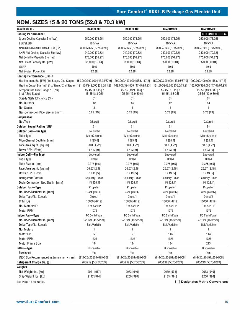
Model RKKL- B240DL30E B240DL40E B240DM30E B240DM40E
Cooling Performance1 CONTINUEDGross Cooling Capacity Btu [kW] 250,000 [73.25] 250,000 [73.25] 250,000 [73.25] 250,000 [73.25]
EER/SEER2 10.5/NA 10.5/NA 10.5/NA 10.5/NA
Nominal CFM/AHRI Rated CFM [L/s] 8000/7825 [3775/3693] 8000/7825 [3775/3693] 8000/7825 [3775/3693] 8000/7825 [3775/3693]
AHRI Net Cooling Capacity Btu [kW] 240,000 [70.32] 240,000 [70.32] 240,000 [70.32] 240,000 [70.32]
Net Sensible Capacity Btu [kW] 175,000 [51.27] 175,000 [51.27] 175,000 [51.27] 175,000 [51.27]
Net Latent Capacity Btu [kW] 65,000 [19.04] 65,000 [19.04] 65,000 [19.04] 65,000 [19.04]
IEER3 10.5 10.5 10.5 10.5
Net System Power kW 22.88 22.88 22.88 22.88
Heating Performance (Gas)4
Heating Input Btu [kW] (1st Stage / 2nd Stage) 150,000/300,000 [43.95/87.9] 200,000/400,000 [58.6/117.2] 150,000/300,000 [43.95/87.9] 200,000/400,000 [58.6/117.2]
Heating Output Btu [kW] (1st Stage / 2nd Stage) 121,500/243,000 [35.6/71.2] 162,000/324,000 [47.47/94.93] 121,500/243,000 [35.6/71.2] 162,000/324,000 [47.47/94.93]
Temperature Rise Range °F [°C](1st / 2nd Stage)
15-45 [8.3-25] /15-45 [8.3-25]
25-55 [13.9-30.6] /25-55 [13.9-30.6]
15-45 [8.3-25] /15-45 [8.3-25]
25-55 [13.9-30.6] /25-55 [13.9-30.6]
Steady State Efficiency (%) 81 81 81 81
No. Burners 12 14 12 14
No. Stages 2 2 2 2
Gas Connection Pipe Size in. [mm] 0.75 [19] 0.75 [19] 0.75 [19] 0.75 [19]
CompressorNo./Type 2/Scroll 2/Scroll 2/Scroll 2/Scroll
Outdoor Sound Rating (dB)5 91 91 91 91
Outdoor Coil—Fin Type Louvered Louvered Louvered Louvered
Tube Type MicroChannel MicroChannel MicroChannel MicroChannel
MicroChannel Depth in. [mm] 1 [25.4] 1 [25.4] 1 [25.4] 1 [25.4]
Face Area sq. ft. [sq. m] 50.8 [4.72] 50.8 [4.72] 50.8 [4.72] 50.8 [4.72]
Rows / FPI [FPcm] 1 / 23 [9] 1 / 23 [9] 1 / 23 [9] 1 / 23 [9]
Indoor Coil—Fin Type Louvered Louvered Louvered Louvered
Tube Type Rifled Rifled Rifled Rifled
Tube Size in. [mm] 0.375 [9.5] 0.375 [9.5] 0.375 [9.5] 0.375 [9.5]
Face Area sq. ft. [sq. m] 26.67 [2.48] 26.67 [2.48] 26.67 [2.48] 26.67 [2.48]
Rows / FPI [FPcm] 3 / 13 [5] 3 / 13 [5] 3 / 13 [5] 3 / 13 [5]
Refrigerant Control Capillary Tubes Capillary Tubes Capillary Tubes Capillary Tubes
Drain Connection No./Size in. [mm] 1/1 [25.4] 1/1 [25.4] 1/1 [25.4] 1/1 [25.4]
Outdoor Fan—Type Propeller Propeller Propeller Propeller
No. Used/Diameter in. [mm] 3/24 [609.6] 3/24 [609.6] 3/24 [609.6] 3/24 [609.6]
Drive Type/No. Speeds Direct/1 Direct/1 Direct/1 Direct/1
CFM [L/s] 10000 [4719] 10000 [4719] 10000 [4719] 10000 [4719]
No. Motors/HP 3 at 1/2 HP 3 at 1/2 HP 3 at 1/2 HP 3 at 1/2 HP
Motor RPM 1075 1075 1075 1075
Indoor Fan—Type FC Centrifugal FC Centrifugal FC Centrifugal FC Centrifugal
No. Used/Diameter in. [mm] 2/18x9 [457x229] 2/18x9 [457x229] 2/18x9 [457x229] 2/18x9 [457x229]
Drive Type/No. Speeds Belt/Variable Belt/Variable Belt/Variable Belt/Variable
No. Motors 1 1 1 1
Motor HP 5 5 7 1/2 7 1/2
Motor RPM 1725 1725 1725 1725
Motor Frame Size 184 184 184 213
Filter—Type Disposable Disposable Disposable Disposable
Furnished Yes Yes Yes Yes
(NO.) Size Recommended in. [mm x mm x mm] (8)2x25x20 [51x635x508] (8)2x25x20 [51x635x508] (8)2x25x20 [51x635x508] (8)2x25x20 [51x635x508]
Refrigerant Charge Oz. [g] 200/219 [5670/6209] 200/219 [5670/6209] 200/219 [5670/6209] 200/219 [5670/6209]
WeightsNet Weight lbs. [kg] 2021 [917] 2073 [940] 2059 [934] 2073 [940]
Ship Weight lbs. [kg] 2147 [974] 2200 [998] 2185 [991] 2200 [998]
NOM. SIZES 15 & 20 TONS [52.8 & 70.3 kW]
See Page 18 for Notes. [ ] Designates Metric Conversions
Sure Comfort® RKKL-B Package Gas Electric Unit
16 www.SureComfort.com
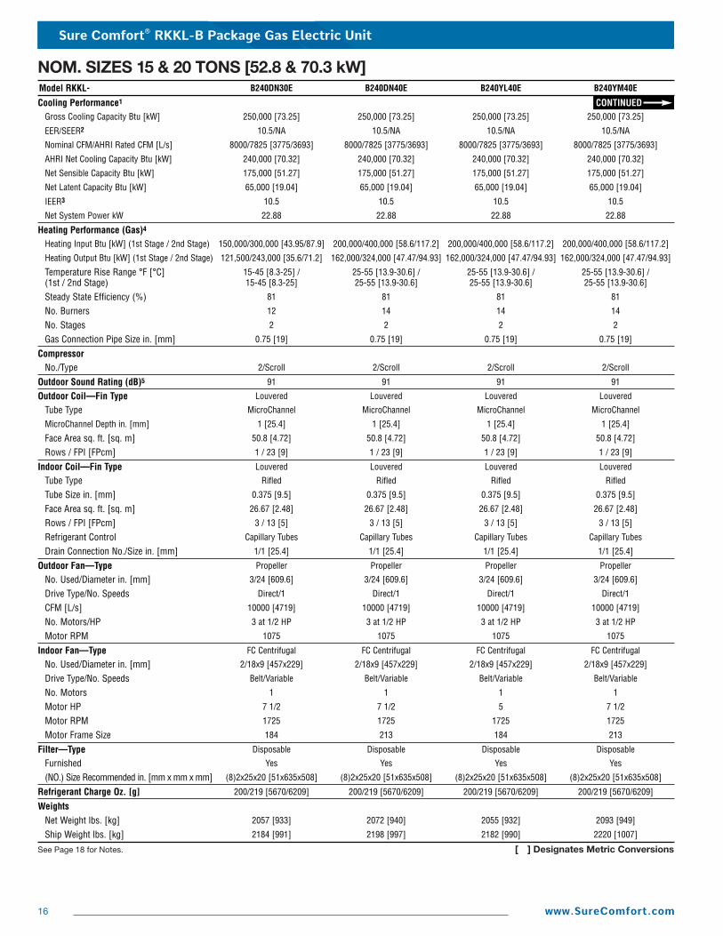
Model RKKL- B240DN30E B240DN40E B240YL40E B240YM40E
Cooling Performance1 CONTINUEDGross Cooling Capacity Btu [kW] 250,000 [73.25] 250,000 [73.25] 250,000 [73.25] 250,000 [73.25]
EER/SEER2 10.5/NA 10.5/NA 10.5/NA 10.5/NA
Nominal CFM/AHRI Rated CFM [L/s] 8000/7825 [3775/3693] 8000/7825 [3775/3693] 8000/7825 [3775/3693] 8000/7825 [3775/3693]
AHRI Net Cooling Capacity Btu [kW] 240,000 [70.32] 240,000 [70.32] 240,000 [70.32] 240,000 [70.32]
Net Sensible Capacity Btu [kW] 175,000 [51.27] 175,000 [51.27] 175,000 [51.27] 175,000 [51.27]
Net Latent Capacity Btu [kW] 65,000 [19.04] 65,000 [19.04] 65,000 [19.04] 65,000 [19.04]
IEER3 10.5 10.5 10.5 10.5
Net System Power kW 22.88 22.88 22.88 22.88
Heating Performance (Gas)4
Heating Input Btu [kW] (1st Stage / 2nd Stage) 150,000/300,000 [43.95/87.9] 200,000/400,000 [58.6/117.2] 200,000/400,000 [58.6/117.2] 200,000/400,000 [58.6/117.2]
Heating Output Btu [kW] (1st Stage / 2nd Stage) 121,500/243,000 [35.6/71.2] 162,000/324,000 [47.47/94.93] 162,000/324,000 [47.47/94.93] 162,000/324,000 [47.47/94.93]
Temperature Rise Range °F [°C](1st / 2nd Stage)
15-45 [8.3-25] /15-45 [8.3-25]
25-55 [13.9-30.6] /25-55 [13.9-30.6]
25-55 [13.9-30.6] /25-55 [13.9-30.6]
25-55 [13.9-30.6] /25-55 [13.9-30.6]
Steady State Efficiency (%) 81 81 81 81
No. Burners 12 14 14 14
No. Stages 2 2 2 2
Gas Connection Pipe Size in. [mm] 0.75 [19] 0.75 [19] 0.75 [19] 0.75 [19]
CompressorNo./Type 2/Scroll 2/Scroll 2/Scroll 2/Scroll
Outdoor Sound Rating (dB)5 91 91 91 91
Outdoor Coil—Fin Type Louvered Louvered Louvered Louvered
Tube Type MicroChannel MicroChannel MicroChannel MicroChannel
MicroChannel Depth in. [mm] 1 [25.4] 1 [25.4] 1 [25.4] 1 [25.4]
Face Area sq. ft. [sq. m] 50.8 [4.72] 50.8 [4.72] 50.8 [4.72] 50.8 [4.72]
Rows / FPI [FPcm] 1 / 23 [9] 1 / 23 [9] 1 / 23 [9] 1 / 23 [9]
Indoor Coil—Fin Type Louvered Louvered Louvered Louvered
Tube Type Rifled Rifled Rifled Rifled
Tube Size in. [mm] 0.375 [9.5] 0.375 [9.5] 0.375 [9.5] 0.375 [9.5]
Face Area sq. ft. [sq. m] 26.67 [2.48] 26.67 [2.48] 26.67 [2.48] 26.67 [2.48]
Rows / FPI [FPcm] 3 / 13 [5] 3 / 13 [5] 3 / 13 [5] 3 / 13 [5]
Refrigerant Control Capillary Tubes Capillary Tubes Capillary Tubes Capillary Tubes
Drain Connection No./Size in. [mm] 1/1 [25.4] 1/1 [25.4] 1/1 [25.4] 1/1 [25.4]
Outdoor Fan—Type Propeller Propeller Propeller Propeller
No. Used/Diameter in. [mm] 3/24 [609.6] 3/24 [609.6] 3/24 [609.6] 3/24 [609.6]
Drive Type/No. Speeds Direct/1 Direct/1 Direct/1 Direct/1
CFM [L/s] 10000 [4719] 10000 [4719] 10000 [4719] 10000 [4719]
No. Motors/HP 3 at 1/2 HP 3 at 1/2 HP 3 at 1/2 HP 3 at 1/2 HP
Motor RPM 1075 1075 1075 1075
Indoor Fan—Type FC Centrifugal FC Centrifugal FC Centrifugal FC Centrifugal
No. Used/Diameter in. [mm] 2/18x9 [457x229] 2/18x9 [457x229] 2/18x9 [457x229] 2/18x9 [457x229]
Drive Type/No. Speeds Belt/Variable Belt/Variable Belt/Variable Belt/Variable
No. Motors 1 1 1 1
Motor HP 7 1/2 7 1/2 5 7 1/2
Motor RPM 1725 1725 1725 1725
Motor Frame Size 184 213 184 213
Filter—Type Disposable Disposable Disposable Disposable
Furnished Yes Yes Yes Yes
(NO.) Size Recommended in. [mm x mm x mm] (8)2x25x20 [51x635x508] (8)2x25x20 [51x635x508] (8)2x25x20 [51x635x508] (8)2x25x20 [51x635x508]
Refrigerant Charge Oz. [g] 200/219 [5670/6209] 200/219 [5670/6209] 200/219 [5670/6209] 200/219 [5670/6209]
WeightsNet Weight lbs. [kg] 2057 [933] 2072 [940] 2055 [932] 2093 [949]
Ship Weight lbs. [kg] 2184 [991] 2198 [997] 2182 [990] 2220 [1007]
NOM. SIZES 15 & 20 TONS [52.8 & 70.3 kW]
See Page 18 for Notes. [ ] Designates Metric Conversions
Sure Comfort® RKKL-B Package Gas Electric Unit
17www.SureComfort.com
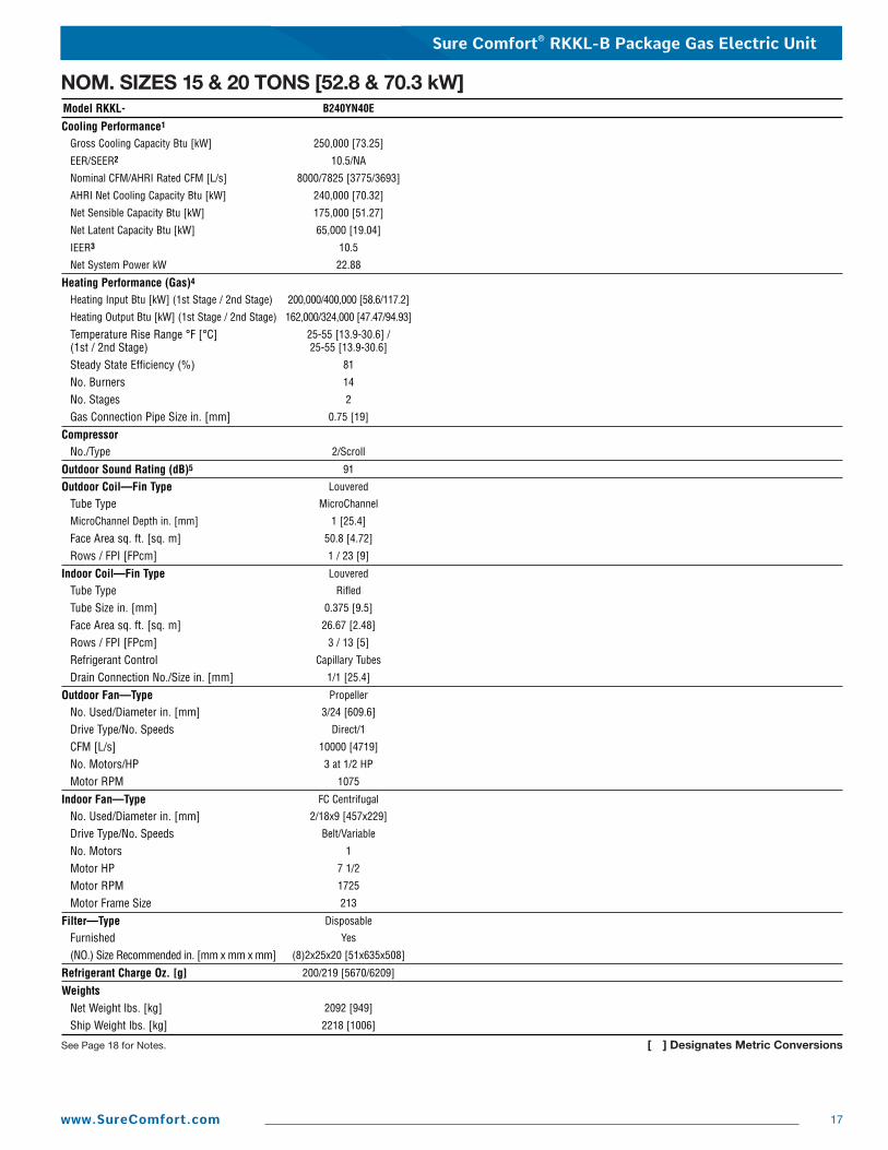
Model RKKL- B240YN40E
Cooling Performance1
Gross Cooling Capacity Btu [kW] 250,000 [73.25]
EER/SEER2 10.5/NA
Nominal CFM/AHRI Rated CFM [L/s] 8000/7825 [3775/3693]
AHRI Net Cooling Capacity Btu [kW] 240,000 [70.32]
Net Sensible Capacity Btu [kW] 175,000 [51.27]
Net Latent Capacity Btu [kW] 65,000 [19.04]
IEER3 10.5
Net System Power kW 22.88
Heating Performance (Gas)4
Heating Input Btu [kW] (1st Stage / 2nd Stage) 200,000/400,000 [58.6/117.2]
Heating Output Btu [kW] (1st Stage / 2nd Stage) 162,000/324,000 [47.47/94.93]
Temperature Rise Range °F [°C](1st / 2nd Stage)
25-55 [13.9-30.6] / 25-55 [13.9-30.6]
Steady State Efficiency (%) 81
No. Burners 14
No. Stages 2
Gas Connection Pipe Size in. [mm] 0.75 [19]
CompressorNo./Type 2/Scroll
Outdoor Sound Rating (dB)5 91
Outdoor Coil—Fin Type Louvered
Tube Type MicroChannel
MicroChannel Depth in. [mm] 1 [25.4]
Face Area sq. ft. [sq. m] 50.8 [4.72]
Rows / FPI [FPcm] 1 / 23 [9]
Indoor Coil—Fin Type Louvered
Tube Type Rifled
Tube Size in. [mm] 0.375 [9.5]
Face Area sq. ft. [sq. m] 26.67 [2.48]
Rows / FPI [FPcm] 3 / 13 [5]
Refrigerant Control Capillary Tubes
Drain Connection No./Size in. [mm] 1/1 [25.4]
Outdoor Fan—Type Propeller
No. Used/Diameter in. [mm] 3/24 [609.6]
Drive Type/No. Speeds Direct/1
CFM [L/s] 10000 [4719]
No. Motors/HP 3 at 1/2 HP
Motor RPM 1075
Indoor Fan—Type FC Centrifugal
No. Used/Diameter in. [mm] 2/18x9 [457x229]
Drive Type/No. Speeds Belt/Variable
No. Motors 1
Motor HP 7 1/2
Motor RPM 1725
Motor Frame Size 213
Filter—Type Disposable
Furnished Yes
(NO.) Size Recommended in. [mm x mm x mm] (8)2x25x20 [51x635x508]
Refrigerant Charge Oz. [g] 200/219 [5670/6209]
WeightsNet Weight lbs. [kg] 2092 [949]
Ship Weight lbs. [kg] 2218 [1006]
NOM. SIZES 15 & 20 TONS [52.8 & 70.3 kW]
See Page 18 for Notes. [ ] Designates Metric Conversions
Sure Comfort® RKKL-B Package Gas Electric Unit
18 www.SureComfort.com
NOTES:1. Cooling Performance is rated at 95° F ambient, 80° F entering dry bulb, 67° F entering wet bulb. Gross capacity does
not include the effect of fan motor heat. AHRI capacity is net and includes the effect of fan motor heat. Units aresuitable for operation to �20% of nominal cfm. Units are certified in accordance with the Unitary Air ConditionerEquipment certification program, which is based on AHRI Standard 210/240 or 340/360.
2. EER and/or SEER are rated at AHRI conditions and in accordance with DOE test procedures.
3. IEER is rated in accordance with AHRI Standard 340/360.
4. Heating Performance limit settings and rating data were established and approved under laboratory test conditionsusing American National Standard Institute standards. Ratings shown are for elevations up to 2000 feet. For elevationsabove 2000 feet, ratings should be reduced at the rate of 4% for each 1000 feet above sea level.
5. Outdoor Sound Rating shown is tested in accordance with AHRI Standard 270.
Sure Comfort® RKKL-B Package Gas Electric Unit
19www.SureComfort.com
ENTERING INDOOR AIR @ 80°F [26.7°C] dbE ➀wbE 71°F [21.7°C] 67°F [19.4°C] 63°F [17.2°C]
CFM [L/s] 7200 [3398] 5500 [2596] 4800 [2265] 7200 [3398] 5500 [2596] 4800 [2265] 7200 [3398] 5500 [2596] 4800 [2265]DR ➀ 0.04 0.1 0.13 0.04 0.1 0.13 0.04 0.1 0.13
OUTDOOR
DRY
BULB
TEMPERATURE
°F[°C]
75[23.9]
Total BTUH [kW]Sens BTUH [kW]Power
205.5 [60.2]133.5 [39.1]
12.1
194.6 [57.0]105.8 [31.0]
11.8
190.1 [55.7]95.3 [27.9]
11.7
197.3 [57.8]162.0 [47.5]
12.0
186.8 [54.7]131.1 [38.4]
11.6
182.5 [53.5]119.3 [35.0]
11.5
190.6 [55.9]184.8 [54.2]
11.8
180.5 [52.9]151.4 [44.4]
11.5
176.3 [51.7]138.5 [40.6]
11.3
80[26.7]
Total BTUH [kW]Sens BTUH [kW]Power
203.2 [59.6]134.3 [39.4]
12.7
192.4 [56.4]106.6 [31.3]
12.4
187.9 [55.1]96.0 [28.1]
12.2
194.9 [57.1]162.7 [47.7]
12.5
184.6 [54.1]131.9 [38.7]
12.2
180.3 [52.8]120.0 [35.2]
12.1
188.3 [55.2]185.6 [54.4]
12.4
178.3 [52.3]152.2 [44.6]
12.0
174.1 [51.0]139.2 [40.8]
11.9
85[29.4]
Total BTUH [kW]Sens BTUH [kW]Power
200.3 [58.7]134.3 [39.4]
13.4
189.7 [55.6]106.8 [31.3]
13.0
185.3 [54.3]96.3 [28.2]
12.9
192.1 [56.3]162.8 [47.7]
13.2
181.8 [53.3]132.0 [38.7]
12.8
177.6 [52.0]120.2 [35.2]
12.7
185.4 [54.3]185.4 [54.3]
13.0
175.5 [51.4]152.3 [44.6]
12.7
171.5 [50.3]139.5 [40.9]
12.5
90[32.2]
Total BTUH [kW]Sens BTUH [kW]Power
196.9 [57.7]133.5 [39.1]
14.0
186.4 [54.6]106.2 [31.1]
13.7
182.1 [53.4]95.8 [28.1]
13.5
188.6 [55.3]161.9 [47.5]
13.9
178.6 [52.3]131.5 [38.5]
13.5
174.5 [51.1]119.8 [35.1]
13.3
182.0 [53.3]182.0 [53.3]
13.7
172.3 [50.5]151.8 [44.5]
13.3
168.3 [49.3]139.0 [40.7]
13.2
95[35]
Total BTUH [kW]Sens BTUH [kW]Power
192.9 [56.5]131.8 [38.6]
14.8
182.6 [53.5]104.9 [30.8]
14.4
178.4 [52.3]94.7 [27.8]
14.2
184.6 [54.1]160.2 [47.0]
14.6
174.8 [51.2]130.2 [38.2]
14.2
170.8 [50.1]118.7 [34.8]
14.0
178.0 [52.2]178.0 [52.2]
14.4
168.5 [49.4]150.5 [44.1]
14.0
164.6 [48.2]137.9 [40.4]
13.9
100[37.8]
Total BTUH [kW]Sens BTUH [kW]Power
188.4 [55.2]129.3 [37.9]
15.5
178.3 [52.3]102.9 [30.2]
15.1
174.2 [51.1]92.9 [27.2]
14.9
180.1 [52.8]157.8 [46.3]
15.3
170.5 [50.0]128.3 [37.6]
14.9
166.6 [48.8]117.0 [34.3]
14.8
173.4 [50.8]173.4 [50.8]
15.2
164.2 [48.1]148.6 [43.6]
14.8
160.4 [47.0]136.2 [39.9]
14.6
105[40.6]
Total BTUH [kW]Sens BTUH [kW]Power
183.3 [53.7]126.0 [36.9]
16.3
173.5 [50.8]100.3 [29.4]
15.9
169.5 [49.7]90.6 [26.6]
15.7
175.0 [51.3]154.5 [45.3]
16.1
165.7 [48.6]125.7 [36.8]
15.7
161.9 [47.4]114.7 [33.6]
15.5
168.3 [49.3]168.3 [49.3]
16.0
159.4 [46.7]146.0 [42.8]
15.5
155.7 [45.6]133.8 [39.2]
15.4
110[43.3]
Total BTUH [kW]Sens BTUH [kW]Power
177.6 [52.0]121.9 [35.7]
17.1
168.2 [49.3]97.1 [28.5]
16.7
164.3 [48.2]87.7 [25.7]
16.5
169.4 [49.6]150.4 [44.1]
17.0
160.4 [47.0]122.4 [35.9]
16.5
156.6 [45.9]111.6 [32.7]
16.3
162.7 [47.7]162.7 [47.7]
16.8
154.0 [45.1]142.6 [41.8]
16.4
150.5 [44.1]130.8 [38.3]
16.2
115[46.1]
Total BTUH [kW]Sens BTUH [kW]Power
171.4 [50.2]116.8 [34.2]
18.0
162.3 [47.6]93.0 [27.3]
17.5
158.6 [46.5]84.0 [24.6]
17.4
163.2 [47.8]145.3 [42.6]
17.9
154.5 [45.3]118.3 [34.7]
17.4
150.9 [44.2]107.9 [31.6]
17.2
156.5 [45.9]156.5 [45.9]
17.7
148.2 [43.4]138.6 [40.6]
17.2
144.8 [42.4]127.2 [37.3]
17.0
ENTERING INDOOR AIR @ 80°F [26.7°C] dbE ➀wbE 71°F [21.7°C] 67°F [19.4°C] 63°F [17.2°C]
CFM [L/s] 9600 [4531] 7825 [3693] 6400 [3020] 9600 [4531] 7825 [3693] 6400 [3020] 9600 [4531] 7825 [3693] 6400 [3020]DR ➀ 0.06 0.11 0.15 0.06 0.11 0.15 0.06 0.11 0.15
OUTDOORDRYBULBTEMPERATURE°F
[°C]
75[23.9]
Total BTUH [kW]Sens BTUH [kW]Power
295.2 [86.5]188.5 [55.3]
17.0
283.5 [83.1]158.8 [46.5]
16.6
274.1 [80.3]136.7 [40.1]
16.4
281.3 [82.4]226.4 [66.4]
16.7
270.2 [79.2]193.6 [56.7]
16.4
261.3 [76.6]169.0 [49.5]
16.1
271.4 [79.5]261.1 [76.5]
16.4
260.6 [76.4]225.3 [66.0]
16.1
252.0 [73.9]198.3 [58.1]
15.8
80[26.7]
Total BTUH [kW]Sens BTUH [kW]Power
291.1 [85.3]186.7 [54.7]
17.8
279.6 [81.9]157.3 [46.1]
17.4
270.4 [79.2]135.5 [39.7]
17.2
277.3 [81.3]224.6 [65.8]
17.5
266.3 [78.0]192.1 [56.3]
17.2
257.5 [75.5]167.7 [49.2]
16.9
267.3 [78.3]259.2 [76.0]
17.2
256.7 [75.2]223.8 [65.6]
16.9
248.2 [72.7]197.0 [57.7]
16.6
85[29.4]
Total BTUH [kW]Sens BTUH [kW]Power
286.3 [83.9]184.3 [54.0]
18.7
275.0 [80.6]155.4 [45.6]
18.3
265.9 [77.9]133.9 [39.3]
18.0
272.5 [79.9]222.3 [65.2]
18.4
261.7 [76.7]190.2 [55.8]
18.0
253.0 [74.1]166.1 [48.7]
17.7
262.5 [76.9]256.9 [75.3]
18.1
252.1 [73.9]221.9 [65.0]
17.7
243.7 [71.4]195.4 [57.3]
17.4
90[32.2]
Total BTUH [kW]Sens BTUH [kW]Power
280.8 [82.3]181.7 [53.3]
19.6
269.6 [79.0]153.1 [44.9]
19.2
260.7 [76.4]131.9 [38.7]
18.9
266.9 [78.2]219.5 [64.3]
19.3
256.3 [75.1]187.9 [55.1]
18.9
247.8 [72.6]164.2 [48.1]
18.6
256.9 [75.3]254.1 [74.5]
19.0
246.7 [72.3]219.6 [64.4]
18.6
238.6 [69.9]193.5 [56.7]
18.3
95[35]
Total BTUH [kW]Sens BTUH [kW]Power
274.4 [80.4]178.4 [52.3]
20.6
263.6 [77.3]150.5 [44.1]
20.2
254.9 [74.7]129.7 [38.0]
19.8
260.6 [76.4]216.3 [63.4]
20.3
250.3 [73.4]185.3 [54.3]
19.9
242.0 [70.9]162.0 [47.5]
19.6
250.6 [73.4]250.6 [73.5]
20.0
240.7 [70.5]217.0 [63.6]
19.6
232.7 [68.2]191.2 [56.0]
19.3
100[37.8]
Total BTUH [kW]Sens BTUH [kW]Power
267.4 [78.4]174.7 [51.2]
21.6
256.8 [75.3]147.4 [43.2]
21.2
248.3 [72.8]127.1 [37.3]
20.8
253.5 [74.3]212.5 [62.3]
21.3
243.5 [71.4]182.2 [53.4]
20.9
235.4 [69.0]159.3 [46.7]
20.5
243.5 [71.4]243.5 [71.4]
21.0
233.9 [68.5]214.0 [62.7]
20.6
226.1 [66.3]188.7 [55.3]
20.3
105[40.6]
Total BTUH [kW]Sens BTUH [kW]Power
259.6 [76.1]170.6 [50.0]
22.7
249.3 [73.1]144.0 [42.2]
22.2
241.0 [70.6]124.2 [36.4]
21.9
245.7 [72.0]208.5 [61.1]
22.4
236.0 [69.2]178.8 [52.4]
21.9
228.2 [66.9]156.5 [45.9]
21.6
235.7 [69.1]235.7 [69.1]
22.1
226.4 [66.4]210.5 [61.7]
21.7
218.9 [64.2]185.7 [54.4]
21.3
110[43.3]
Total BTUH [kW]Sens BTUH [kW]Power
251.0 [73.6]166.1 [48.7]
23.8
241.1 [70.7]140.3 [41.1]
23.3
233.1 [68.3]121.1 [35.5]
22.9
237.1 [69.5]203.9 [59.8]
23.5
227.7 [66.7]175.0 [51.3]
23.0
220.2 [64.5]153.3 [44.9]
22.7
227.1 [66.6]227.1 [66.6]
23.2
218.1 [63.9]206.7 [60.6]
22.8
210.9 [61.8]182.5 [53.5]
22.4
115[46.1]
Total BTUH [kW]Sens BTUH [kW]Power
241.7 [70.8]161.0 [47.2]
25.0
232.1 [68.0]136.0 [39.9]
24.5
224.4 [65.8]117.4 [34.4]
24.1
227.8 [66.8]198.8 [58.3]
24.7
218.8 [64.1]170.8 [50.1]
24.2
211.5 [62.0]149.6 [43.9]
23.8
217.8 [63.8]217.8 [63.8]
24.4
209.2 [61.3]202.5 [59.4]
23.9
202.3 [59.3]179.0 [52.5]
23.5
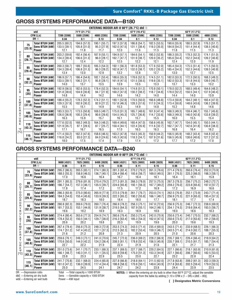
GROSS SYSTEMS PERFORMANCE DATA—B180
GROSS SYSTEMS PERFORMANCE DATA—B240
DR —Depression ratiodbE —Entering air dry bulbwbE—Entering air wet bulb
Total —Total capacity x 1000 BTUHSens —Sensible capacity x 1000 BTUHPower —KW input
NOTES: ➀ When the entering air dry bulb is other than 80°F [27°C], adjust the sensiblecapacity from the table by adding [1.10 x CFM x (1 – DR) x (dbE – 80)].
[ ] Designates Metric Conversions
Sure Comfort® RKKL-B Package Gas Electric Unit
20 www.SureComfort.com
Driv
e Pa
ckag
eL
MM
otor
H.P
. [W
]3.
0 [2
237.
1]5.
0 [3
728.
5]Bl
ower
She
ave
BK10
5HBK
105H
Mot
or S
heav
e1V
L-44
1VP-
56Tu
rns
Open
12
34
56
12
34
56
RPM
733
701
669
640
605
572
927
903
873
840
808
775
CFM
[L/s
]
4800
[226
5]
Wet
Coi
l0.
03[0
.01]
Dow
nflo
w0.
05[0
.01]
0.05
[0.0
1]
0.04
[0.0
1]
5000
[235
9]
0.05
[0.0
1]
0.05
[0.0
1]
5200
[245
4]
0.05
[0.0
1]
0.06
[0.0
1]
5400
[254
8]
0.05
[0.0
1]
0.06
[0.0
1]
5600
[264
3]
0.05
[0.0
1]
0.07
[0.0
2]
5800
[273
7]
0.05
[0.0
1]
0.08
[0.0
2]
6000
[283
1]
Dow
nflo
w E
cono
miz
er
R.A.
Dam
per O
pen
0.09
[0.0
2]
Conc
entri
c Gr
ill R
XRN-
AD80
or
RXRN
-AD8
1 &
Tra
nsiti
on R
XMC-
CJ07
0.21
[0.0
5]0.
43[0
.11]
0.13
[0.0
3]
0.25
[0.0
6]
0.10
[0.0
2]
0.28
[0.0
7]
0.10
[0.0
2]
0.32
[0.0
8]
0.11
[0.0
3]
0.35
[0.0
9]
0.12
[0.0
3]
0.39
[0.1
0]
0.13
[0.0
3]Ho
rizon
tal E
cono
miz
erR.
A. D
ampe
r Ope
n0.
00[0
.00]
0.03
[0.0
1]0.
01[0
.00]
0.01
[0.0
0]0.
02[0
.00]
0.02
[0.0
0]0.
03[0
.01]
0.46
[0.1
1]
0.04
[0.0
1]
0.14
[0.0
3]
0.06
[0.0
1]
0.09
[0.0
2]
6200
[292
6]
0.50
[0.1
2]
0.04
[0.0
1]
0.15
[0.0
4]
0.06
[0.0
1]
0.10
[0.0
2]
6400
[302
0]
0.54
[0.1
3]
0.05
[0.0
1]
0.16
[0.0
4]
0.06
[0.0
1]
0.10
[0.0
2]
6600
[311
4]
0.57
[0.1
4]
0.05
[0.0
1]
0.16
[0.0
4]
0.07
[0.0
2]
0.11
[0.0
3]
6800
[320
9]
0.61
[0.1
5]
0.06
[0.0
1]
0.17
[0.0
4]
0.08
[0.0
2]
0.12
[0.0
3]
7000
[330
3]
0.64
[0.1
6]
0.06
[0.0
1]
0.18
[0.0
4]
0.08
[0.0
2]
0.13
[0.0
3]
7200
[339
8]Re
sist
ance
— In
ches
of W
ater
[kPa
]
NOTE
: Add
com
pone
nt re
sist
ance
to d
uct r
esis
tanc
e to
det
erm
ine
tota
l ext
erna
l sta
tic p
ress
ure.
NOTE
S: 1
. Fac
tory
she
ave
setti
ngs
are
show
n in
bol
d ty
pe.
2. D
o no
t set
mot
or s
heav
e be
low
min
imum
turn
s op
en s
how
n.3.
Re-
adju
stm
ent o
f she
ave
requ
ired
to a
chie
ve ra
ted
airfl
ow a
t AHR
I min
imum
Ext
erna
l Sta
tic P
ress
ure.
4. D
rive
data
sho
wn
is fo
r hor
izon
tal a
irflo
w w
ith d
ry c
oil.
Add
com
pone
nt re
sist
ance
(bel
ow) t
o du
ct re
sist
ance
to d
eter
min
e to
tal E
xter
nal S
tatic
Pre
ssur
e.
Air
Flow
CFM
[L/s
]
Mod
el R
KKL-
B180
V
olta
ge 2
08/2
30, 4
60, 5
75 —
3 P
hase
60
HzEx
tern
al S
tatic
Pre
ssur
e—In
ches
of W
ater
[kPa
]0.
1 [.
02]
0.2
[.05
]0.
3 [.
07]
0.4
[.10
]0.
5 [.
12]
0.6
[.15
]0.
7 [.
17]
0.8
[.20
]0.
9 [.
22]
1.0
[.25
]1.
1 [.
27]
1.2
[.30
]1.
3 [.
32]
1.4
[.35
]1.
5 [.
37]
1.6
[.40
]1.
7 [.
42]
1.8
[.45
]1.
9 [.
47]
2.0
[.50
]RP
MW
RPM
WRP
MW
RPM
WRP
MW
RPM
WRP
MW
RPM
WRP
MW
RPM
WRP
MW
RPM
WRP
MW
RPM
WRP
MW
RPM
WRP
MW
RPM
WRP
MW
RPM
W48
00 [2
265]
——
——
——
——
——
589
1395
613
1488
636
1584
659
1681
681
1781
703
1883
725
1987
746
2093
766
2202
787
2313
806
2426
826
2541
845
2658
863
2778
881
2900
5000
[235
9]—
——
——
——
—57
413
7659
814
6962
115
6564
416
6366
717
6368
918
6671
019
7173
220
7875
221
8777
322
9979
324
1281
225
2883
126
4785
027
6786
828
9088
630
1452
00 [2
454]
——
——
——
——
583
1452
607
1549
630
1647
652
1748
675
1852
696
1957
718
2065
739
2175
759
2287
779
2401
799
2518
818
2637
837
2758
856
2881
874
3007
891
3134
5400
[254
8]—
——
——
——
—59
215
3461
516
3463
817
3566
118
3968
319
4570
420
5472
521
6474
622
7776
623
9278
625
0980
626
2982
527
5184
328
7586
230
0187
931
2989
732
6056
00 [2
643]
——
——
——
578
1522
601
1622
624
1724
647
1829
669
1936
691
2045
712
2156
733
2270
753
2385
773
2503
793
2623
812
2746
831
2870
849
2997
867
3126
885
3258
902
3391
5800
[273
7]—
——
——
—58
716
1261
017
1563
318
2165
519
2867
720
3869
921
5072
022
6474
123
8076
124
9978
126
2080
027
4381
928
6883
729
9685
631
2687
332
5889
133
9290
735
2860
00 [2
831]
——
——
573
1605
597
1709
620
1815
642
1923
664
2033
686
2146
707
2261
728
2378
748
2497
768
2618
788
2742
807
2868
826
2996
844
3127
862
3260
879
3394
896
3532
913
3671
6200
[292
6]—
——
—58
317
0460
618
1162
919
1965
120
3067
321
4469
522
5971
523
7773
624
9775
626
1977
627
4479
528
7081
429
9983
231
3085
132
6486
833
9988
535
3790
236
7791
838
1964
00 [3
020]
——
570
1701
593
1809
616
1918
639
2030
661
2144
682
2260
703
2378
724
2499
744
2622
764
2747
784
2874
803
3004
821
3136
839
3270
857
3406
875
3544
892
3685
908
3828
924
3973
6600
[311
4]—
—58
018
0960
319
1962
620
3164
821
4667
022
6369
123
8271
225
0373
226
2775
327
5377
228
8179
130
1181
031
4382
932
7884
634
1586
435
5488
136
9589
838
3991
439
8593
041
3368
00 [3
209]
——
591
1922
614
2035
636
2150
658
2268
679
2388
700
2510
721
2634
741
2760
761
2889
780
3020
799
3153
818
3288
836
3426
854
3566
871
3708
888
3852
904
3999
920
4147
——
7000
[330
3]57
819
2760
120
4162
421
5764
622
7566
723
9568
925
1870
926
4373
027
7075
028
9976
930
3178
831
6580
733
0182
534
3984
335
7986
137
2287
838
6789
440
1491
141
6492
643
15—
—72
00 [3
398]
589
2049
612
2165
634
2284
656
2405
677
2528
698
2654
719
2782
739
2912
759
3044
778
3178
797
3315
815
3454
833
3595
851
3739
868
3884
885
4032
901
4182
917
4335
——
——
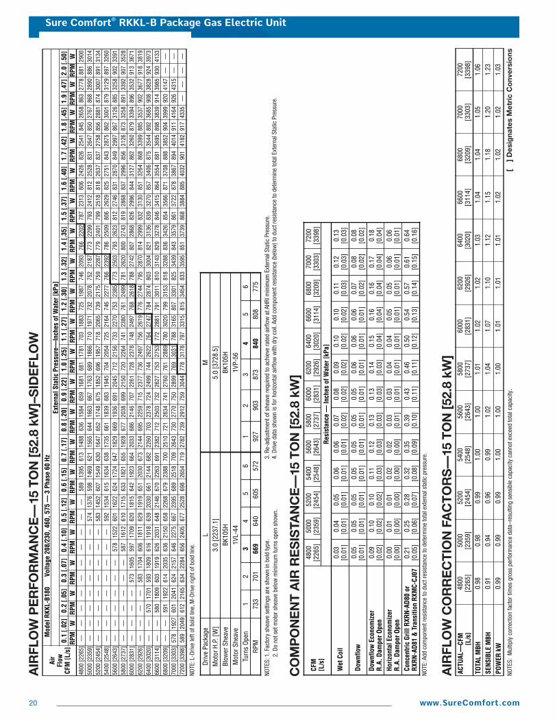
AIR
FLO
W P
ER
FOR
MA
NC
E—
15 T
ON
[52.
8 kW
]–S
IDE
FLO
W
NOTE
: L-D
rive
left
of b
old
line,
M-D
rive
right
of b
old
line.
ACTU
AL—
CFM
[L/s
]48
00[2
265]
5000
[235
9]52
00[2
454]
5400
[254
8]56
00[2
643]
5800
[273
7]60
00[2
831]
6200
[292
6]64
00[3
020]
6600
[311
4]68
00[3
209]
7000
[330
3]72
00[3
398]
TOTA
L M
BH0.
980.
980.
991.
001.
001.
011.
021.
021.
031.
041.
041.
051.
06
SENS
IBLE
MBH
0.91
0.94
0.96
0.99
1.02
1.04
1.07
1.10
1.12
1.15
1.18
1.20
1.23
POW
ER k
W0.
990.
990.
991.
001.
001.
001.
011.
011.
011.
021.
021.
021.
03
NOTE
S: M
ultip
ly c
orre
ctio
n fa
ctor
tim
es g
ross
per
form
ance
dat
a–re
sulti
ng s
ensi
ble
capa
city
can
not e
xcee
d to
tal c
apac
ity.
[
] D
esig
nate
s M
etri
c C
onv
ersi
ons
AIR
FLO
W C
OR
RE
CTI
ON
FA
CTO
RS
—15
TO
N [5
2.8
kW]
CO
MP
ON
EN
T A
IR R
ES
ISTA
NC
E—
15 T
ON
[52.
8 kW
]
Sure Comfort® RKKL-B Package Gas Electric Unit
21www.SureComfort.com
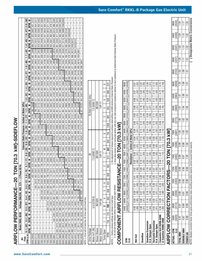
AIR
FLO
W P
ER
FOR
MA
NC
E—
20 T
ON
[70.
3 k
W]–
SID
EFL
OW
Air
Flow
CFM
[L/s
]
Mod
el R
KKL-
B240
V
olta
ge 2
08/2
30, 4
60, 5
75 —
3 P
hase
60
HzEx
tern
al S
tatic
Pre
ssur
e—In
ches
of W
ater
[kPa
]0.
1 [.
02]
0.2
[.05
]0.
3 [.
07]
0.4
[.10
]0.
5 [.
12]
0.6
[.15
]0.
7 [.
17]
0.8
[.20
]0.
9 [.
22]
1.0
[.25
]1.
1 [.
27]
1.2
[.30
]1.
3 [.
32]
1.4
[.35
]1.
5 [.
37]
1.6
[.40
]1.
7 [.
42]
1.8
[.45
]1.
9 [.
47]
2.0
[.50
]RP
MW
RPM
WRP
MW
RPM
WRP
MW
RPM
WRP
MW
RPM
WRP
MW
RPM
WRP
MW
RPM
WRP
MW
RPM
WRP
MW
RPM
WRP
MW
RPM
WRP
MW
RPM
W64
00 [3
020]
——
——
——
——
——
652
2091
676
2222
699
2354
722
2487
745
2621
766
2756
788
2893
808
3031
829
3170
848
3311
868
3453
887
3595
906
3761
923
3902
937
4121
6600
[311
4]—
——
——
——
—63
920
7466
322
0768
723
4171
024
7673
226
1375
427
5177
528
9079
630
3081
731
7283
733
1485
634
5887
536
0489
437
5091
239
1293
040
5694
442
7168
00 [3
209]
——
——
——
——
651
2194
674
2331
697
2468
720
2607
742
2747
764
2889
785
3031
805
3175
825
3321
845
3467
864
3614
883
3763
901
3913
919
4072
933
4283
950
4432
7000
[330
3]—
——
——
—63
821
8466
223
2368
524
6370
826
0473
027
4775
228
9077
330
3579
431
8281
433
2983
434
7885
336
2887
237
7989
139
3190
840
8592
642
4094
044
4895
746
0372
00 [3
398]
——
——
——
650
2318
674
2460
697
2604
719
2749
741
2895
762
3042
783
3191
804
3340
824
3492
843
3644
862
3797
880
3952
898
4108
916
4265
932
4417
947
4624
964
4784
7400
[349
2]—
——
—63
923
1566
224
6068
526
0670
827
5373
029
0275
230
5177
332
0279
333
5481
335
0883
336
6285
238
1887
139
7588
941
3490
642
9392
344
5493
846
5095
448
1097
149
7676
00 [3
586]
——
——
651
2462
674
2611
697
2760
719
2911
741
3063
762
3216
783
3371
803
3526
823
3683
842
3842
861
4001
879
4162
897
4324
914
4487
931
4651
945
4841
962
5007
978
5179
7800
[368
1]—
—64
024
6766
426
1868
727
7070
929
2373
130
7775
232
3377
333
9079
435
4881
437
0783
338
6885
240
2987
041
9288
843
5790
645
2292
346
8993
648
7895
350
4396
952
1498
653
9280
00 [3
775]
630
2475
653
2628
676
2782
699
2937
721
3094
743
3252
764
3411
784
3572
804
3733
824
3896
843
4060
861
4226
880
4392
897
4560
914
4729
931
4900
944
5084
961
5255
977
5432
993
5616
8200
[386
9]64
326
4066
627
9768
929
5471
131
1473
332
7475
434
3577
535
9879
537
6281
539
2783
440
9485
342
6287
144
3188
946
0190
647
7292
349
4593
651
3095
253
0096
954
7798
556
6010
0158
5084
00 [3
964]
657
2814
680
2974
702
3136
724
3298
745
3462
766
3627
787
3794
807
3961
826
4130
845
4300
863
4471
881
4644
899
4818
915
4993
932
5169
944
5352
961
5528
977
5710
993
5899
1008
6094
8600
[405
8]67
129
9669
331
6071
533
2573
734
9175
836
5977
838
2779
839
9781
841
6983
743
4185
645
1587
446
9089
148
6690
850
4392
552
2293
754
0895
355
8496
957
6598
559
5410
0161
48—
—88
00 [4
153]
684
3187
707
3355
728
3523
750
3693
770
3864
790
4036
810
4210
829
4385
848
4561
866
4738
884
4916
901
5096
918
5277
933
5434
946
5645
962
5826
978
6013
993
6208
1009
6408
——
9000
[424
7]69
833
8772
035
5874
237
3076
339
0378
340
7880
342
5482
244
3184
146
0985
947
8987
749
6989
551
5191
253
3592
855
1993
957
1295
558
9297
160
7998
662
7210
0264
72—
——
—92
00 [4
341]
713
3595
734
3769
755
3945
776
4122
796
4300
815
4479
834
4660
853
4842
871
5025
888
5209
905
5395
922
5582
933
5784
949
5963
964
6149
980
6342
995
6541
1010
6747
——
——
9400
[443
6]72
738
1174
839
8976
941
6878
943
4980
845
3182
847
1484
648
9886
550
8388
252
7089
954
5891
656
4793
258
3894
260
4095
862
2597
364
1898
966
1610
0468
21—
——
——
—96
00 [4
530]
741
4036
762
4218
782
4400
802
4585
821
4770
840
4956
859
5144
877
5333
894
5524
911
5715
927
5908
937
6122
952
6307
968
6498
983
6696
998
6901
——
——
——
——
Driv
e Pa
ckag
eL
MM
otor
H.P
. [W
]5.
0 [3
728.
5]7.
5 [5
592.
7]Bl
ower
She
ave
BK13
0HBK
130H
Mot
or S
heav
e1V
P-56
1VP-
71Tu
rns
Open
12
34
56
12
34
56
RPM
756
734
709
683
658
631
928
902
874
847
820
793
N (fi
eld
inst
alle
d on
ly)
7.5
[559
2.7]
BK12
0H1V
P-71
12
34
56
1009
981
955
928
899
870
NOTE
: L-D
rive
left
of b
old
line,
M-D
rive
right
of b
old
line.
CFM
[L/s
]
6400
[302
0]
Wet
Coi
l0.
00[.0
0]
Dow
nflo
w0.
06[.0
1]0.
10[.0
2]
0.02
[.00]
7600
[358
6]
0.06
[.01]
0.00
[.00]
6600
[311
4]
Dow
nflo
w E
cono
miz
er
R.A.
Dam
per O
pen
0.15
[.04]
Conc
entri
c Gr
ill R
XRN-
AD86
& T
rans
ition
RXM
C-CK
080.
26[.0
6]0.
44[.1
1]
0.20
[.05]
0.29
[.07]
0.16
[.04]
0.32
[.08]
0.16
[.04]
0.35
[.09]
0.17
[.04]
0.38
[.09]
0.18
[.04]
0.41
[.10]
0.19
[.05]
Horiz
onta
l Eco
nom
izer
R.A.
Dam
per O
pen
0.07
[.02]
0.00
[.00]
6800
[320
9]
0.04
[.01]
0.07
[.02]
0.05
[.01]
0.05
[.01]
0.06
[.01]
0.08
[.02]
0.01
[.00]
7000
[330
3]
0.06
[.01]
0.07
[.02]
Resi
stan
ce —
Inch
es o
f Wat
er [k
Pa]
0.08
[.02]
0.01
[.00]
7200
[339
8]
0.09
[.02]
0.02
[.00]
7400
[349
2]
0.47
[.12]
0.08
[.02]
0.21
[.05]
0.11
[.03]
0.03
[.01]
7800
[368
1]
0.5
[.12]
0.09
[.02]
0.22
[.05]
0.12
[.03]
0.03
[.01]
8000
[377
5]
0.53
[.13]
0.09
[.02]
0.23
[.06]
0.13
[.03]
0.04
[.01]
8200
[386
9]
0.56
[.14]
0.10
[.02]
0.24
[.06]
0.14
[.03]
0.04
[.01]
8400
[396
4]
0.59
[.15]
0.10
[.02]
0.25
[.06]
0.15
[.04]
0.05
[.01]
8600
[405
8]
0.62
[.15]
0.11
[.03]
0.26
[.06]
0.16
[.04]
0.05
[.01]
8800
[415
3]
0.65
[.16]
0.11
[.03]
0.27
[.07]
0.18
[.04]
0.06
[.01]
9000
[424
7]
0.69
[.17]
0.12
[.03]
0.28
[.07]
0.19
[.05]
0.06
[.01]
9200
[434
1]
0.72
[.18]
0.12
[.03]
0.29
[.07]
0.20
[.05]
0.07
[.02]
9400
[443
6]
0.75
[.19]
0.13
[.03]
0.30
[.07]
0.22
[.05]
0.07
[.02]
9600
[453
0]
AIR
FLO
W C
OR
RE
CTI
ON
FA
CTO
RS
—20
TO
N [7
0.3
kW]
ACTU
AL—
CFM
[L/s
]64
00[3
020]
6600
[311
4]68
00[3
209]
7000
[330
3]72
00[3
398]
7400
[349
2]76
00[3
586]
7800
[368
1]80
00[3
775]
8200
[386
9]84
00[3
964]
8600
[405
8]88
00[4
153]
9000
[424
7]92
00[4
341]
9400
[443
6]96
00[4
530]
TOTA
L M
BH0.
970.
970.
980.
980.
990.
990.
991.
001.
001.
011.
011.
021.
021.
031.
031.
041.
04
SENS
IBLE
MBH
0.87
0.89
0.91
0.93
0.95
0.97
0.98
1.00
1.02
1.04
1.06
1.08
1.09
1.11
1.13
1.15
1.17
POW
ER k
W0.
980.
990.
990.
990.
991.
001.
001.
001.
001.
001.
011.
011.
011.
011.
021.
021.
02
NOTE
S: 1
. Fac
tory
she
ave
setti
ngs
are
show
n in
bol
d ty
pe.
2. D
o no
t set
mot
or s
heav
e be
low
min
imum
turn
s op
en s
how
n.3.
Re-
adju
stm
ent o
f she
ave
requ
ired
to a
chie
ve ra
ted
airfl
ow a
t AHR
I min
imum
Ext
erna
l Sta
tic P
ress
ure.
4. D
rive
data
sho
wn
is fo
r hor
izon
tal a
irflo
w w
ith d
ry c
oil.
Add
com
pone
nt re
sist
ance
(bel
ow) t
o du
ct re
sist
ance
to d
eter
min
e to
tal E
xter
nal S
tatic
Pre
ssur
e.
CO
MP
ON
EN
T A
IRFL
OW
RE
SIS
TAN
CE
—20
TO
N [7
0.3
kW]
NOTE
S: M
ultip
ly c
orre
ctio
n fa
ctor
tim
es g
ross
per
form
ance
dat
a–re
sulti
ng s
ensi
ble
capa
city
can
not e
xcee
d to
tal c
apac
ity.
[
] D
esig
nate
s M
etri
c C
onv
ersi
ons

Sure Comfort® RKKL-B Package Gas Electric Unit
22 www.SureComfort.com
ELECTRICAL DATA – RKKL- B180CL B180CM B180DL B180DM B180YL B180YM
Unit
Info
rmat
ion
Unit Operating Voltage Range 187-253 187-253 414-506 414-506 518-633 518-633Volts 208/230 208/230 460 460 575 575
Minimum Circuit Ampacity 75/75 78/78 38 40 28 30Minimum OvercurrentProtection Device Size 90/90 90/90 45 45 30 35
Maximum OvercurrentProtection Device Size 90/90 100/100 50 50 35 35
Com
pres
sor M
otor
No. 2 2 2 2 2 2Volts 200/230 200/230 460 460 575 575Phase 3 3 3 3 3 3RPM 3450 3450 3450 3450 3450 3450
HP, Compressor 1 7 7 7 7 7 7Amps (RLA), Comp. 1 25/25 25/25 12.2 12.2 9 9Amps (LRA), Comp. 1 164/164 164/164 100 100 78 78
HP, Compressor 2 6 6 6 6 6 6Amps (RLA), Comp. 2 25/25 25/25 12.8 12.8 9.6 9.6Amps (LRA), Comp. 2 164/164 164/164 100 100 78 78
Com
pres
sor M
otor No. 3 3 3 3 3 3
Volts 208/230 208/230 460 460 575 575Phase 1 1 1 1 1 1
HP 1/2 1/2 1/2 1/2 1/2 1/2Amps (FLA, each) 2.3/2.3 2.3/2.3 1.5 1.5 1 1Amps (LRA, each) 5.6/5.6 5.6/5.6 3.1 3.1 2.2 2.2
Evap
orat
or F
an
No. 1 1 1 1 1 1Volts 208/230 208/230 460 460 575 575Phase 3 3 3 3 3 3
HP 3 5 3 5 3 5Amps (FLA, each) 11.5/11.5 14.9/14.9 4.6 6.6 3.5 5.3Amps (LRA, each) 74.5/74.5 82.6/82.6 38.1 46.3 20 39.4
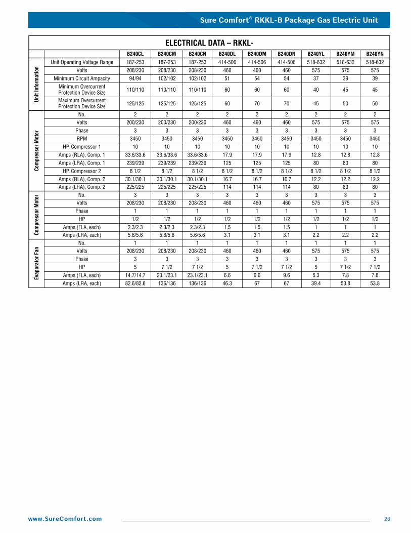
Sure Comfort® RKKL-B Package Gas Electric Unit
23www.SureComfort.com
ELECTRICAL DATA – RKKL- B240CL B240CM B240CN B240DL B240DM B240DN B240YL B240YM B240YN
Unit
Info
rmat
ion
Unit Operating Voltage Range 187-253 187-253 187-253 414-506 414-506 414-506 518-632 518-632 518-632Volts 208/230 208/230 208/230 460 460 460 575 575 575
Minimum Circuit Ampacity 94/94 102/102 102/102 51 54 54 37 39 39Minimum OvercurrentProtection Device Size 110/110 110/110 110/110 60 60 60 40 45 45
Maximum OvercurrentProtection Device Size 125/125 125/125 125/125 60 70 70 45 50 50
Com
pres
sor M
otor
No. 2 2 2 2 2 2 2 2 2Volts 200/230 200/230 200/230 460 460 460 575 575 575Phase 3 3 3 3 3 3 3 3 3RPM 3450 3450 3450 3450 3450 3450 3450 3450 3450
HP, Compressor 1 10 10 10 10 10 10 10 10 10Amps (RLA), Comp. 1 33.6/33.6 33.6/33.6 33.6/33.6 17.9 17.9 17.9 12.8 12.8 12.8Amps (LRA), Comp. 1 239/239 239/239 239/239 125 125 125 80 80 80
HP, Compressor 2 8 1/2 8 1/2 8 1/2 8 1/2 8 1/2 8 1/2 8 1/2 8 1/2 8 1/2Amps (RLA), Comp. 2 30.1/30.1 30.1/30.1 30.1/30.1 16.7 16.7 16.7 12.2 12.2 12.2Amps (LRA), Comp. 2 225/225 225/225 225/225 114 114 114 80 80 80
Com
pres
sor M
otor No. 3 3 3 3 3 3 3 3 3
Volts 208/230 208/230 208/230 460 460 460 575 575 575Phase 1 1 1 1 1 1 1 1 1
HP 1/2 1/2 1/2 1/2 1/2 1/2 1/2 1/2 1/2Amps (FLA, each) 2.3/2.3 2.3/2.3 2.3/2.3 1.5 1.5 1.5 1 1 1Amps (LRA, each) 5.6/5.6 5.6/5.6 5.6/5.6 3.1 3.1 3.1 2.2 2.2 2.2
Evap
orat
or F
an
No. 1 1 1 1 1 1 1 1 1Volts 208/230 208/230 208/230 460 460 460 575 575 575Phase 3 3 3 3 3 3 3 3 3
HP 5 7 1/2 7 1/2 5 7 1/2 7 1/2 5 7 1/2 7 1/2Amps (FLA, each) 14.7/14.7 23.1/23.1 23.1/23.1 6.6 9.6 9.6 5.3 7.8 7.8Amps (LRA, each) 82.6/82.6 136/136 136/136 46.3 67 67 39.4 53.8 53.8

Sure Comfort® RKKL-B Package Gas Electric Unit
24 www.SureComfort.com
BOTTOM VIEW
[ ] Designates Metric Conversions
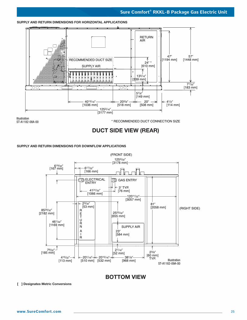
Sure Comfort® RKKL-B Package Gas Electric Unit
25www.SureComfort.com
SUPPLY AND RETURN DIMENSIONS FOR DOWNFLOW APPLICATIONS
SUPPLY AND RETURN DIMENSIONS FOR HORIZONTAL APPLICATIONS
[ ] Designates Metric Conversions
DUCT SIDE VIEW (REAR)
BOTTOM VIEW
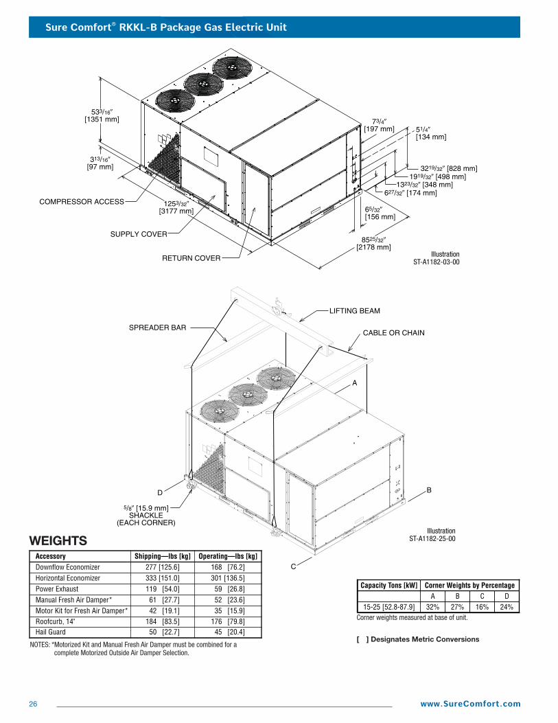
Sure Comfort® RKKL-B Package Gas Electric Unit
26 www.SureComfort.com
A B C D32% 27% 16% 24%
Capacity Tons [kW]
15-25 [52.8-87.9]
Corner Weights by Percentage
WEIGHTSAccessory Shipping—lbs [kg] Operating—lbs [kg]Downflow Economizer 277 [125.6] 168 [76.2]Horizontal Economizer 333 [151.0] 301 [136.5]Power Exhaust 119 [54.0] 59 [26.8]Manual Fresh Air Damper* 61 [27.7] 52 [23.6]Motor Kit for Fresh Air Damper* 42 [19.1] 35 [15.9]Roofcurb, 14" 184 [83.5] 176 [79.8]Hail Guard 50 [22.7] 45 [20.4]
Corner weights measured at base of unit.
[ ] Designates Metric ConversionsNOTES: *Motorized Kit and Manual Fresh Air Damper must be combined for a
complete Motorized Outside Air Damper Selection.
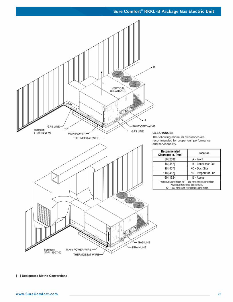
Sure Comfort® RKKL-B Package Gas Electric Unit
27www.SureComfort.com
[ ] Designates Metric Conversions
CLEARANCESThe following minimum clearances are recommended for proper unit performanceand serviceability.
RecommendedClearance In. [mm] Location
80 [2032] A - Front18 [457] B - Condenser Coil
+18 [457] +C - Duct Side*18 [457] *D - Evaporator End60 [1524] E - Above
*Without Economizer. 48" [1219 mm] With Economizer+Without Horizontal Economizer,
42" [1067 mm] with Horizontal Economizer
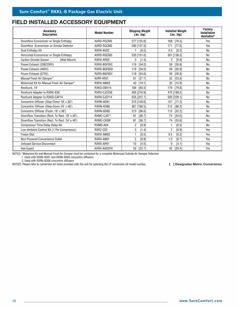
Sure Comfort® RKKL-B Package Gas Electric Unit
28 www.SureComfort.com
FIELD INSTALLED ACCESSORY EQUIPMENTAccessory
Description Model Number Shipping WeightLbs. [kg]
Installed WeightLbs. [kg]
FactoryInstallationAvailable?
Downflow Economizer w/ Single Enthalpy AXRD-PGCM3 277 [125.6] 168 [76.2] YesDownflow Economizer w/ Smoke Detector AXRD-SGCM3 280 [127.0] 171 [77.6] YesDual Enthalpy Kit RXRX-AV02 1 [0.5] 0.5 [0.2] NoHorizontal Economizer w/ Single Enthalpy AXRD-RGCM3 333 [151.0] 301 [136.5] NoCarbon Dioxide Sensor (Wall Mount) RXRX-AR02 3 [1.4] 2 [0.9] NoPower Exhaust (208/230V) RXRX-BGF05C 119 [54.0] 59 [26.8] NoPower Exhaust (460V) RXRX-BGF05D 119 [54.0] 59 [26.8] NoPower Exhaust (575V) RXRX-BGF05Y 119 [54.0] 59 [26.8] NoManual Fresh Air Damper* AXRF-KFA1 61 [27.7] 52 [23.6] NoMotorized Kit for Manual Fresh Air Damper* RXRX-AW03 42 [19.1] 35 [15.9] NoRoofcurb, 14" RXKG-CBH14 184 [83.5] 176 [79.8] NoRoofcurb Adapter to RXRK-E56 RXRX-CJCE56 465 [210.9] 415 [188.2] NoRoofcurb Adapter to RXKG-CAF14 RXRX-CJCF14 555 [251.7] 505 [229.1] NoConcentric Diffuser (Step-Down 18" x 36") RXRN-AD81 310 [140.6] 157 [71.2] NoConcentric Diffuser (Step-Down 24" x 48") RXRN-AD86 367 [166.5] 212 [96.2] NoConcentric Diffuser (Flush, 18" x 36") RXRN-AD80 213 [96.6] 115 [52.2] NoDownflow Transition (Rect. To Rect. 18" x 36") RXMC-CJ07¹ 81 [36.7] 74 [33.6] NoDownflow Transition (Rect. To Rect. 24" x 48") RXMC-CK08² 81 [36.7] 74 [33.6] NoCompressor Time-Delay Relay Kit RXMD-A04 2 [0.9] 1 [0.5] NoLow-Ambient Control Kit (1 Per Compressor) RXRZ-C02 3 [1.4] 2 [0.9] YesFreeze Stat RXRX-AM03 1 [0.5] 0.5 [0.2] YesNon-Powered Convenience Outlet RXRX-AN01 2 [0.9] 1.5 [0.7] YesUnfused Service Disconnect RXRX-AP01 10 [4.5] 9 [4.1] YesHail Guard AXRX-AAD01K 50 [22.7] 45 [20.4] Yes
NOTES: *Motorized Kit and Manual Fresh Air Damper must be combined for a complete Motorized Outside Air Damper Selection1. Used with RXRN-AD81 and RXRN-AD80 concentric diffusers2. Used with RXRN-AD86 concentric diffusers
NOTICE: Please refer to conversion kit index provided with the unit for selecting the LP conversion kit model number. [ ] Designates Metric Conversions
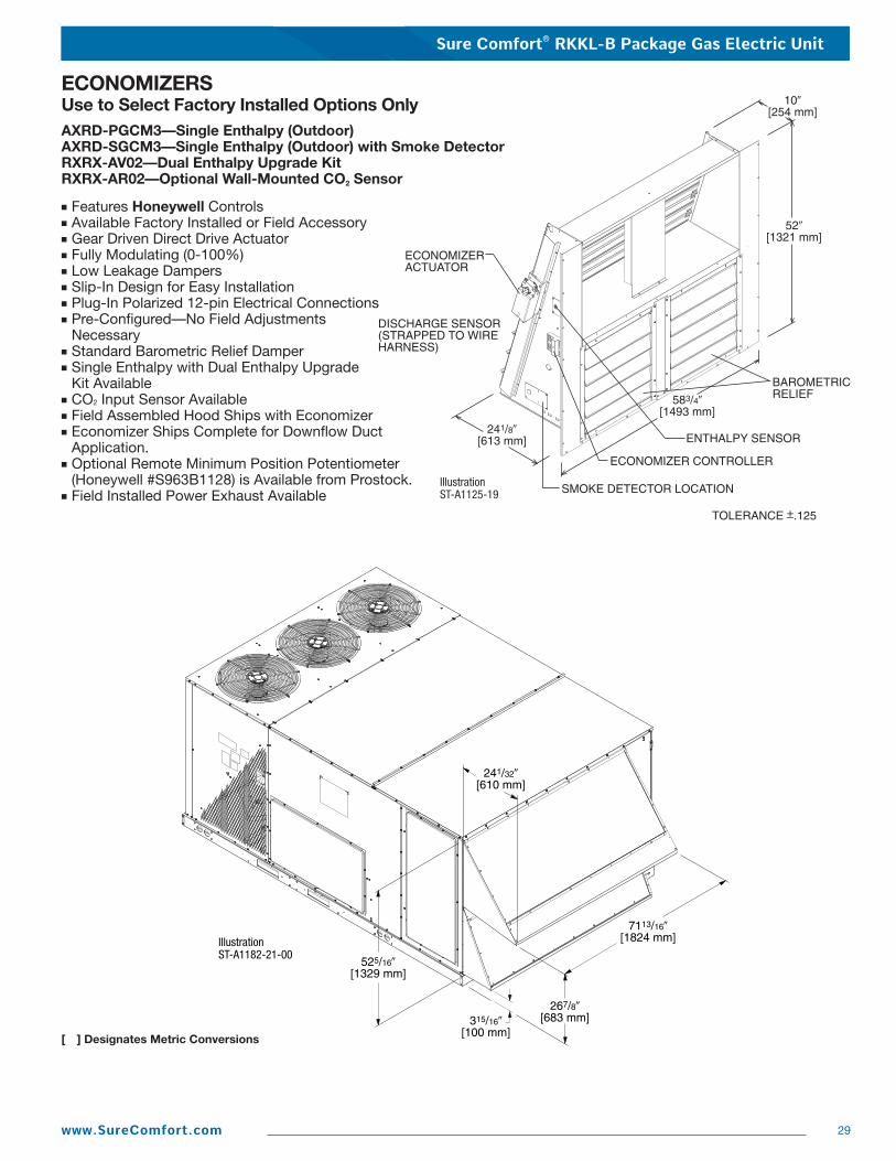
Sure Comfort® RKKL-B Package Gas Electric Unit
29www.SureComfort.com
ECONOMIZERSUse to Select Factory Installed Options OnlyAXRD-PGCM3—Single Enthalpy (Outdoor)AXRD-SGCM3—Single Enthalpy (Outdoor) with Smoke DetectorRXRX-AV02—Dual Enthalpy Upgrade KitRXRX-AR02—Optional Wall-Mounted CO2 Sensor
■ Features Honeywell Controls■ Available Factory Installed or Field Accessory■ Gear Driven Direct Drive Actuator■ Fully Modulating (0-100%)■ Low Leakage Dampers■ Slip-In Design for Easy Installation■ Plug-In Polarized 12-pin Electrical Connections■ Pre-Configured—No Field Adjustments
Necessary■ Standard Barometric Relief Damper■ Single Enthalpy with Dual Enthalpy Upgrade
Kit Available■ CO2 Input Sensor Available■ Field Assembled Hood Ships with Economizer■ Economizer Ships Complete for Downflow Duct
Application.■ Optional Remote Minimum Position Potentiometer
(Honeywell #S963B1128) is Available from Prostock.■ Field Installed Power Exhaust Available
[ ] Designates Metric Conversions
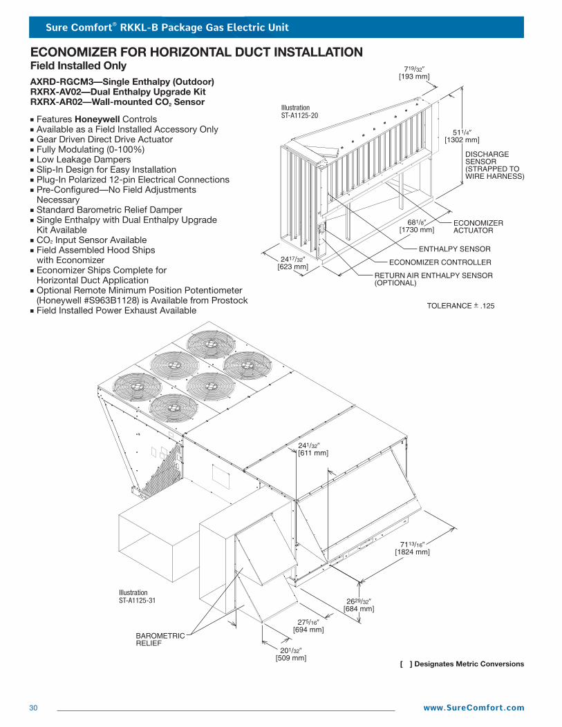
Sure Comfort® RKKL-B Package Gas Electric Unit
30 www.SureComfort.com
ECONOMIZER FOR HORIZONTAL DUCT INSTALLATIONField Installed OnlyAXRD-RGCM3—Single Enthalpy (Outdoor)RXRX-AV02—Dual Enthalpy Upgrade KitRXRX-AR02—Wall-mounted CO2 Sensor
■ Features Honeywell Controls■ Available as a Field Installed Accessory Only■ Gear Driven Direct Drive Actuator■ Fully Modulating (0-100%)■ Low Leakage Dampers■ Slip-In Design for Easy Installation■ Plug-In Polarized 12-pin Electrical Connections■ Pre-Configured—No Field Adjustments
Necessary■ Standard Barometric Relief Damper■ Single Enthalpy with Dual Enthalpy Upgrade
Kit Available■ CO2 Input Sensor Available■ Field Assembled Hood Ships
with Economizer■ Economizer Ships Complete for
Horizontal Duct Application■ Optional Remote Minimum Position Potentiometer
(Honeywell #S963B1128) is Available from Prostock■ Field Installed Power Exhaust Available
[ ] Designates Metric Conversions

Sure Comfort® RKKL-B Package Gas Electric Unit
31www.SureComfort.com
POWER EXHAUST KIT FOR AXRD-PGCM3 & SGCM3 ECONOMIZERSRXRX-BGF05 (C, D, or Y*)
*Voltage Code
VERTICAL AIRFLOW
Model No. No.of Fans Volts Phase HP
(ea.)Low Speed
RXRX-BGF05C 2 208-230 1 0.75 4100 [1935] 850 5200 [2454]
High Speed ➀
1050 5
FLA(ea.)
4.97
LRA(ea.)
RXRX-BGF05D 2 460 1 0.75 4100 [1935] 850 5200 [2454] 1050 2.2 3.4RXRX-BGF05Y 2 575 1 0.75 4100 [1935] 850 5200 [2454] 1050 1.5 2.84
CFM [L/s] ➁ RPM CFM [L/s] ➁ RPM
NOTES: ➀ Power exhaust is factory set on high speed motor tap. [ ] Designates Metric Conversions ➁ CFM is per fan at 0" w.c. external static pressure.
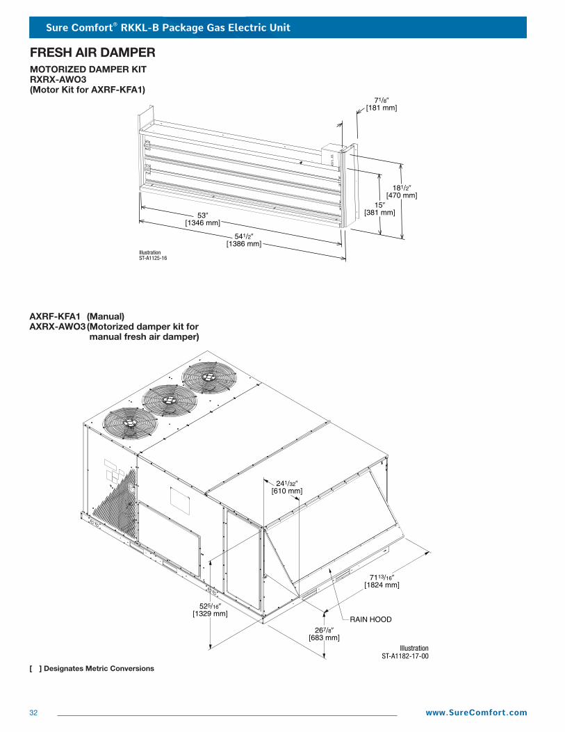
Sure Comfort® RKKL-B Package Gas Electric Unit
32 www.SureComfort.com
[ ] Designates Metric Conversions
AXRF-KFA1 (Manual)AXRX-AWO3(Motorized damper kit for
manual fresh air damper)
FRESH AIR DAMPERMOTORIZED DAMPER KITRXRX-AWO3(Motor Kit for AXRF-KFA1)

Sure Comfort® RKKL-B Package Gas Electric Unit
33www.SureComfort.com
ROOFCURBS (Full Perimeter)■ Sure Comfort’s new roofcurb designs can be utilized
on 15 & 20 ton [52.8 & 70.3 kW] models.
■ One available height (14" [356 mm]).
■ Quick assembly corners for simple and fast assembly.
■ 1" [25.4 mm] x 4" [102 mm] Nailer provided.
■ Insulating panels not required because of insulated outdoor base pan.
■ Sealing gasket (28" [711 mm]) providedwith Roofcurb.
■ Packaged for easy field assembly.
TYPICAL INSTALLATION
ROOFCURB ASSEMBLY
[ ] Designates Metric Conversions
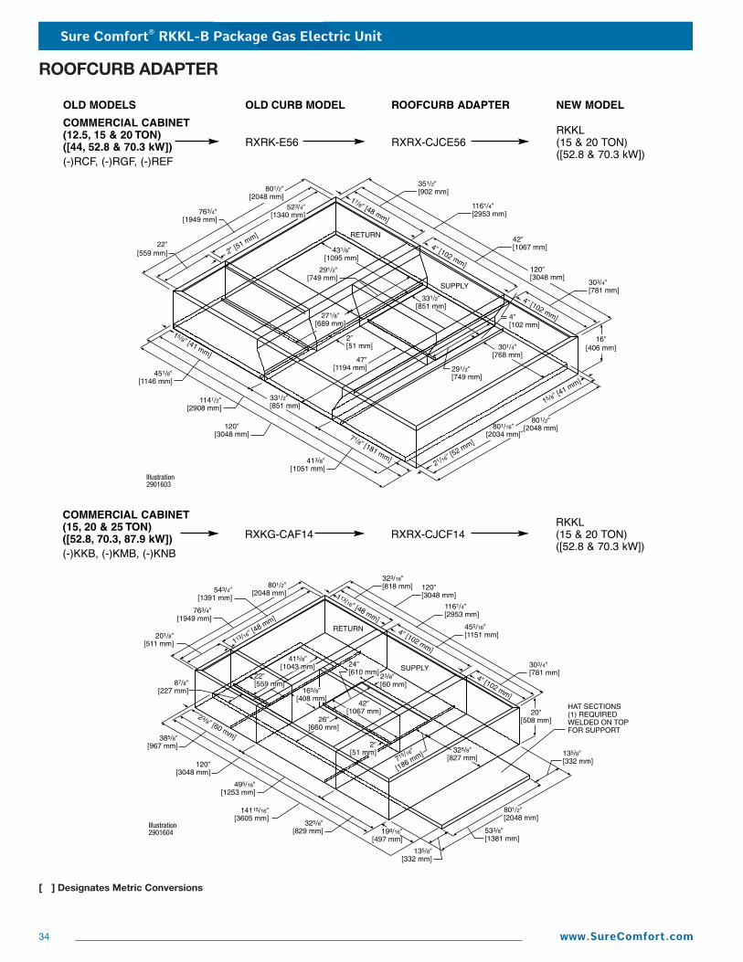
Sure Comfort® RKKL-B Package Gas Electric Unit
34 www.SureComfort.com
ROOFCURB ADAPTER
RKKL(15 & 20 TON)([52.8 & 70.3 kW])
COMMERCIAL CABINET (15, 20 & 25 TON)([52.8, 70.3, 87.9 kW])(-)KKB, (-)KMB, (-)KNB
RXKG-CAF14 RXRX-CJCF14
[ ] Designates Metric Conversions
NEW MODEL
RKKL(15 & 20 TON)([52.8 & 70.3 kW])
OLD MODELS OLD CURB MODEL ROOFCURB ADAPTER
COMMERCIAL CABINET (12.5, 15 & 20 TON)([44, 52.8 & 70.3 kW])(-)RCF, (-)RGF, (-)REF
RXRK-E56 RXRX-CJCE56
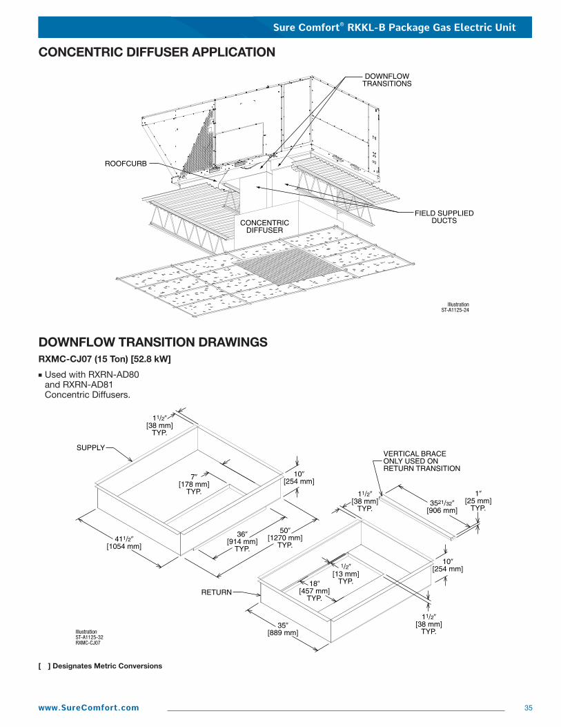
Sure Comfort® RKKL-B Package Gas Electric Unit
35www.SureComfort.com
CONCENTRIC DIFFUSER APPLICATION
DOWNFLOW TRANSITION DRAWINGSRXMC-CJ07 (15 Ton) [52.8 kW]
■ Used with RXRN-AD80and RXRN-AD81Concentric Diffusers.
[ ] Designates Metric Conversions
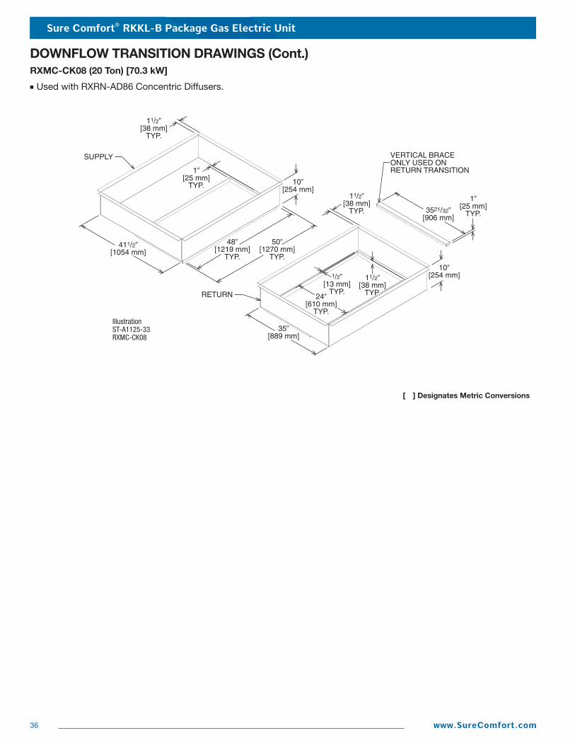
Sure Comfort® RKKL-B Package Gas Electric Unit
36 www.SureComfort.com
DOWNFLOW TRANSITION DRAWINGS (Cont.)RXMC-CK08 (20 Ton) [70.3 kW]
■ Used with RXRN-AD86 Concentric Diffusers.
[ ] Designates Metric Conversions
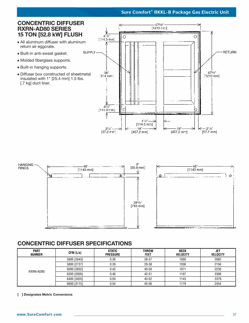
Sure Comfort® RKKL-B Package Gas Electric Unit
37www.SureComfort.com
CONCENTRIC DIFFUSER SPECIFICATIONS
CONCENTRIC DIFFUSER RXRN-AD80 SERIES15 TON [52.8 kW] FLUSH■ All aluminum diffuser with aluminum
return air eggcrate.
■ Built-in anti-sweat gasket.
■ Molded fiberglass supports.
■ Built-in hanging supports.
■ Diffuser box constructed of sheetmetal insulated with 1" [25.4 mm] 1.5 lbs. [.7 kg] duct liner.
PARTNUMBER CFM [L/s] STATIC
PRESSURETHROW
FEET
5800 [2737] 0.39 29-386000 [2832] 0.42 40-50
RXRN-AD80
5600 [2643] 0.36 28-37
107110361000
NECKVELOCITY
223021562082
JETVELOCITY
6200 [2926] 0.46 42-51 1107 23086400 [3020] 0.50 43-52 1143 23796600 [3115] 0.54 45-56 1179 2454
[ ] Designates Metric Conversions
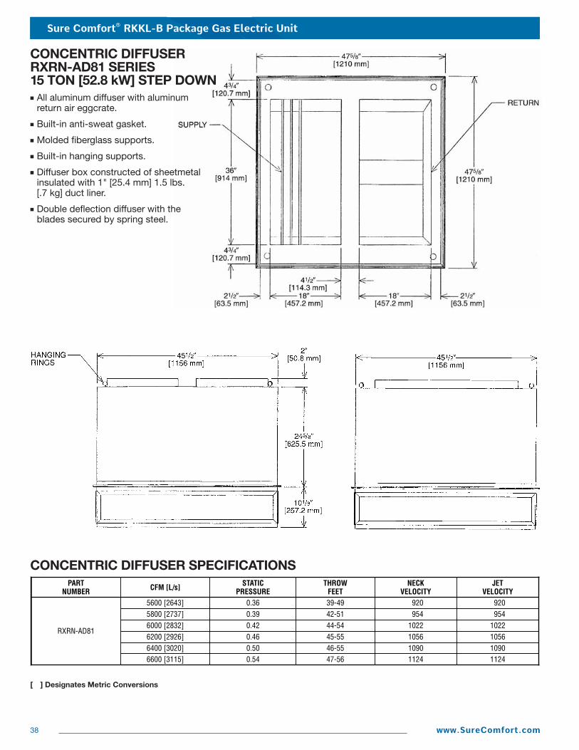
Sure Comfort® RKKL-B Package Gas Electric Unit
38 www.SureComfort.com
CONCENTRIC DIFFUSER SPECIFICATIONS
CONCENTRIC DIFFUSERRXRN-AD81 SERIES15 TON [52.8 kW] STEP DOWN■ All aluminum diffuser with aluminum
return air eggcrate.
■ Built-in anti-sweat gasket.
■ Molded fiberglass supports.
■ Built-in hanging supports.
■ Diffuser box constructed of sheetmetal insulated with 1" [25.4 mm] 1.5 lbs.[.7 kg] duct liner.
■ Double deflection diffuser with theblades secured by spring steel.
PARTNUMBER CFM [L/s] STATIC
PRESSURETHROW
FEET
1022954920
NECKVELOCITY
1022954920
JETVELOCITY
6200 [2926] 0.46 45-55 1056 10566400 [3020] 0.50 46-55 1090 10906600 [3115]
5800 [2737] 0.39 42-51
0.54 47-56 1124 1124
6000 [2832] 0.42 44-54RXRN-AD81
5600 [2643] 0.36 39-49
[ ] Designates Metric Conversions
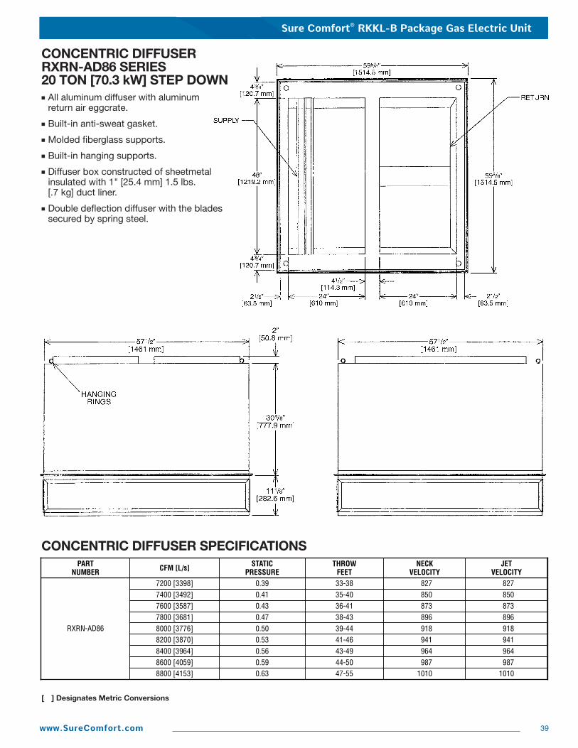
Sure Comfort® RKKL-B Package Gas Electric Unit
39www.SureComfort.com
CONCENTRIC DIFFUSER SPECIFICATIONS
CONCENTRIC DIFFUSERRXRN-AD86 SERIES20 TON [70.3 kW] STEP DOWN■ All aluminum diffuser with aluminum
return air eggcrate.
■ Built-in anti-sweat gasket.
■ Molded fiberglass supports.
■ Built-in hanging supports.
■ Diffuser box constructed of sheetmetal insulated with 1" [25.4 mm] 1.5 lbs. [.7 kg] duct liner.
■ Double deflection diffuser with the bladessecured by spring steel.
PARTNUMBER CFM [L/s] STATIC
PRESSURETHROW
FEET
873850827
NECKVELOCITY
873850827
JETVELOCITY
7800 [3681] 0.47 38-43 896 8968000 [3776] 0.50 39-44 918 9188200 [3870]
7400 [3492] 0.41 35-40
0.53 41-46 941 941
7600 [3587] 0.43 36-41
RXRN-AD86
7200 [3398] 0.39 33-38
8400 [3964] 0.56 43-49 964 9648600 [4059] 0.59 44-50 987 9878800 [4153] 0.63 47-55 1010 1010
[ ] Designates Metric Conversions
Sure Comfort® RKKL-B Package Gas Electric Unit
40 www.SureComfort.com
Guide Specifications RKKL-B180 thru B240Note about this specification: Please feel free to copy this specification directly into your building spec. This specification is written tocomply with the 2004 version of the “mask-format” as published by the Construction Specification Institute. www.csinet.org.
GAS HEAT PACKAGED ROOFTOPHVAC Guide SpecificationsSize Range: 15 to 20 Nominal TonsSection Description23 06 80 Schedules for Decentralized HVAC Equipment
23 06 80.13 Decentralized Unitary HVAC Equipment Schedule23 06 80.13.A. Rooftop unit schedule 1. Schedule is per the project specification requirements.
23 07 16 HVAC Equipment Insulation23 07 16.13 Decentralized, Rooftop Units: 1. Interior cabinet surfaces shall be insulated with a minimum 3/4-in. thick, minimum 1-1/2 lb density, flexible fiberglass insulation
bonded with a phenolic binder, with aluminum foil facing on the air side. 2. Insulation and adhesive shall meet NFPA 90A requirements for flame spread and smoke generation.
23 09 13 Instrumentation and Control Devices for HVAC23 09 13.23 Sensors and Transmitters:
23 09 33 Electric and Electronic Control System for HVAC23 09 33.13 Decentralized, Rooftop Units:23 09 93.13.A. General: 1. Shall be complete with self-contained low-voltage control circuit protected by a resettable circuit breaker on the 24-v
transformer side. 2. Shall utilize color-coded wiring. 3. The heat exchanger shall be controlled by an integrated furnace controller (IFC) microprocessor. See heat exchanger section
of this specification. 4. Unit shall include a minimum of one 9-pin screw terminal connection board for connection of control wiring.23 09 33.23.B. Safeties: 1. Compressor over-temperature, over current. 2. Low-pressure switch. 3. High-pressure switch. 4. Automatic reset, motor thermal overload protector. 5. Heating section shall be provided with the following minimum protections. a. High-temperature limit switches. b. Induced draft motor pressure switch. c. Flame rollout switch. d. Flame proving controls.23 09 93 Sequence of Operations for HVAC Controls23 09 93.13 Decentralized, Rooftop Units:23 09 93.13 INSERT SEQUENCE OF OPERATION23 40 13 Panel Air Filters23 40 13.13 Decentralized, Rooftop Units:23 40 13.13.A. Standard filter section shall 1. Shall consist of factory-installed, low velocity, throwaway 2-in. thick fiberglass filters of commercially available sizes. 2. Unit shall use only one filter size. Multiple sizes are not acceptable. 3. Filter face velocity shall not exceed 365 fpm at nominal airflows. 4. Filters shall be accessible through an access panel as described in the unit cabinet section of the specification
(23 81 19.13.H).
Sure Comfort® RKKL-B Package Gas Electric Unit
41www.SureComfort.com
23 81 19 Self-Contained Air Conditioners23 81 19.13 Small-Capacity Self-Contained Air Conditioners23 81 19.13.A. General 1. Outdoor, rooftop mounted, electrically controlled, heating and cooling unit utilizing a(n) hermetic scroll compressor(s) for
cooling duty and gas combustion for heating duty. 2. Factory assembled, single-piece heating and cooling rooftop unit. Contained within the unit enclosure shall be all factory
wiring, piping, controls, and special features required prior to field start-up. 3. Unit shall use environmentally safe, R-410A refrigerant. 4. Unit shall be installed in accordance with the manufacturer’s instructions. 5. Unit must be selected and installed in compliance with local, state, and federal codes.23 81 19.13.B. Quality Assurance 1. Unit meets ASHRAE 90.1-2004 minimum efficiency requirements. 2. 3 phase units are Energy Star qualified. 3. Unit shall be rated in accordance with AHRI Standards 210 and 360. 4. Unit shall be designed to conform to ASHRAE 15, 2001. 5. Unit shall be UL-tested and certified in accordance with ANSI Z21.47 Standards and UL-listed and certified under Canadian
standards as a total package for safety requirements. 6. Insulation and adhesive shall meet NFPA 90A requirements for flame spread and smoke generation. 7. Unit casing shall be capable of withstanding 500-hour salt spray exposure per ASTM B117 (scribed specimen). 8. Unit casing shall be capable of withstanding Federal Test Method Standard No. 141 (Method 6061) 5000-hour salt spray. 9. Unit shall be designed in accordance with ISO 9001:2000, and shall be manufactured in a facility registered by ISO
9001:2000. 10. Roof curb shall be designed to conform to NRCA Standards. 11. Unit shall be subjected to a completely automated run test on the assembly line. The data for each unit will be stored at the
factory, and must be available upon request. 12. Unit shall be designed in accordance with UL Standard 1995, including tested to withstand rain. 13. Unit shall be constructed to prevent intrusion of snow and tested to prevent snow intrusion into the control box up to 40 mph.23 81 19.13.C. Delivery, Storage, and Handling 1. Unit shall be stored and handled per manufacturer’s recommendations. 2. Lifted by crane requires either shipping top panel or spreader bars. 3. Unit shall only be stored or positioned in the upright position.23 81 19.13.E. Project Conditions 1. As specified in the contract.23 81 19.13.F. Operating Characteristics 1. Unit shall be capable of starting and running at 115°F (46°C) ambient outdoor temperature, meeting maximum load criteria of
AHRI Standard 210/240 or 360 at ± 10% voltage. 2. Compressor with standard controls shall be capable of operation down to 40°F (4°C), ambient outdoor temperatures. Acces-
sory low ambient kit is necessary if mechanically cooling at ambient temperatures below 40°F (4°C). 3. Unit shall discharge supply air vertically or horizontally as shown on contract drawings. 4. Unit shall be factory configured for vertical supply & return configurations. 5. Unit shall be field convertible from vertical to horizontal configuration.23 81 19.13.G. Electrical Requirements 1. Main power supply voltage, phase, and frequency must match those required by the manufacturer.23 81 19.13.H. Unit Cabinet 1. Unit cabinet shall be constructed of galvanized steel, and shall be bonderized and coated with a baked enamel finish on all
externally exposed surfaces. 2. Unit cabinet exterior paint shall be: film thickness, (dry) 0.003 inches minimum, gloss (per ASTM D523, 60°F / 16°C): 60,
Hardness: H-2H Pencil hardness. 3. Evaporator fan compartment interior cabinet insulation shall conform to AHRI Standards 210 or 360 minimum exterior sweat
criteria. Interior surfaces shall be insulated with a minimum 3/4-in. thick, 1 lb. density, flexible fiberglass insulation, aluminumfoil-face coated on the air side.
4. Base of unit shall have locations for thru-the-base gas and electrical connections (factory installed or field installed), standard.
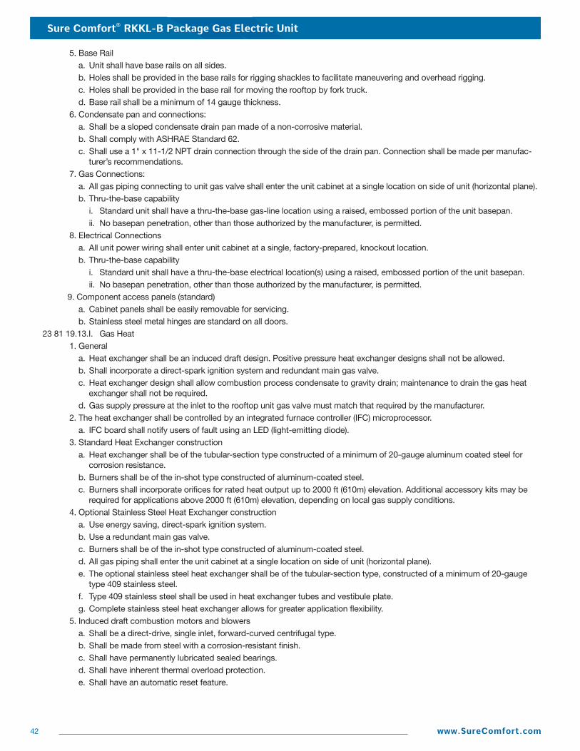
Sure Comfort® RKKL-B Package Gas Electric Unit
42 www.SureComfort.com
5. Base Rail a. Unit shall have base rails on all sides. b. Holes shall be provided in the base rails for rigging shackles to facilitate maneuvering and overhead rigging. c. Holes shall be provided in the base rail for moving the rooftop by fork truck. d. Base rail shall be a minimum of 14 gauge thickness. 6. Condensate pan and connections: a. Shall be a sloped condensate drain pan made of a non-corrosive material. b. Shall comply with ASHRAE Standard 62. c. Shall use a 1" x 11-1/2 NPT drain connection through the side of the drain pan. Connection shall be made per manufac-
turer’s recommendations. 7. Gas Connections: a. All gas piping connecting to unit gas valve shall enter the unit cabinet at a single location on side of unit (horizontal plane). b. Thru-the-base capability i. Standard unit shall have a thru-the-base gas-line location using a raised, embossed portion of the unit basepan. ii. No basepan penetration, other than those authorized by the manufacturer, is permitted. 8. Electrical Connections a. All unit power wiring shall enter unit cabinet at a single, factory-prepared, knockout location. b. Thru-the-base capability i. Standard unit shall have a thru-the-base electrical location(s) using a raised, embossed portion of the unit basepan. ii. No basepan penetration, other than those authorized by the manufacturer, is permitted. 9. Component access panels (standard) a. Cabinet panels shall be easily removable for servicing. b. Stainless steel metal hinges are standard on all doors.23 81 19.13.I. Gas Heat 1. General a. Heat exchanger shall be an induced draft design. Positive pressure heat exchanger designs shall not be allowed. b. Shall incorporate a direct-spark ignition system and redundant main gas valve. c. Heat exchanger design shall allow combustion process condensate to gravity drain; maintenance to drain the gas heat
exchanger shall not be required. d. Gas supply pressure at the inlet to the rooftop unit gas valve must match that required by the manufacturer. 2. The heat exchanger shall be controlled by an integrated furnace controller (IFC) microprocessor. a. IFC board shall notify users of fault using an LED (light-emitting diode). 3. Standard Heat Exchanger construction a. Heat exchanger shall be of the tubular-section type constructed of a minimum of 20-gauge aluminum coated steel for
corrosion resistance. b. Burners shall be of the in-shot type constructed of aluminum-coated steel. c. Burners shall incorporate orifices for rated heat output up to 2000 ft (610m) elevation. Additional accessory kits may be
required for applications above 2000 ft (610m) elevation, depending on local gas supply conditions. 4. Optional Stainless Steel Heat Exchanger construction a. Use energy saving, direct-spark ignition system. b. Use a redundant main gas valve. c. Burners shall be of the in-shot type constructed of aluminum-coated steel. d. All gas piping shall enter the unit cabinet at a single location on side of unit (horizontal plane). e. The optional stainless steel heat exchanger shall be of the tubular-section type, constructed of a minimum of 20-gauge
type 409 stainless steel. f. Type 409 stainless steel shall be used in heat exchanger tubes and vestibule plate. g. Complete stainless steel heat exchanger allows for greater application flexibility. 5. Induced draft combustion motors and blowers a. Shall be a direct-drive, single inlet, forward-curved centrifugal type. b. Shall be made from steel with a corrosion-resistant finish. c. Shall have permanently lubricated sealed bearings. d. Shall have inherent thermal overload protection. e. Shall have an automatic reset feature.
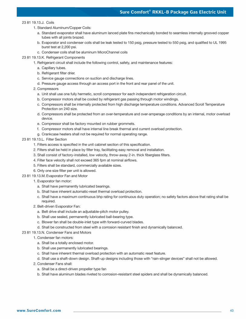
Sure Comfort® RKKL-B Package Gas Electric Unit
43www.SureComfort.com
23 81 19.13.J. Coils 1. Standard Aluminum/Copper Coils: a. Standard evaporator shall have aluminum lanced plate fins mechanically bonded to seamless internally grooved copper
tubes with all joints brazed. b. Evaporator and condenser coils shall be leak tested to 150 psig, pressure tested to 550 psig, and qualified to UL 1995
burst test at 2,200 psi. c. Condenser coils shall be aluminum MicroChannel coils23 81 19.13.K. Refrigerant Components 1. Refrigerant circuit shall include the following control, safety, and maintenance features: a. Capillary tubes. b. Refrigerant filter drier. c. Service gauge connections on suction and discharge lines. d. Pressure gauge access through an access port in the front and rear panel of the unit. 2. Compressors a. Unit shall use one fully hermetic, scroll compressor for each independent refrigeration circuit. b. Compressor motors shall be cooled by refrigerant gas passing through motor windings. c. Compressors shall be internally protected from high discharge temperature conditions. Advanced Scroll Temperature
Protection on 240 size. d. Compressors shall be protected from an over-temperature and over-amperage conditions by an internal, motor overload
device. e. Compressor shall be factory mounted on rubber grommets. f. Compressor motors shall have internal line break thermal and current overload protection. g. Crankcase heaters shall not be required for normal operating range.23 81 19.13.L. Filter Section 1. Filters access is specified in the unit cabinet section of this specification. 2. Filters shall be held in place by filter tray, facilitating easy removal and installation. 3. Shall consist of factory-installed, low velocity, throw-away 2-in. thick fiberglass filters. 4. Filter face velocity shall not exceed 365 fpm at nominal airflows. 5. Filters shall be standard, commercially available sizes. 6. Only one size filter per unit is allowed.23 81 19.13.M. Evaporator Fan and Motor 1. Evaporator fan motor: a. Shall have permanently lubricated bearings. b. Shall have inherent automatic-reset thermal overload protection. c. Shall have a maximum continuous bhp rating for continuous duty operation; no safety factors above that rating shall be
required. 2. Belt-driven Evaporator Fan: a. Belt drive shall include an adjustable-pitch motor pulley. b. Shall use sealed, permanently lubricated ball-bearing type. c. Blower fan shall be double-inlet type with forward-curved blades. d. Shall be constructed from steel with a corrosion resistant finish and dynamically balanced.23 81 19.13.N. Condenser Fans and Motors 1. Condenser fan motors: a. Shall be a totally enclosed motor. b. Shall use permanently lubricated bearings. c. Shall have inherent thermal overload protection with an automatic reset feature. d. Shall use a shaft-down design. Shaft-up designs including those with “rain-slinger devices” shall not be allowed. 2. Condenser Fans shall: a. Shall be a direct-driven propeller type fan b. Shall have aluminum blades riveted to corrosion-resistant steel spiders and shall be dynamically balanced.

Sure Comfort® RKKL-B Package Gas Electric Unit
44 www.SureComfort.com
23 81 19.13.O. Special Features 1. Integrated Economizers: a. Integrated, gear-driven parallel modulating blade design type capable of simultaneous economizer and compressor
operation. b. Independent modules for vertical or horizontal return configurations shall be available. Vertical return modules shall be
available as a factory installed option. c. Damper blades shall be galvanized steel with metal gears. Plastic or composite blades on intake or return shall not be
acceptable. d. Shall include all hardware and controls to provide free cooling with outdoor air when temperature and/or humidity are
below setpoints. e. Shall be equipped with gear driven dampers for both the outdoor ventilation air and the return air for positive air stream
control. f. Shall be capable of introducing up to 100% outdoor air. g. Shall be equipped with a barometric relief damper capable of relieving up to 100% return air. The barometric relief damper shall include seals, hardware and hoods to relieve building pressure. Damper shall gravity close upon unit shut down. h. Shall be designed to close damper(s) during loss-of-power situations with spring return built into motor. i. An outdoor single-enthalpy sensor shall be provided as standard. Outdoor air enthalpy set point shall be adjustable and
shall range from the enthalpy equivalent of 63°F @ 50% rh to 73°F @ 50% rh. Additional sensor options shall be availableas accessories.
j. The economizer controller shall also provide control of an accessory power exhaust unit function. Factory set at 70%,with a range of 0% to 100%.
k. The economizer shall maintain minimum airflow into the building during occupied period and provide design ventilationrate for full occupancy. A remote potentiometer may be used to override the damper set point.
l. Economizer controller shall accept a 2-10Vdc CO2 sensor input for IAQ/DCV control. In this mode, dampers shall modu-late the outdoor-air damper to provide ventilation based on the sensor input.
m.Actuator shall be direct coupled to economizer gear. No linkage arms or control rods shall be acceptable. n. Economizer controller shall provide indications when in free cooling mode, in the DCV mode, or the exhaust fan contact is
closed. 2. Two-Position Damper a. Damper shall be a Two-Position Damper. Damper travel shall be from the full closed position to the field adjustable %-
open setpoint. b. Damper shall include adjustable damper travel from 25% to 100% (full open). c. Damper shall include single or dual blade, gear driven damper and actuator motor. d. Actuator shall be direct coupled to economizer gear. No linkage arms or control rods shall be acceptable. e. Damper will admit up to 100% outdoor air for applicable rooftop units. f. Damper shall close upon indoor (evaporator) fan shutoff and/or loss of power. g. The damper actuator shall plug into the rooftop unit’s wiring harness plug. No hard wiring shall be required. h. Outside air hood shall include aluminum water entrainment filter. 3. Manual damper a. Manual damper package shall consist of damper, air inlet screen, and rain hood which can be preset to admit up to 50%
outdoor air for year round ventilation. 4. Head Pressure Control Package a. Controller shall control coil head pressure by condenser-fan cycling. 5. Liquid Propane (LP) Conversion Kit a. Package shall contain all the necessary hardware and instructions to convert a standard natural gas unit for use with
liquefied propane, up to 2000 ft (610m) elevation. 6. Unit-Mounted, Non-Fused Disconnect Switch: a. Switch shall be factory-installed, internally mounted. b. National Electric Code (NEC) and UL approved non-fused switch shall provide unit power shutoff. c. Shall be accessible from outside the unit. d. Shall provide local shutdown and lockout capability.

Sure Comfort® RKKL-B Package Gas Electric Unit
45www.SureComfort.com
e. Non-Powered convenience outlet. f. Outlet shall be powered from a separate 115-120v power source. g. A transformer shall not be included. h. Outlet shall be field-installed and internally mounted with easily accessible 115-v female receptacle. i. Outlet shall include 15 amp GFI receptacle. j. Outlet shall be accessible from outside the unit. 7. Flue Discharge Deflector: a. Flue discharge deflector shall direct unit exhaust vertically instead of horizontally. b. Deflector shall be defined as a “natural draft” device by the National Fuel and Gas (NFG) code. 8. Thru-the-Base Connectors: a. Kits shall provide connectors to permit gas and electrical connections to be brought to the unit through the unit basepan. 9. Propeller Power Exhaust: a. Power exhaust shall be used in conjunction with an integrated economizer. b. Independent modules for vertical or horizontal return configurations shall be available. c. Horizontal power exhaust is shall be mounted in return ductwork. d. Power exhaust shall be controlled by economizer controller operation. Exhaust fans shall be energized when dampers
open past the 0-100% adjustable setpoint on the economizer control. 10. Roof Curbs (Vertical): a. Full perimeter roof curb with exhaust capability providing separate airstreams for energy recovery from the exhaust air
without supply air contamination. b. Formed galvanized steel with wood nailer strip and shall be capable of supporting entire unit weight. c. Permits installation and securing of ductwork to curb prior to mounting unit on the curb. 11. Universal Gas Conversion Kit: a. Package shall contain all the necessary hardware and instructions to convert a standard natural gas unit to operate from
2000-7000 ft (610 to 2134m) elevation with natural gas or from 0-7000 ft (90-2134m) elevation with liquefied propane. 12. Outdoor Air Enthalpy Sensor: a. The outdoor air enthalpy sensor shall be used to provide single enthalpy control. When used in conjunction with a return
air enthalpy sensor, the unit will provide differential enthalpy control. The sensor allows the unit to determine if outside airis suitable for free cooling.
13. Return Air Enthalpy Sensor: a. The return air enthalpy sensor shall be used in conjunction with an outdoor air enthalpy sensor to provide differential
enthalpy control. 14. Indoor Air Quality (CO2) Sensor: a. Shall be able to provide demand ventilation indoor air quality (IAQ) control. b. The IAQ sensor shall be available in wall mount with LED display. The set point shall have adjustment capability. 15. Smoke detectors: a. Shall be a Four-Wire Controller and Detector. b. Shall be environmental compensated with differential sensing for reliable, stable, and drift-free sensitivity. c. Shall use magnet-activated test/reset sensor switches. d. Shall have tool-less connection terminal access. e. Shall have a recessed momentary switch for testing and resetting the detector. f. Controller shall include: i. One set of normally open alarm initiation contacts for connection to an initiating device circuit on a fire alarm control
panel ii. Two Form-C auxiliary alarm relays for interface with rooftop unit or other equipment. iii. One Form-C supervision (trouble) relay to control the operation of the Trouble LED on a remote test/reset station. iv. Capable of direct connection to two individual detector modules. v. Can be wired to up to 14 other duct smoke detectors for multiple fan shutdown applications.

Sure Comfort® RKKL-B Package Gas Electric Unit
46 www.SureComfort.com

Sure Comfort® RKKL-B Package Gas Electric Unit
47www.SureComfort.com
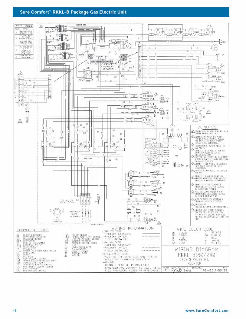
Sure Comfort® RKKL-B Package Gas Electric Unit
48 www.SureComfort.com
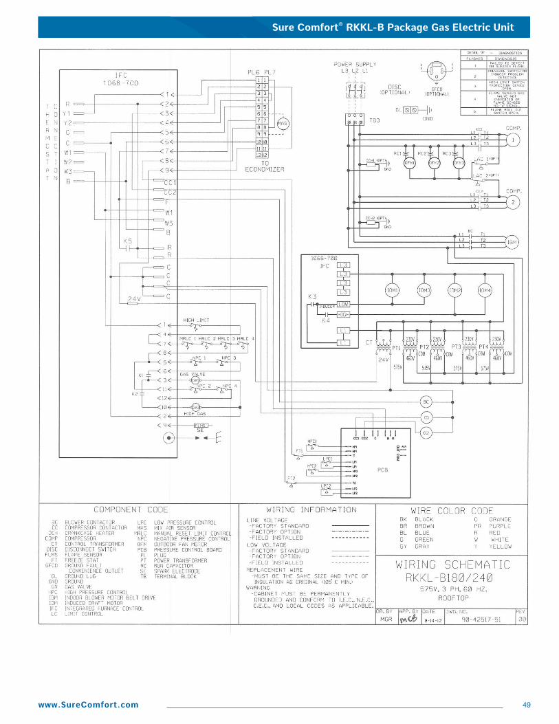
Sure Comfort® RKKL-B Package Gas Electric Unit
49www.SureComfort.com
Sure Comfort® RKKL-B Package Gas Electric Unit
50 www.SureComfort.com
GENERAL TERMS OF LIMITED WARRANTY*
BEFORE PURCHASING THIS APPLIANCE, READ IMPORTANT ENERGY COST AND EFFICIENCY INFORMATION AVAILABLE FROMYOUR RETAILER.
Compressor 3 Phase, Commercial Applications ..................Five (5) YearsParts 3 Phase, Commercial Applications....................One (1) Year
*For complete details of the Limited and Conditional Warranties, includingapplicable terms and conditions, contact your local contractor or theManufacturer for a copy of the product warranty certificate.
Stainless Steel Heat Exchanger 3 Phase, Commercial Applications ...........Twenty (20) YearsStandard Heat Exchanger 3 Phase, Commercial Applications .................Ten (10) Years
Sure Comfort® will furnish a replacement for any part of this product which fails in normal use and service within the applicableperiods stated, in accordance with the terms of the limited warranty.
Sure Comfort® RKKL-B Package Gas Electric Unit
51www.SureComfort.com
10/16 QG FORM NO. RSC-859
Before proceeding with installation, referto installation instructions packagedwith each model, as well as complyingwith all Federal, State, Provincial, andLocal codes, regulations, and practices.
Sure Comfort®
P.O. Box 17010, Fort Smith, AR 72917