rknl 13 seer (3-5 tons) series rkpl 14 seer (3-5 ... -...
TRANSCRIPT

92-23577-75-00
(14 SEER ONLY)
INSTALLATION INSTRUCTIONSPackage Gas Electric FeaturingEarth-Friendly R-410A RefrigerantRKNL 13 SEER (3-5 TONS) SERIESRKPL 14 SEER (3-5 TONS) SERIES
r e f r i g e r a n t
2
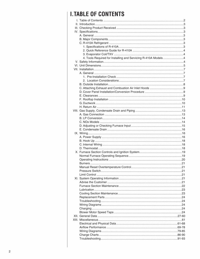
I.TABLE OF CONTENTSI. Table of Contents ..................................................................................................2II. Introduction ............................................................................................................3III. Checking Product Received ..................................................................................3IV. Specifications.........................................................................................................3
A. General .............................................................................................................3B. Major Components............................................................................................3C. R-410A Refrigerant ...........................................................................................3
1. Specifications of R-410A...............................................................................32. Quick Reference Guide for R-410A ..............................................................43. Evaporator Coil/TXV .....................................................................................44. Tools Required for Installing and Servicing R-410A Models.........................4
V. Safety Information..................................................................................................4VI. Unit Dimensions.....................................................................................................5VII. Installation..............................................................................................................7
A. General .............................................................................................................71. Pre-Installation Check ..................................................................................72. Location Considerations...............................................................................7
B. Outside Installation............................................................................................8C. Attaching Exhaust and Combustion Air Inlet Hoods .........................................9D. Cover Panel Installation/Conversion Procedure ...............................................9E. Clearances ........................................................................................................9F. Rooftop Installation .........................................................................................10G. Ductwork .........................................................................................................10H. Return Air ........................................................................................................11
VIII. Gas Supply, Condensate Drain and Piping .........................................................13A. Gas Connection ..............................................................................................13B. LP Conversion.................................................................................................14C. NOx Models ....................................................................................................14D. Adjusting or Checking Furnace Input ..............................................................15E. Condensate Drain ...........................................................................................16
IX. Wiring...................................................................................................................16A. Power Supply ..................................................................................................16B. Hook Up ..........................................................................................................18C. Internal Wiring .................................................................................................18D. Thermostat ......................................................................................................18
X. Furnace Section Controls and Ignition System....................................................19Normal Furnace Operating Sequence.................................................................19Operating Instructions .........................................................................................20Burners ................................................................................................................21Manual Reset Overtemperature Control..............................................................21Pressure Switch...................................................................................................21Limit Control ........................................................................................................21
XI. System Operating Information .............................................................................21Advise the Customer ...........................................................................................21Furnace Section Maintenance.............................................................................22Lubrication ...........................................................................................................23Cooling Section Maintenance..............................................................................23Replacement Parts ..............................................................................................24Troubleshooting...................................................................................................24Wiring Diagrams..................................................................................................24Charging ..............................................................................................................24Blower Motor Speed Taps ...................................................................................24
XII. General Data ..................................................................................................27-60XIII. Miscellaneous ......................................................................................................61
Electrical and Physical Data...........................................................................61-68Airflow Performance .......................................................................................69-78Wiring Diagrams.............................................................................................79-85Charge Charts ................................................................................................86-90Troubleshooting..............................................................................................91-93

3
II. INTRODUCTIONThis booklet contains the installation and operating instructions for your combination gasheating/electric cooling unit. There are some precautions that should be taken to derivemaximum satisfaction from it. Improper installation can result in unsatisfactory operationor dangerous conditions.
Read this booklet and any instructions packaged with separate equipment required tomake up the system prior to installation. Give this booklet to the owner and explain itsprovisions. The owner should retain this booklet for future reference.
III. CHECKING PRODUCT RECEIVEDUpon receiving the unit, inspect it for any damage from shipment. Claims for damage,either shipping or concealed, should be filed immediately with the shipping company.IMPORTANT: Check the unit model number, heating size, electrical characteristics, andaccessories to determine if they are correct.
IV. SPECIFICATIONSA. GENERALThe Combination Gas Heating/Electric Cooling Rooftop is available in 80,000, 100,000,120,000 and 135,000 BTU/Hr. heating inputs and cooling capacities of 3, 31⁄2, 4, and 5nominal tons of cooling. Units are convertible from bottom supply and return to side sup-ply and return by relocation of supply and return air access panels. See cover installa-tion detail.
The units are weatherized for mounting outside of the building.
The information on the rating plate is in compliance with the FTC and DOE rating for sin-gle phase units. The following information is for three phase units which are not coveredunder the DOE certification program.
1. The energy consumption of the ignition system used with this unit is 9 watts.
2. The efficiency rating of this unit is a product thermal efficiency rating determinedunder continuous operating conditions independent of any installed system.
B. MAJOR COMPONENTSThe unit includes a hermetically-sealed refrigerating system (consisting of a scroll com-pressor, condenser coil, evaporator coil with thermostatic expansion valve), a circulationair blower, a condenser fan, a heat exchanger assembly, gas burner and control assem-bly, combustion air motor and fan, and all necessary internal electrical wiring. The cool-ing system of these units is factory-evacuated, charged with R-410A refrigerant and per-formance tested. Refrigerant amount and type are indicated on rating plate.
C. R410A REFRIGERANTAll units are factory charged with R-410A refrigerant.
1. Specification of R-410A:Application: R-410A is not a drop-in replacement for R-22; equipment designs mustaccommodate its higher pressures. It cannot be retrofitted into R-22 units.
Pressure: The pressure of R-410A is approximately 60% (1.6 times) greater than R-22. Recovery and recycle equipment, pumps, hoses and the like need to have designpressure ratings appropriate for R-410A. Manifold sets need to range up to 800 psighigh-side and 250 psig low-side with a 550 psig low-side retard. Hoses need to have aservice pressure rating of 800 psig. Recovery cylinders need to have a 400 psig servicepressure rating. DOT 4BA400 or DOT BW400.
Combustibility: At pressures above 1 atmosphere, mixture of R-410A and air canbecome combustible. R-410A and air should never be mixed in tanks or supply
! WARNINGTHE MANUFACTURER’S WARRAN-TY DOES NOT COVER ANY DAM-AGE OR DEFECT TO THE AIR CON-DITIONER CAUSED BY THEATTACHMENT OR USE OF ANYCOMPONENTS, ACCESSORIES ORDEVICES (OTHER THAN THOSEAUTHORIZED BY THE MANUFAC-TURER) INTO, ONTO OR IN CON-JUNCTION WITH THE AIR CONDI-TIONER. YOU SHOULD BE AWARETHAT THE USE OF UNAUTHO-RIZED COMPONENTS, ACCES-SORIES OR DEVICES MAYADVERSELY AFFECT THE OPERA-TION OF THE AIR CONDITIONERAND MAY ALSO ENDANGER LIFEAND PROPERTY. THE MANUFAC-TURER DISCLAIMS ANY RESPON-SIBILITY FOR SUCH LOSS ORINJURY RESULTING FROM THEUSE OF SUCH UNAUTHORIZEDCOMPONENTS, ACCESSORIES ORDEVICES.
! WARNINGUNITS ARE NOT DESIGN CERTIFIED TO BE INSTALLED INSIDE THE STRUC-TURE. DOING SO CAN CAUSE INADEQUATE UNIT PERFORMANCE AS WELLAS PROPERTY DAMAGE AND CARBON MONOXIDE POISONING RESULTINGIN PERSONAL INJURY OR DEATH.
Recognize this symbol as an indi-cat ion of Important SafetyInformation!
!
! WARNINGINSTALL THIS UNIT ONLY IN ALOCATION AND POSITION ASSPECIFIED IN THE LOCATIONREQUIREMENTS AND CONSIDER-ATIONS SECTION OF THESEINSTRUCTIONS. PROVIDE ADE-QUATE COMBUSTION AND VENTI-LATION AIR TO THE UNIT SPACEAS SPECIFIED IN THE VENTINGSECTION OF THESE INSTRUC-TIONS.
! WARNINGPROVIDE ADEQUATE COMBUS-TION AND VENTILATION AIR TOTHE UNIT SPACE AS SPECIFIED INTHE COMBUSTION AND VENTILA-TION AIR SECTION OF THESEINSTRUCTIONS.

4
lines, or be allowed to accumulate in storage tanks. Leak checking should neverbe done with a mixture of R-410A and air. Leak checking can be performed safelywith nitrogen or a mixture of R-410A and nitrogen.
2. Quick Reference Guide For R-410A• R-410A refrigerant operates at approximately 60% higher pressure (1.6 times) than R-
22. Ensure that servicing equipment is designed to operate with R-410A.
• R-410A refrigerant cylinders are pink.
• R-410A, as with other HFC’s is only compatible with POE oils.
• Vacuum pumps will not remove moisture from POE oil.
• R-410A systems are to be charged with liquid refrigerants. Prior to March 1999, R-410A refrigerant cylinders had a dip tube. These cylinders should be kept upright forequipment charging. Post March 1999 cylinders do not have a dip tube and shouldbe inverted to ensure liquid charging of the equipment.
• Do not install a suction line filter drier in the liquid line.
• A liquid line filter drier is standard on every unit.
• Desiccant (drying agent) must be compatible for POE oils and R-410A
3. Evaporator Coil / TXVThe thermostatic expansion valve is specifically designed to operate with R-410A. DONOT use an R-22 TXV. The existing evaporator must be replaced with the factoryspecified TXV evaporator specifically designed for R-410A.
4. Tools Required For Installing & Servicing R-410A ModelsManifold Sets:
-Up to 800 PSIG High side-Up to 250 PSIG Low Side-550 PSIG Low Side Retard
Manifold Hoses:-Service Pressure Rating of 800 PSIG
Recovery Cylinders:-400 PSIG Pressure Rating-Dept. of Transportation 4BA400 or BW400
V. SAFETY INFORMATION
! CAUTIONR-410A systems operate at higher pressures than R-22 systems. Do not useR-22 service equipment or components on R-410A equipment.
! WARNINGUSE ONLY WITH TYPE OF GAS APPROVED FOR THIS UNIT. REFER TO THEUNIT RATING PLATE.

5
FIGURE 1BOTTOM VIEW
FIGURE 2CABINET DIMENSIONS AND ACCESS LOCATIONS
VI. UNIT DIMENSIONSFOR CLEARANCESSEE FIGURE 7.
IMPORTANT: THIS UNITMUST BE MOUNTEDLEVEL IN BOTH DIREC-TIONS TO ALLOW WATERTO DRAIN FROM THE CON-DENSER SECTION ANDCONDENSATE PAN.
I316
I281

6
FIGURE 3CABINET DIMENSIONS AND ACCESS LOCATIONS
FIGURE 4SUPPLY AND RETURN DIMENSIONS
I282
I288

7
VII. INSTALLATIONA. GENERALInstall this unit in accordance with The American National Standard Z223.1-latest editionbooklet entitled “National Fuel Gas Code,” and the requirements or codes of the localutility or other authority having jurisdiction.
Additional helpful publications available from the “National Fire Protection Association”are: NFPA-90A - Installation of Air Conditioning and Ventilating Systems 1985 or latestedition. NFPA-90B - Warm Air Heating and Air Conditioning Systems 1984.
These publications are available from:
National Fire Protection Association, Inc.1 Batterymarch ParkQuincy, MA 02169-7471www.nfpa.org
1. PRE-INSTALLATION CHECK-POINTS — Before attempting any installation, care-fully consider the following points:
Structural strength of supporting members(Rooftop Installation)
Clearances and provision for servicingPower supply and wiringGas supply and pipingAir duct connections and sizingDrain facilities and connectionsLocation for minimum noise and
vibration - away from bedroomwindows
2. LOCATION CONSIDERATIONS
The metal parts of this unit may be subject to rust or deterioration in adverse envi-ronmental conditions. This oxidation could shorten the equipment’s useful life. Saltspray, fog or mist in seacoast areas, sulphur or chlorine from lawn watering systems,and various chemical contaminants from industries such as paper mills and petrole-um refineries are especially corrosive.
If the unit is to be installed in an area where contaminants are likely to be aproblem, give special attention to the equipment location and exposure.
1. Avoid having lawn sprinkler heads spray directly on the unit cabinet.
2. In coastal areas locate the unit on the side of the building away from the water-front.
3. Shielding by a fence or shrubs may give some protection.
1. Frequent washing of the cabinet, fan blade and coil with fresh water will removemost of the salt or other contaminants that build up on the unit.
2. Regular cleaning and waxing of the cabinet with a good automobile polish will pro-vide some protection.
3. A good liquid cleaner may be used several times a year to remove matter that willnot wash off with water.
Several different types of protective coatings are offered in some areas. These coatingsmay provide some benefit, but the effectiveness of such coating materials cannot be ver-ified by the equipment manufacturer.
The best protection is frequent cleaning, maintenance and minimal exposure tocontaminants.
! WARNINGDISCONNECT ALL POWER TO UNIT BEFORE STARTING MAINTENANCE.FAILURE TO DO SO CAN CAUSE ELECTRICAL SHOCK RESULTING IN PER-SONAL INJURY OR DEATH. REGULAR MAINTENANCE WILL REDUCE THEBUILDUP OF CONTAMINANTS AND HELP TO PROTECT THE UNIT’S FINISH.
! WARNINGALWAYS INSTALL UNIT TO OPER-ATE WITHIN THE UNIT'S INTEND-ED TEMPERATURE-RISE RANGEWITH A DUCT SYSTEM WHICHHAS AN EXTERNAL STATIC PRES-SURE WITHIN THE ALLOWABLERANGE, AS SPECIFIED IN DUCT-ING SECTION OF THESE INSTRUC-TIONS. SEE ALSO UNIT RATINGPLATE.
! WARNINGWHEN A UNIT IS INSTALLED SOTHAT SUPPLY DUCTS CARRY AIRCIRCULATED BY THE UNIT TOAREAS OUTSIDE THE SPACE CON-TAINING THE UNIT, THE RETURNAIR SHALL ALSO BE HANDLED BYDUCT(S) SEALED TO THE UNITCASING AND TERMINATING OUT-SIDE THE SPACE CONTAININGTHE UNIT.
! WARNINGNEVER TEST FOR GAS LEAKSWITH AN OPEN FLAME. USE ACOMMERCIALLY AVAILABLE SOAPSOLUTION MADE SPECIFICALLYFOR THE DETECTION OF LEAKSTO CHECK ALL CONNECTIONS, ASSPECIFIED IN GAS SUPPLY ANDPIPING SECTION OF THESEINSTRUCTIONS.

8
B. OUTSIDE SLAB INSTALLATION
(Typical outdoor slab installation is shown in Figure 5.)
1. Select a location where external water drainage cannot collect around unit.
2. Provide a level slab sufficiently high enough above grade to prevent surface waterfrom entering the unit
3. The location of the unit should be such as to provide proper access for inspectionand servicing as shown in Figure 7.
4. Locate unit where operating sounds will not disturb owner or neighbors.
5. Locate unit so roof runoff water does not pour directly on the unit. Provide gutter orother shielding at roof level. Do not locate unit in an area where excessive snowdrifting may occur or accumulate.
6. Where snowfall is anticipated, the height of the unit above the ground level must beconsidered. Mount unit high enough to be above anticipated maximum area snowfalland to allow combustion air to enter the combustion air inlet.
7. Select an area which will keep the areas of the vent, air intake, and A/C condenserfins free and clear of obstructions such as weeds, shrubs, vines, snow, etc. Informthe user accordingly.
8. Remove compressor shipping supports (if so equipped) after installation.
FIGURE 5OUTSIDE SLAB INSTALLATION. CLOSET DISTRIBUTION SYSTEM. SLAB FLOOR CONSTRUCTION.
I298
! WARNINGTHIS UNIT MAY BE USED TO HEATTHE BUILDING OR STRUCTUREDURING CONSTRUCTION IF THEFOLLOWING INSTALLATIONREQUIREMENTS ARE MET.INSTALLATION MUST COMPLYWITH ALL INSTALLATIONINSTRUCTIONS INCLUDING:
• PROPER VENT INSTALLATION;
• FURNACE OPERATING UNDERTHERMOSTATIC CONTROL;
• RETURN AIR DUCT SEALED TOTHE FURNACE;
• AIR FILTERS IN PLACE;
• SET FURNACE INPUT RATE ANDTEMPERATURE RISE PER RAT-ING PLATE MARKING;
• MEANS OF PROVIDING OUT-DOOR AIR REQUIRED FOR COM-BUSTION;
• RETURN AIR TEMPERATUREMAINTAINED BETWEEN 55°F(13°C) AND 80°F (27°C); AND
• INSTALLATION OF EXHAUSTAND COMBUSTION AIR INLETHOODS COMPLETED;
• CLEAN FURNACE, DUCT WORKAND COMPONENTS UPON SUB-STANTIAL COMPLETION OF THECONSTRUCTION PROCESS, ANDVERIFY FURNACE OPERATINGCONDITIONS INCLUDING IGNI-TION, INPUT RATE, TEMPERA-TURE RISE AND VENTING,ACCORDING TO THE INSTRUC-TIONS.
! WARNINGTHESE UNITS ARE DESIGNED CERTIFIED FOR OUTDOOR INSTALLATIONONLY. INSTALLATION INSIDE ANY PART OF A STRUCTURE CAN RESULT ININADEQUATE UNIT PERFORMANCE AS WELL AS PROPERTY DAMAGE.INSTALLATION INSIDE CAN ALSO CAUSE RECIRCULATION OF FLUE PROD-UCTS INTO THE CONDITIONED SPACE RESULTING IN PERSONAL INJURYOR DEATH.
9
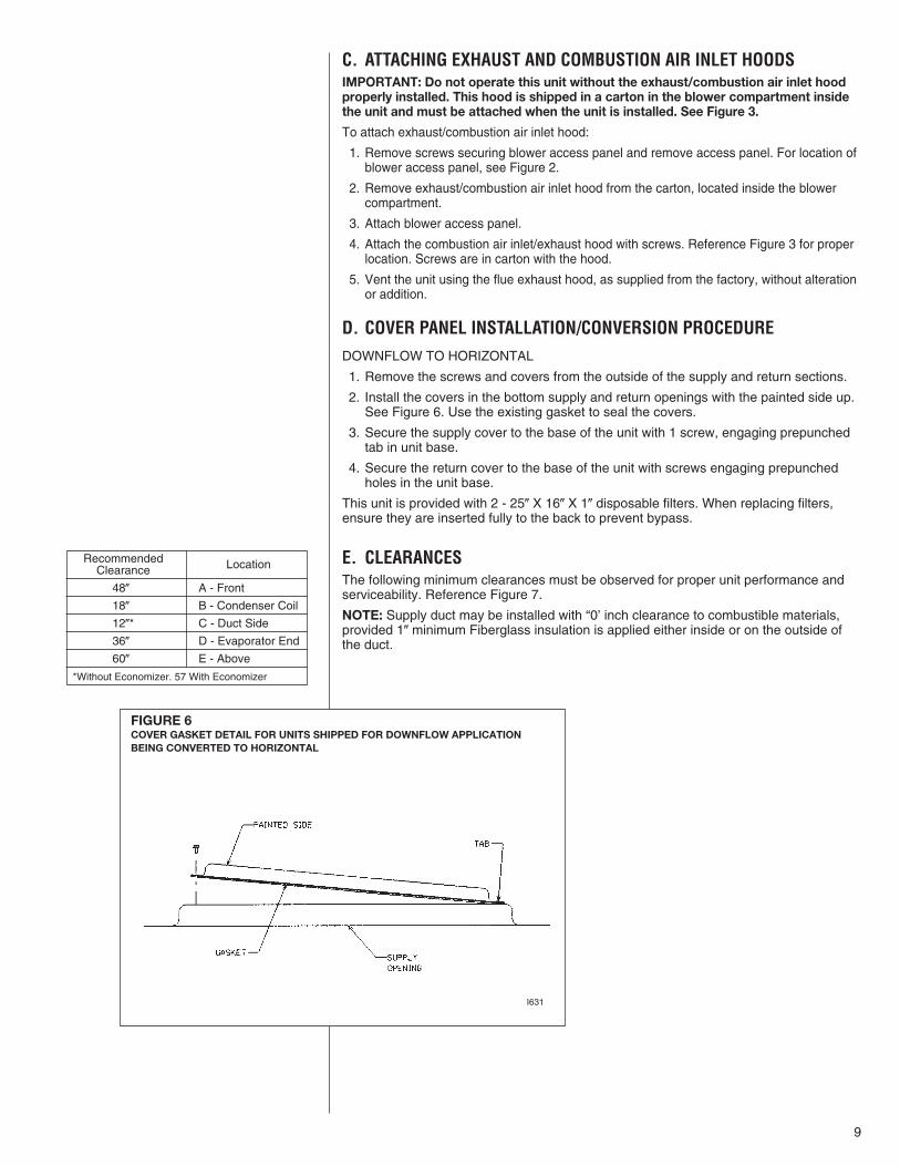
RecommendedClearance Location
48� A - Front
18� B - Condenser Coil
12�* C - Duct Side
36� D - Evaporator End
60� E - Above
*Without Economizer. 57 With Economizer
C. ATTACHING EXHAUST AND COMBUSTION AIR INLET HOODSIMPORTANT: Do not operate this unit without the exhaust/combustion air inlet hoodproperly installed. This hood is shipped in a carton in the blower compartment insidethe unit and must be attached when the unit is installed. See Figure 3.
To attach exhaust/combustion air inlet hood:
1. Remove screws securing blower access panel and remove access panel. For location ofblower access panel, see Figure 2.
2. Remove exhaust/combustion air inlet hood from the carton, located inside the blowercompartment.
3. Attach blower access panel.
4. Attach the combustion air inlet/exhaust hood with screws. Reference Figure 3 for properlocation. Screws are in carton with the hood.
5. Vent the unit using the flue exhaust hood, as supplied from the factory, without alterationor addition.
D. COVER PANEL INSTALLATION/CONVERSION PROCEDUREDOWNFLOW TO HORIZONTAL
1. Remove the screws and covers from the outside of the supply and return sections.
2. Install the covers in the bottom supply and return openings with the painted side up.See Figure 6. Use the existing gasket to seal the covers.
3. Secure the supply cover to the base of the unit with 1 screw, engaging prepunchedtab in unit base.
4. Secure the return cover to the base of the unit with screws engaging prepunchedholes in the unit base.
This unit is provided with 2 - 25� X 16� X 1� disposable filters. When replacing filters,ensure they are inserted fully to the back to prevent bypass.
E. CLEARANCESThe following minimum clearances must be observed for proper unit performance andserviceability. Reference Figure 7.
NOTE: Supply duct may be installed with “0’ inch clearance to combustible materials,provided 1� minimum Fiberglass insulation is applied either inside or on the outside ofthe duct.
FIGURE 6COVER GASKET DETAIL FOR UNITS SHIPPED FOR DOWNFLOW APPLICATIONBEING CONVERTED TO HORIZONTAL
I631

10
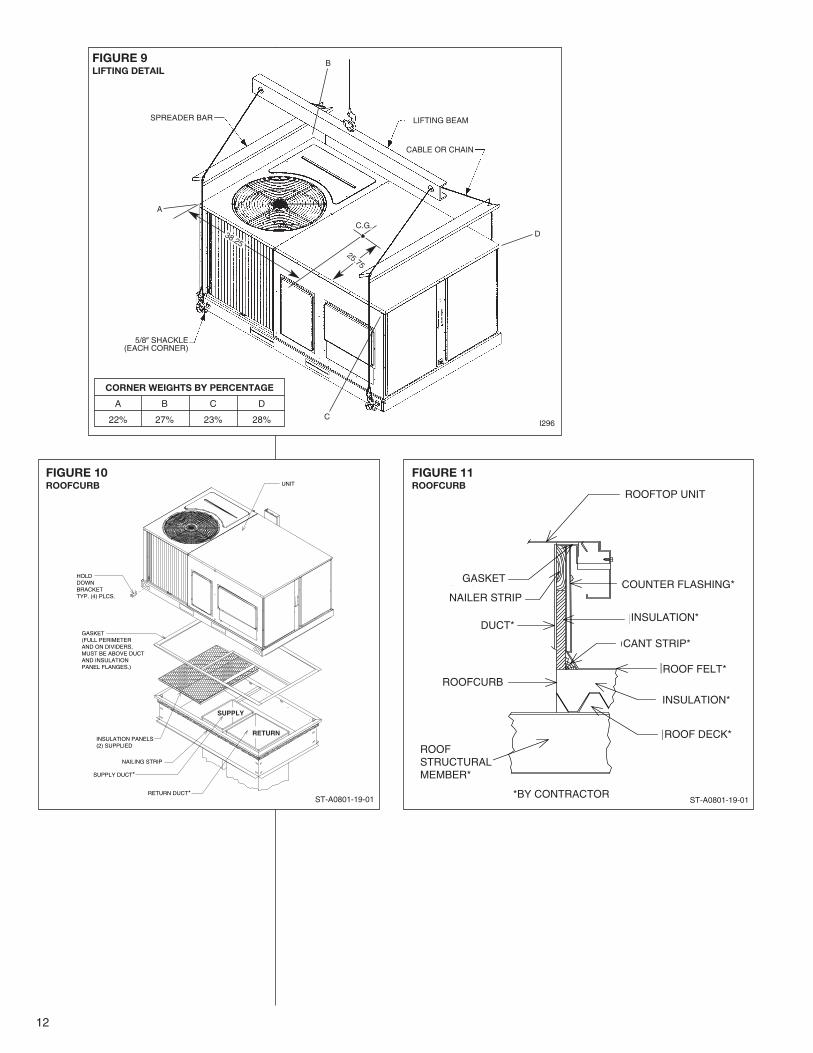
F. ROOFTOP INSTALLATION1. Before locating the unit on the roof, make sure that the roof structure is adequate to
support the weight involved. (See Electrical & Physical Tables in this manual.) THISIS VERY IMPORTANT AND THE INSTALLER’S RESPONSIBILITY.
2. For rigging and roofcurb details, see Figures 8, 9, 10 and 11.
3. The location of the unit on the roof should be such as to provide proper access forinspection and servicing.
4. Remove compressor shipping supports (if so equipped) after installation.
IMPORTANT: If unit will not be put into service immediately, block off supply and returnair openings to prevent excessive condensation.
G. DUCTWORKThe installing contractor should fabricate ductwork in accordance with local codes. Useindustry manuals as a guide when sizing and designing the duct system. Contact AirConditioning Contractors of America, 2800 Shirlington Road, Suite 300, Arlington, VA22206, http://www.acca.org.
FIGURE 7CLEARANCES
I297
! WARNINGDO NOT, UNDER ANY CIRCUMSTANCES, CONNECT RETURN DUCTWORKTO ANY OTHER HEAT PRODUCING DEVICE SUCH AS FIREPLACE INSERT,STOVE, ETC. UNAUTHORIZED USE OF SUCH DEVICES MAY RESULT IN FIRE,CARBON MONOXIDE POISONING, EXPLOSION, PERSONAL INJURY, PROP-ERTY DAMAGE OR DEATH.

11
Place the unit as close to the conditioned space as possible allowing clearances as indi-cated. Run ducts as directly as possible to supply and return outlets. Use of non-flam-mable weatherproof flexible connectors on both supply and return connections at unit toreduce noise transmission is recommended.
On ductwork exposed to outside temperature and humidity, use a minimum of 2� ofinsulation and a vapor barrier. Distribution system in attic, furred space or crawl spaceshould be insulated with at least 2� of insulation. 1⁄2� to 1� thick insulation is usually suffi-cient for ductwork inside the air conditioned space.
Provide balancing dampers for each branch duct in the supply system. Properly supportductwork from the structure.
IMPORTANT: In the event that the return air ducts must be run through an “unconfined”space containing other fuel burning equipment, it is imperative that the user/homeownermust be informed against future changes in construction which might change this to a“confined space.” Also, caution the user/homeowner against any future installation ofadditional equipment (such as power ventilators, clothes dryers, etc., within the existingunconfined and/or confined space which might create a negative pressure within thevicinity of other solid, liquid, or gas fueled appliances.
H. RETURN AIR
FIGURE 8FLAT ROOFTOP INSTALLATION, ATTIC OR DROP CEILING DISTRIBUTING SYSTEM. MOUNTED ONROOFCURB. CURB MUST BE LEVEL.
I299
! WARNINGNEVER ALLOW PRODUCTS OF COMBUSTION OR THE FLUE PRODUCTS TOENTER THE RETURN AIR DUCTWORK, OR THE CIRCULATING AIR SUPPLY.ALL RETURN DUCTWORK MUST BE ADEQUATELY SEALED AND SECUREDTO THE FURNACE WITH SHEET METAL SCREWS, AND JOINTS TAPED. ALLOTHER DUCT JOINTS MUST BE SECURED WITH APPROVED CONNECTIONSAND SEALED AIRTIGHT.
FAILURE TO PREVENT PRODUCTS OF COMBUSTION FROM BEING CIRCU-LATED INTO THE LIVING SPACE CAN CREATE POTENTIALLY HAZARDOUSCONDITIONS, INCLUDING CARBON MONOXIDE POISONING THAT COULDRESULT IN PERSONAL INJURY OR DEATH.
12
ROOFTOP UNI
COUNTER FLAGASKETNAILER STRIP
DUCT*
ROOFCURB
INSULATION*
CANT STRIP*
ROOF FE
INSULATI
ROOF DE
TURALER*
FIGURE 11ROOFCURB
FIGURE 10ROOFCURB
RETURN DUCT*
SUPPLY DUCT*
NAILING STRIP
INSULATION PANELS(2) SUPPLIED
GASKET(FULL PERIMETERAND ON DIVIDERS,MUST BE ABOVE DUCTAND INSULATIONPANEL FLANGES.)
HOLDDOWNBRACKETTYP. (4) PLCS.
UNIT
I296
ST-A0801-19-01
CORNER WEIGHTS BY PERCENTAGE
A B C D
22% 27% 23% 28%
SPREADER BAR
A
B
D
C
LIFTING BEAM
CABLE OR CHAIN
5/8� SHACKLE(EACH CORNER)
38.2525.75
C.G.
ST-A0801-19-01
ROOFTOP UNIT
COUNTER FLASHING*
INSULATION*
CANT STRIP*
ROOF FELT*
INSULATION*
ROOF DECK*
*BY CONTRACTOR
ROOFSTRUCTURALMEMBER*
ROOFCURB
DUCT*
NAILER STRIP
GASKET
RETURN
SUPPLY
FIGURE 9LIFTING DETAIL

13
VIII. GAS SUPPLY, CONDENSATE DRAIN ANDVIII. PIPINGA. GAS CONNECTIONIMPORTANT: Connect this unit only to gas supplied by a commercial utility.
1. Install gas piping in accordance with local codes and regulations of the local utilitycompany. In the absence of local codes, the installation must conform to the specifi-cations of the National Fuel Gas Code, ANSI Z223.1 - latest edition.
NOTE: The use of flexible gas connectors is not permitted. If local codes allow theuse of a corrugated stainless steel flexible gas appliance connector, always use anew listed connector. Do not use a connector which has previously serviced anothergas appliance.
NOTE: The Commonwealth of Massachusetts requires the gas shut-off valve to be aT-handle gas cock.
2. Connect the gas line to the gas pipe inlet opening provided into the 1/2� inlet valve.See Figure 5 or 8 for typical piping.
3. Size the gas line to the furnace adequate enough to prevent undue pressure dropand never less than 1/2� nominal pipe size.
4. Install a drip leg or sediment trap in the gas supply line as close to the unit as possi-ble.
5. Install an outside ground joint union to connect the gas supply to the control assem-bly at the burner tray.
6. Gas valves have been factory installed. Install a manual gas valve where local codesspecify a shut-off valve outside the unit casing. (See Figure 13.)
7. Make sure piping is tight. A pipe compound resistant to the action of liquefiedpetroleum gases must be used at all threaded pipe connections.
8. IMPORTANT: any additions, changes or conversions required for the furnace to sat-isfactorily meet the application should be made by a qualified installer, serviceagency or the gas supplier, using factory-specified or approved parts. In the com-monwealth of Massachusetts, installation must be performed by a licensed plumberor gas fitter for appropriate fuel.
IMPORTANT: Disconnect the furnace and its individual shutoff valve from the gas sup-ply piping during any pressure testing of that system at test pressures in excess of 1/2pound per square inch gauge or isolate the system from the gas supply piping systemby closing its individual manual shutoff valve during any pressure testing of this gas sup-ply system at pressures equal to or less than 1/2 PSIG.
TO CHECK FOR GAS LEAKS, USE A SOAP AND WATER SOLUTION OR OTHERAPPROVED METHOD. DO NOT USE AN OPEN FLAME.
IMPORTANT: Check the rating plate to make certain the appliance is equipped to burnthe type of gas supplied. Care should be taken after installation of this equipment thatthe gas control valve not be subjected to high gas supply line pressure.
FIGURE 13SUGGESTED GAS PIPING
FROM GASMETER
*Factory supplied grommet must be utilized.
MANUAL GASSHUT-OFFVALVE
UNIT GAS SUPPLYCONNECTION *
ROOF OR GROUND LEVEL INSTALLATION
! WARNINGCHECK FOR LEAKS. THE USE OF AN OPEN FLAME CAN RESULT IN FIRE,EXPLOSION, PROPERTY DAMAGE, PERSONAL INJURY OR DEATH.
NominalIron Pipe
Size,Inches
Equivalent Length of Pipe, Feet
10 20 30 40 50 60 70 80
1⁄2 132 92 73 63 56 50 46 433⁄4 278 190 152 130 115 105 96 901 520 350 285 245 215 195 180 170
11⁄4 1,050 730 590 500 440 400 370 35011⁄2 1,600 1,100 890 760 670 610 560 530
TABLE 1NATURAL GAS PIPE CAPACITY TABLE (CU. FT./HR.)

14
In making gas connections, avoid strains as they may cause noise and damage the con-trols. A backup wrench is required to be used on the valve to avoid damage.
The capacities of gas pipe of different diameters and lengths in cu. ft. per hr. with pres-sure drop of 0.3 in. and specific gravity of 0.60 (natural gas) are shown in Table 1.
After determining the pipe length, select the pipe size which will provide the minimumcubic feet per hour required for the gas input rating of the furnace. By formula:
Gas Input of Furnace(BTU/HR)
Cu. Ft. Per Hr. Required =Heating Value of Gas(BTU/FT3)
The gas input of the furnace is marked on the furnace rating plate. The heating value ofthe gas (BTU/FT3) may be determined by consulting the local natural gas utility or theL.P. gas supplier.
B. LP CONVERSION
Convert the valve to use liquefied petroleum (LP) gas by replacing the pressure regulatorspring with the conversion kit spring. This LP kit spring allows the regulator to maintain theproper manifold pressure for LP gas. The correct burner LP orifices are included in the kit.See Figure 14.
IMPORTANT: To remove the gas valve, remove the four screws securing the manifold pipeto the burner tray. Remove the manifold pipe with gas valve attached. See Figure 15.
NOTE: Order the correct LP conversion kit from the furnace manufacturer. See ConversionKit Index shipped with unit for proper LP kit number. Furnace conversion to LP gasmust be performed by a qualified technician.
C. NOx MODELSWhen converting units equipped with NOx inserts to LP gas, the stainless steel screenmesh inserts in the entrance of the tubular exchangers are not required to meet SCAQMDNOx emission levels. These inserts and 1/8� diameter retaining rod should be carefullyremoved before firing this furnace on LP gas. IMPORTANT: This furnace is not designed tooperate on LP gas with the NOx inserts in place.
Step by step instructions on removing the NOx inserts and retaining rod are included in theConversion Kit Installation Instructions.
! WARNINGFACTORY FOR USE ON NATURAL GAS ONLY. CONVERSION TO LP GASREQUIRES A SPECIAL KIT SUPPLIED BY THE DISTRIBUTOR OR MANUFAC-TURER. MAILING ADDRESSES ARE LISTED ON THE FURNACE RATING PLATE,PARTS LIST AND WARRANTY. FAILURE TO USE THE PROPER CONVERSIONKIT CAN CAUSE FIRE, CARBON MONOXIDE POISONING, EXPLOSION, PER-SONAL INJURY, PROPERTY DAMAGE OR DEATH.
Maximum capacity of pipe in thousands of BTU per hour of undiluted liquefied petroleumgases (at 11 inches water column inlet pressure).(Based on a Pressure Drop of 0.5 Inch Water Column)
TABLE 2LP GAS PIPE CAPACITY TABLE (CU. FT./HR.)
NominalIron PipeSize, Inches 10 20 30 40 50 60 70 80 90 100 125 150
275 189 152 129 114 103 96 89 83 78 69 63567 393 315 267 237 217 196 182 173 162 146 132
1,071 732 590 504 448 409 378 346 322 307 275 2522,205 1,496 1,212 1,039 913 834 771 724 677 630 567 5113,307 2,299 1,858 1,559 1,417 1,275 1,181 1,086 1,023 976 866 7876,221 4,331 3,465 2,992 2,646 2,394 2,205 2,047 1,921 1,811 1,606 1,496
1/23/41
1-1/41-1/2
2
Length of Pipe, Feet
Example (LP): Input BTU requirement of unit, 150,000Equivalent length of pipe, 60 ft. = 3/4� IPS required.

15
D. ADJUSTING OR CHECKING FURNACE INPUT– Natural Gas Line Pressure 5�� - 10.5�� W.C.– LP Gas Line Pressure 11�� - 13�� W.C.
– Natural Gas Manifold Pressure 3.5�� W.C– LP Gas Manifold Pressure - 10�� W.C.
Supply and manifold pressure taps are located on the gas valve body 1/8� N.P.T. and onthe manifold.
Use a properly calibrated manometer gauge for accurate gas pressure readings.
Only small variations in the gas flow should be made by means of the pressure regulatoradjustment. Furnaces functioning on LP gas must be set by means of the tank or branchsupply regulators. The furnace manifold pressure should be set at 10� W.C. at the gas con-trol valve.
To adjust the pressure regulator, remove the regulator cap and turn the adjustment screwclockwise to increase pressure or counterclockwise to decrease pressure. Then replacethe regulator cap securely.
Any necessary major changes in the gas flow rate should be made by changing the size ofthe burner orifices. To change orifice spuds, shut off the manual main gas valve andremove the gas manifold.
For elevations up to 2,000 feet, rating plate input ratings apply. For high altitudes (elevationsover 2,000 ft.), see conversion kit index 92-21519-XX for derating and orifice spud sizes.
Check of input is important to prevent over-firing of the furnace beyond its design-rated input. NEVER SET INPUT ABOVE THAT SHOWN ON THE RATING PLATE. Usethe following table or formula to determine input rate.
Heating Value of Gas(BTU/Cu. Ft.) x 3600
Cu. Ft. Per Hr. Required =Time in Seconds(for 1 Cu. Ft.) of Gas
Start the furnace and measure the time required to burn one cubic foot of gas. Prior tochecking the furnace input, make certain that all other gas appliances are shut off, withthe exception of pilot burners. Time the meter with only the furnace in operation.
IMPORTANT NOTE FOR ALTITUDES ABOVE 2,000 FEET (610 METERS): The mainburner orifices in your furnace and in these kits are sized for the nameplate input andintended for installations at elevations up to 2,000 feet in the USA or Canada, or for ele-vations of 2,000 - 4,500 feet (610 -1,373 meters) in Canada if the unit has been deratedat the factory. For elevations above 2,000 feet (610 meters) IN THE USA ONLY (seeANSI-Z223.1), the burner orifices must be sized to reduce the input 4% for each 1,000feet (305 meters) above sea level.
FIGURE 14
FIGURE 15
MANIFOLD PIPE

16
NOTICE: DERATING OF THE HEATING INPUT FOR HIGH ALTITUDE IN THE FIELDIS UNLAWFUL IN CANADA (REFER TO CAN/CGA 2.17). UNITS INSTALLED INALTITUDES GREATER THAN 2,000 FEET (610 METERS) MUST BE SHIPPED FROMTHE FACTORY OR FROM A FACTORY AUTHORIZED CONVERSION STATIONWITH THE HEATING INPUT DERATED BY 10% SO AS TO OPERATE PROPERLY INALTITUDES FROM 2,000 - 4,500 FEET (610 - 1,373 METERS).
E.CONDENSATE DRAINThe condensate drain connection of the evaporator is threaded 3/4� nominal P.V.C.pipe. IMPORTANT: Install a condensate trap to ensure proper condensate drainage.See Figure 16.
IX. WIRINGA. POWER SUPPLY
1. All wiring should be made in accordance with the National Electrical Code.Consult the local power company to determine the availability of sufficient power tooperate the unit. Check the voltage at power supply to make sure it corresponds tothe unit’s RATED VOLTAGE REQUIREMENT. Install a branch circuit disconnectnear the rooftop, in accordance with the N.E.C., C.E.C. or local codes. A bracket isprovided with the unit for mounting of the disconnect. See Figure 17.
2. It is important that proper electrical power is available at the unit. Voltage should notvary more than 10% from that stamped on the unit nameplate. On three phase units,phases must be balanced within 3%.
3. For branch circuit wiring (main power supply to unit disconnect), the minimum wire sizefor the length of run can be determined from Table 3 using the circuit ampacity found onthe unit rating plate. Use the smallest wire size allowable in Table 4 from the unit dis-connect to unit.
NOTE: A bracket is provided with the unit for mounting the branch circuit disconnect tothe unit. This is the recommended location for the disconnect. See Figure 17.
4. For through the base wiring entry reference Figure 18. All fittings and conduit are fieldsupplied for this application. Reference the chart with Figure 18 for proper hole andconduit size.
ONE 1 21 1 30 1 34 1 39 3 4540,000TEN 13 30 15 0 15 36 16 30 37 30
ONE 0 54 1 0 1 3 1 6 2 3060,000TEN 9 0 10 0 10 24 11 0 25 0
ONE 0 41 0 45 0 47 0 50 1 5380,000TEN 6 45 7 30 7 48 8 15 18 45
ONE 0 33 0 36 0 38 0 40 1 30100,000TEN 5 24 6 0 6 15 6 36 15 0
METER TIME IN MINUTES AND SECONDS FOR NORMALINPUT RATING OF FURNACES EQUIPPED FOR NATURAL
OR LP GAS
INPUTBTU/HR
METERSIZE
CU. FT.
HEATING VALUE OF GAS BTU PER CU. FT.900 1000 1040 1100 2500
MIN. SEC. MIN. SEC. MIN. SEC. MIN. SEC. MIN. SEC.
TABLE 3FIGURE 16CONDENSATE DRAIN
DO NOT OVERTIGHTEN DRAIN FITTING
! WARNINGTURN OFF THE MAIN ELECTRICAL POWER AT THE BRANCH CIRCUIT DIS-CONNECT CLOSEST TO THE UNIT BEFORE ATTEMPTING ANY WIRING. FAIL-URE TO DO SO CAN CAUSE ELECTRICAL SHOCK RESULTING IN PERSONALINJURY OR DEATH.

17
NOTES:
1. Wire size based on 60°C rated wire insulation and 30°C Ambient Temp. (86°F).
2. For more than 3 conductors in a raceway or cable, see the N.E.C. for derating theampacity of each conductor.
When installed, the unit must be electrically grounded in accordance with localcodes or, in the absence of local codes, with the National Electrical Code,ANSI/NFPA 70, if an external electrical source is utilized.
IMPORTANT: THIS UNIT IS APPROVED FOR USE WITH COPPER CONDUCTORSONLY CONNECTED TO UNIT CONTACTOR.
WARRANTY MAY BE JEOPARDIZED IF ALUMINUM WIRE IS CONNECTED TOUNIT CONTACTOR.
Special instructions apply for power wiring with aluminum conductors: Warrantyis void if connections are not made per instructions.
Attach a length (6� or more) of recommended size copper wire to the unit contactor ter-minals L1 and L3 for single phase, L1, L2 and L3 for three phase.
Select the equivalent aluminum wire size from the tabulation below:
Splice copper wire pigtails to aluminum wire with U.L. recognized connectors for copper-aluminum splices. Please exercise the following instructions very carefully to obtain apositive and lasting connection:1. Strip insulation from aluminum conductor.2. Coat the stripped end of the aluminum wire with the recommended inhibitor, and
wire brush the aluminum surface through inhibitor. INHIBITORS: Brundy-Pentex “A”;Alcoa-No. 2EJC; T & B-KPOR Shield.
3. Clean and recoat aluminum conductor with inhibitor.4. Make the splice using the above listed wire nuts or split bolt connectors.5. Coat the entire connection with inhibitor and wrap with electrical insulating tape.
FIGURE 17RECOMMENDED BRANCH CIRCUIT DISCONNECT LOCATION
TO POWER
TO THERMOSTAT
BRANCHCIRCUITDISCONNECT
I317A
AWG Copper AWG Aluminum Connector Type and SizeWire Size Wire Size (or equivalent)
#12 #10 T & B Wire Nut PT2#10 # 8 T & B Wire Nut PT3# 8 # 6 Sherman Split Bolt TSP6# 6 # 4 Sherman Split Bolt TSP4# 4 # 2 Sherman Split Bolt TSP2
TABLE 5
200 6 4 4 4 3 3 2 2
150 8 6 6 4 4 4 3 3
100 10 8 8 6 6 6 4 4
50 14 12 10 10 8 8 6 6
15 20 25 30 35 40 45 50
BRANCH CIRCUIT AMPACITY
SUPPLY WIRELENGTH-FEET
*Taken from National Electric Code
TABLE 4BRANCH CIRCUIT COPPER WIRE SIZE(Based on 1% Voltage Drop)*

18
B. HOOK-UPTo wire unit, refer to the following hook-up diagram.Refer to Figures 3 and 18 for location of wiring entrances.Wiring to be done in the field between the unit and devices not attached to the unit, orbetween separate devices which are field installed and located, shall conform with thetemperature limitation for Type T wire [63°F rise (35°C)] when installed in accordancewith the manufacturer’s instructions.
C. INTERNAL WIRINGIMPORTANT: Some single phase units are equipped with a single pole contactor.Caution must be exercised when servicing as only one leg of the power supply is brokenwith the contactor.Some models are equipped with electronically commutated blower motors which areconstantly energized, unless the main unit disconnect is in the off position.A diagram of the internal wiring of this unit is located under the electrical box cover andthis manual. If any of the original wire as supplied with the appliance must be replaced,the wire gauge and insulation must be same as original wiring.Transformer is factory wired for 230 volts on 208/230 volt models and must be changedfor 208 volt applications. See unit wiring diagram for 208 volt wiring.
D. THERMOSTATThe room thermostat must be compatible with the spark ignition control on the unit.Generally, all thermostats that are not of the “current robbing” type are compatible withthe integrated furnace control. The low voltage wiring should be sized as shown in Table6.
Install the room thermostat in accordance with the instruction sheet packed in the boxwith the thermostat. Run the thermostat lead wires inside the compressor access panelcompartment and connect to low voltage terminals as shown on the wiring diagram.Never install the thermostat on an outside wall or where it will be influenced by drafts,concealed hot or cold water pipes or ducts, lighting fixtures, radiation from fireplace, sun
WIRE SIZE, AWG
FIGURE 18
FIGURE 19TYPICAL THERMOSTAT WIRING
141/2�
7/8�
121/2�
7/8�
101/2�
7/8�
83/4�
1-31/32�
61�
1-23/64�
41�
1-23/64�
31-1/4�
1-23/32�
21-1/4�
1-23/32�
11-1/2�
1-31/32�
01-1/2�
1-31/32�
002�
2-15/32�
0002�
2-15/32�
CONDUIT SIZEHOLE SIZE
I658
NOTES: 1. DETERMINE REQUIRED WIRE SIZE FROM MINIMUM CIRCUIT AMPACITY SHOWN IN INSTALLATION & OPERATING INSTRUCTION.2. BOTTOM POWER ENTRY WILL NOT ACCOMMODATE WIRE LARGER THAN #2 AWG (SHADED AREA).

19
rays, lamps, televisions, radios or air streams from registers. Refer to instructionspacked with the thermostat for “heater” selection or adjustment.
The following are the recommended thermostats available through the manufacturer tobe used:
X. FURNACE SECTION CONTROLS ANDIGNITION SYSTEM
NORMAL FURNACE OPERATING SEQUENCEThis unit is equipped with an integrated direct spark ignition control.1. The thermostat calls for heat.2. The control board will run a self check to verify that the limit control and manual reset
overtemperature control are closed and that the pressure switch is open.3. Upon closure of the pressure switch, the control board energizes the induced draft
blower for a 15 second prepurge.4. After the 15 second prepurge, the gas valve opens and the spark is initiated for 7 sec-
ond trial for ignition.5. Burners ignite and flame sensor proves all burners have lit.6. The circulating air blower is energized after 30 seconds.7. The control board enters a normal operation loop in which all safety controls are moni-
tored continuously.8. Thermostat is satisfied and opens.9. The gas valve is de-energized and closes, shutting down the burner flame.
10. The control board will de-energize the inducer after a five second post purge.11. The circulating air blower is de-energized after 90 seconds.The integrated control is a three ignition system.After a total of three cycles without sensing main burner flame, the system goes into a100% lockout mode. After one hour, the ignition control repeats the prepurge and ignitioncycles for 3 tries and then go into 100% lockout mode again. It continues this sequence ofcycles and lockout each hour until ignition is successful or power is interrupted. During thelockout mode, neither the ignitor or gas valve will be energized until the system is reset byturning the thermostat to the “OFF” position or interrupting the electrical power to the unitfor 3 seconds or longer. The induced draft blower and main burner will shut off when thethermostat is satisfied.The circulating air blower will start and run on the heating speed if the thermostat fanswitch is in the “ON” position.The integrated furnace control is equipped with diagnostic LED. The LED is lit continuouslywhen there is power to the control, with or without a call for heat. If the LED is not lit, there
W/O Economizer W/Economizer
(-)HC-TST101GESS (-)HC-TST103UNMS
(-)HC-TST103UNMS (-)HC-TST203UNMS
(-)HC-TST201GESS (-)HC-TST302UNMS
(-)HC-TST203UNMS (-)HC-TST303UNMS
(-)HC-TST301GESS (-)HC-TST304UNMS
(-)HC-TST302UNMS
(-)HC-TST303UNMS
(-)HC-TST304UNMS
FIELD WIRE SIZE FOR 24 VOLT THERMOSTAT CIRCUITS
SOLID COPPER WIRE - AWG.
3.0 16 14 12 10 10 102.5 16 14 12 12 12 102.0 18 16 14 12 12 10
50 100 150 200 250 300Length of Run – Feet (1)T
herm
ost
at L
oad
-A
mp
s
TABLE 6
(1) The total wire length is the distance from the furnace to the thermo-stat and back to the furnace.NOTE: DO NOT USE CONTROL WIRING SMALLER THAN NO. 18AWG.

20
is either no power to the control or there is an internal component failure within the control,and the control should be replaced.If the control detects the following failures, the LED will flash on for approximately 1/4 sec-ond, then off for 3/4 second for designated failure detections.1 Flash: Failed to detect flame within the three tries for ignition.2 Flash: Pressure switch or induced draft blower problem detected.3 Flash: High limit or auxiliary limit open.4 Flash: Flame sensed and gas valve not energized or flame sensed with no “W” signal.5 Flash: Overtemperature switch open.
OPERATING INSTRUCTIONSThis appliance is equipped with integrated furnace control. This device lights the mainburners each time the room thermostat (closes) calls for heat. See operating instructionson the back of the furnace/controls access panel.
TO START THE FURNACE1. STOP! Read the safety information on the Operating Instructions label located on this
appliance.
2. Set the thermostat to its lowest setting.3. Turn off all electric power to the appliance.4. This appliance does not have a pilot. It is equipped with an ignition device which auto-
matically lights the burner. Do NOT try to light the burner by hand.5. Remove control door/access panel.6. Move switch to the “OFF” position.7. Wait five (5) minutes to clear out any gas. Then smell for gas, including near the floor.
If you smell gas, STOP!• Do not try to light any appliance.• Do not touch any electric switch; do not use any phone in your building.• Immediately call your gas supplier from a neighbor’s phone. Follow the gas suppli-
er’s instructions.• If you cannot reach your gas supplier, call the fire department.If you don’t smell gas, go to the next step.
8. Move “OFF” position to “ON” position.9. Replace the control door.
10. Turn on all electric power to the appliance.11. Set the thermostat to the desired setting.12. If the appliance will not operate, follow the instructions below on how to shut down the
furnace.
The initial start-up on a new installation may require the control system to be energized forsome time until air has bled through the system and fuel gas is available at the burners.
TO SHUT DOWN FURNACE1. Set the thermostat to the lowest setting.2. Turn off all electric power to the appliance if service is to be performed.3. Remove control door.4. Move switch to the “OFF” position.5. Replace control door.
! WARNINGDO NOT ATTEMPT TO MANUALLY LIGHT THIS FURNACE WITH A MATCH ORANY OPEN FLAME. ATTEMPTING TO DO SO CAN CAUSE AN EXPLOSION ORFIRE RESULTING IN PROPERTY DAMAGE, PERSONAL INJURY OR DEATH.
! WARNINGIF YOU DO NOT FOLLOW THESE INSTRUCTIONS EXACTLY, A FIRE OR EXPLO-SION MAY RESULT CAUSING PROPERTY DAMAGE, PERSONAL INJURY ORLOSS OF LIFE.
! WARNINGTHE SPARK IGNITOR AND IGNITION LEAD FROM THE IGNITION CONTROLARE HIGH VOLTAGE. KEEP HANDS OR TOOLS AWAY TO PREVENT ELECTRI-CAL SHOCK. SHUT OFF ELECTRICAL POWER BEFORE SERVICING ANY OFTHE CONTROLS. FAILURE TO ADHERE TO THIS WARNING CAN RESULT INPERSONAL INJURY OR DEATH.

21
BURNERSBurners for these units have been designed so that field adjustment is not required.Burners are tray-mounted and accessible for easy cleaning when required.
MANUAL RESET OVERTEMPERATURE CONTROLTwo manual reset overtemperature controls (one on 80,000 BTUH) are located on theburner shield. These devices senses blockage in the heat exchanger or insufficient com-bustion air. This shuts off the main burners if excessive temperatures occur in the burnercompartment.Operation of this control indicates an abnormal condition. Therefore, the unit should beexamined by a qualified installer, service agency, or the gas supplier before being placedback into operation.
PRESSURE SWITCHThis furnace has a pressure switch for sensing a blocked exhaust or a failed induced draftblower. It is normally open and closes when the induced draft blower starts, indicating airflow through the combustion chamber.
LIMIT CONTROLThe supply air high temperature limit cut-off is set at the factory and cannot be adjusted. Itis calibrated to prevent the air temperature leaving the furnace from exceeding the maxi-mum outlet air temperature.
IMPORTANT: Replace this control only with the identical replacement part.
XI. SYSTEM OPERATING INFORMATIONADVISE THE CUSTOMER1. Change the air filters regularly. The heating system operates better, more efficiently
and more economically.
2. Arrange the furniture and drapes so that the supply air registers and the return airgrilles are unobstructed.
3. Close doors and windows. This reduces the heating and cooling load on the system.
4. Avoid excessive use of exhaust fans.
5. Do not permit the heat generated by television, lamps or radios to influence the ther-mostat operation.
6. Except for the mounting platform, keep all combustible articles three feet from the unitand exhaust system.
! WARNINGSHOULD OVERHEATING OCCUR OR THE GAS SUPPLY FAIL TO SHUT OFF,SHUT OFF THE MANUAL GAS VALVE TO THE APPLIANCE BEFORE SHUTTINGOFF THE ELECTRICAL SUPPLY. FAILURE TO DO SO CAN RESULT IN ANEXPLOSION OR FIRE CAUSING PROPERTY DAMAGE, SEVERE PERSONALINJURY OR DEATH!
! WARNINGDO NOT JUMPER THIS DEVICE! DO NOT reset the overtemperature controlwithout taking corrective action to assure that an adequate supply of combus-tion air is maintained under all conditions of operation. Failure to do so canresult in carbon monoxide poisoning or death. Replace this control only with theidentical replacement part.
! WARNINGDO NOT JUMPER THIS DEVICE! DOING SO CAN CAUSE A FIRE OR EXPLOSIONRESULTING IN PROPERTY DAMAGE, PERSONAL INJURY OR DEATH.

22
7. IMPORTANT: Replace all blower doors and compartment cover after servicing theunit. Do not operate the unit without all panels and doors securely in place.
8. Do not allow snow or other debris to accumulate in the vicinity of the appliance.
FURNACE SECTION MAINTENANCEThe unit’s furnace should operate for many years without excessive scale build-up in fluepassageways; however, it is recommended that a qualified installer, service agency, or thegas supplier annually inspect the flue passageways, the exhaust system and the burnersfor continued safe operation, paying particular attention to deterioration from corrosion orother sources.
If during inspection the flue passageways and exhaust system are determined to requirecleaning, the following procedures should be followed (by a qualified installer, serviceagency, or gas supplier):
1. Turn off the electrical power to the unit and set the thermostat to the lowesttemperature.
2. Shut off the gas supply to the unit either at the meter or at manual valve in thesupply piping.
3. Remove the furnace controls access panel and the control box cover.
4. Disconnect the gas supply piping from the gas valve.
5. Disconnect the wiring to the induced draft blower motor, gas valve, flame sensor, andflame roll-out control, and ignitor cable. Mark all wires disconnected for properreconnection.
6. Remove the screws (4) connecting the burner tray to the heat exchanger mountingpanel.
7. Remove the burner tray and the manifold assembly from the unit.
8. Remove the screws (5) connecting the induced draft blower to the collector box andscrews (18) connecting the collector box to the heat exchanger center panel. Removethe induced draft blower and the collector box from the unit.
9. Remove the screws (3) connecting the divider plate to the heat exchanger centerpanel.
10. Remove the turbulators from inside the heat exchangers by inserting the blade of ascrewdriver under the locking tabs. Pop the tabs out of the expanded grooves of theheat exchanger. Slide the turbulators out of the heat exchangers.
11. Direct a water hose into the outlet of the heat exchanger top. Flush the inside of eachheat exchanger tube with water. Blow out each tube with air to remove excessivemoisture.
12. Reassemble (steps 1 through 10 in reverse order). Be careful not to strip out thescrew holes used to mount the collector box and inducer blower. Replaceinducer blower gasket and collector box gasket with factory replacements ifdamaged.
The manufacturer recommends that a qualified installer, service agency or the gas suppli-er visually inspect the burner flames for the desired flame appearance at the beginning ofthe heating season and approximately midway in heating season.
The manufacturer also recommends that a qualified installer, service agency or the gassupplier clean the flame sensor with steel wool at the beginning of the heating season.
! WARNINGLABEL ALL WIRES PRIOR TO DISCONNECTION WHEN SERVICING CONTROLS.WIRING ERRORS CAN CAUSE IMPROPER AND DANGEROUS OPERATIONRESULTING IN FIRE, ELECTRICAL SHOCK, PROPERTY DAMAGE, PERSONALINJURY OR DEATH.
! WARNINGHOLES IN THE EXHAUST TRANSITION OR HEAT EXCHANGER CAN CAUSETOXIC FUMES TO ENTER THE HOME. THE EXHAUST TRANSITION OR HEATEXCHANGER MUST BE REPLACED IF THEY HAVE HOLES OR CRACKS INTHEM. FAILURE TO DO SO CAN CAUSE CARBON MONOXIDE POISONINGRESULTING IN PERSONAL INJURY OR DEATH.

23
LUBRICATIONIMPORTANT: DO NOT attempt to lubricate the bearings on the blower motor or theinduced draft blower motor. Addition of lubricants can reduce the motor life and void thewarranty.
The blower motor and induced draft blower motor are prelubricated by the manufacturerand do not require further attention.
A qualified installer, service agency or the gas supplier must periodically clean themotors to prevent the possibility of overheating due to an accumulation of dust and dirton the windings or on the motor exterior. And, as suggested elsewhere in these instruc-tions, the air filters should be kept clean because dirty filters can restrict air flow and themotor depends upon sufficient air flowing across and through it to prevent overheating.
COOLING SECTION MAINTENANCE
It is recommended that at the beginning of each cooling season a qualified installer orservice agency inspect and clean the cooling section of this unit. The following areasshould be addressed: evaporator coil. condenser coil, condenser fan motor and venturiarea.
To inspect the evaporator coil:
1. Remove the filter access panel and the blower/evaporator coil access panel.Remove the filters.
2. Shine a flashlight on the evaporator coil (both sides) and inspect for accumulation oflint, insulation, etc.
3. If coil requires cleaning, follow the steps shown below.
Cleaning Evaporator Coil1. The coil should be cleaned when it is dry. If the coil is coated with dirt or lint, vacuum
it with a soft brush attachment. Be careful not to bend the coil fins.
2. If the coil is coated with oil or grease, clean it with a mild detergent-and-water solu-tion. Rinse the coil thoroughly with water. IMPORTANT: Do not use excessivewater pressure. Excessive water pressure can bend the fins and tubing of the coiland lead to inadequate unit performance. Be careful not to splash water excessivelyinto unit.
3. Inspect the drain pan and condensate drain at the same time the evaporator coil ischecked. Clean the drain pan by flushing with water and removing any matters ofobstructions which may be present.
4. Go to next section for cleaning the condenser coil.
Cleaning Condenser Coil, Condenser Fan, Circulation Air Blower and Venturi1. Remove the compressor access panel. Disconnect the wires to the condenser fan
motor in the control box (see wiring diagram). Remove the wires from the opening inthe bottom of the control box.
2. Remove the screws securing the condenser top panel and remove the panel withcondenser fan motor and grille attached.
3. The coil should be cleaned when it is dry. If the coil is coated with dirt or lint, vacuumit with a soft brush attachment. Be careful not to bend the coil fins.
! WARNINGDISCONNECT MAIN ELECTRICAL POWER TO THE UNIT BEFORE ATTEMPT-ING MAINTENANCE. FAILURE TO DO SO MAY RESULT IN ELECTRICALSHOCK OR SEVERE PERSONAL INJURY OR DEATH.
! WARNINGDISCONNECT MAIN ELECTRICAL POWER TO THE UNIT BEFORE ATTEMPT-ING MAINTENANCE. FAILURE TO DO SO CAN CAUSE ELECTRICAL SHOCKRESULTING IN SEVERE PERSONAL INJURY OR DEATH.
! WARNINGLABEL ALL WIRES PRIOR TO DISCONNECTION WHEN SERVICING THE UNIT.WIRING ERRORS CAN CAUSE IMPROPER AND DANGEROUS OPERATIONRESULTING IN FIRE, ELECTRICAL SHOCK, PROPERTY DAMAGE, SEVEREPERSONAL INJURY OR DEATH.

24
4. If the coil is coated with oil or grease, clean it with a mild detergent-and-water solu-tion. Rinse the coil thoroughly with water. IMPORTANT: Do not use excessivewater pressure. Excessive water pressure can bend the fins and tubing of the coiland lead to inadequate unit performance. Be careful not to splash water excessivelyinto unit.
5. The venturi should also be inspected for items of obstruction such as collections ofgrass, dirt or spider webs. Remove any that are present.
6. Inspect the circulating air blower wheel and motor for accumulation of lint, dirt orother obstruction and clean it necessary. Inspect the blower motor mounts and theblower housing for loose mounts or other damage. Repair or replace if necessary.
Re-assembly1. Place the condenser top panel back on the unit and replace all screws.
2. Run the fan motor wires through the hole in the bottom of the control box. Reconnectfan motor wires per the wiring diagram attached to the back of the cover.
3. Replace the filter and blower/evaporator coil access panels.
4. Replace the control box cover and controls access panel.
5. Restore electrical power to the unit and check for proper operation, especially thecondenser fan motor.
REPLACEMENT PARTSContact your local distributor for a complete parts list.
TROUBLESHOOTINGRefer to Troubleshooting Chart included in this manual.
WIRING DIAGRAMSRefer to the appropriate wiring diagram included in this manual.
CHARGINGRefer to the appropriate charge chart included in this manual.
BLOWER MOTOR SPEED TAPSAfter determining necessary CFM and speed tap data from the Airflow PerformanceData, follow the steps below to change speeds.
1. Remove the blower access panel.
2. Reference Figure 20 for location of the speed tap block on the blower.
3. Remove the furnace control access panel.
4. Remove the control box cover. See Figure 21 for location of the integrated furnacecontrol board.
5. Reference Figure 22 for the proper location of the red and black wires on the speedtap block and on the furnace integrated control board to obtain the speed tap youhave chosen.
6. After adjusting the wires accordingly, attach the control box cover, furnace controlaccess panel and the blower access panel to the unit.

25
FIGURE 20
FIGURE 21INTEGRATED FURNACECONTROL
SPEED TAP BLOCKFIGURE 22

26
FIGURE 22 (Continued)

27
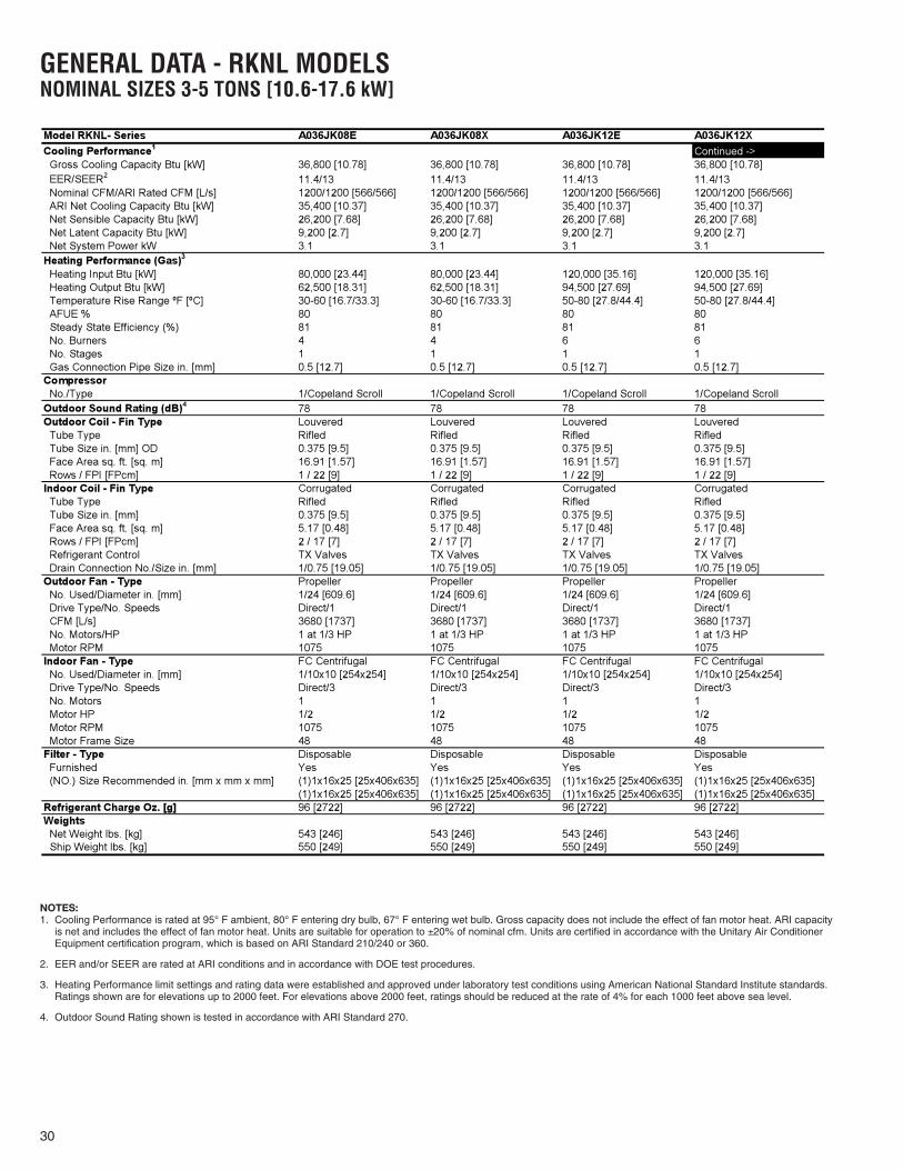
XII. GENERAL DATA - RKNL MODELSNOMINAL SIZES 3-5 TONS [10.6-17.6 kW]
Model RKNL- Series A036CK08E A036CK12E A036CL08E A036CL12ECooling Performance1 Continued -> Gross Cooling Capacity Btu [kW] 36,800 [10.78] 36,800 [10.78] 36,800 [10.78] 36,800 [10.78] EER/SEER2 11.4/13 11.4/13 11.4/13 11.4/13
1200/1200 [566/566] 1200/1200 [566/566] 1200/1200 [566/566] 1200/1200 [566/566] ARI Net Cooling Capacity Btu [kW] 35,400 [10.37] 35,400 [10.37] 35,400 [10.37] 35,400 [10.37] Net Sensible Capacity Btu [kW] 26,200 [7.68] 26,200 [7.68] 26,200 [7.68] 26,200 [7.68] Net Latent Capacity Btu [kW] 9,200 [2.7] 9,200 [2.7] 9,200 [2.7] 9,200 [2.7] Net System Power kW 3.1 3.1 3.1 3.1Heating Performance (Gas) Heating Input Btu [kW] 80,000 [23.44] 120,000 [35.16] 80,000 [23.44] 120,000 [35.16] Heating Output Btu [kW] 64,800 [18.99] 97,200 [28.48] 64,800 [18.99] 97,200 [28.48] Temperature Rise Range ºF [ºC] 30-60 [16.7/33.3] 50-80 [27.8/44.4] 30-60 [16.7/33.3] 50-80 [27.8/44.4]
80 80 80 8081 81 81 81
No. Burners 4 6 4 6 No. Stages 1 1 1 1 Gas Connection Pipe Size in. [mm] 0.5 [12.7] 0.5 [12.7] 0.5 [12.7] 0.5 [12.7]Compressor No./Type 1/Copeland Scroll 1/Copeland Scroll 1/Copeland Scroll 1/Copeland ScrollOutdoor Sound Rating (dB) 78 78 78 78Outdoor Coil - Fin Type Louvered Louvered Louvered Louvered Tube Type Rifled Rifled Rifled Rifled Tube Size in. [mm] OD 0.375 [9.5] 0.375 [9.5] 0.375 [9.5] 0.375 [9.5] Face Area sq. ft. [sq. m] 16.91 [1.57] 16.91 [1.57] 16.91 [1.57] 16.91 [1.57] Rows / FPI [FPcm] 1 / 22 [9] 1 / 22 [9] 1 / 22 [9] 1 / 22 [9]Indoor Coil - Fin Type Corrugated Corrugated Corrugated Corrugated Tube Type Rifled Rifled Rifled Rifled Tube Size in. [mm] 0.375 [9.5] 0.375 [9.5] 0.375 [9.5] 0.375 [9.5] Face Area sq. ft. [sq. m] 5.17 [0.48] 5.17 [0.48] 5.17 [0.48] 5.17 [0.48] Rows / FPI [FPcm] 2 / 17 [7] 2 / 17 [7] 2 / 17 [7] 2 / 17 [7] Refrigerant Control TX Valves TX Valves TX Valves TX Valves Drain Connection No./Size in. [mm] 1/0.75 [19.05] 1/0.75 [19.05] 1/0.75 [19.05] 1/0.75 [19.05]Outdoor Fan - Type Propeller Propeller Propeller Propeller No. Used/Diameter in. [mm] 1/24 [609.6] 1/24 [609.6] 1/24 [609.6] 1/24 [609.6] Drive Type/No. Speeds Direct/1 Direct/1 Direct/1 Direct/1 CFM [L/s] 3680 [1737] 3680 [1737] 3680 [1737] 3680 [1737] No. Motors/HP 1 at 1/3 HP 1 at 1/3 HP 1 at 1/3 HP 1 at 1/3 HP Motor RPM 1075 1075 1075 1075Indoor Fan - Type FC Centrifugal FC Centrifugal FC Centrifugal FC Centrifugal No. Used/Diameter in. [mm] 1/10x10 [254x254] 1/10x10 [254x254] 1/10x10 [254x254] 1/10x10 [254x254] Drive Type/No. Speeds Direct/3 Direct/3 Belt/Variable Belt/Variable No. Motors 1 1 1 1 Motor HP 1/2 1/2 1/2 1/2 Motor RPM 1075 1075 1725 1725 Motor Frame Size 48 48 48 48Filter - Type Disposable Disposable Disposable Disposable Furnished Yes Yes Yes Yes (NO.) Size Recommended in. [mm x mm x mm] (1)1x16x25 [25x406x635] (1)1x16x25 [25x406x635] (1)1x16x25 [25x406x635] (1)1x16x25 [25x406x635]
(1)1x16x25 [25x406x635] (1)1x16x25 [25x406x635] (1)1x16x25 [25x406x635] (1)1x16x25 [25x406x635]Refrigerant Charge Oz. [g] 96 [2722] 96 [2722] 96 [2722] 96 [2722]Weights Net Weight lbs. [kg] 543 [246] 543 [246] 543 [246] 543 [246] Ship Weight lbs. [kg] 550 [249] 550 [249] 550 [249] 550 [249]
3
4
Steady State Efficiency (%)
Nominal CFM/ARI Rated CFM [L/s]
AFUE %
NOTES:1. Cooling Performance is rated at 95° F ambient, 80° F entering dry bulb, 67° F entering wet bulb. Gross capacity does not include the effect of fan motor heat. ARI capacity
is net and includes the effect of fan motor heat. Units are suitable for operation to ±20% of nominal cfm. Units are certified in accordance with the Unitary Air ConditionerEquipment certification program, which is based on ARI Standard 210/240 or 360.
2. EER and/or SEER are rated at ARI conditions and in accordance with DOE test procedures.
3. Heating Performance limit settings and rating data were established and approved under laboratory test conditions using American National Standard Institute standards.Ratings shown are for elevations up to 2000 feet. For elevations above 2000 feet, ratings should be reduced at the rate of 4% for each 1000 feet above sea level.
4. Outdoor Sound Rating shown is tested in accordance with ARI Standard 270.

28
GENERAL DATA - RKNL MODELSNOMINAL SIZES 3-5 TONS [10.6-17.6 kW]
Model RKNL- Series A036CM08E A036CM12E A036DK08E A036DK12ECooling Performance1 Continued -> Gross Cooling Capacity Btu [kW] 36,800 [10.78] 36,800 [10.78] 36,800 [10.78] 36,800 [10.78] EER/SEER2 11.4/13 11.4/13 11.4/13 11.4/13 Nominal CFM/ARI Rated CFM [L/s] 1200/1200 [566/566] 1200/1200 [566/566] 1200/1200 [566/566] 1200/1200 [566/566] ARI Net Cooling Capacity Btu [kW] 35,400 [10.37] 35,400 [10.37] 35,400 [10.37] 35,400 [10.37] Net Sensible Capacity Btu [kW] 26,200 [7.68] 26,200 [7.68] 26,200 [7.68] 26,200 [7.68] Net Latent Capacity Btu [kW] 9,200 [2.7] 9,200 [2.7] 9,200 [2.7] 9,200 [2.7] Net System Power kW 3.1 3.1 3.1 3.1Heating Performance (Gas) Heating Input Btu [kW] 80,000 [23.44] 120,000 [35.16] 80,000 [23.44] 120,000 [35.16] Heating Output Btu [kW] 64,800 [18.99] 97,200 [28.48] 64,800 [18.99] 97,200 [28.48] Temperature Rise Range ºF [ºC] 30-60 [16.7/33.3] 50-80 [27.8/44.4] 30-60 [16.7/33.3] 50-80 [27.8/44.4]
80 80 80 80 Steady State Efficiency (%) 81 81 81 81 No. Burners 4 6 4 6 No. Stages 1 1 1 1 Gas Connection Pipe Size in. [mm] 0.5 [12.7] 0.5 [12.7] 0.5 [12.7] 0.5 [12.7]Compressor No./Type 1/Copeland Scroll 1/Copeland Scroll 1/Copeland Scroll 1/Copeland ScrollOutdoor Sound Rating (dB) 78 78 78 78Outdoor Coil - Fin Type Louvered Louvered Louvered Louvered Tube Type Rifled Rifled Rifled Rifled Tube Size in. [mm] OD 0.375 [9.5] 0.375 [9.5] 0.375 [9.5] 0.375 [9.5] Face Area sq. ft. [sq. m] 16.91 [1.57] 16.91 [1.57] 16.91 [1.57] 16.91 [1.57] Rows / FPI [FPcm] 1 / 22 [9] 1 / 22 [9] 1 / 22 [9] 1 / 22 [9]Indoor Coil - Fin Type Corrugated Corrugated Corrugated Corrugated Tube Type Rifled Rifled Rifled Rifled Tube Size in. [mm] 0.375 [9.5] 0.375 [9.5] 0.375 [9.5] 0.375 [9.5] Face Area sq. ft. [sq. m] 5.17 [0.48] 5.17 [0.48] 5.17 [0.48] 5.17 [0.48] Rows / FPI [FPcm] 2 / 17 [7] 2 / 17 [7] 2 / 17 [7] 2 / 17 [7] Refrigerant Control TX Valves TX Valves TX Valves TX Valves Drain Connection No./Size in. [mm] 1/0.75 [19.05] 1/0.75 [19.05] 1/0.75 [19.05] 1/0.75 [19.05]Outdoor Fan - Type Propeller Propeller Propeller Propeller No. Used/Diameter in. [mm] 1/24 [609.6] 1/24 [609.6] 1/24 [609.6] 1/24 [609.6] Drive Type/No. Speeds Direct/1 Direct/1 Direct/1 Direct/1 CFM [L/s] 3680 [1737] 3680 [1737] 3680 [1737] 3680 [1737] No. Motors/HP 1 at 1/3 HP 1 at 1/3 HP 1 at 1/3 HP 1 at 1/3 HP Motor RPM 1075 1075 1075 1075Indoor Fan - Type FC Centrifugal FC Centrifugal FC Centrifugal FC Centrifugal No. Used/Diameter in. [mm] 1/10x10 [254x254] 1/10x10 [254x254] 1/10x10 [254x254] 1/10x10 [254x254] Drive Type/No. Speeds Belt/Variable Belt/Variable Direct/3 Direct/3 No. Motors 1 1 1 1 Motor HP 1/2 1/2 1/2 1/2 Motor RPM 1725 1725 1075 1075 Motor Frame Size 48 48 48 48Filter - Type Disposable Disposable Disposable Disposable Furnished Yes Yes Yes Yes (NO.) Size Recommended in. [mm x mm x mm] (1)1x16x25 [25x406x635] (1)1x16x25 [25x406x635] (1)1x16x25 [25x406x635] (1)1x16x25 [25x406x635]
(1)1x16x25 [25x406x635] (1)1x16x25 [25x406x635] (1)1x16x25 [25x406x635] (1)1x16x25 [25x406x635]Refrigerant Charge Oz. [g] 96 [2722] 96 [2722] 96 [2722] 96 [2722]Weights Net Weight lbs. [kg] 543 [246] 543 [246] 543 [246] 543 [246] Ship Weight lbs. [kg] 550 [249] 550 [249] 550 [249] 550 [249]
3
4
AFUE %
NOTES:1. Cooling Performance is rated at 95° F ambient, 80° F entering dry bulb, 67° F entering wet bulb. Gross capacity does not include the effect of fan motor heat. ARI capacity
is net and includes the effect of fan motor heat. Units are suitable for operation to ±20% of nominal cfm. Units are certified in accordance with the Unitary Air ConditionerEquipment certification program, which is based on ARI Standard 210/240 or 360.
2. EER and/or SEER are rated at ARI conditions and in accordance with DOE test procedures.
3. Heating Performance limit settings and rating data were established and approved under laboratory test conditions using American National Standard Institute standards.Ratings shown are for elevations up to 2000 feet. For elevations above 2000 feet, ratings should be reduced at the rate of 4% for each 1000 feet above sea level.
4. Outdoor Sound Rating shown is tested in accordance with ARI Standard 270.

29
GENERAL DATA - RKNL MODELSNOMINAL SIZES 3-5 TONS [10.6-17.6 kW]
Model RKNL- Series A036DL08E A036DL12E A036DM08E A036DM12ECooling Performance1 Continued -> Gross Cooling Capacity Btu [kW] 36,800 [10.78] 36,800 [10.78] 36,800 [10.78] 36,800 [10.78] EER/SEER2 11.4/13 11.4/13 11.4/13 11.4/13 Nominal CFM/ARI Rated CFM [L/s] 1200/1200 [566/566] 1200/1200 [566/566] 1200/1200 [566/566] 1200/1200 [566/566] ARI Net Cooling Capacity Btu [kW] 35,400 [10.37] 35,400 [10.37] 35,400 [10.37] 35,400 [10.37] Net Sensible Capacity Btu [kW] 26,200 [7.68] 26,200 [7.68] 26,200 [7.68] 26,200 [7.68] Net Latent Capacity Btu [kW] 9,200 [2.7] 9,200 [2.7] 9,200 [2.7] 9,200 [2.7] Net System Power kW 3.1 3.1 3.1 3.1Heating Performance (Gas) Heating Input Btu [kW] 80,000 [23.44] 120,000 [35.16] 80,000 [23.44] 120,000 [35.16] Heating Output Btu [kW] 64,800 [18.99] 97,200 [28.48] 64,800 [18.99] 97,200 [28.48] Temperature Rise Range ºF [ºC] 30-60 [16.7/33.3] 50-80 [27.8/44.4] 30-60 [16.7/33.3] 50-80 [27.8/44.4]
80 80 80 80 Steady State Efficiency (%) 81 81 81 81 No. Burners 4 6 4 6 No. Stages 1 1 1 1 Gas Connection Pipe Size in. [mm] 0.5 [12.7] 0.5 [12.7] 0.5 [12.7] 0.5 [12.7]Compressor No./Type 1/Copeland Scroll 1/Copeland Scroll 1/Copeland Scroll 1/Copeland ScrollOutdoor Sound Rating (dB) 78 78 78 78Outdoor Coil - Fin Type Louvered Louvered Louvered Louvered Tube Type Rifled Rifled Rifled Rifled Tube Size in. [mm] OD 0.375 [9.5] 0.375 [9.5] 0.375 [9.5] 0.375 [9.5] Face Area sq. ft. [sq. m] 16.91 [1.57] 16.91 [1.57] 16.91 [1.57] 16.91 [1.57] Rows / FPI [FPcm] 1 / 22 [9] 1 / 22 [9] 1 / 22 [9] 1 / 22 [9]Indoor Coil - Fin Type Corrugated Corrugated Corrugated Corrugated Tube Type Rifled Rifled Rifled Rifled Tube Size in. [mm] 0.375 [9.5] 0.375 [9.5] 0.375 [9.5] 0.375 [9.5] Face Area sq. ft. [sq. m] 5.17 [0.48] 5.17 [0.48] 5.17 [0.48] 5.17 [0.48] Rows / FPI [FPcm] 2 / 17 [7] 2 / 17 [7] 2 / 17 [7] 2 / 17 [7] Refrigerant Control TX Valves TX Valves TX Valves TX Valves Drain Connection No./Size in. [mm] 1/0.75 [19.05] 1/0.75 [19.05] 1/0.75 [19.05] 1/0.75 [19.05]Outdoor Fan - Type Propeller Propeller Propeller Propeller No. Used/Diameter in. [mm] 1/24 [609.6] 1/24 [609.6] 1/24 [609.6] 1/24 [609.6] Drive Type/No. Speeds Direct/1 Direct/1 Direct/1 Direct/1 CFM [L/s] 3680 [1737] 3680 [1737] 3680 [1737] 3680 [1737] No. Motors/HP 1 at 1/3 HP 1 at 1/3 HP 1 at 1/3 HP 1 at 1/3 HP Motor RPM 1075 1075 1075 1075Indoor Fan - Type FC Centrifugal FC Centrifugal FC Centrifugal FC Centrifugal No. Used/Diameter in. [mm] 1/10x10 [254x254] 1/10x10 [254x254] 1/10x10 [254x254] 1/10x10 [254x254] Drive Type/No. Speeds Belt/Variable Belt/Variable Belt/Variable Belt/Variable No. Motors 1 1 1 1 Motor HP 1/2 1/2 1/2 1/2 Motor RPM 1725 1725 1725 1725 Motor Frame Size 48 48 48 48Filter - Type Disposable Disposable Disposable Disposable Furnished Yes Yes Yes Yes (NO.) Size Recommended in. [mm x mm x mm] (1)1x16x25 [25x406x635] (1)1x16x25 [25x406x635] (1)1x16x25 [25x406x635] (1)1x16x25 [25x406x635]
(1)1x16x25 [25x406x635] (1)1x16x25 [25x406x635] (1)1x16x25 [25x406x635] (1)1x16x25 [25x406x635]Refrigerant Charge Oz. [g] 96 [2722] 96 [2722] 96 [2722] 96 [2722]Weights Net Weight lbs. [kg] 543 [246] 543 [246] 543 [246] 543 [246] Ship Weight lbs. [kg] 550 [249] 550 [249] 550 [249] 550 [249]
3
4
AFUE %
NOTES:1. Cooling Performance is rated at 95° F ambient, 80° F entering dry bulb, 67° F entering wet bulb. Gross capacity does not include the effect of fan motor heat. ARI capacity
is net and includes the effect of fan motor heat. Units are suitable for operation to ±20% of nominal cfm. Units are certified in accordance with the Unitary Air ConditionerEquipment certification program, which is based on ARI Standard 210/240 or 360.
2. EER and/or SEER are rated at ARI conditions and in accordance with DOE test procedures.
3. Heating Performance limit settings and rating data were established and approved under laboratory test conditions using American National Standard Institute standards.Ratings shown are for elevations up to 2000 feet. For elevations above 2000 feet, ratings should be reduced at the rate of 4% for each 1000 feet above sea level.
4. Outdoor Sound Rating shown is tested in accordance with ARI Standard 270.
30
GENERAL DATA - RKNL MODELSNOMINAL SIZES 3-5 TONS [10.6-17.6 kW]
Model RKNL- Series A036JK08E A036JK08X A036JK12E A036JK12XCooling Performance1 Continued -> Gross Cooling Capacity Btu [kW] 36,800 [10.78] 36,800 [10.78] 36,800 [10.78] 36,800 [10.78] EER/SEER2 11.4/13 11.4/13 11.4/13 11.4/13 Nominal CFM/ARI Rated CFM [L/s] 1200/1200 [566/566] 1200/1200 [566/566] 1200/1200 [566/566] 1200/1200 [566/566] ARI Net Cooling Capacity Btu [kW] 35,400 [10.37] 35,400 [10.37] 35,400 [10.37] 35,400 [10.37] Net Sensible Capacity Btu [kW] 26,200 [7.68] 26,200 [7.68] 26,200 [7.68] 26,200 [7.68] Net Latent Capacity Btu [kW] 9,200 [2.7] 9,200 [2.7] 9,200 [2.7] 9,200 [2.7] Net System Power kW 3.1 3.1 3.1 3.1Heating Performance (Gas) Heating Input Btu [kW] 80,000 [23.44] 80,000 [23.44] 120,000 [35.16] 120,000 [35.16] Heating Output Btu [kW] 62,500 [18.31] 62,500 [18.31] 94,500 [27.69] 94,500 [27.69] Temperature Rise Range ºF [ºC] 30-60 [16.7/33.3] 30-60 [16.7/33.3] 50-80 [27.8/44.4] 50-80 [27.8/44.4]
80 80 80 80 Steady State Efficiency (%) 81 81 81 81 No. Burners 4 4 6 6 No. Stages 1 1 1 1 Gas Connection Pipe Size in. [mm] 0.5 [12.7] 0.5 [12.7] 0.5 [12.7] 0.5 [12.7]Compressor No./Type 1/Copeland Scroll 1/Copeland Scroll 1/Copeland Scroll 1/Copeland ScrollOutdoor Sound Rating (dB) 78 78 78 78Outdoor Coil - Fin Type Louvered Louvered Louvered Louvered Tube Type Rifled Rifled Rifled Rifled Tube Size in. [mm] OD 0.375 [9.5] 0.375 [9.5] 0.375 [9.5] 0.375 [9.5] Face Area sq. ft. [sq. m] 16.91 [1.57] 16.91 [1.57] 16.91 [1.57] 16.91 [1.57] Rows / FPI [FPcm] 1 / 22 [9] 1 / 22 [9] 1 / 22 [9] 1 / 22 [9]Indoor Coil - Fin Type Corrugated Corrugated Corrugated Corrugated Tube Type Rifled Rifled Rifled Rifled Tube Size in. [mm] 0.375 [9.5] 0.375 [9.5] 0.375 [9.5] 0.375 [9.5] Face Area sq. ft. [sq. m] 5.17 [0.48] 5.17 [0.48] 5.17 [0.48] 5.17 [0.48] Rows / FPI [FPcm] 2 / 17 [7] 2 / 17 [7] 2 / 17 [7] 2 / 17 [7] Refrigerant Control TX Valves TX Valves TX Valves TX Valves Drain Connection No./Size in. [mm] 1/0.75 [19.05] 1/0.75 [19.05] 1/0.75 [19.05] 1/0.75 [19.05]Outdoor Fan - Type Propeller Propeller Propeller Propeller No. Used/Diameter in. [mm] 1/24 [609.6] 1/24 [609.6] 1/24 [609.6] 1/24 [609.6] Drive Type/No. Speeds Direct/1 Direct/1 Direct/1 Direct/1 CFM [L/s] 3680 [1737] 3680 [1737] 3680 [1737] 3680 [1737] No. Motors/HP 1 at 1/3 HP 1 at 1/3 HP 1 at 1/3 HP 1 at 1/3 HP Motor RPM 1075 1075 1075 1075Indoor Fan - Type FC Centrifugal FC Centrifugal FC Centrifugal FC Centrifugal No. Used/Diameter in. [mm] 1/10x10 [254x254] 1/10x10 [254x254] 1/10x10 [254x254] 1/10x10 [254x254] Drive Type/No. Speeds Direct/3 Direct/3 Direct/3 Direct/3 No. Motors 1 1 1 1 Motor HP 1/2 1/2 1/2 1/2 Motor RPM 1075 1075 1075 1075 Motor Frame Size 48 48 48 48Filter - Type Disposable Disposable Disposable Disposable Furnished Yes Yes Yes Yes (NO.) Size Recommended in. [mm x mm x mm] (1)1x16x25 [25x406x635] (1)1x16x25 [25x406x635] (1)1x16x25 [25x406x635] (1)1x16x25 [25x406x635]
(1)1x16x25 [25x406x635] (1)1x16x25 [25x406x635] (1)1x16x25 [25x406x635] (1)1x16x25 [25x406x635]Refrigerant Charge Oz. [g] 96 [2722] 96 [2722] 96 [2722] 96 [2722]Weights Net Weight lbs. [kg] 543 [246] 543 [246] 543 [246] 543 [246] Ship Weight lbs. [kg] 550 [249] 550 [249] 550 [249] 550 [249]
3
4
AFUE %
NOTES:1. Cooling Performance is rated at 95° F ambient, 80° F entering dry bulb, 67° F entering wet bulb. Gross capacity does not include the effect of fan motor heat. ARI capacity
is net and includes the effect of fan motor heat. Units are suitable for operation to ±20% of nominal cfm. Units are certified in accordance with the Unitary Air ConditionerEquipment certification program, which is based on ARI Standard 210/240 or 360.
2. EER and/or SEER are rated at ARI conditions and in accordance with DOE test procedures.
3. Heating Performance limit settings and rating data were established and approved under laboratory test conditions using American National Standard Institute standards.Ratings shown are for elevations up to 2000 feet. For elevations above 2000 feet, ratings should be reduced at the rate of 4% for each 1000 feet above sea level.
4. Outdoor Sound Rating shown is tested in accordance with ARI Standard 270.

31
GENERAL DATA - RKNL MODELSNOMINAL SIZES 3-5 TONS [10.6-17.6 kW]
Model RKNL- Series A042CK08E A042CK12E A042CL08E A042CL12ECooling Performance1 Continued -> Gross Cooling Capacity Btu [kW] 42,500 [12.45] 42,500 [12.45] 42,500 [12.45] 42,500 [12.45] EER/SEER2 11.2/13 11.2/13 11.2/13 11.2/13 Nominal CFM/ARI Rated CFM [L/s] 1400/1450 [661/684] 1400/1450 [661/684] 1400/1450 [661/684] 1400/1450 [661/684] ARI Net Cooling Capacity Btu [kW] 40,500 [11.87] 40,500 [11.87] 40,500 [11.87] 40,500 [11.87] Net Sensible Capacity Btu [kW] 30,600 [8.97] 30,600 [8.97] 30,600 [8.97] 30,600 [8.97] Net Latent Capacity Btu [kW] 9,900 [2.9] 9,900 [2.9] 9,900 [2.9] 9,900 [2.9] Net System Power kW 3.62 3.62 3.62 3.62Heating Performance (Gas) Heating Input Btu [kW] 80,000 [23.44] 120,000 [35.16] 80,000 [23.44] 120,000 [35.16] Heating Output Btu [kW] 64,800 [18.99] 97,200 [28.48] 64,800 [18.99] 97,200 [28.48] Temperature Rise Range ºF [ºC] 30-60 [16.7/33.3] 50-80 [27.8/44.4] 30-60 [16.7/33.3] 50-80 [27.8/44.4]
80 80 80 80 Steady State Efficiency (%) 81 81 81 81 No. Burners 4 6 4 6 No. Stages 1 1 1 1 Gas Connection Pipe Size in. [mm] 0.5 [12.7] 0.5 [12.7] 0.5 [12.7] 0.5 [12.7]Compressor No./Type 1/Copeland Scroll 1/Copeland Scroll 1/Copeland Scroll 1/Copeland ScrollOutdoor Sound Rating (dB) 78 78 78 78Outdoor Coil - Fin Type Louvered Louvered Louvered Louvered Tube Type Rifled Rifled Rifled Rifled Tube Size in. [mm] OD 0.375 [9.5] 0.375 [9.5] 0.375 [9.5] 0.375 [9.5] Face Area sq. ft. [sq. m] 16.91 [1.57] 16.91 [1.57] 16.91 [1.57] 16.91 [1.57] Rows / FPI [FPcm] 1.53 / 22 [9] 1.53 / 22 [9] 1.53 / 22 [9] 1.53 / 22 [9]Indoor Coil - Fin Type Corrugated Corrugated Corrugated Corrugated Tube Type Rifled Rifled Rifled Rifled Tube Size in. [mm] 0.375 [9.5] 0.375 [9.5] 0.375 [9.5] 0.375 [9.5] Face Area sq. ft. [sq. m] 5.17 [0.48] 5.17 [0.48] 5.17 [0.48] 5.17 [0.48] Rows / FPI [FPcm] 3 / 13 [5] 3 / 13 [5] 3 / 13 [5] 3 / 13 [5] Refrigerant Control TX Valves TX Valves TX Valves TX Valves Drain Connection No./Size in. [mm] 1/0.75 [19.05] 1/0.75 [19.05] 1/0.75 [19.05] 1/0.75 [19.05]Outdoor Fan - Type Propeller Propeller Propeller Propeller No. Used/Diameter in. [mm] 1/24 [609.6] 1/24 [609.6] 1/24 [609.6] 1/24 [609.6] Drive Type/No. Speeds Direct/1 Direct/1 Direct/1 Direct/1 CFM [L/s] 3680 [1737] 3680 [1737] 3680 [1737] 3680 [1737] No. Motors/HP 1 at 1/3 HP 1 at 1/3 HP 1 at 1/3 HP 1 at 1/3 HP Motor RPM 1075 1075 1075 1075Indoor Fan - Type FC Centrifugal FC Centrifugal FC Centrifugal FC Centrifugal No. Used/Diameter in. [mm] 1/10x10 [254x254] 1/10x10 [254x254] 1/10x10 [254x254] 1/10x10 [254x254] Drive Type/No. Speeds Direct/3 Direct/3 Belt/Variable Belt/Variable No. Motors 1 1 1 1 Motor HP 1/2 1/2 1/2 1/2 Motor RPM 1075 1075 1725 1725 Motor Frame Size 48 48 48 48Filter - Type Disposable Disposable Disposable Disposable Furnished Yes Yes Yes Yes (NO.) Size Recommended in. [mm x mm x mm] (1)1x16x25 [25x406x635] (1)1x16x25 [25x406x635] (1)1x16x25 [25x406x635] (1)1x16x25 [25x406x635]
(1)1x16x25 [25x406x635] (1)1x16x25 [25x406x635] (1)1x16x25 [25x406x635] (1)1x16x25 [25x406x635]Refrigerant Charge Oz. [g] 125 [3544] 125 [3544] 125 [3544] 125 [3544]Weights Net Weight lbs. [kg] 570 [259] 579 [263] 570 [259] 579 [263] Ship Weight lbs. [kg] 577 [262] 586 [266] 577 [262] 586 [266]
3
4
AFUE %
NOTES:1. Cooling Performance is rated at 95° F ambient, 80° F entering dry bulb, 67° F entering wet bulb. Gross capacity does not include the effect of fan motor heat. ARI capacity
is net and includes the effect of fan motor heat. Units are suitable for operation to ±20% of nominal cfm. Units are certified in accordance with the Unitary Air ConditionerEquipment certification program, which is based on ARI Standard 210/240 or 360.
2. EER and/or SEER are rated at ARI conditions and in accordance with DOE test procedures.
3. Heating Performance limit settings and rating data were established and approved under laboratory test conditions using American National Standard Institute standards.Ratings shown are for elevations up to 2000 feet. For elevations above 2000 feet, ratings should be reduced at the rate of 4% for each 1000 feet above sea level.
4. Outdoor Sound Rating shown is tested in accordance with ARI Standard 270.

32
GENERAL DATA - RKNL MODELSNOMINAL SIZES 3-5 TONS [10.6-17.6 kW]
Model RKNL- Series A042CM08E A042CM12E A042DK08E A042DK12ECooling Performance1 Continued -> Gross Cooling Capacity Btu [kW] 42,500 [12.45] 42,500 [12.45] 42,500 [12.45] 42,500 [12.45] EER/SEER2 11.2/13 11.2/13 11.2/13 11.2/13 Nominal CFM/ARI Rated CFM [L/s] 1400/1450 [661/684] 1400/1450 [661/684] 1400/1450 [661/684] 1400/1450 [661/684] ARI Net Cooling Capacity Btu [kW] 40,500 [11.87] 40,500 [11.87] 40,500 [11.87] 40,500 [11.87] Net Sensible Capacity Btu [kW] 30,600 [8.97] 30,600 [8.97] 30,600 [8.97] 30,600 [8.97] Net Latent Capacity Btu [kW] 9,900 [2.9] 9,900 [2.9] 9,900 [2.9] 9,900 [2.9] Net System Power kW 3.62 3.62 3.62 3.62Heating Performance (Gas) Heating Input Btu [kW] 80,000 [23.44] 120,000 [35.16] 80,000 [23.44] 120,000 [35.16] Heating Output Btu [kW] 64,800 [18.99] 97,200 [28.48] 64,800 [18.99] 97,200 [28.48] Temperature Rise Range ºF [ºC] 30-60 [16.7/33.3] 50-80 [27.8/44.4] 30-60 [16.7/33.3] 50-80 [27.8/44.4]
80 80 80 80 Steady State Efficiency (%) 81 81 81 81 No. Burners 4 6 4 6 No. Stages 1 1 1 1 Gas Connection Pipe Size in. [mm] 0.5 [12.7] 0.5 [12.7] 0.5 [12.7] 0.5 [12.7]Compressor No./Type 1/Copeland Scroll 1/Copeland Scroll 1/Copeland Scroll 1/Copeland ScrollOutdoor Sound Rating (dB) 78 78 78 78Outdoor Coil - Fin Type Louvered Louvered Louvered Louvered Tube Type Rifled Rifled Rifled Rifled Tube Size in. [mm] OD 0.375 [9.5] 0.375 [9.5] 0.375 [9.5] 0.375 [9.5] Face Area sq. ft. [sq. m] 16.91 [1.57] 16.91 [1.57] 16.91 [1.57] 16.91 [1.57] Rows / FPI [FPcm] 1.53 / 22 [9] 1.53 / 22 [9] 1.53 / 22 [9] 1.53 / 22 [9]Indoor Coil - Fin Type Corrugated Corrugated Corrugated Corrugated Tube Type Rifled Rifled Rifled Rifled Tube Size in. [mm] 0.375 [9.5] 0.375 [9.5] 0.375 [9.5] 0.375 [9.5] Face Area sq. ft. [sq. m] 5.17 [0.48] 5.17 [0.48] 5.17 [0.48] 5.17 [0.48] Rows / FPI [FPcm] 3 / 13 [5] 3 / 13 [5] 3 / 13 [5] 3 / 13 [5] Refrigerant Control TX Valves TX Valves TX Valves TX Valves Drain Connection No./Size in. [mm] 1/0.75 [19.05] 1/0.75 [19.05] 1/0.75 [19.05] 1/0.75 [19.05]Outdoor Fan - Type Propeller Propeller Propeller Propeller No. Used/Diameter in. [mm] 1/24 [609.6] 1/24 [609.6] 1/24 [609.6] 1/24 [609.6] Drive Type/No. Speeds Direct/1 Direct/1 Direct/1 Direct/1 CFM [L/s] 3680 [1737] 3680 [1737] 3680 [1737] 3680 [1737] No. Motors/HP 1 at 1/3 HP 1 at 1/3 HP 1 at 1/3 HP 1 at 1/3 HP Motor RPM 1075 1075 1075 1075Indoor Fan - Type FC Centrifugal FC Centrifugal FC Centrifugal FC Centrifugal No. Used/Diameter in. [mm] 1/10x10 [254x254] 1/10x10 [254x254] 1/10x10 [254x254] 1/10x10 [254x254] Drive Type/No. Speeds Belt/Variable Belt/Variable Direct/3 Direct/3 No. Motors 1 1 1 1 Motor HP 1/2 1/2 1/2 1/2 Motor RPM 1725 1725 1075 1075 Motor Frame Size 48 48 48 48Filter - Type Disposable Disposable Disposable Disposable Furnished Yes Yes Yes Yes (NO.) Size Recommended in. [mm x mm x mm] (1)1x16x25 [25x406x635] (1)1x16x25 [25x406x635] (1)1x16x25 [25x406x635] (1)1x16x25 [25x406x635]
(1)1x16x25 [25x406x635] (1)1x16x25 [25x406x635] (1)1x16x25 [25x406x635] (1)1x16x25 [25x406x635]Refrigerant Charge Oz. [g] 125 [3544] 125 [3544] 125 [3544] 125 [3544]Weights Net Weight lbs. [kg] 570 [259] 570 [259] 570 [259] 579 [263] Ship Weight lbs. [kg] 577 [262] 577 [262] 577 [262] 586 [266]
3
4
AFUE %
NOTES:1. Cooling Performance is rated at 95° F ambient, 80° F entering dry bulb, 67° F entering wet bulb. Gross capacity does not include the effect of fan motor heat. ARI capacity
is net and includes the effect of fan motor heat. Units are suitable for operation to ±20% of nominal cfm. Units are certified in accordance with the Unitary Air ConditionerEquipment certification program, which is based on ARI Standard 210/240 or 360.
2. EER and/or SEER are rated at ARI conditions and in accordance with DOE test procedures.
3. Heating Performance limit settings and rating data were established and approved under laboratory test conditions using American National Standard Institute standards.Ratings shown are for elevations up to 2000 feet. For elevations above 2000 feet, ratings should be reduced at the rate of 4% for each 1000 feet above sea level.
4. Outdoor Sound Rating shown is tested in accordance with ARI Standard 270.

33
GENERAL DATA - RKNL MODELSNOMINAL SIZES 3-5 TONS [10.6-17.6 kW]
Model RKNL- Series A042DL08E A042DL12E A042DM08E A042DM12ECooling Performance1 Continued -> Gross Cooling Capacity Btu [kW] 42,500 [12.45] 42,500 [12.45] 42,500 [12.45] 42,500 [12.45] EER/SEER2 11.2/13 11.2/13 11.2/13 11.2/13 Nominal CFM/ARI Rated CFM [L/s] 1400/1450 [661/684] 1400/1450 [661/684] 1400/1450 [661/684] 1400/1450 [661/684] ARI Net Cooling Capacity Btu [kW] 40,500 [11.87] 40,500 [11.87] 40,500 [11.87] 40,500 [11.87] Net Sensible Capacity Btu [kW] 30,600 [8.97] 30,600 [8.97] 30,600 [8.97] 30,600 [8.97] Net Latent Capacity Btu [kW] 9,900 [2.9] 9,900 [2.9] 9,900 [2.9] 9,900 [2.9] Net System Power kW 3.62 3.62 3.62 3.62Heating Performance (Gas) Heating Input Btu [kW] 80,000 [23.44] 120,000 [35.16] 80,000 [23.44] 120,000 [35.16] Heating Output Btu [kW] 64,800 [18.99] 97,200 [28.48] 64,800 [18.99] 97,200 [28.48] Temperature Rise Range ºF [ºC] 30-60 [16.7/33.3] 50-80 [27.8/44.4] 30-60 [16.7/33.3] 50-80 [27.8/44.4]
80 80 80 80 Steady State Efficiency (%) 81 81 81 81 No. Burners 4 6 4 6 No. Stages 1 1 1 1 Gas Connection Pipe Size in. [mm] 0.5 [12.7] 0.5 [12.7] 0.5 [12.7] 0.5 [12.7]Compressor No./Type 1/Copeland Scroll 1/Copeland Scroll 1/Copeland Scroll 1/Copeland ScrollOutdoor Sound Rating (dB) 78 78 78 78Outdoor Coil - Fin Type Louvered Louvered Louvered Louvered Tube Type Rifled Rifled Rifled Rifled Tube Size in. [mm] OD 0.375 [9.5] 0.375 [9.5] 0.375 [9.5] 0.375 [9.5] Face Area sq. ft. [sq. m] 16.91 [1.57] 16.91 [1.57] 16.91 [1.57] 16.91 [1.57] Rows / FPI [FPcm] 1.53 / 22 [9] 1.53 / 22 [9] 1.53 / 22 [9] 1.53 / 22 [9]Indoor Coil - Fin Type Corrugated Corrugated Corrugated Corrugated Tube Type Rifled Rifled Rifled Rifled Tube Size in. [mm] 0.375 [9.5] 0.375 [9.5] 0.375 [9.5] 0.375 [9.5] Face Area sq. ft. [sq. m] 5.17 [0.48] 5.17 [0.48] 5.17 [0.48] 5.17 [0.48] Rows / FPI [FPcm] 3 / 13 [5] 3 / 13 [5] 3 / 13 [5] 3 / 13 [5] Refrigerant Control TX Valves TX Valves TX Valves TX Valves Drain Connection No./Size in. [mm] 1/0.75 [19.05] 1/0.75 [19.05] 1/0.75 [19.05] 1/0.75 [19.05]Outdoor Fan - Type Propeller Propeller Propeller Propeller No. Used/Diameter in. [mm] 1/24 [609.6] 1/24 [609.6] 1/24 [609.6] 1/24 [609.6] Drive Type/No. Speeds Direct/1 Direct/1 Direct/1 Direct/1 CFM [L/s] 3680 [1737] 3680 [1737] 3680 [1737] 3680 [1737] No. Motors/HP 1 at 1/3 HP 1 at 1/3 HP 1 at 1/3 HP 1 at 1/3 HP Motor RPM 1075 1075 1075 1075Indoor Fan - Type FC Centrifugal FC Centrifugal FC Centrifugal FC Centrifugal No. Used/Diameter in. [mm] 1/10x10 [254x254] 1/10x10 [254x254] 1/10x10 [254x254] 1/10x10 [254x254] Drive Type/No. Speeds Belt/Variable Belt/Variable Belt/Variable Belt/Variable No. Motors 1 1 1 1 Motor HP 1/2 1/2 1/2 1/2 Motor RPM 1725 1725 1725 1725 Motor Frame Size 48 48 48 48Filter - Type Disposable Disposable Disposable Disposable Furnished Yes Yes Yes Yes (NO.) Size Recommended in. [mm x mm x mm] (1)1x16x25 [25x406x635] (1)1x16x25 [25x406x635] (1)1x16x25 [25x406x635] (1)1x16x25 [25x406x635]
(1)1x16x25 [25x406x635] (1)1x16x25 [25x406x635] (1)1x16x25 [25x406x635] (1)1x16x25 [25x406x635]Refrigerant Charge Oz. [g] 125 [3544] 125 [3544] 125 [3544] 125 [3544]Weights Net Weight lbs. [kg] 570 [259] 570 [259] 570 [259] 570 [259] Ship Weight lbs. [kg] 577 [262] 577 [262] 577 [262] 577 [262]
3
4
AFUE %
NOTES:1. Cooling Performance is rated at 95° F ambient, 80° F entering dry bulb, 67° F entering wet bulb. Gross capacity does not include the effect of fan motor heat. ARI capacity
is net and includes the effect of fan motor heat. Units are suitable for operation to ±20% of nominal cfm. Units are certified in accordance with the Unitary Air ConditionerEquipment certification program, which is based on ARI Standard 210/240 or 360.
2. EER and/or SEER are rated at ARI conditions and in accordance with DOE test procedures.
3. Heating Performance limit settings and rating data were established and approved under laboratory test conditions using American National Standard Institute standards.Ratings shown are for elevations up to 2000 feet. For elevations above 2000 feet, ratings should be reduced at the rate of 4% for each 1000 feet above sea level.
4. Outdoor Sound Rating shown is tested in accordance with ARI Standard 270.

34
GENERAL DATA - RKNL MODELSNOMINAL SIZES 3-5 TONS [10.6-17.6 kW]
Model RKNL- Series A042JK08E A042JK08X A042JK12E A042JK12XCooling Performance1 Continued -> Gross Cooling Capacity Btu [kW] 42,500 [12.45] 42,500 [12.45] 42,500 [12.45] 42,500 [12.45] EER/SEER2 11.2/13 11.2/13 11.2/13 11.2/13 Nominal CFM/ARI Rated CFM [L/s] 1400/1450 [661/684] 1400/1450 [661/684] 1400/1450 [661/684] 1400/1450 [661/684] ARI Net Cooling Capacity Btu [kW] 40,500 [11.87] 40,500 [11.87] 40,500 [11.87] 40,500 [11.87] Net Sensible Capacity Btu [kW] 30,600 [8.97] 30,600 [8.97] 30,600 [8.97] 30,600 [8.97] Net Latent Capacity Btu [kW] 9,900 [2.9] 9,900 [2.9] 9,900 [2.9] 9,900 [2.9] Net System Power kW 3.62 3.62 3.62 3.62Heating Performance (Gas) Heating Input Btu [kW] 80,000 [23.44] 80,000 [23.44] 120,000 [35.16] 120,000 [35.16] Heating Output Btu [kW] 62,500 [18.31] 62,500 [18.31] 94,500 [27.69] 94,500 [27.69] Temperature Rise Range ºF [ºC] 30-60 [16.7/33.3] 30-60 [16.7/33.3] 50-80 [27.8/44.4] 50-80 [27.8/44.4]
80 80 80 80 Steady State Efficiency (%) 81 81 81 81 No. Burners 4 4 6 6 No. Stages 1 1 1 1 Gas Connection Pipe Size in. [mm] 0.5 [12.7] 0.5 [12.7] 0.5 [12.7] 0.5 [12.7]Compressor No./Type 1/Copeland Scroll 1/Copeland Scroll 1/Copeland Scroll 1/Copeland ScrollOutdoor Sound Rating (dB) 78 78 78 78Outdoor Coil - Fin Type Louvered Louvered Louvered Louvered Tube Type Rifled Rifled Rifled Rifled Tube Size in. [mm] OD 0.375 [9.5] 0.375 [9.5] 0.375 [9.5] 0.375 [9.5] Face Area sq. ft. [sq. m] 16.91 [1.57] 16.91 [1.57] 16.91 [1.57] 16.91 [1.57] Rows / FPI [FPcm] 1.53 / 22 [9] 1.53 / 22 [9] 1.53 / 22 [9] 1.53 / 22 [9]Indoor Coil - Fin Type Corrugated Corrugated Corrugated Corrugated Tube Type Rifled Rifled Rifled Rifled Tube Size in. [mm] 0.375 [9.5] 0.375 [9.5] 0.375 [9.5] 0.375 [9.5] Face Area sq. ft. [sq. m] 5.17 [0.48] 5.17 [0.48] 5.17 [0.48] 5.17 [0.48] Rows / FPI [FPcm] 3 / 13 [5] 3 / 13 [5] 3 / 13 [5] 3 / 13 [5] Refrigerant Control TX Valves TX Valves TX Valves TX Valves Drain Connection No./Size in. [mm] 1/0.75 [19.05] 1/0.75 [19.05] 1/0.75 [19.05] 1/0.75 [19.05]Outdoor Fan - Type Propeller Propeller Propeller Propeller No. Used/Diameter in. [mm] 1/24 [609.6] 1/24 [609.6] 1/24 [609.6] 1/24 [609.6] Drive Type/No. Speeds Direct/1 Direct/1 Direct/1 Direct/1 CFM [L/s] 3680 [1737] 3680 [1737] 3680 [1737] 3680 [1737] No. Motors/HP 1 at 1/3 HP 1 at 1/3 HP 1 at 1/3 HP 1 at 1/3 HP Motor RPM 1075 1075 1075 1075Indoor Fan - Type FC Centrifugal FC Centrifugal FC Centrifugal FC Centrifugal No. Used/Diameter in. [mm] 1/10x10 [254x254] 1/10x10 [254x254] 1/10x10 [254x254] 1/10x10 [254x254] Drive Type/No. Speeds Direct/3 Direct/3 Direct/3 Direct/3 No. Motors 1 1 1 1 Motor HP 1/2 1/2 1/2 1/2 Motor RPM 1075 1075 1725 1075 Motor Frame Size 48 48 48 48Filter - Type Disposable Disposable Disposable Disposable Furnished Yes Yes Yes Yes (NO.) Size Recommended in. [mm x mm x mm] (1)1x16x25 [25x406x635] (1)1x16x25 [25x406x635] (1)1x16x25 [25x406x635] (1)1x16x25 [25x406x635]
(1)1x16x25 [25x406x635] (1)1x16x25 [25x406x635] (1)1x16x25 [25x406x635] (1)1x16x25 [25x406x635]Refrigerant Charge Oz. [g] 125 [3544] 125 [3544] 125 [3544] 125 [3544]Weights Net Weight lbs. [kg] 570 [259] 570 [259] 579 [263] 579 [263] Ship Weight lbs. [kg] 577 [262] 577 [262] 586 [266] 586 [266]
3
4
AFUE %
NOTES:1. Cooling Performance is rated at 95° F ambient, 80° F entering dry bulb, 67° F entering wet bulb. Gross capacity does not include the effect of fan motor heat. ARI capacity
is net and includes the effect of fan motor heat. Units are suitable for operation to ±20% of nominal cfm. Units are certified in accordance with the Unitary Air ConditionerEquipment certification program, which is based on ARI Standard 210/240 or 360.
2. EER and/or SEER are rated at ARI conditions and in accordance with DOE test procedures.
3. Heating Performance limit settings and rating data were established and approved under laboratory test conditions using American National Standard Institute standards.Ratings shown are for elevations up to 2000 feet. For elevations above 2000 feet, ratings should be reduced at the rate of 4% for each 1000 feet above sea level.
4. Outdoor Sound Rating shown is tested in accordance with ARI Standard 270.

35
GENERAL DATA - RKNL MODELSNOMINAL SIZES 3-5 TONS [10.6-17.6 kW]
Model RKNL- Series A048CK08E A048CK10E A048CK13E A048CL08ECooling Performance1 Continued -> Gross Cooling Capacity Btu [kW] 50,000 [14.65] 50,000 [14.65] 50,000 [14.65] 50,000 [14.65] EER/SEER2 11.45/13 11.45/13 11.45/13 11.45/13 Nominal CFM/ARI Rated CFM [L/s] 1600/1600 [755/755] 1600/1600 [755/755] 1600/1600 [755/755] 1600/1600 [755/755] ARI Net Cooling Capacity Btu [kW] 48,000 [14.06] 48,000 [14.06] 48,000 [14.06] 48,000 [14.06] Net Sensible Capacity Btu [kW] 35,600 [10.43] 35,600 [10.43] 35,600 [10.43] 35,600 [10.43] Net Latent Capacity Btu [kW] 12,400 [3.63] 12,400 [3.63] 12,400 [3.63] 12,400 [3.63] Net System Power kW 4.19 4.19 4.19 4.19Heating Performance (Gas) Heating Input Btu [kW] 80,000 [23.44] 100,000 [29.3] 135,000 [39.56] 80,000 [23.44] Heating Output Btu [kW] 64,800 [18.99] 81,000 [23.73] 109,400 [32.05] 64,800 [18.99] Temperature Rise Range ºF [ºC] 30-60 [16.7/33.3] 40-70 [22.2/38.9] 50-80 [27.8/44.4] 30-60 [16.7/33.3]
80 80 80 80 Steady State Efficiency (%) 81 81 81 81 No. Burners 4 5 6 4 No. Stages 1 1 1 1 Gas Connection Pipe Size in. [mm] 0.5 [12.7] 0.5 [12.7] 0.5 [12.7] 0.5 [12.7]Compressor No./Type 1/Copeland Scroll 1/Copeland Scroll 1/Copeland Scroll 1/Copeland ScrollOutdoor Sound Rating (dB) 78 78 78 78Outdoor Coil - Fin Type Louvered Louvered Louvered Louvered Tube Type Rifled Rifled Rifled Rifled Tube Size in. [mm] OD 0.375 [9.5] 0.375 [9.5] 0.375 [9.5] 0.375 [9.5] Face Area sq. ft. [sq. m] 16.56 [1.54] 16.56 [1.54] 16.56 [1.54] 16.56 [1.54] Rows / FPI [FPcm] 2 / 22 [9] 2 / 22 [9] 2 / 22 [9] 2 / 22 [9]Indoor Coil - Fin Type Corrugated Corrugated Corrugated Corrugated Tube Type Rifled Rifled Rifled Rifled Tube Size in. [mm] 0.375 [9.5] 0.375 [9.5] 0.375 [9.5] 0.375 [9.5] Face Area sq. ft. [sq. m] 5.17 [0.48] 5.17 [0.48] 5.17 [0.48] 5.17 [0.48] Rows / FPI [FPcm] 3 / 15 [6] 3 / 15 [6] 3 / 15 [6] 3 / 15 [6] Refrigerant Control TX Valves TX Valves TX Valves TX Valves Drain Connection No./Size in. [mm] 1/0.75 [19.05] 1/0.75 [19.05] 1/0.75 [19.05] 1/0.75 [19.05]Outdoor Fan - Type Propeller Propeller Propeller Propeller No. Used/Diameter in. [mm] 1/24 [609.6] 1/24 [609.6] 1/24 [609.6] 1/24 [609.6] Drive Type/No. Speeds Direct/1 Direct/1 Direct/1 Direct/1 CFM [L/s] 3680 [1737] 3680 [1737] 3680 [1737] 3680 [1737] No. Motors/HP 1 at 1/3 HP 1 at 1/3 HP 1 at 1/3 HP 1 at 1/3 HP Motor RPM 1075 1075 1075 1075Indoor Fan - Type FC Centrifugal FC Centrifugal FC Centrifugal FC Centrifugal No. Used/Diameter in. [mm] 1/10x10 [254x254] 1/10x10 [254x254] 1/10x10 [254x254] 1/10x10 [254x254] Drive Type/No. Speeds Direct/3 Direct/3 Direct/3 Belt/Variable No. Motors 1 1 1 1 Motor HP 1/2 1/2 1/2 1/2 Motor RPM 1075 1075 1075 1725 Motor Frame Size 48 48 48 48Filter - Type Disposable Disposable Disposable Disposable Furnished Yes Yes Yes Yes (NO.) Size Recommended in. [mm x mm x mm] (1)1x16x25 [25x406x635] (1)1x16x25 [25x406x635] (1)1x16x25 [25x406x635] (1)1x16x25 [25x406x635]
(1)1x16x25 [25x406x635] (1)1x16x25 [25x406x635] (1)1x16x25 [25x406x635] (1)1x16x25 [25x406x635]Refrigerant Charge Oz. [g] 165 [4678] 165 [4678] 165 [4678] 165 [4678]Weights Net Weight lbs. [kg] 580 [263] 580 [263] 585 [265] 580 [263] Ship Weight lbs. [kg] 587 [266] 587 [266] 592 [269] 587 [266]
3
4
AFUE %
NOTES:1. Cooling Performance is rated at 95° F ambient, 80° F entering dry bulb, 67° F entering wet bulb. Gross capacity does not include the effect of fan motor heat. ARI capacity
is net and includes the effect of fan motor heat. Units are suitable for operation to ±20% of nominal cfm. Units are certified in accordance with the Unitary Air ConditionerEquipment certification program, which is based on ARI Standard 210/240 or 360.
2. EER and/or SEER are rated at ARI conditions and in accordance with DOE test procedures.
3. Heating Performance limit settings and rating data were established and approved under laboratory test conditions using American National Standard Institute standards.Ratings shown are for elevations up to 2000 feet. For elevations above 2000 feet, ratings should be reduced at the rate of 4% for each 1000 feet above sea level.
4. Outdoor Sound Rating shown is tested in accordance with ARI Standard 270.

36
GENERAL DATA - RKNL MODELSNOMINAL SIZES 3-5 TONS [10.6-17.6 kW]
Model RKNL- Series A048CL10E A048CL13E A048CM08E A048CM10ECooling Performance1 Continued -> Gross Cooling Capacity Btu [kW] 50,000 [14.65] 50,000 [14.65] 50,000 [14.65] 50,000 [14.65] EER/SEER2 11.45/13 11.45/13 11.45/13 11.45/13 Nominal CFM/ARI Rated CFM [L/s] 1600/1600 [755/755] 1600/1600 [755/755] 1600/1600 [755/755] 1600/1600 [755/755] ARI Net Cooling Capacity Btu [kW] 48,000 [14.06] 48,000 [14.06] 48,000 [14.06] 48,000 [14.06] Net Sensible Capacity Btu [kW] 35,600 [10.43] 35,600 [10.43] 35,600 [10.43] 35,600 [10.43] Net Latent Capacity Btu [kW] 12,400 [3.63] 12,400 [3.63] 12,400 [3.63] 12,400 [3.63] Net System Power kW 4.19 4.19 4.19 4.19Heating Performance (Gas) Heating Input Btu [kW] 100,000 [29.3] 135,000 [39.56] 80,000 [23.44] 100,000 [29.3] Heating Output Btu [kW] 81,000 [23.73] 109,400 [32.05] 64,800 [18.99] 81,000 [23.73] Temperature Rise Range ºF [ºC] 30-60 [16.7/33.3] 50-80 [27.8/44.4] 30-60 [16.7/33.3] 30-60 [16.7/33.3]
80 80 80 80 Steady State Efficiency (%) 81 81 81 81 No. Burners 5 6 4 5 No. Stages 1 1 1 1 Gas Connection Pipe Size in. [mm] 0.5 [12.7] 0.5 [12.7] 0.5 [12.7] 0.5 [12.7]Compressor No./Type 1/Copeland Scroll 1/Copeland Scroll 1/Copeland Scroll 1/Copeland ScrollOutdoor Sound Rating (dB) 78 78 78 78Outdoor Coil - Fin Type Louvered Louvered Louvered Louvered Tube Type Rifled Rifled Rifled Rifled Tube Size in. [mm] OD 0.375 [9.5] 0.375 [9.5] 0.375 [9.5] 0.375 [9.5] Face Area sq. ft. [sq. m] 16.56 [1.54] 16.56 [1.54] 16.56 [1.54] 16.56 [1.54] Rows / FPI [FPcm] 2 / 22 [9] 2 / 22 [9] 2 / 22 [9] 2 / 22 [9]Indoor Coil - Fin Type Corrugated Corrugated Corrugated Corrugated Tube Type Rifled Rifled Rifled Rifled Tube Size in. [mm] 0.375 [9.5] 0.375 [9.5] 0.375 [9.5] 0.375 [9.5] Face Area sq. ft. [sq. m] 5.17 [0.48] 5.17 [0.48] 5.17 [0.48] 5.17 [0.48] Rows / FPI [FPcm] 3 / 15 [6] 3 / 15 [6] 3 / 15 [6] 3 / 15 [6] Refrigerant Control TX Valves TX Valves TX Valves TX Valves Drain Connection No./Size in. [mm] 1/0.75 [19.05] 1/0.75 [19.05] 1/0.75 [19.05] 1/0.75 [19.05]Outdoor Fan - Type Propeller Propeller Propeller Propeller No. Used/Diameter in. [mm] 1/24 [609.6] 1/24 [609.6] 1/24 [609.6] 1/24 [609.6] Drive Type/No. Speeds Direct/1 Direct/1 Direct/1 Direct/1 CFM [L/s] 3680 [1737] 3680 [1737] 3680 [1737] 3680 [1737] No. Motors/HP 1 at 1/3 HP 1 at 1/3 HP 1 at 1/3 HP 1 at 1/3 HP Motor RPM 1075 1075 1075 1075Indoor Fan - Type FC Centrifugal FC Centrifugal FC Centrifugal FC Centrifugal No. Used/Diameter in. [mm] 1/10x10 [254x254] 1/10x10 [254x254] 1/10x10 [254x254] 1/10x10 [254x254] Drive Type/No. Speeds Belt/Variable Belt/Variable Belt/Variable Belt/Variable No. Motors 1 1 1 1 Motor HP 1/2 1/2 3/4 3/4 Motor RPM 1725 1725 1725 1725 Motor Frame Size 48 48 56 56Filter - Type Disposable Disposable Disposable Disposable Furnished Yes Yes Yes Yes (NO.) Size Recommended in. [mm x mm x mm] (1)1x16x25 [25x406x635] (1)1x16x25 [25x406x635] (1)1x16x25 [25x406x635] (1)1x16x25 [25x406x635]
(1)1x16x25 [25x406x635] (1)1x16x25 [25x406x635] (1)1x16x25 [25x406x635] (1)1x16x25 [25x406x635]Refrigerant Charge Oz. [g] 165 [4678] 165 [4678] 165 [4678] 165 [4678]Weights Net Weight lbs. [kg] 580 [263] 585 [265] 580 [263] 580 [263] Ship Weight lbs. [kg] 587 [266] 592 [269] 587 [266] 587 [266]
3
4
AFUE %
NOTES:1. Cooling Performance is rated at 95° F ambient, 80° F entering dry bulb, 67° F entering wet bulb. Gross capacity does not include the effect of fan motor heat. ARI capacity
is net and includes the effect of fan motor heat. Units are suitable for operation to ±20% of nominal cfm. Units are certified in accordance with the Unitary Air ConditionerEquipment certification program, which is based on ARI Standard 210/240 or 360.
2. EER and/or SEER are rated at ARI conditions and in accordance with DOE test procedures.
3. Heating Performance limit settings and rating data were established and approved under laboratory test conditions using American National Standard Institute standards.Ratings shown are for elevations up to 2000 feet. For elevations above 2000 feet, ratings should be reduced at the rate of 4% for each 1000 feet above sea level.
4. Outdoor Sound Rating shown is tested in accordance with ARI Standard 270.

37
GENERAL DATA - RKNL MODELSNOMINAL SIZES 3-5 TONS [10.6-17.6 kW]
Model RKNL- Series A048CM13E A048DK08E A048DK10E A048DK13ECooling Performance1 Continued -> Gross Cooling Capacity Btu [kW] 50,000 [14.65] 50,000 [14.65] 50,000 [14.65] 50,000 [14.65] EER/SEER2 11.45/13 11.45/13 11.45/13 11.45/13 Nominal CFM/ARI Rated CFM [L/s] 1600/1600 [755/755] 1600/1600 [755/755] 1600/1600 [755/755] 1600/1600 [755/755] ARI Net Cooling Capacity Btu [kW] 48,000 [14.06] 48,000 [14.06] 48,000 [14.06] 48,000 [14.06] Net Sensible Capacity Btu [kW] 35,600 [10.43] 35,600 [10.43] 35,600 [10.43] 35,600 [10.43] Net Latent Capacity Btu [kW] 12,400 [3.63] 12,400 [3.63] 12,400 [3.63] 12,400 [3.63] Net System Power kW 4.19 4.19 4.19 4.19Heating Performance (Gas) Heating Input Btu [kW] 135,000 [39.56] 80,000 [23.44] 100,000 [29.3] 135,000 [39.56] Heating Output Btu [kW] 109,400 [32.05] 64,800 [18.99] 81,000 [23.73] 109,400 [32.05] Temperature Rise Range ºF [ºC] 50-80 [27.8/44.4] 30-60 [16.7/33.3] 30-60 [16.7/33.3] 50-80 [27.8/44.4]
80 80 80 80 Steady State Efficiency (%) 81 81 81 81 No. Burners 6 4 5 6 No. Stages 1 1 1 1 Gas Connection Pipe Size in. [mm] 0.5 [12.7] 0.5 [12.7] 0.5 [12.7] 0.5 [12.7]Compressor No./Type 1/Copeland Scroll 1/Copeland Scroll 1/Copeland Scroll 1/Copeland ScrollOutdoor Sound Rating (dB) 78 78 78 78Outdoor Coil - Fin Type Louvered Louvered Louvered Louvered Tube Type Rifled Rifled Rifled Rifled Tube Size in. [mm] OD 0.375 [9.5] 0.375 [9.5] 0.375 [9.5] 0.375 [9.5] Face Area sq. ft. [sq. m] 16.56 [1.54] 16.56 [1.54] 16.56 [1.54] 16.56 [1.54] Rows / FPI [FPcm] 2 / 22 [9] 2 / 22 [9] 2 / 22 [9] 2 / 22 [9]Indoor Coil - Fin Type Corrugated Corrugated Corrugated Corrugated Tube Type Rifled Rifled Rifled Rifled Tube Size in. [mm] 0.375 [9.5] 0.375 [9.5] 0.375 [9.5] 0.375 [9.5] Face Area sq. ft. [sq. m] 5.17 [0.48] 5.17 [0.48] 5.17 [0.48] 5.17 [0.48] Rows / FPI [FPcm] 3 / 15 [6] 3 / 15 [6] 3 / 15 [6] 3 / 15 [6] Refrigerant Control TX Valves TX Valves TX Valves TX Valves Drain Connection No./Size in. [mm] 1/0.75 [19.05] 1/0.75 [19.05] 1/0.75 [19.05] 1/0.75 [19.05]Outdoor Fan - Type Propeller Propeller Propeller Propeller No. Used/Diameter in. [mm] 1/24 [609.6] 1/24 [609.6] 1/24 [609.6] 1/24 [609.6] Drive Type/No. Speeds Direct/1 Direct/1 Direct/1 Direct/1 CFM [L/s] 3680 [1737] 3680 [1737] 3680 [1737] 3680 [1737] No. Motors/HP 1 at 1/3 HP 1 at 1/3 HP 1 at 1/3 HP 1 at 1/3 HP Motor RPM 1075 1075 1075 1075Indoor Fan - Type FC Centrifugal FC Centrifugal FC Centrifugal FC Centrifugal No. Used/Diameter in. [mm] 1/10x10 [254x254] 1/10x10 [254x254] 1/10x10 [254x254] 1/10x10 [254x254] Drive Type/No. Speeds Belt/Variable Direct/3 Direct/3 Direct/3 No. Motors 1 1 1 1 Motor HP 3/4 1/2 1/2 1/2 Motor RPM 1725 1075 1075 1075 Motor Frame Size 56 48 48 48Filter - Type Disposable Disposable Disposable Disposable Furnished Yes Yes Yes Yes (NO.) Size Recommended in. [mm x mm x mm] (1)1x16x25 [25x406x635] (1)1x16x25 [25x406x635] (1)1x16x25 [25x406x635] (1)1x16x25 [25x406x635]
(1)1x16x25 [25x406x635] (1)1x16x25 [25x406x635] (1)1x16x25 [25x406x635] (1)1x16x25 [25x406x635]Refrigerant Charge Oz. [g] 165 [4678] 165 [4678] 165 [4678] 165 [4678]Weights Net Weight lbs. [kg] 580 [263] 580 [263] 580 [263] 585 [265] Ship Weight lbs. [kg] 587 [266] 587 [266] 587 [266] 592 [269]
3
4
AFUE %
NOTES:1. Cooling Performance is rated at 95° F ambient, 80° F entering dry bulb, 67° F entering wet bulb. Gross capacity does not include the effect of fan motor heat. ARI capacity
is net and includes the effect of fan motor heat. Units are suitable for operation to ±20% of nominal cfm. Units are certified in accordance with the Unitary Air ConditionerEquipment certification program, which is based on ARI Standard 210/240 or 360.
2. EER and/or SEER are rated at ARI conditions and in accordance with DOE test procedures.
3. Heating Performance limit settings and rating data were established and approved under laboratory test conditions using American National Standard Institute standards.Ratings shown are for elevations up to 2000 feet. For elevations above 2000 feet, ratings should be reduced at the rate of 4% for each 1000 feet above sea level.
4. Outdoor Sound Rating shown is tested in accordance with ARI Standard 270.

38
GENERAL DATA - RKNL MODELSNOMINAL SIZES 3-5 TONS [10.6-17.6 kW]
Model RKNL- Series A048DL08E A048DL10E A048DL13E A048DM08ECooling Performance1 Continued -> Gross Cooling Capacity Btu [kW] 50,000 [14.65] 50,000 [14.65] 50,000 [14.65] 50,000 [14.65] EER/SEER2 11.45/13 11.45/13 11.45/13 11.45/13 Nominal CFM/ARI Rated CFM [L/s] 1600/1600 [755/755] 1600/1600 [755/755] 1600/1600 [755/755] 1600/1600 [755/755] ARI Net Cooling Capacity Btu [kW] 48,000 [14.06] 48,000 [14.06] 48,000 [14.06] 48,000 [14.06] Net Sensible Capacity Btu [kW] 35,600 [10.43] 35,600 [10.43] 35,600 [10.43] 35,600 [10.43] Net Latent Capacity Btu [kW] 12,400 [3.63] 12,400 [3.63] 12,400 [3.63] 12,400 [3.63] Net System Power kW 4.19 4.19 4.19 4.19Heating Performance (Gas) Heating Input Btu [kW] 80,000 [23.44] 100,000 [29.3] 135,000 [39.56] 80,000 [23.44]
64,800 [18.99] 81,000 [23.73] 109,400 [32.05] 64,800 [18.99] Temperature Rise Range ºF [ºC] 30-60 [16.7/33.3] 30-60 [16.7/33.3] 50-80 [27.8/44.4] 30-60 [16.7/33.3]
80 80 80 80 Steady State Efficiency (%) 81 81 81 81 No. Burners 4 5 6 4 No. Stages 1 1 1 1 Gas Connection Pipe Size in. [mm] 0.5 [12.7] 0.5 [12.7] 0.5 [12.7] 0.5 [12.7]Compressor No./Type 1/Copeland Scroll 1/Copeland Scroll 1/Copeland Scroll 1/Copeland ScrollOutdoor Sound Rating (dB) 78 78 78 78Outdoor Coil - Fin Type Louvered Louvered Louvered Louvered Tube Type Rifled Rifled Rifled Rifled Tube Size in. [mm] OD 0.375 [9.5] 0.375 [9.5] 0.375 [9.5] 0.375 [9.5] Face Area sq. ft. [sq. m] 16.56 [1.54] 16.56 [1.54] 16.56 [1.54] 16.56 [1.54] Rows / FPI [FPcm] 2 / 22 [9] 2 / 22 [9] 2 / 22 [9] 2 / 22 [9]Indoor Coil - Fin Type Corrugated Corrugated Corrugated Corrugated Tube Type Rifled Rifled Rifled Rifled Tube Size in. [mm] 0.375 [9.5] 0.375 [9.5] 0.375 [9.5] 0.375 [9.5] Face Area sq. ft. [sq. m] 5.17 [0.48] 5.17 [0.48] 5.17 [0.48] 5.17 [0.48] Rows / FPI [FPcm] 3 / 15 [6] 3 / 15 [6] 3 / 15 [6] 3 / 15 [6] Refrigerant Control TX Valves TX Valves TX Valves TX Valves Drain Connection No./Size in. [mm] 1/0.75 [19.05] 1/0.75 [19.05] 1/0.75 [19.05] 1/0.75 [19.05]Outdoor Fan - Type Propeller Propeller Propeller Propeller No. Used/Diameter in. [mm] 1/24 [609.6] 1/24 [609.6] 1/24 [609.6] 1/24 [609.6] Drive Type/No. Speeds Direct/1 Direct/1 Direct/1 Direct/1 CFM [L/s] 3680 [1737] 3680 [1737] 3680 [1737] 3680 [1737] No. Motors/HP 1 at 1/3 HP 1 at 1/3 HP 1 at 1/3 HP 1 at 1/3 HP Motor RPM 1075 1075 1075 1075Indoor Fan - Type FC Centrifugal FC Centrifugal FC Centrifugal FC Centrifugal No. Used/Diameter in. [mm] 1/10x10 [254x254] 1/10x10 [254x254] 1/10x10 [254x254] 1/10x10 [254x254] Drive Type/No. Speeds Belt/Variable Belt/Variable Belt/Variable Belt/Variable No. Motors 1 1 1 1 Motor HP 1/2 1/2 1/2 3/4 Motor RPM 1725 1725 1725 1725 Motor Frame Size 48 48 48 56Filter - Type Disposable Disposable Disposable Disposable Furnished Yes Yes Yes Yes (NO.) Size Recommended in. [mm x mm x mm] (1)1x16x25 [25x406x635] (1)1x16x25 [25x406x635] (1)1x16x25 [25x406x635] (1)1x16x25 [25x406x635]
(1)1x16x25 [25x406x635] (1)1x16x25 [25x406x635] (1)1x16x25 [25x406x635] (1)1x16x25 [25x406x635]Refrigerant Charge Oz. [g] 165 [4678] 165 [4678] 165 [4678] 165 [4678]Weights Net Weight lbs. [kg] 580 [263] 580 [263] 585 [265] 580 [263] Ship Weight lbs. [kg] 587 [266] 587 [266] 592 [269] 587 [266]
3
4
Heating Output Btu [kW]
AFUE %
NOTES:1. Cooling Performance is rated at 95° F ambient, 80° F entering dry bulb, 67° F entering wet bulb. Gross capacity does not include the effect of fan motor heat. ARI capacity
is net and includes the effect of fan motor heat. Units are suitable for operation to ±20% of nominal cfm. Units are certified in accordance with the Unitary Air ConditionerEquipment certification program, which is based on ARI Standard 210/240 or 360.
2. EER and/or SEER are rated at ARI conditions and in accordance with DOE test procedures.
3. Heating Performance limit settings and rating data were established and approved under laboratory test conditions using American National Standard Institute standards.Ratings shown are for elevations up to 2000 feet. For elevations above 2000 feet, ratings should be reduced at the rate of 4% for each 1000 feet above sea level.
4. Outdoor Sound Rating shown is tested in accordance with ARI Standard 270.

39
GENERAL DATA - RKNL MODELSNOMINAL SIZES 3-5 TONS [10.6-17.6 kW]
Model RKNL- Series A048DM10E A048DM13E A048JK08E A048JK08XCooling Performance1 Continued -> Gross Cooling Capacity Btu [kW] 50,000 [14.65] 50,000 [14.65] 50,000 [14.65] 50,000 [14.65] EER/SEER2 11.45/13 11.45/13 11.45/13 11.45/13 Nominal CFM/ARI Rated CFM [L/s] 1600/1600 [755/755] 1600/1600 [755/755] 1600/1600 [755/755] 1600/1600 [755/755] ARI Net Cooling Capacity Btu [kW] 48,000 [14.06] 48,000 [14.06] 48,000 [14.06] 48,000 [14.06] Net Sensible Capacity Btu [kW] 35,600 [10.43] 35,600 [10.43] 35,600 [10.43] 35,600 [10.43] Net Latent Capacity Btu [kW] 12,400 [3.63] 12,400 [3.63] 12,400 [3.63] 12,400 [3.63] Net System Power kW 4.19 4.19 4.19 4.19Heating Performance (Gas) Heating Input Btu [kW] 100,000 [29.3] 135,000 [39.56] 80,000 [23.44] 80,000 [23.44] Heating Output Btu [kW] 81,000 [23.73] 109,400 [32.05] 62,500 [18.31] 62,500 [18.31] Temperature Rise Range ºF [ºC] 30-60 [16.7/33.3] 50-80 [27.8/44.4] 30-60 [16.7/33.3] 30-60 [16.7/33.3]
80 80 80 80 Steady State Efficiency (%) 81 81 81 81 No. Burners 5 6 4 4 No. Stages 1 1 1 1 Gas Connection Pipe Size in. [mm] 0.5 [12.7] 0.5 [12.7] 0.5 [12.7] 0.5 [12.7]Compressor No./Type 1/Copeland Scroll 1/Copeland Scroll 1/Copeland Scroll 1/Copeland ScrollOutdoor Sound Rating (dB) 78 78 78 78Outdoor Coil - Fin Type Louvered Louvered Louvered Louvered Tube Type Rifled Rifled Rifled Rifled Tube Size in. [mm] OD 0.375 [9.5] 0.375 [9.5] 0.375 [9.5] 0.375 [9.5] Face Area sq. ft. [sq. m] 16.56 [1.54] 16.56 [1.54] 16.56 [1.54] 16.56 [1.54] Rows / FPI [FPcm] 2 / 22 [9] 2 / 22 [9] 2 / 22 [9] 2 / 22 [9]Indoor Coil - Fin Type Corrugated Corrugated Corrugated Corrugated Tube Type Rifled Rifled Rifled Rifled Tube Size in. [mm] 0.375 [9.5] 0.375 [9.5] 0.375 [9.5] 0.375 [9.5] Face Area sq. ft. [sq. m] 5.17 [0.48] 5.17 [0.48] 5.17 [0.48] 5.17 [0.48] Rows / FPI [FPcm] 3 / 15 [6] 3 / 15 [6] 3 / 15 [6] 3 / 15 [6] Refrigerant Control TX Valves TX Valves TX Valves TX Valves Drain Connection No./Size in. [mm] 1/0.75 [19.05] 1/0.75 [19.05] 1/0.75 [19.05] 1/0.75 [19.05]Outdoor Fan - Type Propeller Propeller Propeller Propeller No. Used/Diameter in. [mm] 1/24 [609.6] 1/24 [609.6] 1/24 [609.6] 1/24 [609.6] Drive Type/No. Speeds Direct/1 Direct/1 Direct/1 Direct/1 CFM [L/s] 3680 [1737] 3680 [1737] 3680 [1737] 3680 [1737] No. Motors/HP 1 at 1/3 HP 1 at 1/3 HP 1 at 1/3 HP 1 at 1/3 HP Motor RPM 1075 1075 1075 1075Indoor Fan - Type FC Centrifugal FC Centrifugal FC Centrifugal FC Centrifugal No. Used/Diameter in. [mm] 1/10x10 [254x254] 1/10x10 [254x254] 1/10x10 [254x254] 1/10x10 [254x254] Drive Type/No. Speeds Belt/Variable Belt/Variable Direct/3 Direct/3 No. Motors 1 1 1 1 Motor HP 3/4 3/4 1/2 1/2 Motor RPM 1725 1725 1075 1075 Motor Frame Size 56 56 48 48Filter - Type Disposable Disposable Disposable Disposable Furnished Yes Yes Yes Yes (NO.) Size Recommended in. [mm x mm x mm] (1)1x16x25 [25x406x635] (1)1x16x25 [25x406x635] (1)1x16x25 [25x406x635] (1)1x16x25 [25x406x635]
(1)1x16x25 [25x406x635] (1)1x16x25 [25x406x635] (1)1x16x25 [25x406x635] (1)1x16x25 [25x406x635]Refrigerant Charge Oz. [g] 165 [4678] 165 [4678] 165 [4678] 165 [4678]Weights Net Weight lbs. [kg] 580 [263] 580 [263] 580 [263] 580 [263] Ship Weight lbs. [kg] 587 [266] 587 [266] 587 [266] 587 [266]
3
4
AFUE %
NOTES:1. Cooling Performance is rated at 95° F ambient, 80° F entering dry bulb, 67° F entering wet bulb. Gross capacity does not include the effect of fan motor heat. ARI capacity
is net and includes the effect of fan motor heat. Units are suitable for operation to ±20% of nominal cfm. Units are certified in accordance with the Unitary Air ConditionerEquipment certification program, which is based on ARI Standard 210/240 or 360.
2. EER and/or SEER are rated at ARI conditions and in accordance with DOE test procedures.
3. Heating Performance limit settings and rating data were established and approved under laboratory test conditions using American National Standard Institute standards.Ratings shown are for elevations up to 2000 feet. For elevations above 2000 feet, ratings should be reduced at the rate of 4% for each 1000 feet above sea level.
4. Outdoor Sound Rating shown is tested in accordance with ARI Standard 270.

40
GENERAL DATA - RKNL MODELSNOMINAL SIZES 3-5 TONS [10.6-17.6 kW]
Model RKNL- Series A048JK10E A048JK10X A048JK13E A048JK13XCooling Performance1 Continued -> Gross Cooling Capacity Btu [kW] 50,000 [14.65] 50,000 [14.65] 50,000 [14.65] 50,000 [14.65] EER/SEER2 11.45/13 11.45/13 11.45/13 11.45/13 Nominal CFM/ARI Rated CFM [L/s] 1600/1600 [755/755] 1600/1600 [755/755] 1600/1600 [755/755] 1600/1600 [755/755] ARI Net Cooling Capacity Btu [kW] 48,000 [14.06] 48,000 [14.06] 48,000 [14.06] 48,000 [14.06] Net Sensible Capacity Btu [kW] 35,600 [10.43] 35,600 [10.43] 35,600 [10.43] 35,600 [10.43] Net Latent Capacity Btu [kW] 12,400 [3.63] 12,400 [3.63] 12,400 [3.63] 12,400 [3.63] Net System Power kW 4.19 4.19 4.19 4.19Heating Performance (Gas) Heating Input Btu [kW] 100,000 [29.3] 100,000 [29.3] 135,000 [39.56] 135,000 [39.56] Heating Output Btu [kW] 78,500 [23] 78,500 [23] 106,500 [31.2] 106,500 [31.2] Temperature Rise Range ºF [ºC] 40-70 [22.2/38.9] 40-70 [22.2/38.9] 50-80 [27.8/44.4] 50-80 [27.8/44.4]
80 80 80 80 Steady State Efficiency (%) 81 81 81 81 No. Burners 5 5 6 6 No. Stages 1 1 1 1 Gas Connection Pipe Size in. [mm] 0.5 [12.7] 0.5 [12.7] 0.5 [12.7] 0.5 [12.7]Compressor No./Type 1/Copeland Scroll 1/Copeland Scroll 1/Copeland Scroll 1/Copeland ScrollOutdoor Sound Rating (dB) 78 78 78 78Outdoor Coil - Fin Type Louvered Louvered Louvered Louvered Tube Type Rifled Rifled Rifled Rifled Tube Size in. [mm] OD 0.375 [9.5] 0.375 [9.5] 0.375 [9.5] 0.375 [9.5] Face Area sq. ft. [sq. m] 16.56 [1.54] 16.56 [1.54] 16.56 [1.54] 16.56 [1.54] Rows / FPI [FPcm] 2 / 22 [9] 2 / 22 [9] 2 / 22 [9] 2 / 22 [9]Indoor Coil - Fin Type Corrugated Corrugated Corrugated Corrugated Tube Type Rifled Rifled Rifled Rifled Tube Size in. [mm] 0.375 [9.5] 0.375 [9.5] 0.375 [9.5] 0.375 [9.5] Face Area sq. ft. [sq. m] 5.17 [0.48] 5.17 [0.48] 5.17 [0.48] 5.17 [0.48] Rows / FPI [FPcm] 3 / 15 [6] 3 / 15 [6] 3 / 15 [6] 3 / 15 [6] Refrigerant Control TX Valves TX Valves TX Valves TX Valves Drain Connection No./Size in. [mm] 1/0.75 [19.05] 1/0.75 [19.05] 1/0.75 [19.05] 1/0.75 [19.05]Outdoor Fan - Type Propeller Propeller Propeller Propeller No. Used/Diameter in. [mm] 1/24 [609.6] 1/24 [609.6] 1/24 [609.6] 1/24 [609.6] Drive Type/No. Speeds Direct/1 Direct/1 Direct/1 Direct/1 CFM [L/s] 3680 [1737] 3680 [1737] 3680 [1737] 3680 [1737] No. Motors/HP 1 at 1/3 HP 1 at 1/3 HP 1 at 1/3 HP 1 at 1/3 HP Motor RPM 1075 1075 1075 1075Indoor Fan - Type FC Centrifugal FC Centrifugal FC Centrifugal FC Centrifugal No. Used/Diameter in. [mm] 1/10x10 [254x254] 1/10x10 [254x254] 1/10x10 [254x254] 1/10x10 [254x254] Drive Type/No. Speeds Direct/3 Direct/3 Direct/3 Direct/3 No. Motors 1 1 1 1 Motor HP 1/2 1/2 1/2 1/2 Motor RPM 1075 1075 1075 1075 Motor Frame Size 48 48 48 48Filter - Type Disposable Disposable Disposable Disposable Furnished Yes Yes Yes Yes (NO.) Size Recommended in. [mm x mm x mm] (1)1x16x25 [25x406x635] (1)1x16x25 [25x406x635] (1)1x16x25 [25x406x635] (1)1x16x25 [25x406x635]
(1)1x16x25 [25x406x635] (1)1x16x25 [25x406x635] (1)1x16x25 [25x406x635] (1)1x16x25 [25x406x635]Refrigerant Charge Oz. [g] 165 [4678] 165 [4678] 165 [4678] 165 [4678]Weights Net Weight lbs. [kg] 580 [263] 580 [263] 585 [265] 585 [265] Ship Weight lbs. [kg] 587 [266] 587 [266] 592 [269] 592 [269]
3
4
AFUE %
NOTES:1. Cooling Performance is rated at 95° F ambient, 80° F entering dry bulb, 67° F entering wet bulb. Gross capacity does not include the effect of fan motor heat. ARI capacity
is net and includes the effect of fan motor heat. Units are suitable for operation to ±20% of nominal cfm. Units are certified in accordance with the Unitary Air ConditionerEquipment certification program, which is based on ARI Standard 210/240 or 360.
2. EER and/or SEER are rated at ARI conditions and in accordance with DOE test procedures.
3. Heating Performance limit settings and rating data were established and approved under laboratory test conditions using American National Standard Institute standards.Ratings shown are for elevations up to 2000 feet. For elevations above 2000 feet, ratings should be reduced at the rate of 4% for each 1000 feet above sea level.
4. Outdoor Sound Rating shown is tested in accordance with ARI Standard 270.
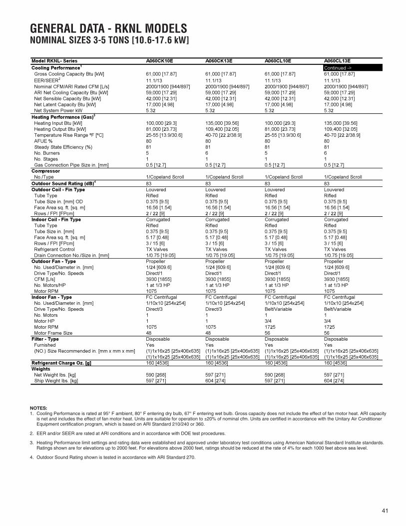
41
GENERAL DATA - RKNL MODELSNOMINAL SIZES 3-5 TONS [10.6-17.6 kW]
Model RKNL- Series A060CK10E A060CK13E A060CL10E A060CL13ECooling Performance1 Continued -> Gross Cooling Capacity Btu [kW] 61,000 [17.87] 61,000 [17.87] 61,000 [17.87] 61,000 [17.87] EER/SEER2 11.1/13 11.1/13 11.1/13 11.1/13 Nominal CFM/ARI Rated CFM [L/s] 2000/1900 [944/897] 2000/1900 [944/897] 2000/1900 [944/897] 2000/1900 [944/897] ARI Net Cooling Capacity Btu [kW] 59,000 [17.29] 59,000 [17.29] 59,000 [17.29] 59,000 [17.29] Net Sensible Capacity Btu [kW] 42,000 [12.31] 42,000 [12.31] 42,000 [12.31] 42,000 [12.31] Net Latent Capacity Btu [kW] 17,000 [4.98] 17,000 [4.98] 17,000 [4.98] 17,000 [4.98] Net System Power kW 5.32 5.32 5.32 5.32Heating Performance (Gas) Heating Input Btu [kW] 100,000 [29.3] 135,000 [39.56] 100,000 [29.3] 135,000 [39.56] Heating Output Btu [kW] 81,000 [23.73] 109,400 [32.05] 81,000 [23.73] 109,400 [32.05] Temperature Rise Range ºF [ºC] 25-55 [13.9/30.6] 40-70 [22.2/38.9] 25-55 [13.9/30.6] 40-70 [22.2/38.9]
80 80 80 80 Steady State Efficiency (%) 81 81 81 81 No. Burners 5 6 5 6 No. Stages 1 1 1 1 Gas Connection Pipe Size in. [mm] 0.5 [12.7] 0.5 [12.7] 0.5 [12.7] 0.5 [12.7]Compressor No./Type 1/Copeland Scroll 1/Copeland Scroll 1/Copeland Scroll 1/Copeland ScrollOutdoor Sound Rating (dB) 83 83 83 83Outdoor Coil - Fin Type Louvered Louvered Louvered Louvered Tube Type Rifled Rifled Rifled Rifled Tube Size in. [mm] OD 0.375 [9.5] 0.375 [9.5] 0.375 [9.5] 0.375 [9.5] Face Area sq. ft. [sq. m] 16.56 [1.54] 16.56 [1.54] 16.56 [1.54] 16.56 [1.54] Rows / FPI [FPcm] 2 / 22 [9] 2 / 22 [9] 2 / 22 [9] 2 / 22 [9]Indoor Coil - Fin Type Corrugated Corrugated Corrugated Corrugated Tube Type Rifled Rifled Rifled Rifled Tube Size in. [mm] 0.375 [9.5] 0.375 [9.5] 0.375 [9.5] 0.375 [9.5] Face Area sq. ft. [sq. m] 5.17 [0.48] 5.17 [0.48] 5.17 [0.48] 5.17 [0.48] Rows / FPI [FPcm] 3 / 15 [6] 3 / 15 [6] 3 / 15 [6] 3 / 15 [6] Refrigerant Control TX Valves TX Valves TX Valves TX Valves Drain Connection No./Size in. [mm] 1/0.75 [19.05] 1/0.75 [19.05] 1/0.75 [19.05] 1/0.75 [19.05]Outdoor Fan - Type Propeller Propeller Propeller Propeller No. Used/Diameter in. [mm] 1/24 [609.6] 1/24 [609.6] 1/24 [609.6] 1/24 [609.6] Drive Type/No. Speeds Direct/1 Direct/1 Direct/1 Direct/1 CFM [L/s] 3930 [1855] 3930 [1855] 3930 [1855] 3930 [1855] No. Motors/HP 1 at 1/3 HP 1 at 1/3 HP 1 at 1/3 HP 1 at 1/3 HP Motor RPM 1075 1075 1075 1075Indoor Fan - Type FC Centrifugal FC Centrifugal FC Centrifugal FC Centrifugal No. Used/Diameter in. [mm] 1/10x10 [254x254] 1/10x10 [254x254] 1/10x10 [254x254] 1/10x10 [254x254] Drive Type/No. Speeds Direct/3 Direct/3 Belt/Variable Belt/Variable No. Motors 1 1 1 1 Motor HP 1 1 3/4 3/4 Motor RPM 1075 1075 1725 1725 Motor Frame Size 48 48 56 56Filter - Type Disposable Disposable Disposable Disposable Furnished Yes Yes Yes Yes (NO.) Size Recommended in. [mm x mm x mm] (1)1x16x25 [25x406x635] (1)1x16x25 [25x406x635] (1)1x16x25 [25x406x635] (1)1x16x25 [25x406x635]
(1)1x16x25 [25x406x635] (1)1x16x25 [25x406x635] (1)1x16x25 [25x406x635] (1)1x16x25 [25x406x635]Refrigerant Charge Oz. [g] 160 [4536] 160 [4536] 160 [4536] 160 [4536]Weights Net Weight lbs. [kg] 590 [268] 597 [271] 590 [268] 597 [271] Ship Weight lbs. [kg] 597 [271] 604 [274] 597 [271] 604 [274]
3
4
AFUE %
NOTES:1. Cooling Performance is rated at 95° F ambient, 80° F entering dry bulb, 67° F entering wet bulb. Gross capacity does not include the effect of fan motor heat. ARI capacity
is net and includes the effect of fan motor heat. Units are suitable for operation to ±20% of nominal cfm. Units are certified in accordance with the Unitary Air ConditionerEquipment certification program, which is based on ARI Standard 210/240 or 360.
2. EER and/or SEER are rated at ARI conditions and in accordance with DOE test procedures.
3. Heating Performance limit settings and rating data were established and approved under laboratory test conditions using American National Standard Institute standards.Ratings shown are for elevations up to 2000 feet. For elevations above 2000 feet, ratings should be reduced at the rate of 4% for each 1000 feet above sea level.
4. Outdoor Sound Rating shown is tested in accordance with ARI Standard 270.

42
GENERAL DATA - RKNL MODELSNOMINAL SIZES 3-5 TONS [10.6-17.6 kW]
Model RKNL- Series A060CM10E A060CM13E A060DL10E A060DL13ECooling Performance1 Continued -> Gross Cooling Capacity Btu [kW] 61,000 [17.87] 61,000 [17.87] 61,000 [17.87] 61,000 [17.87] EER/SEER2 11.1/13 11.1/13 11.1/13 11.1/13 Nominal CFM/ARI Rated CFM [L/s] 2000/1900 [944/897] 2000/1900 [944/897] 2000/1900 [944/897] 2000/1900 [944/897] ARI Net Cooling Capacity Btu [kW] 59,000 [17.29] 59,000 [17.29] 59,000 [17.29] 59,000 [17.29] Net Sensible Capacity Btu [kW] 42,000 [12.31] 42,000 [12.31] 42,000 [12.31] 42,000 [12.31] Net Latent Capacity Btu [kW] 17,000 [4.98] 17,000 [4.98] 17,000 [4.98] 17,000 [4.98] Net System Power kW 5.32 5.32 5.32 5.32Heating Performance (Gas) Heating Input Btu [kW] 100,000 [29.3] 135,000 [39.56] 100,000 [29.3] 135,000 [39.56] Heating Output Btu [kW] 81,000 [23.73] 109,400 [32.05] 81,000 [23.73] 109,400 [32.05] Temperature Rise Range ºF [ºC] 25-55 [13.9/30.6] 40-70 [22.2/38.9] 25-55 [13.9/30.6] 40-70 [22.2/38.9]
80 80 80 80 Steady State Efficiency (%) 81 81 81 81 No. Burners 5 6 5 6 No. Stages 1 1 1 1 Gas Connection Pipe Size in. [mm] 0.5 [12.7] 0.5 [12.7] 0.5 [12.7] 0.5 [12.7]Compressor No./Type 1/Copeland Scroll 1/Copeland Scroll 1/Copeland Scroll 1/Copeland ScrollOutdoor Sound Rating (dB) 83 83 83 83Outdoor Coil - Fin Type Louvered Louvered Louvered Louvered Tube Type Rifled Rifled Rifled Rifled Tube Size in. [mm] OD 0.375 [9.5] 0.375 [9.5] 0.375 [9.5] 0.375 [9.5] Face Area sq. ft. [sq. m] 16.56 [1.54] 16.56 [1.54] 16.56 [1.54] 16.56 [1.54] Rows / FPI [FPcm] 2 / 22 [9] 2 / 22 [9] 2 / 22 [9] 2 / 22 [9]Indoor Coil - Fin Type Corrugated Corrugated Corrugated Corrugated Tube Type Rifled Rifled Rifled Rifled Tube Size in. [mm] 0.375 [9.5] 0.375 [9.5] 0.375 [9.5] 0.375 [9.5] Face Area sq. ft. [sq. m] 5.17 [0.48] 5.17 [0.48] 5.17 [0.48] 5.17 [0.48] Rows / FPI [FPcm] 3 / 15 [6] 3 / 15 [6] 3 / 15 [6] 3 / 15 [6] Refrigerant Control TX Valves TX Valves TX Valves TX Valves Drain Connection No./Size in. [mm] 1/0.75 [19.05] 1/0.75 [19.05] 1/0.75 [19.05] 1/0.75 [19.05]Outdoor Fan - Type Propeller Propeller Propeller Propeller No. Used/Diameter in. [mm] 1/24 [609.6] 1/24 [609.6] 1/24 [609.6] 1/24 [609.6] Drive Type/No. Speeds Direct/1 Direct/1 Direct/1 Direct/1 CFM [L/s] 3930 [1855] 3930 [1855] 3930 [1855] 3930 [1855] No. Motors/HP 1 at 1/3 HP 1 at 1/3 HP 1 at 1/3 HP 1 at 1/3 HP Motor RPM 1075 1075 1075 1075Indoor Fan - Type FC Centrifugal FC Centrifugal FC Centrifugal FC Centrifugal No. Used/Diameter in. [mm] 1/10x10 [254x254] 1/10x10 [254x254] 1/10x10 [254x254] 1/10x10 [254x254] Drive Type/No. Speeds Belt/Variable Belt/Variable Belt/Variable Belt/Variable No. Motors 1 1 1 1 Motor HP 1 1 3/4 3/4 Motor RPM 1725 1725 1725 1725 Motor Frame Size 56 56 56 56Filter - Type Disposable Disposable Disposable Disposable Furnished Yes Yes Yes Yes (NO.) Size Recommended in. [mm x mm x mm] (1)1x16x25 [25x406x635] (1)1x16x25 [25x406x635] (1)1x16x25 [25x406x635] (1)1x16x25 [25x406x635]
(1)1x16x25 [25x406x635] (1)1x16x25 [25x406x635] (1)1x16x25 [25x406x635] (1)1x16x25 [25x406x635]Refrigerant Charge Oz. [g] 160 [4536] 160 [4536] 160 [4536] 160 [4536]Weights Net Weight lbs. [kg] 590 [268] 590 [268] 590 [268] 597 [271] Ship Weight lbs. [kg] 597 [271] 597 [271] 597 [271] 604 [274]
3
4
AFUE %
NOTES:1. Cooling Performance is rated at 95° F ambient, 80° F entering dry bulb, 67° F entering wet bulb. Gross capacity does not include the effect of fan motor heat. ARI capacity
is net and includes the effect of fan motor heat. Units are suitable for operation to ±20% of nominal cfm. Units are certified in accordance with the Unitary Air ConditionerEquipment certification program, which is based on ARI Standard 210/240 or 360.
2. EER and/or SEER are rated at ARI conditions and in accordance with DOE test procedures.
3. Heating Performance limit settings and rating data were established and approved under laboratory test conditions using American National Standard Institute standards.Ratings shown are for elevations up to 2000 feet. For elevations above 2000 feet, ratings should be reduced at the rate of 4% for each 1000 feet above sea level.
4. Outdoor Sound Rating shown is tested in accordance with ARI Standard 270.

43
GENERAL DATA - RKNL MODELSNOMINAL SIZES 3-5 TONS [10.6-17.6 kW]
Model RKNL- Series A060DM10E A060DM13E A060JK10E A060JK10XCooling Performance1 Continued -> Gross Cooling Capacity Btu [kW] 61,000 [17.87] 61,000 [17.87] 61,000 [17.87] 61,000 [17.87] EER/SEER2 11.1/13 11.1/13 11.1/13 11.1/13 Nominal CFM/ARI Rated CFM [L/s] 2000/1900 [944/897] 2000/1900 [944/897] 2000/1900 [944/897] 2000/1900 [944/897] ARI Net Cooling Capacity Btu [kW] 59,000 [17.29] 59,000 [17.29] 59,000 [17.29] 59,000 [17.29] Net Sensible Capacity Btu [kW] 42,000 [12.31] 42,000 [12.31] 42,000 [12.31] 42,000 [12.31] Net Latent Capacity Btu [kW] 17,000 [4.98] 17,000 [4.98] 17,000 [4.98] 17,000 [4.98] Net System Power kW 5.32 5.32 5.32 5.32Heating Performance (Gas) Heating Input Btu [kW] 100,000 [29.3] 135,000 [39.56] 100,000 [29.3] 100,000 [29.3] Heating Output Btu [kW] 81,000 [23.73] 109,400 [32.05] 78,500 [23] 78,500 [23] Temperature Rise Range ºF [ºC] 40-70 [22.2/38.9] 25-55 [13.9/30.6] 25-55 [13.9/30.6]
80 80 80 80 Steady State Efficiency (%) 81 81 81 81 No. Burners 5 6 5 5 No. Stages 1 1 1 1 Gas Connection Pipe Size in. [mm] 0.5 [12.7] 0.5 [12.7] 0.5 [12.7] 0.5 [12.7]Compressor No./Type 1/Copeland Scroll 1/Copeland Scroll 1/Copeland Scroll 1/Copeland ScrollOutdoor Sound Rating (dB) 83 83 83 83Outdoor Coil - Fin Type Louvered Louvered Louvered Louvered Tube Type Rifled Rifled Rifled Rifled Tube Size in. [mm] OD 0.375 [9.5] 0.375 [9.5] 0.375 [9.5] 0.375 [9.5] Face Area sq. ft. [sq. m] 16.56 [1.54] 16.56 [1.54] 16.56 [1.54] 16.56 [1.54] Rows / FPI [FPcm] 2 / 22 [9] 2 / 22 [9] 2 / 22 [9] 2 / 22 [9]Indoor Coil - Fin Type Corrugated Corrugated Corrugated Corrugated Tube Type Rifled Rifled Rifled Rifled Tube Size in. [mm] 0.375 [9.5] 0.375 [9.5] 0.375 [9.5] 0.375 [9.5] Face Area sq. ft. [sq. m] 5.17 [0.48] 5.17 [0.48] 5.17 [0.48] 5.17 [0.48] Rows / FPI [FPcm] 3 / 15 [6] 3 / 15 [6] 3 / 15 [6] 3 / 15 [6] Refrigerant Control TX Valves TX Valves TX Valves TX Valves Drain Connection No./Size in. [mm] 1/0.75 [19.05] 1/0.75 [19.05] 1/0.75 [19.05] 1/0.75 [19.05]Outdoor Fan - Type Propeller Propeller Propeller Propeller No. Used/Diameter in. [mm] 1/24 [609.6] 1/24 [609.6] 1/24 [609.6] 1/24 [609.6] Drive Type/No. Speeds Direct/1 Direct/1 Direct/1 Direct/1 CFM [L/s] 3930 [1855] 3930 [1855] 3930 [1855] 3930 [1855] No. Motors/HP 1 at 1/3 HP 1 at 1/3 HP 1 at 1/3 HP 1 at 1/3 HP Motor RPM 1075 1075 1075 1075Indoor Fan - Type FC Centrifugal FC Centrifugal FC Centrifugal FC Centrifugal No. Used/Diameter in. [mm] 1/10x10 [254x254] 1/10x10 [254x254] 1/10x10 [254x254] 1/10x10 [254x254] Drive Type/No. Speeds Belt/Variable Belt/Variable Direct/3 Direct/3 No. Motors 1 1 1 1 Motor HP 1 1 1 1 Motor RPM 1725 1725 1075 1075 Motor Frame Size 56 56 48 48Filter - Type Disposable Disposable Disposable Disposable Furnished Yes Yes Yes Yes (NO.) Size Recommended in. [mm x mm x mm] (1)1x16x25 [25x406x635] (1)1x16x25 [25x406x635] (1)1x16x25 [25x406x635] (1)1x16x25 [25x406x635]
(1)1x16x25 [25x406x635] (1)1x16x25 [25x406x635] (1)1x16x25 [25x406x635] (1)1x16x25 [25x406x635]Refrigerant Charge Oz. [g] 160 [4536] 160 [4536] 160 [4536] 160 [4536]Weights Net Weight lbs. [kg] 590 [268] 590 [268] 590 [268] 590 [268] Ship Weight lbs. [kg] 597 [271] 597 [271] 597 [271] 597 [271]
3
4
25-55 [13.9/30.6] AFUE %
NOTES:1. Cooling Performance is rated at 95° F ambient, 80° F entering dry bulb, 67° F entering wet bulb. Gross capacity does not include the effect of fan motor heat. ARI capacity
is net and includes the effect of fan motor heat. Units are suitable for operation to ±20% of nominal cfm. Units are certified in accordance with the Unitary Air ConditionerEquipment certification program, which is based on ARI Standard 210/240 or 360.
2. EER and/or SEER are rated at ARI conditions and in accordance with DOE test procedures.
3. Heating Performance limit settings and rating data were established and approved under laboratory test conditions using American National Standard Institute standards.Ratings shown are for elevations up to 2000 feet. For elevations above 2000 feet, ratings should be reduced at the rate of 4% for each 1000 feet above sea level.
4. Outdoor Sound Rating shown is tested in accordance with ARI Standard 270.

44
GENERAL DATA - RKNL MODELSNOMINAL SIZES 3-5 TONS [10.6-17.6 kW]
Model RKNL- Series A060JK13E A060JK13XCooling Performance1
Gross Cooling Capacity Btu [kW] 61,000 [17.87] 61,000 [17.87] EER/SEER2 11.1/13 11.1/13 Nominal CFM/ARI Rated CFM [L/s] 2000/1900 [944/897] 2000/1900 [944/897] ARI Net Cooling Capacity Btu [kW] 59,000 [17.29] 59,000 [17.29] Net Sensible Capacity Btu [kW] 42,000 [12.31] 42,000 [12.31] Net Latent Capacity Btu [kW] 17,000 [4.98] 17,000 [4.98] Net System Power kW 5.32 5.32Heating Performance (Gas) Heating Input Btu [kW] 135,000 [39.56] 135,000 [39.56] Heating Output Btu [kW] 106,500 [31.2] 106,500 [31.2] Temperature Rise Range ºF [ºC] 40-70 [22.2/38.9] 40-70 [22.2/38.9]
80 80 Steady State Efficiency (%) 81 81 No. Burners 6 6 No. Stages 1 1
0.5 [12.7] 0.5 [12.7]Compressor No./Type 1/Copeland Scroll 1/Copeland ScrollOutdoor Sound Rating (dB) 83 83Outdoor Coil - Fin Type Louvered Louvered Tube Type Rifled Rifled Tube Size in. [mm] OD 0.375 [9.5] 0.375 [9.5] Face Area sq. ft. [sq. m] 16.56 [1.54] 16.56 [1.54] Rows / FPI [FPcm] 2 / 22 [9] 2 / 22 [9]Indoor Coil - Fin Type Corrugated Corrugated Tube Type Rifled Rifled Tube Size in. [mm] 0.375 [9.5] 0.375 [9.5] Face Area sq. ft. [sq. m] 5.17 [0.48] 5.17 [0.48] Rows / FPI [FPcm] 3 / 15 [6] 3 / 15 [6] Refrigerant Control TX Valves TX Valves Drain Connection No./Size in. [mm] 1/0.75 [19.05] 1/0.75 [19.05]Outdoor Fan - Type Propeller Propeller No. Used/Diameter in. [mm] 1/24 [609.6] 1/24 [609.6] Drive Type/No. Speeds Direct/1 Direct/1 CFM [L/s] 3930 [1855] 3930 [1855] No. Motors/HP 1 at 1/3 HP 1 at 1/3 HP Motor RPM 1075 1075Indoor Fan - Type FC Centrifugal FC Centrifugal No. Used/Diameter in. [mm] 1/10x10 [254x254] 1/10x10 [254x254] Drive Type/No. Speeds Direct/3 Direct/3 No. Motors 1 1 Motor HP 1 1 Motor RPM 1075 1075 Motor Frame Size 48 48Filter - Type Disposable Disposable Furnished Yes Yes (NO.) Size Recommended in. [mm x mm x mm] (1)1x16x25 [25x406x635] (1)1x16x25 [25x406x635]
(1)1x16x25 [25x406x635] (1)1x16x25 [25x406x635]Refrigerant Charge Oz. [g] 160 [4536] 160 [4536]Weights Net Weight lbs. [kg] 597 [271] 597 [271] Ship Weight lbs. [kg] 604 [274] 604 [274]
3
4
Gas Connection Pipe Size in. [mm]
AFUE %
NOTES:1. Cooling Performance is rated at 95° F ambient, 80° F entering dry bulb, 67° F entering wet bulb. Gross capacity does not include the effect of fan motor heat. ARI capacity
is net and includes the effect of fan motor heat. Units are suitable for operation to ±20% of nominal cfm. Units are certified in accordance with the Unitary Air ConditionerEquipment certification program, which is based on ARI Standard 210/240 or 360.
2. EER and/or SEER are rated at ARI conditions and in accordance with DOE test procedures.
3. Heating Performance limit settings and rating data were established and approved under laboratory test conditions using American National Standard Institute standards.Ratings shown are for elevations up to 2000 feet. For elevations above 2000 feet, ratings should be reduced at the rate of 4% for each 1000 feet above sea level.
4. Outdoor Sound Rating shown is tested in accordance with ARI Standard 270.

45
GENERAL DATA - RKPL MODELSNOMINAL SIZES 3-5 TONS [10.6-17.6 kW]
Model RKPL- Series A036CK08E A036CK12E A036CL08E A036CL12ECooling Performance1 Continued -> Gross Cooling Capacity Btu [kW] 36,600 [10.72] 36,600 [10.72] 36,600 [10.72] 36,600 [10.72] EER/SEER2 12.05/14 12.05/14 12.05/14 12.05/14 Nominal CFM/ARI Rated CFM [L/s] 1200/1200 [566/566] 1200/1200 [566/566] 1200/1200 [566/566] 1200/1200 [566/566] ARI Net Cooling Capacity Btu [kW] 35,800 [10.49] 35,800 [10.49] 35,800 [10.49] 35,800 [10.49] Net Sensible Capacity Btu [kW] 27,000 [7.91] 27,000 [7.91] 27,000 [7.91] 27,000 [7.91] Net Latent Capacity Btu [kW] 8,800 [2.58] 8,800 [2.58] 8,800 [2.58] 8,800 [2.58] Net System Power kW 2.97 2.97 2.97 2.97Heating Performance (Gas) Heating Input Btu [kW] 80,000 [23.44] 120,000 [35.16] 80,000 [23.44] 120,000 [35.16] Heating Output Btu [kW] 64,800 [18.99] 97,200 [28.48] 64,800 [18.99] 97,200 [28.48] Temperature Rise Range ºF [ºC] 30-60 [16.7/33.3] 50-80 [27.8/44.4] 30-60 [16.7/33.3] 50-80 [27.8/44.4]
80 80 80 80 Steady State Efficiency (%) 81 81 81 81 No. Burners 4 6 4 6 No. Stages 1 1 1 1 Gas Connection Pipe Size in. [mm] 0.5 [12.7] 0.5 [12.7] 0.5 [12.7] 0.5 [12.7]Compressor No./Type 1/Copeland Scroll 1/Copeland Scroll 1/Copeland Scroll 1/Copeland ScrollOutdoor Sound Rating (dB) 78 78 78 78Outdoor Coil - Fin Type Louvered Louvered Louvered Louvered Tube Type Rifled Rifled Rifled Rifled Tube Size in. [mm] OD 0.375 [9.5] 0.375 [9.5] 0.375 [9.5] 0.375 [9.5] Face Area sq. ft. [sq. m] 16.91 [1.57] 16.91 [1.57] 16.91 [1.57] 16.91 [1.57] Rows / FPI [FPcm] 1 / 22 [9] 1 / 22 [9] 1 / 22 [9] 1 / 22 [9]Indoor Coil - Fin Type Corrugated Corrugated Corrugated Corrugated Tube Type Rifled Rifled Rifled Rifled Tube Size in. [mm] 0.375 [9.5] 0.375 [9.5] 0.375 [9.5] 0.375 [9.5] Face Area sq. ft. [sq. m] 5.17 [0.48] 5.17 [0.48] 5.17 [0.48] 5.17 [0.48] Rows / FPI [FPcm] 2 / 17 [7] 2 / 17 [7] 2 / 17 [7] 2 / 17 [7] Refrigerant Control TX Valves TX Valves TX Valves TX Valves Drain Connection No./Size in. [mm] 1/0.75 [19.05] 1/0.75 [19.05] 1/0.75 [19.05] 1/0.75 [19.05]Outdoor Fan - Type Propeller Propeller Propeller Propeller No. Used/Diameter in. [mm] 1/24 [609.6] 1/24 [609.6] 1/24 [609.6] 1/24 [609.6] Drive Type/No. Speeds Direct/1 Direct/1 Direct/1 Direct/1 CFM [L/s] 3680 [1737] 3680 [1737] 3680 [1737] 3680 [1737] No. Motors/HP 1 at 1/3 HP 1 at 1/3 HP 1 at 1/3 HP 1 at 1/3 HP Motor RPM 1075 1075 1075 1075Indoor Fan - Type FC Centrifugal FC Centrifugal FC Centrifugal FC Centrifugal No. Used/Diameter in. [mm] 1/10x10 [254x254] 1/10x10 [254x254] 1/10x10 [254x254] 1/10x10 [254x254] Drive Type/No. Speeds Direct/4 Direct/4 Belt/Variable Belt/Variable No. Motors 1 1 1 1 Motor HP 1/2 1/2 1/2 1/2 Motor RPM 1075 1075 1725 1725 Motor Frame Size 48 48 48 48Filter - Type Disposable Disposable Disposable Disposable Furnished Yes Yes Yes Yes (NO.) Size Recommended in. [mm x mm x mm] (1)1x16x25 [25x406x635] (1)1x16x25 [25x406x635] (1)1x16x25 [25x406x635] (1)1x16x25 [25x406x635]
(1)1x16x25 [25x406x635] (1)1x16x25 [25x406x635] (1)1x16x25 [25x406x635] (1)1x16x25 [25x406x635]Refrigerant Charge Oz. [g] 96 [2722] 96 [2722] 96 [2722] 96 [2722]Weights Net Weight lbs. [kg] 543 [246] 543 [246] 543 [246] 543 [246] Ship Weight lbs. [kg] 550 [249] 550 [249] 550 [249] 550 [249]
3
4
AFUE %
NOTES:1. Cooling Performance is rated at 95° F ambient, 80° F entering dry bulb, 67° F entering wet bulb. Gross capacity does not include the effect of fan motor heat. ARI capacity
is net and includes the effect of fan motor heat. Units are suitable for operation to ±20% of nominal cfm. Units are certified in accordance with the Unitary Air ConditionerEquipment certification program, which is based on ARI Standard 210/240 or 360.
2. EER and/or SEER are rated at ARI conditions and in accordance with DOE test procedures.
3. Heating Performance limit settings and rating data were established and approved under laboratory test conditions using American National Standard Institute standards.Ratings shown are for elevations up to 2000 feet. For elevations above 2000 feet, ratings should be reduced at the rate of 4% for each 1000 feet above sea level.
4. Outdoor Sound Rating shown is tested in accordance with ARI Standard 270.

46
GENERAL DATA - RKPL MODELSNOMINAL SIZES 3-5 TONS [10.6-17.6 kW]
Model RKPL- Series A036CM08E A036CM12E A036DL08E A036DL12ECooling Performance1 Continued -> Gross Cooling Capacity Btu [kW] 36,600 [10.72] 36,600 [10.72] 36,600 [10.72] 36,600 [10.72] EER/SEER2 12.05/14 12.05/14 12.05/14 12.05/14 Nominal CFM/ARI Rated CFM [L/s] 1200/1200 [566/566] 1200/1200 [566/566] 1200/1200 [566/566] 1200/1200 [566/566] ARI Net Cooling Capacity Btu [kW] 35,800 [10.49] 35,800 [10.49] 35,800 [10.49] 35,800 [10.49] Net Sensible Capacity Btu [kW] 27,000 [7.91] 27,000 [7.91] 27,000 [7.91] 27,000 [7.91] Net Latent Capacity Btu [kW] 8,800 [2.58] 8,800 [2.58] 8,800 [2.58] 8,800 [2.58] Net System Power kW 2.97 2.97 2.97 2.97Heating Performance (Gas) Heating Input Btu [kW] 80,000 [23.44] 120,000 [35.16] 80,000 [23.44] 120,000 [35.16] Heating Output Btu [kW] 64,800 [18.99] 97,200 [28.48] 64,800 [18.99] 97,200 [28.48] Temperature Rise Range ºF [ºC] 30-60 [16.7/33.3] 50-80 [27.8/44.4] 30-60 [16.7/33.3] 50-80 [27.8/44.4]
80 80 80 80 Steady State Efficiency (%) 81 81 81 81 No. Burners 4 6 4 6 No. Stages 1 1 1 1 Gas Connection Pipe Size in. [mm] 0.5 [12.7] 0.5 [12.7] 0.5 [12.7] 0.5 [12.7]Compressor No./Type 1/Copeland Scroll 1/Copeland Scroll 1/Copeland Scroll 1/Copeland ScrollOutdoor Sound Rating (dB) 78 78 78 78Outdoor Coil - Fin Type Louvered Louvered Louvered Louvered Tube Type Rifled Rifled Rifled Rifled Tube Size in. [mm] OD 0.375 [9.5] 0.375 [9.5] 0.375 [9.5] 0.375 [9.5] Face Area sq. ft. [sq. m] 16.91 [1.57] 16.91 [1.57] 16.91 [1.57] 16.91 [1.57] Rows / FPI [FPcm] 1 / 22 [9] 1 / 22 [9] 1 / 22 [9] 1 / 22 [9]Indoor Coil - Fin Type Corrugated Corrugated Corrugated Corrugated Tube Type Rifled Rifled Rifled Rifled Tube Size in. [mm] 0.375 [9.5] 0.375 [9.5] 0.375 [9.5] 0.375 [9.5] Face Area sq. ft. [sq. m] 5.17 [0.48] 5.17 [0.48] 5.17 [0.48] 5.17 [0.48] Rows / FPI [FPcm] 2 / 17 [7] 2 / 17 [7] 2 / 17 [7] 2 / 17 [7] Refrigerant Control TX Valves TX Valves TX Valves TX Valves Drain Connection No./Size in. [mm] 1/0.75 [19.05] 1/0.75 [19.05] 1/0.75 [19.05] 1/0.75 [19.05]Outdoor Fan - Type Propeller Propeller Propeller Propeller No. Used/Diameter in. [mm] 1/24 [609.6] 1/24 [609.6] 1/24 [609.6] 1/24 [609.6] Drive Type/No. Speeds Direct/1 Direct/1 Direct/1 Direct/1 CFM [L/s] 3680 [1737] 3680 [1737] 3680 [1737] 3680 [1737] No. Motors/HP 1 at 1/3 HP 1 at 1/3 HP 1 at 1/3 HP 1 at 1/3 HP Motor RPM 1075 1075 1075 1075Indoor Fan - Type FC Centrifugal FC Centrifugal FC Centrifugal FC Centrifugal No. Used/Diameter in. [mm] 1/10x10 [254x254] 1/10x10 [254x254] 1/10x10 [254x254] 1/10x10 [254x254] Drive Type/No. Speeds Belt/Variable Belt/Variable Belt/Variable Belt/Variable No. Motors 1 1 1 1 Motor HP 1/2 1/2 1/2 1/2 Motor RPM 1725 1725 1725 1725 Motor Frame Size 48 48 48 48Filter - Type Disposable Disposable Disposable Disposable Furnished Yes Yes Yes Yes (NO.) Size Recommended in. [mm x mm x mm] (1)1x16x25 [25x406x635] (1)1x16x25 [25x406x635] (1)1x16x25 [25x406x635] (1)1x16x25 [25x406x635]
(1)1x16x25 [25x406x635] (1)1x16x25 [25x406x635] (1)1x16x25 [25x406x635] (1)1x16x25 [25x406x635]Refrigerant Charge Oz. [g] 96 [2722] 96 [2722] 96 [2722] 96 [2722]Weights Net Weight lbs. [kg] 543 [246] 543 [246] 543 [246] 543 [246] Ship Weight lbs. [kg] 550 [249] 550 [249] 550 [249] 550 [249]
3
4
AFUE %
NOTES:1. Cooling Performance is rated at 95° F ambient, 80° F entering dry bulb, 67° F entering wet bulb. Gross capacity does not include the effect of fan motor heat. ARI capacity
is net and includes the effect of fan motor heat. Units are suitable for operation to ±20% of nominal cfm. Units are certified in accordance with the Unitary Air ConditionerEquipment certification program, which is based on ARI Standard 210/240 or 360.
2. EER and/or SEER are rated at ARI conditions and in accordance with DOE test procedures.
3. Heating Performance limit settings and rating data were established and approved under laboratory test conditions using American National Standard Institute standards.Ratings shown are for elevations up to 2000 feet. For elevations above 2000 feet, ratings should be reduced at the rate of 4% for each 1000 feet above sea level.
4. Outdoor Sound Rating shown is tested in accordance with ARI Standard 270.

47
GENERAL DATA - RKPL MODELSNOMINAL SIZES 3-5 TONS [10.6-17.6 kW]
Model RKPL- Series A036DM08E A036DM12E A036JK08E A036JK08XCooling Performance1 Continued -> Gross Cooling Capacity Btu [kW] 36,600 [10.72] 36,600 [10.72] 36,600 [10.72] 36,600 [10.72] EER/SEER2 12.05/14 12.05/14 12.05/14 12.05/14 Nominal CFM/ARI Rated CFM [L/s] 1200/1200 [566/566] 1200/1200 [566/566] 1200/1200 [566/566] 1200/1200 [566/566] ARI Net Cooling Capacity Btu [kW] 35,800 [10.49] 35,800 [10.49] 35,800 [10.49] 35,800 [10.49] Net Sensible Capacity Btu [kW] 27,000 [7.91] 27,000 [7.91] 27,000 [7.91] 27,000 [7.91] Net Latent Capacity Btu [kW] 8,800 [2.58] 8,800 [2.58] 8,800 [2.58] 8,800 [2.58] Net System Power kW 2.97 2.97 2.97 2.97Heating Performance (Gas) Heating Input Btu [kW] 80,000 [23.44] 120,000 [35.16] 80,000 [23.44] 80,000 [23.44] Heating Output Btu [kW] 64,800 [18.99] 97,200 [28.48] 62,500 [18.31] 62,500 [18.31] Temperature Rise Range ºF [ºC] 30-60 [16.7/33.3] 50-80 [27.8/44.4] 30-60 [16.7/33.3] 30-60 [16.7/33.3]
80 80 80 80 Steady State Efficiency (%) 81 81 81 81 No. Burners 4 6 4 4 No. Stages 1 1 1 1 Gas Connection Pipe Size in. [mm] 0.5 [12.7] 0.5 [12.7] 0.5 [12.7] 0.5 [12.7]Compressor No./Type 1/Copeland Scroll 1/Copeland Scroll 1/Copeland Scroll 1/Copeland ScrollOutdoor Sound Rating (dB) 78 78 78 78Outdoor Coil - Fin Type Louvered Louvered Louvered Louvered Tube Type Rifled Rifled Rifled Rifled Tube Size in. [mm] OD 0.375 [9.5] 0.375 [9.5] 0.375 [9.5] 0.375 [9.5] Face Area sq. ft. [sq. m] 16.91 [1.57] 16.91 [1.57] 16.91 [1.57] 16.91 [1.57] Rows / FPI [FPcm] 1 / 22 [9] 1 / 22 [9] 1 / 22 [9] 1 / 22 [9]Indoor Coil - Fin Type Corrugated Corrugated Corrugated Corrugated Tube Type Rifled Rifled Rifled Rifled Tube Size in. [mm] 0.375 [9.5] 0.375 [9.5] 0.375 [9.5] 0.375 [9.5] Face Area sq. ft. [sq. m] 5.17 [0.48] 5.17 [0.48] 5.17 [0.48] 5.17 [0.48] Rows / FPI [FPcm] 2 / 17 [7] 2 / 17 [7] 2 / 17 [7] 2 / 17 [7] Refrigerant Control TX Valves TX Valves TX Valves TX Valves Drain Connection No./Size in. [mm] 1/0.75 [19.05] 1/0.75 [19.05] 1/0.75 [19.05] 1/0.75 [19.05]Outdoor Fan - Type Propeller Propeller Propeller Propeller No. Used/Diameter in. [mm] 1/24 [609.6] 1/24 [609.6] 1/24 [609.6] 1/24 [609.6] Drive Type/No. Speeds Direct/1 Direct/1 Direct/1 Direct/1 CFM [L/s] 3680 [1737] 3680 [1737] 3680 [1737] 3680 [1737] No. Motors/HP 1 at 1/3 HP 1 at 1/3 HP 1 at 1/3 HP 1 at 1/3 HP Motor RPM 1075 1075 1075 1075Indoor Fan - Type FC Centrifugal FC Centrifugal FC Centrifugal FC Centrifugal No. Used/Diameter in. [mm] 1/10x10 [254x254] 1/10x10 [254x254] 1/10x10 [254x254] 1/10x10 [254x254] Drive Type/No. Speeds Belt/Variable Belt/Variable Direct/4 Direct/4 No. Motors 1 1 1 1 Motor HP 1/2 1/2 1/2 1/2 Motor RPM 1725 1725 1075 1075 Motor Frame Size 48 48 48 48Filter - Type Disposable Disposable Disposable Disposable Furnished Yes Yes Yes Yes (NO.) Size Recommended in. [mm x mm x mm] (1)1x16x25 [25x406x635] (1)1x16x25 [25x406x635] (1)1x16x25 [25x406x635] (1)1x16x25 [25x406x635]
(1)1x16x25 [25x406x635] (1)1x16x25 [25x406x635] (1)1x16x25 [25x406x635] (1)1x16x25 [25x406x635]Refrigerant Charge Oz. [g] 96 [2722] 96 [2722] 96 [2722] 96 [2722]Weights Net Weight lbs. [kg] 543 [246] 543 [246] 543 [246] 543 [246] Ship Weight lbs. [kg] 550 [249] 550 [249] 550 [249] 550 [249]
3
4
AFUE %
NOTES:1. Cooling Performance is rated at 95° F ambient, 80° F entering dry bulb, 67° F entering wet bulb. Gross capacity does not include the effect of fan motor heat. ARI capacity
is net and includes the effect of fan motor heat. Units are suitable for operation to ±20% of nominal cfm. Units are certified in accordance with the Unitary Air ConditionerEquipment certification program, which is based on ARI Standard 210/240 or 360.
2. EER and/or SEER are rated at ARI conditions and in accordance with DOE test procedures.
3. Heating Performance limit settings and rating data were established and approved under laboratory test conditions using American National Standard Institute standards.Ratings shown are for elevations up to 2000 feet. For elevations above 2000 feet, ratings should be reduced at the rate of 4% for each 1000 feet above sea level.
4. Outdoor Sound Rating shown is tested in accordance with ARI Standard 270.

48
GENERAL DATA - RKPL MODELSNOMINAL SIZES 3-5 TONS [10.6-17.6 kW]
Model RKPL- Series A036JK12E A036JK12X A042CK08E A042CK12ECooling Performance1 Continued -> Gross Cooling Capacity Btu [kW] 36,600 [10.72] 36,600 [10.72] 43,000 [12.6] 43,000 [12.6] EER/SEER2 12.05/14 12.05/14 11.85/14 11.85/14 Nominal CFM/ARI Rated CFM [L/s] 1200/1200 [566/566] 1200/1200 [566/566] 1400/1450 [661/684] 1400/1450 [661/684] ARI Net Cooling Capacity Btu [kW] 35,800 [10.49] 35,800 [10.49] 41,500 [12.16] 41,500 [12.16] Net Sensible Capacity Btu [kW] 27,000 [7.91] 27,000 [7.91] 31,200 [9.14] 31,200 [9.14] Net Latent Capacity Btu [kW] 8,800 [2.58] 8,800 [2.58] 10,300 [3.02] 10,300 [3.02] Net System Power kW 2.97 2.97 3.5 3.5Heating Performance (Gas) Heating Input Btu [kW] 120,000 [35.16] 120,000 [35.16] 80,000 [23.44] 120,000 [35.16] Heating Output Btu [kW] 94,500 [27.69] 94,500 [27.69] 64,800 [18.99] 97,200 [28.48] Temperature Rise Range ºF [ºC] 50-80 [27.8/44.4] 50-80 [27.8/44.4] 30-60 [16.7/33.3] 50-80 [27.8/44.4]
80 80 80 80 Steady State Efficiency (%) 81 81 81 81 No. Burners 6 6 4 6 No. Stages 1 1 1 1 Gas Connection Pipe Size in. [mm] 0.5 [12.7] 0.5 [12.7] 0.5 [12.7] 0.5 [12.7]Compressor No./Type 1/Copeland Scroll 1/Copeland Scroll 1/Copeland Scroll 1/Copeland ScrollOutdoor Sound Rating (dB) 78 78 78 78Outdoor Coil - Fin Type Louvered Louvered Louvered Louvered Tube Type Rifled Rifled Rifled Rifled Tube Size in. [mm] OD 0.375 [9.5] 0.375 [9.5] 0.375 [9.5] 0.375 [9.5] Face Area sq. ft. [sq. m] 16.91 [1.57] 16.91 [1.57] 16.91 [1.57] 16.91 [1.57] Rows / FPI [FPcm] 1 / 22 [9] 1 / 22 [9] 1.53 / 22 [9] 1.53 / 22 [9]Indoor Coil - Fin Type Corrugated Corrugated Corrugated Corrugated Tube Type Rifled Rifled Rifled Rifled Tube Size in. [mm] 0.375 [9.5] 0.375 [9.5] 0.375 [9.5] 0.375 [9.5] Face Area sq. ft. [sq. m] 5.17 [0.48] 5.17 [0.48] 5.17 [0.48] 5.17 [0.48] Rows / FPI [FPcm] 2 / 17 [7] 2 / 17 [7] 3 / 13 [5] 3 / 13 [5] Refrigerant Control TX Valves TX Valves TX Valves TX Valves Drain Connection No./Size in. [mm] 1/0.75 [19.05] 1/0.75 [19.05] 1/0.75 [19.05] 1/0.75 [19.05]Outdoor Fan - Type Propeller Propeller Propeller Propeller No. Used/Diameter in. [mm] 1/24 [609.6] 1/24 [609.6] 1/24 [609.6] 1/24 [609.6] Drive Type/No. Speeds Direct/1 Direct/1 Direct/1 Direct/1 CFM [L/s] 3680 [1737] 3680 [1737] 3680 [1737] 3680 [1737] No. Motors/HP 1 at 1/3 HP 1 at 1/3 HP 1 at 1/3 HP 1 at 1/3 HP Motor RPM 1075 1075 1075 1075Indoor Fan - Type FC Centrifugal FC Centrifugal FC Centrifugal FC Centrifugal No. Used/Diameter in. [mm] 1/10x10 [254x254] 1/10x10 [254x254] 1/10x10 [254x254] 1/10x10 [254x254] Drive Type/No. Speeds Direct/4 Direct/4 Direct/4 Direct/4 No. Motors 1 1 1 1 Motor HP 1/2 1/2 3/4 3/4 Motor RPM 1075 1075 1075 1075 Motor Frame Size 48 48 48 48Filter - Type Disposable Disposable Disposable Disposable Furnished Yes Yes Yes Yes (NO.) Size Recommended in. [mm x mm x mm] (1)1x16x25 [25x406x635] (1)1x16x25 [25x406x635] (1)1x16x25 [25x406x635] (1)1x16x25 [25x406x635]
(1)1x16x25 [25x406x635] (1)1x16x25 [25x406x635] (1)1x16x25 [25x406x635] (1)1x16x25 [25x406x635]Refrigerant Charge Oz. [g] 96 [2722] 96 [2722] 125 [3544] 125 [3544]Weights Net Weight lbs. [kg] 543 [246] 543 [246] 570 [259] 579 [263] Ship Weight lbs. [kg] 550 [249] 550 [249] 577 [262] 586 [266]
3
4
AFUE %
NOTES:1. Cooling Performance is rated at 95° F ambient, 80° F entering dry bulb, 67° F entering wet bulb. Gross capacity does not include the effect of fan motor heat. ARI capacity
is net and includes the effect of fan motor heat. Units are suitable for operation to ±20% of nominal cfm. Units are certified in accordance with the Unitary Air ConditionerEquipment certification program, which is based on ARI Standard 210/240 or 360.
2. EER and/or SEER are rated at ARI conditions and in accordance with DOE test procedures.
3. Heating Performance limit settings and rating data were established and approved under laboratory test conditions using American National Standard Institute standards.Ratings shown are for elevations up to 2000 feet. For elevations above 2000 feet, ratings should be reduced at the rate of 4% for each 1000 feet above sea level.
4. Outdoor Sound Rating shown is tested in accordance with ARI Standard 270.

49
GENERAL DATA - RKPL MODELSNOMINAL SIZES 3-5 TONS [10.6-17.6 kW]
Model RKPL- Series A042CL08E A042CL12E A042CM08E A042CM12ECooling Performance1 Continued -> Gross Cooling Capacity Btu [kW] 43,000 [12.6] 43,000 [12.6] 43,000 [12.6] 43,000 [12.6] EER/SEER2 11.85/14 11.85/14 11.85/14 11.85/14 Nominal CFM/ARI Rated CFM [L/s] 1400/1450 [661/684] 1400/1450 [661/684] 1400/1450 [661/684] 1400/1450 [661/684] ARI Net Cooling Capacity Btu [kW] 41,500 [12.16] 41,500 [12.16] 41,500 [12.16] 41,500 [12.16] Net Sensible Capacity Btu [kW] 31,200 [9.14] 31,200 [9.14] 31,200 [9.14] 31,200 [9.14] Net Latent Capacity Btu [kW] 10,300 [3.02] 10,300 [3.02] 10,300 [3.02] 10,300 [3.02] Net System Power kW 3.5 3.5 3.5 3.5Heating Performance (Gas) Heating Input Btu [kW] 80,000 [23.44] 120,000 [35.16] 80,000 [23.44] 120,000 [35.16] Heating Output Btu [kW] 64,800 [18.99] 97,200 [28.48] 64,800 [18.99] 97,200 [28.48] Temperature Rise Range ºF [ºC] 30-60 [16.7/33.3] 50-80 [27.8/44.4] 30-60 [16.7/33.3] 50-80 [27.8/44.4]
80 80 80 80 Steady State Efficiency (%) 81 81 81 81 No. Burners 4 6 4 6 No. Stages 1 1 1 1 Gas Connection Pipe Size in. [mm] 0.5 [12.7] 0.5 [12.7] 0.5 [12.7] 0.5 [12.7]Compressor No./Type 1/Copeland Scroll 1/Copeland Scroll 1/Copeland Scroll 1/Copeland ScrollOutdoor Sound Rating (dB) 78 78 78 78Outdoor Coil - Fin Type Louvered Louvered Louvered Louvered Tube Type Rifled Rifled Rifled Rifled Tube Size in. [mm] OD 0.375 [9.5] 0.375 [9.5] 0.375 [9.5] 0.375 [9.5] Face Area sq. ft. [sq. m] 16.91 [1.57] 16.91 [1.57] 16.91 [1.57] 16.91 [1.57] Rows / FPI [FPcm] 1.53 / 22 [9] 1.53 / 22 [9] 1.53 / 22 [9] 1.53 / 22 [9]Indoor Coil - Fin Type Corrugated Corrugated Corrugated Corrugated Tube Type Rifled Rifled Rifled Rifled Tube Size in. [mm] 0.375 [9.5] 0.375 [9.5] 0.375 [9.5] 0.375 [9.5] Face Area sq. ft. [sq. m] 5.17 [0.48] 5.17 [0.48] 5.17 [0.48] 5.17 [0.48] Rows / FPI [FPcm] 3 / 13 [5] 3 / 13 [5] 3 / 13 [5] 3 / 13 [5] Refrigerant Control TX Valves TX Valves TX Valves TX Valves Drain Connection No./Size in. [mm] 1/0.75 [19.05] 1/0.75 [19.05] 1/0.75 [19.05] 1/0.75 [19.05]Outdoor Fan - Type Propeller Propeller Propeller Propeller No. Used/Diameter in. [mm] 1/24 [609.6] 1/24 [609.6] 1/24 [609.6] 1/24 [609.6] Drive Type/No. Speeds Direct/1 Direct/1 Direct/1 Direct/1 CFM [L/s] 3680 [1737] 3680 [1737] 3680 [1737] 3680 [1737] No. Motors/HP 1 at 1/3 HP 1 at 1/3 HP 1 at 1/3 HP 1 at 1/3 HP Motor RPM 1075 1075 1075 1075Indoor Fan - Type FC Centrifugal FC Centrifugal FC Centrifugal FC Centrifugal No. Used/Diameter in. [mm] 1/10x10 [254x254] 1/10x10 [254x254] 1/10x10 [254x254] 1/10x10 [254x254] Drive Type/No. Speeds Belt/Variable Belt/Variable Belt/Variable Belt/Variable No. Motors 1 1 1 1 Motor HP 1/2 1/2 1/2 1/2 Motor RPM 1725 1725 1725 1725 Motor Frame Size 48 48 48 48Filter - Type Disposable Disposable Disposable Disposable Furnished Yes Yes Yes Yes (NO.) Size Recommended in. [mm x mm x mm] (1)1x16x25 [25x406x635] (1)1x16x25 [25x406x635] (1)1x16x25 [25x406x635] (1)1x16x25 [25x406x635]
(1)1x16x25 [25x406x635] (1)1x16x25 [25x406x635] (1)1x16x25 [25x406x635] (1)1x16x25 [25x406x635]Refrigerant Charge Oz. [g] 125 [3544] 125 [3544] 125 [3544] 125 [3544]Weights Net Weight lbs. [kg] 570 [259] 579 [263] 570 [259] 570 [259] Ship Weight lbs. [kg] 577 [262] 586 [266] 577 [262] 577 [262]
3
4
AFUE %
NOTES:1. Cooling Performance is rated at 95° F ambient, 80° F entering dry bulb, 67° F entering wet bulb. Gross capacity does not include the effect of fan motor heat. ARI capacity
is net and includes the effect of fan motor heat. Units are suitable for operation to ±20% of nominal cfm. Units are certified in accordance with the Unitary Air ConditionerEquipment certification program, which is based on ARI Standard 210/240 or 360.
2. EER and/or SEER are rated at ARI conditions and in accordance with DOE test procedures.
3. Heating Performance limit settings and rating data were established and approved under laboratory test conditions using American National Standard Institute standards.Ratings shown are for elevations up to 2000 feet. For elevations above 2000 feet, ratings should be reduced at the rate of 4% for each 1000 feet above sea level.
4. Outdoor Sound Rating shown is tested in accordance with ARI Standard 270.

50
GENERAL DATA - RKPL MODELSNOMINAL SIZES 3-5 TONS [10.6-17.6 kW]
Model RKPL- Series A042DL08E A042DL12E A042DM08E A042DM12ECooling Performance1 Continued -> Gross Cooling Capacity Btu [kW] 43,000 [12.6] 43,000 [12.6] 43,000 [12.6] 43,000 [12.6] EER/SEER2 11.85/14 11.85/14 11.85/14 11.85/14 Nominal CFM/ARI Rated CFM [L/s] 1400/1450 [661/684] 1400/1450 [661/684] 1400/1450 [661/684] 1400/1450 [661/684] ARI Net Cooling Capacity Btu [kW] 41,500 [12.16] 41,500 [12.16] 41,500 [12.16] 41,500 [12.16] Net Sensible Capacity Btu [kW] 31,200 [9.14] 31,200 [9.14] 31,200 [9.14] 31,200 [9.14] Net Latent Capacity Btu [kW] 10,300 [3.02] 10,300 [3.02] 10,300 [3.02] 10,300 [3.02] Net System Power kW 3.5 3.5 3.5 3.5Heating Performance (Gas) Heating Input Btu [kW] 80,000 [23.44] 120,000 [35.16] 80,000 [23.44] 120,000 [35.16] Heating Output Btu [kW] 64,800 [18.99] 97,200 [28.48] 64,800 [18.99] 97,200 [28.48] Temperature Rise Range ºF [ºC] 30-60 [16.7/33.3] 50-80 [27.8/44.4] 30-60 [16.7/33.3] 50-80 [27.8/44.4]
80 80 80 80 Steady State Efficiency (%) 81 81 81 81 No. Burners 4 6 4 6 No. Stages 1 1 1 1 Gas Connection Pipe Size in. [mm] 0.5 [12.7] 0.5 [12.7] 0.5 [12.7] 0.5 [12.7]Compressor No./Type 1/Copeland Scroll 1/Copeland Scroll 1/Copeland Scroll 1/Copeland ScrollOutdoor Sound Rating (dB) 78 78 78 78Outdoor Coil - Fin Type Louvered Louvered Louvered Louvered Tube Type Rifled Rifled Rifled Rifled Tube Size in. [mm] OD 0.375 [9.5] 0.375 [9.5] 0.375 [9.5] 0.375 [9.5] Face Area sq. ft. [sq. m] 16.91 [1.57] 16.91 [1.57] 16.91 [1.57] 16.91 [1.57] Rows / FPI [FPcm] 1.53 / 22 [9] 1.53 / 22 [9] 1.53 / 22 [9] 1.53 / 22 [9]Indoor Coil - Fin Type Corrugated Corrugated Corrugated Corrugated Tube Type Rifled Rifled Rifled Rifled Tube Size in. [mm] 0.375 [9.5] 0.375 [9.5] 0.375 [9.5] 0.375 [9.5] Face Area sq. ft. [sq. m] 5.17 [0.48] 5.17 [0.48] 5.17 [0.48] 5.17 [0.48] Rows / FPI [FPcm] 3 / 13 [5] 3 / 13 [5] 3 / 13 [5] 3 / 13 [5] Refrigerant Control TX Valves TX Valves TX Valves TX Valves Drain Connection No./Size in. [mm] 1/0.75 [19.05] 1/0.75 [19.05] 1/0.75 [19.05] 1/0.75 [19.05]Outdoor Fan - Type Propeller Propeller Propeller Propeller No. Used/Diameter in. [mm] 1/24 [609.6] 1/24 [609.6] 1/24 [609.6] 1/24 [609.6] Drive Type/No. Speeds Direct/1 Direct/1 Direct/1 Direct/1 CFM [L/s] 3680 [1737] 3680 [1737] 3680 [1737] 3680 [1737] No. Motors/HP 1 at 1/3 HP 1 at 1/3 HP 1 at 1/3 HP 1 at 1/3 HP Motor RPM 1075 1075 1075 1075Indoor Fan - Type FC Centrifugal FC Centrifugal FC Centrifugal FC Centrifugal No. Used/Diameter in. [mm] 1/10x10 [254x254] 1/10x10 [254x254] 1/10x10 [254x254] 1/10x10 [254x254] Drive Type/No. Speeds Belt/Variable Belt/Variable Belt/Variable Belt/Variable No. Motors 1 1 1 1 Motor HP 1/2 1/2 1/2 1/2 Motor RPM 1725 1725 1725 1725 Motor Frame Size 48 48 48 48Filter - Type Disposable Disposable Disposable Disposable Furnished Yes Yes Yes Yes (NO.) Size Recommended in. [mm x mm x mm] (1)1x16x25 [25x406x635] (1)1x16x25 [25x406x635] (1)1x16x25 [25x406x635] (1)1x16x25 [25x406x635]
(1)1x16x25 [25x406x635] (1)1x16x25 [25x406x635] (1)1x16x25 [25x406x635] (1)1x16x25 [25x406x635]Refrigerant Charge Oz. [g] 125 [3544] 125 [3544] 125 [3544] 125 [3544]Weights Net Weight lbs. [kg] 570 [259] 570 [259] 570 [259] 570 [259] Ship Weight lbs. [kg] 577 [262] 577 [262] 577 [262] 577 [262]
3
4
AFUE %
NOTES:1. Cooling Performance is rated at 95° F ambient, 80° F entering dry bulb, 67° F entering wet bulb. Gross capacity does not include the effect of fan motor heat. ARI capacity
is net and includes the effect of fan motor heat. Units are suitable for operation to ±20% of nominal cfm. Units are certified in accordance with the Unitary Air ConditionerEquipment certification program, which is based on ARI Standard 210/240 or 360.
2. EER and/or SEER are rated at ARI conditions and in accordance with DOE test procedures.
3. Heating Performance limit settings and rating data were established and approved under laboratory test conditions using American National Standard Institute standards.Ratings shown are for elevations up to 2000 feet. For elevations above 2000 feet, ratings should be reduced at the rate of 4% for each 1000 feet above sea level.
4. Outdoor Sound Rating shown is tested in accordance with ARI Standard 270.

51
GENERAL DATA - RKPL MODELSNOMINAL SIZES 3-5 TONS [10.6-17.6 kW]
Model RKPL- Series A042JK08E A042JK08X A042JK12E A042JK12XCooling Performance1 Continued -> Gross Cooling Capacity Btu [kW] 43,000 [12.6] 43,000 [12.6] 43,000 [12.6] 43,000 [12.6] EER/SEER2 11.85/14 11.85/14 11.85/14 11.85/14 Nominal CFM/ARI Rated CFM [L/s] 1400/1450 [661/684] 1400/1450 [661/684] 1400/1450 [661/684] 1400/1450 [661/684] ARI Net Cooling Capacity Btu [kW] 41,500 [12.16] 41,500 [12.16] 41,500 [12.16] 41,500 [12.16]
31,200 [9.14] 31,200 [9.14] 31,200 [9.14] 31,200 [9.14]10,300 [3.02] 10,300 [3.02] 10,300 [3.02] 10,300 [3.02]
Net System Power kW 3.5 3.5 3.5 3.5Heating Performance (Gas) Heating Input Btu [kW] 80,000 [23.44] 80,000 [23.44] 120,000 [35.16] 120,000 [35.16] Heating Output Btu [kW] 62,500 [18.31] 62,500 [18.31] 94,500 [27.69] 94,500 [27.69] Temperature Rise Range ºF [ºC] 30-60 [16.7/33.3] 30-60 [16.7/33.3] 50-80 [27.8/44.4] 50-80 [27.8/44.4]
80 80 80 80 Steady State Efficiency (%) 81 81 81 81 No. Burners 4 4 6 6 No. Stages 1 1 1 1 Gas Connection Pipe Size in. [mm] 0.5 [12.7] 0.5 [12.7] 0.5 [12.7] 0.5 [12.7]Compressor No./Type 1/Copeland Scroll 1/Copeland Scroll 1/Copeland Scroll 1/Copeland ScrollOutdoor Sound Rating (dB) 78 78 78 78Outdoor Coil - Fin Type Louvered Louvered Louvered Louvered Tube Type Rifled Rifled Rifled Rifled Tube Size in. [mm] OD 0.375 [9.5] 0.375 [9.5] 0.375 [9.5] 0.375 [9.5] Face Area sq. ft. [sq. m] 16.91 [1.57] 16.91 [1.57] 16.91 [1.57] 16.91 [1.57] Rows / FPI [FPcm] 1.53 / 22 [9] 1.53 / 22 [9] 1.53 / 22 [9] 1.53 / 22 [9]Indoor Coil - Fin Type Corrugated Corrugated Corrugated Corrugated Tube Type Rifled Rifled Rifled Rifled Tube Size in. [mm] 0.375 [9.5] 0.375 [9.5] 0.375 [9.5] 0.375 [9.5] Face Area sq. ft. [sq. m] 5.17 [0.48] 5.17 [0.48] 5.17 [0.48] 5.17 [0.48] Rows / FPI [FPcm] 3 / 13 [5] 3 / 13 [5] 3 / 13 [5] 3 / 13 [5] Refrigerant Control TX Valves TX Valves TX Valves TX Valves Drain Connection No./Size in. [mm] 1/0.75 [19.05] 1/0.75 [19.05] 1/0.75 [19.05] 1/0.75 [19.05]Outdoor Fan - Type Propeller Propeller Propeller Propeller No. Used/Diameter in. [mm] 1/24 [609.6] 1/24 [609.6] 1/24 [609.6] 1/24 [609.6] Drive Type/No. Speeds Direct/1 Direct/1 Direct/1 Direct/1 CFM [L/s] 3680 [1737] 3680 [1737] 3680 [1737] 3680 [1737] No. Motors/HP 1 at 1/3 HP 1 at 1/3 HP 1 at 1/3 HP 1 at 1/3 HP Motor RPM 1075 1075 1075 1075Indoor Fan - Type FC Centrifugal FC Centrifugal FC Centrifugal FC Centrifugal No. Used/Diameter in. [mm] 1/10x10 [254x254] 1/10x10 [254x254] 1/10x10 [254x254] 1/10x10 [254x254] Drive Type/No. Speeds Direct/4 Direct/4 Direct/4 Direct/4 No. Motors 1 1 1 1 Motor HP 3/4 3/4 3/4 3/4 Motor RPM 1075 1075 1725 1075 Motor Frame Size 48 48 48 48Filter - Type Disposable Disposable Disposable Disposable Furnished Yes Yes Yes Yes (NO.) Size Recommended in. [mm x mm x mm] (1)1x16x25 [25x406x635] (1)1x16x25 [25x406x635] (1)1x16x25 [25x406x635] (1)1x16x25 [25x406x635]
(1)1x16x25 [25x406x635] (1)1x16x25 [25x406x635] (1)1x16x25 [25x406x635] (1)1x16x25 [25x406x635]Refrigerant Charge Oz. [g] 125 [3544] 125 [3544] 125 [3544] 125 [3544]Weights Net Weight lbs. [kg] 570 [259] 570 [259] 579 [263] 579 [263] Ship Weight lbs. [kg] 577 [262] 577 [262] 586 [266] 586 [266]
3
4
Net Latent Capacity Btu [kW] Net Sensible Capacity Btu [kW]
AFUE %
NOTES:1. Cooling Performance is rated at 95° F ambient, 80° F entering dry bulb, 67° F entering wet bulb. Gross capacity does not include the effect of fan motor heat. ARI capacity
is net and includes the effect of fan motor heat. Units are suitable for operation to ±20% of nominal cfm. Units are certified in accordance with the Unitary Air ConditionerEquipment certification program, which is based on ARI Standard 210/240 or 360.
2. EER and/or SEER are rated at ARI conditions and in accordance with DOE test procedures.
3. Heating Performance limit settings and rating data were established and approved under laboratory test conditions using American National Standard Institute standards.Ratings shown are for elevations up to 2000 feet. For elevations above 2000 feet, ratings should be reduced at the rate of 4% for each 1000 feet above sea level.
4. Outdoor Sound Rating shown is tested in accordance with ARI Standard 270.

52
GENERAL DATA - RKPL MODELSNOMINAL SIZES 3-5 TONS [10.6-17.6 kW]
Model RKPL- Series A048CK08E A048CK10E A048CL08ECooling Performance1 Continued -> Gross Cooling Capacity Btu [kW] 50,500 [14.8] 50,500 [14.8] 50,500 [14.8] 50,500 [14.8] EER/SEER2 12.15/14 12.15/14 12.15/14 12.15/14 Nominal CFM/ARI Rated CFM [L/s] 1600/1600 [755/755] 1600/1600 [755/755] 1600/1600 [755/755] 1600/1600 [755/755] ARI Net Cooling Capacity Btu [kW] 49,000 [14.36] 49,000 [14.36] 49,000 [14.36] 49,000 [14.36] Net Sensible Capacity Btu [kW] 36,400 [10.67] 36,400 [10.67] 36,400 [10.67] 36,400 [10.67] Net Latent Capacity Btu [kW] 12,600 [3.69] 12,600 [3.69] 12,600 [3.69] 12,600 [3.69] Net System Power kW 4.03 4.03 4.03 4.03Heating Performance (Gas) Heating Input Btu [kW] 80,000 [23.44] 100,000 [29.3] 135,000 [39.56] 80,000 [23.44] Heating Output Btu [kW] 64,800 [18.99] 81,000 [23.73] 109,400 [32.05] 64,800 [18.99] Temperature Rise Range ºF [ºC] 30-60 [16.7/33.3] 40-70 [22.2/38.9] 50-80 [27.8/44.4] 30-60 [16.7/33.3]
80 80 80 80 Steady State Efficiency (%) 81 81 81 81 No. Burners 4 5 6 4 No. Stages 1 1 1 1 Gas Connection Pipe Size in. [mm] 0.5 [12.7] 0.5 [12.7] 0.5 [12.7] 0.5 [12.7]Compressor No./Type 1/Copeland Scroll 1/Copeland Scroll 1/Copeland Scroll 1/Copeland ScrollOutdoor Sound Rating (dB) 78 78 78 78Outdoor Coil - Fin Type Louvered Louvered Louvered Louvered Tube Type Rifled Rifled Rifled Rifled Tube Size in. [mm] OD 0.375 [9.5] 0.375 [9.5] 0.375 [9.5] 0.375 [9.5] Face Area sq. ft. [sq. m] 16.56 [1.54] 16.56 [1.54] 16.56 [1.54] 16.56 [1.54] Rows / FPI [FPcm] 2 / 22 [9] 2 / 22 [9] 2 / 22 [9] 2 / 22 [9]Indoor Coil - Fin Type Corrugated Corrugated Corrugated Corrugated Tube Type Rifled Rifled Rifled Rifled Tube Size in. [mm] 0.375 [9.5] 0.375 [9.5] 0.375 [9.5] 0.375 [9.5] Face Area sq. ft. [sq. m] 5.17 [0.48] 5.17 [0.48] 5.17 [0.48] 5.17 [0.48] Rows / FPI [FPcm] 3 / 15 [6] 3 / 15 [6] 3 / 15 [6] 3 / 15 [6] Refrigerant Control TX Valves TX Valves TX Valves TX Valves Drain Connection No./Size in. [mm] 1/0.75 [19.05] 1/0.75 [19.05] 1/0.75 [19.05] 1/0.75 [19.05]Outdoor Fan - Type Propeller Propeller Propeller Propeller No. Used/Diameter in. [mm] 1/24 [609.6] 1/24 [609.6] 1/24 [609.6] 1/24 [609.6] Drive Type/No. Speeds Direct/1 Direct/1 Direct/1 Direct/1 CFM [L/s] 3680 [1737] 3680 [1737] 3680 [1737] 3680 [1737] No. Motors/HP 1 at 1/3 HP 1 at 1/3 HP 1 at 1/3 HP 1 at 1/3 HP Motor RPM 1075 1075 1075 1075Indoor Fan - Type FC Centrifugal FC Centrifugal FC Centrifugal FC Centrifugal No. Used/Diameter in. [mm] 1/10x10 [254x254] 1/10x10 [254x254] 1/10x10 [254x254] 1/10x10 [254x254] Drive Type/No. Speeds Direct/4 Direct/4 Direct/4 Belt/Variable No. Motors 1 1 1 1 Motor HP 3/4 3/4 3/4 1/2 Motor RPM 1075 1075 1075 1725 Motor Frame Size 48 48 48 48Filter - Type Disposable Disposable Disposable Disposable Furnished Yes Yes Yes Yes (NO.) Size Recommended in. [mm x mm x mm] (1)1x16x25 [25x406x635] (1)1x16x25 [25x406x635] (1)1x16x25 [25x406x635] (1)1x16x25 [25x406x635]
(1)1x16x25 [25x406x635] (1)1x16x25 [25x406x635] (1)1x16x25 [25x406x635] (1)1x16x25 [25x406x635]Refrigerant Charge Oz. [g] 165 [4678] 165 [4678] 165 [4678] 165 [4678]Weights Net Weight lbs. [kg] 580 [263] 580 [263] 585 [265] 580 [263] Ship Weight lbs. [kg] 587 [266] 587 [266] 592 [269] 587 [266]
3
4
AFUE %
A048CK13E
NOTES:1. Cooling Performance is rated at 95° F ambient, 80° F entering dry bulb, 67° F entering wet bulb. Gross capacity does not include the effect of fan motor heat. ARI capacity
is net and includes the effect of fan motor heat. Units are suitable for operation to ±20% of nominal cfm. Units are certified in accordance with the Unitary Air ConditionerEquipment certification program, which is based on ARI Standard 210/240 or 360.
2. EER and/or SEER are rated at ARI conditions and in accordance with DOE test procedures.
3. Heating Performance limit settings and rating data were established and approved under laboratory test conditions using American National Standard Institute standards.Ratings shown are for elevations up to 2000 feet. For elevations above 2000 feet, ratings should be reduced at the rate of 4% for each 1000 feet above sea level.
4. Outdoor Sound Rating shown is tested in accordance with ARI Standard 270.

53
GENERAL DATA - RKPL MODELSNOMINAL SIZES 3-5 TONS [10.6-17.6 kW]
Model RKPL- Series A048CL10E A048CL13E A048CM08E A048CM10ECooling Performance1 Continued -> Gross Cooling Capacity Btu [kW] 50,500 [14.8] 50,500 [14.8] 50,500 [14.8] 50,500 [14.8] EER/SEER2 12.15/14 12.15/14 12.15/14 12.15/14 Nominal CFM/ARI Rated CFM [L/s] 1600/1600 [755/755] 1600/1600 [755/755] 1600/1600 [755/755] 1600/1600 [755/755] ARI Net Cooling Capacity Btu [kW] 49,000 [14.36] 49,000 [14.36] 49,000 [14.36] 49,000 [14.36] Net Sensible Capacity Btu [kW] 36,400 [10.67] 36,400 [10.67] 36,400 [10.67] 36,400 [10.67] Net Latent Capacity Btu [kW] 12,600 [3.69] 12,600 [3.69] 12,600 [3.69] 12,600 [3.69] Net System Power kW 4.03 4.03 4.03 4.03Heating Performance (Gas) Heating Input Btu [kW] 100,000 [29.3] 135,000 [39.56] 80,000 [23.44] 100,000 [29.3] Heating Output Btu [kW] 81,000 [23.73] 109,400 [32.05] 64,800 [18.99] 81,000 [23.73] Temperature Rise Range ºF [ºC] 30-60 [16.7/33.3] 50-80 [27.8/44.4] 30-60 [16.7/33.3] 30-60 [16.7/33.3]
80 80 80 80 Steady State Efficiency (%) 81 81 81 81 No. Burners 5 6 4 5 No. Stages 1 1 1 1 Gas Connection Pipe Size in. [mm] 0.5 [12.7] 0.5 [12.7] 0.5 [12.7] 0.5 [12.7]Compressor No./Type 1/Copeland Scroll 1/Copeland Scroll 1/Copeland Scroll 1/Copeland ScrollOutdoor Sound Rating (dB) 78 78 78 78Outdoor Coil - Fin Type Louvered Louvered Louvered Louvered Tube Type Rifled Rifled Rifled Rifled Tube Size in. [mm] OD 0.375 [9.5] 0.375 [9.5] 0.375 [9.5] 0.375 [9.5] Face Area sq. ft. [sq. m] 16.56 [1.54] 16.56 [1.54] 16.56 [1.54] 16.56 [1.54] Rows / FPI [FPcm] 2 / 22 [9] 2 / 22 [9] 2 / 22 [9] 2 / 22 [9]Indoor Coil - Fin Type Corrugated Corrugated Corrugated Corrugated Tube Type Rifled Rifled Rifled Rifled Tube Size in. [mm] 0.375 [9.5] 0.375 [9.5] 0.375 [9.5] 0.375 [9.5] Face Area sq. ft. [sq. m] 5.17 [0.48] 5.17 [0.48] 5.17 [0.48] 5.17 [0.48] Rows / FPI [FPcm] 3 / 15 [6] 3 / 15 [6] 3 / 15 [6] 3 / 15 [6] Refrigerant Control TX Valves TX Valves TX Valves TX Valves Drain Connection No./Size in. [mm] 1/0.75 [19.05] 1/0.75 [19.05] 1/0.75 [19.05] 1/0.75 [19.05]Outdoor Fan - Type Propeller Propeller Propeller Propeller No. Used/Diameter in. [mm] 1/24 [609.6] 1/24 [609.6] 1/24 [609.6] 1/24 [609.6] Drive Type/No. Speeds Direct/1 Direct/1 Direct/1 Direct/1 CFM [L/s] 3680 [1737] 3680 [1737] 3680 [1737] 3680 [1737] No. Motors/HP 1 at 1/3 HP 1 at 1/3 HP 1 at 1/3 HP 1 at 1/3 HP Motor RPM 1075 1075 1075 1075Indoor Fan - Type FC Centrifugal FC Centrifugal FC Centrifugal FC Centrifugal No. Used/Diameter in. [mm] 1/10x10 [254x254] 1/10x10 [254x254] 1/10x10 [254x254] 1/10x10 [254x254] Drive Type/No. Speeds Belt/Variable Belt/Variable Belt/Variable Belt/Variable No. Motors 1 1 1 1 Motor HP 1/2 1/2 3/4 3/4 Motor RPM 1725 1725 1725 1725 Motor Frame Size 48 48 56 56Filter - Type Disposable Disposable Disposable Disposable Furnished Yes Yes Yes Yes (NO.) Size Recommended in. [mm x mm x mm] (1)1x16x25 [25x406x635] (1)1x16x25 [25x406x635] (1)1x16x25 [25x406x635] (1)1x16x25 [25x406x635]
(1)1x16x25 [25x406x635] (1)1x16x25 [25x406x635] (1)1x16x25 [25x406x635] (1)1x16x25 [25x406x635]Refrigerant Charge Oz. [g] 165 [4678] 165 [4678] 165 [4678] 165 [4678]Weights Net Weight lbs. [kg] 580 [263] 585 [265] 580 [263] 580 [263] Ship Weight lbs. [kg] 587 [266] 592 [269] 587 [266] 587 [266]
3
4
AFUE %
NOTES:1. Cooling Performance is rated at 95° F ambient, 80° F entering dry bulb, 67° F entering wet bulb. Gross capacity does not include the effect of fan motor heat. ARI capacity
is net and includes the effect of fan motor heat. Units are suitable for operation to ±20% of nominal cfm. Units are certified in accordance with the Unitary Air ConditionerEquipment certification program, which is based on ARI Standard 210/240 or 360.
2. EER and/or SEER are rated at ARI conditions and in accordance with DOE test procedures.
3. Heating Performance limit settings and rating data were established and approved under laboratory test conditions using American National Standard Institute standards.Ratings shown are for elevations up to 2000 feet. For elevations above 2000 feet, ratings should be reduced at the rate of 4% for each 1000 feet above sea level.
4. Outdoor Sound Rating shown is tested in accordance with ARI Standard 270.

54
GENERAL DATA - RKPL MODELSNOMINAL SIZES 3-5 TONS [10.6-17.6 kW]
Model RKPL- Series A048CM13E A048DL08E A048DL10E A048DL13ECooling Performance1 Continued -> Gross Cooling Capacity Btu [kW] 50,500 [14.8] 50,500 [14.8] 50,500 [14.8] 50,500 [14.8] EER/SEER2 12.15/14 12.15/14 12.15/14 12.15/14 Nominal CFM/ARI Rated CFM [L/s] 1600/1600 [755/755] 1600/1600 [755/755] 1600/1600 [755/755] 1600/1600 [755/755] ARI Net Cooling Capacity Btu [kW] 49,000 [14.36] 49,000 [14.36] 49,000 [14.36] 49,000 [14.36] Net Sensible Capacity Btu [kW] 36,400 [10.67] 36,400 [10.67] 36,400 [10.67] 36,400 [10.67] Net Latent Capacity Btu [kW] 12,600 [3.69] 12,600 [3.69] 12,600 [3.69] 12,600 [3.69] Net System Power kW 4.03 4.03 4.03 4.03Heating Performance (Gas) Heating Input Btu [kW] 135,000 [39.56] 80,000 [23.44] 100,000 [29.3] 135,000 [39.56] Heating Output Btu [kW] 109,400 [32.05] 64,800 [18.99] 81,000 [23.73] 109,400 [32.05] Temperature Rise Range ºF [ºC] 50-80 [27.8/44.4] 30-60 [16.7/33.3] 30-60 [16.7/33.3] 50-80 [27.8/44.4]
80 80 80 80 Steady State Efficiency (%) 81 81 81 81 No. Burners 6 4 5 6 No. Stages 1 1 1 1 Gas Connection Pipe Size in. [mm] 0.5 [12.7] 0.5 [12.7] 0.5 [12.7] 0.5 [12.7]Compressor No./Type 1/Copeland Scroll 1/Copeland Scroll 1/Copeland Scroll 1/Copeland ScrollOutdoor Sound Rating (dB) 78 78 78 78Outdoor Coil - Fin Type Louvered Louvered Louvered Louvered Tube Type Rifled Rifled Rifled Rifled Tube Size in. [mm] OD 0.375 [9.5] 0.375 [9.5] 0.375 [9.5] 0.375 [9.5] Face Area sq. ft. [sq. m] 16.56 [1.54] 16.56 [1.54] 16.56 [1.54] 16.56 [1.54] Rows / FPI [FPcm] 2 / 22 [9] 2 / 22 [9] 2 / 22 [9] 2 / 22 [9]Indoor Coil - Fin Type Corrugated Corrugated Corrugated Corrugated Tube Type Rifled Rifled Rifled Rifled Tube Size in. [mm] 0.375 [9.5] 0.375 [9.5] 0.375 [9.5] 0.375 [9.5] Face Area sq. ft. [sq. m] 5.17 [0.48] 5.17 [0.48] 5.17 [0.48] 5.17 [0.48] Rows / FPI [FPcm] 3 / 15 [6] 3 / 15 [6] 3 / 15 [6] 3 / 15 [6] Refrigerant Control TX Valves TX Valves TX Valves TX Valves Drain Connection No./Size in. [mm] 1/0.75 [19.05] 1/0.75 [19.05] 1/0.75 [19.05] 1/0.75 [19.05]Outdoor Fan - Type Propeller Propeller Propeller Propeller No. Used/Diameter in. [mm] 1/24 [609.6] 1/24 [609.6] 1/24 [609.6] 1/24 [609.6] Drive Type/No. Speeds Direct/1 Direct/1 Direct/1 Direct/1 CFM [L/s] 3680 [1737] 3680 [1737] 3680 [1737] 3680 [1737] No. Motors/HP 1 at 1/3 HP 1 at 1/3 HP 1 at 1/3 HP 1 at 1/3 HP Motor RPM 1075 1075 1075 1075Indoor Fan - Type FC Centrifugal FC Centrifugal FC Centrifugal FC Centrifugal No. Used/Diameter in. [mm] 1/10x10 [254x254] 1/10x10 [254x254] 1/10x10 [254x254] 1/10x10 [254x254] Drive Type/No. Speeds Belt/Variable Belt/Variable Belt/Variable Belt/Variable No. Motors 1 1 1 1 Motor HP 3/4 1/2 1/2 1/2 Motor RPM 1725 1725 1725 1725 Motor Frame Size 56 48 48 48Filter - Type Disposable Disposable Disposable Disposable Furnished Yes Yes Yes Yes (NO.) Size Recommended in. [mm x mm x mm] (1)1x16x25 [25x406x635] (1)1x16x25 [25x406x635] (1)1x16x25 [25x406x635] (1)1x16x25 [25x406x635]
(1)1x16x25 [25x406x635] (1)1x16x25 [25x406x635] (1)1x16x25 [25x406x635] (1)1x16x25 [25x406x635]Refrigerant Charge Oz. [g] 165 [4678] 165 [4678] 165 [4678] 165 [4678]Weights Net Weight lbs. [kg] 580 [263] 580 [263] 580 [263] 585 [265] Ship Weight lbs. [kg] 587 [266] 587 [266] 587 [266] 592 [269]
3
4
AFUE %
NOTES:1. Cooling Performance is rated at 95° F ambient, 80° F entering dry bulb, 67° F entering wet bulb. Gross capacity does not include the effect of fan motor heat. ARI capacity
is net and includes the effect of fan motor heat. Units are suitable for operation to ±20% of nominal cfm. Units are certified in accordance with the Unitary Air ConditionerEquipment certification program, which is based on ARI Standard 210/240 or 360.
2. EER and/or SEER are rated at ARI conditions and in accordance with DOE test procedures.
3. Heating Performance limit settings and rating data were established and approved under laboratory test conditions using American National Standard Institute standards.Ratings shown are for elevations up to 2000 feet. For elevations above 2000 feet, ratings should be reduced at the rate of 4% for each 1000 feet above sea level.
4. Outdoor Sound Rating shown is tested in accordance with ARI Standard 270.

55
GENERAL DATA - RKPL MODELSNOMINAL SIZES 3-5 TONS [10.6-17.6 kW]
Model RKPL- Series A048DM08E A048DM10E A048DM13E A048JK08ECooling Performance1 Continued -> Gross Cooling Capacity Btu [kW] 50,500 [14.8] 50,500 [14.8] 50,500 [14.8] 50,500 [14.8] EER/SEER2 12.15/14 12.15/14 12.15/14 12.15/14 Nominal CFM/ARI Rated CFM [L/s] 1600/1600 [755/755] 1600/1600 [755/755] 1600/1600 [755/755] 1600/1600 [755/755] ARI Net Cooling Capacity Btu [kW] 49,000 [14.36] 49,000 [14.36] 49,000 [14.36] 49,000 [14.36] Net Sensible Capacity Btu [kW] 36,400 [10.67] 36,400 [10.67] 36,400 [10.67] 36,400 [10.67] Net Latent Capacity Btu [kW] 12,600 [3.69] 12,600 [3.69] 12,600 [3.69] 12,600 [3.69] Net System Power kW 4.03 4.03 4.03 4.03Heating Performance (Gas) Heating Input Btu [kW] 80,000 [23.44] 100,000 [29.3] 135,000 [39.56] 80,000 [23.44] Heating Output Btu [kW] 64,800 [18.99] 81,000 [23.73] 109,400 [32.05] 62,500 [18.31] Temperature Rise Range ºF [ºC] 30-60 [16.7/33.3] 30-60 [16.7/33.3] 50-80 [27.8/44.4] 30-60 [16.7/33.3]
80 80 80 80 Steady State Efficiency (%) 81 81 81 81 No. Burners 4 5 6 4 No. Stages 1 1 1 1 Gas Connection Pipe Size in. [mm] 0.5 [12.7] 0.5 [12.7] 0.5 [12.7] 0.5 [12.7]Compressor No./Type 1/Copeland Scroll 1/Copeland Scroll 1/Copeland Scroll 1/Copeland ScrollOutdoor Sound Rating (dB) 78 78 78 78Outdoor Coil - Fin Type Louvered Louvered Louvered Louvered Tube Type Rifled Rifled Rifled Rifled Tube Size in. [mm] OD 0.375 [9.5] 0.375 [9.5] 0.375 [9.5] 0.375 [9.5] Face Area sq. ft. [sq. m] 16.56 [1.54] 16.56 [1.54] 16.56 [1.54] 16.56 [1.54] Rows / FPI [FPcm] 2 / 22 [9] 2 / 22 [9] 2 / 22 [9] 2 / 22 [9]Indoor Coil - Fin Type Corrugated Corrugated Corrugated Corrugated Tube Type Rifled Rifled Rifled Rifled Tube Size in. [mm] 0.375 [9.5] 0.375 [9.5] 0.375 [9.5] 0.375 [9.5] Face Area sq. ft. [sq. m] 5.17 [0.48] 5.17 [0.48] 5.17 [0.48] 5.17 [0.48] Rows / FPI [FPcm] 3 / 15 [6] 3 / 15 [6] 3 / 15 [6] 3 / 15 [6] Refrigerant Control TX Valves TX Valves TX Valves TX Valves Drain Connection No./Size in. [mm] 1/0.75 [19.05] 1/0.75 [19.05] 1/0.75 [19.05] 1/0.75 [19.05]Outdoor Fan - Type Propeller Propeller Propeller Propeller No. Used/Diameter in. [mm] 1/24 [609.6] 1/24 [609.6] 1/24 [609.6] 1/24 [609.6] Drive Type/No. Speeds Direct/1 Direct/1 Direct/1 Direct/1 CFM [L/s] 3680 [1737] 3680 [1737] 3680 [1737] 3680 [1737] No. Motors/HP 1 at 1/3 HP 1 at 1/3 HP 1 at 1/3 HP 1 at 1/3 HP Motor RPM 1075 1075 1075 1075Indoor Fan - Type FC Centrifugal FC Centrifugal FC Centrifugal FC Centrifugal No. Used/Diameter in. [mm] 1/10x10 [254x254] 1/10x10 [254x254] 1/10x10 [254x254] 1/10x10 [254x254] Drive Type/No. Speeds Belt/Variable Belt/Variable Belt/Variable Direct/4 No. Motors 1 1 1 1 Motor HP 3/4 3/4 3/4 3/4 Motor RPM 1725 1725 1725 1075 Motor Frame Size 56 56 56 48Filter - Type Disposable Disposable Disposable Disposable Furnished Yes Yes Yes Yes (NO.) Size Recommended in. [mm x mm x mm] (1)1x16x25 [25x406x635] (1)1x16x25 [25x406x635] (1)1x16x25 [25x406x635] (1)1x16x25 [25x406x635]
(1)1x16x25 [25x406x635] (1)1x16x25 [25x406x635] (1)1x16x25 [25x406x635] (1)1x16x25 [25x406x635]Refrigerant Charge Oz. [g] 165 [4678] 165 [4678] 165 [4678] 165 [4678]Weights Net Weight lbs. [kg] 580 [263] 580 [263] 580 [263] 580 [263] Ship Weight lbs. [kg] 587 [266] 587 [266] 587 [266] 587 [266]
3
4
AFUE %
NOTES:1. Cooling Performance is rated at 95° F ambient, 80° F entering dry bulb, 67° F entering wet bulb. Gross capacity does not include the effect of fan motor heat. ARI capacity
is net and includes the effect of fan motor heat. Units are suitable for operation to ±20% of nominal cfm. Units are certified in accordance with the Unitary Air ConditionerEquipment certification program, which is based on ARI Standard 210/240 or 360.
2. EER and/or SEER are rated at ARI conditions and in accordance with DOE test procedures.
3. Heating Performance limit settings and rating data were established and approved under laboratory test conditions using American National Standard Institute standards.Ratings shown are for elevations up to 2000 feet. For elevations above 2000 feet, ratings should be reduced at the rate of 4% for each 1000 feet above sea level.
4. Outdoor Sound Rating shown is tested in accordance with ARI Standard 270.

56
GENERAL DATA - RKPL MODELSNOMINAL SIZES 3-5 TONS [10.6-17.6 kW]
Model RKPL- Series A048JK08X A048JK10E A048JK10X A048JK13ECooling Performance1 Continued -> Gross Cooling Capacity Btu [kW] 50,500 [14.8] 50,500 [14.8] 50,500 [14.8] 50,500 [14.8] EER/SEER2 12.15/14 12.15/14 12.15/14 12.15/14 Nominal CFM/ARI Rated CFM [L/s] 1600/1600 [755/755] 1600/1600 [755/755] 1600/1600 [755/755] 1600/1600 [755/755] ARI Net Cooling Capacity Btu [kW] 49,000 [14.36] 49,000 [14.36] 49,000 [14.36] 49,000 [14.36] Net Sensible Capacity Btu [kW] 36,400 [10.67] 36,400 [10.67] 36,400 [10.67] 36,400 [10.67] Net Latent Capacity Btu [kW] 12,600 [3.69] 12,600 [3.69] 12,600 [3.69] 12,600 [3.69] Net System Power kW 4.03 4.03 4.03 4.03Heating Performance (Gas) Heating Input Btu [kW] 80,000 [23.44] 100,000 [29.3] 100,000 [29.3] 135,000 [39.56] Heating Output Btu [kW] 62,500 [18.31] 78,500 [23] 78,500 [23] 106,500 [31.2] Temperature Rise Range ºF [ºC] 30-60 [16.7/33.3] 40-70 [22.2/38.9] 40-70 [22.2/38.9] 50-80 [27.8/44.4]
80 80 80 80 Steady State Efficiency (%) 81 81 81 81 No. Burners 4 5 5 6 No. Stages 1 1 1 1 Gas Connection Pipe Size in. [mm] 0.5 [12.7] 0.5 [12.7] 0.5 [12.7] 0.5 [12.7]Compressor No./Type 1/Copeland Scroll 1/Copeland Scroll 1/Copeland Scroll 1/Copeland ScrollOutdoor Sound Rating (dB) 78 78 78 78Outdoor Coil - Fin Type Louvered Louvered Louvered Louvered Tube Type Rifled Rifled Rifled Rifled Tube Size in. [mm] OD 0.375 [9.5] 0.375 [9.5] 0.375 [9.5] 0.375 [9.5] Face Area sq. ft. [sq. m] 16.56 [1.54] 16.56 [1.54] 16.56 [1.54] 16.56 [1.54] Rows / FPI [FPcm] 2 / 22 [9] 2 / 22 [9] 2 / 22 [9] 2 / 22 [9]Indoor Coil - Fin Type Corrugated Corrugated Corrugated Corrugated Tube Type Rifled Rifled Rifled Rifled Tube Size in. [mm] 0.375 [9.5] 0.375 [9.5] 0.375 [9.5] 0.375 [9.5] Face Area sq. ft. [sq. m] 5.17 [0.48] 5.17 [0.48] 5.17 [0.48] 5.17 [0.48] Rows / FPI [FPcm] 3 / 15 [6] 3 / 15 [6] 3 / 15 [6] 3 / 15 [6] Refrigerant Control TX Valves TX Valves TX Valves TX Valves Drain Connection No./Size in. [mm] 1/0.75 [19.05] 1/0.75 [19.05] 1/0.75 [19.05] 1/0.75 [19.05]Outdoor Fan - Type Propeller Propeller Propeller Propeller No. Used/Diameter in. [mm] 1/24 [609.6] 1/24 [609.6] 1/24 [609.6] 1/24 [609.6] Drive Type/No. Speeds Direct/1 Direct/1 Direct/1 Direct/1 CFM [L/s] 3680 [1737] 3680 [1737] 3680 [1737] 3680 [1737] No. Motors/HP 1 at 1/3 HP 1 at 1/3 HP 1 at 1/3 HP 1 at 1/3 HP Motor RPM 1075 1075 1075 1075Indoor Fan - Type FC Centrifugal FC Centrifugal FC Centrifugal FC Centrifugal No. Used/Diameter in. [mm] 1/10x10 [254x254] 1/10x10 [254x254] 1/10x10 [254x254] 1/10x10 [254x254] Drive Type/No. Speeds Direct/4 Direct/4 Direct/4 Direct/4 No. Motors 1 1 1 1 Motor HP 3/4 3/4 3/4 3/4 Motor RPM 1075 1075 1075 1075 Motor Frame Size 48 48 48 48Filter - Type Disposable Disposable Disposable Disposable Furnished Yes Yes Yes Yes (NO.) Size Recommended in. [mm x mm x mm] (1)1x16x25 [25x406x635] (1)1x16x25 [25x406x635] (1)1x16x25 [25x406x635] (1)1x16x25 [25x406x635]
(1)1x16x25 [25x406x635] (1)1x16x25 [25x406x635] (1)1x16x25 [25x406x635] (1)1x16x25 [25x406x635]Refrigerant Charge Oz. [g] 165 [4678] 165 [4678] 165 [4678] 165 [4678]Weights Net Weight lbs. [kg] 580 [263] 580 [263] 580 [263] 585 [265] Ship Weight lbs. [kg] 587 [266] 587 [266] 587 [266] 592 [269]
3
4
AFUE %
NOTES:1. Cooling Performance is rated at 95° F ambient, 80° F entering dry bulb, 67° F entering wet bulb. Gross capacity does not include the effect of fan motor heat. ARI capacity
is net and includes the effect of fan motor heat. Units are suitable for operation to ±20% of nominal cfm. Units are certified in accordance with the Unitary Air ConditionerEquipment certification program, which is based on ARI Standard 210/240 or 360.
2. EER and/or SEER are rated at ARI conditions and in accordance with DOE test procedures.
3. Heating Performance limit settings and rating data were established and approved under laboratory test conditions using American National Standard Institute standards.Ratings shown are for elevations up to 2000 feet. For elevations above 2000 feet, ratings should be reduced at the rate of 4% for each 1000 feet above sea level.
4. Outdoor Sound Rating shown is tested in accordance with ARI Standard 270.

57
GENERAL DATA - RKPL MODELSNOMINAL SIZES 3-5 TONS [10.6-17.6 kW]
Model RKPL- Series A048JK13X A060CK10E A060CK13E A060CL10ECooling Performance1 Continued -> Gross Cooling Capacity Btu [kW] 50,500 [14.8] 61,500 [18.02] 61,500 [18.02] 61,500 [18.02] EER/SEER2 12.15/14 12.25/14 12.25/14 12.25/14 Nominal CFM/ARI Rated CFM [L/s] 1600/1600 [755/755] 2000/1850 [944/873] 2000/1850 [944/873] 2000/1850 [944/873] ARI Net Cooling Capacity Btu [kW] 49,000 [14.36] 60,000 [17.58] 60,000 [17.58] 60,000 [17.58] Net Sensible Capacity Btu [kW] 36,400 [10.67] 42,500 [12.45] 42,500 [12.45] 42,500 [12.45] Net Latent Capacity Btu [kW] 12,600 [3.69] 17,500 [5.13] 17,500 [5.13] 17,500 [5.13] Net System Power kW 4.03 4.9 4.9 4.9Heating Performance (Gas) Heating Input Btu [kW] 135,000 [39.56] 100,000 [29.3] 135,000 [39.56] 100,000 [29.3] Heating Output Btu [kW] 106,500 [31.2] 81,000 [23.73] 109,400 [32.05] 81,000 [23.73] Temperature Rise Range ºF [ºC] 50-80 [27.8/44.4] 25-55 [13.9/30.6] 40-70 [22.2/38.9] 25-55 [13.9/30.6]
80 80 80 80 Steady State Efficiency (%) 81 81 81 81 No. Burners 6 5 6 5 No. Stages 1 1 1 1 Gas Connection Pipe Size in. [mm] 0.5 [12.7] 0.5 [12.7] 0.5 [12.7] 0.5 [12.7]Compressor No./Type 1/Copeland Scroll 1/Copeland Scroll 1/Copeland Scroll 1/Copeland ScrollOutdoor Sound Rating (dB) 78 83 83 83Outdoor Coil - Fin Type Louvered Louvered Louvered Louvered Tube Type Rifled Rifled Rifled Rifled Tube Size in. [mm] OD 0.375 [9.5] 0.375 [9.5] 0.375 [9.5] 0.375 [9.5] Face Area sq. ft. [sq. m] 16.56 [1.54] 16.56 [1.54] 16.56 [1.54] 16.56 [1.54] Rows / FPI [FPcm] 2 / 22 [9] 2 / 22 [9] 2 / 22 [9] 2 / 22 [9]Indoor Coil - Fin Type Corrugated Corrugated Corrugated Corrugated Tube Type Rifled Rifled Rifled Rifled Tube Size in. [mm] 0.375 [9.5] 0.375 [9.5] 0.375 [9.5] 0.375 [9.5] Face Area sq. ft. [sq. m] 5.17 [0.48] 5.17 [0.48] 5.17 [0.48] 5.17 [0.48] Rows / FPI [FPcm] 3 / 15 [6] 3 / 15 [6] 3 / 15 [6] 3 / 15 [6] Refrigerant Control TX Valves TX Valves TX Valves TX Valves Drain Connection No./Size in. [mm] 1/0.75 [19.05] 1/0.75 [19.05] 1/0.75 [19.05] 1/0.75 [19.05]Outdoor Fan - Type Propeller Propeller Propeller Propeller No. Used/Diameter in. [mm] 1/24 [609.6] 1/24 [609.6] 1/24 [609.6] 1/24 [609.6] Drive Type/No. Speeds Direct/1 Direct/1 Direct/1 Direct/1 CFM [L/s] 3680 [1737] 3930 [1855] 3930 [1855] 3930 [1855] No. Motors/HP 1 at 1/3 HP 1 at 1/3 HP 1 at 1/3 HP 1 at 1/3 HP Motor RPM 1075 1075 1075 1075Indoor Fan - Type FC Centrifugal FC Centrifugal FC Centrifugal FC Centrifugal No. Used/Diameter in. [mm] 1/10x10 [254x254] 1/10x10 [254x254] 1/10x10 [254x254] 1/11x10 [279.4x254] Drive Type/No. Speeds Direct/4 Direct/3 Direct/3 Belt/Variable No. Motors 1 1 1 1 Motor HP 3/4 1 1 3/4 Motor RPM 1075 1075 1075 1725 Motor Frame Size 48 48 48 56Filter - Type Disposable Disposable Disposable Disposable Furnished Yes Yes Yes Yes (NO.) Size Recommended in. [mm x mm x mm] (1)1x16x25 [25x406x635] (1)1x16x25 [25x406x635] (1)1x16x25 [25x406x635] (1)1x16x25 [25x406x635]
(1)1x16x25 [25x406x635] (1)1x16x25 [25x406x635] (1)1x16x25 [25x406x635] (1)1x16x25 [25x406x635]Refrigerant Charge Oz. [g] 165 [4678] 147 [4167] 147 [4167] 147 [4167]Weights Net Weight lbs. [kg] 585 [265] 590 [268] 597 [271] 590 [268] Ship Weight lbs. [kg] 592 [269] 597 [271] 604 [274] 597 [271]
3
4
AFUE %
NOTES:1. Cooling Performance is rated at 95° F ambient, 80° F entering dry bulb, 67° F entering wet bulb. Gross capacity does not include the effect of fan motor heat. ARI capacity
is net and includes the effect of fan motor heat. Units are suitable for operation to ±20% of nominal cfm. Units are certified in accordance with the Unitary Air ConditionerEquipment certification program, which is based on ARI Standard 210/240 or 360.
2. EER and/or SEER are rated at ARI conditions and in accordance with DOE test procedures.
3. Heating Performance limit settings and rating data were established and approved under laboratory test conditions using American National Standard Institute standards.Ratings shown are for elevations up to 2000 feet. For elevations above 2000 feet, ratings should be reduced at the rate of 4% for each 1000 feet above sea level.
4. Outdoor Sound Rating shown is tested in accordance with ARI Standard 270.

58
GENERAL DATA - RKPL MODELSNOMINAL SIZES 3-5 TONS [10.6-17.6 kW]
Model RKPL- Series A060CL13E A060CM10E A060CM13E A060DL10ECooling Performance1 Continued -> Gross Cooling Capacity Btu [kW] 61,500 [18.02] 61,500 [18.02] 61,500 [18.02] 61,500 [18.02] EER/SEER2 12.25/14 12.25/14 12.25/14 12.25/14 Nominal CFM/ARI Rated CFM [L/s] 2000/1850 [944/873] 2000/1850 [944/873] 2000/1850 [944/873] 2000/1850 [944/873] ARI Net Cooling Capacity Btu [kW] 60,000 [17.58] 60,000 [17.58] 60,000 [17.58] 60,000 [17.58] Net Sensible Capacity Btu [kW] 42,500 [12.45] 42,500 [12.45] 42,500 [12.45] 42,500 [12.45] Net Latent Capacity Btu [kW] 17,500 [5.13] 17,500 [5.13] 17,500 [5.13] 17,500 [5.13] Net System Power kW 4.9 4.9 4.9 4.9Heating Performance (Gas) Heating Input Btu [kW] 135,000 [39.56] 100,000 [29.3] 135,000 [39.56] 100,000 [29.3] Heating Output Btu [kW] 109,400 [32.05] 81,000 [23.73] 109,400 [32.05] 81,000 [23.73] Temperature Rise Range ºF [ºC] 40-70 [22.2/38.9] 25-55 [13.9/30.6] 40-70 [22.2/38.9] 25-55 [13.9/30.6]
80 80 80 80 Steady State Efficiency (%) 81 81 81 81 No. Burners 6 5 6 5 No. Stages 1 1 1 1 Gas Connection Pipe Size in. [mm] 0.5 [12.7] 0.5 [12.7] 0.5 [12.7] 0.5 [12.7]Compressor No./Type 1/Copeland Scroll 1/Copeland Scroll 1/Copeland Scroll 1/Copeland ScrollOutdoor Sound Rating (dB) 83 83 83 83Outdoor Coil - Fin Type Louvered Louvered Louvered Louvered Tube Type Rifled Rifled Rifled Rifled Tube Size in. [mm] OD 0.375 [9.5] 0.375 [9.5] 0.375 [9.5] 0.375 [9.5] Face Area sq. ft. [sq. m] 16.56 [1.54] 16.56 [1.54] 16.56 [1.54] 16.56 [1.54] Rows / FPI [FPcm] 2 / 22 [9] 2 / 22 [9] 2 / 22 [9] 2 / 22 [9]Indoor Coil - Fin Type Corrugated Corrugated Corrugated Corrugated Tube Type Rifled Rifled Rifled Rifled Tube Size in. [mm] 0.375 [9.5] 0.375 [9.5] 0.375 [9.5] 0.375 [9.5] Face Area sq. ft. [sq. m] 5.17 [0.48] 5.17 [0.48] 5.17 [0.48] 5.17 [0.48] Rows / FPI [FPcm] 3 / 15 [6] 3 / 15 [6] 3 / 15 [6] 3 / 15 [6] Refrigerant Control TX Valves TX Valves TX Valves TX Valves Drain Connection No./Size in. [mm] 1/0.75 [19.05] 1/0.75 [19.05] 1/0.75 [19.05] 1/0.75 [19.05]Outdoor Fan - Type Propeller Propeller Propeller Propeller No. Used/Diameter in. [mm] 1/24 [609.6] 1/24 [609.6] 1/24 [609.6] 1/24 [609.6] Drive Type/No. Speeds Direct/1 Direct/1 Direct/1 Direct/1 CFM [L/s] 3930 [1855] 3930 [1855] 3930 [1855] 3930 [1855] No. Motors/HP 1 at 1/3 HP 1 at 1/3 HP 1 at 1/3 HP 1 at 1/3 HP Motor RPM 1075 1075 1075 1075Indoor Fan - Type FC Centrifugal FC Centrifugal FC Centrifugal FC Centrifugal No. Used/Diameter in. [mm] 1/11x10 [279.4x254] 1/11x10 [279.4x254] 1/11x10 [279.4x254] 1/11x10 [279.4x254] Drive Type/No. Speeds Belt/Variable Belt/Variable Belt/Variable Belt/Variable No. Motors 1 1 1 1 Motor HP 3/4 1 1 3/4 Motor RPM 1725 1725 1725 1725 Motor Frame Size 56 56 56 56Filter - Type Disposable Disposable Disposable Disposable Furnished Yes Yes Yes Yes (NO.) Size Recommended in. [mm x mm x mm] (1)1x16x25 [25x406x635] (1)1x16x25 [25x406x635] (1)1x16x25 [25x406x635] (1)1x16x25 [25x406x635]
(1)1x16x25 [25x406x635] (1)1x16x25 [25x406x635] (1)1x16x25 [25x406x635] (1)1x16x25 [25x406x635]Refrigerant Charge Oz. [g] 147 [4167] 147 [4167] 147 [4167] 147 [4167]Weights Net Weight lbs. [kg] 597 [271] 590 [268] 590 [268] 590 [268] Ship Weight lbs. [kg] 604 [274] 597 [271] 597 [271] 597 [271]
3
4
AFUE %
NOTES:1. Cooling Performance is rated at 95° F ambient, 80° F entering dry bulb, 67° F entering wet bulb. Gross capacity does not include the effect of fan motor heat. ARI capacity
is net and includes the effect of fan motor heat. Units are suitable for operation to ±20% of nominal cfm. Units are certified in accordance with the Unitary Air ConditionerEquipment certification program, which is based on ARI Standard 210/240 or 360.
2. EER and/or SEER are rated at ARI conditions and in accordance with DOE test procedures.
3. Heating Performance limit settings and rating data were established and approved under laboratory test conditions using American National Standard Institute standards.Ratings shown are for elevations up to 2000 feet. For elevations above 2000 feet, ratings should be reduced at the rate of 4% for each 1000 feet above sea level.
4. Outdoor Sound Rating shown is tested in accordance with ARI Standard 270.

59
GENERAL DATA - RKPL MODELSNOMINAL SIZES 3-5 TONS [10.6-17.6 kW]
Model RKPL- Series A060DL13E A060DM10E A060DM13E A060JK10ECooling Performance1 Continued -> Gross Cooling Capacity Btu [kW] 61,500 [18.02] 61,500 [18.02] 61,500 [18.02] 61,500 [18.02] EER/SEER2 12.25/14 12.25/14 12.25/14 12.25/14 Nominal CFM/ARI Rated CFM [L/s] 2000/1850 [944/873] 2000/1850 [944/873] 2000/1850 [944/873] 2000/1850 [944/873] ARI Net Cooling Capacity Btu [kW] 60,000 [17.58] 60,000 [17.58] 60,000 [17.58] 60,000 [17.58] Net Sensible Capacity Btu [kW] 42,500 [12.45] 42,500 [12.45] 42,500 [12.45] 42,500 [12.45] Net Latent Capacity Btu [kW] 17,500 [5.13] 17,500 [5.13] 17,500 [5.13] 17,500 [5.13] Net System Power kW 4.9 4.9 4.9 4.9Heating Performance (Gas) Heating Input Btu [kW] 135,000 [39.56] 100,000 [29.3] 135,000 [39.56] 100,000 [29.3] Heating Output Btu [kW] 109,400 [32.05] 81,000 [23.73] 109,400 [32.05] 78,500 [23] Temperature Rise Range ºF [ºC] 40-70 [22.2/38.9] 25-55 [13.9/30.6] 40-70 [22.2/38.9] 25-55 [13.9/30.6]
80 80 80 80 Steady State Efficiency (%) 81 81 81 81 No. Burners 6 5 6 5 No. Stages 1 1 1 1 Gas Connection Pipe Size in. [mm] 0.5 [12.7] 0.5 [12.7] 0.5 [12.7] 0.5 [12.7]Compressor No./Type 1/Copeland Scroll 1/Copeland Scroll 1/Copeland Scroll 1/Copeland ScrollOutdoor Sound Rating (dB) 83 83 83 83Outdoor Coil - Fin Type Louvered Louvered Louvered Louvered Tube Type Rifled Rifled Rifled Rifled Tube Size in. [mm] OD 0.375 [9.5] 0.375 [9.5] 0.375 [9.5] 0.375 [9.5] Face Area sq. ft. [sq. m] 16.56 [1.54] 16.56 [1.54] 16.56 [1.54] 16.56 [1.54] Rows / FPI [FPcm] 2 / 22 [9] 2 / 22 [9] 2 / 22 [9] 2 / 22 [9]Indoor Coil - Fin Type Corrugated Corrugated Corrugated Corrugated Tube Type Rifled Rifled Rifled Rifled Tube Size in. [mm] 0.375 [9.5] 0.375 [9.5] 0.375 [9.5] 0.375 [9.5] Face Area sq. ft. [sq. m] 5.17 [0.48] 5.17 [0.48] 5.17 [0.48] 5.17 [0.48] Rows / FPI [FPcm] 3 / 15 [6] 3 / 15 [6] 3 / 15 [6] 3 / 15 [6] Refrigerant Control TX Valves TX Valves TX Valves TX Valves Drain Connection No./Size in. [mm] 1/0.75 [19.05] 1/0.75 [19.05] 1/0.75 [19.05] 1/0.75 [19.05]Outdoor Fan - Type Propeller Propeller Propeller Propeller No. Used/Diameter in. [mm] 1/24 [609.6] 1/24 [609.6] 1/24 [609.6] 1/24 [609.6] Drive Type/No. Speeds Direct/1 Direct/1 Direct/1 Direct/1 CFM [L/s] 3930 [1855] 3930 [1855] 3930 [1855] 3930 [1855] No. Motors/HP 1 at 1/3 HP 1 at 1/3 HP 1 at 1/3 HP 1 at 1/3 HP Motor RPM 1075 1075 1075 1075Indoor Fan - Type FC Centrifugal FC Centrifugal FC Centrifugal FC Centrifugal No. Used/Diameter in. [mm] 1/11x10 [279.4x254] 1/11x10 [279.4x254] 1/11x10 [279.4x254] 1/10x10 [254x254] Drive Type/No. Speeds Belt/Variable Belt/Variable Belt/Variable Direct/3 No. Motors 1 1 1 1 Motor HP 3/4 1 1 1 Motor RPM 1725 1725 1725 1075 Motor Frame Size 56 56 56 48Filter - Type Disposable Disposable Disposable Disposable Furnished Yes Yes Yes Yes (NO.) Size Recommended in. [mm x mm x mm] (1)1x16x25 [25x406x635] (1)1x16x25 [25x406x635] (1)1x16x25 [25x406x635] (1)1x16x25 [25x406x635]
(1)1x16x25 [25x406x635] (1)1x16x25 [25x406x635] (1)1x16x25 [25x406x635] (1)1x16x25 [25x406x635]Refrigerant Charge Oz. [g] 147 [4167] 147 [4167] 147 [4167] 147 [4167]Weights Net Weight lbs. [kg] 597 [271] 590 [268] 590 [268] 590 [268] Ship Weight lbs. [kg] 604 [274] 597 [271] 597 [271] 597 [271]
3
4
AFUE %
NOTES:1. Cooling Performance is rated at 95° F ambient, 80° F entering dry bulb, 67° F entering wet bulb. Gross capacity does not include the effect of fan motor heat. ARI capacity
is net and includes the effect of fan motor heat. Units are suitable for operation to ±20% of nominal cfm. Units are certified in accordance with the Unitary Air ConditionerEquipment certification program, which is based on ARI Standard 210/240 or 360.
2. EER and/or SEER are rated at ARI conditions and in accordance with DOE test procedures.
3. Heating Performance limit settings and rating data were established and approved under laboratory test conditions using American National Standard Institute standards.Ratings shown are for elevations up to 2000 feet. For elevations above 2000 feet, ratings should be reduced at the rate of 4% for each 1000 feet above sea level.
4. Outdoor Sound Rating shown is tested in accordance with ARI Standard 270.

60
GENERAL DATA - RKPL MODELSNOMINAL SIZES 3-5 TONS [10.6-17.6 kW]
Model RKPL- Series A060JK10X A060JK13E A060JK13XCooling Performance1
Gross Cooling Capacity Btu [kW] 61,500 [18.02] 61,500 [18.02] 61,500 [18.02] EER/SEER2 12.25/14 12.25/14 12.25/14 Nominal CFM/ARI Rated CFM [L/s] 2000/1850 [944/873] 2000/1850 [944/873] 2000/1850 [944/873] ARI Net Cooling Capacity Btu [kW] 60,000 [17.58] 60,000 [17.58] 60,000 [17.58] Net Sensible Capacity Btu [kW] 42,500 [12.45] 42,500 [12.45] 42,500 [12.45] Net Latent Capacity Btu [kW] 17,500 [5.13] 17,500 [5.13] 17,500 [5.13] Net System Power kW 4.9 4.9 4.9Heating Performance (Gas) Heating Input Btu [kW] 100,000 [29.3] 135,000 [39.56] 135,000 [39.56] Heating Output Btu [kW] 78,500 [23] 106,500 [31.2] 106,500 [31.2] Temperature Rise Range ºF [ºC] 25-55 [13.9/30.6] 40-70 [22.2/38.9] 40-70 [22.2/38.9]
80 80 80 Steady State Efficiency (%) 81 81 81 No. Burners 5 6 6 No. Stages 1 1 1 Gas Connection Pipe Size in. [mm] 0.5 [12.7] 0.5 [12.7] 0.5 [12.7]Compressor No./Type 1/Copeland Scroll 1/Copeland Scroll 1/Copeland ScrollOutdoor Sound Rating (dB) 83 83 83Outdoor Coil - Fin Type Louvered Louvered Louvered Tube Type Rifled Rifled Rifled Tube Size in. [mm] OD 0.375 [9.5] 0.375 [9.5] 0.375 [9.5] Face Area sq. ft. [sq. m] 16.56 [1.54] 16.56 [1.54] 16.56 [1.54] Rows / FPI [FPcm] 2 / 22 [9] 2 / 22 [9] 2 / 22 [9]Indoor Coil - Fin Type Corrugated Corrugated Corrugated Tube Type Rifled Rifled Rifled Tube Size in. [mm] 0.375 [9.5] 0.375 [9.5] 0.375 [9.5] Face Area sq. ft. [sq. m] 5.17 [0.48] 5.17 [0.48] 5.17 [0.48] Rows / FPI [FPcm] 3 / 15 [6] 3 / 15 [6] 3 / 15 [6] Refrigerant Control TX Valves TX Valves TX Valves Drain Connection No./Size in. [mm] 1/0.75 [19.05] 1/0.75 [19.05] 1/0.75 [19.05]Outdoor Fan - Type Propeller Propeller Propeller No. Used/Diameter in. [mm] 1/24 [609.6] 1/24 [609.6] 1/24 [609.6] Drive Type/No. Speeds Direct/1 Direct/1 Direct/1 CFM [L/s] 3930 [1855] 3930 [1855] 3930 [1855] No. Motors/HP 1 at 1/3 HP 1 at 1/3 HP 1 at 1/3 HP Motor RPM 1075 1075 1075Indoor Fan - Type FC Centrifugal FC Centrifugal FC Centrifugal No. Used/Diameter in. [mm] 1/10x10 [254x254] 1/10x10 [254x254] 1/10x10 [254x254] Drive Type/No. Speeds Direct/3 Direct/3 Direct/3 No. Motors 1 1 1 Motor HP 1 1 1 Motor RPM 1075 1075 1075 Motor Frame Size 48 48 48Filter - Type Disposable Disposable Disposable Furnished Yes Yes Yes (NO.) Size Recommended in. [mm x mm x mm] (1)1x16x25 [25x406x635] (1)1x16x25 [25x406x635] (1)1x16x25 [25x406x635]
(1)1x16x25 [25x406x635] (1)1x16x25 [25x406x635] (1)1x16x25 [25x406x635]Refrigerant Charge Oz. [g] 147 [4167] 147 [4167] 147 [4167]Weights Net Weight lbs. [kg] 590 [268] 597 [271] 597 [271] Ship Weight lbs. [kg] 597 [271] 604 [274] 604 [274]
3
4
AFUE %
NOTES:1. Cooling Performance is rated at 95° F ambient, 80° F entering dry bulb, 67° F entering wet bulb. Gross capacity does not include the effect of fan motor heat. ARI capacity
is net and includes the effect of fan motor heat. Units are suitable for operation to ±20% of nominal cfm. Units are certified in accordance with the Unitary Air ConditionerEquipment certification program, which is based on ARI Standard 210/240 or 360.
2. EER and/or SEER are rated at ARI conditions and in accordance with DOE test procedures.
3. Heating Performance limit settings and rating data were established and approved under laboratory test conditions using American National Standard Institute standards.Ratings shown are for elevations up to 2000 feet. For elevations above 2000 feet, ratings should be reduced at the rate of 4% for each 1000 feet above sea level.
4. Outdoor Sound Rating shown is tested in accordance with ARI Standard 270.

61
XIII. MISCELLANEOUS
187-253 187-253 187-253 187-253 187-253 187-253 414-506 414-506 414-506
19/19 19/19 18/18 18/18 18/18 18/18 11 11 10
25/25 25/25 20/20 20/20 20/20 20/20 15 15 15
25/25 25/25 25/25 25/25 25/25 25/25 15 15 15
1 1 1 1 1 1 1 1 1
208/230 208/230 208/230 208/230 208/230 208/230 460 460 460
3 3 3 3 3 3 3 3 3
3 3 3 3 3 3 3 3 3
3450 3450 3450 3450 3450 3450 3450 3450 3450
10.4/10.4 10.4/10.4 10.4/10.4 10.4/10.4 10.4/10.4 10.4/10.4 5.8 5.8 5.8
88/88 88/88 88/88 88/88 88/88 88/88 38 38 38
1 1 1 1 1 1 1 1 1
208/230 208/230 208/230 208/230 208/230 208/230 460 460 460
1 1 1 1 1 1 1 1 1
1/3 1/3 1/3 1/3 1/3 1/3 1/3 1/3 1/3
1.5 1.5 1.5 1.5 1.5 1.5 1 1 1
3 3 3 3 3 3 1.9 1.9 1.9
1 1 1 1 1 1 1 1 1
208/230 208/230 208/230 208/230 208/230 208/230 460 460 460
1 1 3 3 3 3 1 1 3
1/2 1/2 1/2 1/2 1/2 1/2 1/2 1/2 1/2
4 4 2.8 2.8 2.8 2.8 2 2 1.4
6.7 6.7 11.3 11.3 11.3 11.3 3.6 3.6 6.2
Uni
t In
form
atio
nC
om
pre
sso
r M
oto
rC
ond
ense
r M
oto
rE
vap
ora
tor
Fan
ELECTRICAL DATA – RKNL SERIES-A036CK08E -A036CK12E -A036CL08E -A036CL12E -A036CM08E -A036CM12E -A036DK08E -A036DK12E -A036DL08E
Unit OperatingVoltage Range
Minimum CircuitAmpacity
Minimum OvercurrentProtection Device Size
Maximum OvercurrentProtection Device Size
No.
Volts
Phase
HP
RPM
Amps (RLA)
Amps (LRA)
No.
Volts
Phase
HP
Amps (FLA)
Amps (LRA)
No.
Volts
Phase
HP
Amps (FLA)
Amps (LRA)
414-506 414-506 414-506 187-253 187-253 187-253 187-253 187-253 187-253
10 10 10 27/27 27/27 27/27 27/27 23/23 23/23
15 15 15 35/35 35/35 35/35 35/35 30/30 30/30
15 15 15 40/40 40/40 40/40 40/40 35/35 35/35
1 1 1 1 1 1 1 1 1
460 460 460 208/230 208/230 208/230 208/230 208/230 208/230
3 3 3 1 1 1 1 3 3
3 3 3 3 3 3 3 3 1/2 3 1/2
3450 3450 3450 3450 3450 3450 3450 3450 3450
5.8 5.8 5.8 16.7/16.7 16.7/16.7 16.7/16.7 16.7/16.7 13.5/13.5 13.5/13.5
38 38 38 79/79 79/79 79/79 79/79 88/88 88/88
1 1 1 1 1 1 1 1 1
460 460 460 208/230 208/230 208/230 208/230 208/230 208/230
1 1 1 1 1 1 1 1 1
1/3 1/3 1/3 1/3 1/3 1/3 1/3 1/3 1/3
1 1 1 1.5 1.5 1.5 1.5 1.5 1.5
1.9 1.9 1.9 3 3 3 3 3 3
1 1 1 1 1 1 1 1 1
460 460 460 208/230 208/230 208/230 208/230 208/230 208/230
3 3 3 1 1 1 1 1 1
1/2 1/2 1/2 1/2 1/2 1/2 1/2 1/2 1/2
1.4 1.4 1.4 4 4 4 4 4 4
6.2 6.2 6.2 6.7 6.7 6.7 6.7 6.7 6.7
Uni
t In
form
atio
nC
om
pre
sso
r M
oto
rC
ond
ense
r M
oto
rE
vap
ora
tor
Fan
ELECTRICAL DATA – RKNL SERIES-A036DL12E -A036DM08E -A036DM12E -A036JK08E -A036JK08X -A036JK12E -A036JK12X -A042CK08E -A042CK12E
Unit OperatingVoltage Range
Minimum CircuitAmpacity
Minimum OvercurrentProtection Device Size
Maximum OvercurrentProtection Device Size
No.
Volts
Phase
HP
RPM
Amps (RLA)
Amps (LRA)
No.
Volts
Phase
HP
Amps (FLA)
Amps (LRA)
No.
Volts
Phase
HP
Amps (FLA)
Amps (LRA)
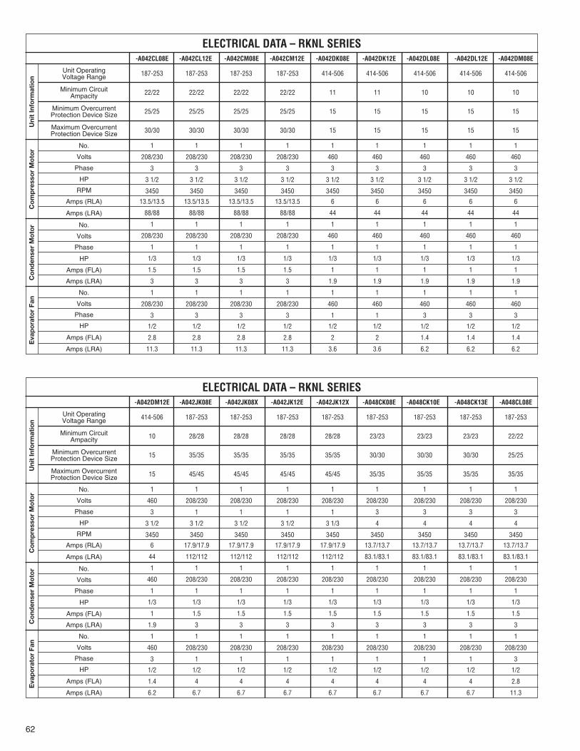
62
187-253 187-253 187-253 187-253 414-506 414-506 414-506 414-506 414-506
22/22 22/22 22/22 22/22 11 11 10 10 10
25/25 25/25 25/25 25/25 15 15 15 15 15
30/30 30/30 30/30 30/30 15 15 15 15 15
1 1 1 1 1 1 1 1 1
208/230 208/230 208/230 208/230 460 460 460 460 460
3 3 3 3 3 3 3 3 3
3 1/2 3 1/2 3 1/2 3 1/2 3 1/2 3 1/2 3 1/2 3 1/2 3 1/2
3450 3450 3450 3450 3450 3450 3450 3450 3450
13.5/13.5 13.5/13.5 13.5/13.5 13.5/13.5 6 6 6 6 6
88/88 88/88 88/88 88/88 44 44 44 44 44
1 1 1 1 1 1 1 1 1
208/230 208/230 208/230 208/230 460 460 460 460 460
1 1 1 1 1 1 1 1 1
1/3 1/3 1/3 1/3 1/3 1/3 1/3 1/3 1/3
1.5 1.5 1.5 1.5 1 1 1 1 1
3 3 3 3 1.9 1.9 1.9 1.9 1.9
1 1 1 1 1 1 1 1 1
208/230 208/230 208/230 208/230 460 460 460 460 460
3 3 3 3 1 1 3 3 3
1/2 1/2 1/2 1/2 1/2 1/2 1/2 1/2 1/2
2.8 2.8 2.8 2.8 2 2 1.4 1.4 1.4
11.3 11.3 11.3 11.3 3.6 3.6 6.2 6.2 6.2
Uni
t In
form
atio
nC
om
pre
sso
r M
oto
rC
ond
ense
r M
oto
rE
vap
ora
tor
Fan
ELECTRICAL DATA – RKNL SERIES-A042CL08E -A042CL12E -A042CM08E -A042CM12E -A042DK08E -A042DK12E -A042DL08E -A042DL12E -A042DM08E
Unit OperatingVoltage Range
Minimum CircuitAmpacity
Minimum OvercurrentProtection Device Size
Maximum OvercurrentProtection Device Size
No.
Volts
Phase
HP
RPM
Amps (RLA)
Amps (LRA)
No.
Volts
Phase
HP
Amps (FLA)
Amps (LRA)
No.
Volts
Phase
HP
Amps (FLA)
Amps (LRA)
414-506 187-253 187-253 187-253 187-253 187-253 187-253 187-253 187-253
10 28/28 28/28 28/28 28/28 23/23 23/23 23/23 22/22
15 35/35 35/35 35/35 35/35 30/30 30/30 30/30 25/25
15 45/45 45/45 45/45 45/45 35/35 35/35 35/35 35/35
1 1 1 1 1 1 1 1 1
460 208/230 208/230 208/230 208/230 208/230 208/230 208/230 208/230
3 1 1 1 1 3 3 3 3
3 1/2 3 1/2 3 1/2 3 1/2 3 1/3 4 4 4 4
3450 3450 3450 3450 3450 3450 3450 3450 3450
6 17.9/17.9 17.9/17.9 17.9/17.9 17.9/17.9 13.7/13.7 13.7/13.7 13.7/13.7 13.7/13.7
44 112/112 112/112 112/112 112/112 83.1/83.1 83.1/83.1 83.1/83.1 83.1/83.1
1 1 1 1 1 1 1 1 1
460 208/230 208/230 208/230 208/230 208/230 208/230 208/230 208/230
1 1 1 1 1 1 1 1 1
1/3 1/3 1/3 1/3 1/3 1/3 1/3 1/3 1/3
1 1.5 1.5 1.5 1.5 1.5 1.5 1.5 1.5
1.9 3 3 3 3 3 3 3 3
1 1 1 1 1 1 1 1 1
460 208/230 208/230 208/230 208/230 208/230 208/230 208/230 208/230
3 1 1 1 1 1 1 1 3
1/2 1/2 1/2 1/2 1/2 1/2 1/2 1/2 1/2
1.4 4 4 4 4 4 4 4 2.8
6.2 6.7 6.7 6.7 6.7 6.7 6.7 6.7 11.3
Uni
t In
form
atio
nC
om
pre
sso
r M
oto
rC
ond
ense
r M
oto
rE
vap
ora
tor
Fan
ELECTRICAL DATA – RKNL SERIES-A042DM12E -A042JK08E -A042JK08X -A042JK12E -A042JK12X -A048CK08E -A048CK10E -A048CK13E -A048CL08E
Unit OperatingVoltage Range
Minimum CircuitAmpacity
Minimum OvercurrentProtection Device Size
Maximum OvercurrentProtection Device Size
No.
Volts
Phase
HP
RPM
Amps (RLA)
Amps (LRA)
No.
Volts
Phase
HP
Amps (FLA)
Amps (LRA)
No.
Volts
Phase
HP
Amps (FLA)
Amps (LRA)

63
187-253 187-253 187-253 187-253 187-253 414-506 414-506 414-506 414-506
22/22 22/22 23/23 23/23 23/23 11 11 11 11
25/25 25/25 30/30 30/30 30/30 15 15 15 15
35/35 35/35 35/35 35/35 35/35 15 15 15 15
1 1 1 1 1 1 1 1 1
208/230 208/230 208/230 208/230 208/230 460 460 460 460
3 3 3 3 3 3 3 3 3
4 4 4 4 4 4 4 4 4
3450 3450 3450 3450 3450 3450 3450 3450 3450
13.7/13.7 13.7/13.7 13.7/13.7 13.7/13.7 13.7/13.7 6.2 6.2 6.2 6.2
83.1/83.1 83.1/83.1 83.1/83.1 83.1/83.1 83.1/83.1 41 41 41 41
1 1 1 1 1 1 1 1 1
208/230 208/230 208/230 208/230 208/230 460 460 460 460
1 1 1 1 1 1 1 1 1
1/3 1/3 1/3 1/3 1/3 1/3 1/3 1/3 1/3
1.5 1.5 1.5 1.5 1.5 1 1 1 1
3 3 3 3 3 1.9 1.9 1.9 1.9
1 1 1 1 1 1 1 1 1
208/230 208/230 208/230 208/230 208/230 460 460 460 460
3 3 3 3 3 1 1 1 3
1/2 1/2 3/4 3/4 3/4 1/2 1/2 1/2 1/2
2.8 2.8 3.4 3.4 3.4 2 2 2 1.4
11.3 11.3 16.8 16.8 16.8 3.6 3.6 3.6 6.2
Uni
t In
form
atio
nC
om
pre
sso
r M
oto
rC
ond
ense
r M
oto
rE
vap
ora
tor
Fan
ELECTRICAL DATA – RKNL SERIES-A048CL10E -A048CL13E -A048CM08E -A048CM10E -A048CM13E -A048DK08E -A048DK10E -A048DK13E -A048DL08E
Unit OperatingVoltage Range
Minimum CircuitAmpacity
Minimum OvercurrentProtection Device Size
Maximum OvercurrentProtection Device Size
No.
Volts
Phase
HP
RPM
Amps (RLA)
Amps (LRA)
No.
Volts
Phase
HP
Amps (FLA)
Amps (LRA)
No.
Volts
Phase
HP
Amps (FLA)
Amps (LRA)
414-506 414-506 414-506 414-506 414-506 187-253 187-253 187-253 187-253
11 11 11 11 11 33/33 33/33 33/33 33/33
15 15 15 15 15 40/40 40/40 40/40 40/40
15 15 15 15 15 50/50 50/50 50/50 50/50
1 1 1 1 1 1 1 1 1
460 460 460 460 460 208/230 208/230 208/230 208/230
3 3 3 3 3 1 1 1 1
4 4 4 4 4 4 4 4 4
3450 3450 3450 3450 3450 3450 3450 3450 3450
6.2 6.2 6.2 6.2 6.2 21.8/21.8 21.8/21.8 21.8/21.8 21.8/21.8
41 41 41 41 41 117/117 117/117 117/117 117/117
1 1 1 1 1 1 1 1 1
460 460 460 460 460 208/230 208/230 208/230 208/230
1 1 1 1 1 1 1 1 1
1/3 1/3 1/3 1/3 1/3 1/3 1/3 1/3 1/3
1 1 1 1 1 1.5 1.5 1.5 1.5
1.9 1.9 1.9 1.9 1.9 3 3 3 3
1 1 1 1 1 1 1 1 1
460 460 460 460 460 208/230 208/230 208/230 208/230
3 3 3 3 3 1 1 1 1
1/2 1/2 3/4 3/4 3/4 1/2 1/2 1/2 1/2
1.4 1.4 1.6 1.6 1.6 4 4 4 4
6.2 6.2 8.4 8.4 8.4 6.7 6.7 6.7 6.7
Uni
t In
form
atio
nC
om
pre
sso
r M
oto
rC
ond
ense
r M
oto
rE
vap
ora
tor
Fan
ELECTRICAL DATA – RKNL SERIES-A048DL10E -A048DL13E -A048DM08E -A048DM10E -A048DM13E -A048JK08E -A048JK08X -A048JK10E -A048JK10X
Unit OperatingVoltage Range
Minimum CircuitAmpacity
Minimum OvercurrentProtection Device Size
Maximum OvercurrentProtection Device Size
No.
Volts
Phase
HP
RPM
Amps (RLA)
Amps (LRA)
No.
Volts
Phase
HP
Amps (FLA)
Amps (LRA)
No.
Volts
Phase
HP
Amps (FLA)
Amps (LRA)

64
187-253 187-253 187-253 187-253 187-253 187-253 187-253 187-253 414-506
33/33 33/33 30/30 30/30 26/26 26/26 26/26 26/26 13
40/40 40/40 35/35 35/35 30/30 30/30 30/30 30/30 15
50/50 50/50 40/40 40/40 40/40 40/40 40/40 40/40 20
1 1 1 1 1 1 1 1 1
208/230 208/230 208/230 208/230 208/230 208/230 208/230 208/230 460
1 1 3 3 3 3 3 3 3
4 4 5 5 5 5 5 5 5
3450 3450 3450 3450 3450 3450 3450 3450 3450
21.8/21.8 21.8/21.8 15.6/15.6 15.6/15.6 15.6/15.6 15.6/15.6 15.6/15.6 15.6/15.6 7.8
117/117 117/117 110/110 110/110 110/110 110/110 110/110 110/110 52
1 1 1 1 1 1 1 1 1
208/230 208/230 208/230 208/230 208/230 208/230 208/230 208/230 460
1 1 1 1 1 1 1 1 1
1/3 1/3 1/3 1/3 1/3 1/3 1/3 1/3 1/3
1.5 1.5 2.2 2.2 2.2 2.2 2.2 2.2 1
3 3 4.9 4.9 4.9 4.9 4.9 4.9 1.9
1 1 1 1 1 1 1 1 1
208/230 208/230 208/230 208/230 208/230 208/230 208/230 208/230 460
1 1 1 1 3 3 3 3 3
1/2 1/2 1 1 3/4 3/4 1 1 3/4
4 4 7.6 7.6 3.4 3.4 3.8 3.8 1.6
6.7 6.7 0 0 16.8 16.8 24 24 8.4
Uni
t In
form
atio
nC
om
pre
sso
r M
oto
rC
ond
ense
r M
oto
rE
vap
ora
tor
Fan
ELECTRICAL DATA – RKNL SERIES-A048JK13E -A048JK13X -A060CK10E -A060CK13E -A060CL10E -A060CL13E -A060CM10E -A060CM13E -A060DL10E
Unit OperatingVoltage Range
Minimum CircuitAmpacity
Minimum OvercurrentProtection Device Size
Maximum OvercurrentProtection Device Size
No.
Volts
Phase
HP
RPM
Amps (RLA)
Amps (LRA)
No.
Volts
Phase
HP
Amps (FLA)
Amps (LRA)
No.
Volts
Phase
HP
Amps (FLA)
Amps (LRA)
414-506 414-506 414-506 187-253 187-253 187-253 187-253
13 13 13 43/43 43/43 43/43 43/43
15 15 15 50/50 50/50 50/50 50/50
20 20 20 60/60 60/60 60/60 60/60
1 1 1 1 1 1 1
460 460 460 208/230 208/230 208/230 208/230
3 3 3 1 1 1 1
5 5 5 5 5 5 5
3450 3450 3450 3450 3450 3450 3450
7.8 7.8 7.8 26.3/26.3 26.3/26.3 26.3/26.3 26.3/26.3
52 52 52 134/134 134/134 134/134 134/134
1 1 1 1 1 1 1
460 460 460 208/230 208/230 208/230 208/230
1 1 1 1 1 1 1
1/3 1/3 1/3 1/3 1/3 1/3 1/3
1 1 1 2.2 2.2 2.2 2.2
1.9 1.9 1.9 4.9 4.9 4.9 4.9
1 1 1 1 1 1 1
460 460 460 208/230 208/230 208/230 208/230
3 3 3 1 1 1 1
3/4 1 1 1 1 1 1
1.6 1.9 1.9 7.6 7.6 7.6 7.6
8.4 12 12 0 0 0 0
Uni
t In
form
atio
nC
om
pre
sso
r M
oto
rC
ond
ense
r M
oto
rE
vap
ora
tor
Fan
ELECTRICAL DATA – RKNL SERIES-A060DL13E -A060DM10E -A060DM13E -A060JK10E -A060JK10X -A060JK13E -A060JK13X
Unit OperatingVoltage Range
Minimum CircuitAmpacity
Minimum OvercurrentProtection Device Size
Maximum OvercurrentProtection Device Size
No.
Volts
Phase
HP
RPM
Amps (RLA)
Amps (LRA)
No.
Volts
Phase
HP
Amps (FLA)
Amps (LRA)
No.
Volts
Phase
HP
Amps (FLA)
Amps (LRA)
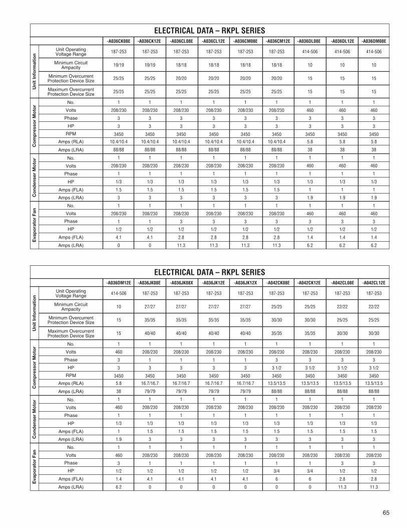
65
187-253 187-253 187-253 187-253 187-253 187-253 414-506 414-506 414-506
19/19 19/19 18/18 18/18 18/18 18/18 10 10 10
25/25 25/25 20/20 20/20 20/20 20/20 15 15 15
25/25 25/25 25/25 25/25 25/25 25/25 15 15 15
1 1 1 1 1 1 1 1 1
208/230 208/230 208/230 208/230 208/230 208/230 460 460 460
3 3 3 3 3 3 3 3 3
3 3 3 3 3 3 3 3 3
3450 3450 3450 3450 3450 3450 3450 3450 3450
10.4/10.4 10.4/10.4 10.4/10.4 10.4/10.4 10.4/10.4 10.4/10.4 5.8 5.8 5.8
88/88 88/88 88/88 88/88 88/88 88/88 38 38 38
1 1 1 1 1 1 1 1 1
208/230 208/230 208/230 208/230 208/230 208/230 460 460 460
1 1 1 1 1 1 1 1 1
1/3 1/3 1/3 1/3 1/3 1/3 1/3 1/3 1/3
1.5 1.5 1.5 1.5 1.5 1.5 1 1 1
3 3 3 3 3 3 1.9 1.9 1.9
1 1 1 1 1 1 1 1 1
208/230 208/230 208/230 208/230 208/230 208/230 460 460 460
1 1 3 3 3 3 3 3 3
1/2 1/2 1/2 1/2 1/2 1/2 1/2 1/2 1/2
4.1 4.1 2.8 2.8 2.8 2.8 1.4 1.4 1.4
0 0 11.3 11.3 11.3 11.3 6.2 6.2 6.2
Uni
t In
form
atio
nC
om
pre
sso
r M
oto
rC
ond
ense
r M
oto
rE
vap
ora
tor
Fan
ELECTRICAL DATA – RKPL SERIES-A036CK08E -A036CK12E -A036CL08E -A036CL12E -A036CM08E -A036CM12E -A036DL08E -A036DL12E -A036DM08E
Unit OperatingVoltage Range
Minimum CircuitAmpacity
Minimum OvercurrentProtection Device Size
Maximum OvercurrentProtection Device Size
No.
Volts
Phase
HP
RPM
Amps (RLA)
Amps (LRA)
No.
Volts
Phase
HP
Amps (FLA)
Amps (LRA)
No.
Volts
Phase
HP
Amps (FLA)
Amps (LRA)
414-506 187-253 187-253 187-253 187-253 187-253 187-253 187-253 187-253
10 27/27 27/27 27/27 27/27 25/25 25/25 22/22 22/22
15 35/35 35/35 35/35 35/35 30/30 30/30 25/25 25/25
15 40/40 40/40 40/40 40/40 35/35 35/35 30/30 30/30
1 1 1 1 1 1 1 1 1
460 208/230 208/230 208/230 208/230 208/230 208/230 208/230 208/230
3 1 1 1 1 3 3 3 3
3 3 3 3 3 3 1/2 3 1/2 3 1/2 3 1/2
3450 3450 3450 3450 3450 3450 3450 3450 3450
5.8 16.7/16.7 16.7/16.7 16.7/16.7 16.7/16.7 13.5/13.5 13.5/13.5 13.5/13.5 13.5/13.5
38 79/79 79/79 79/79 79/79 88/88 88/88 88/88 88/88
1 1 1 1 1 1 1 1 1
460 208/230 208/230 208/230 208/230 208/230 208/230 208/230 208/230
1 1 1 1 1 1 1 1 1
1/3 1/3 1/3 1/3 1/3 1/3 1/3 1/3 1/3
1 1.5 1.5 1.5 1.5 1.5 1.5 1.5 1.5
1.9 3 3 3 3 3 3 3 3
1 1 1 1 1 1 1 1 1
460 208/230 208/230 208/230 208/230 208/230 208/230 208/230 208/230
3 1 1 1 1 1 1 3 3
1/2 1/2 1/2 1/2 1/2 3/4 3/4 1/2 1/2
1.4 4.1 4.1 4.1 4.1 6 6 2.8 2.8
6.2 0 0 0 0 0 0 11.3 11.3
Uni
t In
form
atio
nC
om
pre
sso
r M
oto
rC
ond
ense
r M
oto
rE
vap
ora
tor
Fan
ELECTRICAL DATA – RKPL SERIES-A036DM12E -A036JK08E -A036JK08X -A036JK12E -A036JK12X -A042CK08E -A042CK12E -A042CL08E -A042CL12E
Unit OperatingVoltage Range
Minimum CircuitAmpacity
Minimum OvercurrentProtection Device Size
Maximum OvercurrentProtection Device Size
No.
Volts
Phase
HP
RPM
Amps (RLA)
Amps (LRA)
No.
Volts
Phase
HP
Amps (FLA)
Amps (LRA)
No.
Volts
Phase
HP
Amps (FLA)
Amps (LRA)
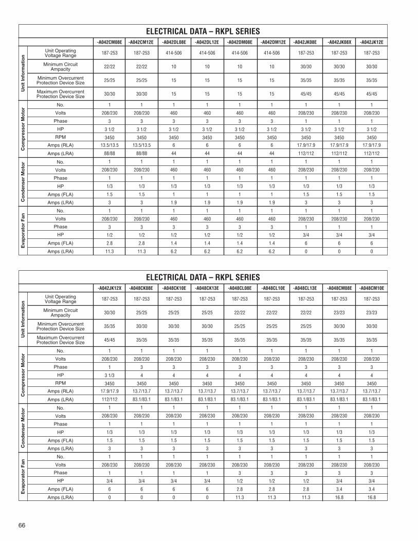
66
187-253 187-253 414-506 414-506 414-506 414-506 187-253 187-253 187-253
22/22 22/22 10 10 10 10 30/30 30/30 30/30
25/25 25/25 15 15 15 15 35/35 35/35 35/35
30/30 30/30 15 15 15 15 45/45 45/45 45/45
1 1 1 1 1 1 1 1 1
208/230 208/230 460 460 460 460 208/230 208/230 208/230
3 3 3 3 3 3 1 1 1
3 1/2 3 1/2 3 1/2 3 1/2 3 1/2 3 1/2 3 1/2 3 1/2 3 1/2
3450 3450 3450 3450 3450 3450 3450 3450 3450
13.5/13.5 13.5/13.5 6 6 6 6 17.9/17.9 17.9/17.9 17.9/17.9
88/88 88/88 44 44 44 44 112/112 112/112 112/112
1 1 1 1 1 1 1 1 1
208/230 208/230 460 460 460 460 208/230 208/230 208/230
1 1 1 1 1 1 1 1 1
1/3 1/3 1/3 1/3 1/3 1/3 1/3 1/3 1/3
1.5 1.5 1 1 1 1 1.5 1.5 1.5
3 3 1.9 1.9 1.9 1.9 3 3 3
1 1 1 1 1 1 1 1 1
208/230 208/230 460 460 460 460 208/230 208/230 208/230
3 3 3 3 3 3 1 1 1
1/2 1/2 1/2 1/2 1/2 1/2 3/4 3/4 3/4
2.8 2.8 1.4 1.4 1.4 1.4 6 6 6
11.3 11.3 6.2 6.2 6.2 6.2 0 0 0
Uni
t In
form
atio
nC
om
pre
sso
r M
oto
rC
ond
ense
r M
oto
rE
vap
ora
tor
Fan
ELECTRICAL DATA – RKPL SERIES-A042CM08E -A042CM12E -A042DL08E -A042DL12E -A042DM08E -A042DM12E -A042JK08E -A042JK08X -A042JK12E
Unit OperatingVoltage Range
Minimum CircuitAmpacity
Minimum OvercurrentProtection Device Size
Maximum OvercurrentProtection Device Size
No.
Volts
Phase
HP
RPM
Amps (RLA)
Amps (LRA)
No.
Volts
Phase
HP
Amps (FLA)
Amps (LRA)
No.
Volts
Phase
HP
Amps (FLA)
Amps (LRA)
187-253 187-253 187-253 187-253 187-253 187-253 187-253 187-253 187-253
30/30 25/25 25/25 25/25 22/22 22/22 22/22 23/23 23/23
35/35 30/30 30/30 30/30 25/25 25/25 25/25 30/30 30/30
45/45 35/35 35/35 35/35 35/35 35/35 35/35 35/35 35/35
1 1 1 1 1 1 1 1 1
208/230 208/230 208/230 208/230 208/230 208/230 208/230 208/230 208/230
1 3 3 3 3 3 3 3 3
3 1/3 4 4 4 4 4 4 4 4
3450 3450 3450 3450 3450 3450 3450 3450 3450
17.9/17.9 13.7/13.7 13.7/13.7 13.7/13.7 13.7/13.7 13.7/13.7 13.7/13.7 13.7/13.7 13.7/13.7
112/112 83.1/83.1 83.1/83.1 83.1/83.1 83.1/83.1 83.1/83.1 83.1/83.1 83.1/83.1 83.1/83.1
1 1 1 1 1 1 1 1 1
208/230 208/230 208/230 208/230 208/230 208/230 208/230 208/230 208/230
1 1 1 1 1 1 1 1 1
1/3 1/3 1/3 1/3 1/3 1/3 1/3 1/3 1/3
1.5 1.5 1.5 1.5 1.5 1.5 1.5 1.5 1.5
3 3 3 3 3 3 3 3 3
1 1 1 1 1 1 1 1 1
208/230 208/230 208/230 208/230 208/230 208/230 208/230 208/230 208/230
1 1 1 1 3 3 3 3 3
3/4 3/4 3/4 3/4 1/2 1/2 1/2 3/4 3/4
6 6 6 6 2.8 2.8 2.8 3.4 3.4
0 0 0 0 11.3 11.3 11.3 16.8 16.8
Uni
t In
form
atio
nC
om
pre
sso
r M
oto
rC
ond
ense
r M
oto
rE
vap
ora
tor
Fan
ELECTRICAL DATA – RKPL SERIES-A042JK12X -A048CK08E -A048CK10E -A048CK13E -A048CL08E -A048CL10E -A048CL13E -A048CM08E -A048CM10E
Unit OperatingVoltage Range
Minimum CircuitAmpacity
Minimum OvercurrentProtection Device Size
Maximum OvercurrentProtection Device Size
No.
Volts
Phase
HP
RPM
Amps (RLA)
Amps (LRA)
No.
Volts
Phase
HP
Amps (FLA)
Amps (LRA)
No.
Volts
Phase
HP
Amps (FLA)
Amps (LRA)

67
187-253 414-506 414-506 414-506 414-506 414-506 414-506 187-253 187-253
23/23 11 11 11 11 11 11 35/35 35/35
30/30 15 15 15 15 15 15 45/45 45/45
35/35 15 15 15 15 15 15 50/50 50/50
1 1 1 1 1 1 1 1 1
208/230 460 460 460 460 460 460 208/230 208/230
3 3 3 3 3 3 3 1 1
4 4 4 4 4 4 4 4 4
3450 3450 3450 3450 3450 3450 3450 3450 3450
13.7/13.7 6.2 6.2 6.2 6.2 6.2 6.2 21.8/21.8 21.8/21.8
83.1/83.1 41 41 41 41 41 41 117/117 117/117
1 1 1 1 1 1 1 1 1
208/230 460 460 460 460 460 460 208/230 208/230
1 1 1 1 1 1 1 1 1
1/3 1/3 1/3 1/3 1/3 1/3 1/3 1/3 1/3
1.5 1 1 1 1 1 1 1.5 1.5
3 1.9 1.9 1.9 1.9 1.9 1.9 3 3
1 1 1 1 1 1 1 1 1
208/230 460 460 460 460 460 460 208/230 208/230
3 3 3 3 3 3 3 1 1
3/4 1/2 1/2 1/2 3/4 3/4 3/4 3/4 3/4
3.4 1.4 1.4 1.4 1.6 1.6 1.6 6 6
16.8 6.2 6.2 6.2 8.4 8.4 8.4 0 0
Uni
t In
form
atio
nC
om
pre
sso
r M
oto
rC
ond
ense
r M
oto
rE
vap
ora
tor
Fan
ELECTRICAL DATA – RKPL SERIES-A048CM13E -A048DL08E -A048DL10E -A048DL13E -A048DM08E -A048DM10E -A048DM13E -A048JK08E -A048JK08X
Unit OperatingVoltage Range
Minimum CircuitAmpacity
Minimum OvercurrentProtection Device Size
Maximum OvercurrentProtection Device Size
No.
Volts
Phase
HP
RPM
Amps (RLA)
Amps (LRA)
No.
Volts
Phase
HP
Amps (FLA)
Amps (LRA)
No.
Volts
Phase
HP
Amps (FLA)
Amps (LRA)
187-253 187-253 187-253 187-253 187-253 187-253 187-253 187-253 187-253
35/35 35/35 35/35 35/35 30/30 30/30 26/26 26/26 26/26
45/45 45/45 45/45 45/45 35/35 35/35 30/30 30/30 35/35
50/50 50/50 50/50 50/50 45/45 45/45 40/40 40/40 40/40
1 1 1 1 1 1 1 1 1
208/230 208/230 208/230 208/230 208/230 208/230 208/230 208/230 208/230
1 1 1 1 3 3 3 3 3
4 4 4 4 5 5 5 5 5
3450 3450 3450 3450 3450 3450 3450 3450 3450
21.8/21.8 21.8/21.8 21.8/21.8 21.8/21.8 16/16 16/16 16/16 16/16 16/16
117/117 117/117 117/117 117/117 110/110 110/110 110/110 110/110 110/110
1 1 1 1 1 1 1 1 1
208/230 208/230 208/230 208/230 208/230 208/230 208/230 208/230 208/230
1 1 1 1 1 1 1 1 1
1/3 1/3 1/3 1/3 1/3 1/3 1/3 1/3 1/3
1.5 1.5 1.5 1.5 2.2 2.2 2.2 2.2 2.2
3 3 3 3 4.9 4.9 4.9 4.9 4.9
1 1 1 1 1 1 1 1 1
208/230 208/230 208/230 208/230 208/230 208/230 208/230 208/230 208/230
1 1 1 1 1 1 3 3 3
3/4 3/4 3/4 3/4 1 1 3/4 3/4 1
6 6 6 6 7.6 7.6 3.4 3.4 3.8
0 0 0 0 0 0 16.8 16.8 24
Uni
t In
form
atio
nC
om
pre
sso
r M
oto
rC
ond
ense
r M
oto
rE
vap
ora
tor
Fan
ELECTRICAL DATA – RKPL SERIES-A048JK10E -A048JK10X -A048JK13E -A048JK13X -A060CK10E -A060CK13E -A060CL10E -A060CL13E -A060CM10E
Unit OperatingVoltage Range
Minimum CircuitAmpacity
Minimum OvercurrentProtection Device Size
Maximum OvercurrentProtection Device Size
No.
Volts
Phase
HP
RPM
Amps (RLA)
Amps (LRA)
No.
Volts
Phase
HP
Amps (FLA)
Amps (LRA)
No.
Volts
Phase
HP
Amps (FLA)
Amps (LRA)

68
187-253 414-506 414-506 414-506 414-506 187-253 187-253 187-253 187-253
26/26 13 13 13 13 43/43 43/43 43/43 43/43
35/35 15 15 15 15 50/50 50/50 50/50 50/50
40/40 20 20 20 20 60/60 60/60 60/60 60/60
1 1 1 1 1 1 1 1 1
208/230 460 460 460 460 208/230 208/230 208/230 208/230
3 3 3 3 3 1 1 1 1
5 5 5 5 5 5 5 5 5
3450 3450 3450 3450 3450 3450 3450 3450 3450
16/16 7.8 7.8 7.8 7.8 26.4/26.4 26.4/26.4 26.4/26.4 26.4/26.4
110/110 52 52 52 52 134/134 134/134 134/134 134/134
1 1 1 1 1 1 1 1 1
208/230 460 460 460 460 208/230 208/230 208/230 208/230
1 1 1 1 1 1 1 1 1
1/3 1/3 1/3 1/3 1/3 1/3 1/3 1/3 1/3
2.2 1 1 1 1 2.2 2.2 2.2 2.2
4.9 1.9 1.9 1.9 1.9 4.9 4.9 4.9 4.9
1 1 1 1 1 1 1 1 1
208/230 460 460 460 460 208/230 208/230 208/230 208/230
3 3 3 3 3 1 1 1 1
1 3/4 3/4 1 1 1 1 1 1
3.8 1.6 1.6 1.9 1.9 7.6 7.6 7.6 7.6
24 8.4 8.4 12 12 0 0 0 0
Uni
t In
form
atio
nC
om
pre
sso
r M
oto
rC
ond
ense
r M
oto
rE
vap
ora
tor
Fan
ELECTRICAL DATA – RKPL SERIES-A060CM13E -A060DL10E -A060DL13E -A060DM10E -A060DM13E -A060JK10E -A060JK10X -A060JK13E -A060JK13X
Unit OperatingVoltage Range
Minimum CircuitAmpacity
Minimum OvercurrentProtection Device Size
Maximum OvercurrentProtection Device Size
No.
Volts
Phase
HP
RPM
Amps (RLA)
Amps (LRA)
No.
Volts
Phase
HP
Amps (FLA)
Amps (LRA)
No.
Volts
Phase
HP
Amps (FLA)
Amps (LRA)

69
0.1
0.2
0.3
0.4
0.5
0.6
0.7
0.8
CF
M12
1011
9311
7511
5511
2510
7510
1592
5W
atts
450
400
395
385
380
375
370
360
CF
M15
1515
0014
7514
5014
0513
5012
7511
80W
atts
525
515
510
505
490
475
460
445
CF
M16
8016
5016
2515
8015
3014
6013
9012
80W
atts
650
640
630
610
580
560
545
515
CF
M12
1011
9311
7511
5511
2510
7510
1592
5W
atts
450
400
395
385
380
375
370
360
CF
M15
1515
0014
7514
5014
0513
5012
7511
80W
atts
525
515
510
505
490
475
460
445
CF
M16
8016
5016
2515
8015
3014
6013
9012
80W
atts
650
640
630
610
580
560
545
515
CF
M12
1011
9311
7511
5511
2510
7510
1592
5W
atts
450
400
395
385
380
375
370
360
CF
M15
1515
0014
7514
5014
0513
5012
7511
80W
atts
525
515
510
505
490
475
460
445
CF
M16
8016
5016
2515
8015
3014
6013
9012
80W
atts
650
640
630
610
580
560
545
515
CF
M15
7515
3614
9614
5714
1713
7713
3812
98W
atts
297
314
330
347
364
381
397
414
CF
M19
8519
5419
1918
7618
2417
5916
7915
81W
atts
535
553
574
593
606
609
599
572
CF
M24
3123
7223
0622
2821
3820
3219
0717
62W
atts
970
981
964
926
872
806
736
665
DIR
EC
T-D
RIV
E B
LOW
ER
208
AIR
FLO
W P
ER
FOR
MA
NC
E
CFM
Air
Del
iver
y/R
PM
/Wat
ts-2
08 V
OLT
S
Ext
ern
al S
tati
c P
ress
ure
-In
ches
W.C
.U
nit M
odel
RK
NL-
A03
6
RK
NL-
A04
2
Coo
l
Low
Med
Hea
t
Low
Med
Mot
or S
peed
Fro
m F
acto
ryH
eatin
gIn
put
BT
U/h
r[k
W]
80,0
00[2
3.45
]
120,
000
[35.
17]
Man
ufac
ture
rR
ecom
men
ded
Air-
Flo
w R
ange
(Min
/ M
ax)
CF
M
1050
/ 13
50
Blo
wer
Siz
e/M
otor
HP
#of
Spe
eds
10x1
01/
23
Spe
ed(P
SC
)
Mot
orS
peed
Low
Med
Hig
h
Low
Med
80,0
00[2
3.45
]
120,
000
[35.
17]
1225
/ 15
75
10x1
01/
23
Spe
ed(P
SC
)
Low
Med
Hig
h
RK
NL-
A04
8M
ed
Low
Med
Hig
h
80,0
00[2
3.45
]
100,
000
[29.
31]
135,
000
[39.
56]
1400
/ 18
00
10x1
01/
23
Spe
ed(P
SC
)
Low
Med
Hig
h
RK
NL-
A06
0M
ed
Low
Hig
h
100,
000
[29.
31]
135,
000
[39.
56]
1750
/ 22
50
10x1
01
3 S
peed
(X-1
3)
Low
Med
Hig
h
INDOOR AIRFLOW PERFORMANCE FOR 3-5 TON PACKAGE GAS ELECTRIC UNITS – RKNLDIRECT DRIVE

70
0.1
0.2
0.3
0.4
0.5
0.6
0.7
0.8
CF
M14
0013
7513
6013
3513
0512
5512
1011
00W
atts
470
460
455
450
440
435
425
410
CF
M16
8516
2015
8015
5015
0014
3013
5012
30W
atts
635
600
580
570
550
535
505
475
CF
M18
7018
3017
9017
3016
6015
8015
0013
75W
atts
780
760
740
700
660
635
600
555
CF
M14
0013
7513
6013
3513
0512
5512
1011
00W
atts
470
460
455
450
440
435
425
410
CF
M16
8516
2015
8015
5015
0014
3013
5012
30W
atts
635
600
580
570
550
535
505
475
CF
M18
7018
3017
9017
3016
6015
8015
0013
75W
atts
780
760
740
700
660
635
600
555
CF
M14
0013
7513
6013
3513
0512
5512
1011
00W
atts
470
460
455
450
440
435
425
410
CF
M16
8516
2015
8015
5015
0014
3013
5012
30W
atts
635
600
580
570
550
535
505
475
CF
M18
7018
3017
9017
3016
6015
8015
0013
75W
atts
780
760
740
700
660
635
600
555
CF
M15
7515
3614
9614
5714
1713
7713
3812
98W
atts
297
314
330
347
364
381
397
414
CF
M19
8519
5419
1918
7618
2417
5916
7915
81W
atts
535
553
574
593
606
609
599
572
CF
M24
3123
7223
0622
2821
3820
3219
0717
62W
atts
970
981
964
926
872
806
736
665
DIR
EC
T-D
RIV
E 2
30 A
IRFL
OW
PE
RFO
RM
AN
CE
CFM
Air
Del
iver
y/R
PM
/Wat
ts-2
30 V
OLT
S
Ext
ern
al S
tati
c P
ress
ure
-In
ches
W.C
.U
nit M
odel
RK
NL-
A03
6
RK
NL-
A04
2
Coo
l
Low
Med
Hea
t
Low
Med
Mot
or S
peed
Fro
m F
acto
ryH
eatin
gIn
put
BT
U/h
r[k
W]
80,0
00[2
3.45
]
120,
000
[35.
17]
Man
ufac
ture
rR
ecom
men
ded
Air-
Flo
w R
ange
(Min
/ M
ax)
CF
M
1050
/ 13
50
Blo
wer
Siz
e/M
otor
HP
#of
Spe
eds
10x1
01/
23
Spe
ed(P
SC
)
Mot
orS
peed
Low
Med
Hig
h
Low
Med
80,0
00[2
3.45
]
120,
000
[35.
17]
1225
/ 15
75
10x1
01/
23
Spe
ed(P
SC
)
Low
Med
Hig
h
RK
NL-
A04
8M
ed
Low
Med
Hig
h
80,0
00[2
3.45
]
100,
000
[29.
31]
135,
000
[39.
56]
1400
/ 18
00
10x1
01/
23
Spe
ed(P
SC
)
Low
Med
Hig
h
RK
NL-
A06
0M
ed
Low
Hig
h
100,
000
[29.
31]
135,
000
[39.
56]
1750
/ 22
50
10x1
01
3 S
peed
(X-1
3)
Low
Med
Hig
h
INDOOR AIRFLOW PERFORMANCE FOR 3-5 TON PACKAGE GAS ELECTRIC UNITS – RKNLDIRECT DRIVE

71
0.1
0.2
0.3
0.4
0.5
0.6
0.7
0.8
CF
M14
0013
7513
6013
3513
0512
5512
1011
00
Wat
ts47
046
045
545
044
043
542
541
0
CF
M16
8516
2015
8015
5015
0014
3013
5012
30
Wat
ts63
560
058
057
055
053
550
547
5
CF
M18
7018
3017
9017
3016
6015
8015
0013
75
Wat
ts78
076
074
070
066
063
560
055
5
CF
M14
0013
7513
6013
3513
0512
5512
1011
00
Wat
ts47
046
045
545
044
043
542
541
0
CF
M16
8516
2015
8015
5015
0014
3013
5012
30
Wat
ts63
560
058
057
055
053
550
547
5
CF
M18
7018
3017
9017
3016
6015
8015
0013
75
Wat
ts78
076
074
070
066
063
560
055
5
CF
M14
0013
7513
6013
3513
0512
5512
1011
00
Wat
ts47
046
045
545
044
043
542
541
0
CF
M16
8516
2015
8015
5015
0014
3013
5012
30
Wat
ts63
560
058
057
055
053
550
547
5
CF
M18
7018
3017
9017
3016
6015
8015
0013
75
Wat
ts78
076
074
070
066
063
560
055
5
CFM
Air
Del
iver
y/R
PM
/Wat
ts-4
60 V
OLT
S
Ext
ern
al S
tati
c P
ress
ure
-In
ches
W.C
.
DIR
EC
T-D
RIV
E 4
60 A
IRFL
OW
PE
RFO
RM
AN
CE
Uni
t Mod
el
RK
NL-
A03
6
RK
NL-
A04
2
RK
NL-
A04
8
Coo
l
Low
Med
Hig
h
Hea
t
Low
Mot
or S
peed
Fro
m F
acto
ryH
eatin
gIn
put
BT
U/h
r[k
W]
80,0
00[2
3.45
]12
0,00
0[3
5.17
]
Man
ufac
ture
rR
ecom
men
ded
Air-
Flo
w R
ange
(Min
/ M
ax)
CF
M
1050
/ 13
50
Blo
wer
Siz
e/M
otor
HP
#of
Spe
eds
10x1
01/
23
Spe
ed(P
SC
)
Mot
orS
peed
Low
Med
Hig
h
Med
Hig
h
80,0
00[2
3.45
]12
0,00
0[3
5.17
]
80,0
00[2
3.45
]13
5,00
0[3
9.56
]
1225
/ 15
75
1400
/ 18
00
10x1
01/
23
Spe
ed(P
SC
)
Low
Med
Hig
h
10x1
01/
23
Spe
ed(P
SC
)
Low
Med
Hig
h
INDOOR AIRFLOW PERFORMANCE FOR 3-5 TON PACKAGE GAS ELECTRIC UNITS – RKNLDIRECT DRIVE
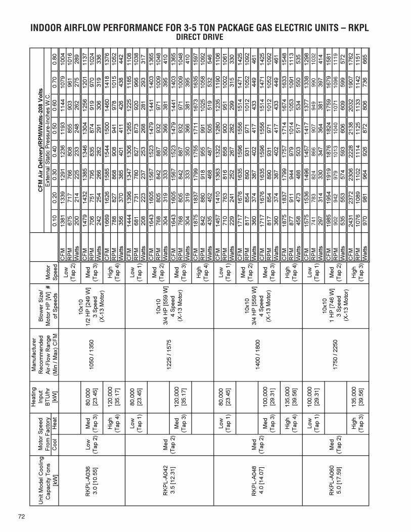
72
INDOOR AIRFLOW PERFORMANCE FOR 3-5 TON PACKAGE GAS ELECTRIC UNITS – RKPLDIRECT DRIVE
Hea
ting
Inpu
tB
TU/h
rC
ool
Hea
t[k
W]
0.10
0.20
0.30
0.40
0.50
0.60
0.70
0.80
CFM
1381
1339
1291
1236
1193
1144
1079
1004
RP
M67
571
776
680
885
590
396
110
16W
atts
200
214
225
233
248
262
275
289
CFM
1479
1432
1385
1346
1304
1256
1201
1137
RP
M70
675
179
583
587
491
997
010
24W
atts
242
254
266
282
291
306
319
336
CFM
1669
1626
1585
1544
1500
1460
1418
1376
RP
M78
882
786
890
894
197
810
1510
52W
atts
356
370
385
401
411
426
438
442
CFM
1444
1396
1347
1306
1265
1225
1185
1108
RP
M68
173
178
082
787
392
096
610
38W
atts
208
223
237
253
268
281
293
317
CFM
1643
1605
1567
1523
1479
1441
1403
1365
RP
M76
880
584
288
793
297
110
0910
48W
atts
304
319
333
350
366
381
395
410
CFM
1643
1605
1567
1523
1479
1441
1403
1365
RP
M76
880
584
288
793
297
110
0910
48W
atts
304
319
333
350
366
381
395
410
CFM
1875
1837
1799
1755
1711
1673
1635
1597
RP
M84
288
091
895
599
110
2510
5810
92W
atts
435
452
468
487
505
519
532
546
CFM
1457
1410
1363
1322
1280
1235
1190
1106
RP
M71
076
381
685
890
095
110
0210
61W
atts
229
241
252
267
282
299
315
330
CFM
1717
1676
1635
1596
1556
1514
1471
1425
RP
M81
785
489
093
197
110
1210
5210
92W
atts
360
374
387
402
417
433
449
461
CFM
1717
1676
1635
1596
1556
1514
1471
1425
RP
M81
785
489
093
197
110
1210
5210
92W
atts
360
374
387
402
417
433
449
461
CFM
1875
1837
1799
1757
1714
1674
1633
1548
RP
M87
791
194
497
910
1410
5310
9111
13W
atts
458
473
488
503
517
534
550
535
CFM
1575
1536
1496
1457
1417
1377
1338
1298
RP
MW
atts
297
314
330
347
364
381
397
414
CFM
1985
1954
1919
1876
1824
1759
1679
1581
RP
MW
atts
535
553
574
593
606
609
599
572
CFM
2431
2372
2306
2228
2138
2032
1907
1762
RP
M10
7610
8911
0211
1411
2511
3311
4211
51W
atts
970
981
964
926
872
806
736
665
Med
(T
ap 3
)M
ed
(Tap
3)
120,
000
[35.
17]
10x1
0
4 S
peed
Low
(T
ap 1
)
Med
(T
ap 2
)
Hig
h (T
ap 4
)
10x1
0
3 S
peed
Low
(T
ap 2
)
100,
000
[29.
31]
10x1
0
3 S
peed
Low
(T
ap 1
)
Med
(T
ap 2
)
Hig
h (T
ap 3
)
RK
PL-
A06
0
5.
0 [1
7.59
]M
ed
(Tap
2)
1750
/ 22
50
Low
(T
ap 1
)
Hig
h (T
ap 3
)
100,
000
[29.
31]
135,
000
[39.
56]
10x1
0
4 S
peed
Low
(T
ap 1
)
Med
(T
ap 2
)
Hig
h (T
ap 4
)
Med
(T
ap 3
)
(Tap
2)
1400
/ 18
00
Low
(T
ap 1
)80
,000
[2
3.45
]
Hig
h (T
ap 4
)13
5,00
0 [3
9.56
]
Med
(T
ap 3
)
Med
12
25 /
1575
Low
(T
ap 1
)80
,000
[2
3.45
]
Low
(T
ap 2
)10
50 /
1350
Med
80
,000
[2
3.45
]
Hig
h (T
ap 4
)12
0,00
0 [3
5.17
]
Mot
or
Spe
ed
CFM
Air
Del
iver
y/R
PM/W
atts
-208
Vol
tsE
xter
nal S
tatic
Pre
ssur
e-In
ches
W.C
.
Med
(T
ap 3
)
Hig
h (T
ap 4
)
Uni
t Mod
el C
oolin
g
[kW
]
Mot
or S
peed
Fr
om F
acto
ry
Man
ufac
ture
r R
ecom
men
ded
Air-
Flow
Ran
ge
(M
in /
Max
) CFM
Blo
wer
Siz
e/
Mot
or H
P [W
] #
of S
peed
s
1/2
HP
[249
W]
(X- 1
3 M
otor
)
(X- 1
3 M
otor
)
3/4
HP
[559
W]
3/4
HP
[559
W]
(X-1
3 M
otor
)
1 H
P [7
46 W
]
(X-1
3 M
otor
)
Cap
acity
Ton
s
3.0
[10.
55]
(Tap
3)
RK
PL-
A03
6
3.5
[12.
31]
(Tap
2)
RK
PL-
A04
2
4.0
[14.
07]
Med
R
KP
L-A
048
741
783
824
866
907
949
990
1032
902
942
979
1013
1040
1071
1096
1119

73
INDOOR AIRFLOW PERFORMANCE FOR 3-5 TON PACKAGE GAS ELECTRIC UNITS – RKPLDIRECT DRIVE
Hea
ting
Inpu
tB
TU/h
rC
ool
Hea
t[k
W]
0.10
0.20
0.30
0.40
0.50
0.60
0.70
0.80
CFM
1381
1339
1291
1236
1193
1144
1079
1004
RP
M67
571
776
680
885
590
396
110
16W
atts
200
214
225
233
248
262
275
289
CFM
1479
1432
1385
1346
1304
1256
1201
1137
RP
M70
675
179
583
587
491
997
010
24W
atts
242
254
266
282
291
306
319
336
CFM
1669
1626
1585
1544
1500
1460
1418
1376
RP
M78
882
786
890
894
197
810
1510
52W
atts
356
370
385
401
411
426
438
442
CFM
1444
1396
1347
1306
1265
1225
1185
1108
RP
M68
173
178
082
787
392
096
610
38W
atts
208
223
237
253
268
281
293
317
CFM
1643
1605
1567
1523
1479
1441
1403
1365
RP
M76
880
584
288
793
297
110
0910
48W
atts
304
319
333
350
366
381
395
410
CFM
1643
1605
1567
1523
1479
1441
1403
1365
RP
M76
880
584
288
793
297
110
0910
48W
atts
304
319
333
350
366
381
395
410
CFM
1875
1837
1799
1755
1711
1673
1635
1597
RP
M84
288
091
895
599
110
2510
5810
92W
atts
435
452
468
487
505
519
532
546
CFM
1457
1410
1363
1322
1280
1235
1190
1106
RP
M71
076
381
685
890
095
110
0210
61W
atts
229
241
252
267
282
299
315
330
CFM
1717
1676
1635
1596
1556
1514
1471
1425
RP
M81
785
489
093
197
110
1210
5210
92W
atts
360
374
387
402
417
433
449
461
CFM
1717
1676
1635
1596
1556
1514
1471
1425
RP
M81
785
489
093
197
110
1210
5210
92W
atts
360
374
387
402
417
433
449
461
CFM
1875
1837
1799
1757
1714
1674
1633
1548
RP
M87
791
194
497
910
1410
5310
9111
13W
atts
458
473
488
503
517
534
550
535
CFM
1575
1536
1496
1457
1417
1377
1338
1298
RP
MW
atts
297
314
330
347
364
381
397
414
CFM
1985
1954
1919
1876
1824
1759
1679
1581
RP
MW
atts
535
553
574
593
606
609
599
572
CFM
2431
2372
2306
2228
2138
2032
1907
1762
RP
M10
7610
8911
0211
1411
2511
3311
4211
51W
atts
970
981
964
926
872
806
736
665
Med
(T
ap 3
)M
ed
(Tap
3)
100,
000
[29.
31]
Med
(T
ap 3
)M
ed
120,
000
[35.
17]
10x1
0
4 S
peed
Low
(T
ap 1
)
Med
(T
ap 2
)
10x1
0
3 S
peed
Low
(T
ap 1
)
Med
(T
ap 2
)
Hig
h (T
ap 3
)
RK
PL-
A06
0
5.
0 [1
7.59
]M
ed
(Tap
2)
1750
/ 22
50
Low
(T
ap 1
)10
0,00
0 [2
9.31
]
Hig
h (T
ap 3
)13
5,00
0 [3
9.56
]
Hig
h (T
ap 4
)
(Tap
2)
1400
/ 18
00
Low
(T
ap 1
)
Hig
h (T
ap 4
)
80,0
00
[23.
45]
135,
000
[39.
56]
10x1
0
4 S
peed
Low
(T
ap 1
)
Med
(T
ap 2
)
Hig
h (T
ap 4
)
(Tap
2)
1225
/ 15
75
Low
(T
ap 1
)80
,000
[2
3.45
]
10x1
0
3 S
peed
Low
(T
ap 2
)
Med
(T
ap 3
)
Hig
h (T
ap 4
)
Low
10
50 /
1350
Med
(T
ap 3
)
Hig
h (T
ap 4
)
80,0
00
[23.
45]
120,
000
[35.
17]
Mot
or
Spe
ed
CFM
Air
Del
iver
y/R
PM/W
atts
-230
Vol
tsE
xter
nal S
tatic
Pre
ssur
e-In
ches
W.C
.U
nit M
odel
Coo
ling
[kW
]
Mot
or S
peed
Fr
om F
acto
ry
Man
ufac
ture
r R
ecom
men
ded
Air-
Flow
Ran
ge
(M
in /
Max
) CFM
Blo
wer
Siz
e/
Mot
or H
P
# of
S
peed
s
1/2
HP
[249
W]
(X-1
3 M
otor
)
3/4
HP
[559
W]
(X-1
3 M
otor
)
3/4
HP
[559
W]
(X-1
3 M
otor
)
1 H
P [7
46 W
]
(X-1
3 M
otor
)
Cap
acity
Ton
s
3.0
[10.
55]
(Tap
2)
RK
PL-
A03
6
(Tap
3)
3.5
[12.
31]
Med
R
KP
L-A
042
4.0
[14.
07]
Med
R
KP
L-A
048
741
783
824
866
907
949
990
1032
902
942
979
1013
1040
1071
1096
1119
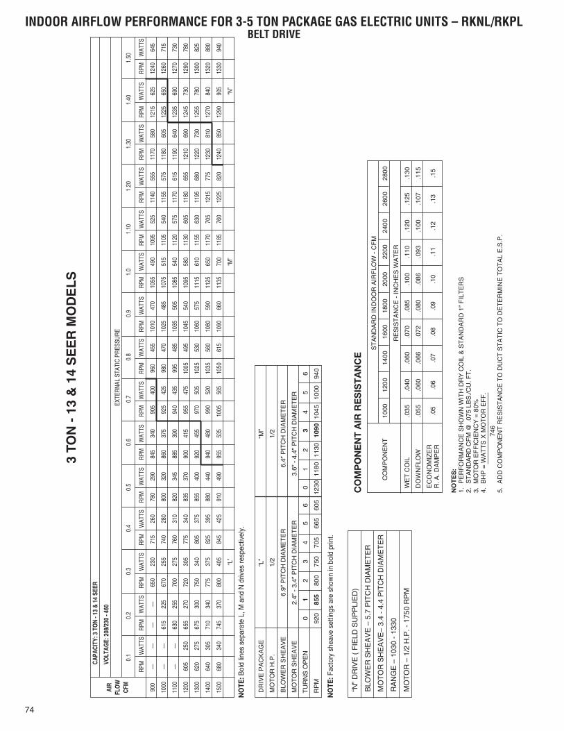
74
3 TO
N -
13
& 1
4 S
EE
R M
OD
EL
S
RPM
WAT
TS
——
——
——
605
250
620
275
640
305
680
340
RPM
WAT
TS
1010
470
1025
485
1035
505
1045
540
1060
575
1080
590
1090
660
RPM
WAT
TS
1240
645
1260
715
1270
730
1290
780
1300
825
1320
880
1330
940
CAPA
CITY
: 3 T
ON
- 13
& 14
SEE
R
VOLT
AGE:
208
/230
- 46
0
EXTE
RNAL
STA
TIC
PRES
SURE
0.1
0.2
0.3
0.4
0.5
0.6
0.7
0.8
0.9
1.0
1.10
1.20
1.30
1.40
1.50
900
1000
1100
1200
1300
1400
1500
RPM
WAT
TS
——
615
225
630
255
655
270
675
300
710
340
745
370
RPM
WAT
TS
650
230
670
255
700
275
720
305
750
340
775
375
800
405
“L”
RPM
WAT
TS
715
260
740
280
760
310
775
340
805
375
825
395
845
425
RPM
WAT
TS
780
290
800
320
820
345
835
370
855
400
880
440
910
490
RPM
WAT
TS
845
340
860
375
885
390
900
415
920
455
940
480
955
535
RPM
WAT
TS
905
400
925
425
940
435
955
475
970
505
990
520
1005
565
RPM
WAT
TS
960
455
980
470
995
485
1005
495
1025
530
1035
560
1050
615
RPM
WAT
TS
1055
490
1075
515
1085
540
1095
580
1115
610
1125
650
1135
700
“M”
RPM
WAT
TS
1095
525
1105
540
1120
575
1130
605
1155
630
1170
705
1185
760
RPM
WAT
TS
1140
555
1155
575
1170
615
1180
655
1195
680
1215
775
1225
820
RPM
WAT
TS
1170
580
1180
605
1190
640
1210
690
1220
730
1230
810
1240
850
RPM
WAT
TS
1215
625
1225
650
1235
690
1245
730
1255
780
1270
840
1290
905
“N”
AIR
FLO
WCF
M
DR
IVE
PA
CK
AG
E“L
”“M
”
MO
TO
R H
.P.
1/2
1/2
BLO
WE
R S
HE
AV
E6.
9�P
ITC
H D
IAM
ET
ER
6.4�
PIT
CH
DIA
ME
TE
R
MO
TO
R S
HE
AV
E2.
4�-
3.4�
PIT
CH
DIA
ME
TE
R3.
6�-
4.4�
PIT
CH
DIA
ME
TE
R
TU
RN
S O
PE
N0
12
34
56
01
23
45
6
RP
M92
085
580
075
070
566
560
512
3011
8011
3010
9010
4510
0094
0
ST
AN
DA
RD
IND
OO
R A
IRF
LOW
- C
FM
CO
MP
ON
EN
T10
0012
0014
0016
0018
0020
0022
0024
0026
0028
00
RE
SIS
TA
NC
E -
INC
HE
S W
AT
ER
WE
T C
OIL
.035
.040
.060
.070
.085
.100
.110
.120
.125
.130
DO
WN
FLO
W.0
55.0
60.0
66.0
72.0
80.0
86.0
93.1
00.1
07.1
15
EC
ON
OM
IZE
RR
. A. D
AM
PE
R.0
5.0
6.0
7.0
8.0
9.1
0.1
1.1
2.1
3.1
5
“N”
DR
IVE
( F
IELD
SU
PP
LIE
D)
BLO
WE
R S
HE
AV
E –
5.7
PIT
CH
DIA
ME
TE
R
MO
TO
R S
HE
AV
E–
3.4
- 4.
4 P
ITC
H D
IAM
ET
ER
RA
NG
E –
103
0 -
1330
MO
TO
R –
1/2
H.P
. - 1
750
RP
M
CO
MP
ON
EN
T A
IR R
ES
IST
AN
CE
NO
TE
S:
1.P
ER
FO
RM
AN
CE
SH
OW
N W
ITH
DR
Y C
OIL
& S
TA
ND
AR
D 1
�F
ILT
ER
S2.
ST
AN
DA
RD
CF
M @
.075
LB
S./C
U. F
T.
3.M
OT
OR
EF
FIC
IEN
CY
= 8
0%4.
BH
P =
WA
TT
S X
MO
TO
R E
FF
.74
65.
AD
D C
OM
PO
NE
NT
RE
SIS
TA
NC
E T
O D
UC
T S
TA
TIC
TO
DE
TE
RM
INE
TO
TA
L E
.S.P
.
INDOOR AIRFLOW PERFORMANCE FOR 3-5 TON PACKAGE GAS ELECTRIC UNITS – RKNL/RKPLBELT DRIVE
NO
TE: B
old
lines
sep
arat
e L,
M a
nd N
driv
es re
spec
tivel
y.
NO
TE: F
acto
ry s
heav
e se
tting
s ar
e sh
own
in b
old
prin
t.

75
3.5
TON
- 1
3 &
14
SE
ER
MO
DE
LS
RPM
WAT
TS
——
——
——
——
——
——
725
410
740
460
770
500
RPM
WAT
TS
995
420
1010
450
1030
500
1050
550
1065
600
1090
650
1105
700
1125
760
1145
835
RPM
WAT
TS
1265
630
1275
700
1290
760
1305
815
1325
900
1335
980
1350
1040
——
——
CAPA
CITY
: 3.5
TO
N - 1
3 &
14 S
EER
VOLT
AGE:
208
/230
- 46
0
EXTE
RNAL
STA
TIC
PRES
SURE
0.1
0.2
0.3
0.4
0.5
0.6
0.7
0.8
0.9
1.0
1.10
1.20
1.30
1.40
1.50
1000
1100
1200
1300
1400
1500
1600
1700
1800
RPM
WAT
TS
——
——
——
——
725
375
740
410
765
445
795
495
825
535
RPM
WAT
TS
735
305
750
320
770
350
800
395
830
420
855
480
875
510
900
550
925
605
RPM
WAT
TS
790
325
810
355
835
380
860
415
880
460
905
495
825
540
945
600
980
650
RPM
WAT
TS
850
360
870
380
885
410
905
445
925
490
950
540
975
570
1000
650
1010
710
RPM
WAT
TS
895
380
915
400
935
440
955
465
965
510
1000
590
1015
640
1020
690
1045
750
RPM
WAT
TS
945
400
965
415
985
450
1005
510
1015
560
1030
610
1055
660
1075
740
1100
790
RPM
WAT
TS
1060
455
1075
500
1090
540
1105
590
1120
640
1135
690
1145
745
1165
810
1185
900
“M”
RPM
WAT
TS
1105
490
1120
520
1130
580
1140
610
1150
665
1170
720
1185
800
1205
865
1225
960
RPM
WAT
TS
1145
520
1160
560
1170
600
1180
650
1190
710
1205
765
1225
860
1240
940
1270
1020
RPM
WAT
TS
1185
550
1195
590
1215
650
1230
710
1245
790
1260
860
1275
915
1290
1005
1315
1110
RPM
WAT
TS
1220
590
1240
640
1255
710
1270
790
1290
850
1310
920
1325
1005
1340
—
—— “N
”
AIR
FLO
WCF
M
DR
IVE
PA
CK
AG
E“L
”“M
”
MO
TO
R H
.P.
1/2
1/2
BLO
WE
R S
HE
AV
E6.
9�P
ITC
H D
IAM
ET
ER
6.9�
PIT
CH
DIA
ME
TE
R
MO
TO
R S
HE
AV
E2.
8�-
3.8�
PIT
CH
DIA
ME
TE
R4.
0�-
5.0�
PIT
CH
DIA
ME
TE
R
TU
RN
S O
PE
N0
12
34
56
01
23
45
6
RP
M95
894
590
586
582
077
072
512
2511
8511
4511
0010
6010
2010
00
ST
AN
DA
RD
IND
OO
R A
IRF
LOW
- C
FM
CO
MP
ON
EN
T10
0012
0014
0016
0018
0020
0022
0024
0026
0028
00
RE
SIS
TA
NC
E -
INC
HE
S W
AT
ER
WE
T C
OIL
.035
.040
.060
.070
.065
.100
.110
.120
.125
.130
DO
WN
FLO
W.0
55.0
60.0
66.0
72.0
80.0
86.0
93.1
00.1
07.1
15
EC
ON
OM
IZE
RR
. A. D
AM
PE
R.0
5.0
6.0
7.0
8.0
9.1
0.1
1.1
2.1
3.1
5
“N”
DR
IVE
( F
IELD
SU
PP
LIE
D)
BLO
WE
R S
HE
AV
E –
6.4
�P
ITC
H D
IAM
ET
ER
MO
TO
R S
HE
AV
E–
4.0�
- 5.
0�P
ITC
H D
IAM
ET
ER
RA
NG
E –
109
0 -
1365
MO
TO
R –
1/2
H.P
. - 1
750
RP
M
CO
MP
ON
EN
T A
IR R
ES
IST
AN
CE
NO
TE
S:
1.P
ER
FO
RM
AN
CE
SH
OW
N W
ITH
DR
Y C
OIL
& S
TA
ND
AR
D 1
�F
ILT
ER
S2.
ST
AN
DA
RD
CF
M @
.075
LB
S./C
U. F
T.
3.M
OT
OR
EF
FIC
IEN
CY
= 8
0%4.
BH
P =
WA
TT
S X
MO
TO
R E
FF
.74
65.
AD
D C
OM
PO
NE
NT
RE
SIS
TA
NC
E T
O D
UC
T S
TA
TIC
TO
DE
TE
RM
INE
TO
TA
L E
.S.P
.
RPM
WAT
TS
——
——
725
335
745
360
765
395
795
440
820
470
850
520
875
570
“L”
INDOOR AIRFLOW PERFORMANCE FOR 3-5 TON PACKAGE GAS ELECTRIC UNITS – RKNL/RKPLBELT DRIVE
NO
TE: B
old
lines
sep
arat
e L,
M a
nd N
driv
es re
spec
tivel
y.
NO
TE: F
acto
ry s
heav
e se
tting
s ar
e sh
own
in b
old
prin
t.

76
4 TO
N -
13
& 1
4 S
EE
R M
OD
EL
S
RPM
WAT
TS
——
——
——
——
——
——
775
470
800
525
830
595
RPM
WAT
TS
1015
505
1030
545
1050
600
1075
640
1095
680
1120
735
1150
800
1175
870
1200
950
RPM
WAT
TS
1320
705
1335
775
1345
825
1355
855
1370
935
1385
1000
——
——
——
CAPA
CITY
: 4 T
ON
- 13
& 14
SEE
R
VOLT
AGE:
208
/230
- 46
0
EXTE
RNAL
STA
TIC
PRES
SURE
0.1
0.2
0.3
0.4
0.5
0.6
0.7
0.8
0.9
1.0
1.10
1.20
1.30
1.40
1.50
1200
1300
1400
1500
1600
1700
1800
1900
2000
RPM
WAT
TS
——
——
——
——
775
425
795
470
820
515
855
560
885
640
RPM
WAT
TS
780
360
805
390
825
425
850
475
870
495
900
540
930
600
955
650
970
710
RPM
WAT
TS
835
390
855
410
870
445
900
490
920
530
940
560
960
625
995
700
1020
790
RPM
WAT
TS
885
410
910
450
925
480
940
515
960
580
980
605
1010
680
1035
755
1065
840
RPM
WAT
TS
935
440
950
470
960
510
980
550
1005
605
1025
655
1050
740
1075
800
1115
860
RPM
WAT
TS
975
475
990
510
1010
550
1025
600
1050
660
1075
715
1100
760
1130
840
1180
900
RPM
WAT
TS
1070
550
1085
590
1105
615
1125
670
1145
710
1165
770
1190
840
1220
920
1240
1010
“M”
RPM
WAT
TS
1120
570
1135
610
1155
650
1175
700
1195
755
1215
810
1235
890
1260
955
1295
1060
RPM
WAT
TS
1170
600
1185
640
1200
700
1220
745
1235
800
1270
870
1280
930
1305
1010
1330
1105
RPM
WAT
TS
1220
635
1235
685
1245
730
1270
780
1285
845
1305
915
1330
985
1350
1070
1375
1160
RPM
WAT
TS
1265
655
1285
730
1300
770
1315
825
1330
890
1350
940
1365
1020
1385
1115
—— “N
”
AIR
FLO
WCF
M
DR
IVE
PA
CK
AG
E“L
”“M
”
MO
TO
R H
.P.
1/2
3/4
BLO
WE
R S
HE
AV
E6.
4�P
ITC
H D
IAM
ET
ER
5.7�
PIT
CH
DIA
ME
TE
R
MO
TO
R S
HE
AV
E2.
8�-
3.8�
PIT
CH
DIA
ME
TE
R3.
4�-
4.4�
PIT
CH
DIA
ME
TE
R
TU
RN
S O
PE
N0
12
34
56
01
23
45
6
RP
M10
6010
0095
591
086
582
577
013
8513
3012
8012
2511
7511
2010
60
ST
AN
DA
RD
IND
OO
R A
IRF
LOW
- C
FM
CO
MP
ON
EN
T10
0012
0014
0016
0018
0020
0022
0024
0026
0028
00
RE
SIS
TA
NC
E -
INC
HE
S W
AT
ER
WE
T C
OIL
.035
.040
.060
.070
.085
.100
.110
.120
.125
.130
DO
WN
FLO
W.0
55.0
60.0
66.0
72.0
80.0
86.0
93.1
00.1
07.1
15
EC
ON
OM
IZE
RR
. A. D
AM
PE
R.0
5.0
6.0
7.0
8.0
9.1
0.1
1.1
2.1
3.1
5
CO
MP
ON
EN
T A
IR R
ES
IST
AN
CE
NO
TE
S:
1.P
ER
FO
RM
AN
CE
SH
OW
N W
ITH
DR
Y C
OIL
& S
TA
ND
AR
D 1
�F
ILT
ER
S2.
ST
AN
DA
RD
CF
M @
.075
LB
S./C
U. F
T.
3.M
OT
OR
EF
FIC
IEN
CY
= 8
0%4.
BH
P =
WA
TT
S X
MO
TO
R E
FF
.74
65.
AD
D C
OM
PO
NE
NT
RE
SIS
TA
NC
E T
O D
UC
T S
TA
TIC
TO
DE
TE
RM
INE
TO
TA
L E
.S.P
.
RPM
WAT
TS
——
——
770
385
790
425
815
455
850
505
875
555
910
610
940
670
“L”
INDOOR AIRFLOW PERFORMANCE FOR 3-5 TON PACKAGE GAS ELECTRIC UNITS – RKNL/RKPLBELT DRIVE
NO
TE: B
old
lines
sep
arat
e L,
M a
nd N
driv
es re
spec
tivel
y.
NO
TE: F
acto
ry s
heav
e se
tting
s ar
e sh
own
in b
old
prin
t.

77
5 TO
N -
13
SE
ER
MO
DE
LS
RPM
WAT
TS
——
——
——
——
780
455
800
485
830
550
860
615
895
680
940
755
970
825
1015
910
RPM
WAT
TS
1065
570
1080
615
1105
680
1120
725
1140
785
1160
850
1180
910
1210
995
1240
1055
1265
1125
1300
1210
1360
1350
“M”
RPM
WAT
TS
1340
745
1355
805
1365
880
1375
940
1390
1020
1405
1100
——
——
——
——
——
——
CAPA
CITY
: 5 T
ON
- 13
SEER
VOLT
AGE:
208
/230
- 46
0
EXTE
RNAL
STA
TIC
PRES
SURE
0.1
0.2
0.3
0.4
0.5
0.6
0.7
0.8
0.9
1.0
1.10
1.20
1.30
1.40
1.50
1400
1500
1600
1700
1800
1900
2000
2100
2200
2300
2400
2500
RPM
WAT
TS
——
——
780
390
795
450
815
470
850
530
880
605
915
655
945
735
975
795
1015
880
1040
935
“L”
RPM
WAT
TS
815
385
840
415
870
470
895
530
915
560
945
640
970
700
1005
760
1030
830
1065
910
1100
1005
1145
1100
RPM
WAT
TS
875
425
895
440
915
510
940
570
965
615
995
675
1015
730
1040
820
1060
880
1100
965
1145
1055
1170
1140
RPM
WAT
TS
930
460
945
500
965
560
990
605
1010
660
1035
720
1055
790
1090
870
1120
940
1150
1050
1175
1085
1200
1175
RPM
WAT
TS
970
490
995
540
1015
600
1035
640
1055
710
1070
775
1105
830
1130
910
1155
980
1180
1050
1225
1140
1260
1215
RPM
WAT
TS
1030
540
1045
595
1060
640
1075
680
1100
760
1120
810
1145
875
1170
950
1195
1020
1225
1095
1260
1175
1305
1270
RPM
WAT
TS
1105
595
1135
650
1145
705
1160
755
1175
810
1200
890
1225
950
1250
1020
1275
1100
1310
1175
1340
1255
1400
1390
RPM
WAT
TS
1150
615
1165
675
1180
730
1200
790
1225
850
1245
915
1260
980
1290
1060
1320
1140
1350
1230
1370
1315
——
RPM
WAT
TS
1195
645
1215
700
1225
750
1245
815
1260
880
1290
960
1320
1035
1335
1100
1360
1180
1375
1260
1400
1375
——
RPM
WAT
TS
1235
660
1255
735
1275
790
1300
855
1320
930
1335
1000
1350
1075
1370
1150
1385
1225
1405
1320
——
——
RPM
WAT
TS
1300
705
1320
775
1340
840
1355
905
1365
985
1375
1050
1385
1120
1400
1200
——
——
——
——
AIR
FLO
WCF
M
DR
IVE
PA
CK
AG
E“L
”“M
”
MO
TO
R H
.P.
3/4
1
BLO
WE
R S
HE
AV
E6.
4�P
ITC
H D
IAM
ET
ER
6.4�
PIT
CH
DIA
ME
TE
R
MO
TO
R S
HE
AV
E2.
8�-
3.8�
PIT
CH
DIA
ME
TE
R -
AD
J.3.
4�-
4.4�
PIT
CH
DIA
ME
TE
R -
AD
J.
TU
RN
S O
PE
N0
12
34
56
01
23
45
6
RP
M10
9510
4099
594
089
083
578
014
0513
6013
0512
5011
9511
4510
95
ST
AN
DA
RD
IND
OO
R A
IRF
LOW
- C
FM
CO
MP
ON
EN
T10
0012
0014
0016
0018
0020
0022
0024
0026
0028
00
RE
SIS
TA
NC
E -
INC
HE
S W
AT
ER
WE
T C
OIL
.035
.040
.060
.070
.085
.100
.110
.120
.125
.130
DO
WN
FLO
W.0
55.0
60.0
66.0
72.0
80.0
86.0
93.1
00.1
07.1
15
EC
ON
OM
IZE
RR
. A. D
AM
PE
R.0
5.0
6.0
7.0
8.0
9.1
0.1
1.1
2.1
3.1
5
CO
MP
ON
EN
T A
IR R
ES
IST
AN
CE
NO
TE
S:
1.P
ER
FO
RM
AN
CE
SH
OW
N W
ITH
DR
Y C
OIL
& S
TA
ND
AR
D 1
�F
ILT
ER
S2.
ST
AN
DA
RD
CF
M @
.075
LB
S./C
U. F
T.
3.M
OT
OR
EF
FIC
IEN
CY
= 8
0%4.
BH
P =
WA
TT
S X
MO
TO
R E
FF
.74
65.
AD
D C
OM
PO
NE
NT
RE
SIS
TA
NC
E T
O D
UC
T S
TA
TIC
TO
DE
TE
RM
INE
TO
TA
L E
.S.P
.
RPM
WAT
TS
780
370
795
405
805
425
840
490
870
540
895
590
930
655
955
705
995
780
1015
830
1040
925
1095
1040
INDOOR AIRFLOW PERFORMANCE FOR 3-5 TON PACKAGE GAS ELECTRIC UNITS – RKNLBELT DRIVE
NO
TE: B
old
lines
sep
arat
e L,
M a
nd N
driv
es re
spec
tivel
y.
NO
TE: F
acto
ry s
heav
e se
tting
s ar
e sh
own
in b
old
prin
t.

78
5 TO
N -
14
SE
ER
MO
DE
LS
AIR
FLO
W P
ERFO
RM
AN
CE
- 5 T
ON
[17.
6 kW
] BEL
T D
RIV
E
0.1
[0.0
2]0.
2[0
.05]
0.3
[0.0
7]0.
4[0
.10]
0.5
[0.1
2]0.
6[0
.15]
0.7
[0.1
7]0.
8[0
.20]
0.9
[0.2
2]1.
0[0
.25]
1.1
[0.2
7]1.
2[0
.30]
1.3
[0.3
2]1.
4[0
.35]
1.5
[0.3
7]R
PMW
RPM
WR
PMW
RPM
WR
PMW
RPM
WR
PMW
RPM
WR
PMW
RPM
WR
PMW
RPM
WR
PMW
RPM
WR
PMW
1400
[661
]—
——
——
—79
439
583
543
387
746
791
849
996
252
810
1155
610
8561
011
1866
811
5272
311
8777
612
2082
712
5087
615
00[7
08]
——
——
——
810
440
851
478
892
512
934
544
978
573
1026
601
1087
666
1120
724
1154
779
1189
832
1222
883
1252
932
1600
[755
]—
——
—78
944
683
048
987
152
791
356
295
459
399
862
310
5966
810
9072
911
2378
611
5884
211
9389
412
2694
512
5599
517
00[8
02]
——
——
813
501
854
544
896
582
937
616
979
648
1023
677
1065
736
1096
797
1129
855
1164
910
1199
963
1232
1014
1262
1063
1800
[849
]—
—79
947
084
056
088
260
492
364
296
467
610
0670
810
4474
710
7481
111
0587
211
3993
011
7398
512
0810
3812
4110
8912
7111
3819
00[8
97]
788
507
828
574
869
625
910
668
952
706
993
741
1035
772
1057
828
1087
892
1118
953
1151
1011
1186
1066
1221
1119
1254
1170
1283
1219
2000
[944
]81
757
885
764
489
869
593
973
998
177
710
2281
110
4484
810
7391
611
0398
011
3410
4111
6810
9912
0211
5412
3712
0712
7012
5813
0013
0721
00[9
91]
845
653
885
720
927
771
968
814
1009
852
1035
869
1064
943
1093
1011
1123
1075
1154
1136
1187
1194
1222
1249
1256
1302
1290
1353
——
2200
[103
8]87
373
491
380
195
585
299
689
610
3793
410
5797
110
8610
4411
1511
1311
4511
7711
7612
3812
1012
9512
4413
5012
7914
03—
——
—23
00[1
085]
902
821
942
888
983
939
1024
983
1049
1000
1081
1080
1111
1153
1140
1222
1169
1286
1201
1347
1234
1404
1269
1459
——
——
——
2400
[113
3]93
391
497
398
110
1410
3210
3610
2810
7511
1611
0711
9611
3712
7011
6513
3811
9514
0212
2714
63—
——
——
——
——
—25
00[1
180]
970
1013
1010
1080
1035
1052
1062
1152
1101
1240
1133
1320
1163
1393
1191
1462
——
——
——
——
——
——
——
NO
TE: L
-Driv
e le
ft of
bol
d lin
e, M
-Driv
e rig
ht o
f bol
d lin
e.
01
23
45
01
23
45
1007
963
922
880
833
785
1272
1242
1210
1172
1130
1089
NO
TE: F
acto
ry s
heav
e se
tting
s ar
e sh
own
in b
old
prin
t.
[ ] D
esig
nate
s M
etric
Con
vers
ions
Cap
acity
5
Ton
[17.
6kW
] —
14
SEER
Exte
rnal
Sta
tic P
ress
ure
— In
ches
of W
ater
[kPa
]
Volta
ge
20
8/23
0-46
0 —
3 p
hase
Air
CFM
[L/s
]Fl
ow
Driv
e P
acka
geM
otor
H.P
. [W
]B
low
er S
heav
eM
otor
She
ave
Turn
s O
pen
RP
M
L¾
[559
]6.
9" P
itch
Dia
met
er2.
8"-3
.8" P
itch
Dia
met
er -
Adj
.
M1
[746
]6.
9" P
itch
Dia
met
er4.
0"-5
.0" P
itch
Dia
met
er -
Adj
.
ST
AN
DA
RD
IND
OO
R A
IRF
LOW
- C
FM
CO
MP
ON
EN
T10
0012
0014
0016
0018
0020
0022
0024
0026
0028
00
RE
SIS
TA
NC
E -
INC
HE
S W
AT
ER
WE
T C
OIL
.035
.040
.060
.070
.085
.100
.110
.120
.125
.130
DO
WN
FLO
W.0
55.0
60.0
66.0
72.0
80.0
86.0
93.1
00.1
07.1
15
EC
ON
OM
IZE
RR
. A. D
AM
PE
R.0
5.0
6.0
7.0
8.0
9.1
0.1
1.1
2.1
3.1
5
CO
MP
ON
EN
T A
IR R
ES
IST
AN
CE
NO
TE
S:
1.P
ER
FO
RM
AN
CE
SH
OW
N W
ITH
DR
Y C
OIL
& S
TA
ND
AR
D 1
�F
ILT
ER
S2.
ST
AN
DA
RD
CF
M @
.075
LB
S./C
U. F
T.
3.M
OT
OR
EF
FIC
IEN
CY
= 8
0%4.
BH
P =
WA
TT
S X
MO
TO
R E
FF
.74
65.
AD
D C
OM
PO
NE
NT
RE
SIS
TA
NC
E T
O D
UC
T S
TA
TIC
TO
DE
TE
RM
INE
TO
TA
L E
.S.P
.
INDOOR AIRFLOW PERFORMANCE FOR 3-5 TON PACKAGE GAS ELECTRIC UNITS – RKPLBELT DRIVE
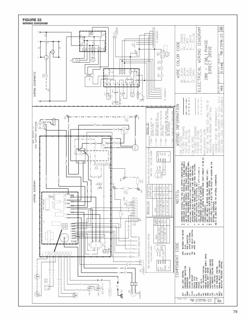
79
FIGURE 23WIRING DIAGRAM
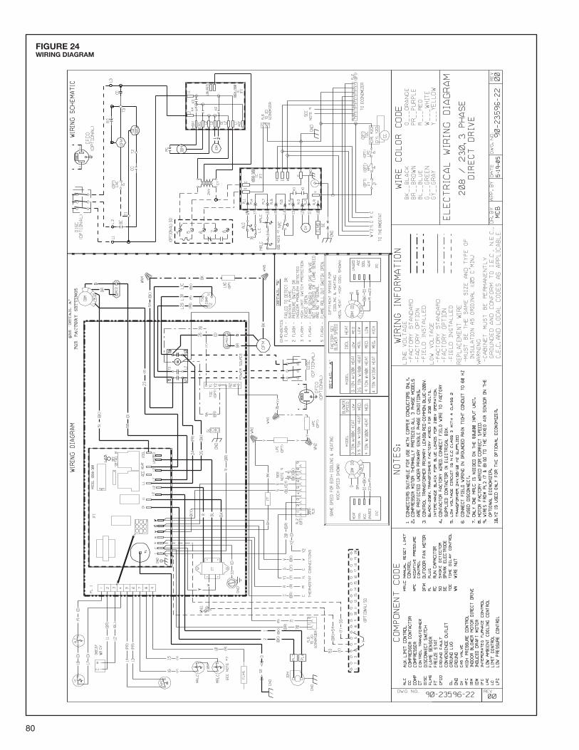
80
FIGURE 24WIRING DIAGRAM

81
FIGURE 25WIRING DIAGRAM

82
FIGURE 26WIRING DIAGRAM

83
FIGURE 27WIRING DIAGRAM

84
FIGURE 28WIRING DIAGRAM

85
FIGURE 29WIRING DIAGRAM

86
FIGURE 30SYSTEM CHARGE CHARTS
175
200
225
250
275
300
325
350
375
400
425
450
475
500
525
120 125 130 135 140 145 150 155 160 165 170
55
65
75
85
95
105
115
92-102259-01-01
3 TON COOLING - 13 & 14 SEER
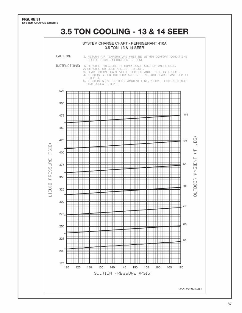
87
FIGURE 31SYSTEM CHARGE CHARTS
3.5 TON COOLING - 13 & 14 SEER

88
FIGURE 32SYSTEM CHARGE CHARTS
4 TON COOLING - 13 & 14 SEER
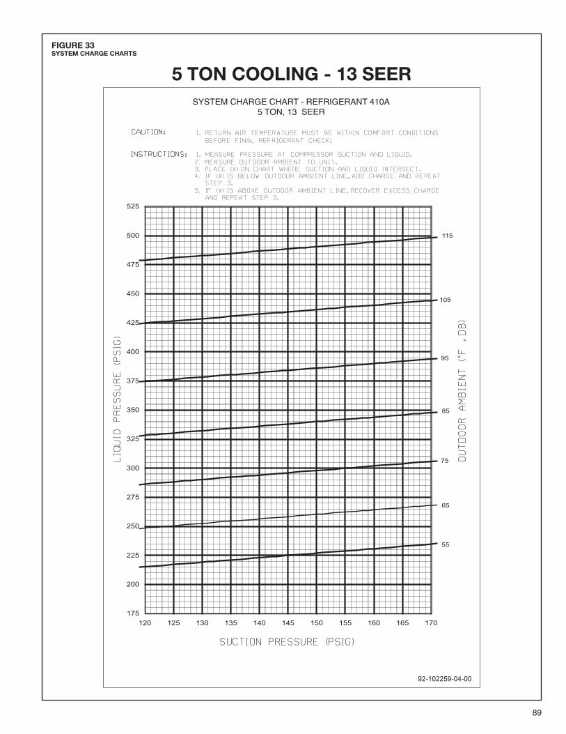
89
FIGURE 33SYSTEM CHARGE CHARTS
5 TON COOLING - 13 SEER

90
FIGURE 34SYSTEM CHARGE CHARTS
92-102259-05-00
SYSTEM CHARGE CHART - REFRIGERANT 410A5 TON, 14 SEER
55
65
75
85
95
105
115
175
200
225
250
275
300
325
350
375
400
425
450
475
500
525
120 125 130 135 140 145 150 155 160 165 170
5 TON COOLING - 14 SEER

91
WARNING!
COOLING TROUBLE SHOOTING CHART
DISCONNECT ALL POWER TO UNIT BEFORE SERVICING. CONTACTOR MAY BREAK ONLY ONE SIDE. FAILURETO SHUT OFF POWER CAN CAUSE ELECTRICAL SHOCK RESULTING IN PERSONAL INJURY OR DEATH.
SYMPTOM POSSIBLE CAUSE REMEDY
Unit will not run • Power off or loose electrical connection • Check for correct voltage at compressor contactor in controlbox
• Thermostat out of calibration-set too high • Reset• Failed contactor • Check for 24 volts at contactor coil - replace if contacts are
open• Blown fuses • Replace fuses• Transformer defective • Check wiring-replace transformer• High pressure control open (if provided) • Reset-also see high head pressure remedy-The high pressure
control opens at 610 PSIG• Interconnecting low voltage wiring damaged • Replace thermostat wiring
Condenser fan runs, compressor • Run or start capacitor failed (single phase only) • Replacedoesn’t • Start relay defective 9single phase only) • Replace
• Loose connection • Check for correct voltage at compressor -check & tighten all connections
• Compressor stuck, grounded or open motor winding • Wait at least 2 hours for overload to reset.open internal overload. If still open, replace the compressor.
• Low voltage condition At compressor terminals, voltage must be within 10% of ratingplate volts when unit is operating.
• Low voltage condition • Add start kit components
Insufficient cooling • Improperly sized unit • Recalculate load• Improper airflow • Check - should be approximately 400 CFM per ton.• Incorrect refrigerant charge • Charge per procedure attached to unit service panel.• Air, non-condensibles or moisture in system • Recover refrigerant, evacuate & recharge, add filter drier• Incorrect voltage • At compressor terminals, voltage must be within 10% of rating
plate volts when unit is operating.
Compressor short cycles • Incorrect voltage • At compressor terminals, voltage must be ± 10% ofnameplate marking when unit is operating.
• Defective overload protector • Replace - check for correct voltage• Refrigerant undercharge • Add refrigerant
Registers sweat • Low evaporator airflow • Increase speed of blower or reduce restriction - replace airfilter
High head-low vapor pressures • Restriction in liquid line, expansion device or filter drier • Remove or replace defective component• Flow check piston size too small • Change to correct size piston• Incorrect capillary tubes • Change coil assembly• TXV does not open • Replace TXV
High head-high or normal vapor • Dirty condenser coil • Clean coilpressure - Cooling mode • Refrigerant overcharge • Correct system charge
• Condenser fan not running • Repair or replace• Air or non-condensibles in system • Recover refrigerant, evacuate & recharge
Low head-high vapor pressures • Defective Compressor valves • Replace compressor• Incorrect capillary tubes • Replace coil assembly
Low vapor - cool compressor - • Low evaporator airflow • Increase speed of blower or reduce restriction - replace airiced evaporator coil filter
• Operating below 65°F outdoors • Add Low Ambient Kit• Moisture in system • Recover refrigerant - evacuate & recharge - add filter drier
High vapor pressure • Excessive load • Recheck load calculation• Defective compressor • Replace
Fluctuating head & vapor • TXV hunting • Check TXV bulb clamp - check air distribution on coil - replacepressures TXV
• Air or non-condensibles in system • Recover refrigerant, evacuate & recharge
Gurgle or pulsing noise at • Air or non-condensibles in system • Recover refrigerant, evacuate & rechargeexpansion device or liquid line
Circulating air blower & inducer • Manual reset overtemperature control • Reset or replacerun continuously, • tripped
compressor will not start • Wire loose in limit circuit • Check wiring

92
FURNACE TROUBLESHOOTING GUIDE(COMBINATION HEATING AND COOLING UNITS WITH DIRECT SPARK IGNITION)
SET THERMOSTAT TOCALL FOR HEAT
SET FAN SWITCH TO AUTO
START
WARNINGDISCONNECT POWER BEFORESERVICING.SERVICE MUST BE BY A TRAINED,QUALIFIED SERVICE TECHNICIAN.
HAZARDOUS VOLTAGELINE VOLTAGE CON-
NECTIONS
FLOW CHART CONTINUED ON NEXT PAGE
NO
YESYES
YES
YES
NO
NO
NO
!
INDUCED DRAFT BLOWERMOTOR STARTS
15 SECOND PREPURGE
REPLACE INTEGRATEDCONTROL BOARD (IFC)
REPLACE INDUCEDDRAFT BLOWER
NO
REPLACE NEGATIVEPRESSURE SWITCH
REPLACE INTEGRATEDCONTROL BOARD (IFC)
IF WIRING IS OK
CHECK FOR EXHAUST,INTAKE OR HEAT
EXCHANGER BLOCKAGEAND RESET CONTROLNO
REPLACE IGNITION CON-TROL
YES
REPLACE VALVE
• CHECK LINE VOLTAGE TO CONTROL BOARD• CHECK LOW VOLTAGE TRANSFORMER• CHECK WIRING
• CHECK FOR 208-230 VAC TO IOM MOTOR
• CHECK IGNITOR CABLE• CHECK SPARK IGNITOR POSITION AND CONDITION
• IS NEGATIVE PRESSURE SWITCH CLOSED?
• CHECK FOR OPEN ROLL-OUT CONTROL
• CHECK FOR OPEN LIMIT
• CHECK IGNITION CONTROL CHASSIS GROUND WIRE
• CHECK WIRING
• CHECK INLET GAS PRESSURE
• CHECK 24 VOLTS TO GAS VALVE
• CHECK FOR GAS FLOW TO AND FROM VALVE
• CHECK BURNER CARRYOVER
NOTE: THE SYSTEM WILL ATTEMPT TO LIGHT 3 TIMES WITH A 60 SECOND INTER-PURGE BETWEEN TRIES. IF AFTER THE THIRD TIME THE BURNERSDO NOT LIGHT, THE SYSTEM WILL LOCK OUT. IF THE UNIT IS EQUIPPED WITHA UNITED TECH. OR JOHNSON CONTROLS IGNITION CONTROL, THE SYSTEMWILL ATTEMPT TO LIGHT 3 TIMES EACH HOUR UNTIL THE BURNERS LIGHT ORTHE THERMOSTAT IS RESET.
YES
YES
IGNITOR SPARKS
MAIN BURNER LIGHTS
NO
• CHECK NEGATIVE PRESSURESWITCH SENSING TUBE
• CHECK FOR EXHAUSTBLOCKAGE
YES
YES
YES
REPLACE IGNITOR/CABLE ASSEMBLY
REPLACE LIMITIF UNIT IS COLD
NO

93
NOTE: IF THE SYSTEM GOES INTO LOCKOUT, WAIT30 SECONDS AND RESET THE SYSTEM.
• CHECK FLAME SENSOR POSITION AND CONDITION
• CLEAN FLAME SENSOR WITH STEEL WOOL
• CHECK FLAME SENSOR WIRES AND CONNECTIONS
• CHECK FOR 208-230 VAC ACROSS BLOWERMOTOR TERMINALS ON CONTROL BOARD
• CHECK CAPACITOR
YES
YES
NOMAIN BURNER FLAME SUSTAINED
YES
NOINDOOR BLOWER MOTOR STARTSAFTER 30 SECONDS
REPLACE SENSOR
NO REPLACE INTEGRATEDCONTROL BOARD (IFC)
NO REPLACE INTEGRATEDCONTROL BOARD (IFC)
NO
REPLACE IGNITION CON-TROL
YES
YES
REPLACE BLOWERMOTOR
• CHECK FOR OPEN LIMIT
• CHECK FOR OPEN ROLL-OUT CONTROL
• CHECK FOR PROPER THERMOSTAT OPERATION• REMOVE VALVE LEAD AT GAS VALVE
IF VALVE CLOSES, RECHECK THE THERMOSTATAND WIRING. IF OK, THEN REPLACE VALVE
• CHECK FOR OPEN LIMIT OR ROLL-OUT CONTROL
YES
NOSYSTEM RUNS UNTILCALL FOR HEAT ENDS
• CHECK FOR EXHAUST OR INTAKE BLOCKAGE.CLEAR BLOCKAGE AND RESET CONTROL
• CHECK FOR DIRTY FILTERS• CHECK FOR RESTRICTED AIRFLOW
TROUBLESHOOTING ENDS
REPEAT PROCEDURE UNTIL TROUBLE FREEOPERATION IS OBTAINED.
YES
NOTURN THERMOSTAT OFFVALVE SHUTS OFFFLAME SHUTS OFF
YES
NOINDUCED DRAFT MOTOR STOPSAFTER 5 SECOND POSTPURGE
YES
YES
• CHECK FOR DIRTY FILTERS• CHECK FOR RESTRICTED
AIR-FLOW
CHECK FOR EXHAUST,INTAKE OR HEAT EXCHANG-
ER BLOCKAGECLEAR BLOCKAGE AND
RESET CONTROL
YES
NOINDOOR BLOWER MOTOR STOPSAFTER 90 SECONDS

94

95

96 CM 0606