rm5g series simple version operation manual - …°¡易版英文操作手冊1023...1 2014.10.23...
TRANSCRIPT
1
http://www.rhymebus.com.tw
2014.10.23 Edition Thank you for using RHYMEBUS RM5G series drive. For proper operations and safety purposes, please read complete manual carefully (enclose CD inside the box) or visit RHYMEBUS website: http://www.rhymebus.com.tw to download the operation manual. To prevent any possible dangers ,only the qualified personnel may proceed with the installation. Please pay attention to the safety precautions marked with “DANGER” or “CAUTION” in complete manual before installation.
DANGER
User may cause the casualty or serious damages if user does not abide by the instructions of the manual to execute the tasks.
CAUTION
User may cause injuries to the people or damage the equipment if user does not abide by the instructions of the manual to execute the tasks.
Pow
er
Sourc
e R,S
(L,N) AC power source input terminals
Single-phase; sinusoidal power source input terminals.
R,S,T (L1,L2,L3)
Three-phase; sinusoidal power source input terminals.
○+ DC power source
input terminals External DC power source terminal. ※Only 2007 ~ 2015, 4007 ~ 4020 models have the terminal.
Moto
r
U,V,W (T1,T2,T3)
Drive outputs to motor terminals
Output three-phase variable frequency and voltage to motor.
Pow
er
and B
rakin
g
P(+), N○- Dynamic brake unit
terminal The terminalscan connect to dynamic braking unit(option). P○+, N○-
P, N
P, PR External
brakingresistor terminal
The terminals can connect to external brake resistor (option).
P(+), PR
P○+, PR
P(+), P1 External reactor terminal
The terminal can connect to DC reactor (DCL) for improving power factor. The default setting is connected by a jumper. P○+, P1
Gro
undin
g
PE(or G) Grounding terminal
Ground the drive in compliance with the NEC standard or local electrical code.
RM5G Series Simple Version
Operation Manual
Terminals of Main Circuit

2
RM5G IM
R/L1
S/L2
W/T3
V/T2
G
U/T1
PR P N Induction Motor
T/L3
※2: Braking Resistor(option)
R/L1
S/L2
G
T/L3
Model: RM5G-1001/2-1PH~RM5G-1002-1PH ; RM5G-2001/2-1PH~RM5G-2002-1PHModel: RM5G-2001/2~RM5G-2005 ; RM5G-4001~RM5G-4005 RM5P-2001~RM5P-2005; RM5P-4002~RM5P-4007
※Single-Phase connect to
R/L1,S/L2 terminal.
※Three-Phase connect to
R/L1,S/L2 ,T/L3 terminal.
RM5G/P IM
R/L1
S/L2
W/T3
V/T2
U/T1
Induction Motor
T/L3
R/L1
S/L2
T/L3
N
※2:Braking Resistor
(option)
Jumper
P(+)PR P1
※1:DC Reactor(DCL; option)
RM5G/P IM
R/L1
S/L2
W/T3
V/T2
U/T1
Induction Motor
T/L3
R/L1
S/L2
T/L3
N
Jumper
P(+) P1
※1:DC Reactor(DCL; option)
Model: RM5G-2007 ~ RM5G-2015; RM5P-2010 ~ RM5P-2020;
Model: RM5G-4007 ~ RM5G-4025; RM5P-4010 ~ RM5P-4030
Model: RM5G-2020 ~ RM5G-2040;RM5P-2025 ~ RM5P-2050;
Model: RM5G-4030 ~ RM5G-4060; RM5P-4040 ~ RM5P-4075
RM5G/P IM
R/L1
S/L2
W/T3
V/T2
U/T1
Induction Motor
T/L3
R/L1
S/L2
T/L3
N
Jumper
P(+) P1
※1: DC Reactor(DCL; option)
Three-Phase
50/60Hz AC Power Input
※2:Braking Resistor(option)
PR
Three-Phase,
50/60Hz AC Power Input
Three-Phase,
50/60Hz AC Power Input
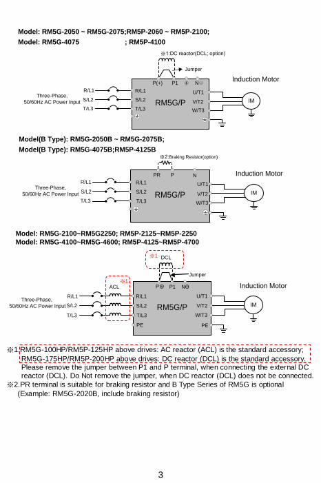
Model(B Type): RM5G-2020B ~ RM5G-2040B;RM5P-2025B ~ RM5P-2050B;
Model(B Type): RM5G-4030B ~ RM5G-4060B; RM5P-4040B ~ RM5P-4075B
3
RM5G/P IM
R/L1
S/L2
W/T3
V/T2
U/T1
Induction Motor
T/L3
R/L1
S/L2
T/L3
NP
Three-Phase,
50/60Hz AC Power Input
※2:Braking Resistor(option)
Model(B Type): RM5G-2050B ~ RM5G-2075B;
Model(B Type): RM5G-4075B;RM5P-4125B
PR
RM5G/P IM
R/L1
S/L2
W/T3
V/T2
PE
U/T1
P P1 NӨ
Three-Phase,
50/60Hz AC Power Input
Induction Motor
T/L3
PE
R/L1
S/L2
T/L3
DCL
※1ACL
Jumper
+
Model: RM5G-2100~RM5G2250; RM5P-2125~RM5P-2250
Model: RM5G-4100~RM5G-4600; RM5P-4125~RM5P-4700
RM5G/P IM
R/L1
S/L2
W/T3
V/T2
U/T1
Induction Motor
T/L3
R/L1
S/L2
T/L3
Three-Phase,
50/60Hz AC Power Input
Model: RM5G-2050 ~ RM5G-2075;RM5P-2060 ~ RM5P-2100;
Model: RM5G-4075 ; RM5P-4100
※1
N
Jumper
P(+) P1
※1:DC reactor(DCL; option)
※1.RM5G-100HP/RM5P-125HP above drives: AC reactor (ACL) is the standard accessory;
RM5G-175HP/RM5P-200HP above drives: DC reactor (DCL) is the standard accessory. Please remove the jumper between P1 and P terminal, when connecting the external DC reactor (DCL). Do Not remove the jumper, when DC reactor (DCL) does not be connected.
※2.PR terminal is suitable for braking resistor and B Type Series of RM5G is optional
(Example: RM5G-2020B, include braking resistor)
4
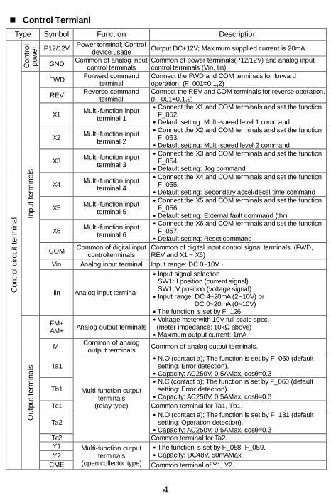
Control Termianl
Type Symbol Function Description
Contr
ol circuit t
erm
inal
Contr
ol
pow
er P12/12V
Power terminal; Control device usage
Output DC+12V; Maximum supplied current is 20mA.
GND Common of analog input
control terminals Common of power terminals(P12/12V) and analog input control terminals (Vin, Iin).
Input
term
inals
FWD Forward command
terminal Connect the FWD and COM terminals for forward operation. (F_001=0,1,2)
REV Reverse command
terminal Connect the REV and COM terminals for reverse operation. (F_001=0,1,2)
X1 Multi-function input
terminal 1
․Connect the X1 and COM terminals and set the function F_052.
․Default setting: Multi-speed level 1 command
X2 Multi-function input
terminal 2
․Connect the X2 and COM terminals and set the function F_053.
․Default setting: Multi-speed level 2 command
X3 Multi-function input
terminal 3
․Connect the X3 and COM terminals and set the function F_054.
․Default setting: Jog command
X4 Multi-function input
terminal 4
․Connect the X4 and COM terminals and set the function F_055.
․Default setting: Secondary accel/decel time command
X5 Multi-function input
terminal 5
․Connect the X5 and COM terminals and set the function F_056.
․Default setting: External fault command (thr)
X6 Multi-function input
terminal 6
․Connect the X6 and COM terminals and set the function F_057.
․Default setting: Reset command
COM Common of digital input
controlterminals Common of digital input control signal terminals. (FWD, REV and X1 ~ X6)
Vin Analog input terminal Input range: DC 0~10V。
Iin Analog input terminal
․Input signal selection SW1: I position (current signal) SW1: V position (voltage signal)
․Input range: DC 4~20mA (2~10V) or DC 0~20mA (0~10V)
․The function is set by F_126.
Outp
ut te
rmin
als
FM+ AM+
Analog output terminals ․Voltage meterwith 10V full scale spec.
(meter impedance: 10kΩ above) ․Maximum output current: 1mA
M- Common of analog
output terminals Common of analog output terminals.
Ta1
Multi-function output terminals
(relay type)
․N.O (contact a); The function is set by F_060 (default setting: Error detection).
․Capacity: AC250V, 0.5AMax, cosθ=0.3
Tb1 ․N.C (contact b); The function is set by F_060 (default
setting: Error detection). ․Capacity: AC250V, 0.5AMax, cosθ=0.3
Tc1 Common terminal for Ta1, Tb1.
Ta2 ․N.O (contact a); The function is set by F_131 (default
setting: Operation detection). ․Capacity: AC250V, 0.5AMax, cosθ=0.3
Tc2 Common terminal for Ta2.
Y1 Multi-function output terminals
(open collector type)
․The function is set by F_058, F_059. ․Capacity: DC48V, 50mAMax Y2
CME Common terminal of Y1, Y2.

5
Voltage Selection Board of Cooling Fan
Description of Terminal and Wiring Diagram
RM5G
SINK
SOURCE
I
V
FWD
REVX1
X2
X3
X4
12V
Vin
Iin
GNDCME
Y2
Y1
Tc1
Tb1
Ta1
Tc2
Ta2
FM+
AM+
P P P
VR
1KΩ,1/4W
ForwardReverse
Multi-function Input Terminal 1
(-)
(+)
(+)
Multi-function Output Terminal(Relay Type)(AC 250V/0.5A COSθ=0.3)
Multi-function Output Terminal(Open collector)(DC 48V/50mA)
※2
GND
Analog Output Terminal (DC 0~10V)
※1
COM
Analog Input Setting(Default: DC 4~20mA)
Analog Input Setting(Default: DC 0~10V)
SW1
SW2
Multi-function Input Terminal 2
Multi-function Input Terminal 3Multi-function Input Terminal 4
X5
X6
Multi-function Input Terminal 5Multi-function Input Terminal 6
Shielded
Wire
Twisted-Pair Shielded Wire
P
Voltage Selection Board of Cooling Fan ※1.SW2: SINK / SOURCE selection; The input signal mode selection of multi-function input terminal(X1~X6), FWD/REV terminals.
※2.SW1: I / V selection; I position: Iin-GND terminal is inputted with thecurrent signal.(default) V position:Iin-GND terminal is inputted with the voltage signal.
※3.The analog input selection is set by F_126 (default: DC 2~10V(4~20mA))
※RM5G-4075 / RM5P-4100 above models have the voltage selection board shown in
above figure when removing the main circuit terminal cover of the drive. Please carefully select the jumper position according to the power source(actual power voltage level) to avoid the burnout of the fan or the overheating of the drive.(EX: When the power source is 460V, selecting the position from 380V to 460V)
6
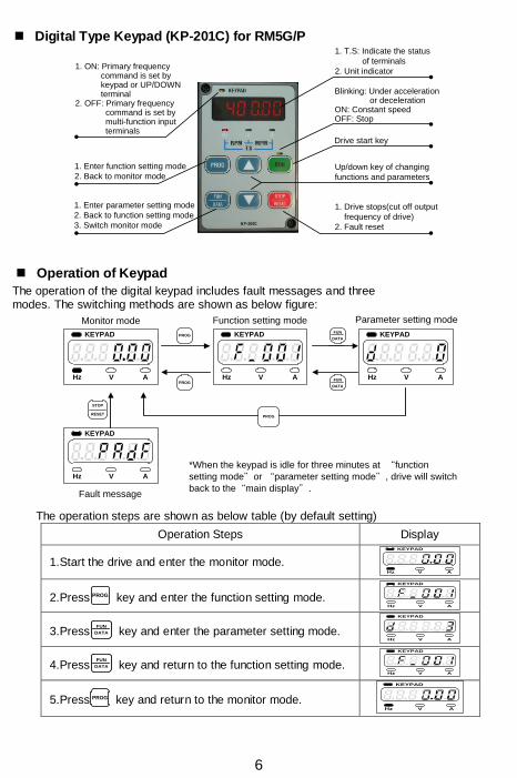
Digital Type Keypad (KP-201C) for RM5G/P
Operation of Keypad
1. T.S: Indicate the status
of terminals
2. Unit indicator
Blinking: Under acceleration or decelerationON: Constant speedOFF: Stop
Drive start key
Up/down key of changing
functions and parameters
1. Drive stops(cut off output
frequency of drive)
2. Fault reset
1. Enter parameter setting mode
2. Back to function setting mode
3. Switch monitor mode
1. Enter function setting mode
2. Back to monitor mode
1. ON: Primary frequency command is set by keypad or UP/DOWN terminal2. OFF: Primary frequency command is set by multi-function input terminals
The operation of the digital keypad includes fault messages and three modes. The switching methods are shown as below figure:
Monitor mode Function setting mode Parameter setting mode
Fault message
FUN
DATA
PROGFUN
DATA
STOP
RESET
PROG
PROG
KEYPAD
Hz V A
KEYPAD
Hz V A
KEYPAD
Hz V A
KEYPAD
Hz V A
*When the keypad is idle for three minutes at “function
setting mode”or “parameter setting mode”, drive will switch
back to the“main display”.
The operation steps are shown as below table (by default setting)
Operation Steps Display
1.Start the drive and enter the monitor mode.
KEYPAD
Hz V A
2.Press PROG key and enter the function setting mode.
KEYPAD
Hz V A
3.PressFUN
DATA key and enter the parameter setting mode.
KEYPAD
Hz V A
4.PressFUN
DATA key and return to the function setting mode.
KEYPAD
Hz V A
5.Press PROG key and return to the monitor mode.
KEYPAD
Hz V A

7
Description of Monitor Mode
There are eight displays can be selected in the monitor mode. Press FUN
DATA
to switch the display in accordance with below sequence under monitor mode. User can determine one of eight displays as the main display from function F_006 (Selection of Main Display). Please refer to the following illustrations:
Display 1
(Output Frequency)
Display 2
(Frequency Command)
Display 3
(Output Voltage)
Display 5
(Output Current)
Display 6(Motor Speed(RPM))
Monitor
Mode
Display 4
(DC Bus Voltage)
FUN
DATA
FUN
DATA
KEYPAD
Hz V A
KEYPAD
Hz V A
KEYPAD
Hz V A
KEYPAD
Hz V A
KEYPAD
Hz V A
FUN
DATA
FUN
DATA
KEYPAD
Hz V A
FUN
DATA
FUN
DATA
KEYPAD
Hz V A
KEYPAD
Hz V A
Display 7(Machine Speed(MPM))
Display 8
(Terminal Status)
FUN
DATA
FUN
DATA
Enter monitor mode
a. Select one of eight displays as the main display from function F_006 (Selection of Main Display).
b. Determine one of eight displays as the main display according to the application. When the parameter of function is completed without pressing key, the drive will automatically
switch back to the main display after 3 minute.

8
Parameter List
Func. Name Description Range of Setting
Unit Default
F_000 Drive Information
0: Software version1: Drive model number 2: Drive running hours 3: Drive supply power time 4: Software checksum code 5: Reserved
─ ─ ─
F_001 Start Command
Selection
Start command Rotation direction command
0~4 ─ 3
0: FWD or REV terminal FWD or REV terminal
1: FWD terminal REV terminal
2:
Keypad “RUN” key
FWD, REV terminal
3: Forward direction
4: Reverse direction
F_002
Primary Frequency Command Selection
0:Frequency command by analog signal via terminal. 1:Frequency command by keypad. 2: Motor speed (RPM) command by keypad. 3: Machine speed (MPM) command by keypad. 4: Frequency command by UP/DOWN terminal.
0~4 ─ 1
F_003 Selection of “STOP” Key
Validity
0: Start command by terminal, “STOP” key disabled. 1: Start command by terminal, “STOP” key enabled.
0,1 ─ 1
F_004 Frequency Command Selection
0: In the monitor mode, frequency command cannot be changed.
1: In the monitor mode, frequency command is changeable.
0,1 ─ 1
F_005
Selection of Frequency Command
Auto-Storing
0: In the monitor mode, frequency command auto-storing disable.
1: In the monitor mode, frequency command auto-storing after 3 minutes.
0,1 ─ 1
F_006 Selection of Main Display
Select 1 of 8 “monitor modes” as the main display. 1~8 ─ 1
F_007 Machine Speed
Ratio Set the ratio of machine speed. This function determines MPM display value.
0.00~ 500.00
0.01 20.00
F_008 Digits of Decimal Value (Machine
Speed)
Select the digits of decimal values displaying the machine speed.
0~3 ─ 0
F_009 Primary Speed
Jog speed command
Multi-speed level 3
command
Multi-speed level 2
command
Multi-speed level 1
command
0.00~ 400.00
0.01 Hz
50.00 (Note1)
OFF OFF OFF OFF 60.00 (Note2)
F_010 Preset Speed 1 OFF OFF OFF ON 10.00
F_011 Preset Speed 2 OFF OFF ON OFF 20.00
F_012 Preset Speed 3 OFF OFF ON ON 30.00
F_013 Preset Speed 4 OFF ON OFF OFF 0.00
F_014 Preset Speed 5 OFF ON OFF ON 0.00
F_015 Preset Speed 6 OFF ON ON OFF 0.00
F_016 Preset Speed 7 OFF ON ON ON 0.00
F_017 Jog Speed ON X X X 6.00
F_018 Reference
Frequency of Accel/Decel Time
The frequency corresponding to accel/decel time. 0.01~ 400.00
0.01 Hz
50.00 (Note1)
60.00 (Note2)
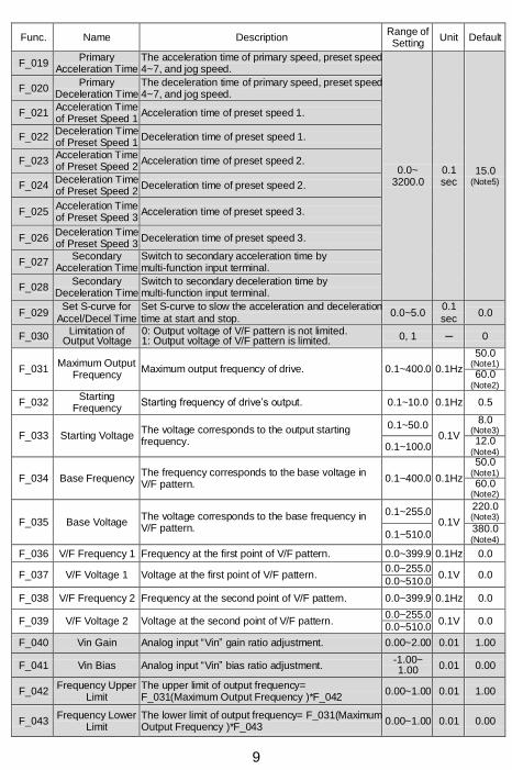
9
Func. Name Description Range of Setting
Unit Default
F_019 Primary
Acceleration Time The acceleration time of primary speed, preset speed 4~7, and jog speed.
0.0~ 3200.0
0.1 sec
15.0 (Note5)
F_020 Primary
Deceleration Time The deceleration time of primary speed, preset speed 4~7, and jog speed.
F_021 Acceleration Time of Preset Speed 1
Acceleration time of preset speed 1.
F_022 Deceleration Time of Preset Speed 1
Deceleration time of preset speed 1.
F_023 Acceleration Time of Preset Speed 2
Acceleration time of preset speed 2.
F_024 Deceleration Time of Preset Speed 2
Deceleration time of preset speed 2.
F_025 Acceleration Time of Preset Speed 3
Acceleration time of preset speed 3.
F_026 Deceleration Time of Preset Speed 3
Deceleration time of preset speed 3.
F_027 Secondary
Acceleration Time Switch to secondary acceleration time by multi-function input terminal.
F_028 Secondary
Deceleration Time Switch to secondary deceleration time by multi-function input terminal.
F_029 Set S-curve for
Accel/Decel Time Set S-curve to slow the acceleration and deceleration time at start and stop.
0.0~5.0 0.1 sec
0.0
F_030 Limitation of
Output Voltage 0: Output voltage of V/F pattern is not limited. 1: Output voltage of V/F pattern is limited. 0, 1 ─ 0
F_031 Maximum Output
Frequency Maximum output frequency of drive. 0.1~400.0 0.1Hz
50.0 (Note1)
60.0 (Note2)
F_032 Starting
Frequency Starting frequency of drive’s output. 0.1~10.0 0.1Hz 0.5
F_033 Starting Voltage The voltage corresponds to the output starting frequency.
0.1~50.0 0.1V
8.0 (Note3)
0.1~100.0 12.0
(Note4)
F_034 Base Frequency The frequency corresponds to the base voltage in V/F pattern.
0.1~400.0 0.1Hz
50.0 (Note1)
60.0 (Note2)
F_035 Base Voltage The voltage corresponds to the base frequency in V/F pattern.
0.1~255.0 0.1V
220.0 (Note3)
0.1~510.0 380.0 (Note4)
F_036 V/F Frequency 1 Frequency at the first point of V/F pattern. 0.0~399.9 0.1Hz 0.0
F_037 V/F Voltage 1 Voltage at the first point of V/F pattern. 0.0~255.0
0.1V 0.0 0.0~510.0
F_038 V/F Frequency 2 Frequency at the second point of V/F pattern. 0.0~399.9 0.1Hz 0.0
F_039 V/F Voltage 2 Voltage at the second point of V/F pattern. 0.0~255.0
0.1V 0.0 0.0~510.0
F_040 Vin Gain Analog input “Vin” gain ratio adjustment. 0.00~2.00 0.01 1.00
F_041 Vin Bias Analog input “Vin” bias ratio adjustment. -1.00~ 1.00 0.01 0.00
F_042 Frequency Upper
Limit The upper limit of output frequency= F_031(Maximum Output Frequency )*F_042
0.00~1.00 0.01 1.00
F_043 Frequency Lower
Limit The lower limit of output frequency= F_031(Maximum Output Frequency )*F_043
0.00~1.00 0.01 0.00
10
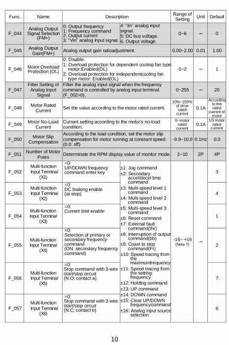
Func. Name Description Range of Setting
Unit Default
F_044 Analog Output
Signal Selection (FM+)
0: Output frequency 1: Frequency command 2: Output current 3: “Vin” analog input signal.
4: “Iin” analog input signal. 5: DC bus voltage. 6. Output voltage.
0~6 ─ 0
F_045 Analog Output
Gain(FM+) Analog output gain ratioadjustment. 0.00~2.00 0.01 1.00
F_046 Motor Overload Protection (OL)
0: Disable 1: Overload protection for dependent cooling fan type
motor:Enabled(OL) 2: Overload protection for independentcooling fan
type motor: Enabled(OL)
0~2 ─ 1
F_047 Filter Setting of Analog Input
Signal
Filter the analog input signal when the frequency command is controlled by analog input terminal. (F_002=0).
0~255 ─ 20
F_048 Motor Rated
Current Set the value according to the motor rated current.
10%~150%of drive rated
current
0.1A
According to the rated
current of motor
F_049 Motor No-Load
Current Current setting according to the motor’s no-load condition.
0~motor rated
current 0.1A
1/3 motor rated
current
F_050 Motor Slip
Compensation
According to the load condition, set the motor slip compensation for motor running at constant speed. (0.0: off)
-9.9~10.0 0.1Hz 0.0
F_051 Number of Motor
Poles Determinate the RPM display value of monitor mode. 2~10 2P 4P
F_052 Multi-function
Input Terminal (X1)
=0: UP/DOWN frequency command enter key
±1: Jog command
±2: Secondary accel/decel time command
±3: Multi-speed level 1 command
±4: Multi-speed level 2 command
±5: Multi-speed level 3 command
±6: Reset command
±7: External fault command(thr)
±8: Interruption of output command(bb)
±9: Coast to stop command(Fr)
±10: Speed tracing from the maximumfrequency
±11: Speed tracing from the setting frequency
±12: Holding command
±13: UP command
±14: DOWN command
±15: Clear UP/DOWN frequencycommand
±16: Analog input source selection
-16~ +16 (Note 7)
─
3
F_053 Multi-function
Input Terminal (X2)
=0: DC braking enable (at stop) 4
F_054 Multi-function Input Terminal
(X3)
=0: Current limit enable
1
F_055 Multi-function Input Terminal
(X4)
=0: Selection of primary or secondary frequency command (ON: secondary frequency command)
2
F_056 Multi-function
Input Terminal (X5)
=0: Stop command with 3-wire start/stop circuit (N.O; contact a) 7
F_057 Multi-function
Input Terminal (X6)
=0: Stop command with 3-wire start/stop circuit (N.C; contact b) 6

11
Func. Name Description Range of Setting
Unit Default
F_058
Multi-function
Output Terminal
(Y1)
0: Disable ±1: Operation command detection ±2: Constant speed detection ±3: Zero speed detection ±4: Frequency detection ±5: Overload detection(OLO) ±6: Stall prevention detection ±7: Low voltage detection(LE) ±8: Braking detection ±9: Restart after instantaneous power failure
detection ±10: Restart after error condition detection ±11: Error detection
-11 ~+11 (Note 7)
─
3
F_059
Multi-function
Output Terminal
(Y2)
2
F_060 Multi-function
Output Terminal (Ta1,Tb1)
11
F_061 Constant Speed Detection Range
Set the bandwidth of constant speed detection range. 0.0~10.0 0.1Hz 2.0
F_062 Frequency
Detection Range Set the bandwidth of frequency detection range. 0.0~10.0 0.1Hz 2.0
F_063 Frequency
Detection Level Set the frequency detection level of multi-function output terminal.
0.0~400.0 0.1Hz 0.0
F_064 Automatic Torque
Compensation Range
According to the load condition, adjust the output voltage of the V/F pattern. (0.0: off)
0.0~25.5 0.1 1.0
F_065 System Overload Detection (OLO)
0: Disable 1: Enable
0,1 ─ 0
F_066 System Overload
DetectingSelection 0: Detection during constant speedonly 1: Detection during operation only
0,1 ─ 0
F_067 Output Setting after System
Overload
0: Drive keeps operation when the overload is detected
1: Drive trips to protection when the overload isdetected
0,1 ─ 0
F_068 System Overload Detection Level
When the output current of drive is larger than the levelwith the duration of F_069, the drive will trip to protection.
30%~200% of drive rated
current 1% 160
F_069 System Overload Detection Time
When the output current of drive is larger than the level (F_068 * drive’s rated current) with the duration, the drive will trip to protection.
0.1~10.0 0.1 sec
0.1
F_070 Stall Prevention
Level at Acceleration
If stall is occurred during acceleration, the motor keeps running at constant speed. (200%: off)
30%~200% of drive rated
current
1% 170
F_071 Stall Prevention
Level at Constant Speed
While the stall is occurred during constant speed running condition, the prevention of stall is to decrease the speed of motor.(200%: off)
30%~200% of drive rated
current
1% 160
F_072
Acceleration Time Setting after Stall Prevention under Constant Speed
Set the acceleration time after stall prevention under the constant speed.
0.1~ 3200.0
0.1 sec
15.0 (Note5)
F_073
Deceleration Time Setting for Stall
Prevention under Constant Speed
Set the deceleration time at the stallprevention under the constant speed.
0.1~ 3200.0
0.1 sec
15.0 (Note5)
F_074 Stall Prevention
Setting at Deceleration
0: Disable 1: Enable
0, 1 ─ 1
F_075 DC Braking Level Set the current level of DC braking.
0~150% of drive rated
current 1% 50

12
Func. Name Description Range of Setting
Unit Default
F_076 Time of DC
Braking after Stop Set the time for DC braking after drive stopped. 0.0~20.0
0.1 sec
0.5
F_077 Time of DC
Braking before Start
Set the time for DC braking before drive started. 0.0~20.0 0.1 sec
0.0
F_078
Operation Selection at
Instantane- ous Power Failure
0: Drive cannot be restarted 1: Drive can be restarted 2: Ramp to stop 3: Drive will re-accelerate again during ramp to stop
interval, when the power is restored.
0~3 ─ 0
F_079 Voltage Level of Ramp to Stop by
Power Failure Set the voltage of power source for ramp to stop.
150.0~ 192.0
0.1V
175.0 (Note3)
300.0~ 384.0
320.0 (Note4)
F_080 Auto-restart Times
Setting of Error Trip
When the auto-restart times of error conditions (OC,OE,GF only) reach the setting value, the drive must be restarted manually. 0: disable
0~16 1 0
F_081 Switching Frequency
The setting value is higher and the motor noise is lower.
0~6 ─ 1 (Note6)
F_082 Stop Mode 0: Ramp to stop 1: Coast to stop 2: Coast to stop+ DC braking
0~2 ─ 0
F_083 Reverse
Prohibition 0: Reverse rotation allowed. 1: Reverse rotation NOT allowed.
0, 1 ─ 0
F_084 Jump Frequency 1 Avoid mechanical resonance point 1. 0.0~400.0 0.1Hz 0.0
F_085 Jump Frequency 2 Avoid mechanical resonance point 2. 0.0~400.0 0.1Hz 0.0
F_086 Jump Frequency 3 Avoid mechanical resonance point 3. 0.0~400.0 0.1Hz 0.0
F_087 Jump Frequency
Range Set the range of the jump frequency 1, 2, 3. 0.0~25.5 0.1Hz 0.0
F_088 The Current Level of Speed Tracing
When the current is higher than the “speed tracingcurrent level”, the output frequency will trace downward.
0~200%
of drive rated
current
1% 150
F_089 Delay Time before
Speed Tracing Set the output delay time before the speed tracing. 0.1~5.0 0.1
sec 0.5
F_090 The V/F Pattern of
Speed Tracing Set the percentage of V/F output voltage at the speed tracing.
0~100% 1% 100
F_091 Error Record Display the latest 5 error records. ─ ─ ─
F_092 Parameter Setting
Lock
0: Parameters are changeable. Maximum frequency cannot exceed 120.0Hz.
1: Parameters are locked. Maximum frequency cannot exceed 120.0Hz.
2: Parameters are changeable. Maximum frequency can exceed 120.0Hz.
3: Parameters are locked. Maximum frequency can exceed 120.0Hz.
0~3 ─ 0
F_093 Automatic Voltage Regulation (AVR)
0: Disable 1: Enable
0,1 ─ 1
F_094 Drive Overload
(OL1)
0: Disable 1: Thermal protection 2: Current limit overload protection 3: Both 1 and 2 enable
0~3 ─ 3
F_095 Power Source The value of setting according to the actual power source.
190.0~ 240.0
0.1V
220.0 (Note3)
340.0~ 480.0
380.0 (Note4)

13
Func. Name Description Range of Setting
Unit Default
F_096 Holding Frequency The drive accelerates to the holding frequency and running at constant speed.
0.0~400.0 0.1Hz 0.5
F_097 Holding Time
Interval The drive runs at holding frequency by constant speed and running the time interval.
0.0~25.5 0.1 sec
0.0
F_098 Grounding Fault Protection (GF)
0: Disable 1: Enable(GF)
0, 1 ─ 1
F_099 External Indicator
1 Select the monitor mode of external indicator 1 0: Disable
0~8 ─ 1
F_100 External Indicator
2 Select the monitor mode of external indicator 2 0: Disable
0~8 ─ 2
F_101 External Indicator
3 Select the monitor mode of external indicator 3 0: Disable
0~8 ─ 3
F_102 V/F Pattern Selection
0:Linear. 1: Energy-saving mode (auto-adjust V/F pattern
according to the load condition). 2: Square curve. 3: 1.7
th power curve.
4: 1.5th power curve.
0~4 ─ 0
F_103
Subtracted Frequency of
Deceleration at Power Failure
When the power failure, drive will reduce the frequency level before ramp to stop. F_078 Operation Selection at Instantaneous Power Failure =2 or 3
0.0~20.0 0.1Hz 3.0
F_104 Deceleration Time 1 of Ramp to Stop by Power Failure
Set a deceleration time down to the turning frequency set in F_106.
0.0~ 3200.0
0.1 sec
15.0 (Note5)
F_105 Deceleration Time 2 of Ramp to Stop by Power Failure
Set a deceleration slope below the frequency set in F_106
0.0~ 3200.0
0.1 sec
15.0 (Note5)
F_106 Turning Frequency of Ramp to Stop
Set the turning frequency level of ramp to stopwhen the deceleration time is switched from F_104 setting value to F_105setting value.
0.0~400.0 0.1Hz 0.0
F_107 Analog Frequency
Dead Band
When the noise of analog input signal is large,appropriately increase the dead band to stabilize the frequency command. But adjusting this function will reduce the tuning linearity of input signal.
0.00~2.55 0.01 Hz
0.00
F_108 Digital Input
Response Time When the pulse width of digital signal is lower than setting time, the signal disabled.
5~16 1ms 10
F_110 ADJ4 Function
Selection Set the function of ADJ4switch of KP-202 keypad. 0~49 ─ 1
F_111 ADJ5 Function
Selection Set the function of ADJ5switch of KP-202 keypad. 0~49 ─ 20
F_112 ADJ6 Function
Selection Set the function of ADJ6switch of KP-202 keypad. 0~49 ─ 17
F_113 DIP1 Function
Selection Set the function of DIP1switch of KP-202 keypad. 0~15 ─ 8
F_114 DIP2 Function
Selection Set the function of DIP2switch of KP-202 keypad. 0~15 ─ 5
F_115 DIP3 Function
Selection Set the function of DIP3switch of KP-202 keypad. 0~15 ─ 3
F_116 DIP4 Function
Selection Set the function of DIP4switch of KP-202 keypad. 0~15 ─ 1
F_117 Pot Knob of
KP-202 keypad Function Selection
Set the function of pot knob of KP-202 keypad. 0~49 ─ 0

14
Func. Name Description Range of Setting
Unit Default
F_118 UP/DOWN
Memory Selection
0: Clear the UP/DOWN frequency command when power failure.
1: Save the UP/DOWN frequency command at F_121 when power failure.
0, 1 ─ 0
F_119 UP/DOWN Frequency Resolution
0: 1~8:
9: 10~250:
0.01Hz x0.05Hz 0.5Hz x0.1Hz
0~250 ─ 0
F_120 UP/DOWN Trigger
Mode
1~5: Cntinuousaccel./decel. when the terminal is activated with the duration (1 ~ 5 sec). 6: Edge trigger
1~6 ─ 1
F_121 UP/DOWN Frequency Adjustment
Adjust UP/DOWN frequency by KP-201C keypad. 0.00~ 400.00
0.01 Hz
0.00
F_122
Secondary Frequency
CommandSelection
0:Frequency command by analog signal via terminal. 1: Frequency command by keypad. 2: Frequency command by UP/DOWN terminal.
0~2 ─ 0
F_123 Analog
InputSelection
0: Vin+Iin 1: Vin-Iin 2: Iin-Vin 3: Vin or Iin
(switch by multi-function input terminal X1 ~ X6).
0~3 ─ 0
F_124 Analog Input
Selection (Vin)
0: Analog input gain. 1: Frequency command. 2: Current limit level. 3: Analog input (Vin) can adjust output voltage of V/F pattern
0~3 ─ 1
F_125 Analog Input
Selection (Iin)
0: Analog input gain. 1: Frequency command. 2: Current limit level. 3: Analog input (Iin) can adjust output voltage of V/F pattern
0~3 ─ 1
F_126 Iin Range Selection
0: 4~20mA (2~10V). 1: 0~20mA (0~10V).
0,1 ─ 0
F_127 Analog Input
Gain(Iin) The gain ratio of analog input terminal Iin. 0.00~2.00 0.01 1.00
F_128 Analog Input
Bias(Iin) The bias ratio of analog input terminal Iin.
-1.00~ 1.00
0.01 0.00
F_129 Analog Output
Signal Selection (AM+)
0: Output frequency. 1: Frequency command. 2: Output current. 3: Vin frequency command 4: Iin frequency command. 5: DC bus voltage 6: Output voltaga
0~6 ─ 2
F_130 Analog Output
Gain(AM+) AM+ analog output adjustment ratio. 0.00~2.00 0.01 1.00
F_131 Multi-function
Output Terminal (Ta2/Tc2)
The way of settings are same as multi-function output terminals setting.(F_058 ~ F_060)
-11~+11 (Note 7)
─ 1
F_132 DC Braking
Frequencyat Stop Active frequency level of DC braking at stop. 0.1~60.0 0.1Hz 0.5
F_133 Current Limit Level Monitor the setting value of current limit level percentage.
─ ─ ─

15
Func. Name Description Range of Setting
Unit Default
F_134 Default Setting
0: Disable
─ ─ ─
CLF: Clear fault records
dEF60: Restore the default value of drive for 60Hz.
dEF50: Restore the default value of drive for 50Hz.
SAv: Save the setting value.
rES: Restore the setting value.
rd_EE: Read the parameters from drive to digital keypad
Wr_EE: Write the parameters from digital keypad to drive
F_135 Parameter Display
Selection of Parameter Lock
1: Paramerter cannot be changed after F0.18 locked, but it can display the setting value. 2: Paramerter cannot be changed after F0.18 locked, but it cannot display the setting value.
0~1 ─ 0
F_136 Parameter Lock
Password Setting Setting the password of parameter lock. 0~9999 1 0
F_137 Parameter Lock Decoding Setting
Decording the password of parameter lock. 0~9999 1 ─
F_154 Default Setting
0: Disable
─ ─ 0
CLF: Clear fault records
dEF60: Restore the default value of drive for 60Hz.
dEF50: Restore the default value of drive for 50Hz.
SAv: Save the setting value.
rES: Restore the setting value.
rd_EE: Read the parameters from drive to digital keypad(KP-201C)
Wr_EE: Wr_EE: Write the parameters from digital keypad(KP-201C) to drive
The color as means the functions can be set during operation.
Note: 1. Default value of 50Hz. 2. Default value of 60Hz. 3. Specification of 200V series. 4. Specification of 400V series. 5. 0.5 ~ 5HP: 5sec
7.5 ~ 30HP: 15sec 40HP above: 30sec
6. RM5G series: When switching frequency setting exceeds 4, the drive must be de-rating or selecting higher capacity.
RM5P series: When switching frequency setting exceeds 2, the drive must be de-rating or selecting higher capacity.
7.+: Represents a contact (N.O)
-: Represents b contact (N.C)

16
Error Trip Messages of Drive
Display Description Display Description
(EEr) KEYPAD
Hz V A
EEPROM error
(OLO) KEYPAD
Hz V A
System overload
(AdEr) KEYPAD
Hz V A
A/D converter error
(thr) KEYPAD
Hz V A
External fault
(SC) KEYPAD
Hz V A
Fuse open
(PAdF) KEYPAD
Hz V A
Keypad interruption during copy
(LE1) KEYPAD
Hz V A
Under voltage during operation
(OH) KEYPAD
Hz V A
Drive overheating
(OC) KEYPAD
Hz V A
Drive over current
(OL) KEYPAD
Hz V A
Motor overload
(GF) KEYPAD
Hz V A
Grounding fault
(OL1) KEYPAD
Hz V A
Drive overload
(OE) KEYPAD
Hz V A
Over voltage
Warning Messages of Drive
Display Description Display Description
(LE) KEYPAD
Hz V A
Power source under voltage
(PrEr) KEYPAD
Hz V A
Software fault
(bb) KEYPAD
Hz V A
Drive output interruption
(Err_00) KEYPAD
Hz V A (Err_01)
KEYPAD
Hz V A
Err_00: Keypad cable trip.(beforeconnecting) Err_01: Keypad cable trip.(connected)
(Fr) KEYPAD
Hz V A
Coast to stop
(dtF) KEYPAD
Hz V A
Direction command error
(db) KEYPAD
Hz V A
Over voltage at stop
(Wr_F) KEYPAD
Hz V A
Different software version inter-copy