road accident emergency response system
TRANSCRIPT
INTERSTATE COUNCIL
ON STANDARDIZATION, METROLOGY AND CERTIFICATION (ISC)
I N T E R S T A T E S T A N D A R D
GOST 33470-2015
Global navigation satellite system
ROAD ACCIDENT EMERGENCY RESPONSE SYSTEM
Test methods for wireless communication modules
of in-vehicle emergency call device/system
Official Edition English Version Approved by Interstandard
Moscow
Standartinform 2017
ГОСТ 33470-2015
II
Foreword
The purposes, main principles and basic order of work on interstate standardization are established
by GOST 1.0-2015 "Interstate system for standardization. Basic principles" and GOST 1.2-2015 "Interstate System for Standardization. Interstate standards. Rules for development, taking over, renovation and cancellation"
Details 1 DEVELOPED by Non-Commercial Partnership "For Promotion of Navigation Technologies
Development and Application" and Joint Stock Company "Research and Technical Centre of Advanced Navigation Technologies" "Internavigation" (JSC "Internavigation RTC")
2 INTRODUCED by Federal Agency on Technical Regulating and Metrology 3 ADOPTED by Interstate council for standardization, metrology and certification by means of
correspondence (protocol No. 82-П, dated 12.11.2015) Votes in favour:
Short name of the country according to IC
(ISO 3166) 004—97
Country code according to IC
(ISO 3166) 004—97 Abbreviated name of national standards body
Armenia AM Ministry of Economics of Republic of Armenia Belarus BY Gosstandart of Republic of Belarus Kazakhstan KZ Gosstandart of Republic of Kazakhstan Kyrgyzstan KG Kyrgyzstandart Russian Federation RU Rosstandart Tajikistan TJ Tajikstandart
4 Interstate Standard GOST 33470-2015 is introduced as a national standard of the Russian Federation by Order No. 2059-ст, dated 21.12.2016, of Federal Agency on Technical Regulating and Metrology from 01.01.2017.
5 This Standard developed on based GOST R 55533-2013* 6 INTRODUCED FOR THE FIRST TIME The information on the amendments to this Standard is published in the annually issued information
index "National standards", and the text of the amendments and corrections is published in the monthly issued information indices "National standards". In case of revision (replacement) or cancellation of this Standard the appropriate notice will be published in the monthly issued information index "National standards". The appropriate information, notice and texts are also placed in the general-use information system — on official site of Federal Agency on Technical Regulating and Metrology in the Internet (www.gost.ru) _________________
National standard GOST R 55533-2013 is withdrawn from 01.06.2017 by Order No. 2059-ст, dated 21.12.2016, of Federal Agency on Technical Regulating.
© Standartinform, 2017
This Standard may not be reproduced, in full or in part, reprinted or distributed as an official publication without the permission of Federal Agency on Technical Regulating and Metrology
ГОСТ 33470-2015
III
Contents
1 Scope ............................................................................................................................................................. 12 Normative references .................................................................................................................................... 13 Terms and definitions ................................................................................................................................... 24 Abbreviations ................................................................................................................................................ 35 General .......................................................................................................................................................... 46 Test methods of in-vehicle emergency call device/system with respect to implementation of GSM
modem functions ......................................................................................................................................... 57 Test methods of in-vehicle emergency call device/system with respect to implementation of UMTS
modem functions ......................................................................................................................................... 168 Test methods of in-vehicle emergency call device/system with respect to implementation of in-band
modem functions ......................................................................................................................................... 379 Checking feasibility of data update on non-removable personal universal multi-profile subscriber
identity card over wireless mobile communication networks ..................................................................... 47Appendix A (mandatory) Requirements for parameters and functional properties of GSM modems
used in 900/1800 MHz frequency bands ...................................................................................... 49Appendix B (mandatory) Requirements for parameters and functional properties of UMTS modems with
duplex frequency separation and frequency-code separation in 900 MHz frequency band ........ 56Appendix C (mandatory) Requirements for parameters and functional properties of UMTS modems with
duplex frequency separation and frequency-code separation in 2000 MHz frequency band ...... 62Appendix D (mandatory) Format of Act of Sampling for tests of in-vehicle emergency call device/system . 67Appendix E (mandatory) Structural flowcharts of test beds and connections for tests of in-vehicle
emergency call device/system in regard to implementation of UMTS modem functions ........... 68Appendix F (mandatory) Structural flowcharts of test beds and connections for tests of in-vehicle
emergency call device/system as regards implementation of in-band modem functions ............ 70Appendix G (recommended) Test methods of in-vehicle emergency call device/system for check of
possible data update on non-removable personal universal multi-profile subscriber identity card over wireless mobile communication networks .................................................................. 74
Bibliography .................................................................................................................................................... 75
ГОСТ 33470-2015
1
I N T E R S T A T E S T A N D A R D
Global navigation satellite system
ROAD ACCIDENT EMERGENCY RESPONSE SYSTEM
Test methods for wireless communication modules of in-vehicle emergency call device/system
Date of Introduction — 2017—01—01
1 Scope This Standard applies to in-vehicle emergency call devices and systems intended for installation on
vehicles of Categories M and N in accordance with the requirements of [1]. The Standard sets out the requirements for the parameters of wireless communication modules (GSM
modem, UMTS modem and in-band modem) included in the in-vehicle emergency call device (system) and defines the test methods that shall be used for conformity assurance to the requirements of [1] and GOST 33464 in part of data exchange processes taking place in GSM 900/1800 and UMTS 900/2000 wireless communication networks.
2 Normative references The following interstate standards are referred to in this Standard: GOST 12.1.019-79 Occupational safety standards system. Electrical safety. General requirements
and nomenclature of kinds of protection GOST 12.1.030-81 Occupational safety standards system. Electric safety. Protective conductive
earth, neutralling GOST 12.3.019-80 Occupational safety standards system. Electrical tests and measurements.
General safety requirements GOST 18321-73 Statistical quality control. Item random sampling methods GOST 24375-80 Radio communication. Terms and definitions GOST 33464-2015 Global navigation satellite system. Road accident emergency response system.
In-vehicle emergency call device/system. General technical requirements N o t e — When using this standard it is expedient to check the validation of the reference standards in the
general-use information system — on official site of Federal Agency on Technical regulating and Metrology in Internet or according to the annual information index "National standards" which is published as of January, 1st, of current year, and according to releases of monthly issued information index "National standards" in the current year. If a reference standard which the dated reference is provided to is replaced, it is recommended to use a version of this standard with the above specified year of approval (acceptance). If after the approval of this standard an amendment is inserted in a reference standard which the dated reference is provided to, and this amendment regards the provision referred to, it is recommended to apply this provision without regard to this amendment. If a reference standard is cancelled without a replacement, it is recommended to apply the provision which refers to it to a part which does not engage this reference. Official Edition
ГОСТ 33470-2015
2
3 Terms and definitions The terms defined in GOST 24375 as well as the following terms with their respective definitions are
used for the purposes of this Standard: 3.1 frame: Time interval equal to 20 ms corresponding to a single AMR or FR speech frame which
contains 160 time slices at a sampling rate of 8 kHz.
N o t e — The duration of a single time slice is taken equal to 125 μs.
3.2 minimum set of data; (MSD): Set of data transmitted by the in-vehicle emergency call system/device in the case of a road accident, including: location and movement parameters of the affected vehicle, accident time, vehicle VIN-code and other information necessary for emergency response.
3.3 GSM/UMTS module (modem): Transmit-receive device that belongs to a GSM and/or UMTS wireless mobile communication system, has no controls and display, is controlled using a special-purpose controller, and is intended for operation in devices or systems employing GSM and/or UMTS wireless mobile communication networks for the purpose of voice communication and data exchange.
3.4 operator of Road Accident Emergency Response System (System Operator): Legal entity carrying out the activities related to operation of the System, in particular, processing of data stored in its database.
3.5 in-vehicle emergency call system; IVS: System supporting the functions of an in-vehicle emergency call device and providing for automatic transmission of vehicle data messages when a road accident or an accident of other kind occurs.
N o t e s 1 In addition, an in-vehicle emergency call system may be used for manual transmission of vehicle data
messages in the case of road accidents or accidents of other type. 2 Categories of vehicles that shall be equipped with in-vehicle emergency call systems are specified in [1].
3.6 Road Accident Emergency Response System: Automated geographically distributed Federal and State Information System that uses the signals of the GLONASS Global Navigation Satellite System and of other active GNSS to provide for prompt collection of data related to road accidents or other emergencies on motor roads as well as for processing, storage and transmission of such data to emergency services, and to enable access to the said data for the concerned governmental or local authorities, officials, legal and natural persons.
N o t e — The Road Accident Emergency Response System is called "ERA-RB" in the Republic of Belarus, "EVAK" in the Republic of Kazakhstan, and "ERA-GLONASS" in the Russian Federation. These systems are analogous to the European eCall System currently in development, and are harmonised with it in regard to the main functional features (the use of in-band modem as the main data transmission tool, unified content and format of mandatory data transmitted in the MSD for road accidents, uniform procedures for initiation and termination of duplex voice connection with the persons in the vehicle cabin, etc.).
3.7 in-band modem: Modem that enables data transmission within the scope of the established voice connection.
3.8 in-vehicle emergency call device; IVD: Device used for measurement and evaluation of vehicle coordinates, speed and direction of movement based on the signals from at least two active Global Navigation Satellite Systems, for manual transmission of vehicle data messages when a road accident or an accident of other kind occurs, and for duplex voice communication with emergency services over wireless mobile communication networks.
N o t e s 1 In addition, an in-vehicle emergency call device may be used for automatic transmission of vehicle data
messages in the case of road accidents or accidents of other type. The types of road accidents detected automatically and the time frames for implementation of the function for
automatic transmission of vehicle data messages in the device are established in [1]. 2 Categories of vehicles that shall be equipped with in-vehicle emergency call devices are specified in [1].

ГОСТ 33470-2015
3
4 Abbreviations The following abbreviations are used for the purposes of this Standard:
ACK/NACK — Acknowledgment/No Acknowledgment (as regards the reception of data blocks over a HS-DPCCH);
AMR — Adaptive Multi Rate (voice codec based on the standard of adaptive encoding with a variable bitrate of sound files and intended for signal compression in the speech frequency range);
BER — Bit Error Rate; C/I ratio — ratio of the signal power at a carrier frequency to the power of inter-channel interferences; CPICH — Common Pilot Channel; DPCCH — Dedicated Physical Control Channel; DPCH — Dedicated Physical Channel; DPDCH — Dedicated Physical Data Channel; EDGE — Enhanced Data rates for GSM Evolution; EVM — Error Vector Magnitude; FoM — Figure of Merit; FR — speech codec based on the digital standard of speech encoding at a 13 kbit/s codec bitrate; GPRS — General Packet Radio Service; GSM — Global System for Mobile communications; HSCSD — High Speed Circuit Switched Data; HSDPA — High Speed Downlink Packet Access; HS-DPCCH — High Speed Dedicated Physical Control Channel; HS-PDSCH — High Speed Physical Downlink Shared Channel; HS-SCCH — High Speed Secondary Control Channel; HTTPs — HTTP extension supporting encryption; ICCID — unique serial number of SIM (USIM)-KapTbi; IMEI — International Mobile Station Equipment Identity; IMSI — International Mobile Subscriber Identity associated with each user of GSM, UMTS or
CDMA mobile communications; Ior — power spectral density of a signal received downstream at the antenna connector of the
subscriber terminal; ISDN — Integrated Services Digital Network; IVDS — In-Vehicle Emergency Call Device/System; IVDS-GSM — IVDS as a test item implementing the GSM modem functionality; IVDS-modem — IVDS as a test item implementing the in-band modem functionality; IVDS-UMTS — IVDS as a test item implementing the UMTS modem functionality; MNO — Mobile Network Operator; OCNS — Orthogonal Code Noise Signal (applied for network loading simulation); OTA — Over the Air (software update mechanism); PC — Personal Computer; PCM — Pulse-Code Modulation (or Modulator); P-CPICH — Primary Common Pilot Channel; PICH — Pilot Channel; PRACH — Physical Random Access Channel; PSTN — Public Switched Telephone Network; P-CCPCH — Primary Common Control Physical Channel; Qqualmin — Minimum permitted quality rating of received signals; Qrxlevmin — Minimum permitted level rating of received signals;

ГОСТ 33470-2015
4
RACH — Random Access Channel; REF Ior — Reference Ior (reference power spectral density of a signal received downstream at the
antenna connector); REFSENS — Reference Sensitivity; RF — Radio Frequency; RSCP — Received Signal Code Power; RX — Receiver; S-CCPCH — Secondary Common Control Physical Channel; SCH — Synchronisation Channel consisting of primary and secondary synchronisation channels; SIM — Subscriber Identity Module; SIM-card; SNR — Signal-to-Noise Ratio; TFCI — Transport Format Combination Indicator; TL — Testing Laboratory; TPC — Transmit Power Control; TX — Transmitter; UMTS — Universal Mobile Telecommunications System; USB — Universal Serial Bus; USIM/UICC — SIM-card for UMTS networks/Universal Integrated Circuit Card.
5 General 5.1 The conformity of wireless communication modules (GSM modem, UMTS modem and in-band
modem) to the requirements stated in Appendices A, B and C of GOST 33464 and in [1], [2], [3], and [4] shall be verified within the scope of the tests for an in-vehicle emergency call device/system.
5.2 The test methods detailed in Sections 6, 7 and 8 may be used for obligatory conformity assurance of an IVSD (in regard to functionality of communication modules included in it) in the forms of conformity assurance that are provided for in the National (State) legislation pertaining to communication, and adopted in the ensuing regulatory legal acts.
5.3 IVDS tests shall take place in testing laboratories (centres) accredited in accordance with the procedure established in the legislations of CIS member states as well as in other regulatory legal acts adopted in virtue of the said legislations.
5.4 The test results are included in a test and measurement report where the following is specified: a) designation, location, telephone, fax and e-mail of the testing laboratory (centre); b) identification of the test item; c) test conditions; d) description of test and measurement techniques with a reference to a normative document; e) testing equipment and measuring instruments used in tests; f) list of sections (clauses and subsections) that contain the requirements included in the conformity
assessment checklist, and the results of conformity assessment for each particular requirement; g) decision as to whether the test item meets the stated requirements; h) title, name and signature of the person who conducted the tests and measurements; i) title, name and signature of the head of the testing laboratory (centre), to be affixed with the seal of
the laboratory (centre); j) date of tests and measurements, issue date, and report registration number.
ГОСТ 33470-2015
5
5.5 In those inspections as per Sections 6—8 that provide for IVDS registration in wireless mobile
communication networks, the first step shall be the IVDS switching to Emergency Call mode, e.g., by pressing the "Emergency call" button or by call initiation using the System Simulator. All subsequent tests (inspections) shall proceed as long as the IVDS remains registered in the network after the emergency call.
6 Test methods of in-vehicle emergency call device/system with respect to
implementation of GSM modem functions 6.1 Test item
6.1.1 The test item shall be an IVDS-GSM sample in part of IVDS hardware/software solutions implementing the functionality of the wireless communication module that is included in the IVDS and rated for operation in accordance with the GSM 900/1800 standards.
6.1.2 Samples submitted to tests shall be selected by an authorised representative of the testing laboratory (certification body) from a batch of finished products that has been accepted by the manufacturer's QC. Based on the results of sampling, an Act shall be compiled in the form specified in Appendix D.
6.2 Purpose of tests
6.2.1 The tests are aimed at the verification of IVDS-GSM conformity to the requirements established in [1], GOST 33464 (subsection 8.3), and Appendix A.
6.3 Scope of tests
6.3.1 Three IVDS-GSM samples shall be submitted to tests after their sampling in accordance with 6.2, equipped and completed as per GOST 33464 (sections 5 and 21, respectively).
Where justified, the number of samples may be changed as agreed with the testing laboratory.
N o t e — As agreed with the testing laboratory, the tests of IVDS-GSM samples with a built-in antenna may be carried out for the samples with a special remote RF process connector. Given this, the built-in antenna shall be decoupled.
6.3.2 During the IVDS-GSM tests, the conformity is checked against the requirements established for:
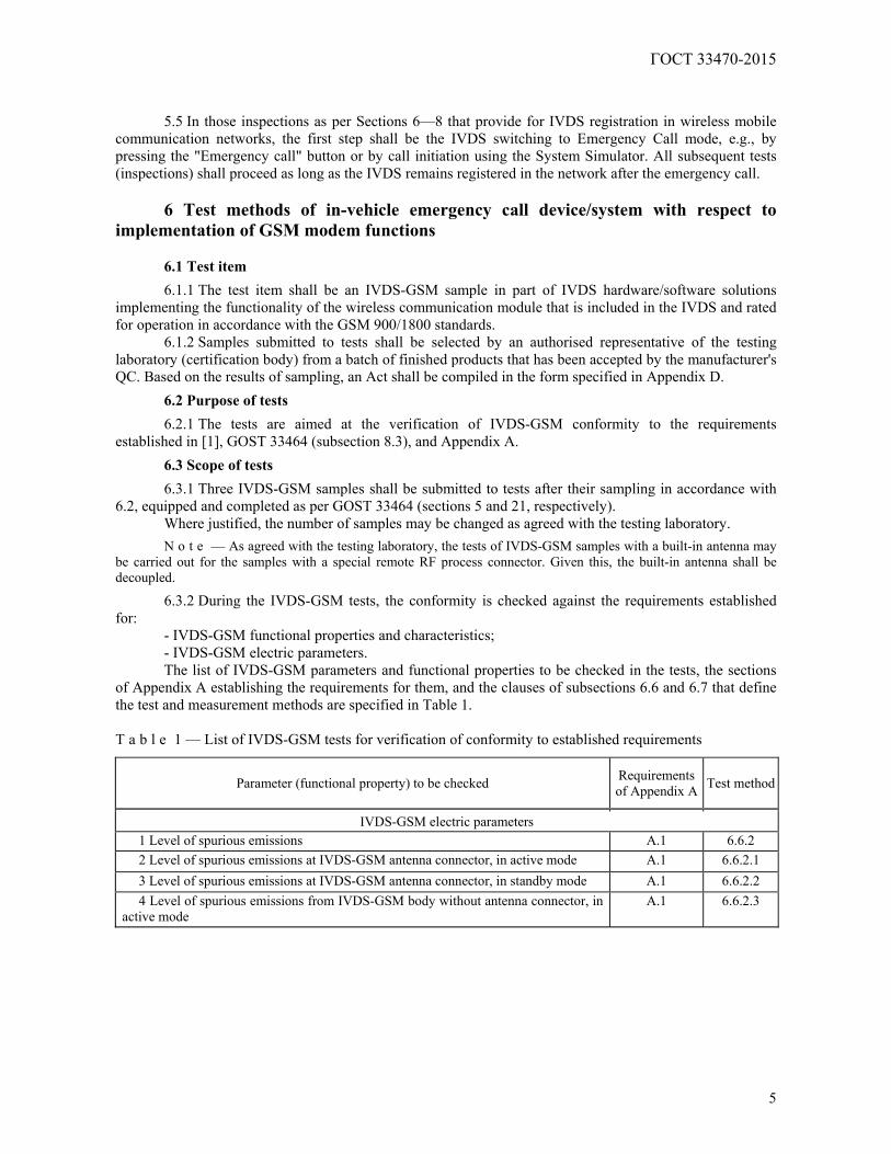
- IVDS-GSM functional properties and characteristics; - IVDS-GSM electric parameters. The list of IVDS-GSM parameters and functional properties to be checked in the tests, the sections
of Appendix A establishing the requirements for them, and the clauses of subsections 6.6 and 6.7 that define the test and measurement methods are specified in Table 1. T a b l e 1 — List of IVDS-GSM tests for verification of conformity to established requirements
Parameter (functional property) to be checked Requirements of Appendix A Test method
IVDS-GSM electric parameters 1 Level of spurious emissions A.1 6.6.2 2 Level of spurious emissions at IVDS-GSM antenna connector, in active mode A.1 6.6.2.1 3 Level of spurious emissions at IVDS-GSM antenna connector, in standby mode A.1 6.6.2.2 4 Level of spurious emissions from IVDS-GSM body without antenna connector, in
active mode A.1 6.6.2.3
ГОСТ 33470-2015
6
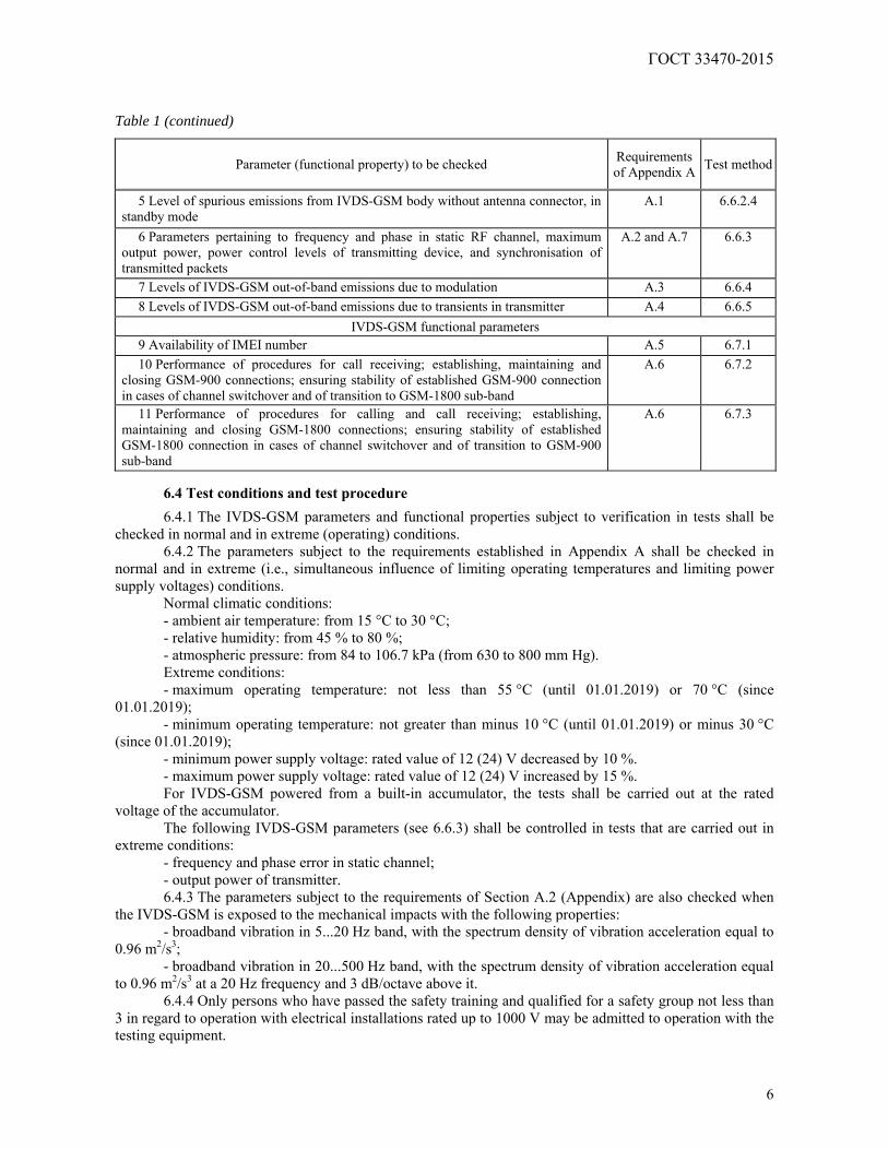
Table 1 (continued)
Parameter (functional property) to be checked Requirements of Appendix A Test method
5 Level of spurious emissions from IVDS-GSM body without antenna connector, in standby mode
A.1 6.6.2.4
6 Parameters pertaining to frequency and phase in static RF channel, maximum output power, power control levels of transmitting device, and synchronisation of transmitted packets
A.2 and A.7 6.6.3
7 Levels of IVDS-GSM out-of-band emissions due to modulation A.3 6.6.4 8 Levels of IVDS-GSM out-of-band emissions due to transients in transmitter A.4 6.6.5
IVDS-GSM functional parameters 9 Availability of IMEI number A.5 6.7.1 10 Performance of procedures for call receiving; establishing, maintaining and
closing GSM-900 connections; ensuring stability of established GSM-900 connection in cases of channel switchover and of transition to GSM-1800 sub-band
A.6 6.7.2
11 Performance of procedures for calling and call receiving; establishing, maintaining and closing GSM-1800 connections; ensuring stability of established GSM-1800 connection in cases of channel switchover and of transition to GSM-900 sub-band
A.6 6.7.3
6.4 Test conditions and test procedure
6.4.1 The IVDS-GSM parameters and functional properties subject to verification in tests shall be checked in normal and in extreme (operating) conditions.
6.4.2 The parameters subject to the requirements established in Appendix A shall be checked in normal and in extreme (i.e., simultaneous influence of limiting operating temperatures and limiting power supply voltages) conditions.
Normal climatic conditions: - ambient air temperature: from 15 °C to 30 °C; - relative humidity: from 45 % to 80 %; - atmospheric pressure: from 84 to 106.7 kPa (from 630 to 800 mm Hg). Extreme conditions: - maximum operating temperature: not less than 55 °C (until 01.01.2019) or 70 °C (since
01.01.2019); - minimum operating temperature: not greater than minus 10 °C (until 01.01.2019) or minus 30 °C
(since 01.01.2019); - minimum power supply voltage: rated value of 12 (24) V decreased by 10 %. - maximum power supply voltage: rated value of 12 (24) V increased by 15 %. For IVDS-GSM powered from a built-in accumulator, the tests shall be carried out at the rated
voltage of the accumulator. The following IVDS-GSM parameters (see 6.6.3) shall be controlled in tests that are carried out in
extreme conditions: - frequency and phase error in static channel; - output power of transmitter. 6.4.3 The parameters subject to the requirements of Section A.2 (Appendix) are also checked when
the IVDS-GSM is exposed to the mechanical impacts with the following properties: - broadband vibration in 5...20 Hz band, with the spectrum density of vibration acceleration equal to
0.96 m2/s3; - broadband vibration in 20...500 Hz band, with the spectrum density of vibration acceleration equal
to 0.96 m2/s3 at a 20 Hz frequency and 3 dB/octave above it. 6.4.4 Only persons who have passed the safety training and qualified for a safety group not less than
3 in regard to operation with electrical installations rated up to 1000 V may be admitted to operation with the testing equipment.
ГОСТ 33470-2015
7
6.4.5 In preparation to tests, the safety (electrical safety, fire safety, etc.) activities as well as the ones
related to grounding, metal coating and electrical insulation specified in the documentation for measuring instruments shall be completed.
6.4.6 The following steps shall be taken prior to tests. 6.4.6.1 Turn on the GSM system simulator, and prepare it for operation in accordance with the
requirements of its operating documents. 6.4.6.2 Connect the IVDS-GSM sample under test to the power supply, and turn on the IVDS-GSM. 6.4.7 The safety requirements established in GOST 12.1.019, GOST 12.1.030 and GOST 12.3.019 as
well as the operating documents for measuring instruments and testing equipment shall be observed during the tests.
6.5 Requirements for testing equipment and measuring instruments used in tests
6.5.1 The system simulator of GSM-900/1800 mobile communication networks (hereinafter referred to as the "system simulator") shall meet the requirements of [5] (section A5.3, Appendix A5).
6.5.1.1 The system simulator shall provide for a standard RF GSM-900/1800 signal in all possible GSM-900/1800 frequency channels that is modulated by information, service, calling and control digital streams ensuring normal IVDS-GSM operation when applied to the IVDS-GSM sample in all test types.
6.5.1.2 The system simulator shall be capable of receiving an RF signal from the IVDS-GSM, measuring all signal parameters, analysing demodulated digital streams, evaluating the probability of errors in them, and identifying the IVDS-GSM response to the transmitted commands.
6.5.1.3 The system simulator shall include such functional units as spectrum analyser, protocol analyser and RF level meters.
6.5.1.4 The system simulator shall be controlled from the personal computer. 6.5.1.5 Each type of tests requires generation of a signal set that is sent to the IVDS-GSM, and a
reference signal set that is used for comparison with the signals received from the IVDS-GSM. All these signals shall be stored in memory of the hardware/software complex, and read by commands corresponding to the selected type of measurements.
6.5.1.6 The system simulator shall be of an approved type of measuring instruments, and shall be provided with a calibration certificate valid as of the date when the tests are performed.
6.5.1.7 The hardware and software parameters of the system simulator shall be suitable for connection to the RF I/O of the IVDS-GSM through its antenna interface.
The following operations shall be completed for automatic conformity check of parameters against the requirements specified in Appendix A:
1) transmission of commands and test digital data streams required for IVDS-GSM operation in test mode to the antenna interface of the IVDS-GSM under test in dedicated control and data channels;
2) reception of RF signal from the IVDS-GSM, assessment of signal parameters, analysis of demodulated digital streams, evaluation of possible errors in streams, and identification of IVDS-GSM response to the transmitted commands;
3) generation of a test signal set transmitted to the IVDS-GSM; 4) generation of a reference signal set for comparison with the signals received from the IVDS-GSM. 6.5.1.8 Connection between the system simulator and the IVDS-GSM under test is established using
the basic connection setup and loopback test procedure programmed in the system simulator. After the connection between the system simulator and the IVDS-GSM under test is established
following the requirements of 5.5, the system simulator display shall, in addition to any other data, indicate the IMEI of the IVDS-GSM under test and the identification parameters of the subscriber registered in the virtual cellular operator's network of the Road Accident Emergency Response System (IMSI and/or ICCID).
The values of IMEI, IMSI and ICCID shall conform to the ones indicated in the general description of the IVDS-GSM sample type. Upon that, the relevant IMSI and ICCID fields shall include the Operator's identification parameters of the Road Accident Emergency Response System.
ГОСТ 33470-2015
8
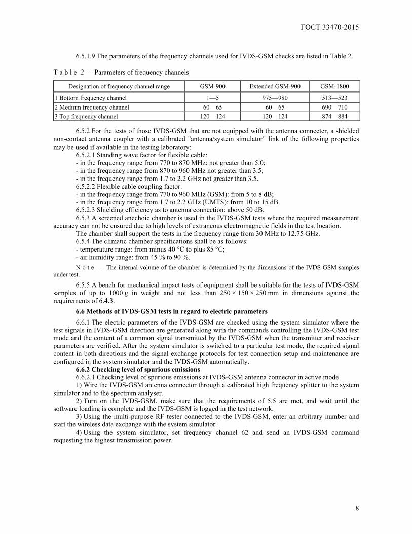
6.5.1.9 The parameters of the frequency channels used for IVDS-GSM checks are listed in Table 2. T a b l e 2 — Parameters of frequency channels
Designation of frequency channel range GSM-900 Extended GSM-900 GSM-1800
1 Bottom frequency channel 1—5 975—980 513—523 2 Medium frequency channel 60—65 60—65 690—710 3 Top frequency channel 120—124 120—124 874—884
6.5.2 For the tests of those IVDS-GSM that are not equipped with the antenna connecter, a shielded non-contact antenna coupler with a calibrated "antenna/system simulator" link of the following properties may be used if available in the testing laboratory:
6.5.2.1 Standing wave factor for flexible cable: - in the frequency range from 770 to 870 MHz: not greater than 5.0; - in the frequency range from 870 to 960 MHz not greater than 3.5; - in the frequency range from 1.7 to 2.2 GHz not greater than 3.5. 6.5.2.2 Flexible cable coupling factor: - in the frequency range from 770 to 960 MHz (GSM): from 5 to 8 dB; - in the frequency range from 1.7 to 2.2 GHz (UMTS): from 10 to 15 dB. 6.5.2.3 Shielding efficiency as to antenna connection: above 50 dB. 6.5.3 A screened anechoic chamber is used in the IVDS-GSM tests where the required measurement
accuracy can not be ensured due to high levels of extraneous electromagnetic fields in the test location. The chamber shall support the tests in the frequency range from 30 MHz to 12.75 GHz. 6.5.4 The climatic chamber specifications shall be as follows: - temperature range: from minus 40 °C to plus 85 °C; - air humidity range: from 45 % to 90 %.
N o t e — The internal volume of the chamber is determined by the dimensions of the IVDS-GSM samples under test.
6.5.5 A bench for mechanical impact tests of equipment shall be suitable for the tests of IVDS-GSM samples of up to 1000 g in weight and not less than 250 × 150 × 250 mm in dimensions against the requirements of 6.4.3.
6.6 Methods of IVDS-GSM tests in regard to electric parameters
6.6.1 The electric parameters of the IVDS-GSM are checked using the system simulator where the test signals in IVDS-GSM direction are generated along with the commands controlling the IVDS-GSM test mode and the content of a common signal transmitted by the IVDS-GSM when the transmitter and receiver parameters are verified. After the system simulator is switched to a particular test mode, the required signal content in both directions and the signal exchange protocols for test connection setup and maintenance are configured in the system simulator and the IVDS-GSM automatically.
6.6.2 Checking level of spurious emissions 6.6.2.1 Checking level of spurious emissions at IVDS-GSM antenna connector in active mode 1) Wire the IVDS-GSM antenna connector through a calibrated high frequency splitter to the system
simulator and to the spectrum analyser. 2) Turn on the IVDS-GSM, make sure that the requirements of 5.5 are met, and wait until the
software loading is complete and the IVDS-GSM is logged in the test network. 3) Using the multi-purpose RF tester connected to the IVDS-GSM, enter an arbitrary number and
start the wireless data exchange with the system simulator. 4) Using the system simulator, set frequency channel 62 and send an IVDS-GSM command
requesting the highest transmission power.
ГОСТ 33470-2015
9
5) If the IVDS-GSM is equipped with an auxiliary low-range receive/transmit device rated for 2.4 GHz, switch it to transmission at the highest power.
6) Using the spectrum analyser, measure the spurious emission levels with the IVDS-GSM in active mode for GSM-900 taking power level measurements for any discrete signal spectrum component at a 50 Ohm load, above a level that is 6 dB less than the ones indicated in Table A.1 (Appendix A).
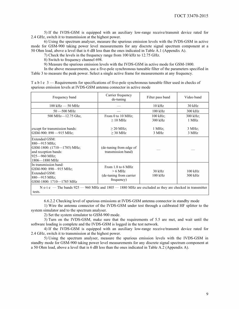
7) Check the levels in the frequency range from 100 kHz to 12.75 GHz. 8) Switch to frequency channel 698. 9) Measure the spurious emission levels with the IVDS-GSM in active mode for GSM-1800. In the above measurements, use a five-pole synchronous tuneable filter of the parameters specified in
Table 3 to measure the peak power. Select a single active frame for measurements at any frequency. T a b l e 3 — Requirements for specifications of five-pole synchronous tuneable filter used in checks of spurious emission levels at IVDS-GSM antenna connector in active mode
Frequency band Carrier frequency de-tuning Filter pass band Video band
100 kHz — 50 MHz — 10 kHz 30 kHz 50 —500 MHz — 100 kHz 300 kHz
500 MHz—12.75 Ghz, except for transmission bands: GSM-900: 890 —915 MHz;
From 0 to 10 MHz; ≥ 10 MHz
≥ 20 MHz; ≥ 30 MHz
100 kHz; 300 kHz
1 MHz; 3 MHz
300 kHz; 1 MHz
3 MHz; 3 MHz
Extended GSM: 880—915 MHz; GSM-1800: (1710—1785) MHz; and reception bands: 925—960 MHz; 1806—1880 MHz
(de-tuning from edge of transmission band) — —
In transmission band: GSM-900: 890—915 MHz; Extended GSM: 880—915 MHz; GSM-1800: 1710—1785 MHz
From 1.8 to 6 MHz > 6 MHz
(de-tuning from carrier frequency)
30 kHz 100 kHz
100 kHz 300 kHz
N o t e — The bands 925 — 960 MHz and 1805 — 1880 MHz are excluded as they are checked in transmitter tests.
6.6.2.2 Checking level of spurious emissions at IVDS-GSM antenna connector in standby mode 1) Wire the antenna connector of the IVDS-GSM under test through a calibrated HF splitter to the
system simulator and to the spectrum analyser. 2) Set the system simulator to GSM-900 mode. 3) Turn on the IVDS-GSM, make sure that the requirements of 5.5 are met, and wait until the
software loading is complete and the IVDS-GSM is logged in the test network. 4) If the IVDS-GSM is equipped with an auxiliary low-range receive/transmit device rated for
2.4 GHz, switch it to transmission at the highest power. 5) Using the spectrum analyser, measure the spurious emission levels with the IVDS-GSM in
standby mode for GSM-900 taking power level measurements for any discrete signal spectrum component at a 50 Ohm load, above a level that is 6 dB less than the ones indicated in Table A.2 (Appendix A).
ГОСТ 33470-2015
10
6) Check the levels in the frequency range from 100 kHz to 12.75 GHz. 7) Switch the system simulator to GSM-1800 mode. 8) Turn on the IVDS-GSM, make sure that the requirements of 5.5 are met, and wait until the
software loading is complete and the IVDS-GSM is logged in the test network. 9) Measure the spurious emission levels with the IVDS-GSM in active mode for GSM-1800. In the above measurements, use a five-pole synchronous tuneable filter of the parameters specified in
Table 4 to measure the peak power. Select a single active frame for measurements at any frequency. T a b l e 4 — Requirements for specifications of five-pole synchronous tuneable filter used for checks of spurious emission levels at IVDS-GSM antenna connector in standby mode
Frequency band Filter bandwidth, kHz Video band, kHz
From 100 kHz to 50 MHz 10 30 From 50 MHz to 12.75 GHz 100 300
6.6.2.3 Checking level of spurious emissions from body of IVDS-GSM with no antenna connector,
in active mode 1) Place the IVDS-GSM under test into a shielded non-contact antenna coupler with the calibrated
"antenna/system simulator" link. 2) Wire the antenna connector of the non-contact coupler through a calibrated HF splitter to the
system simulator and to the spectrum analyser. 3) Calibrate the transfer factor of the link between the IVDS-GSM and the spectrum analyser input. 4) Turn on the IVDS-GSM, make sure that the requirements of 5.5 are met, and wait until the
software loading is complete and the IVDS-GSM is logged in the test network. 5) Using the multi-purpose RF tester connected to the IVDS-GSM, enter an arbitrary number and
start the wireless exchange with the system simulator. 6) Using the system simulator, set frequency channel 62 and send an IVDS-GSM command
requesting the highest transmission power. 7) If the IVDS-GSM is equipped with an auxiliary low-range receive/transmit device rated for
2.4 GHz, switch it to transmission at the highest power. 8) Close the cover of the non-contact antenna coupler. 9) Using the spectrum analyser, measure the spurious emission levels with the IVDS-GSM in active
mode for GSM-900 taking power level measurements for any discrete signal spectrum component at a 50 Ohm load, above a level that is 6 dB less than the ones indicated in Table A.4 (Appendix A).
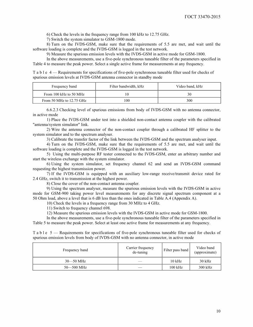
10) Check the levels in a frequency range from 30 MHz to 4 GHz. 11) Switch to frequency channel 698. 12) Measure the spurious emission levels with the IVDS-GSM in active mode for GSM-1800. In the above measurements, use a five-pole synchronous tuneable filter of the parameters specified in
Table 5 to measure the peak power. Select at least one active frame for measurements at any frequency. T a b l e 5 — Requirements for specifications of five-pole synchronous tuneable filter used for checks of spurious emission levels from body of IVDS-GSM with no antenna connector, in active mode
Frequency band Carrier frequency de-tuning Filter pass band Video band
(approximate)
30—50 MHz — 10 kHz 30 kHz 50—500 MHz — 100 kHz 300 kHz
ГОСТ 33470-2015
11
Table 5 (continued)
Frequency band Carrier frequency de-tuning Filter pass band Video band
(approximate)
from 500 MHz to 4 GHz,
excluding transmission bands: P-GSM: 890—915 MHz; E-GSM: 880—915 MHz; GSM: 1710—1785 MHz;
(0—10) MHz; ≥ 10 MHz
≥ 20 MHz ≥ 30 MHz
(de-tuning from edge of transmission band)
100 kHz; 300 kHz
1 MHz 3 MHz
300 kHz; 1 MHz
3 MHz 3 MHz
In reception bands: GSM-900: 890—915 MHz; Extended GSM: 880—915 MHz; GSM-1800: 1710—1785 MHz
1.8—6 MHz
> 6 MHz (de-tuning from carrier
frequency)
30 kHz 100 kHz
100 kHz 300 kHz
6.6.2.4 Checking level of spurious emissions from body of IVDS-GSM with no antenna connector, in standby mode
1) Place the IVDS-GSM under test into a shielded non-contact antenna coupler with the calibrated "antenna/system simulator" link.
2) Wire the antenna connector of the non-contact coupler through a calibrated HF splitter to the system simulator and to the spectrum analyser.
3) Calibrate the transfer factor of the link between the IVDS-GSM and the spectrum analyser input. 4) Switch the system simulator to GSM-900 mode. 5) Turn on the IVDS-GSM, make sure that the requirements of 5.5 are met, and wait until the
software loading is complete and the IVDS-GSM is logged in the test network. 6) If the IVDS-GSM is equipped with an auxiliary low-range receive/transmit device rated for
2.4 GHz, switch it to transmission at the highest power. 7) Close the cover of the non-contact antenna coupler. 8) Using the spectrum analyser, measure the spurious emission levels with the IVDS-GSM in
standby mode for GSM-900 taking power level measurements for any discrete signal spectrum component at a 50 Ohm load, above a level that is 6 dB less than the ones indicated in Table A.5 (Appendix A).
9) Check the levels in a frequency range from 30 MHz to 4 GHz. 10) Switch the system simulator to GSM-1800 mode. 11) Turn on the IVDS-GSM, , make sure that the requirements of 5.5 are met, and wait until the
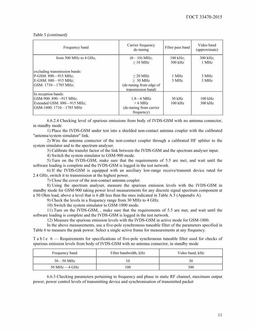
software loading is complete and the IVDS-GSM is logged in the test network. 12) Measure the spurious emission levels with the IVDS-GSM in active mode for GSM-1800. In the above measurements, use a five-pole synchronous tuneable filter of the parameters specified in
Table 6 to measure the peak power. Select a single active frame for measurements at any frequency. T a b l e 6 — Requirements for specifications of five-pole synchronous tuneable filter used for checks of spurious emission levels from body of IVDS-GSM with no antenna connector, in standby mode
Frequency band Filter bandwidth, kHz Video band, kHz
30—50 MHz 10 30 50 MHz —4 GHz 100 300
6.6.3 Checking parameters pertaining to frequency and phase in static RF channel, maximum output
power, power control levels of transmitting device and synchronisation of transmitted packet
ГОСТ 33470-2015
12
6.6.3.1 GSM-900 mode: 1) Wire the antenna connector of the IVDS-GSM under test to the system simulator. If the IVDS-
GSM has no antenna connector, use a non-contact antenna coupler with the calibrated "antenna/system simulator" link.
2) Connect the data port of the system simulator to the data port of the host computer. 3) Turn on the host computer, and launch the system simulator control utility. 4) In the utility settings, set GSM-900 mode, specify initial "IVSD-GSM/system simulator" link data,
list of tests to be performed as well as upper and lower limits of measured parameters in accordance with A.2 and A.7 (Appendix A), then run the utility.
5) Turn on the IVDS-GSM, make sure that the requirements of 5.5 are met, and wait until the software loading is complete and the IVDS-GSM is logged in the test network.
6) Using the system simulator, initiate a call to IVDS-GSM and make sure that the connection is established.
7) The subsequent checks are performed automatically, and the resulting report that will appear on the computer screen will include the measured parameter values: frequency and phase errors in static RF channel (see A.2, Appendix A), maximum output power, power control levels of the transmitting device, synchronisation of the transmitted packet (see A.7, Appendix A), as well as the data indicating whether the measured parameters correspond to the ones specified in the initial settings as per A.2 (Appendix A).
8) Print the test records for their inclusion in the test report. 6.6.3.2 GSM-1800 mode: 1) Wire the antenna connector of the IVDS-GSM under test to the system simulator. If the IVDS-
GSM has no antenna connector, use a non-contact antenna coupler with the calibrated "antenna/system simulator" link.
2) Connect the data port of the system simulator to the data port of the host computer. 3) Turn on the host computer, and launch the system simulator control utility. 4) In the utility settings, set GSM-1800 mode, specify initial " IVSD-GSM/system simulator" link
data, list of tests to be performed as well as upper and lower limits of measured parameters in accordance with A.2 and A.7 (Appendix A), then run the utility.
5) Turn on the IVDS-GSM, make sure that the requirements of 5.5 are met, and wait until the software loading is complete and the IVDS-GSM is logged in the test network.
6) Using the multi-purpose RF tester connected to the IVDS-GSM, enter number 1234567890 and initiate a call with the system simulator.
7) The subsequent checks are performed automatically, and the resulting report that will appear on the computer screen will include the measured parameter values: frequency and phase in static RF channel (see A.2, Appendix A), maximum output power, power control levels of the transmitting device, synchronisation of the transmitted packet (see A.7, Appendix A), as well as the data indicating whether the measured parameters correspond to the ones in specified the initial settings as per A.2 (Appendix A).
8) Print the test records for their inclusion in the test report. 6.6.3.3 The parameters pertaining to the frequency and phase in static RF channel, maximum output
power, power control levels of the transmitting device and synchronisation of the transmitted packet shall be checked:
a) for 8PSK modulation (EDGE): in accordance with [5] (clasue 13.17); b) for multi-slot operation (HSCSD and GPRS): in accordance with [5] (clause 13.16). 6.6.3.4 Repeat the tests as per 6.6.3.1—6.6.3.3 in extreme climatic conditions taking into account the
requirements of 6.4.2. 6.6.3.5 Repeat the tests as per 6.6.3.1—6.6.3.3 under exposure to mechanical impacts taking into
account the requirements of 6.4.3. 6.6.4 Checking levels of out-of-band IVDS-GSM emissions due to modulation 6.6.4.1 Checking levels of out-of-band IVDS-GSM emissions due to modulation in GSM-900 mode 1) Wire the antenna connector of the IVDS-GSM under test through a calibrated HF splitter to the
system simulator and to the spectrum analyser. If the IVDS-GSM has no antenna connector, use a non-contact antenna coupler with the calibrated "antenna/system simulator" link.
ГОСТ 33470-2015
13
2) Turn on the system simulator in GSM-900 mode. 3) Turn on the IVDS-GSM, make sure that the requirements of 5.5 are met, and wait until the
software loading is complete and the IVDS-GSM is logged in the test network. 4) Using the multi-purpose RF tester connected to the IVDS-GSM, enter an arbitrary number and
start the wireless exchange with the system simulator. 5) Using the system simulator, set frequency channel 62. 6) Send an IVDS-GSM command requesting the highest transmission power. 7) If the IVDS-GSM is equipped with an auxiliary low-range receive/transmit device rated for
2.4 GHz, switch it to transmission at the highest power. 8) Using the spectrum analyser, measure the out-of-band IVDS-GSM emission levels due to
modulation for GSM-900 in accordance with Table A.6 (Appendix A). 9) Set power level 19. 10) Repeat the measurements specified in 8) for the lowest transmission power level. 11) Repeat the measurements specified in 6) through 10) for bottom and top frequency channels. 6.6.4.2 Checking levels of out-of-band IVDS-GSM emissions due to modulation in GSM-1800 mode 1) Wire the antenna connector of the IVDS-GSM under test through a calibrated HF splitter to the
system simulator and to the spectrum analyser. If the IVDS-GSM has no antenna connector, use a non-contact antenna coupler with the calibrated "antenna/system simulator" link.
2) Turn on the system simulator in GSM-1800 mode. 3) Turn on the IVDS-GSM, make sure that the requirements of 5.5 are met, and wait until the
software loading is complete and the IVDS-GSM is logged in the test network. 4) Using the multi-purpose RF tester connected to the IVDS-GSM, enter an arbitrary number and
start the wireless exchange with the system simulator. 5) Using the system simulator, set frequency channel 698. 6) Send an IVDS-GSM command requesting the highest transmission power. 7) If the IVDS-GSM is equipped with an auxiliary low-range receive/transmit device rated for 2.4
GHz, switch it to transmission at the highest power. 8) Using the spectrum analyser, measure the out-of-band IVDS-GSM emission levels due to
modulation for GSM-1800 in accordance with Table A.7 (Appendix A). 9) Set power level 19. 10) Repeat the measurements specified in 8) for the lowest transmission power level. 11) Repeat the measurements specified in 6) through 10) for bottom and top frequency channels. 6.6.4.3 The out-of-band component levels of the IVDS-GSM due to modulation shall be checked in
accordance with [10 (clause 3.17.4)] for 8PSK modulation (EDGE), and in accordance with [10 (clause 3.18.4)] for multi-slot operation (HSCSD and GPRS).
6.6.4.3 The out-of-band component levels of the IVDS-GSM due to modulation shall be checked in accordance with [5] (clause 13.17.4)] for 8PSK modulation (EDGE), and in accordance with [5] (clause 13.8.4)] for multi-slot operation (HSCSD and GPRS).
6.6.5 Checking levels of out-of-band IVDS-GSM emissions due to transients in transmitter 6.6.5.1 Checking levels of out-of-band IVDS-GSM emissions due to transients during transmitter
power switches in GSM-900 mode: 1) Wire the antenna connector of the IVDS-GSM under test through a calibrated HF splitter to the
system simulator and to the spectrum analyser. If the IVDS-GSM has no antenna connector, use a non-contact antenna coupler with the calibrated "antenna/system simulator" link.
2) Connect the sync output of the system simulator to the external sync input of the spectrum analyser. Switch the spectrum analyser to standby mode waiting for external sync signals.
ГОСТ 33470-2015
14
3) Turn on the system simulator in GSM-900 mode. 4) Turn on the IVDS-GSM, make sure that the requirements of 5.5 are met, and wait until the
software loading is complete and the IVDS-GSM is logged in the test network. 5) Using the multi-purpose RF tester connected to the IVDS-GSM, enter an arbitrary number and
start the wireless exchange with the system simulator. 6) Using the system simulator, set frequency channel 62. 7) Send an IVDS-GSM command requesting the highest transmission power. 8) Send a command requesting the transmission power switch to the next lower level. 9) Using the spectrum analyser, measure the out-of-band IVDS-GSM emission levels due to
transients during transmitter power switches for GSM-900 in accordance with Table A.8 (Appendix 11). 10) Repeat the measurements twice decreasing the power by two levels successively. 11) Set power level 19. 12) Send a command requesting the transmission power switch to the next higher level. 13) Repeat the measurements three times increasing the power by three levels successively. 14) Repeat the measurements specified in 7) through 13) for bottom and top frequency channels. 6.6.5.2 Checking levels of out-of-band IVDS-GSM emissions due to transients during transmitter
power switches in GSM-1800 mode 1) Wire the antenna connector of the IVDS-GSM under test through a calibrated HF splitter to the
system simulator and to the spectrum analyser. If the IVDS-GSM has no antenna connector, use a non-contact antenna coupler with the calibrated "antenna/system simulator" link.
2) Connect the sync output of the system simulator to the external sync input of the spectrum analyser. Switch the spectrum analyser to standby mode waiting for external sync signals.
3) Turn on the system simulator in GSM-1800 mode. 4) Turn on the IVDS-GSM, make sure that the requirements of 5.5 are met, and wait until the
software loading is complete and the IVDS-GSM is logged in the test network. 5) Using the multi-purpose RF tester connected to the IVDS-GSM, enter an arbitrary number and
start the wireless exchange with the system simulator. 6) Using the system simulator, set frequency channel 698. 7) Send an IVDS-GSM command requesting the highest transmission power. 8) Send a command requesting the transmission power switch to the next lower level. 9) Using the spectrum analyser, measure the out-of-band IVDS-GSM emission levels due to
transients during transmitter power switches for GSM-1800 in accordance with Table A.9 (Appendix A). 10) Repeat the measurements twice decreasing the power by two levels successively. 11) Set power level 15. 12) Send a command requesting the transmission power switch to the next higher level. 13) Repeat the measurements three times increasing the power by three levels successively. 14) Repeat the measurements specified in 7) through 13) for bottom and top frequency channels. 6.6.5.3 The out-of-band component levels due to transients during IVDS-GSM transmitter power
switches shall be checked in accordance with [5] (clause 13.17.4)] for 8PSK modulation (EDGE) and in accordance with [5] (clause 13.8.4) for multi-slot operation (HSCSD and GPRS).
6.7 Methods of IVDS-GSM tests in regard to functional parameters and properties
6.7.1 Checking availability of International Mobile Station Equipment Identity (IMEI) 1) Wire the IVDS-GSM antenna connector to the system simulator. If the IVDS-GSM has no
antenna connector, use a non-contact antenna coupler with the calibrated "antenna/system simulator" link.
ГОСТ 33470-2015
15
2) Turn on the IVDS-GSM, make sure that the requirements of 5.5 are met, and wait until the software loading is complete and the IVDS-GSM is logged in the test network. On the system simulator screen, take note of the IMEI code read from the IVDS-GSM.
3) Compare the IMEI code read by the system simulator with the one indicated in the general type description for certification of IVDS-GSM samples.
6.7.2 Checking performance of procedures used for call receiving; establishing, maintaining and closing GSM-900 connections; ensuring stability of established GSM-900 connection in cases of channel switchover and of transition to GSM-1800 sub-band
1) Wire the IVDS-GSM antenna connector to the system simulator. If the IVDS-GSM has no antenna connector, use a non-contact antenna coupler with the calibrated "antenna/system simulator" link.
2) Turn on the IVDS-GSM, wait until the software loading is complete and the IVDS-GSM is logged in the test network.
3) Using the system simulator, start the procedure used to call the IVDS-GSM, with the bottom frequency channel selected in the band under test (channel 1 for GSM, channel 975 for E-GSM).
4) When the call from the system simulator arrives at the IVDS-GSM, set the IVDS-GSM off-hook and establish a wireless data link between the simulator and the IVDS-GSM using test GSM signals with GMSK modulation.
5) Using the system simulator, send an IVDS-GSM command requesting the highest transmission power, which is power level 5 for GSM-900.
6) Check the stability of wireless communication for 1 min. 7) Using the system simulator, send a command for switching to frequency channel 62 (medium
frequency GSM-900 channel) and check the stability of wireless communication for 1 min. 8) Using the system simulator, send a command for switching to frequency channel 124 (top
frequency GSM-900 channel) and check the stability of wireless communication for 1 min. 9) Using the system simulator, send a command for switching to frequency channel 512 (bottom
frequency GSM-1800 channel) and check the stability of wireless communication for 1 min. 10) Repeat the procedure of 5) through 9) three times. 11) Release the connection by hanging up from the IVDS-GSM side with the help of the system
simulator. 6.7.3 Checking performance of procedures used for calling and call receiving; establishing,
maintaining and closing GSM-1800 connections; ensuring stability of established GSM-1800 connection in cases of channel switchover and of transition to GSM-900 sub-band
1) Wire the IVDS-GSM antenna connector to the system simulator. If the IVDS-GSM has no antenna connector, use a non-contact antenna coupler with the calibrated "antenna/system simulator" link.
2) Turn on the IVDS-GSM, wait until the software loading is complete and the IVDS-GSM is logged in the test network.
3) Using the system simulator, start the procedure used to call the IVDS-GSM, with the bottom frequency channel selected in the band under test (channel 512).
4) When the call from the system simulator arrives at the IVDS-GSM, set the IVDS-GSM off-hook and establish a wireless data link between the simulator and the IVDS-GSM using test GSM signals with GMSK modulation.
5) Using the system simulator, send an IVDS-GSM command requesting the highest transmission power. For GSM-1800, power level 0.
6) Check the stability of wireless communication for 1 min. 7) Using the system simulator, send a command for switching to frequency channel 669 (medium
frequency GSM-1800 channel) and check the stability of wireless communication for 1 min. 8) Using the system simulator, send a command for switching to frequency channel 885 (top
frequency GSM-1800 channel) and check the stability of wireless communication for 1 min. 9) Using the system simulator, send a command for switching to frequency channel 1 (bottom
frequency GSM-900 channel) and check the stability of wireless communication for 1 min. 10) Repeat the procedure of 5) through 9) three times. 11) Release the connection from the system simulator side.
ГОСТ 33470-2015
16
7 Test methods of in-vehicle emergency call device/system with respect to
implementation of UMTS modem functions 7.1 Test item
7.1.1 The test item shall be an IVDS-UMTS sample in part of IVDS hardware/software solutions implementing the functionality of the wireless UMTS communication module that is included in the IVDS and intended for operation in 900 and 2000 MHz UMTS bands with duplex frequency separation and frequency-code separation of wireless channels.
7.1.2 The requirements for parameters and functional properties of UMTS modems are given in Appendix B for modems operating in the 900 MHz band, and in Appendix C for modems operating in 2000 MHz band.
7.1.3 Samples submitted to tests shall be selected by an employee of the testing laboratory (certification body) from a batch of finished products that has been accepted by the manufacturer's QC. Based on the results of sampling, an Act shall be compiled in the form specified in Appendix D.
7.2 Purpose of tests
The tests are aimed at the verification of IVDS-UMTS conformity to the requirements established in GOST 33464, and in Appendices B and C.
7.3 Test scope
7.3.1 Three IVDS-UMTS samples shall be submitted to tests after their sampling in accordance with 7.1.3, equipped and completed as per GOST 33464 (see sections 5 and 21, respectively).
Where justified, the number of IVDS-UMTS samples may be changed as agreed with the testing laboratory.
N o t e — As agreed with the testing laboratory, the tests of IVDS-UMTS samples with a built-in antenna may be carried out for the samples with a special remote RF process connector. Given this, the built-in antenna shall be decoupled.
7.3.2 During the IVDS-UMTS tests, the conformity is checked against the requirements established for:
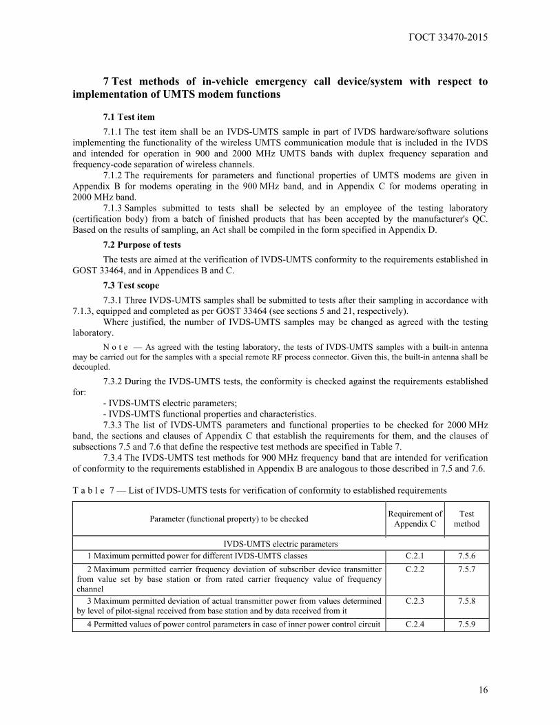
- IVDS-UMTS electric parameters; - IVDS-UMTS functional properties and characteristics. 7.3.3 The list of IVDS-UMTS parameters and functional properties to be checked for 2000 MHz
band, the sections and clauses of Appendix C that establish the requirements for them, and the clauses of subsections 7.5 and 7.6 that define the respective test methods are specified in Table 7.
7.3.4 The IVDS-UMTS test methods for 900 MHz frequency band that are intended for verification of conformity to the requirements established in Appendix B are analogous to those described in 7.5 and 7.6. T a b l e 7 — List of IVDS-UMTS tests for verification of conformity to established requirements
Parameter (functional property) to be checked Requirement of Appendix C
Test method
IVDS-UMTS electric parameters 1 Maximum permitted power for different IVDS-UMTS classes C.2.1 7.5.6 2 Maximum permitted carrier frequency deviation of subscriber device transmitter
from value set by base station or from rated carrier frequency value of frequency channel
C.2.2 7.5.7
3 Maximum permitted deviation of actual transmitter power from values determined by level of pilot-signal received from base station and by data received from it
C.2.3 7.5.8
4 Permitted values of power control parameters in case of inner power control circuit C.2.4 7.5.9
ГОСТ 33470-2015
17
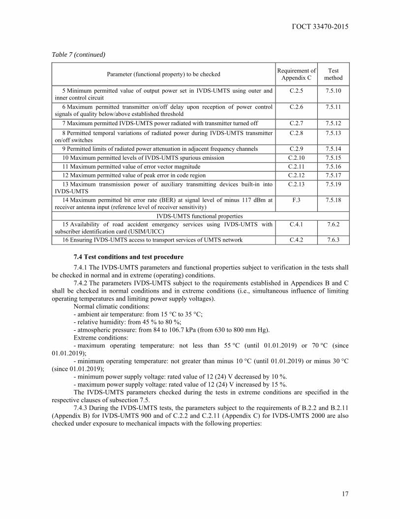
Table 7 (continued)
Parameter (functional property) to be checked Requirement of Appendix C
Test method
5 Minimum permitted value of output power set in IVDS-UMTS using outer and inner control circuit
C.2.5 7.5.10
6 Maximum permitted transmitter on/off delay upon reception of power control signals of quality below/above established threshold
C.2.6 7.5.11
7 Maximum permitted IVDS-UMTS power radiated with transmitter turned off C.2.7 7.5.12 8 Permitted temporal variations of radiated power during IVDS-UMTS transmitter
on/off switches C.2.8 7.5.13
9 Permitted limits of radiated power attenuation in adjacent frequency channels C.2.9 7.5.14 10 Maximum permitted levels of IVDS-UMTS spurious emission C.2.10 7.5.15 11 Maximum permitted value of error vector magnitude C.2.11 7.5.16 12 Maximum permitted value of peak error in code region C.2.12 7.5.17 13 Maximum transmission power of auxiliary transmitting devices built-in into
IVDS-UMTS C.2.13 7.5.19
14 Maximum permitted bit error rate (BER) at signal level of minus 117 dBm at receiver antenna input (reference level of receiver sensitivity)
F.3 7.5.18
IVDS-UMTS functional properties 15 Availability of road accident emergency services using IVDS-UMTS with
subscriber identification card (USIM/UICC) C.4.1 7.6.2
16 Ensuring IVDS-UMTS access to transport services of UMTS network C.4.2 7.6.3
7.4 Test conditions and test procedure
7.4.1 The IVDS-UMTS parameters and functional properties subject to verification in the tests shall be checked in normal and in extreme (operating) conditions.
7.4.2 The parameters IVDS-UMTS subject to the requirements established in Appendices B and C shall be checked in normal conditions and in extreme conditions (i.e., simultaneous influence of limiting operating temperatures and limiting power supply voltages).
Normal climatic conditions: - ambient air temperature: from 15 °C to 35 °C; - relative humidity: from 45 % to 80 %; - atmospheric pressure: from 84 to 106.7 kPa (from 630 to 800 mm Hg). Extreme conditions: - maximum operating temperature: not less than 55 °C (until 01.01.2019) or 70 °C (since
01.01.2019); - minimum operating temperature: not greater than minus 10 °C (until 01.01.2019) or minus 30 °C
(since 01.01.2019); - minimum power supply voltage: rated value of 12 (24) V decreased by 10 %. - maximum power supply voltage: rated value of 12 (24) V increased by 15 %. The IVDS-UMTS parameters checked during the tests in extreme conditions are specified in the
respective clauses of subsection 7.5. 7.4.3 During the IVDS-UMTS tests, the parameters subject to the requirements of B.2.2 and B.2.11
(Appendix B) for IVDS-UMTS 900 and of C.2.2 and C.2.11 (Appendix C) for IVDS-UMTS 2000 are also checked under exposure to mechanical impacts with the following properties:
ГОСТ 33470-2015
18
- broadband vibration in 5...20 Hz band, with the spectrum density of vibration acceleration equal to
0.96 m2/s3; - broadband vibration in 20...500 Hz band, with the spectrum density of vibration acceleration equal
to 0.96 m2/s3 at a 20 Hz frequency and 3 dB/octave above it. 7.4.4 The tests shall be carried out by persons certified in accordance with the established procedure. 7.4.5 Only persons who have passed the safety training and qualified for a safety group not less than
3 in regard to operation with electrical installations rated up to 1000 V may be admitted to operation with testing equipment.
7.4.6 In preparation to tests, the safety (electrical safety, fire safety, etc.) activities as well as the ones related to grounding, metal coating and electrical insulation specified in the operating documentation for testing equipment shall be completed.
7.4.7 The requirements of GOST 12.1.019, GOST 12.1.030 and GOST 12.3.019 and as well as those of the operating documentation for measuring instruments and testing equipment shall be observed during the tests.
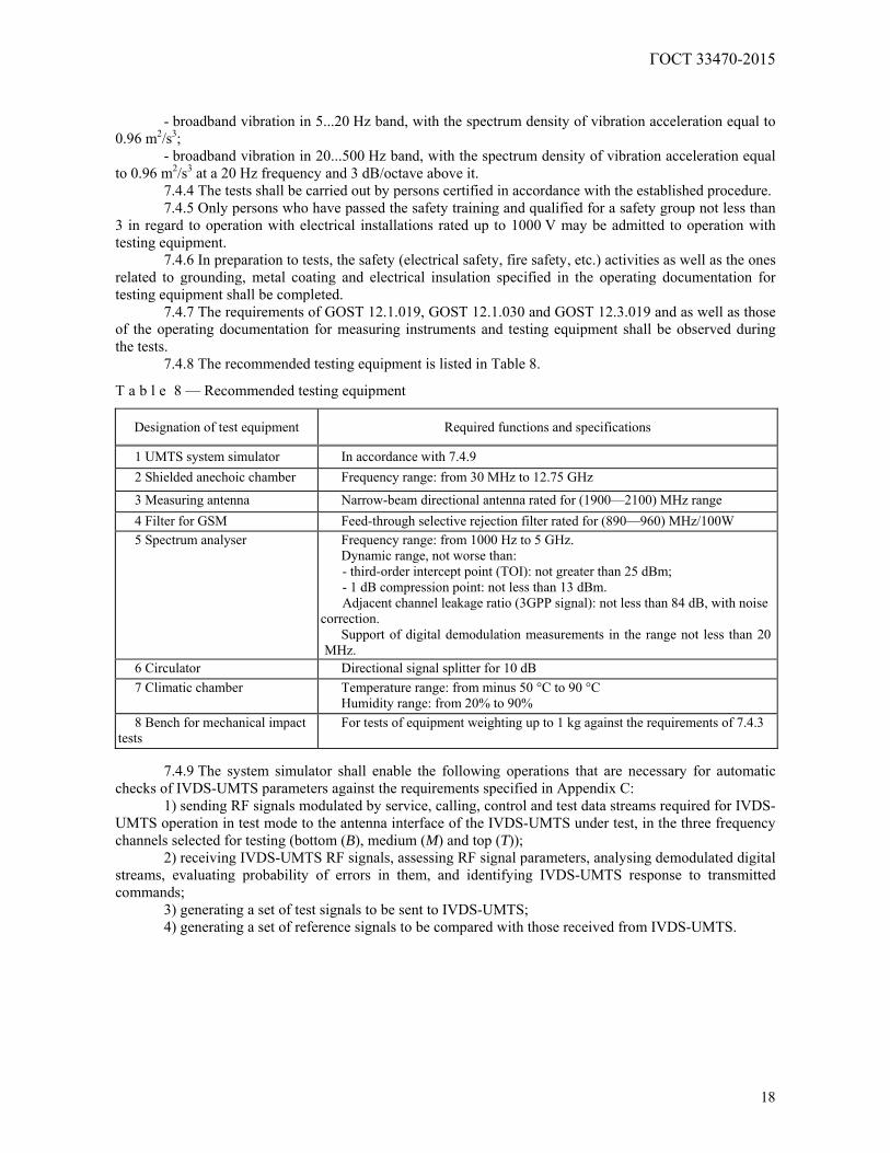
7.4.8 The recommended testing equipment is listed in Table 8.
T a b l e 8 — Recommended testing equipment
Designation of test equipment Required functions and specifications
1 UMTS system simulator In accordance with 7.4.9 2 Shielded anechoic chamber Frequency range: from 30 MHz to 12.75 GHz
3 Measuring antenna Narrow-beam directional antenna rated for (1900—2100) MHz range 4 Filter for GSM Feed-through selective rejection filter rated for (890—960) MHz/100W 5 Spectrum analyser Frequency range: from 1000 Hz to 5 GHz.
Dynamic range, not worse than: - third-order intercept point (TOI): not greater than 25 dBm; - 1 dB compression point: not less than 13 dBm. Adjacent channel leakage ratio (3GPP signal): not less than 84 dB, with noise
correction. Support of digital demodulation measurements in the range not less than 20
MHz. 6 Circulator Directional signal splitter for 10 dB 7 Climatic chamber Temperature range: from minus 50 °C to 90 °C
Humidity range: from 20% to 90% 8 Bench for mechanical impact
tests For tests of equipment weighting up to 1 kg against the requirements of 7.4.3
7.4.9 The system simulator shall enable the following operations that are necessary for automatic
checks of IVDS-UMTS parameters against the requirements specified in Appendix C: 1) sending RF signals modulated by service, calling, control and test data streams required for IVDS-
UMTS operation in test mode to the antenna interface of the IVDS-UMTS under test, in the three frequency channels selected for testing (bottom (B), medium (M) and top (T));
2) receiving IVDS-UMTS RF signals, assessing RF signal parameters, analysing demodulated digital streams, evaluating probability of errors in them, and identifying IVDS-UMTS response to transmitted commands;
3) generating a set of test signals to be sent to IVDS-UMTS; 4) generating a set of reference signals to be compared with those received from IVDS-UMTS.
ГОСТ 33470-2015
19
Connection between the system simulator and the IVDS-UMTS under test is established using the
basic connection setup and loopback test procedure programmed in the system simulator. After the connection between the system simulator and the IVDS-UMTS under test is established,
the system simulator display shall, in addition to any other data, indicate the IMEI of the IVDS-UMTS under test.
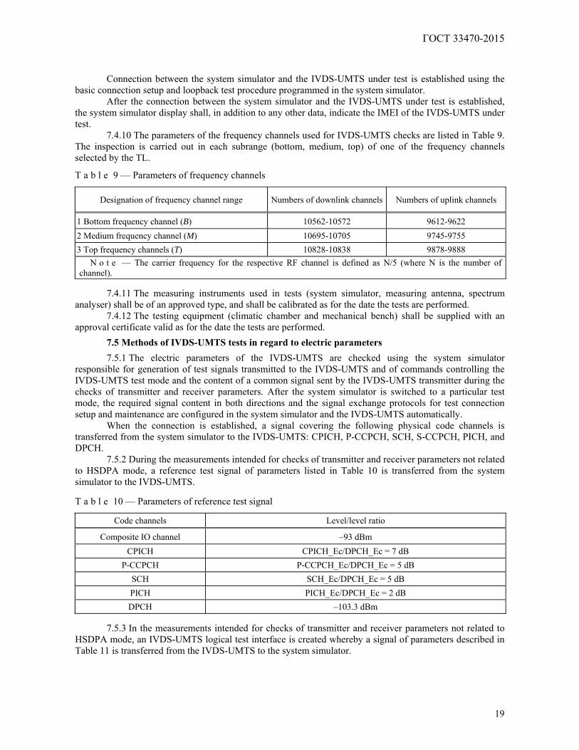
7.4.10 The parameters of the frequency channels used for IVDS-UMTS checks are listed in Table 9. The inspection is carried out in each subrange (bottom, medium, top) of one of the frequency channels selected by the TL.
T a b l e 9 — Parameters of frequency channels
Designation of frequency channel range Numbers of downlink channels Numbers of uplink channels
1 Bottom frequency channel (B) 10562-10572 9612-9622 2 Medium frequency channel (M) 10695-10705 9745-9755 3 Top frequency channels (T) 10828-10838 9878-9888
N o t e — The carrier frequency for the respective RF channel is defined as N/5 (where N is the number of channel).
7.4.11 The measuring instruments used in tests (system simulator, measuring antenna, spectrum
analyser) shall be of an approved type, and shall be calibrated as for the date the tests are performed. 7.4.12 The testing equipment (climatic chamber and mechanical bench) shall be supplied with an
approval certificate valid as for the date the tests are performed.
7.5 Methods of IVDS-UMTS tests in regard to electric parameters
7.5.1 The electric parameters of the IVDS-UMTS are checked using the system simulator responsible for generation of test signals transmitted to the IVDS-UMTS and of commands controlling the IVDS-UMTS test mode and the content of a common signal sent by the IVDS-UMTS transmitter during the checks of transmitter and receiver parameters. After the system simulator is switched to a particular test mode, the required signal content in both directions and the signal exchange protocols for test connection setup and maintenance are configured in the system simulator and the IVDS-UMTS automatically.
When the connection is established, a signal covering the following physical code channels is transferred from the system simulator to the IVDS-UMTS: CPICH, P-CCPCH, SCH, S-CCPCH, PICH, and DPCH.
7.5.2 During the measurements intended for checks of transmitter and receiver parameters not related to HSDPA mode, a reference test signal of parameters listed in Table 10 is transferred from the system simulator to the IVDS-UMTS. T a b l e 10 — Parameters of reference test signal
Code channels Level/level ratio
Composite IO channel –93 dBm CPICH CPICH_Ec/DPCH_Ec = 7 dB
P-CCPCH P-CCPCH_Ec/DPCH_Ec = 5 dB SCH SCH_Ec/DPCH_Ec = 5 dB PICH PICH_Ec/DPCH_Ec = 2 dB DPCH –103.3 dBm
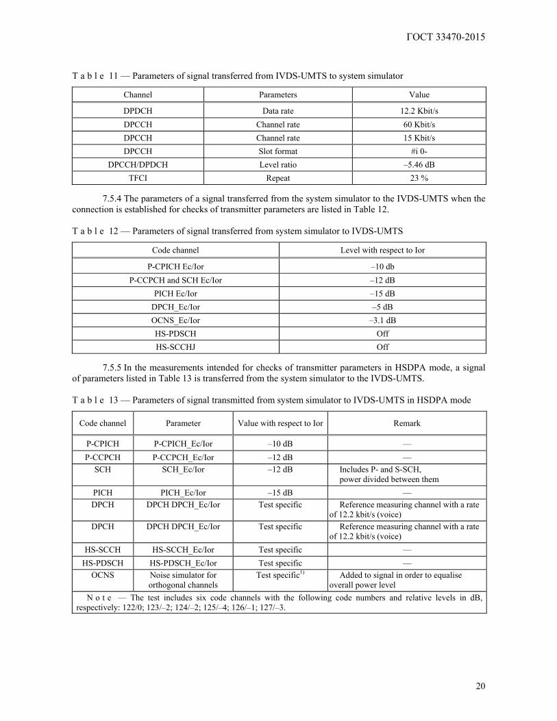
7.5.3 In the measurements intended for checks of transmitter and receiver parameters not related to
HSDPA mode, an IVDS-UMTS logical test interface is created whereby a signal of parameters described in Table 11 is transferred from the IVDS-UMTS to the system simulator.
ГОСТ 33470-2015
20
T a b l e 11 — Parameters of signal transferred from IVDS-UMTS to system simulator
Channel Parameters Value
DPDCH Data rate 12.2 Kbit/s DPCCH Channel rate 60 Kbit/s DPCCH Channel rate 15 Kbit/s DPCCH Slot format #i 0-
DPCCH/DPDCH Level ratio –5.46 dB TFCI Repeat 23 %
7.5.4 The parameters of a signal transferred from the system simulator to the IVDS-UMTS when the
connection is established for checks of transmitter parameters are listed in Table 12. T a b l e 12 — Parameters of signal transferred from system simulator to IVDS-UMTS
Code channel Level with respect to Ior
P-CPICH Ec/Ior –10 db P-CCPCH and SCH Ec/Ior –12 dB
PICH Ec/Ior –15 dB DPCH_Ec/Ior –5 dB OCNS_Ec/Ior –3.1 dB HS-PDSCH Off HS-SCCHJ Off
7.5.5 In the measurements intended for checks of transmitter parameters in HSDPA mode, a signal
of parameters listed in Table 13 is transferred from the system simulator to the IVDS-UMTS. T a b l e 13 — Parameters of signal transmitted from system simulator to IVDS-UMTS in HSDPA mode
Code channel Parameter Value with respect to Ior Remark
P-CPICH P-CPICH_Ec/Ior –10 dB — P-CCPCH P-CCPCH_Ec/Ior –12 dB —
SCH SCH_Ec/Ior –12 dB Includes P- and S-SCH, power divided between them
PICH PICH_Ec/Ior –15 dB — DPCH DPCH DPCH_Ec/Ior Test specific Reference measuring channel with a rate
of 12.2 kbit/s (voice) DPCH DPCH DPCH_Ec/Ior Test specific Reference measuring channel with a rate
of 12.2 kbit/s (voice) HS-SCCH HS-SCCH_Ec/Ior Test specific —
HS-PDSCH HS-PDSCH_Ec/Ior Test specific — OCNS Noise simulator for
orthogonal channels Test specific1) Added to signal in order to equalise
overall power level N o t e — The test includes six code channels with the following code numbers and relative levels in dB,
respectively: 122/0; 123/–2; 124/–2; 125/–4; 126/–1; 127/–3.
ГОСТ 33470-2015
21
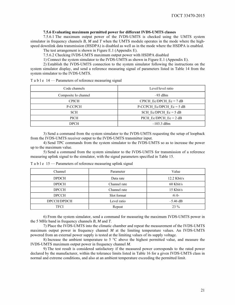
7.5.6 Evaluating maximum permitted power for different IVDS-UMTS classes 7.5.6.1 The maximum output power of the IVDS-UMTS is checked using the UMTS system
simulator in frequency channels B, M and T when the UMTS module operates in the mode where the high-speed downlink data transmission (HSDPA) is disabled as well as in the mode where the HSDPA is enabled.
The test arrangement is shown in Figure E.1 (Appendix E). 7.5.6.2 Checking IVDS-UMTS maximum output power with HSDPA disabled 1) Connect the system simulator to the IVDS-UMTS as shown in Figure E.1 (Appendix E). 2) Establish the IVDS-UMTS connection to the system simulator following the instructions on the
system simulator display, and send a reference measuring signal of parameters listed in Table 14 from the system simulator to the IVDS-UMTS.
T a b l e 14 — Parameters of reference measuring signal
Code channels Level/level ratio
Composite Io channel –93 dBm CPICH CPICH_Ec/DPCH_Ec = 7 dB
P-CCPCH P-CCPCH_Ec/DPCH_Ec = 5 dB SCH SCH_Ec/DPCH_Ec = 5 dB PICH PICH_Ec/DPCH_Ec = 2 dB DPCH –103.3 dBm
3) Send a command from the system simulator to the IVDS-UMTS requesting the setup of loopback
from the IVDS-UMTS receiver output to the IVDS-UMTS transmitter input. 4) Send TPC commands from the system simulator to the IVDS-UMTS so as to increase the power
up to the maximum value. 5) Send a command from the system simulator to the IVDS-UMTS for transmission of a reference
measuring uplink signal to the simulator, with the signal parameters specified in Table 15.
T a b l e 15 — Parameters of reference measuring uplink signal
Channel Parameter Value
DPDCH Data rate 12.2 Kbit/s DPDCH Channel rate 60 Kbit/s DPCCH Channel rate 15 Kbit/s DPCCH Slot format #i 0-
DPCCH/DPDCH Level ratio –5.46 dB TFCI Repeat 23 %
6) From the system simulator, send a command for measuring the maximum IVDS-UMTS power in
the 5 MHz band in frequency channels B, M and T. 7) Place the IVDS-UMTS into the climatic chamber and repeat the measurement of the IVDS-UMTS
maximum output power in frequency channel M at the limiting temperature values. An IVDS-UMTS powered from an external power supply is tested at the limiting values of its supply voltage.
8) Increase the ambient temperature to 5 °C above the highest permitted value, and measure the IVDS-UMTS maximum output power in frequency channel M.
9) The test result is considered satisfactory if the measured power corresponds to the rated power declared by the manufacturer, within the tolerance limits listed in Table 16 for a given IVDS-UMTS class in normal and extreme conditions, and also at an ambient temperature exceeding the permitted limit.
ГОСТ 33470-2015
22
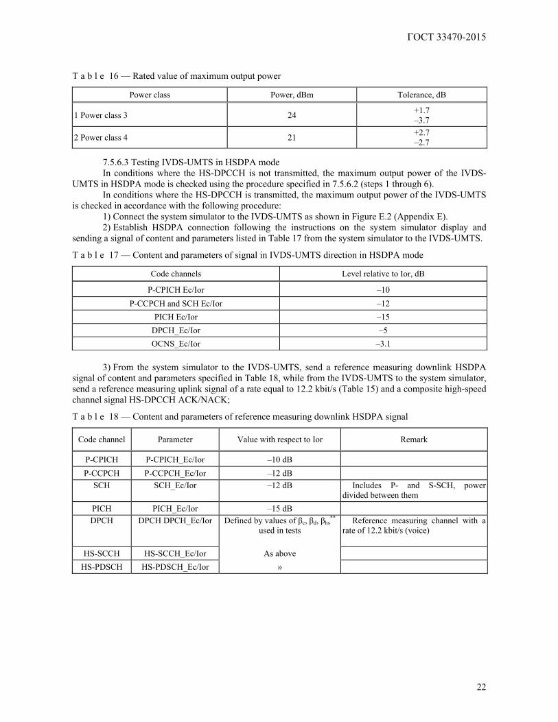
T a b l e 16 — Rated value of maximum output power
Power class Power, dBm Tolerance, dB
1 Power class 3 24 +1.7 –3.7
2 Power class 4 21 +2.7 –2.7
7.5.6.3 Testing IVDS-UMTS in HSDPA mode In conditions where the HS-DPCCH is not transmitted, the maximum output power of the IVDS-
UMTS in HSDPA mode is checked using the procedure specified in 7.5.6.2 (steps 1 through 6). In conditions where the HS-DPCCH is transmitted, the maximum output power of the IVDS-UMTS
is checked in accordance with the following procedure: 1) Connect the system simulator to the IVDS-UMTS as shown in Figure E.2 (Appendix E). 2) Establish HSDPA connection following the instructions on the system simulator display and
sending a signal of content and parameters listed in Table 17 from the system simulator to the IVDS-UMTS.
T a b l e 17 — Content and parameters of signal in IVDS-UMTS direction in HSDPA mode
Code channels Level relative to Ior, dB
P-CPICH Ec/Ior –10 P-CCPCH and SCH Ec/Ior –12
PICH Ec/Ior –15 DPCH_Ec/Ior –5 OCNS_Ec/Ior –3.1
3) From the system simulator to the IVDS-UMTS, send a reference measuring downlink HSDPA
signal of content and parameters specified in Table 18, while from the IVDS-UMTS to the system simulator, send a reference measuring uplink signal of a rate equal to 12.2 kbit/s (Table 15) and a composite high-speed channel signal HS-DPCCH ACK/NACK;
T a b l e 18 — Content and parameters of reference measuring downlink HSDPA signal
Code channel Parameter Value with respect to Ior Remark
P-CPICH P-CPICH_Ec/Ior –10 dB P-CCPCH P-CCPCH_Ec/Ior –12 dB
SCH SCH_Ec/Ior –12 dB Includes P- and S-SCH, power divided between them
PICH PICH_Ec/Ior –15 dB DPCH DPCH DPCH_Ec/Ior Defined by values of βс, βd, βhs
**
used in tests Reference measuring channel with a
rate of 12.2 kbit/s (voice)
HS-SCCH HS-SCCH_Ec/Ior As above
HS-PDSCH HS-PDSCH_Ec/Ior »
ГОСТ 33470-2015
23
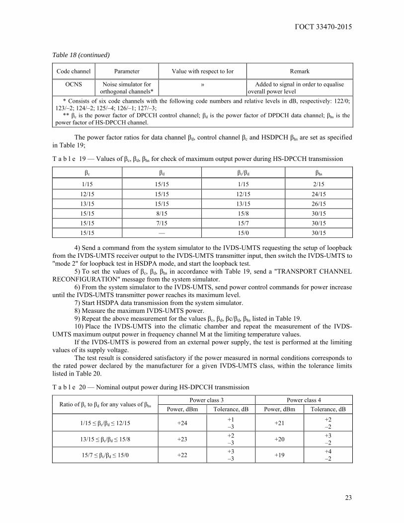
Table 18 (continued)
Code channel Parameter Value with respect to Ior Remark
OCNS Noise simulator for orthogonal channels*
» Added to signal in order to equalise overall power level
* Consists of six code channels with the following code numbers and relative levels in dB, respectively: 122/0; 123/–2; 124/–2; 125/–4; 126/–1; 127/–3;
** βс is the power factor of DPCCH control channel; βd is the power factor of DPDCH data channel; βhs is the power factor of HS-DPCCH channel.
The power factor ratios for data channel βd, control channel βс and HSDPCH βhs are set as specified
in Table 19; T a b l e 19 — Values of βс, βd, βhs for check of maximum output power during HS-DPCCH transmission
βс βd βс/βd βhs
1/15 15/15 1/15 2/15 12/15 15/15 12/15 24/15 13/15 15/15 13/15 26/15 15/15 8/15 15/8 30/15 15/15 7/15 15/7 30/15 15/15 — 15/0 30/15
4) Send a command from the system simulator to the IVDS-UMTS requesting the setup of loopback
from the IVDS-UMTS receiver output to the IVDS-UMTS transmitter input, then switch the IVDS-UMTS to "mode 2" for loopback test in HSDPA mode, and start the loopback test.
5) To set the values of βс, βd, βhs in accordance with Table 19, send a "TRANSPORT CHANNEL RECONFIGURATION" message from the system simulator.
6) From the system simulator to the IVDS-UMTS, send power control commands for power increase until the IVDS-UMTS transmitter power reaches its maximum level.
7) Start HSDPA data transmission from the system simulator. 8) Measure the maximum IVDS-UMTS power. 9) Repeat the above measurement for the values βс, βd, βc/βd, βhs listed in Table 19. 10) Place the IVDS-UMTS into the climatic chamber and repeat the measurement of the IVDS-
UMTS maximum output power in frequency channel M at the limiting temperature values. If the IVDS-UMTS is powered from an external power supply, the test is performed at the limiting
values of its supply voltage. The test result is considered satisfactory if the power measured in normal conditions corresponds to
the rated power declared by the manufacturer for a given IVDS-UMTS class, within the tolerance limits listed in Table 20. T a b l e 20 — Nominal output power during HS-DPCCH transmission
Power class 3 Power class 4 Ratio of βс to βd for any values of βhs Power, dBm Tolerance, dB Power, dBm Tolerance, dB
1/15 ≤ βс/βd ≤ 12/15 +24 +1 –3 +21 +2
–2
13/15 ≤ βс/βd ≤ 15/8 +23 +2 –3 +20 +3
–2
15/7 ≤ βс/βd ≤ 15/0 +22 +3 –3 +19 +4
–2
ГОСТ 33470-2015
24
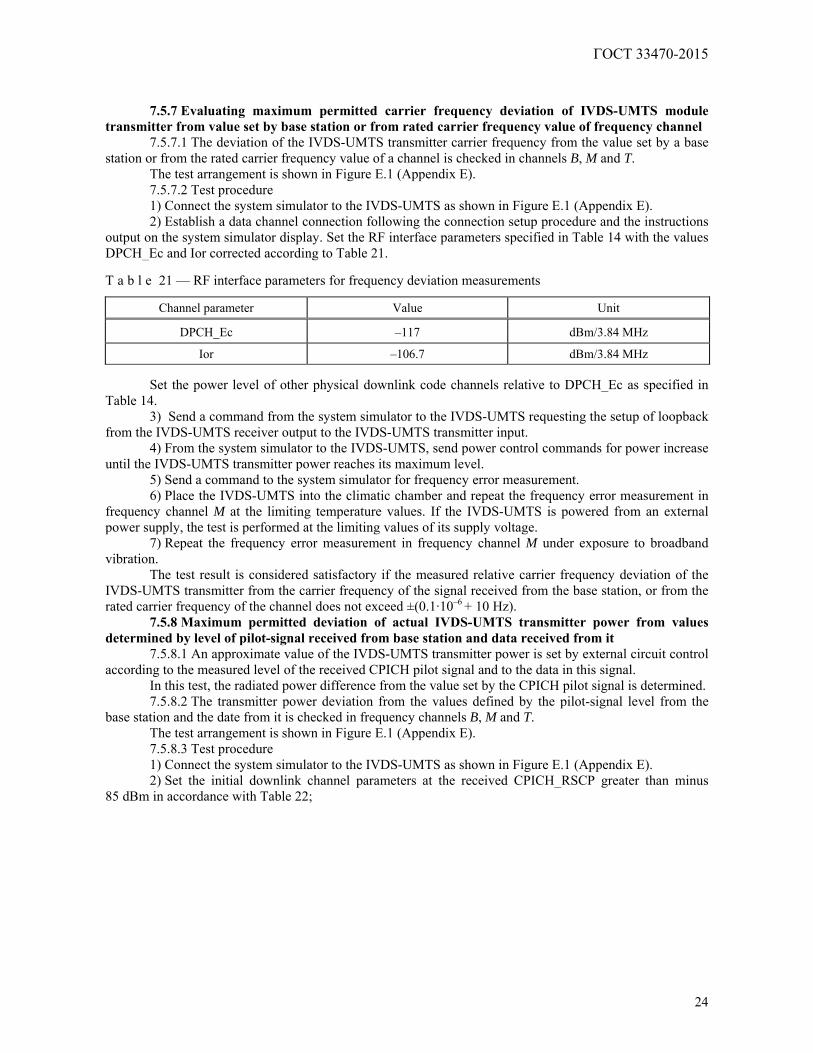
7.5.7 Evaluating maximum permitted carrier frequency deviation of IVDS-UMTS module
transmitter from value set by base station or from rated carrier frequency value of frequency channel 7.5.7.1 The deviation of the IVDS-UMTS transmitter carrier frequency from the value set by a base
station or from the rated carrier frequency value of a channel is checked in channels B, M and T. The test arrangement is shown in Figure E.1 (Appendix E). 7.5.7.2 Test procedure 1) Connect the system simulator to the IVDS-UMTS as shown in Figure E.1 (Appendix E). 2) Establish a data channel connection following the connection setup procedure and the instructions
output on the system simulator display. Set the RF interface parameters specified in Table 14 with the values DPCH_Ec and Ior corrected according to Table 21. T a b l e 21 — RF interface parameters for frequency deviation measurements
Channel parameter Value Unit
DPCH_Ec –117 dBm/3.84 MHz
Ior –106.7 dBm/3.84 MHz
Set the power level of other physical downlink code channels relative to DPCH_Ec as specified in Table 14.
3) Send a command from the system simulator to the IVDS-UMTS requesting the setup of loopback from the IVDS-UMTS receiver output to the IVDS-UMTS transmitter input.
4) From the system simulator to the IVDS-UMTS, send power control commands for power increase until the IVDS-UMTS transmitter power reaches its maximum level.
5) Send a command to the system simulator for frequency error measurement. 6) Place the IVDS-UMTS into the climatic chamber and repeat the frequency error measurement in
frequency channel M at the limiting temperature values. If the IVDS-UMTS is powered from an external power supply, the test is performed at the limiting values of its supply voltage.
7) Repeat the frequency error measurement in frequency channel M under exposure to broadband vibration.
The test result is considered satisfactory if the measured relative carrier frequency deviation of the IVDS-UMTS transmitter from the carrier frequency of the signal received from the base station, or from the rated carrier frequency of the channel does not exceed ±(0.1·10–6 + 10 Hz).
7.5.8 Maximum permitted deviation of actual IVDS-UMTS transmitter power from values determined by level of pilot-signal received from base station and data received from it
7.5.8.1 An approximate value of the IVDS-UMTS transmitter power is set by external circuit control according to the measured level of the received CPICH pilot signal and to the data in this signal.
In this test, the radiated power difference from the value set by the CPICH pilot signal is determined. 7.5.8.2 The transmitter power deviation from the values defined by the pilot-signal level from the
base station and the date from it is checked in frequency channels B, M and T. The test arrangement is shown in Figure E.1 (Appendix E). 7.5.8.3 Test procedure 1) Connect the system simulator to the IVDS-UMTS as shown in Figure E.1 (Appendix E). 2) Set the initial downlink channel parameters at the received CPICH_RSCP greater than minus
85 dBm in accordance with Table 22;
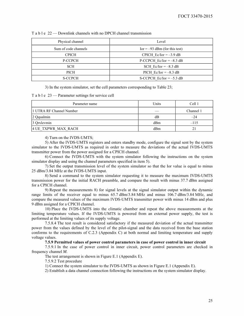
ГОСТ 33470-2015
25
T a b l e 22 — Downlink channels with no DPCH channel transmission
Physical channel Level
Sum of code channels Ior = –93 dBm (for this test) CPICH СРIСН_Ес/Iог = –3.9 dB
P-CCPCH P-CCPCH_Ес/Iог = –8.3 dB SCH SCH_Ec/Iог = –8.3 dB PICH РIСН_Ес/Iог = –8.3 dB
S-CCPCH S-CCPCH_Ec/Iог = –5.3 dB
3) In the system simulator, set the cell parameters corresponding to Table 23; T a b l e 23 — Parameter settings for service cell
Parameter name Units Cell 1
1 UTRA RF Channel Number — Channel 1 2 Qqualmin dB –24 3 Qrxlevmin dBm –115 4 UE_TXPWR_MAX_RACH dBm 21
4) Turn on the IVDS-UMTS; 5) After the IVDS-UMTS registers and enters standby mode, configure the signal sent by the system
simulator to the IVDS-UMTS as required in order to measure the deviations of the actual IVDS-UMTS transmitter power from the power assigned for a CPICH channel.
6) Connect the IVDS-UMTS with the system simulator following the instructions on the system simulator display and using the channel parameters specified in item 5).
7) Set the output transmission level of the system simulator so that the Ior value is equal to minus 25 dBm/3.84 MHz at the IVDS-UMTS input.
8) Send a command to the system simulator requesting it to measure the maximum IVDS-UMTS transmission power for the initial RACH preamble, and compare the result with minus 37.7 dBm assigned for a CPICH channel.
9) Repeat the measurements 8) for signal levels at the signal simulator output within the dynamic range limits of the receiver equal to minus 65.7 dBm/3.84 MHz and minus 106.7 dBm/3.84 MHz, and compare the measured values of the maximum IVDS-UMTS transmitter power with minus 14 dBm and plus 9 dBm assigned for a CPICH channel.
10) Place the IVDS-UMTS into the climatic chamber and repeat the above measurements at the limiting temperature values. If the IVDS-UMTS is powered from an external power supply, the test is performed at the limiting values of its supply voltage.
7.5.8.4 The test result is considered satisfactory if the measured deviation of the actual transmitter power from the values defined by the level of the pilot-signal and the data received from the base station conforms to the requirements of C.2.3 (Appendix C) at both normal and limiting temperature and supply voltage values.
7.5.9 Permitted values of power control parameters in case of power control in inner circuit 7.5.9.1 In the case of power control in inner circuit, power control parameters are checked in
frequency channel M. The test arrangement is shown in Figure E.1 (Appendix E). 7.5.9.2 Test procedure 1) Connect the system simulator to the IVDS-UMTS as shown in Figure E.1 (Appendix E). 2) Establish a data channel connection following the instructions on the system simulator display.
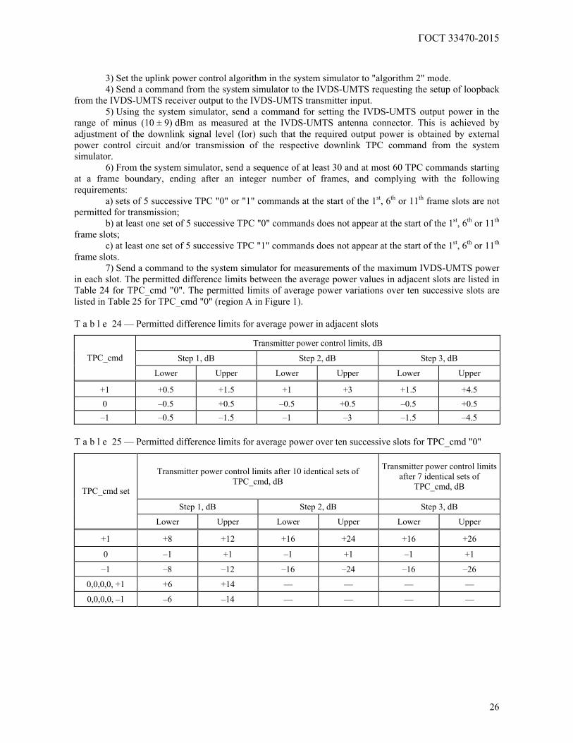
ГОСТ 33470-2015
26
3) Set the uplink power control algorithm in the system simulator to "algorithm 2" mode. 4) Send a command from the system simulator to the IVDS-UMTS requesting the setup of loopback
from the IVDS-UMTS receiver output to the IVDS-UMTS transmitter input. 5) Using the system simulator, send a command for setting the IVDS-UMTS output power in the
range of minus (10 ± 9) dBm as measured at the IVDS-UMTS antenna connector. This is achieved by adjustment of the downlink signal level (Ior) such that the required output power is obtained by external power control circuit and/or transmission of the respective downlink TPC command from the system simulator.
6) From the system simulator, send a sequence of at least 30 and at most 60 TPC commands starting at a frame boundary, ending after an integer number of frames, and complying with the following requirements:
a) sets of 5 successive TPC "0" or "1" commands at the start of the 1st, 6th or 11th frame slots are not permitted for transmission;
b) at least one set of 5 successive TPC "0" commands does not appear at the start of the 1st, 6th or 11th frame slots;
c) at least one set of 5 successive TPC "1" commands does not appear at the start of the 1st, 6th or 11th frame slots.
7) Send a command to the system simulator for measurements of the maximum IVDS-UMTS power in each slot. The permitted difference limits between the average power values in adjacent slots are listed in Table 24 for TPC_cmd "0". The permitted limits of average power variations over ten successive slots are listed in Table 25 for TPC_cmd "0" (region A in Figure 1). T a b l e 24 — Permitted difference limits for average power in adjacent slots
Transmitter power control limits, dB
Step 1, dB Step 2, dB Step 3, dB TPC_cmd
Lower Upper Lower Upper Lower Upper
+1 +0.5 +1.5 +1 +3 +1.5 +4.5 0 –0.5 +0.5 –0.5 +0.5 –0.5 +0.5 –1 –0.5 –1.5 –1 –3 –1.5 –4.5
T a b l e 25 — Permitted difference limits for average power over ten successive slots for TPC_cmd "0"
Transmitter power control limits after 10 identical sets of TPC_cmd, dB
Transmitter power control limits after 7 identical sets of
TPC_cmd, dB
Step 1, dB Step 2, dB Step 3, dB
TPC_cmd set
Lower Upper Lower Upper Lower Upper
+1 +8 +12 +16 +24 +16 +26
0 –1 +1 –1 +1 –1 +1
–1 –8 –12 –16 –24 –16 –26
0,0,0,0, +1 +6 +14 — — — —
0,0,0,0, –1 –6 –14 — — — —

ГОСТ 33470-2015
27
Figure 1
8) From the system simulator, send a sequence of 50 TPC commands consisting of "1". Each fifth
command must be "TPC_cmd+1" with a step size of 1 dB, and the remaining ones must be "TPC_cmd 0". 9) Send a command to the system simulator for power measurements in each slot. The permitted
difference limits between the average power values in adjacent slots are listed in Table 25. The permitted limits of average power variations over fifty successive slots are specified in Table 26 for "TPC_cmd {0,0,0,0,+1}" (region B in Figure 1).
10) From the system simulator, send a sequence of 50 TPC commands consisting of "0". 11) Send a command to the system simulator for power measurements in each slot. The permitted
difference limits for the average power in adjacent slots are specified in Table 25. 12) From the system simulator, send a sequence of 50 TPC commands consisting of "0". Each 5th
command must be "TPC_cmd -1" with a step size of 1 dB, and the remaining ones must be "TPC_cmd -0". The permitted limits of average power variations over fifty successive slots are specified in Table 25 for "TPC_cmd {0,0,0,0,-1}" (region C in Figure 1).
13) Set the uplink power control algorithm in the system simulator to "algorithm 1". 14) From the system simulator, send TPC command sequences consisting of "1" until the measured
IVDS-UMTS output power exceeds the maximum power threshold (region D in Figure 1). 15) From the system simulator, send a sequence of at least 160 TPC commands consisting of "0".
The permitted limits of average power variations over ten successive slots are specified in Table 26 for "TPC_cmd {0,0,0,0,-1}" (region E in Figure 1).
16) From the system simulator, send a sequence of at least 160 TPC commands consisting of "1". The permitted difference limits between the average power values in adjacent slots are listed in Table 25 for "TPC_cmd +1" with a step size of 1 dB (region F in Figure 1). The permitted limits of average power variations over ten successive slots for "TPC_cmd +1" command set with a step size of 1 dB are specified in Table 25.
17) From the system simulator, send the "PHYSICAL CHANNEL RECONFIGURATION" message with a command for setting the uplink power control step to 2 dB (power control "algorithm 1" is not changed).
18) From the system simulator, send sequences of at least 85 TPC commands consisting of "0" until the measured IVDS-UMTS output power reaches the minimum power threshold (region G in Figure 1). The permitted limits of average power variations over ten successive slots are specified in Table 25 for "TPC_cmd -1" command set with a step size of 2 dB.

ГОСТ 33470-2015
28
19) From the system simulator, send TPC command sequences consisting of "1" until the measured IVDS-UMTS output power exceeds the maximum power threshold (region H in Figure 1). The permitted limits of average power variations over ten successive slots for "TPC_cmd +1" command set with a step size of 2 dB are specified in Table 25.
The power variations measured during the above operations in the inner power control circuit are shown in Figure 1.
7.5.9.3 The test result is considered satisfactory if the requirements specified in items 7), 9), 11), 12), 15), 16), 18) and 19) of clause 7.5.9.2 are met.
7.5.10 Minimum permitted value of output power set in IVDS-UMTS using outer and inner power control circuits
7.5.10.1 The minimum permitted value of the IVDS-UMTS output power is checked in frequency channels B, M and T.
The test arrangement is shown in Figure E.1 (Appendix E). 7.5.10.2 Test procedure 1) Connect the system simulator to the IVDS-UMTS as shown in Figure E.1 (Appendix E). 2) Establish a data channel connection following the instructions on the system simulator display. 3) Send a command from the system simulator to the IVDS-UMTS requesting the setup of loopback
from the IVDS-UMTS receiver output to the IVDS-UMTS transmitter input. 4) From the system simulator, send TPC commands for decreasing the IVDS-UMTS transmitter
power until it achieves the minimum level. 5) From the system simulator, send a command for IVDS-UMTS power measurement. 6) Place the IVDS-UMTS into the climatic chamber and repeat the measurement of the IVDS-UMTS
minimum output power in frequency channel M at the limiting temperature values. If the IVDS-UMTS is powered from an external power supply, the test is performed at the limiting values of the supply voltage.
7.5.10.3 The test result is considered satisfactory if the measured output power is less than minus 49 dBm for normal and limiting temperatures and power supply voltages.
7.5.11 Maximum permitted transmitter on/off delay upon reception of power control signals of quality below/above established threshold
7.5.11.1 The test arrangement is shown in Figure E.1 (Appendix E). 7.5.11.2 Test procedure 1) Connect the system simulator to the IVDS-UMTS as shown in Figure E.1 (Appendix E). 2) Establish a data channel connection following the instructions on the system simulator display. 3) Set the system simulator parameters of IVDS-UMTS connection that are required to check that the
transmitter is switched off when it receives power control signals of a quality lower than the specified threshold.
4) From the system simulator, send a command to IVDS-UMTS requesting the setup of loopback from the receiver output to the transmitter input.
5) From the system simulator, send TPC power control commands to the IVDS-UMTS for power increase until the IVDS-UMTS transmitter power reaches its maximum level.
6) Change the level of the test signal sent to the UMTS in accordance with the time chart shown in Figure 2. During this process, measure the radiated IVDS-UMTS signal level.
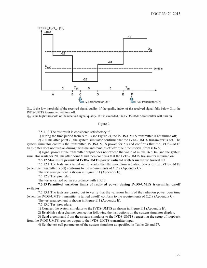
ГОСТ 33470-2015
29
Qout is the low threshold of the received signal quality. If the quality index of the received signal falls below Qout, the IVDS-UMTS transmitter will turn off. Qin is the hight threshold of the received signal quality. If it is exceeded, the IVDS-UMTS transmitter will turn on.
Figure 2
7.5.11.3 The test result is considered satisfactory if: 1) during the time period from A to B (see Figure 2), the IVDS-UMTS transmitter is not turned off; 2) 200 ms after point B, the system simulator confirms that the IVDS-UMTS transmitter is off. The
system simulator controls the transmitted IVDS-UMTS power for 5 s and confirms that the IVDS-UMTS transmitter does not turn on during this time and remains off over the time interval from B to E;
3) signal power at the transmitter output does not exceed the value of minus 56 dBm, and the system simulator waits for 200 ms after point E and then confirms that the IVDS-UMTS transmitter is turned on.
7.5.12 Maximum permitted IVDS-UMTS power radiated with transmitter turned off 7.5.12.1 The tests are carried out to verify that the maximum radiation power of the IVDS-UMTS
(when the transmitter is off) conforms to the requirements of C.2.7 (Appendix C). The test arrangement is shown in Figure E.1 (Appendix E). 7.5.12.2 Test procedure The test is carried out in accordance with 7.5.13. 7.5.13 Permitted variation limits of radiated power during IVDS-UMTS transmitter on/off
switches 7.5.13.1 The tests are carried out to verify that the variation limits of the radiation power over time
(when the IVDS-UMTS transmitter is turned on/off) conform to the requirements of C.2.8 (Appendix C). The test arrangement is shown in Figure E.1 (Appendix E). 7.5.13.2 Test procedure: 1) Connect the system simulator to the IVDS-UMTS as shown in Figure E.1 (Appendix E). 2) Establish a data channel connection following the instructions on the system simulator display. 3) Send a command from the system simulator to the IVDS-UMTS requesting the setup of loopback
from the IVDS-UMTS receiver output to the IVDS-UMTS transmitter input. 4) Set the test cell parameters of the system simulator as specified in Tables 26 and 27.
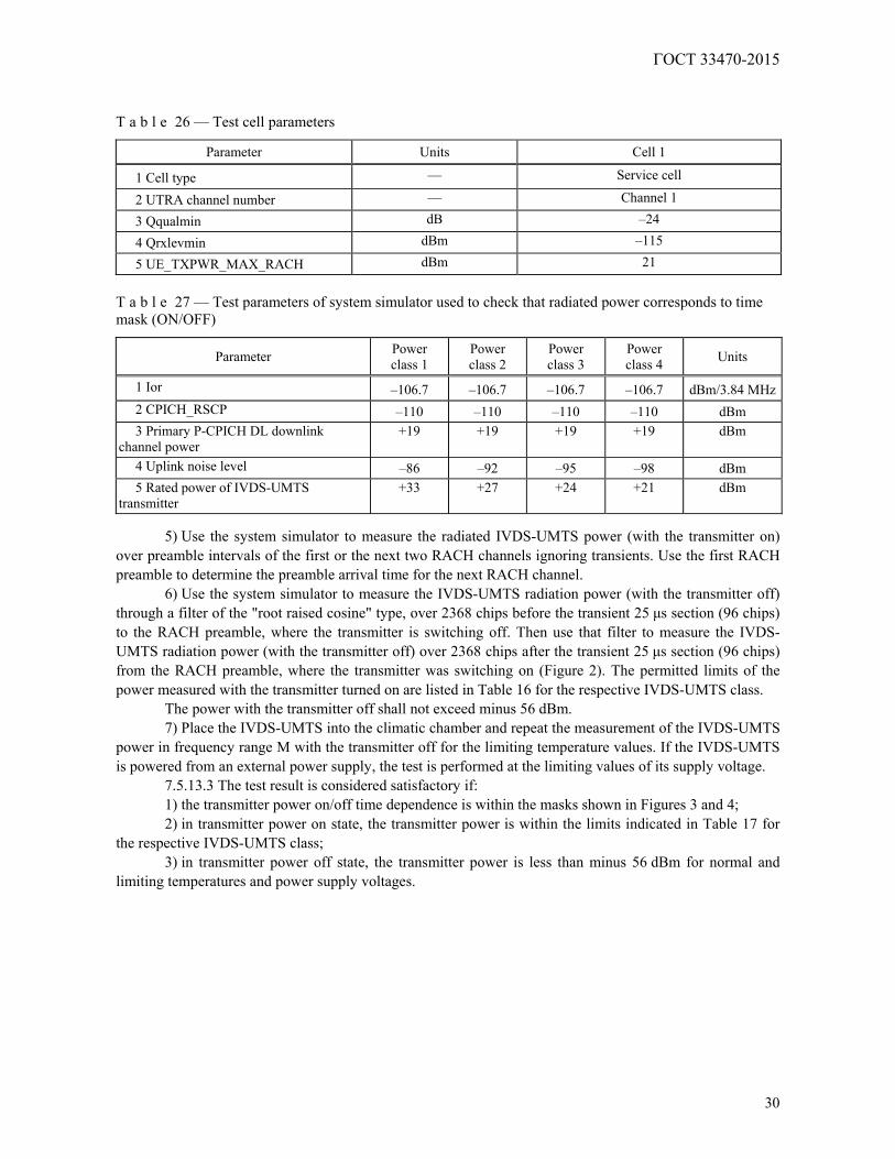
ГОСТ 33470-2015
30
T a b l e 26 — Test cell parameters
Parameter Units Cell 1
1 Cell type — Service cell
2 UTRA channel number — Channel 1
3 Qqualmin dB –24
4 Qrxlevmin dBm –115
5 UE_TXPWR_MAX_RACH dBm 21
T a b l e 27 — Test parameters of system simulator used to check that radiated power corresponds to time mask (ON/OFF)
Parameter Power class 1
Power class 2
Power class 3
Power class 4 Units
1 Ior –106.7 –106.7 –106.7 –106.7 dBm/3.84 MHz2 CPICH_RSCP –110 –110 –110 –110 dBm 3 Primary P-CPICH DL downlink
channel power +19 +19 +19 +19 dBm
4 Uplink noise level –86 –92 –95 –98 dBm 5 Rated power of IVDS-UMTS
transmitter +33 +27 +24 +21 dBm
5) Use the system simulator to measure the radiated IVDS-UMTS power (with the transmitter on)
over preamble intervals of the first or the next two RACH channels ignoring transients. Use the first RACH preamble to determine the preamble arrival time for the next RACH channel.
6) Use the system simulator to measure the IVDS-UMTS radiation power (with the transmitter off) through a filter of the "root raised cosine" type, over 2368 chips before the transient 25 μs section (96 chips) to the RACH preamble, where the transmitter is switching off. Then use that filter to measure the IVDS-UMTS radiation power (with the transmitter off) over 2368 chips after the transient 25 μs section (96 chips) from the RACH preamble, where the transmitter was switching on (Figure 2). The permitted limits of the power measured with the transmitter turned on are listed in Table 16 for the respective IVDS-UMTS class.
The power with the transmitter off shall not exceed minus 56 dBm. 7) Place the IVDS-UMTS into the climatic chamber and repeat the measurement of the IVDS-UMTS
power in frequency range M with the transmitter off for the limiting temperature values. If the IVDS-UMTS is powered from an external power supply, the test is performed at the limiting values of its supply voltage.
7.5.13.3 The test result is considered satisfactory if: 1) the transmitter power on/off time dependence is within the masks shown in Figures 3 and 4; 2) in transmitter power on state, the transmitter power is within the limits indicated in Table 17 for
the respective IVDS-UMTS class; 3) in transmitter power off state, the transmitter power is less than minus 56 dBm for normal and
limiting temperatures and power supply voltages.
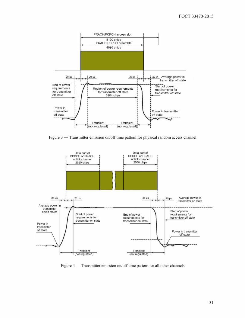
ГОСТ 33470-2015
31
Figure 3 — Transmitter emission on/off time pattern for physical random access channel
Figure 4 — Transmitter emission on/off time pattern for all other channels
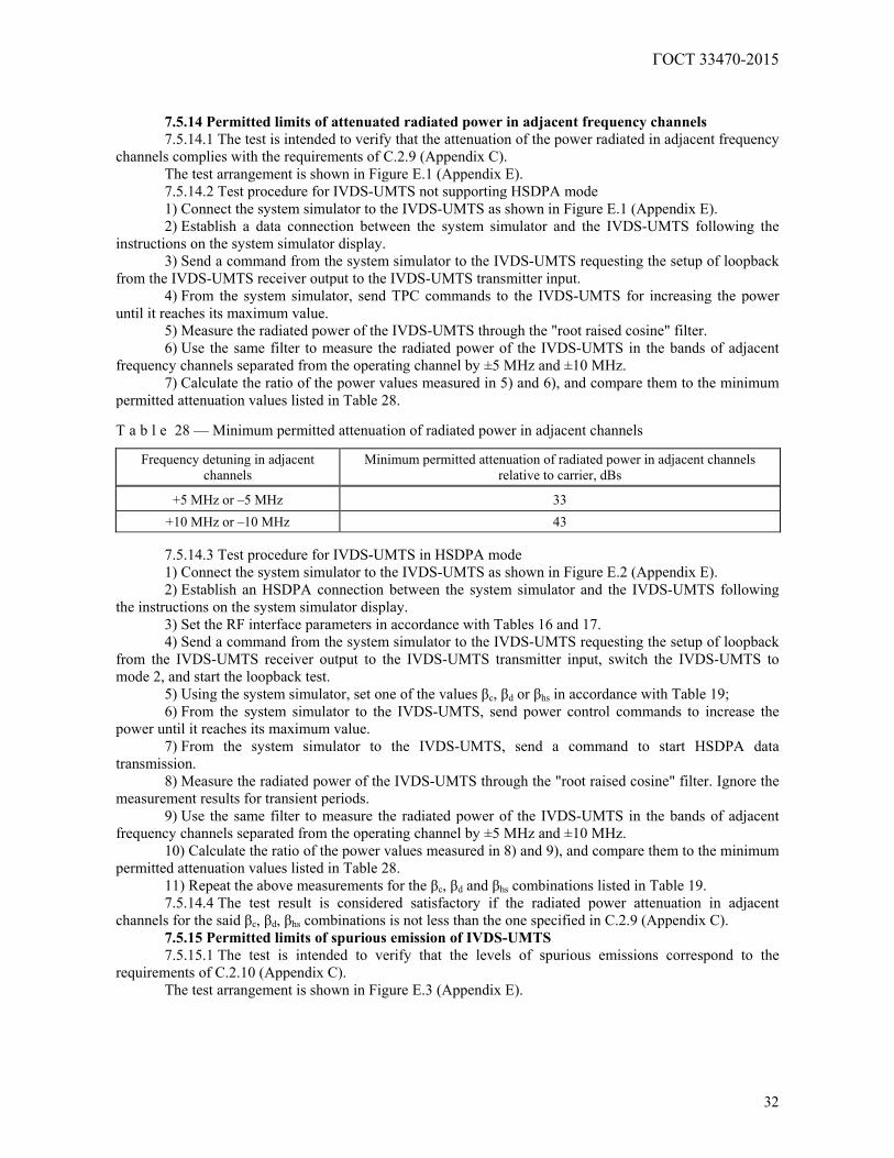
ГОСТ 33470-2015
32
7.5.14 Permitted limits of attenuated radiated power in adjacent frequency channels 7.5.14.1 The test is intended to verify that the attenuation of the power radiated in adjacent frequency
channels complies with the requirements of C.2.9 (Appendix C). The test arrangement is shown in Figure E.1 (Appendix E). 7.5.14.2 Test procedure for IVDS-UMTS not supporting HSDPA mode 1) Connect the system simulator to the IVDS-UMTS as shown in Figure E.1 (Appendix E). 2) Establish a data connection between the system simulator and the IVDS-UMTS following the
instructions on the system simulator display. 3) Send a command from the system simulator to the IVDS-UMTS requesting the setup of loopback
from the IVDS-UMTS receiver output to the IVDS-UMTS transmitter input. 4) From the system simulator, send TPC commands to the IVDS-UMTS for increasing the power
until it reaches its maximum value. 5) Measure the radiated power of the IVDS-UMTS through the "root raised cosine" filter. 6) Use the same filter to measure the radiated power of the IVDS-UMTS in the bands of adjacent
frequency channels separated from the operating channel by ±5 MHz and ±10 MHz. 7) Calculate the ratio of the power values measured in 5) and 6), and compare them to the minimum
permitted attenuation values listed in Table 28. T a b l e 28 — Minimum permitted attenuation of radiated power in adjacent channels
Frequency detuning in adjacent channels
Minimum permitted attenuation of radiated power in adjacent channels relative to carrier, dBs
+5 MHz or –5 MHz 33 +10 MHz or –10 MHz 43
7.5.14.3 Test procedure for IVDS-UMTS in HSDPA mode 1) Connect the system simulator to the IVDS-UMTS as shown in Figure E.2 (Appendix E). 2) Establish an HSDPA connection between the system simulator and the IVDS-UMTS following
the instructions on the system simulator display. 3) Set the RF interface parameters in accordance with Tables 16 and 17. 4) Send a command from the system simulator to the IVDS-UMTS requesting the setup of loopback
from the IVDS-UMTS receiver output to the IVDS-UMTS transmitter input, switch the IVDS-UMTS to mode 2, and start the loopback test.
5) Using the system simulator, set one of the values βс, βd or βhs in accordance with Table 19; 6) From the system simulator to the IVDS-UMTS, send power control commands to increase the
power until it reaches its maximum value. 7) From the system simulator to the IVDS-UMTS, send a command to start HSDPA data
transmission. 8) Measure the radiated power of the IVDS-UMTS through the "root raised cosine" filter. Ignore the
measurement results for transient periods. 9) Use the same filter to measure the radiated power of the IVDS-UMTS in the bands of adjacent
frequency channels separated from the operating channel by ±5 MHz and ±10 MHz. 10) Calculate the ratio of the power values measured in 8) and 9), and compare them to the minimum
permitted attenuation values listed in Table 28. 11) Repeat the above measurements for the βс, βd and βhs combinations listed in Table 19. 7.5.14.4 The test result is considered satisfactory if the radiated power attenuation in adjacent
channels for the said βс, βd, βhs combinations is not less than the one specified in C.2.9 (Appendix C). 7.5.15 Permitted limits of spurious emission of IVDS-UMTS 7.5.15.1 The test is intended to verify that the levels of spurious emissions correspond to the
requirements of C.2.10 (Appendix C). The test arrangement is shown in Figure E.3 (Appendix E).
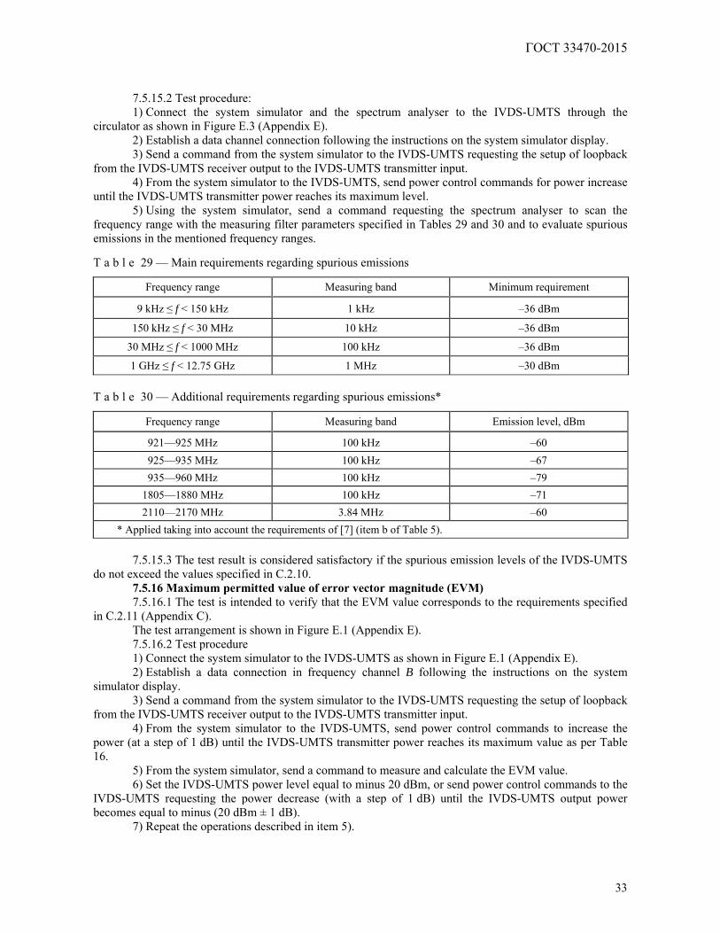
ГОСТ 33470-2015
33
7.5.15.2 Test procedure: 1) Connect the system simulator and the spectrum analyser to the IVDS-UMTS through the
circulator as shown in Figure E.3 (Appendix E). 2) Establish a data channel connection following the instructions on the system simulator display. 3) Send a command from the system simulator to the IVDS-UMTS requesting the setup of loopback
from the IVDS-UMTS receiver output to the IVDS-UMTS transmitter input. 4) From the system simulator to the IVDS-UMTS, send power control commands for power increase
until the IVDS-UMTS transmitter power reaches its maximum level. 5) Using the system simulator, send a command requesting the spectrum analyser to scan the
frequency range with the measuring filter parameters specified in Tables 29 and 30 and to evaluate spurious emissions in the mentioned frequency ranges. T a b l e 29 — Main requirements regarding spurious emissions
Frequency range Measuring band Minimum requirement
9 kHz ≤ f < 150 kHz 1 kHz –36 dBm
150 kHz ≤ f < 30 MHz 10 kHz –36 dBm
30 MHz ≤ f < 1000 MHz 100 kHz –36 dBm
1 GHz ≤ f < 12.75 GHz 1 MHz –30 dBm T a b l e 30 — Additional requirements regarding spurious emissions*
Frequency range Measuring band Emission level, dBm
921—925 MHz 100 kHz –60 925—935 MHz 100 kHz –67 935—960 MHz 100 kHz –79
1805—1880 MHz 100 kHz –71 2110—2170 MHz 3.84 MHz –60
* Applied taking into account the requirements of [7] (item b of Table 5).
7.5.15.3 The test result is considered satisfactory if the spurious emission levels of the IVDS-UMTS do not exceed the values specified in C.2.10.
7.5.16 Maximum permitted value of error vector magnitude (EVM) 7.5.16.1 The test is intended to verify that the EVM value corresponds to the requirements specified
in C.2.11 (Appendix C). The test arrangement is shown in Figure E.1 (Appendix E). 7.5.16.2 Test procedure 1) Connect the system simulator to the IVDS-UMTS as shown in Figure E.1 (Appendix E). 2) Establish a data connection in frequency channel B following the instructions on the system
simulator display. 3) Send a command from the system simulator to the IVDS-UMTS requesting the setup of loopback
from the IVDS-UMTS receiver output to the IVDS-UMTS transmitter input. 4) From the system simulator to the IVDS-UMTS, send power control commands to increase the
power (at a step of 1 dB) until the IVDS-UMTS transmitter power reaches its maximum value as per Table 16.
5) From the system simulator, send a command to measure and calculate the EVM value. 6) Set the IVDS-UMTS power level equal to minus 20 dBm, or send power control commands to the
IVDS-UMTS requesting the power decrease (with a step of 1 dB) until the IVDS-UMTS output power becomes equal to minus (20 dBm ± 1 dB).
7) Repeat the operations described in item 5).
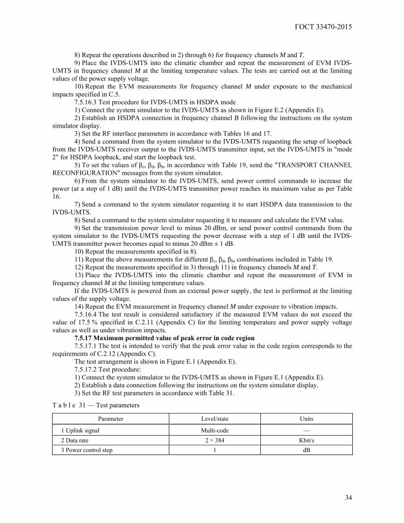
ГОСТ 33470-2015
34
8) Repeat the operations described in 2) through 6) for frequency channels M and T. 9) Place the IVDS-UMTS into the climatic chamber and repeat the measurement of EVM IVDS-
UMTS in frequency channel M at the limiting temperature values. The tests are carried out at the limiting values of the power supply voltage.
10) Repeat the EVM measurements for frequency channel M under exposure to the mechanical impacts specified in C.5.
7.5.16.3 Test procedure for IVDS-UMTS in HSDPA mode 1) Connect the system simulator to the IVDS-UMTS as shown in Figure E.2 (Appendix E). 2) Establish an HSDPA connection in frequency channel B following the instructions on the system
simulator display. 3) Set the RF interface parameters in accordance with Tables 16 and 17. 4) Send a command from the system simulator to the IVDS-UMTS requesting the setup of loopback
from the IVDS-UMTS receiver output to the IVDS-UMTS transmitter input, set the IVDS-UMTS in "mode 2" for HSDPA loopback, and start the loopback test.
5) To set the values of βс, βd, βhs in accordance with Table 19, send the "TRANSPORT CHANNEL RECONFIGURATION" messages from the system simulator.
6) From the system simulator to the IVDS-UMTS, send power control commands to increase the power (at a step of 1 dB) until the IVDS-UMTS transmitter power reaches its maximum value as per Table 16.
7) Send a command to the system simulator requesting it to start HSDPA data transmission to the IVDS-UMTS.
8) Send a command to the system simulator requesting it to measure and calculate the EVM value. 9) Set the transmission power level to minus 20 dBm, or send power control commands from the
system simulator to the IVDS-UMTS requesting the power decrease with a step of 1 dB until the IVDS-UMTS transmitter power becomes equal to minus 20 dBm ± 1 dB.
10) Repeat the measurements specified in 8). 11) Repeat the above measurements for different βс, βd, βhs combinations included in Table 19. 12) Repeat the measurements specified in 3) through 11) in frequency channels M and T. 13) Place the IVDS-UMTS into the climatic chamber and repeat the measurement of EVM in
frequency channel M at the limiting temperature values. If the IVDS-UMTS is powered from an external power supply, the test is performed at the limiting
values of the supply voltage. 14) Repeat the EVM measurement in frequency channel M under exposure to vibration impacts. 7.5.16.4 The test result is considered satisfactory if the measured EVM values do not exceed the
value of 17.5 % specified in C.2.11 (Appendix C) for the limiting temperature and power supply voltage values as well as under vibration impacts.
7.5.17 Maximum permitted value of peak error in code region 7.5.17.1 The test is intended to verify that the peak error value in the code region corresponds to the
requirements of C.2.12 (Appendix C). The test arrangement is shown in Figure E.1 (Appendix E). 7.5.17.2 Test procedure: 1) Connect the system simulator to the IVDS-UMTS as shown in Figure E.1 (Appendix E). 2) Establish a data connection following the instructions on the system simulator display. 3) Set the RF test parameters in accordance with Table 31.
T a b l e 31 — Test parameters
Parameter Level/state Units
1 Uplink signal Multi-code — 2 Data rate 2 × 384 Kbit/s 3 Power control step 1 dB
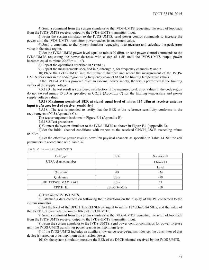
ГОСТ 33470-2015
35
4) Send a command from the system simulator to the IVDS-UMTS requesting the setup of loopback from the IVDS-UMTS receiver output to the IVDS-UMTS transmitter input.
5) From the system simulator to the IVDS-UMTS, send power control commands to increase the power until the IVDS-UMTS transmitter power reaches its maximum value.
6) Send a command to the system simulator requesting it to measure and calculate the peak error value in the code region.
7) Set the IVDS-UMTS power level equal to minus 20 dBm, or send power control commands to the IVDS-UMTS requesting the power decrease with a step of 1 dB until the IVDS-UMTS output power becomes equal to minus 20 dBm ± 1 dB.
8) Repeat the operations described in 5) and 6). 9) Repeat the measurements specified in 5) through 7) for frequency channels M and T. 10) Place the IVDS-UMTS into the climatic chamber and repeat the measurement of the IVDS-
UMTS peak error in the code region using frequency channel M and the limiting temperature values. If the IVDS-UMTS is powered from an external power supply, the test is performed at the limiting
values of the supply voltage. 7.5.17.3 The test result is considered satisfactory if the measured peak error values in the code region
do not exceed minus 15 dB as specified in C.2.12 (Appendix C) for the limiting temperature and power supply voltage values.
7.5.18 Maximum permitted BER at signal equal level of minus 117 dBm at receiver antenna input (reference level of receiver sensitivity)
7.5.18.1 The test is intended to verify that the BER at the reference sensitivity conforms to the requirements of C.3 (Appendix C).
The test arrangement is shown in Figure E.1 (Appendix E). 7.5.18.2 Test procedure: 1) Connect the system simulator to the IVDS-UMTS as shown in Figure E.1 (Appendix E). 2) Set the initial channel conditions with respect to the received CPICH_RSCP exceeding minus
85 dBm. 3) Set the effective power level in downlink physical channels as specified in Table 14. Set the cell
parameters in accordance with Table 32. T a b l e 32 — Cell parameters
Cell type Units Service cell
Channel 1 UTRA channel number —
Level Qqualmin dB -24 Qrxlevmin dBm -79
UE_TXPWR_MAX_RACH dBm 21 CPICH_Еc dBm/3.84 MHz -60
4) Turn on the IVDS-UMTS. 5) Establish a data connection following the instructions on the display of the PC connected to the
system simulator. 6) Set the level of the DPCH_Ec<REFSENS> signal to minus 117 dBm/3.84 MHz, and the value of
the <REF Ior > parameter, to minus 106.7 dBm/3.84 MHz; 7) Send a command from the system simulator to the IVDS-UMTS requesting the setup of loopback
from the IVDS-UMTS receiver output to the IVDS-UMTS transmitter input. 8) From the system simulator to the IVDS-UMTS, send power control commands for power increase
until the IVDS-UMTS transmitter power reaches its maximum level. 9) If the IVDS-UMTS includes an auxiliary low-range receive/transmit device, the transmitter of that
device is turned on at its maximum transmission power. 10) On the system simulator, measure the BER of the DPCH channel received by the IVDS-UMTS.
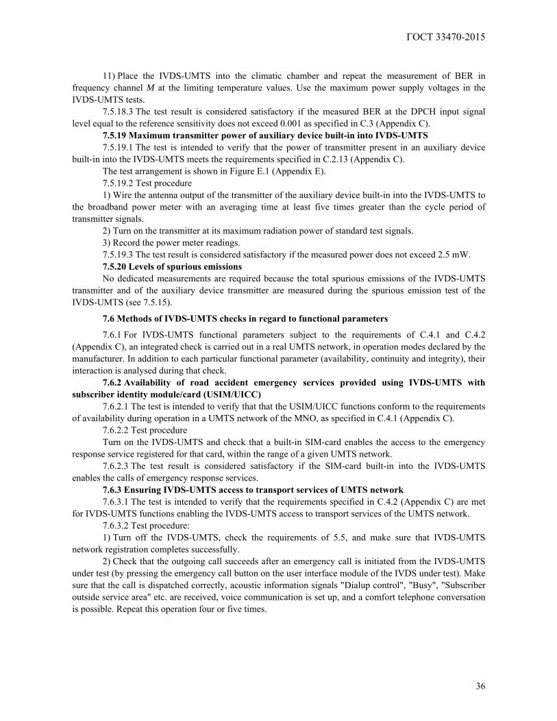
ГОСТ 33470-2015
36
11) Place the IVDS-UMTS into the climatic chamber and repeat the measurement of BER in
frequency channel M at the limiting temperature values. Use the maximum power supply voltages in the IVDS-UMTS tests.
7.5.18.3 The test result is considered satisfactory if the measured BER at the DPCH input signal level equal to the reference sensitivity does not exceed 0.001 as specified in C.3 (Appendix C).
7.5.19 Maximum transmitter power of auxiliary device built-in into IVDS-UMTS 7.5.19.1 The test is intended to verify that the power of transmitter present in an auxiliary device
built-in into the IVDS-UMTS meets the requirements specified in C.2.13 (Appendix C). The test arrangement is shown in Figure E.1 (Appendix E). 7.5.19.2 Test procedure 1) Wire the antenna output of the transmitter of the auxiliary device built-in into the IVDS-UMTS to
the broadband power meter with an averaging time at least five times greater than the cycle period of transmitter signals.
2) Turn on the transmitter at its maximum radiation power of standard test signals. 3) Record the power meter readings. 7.5.19.3 The test result is considered satisfactory if the measured power does not exceed 2.5 mW. 7.5.20 Levels of spurious emissions No dedicated measurements are required because the total spurious emissions of the IVDS-UMTS
transmitter and of the auxiliary device transmitter are measured during the spurious emission test of the IVDS-UMTS (see 7.5.15).
7.6 Methods of IVDS-UMTS checks in regard to functional parameters
7.6.1 For IVDS-UMTS functional parameters subject to the requirements of C.4.1 and C.4.2 (Appendix C), an integrated check is carried out in a real UMTS network, in operation modes declared by the manufacturer. In addition to each particular functional parameter (availability, continuity and integrity), their interaction is analysed during that check.
7.6.2 Availability of road accident emergency services provided using IVDS-UMTS with subscriber identity module/card (USIM/UICC)
7.6.2.1 The test is intended to verify that that the USIM/UICC functions conform to the requirements of availability during operation in a UMTS network of the MNO, as specified in C.4.1 (Appendix C).
7.6.2.2 Test procedure Turn on the IVDS-UMTS and check that a built-in SIM-card enables the access to the emergency
response service registered for that card, within the range of a given UMTS network. 7.6.2.3 The test result is considered satisfactory if the SIM-card built-in into the IVDS-UMTS
enables the calls of emergency response services. 7.6.3 Ensuring IVDS-UMTS access to transport services of UMTS network 7.6.3.1 The test is intended to verify that the requirements specified in C.4.2 (Appendix C) are met
for IVDS-UMTS functions enabling the IVDS-UMTS access to transport services of the UMTS network. 7.6.3.2 Test procedure: 1) Turn off the IVDS-UMTS, check the requirements of 5.5, and make sure that IVDS-UMTS
network registration completes successfully. 2) Check that the outgoing call succeeds after an emergency call is initiated from the IVDS-UMTS
under test (by pressing the emergency call button on the user interface module of the IVDS under test). Make sure that the call is dispatched correctly, acoustic information signals "Dialup control", "Busy", "Subscriber outside service area" etc. are received, voice communication is set up, and a comfort telephone conversation is possible. Repeat this operation four or five times.
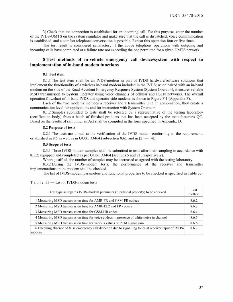
ГОСТ 33470-2015
37
3) Check that the connection is established for an incoming call. For this purpose, enter the number
of the IVDS-UMTS on the system simulator and make sure that the call is dispatched, voice communication is established, and a comfort telephone conversation is possible. Repeat this operation four or five times.
The test result is considered satisfactory if the above telephony operations with outgoing and incoming calls have completed at a failure rate not exceeding the one permitted for a given UMTS network.
8 Test methods of in-vehicle emergency call device/system with respect to
implementation of in-band modem functions 8.1 Test item
8.1.1 The test item shall be an IVDS-modem in part of IVDS hardware/software solutions that implement the functionality of a wireless in-band modem included in the IVDS; when paired with an in-band modem on the side of the Road Accident Emergency Response System (System Operator), it ensures reliable MSD transmission to System Operator using voice channels of cellular and PSTN networks. The overall operation flowchart of in-band IVDS and operator side modems is shown in Figure F.1 (Appendix F).
Each of the two modems includes a receiver and a transmitter unit. In combination, they create a communication level for applications and for interaction with System Operator.
8.1.2 Samples submitted to tests shall be selected by a representative of the testing laboratory (certification body) from a batch of finished products that has been accepted by the manufacturer's QC. Based on the results of sampling, an Act shall be compiled in the form specified in Appendix D.
8.2 Purpose of tests
8.2.1 The tests are aimed at the verification of the IVDS-modem conformity to the requirements established in 8.5 as well as in GOST 33464 (subsection 8.6), and in [2] — [4].
8.3 Scope of tests
8.3.1 Three IVDS-modem samples shall be submitted to tests after their sampling in accordance with 8.1.2, equipped and completed as per GOST 33464 (sections 5 and 21, respectively).
Where justified, the number of samples may be decreased as agreed with the testing laboratory. 8.3.2 During the IVDS-modem tests, the performance of the receiver and transmitter
implementations in the modem shall be checked. The list of IVDS-modem parameters and functional properties to be checked is specified in Table 33.
T a b l e 33 — List of IVDS-modem tests
Test type as regards IVDS-modem parameter (functional property) to be checked Test method
1 Measuring MSD transmission time for AMR-FR and GSM-FR codecs 8.6.2 2 Measuring MSD transmission time for AMR-12.2 and FR codecs 8.6.3 3 Measuring MSD transmission time for GSM-HR codec 8.6.4 4 Measuring MSD transmission time for voice codecs in presence of white noise in channel 8.6.5 5 Measuring MSD transmission time for various values of PCM signal gain 8.6.6 6 Checking absence of false emergency call detection due to signalling tones at receiver input of IVDS-
modem 8.6.7
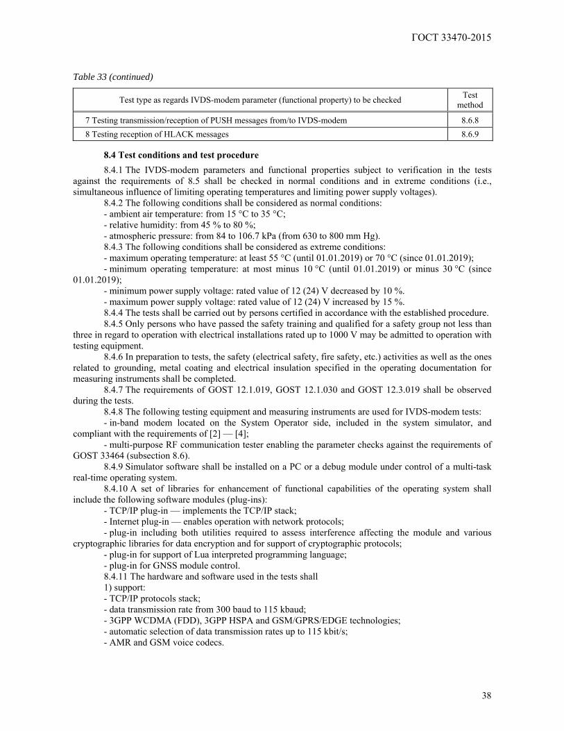
ГОСТ 33470-2015
38
Table 33 (continued)
Test type as regards IVDS-modem parameter (functional property) to be checked Test method
7 Testing transmission/reception of PUSH messages from/to IVDS-modem 8.6.8 8 Testing reception of HLACK messages 8.6.9
8.4 Test conditions and test procedure
8.4.1 The IVDS-modem parameters and functional properties subject to verification in the tests against the requirements of 8.5 shall be checked in normal conditions and in extreme conditions (i.e., simultaneous influence of limiting operating temperatures and limiting power supply voltages).
8.4.2 The following conditions shall be considered as normal conditions: - ambient air temperature: from 15 °С to 35 °С; - relative humidity: from 45 % to 80 %; - atmospheric pressure: from 84 to 106.7 kPa (from 630 to 800 mm Hg). 8.4.3 The following conditions shall be considered as extreme conditions: - maximum operating temperature: at least 55 °C (until 01.01.2019) or 70 °C (since 01.01.2019); - minimum operating temperature: at most minus 10 °C (until 01.01.2019) or minus 30 °C (since
01.01.2019); - minimum power supply voltage: rated value of 12 (24) V decreased by 10 %. - maximum power supply voltage: rated value of 12 (24) V increased by 15 %. 8.4.4 The tests shall be carried out by persons certified in accordance with the established procedure. 8.4.5 Only persons who have passed the safety training and qualified for a safety group not less than
three in regard to operation with electrical installations rated up to 1000 V may be admitted to operation with testing equipment.
8.4.6 In preparation to tests, the safety (electrical safety, fire safety, etc.) activities as well as the ones related to grounding, metal coating and electrical insulation specified in the operating documentation for measuring instruments shall be completed.
8.4.7 The requirements of GOST 12.1.019, GOST 12.1.030 and GOST 12.3.019 shall be observed during the tests.
8.4.8 The following testing equipment and measuring instruments are used for IVDS-modem tests: - in-band modem located on the System Operator side, included in the system simulator, and
compliant with the requirements of [2] — [4]; - multi-purpose RF communication tester enabling the parameter checks against the requirements of
GOST 33464 (subsection 8.6). 8.4.9 Simulator software shall be installed on a PC or a debug module under control of a multi-task
real-time operating system. 8.4.10 A set of libraries for enhancement of functional capabilities of the operating system shall
include the following software modules (plug-ins): - TCP/IP plug-in — implements the TCP/IP stack; - Internet plug-in — enables operation with network protocols; - plug-in including both utilities required to assess interference affecting the module and various
cryptographic libraries for data encryption and for support of cryptographic protocols; - plug-in for support of Lua interpreted programming language; - plug-in for GNSS module control. 8.4.11 The hardware and software used in the tests shall 1) support: - TCP/IP protocols stack; - data transmission rate from 300 baud to 115 kbaud; - 3GPP WCDMA (FDD), 3GPP HSPA and GSM/GPRS/EDGE technologies; - automatic selection of data transmission rates up to 115 kbit/s; - AMR and GSM voice codecs.
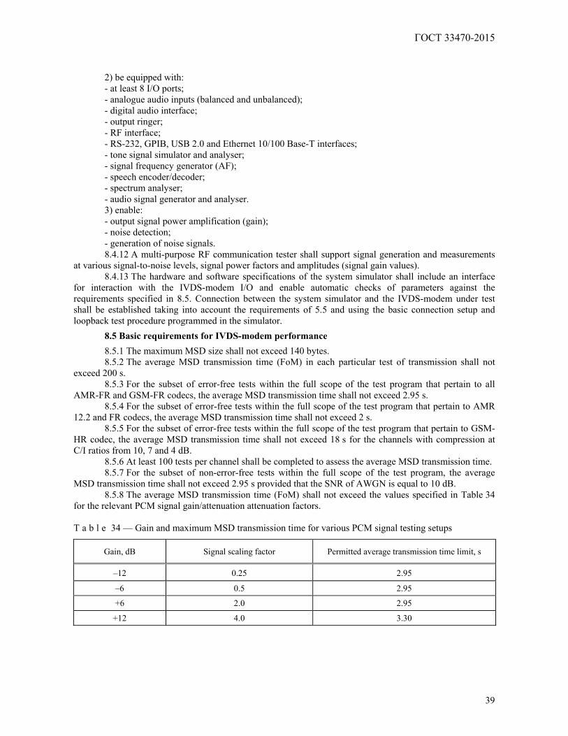
ГОСТ 33470-2015
39
2) be equipped with: - at least 8 I/O ports; - analogue audio inputs (balanced and unbalanced); - digital audio interface; - output ringer; - RF interface; - RS-232, GPIB, USB 2.0 and Ethernet 10/100 Base-T interfaces; - tone signal simulator and analyser; - signal frequency generator (AF); - speech encoder/decoder; - spectrum analyser; - audio signal generator and analyser. 3) enable: - output signal power amplification (gain); - noise detection; - generation of noise signals. 8.4.12 A multi-purpose RF communication tester shall support signal generation and measurements
at various signal-to-noise levels, signal power factors and amplitudes (signal gain values). 8.4.13 The hardware and software specifications of the system simulator shall include an interface
for interaction with the IVDS-modem I/O and enable automatic checks of parameters against the requirements specified in 8.5. Connection between the system simulator and the IVDS-modem under test shall be established taking into account the requirements of 5.5 and using the basic connection setup and loopback test procedure programmed in the simulator.
8.5 Basic requirements for IVDS-modem performance
8.5.1 The maximum MSD size shall not exceed 140 bytes. 8.5.2 The average MSD transmission time (FoM) in each particular test of transmission shall not
exceed 200 s. 8.5.3 For the subset of error-free tests within the full scope of the test program that pertain to all
AMR-FR and GSM-FR codecs, the average MSD transmission time shall not exceed 2.95 s. 8.5.4 For the subset of error-free tests within the full scope of the test program that pertain to AMR
12.2 and FR codecs, the average MSD transmission time shall not exceed 2 s. 8.5.5 For the subset of error-free tests within the full scope of the test program that pertain to GSM-
HR codec, the average MSD transmission time shall not exceed 18 s for the channels with compression at C/I ratios from 10, 7 and 4 dB.
8.5.6 At least 100 tests per channel shall be completed to assess the average MSD transmission time. 8.5.7 For the subset of non-error-free tests within the full scope of the test program, the average
MSD transmission time shall not exceed 2.95 s provided that the SNR of AWGN is equal to 10 dB. 8.5.8 The average MSD transmission time (FoM) shall not exceed the values specified in Table 34
for the relevant PCM signal gain/attenuation attenuation factors. T a b l e 34 — Gain and maximum MSD transmission time for various PCM signal testing setups
Gain, dB Signal scaling factor Permitted average transmission time limit, s
–12 0.25 2.95
–6 0.5 2.95
+6 2.0 2.95
+12 4.0 3.30
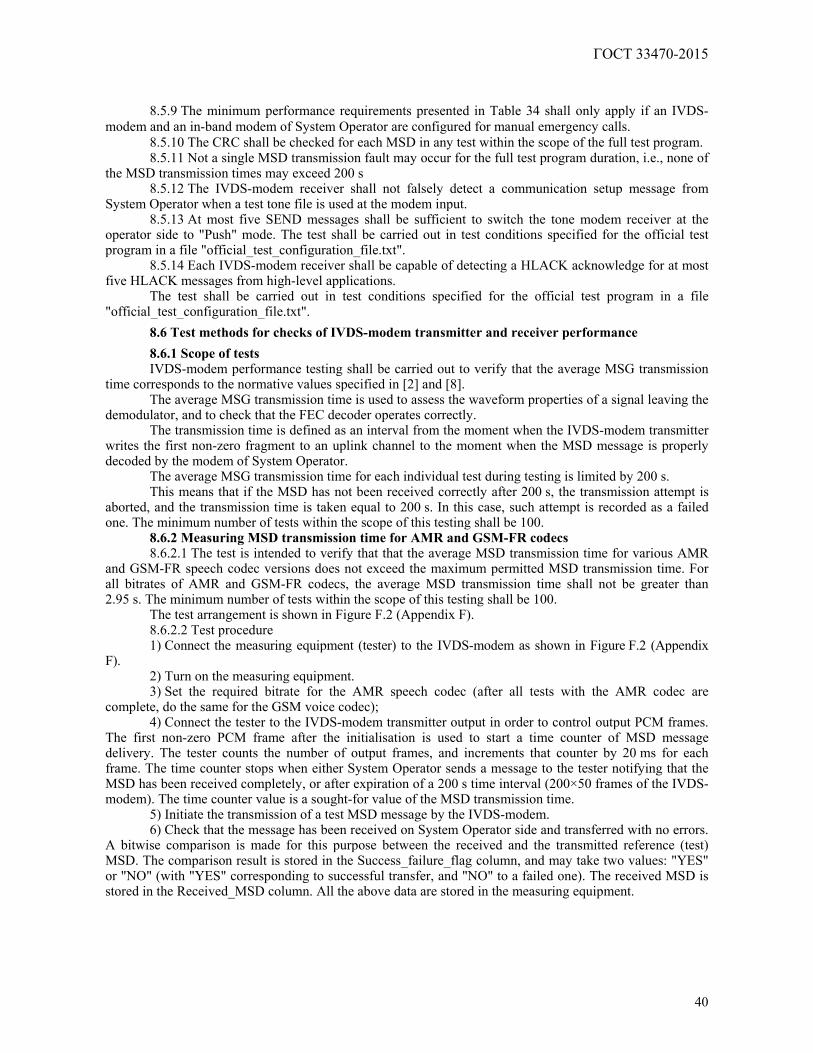
ГОСТ 33470-2015
40
8.5.9 The minimum performance requirements presented in Table 34 shall only apply if an IVDS-
modem and an in-band modem of System Operator are configured for manual emergency calls. 8.5.10 The CRC shall be checked for each MSD in any test within the scope of the full test program. 8.5.11 Not a single MSD transmission fault may occur for the full test program duration, i.e., none of
the MSD transmission times may exceed 200 s 8.5.12 The IVDS-modem receiver shall not falsely detect a communication setup message from
System Operator when a test tone file is used at the modem input. 8.5.13 At most five SEND messages shall be sufficient to switch the tone modem receiver at the
operator side to "Push" mode. The test shall be carried out in test conditions specified for the official test program in a file "official_test_configuration_file.txt".
8.5.14 Each IVDS-modem receiver shall be capable of detecting a HLACK acknowledge for at most five HLACK messages from high-level applications.
The test shall be carried out in test conditions specified for the official test program in a file "official_test_configuration_file.txt".
8.6 Test methods for checks of IVDS-modem transmitter and receiver performance
8.6.1 Scope of tests IVDS-modem performance testing shall be carried out to verify that the average MSG transmission
time corresponds to the normative values specified in [2] and [8]. The average MSG transmission time is used to assess the waveform properties of a signal leaving the
demodulator, and to check that the FEC decoder operates correctly. The transmission time is defined as an interval from the moment when the IVDS-modem transmitter
writes the first non-zero fragment to an uplink channel to the moment when the MSD message is properly decoded by the modem of System Operator.
The average MSG transmission time for each individual test during testing is limited by 200 s. This means that if the MSD has not been received correctly after 200 s, the transmission attempt is
aborted, and the transmission time is taken equal to 200 s. In this case, such attempt is recorded as a failed one. The minimum number of tests within the scope of this testing shall be 100.
8.6.2 Measuring MSD transmission time for AMR and GSM-FR codecs 8.6.2.1 The test is intended to verify that that the average MSD transmission time for various AMR
and GSM-FR speech codec versions does not exceed the maximum permitted MSD transmission time. For all bitrates of AMR and GSM-FR codecs, the average MSD transmission time shall not be greater than 2.95 s. The minimum number of tests within the scope of this testing shall be 100.
The test arrangement is shown in Figure F.2 (Appendix F). 8.6.2.2 Test procedure 1) Connect the measuring equipment (tester) to the IVDS-modem as shown in Figure F.2 (Appendix
F). 2) Turn on the measuring equipment. 3) Set the required bitrate for the AMR speech codec (after all tests with the AMR codec are
complete, do the same for the GSM voice codec); 4) Connect the tester to the IVDS-modem transmitter output in order to control output PCM frames.
The first non-zero PCM frame after the initialisation is used to start a time counter of MSD message delivery. The tester counts the number of output frames, and increments that counter by 20 ms for each frame. The time counter stops when either System Operator sends a message to the tester notifying that the MSD has been received completely, or after expiration of a 200 s time interval (200×50 frames of the IVDS-modem). The time counter value is a sought-for value of the MSD transmission time.
5) Initiate the transmission of a test MSD message by the IVDS-modem. 6) Check that the message has been received on System Operator side and transferred with no errors.
A bitwise comparison is made for this purpose between the received and the transmitted reference (test) MSD. The comparison result is stored in the Success_failure_flag column, and may take two values: "YES" or "NO" (with "YES" corresponding to successful transfer, and "NO" to a failed one). The received MSD is stored in the Received_MSD column. All the above data are stored in the measuring equipment.
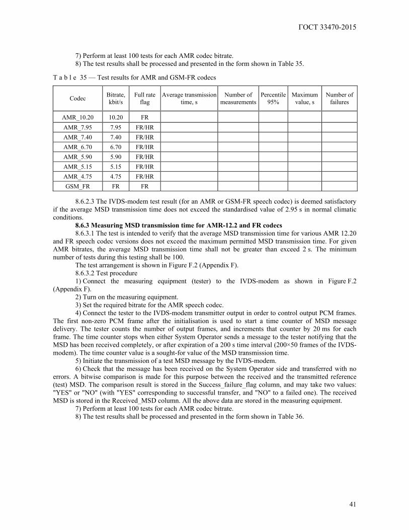
ГОСТ 33470-2015
41
7) Perform at least 100 tests for each AMR codec bitrate. 8) The test results shall be processed and presented in the form shown in Table 35.
T a b l e 35 — Test results for AMR and GSM-FR codecs
Codec Bitrate, kbit/s
Full rate flag
Average transmission time, s
Number of measurements
Percentile 95%
Maximum value, s
Number of failures
AMR_10.20 10.20 FR
AMR_7.95 7.95 FR/HR
AMR_7.40 7.40 FR/HR
AMR_6.70 6.70 FR/HR
AMR_5.90 5.90 FR/HR
AMR_5.15 5.15 FR/HR
AMR_4.75 4.75 FR/HR
GSM_FR FR FR
8.6.2.3 The IVDS-modem test result (for an AMR or GSM-FR speech codec) is deemed satisfactory if the average MSD transmission time does not exceed the standardised value of 2.95 s in normal climatic conditions.
8.6.3 Measuring MSD transmission time for AMR-12.2 and FR codecs 8.6.3.1 The test is intended to verify that the average MSD transmission time for various AMR 12.20
and FR speech codec versions does not exceed the maximum permitted MSD transmission time. For given AMR bitrates, the average MSD transmission time shall not be greater than exceed 2 s. The minimum number of tests during this testing shall be 100.
The test arrangement is shown in Figure F.2 (Appendix F). 8.6.3.2 Test procedure 1) Connect the measuring equipment (tester) to the IVDS-modem as shown in Figure F.2
(Appendix F). 2) Turn on the measuring equipment. 3) Set the required bitrate for the AMR speech codec. 4) Connect the tester to the IVDS-modem transmitter output in order to control output PCM frames.
The first non-zero PCM frame after the initialisation is used to start a time counter of MSD message delivery. The tester counts the number of output frames, and increments that counter by 20 ms for each frame. The time counter stops when either System Operator sends a message to the tester notifying that the MSD has been received completely, or after expiration of a 200 s time interval (200×50 frames of the IVDS-modem). The time counter value is a sought-for value of the MSD transmission time.
5) Initiate the transmission of a test MSD message by the IVDS-modem. 6) Check that the message has been received on the System Operator side and transferred with no
errors. A bitwise comparison is made for this purpose between the received and the transmitted reference (test) MSD. The comparison result is stored in the Success_failure_flag column, and may take two values: "YES" or "NO" (with "YES" corresponding to successful transfer, and "NO" to a failed one). The received MSD is stored in the Received_MSD column. All the above data are stored in the measuring equipment.
7) Perform at least 100 tests for each AMR codec bitrate. 8) The test results shall be processed and presented in the form shown in Table 36.
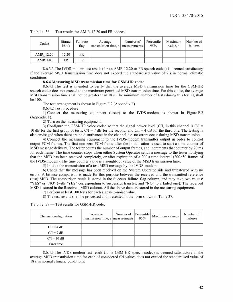
ГОСТ 33470-2015
42
T a b l e 36 — Test results for AM R-12.20 and FR codecs
Codec Bitrate, kbit/s
Full rate flag
Average transmission time, s
Number of measurements
Percentile 95%
Maximum value, s
Number of failures
AMR_12.20 12.20 FR AMR_FR FR FR
8.6.3.3 The IVDS-modem test result (for an AMR 12.20 or FR speech codec) is deemed satisfactory
if the average MSD transmission time does not exceed the standardised value of 2 s in normal climatic conditions.
8.6.4 Measuring MSD transmission time for GSM-HR codec 8.6.4.1 The test is intended to verify that the average MSD transmission time for the GSM-HR
speech codec does not exceed to the maximum permitted MSD transmission time. For this codec, the average MSD transmission time shall not be greater than 18 s. The minimum number of tests during this testing shall be 100.
The test arrangement is shown in Figure F.2 (Appendix F). 8.6.4.2 Test procedure 1) Connect the measuring equipment (tester) to the IVDS-modem as shown in Figure F.2
(Appendix F). 2) Turn on the measuring equipment. 3) Configure the GSM-HR voice codec so that the signal power level (C/I) in this channel is C/I =
10 dB for the first group of tests, C/I = 7 dB for the second, and C/I = 4 dB for the third one. The testing is also envisaged when there are no disturbances in the channel, i.e. no errors occur during MSD transmission.
4) Connect the measuring equipment to the IVDS-modem transmitter output in order to control output PCM frames. The first non-zero PCM frame after the initialisation is used to start a time counter of MSD message delivery. The tester counts the number of output frames, and increments that counter by 20 ms for each frame. The time counter stops when either System Operator sends a message to the tester notifying that the MSD has been received completely, or after expiration of a 200 s time interval (200×50 frames of the IVDS-modem). The time counter value is a sought-for value of the MSD transmission time.
5) Initiate the transmission of a test MSD message by the IVDS-modem. 6) Check that the message has been received on the System Operator side and transferred with no
errors. A bitwise comparison is made for this purpose between the received and the transmitted reference (test) MSD. The comparison result is stored in the Success_failure_flag column, and may take two values: "YES" or "NO" (with "YES" corresponding to successful transfer, and "NO" to a failed one). The received MSD is stored in the Received_MSD column. All the above data are stored in the measuring equipment.
7) Perform at least 100 tests for each signal-to-noise value. 8) The test results shall be processed and presented in the form shown in Table 37.
T a b l e 37 — Test results for GSM-HR codec
Channel configuration Average transmission time, s
Number of measurements
Percentile 95% Maximum value, s Number of
failures
C/I = 4 dB C/I = 7 dB C/l = 10 dB Error free
8.6.4.3 The IVDS-modem test result (for a GSM-HR speech codec) is deemed satisfactory if the
average MSD transmission time for each of considered C/I values does not exceed the standardised value of 18 s in normal climatic conditions.
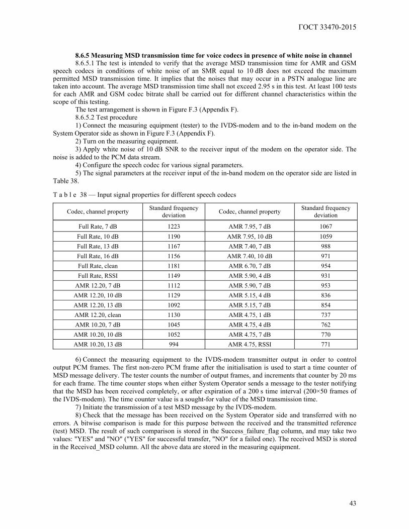
ГОСТ 33470-2015
43
8.6.5 Measuring MSD transmission time for voice codecs in presence of white noise in channel 8.6.5.1 The test is intended to verify that the average MSD transmission time for AMR and GSM
speech codecs in conditions of white noise of an SMR equal to 10 dB does not exceed the maximum permitted MSD transmission time. It implies that the noises that may occur in a PSTN analogue line are taken into account. The average MSD transmission time shall not exceed 2.95 s in this test. At least 100 tests for each AMR and GSM codec bitrate shall be carried out for different channel characteristics within the scope of this testing.
The test arrangement is shown in Figure F.3 (Appendix F). 8.6.5.2 Test procedure 1) Connect the measuring equipment (tester) to the IVDS-modem and to the in-band modem on the
System Operator side as shown in Figure F.3 (Appendix F). 2) Turn on the measuring equipment. 3) Apply white noise of 10 dB SNR to the receiver input of the modem on the operator side. The
noise is added to the PCM data stream. 4) Configure the speech codec for various signal parameters. 5) The signal parameters at the receiver input of the in-band modem on the operator side are listed in
Table 38. T a b l e 38 — Input signal properties for different speech codecs
Codec, channel property Standard frequency deviation Codec, channel property Standard frequency
deviation
Full Rate, 7 dB 1223 AMR 7.95, 7 dB 1067 Full Rate, 10 dB 1190 AMR 7.95, 10 dB 1059 Full Rate, 13 dB 1167 AMR 7.40, 7 dB 988 Full Rate, 16 dB 1156 AMR 7.40, 10 dB 971 Full Rate, clean 1181 AMR 6.70, 7 dB 954 Full Rate, RSSI 1149 AMR 5.90, 4 dB 931
AMR 12.20, 7 dB 1112 AMR 5.90, 7 dB 953 AMR 12.20, 10 dB 1129 AMR 5.15, 4 dB 836 AMR 12.20, 13 dB 1092 AMR 5.15, 7 dB 854 AMR 12.20, clean 1130 AMR 4.75, 1 dB 737 AMR 10.20, 7 dB 1045 AMR 4.75, 4 dB 762 AMR 10.20, 10 dB 1052 AMR 4.75, 7 dB 770 AMR 10.20, 13 dB 994 AMR 4.75, RSSI 771
6) Connect the measuring equipment to the IVDS-modem transmitter output in order to control
output PCM frames. The first non-zero PCM frame after the initialisation is used to start a time counter of MSD message delivery. The tester counts the number of output frames, and increments that counter by 20 ms for each frame. The time counter stops when either System Operator sends a message to the tester notifying that the MSD has been received completely, or after expiration of a 200 s time interval (200×50 frames of the IVDS-modem). The time counter value is a sought-for value of the MSD transmission time.
7) Initiate the transmission of a test MSD message by the IVDS-modem. 8) Check that the message has been received on the System Operator side and transferred with no
errors. A bitwise comparison is made for this purpose between the received and the transmitted reference (test) MSD. The result of such comparison is stored in the Success_failure_flag column, and may take two values: "YES" and "NO" ("YES" for successful transfer, "NO" for a failed one). The received MSD is stored in the Received_MSD column. All the above data are stored in the measuring equipment.

ГОСТ 33470-2015
44
9) Perform at least 100 tests for each speech codec bitrate and different channel parameter values. 10) The test results shall be processed and presented in the form shown in Table 39.
T a b l e 39 — Test results for voice codecs
MSD transmission time, s
White noise, SNR=10 dB Codec, channel property
Average transmission time, s
Percentile95 %
Maximum value, s
Number of measurements
Number of failures
Full Rate, 7 dB
Full Rate, 10 dB
Full Rate, 13 dB
Full Rate, 16 dB
Full Rate, clean
Full Rate, RSSI = –100 dBm
AMR 12.20, 7 dB
AMR 12.20, 10 dB
AMR 12.20, 13 dB
AMR 12.20, clean
AMR 10.20, 7 dB
AMR 10.20, 10 dB
AMR 10.20, 13 dB
AMR 7.95, 7 dB
AMR 7.95, 10 dB
AMR 7.40, 7 dB
AMR 7.40, 10 dB
AMR 6.70, 7 dB
AMR 5.90, 4 dB
AMR 5.90, 7 dB
AMR 5.15, 4 dB
AMR 5.15, 7 dB
AMR 4.75, 1 dB
AMR 4.75, 4 dB
AMR 4.75, 7 dB
AMR 4.75, RSSI = –100 dBm
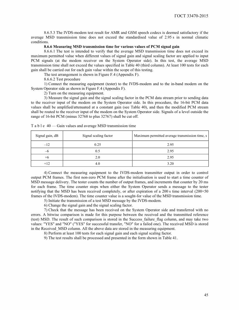
ГОСТ 33470-2015
45
8.6.5.3 The IVDS-modem test result for AMR and GSM speech codecs is deemed satisfactory if the average MSD transmission time does not exceed the standardised value of 2.95 s in normal climatic conditions.
8.6.6 Measuring MSD transmission time for various values of PCM signal gain 8.6.6.1 The test is intended to verify that the average MSD transmission time does not exceed its
maximum permitted value when different values of signal gain and signal scaling factor are applied to input PCM signals (at the modem receiver on the System Operator side). In this test, the average MSD transmission time shall not exceed the values specified in Table 40 (third column). At least 100 tests for each gain shall be carried out for each gain value within the scope of this testing.
The test arrangement is shown in Figure F.4 (Appendix F). 8.6.6.2 Test procedure 1) Connect the measuring equipment (tester) to the IVDS-modem and to the in-band modem on the
System Operator side as shown in Figure F.4 (Appendix F). 2) Turn on the measuring equipment. 3) Measure the signal gain and the signal scaling factor in the PCM data stream prior to sending data
to the receiver input of the modem on the System Operator side. In this procedure, the 16-bit PCM data values shall be amplified/attenuated at a constant gain (see Table 40), and then the modified PCM stream shall be routed to the receiver input of the modem on the System Operator side. Signals of a level outside the range of 16-bit PCM (minus 32768 to plus 32767) shall be cut off. T a b l e 40 — Gain values and average MSD transmission time
Signal gain, dB Signal scaling factor Maximum permitted average transmission time, s
–12 0.25 2.95
–6 0.5 2.95
+6 2.0 2.95
+12 4.0 3.20
4) Connect the measuring equipment to the IVDS-modem transmitter output in order to control output PCM frames. The first non-zero PCM frame after the initialisation is used to start a time counter of MSD message delivery. The tester counts the number of output frames, and increments that counter by 20 ms for each frame. The time counter stops when either the System Operator sends a message to the tester notifying that the MSD has been received completely, or after expiration of a 200 s time interval (200×50 frames of the IVDS-modem). The time counter value is a sought-for value of the MSD transmission time.
5) Initiate the transmission of a test MSD message by the IVDS-modem. 6) Change the signal gain and the signal scaling factor. 7) Check that the message has been received on the System Operator side and transferred with no
errors. A bitwise comparison is made for this purpose between the received and the transmitted reference (test) MSD. The result of such comparison is stored in the Success_failure_flag column, and may take two values: "YES" and "NO" ("YES" for successful transfer, "NO" for a failed one). The received MSD is stored in the Received_MSD column. All the above data are stored in the measuring equipment.
8) Perform at least 100 tests for each signal gain and each signal scaling factor. 9) The test results shall be processed and presented in the form shown in Table 41.
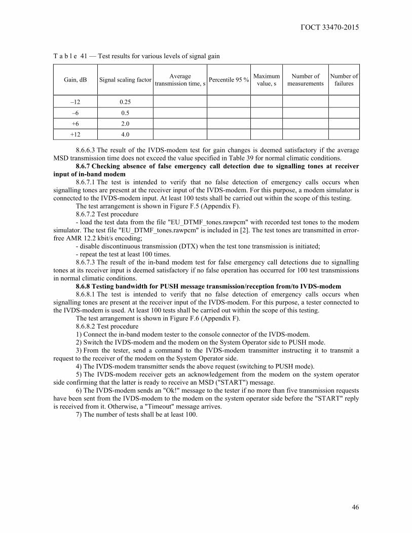
ГОСТ 33470-2015
46
T a b l e 41 — Test results for various levels of signal gain
Gain, dB Signal scaling factor Average transmission time, s Percentile 95 % Maximum
value, s Number of
measurements Number of
failures
–12 0.25
–6 0.5
+6 2.0
+12 4.0
8.6.6.3 The result of the IVDS-modem test for gain changes is deemed satisfactory if the average MSD transmission time does not exceed the value specified in Table 39 for normal climatic conditions.
8.6.7 Checking absence of false emergency call detection due to signalling tones at receiver input of in-band modem
8.6.7.1 The test is intended to verify that no false detection of emergency calls occurs when signalling tones are present at the receiver input of the IVDS-modem. For this purpose, a modem simulator is connected to the IVDS-modem input. At least 100 tests shall be carried out within the scope of this testing.
The test arrangement is shown in Figure F.5 (Appendix F). 8.6.7.2 Test procedure - load the test data from the file "EU_DTMF_tones.rawpcm" with recorded test tones to the modem
simulator. The test file "EU_DTMF_tones.rawpcm" is included in [2]. The test tones are transmitted in error-free AMR 12.2 kbit/s encoding;
- disable discontinuous transmission (DTX) when the test tone transmission is initiated; - repeat the test at least 100 times. 8.6.7.3 The result of the in-band modem test for false emergency call detections due to signalling
tones at its receiver input is deemed satisfactory if no false operation has occurred for 100 test transmissions in normal climatic conditions.
8.6.8 Testing bandwidth for PUSH message transmission/reception from/to IVDS-modem 8.6.8.1 The test is intended to verify that no false detection of emergency calls occurs when
signalling tones are present at the receiver input of the IVDS-modem. For this purpose, a tester connected to the IVDS-modem is used. At least 100 tests shall be carried out within the scope of this testing.
The test arrangement is shown in Figure F.6 (Appendix F). 8.6.8.2 Test procedure 1) Connect the in-band modem tester to the console connector of the IVDS-modem. 2) Switch the IVDS-modem and the modem on the System Operator side to PUSH mode. 3) From the tester, send a command to the IVDS-modem transmitter instructing it to transmit a
request to the receiver of the modem on the System Operator side. 4) The IVDS-modem transmitter sends the above request (switching to PUSH mode). 5) The IVDS-modem receiver gets an acknowledgement from the modem on the system operator
side confirming that the latter is ready to receive an MSD ("START") message. 6) The IVDS-modem sends an "Ok!" message to the tester if no more than five transmission requests
have been sent from the IVDS-modem to the modem on the system operator side before the "START" reply is received from it. Otherwise, a "Timeout" message arrives.
7) The number of tests shall be at least 100.
ГОСТ 33470-2015
47
8.6.8.3 The result of in-band modem bandwidth checks for sending PUSH and receiving PULL
requests is deemed satisfactory if no more than five "START" messages from the IVDS-modem have been received upon the reception of PULL request (i.e., a "START" message) from the modem on the System Operator side, and the IVDS-modem transmitter has not entered standby mode.
8.6.9 Testing reception of HLACK messages 8.6.9.1 The test is intended to verify that the IVDS-modem receiver is able to reliably acquire at most
five HLACK messages from the modem on the System Operator side upon successful MSD transmission. This test is performed for conditions included in the "official_test_configuration_file.txt", using a tester connected to the IVDS-modem. At least 100 tests shall be carried out within the scope of this testing.
The test arrangement is shown in Figure F.7 (Appendix F). 8.6.9.2 Test procedure 1) Connect the in-band modem tester to the console connector of the IVDS-modem. 2) Switch the IVDS-modem and the modem on the System Operator side to PUSH mode. 3) From the tester, send a control command to the IVDS-modem transmitter instructing it to transfer
test files to the receiver of the modem on the System Operator side. 4) The IVDS-modem transmitter sends the test files (MSD message) to the receiver of the modem on
the system operator side. If the MSD is received successfully, the in-band modem on the operator side sends a low level acknowledgement LL-ACK followed by a high level acknowledgement HLACK.
5) The IVDS-modem receiver detects the file reception acknowledgements by analysing the HLACK messages received from the modem on the system operator side.
6) The IVDS-modem sends an "Ok!" message to the tester if no more than five HLACK messages are required for reliable confirmation that the test files have been received. Otherwise, "Timeout" or "Fail" messages arrive.
7) The number of tests shall be at least 100. 8.6.9.3 The result of the in-band modem test for reliable IVDS-modem reception of
acknowledgments from the transmitter of the modem on the system operator side upon successful MSD message transmission is deemed satisfactory if the number of HLACK acknowledgment messages is not greater than five.
9 Checking feasibility of data update on non-removable personal universal
multi-profile subscriber identity card over wireless mobile communication networks 9.1 Test item and test purpose
9.1.1 The test item shall be an IVDS in part of hardware/software solutions that implement its functionality of controlling the profiles on a non-removable personal universal multi-profile subscriber identity card SIM/eUICC included in the wireless communication module of the IVDS.
At least three IVDS samples shall be submitted for the test. 9.1.2 The IVDS samples shall be submitted with an initiated profile of the National System Operator
of the Road Accident Emergency Response System. The information on identification parameters of the SIM/eUICC card (ICCID and IMSI) shall be detailed in the general description of the IVDS type to be provided by the applicant in accordance with the requirements of [1] (section 4, Appendix 12).
9.1.3 The tests are aimed at the verification of the IVDS conformity to the requirements of [1] (clause 118, Appendix 10) in regard to possible data updates on a non-removable personal universal multi-profile subscriber identity card for GSM 900/1800 and UMTS 900/2000 wireless mobile communication networks.
9.2 Test conditions and test procedure 9.2.1 The tests shall be carried out in normal climatic conditions as per 6.4.2 and at a rated power
supply voltage of 12 (24) V.
ГОСТ 33470-2015
48
9.2.2 Checking the feasibility of data updates on the SIM/eUICC card implies that the following test steps involving the operations with an additional profile shall be completed:
- ОТА — downloading additional profile data; - ОТА— initialising and activating the additional profile; - ОТА — controlling (switching) operator profiles; - ОТА — removing the additional profile. 9.2.3 The tests shall be carried out using the system simulator of mobile communication network, or
in a real mobile communication network. The test arrangement using the system simulator is shown in Figure E.1 (Appendix E). 9.2.4 AT-commands, SMS messages or HTTPS data transfer are used for SIM/eUICC card
interaction with the IVDS processor (controller) depending on the data control mechanisms implemented by the SIM/eUICC card manufacturers.
The list and description of AT-commands for SIM/eUICC cards and the recommended techniques of remote downloading of additional profiles shall be included in the operating documentation for the IVDS.
9.3 The methods recommended for checks of IVDS capabilities in regard to remote software updates on SIM/eUICC cards are detailed in Appendix G.
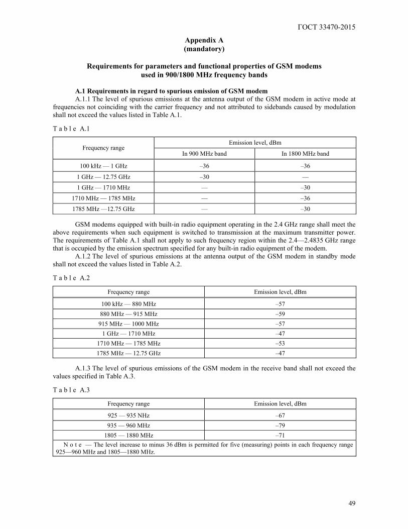
ГОСТ 33470-2015
49
Appendix А (mandatory)
Requirements for parameters and functional properties of GSM modems
used in 900/1800 MHz frequency bands
A.1 Requirements in regard to spurious emission of GSM modem A.1.1 The level of spurious emissions at the antenna output of the GSM modem in active mode at
frequencies not coinciding with the carrier frequency and not attributed to sidebands caused by modulation shall not exceed the values listed in Table A.1. T a b l e A.1
Emission level, dBm Frequency range
In 900 MHz band In 1800 MHz band
100 kHz — 1 GHz –36 –36
1 GHz — 12.75 GHz –30 —
1 GHz — 1710 MHz — –30
1710 MHz — 1785 MHz — –36
1785 MHz —12.75 GHz — –30
GSM modems equipped with built-in radio equipment operating in the 2.4 GHz range shall meet the above requirements when such equipment is switched to transmission at the maximum transmitter power. The requirements of Table A.1 shall not apply to such frequency region within the 2.4—2.4835 GHz range that is occupied by the emission spectrum specified for any built-in radio equipment of the modem.
A.1.2 The level of spurious emissions at the antenna output of the GSM modem in standby mode shall not exceed the values listed in Table A.2. T a b l e A.2
Frequency range Emission level, dBm
100 kHz — 880 MHz –57 880 MHz — 915 MHz –59 915 MHz — 1000 MHz –57
1 GHz — 1710 MHz –47 1710 MHz — 1785 MHz –53 1785 MHz — 12.75 GHz –47
A.1.3 The level of spurious emissions of the GSM modem in the receive band shall not exceed the
values specified in Table A.3. T a b l e A.3
Frequency range Emission level, dBm
925 — 935 NHz –67 935 — 960 MHz –79
1805 — 1880 MHz –71 N o t e — The level increase to minus 36 dBm is permitted for five (measuring) points in each frequency range
925—960 MHz and 1805—1880 MHz.

ГОСТ 33470-2015
50
GSM modems equipped with built-in radio equipment operating in the 2.4 GHz range shall meet the
above requirements when such equipment is switched to transmission at the maximum transmitter power. A.1.4 The level of GSM modem emissions through the body at frequencies not coinciding with the
carrier frequency and not attributed to sidebands caused by modulation shall not exceed the values specified in Tables A.4 and A.5. T a b l e A.4 — Level of emissions through GSM modem body in active mode
Emission level, dBm Frequency range
GSM 900 GSM 1800
30 MHz — 1 GHz –36 –36 1 GHz — 4 GHz –30 —
1 GHz —1710 MHz — –30 1710 MHz — 1785 MHz — –36
1785 MHz — 4 GHz — –30
GSM modems equipped with built-in radio equipment operating in the 2.4 GHz range shall meet the above requirements when such equipment is switched to transmission at the maximum transmitter power. T a b l e A.5 — Level of emissions through GSM modem body in standby mode
Frequency range Emission level, dBm
30 MHz — 880 MHz –57 880 MHz — 915 MHz –59 915 MHz — 1000 MHz –57
1 GHz — 1710 MHz –47 1710 MHz — 1785 MHz –53
1785 MHz — 4 GHz –47
A.2 Requirements for frequencies and phases in static RF channel of GSM modem
A.2.1 The carrier frequency error of the GSM modem transmitter relative to the frequency of the signal received from the base station, or relative to the rated carrier frequency of the channel in normal and extreme conditions shall be at most 0.1·10–6.
A.2.2 The r.m.s. phase error (difference between the phase error path and its linear regression over the useful part of the slot) in normal and extreme conditions shall note exceed 5° for each packet.
A.2.3 The maximum peak phase error over the useful part of each packet in normal and extreme conditions shall be at most 20°.
A.3 Requirements for out-of-band emissions of GSM modem due to modulation
A.3.1 The relative levels of out-of-band emissions that occur due to modulation at the antenna output of the GSM modem in active mode are specified in Tables A.6 and A.7. T a b l e A.6 — Relative levels of out-of-band emissions due to modulation for GSM modems operating in 900 MHz frequency band
Maximum levels of spectral components, dB, w.r.t. level measured in 30 kHz frequency band at carrier frequency vs. frequency detuning, kHz Power level of
GSM modem, dBm 100 200 250 400 600—1800 1800—3000 3000—6000 above 6000
≥ 39 +0.5 –30 –33 –60 –66 –69 –71 –77 37 +0.5 –30 –33 –60 –64 –67 –69 –75
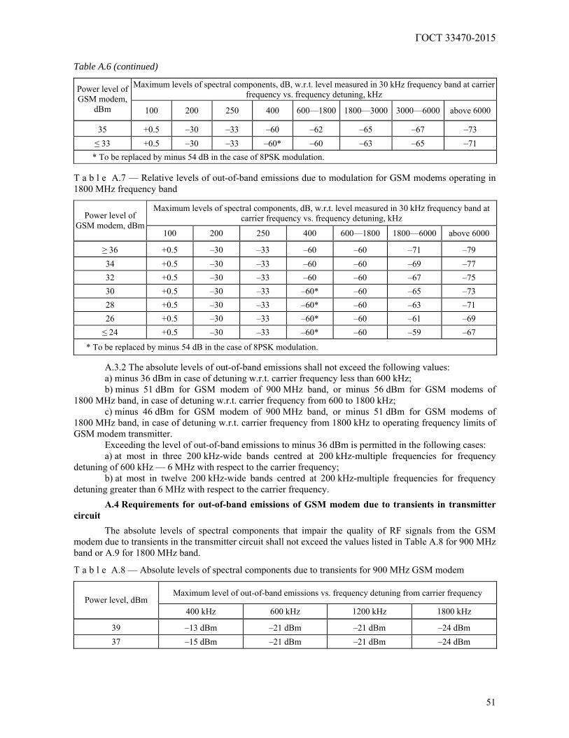
ГОСТ 33470-2015
51
Table A.6 (continued)
Maximum levels of spectral components, dB, w.r.t. level measured in 30 kHz frequency band at carrier frequency vs. frequency detuning, kHz Power level of
GSM modem, dBm 100 200 250 400 600—1800 1800—3000 3000—6000 above 6000
35 +0.5 –30 –33 –60 –62 –65 –67 –73 ≤ 33 +0.5 –30 –33 –60* –60 –63 –65 –71
* To be replaced by minus 54 dB in the case of 8PSK modulation. T a b l e A.7 — Relative levels of out-of-band emissions due to modulation for GSM modems operating in 1800 MHz frequency band
Maximum levels of spectral components, dB, w.r.t. level measured in 30 kHz frequency band at carrier frequency vs. frequency detuning, kHz Power level of
GSM modem, dBm 100 200 250 400 600—1800 1800—6000 above 6000
≥ 36 +0.5 –30 –33 –60 –60 –71 –79 34 +0.5 –30 –33 –60 –60 –69 –77 32 +0.5 –30 –33 –60 –60 –67 –75 30 +0.5 –30 –33 –60* –60 –65 –73 28 +0.5 –30 –33 –60* –60 –63 –71 26 +0.5 –30 –33 –60* –60 –61 –69 ≤ 24 +0.5 –30 –33 –60* –60 –59 –67
* To be replaced by minus 54 dB in the case of 8PSK modulation.
A.3.2 The absolute levels of out-of-band emissions shall not exceed the following values: a) minus 36 dBm in case of detuning w.r.t. carrier frequency less than 600 kHz; b) minus 51 dBm for GSM modem of 900 MHz band, or minus 56 dBm for GSM modems of
1800 MHz band, in case of detuning w.r.t. carrier frequency from 600 to 1800 kHz; c) minus 46 dBm for GSM modem of 900 MHz band, or minus 51 dBm for GSM modems of
1800 MHz band, in case of detuning w.r.t. carrier frequency from 1800 kHz to operating frequency limits of GSM modem transmitter.
Exceeding the level of out-of-band emissions to minus 36 dBm is permitted in the following cases: a) at most in three 200 kHz-wide bands centred at 200 kHz-multiple frequencies for frequency
detuning of 600 kHz — 6 MHz with respect to the carrier frequency; b) at most in twelve 200 kHz-wide bands centred at 200 kHz-multiple frequencies for frequency
detuning greater than 6 MHz with respect to the carrier frequency.
A.4 Requirements for out-of-band emissions of GSM modem due to transients in transmitter circuit
The absolute levels of spectral components that impair the quality of RF signals from the GSM modem due to transients in the transmitter circuit shall not exceed the values listed in Table A.8 for 900 MHz band or A.9 for 1800 MHz band.
T a b l e A.8 — Absolute levels of spectral components due to transients for 900 MHz GSM modem
Maximum level of out-of-band emissions vs. frequency detuning from carrier frequency Power level, dBm
400 kHz 600 kHz 1200 kHz 1800 kHz
39 –13 dBm –21 dBm –21 dBm –24 dBm 37 –15 dBm –21 dBm –21 dBm –24 dBm
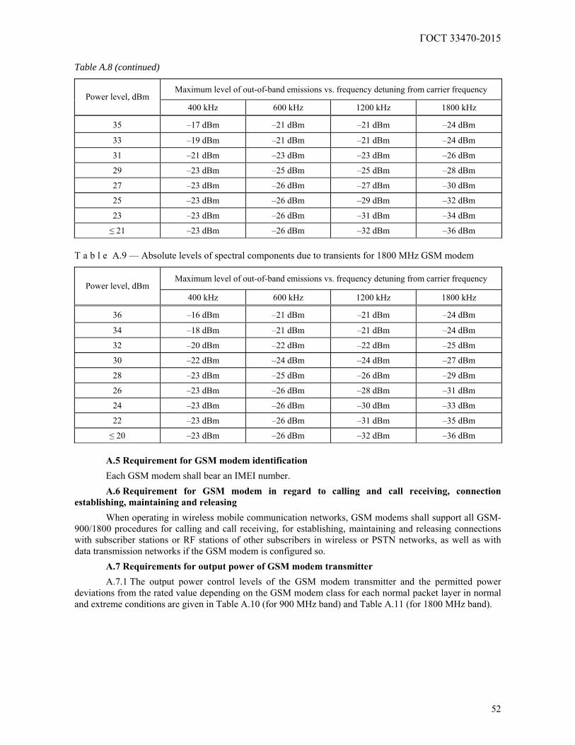
ГОСТ 33470-2015
52
Table A.8 (continued)
Maximum level of out-of-band emissions vs. frequency detuning from carrier frequency Power level, dBm
400 kHz 600 kHz 1200 kHz 1800 kHz
35 –17 dBm –21 dBm –21 dBm –24 dBm
33 –19 dBm –21 dBm –21 dBm –24 dBm
31 –21 dBm –23 dBm –23 dBm –26 dBm
29 –23 dBm –25 dBm –25 dBm –28 dBm
27 –23 dBm –26 dBm –27 dBm –30 dBm
25 –23 dBm –26 dBm –29 dBm –32 dBm
23 –23 dBm –26 dBm –31 dBm –34 dBm
≤ 21 –23 dBm –26 dBm –32 dBm –36 dBm T a b l e A.9 — Absolute levels of spectral components due to transients for 1800 MHz GSM modem
Maximum level of out-of-band emissions vs. frequency detuning from carrier frequency Power level, dBm
400 kHz 600 kHz 1200 kHz 1800 kHz
36 –16 dBm –21 dBm –21 dBm –24 dBm
34 –18 dBm –21 dBm –21 dBm –24 dBm
32 –20 dBm –22 dBm –22 dBm –25 dBm
30 –22 dBm –24 dBm –24 dBm –27 dBm
28 –23 dBm –25 dBm –26 dBm –29 dBm
26 –23 dBm –26 dBm –28 dBm –31 dBm
24 –23 dBm –26 dBm –30 dBm –33 dBm
22 –23 dBm –26 dBm –31 dBm –35 dBm
≤ 20 –23 dBm –26 dBm –32 dBm –36 dBm
A.5 Requirement for GSM modem identification
Each GSM modem shall bear an IMEI number.
A.6 Requirement for GSM modem in regard to calling and call receiving, connection establishing, maintaining and releasing
When operating in wireless mobile communication networks, GSM modems shall support all GSM-900/1800 procedures for calling and call receiving, for establishing, maintaining and releasing connections with subscriber stations or RF stations of other subscribers in wireless or PSTN networks, as well as with data transmission networks if the GSM modem is configured so.
A.7 Requirements for output power of GSM modem transmitter
A.7.1 The output power control levels of the GSM modem transmitter and the permitted power deviations from the rated value depending on the GSM modem class for each normal packet layer in normal and extreme conditions are given in Table A.10 (for 900 MHz band) and Table A.11 (for 1800 MHz band).
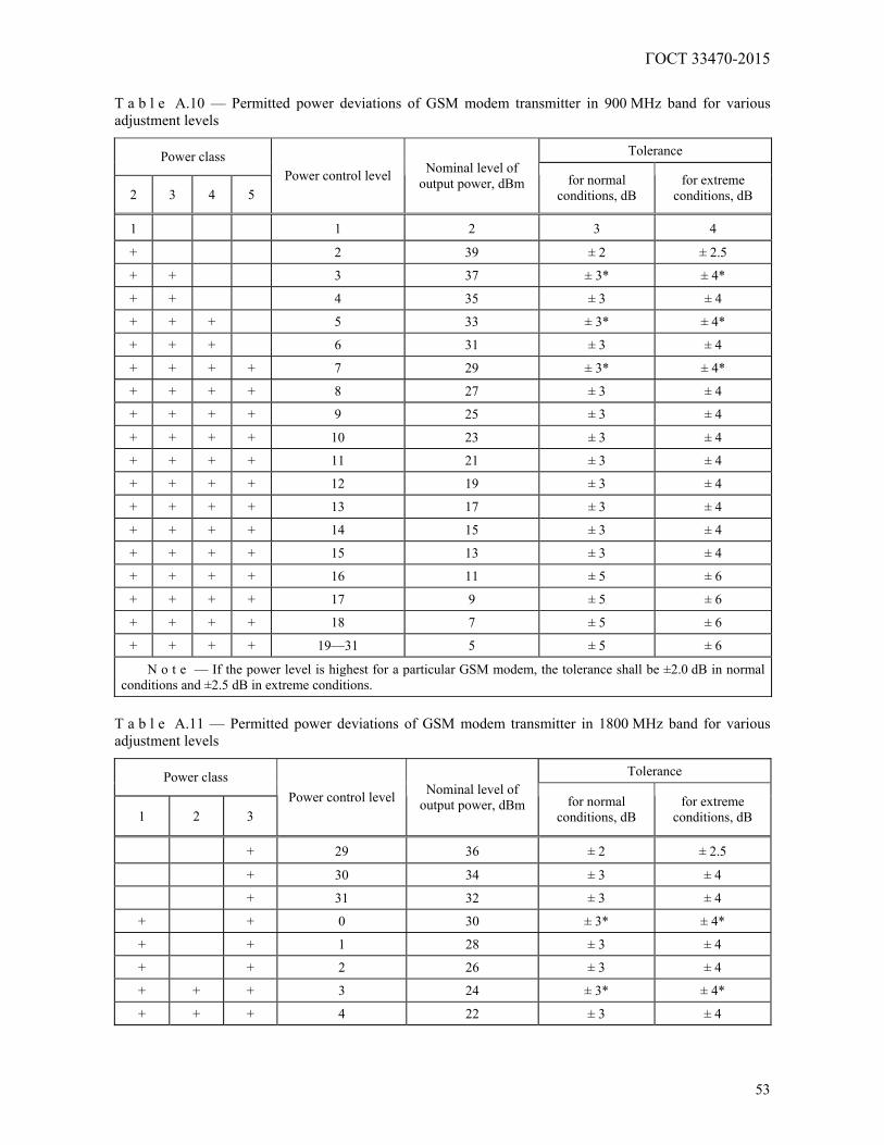
ГОСТ 33470-2015
53
T a b l e A.10 — Permitted power deviations of GSM modem transmitter in 900 MHz band for various adjustment levels
Tolerance Power class
2 3 4 5 Power control level Nominal level of
output power, dBm for normal conditions, dB
for extreme conditions, dB
1 1 2 3 4
+ 2 39 ± 2 ± 2.5
+ + 3 37 ± 3* ± 4*
+ + 4 35 ± 3 ± 4
+ + + 5 33 ± 3* ± 4*
+ + + 6 31 ± 3 ± 4
+ + + + 7 29 ± 3* ± 4*
+ + + + 8 27 ± 3 ± 4
+ + + + 9 25 ± 3 ± 4
+ + + + 10 23 ± 3 ± 4
+ + + + 11 21 ± 3 ± 4
+ + + + 12 19 ± 3 ± 4
+ + + + 13 17 ± 3 ± 4
+ + + + 14 15 ± 3 ± 4
+ + + + 15 13 ± 3 ± 4
+ + + + 16 11 ± 5 ± 6
+ + + + 17 9 ± 5 ± 6
+ + + + 18 7 ± 5 ± 6
+ + + + 19—31 5 ± 5 ± 6
N o t e — If the power level is highest for a particular GSM modem, the tolerance shall be ±2.0 dB in normal conditions and ±2.5 dB in extreme conditions.
T a b l e A.11 — Permitted power deviations of GSM modem transmitter in 1800 MHz band for various adjustment levels
Tolerance Power class
1 2 3 Power control level Nominal level of
output power, dBm for normal conditions, dB
for extreme conditions, dB
+ 29 36 ± 2 ± 2.5
+ 30 34 ± 3 ± 4
+ 31 32 ± 3 ± 4
+ + 0 30 ± 3* ± 4*
+ + 1 28 ± 3 ± 4
+ + 2 26 ± 3 ± 4
+ + + 3 24 ± 3* ± 4*
+ + + 4 22 ± 3 ± 4

ГОСТ 33470-2015
54
Table A.11 (continued)
Tolerance Power class
1 2 3 Power control level Nominal level of
output power, dBm for normal conditions, dB
for extreme conditions, dB
+ + + 5 20 ±3 ±4 + + + 6 18 ±3 ±4 + + + 7 16 ±3 ±4 + + + 8 14 ±3 ±4 + + + 9 12 ±4 ±5 + + + 10 10 ±4 ±5 + + + 11 8 ±4 ±5 + + + 12 6 ±4 ±5 + + + 13 4 ±4 ±5 + + + 14 2 ±5 ±6 + + + 15—28 0 ±5 ±6
N o t e — If the power level is highest for a particular GSM modem, the tolerance shall be ±2.0 dB in normal conditions and ±2.5 dB in extreme conditions.
A.7.2 The values of output power actually radiated by the GSM modem at successive adjustment
levels form a monotonic sequence with intervals of 0.5 to 3.5 dB between those levels. A.7.3 The temporal envelope of the radiated power for normal packets with GMSK modulation shall
be within the pattern shown in Figure A.1.
Figure A.1
The digits marked with "*" in Figure A.1 should be substituted by the following values in the case of the power control levels specified below:
1) for 900 MHz GSM modems: a) for power control level 16: minus 4 dBc; b) for power control level 17: minus 2 dBc; c) for power control levels 18 and 19: minus 1 dBc; 2) for 1800 MHz GSM modems: a) for power control level 11: minus 4 dBc; b) for power control level 12: minus 2 dBc; c) for power control levels 13, 14 and 15: minus 1 dBc. The digits marked with "**" in Figure A.1 should be substituted by the following values: 1) for 900 MHz GSM modems: minus 30 dBc if the absolute level exceeds minus 17 dBm, or minus
17 dBm if the absolute level is less than minus 17 dBm; 2) for 1800 MHz GSM modems: minus 30 dBc if the absolute level exceeds minus 20 dBm, or
minus 20 dBm if the absolute level is less than minus 20 dBm. The lowest levels of the radiated power envelope in Figure A.1 are detailed in Table A.12.
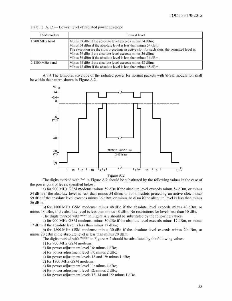
ГОСТ 33470-2015
55
T a b l e A.12 — Lowest level of radiated power envelope
GSM modem Lowest level
1 900 MHz band Minus 59 dBc if the absolute level exceeds minus 54 dBm; Minus 54 dBm if the absolute level is less than minus 54 dBm. The exception are the slots preceding an active slot; for such slots, the permitted level is: Minus 59 dBc if the absolute level exceeds minus 36 dBm; Minus 36 dBm if the absolute level is less than minus 36 dBm.
2 1800 MHz band Minus 48 dBc if the absolute level exceeds minus 48 dBm; Minus 48 dBm if the absolute level is less than minus 48 dBm.
A.7.4 The temporal envelope of the radiated power for normal packets with 8PSK modulation shall
be within the pattern shown in Figure A.2.
Figure A.2
The digits marked with "*" in Figure A.2 should be substituted by the following values in the case of the power control levels specified below:
a) for 900 MHz GSM modems: minus 59 dBc if the absolute level exceeds minus 54 dBm, or minus 54 dBm if the absolute level is less than minus 54 dBm; or for timeslots preceding an active slot: minus 59 dBc if the absolute level exceeds minus 36 dBm, or minus 36 dBm if the absolute level is less than minus 36 dBm;
b) for 1800 MHz GSM modems: minus 48 dBc if the absolute level exceeds minus 48 dBm, or minus 48 dBm, if the absolute level is less than minus 48 dBm. No restrictions for levels less than 30 dBc.
The digits marked with "**" in Figure A.2 should be substituted by the following values: a) for 900 MHz GSM modems: minus 30 dBc if the absolute level exceeds minus 17 dBm, or minus
17 dBm if the absolute level is less than minus 17 dBm; b) for 1800 MHz GSM modems: minus 30 dBc if the absolute level exceeds minus 20 dBm, or
minus 20 dBm if the absolute level is less than minus 20 dBm. The digits marked with "***" in Figure A.2 should be substituted by the following values: 1) for 900 MHz GSM modems: a) for power adjustment level 16: minus 4 dBc; b) for power adjustment level 17: minus 2 dBc; c) for power adjustment levels 18 and 19: minus 1 dBc; 2) for 1800 MHz GSM modems: a) for power adjustment level 11: minus 4 dBc; b) for power adjustment level 12: minus 2 dBc; c) for power adjustment levels 13, 14 and 15: minus 1 dBc.
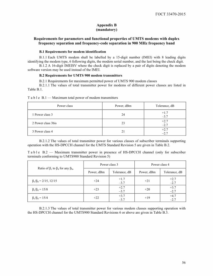
ГОСТ 33470-2015
56
Appendix B (mandatory)
Requirements for parameters and functional properties of UMTS modems with duplex
frequency separation and frequency-code separation in 900 MHz frequency band
B.1 Requirements for modem identification
B.1.1 Each UMTS modem shall be labelled by a 15-digit number (IMEI) with 8 leading digits identifying the modem type, 6 following digits, the modem serial number, and the last being the check digit.
B.1.2 A 16-digit IMEISV where the check digit is replaced by a pair of digits denoting the modem software version may be used instead of the IMEI.
B.2 Requirements for UMTS 900 modem transmitters
B.2.1 Requirements for maximum permitted power of UMTS 900 modem classes B.2.1.1 The values of total transmitter power for modems of different power classes are listed in
Table B.1. T a b l e B.1 — Maximum total power of modem transmitters
Power class Power, dBm Tolerance, dB
1 Power class 3 24 +1.7 –3.7
2 Power class 3bis 23 +2.7 –2.7
3 Power class 4 21 +2.7 –2.7
B.2.1.2 The values of total transmitter power for various classes of subscriber terminals supporting
operation with the HS-DPCCH channel for the UMTS Standard Revision 5 are given in Table B.2. T a b l e B.2 — Maximum transmitter power in presence of HS-DPCCH channel (only for subscriber terminals conforming to UMTS900 Standard Revision 5)
Power class 3 Power class 4 Ratio of βс to βd for any βhs
Power, dBm Tolerance, dB Power, dBm Tolerance, dB
βс/βd = 2/15, 12/15 +24 +1.7 –3.7 +21 +2.7
–2.7
βс/βd = 15/8 +23 +2.7 –3.7 +20 +3.7
–2.7
βс/βd = 15/4 +22 +3.7 –3.7 +19 +4.7
–2.7
B.2.1.3 The values of total transmitter power for various modem classes supporting operation with the HS-DPCCH channel for the UMTS900 Standard Revisions 6 or above are given in Table B.3.
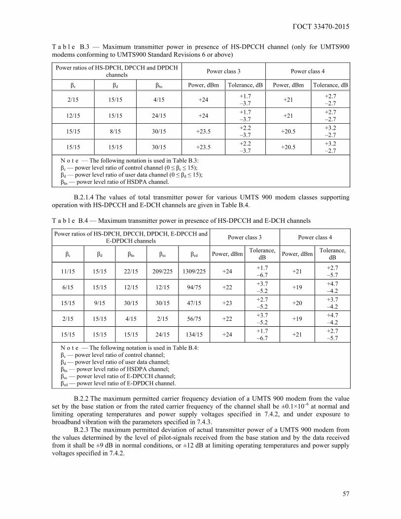
ГОСТ 33470-2015
57
T a b l e B.3 — Maximum transmitter power in presence of HS-DPCCH channel (only for UMTS900 modems conforming to UMTS900 Standard Revisions 6 or above)
Power ratios of HS-DPCH, DPCCH and DPDCH channels Power class 3 Power class 4
βс βd βhs Power, dBm Tolerance, dB Power, dBm Tolerance, dB
2/15 15/15 4/15 +24 +1.7 –3.7 +21 +2.7
–2.7
12/15 15/15 24/15 +24 +1.7 –3.7 +21 +2.7
–2.7
15/15 8/15 30/15 +23.5 +2.2 –3.7 +20.5 +3.2
–2.7
15/15 15/15 30/15 +23.5 +2.2 –3.7 +20.5 +3.2
–2.7 N o t e — The following notation is used in Table B.3: βс — power level ratio of control channel (0 ≤ βс ≤ 15); βd — power level ratio of user data channel (0 ≤ βd ≤ 15); βhs — power level ratio of HSDPA channel.
B.2.1.4 The values of total transmitter power for various UMTS 900 modem classes supporting
operation with HS-DPCCH and E-DCH channels are given in Table B.4. T a b l e B.4 — Maximum transmitter power in presence of HS-DPCCH and E-DCH channels
Power ratios of HS-DPCH, DPCCH, DPDCH, E-DPCCH and E-DPDCH channels Power class 3 Power class 4
βс βd βhs βec βed Power, dBm Tolerance, dB Power, dBm Tolerance,
dB
11/15 15/15 22/15 209/225 1309/225 +24 +1.7 –6.7 +21 +2.7
–5.7
6/15 15/15 12/15 12/15 94/75 +22 +3.7 –5.2 +19 +4.7
–4.2
15/15 9/15 30/15 30/15 47/15 +23 +2.7 –5.2 +20 +3.7
–4.2
2/15 15/15 4/15 2/15 56/75 +22 +3.7 –5.2 +19 +4.7
–4.2
15/15 15/15 15/15 24/15 134/15 +24 +1.7 –6.7 +21 +2.7
–5.7 N o t e — The following notation is used in Table B.4: βс — power level ratio of control channel; βd — power level ratio of user data channel; βhs — power level ratio of HSDPA channel; βec — power level ratio of E-DPCCH channel; βed — power level ratio of E-DPDCH channel.
B.2.2 The maximum permitted carrier frequency deviation of a UMTS 900 modem from the value
set by the base station or from the rated carrier frequency of the channel shall be ±0.1×10⁻⁶ at normal and limiting operating temperatures and power supply voltages specified in 7.4.2, and under exposure to broadband vibration with the parameters specified in 7.4.3.
B.2.3 The maximum permitted deviation of actual transmitter power of a UMTS 900 modem from the values determined by the level of pilot-signals received from the base station and by the data received from it shall be ±9 dB in normal conditions, or ±12 dB at limiting operating temperatures and power supply voltages specified in 7.4.2.
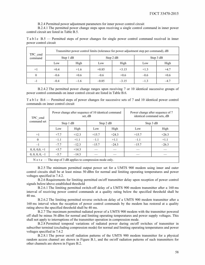
ГОСТ 33470-2015
58
B.2.4 Permitted power adjustment parameters for inner power control circuit B.2.4.1 The permitted power change steps upon receiving a single control command in inner power
control circuit are listed in Table B.5. T a b l e B.5 — Permitted steps of power changes for single power control command received in inner power control circuit
Transmitter power control limits (tolerance for power adjustment step per command), dB
Step 1 dB Step 2 dB Step 3 dB TPC_cmd command
Low High Low High Low High
+1 +0.4 +1.6 +0.85 +3.15 +1.3 +4.7
0 –0.6 +0.6 –0.6 +0.6 –0.6 +0.6
-1 –0.4 –1.6 –0.85 –3.15 –1.3 –4.7
B.2.4.2 The permitted power change ranges upon receiving 7 or 10 identical successive groups of power control commands on inner control circuit are listed in Table B.6. T a b l e B.6 — Permitted steps of power changes for successive sets of 7 and 10 identical power control commands on inner control circuit
Power change after sequence of 10 identical command set, dB
Power change after sequence of 7 identical command sets, dB
Step 1 dB Step 2 dB Step 3 dB
TPC_cmd command set
Low High Low High Low High
+1 +7.7 +12.3 +15.7 +24.3 +15.7 +26.3 0 –1.1 +1.1 –1.1 +1.1 –1.1 +1.1 –1 –7.7 –12.3 –15.7 –24.3 –15.7 –26.3
0, 0, 0,0, +1 +5.7 +14.3 — — — — 0, 0, 0, 0, –1 –5.7 –14.3 — — — —
N o t e — The step of 3 dB applies to compression mode only.
B.2.5 The minimum permitted output power set for a UMTS 900 modem using inner and outer control circuits shall be at least minus 50 dBm for normal and limiting operating temperatures and power voltages specified in 7.4.2.
B.2.6 Requirements for limiting permitted on/off transmitter delay upon reception of power control signals below/above established threshold
B.2.6.1 The limiting permitted switch-off delay of a UMTS 900 modem transmitter after a 160 ms interval of receiving power control commands at a quality rating below the specified threshold shall be 40 ms.
B.2.6.2 The limiting permitted reverse switch-on delay of a UMTS 900 modem transmitter after a 160 ms interval when the reception of power control commands by the modem has restored at a quality rating above the specified threshold shall be 40 ms.
B.2.7 The maximum permitted radiated power of a UMTS 900 modem with the transmitter powered off shall be minus 56 dBm for normal and limiting operating temperatures and power supply voltages. This shall not apply to interruptions of the transmitter operation in compression mode.
B.2.8 Permitted temporal variations of radiated power during on/off switches of transmitter in subscriber terminal (excluding compression mode) for normal and limiting operating temperatures and power voltages specified in 7.4.2
B.2.8.1 The power on/off radiation patterns of the UMTS 900 modem transmitter for a physical random access channel are shown in Figure B.1, and the on/off radiation patterns of such transmitters for other channels are shown in Figure B.2.
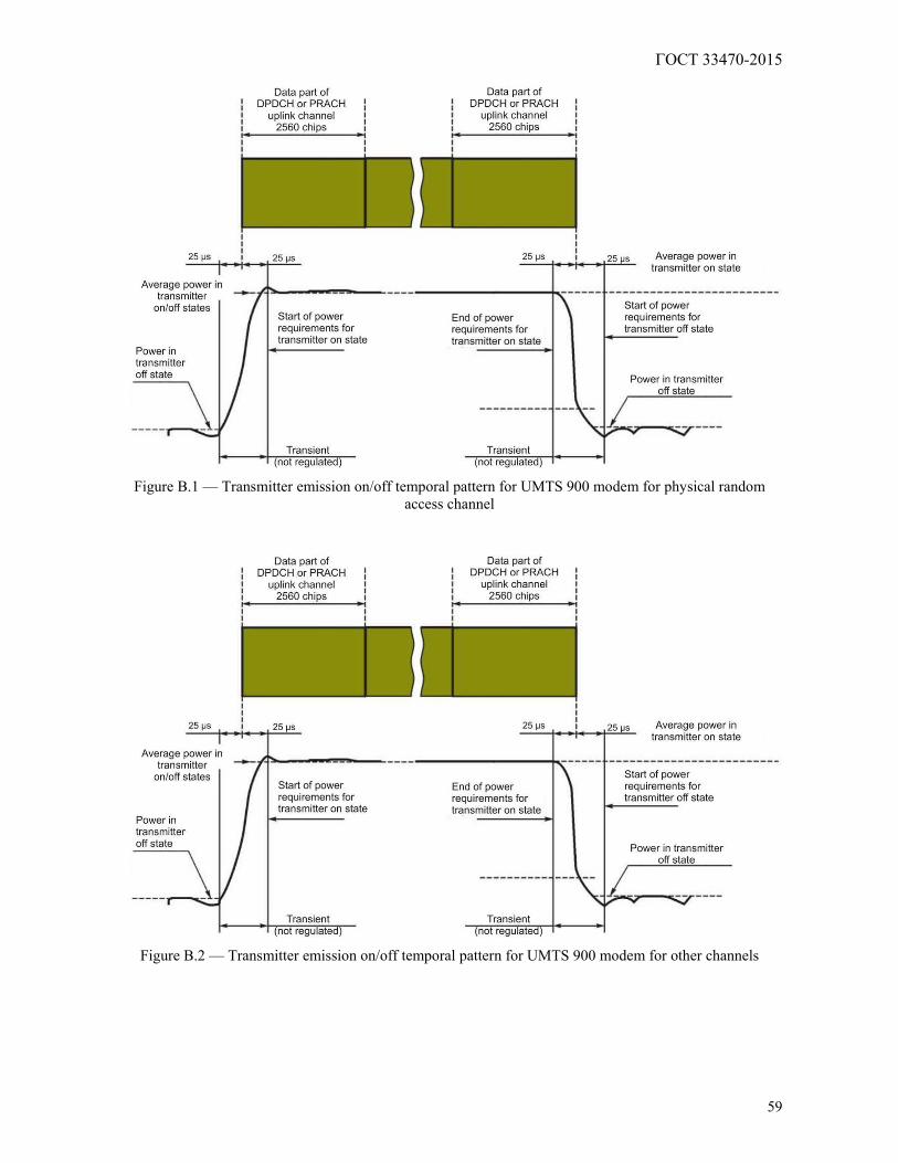
ГОСТ 33470-2015
59
Figure B.1 — Transmitter emission on/off temporal pattern for UMTS 900 modem for physical random
access channel
Figure B.2 — Transmitter emission on/off temporal pattern for UMTS 900 modem for other channels
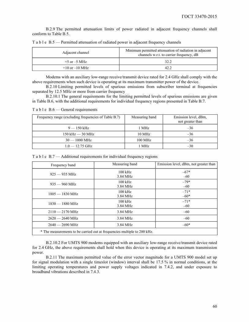
ГОСТ 33470-2015
60
B.2.9 The permitted attenuation limits of power radiated in adjacent frequency channels shall
conform to Table B.5. T a b l e B.5 — Permitted attenuation of radiated power in adjacent frequency channels
Adjacent channel Minimum permitted attenuation of radiation in adjacent channels w.r.t. to carrier frequency, dB
+5 or –5 MHz 32.2 +10 or –10 MHz 42.2
Modems with an auxiliary low-range receive/transmit device rated for 2.4 GHz shall comply with the
above requirements when such device is operating at its maximum transmitter power of the device. B.2.10 Limiting permitted levels of spurious emissions from subscriber terminal at frequencies
separated by 12.5 MHz or more from carrier frequency B.2.10.1 The general requirements for the limiting permitted levels of spurious emissions are given
in Table B.6, with the additional requirements for individual frequency regions presented in Table B.7. T a b l e B.6 — General requirements
Frequency range (excluding frequencies of Table B.7) Measuring band Emission level, dBm, not greater than
9 — 150 kHz 1 MHz –36 150 kHz — 30 MHz 10 MHz –36
30 — 1000 MHz 100 MHz –36 1.0 — 12.75 GHz 1 MHz –30
T a b l e B.7 — Additional requirements for individual frequency regions
Frequency band Measuring band Emission level, dBm, not greater than
925 — 935 MHz 100 kHz 3.84 MHz
–67* –60
935 — 960 MHz 100 kHz 3.84 MHz
–79* –60
1805 — 1830 MHz 100 kHz 3.84 MHz
–71* –60*
1830 — 1880 MHz 100 kHz 3.84 MHz
–71* –60
2110 — 2170 MHz 3.84 MHz –60
2620 — 2640 MHz 3.84 MHz –60
2640 — 2690 MHz 3.84 MHz –60*
* The measurements to be carried out at frequencies multiple to 200 kHz.
B.2.10.2 For UMTS 900 modems equipped with an auxiliary low-range receive/transmit device rated
for 2.4 GHz, the above requirements shall hold when this device is operating at its maximum transmission power.
B.2.11 The maximum permitted value of the error vector magnitude for a UMTS 900 model set up for signal modulation with a single timeslot (window) interval shall be 17.5 % in normal conditions, at the limiting operating temperatures and power supply voltages indicated in 7.4.2, and under exposure to broadband vibrations described in 7.4.3.
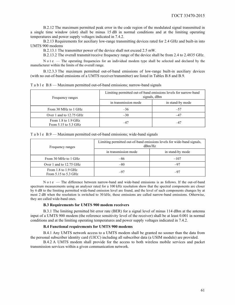
ГОСТ 33470-2015
61
B.2.12 The maximum permitted peak error in the code region of the modulated signal transmitted in
a single time window (slot) shall be minus 15 dB in normal conditions and at the limiting operating temperatures and power supply voltages indicated in 7.4.2.
B.2.13 Requirements for auxiliary low-range transmitting devices rated for 2.4 GHz and built-in into UMTS 900 modems
B.2.13.1 The transmitter power of the device shall not exceed 2.5 mW. B.2.13.2 The overall transmit/receive frequency range of the device shall be from 2.4 to 2.4835 GHz.
N o t e — The operating frequencies for an individual modem type shall be selected and declared by the manufacturer within the limits of the overall range.
B.12.3.3 The maximum permitted out-of-band emissions of low-range built-in auxiliary devices (with no out-of-band emissions of a UMTS receiver/transmitter) are listed in Tables B.8 and B.9. T a b l e B.8 — Maximum permitted out-of-band emissions; narrow-band signals
Limiting permitted out-of-band emissions levels for narrow-band signals, dBm Frequency ranges
in transmission mode in stand-by mode
From 30 MHz to 1 GHz –36 –57 Over 1 and to 12.75 GHz –30 –47
From 1.8 to 1.9 GHz From 5.15 to 5.3 GHz –47 –47
T a b l e B.9 — Maximum permitted out-of-band emissions; wide-band signals
Limiting permitted out-of-band emissions levels for wide-band signals, dBm/Hz Frequency ranges
in transmission mode in stand-by mode
From 30 MHz to 1 GHz –86 –107 Over 1 and to 12.75 GHz –80 –97
From 1.8 to 1.9 GHz From 5.15 to 5.3 GHz –97 –97
N o t e — The difference between narrow-band and wide-band emissions is as follows. If the out-of-band
spectrum measurements using an analyser rated for a 100 kHz resolution show that the spectral components are closer by 6 dB to the limiting permitted wide-band emission level are found, and the level of such components changes by at most 2 dB when the resolution is switched to 30 kHz, these emissions are called narrow-band emissions. Otherwise, they are called wide-band ones.
B.3 Requirements for UMTS 900 modem receivers
B.3.1 The limiting permitted bit error rate (BER) for a signal level of minus 114 dBm at the antenna input of a UMTS 900 modem (the reference sensitivity level of the receiver) shall be at least 0.001 in normal conditions and at the limiting operating temperatures and power supply voltages indicated in 7.4.2.
B.4 Functional requirements for UMTS 900 modems
B.4.1 Any UMTS network access to a UMTS modem shall be granted no sooner than the data from the personal subscriber identity card (UICC) including all subscriber data (a USIM module) are provided.
B.4.2 A UMTS modem shall provide for the access to both wireless mobile services and packet transmission services within a given communication network.
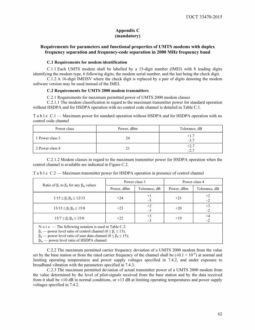
ГОСТ 33470-2015
62
Appendix C (mandatory)
Requirements for parameters and functional properties of UMTS modems with duplex
frequency separation and frequency-code separation in 2000 MHz frequency band
C.1 Requirements for modem identification
C.1.1 Each UMTS modem shall be labelled by a 15-digit number (IMEI) with 8 leading digits identifying the modem type, 6 following digits, the modem serial number, and the last being the check digit.
C.1.2 A 16-digit IMEISV where the check digit is replaced by a pair of digits denoting the modem software version may be used instead of the IMEI.
C.2 Requirements for UMTS 2000 modem transmitters
C.2.1 Requirements for maximum permitted power of UMTS 2000 modem classes C.2.1.1 The modem classification in regard to the maximum transmitter power for standard operation
without HSDPA and for HSDPA operation with no control code channel is detailed in Table C.1. T a b l e C.1 — Maximum power for standard operation without HSDPA and for HSDPA operation with no control code channel
Power class Power, dBm Tolerance, dB
1 Power class 3 24 +1.7 –3.7
2 Power class 4 21 +2.7 –2.7
C.2.1.2 Modem classes in regard to the maximum transmitter power for HSDPA operation when the
control channel is available are indicated in Figure C.2. T a b l e C.2 — Maximum transmitter power for HSDPA operation in presence of control channel
Power class 3 Power class 4 Ratio of βс to βd for any βhs values
Power, dBm Tolerance, dB Power, dBm Tolerance, dB
1/15 ≤ βс/βd ≤ 12/15 +24 +1 –3 +21 +2
–2
13/15 ≤ βс/βd ≤ 15/8 +23 +2 –3 +20 +3
–2
15/7 ≤ βс/βd ≤ 15/0 +22 +3 –3 +19 +4
–2 N o t e — The following notation is used in Table C.2: βс — power level ratio of control channel (0 ≤ βс ≤ 15); βd — power level ratio of user data channel (0 ≤ βd ≤ 15); βhs — power level ratio of HSDPA channel.
C.2.2 The maximum permitted carrier frequency deviation of a UMTS 2000 modem from the value
set by the base station or from the rated carrier frequency of the channel shall be (±0.1 × 10⁻⁶) at normal and limiting operating temperatures and power supply voltages specified in 7.4.2, and under exposure to broadband vibration with the parameters specified in 7.4.3.
C.2.3 The maximum permitted deviation of actual transmitter power of a UMTS 2000 modem from the value determined by the level of pilot-signals received from the base station and by the data received from it shall be ±10 dB in normal conditions, or ±13 dB at limiting operating temperatures and power supply voltages specified in 7.4.2.
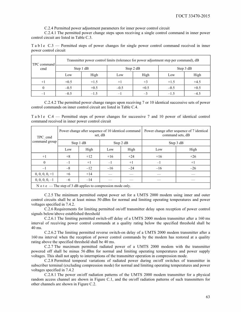
ГОСТ 33470-2015
63
C.2.4 Permitted power adjustment parameters for inner power control circuit C.2.4.1 The permitted power change steps upon receiving a single control command in inner power
control circuit are listed in Table C.3. T a b l e C.3 — Permitted steps of power changes for single power control command received in inner power control circuit
Transmitter power control limits (tolerance for power adjustment step per command), dB
Step 1 dB Step 2 dB Step 3 dB TPC command
cmd
Low High Low High Low High
+1 +0.5 +1.5 +1 +3 +1.5 +4.5 0 –0.5 +0.5 –0.5 +0.5 –0.5 +0.5 –1 –0.5 –1.5 –1 –3 –1.5 –4.5
C.2.4.2 The permitted power change ranges upon receiving 7 or 10 identical successive sets of power
control commands on inner control circuit are listed in Table C.4. T a b l e C.4 — Permitted steps of power changes for successive 7 and 10 power of identical control command received in inner power control circuit
Power change after sequence of 10 identical command set, dB
Power change after sequence of 7 identical command sets, dB
Step 1 dB Step 2 dB Step 3 dB TPC_cmd
command group
Low High Low High Low High
+1 +8 +12 +16 +24 +16 +26 0 –1 +1 –1 +1 –1 +1 –1 –8 –12 –16 –24 –16 –26
0, 0, 0, 0, +1 +6 +14 — — — — 0, 0, 0, 0, –1 –6 –14 — — — — N o t e — The step of 3 dB applies to compression mode only.
C.2.5 The minimum permitted output power set for a UMTS 2000 modem using inner and outer
control circuits shall be at least minus 50 dBm for normal and limiting operating temperatures and power voltages specified in 7.4.2.
C.2.6 Requirements for limiting permitted on/off transmitter delay upon reception of power control signals below/above established threshold
C.2.6.1 The limiting permitted switch-off delay of a UMTS 2000 modem transmitter after a 160 ms interval of receiving power control commands at a quality rating below the specified threshold shall be 40 ms.
C.2.6.2 The limiting permitted reverse switch-on delay of a UMTS 2000 modem transmitter after a 160 ms interval when the reception of power control commands by the modem has restored at a quality rating above the specified threshold shall be 40 ms.
C.2.7 The maximum permitted radiated power of a UMTS 2000 modem with the transmitter powered off shall be minus 56 dBm for normal and limiting operating temperatures and power supply voltages. This shall not apply to interruptions of the transmitter operation in compression mode.
C.2.8 Permitted temporal variations of radiated power during on/off switches of transmitter in subscriber terminal (excluding compression mode) for normal and limiting operating temperatures and power voltages specified in 7.4.2
C.2.8.1 The power on/off radiation patterns of the UMTS 2000 modem transmitter for a physical random access channel are shown in Figure C.1, and the on/off radiation patterns of such transmitters for other channels are shown in Figure C.2.
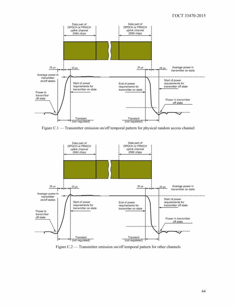
ГОСТ 33470-2015
64
Figure C.1 — Transmitter emission on/off temporal pattern for physical random access channel
Figure C.2 — Transmitter emission on/off temporal pattern for other channels
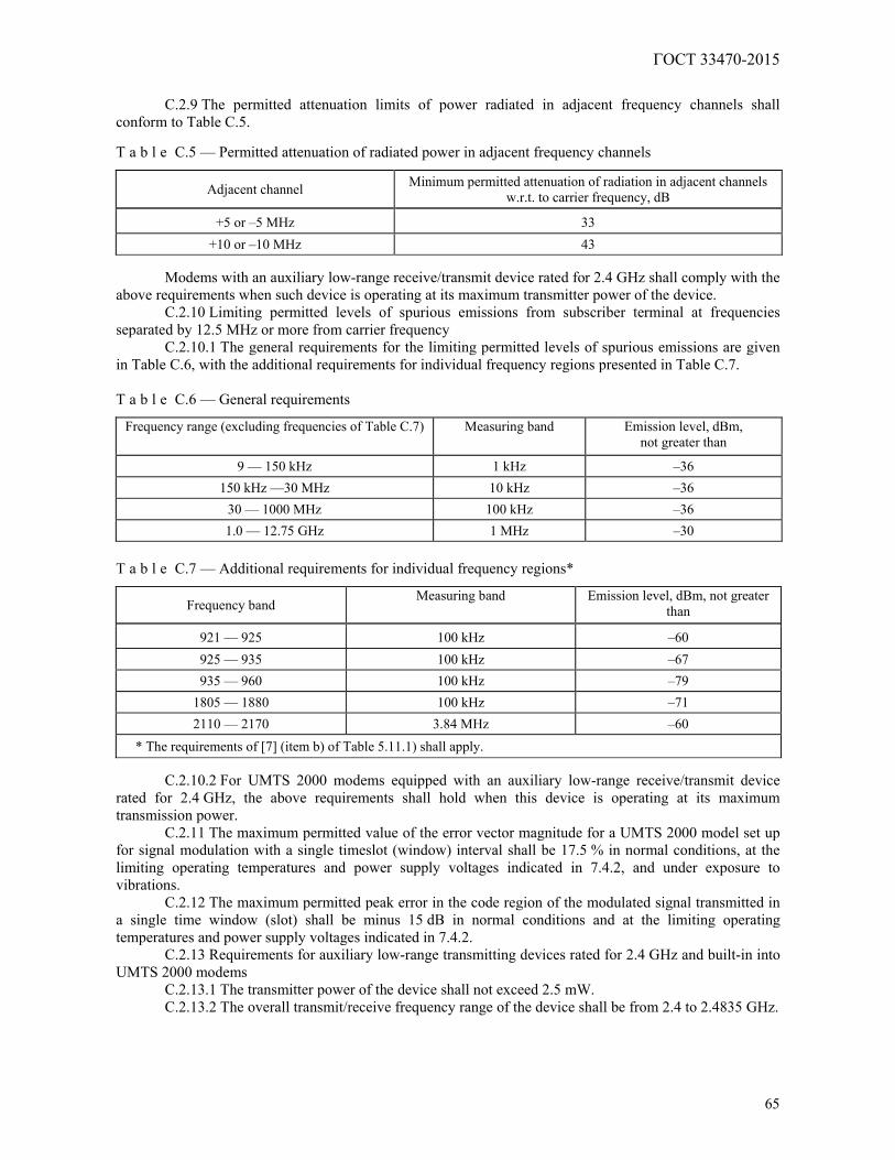
ГОСТ 33470-2015
65
C.2.9 The permitted attenuation limits of power radiated in adjacent frequency channels shall
conform to Table C.5. T a b l e C.5 — Permitted attenuation of radiated power in adjacent frequency channels
Adjacent channel Minimum permitted attenuation of radiation in adjacent channels w.r.t. to carrier frequency, dB
+5 or –5 MHz 33 +10 or –10 MHz 43
Modems with an auxiliary low-range receive/transmit device rated for 2.4 GHz shall comply with the
above requirements when such device is operating at its maximum transmitter power of the device. C.2.10 Limiting permitted levels of spurious emissions from subscriber terminal at frequencies
separated by 12.5 MHz or more from carrier frequency C.2.10.1 The general requirements for the limiting permitted levels of spurious emissions are given
in Table C.6, with the additional requirements for individual frequency regions presented in Table C.7. T a b l e C.6 — General requirements
Frequency range (excluding frequencies of Table C.7) Measuring band Emission level, dBm, not greater than
9 — 150 kHz 1 kHz –36 150 kHz —30 MHz 10 kHz –36
30 — 1000 MHz 100 kHz –36 1.0 — 12.75 GHz 1 MHz –30
T a b l e C.7 — Additional requirements for individual frequency regions*
Frequency band Measuring band Emission level, dBm, not greater
than
921 — 925 100 kHz –60 925 — 935 100 kHz –67 935 — 960 100 kHz –79
1805 — 1880 100 kHz –71 2110 — 2170 3.84 MHz –60
* The requirements of [7] (item b) of Table 5.11.1) shall apply.
C.2.10.2 For UMTS 2000 modems equipped with an auxiliary low-range receive/transmit device rated for 2.4 GHz, the above requirements shall hold when this device is operating at its maximum transmission power.
C.2.11 The maximum permitted value of the error vector magnitude for a UMTS 2000 model set up for signal modulation with a single timeslot (window) interval shall be 17.5 % in normal conditions, at the limiting operating temperatures and power supply voltages indicated in 7.4.2, and under exposure to vibrations.
C.2.12 The maximum permitted peak error in the code region of the modulated signal transmitted in a single time window (slot) shall be minus 15 dB in normal conditions and at the limiting operating temperatures and power supply voltages indicated in 7.4.2.
C.2.13 Requirements for auxiliary low-range transmitting devices rated for 2.4 GHz and built-in into UMTS 2000 modems
C.2.13.1 The transmitter power of the device shall not exceed 2.5 mW. C.2.13.2 The overall transmit/receive frequency range of the device shall be from 2.4 to 2.4835 GHz.
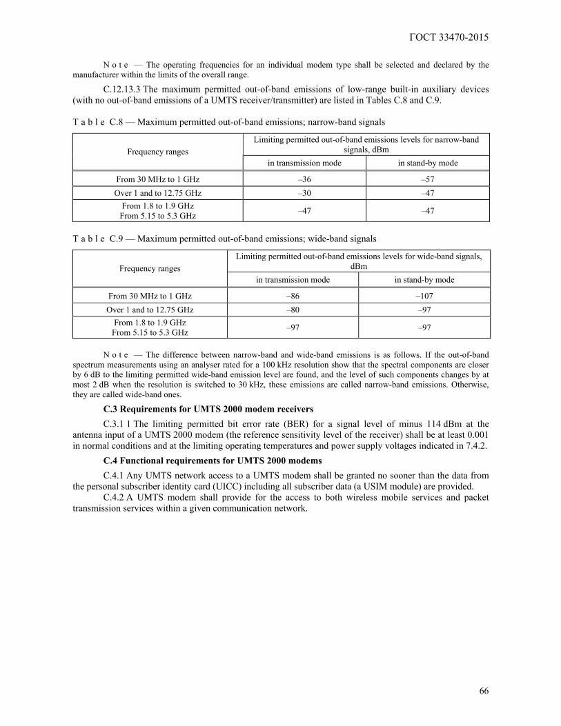
ГОСТ 33470-2015
66
N o t e — The operating frequencies for an individual modem type shall be selected and declared by the
manufacturer within the limits of the overall range.
C.12.13.3 The maximum permitted out-of-band emissions of low-range built-in auxiliary devices (with no out-of-band emissions of a UMTS receiver/transmitter) are listed in Tables C.8 and C.9. T a b l e C.8 — Maximum permitted out-of-band emissions; narrow-band signals
Limiting permitted out-of-band emissions levels for narrow-band signals, dBm Frequency ranges
in transmission mode in stand-by mode
From 30 MHz to 1 GHz –36 –57 Over 1 and to 12.75 GHz –30 –47
From 1.8 to 1.9 GHz From 5.15 to 5.3 GHz –47 –47
T a b l e C.9 — Maximum permitted out-of-band emissions; wide-band signals
Limiting permitted out-of-band emissions levels for wide-band signals, dBm Frequency ranges
in transmission mode in stand-by mode
From 30 MHz to 1 GHz –86 –107 Over 1 and to 12.75 GHz –80 –97
From 1.8 to 1.9 GHz From 5.15 to 5.3 GHz –97 –97
N o t e — The difference between narrow-band and wide-band emissions is as follows. If the out-of-band
spectrum measurements using an analyser rated for a 100 kHz resolution show that the spectral components are closer by 6 dB to the limiting permitted wide-band emission level are found, and the level of such components changes by at most 2 dB when the resolution is switched to 30 kHz, these emissions are called narrow-band emissions. Otherwise, they are called wide-band ones.
C.3 Requirements for UMTS 2000 modem receivers
C.3.1 1 The limiting permitted bit error rate (BER) for a signal level of minus 114 dBm at the antenna input of a UMTS 2000 modem (the reference sensitivity level of the receiver) shall be at least 0.001 in normal conditions and at the limiting operating temperatures and power supply voltages indicated in 7.4.2.
C.4 Functional requirements for UMTS 2000 modems
C.4.1 Any UMTS network access to a UMTS modem shall be granted no sooner than the data from the personal subscriber identity card (UICC) including all subscriber data (a USIM module) are provided.
C.4.2 A UMTS modem shall provide for the access to both wireless mobile services and packet transmission services within a given communication network.
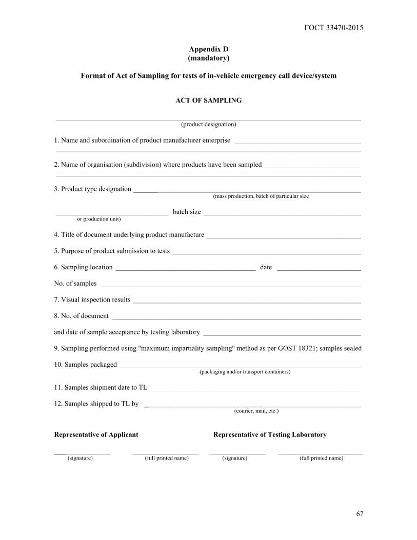
ГОСТ 33470-2015
67
Appendix D (mandatory)
Format of Act of Sampling for tests of in-vehicle emergency call device/system
ACT OF SAMPLING
_______________________________________________________________________________________ (product designation)
1. Name and subordination of product manufacturer enterprise ____________________________________ _______________________________________________________________________________________
2. Name of organisation (subdivision) where products have been sampled ___________________________ _______________________________________________________________________________________
3. Product type designation _________________________________________________________________
(mass production, batch of particular size ________________________________ batch size _____________________________________________
or production unit) 4. Title of document underlying product manufacture ____________________________________________ 5. Purpose of product submission to tests ______________________________________________________ 6. Sampling location ________________________________________ date ________________________ No. of samples __________________________________________________________________________ 7. Visual inspection results _________________________________________________________________ 8. No. of document _______________________________________________________________________ and date of sample acceptance by testing laboratory _____________________________________________ 9. Sampling performed using "maximum impartiality sampling" method as per GOST 18321; samples sealed 10. Samples packaged _____________________________________________________________________
(packaging and/or transport containers) 11. Samples shipment date to TL ____________________________________________________________ 12. Samples shipped to TL by ______________________________________________________________
(courier, mail, etc.) Representative of Applicant Representative of Testing Laboratory ________________ ___________________ ________________ ________________________
(signature) (full printed name) (signature) (full printed name)
ГОСТ 33470-2015
68
Appendix E (mandatory)
Structural flowcharts of test beds and connections for tests of in-vehicle emergency call
device/system in regard to implementation of UMTS modem functions
Figure E.1 — Arrangement for IVDS-UMTS tests using UMTS system simulator
Figure E.2 — Arrangement for IVDS-UMTS tests pertaining to evaluation of maximum output power in HSDPA mode
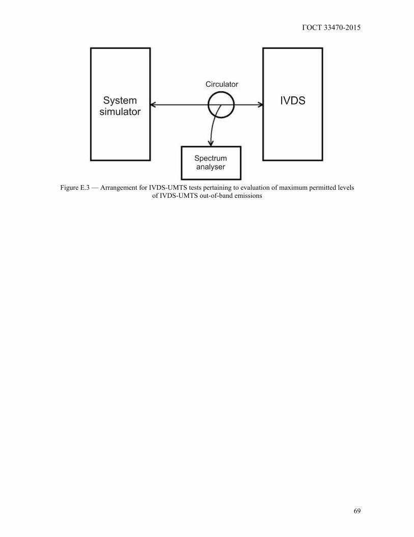
ГОСТ 33470-2015
69
Figure E.3 — Arrangement for IVDS-UMTS tests pertaining to evaluation of maximum permitted levels
of IVDS-UMTS out-of-band emissions

ГОСТ 33470-2015
70
Appendix F (mandatory)
Structural flowcharts of test beds and connections for tests of in-vehicle emergency call
device/system as regards implementation of in-band modem functions
Figure F.1 — General flowchart of in-band modem operation
Figure F.2 — General test arrangement for evaluation of average MSD transfer time
for various AMR and GSM-FR speech codecs
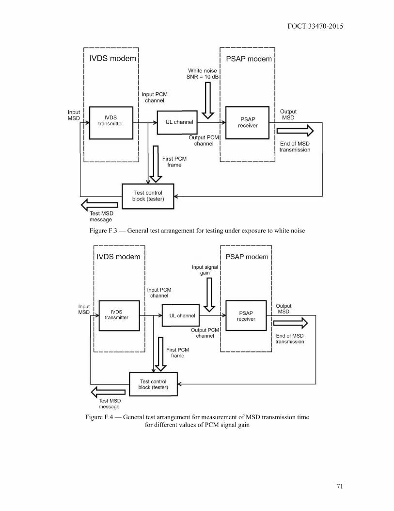
ГОСТ 33470-2015
71
Figure F.3 — General test arrangement for testing under exposure to white noise
Figure F.4 — General test arrangement for measurement of MSD transmission time
for different values of PCM signal gain
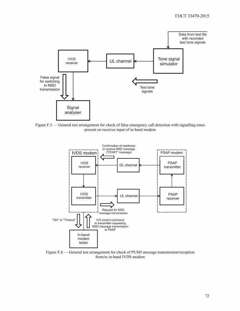
ГОСТ 33470-2015
72
Figure F.5 — General test arrangement for check of false emergency call detection with signalling tones
present on receiver input of in-band modem
Figure F.6 — General test arrangement for check of PUSH message transmission/reception
from/to in-band IVDS modem
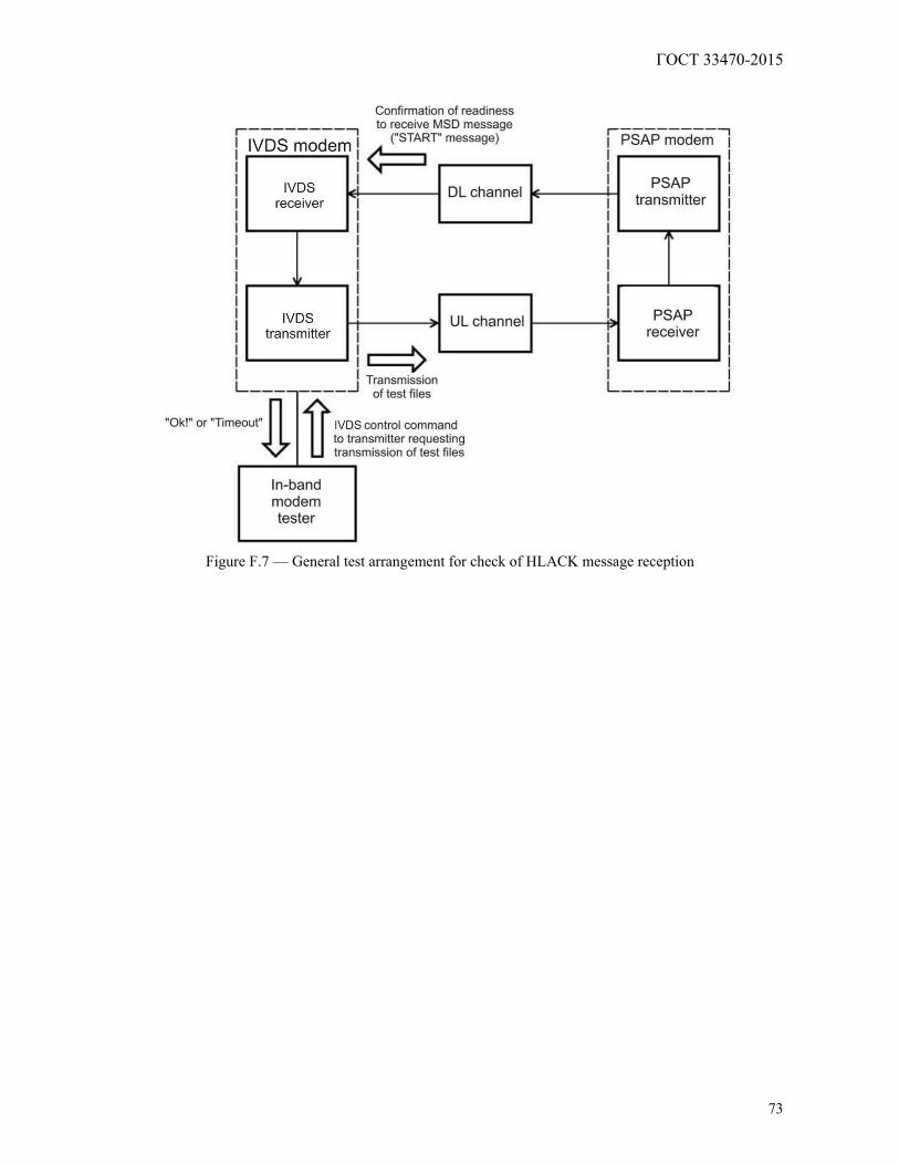
ГОСТ 33470-2015
73
Figure F.7 — General test arrangement for check of HLACK message reception
ГОСТ 33470-2015
74
Appendix G
(recommended)
Test methods of in-vehicle emergency call device/system for check of possible data update on non-removable personal universal multi-profile subscriber identity card over wireless mobile
communication networks
G.1 Checking IVDS capability of remote downloading/removal of additional profile on SIM/eUICC card
G.1.1 The tests are carried out in the arrangement given in Figure E.1 (Appendix E) using the system simulator of mobile communication network, or in a real mobile communication network.
G.1.2 Send the AT-command "Remote downloading of SIM/eUICC card profile data" with a reference profile (ICCID and IMSI) to the IVDS.
G.1.3 Send the AT-command "Read SIM/eUICC card profile data" (ICCID and IMSI) to the IVDS. G.1.4 Compare the values of ICCID and IMSI in the written and read SIM/eUICC card profiles. G.1.5 Send a command to remove the downloaded profile. G.1.6 Repeat the operations of G.1.2 — G.1.5 ten times. G.1.7 The test results are considered positive if no mismatches are found between the read values
(ICCID and IMSI) and the values (ICCID and IMSI) of the reference profile.
G.2 Checking IVDS capability of remote initialisation and activation of additional profile on SIM/eUICC card
G.2.1 The tests are carried out in the arrangement given in Figure E.1 (Appendix E) using the system simulator of mobile communication network, or in a real mobile communication network.
G.2.2 Download a new profile to the SIM/eUICC card. G.2.3 Send a command for activation of the new profile and for reading its ICCID and IMSI data. G.2.4 Compare the ICCID and IMSI values with the reference profile. G.2.5 Using an AT-command, perform a local switch to the initial profile. G.2.6 Send a command to read the ICCID and IMSI values, and compare them to the initial profile. G.2.7 Remove the new profile. G.2.8 Repeat the operations of G.2.2 — G.2.7 ten times. G.2.9 The test results are considered positive if no mismatches are found between the read values
(ICCID and IMSI) and the values (ICCID and IMSI) of the reference profile.
G.3 Checking IVDS capability of remote controlling (switching) additional profile on SIM/eUICC card
G.3.1 The tests are carried out in the arrangement given in Figure E.1 (Appendix E) using the system simulator of mobile communication network, or in a real mobile communication network.
G.3.2 Download a new profile. G.3.3 Switch to the new profile remotely, and send a command to read ICCID and IMSI of this
profile. G.3.4 Compare the result with the expected values. G.3.5 Perform a remote switch to the initial Operator's profile of the Road Accident Emergency
Response System. G.3.6 Send a command to read the ICCID and IMSI values, and compare them with the initial profile
specified in the general description of the IVDS type. G.3.7 Send a command to remove the new profile. G.3.8 Repeat the operations of G.3.2 — G.3.7 ten times. G.3.9 The test results are considered positive if no mismatches are found between the read values of
ICCID/IMSI in the downloaded new profile and the reference values of ICCID/IMSI in this profile, as well as between the read values of ICCID/IMSI in the initial Operator's profile of the Road Accident Emergency Response System and the values of this profile specified in the general description of the IVDS type.

ГОСТ 33470-2015
75
Bibliography
[1] TR CU 018/2011 Technical Regulation of the Customs Union "On Safety of Wheeled Vehicles",
approved by Order No. 877 dated 09.12.2011 of the Customs Union Commission, with amendments approved by Order No. 6 dated 30.01.2013 of the Eurasian Economic Commission
[2] ETSI TS 126 269 (3GPP TS 26.269)
Digital cellular telecommunications system (Phase 2+); Universal Mobile Telecommunications System (UMTS); eCall data transfer; In-band modem solution; Conformance testing
[3] ETSI TS 126 267 (3GPP TS 26.267)
Digital cellular telecommunications system (Phase 2+); Universal Mobile Telecommunications System (UMTS); eCall data transfer; In-band modem solution; General description
[4] ETSI TS 126 268 (3GPP TS 26.268)
Digital cellular telecommunications system (Phase 2+); Universal Mobile Telecommunications System (UMTS); eCall data transfer; In-band modem solution; ANSI-C reference code
[5] ETSI TS 151.010-1 (3GPPTS 51.010-1)
Digital cellular telecommunications system (Phase 2+); Mobile Station (MS) conformance specification; Part 1: Conformance specification
[6] ETSI TS 125 101 (3GPPTS25.101)
Universal Mobile Telecommunications System (UMTS); User Equipment (UE) radio transmission and reception (FDD)
[7] ETSI TS 134 121-1 (3GPPTS 34.121-1)
Universal Mobile Telecommunications System (UMTS); User Equipment (UE) conformance specification; Radio transmission and reception (FDD); Part 1: Conformance specification
[8] EN 16062 Intelligent transport systems — eSafety — eCall high level application requirements (HLAP)
ГОСТ 33470-2015
76
UDC 621.396.931:006.354 ICS 35.240.60 Keywords: in-vehicle emergency call device/system, test certificate, identification number, system simulator, wireless communication module, test report, in-band modem, test methods, test conditions
ГОСТ 33470-2015
77
Editor A.K. Bazdov Technical Editor V.J. Fotieva
Proof-reader E.D. Dulneva Computer Imposition E.E. Krugova