road and railway constructionfischersz/education/road and railway...road and railway construction...
TRANSCRIPT
ROAD AND RAILWAY CONSTRUCTION
MSC COURSE
2016/2017 AUTUMN SEMESTER
RAILWAY PROTECTION LAYERS
SZÉCHENYI ISTVÁN UNIVERSITY Dr. Ferenc HORVÁT professor
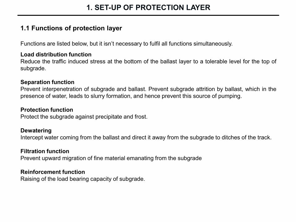
1.1 Functions of protection layer
Functions are listed below, but it isn’t necessary to fulfil all functions simultaneously.
Load distribution function
Reduce the traffic induced stress at the bottom of the ballast layer to a tolerable level for the top of
subgrade.
Separation function
Prevent interpenetration of subgrade and ballast. Prevent subgrade attrition by ballast, which in the
presence of water, leads to slurry formation, and hence prevent this source of pumping.
Protection function
Protect the subgrade against precipitate and frost.
Dewatering
Intercept water coming from the ballast and direct it away from the subgrade to ditches of the track.
Filtration function
Prevent upward migration of fine material emanating from the subgrade
Reinforcement function
Raising of the load bearing capacity of subgrade.
1. SET-UP OF PROTECTION LAYER

Strengthening effect of protection layer
1. SET-UP OF PROTECTION LAYER

1.2.1 Coarse-grained soil protection layers for track with velocity V 120 km/h
To hinder the drenching of subgrade quasi-watertight material has to be used. It is called coarse-
grained mixture 1 = CGM1). This layer is separated from subgrade by geotextile.
CGM1 has relative higher fine-grained soil content. This mixture is very sensitive to excess of the
optimal construction water content.
Requirements against CGM1:
- mixture has to be produced from crushed stone particles and natural round shaped particles:
o mass percent of crushed stone particles min. 30%,
o mass percent of round shaped particles min. 30%,
o It is allowed to produce the mixture from crushed stone particles in 100%, if the requirements
of compactness and load bearing capacity after construction will be fulfiled according to the
previous tests.
- grain-size distribution curve has to be between the border lines,
- inequality factor has to be Cu 15, it ensure a suitably stable behaviour against dynamic
effects,
- particles’ diameter min. 32 mm max. 63 mm,
- water permeability coefficient k 1x10⁻⁶ m/s at Tr = 100% compactness rate, - frost resistance is suitable, if fine particle content d 0,02 mm is not higher than 3 mass
percent at Cu 15 value.
1.2 Protection layers made out of coarse-grained soil
1. SET-UP OF PROTECTION LAYER
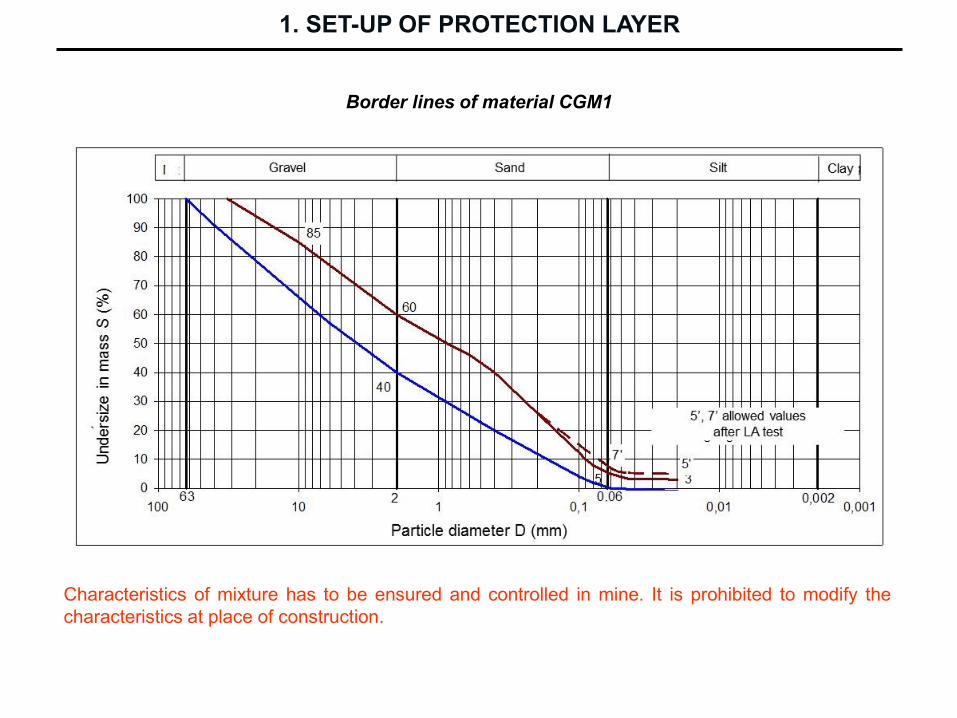
Border lines of material CGM1
1. SET-UP OF PROTECTION LAYER
Characteristics of mixture has to be ensured and controlled in mine. It is prohibited to modify the
characteristics at place of construction.

Finished track section constructed with CGM1 layer
1. SET-UP OF PROTECTION LAYER
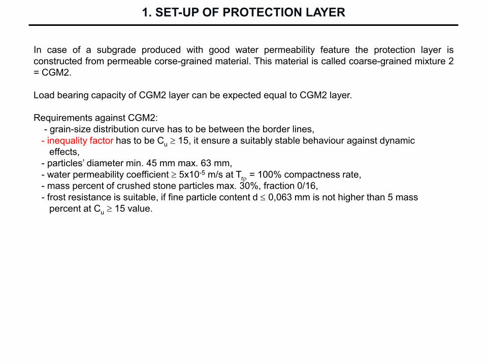
In case of a subgrade produced with good water permeability feature the protection layer is
constructed from permeable corse-grained material. This material is called coarse-grained mixture 2
= CGM2.
Load bearing capacity of CGM2 layer can be expected equal to CGM2 layer.
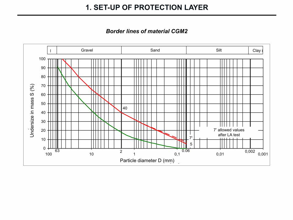
Requirements against CGM2:
- grain-size distribution curve has to be between the border lines,
- inequality factor has to be Cu 15, it ensure a suitably stable behaviour against dynamic
effects,
- particles’ diameter min. 45 mm max. 63 mm,
- water permeability coefficient 5x10⁻⁵ m/s at Tr = 100% compactness rate,
- mass percent of crushed stone particles max. 30%, fraction 0/16,
- frost resistance is suitable, if fine particle content d 0,063 mm is not higher than 5 mass
percent at Cu 15 value.
1. SET-UP OF PROTECTION LAYER
1. SET-UP OF PROTECTION LAYER
Border lines of material CGM2
5
40
7'
0
10
20
30
40
50
60
70
80
90
100
0,0010,010,1110100
Szemcseátmérő D [mm]
Áte
se
tt t
öm
eg
szá
za
lék S
[%
]
Kavics Homok
0,0020,062
AgyagIszap
63
Mk
7' aprózódási próba után
megengedett értékek
Gravel Sand Silt Clay
7’ allowed values
after LA test
Particle diameter D (mm)
Und
ers
ize
in
ma
ss S
(%
)

Use of CGM1 and CGM2 material in tracks with velocity V 120 km/h is possible but not
compulsory.
Characteristics of course-grained material has to be controlled (e.g. grain-size distribution, filtration
function, etc.)
Minimum thickness of protection layer is 20 cm. Due to requirements of frost protection or load
bearing capacity the thickness can be higher than 30 cm.
1. SET-UP OF PROTECTION LAYER
1.2.2 Coarse-grained soil protection layers for track with velocity V ≤ 120 km/h

1. SET-UP OF PROTECTION LAYER
Border lines of course-grained material for tracks with velocity V 120 km/h

Border lines of mixtures in Hungarian practice
Border line Soil
replacement
Protection
layer Fill
Barrier layer
of subgrade Gravel pile
Upper E E C B F
Lower A D B E G
1. SET-UP OF PROTECTION LAYER
In case of secondary tracks on stations the protection layer can be neglected, if
- the load bearing capacity of subgrade is suitably high and equable,
- there is no frost sensitive soil under the surface of subgrade,
- there is no problems between ballast and subgrade in function of filtration and separation,
- there is no water sensitive material in the barrier layer of subgrade,
- it is no necessary to protect the subgrade against the penetrating contaminations.
1.2.3 Needlessness of protection layer
1. SET-UP OF PROTECTION LAYER
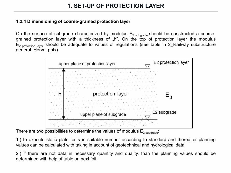
1.2.4 Dimensioning of coarse-grained protection layer
On the surface of subgrade characterized by modulus E2 subgrade should be constructed a course-
grained protection layer with a thickness of „h”. On the top of protection layer the modulus
E2 protection layer should be adequate to values of regulations (see table in 2_Railway substructure
general_Horvat.pptx).
There are two possibilities to determine the values of modulus E2 subgrade:
1.) to execute static plate tests in suitable number according to standard and thereafter planning
values can be calculated with taking in account of geotechnical and hydrological data,
2.) if there are not data in necessary quantity and quality, than the planning values should be
determined with help of table on next foil.
1. SET-UP OF PROTECTION LAYER

Recommended planning values of modulus E2 subgrade
Hydrological case No. 1:
- subgrade surface is well dewatered,
- there are not periodic drenching to a depth of 1,5 m from the rail head level (consistence index Ic
is above 1,00 permanently).
1. SET-UP OF PROTECTION LAYER
1. SET-UP OF PROTECTION LAYER
Hydrological case No. 2:
- dewatering of subgrade surface is inadequate,
- above the depth of 1,5 m from the rail head level periodic drenching can be occurred
(consistence index Ic is between 0,75 and 1,00).
Hydrological case No. 3:
- dewatering of subgrade is not solved, theee is permanent onflow,
- above the depth of 1,5 m from the rail head level permanent drenching is characteristic
(consistence index Ic is lower than 0,75).

Dimensioning diagram for protection layer made out of course-grained material
for increasing of load bearing capacity
1. SET-UP OF PROTECTION LAYER

1.2.5 Set-up of course-grained protection layer
1. SET-UP OF PROTECTION LAYER
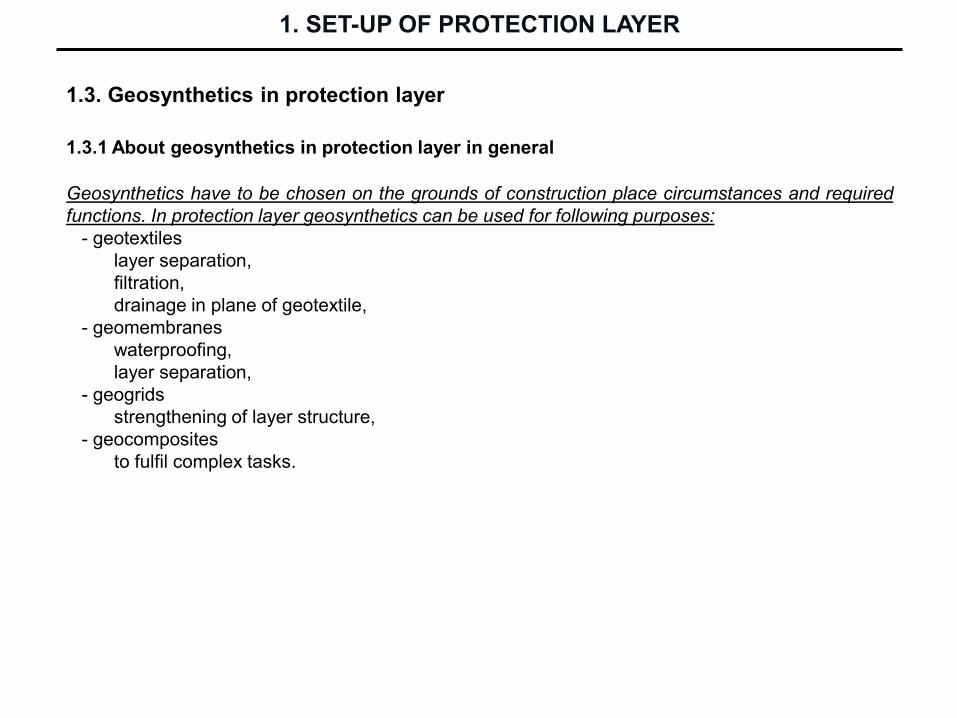
1.3. Geosynthetics in protection layer
Geosynthetics have to be chosen on the grounds of construction place circumstances and required
functions. In protection layer geosynthetics can be used for following purposes:
- geotextiles
layer separation,
filtration,
drainage in plane of geotextile,
- geomembranes
waterproofing,
layer separation,
- geogrids
strengthening of layer structure,
- geocomposites
to fulfil complex tasks.
1.3.1 About geosynthetics in protection layer in general
1. SET-UP OF PROTECTION LAYER
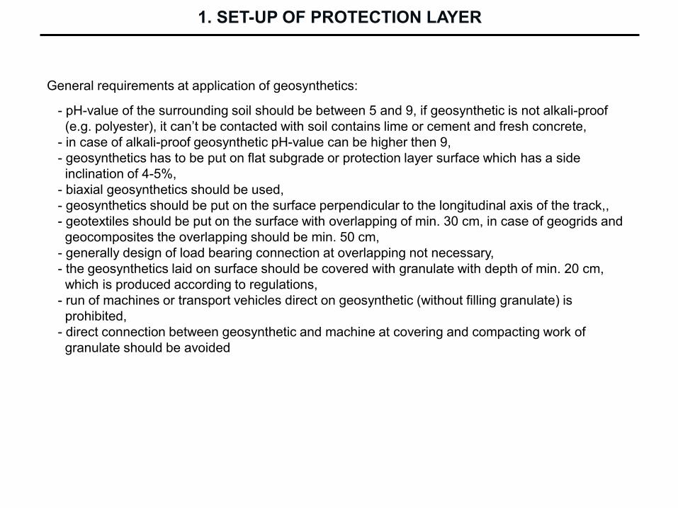
General requirements at application of geosynthetics:
- pH-value of the surrounding soil should be between 5 and 9, if geosynthetic is not alkali-proof
(e.g. polyester), it can’t be contacted with soil contains lime or cement and fresh concrete,
- in case of alkali-proof geosynthetic pH-value can be higher then 9,
- geosynthetics has to be put on flat subgrade or protection layer surface which has a side
inclination of 4-5%,
- biaxial geosynthetics should be used,
- geosynthetics should be put on the surface perpendicular to the longitudinal axis of the track,,
- geotextiles should be put on the surface with overlapping of min. 30 cm, in case of geogrids and
geocomposites the overlapping should be min. 50 cm,
- generally design of load bearing connection at overlapping not necessary,
- the geosynthetics laid on surface should be covered with granulate with depth of min. 20 cm,
which is produced according to regulations,
- run of machines or transport vehicles direct on geosynthetic (without filling granulate) is
prohibited,
- direct connection between geosynthetic and machine at covering and compacting work of
granulate should be avoided
1. SET-UP OF PROTECTION LAYER

1.3.2 Geotextiles
Important parameters from point of view of applicability in railway track:
Physical properties
- mass/unit area,
- nominal thickness.
Mechanical properties
- apparent pore size distribution,
- tensile strength,
- elongation at breaking,
- puncture strength.
Hydraulic properties
- water permeability-
- in-plane transmissivity,
- filtration ability.
Resistance properties
- chemical resistance (e.g. reagents in soil),
- physical resistance (e.g. ultra-violet ray),
- frost resistance (it doesn’t become rigid in cold winter) ,
- other environmental resistance (e.g. microbiological resistance).
1. SET-UP OF PROTECTION LAYER

Expected functions of geotextile
1. SET-UP OF PROTECTION LAYER
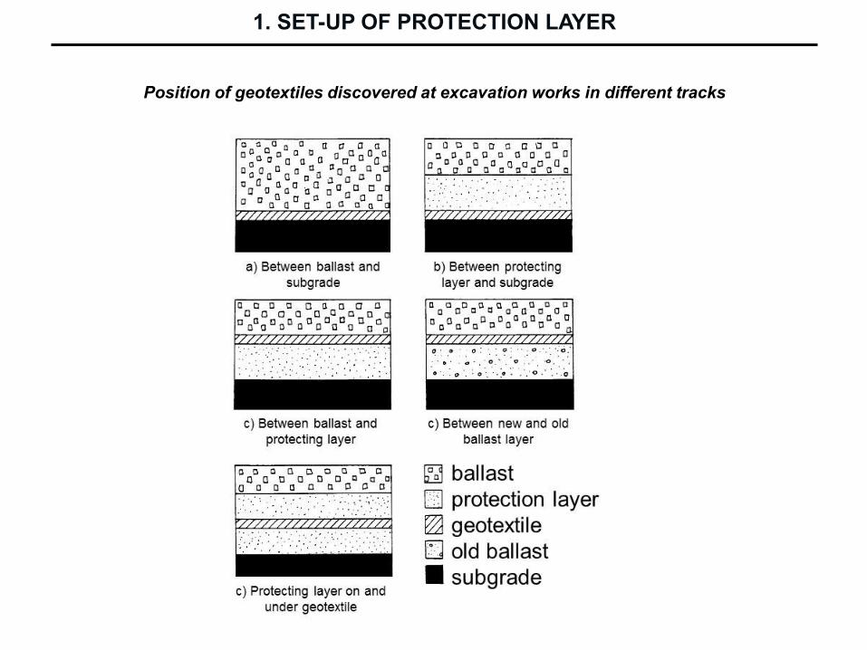
Position of geotextiles discovered at excavation works in different tracks
1. SET-UP OF PROTECTION LAYER

Geotextile types Polyfelt Geotextile types Secutex
Secutex 151-GRK 2
Secutex 141
1. SET-UP OF PROTECTION LAYER

1.3.3. Geogrids
Producing of Tensar type geogrid
1. SET-UP OF PROTECTION LAYER
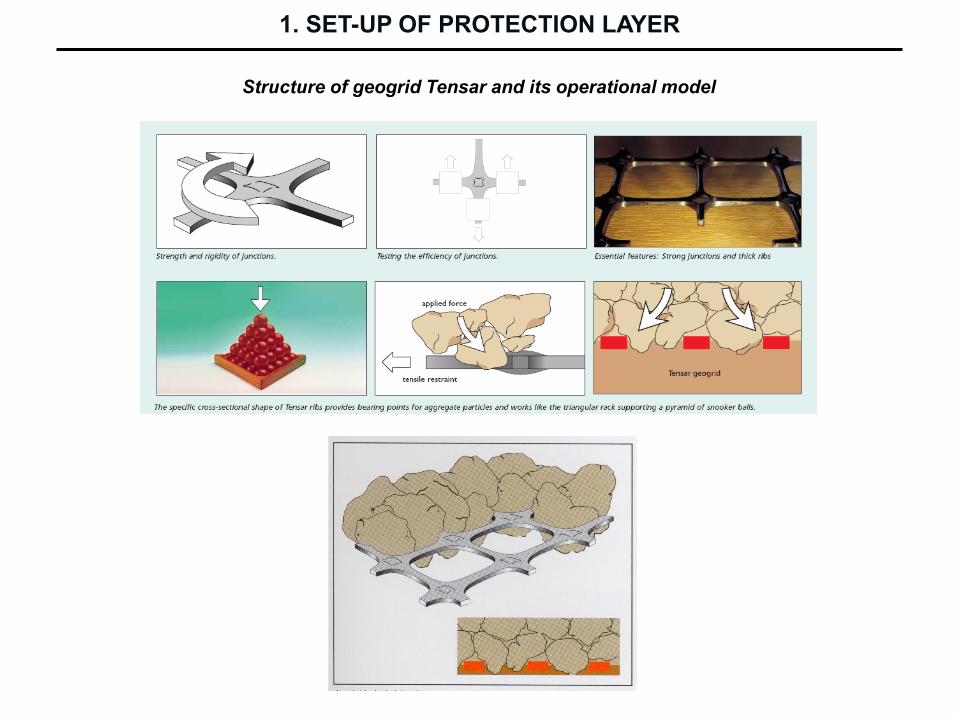
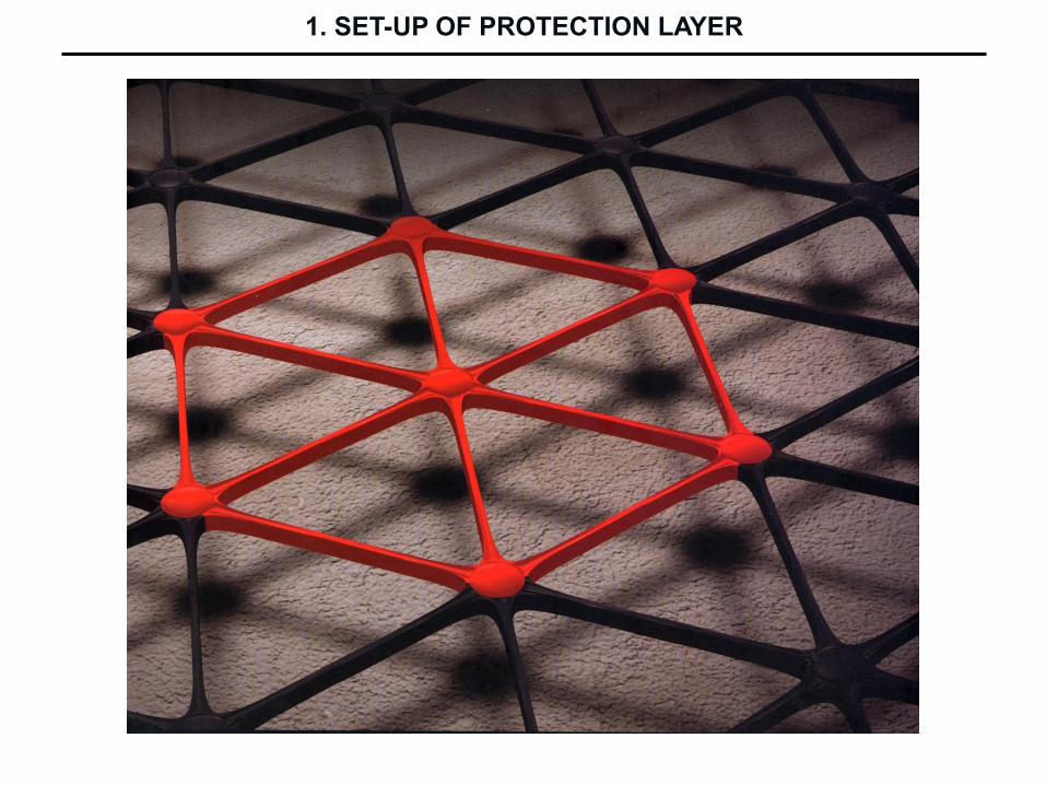
Structure of geogrid Tensar and its operational model
1. SET-UP OF PROTECTION LAYER
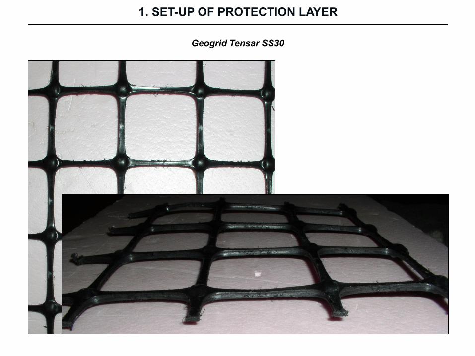
Geogrid Tensar SS30
1. SET-UP OF PROTECTION LAYER
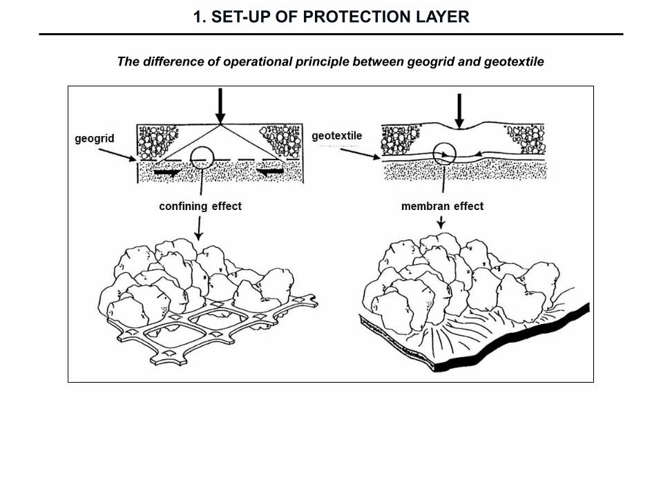
The difference of operational principle between geogrid and geotextile
1. SET-UP OF PROTECTION LAYER
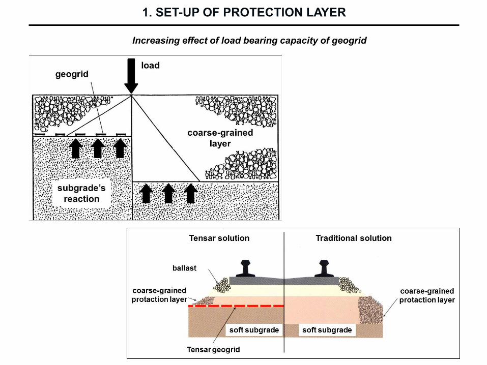
Increasing effect of load bearing capacity of geogrid
1. SET-UP OF PROTECTION LAYER

Layer structures with Tensar geogrid
1. SET-UP OF PROTECTION LAYER
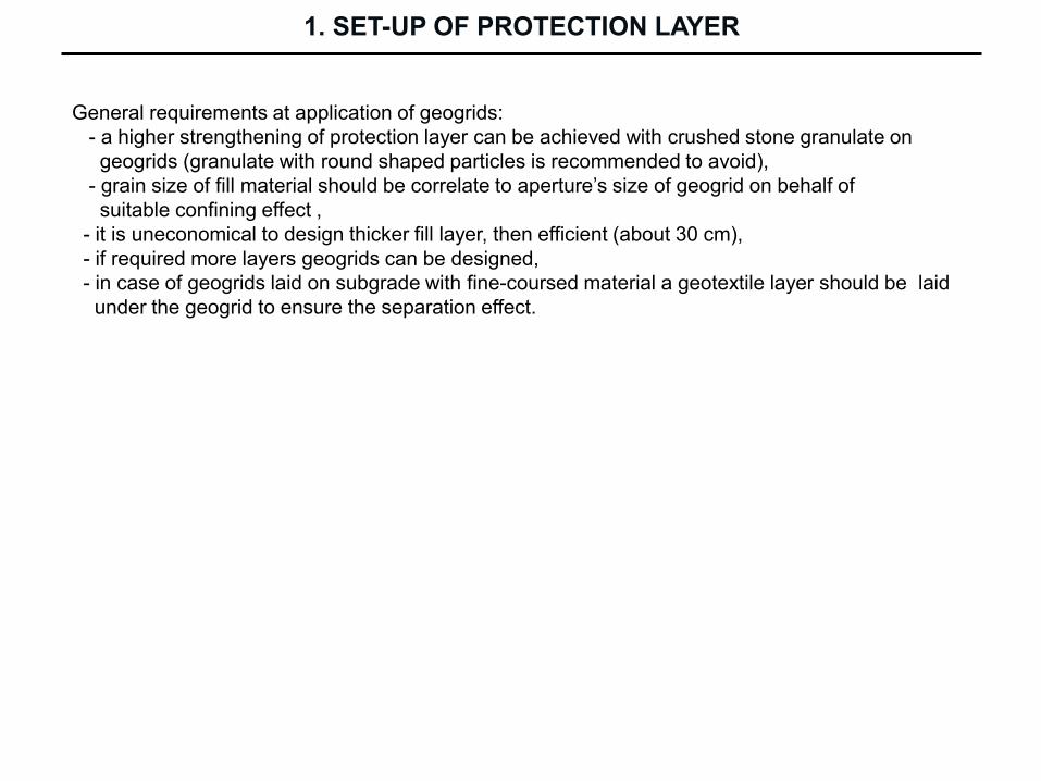
General requirements at application of geogrids:
- a higher strengthening of protection layer can be achieved with crushed stone granulate on
geogrids (granulate with round shaped particles is recommended to avoid),
- grain size of fill material should be correlate to aperture’s size of geogrid on behalf of
suitable confining effect ,
- it is uneconomical to design thicker fill layer, then efficient (about 30 cm),
- if required more layers geogrids can be designed,
- in case of geogrids laid on subgrade with fine-coursed material a geotextile layer should be laid
under the geogrid to ensure the separation effect.
1. SET-UP OF PROTECTION LAYER
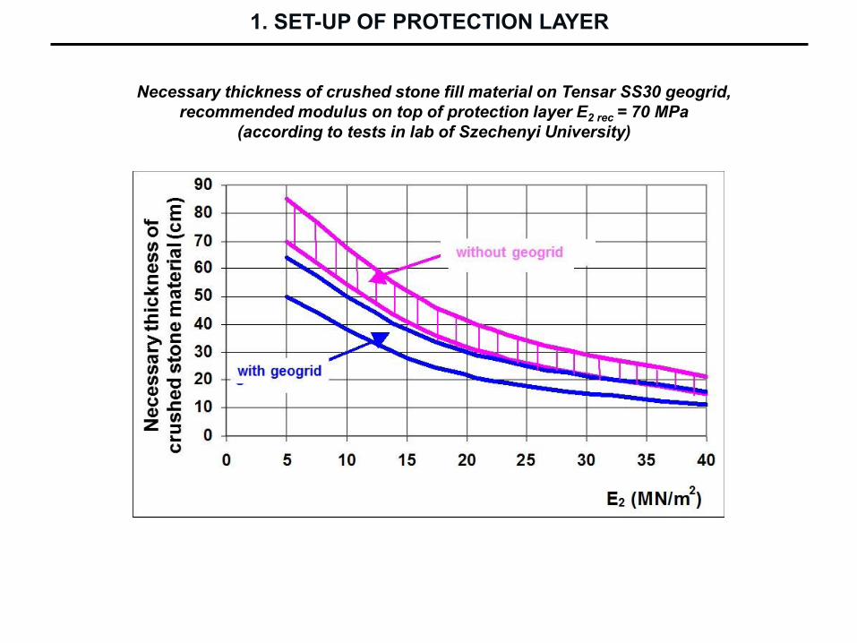
Necessary thickness of crushed stone fill material on Tensar SS30 geogrid,
recommended modulus on top of protection layer E2 rec = 70 MPa
(according to tests in lab of Szechenyi University)
1. SET-UP OF PROTECTION LAYER

Necessary thickness of crushed stone fill material on Tensar SS30 geogrid,
in function to load bearing capacity on subgrade and requested value on the
top of filling material
1. SET-UP OF PROTECTION LAYER

Dimensioning diagram calculated by TENSARPave computer program
5.16. ábra
QS 0QS 1
QS 2QS 3
UIC osztályozás
E ( EV 2)
(MN/m2)10 20 30 40 50 100
2 4 6 8 10 15 20 30 40 CBR (%)
SNCF
TGV vonalak
D117
Zúzottkő ágyazatmin. vastagsága 30 cm
Zúzottkő ágyazatmin. vastagsága 25 cm
Javítórétegmin. vastagsága 25 cm
SBB
1 csop. vonalakfővágányai
DB
fővonalak
átmenőfővágányai
100
e, cm
50
0
1. SET-UP OF PROTECTION LAYER

German dimensioning diagram
Material source: Göbel – Lieberenz: Handbuch Erdbauwerke der Bahnen
1. SET-UP OF PROTECTION LAYER

German type structures (calculated on load bearing capacity and frost)
Material source: Göbel – Lieberenz: Handbuch Erdbauwerke der Bahnen
1. SET-UP OF PROTECTION LAYER

Geogrid type Tensar TriAx™
This type of geogrid was introduced in the year 2008.
Pulling rigidity of biaxial geogrids in diagonal direction is much lower then in direction of
ribs. Geogrid type Tensar TriAx™ can hinder the particles’ movement in all directions of
the reinforcing plane with approximately equivalent rigidity.
1. SET-UP OF PROTECTION LAYER
1. SET-UP OF PROTECTION LAYER

Rigidity of Tensar geogrids
1. SET-UP OF PROTECTION LAYER
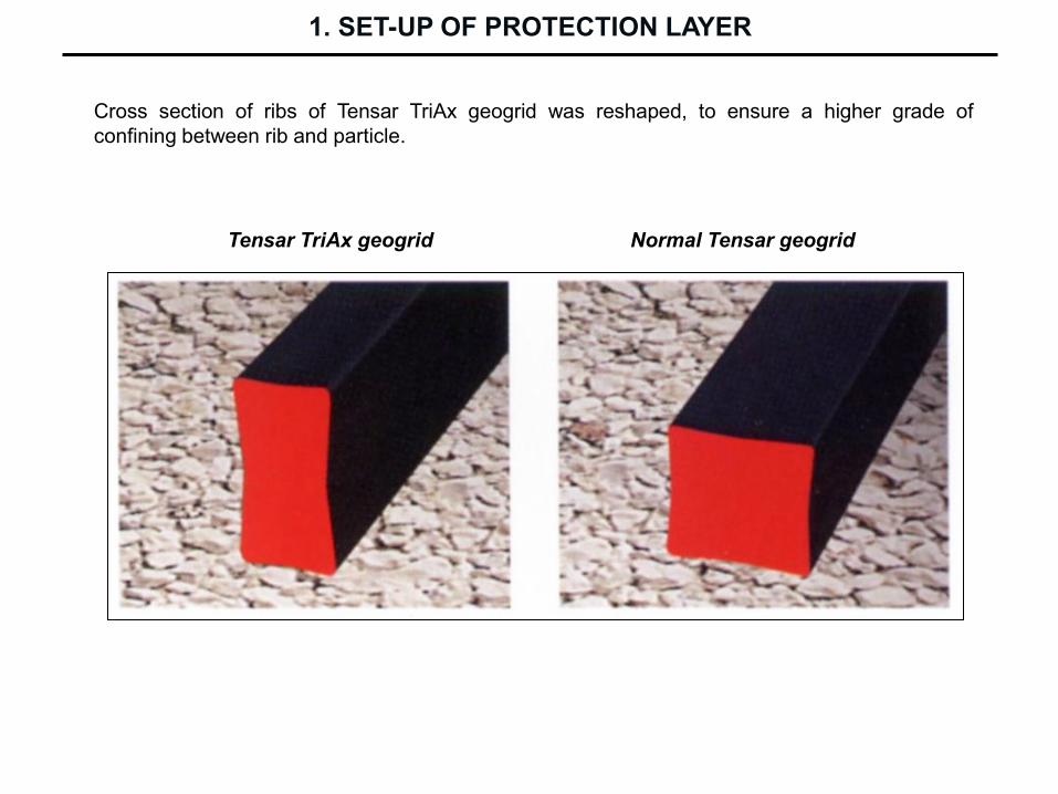
Cross section of ribs of Tensar TriAx geogrid was reshaped, to ensure a higher grade of
confining between rib and particle.
Tensar TriAx geogrid Normal Tensar geogrid
1. SET-UP OF PROTECTION LAYER

Layer structure in cut on railway line Zalalövő – Bajánsenye
1. SET-UP OF PROTECTION LAYER

Load bearing capacity of layer structure built with Tensar SS geogrids
Initial values on subgrade surface before rehabilitation works was under 10 MPa.
Layer structure type No. 1 on line Zalalövő - Bajánsenye
sectioning 404+00 - 415+00
1. SET-UP OF PROTECTION LAYER

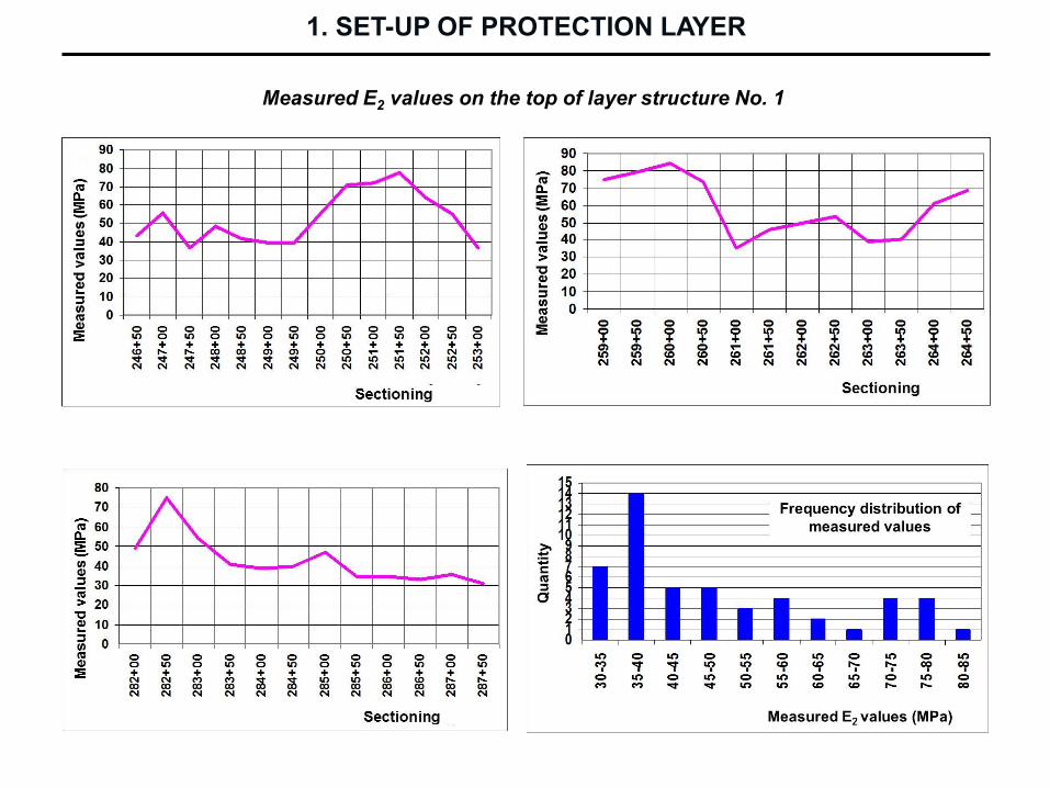
Measured E2 values on the top of layer structure No. 1
1. SET-UP OF PROTECTION LAYER
1. SET-UP OF PROTECTION LAYER
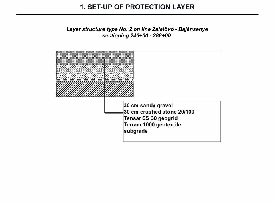
Layer structure type No. 2 on line Zalalövő - Bajánsenye
sectioning 246+00 - 288+00
1. SET-UP OF PROTECTION LAYER
Measured E2 values on the top of layer structure No. 1

Reinforcing effect of layer structure No.2 according to the values of control
measurements
1. SET-UP OF PROTECTION LAYER

1. SET-UP OF PROTECTION LAYER
Layer structure type No. 2 on line Zalalövő - Bajánsenye
sectioning 30+00 - 91+00

Geogrid types Secugrid
1. SET-UP OF PROTECTION LAYER
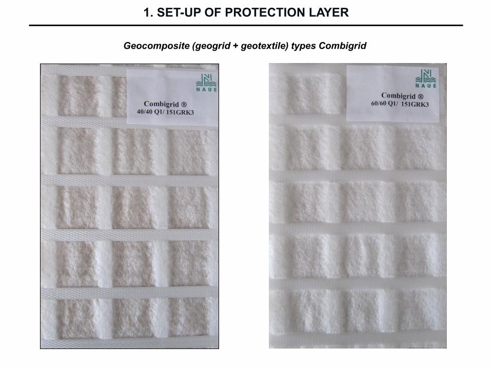
Geocomposite (geogrid + geotextile) types Combigrid
1. SET-UP OF PROTECTION LAYER
Asphalt protection layer can be constructed, if
- the subgrade with weak load bearing capacity should be reinforced and
- a watertight covering layer should be laid on the subgrade..
With asphalt protection layer the further positive effects can be reached as well:
- distribution and damping of static and dynamic actions generated by railway vehicles,
- reduction of deformation on surface of subgrade,
- layer separation (ballast and sublayer),
- reduction of frost danger,
- reduction of vibration,
- resistance against capillarity,
- stabile subgrade surface,
- reduction of track maintenance costs.
General requirements at application of asphalt protection layer:
- minimum thickness 12 cm,
- coarse-grained layer should be constructed between subgrade and asphalt layer (thickness
should be calculated),
- asphalt layer should be constructed on the whole surface of subgrade unto the edge of track
benches,
- slopes should be protected against meteoric water coming from asphalt layer intensively.
1.4 Asphalt protection layer
1. SET-UP OF PROTECTION LAYER

Cross section on high speed railway line A Rome – Florence
Hungarian example
1. SET-UP OF PROTECTION LAYER
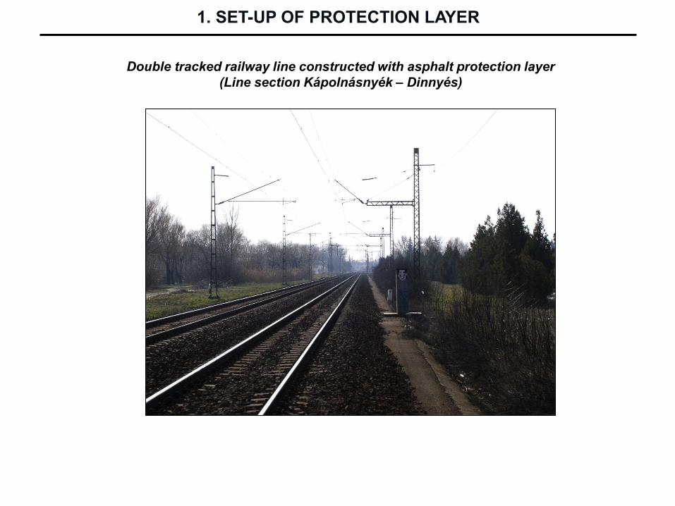
Double tracked railway line constructed with asphalt protection layer
(Line section Kápolnásnyék – Dinnyés)
1. SET-UP OF PROTECTION LAYER
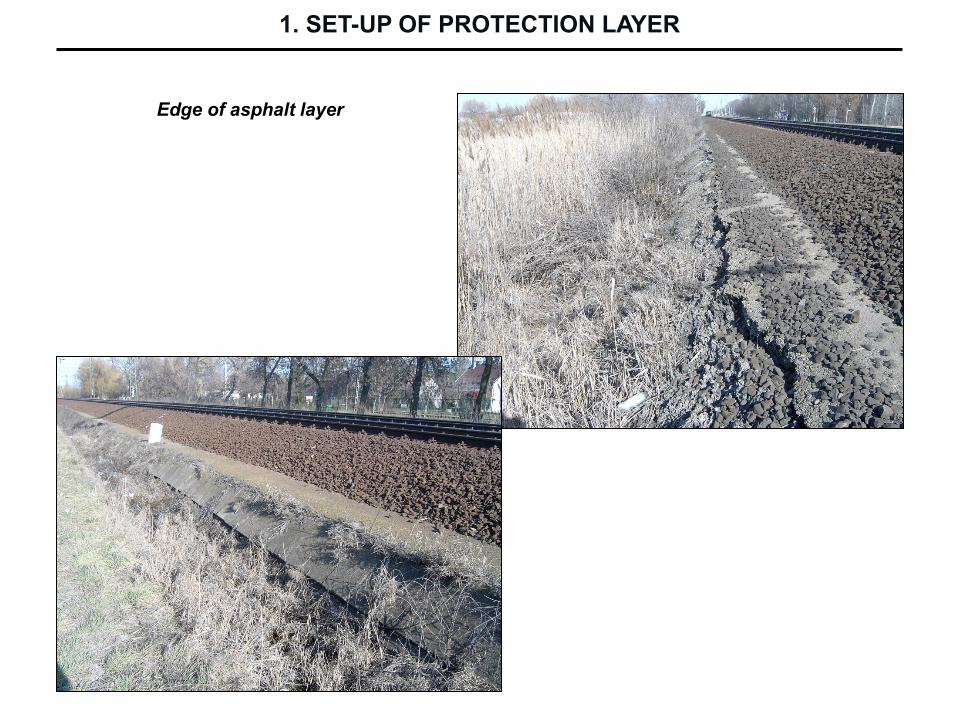
Edge of asphalt layer
1. SET-UP OF PROTECTION LAYER

Breakage of crushed stone ballast and flowing mud
1. SET-UP OF PROTECTION LAYER