roads and watercourse crossings guidelinesguidelines for roads and watercourse crossings chapter 1...
TRANSCRIPT

April 20, 2004
DISPONIBLE EN FRANÇAIS
Guidelines for
ROADS AND WATERCOURSE CROSSINGS

Inquiries regarding this document should be directed to: Forest Management Branch Natural Resources Hugh John Flemming Forestry Centre 1350 Regent Street, Room 340 Fredericton, New Brunswick Canada E3C 2G6 Tel: (506) 453-2516 Fax: (506) 453-6689
Guidelines for Roads and Watercourse Crossings Table of Contents
i
Table of Contents
List of Figures................................................................................................................................ ii
List of Tables ................................................................................................................................ iii
1 Forest Road Planning and Construction .............................................................................. 1 1.1 INTRODUCTION ....................................................................................................................................................1 1.2 PLANNING............................................................................................................................................................1
1.2.1 Design Requirements and Specifications.....................................................................................................3 1.2.2 Work Instructions.........................................................................................................................................4
1.3 RIGHT-OF-WAY (ROW) LOCATION AND CLEARING............................................................................................5 1.3.1 On-the Ground Layout.................................................................................................................................5 1.3.2 Flagging.......................................................................................................................................................5
1.4 STEPS IN ROAD CONSTRUCTION ..........................................................................................................................5 1.4.1 Clearing, Grubbing and Stripping...............................................................................................................6 1.4.2 Subgrade Construction ................................................................................................................................7 1.4.3 Compaction..................................................................................................................................................9
1.5 CONTROL OF SURFACE WATER............................................................................................................................9 1.5.1 Ditches .........................................................................................................................................................9 1.5.2 Off-Take Ditches and Cross-Drainage Culverts........................................................................................11 1.5.3 Settling Ponds ............................................................................................................................................13 1.5.4 Water Bars .................................................................................................................................................13 1.5.5 Ditch Blocks...............................................................................................................................................14
1.6 WATERCOURSE CROSSINGS ...............................................................................................................................15 1.7 ROAD MAINTENANCE ........................................................................................................................................15
1.7.1 Clearing Width Maintenance.....................................................................................................................15 1.7.2 Maintenance of the Road Surface ..............................................................................................................16 1.7.3 Ditch Maintenance.....................................................................................................................................17 1.7.4 Maintenance of Stream Crossings .............................................................................................................17 1.7.5 Signs ..........................................................................................................................................................18
2 Watercourse Crossings......................................................................................................... 19 2.1 INTRODUCTION ..................................................................................................................................................19 2.2 PLANNING..........................................................................................................................................................19 2.3 CHANNEL WIDTH ..............................................................................................................................................20 2.4 ENVIRONMENTAL CONSIDERATIONS .................................................................................................................22
2.4.1 Erosion and Sediment Control...................................................................................................................22 2.5 “IN-THE-DRY” ...................................................................................................................................................22
2.5.1 Exemptions to “In-the-dry” Installations ..................................................................................................22 2.5.2 Planning and Preparedness for Watercourse Crossings ...........................................................................23 2.5.3 Isolating the Work Site...............................................................................................................................24
2.6 DETERMINATION OF STRUCTURE TYPE..............................................................................................................27 2.7 DETERMINATION OF “FISH-BEARING” STREAMS................................................................................................28
2.7.1 Design Options for Fish Passage ..............................................................................................................28 2.8 DETERMINATION OF REQUIRED OPENING SIZE ..................................................................................................30
2.8.1 Bridges.......................................................................................................................................................31 2.8.2 Bottomless Culverts ...................................................................................................................................34 2.8.3 Pipe Culverts .............................................................................................................................................36 2.8.4 Preparation and Installation of Culverts ...................................................................................................37 2.8.5 Fording ......................................................................................................................................................43

Guidelines for Roads and Watercourse Crossings Table of Contents
ii
2.8.6 Temporary Crossings.................................................................................................................................45
3 Erosion and Sedimentation Control Measures .................................................................. 52 3.1 INTRODUCTION ..................................................................................................................................................52 3.2 GROUND VEGETATION NEAR WATERCOURSES..................................................................................................52 3.3 SLASH AND DEBRIS ...........................................................................................................................................52 3.4 EROSION AND SEDIMENT CONTROL MEASURES ................................................................................................53
3.4.1 Isolating the Work Site...............................................................................................................................53 3.4.2 Sediment Traps and Silt Barriers...............................................................................................................53 3.4.3 Silt Fences..................................................................................................................................................54 3.4.4 Straw Bales ................................................................................................................................................56 3.4.5 Vegetation Soil Stabilization......................................................................................................................57 3.4.6 Erosion Control Blankets and Netting.......................................................................................................58 3.4.7 Riprap ........................................................................................................................................................59
3.5 DRAINAGE CONTROL.........................................................................................................................................59 3.6 HANDLING HAZARDOUS SUBSTANCES ..............................................................................................................59
Glossary ....................................................................................................................................... 61
APPENDIX A.............................................................................................................................. 69
APPENDIX B .............................................................................................................................. 74
APPENDIX C.............................................................................................................................. 77
APPENDIX D.............................................................................................................................. 79
List of Figures
Figure 1. Preparation and planning prior to implementation is an important step that must not be overlooked...........2 Figure 2. Typical road cross-section (Adapted from: FERIC, 1999)............................................................................4 Figure 3. Bridge crossing construction .......................................................................................................................11 Figure 4. Installation of a cross-drainage and slope from inlet to outlet.....................................................................12 Figure 5. Specifications for water bar construction ....................................................................................................14 Figure 6. Representation of streambed and streambank position. ..............................................................................21 Figure 7. Representative sample of proper channel measurement technique .............................................................21 Figure 8. Pump around system ...................................................................................................................................24 Figure 9. Guidelines for construction of intake screens for pump-around operations associated with in-the- dry
watercourse crossings. .........................................................................................................................................25 Figure 10. Cofferdams are temporary water barriers that can be used alone, when isolating shoreline areas or in
conjunction with temporary diversions................................................................................................................26 Figure 11. Temporary stream diversion channel is best suited for alterations where site space is not limited...........27 Figure 12. Using a map with contour intervals, the drainage area of any point in a watercourse can be found by
connecting the highest points of land, surrounding the watercourse and tributaries, upstream of that point. This area is then converted into flow (cfs) and opening size can be determined from a nomograph or table (Appendix D).........................................................................................................................................................................30
Figure 13. Determination of appropriate watercourse crossing structures..................................................................31 Figure 14. Parameters for calculating waterway opening of a bridge.........................................................................34 Figure 15. Types of culvert installations ....................................................................................................................36 Figure 16. Identification of standards required for culvert installation.......................................................................37

Guidelines for Roads and Watercourse Crossings Table of Contents
iii
Figure 17. Proper alignment of culvert installations...................................................................................................38 Figure 18. Proper installation of culverts for fish passage..........................................................................................38 Figure 19. Proper installation of culverts to provide adequate fish passage. ..............................................................39 Figure 20. Multiple culverts are often used to pass high water flows in areas susceptible to flooding. A maximum of
two culverts may be installed at any given alteration site....................................................................................40 Figure 21. Culvert crossing construction. ...................................................................................................................43 Figure 22. Stream cross-section of a ford identifying the need for a sufficient dip to ensure water cannot breach the
ford and run down the approaches as well as appropriate use of the non-erodible material................................45 Figure 23. Temporary bridge with single sill log .......................................................................................................48 Figure 24. Layout of a sediment trap. .........................................................................................................................54 Figure 25. Silt fence installation showing wire support for filter fabric and backfilled trench. .................................54 Figure 26. Straw bale installation showing staking and placement to retain sediment. ..............................................57 Figure 27. Procedure for using fibre mats to speed revegetation adjacent to road approach slopes. ..........................59
List of Tables
Table 1. Recommended ice thickness for various activities during winter operations. ..............................................50 Table 2. Corrugated steel circular / pipe culvert and corresponding drainage area for watercourses depicted on the
1:10,000 orthophoto map.....................................................................................................................................79 Table 3. Concrete or plastic circular / pipe culvert and corresponding drainage areas for watercourses depicted on
the 1:10,000 orthophoto map. ..............................................................................................................................80 Table 4. Corrugated steel pipe arch culvert and corresponding drainage area. for watercourses depicted on the
1:10,000 orthophoto map.....................................................................................................................................81


Guidelines for Roads and Watercourse Crossings Chapter 1 Forest Road Planning and Construction
1
1 Forest Road Planning and Construction
1.1 Introduction This section is aimed at assisting both operators and managers in meeting road construction and maintenance objectives. The Forest Management Plan's 25-year blocking strategy should be used to determine road use requirements including vehicle size, loading and volume of traffic. Roads should then be designed to meet those requirements. Successful forest road construction involves: 1. Knowing the standard of road to be constructed (Forest, Logging, Winter or Temporary),
2. Understanding all pertinent Acts and Regulations surrounding construction,
3. Designing and constructing roads that meet the requirements of the objectives and that recognize hazards, sensitive terrain and forest resource values,
4. Designing measures to minimize potential environmental impacts,
5. Following design specifications during construction and modifying them if unexpected field conditions are encountered (with prior approval by DNR)
6. Monitoring the construction to ensure the objectives are being met.
1.2 Planning In planning for roads (Figure 1), the following guidelines should be followed in order to optimize the layout as well as account for known conditions and/or special management considerations:
1. Utilize all available information to indicate significant features on the landscape:
a) Special Management Areas (DWA, OFSH, Protected Natural Areas, PSP, Unique Areas, Designated Watersheds, etc.)
b) Watercourses
2. Review available soil information to establish suitable road locations and help highlight potentially wet, erodible or unstable areas.
3. Minimize the number of stream crossings, and show preference towards rocky or hard bottom sites. Make use of unmapped stream location information and/or assess contours to estimate potential intermittent streams.

Guidelines for Roads and Watercourse Crossings Chapter 1 Forest Road Planning and Construction
2
4. Amendments to road construction plans should be considered using the most up-to-date information available.
5. Always locate roads outside designated riparian buffers when roads are running parallel to stream channels. Ensure that an adequate filter strip is provided, in consideration of soils and topography, to prevent sediment from directly entering the stream in accordance with all applicable regulations.
6. Wherever practical, make use of existing roads and/or old trail systems, including adjacent landowners' road systems.
7. Fit the road to the topography by locating roads on natural benches and following contours. Where practical, avoid long, steep road grades and narrow gullies.
8. Make all necessary adjustments to the layout to ensure safety including road widening at bridge crossings and crests of hills, appropriate curve specifications, etc.
9. Plan appropriate placement of turnouts and widenings
Figure 1. Preparation and planning prior to implementation is an important step that must not be overlooked

Guidelines for Roads and Watercourse Crossings Chapter 1 Forest Road Planning and Construction
3
1.2.1 Design Requirements and Specifications Design requirements are essentially the engineering and structural requirements of a road necessary to meet its intended use, longevity and season of operation. They cover everything from dimensions, type of materials, sighting distances, fill slopes and drainage specifications. In addition to the legal standards, the minimum road design requirements that should be met in any road construction project include alignment, road construction features and other operational criteria. 1.2.1.1 Road class The four major types of roads on Crown lands are: Forest Road: The permanent main road system of a License designed to provide access for forest management activity, mineral resource development and recreational use. The Licensee lists all forest roads on the License in their Forest Management Plan. Logging Road: All permanent roads on a License not designated as forest roads. They include roads leading directly to and within harvest blocks. Winter Road: Seasonal road, only used after ground is frozen. Limited only to areas where logging roads cannot be constructed. Temporary Roads: Limited to 400 m in length to access wood where no further road development beyond this point is planned. Within one year after harvest completion, the area of the road must be reclaimed and reforested at the expense of the operator. 1.2.1.2 Road alignment Road design should incorporate horizontal and vertical road alignments that provide user safety. This involves establishing: 1. appropriate travel speeds,
2. suitable stopping and sight distances,
3. single- or double-lane road widths,
4. turnouts,
5. appropriate traffic control devices,
6. sight distance, and
7. traffic volume.

Guidelines for Roads and Watercourse Crossings Chapter 1 Forest Road Planning and Construction
4
1.2.1.3 Road construction features Road construction features are what determine the overall class of a road, which includes its period of use, load capacity and life span. The standard road requires a basic set of design specifications to indicate the right-of-way (ROW), suitable materials for each part of the road, depth and/or height requirements on all structures, etc (see Forest Management Manual for legal requirements). Fill slope angles: Fill slope angles should be designed such that the soil or rock materials are stable. Wherever possible, a 2:1 horizontal to vertical slope should be used. Where rip rap or other less erodible materials are used, a 1.5:1 slope may be used. In cases of extremely erodible surfaces, a 3:1 slope may be warranted (Figure 2). Cut slope angles: Cut slope angles should be designed to remain stable over the expected life of the road. A 2:1 slope should be achieved where possible. If this is not possible due to site conditions, stabilization measures must be used. Clearing widths: Clearing widths should be minimized wherever possible to reduce impacts on other resources but wide enough to accommodate the road and its associated surface drainage features. Road alignment features such as line of sight and planned widening and turnouts.
Right of Way
Sub-base
Road-base
Road-surfaceShoulderShoulder
1.5:1slope
1.5:1slope
1.5:1slope
Forest
Forest
Crown Height
Ditch
Figure 2. Typical road cross-section (Adapted from: FERIC, 1999) 1.2.1.4 Operational criteria All classes of road must meet traffic needs for passing and turning. The construction of turnouts and meeting places should be built as required and must not interfere with the surface water drainage system. 1.2.2 Work Instructions A work order or contractual agreement between the Licensee and road construction contractor is encouraged. Work instructions for roads are typically incorporated into contracts made with road construction contractors. In order to ensure that plans and layout are understood by the machine operators, the contractor should walk the proposed road with maps and other

Guidelines for Roads and Watercourse Crossings Chapter 1 Forest Road Planning and Construction
5
information in hand before operations begin. This will familiarize the contractor with the layout and design and the ground conditions, which will provide an opportunity to identify potential problems early on and develop alternative approaches prior to commencement of operations. Regardless of prior planning, the on-site supervisor always has the opportunity to suggest modifications to the plan. While most minor modifications can be made at the discretion of the supervisor (e.g. hauling fill from a borrow pit), major changes (e.g. major detour from proposed route, widening of ROW through buffers, etc.) require approval of DNR.
1.3 Right-of-Way (ROW) Location and Clearing 1.3.1 On-the Ground Layout Layout of forest roads involves the conscious effort to provide the best possible access at the lowest possible cost; both financially and environmentally. On-the-ground layout is critical for ensuring the proper implementation of the road layout plan. This step represents the final safeguard in the event of unforeseen hazards, concerns or other potential modifications (e.g. unmapped streams, raptor nests, etc.) 1.3.2 Flagging Proper flagging of the planned road is essential to its successful implementation on the ground.
1. Flag roadway centre-lines and/or ROW (side lines)
2. Use designated colour flagging tape to indicate regular ROW and environmental concerns (e.g. stream crossings, buffers, etc.).
3. On approach to stream crossings, flag ROW and centre-line to indicate narrowing of ROW width through the designated buffer.
1.4 Steps in Road Construction The construction of a new road consists of up to six steps depending on the class of road. These steps include: 1. clearing of the ROW, 2. grubbing and stripping, 3. building of the subsurface or foundation, 4. surfacing, 5. grading, 6. the development of all necessary surface drainage features

Guidelines for Roads and Watercourse Crossings Chapter 1 Forest Road Planning and Construction
6
1.4.1 Clearing, Grubbing and Stripping Clearing involves the removal of standing trees within the ROW as well as any trees outside the clearing width which threaten the safety of road workers or users (“danger trees”). The following points are guidelines for this phase of road construction:
1. Use flagging to guide clearing activities
2. On Crown land, no harvest of non-merchantable wood is allowed in rights-of-way within 10 m of any watercourse, regardless of its width.
3. At no time are trees to be felled into water bodies.
Following the clearing of the ROW, the area consisting of the road surface, shoulders and ditches including their banks should normally be grubbed and stripped. Grubbing includes the removal of stumps, roots and downed or buried logs. Stripping includes the removal of other organic material and mineral soil unsuitable for forming the road subgrade.
� For natural watercourses whose channel is 0.5 m or wider, a 30 m no-grub zone shall be maintained except immediately underlying the roadbed.
� For natural watercourses whose channel is less than 0.5 m, a 10 m no-grub zone shall be
maintained except immediately underlying the roadbed. 1.4.1.1 Disposal of slash and debris Options for disposal of the slash and debris from grubbing and stripping include burying, trenching, scattering, bullpenning and end-hauling.
1. Buried material should be compacted, covered with a minimum of 30 cm of soil and conform to the general ground profile. Material should not be buried within 30 m of a watercourse or be placed such that it interferes with roadway or other drainage, planned road improvements, snow removal, design sight distance, future developments or standing timber
2. Trenching is the preferred method of disposal for roads built using excavators since trenches alongside the road are made to find suitable subgrade and/or surfacing material. The slash and debris is then placed and packed into the trench and covered over with soil.
3. Piling slash and debris into "bullpens" or windrows is used primarily for roads constructed using a bulldozer. Natural openings and landings should be used where possible and slash and debris must not be piled into standing timber. Bullpens should not be located within 30 m of a watercourse. For fire and aesthetic reasons, bullpens must be flattened and covered with soil.
4. Scattering of excess slash and debris and unsuitable soils should always be placed downslope of the road shoulder and away from standing timber. Scattering should only be considered where fire and pest hazards are low and aesthetic concerns are not an issue.

Guidelines for Roads and Watercourse Crossings Chapter 1 Forest Road Planning and Construction
7
The material must be spread and accumulations breached to accommodate drainage, snow removal and wildlife passage.
5. Where slash, debris, and unsuitable or unusable material cannot be placed locally, end-hauling to a suitable waste site is required. Once end-hauled, the slash and debris should be treated with one of the above noted options. The following points should be considered when end-hauling is required:
Where possible and practical, organic and fine textured soils should be stockpiled for placement over abandoned borrow and waste sites to facilitate revegetation. 1.4.2 Subgrade Construction 1.4.2.1 Borrow pit locations As a general rule, any pits and quarries required must be excavated well away from riparian buffers. They must be located outside the no-grub zone from the nearest stream to allow construction of silt traps capable of trapping fines originating from the pit. The base of the pit should be sloped away from the stream and drainage structures built to prevent water from entering the stream directly from the pit. Natural surface drainage patterns must be maintained. 1.4.2.2 Stabilizing subgrade Stabilization of the subgrade is necessary to ensure that the road is able to meet its load design requirements. Where the sub-grade will not be able to support the design load during its intended period of use, the area should be backfilled with material having the following characteristics:
1. good drainage
2. gravel-like angular rocks with good packing properties
3. erosion resistant.
With excavator construction, this material is pulled onto the subgrade and surface from trenches or pockets along side the road. In some situations, geotextiles or synthetic mats should be considered if desired materials are not available. A number of factors should be considered in the selection of ballast materials, including:
1. design loads
2. expected road life
3. material availability and cost
4. properties of the in situ material under the roadway
5. operational and environmental conditions (erosion hazard and consequence).

Guidelines for Roads and Watercourse Crossings Chapter 1 Forest Road Planning and Construction
8
1.4.2.3 Surfacing Surfacing with gravel is usually required for one or more reasons:
1. The subgrade is too rough (usually rock) to form a drivable or gradeable surface
2. Fine-grained subgrade material needs to be prevented from eroding due to water or wind action.
Surfacing materials The ideal surfacing materials include crushed aggregate and sorted well-graded gravels. These materials are capable of withstanding the deleterious effects of exposure to water, freeze-thaw, handling, spreading and compacting. Aggregate particles should be uniform in quality and free from an excess of flat or elongated pieces. Crushed aggregate is expensive to produce, and should be protected with a base coarse stabilizer (for example, calcium chloride or magnesium chloride, installed to the manufacturers’ specifications), to prevent the loss of fines. In general, content of fines by volume should be in the 7-12 % range. Materials with too high a percentage of fines have less strength, and tend to erode, rut and create excessive dust. Materials that have insufficient fines tend to degrade quickly, and create a rough road surface and are difficult to grade. Aggregate should be angular, not rounded, for optimum strength since rounded rocks compact poorly and have inadequate load bearing properties. A maximum coarse gravel size of 65 mm should be attained where possible. Surfacing procedures 1) Before laying down the gravel, ensure that the road has been properly prepared:
a) culverts and other road drainage structures must be in place and in good repair b) ditches should be properly installed and have no low spots in which water can pool c) the subgrade surface should be smooth, crowned or super-elevated and packed. d) all soft spots in the road subgrade must be repaired in advance of surfacing.
2) Place the minimum depth of gravel or crushed rock needed to attain the objective. Gravel should be placed when both the gravel and the road base are at or near the optimum moisture content (15-20%).
a) Material that is either too wet or too dry when placed is susceptible to rutting later, due to inadequate compaction. If the material is too dry, or if it is deficient in fines, adding water combined with compaction will ensure satisfactory gravel strength.
3) Consider shutting down gravelling operations when:
a) the gravel is frozen
b) excessive rutting occurs (e.g. during wet weather)

Guidelines for Roads and Watercourse Crossings Chapter 1 Forest Road Planning and Construction
9
c) unacceptable siltation occurs due to the gravelling operation.
4) Where compacted depth is to be 15 cm or more, place the material in at least two phases, each well graded, shaped and compacted. Where sorting is a possibility, place coarser gravel on the bottom layer and finer gravel on the upper layer.
5) To prevent the loss of fines and binder material and thus a loss of strength, calcium chloride, magnesium chloride or some other approved palliative could be used if approved.
6) Compact and grade the finished surface (including the shoulders) to retain the road shape, including the crown and super-elevation.
7) At no time is a berm to be left on the shoulders of a road.
1.4.3 Compaction Whether or not surfacing material is to be applied, stabilizing material should be compacted thoroughly to minimize settling, erosion, punching-out, ponding and future maintenance costs. In some cases, such compaction may require the use of specialized compaction equipment.
1.5 Control of Surface Water The road surface is an important water control element. Measures to mitigate surface erosion include insloping, outsloping, crowning, surfacing and creating grade breaks. These measures should be incorporated into road design and construction to minimize surface water velocity and the potential for concentrated flows in the ditch line. Minimization of the impacts of soil erosion on the cut and fill banks and within the ditch line should also be considered. Drainage control is critical to the successful retention of sediments both during and after construction and needs to be considered in relationship to the existing drainage pattern on the site. The two most effective steps in reducing water-related problems are (1) reducing the volume of approach ditchwater and (2) preventing ditchwater from draining into the stream. Throughout the construction phase, ditches, cross-drains and temporary or permanent structures must be constructed as water is encountered. Water should not be allowed to accumulate or flow where damage to the environment or subgrade will result, with due consideration for potential storm flows. Temporary drainage structures must be capable of controlling high water likely to be encountered during construction. 1.5.1 Ditches 1.5.1.1 Ditch configuration The configuration of a ditch including its plan profile and cross-sectional design is critical to ensuring that water flow can be managed properly. The gradient and path (direction) of the ditch should be considered.

Guidelines for Roads and Watercourse Crossings Chapter 1 Forest Road Planning and Construction
10
1. Sharp or abrupt water flow changes should be avoided. Sharp angles or ditch obstructions
such as boulders or rock outcrops deflect water into the subgrade or cutbanks, resulting in loss of the subgrade or undermining of the cutbank.
2. Sometimes it is necessary to carry a ditch farther than what would be ideal for ditch erosion, such as through cuts or sensitive downslope soils where dispersing water could lead to small or mass failures. In these instances it may be necessary to:
a) Armour the ditches with coarse angular shot rock, or line the ditch with an impermeable fabric. (Note, however, that the use of fabric presents a maintenance concern if damage to the material is to be avoided. Maintenance requirements must be clearly defined and implemented.)
b) Where velocity is also a concern, construct an erosion-proof check dam or a series of erosion-proof check dams within the ditch line. If not properly designed, however, check dams can create severe erosion holes below the dams and may require a high level of maintenance.
c) Vegetate ditches to reduce ditch erosion
1.5.1.2 Ditch dimensions
1. Ditches should be at least 30 cm deep.
2. The most stable ditch is "V" shape with a 2:1 slope. U-shaped ditches should be avoided because their vertical sides tend to ravel or slough, undermining the cutslope and the shoulder of the roadway.
3. "V" shaped ditch bottoms facilitate grading operations where side borrow methods are used.
4. In cross-section, ditches should be sloped to a stable angle (2:1) and be designed to have adequate hydraulic capacity, keeping scour to a minimum through the use of off-take ditches.
5. Ditches should have a uniform cross-section for safety and ease of maintenance.
1.5.1.3 Ditch stabilization
1. In erodible soils, the ditch line can be seeded or fibre-mats installed. This can be very effective under low velocity flow conditions and on soils that are erodible, but conducive to the establishment of grasses. It is usually necessary to widen the ditch, primarily in erodible soils, as well as sloping the sides more gently than normal.
2. In some cases, hydroseed can be sprayed within the ditch line (See Appendix C). As for any manufactured item, assurance must be confirmed that use of the stabilizer will not result in adverse impacts such as leaching, and subsequent impacts on stream water quality.

Guidelines for Roads and Watercourse Crossings Chapter 1 Forest Road Planning and Construction
11
1.5.2 Off-Take Ditches and Cross-Drainage Culverts Off-take ditches are constructed to ensure there is a positive flow of water away from the roadway. Their design must respect existing drainage patterns, so the flow is dissipated away from natural watercourses. Off-take ditches should end outside of the 30 m no grub zone and be of sufficient length to ensure that water reaches a vegetated area (Figure 3)
Figure 3. Bridge crossing construction
Cross drains are culverts that move water from one side of the road to the other. Cross-drainage culverts are installed to allow run-off which has collected in a roadside ditch to continue its flow through the ditch at a road junction or to pass under and away from the roadbed at a select location (Figure 4). Cross-drainage culverts are useful in preventing the build-up of excessive water flow in roadside ditches. Diverting ditch flow to the low side of the road with cross drains reduces roadbed erosion and the potential for siltation. Spacing intervals for cross-drainage culverts are determined in the same manner as for off-take ditches. Cross-drainage culverts should be installed:
1. At 30o angle down slope to the roadbed, allowing water to flow more readily through the culvert, and thus be diverted away from the roadbed
Ditch water should never drain into any watercourse but be directed toward the vegetated forest floor or a sedimentation pond.

Guidelines for Roads and Watercourse Crossings Chapter 1 Forest Road Planning and Construction
12
2. With a groin or water diversion built in the ditch at the culvert inlet to deflect water into it. The groin should be fronted with riprap to prevent erosion or undermining of the culvert.
3. Placed with the culvert bottom at the same level as the ditch bottom and at an approximate slope of 4% to prevent sediment buildup that will reduce water flow. A 4% slope is equal to a rise or fall of 4 cm for every meter of culvert length.
4. With a minimum diameter opening of 30 cm.
Figure 4. Installation of a cross-drainage and slope from inlet to outlet There are several typical locations for ending a ditch at an off-take ditch or cross drain culvert. The most common locations are:
1. At the top of a steep gradient. The intent is to disperse ditch water before volume and velocity increase downgrade, resulting in accelerated ditch, subgrade, or cutbank erosion.
2. At seepage zones
3. At zones that have localized overland flow with no defined channels. It is critical to ensure that ditch water is dissipated at the downgrade side of these zones. Otherwise, water flow will carry on to the next segment of ditch, thereby increasing the flow at the start of the next section of ditch line and increasing the potential for erosion.
4. At a point that lies before a site where accelerated ditch erosion could potentially begin. Again, ditch water volume and velocity should be dissipated to prevent buildup and the risk of adverse impacts on improvements and other resources.
5. At low points in the road profile
6. At any other location found to be necessary during construction or during post-construction inspections
Guidelines for Roads and Watercourse Crossings Chapter 1 Forest Road Planning and Construction
13
1.5.2.1 Spacing Requirements Cross-drainage culverts
a) On steep grades, where the soil type is susceptible to erosion, culverts shall be skewed across the road so that water will flow through at a uniform rate. Minimum spacing for cross drainage culverts or water diversions shall be determined as follows:
500 m % road grade
b) In the event that the terrain is not suitable for cross drainage culvert
placement as a result of ledge substrate underlay, the nearest acceptable location should be utilized and spacing resumed.
Off-take ditching a) On steep grades, groins and diversion ditches shall be used to restrict
surface drainage flow down ditches and to dissipate this flow away from the road and stream into vegetation or standing timber. Minimum spacing shall be determined as follows:
500 m % road grade
b) In areas where a ledge substrate underlay or high elevation terrain is
present, the nearest acceptable location should be utilized and spacing resumed.
c) Where construction of an off-take ditch is not possible due to the upslope condition, check dams, settling ponds, silt fence, slash filter windrow or other sediment catchment devices should be used. These sediment catchment facilities require routine maintenance in order to be effective
1.5.3 Settling Ponds Settling ponds are impoundments designed to allow sediment to settle out on the bottom for later removal. They are a temporary measure used to protect water quality during construction. If designed for long-term use, they require a routine maintenance schedule. Settling ponds are generally located downslope of the roadway, but in some instances may be incorporated into sections of ditch line. They should contain configuration and depths that will allow sediment to settle and to facilitate clean out. A 4:1 slope on the banks is recommended. Ponds may be vegetated to assist in filtering sedimentation. Settling ponds are only effective in low water velocity conditions. 1.5.4 Water Bars Water bars are small earthen ridges constructed diagonally across a road surface by the blade of a skidder or forwarder (Figure 5), to intercept runoff and deflect it toward the ditches instead of

Guidelines for Roads and Watercourse Crossings Chapter 1 Forest Road Planning and Construction
14
allowing it to flow down the road surface. Water bars are generally used on abandoned roads or extraction trails. Water bars are effective when:
1. The outlet of a water bar is extended to an erosion resistant area.
2. Installed at a 30o angle to the road
3. Constructed so that they extend 30 cm below the level of the road surface
4. Extended entirely across the road
5. Outsloped 2 to 4 %
6. Installed at spacing relevant to the slope of the road. A suggested spacing for water bars is:
Slope Spacing (m)
< 5 38.0 5 - 10 30.0 10 - 20 23.0 20 - 30 15.0 > 35 7.6
Figure 5. Specifications for water bar construction
1.5.5 Ditch Blocks Ditch blocks are installed to direct water flow into the culvert inlet. They are constructed of erosion-resistant material, with the crest being approximately 0.3 m lower than the adjacent road grade. This is critical if the culvert becomes plugged and the water rises above the ditch block, then the flow will continue down the next section of ditch line rather than being directed onto the roadway surface over the ditchblock.

Guidelines for Roads and Watercourse Crossings Chapter 1 Forest Road Planning and Construction
15
Where ditches converge, ditch blocks are not required. It is important to ensure that effective ditch blocks are present. These must be constructed of material sufficient to withstand the erosive forces of the anticipated amount of water carried by the ditch.
1.6 Watercourse Crossings In forest road construction, the objectives with respect to watercourse crossings are to:
1. provide a safe, sturdy low maintenance and environmentally sound crossing structure with a waterway opening large enough to pass peak flows and ice jams
2. maintain free, unobstructed fish passage through the crossing which provides fish with migration paths for spawning, rearing, feeding and wintering habitats.
3. prevent sedimentation of the watercourse and erosion of the banks and bed as a result of construction and installation of the structure.
All crossings impact the environment to some degree; careful planning and design can minimize this impact. See the "Watercourse Crossings Guidelines” (Chapter 2) for details on watercourse crossings.
1.7 Road Maintenance Road maintenance activities are required to:
1. Protect the structural integrity of the road and the ROW.
2. Keep the drainage systems functional
3. Minimize sediment production
4. Meet safety requirements
1.7.1 Clearing Width Maintenance Brushing of the road clearing width should be carried out to achieve vegetation control and to provide safe sight distance for the designed speed of vehicles. A potential hazard exists, for example, where brush limits visibility at the inside of a curve or at bridge approaches, which usually narrow to a single lane for crossing the structure. Brushing should occur before vegetation is too large (typically more than 10 cm in diameter) for available equipment to cut efficiently.
Required maintenance should be determined on a priority basis taking into consideration environmental effects and safety. Problems should be fixed while they are small so that they do not become large-scale or continuous safety or environmental concerns.

Guidelines for Roads and Watercourse Crossings Chapter 1 Forest Road Planning and Construction
16
Ditches should be kept unobstructed by vegetation, so that operators of maintenance equipment can see the drainage structures. Too often culverts are damaged because the grader operator cannot see the culvert ends through the brush growing in the ditches. 1.7.2 Maintenance of the Road Surface Operations to maintain the road include:
1. Stabilization of the road cut and fill slopes, repair of washouts and improvements of drainage systems before more serious problems occur;
2. Being aware of early signs of damage. Serious damage to road surfaces can start with wheel ruts which channelize flow
3. Removal of loose rocks, stumps, or other unstable materials (including danger trees) that present a hazard to road users
4. Maintaining vegetation by hydroseeding or dry seeding and fertilizing or placing sediment and erosion control matting over road cuts and fills where problems are seen to occur. Spot seeding to fill in gaps left during seeding programs is quick, easy and extremely effective in controlling small problems before they become large.
5. Filling of minor scours or washouts (the reason for these problems occurring should also be assessed and corrective measures to cure them determined)
6. Repair of frost boils by excavating and replacing the poor silty soils with suitable granular material.
7. Crowning the road so that water can exit from the surface immediately to the ditch.
1.7.2.1 Grading
1. Grade road surfaces only as often as necessary to maintain a stable running surface and to retain the original surface drainage.
2. Do not pull road material onto bridge decks
3. Do not leave a berm of material along the edge of the road which prevents surface water from reaching the ditch
4. Do not sidecast material into streams or places where it might be carried into streams
5. Grading in the upslope direction is preferable.
6. Grading operations must not block off-take ditches or direct water to any watercourse.
It is critical that grading or other machine operations do not disturb the works intended to stabilize the ditch line.

Guidelines for Roads and Watercourse Crossings Chapter 1 Forest Road Planning and Construction
17
1.7.3 Ditch Maintenance Maintenance of a ditch and ancillary works is relatively simple. The goal is to keep the ditch line free flowing. However, even a minor failure such as a cutbank slough or a small amount of woody debris becoming plugged in a culvert has the potential of initiating roadway loss or adverse impacts on other resources within a few minutes-often without anyone knowing until after the event.
1. Ditches should be cleaned and graded so there is no impediment to water flow. Care should be taken not to undercut the cut slopes, which would result in them being unstable.
2. Ponding of water should be prevented so it does not saturate the road subgrade and contribute to surface rutting on soft spots. The installation of additional cross-drain culverts may be required if ponding of water or erosion (scour) in the bottom of the ditches is observed.
3. Clean debris from cross-drainage culverts to prevent blockage and possible washout or flooding of the roadbed.
1.7.4 Maintenance of Stream Crossings Bridges and culverts should be maintained to proper specifications for safety, environmental considerations and design loadings. Stream crossing structures should be designed with maintenance in mind. Areas prone to serious debris or bedload problems require special consideration and should be accounted for in the choice of structure. Ongoing inspection and maintenance of stream crossing structures must be conducted to ensure they are functioning properly. Maintenance problems should be rectified as soon as possible to restore normal function and minimize any further damage to the site or stream. 1.7.4.1 Bridges Bridge structural members-abutments, piers, ties, stringers, curbs, rails, and running planks should be repaired or replaced when they are damaged or decayed as soon as a weakness is noticed. 1.7.4.2 Culverts Culverts should be marked with flagging tape as a physical reminder to equipment operators to use caution while conducting their maintenance activities near watercourses. Both regular and ad-hoc inspections of culverts are needed to ensure they are functioning as intended. Inspections should be conducted immediately prior to and during the period of seasonal high stream flows, and during or following any major storm event. All installations should be checked for functionality following construction and seasonal deactivation.

Guidelines for Roads and Watercourse Crossings Chapter 1 Forest Road Planning and Construction
18
Common problems found at culverts that should be addressed include:
1. Improper construction: This can result in a number of common problems associated with culverts; one of the most serious is scouring of the outlet pool and rendering the culvert impassable for fish. With new construction this should be avoided, however, older culverts that lack fish passage should be assessed and restored with the appropriate procedures. This may require reconstruction of the culvert or modification of the site by backwatering;
2. Plugging from upstream debris: Culverts should be cleared of debris (including beaver dams) as soon as possible. Remove by debris hand whenever it begins to accumulate. Trash racks at culvert inlets are not recommended, but if necessary should be installed only above the high water level. They can be effective for isolating and removing debris from active logging areas that are upstream or tributary to fish-bearing waters;
3. Beaver activity: Frequent maintenance is required because they can prevent fish passage as well as threaten roads. Beaver problems can be so persistent in some areas and should be a significant factor in design choice. In general, bridges have fewer beaver problems than culverts.
1.7.5 Signs Damaged signs and posts should be repaired or replaced.
Ongoing inspection and maintenance of stream crossing structures must be conducted to ensure they are functioning properly.

Guidelines for Roads and Watercourse Crossings Chapter 2 Watercourse Crossings
19
2 Watercourse Crossings
2.1 Introduction This working document provides practical guidance on choosing and designing stream crossing structures on forest roads, and applying mitigative strategies to avoid or minimize environmental impacts at stream crossings. For watercourses crossings, the design of cost-effective structures that provide fish passage and stream discharge, as well as the capacity to carry vehicles must be considered. The best method for avoidance of fish passage problems is through the selection of clear-span bridges or bottomless structures. These guidelines are intended to help the engineer or forest technician choose the most appropriate structure. These guidelines do not replace standard engineering practices or procedures. All permanent or temporary watercourse crossing structures on Crown land require approval from DNR through the Operating Plan process. In addition, watercourse crossing structures on drainage areas exceeding 600 ha require a Watercourse and Wetland Alteration permit from the Department of Environment and Local Government.
2.2 Planning 1. Minimize the need for watercourse crossings by careful road location planning using
aerial photographs, orthophoto and/or topographic maps. 2. Follow-up the location of a tentative route on maps or aerial photographs with an “on-
the- ground” inspection in the spring or fall when drainage problems are most noticeable.
3. Where a road must cross a watercourse the crossing should be made at a right angle; where the watercourse is straight, narrow and has stable banks and where the approaches have minimal grade.
4. Forest roads and logging roads should be built in the summer when environmental
conditions are most favourable. a) Schedule instream work to achieve a one day installation where practical. Have
all materials on site including erosion and sediment control devices; in-the-dry materials and equipment; spill kits; and materials for stabilization.
b) The preferred period for installation of watercourse crossings is the period from June 1 - September 30th, as this is the least sensitive period for salmonids.
c) If construction is required outside of this window, authorization is required from
the Regional Director and will be subject to a number of additional environmental protection measures.
Guidelines for Roads and Watercourse Crossings Chapter 2 Watercourse Crossings
20
4. Based on the type of road required, make a preliminary choice on the most appropriate type of crossing. For example, a forest road requires a permanent crossing, where a temporary crossing could be used on a winter road.
5. Determine the need for permits and approvals.
6. Determine the type of structure required; design and materials (Section 2.6)
7. Determine the need for fish passage (Section 2.7)
8. Determine the size of structure required (Section 2.8)
2.3 Channel Width All natural watercourses contribute to, and hence influence, downstream water quality and fish habitat. Consequently, the Department of Natural Resources recognizes the need to safeguard even small watercourses (those < 0.5 m channel width) in the course of road construction and other forest operations. The principle concern with regard to these small watercourses is one of sediment transport; although downstream temperature influence may also be a concern where the watercourse in question is a groundwater source (spring). Subsequently, the two primary provisions to be considered for culverts being installed in natural watercourses with a channel width of < 0.5 m are stabilization and grubbing. To determine channel width, measurements should be taken in a representative undisturbed area directly upstream of the proposed installation site for the watercourse crossing as follows:
1. Five measurements should be taken and averaged to determine the width of the watercourse.
2. Widths will be measured from the top of one streambank of the discernable channel to
the top of the streambank on the opposite side of the watercourse (see Figure 6).
3. The first measurement will be taken at what appears to be a representative width of the watercourses and four additional width measurements will be taken at 5 meter intervals upstream of the site where the first measurement was taken (see Figure 7).
4. The five measurements will be averaged to determine the “width of the discernable
channel”.

Guidelines for Roads and Watercourse Crossings Chapter 2 Watercourse Crossings
21
Figure 6. Representation of streambed and streambank position.
Figure 7. Representative sample of proper channel measurement technique
Example: Widths are measured to equal:
A = 0.9 m, B = 1.7 m, C = 1.4 m, D = 1.1 m, E = 1.2 m Result: The average width to be used in calculations is 1.26 m.

Guidelines for Roads and Watercourse Crossings Chapter 2 Watercourse Crossings
22
2.4 Environmental Considerations 2.4.1 Erosion and Sediment Control The amount of sediment generated at a stream crossing is directly related to the sensitivity of the soil to erosion; the amount of disturbed area exposed to runoff or stream flow; approach slopes; and the disturbance caused by clearing. Watercourse crossings can be broken down into two stages (1) preparing the approach to the stream and (2) the actual installation. General environmental guidelines and those relating to approach preparation are described in the Erosion and Sediment Control Guidelines (Chapter 3). In general, when water is present, most erosion and sediment problems can be avoided by using a variety of control methods for reducing erosion during and after construction (Figure 3, Figure 24, Figure 25, and Figure 26) by:
1. Retaining existing vegetation, 2. Keeping water off the site, 3. Isolating the work area, 4. Working from the top of the bank, 5. Using sediment traps, 6. Sediment fences erected along the banks prior to any work adjacent to the watercourse, 7. Stabilizing fills, 8. Revegetating exposed soils, 9. Using geotextile fabrics or fibre bonding systems to improve revegetation success, and 10. Storing materials removed or stockpiled during construction (excavated soil, backfill
material) in such a manner as to prevent the potential for sediment to enter the watercourse or pose a risk for bank failure.
2.5 “In-the-Dry” Annually, forest and logging roads cross numerous watercourses on Crown lands. On Crown lands in New Brunswick all watercourse crossings will be installed in the dry. Instream disturbances increase the impacts on the watercourse and therefore dry installations essentially isolate the work area from the water, thus reducing the impact of silt and fines on fish and their aquatic habitats. 2.5.1 Exemptions to “In-the-dry” Installations The following situations are exempt from the requirements to install watercourse crossings in the dry:
1. Types of installations that are "dry" by their nature and do not require pump-around or stream diversion include:
a) Bottomless arch culverts that require no instream work
Guidelines for Roads and Watercourse Crossings Chapter 2 Watercourse Crossings
23
b) Bridges that require no instream work with the exception of coffer dam construction c) Bottomless structures that require no instream work
2. Driving of pilings for bridge construction 3. Watercourses that are dry at the time of installation, provided that any sub-surface water
that may be encountered remains in the trench and cannot subsequently flow downstream.
2.5.2 Planning and Preparedness for Watercourse Crossings
1. Contingency plans and materials (particularly materials such as extra backfill sandbags, rip-rap, filter bags, sediment fencing, pumps and hoses, etc.) should be available and ready at all times prior to, during, and after construction, in order to react in a timely and effective manner to any accidental or unforeseen situations;
2. Ensure that an adequate number of pumps of suitable capacity are on site to
accommodate the anticipated flows and any potential increases in flow during the construction period. Pumps (and backup pumps) should have the capacity to pump at least 1.5 times the volume of the water present;
3. Ensure that spare pump(s) and generator(s) are on-site and/or readily available;
4. Ensure that all required dam construction material and installation equipment are on-site
prior to commencing construction;
5. Ensure by-pass or diversion channels are sized to accommodate the anticipated flow;
6. Select appropriate dam construction materials for the size and substrate of the watercourse so that the amount of instream disturbance arising from dam construction will be minimized;
7. Begin instream work in the morning to allow for same day installation;
8. Initiate construction only after confirming that inclement weather is not in the near forecast

Guidelines for Roads and Watercourse Crossings Chapter 2 Watercourse Crossings
24
2.5.3 Isolating the Work Site Working in the dry can facilitate construction and greatly reduce the amount of sediment produced. Cofferdams, pump-arounds, flumes, and temporary stream diversions can be used to isolate construction sites so that work can proceed in the absence of stream flow. 2.5.3.1 By-pass pipes, flumes and pump-arounds On small watercourses, flexible plastic or steel pipe can be used to carry water through or around the construction site. This technique requires the stream to be dammed above the construction site and the pipe laid along a favourable downslope gradient to permit drainage. Dams are
generally constructed of sand bags and 6- mil plastic (Figure 10). Downstream dams are generally only necessary if there is not sufficient gradient to de-water the work site. By-pass pipes should be sized to handle the maximum expected discharge during the period of installation. The Pump-around technique uses the pump hose as the by-pass pipe (Figure 8). When pumps are used, it is important that intakes be screened to prevent entrainment of small fish. Depending on the capacity of the pump, it is possible to create intake velocities that exceed the fish's ability to escape the currents created at the intake.
Figure 8. Pump around system
Presence of Fish: When fish are trapped within the work area which is destined to "become dry", it is important that intake pumps that are de-watering the site be equipped with screens to prevent entrainment or impingement of small fish.
1. Where large sections of fish-bearing stream are to be de-watered, fish should be removed from the work site by electrofishing, seine nets, and/or traps.
2. Once fish are captured, they should be released a safe location upstream or downstream
of the work site.
3. Fish salvage operations will require a permit from DFO.
4. It may be possible in areas that have sufficient gradient that a simple escape route (small trench) be constructed to permit fish to move downstream as the water drains from the site into the watercourse.
Impermeable Dam
Pumping Flow Around The Site

Guidelines for Roads and Watercourse Crossings Chapter 2 Watercourse Crossings
25
Directions for construction of intake screens (Figure 9): 1. Dimensions of the assembled structure will vary depending on the rate of intake. NOTE: one
square meter of open area of screen is required for each 0.15 cubic meters per second of pumped water.
2. Velocity through the screen must not exceed 15 cm per second 3. Wire mesh with a horizontal distance between the openings of no greater than 7.5 mm is
attached to the frame. 4. If the bottom of the cage sits on the substrate adjustments have to be made to the other sides
to accommodate total "inlet area" or else the cage is suspended above the substrate.
Figure 9. Guidelines for construction of intake screens for pump-around operations associated with in-the- dry watercourse crossings.
All water pumped from upstream of the watercourse crossing site must be immediately returned to the watercourse downstream of the site. It is important that measures be taken at the discharge points to prevent scour or erosion as a result of the concentrated volume and velocity of water released from the hose. Therefore select a stable location within the watercourse or add material (such as plywood, sandbags or large rocks) to absorb the energy from the discharged water. 2.5.3.2 Cofferdams Cofferdams may be required on larger watercourses to isolate the work area from the stream flow. These structures should not reduce the stream width by an amount that will lead to erosion of the opposite banks, or in upstream and downstream areas. Typically, at least two-thirds of the cross-sectional area of the channel must be open at all times. Cofferdams should consist of sheet
Guidelines for Roads and Watercourse Crossings Chapter 2 Watercourse Crossings
26
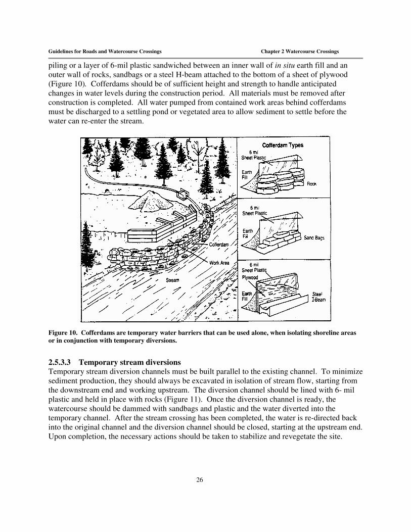
piling or a layer of 6-mil plastic sandwiched between an inner wall of in situ earth fill and an outer wall of rocks, sandbags or a steel H-beam attached to the bottom of a sheet of plywood (Figure 10). Cofferdams should be of sufficient height and strength to handle anticipated changes in water levels during the construction period. All materials must be removed after construction is completed. All water pumped from contained work areas behind cofferdams must be discharged to a settling pond or vegetated area to allow sediment to settle before the water can re-enter the stream.
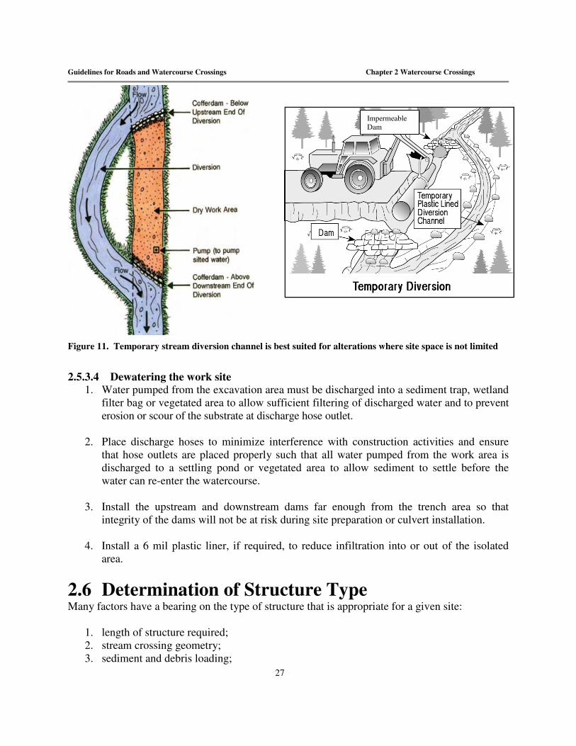
Figure 10. Cofferdams are temporary water barriers that can be used alone, when isolating shoreline areas or in conjunction with temporary diversions. 2.5.3.3 Temporary stream diversions Temporary stream diversion channels must be built parallel to the existing channel. To minimize sediment production, they should always be excavated in isolation of stream flow, starting from the downstream end and working upstream. The diversion channel should be lined with 6- mil plastic and held in place with rocks (Figure 11). Once the diversion channel is ready, the watercourse should be dammed with sandbags and plastic and the water diverted into the temporary channel. After the stream crossing has been completed, the water is re-directed back into the original channel and the diversion channel should be closed, starting at the upstream end. Upon completion, the necessary actions should be taken to stabilize and revegetate the site.
Guidelines for Roads and Watercourse Crossings Chapter 2 Watercourse Crossings
27
Figure 11. Temporary stream diversion channel is best suited for alterations where site space is not limited
2.5.3.4 Dewatering the work site
1. Water pumped from the excavation area must be discharged into a sediment trap, wetland filter bag or vegetated area to allow sufficient filtering of discharged water and to prevent erosion or scour of the substrate at discharge hose outlet.
2. Place discharge hoses to minimize interference with construction activities and ensure
that hose outlets are placed properly such that all water pumped from the work area is discharged to a settling pond or vegetated area to allow sediment to settle before the water can re-enter the watercourse.
3. Install the upstream and downstream dams far enough from the trench area so that
integrity of the dams will not be at risk during site preparation or culvert installation.
4. Install a 6 mil plastic liner, if required, to reduce infiltration into or out of the isolated area.
2.6 Determination of Structure Type Many factors have a bearing on the type of structure that is appropriate for a given site:
1. length of structure required; 2. stream crossing geometry; 3. sediment and debris loading;
Impermeable Dam

Guidelines for Roads and Watercourse Crossings Chapter 2 Watercourse Crossings
28
4. terrain stability; 5. magnitude of the Q100; 6. presence of important fish habitats; 7. economic feasibility; 8. human safety. The design and choice of an acceptable structure is based on the technical and economic feasibility of the structure to pass fish, as well as on the structure’s ability to meet other environmental objectives such as protection of important fish habitats and prevention of erosion and sedimentation. A final choice is based on an evaluation of costs and the ability to meet the hydrological and hydraulic design criteria for the site. This process is only shortened in situations where the alternative is obvious, such as where an open-bottomed culvert spans the entire stream, stream size or terrain conditions dictate a bridge, or the site is flat (<0.5% gradient) and culvert sizing maintains the natural channel width.
2.7 Determination of “Fish-bearing” Streams The Canada Fisheries Act makes it mandatory that safe passage for fish be provided on all “fish bearing” streams. Safe fish passage is the free movement of fish in and about streams, lakes, and rivers – passage that is needed by fish in order to complete critical phases of their life cycles. Adult fish commonly migrate to spawning areas that are located upstream and downstream from stream crossing structures, while juvenile fish often depend on making local moves to rearing or over-wintering areas. All watercourses are to be classified as “fish bearing” unless otherwise proven by the following documentation which must be submitted and reviewed by the regional fisheries biologist:
1. Written description of the habitat present 2. Photographs at the proposed crossing both upstream and downstream of the site 3. Any existing fisheries inventory
2.7.1 Design Options for Fish Passage Designing a structure for fish passage can be a complex undertaking. Basic design requires understanding fish passage criteria, the hydraulics of watercourse crossing structures, and the best way to match these factors with the physical characteristics of a site. Fisheries agencies prefer the use of bridges or bottomless culverts on fish streams because they retain the natural streambed by spanning the stream (Figure 14, Figure 15). Historically, the most frequently used stream crossing structures on forest roads are pipe culverts and these are associated with some of the most common fish passage problems. However, with proper engineering, many problems associated with improper design and construction of culverts

Guidelines for Roads and Watercourse Crossings Chapter 2 Watercourse Crossings
29
can be mitigated, making them viable environmental and economic options. The ability of a fish to pass through a culvert is limited by the following factors: 1) entrance conditions 2) water depth and velocity of flow 3) culvert length and slope 4) fish swimming ability The minimum water depth required for a fish to swim is considered to be 15 - 23 cm. Fish swimming speed must exceed the water velocity for it to be able to pass through a culvert. Fish swimming ability will vary depending on species, size, water quality and hydraulic conditions, but generally, the following guidelines apply: 1) for a culvert which is less than 25 m in length, the average water velocity should not be
higher than 1.2 meters per second 2) for a culvert greater than 25 m in length, additional fish passage measures may be required
based on site specific conditions. If the slope of the invert of the culvert is greater than 0.5%, fish passage becomes difficult and detailed plans are required.

Guidelines for Roads and Watercourse Crossings Chapter 2 Watercourse Crossings
30
2.8 Determination of Required Opening Size The minimum capacity for culverts and bridges in New Brunswick is based on a 100 year return period flow (Q100), which means that the waterway opening should be large enough to accommodate a peak flow or flood which has a 1% chance of occurring in any given year. A physiographic rule is used to determine peak flow in New Brunswick. This method has been developed from an analysis of all the peak flows data from measured streams in a given region. The physiographic rule is a simple equation that relates peak flow to the size of the area drained, modified by some constant value that compensates for regional differences in runoff generation. Once the flow is determined, it is only a matter of matching the correct size of structure using the nomographs (Appendix D).
Figure 12. Using a map with contour intervals, the drainage area of any point in a watercourse can be found by connecting the highest points of land, surrounding the watercourse and tributaries, upstream of that point. This area is then converted into flow (cfs) and opening size can be determined from a nomograph or table (Appendix D)

Guidelines for Roads and Watercourse Crossings Chapter 2 Watercourse Crossings
31
Figure 13. Determination of appropriate watercourse crossing structures
2.8.1 Bridges Bridges have the least impact on fish passage and aquatic habitats of all watercourse crossing structures when designed and constructed with abutments that do not constrict the stream channel width. Clear span designs maintain the stream channel profile, do not alter stream gradients, and readily pass sediment and debris. Bridges do not require fish passage analyses, but still need to be designed to meet Q100. Common types of bridges range from log stringer bridges with timber decks to steel girder bridges. Various techniques are used to support bridges, including log cribs, steel pipes, steel bin walls, cast-in-place concrete or pre-cast lock block walls, timber, and piers where practical, in-stream piers should be avoided. Decisions to use a bridge over a culvert are based on economics, engineering, site parameters including significant habitats such as spawning locations, environmental factors, fish passage requirements (stream gradient), hydraulic and maintenance requirements. Bridges are also less prone to beaver problems and are chosen over culverts in many areas where beavers are a significant concern. A typical permanent bridge installation is shown in Figure 14. The steps below outline general installation guidelines for the construction of bridges: 1) Bridges should be built with wood having a long life span, such as cedar, tamarack, or
hemlock.
Calculate drainage area upstream from proposed
watercourse crossing
Drainage area< 600 ha Drainage area > 600 ha
Use nomograph or Table 2 to calculate culvert size required to carry Q100
Fish passage required?
Yes No
Slope < 0.5% Slope > 0.5%
Install culvert at slope Install bottomless structures: bridges, arch or box culverts
Design Fish Passage (DFO input required)
Install culvert at natural gradient
Permit required from Dept. Environment & Local Government

Guidelines for Roads and Watercourse Crossings Chapter 2 Watercourse Crossings
32
a) Pressure treated lumber, such as that treated with creosote or pentachlorophenol (pentox) should not be used below the normal high water line. Lumber used above the normal high water line which has been pressure treated, such as with chromated copper arsenate (wolmanized), must be cured on dry land in such a manner as to expose all surfaces to the air for a period of at least 21 days prior to construction.
2) Locate bridge abutments back from the stream channel so that excavation and backfilling do
not encroach on the observed high water mark of the stream. The span should not constrict the natural flow of the water and be of sufficient size to handle expected flood flows.
3) Where possible, operate all equipment from the top of the stream bank and use silt fences to
isolate the work area and contain sediments from the work site during construction and installation. Machinery should not be stationed in the wetted portion of the channel.
4) A cofferdam must be constructed to divert flow to the opposite side of the channel while
work is in progress. 5) Where water seepage is encountered during excavation before a sound foundation has been
reached, consider deepening the excavation and backfilling it with compacted shot rock. 6) Crib abutments should be built of squared timbers and may feature an open or closed “face”.
Closed faced cribbing is more effective in preventing backfill material from entering the watercourse because there are no gaps between successive timbers. Crib abutments should: a) rest on a firm foundation such as bedrock, rock ledge, or a layer of well compacted gravel
at least 15 cm (6 in) thick. In very soft soil conditions, the foundation may have to be excavated to a depth of 60 to 90 cm (2 to 3 ft) to provide adequate footing for crib abutments;
b) be located at, or outside, the normal stream banks to minimize the need for instream excavation and to prevent "bottle necking" of stream flow;
c) be aligned so that they do not direct water flow into the banks of a watercourse; d) be set below the possible depth of scour. Scour damage, or undercutting of the abutment,
can be greatly reduced by setting the abutment and its wingwalls at least 30 cm (12 in) below the streambed bottom;
e) not be backfilled with sand or silt, especially if using an open-faced crib abutment. Generally, rock or gravel makes the best backfill material for crib abutments;
f) be constructed so that one abutment is completed before the other is started. 7) Place sills on top of the crib to support the stringers. Sills are made by placing a second face
timber, or bearing plate, just behind the top face timber. The bearing plate should be bevelled flush with the wingwalls.
8) Butt plates placed on blocking located behind the sills, should be built at both ends of the
stringers to prevent them from sliding over the sills. 9) Stringers should be laid across the abutments to support the weight of the bridge, and the

Guidelines for Roads and Watercourse Crossings Chapter 2 Watercourse Crossings
33
traffic it will carry. Stringers should be placed parallel to the direction of the road and should extend onto each abutment at least 45 cm. The exact number and size required will depend on the bridge design, but generally should not be less than 15 cm square nor placed more than 0.5 meters apart. Use only sound, defect-free wood.
10) Cross-decking should be placed perpendicularly across the stringers. Cross-decking should
be evenly spaced along the stringers with an equal overhang beyond the outside stringers. 11) Travel planking is placed on the decking to serve as a travel surface for wheeled traffic. It
generally consists of boards at least 5 cm thick, with two or more boards placed side by side to form "tracks" of suitable width and spacing for the type of traffic to use the bridge.
12) A length of timber or curbing should be laid along the outside edge of the bridge. 13) A railing may also be placed along each side of the bridge as a guide for traffic. A light
reflector attached to the railing is an important safety feature if the bridge is to be used at night.
14) Riprap or wingwalls must be placed at both the upstream and downstream sides of the bridge
to help prevent erosion. Place riprap along streambanks, under the bridge, and upstream and downstream of the bridge where erosion is possible. Riprap should extend above high water level and should be of a size to resist predicted velocities of stream flow.
15) Wingwalls should be held in place by tie-backs, to ensure they are not pushed into the stream
by the weight of the backfill. Wing walls provide assistance for erosion control, bank stabilization and structural integrity
16) Exposed soil must be stabilized against erosion as soon as possible to reduce siltation of the
watercourse. If the installation takes more than one day the exposed soil should be stabilized at the end of each day. Seeding guidelines are provided in Appendix C. Hay mulch, where used, should be applied at a rate of one bale per 25 m2 and be spread uniformly over the entire exposed area.

Guidelines for Roads and Watercourse Crossings Chapter 2 Watercourse Crossings
34
Figure 14. Parameters for calculating waterway opening of a bridge.
2.8.1.1 Bin wall abutments Galvanized steel bin wall abutments can be used instead of the standard treated timber crib. The galvanized steel coating ensures long term maintenance free performance. Bin wall abutments can be assembled at an alternate site and transported to the construction area. The bin walls require well-compacted material inside the bins with a cement pad used for the bearing plate. Bin walls must be founded on an adequately prepared foundation because steel members can be over-stressed and crack if significant settling occurs. The parts have to be aligned precisely before each bolt can be inserted which can be difficult on an uneven foundation. Extra parts should be onsite to prevent costly delays. Bin-wall structures may require larger equipment for installation. 2.8.2 Bottomless Culverts Open bottom structures including squared timber and steel arch culverts are similar to bridge structures, generally spanning the entire streambed and minimizing impacts to the natural stream channel (Figure 14). They are a good alternative where fish habitat concerns or road fill height limitations prevent the use of a conventional round pipe culvert. Steel arches come in various spans and shapes ranging from low to high profiles and arch- to box-shaped. Bottomless structures are vulnerable to underscouring and must be placed on non-erodible fills, keyed into bedrock or till or oversized to ensure footings are not subject to scouring. Installation, post-construction site stabilization and revegetation are much simplified compared to that for metal culverts. 2.8.2.1 Advantages Bottomless culverts provide unrestricted passage for all size classes of fish by retaining the natural streambed and gradient. Water velocity is not significantly changed, and they can be designed to maintain the normal stream width. Wide spans enable passage of high flows without significantly increasing water depth. Low-profile metal culvert shapes are available for reduced
Guidelines for Roads and Watercourse Crossings Chapter 2 Watercourse Crossings
35
road fill heights and box shapes for deeper fills. They usually do not require instream work or machines to cross the stream when the culvert span is within reach of a backhoe. The arch culvert can either be pre-assembled for installation as a unit or assembled in place. The arch design eliminates the problem of pipe bottom corrosion. For temporary installations, the arch design has a higher salvage potential than regular culverts due to thicker steel. 2.8.2.2 Disadvantages Open-bottomed structures are vulnerable to erosion and scouring. The installation time for an arch culvert is more than that required for a bridge, but the arch is maintenance free, thus reducing long-term costs associated with maintenance. 2.8.2.3 Squared timber culverts A typical squared timber culvert is shown in Figure 14. The basic structure of a box culvert is similar to that of a bridge and therefore the approach to construction is also similar. The sidewalls can be considered abutment faces without the wingwalls. Open-bottomed box culverts installed on soft ground should have cross pieces installed approximately every meter to minimize sinking. 2.8.2.4 Bottomless arch culverts Bottomless arch culverts are available with steel plate footings or require concrete footings, either pre-cast or cast in place. Pre-cast concrete footings require limited instream work and may allow the arch to be re-used (e.g. temporary crossing). When footings cannot be embedded, transverse steel cross angles can be installed between the footing plates and the footing set on the streambed. The cross-angles then act as struts to resist the lateral earth pressure. A gravel pad should be prepared to fill in low areas and ensure uniform footing support. Geotextile material should be placed on the outside footing and foundation before backfilling to prevent any future loss of backfill material.
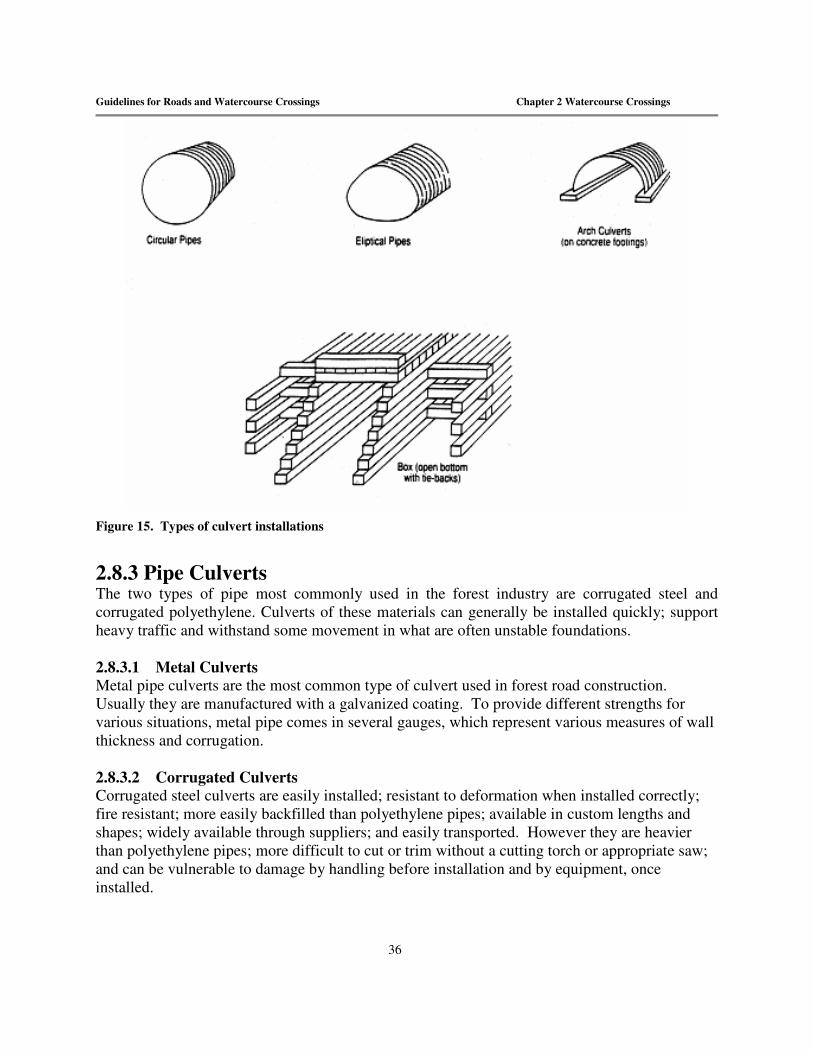
Guidelines for Roads and Watercourse Crossings Chapter 2 Watercourse Crossings
36
Figure 15. Types of culvert installations 2.8.3 Pipe Culverts The two types of pipe most commonly used in the forest industry are corrugated steel and corrugated polyethylene. Culverts of these materials can generally be installed quickly; support heavy traffic and withstand some movement in what are often unstable foundations. 2.8.3.1 Metal Culverts Metal pipe culverts are the most common type of culvert used in forest road construction. Usually they are manufactured with a galvanized coating. To provide different strengths for various situations, metal pipe comes in several gauges, which represent various measures of wall thickness and corrugation. 2.8.3.2 Corrugated Culverts Corrugated steel culverts are easily installed; resistant to deformation when installed correctly; fire resistant; more easily backfilled than polyethylene pipes; available in custom lengths and shapes; widely available through suppliers; and easily transported. However they are heavier than polyethylene pipes; more difficult to cut or trim without a cutting torch or appropriate saw; and can be vulnerable to damage by handling before installation and by equipment, once installed.

Guidelines for Roads and Watercourse Crossings Chapter 2 Watercourse Crossings
37
2.8.3.3 Polyethylene Culverts The use of polyethylene culverts in forest road construction is generally restricted to cross-drains and small stream culverts. A thermo-plastic product manufactured from high-density polyethylene, this type of pipe is typically selected where foundations are stable and materials are well graded. It is also used often in the installation of subsurface drains because it is flexible, lightweight and able to be cut and joined with hand tools. However, they may float away in a washout and are more prone to puncturing than steel if coarse material is used for backfill. The general installation procedure and specifications for culverts are outlined below. A typical culvert installation is shown in Figure 16.
Figure 16. Identification of standards required for culvert installation.
2.8.4 Preparation and Installation of Culverts
1. Excavators and backhoes are used for culvert installation since they create fewer disturbances to the streambed than bulldozers. Do not station machinery in the wetted portion of the channel while carrying out the culvert installation.
2. Install culverts parallel to and as close as possible to the natural stream channel. Culverts set at an angle to the channel can cause bank erosion and develop debris problems (Figure 17).

Guidelines for Roads and Watercourse Crossings Chapter 2 Watercourse Crossings
38
Figure 17. Proper alignment of culvert installations.
3. Install culverts on a firm level bottom, preferably on a bed of gravel 15 to 30 cm thick. The culvert foundation and trench walls must be free of logs, stumps, limbs or rocks that could damage the pipe. If mud or other soft material is encountered at the foundation level, it should be excavated and replaced with a gravel bed at least 60 cm in depth.
4. Place culverts on a uniform slope with the “invert” or culvert bottom set at least 15 cm below the channel bottom at both the upstream and downstream ends.
Culverts placed at bed elevation commonly exhibit many of the past problems associated with lack of fish passage, including excessive drop at culvert outlets (Figure 18), high velocity within culvert barrels, high velocity or turbulence at culvert inlets, and debris accumulation at inlets. Non-embedded culverts are at greater risk of underscouring. This can result in loss of subgrade material and dewatering or perching of the culvert at low design flows. Culverts should be installed on their natural gradients. If the slope of the invert is > 0.5% (a rise or fall of 0.5 cm for every meter of culvert length) fish passage becomes difficult and an engineered design is required (see Section 2.7.1). In soils prone to settlement, culverts may have to be installed with a “camber” or slight rise in the middle of the pipe. Cambering ensures that when the roadbed settles, the culvert will settle to a uniform slope. The middle of the pipe is raised relative to its ends, but not enough to restrict flow. The usual camber requirement is that the centre of the culvert is arched 2.5 cm for every 3 meters of culvert length.
Figure 18. Proper installation of culverts for fish passage.
Culvert Properly Aligned Culvert Improperly Aligned
Waterfall effect creates a barrier
Culvert installed 150 mm below Channel Bottom

Guidelines for Roads and Watercourse Crossings Chapter 2 Watercourse Crossings
39
5. Culverts should be long enough to ensure that the inlet and the outlet cannot become blocked by the encroachment of road embankment fill materials. Extend the culvert a minimum of 0.3 meters beyond the upstream and downstream toe of fill placed around the structure. The exact length will depend on the culvert diameter, the depth of fill over the culvert, the road’s foreslope angle, and culvert’s skew angle or angle between road and stream (Figure 19).
Culvert length as shown in Figure 19 can be determined from the formula: LC = W + 4D (to achieve a 2:1 slope at the culvert opening) where: LC = Length of culvert W = Width of road from shoulder to shoulder D = Depth of fill over the culvert from the bottom of the pipe
Figure 19. Proper installation of culverts to provide adequate fish passage.

Guidelines for Roads and Watercourse Crossings Chapter 2 Watercourse Crossings
40
6. Multiple culvert installations are restricted to two culverts, the invert of one being set 15 cm below the existing channel bottom, while the invert of the other is set at an elevation equal to the streambed (Figure 20). To allow for proper tamping of fill, multiple culverts should be placed a distance of one half the diameter or span apart, or 1 m, whichever is greater.
Figure 20. Multiple culverts are often used to pass high water flows in areas susceptible to flooding. A maximum of two culverts may be installed at any given alteration site
2.8.4.1 Backfilling and compaction For the culvert to adequately and uniformly support the load above it, stable backfill material is vital.
1. Backfill material should preferably be granular to provide good structural performance. Bank or pit-run gravel (less than 5 cm) or coarse sands are recommended. Backfill should not consist of mud, fine sands, silt, large rocks, brush or logging debris as these
Most culvert fill failures are caused by improper backfill material or the lack of adequate compaction.

Guidelines for Roads and Watercourse Crossings Chapter 2 Watercourse Crossings
41
materials encourage wash-out and may cause damage when machinery is driven over the culvert. Soils containing clay must be carefully compacted.
2. Backfill should be compacted thoroughly in layers 10 to 15 cm thick and extend a culvert
diameter on each side of the culvert. Balance fill on either side as fill progresses. Continue placing backfill equally on each side, in uncompacted layers. Compact each layer before adding the next. Generally, no more than one layer difference should be allowed on each side. Even compaction of fill on each side of a culvert gives it the necessary support. Too much fill on one side may cause the pipe to bend out of shape.
3. Most forest road culvert installations require that the elevation of the road surface be a
minimum of one-half the diameter of the culvert over the top of the culvert.
4. Compaction can be accomplished with hand tampers or with mechanical equipment, tamping rollers or vibrating compactors. If mechanical tampers or rollers are used, avoid working too close to the culvert which might cause it to shift or lift. Fill next to the culvert should always be hand tamped.
5. Ensure adequate compaction under haunches (crevices formed where the pipe meets the
bedding). Ensure that backfill material is in firm and intimate contact with the entire bottom surface of the pipe haunches. As the area under the haunches is more difficult to fill and compact, extra care must be taken to prevent voids and soft spots occurring there. Manual placing of material and compaction must be used to build up the backfill in this area.
6. Windrow backfill material on each side of the structure, compacting it firmly with
suitable power compactors.
7. Provide a 300 mm minimum of backfill over the culvert before any traffic crosses over the culvert, to prevent crushing or misshaping. In all cases, heavy equipment should not bear down on the culvert until the compacted fill is complete over the top of the crown.
8. Maintain the manufactured culvert shape. Sufficient compaction should be applied to the
culvert fill so that the pipe will not deflect more than 5% off round. 2.8.4.2 End protection and stabilization 1) Rip-rap and/or headwalls and wingwalls must be placed at both ends of the culvert, to an
elevation of at least one half of the culvert diameter above the culvert, and a minimum of one culvert diameter on each side, immediately upon completion of the culvert installation (Figure 21). Headwalls are vertical walls (wooden, concrete, gabion, etc.) that parallel the road and extend back into the road embankment. They allow shorter culverts to be used and increase the volume of water a given culvert can handle.

Guidelines for Roads and Watercourse Crossings Chapter 2 Watercourse Crossings
42
2) Headwalls may be built with or without wingwalls (vertical walls placed at an angle to the road). Wingwalls increase culvert cost but provide greater bank and road protection.
3) Protect the inlet and outlet side slopes of the road subgrade from erosion and sloughing by
armouring the fill slopes with riprap for a distance of 1.5 diameter (D) on each side of the culvert and toeing into the streambed. Consider extending riprap along any erodible streambank above and below the culvert inlet and outlet, but keep disturbance to only that which is needed to protect fill or prevent blockage of stream flow. a) rip rap should consist of durable quarried or field rock with at least 60% of the rock 0.03
m3 or larger b) geotechnical fabric must be placed behind all material other than squared timber.
4) Inlet and outlet slopes from 0.5 m above the culvert to the road level should be stabilized by one
of the following means: a) vegetated slope - establishment of a vegetated 2:1 slope prior to September 15. b) if the slope (2:1) cannot be stabilized by vegetation by September 15 then other methods
will be required: i) raise the shear walls to the road level; or ii) cover the slope with straw and/or hay (5cm thick) along with seeding or clean rip rap
with geotechnical fabric up to the road level. 5) In fish-bearing streams, the stream bottom and the banks at the outlet end of the culvert
should be protected from scour. If rock is not naturally present in the stream, then a rock apron built of riprap having an average size of 15 cm should be built at the downstream end of the culvert. If required, rock aprons must be in place when the culvert begins to operate and should be built to the following specification: a) Apron width = 3 x culvert diameter b) Apron length = 5 x culvert diameter c) Apron depth = half the culvert diameter
6) Begin revegetating all exposed mineral soil immediately after completing the installation.
Hand seeding, hydraulic seeding and use of various mulches or fibre bonding agents should be considered to speed site recovery. If the installation takes more than one day, exposed soil should be stabilized at the end of each day. Seeding guidelines are provided in Appendix C. Apply hay mulch at a rate of at least one bale per 25m2 and spread uniformly over the entire exposed area.
7) When the new culvert is opened to water, watch for the need to add more rock armour. After
checking the installation, close any dewatering channel.

Guidelines for Roads and Watercourse Crossings Chapter 2 Watercourse Crossings
43
Figure 21. Culvert crossing construction.
2.8.5 Fording Fording is not considered a "routine" means of crossing watercourses. While occasional use of fords may not create significant environmental impacts, the result of continual, extensive or indiscriminate use is streambank and bed damage, changes to channel morphology, diminished water quality and destruction of fish habitat. Although the use of fords is discouraged, these guidelines allow for the use of fords in approved circumstances while ensuring that environmental impacts are minimized. 2.8.5.1 Authorization Fords can only be used, constructed or upgraded where approval has been granted in an approved Operating Plan. 2.8.5.2 Requirements of fords The primary purpose of fords is to provide an erosion-free drivable running surface across a watercourse while at the same time not impeding water flow, causing downstream erosion of the stream, increasing sediment input from the approaches or diverting the stream direction.

Guidelines for Roads and Watercourse Crossings Chapter 2 Watercourse Crossings
44
2.8.5.3 Acceptable use and siting of fords Fords should be considered as the last option for crossing of any watercourse. A well designed temporary crossing is preferred (See Temporary Crossing Section 2.8.6) 1. Fords will have stable approaches and banks with nonerodible substrates firm enough to
support the weight of machinery. However, where damage occurs to banks, approaches and streambeds, mitigation is required (Figure 22).
2. When required during road construction, fording should be limited to only the equipment necessary for the actual construction and should be done at only one location. This should be where the least damage to the watercourse and stream banks will occur. It may be located within the clearing width or outside depending on the site. When moving to a location outside of the clearing width, consideration must be given to habitat values located at the fording site. Sensitive sites such as spawning areas should be avoided where possible or crossed using a temporary bridge.
3. Examples of when the use of fords could be considered include, forest fire suppression, installation or repair of permanent crossing structures, new road construction or right-of-way clearing and emergency situations.
4. Where sedimentation will occur, temporary bridges, small logs underlain with filter fabric, or recycled tire mats may be placed on the bottom of the stream to prevent machinery from contacting the streambed or banks directly.
2.8.5.4 Operating conditions The use of fords must be controlled to ensure that the integrity of the structure is maintained and that any potential impacts on the environment are minimized.
1. Disturbance to ground vegetation will be minimized. 2. The ford should have a maximum width of 1.5 times the width of the equipment crossing
it. 3. Fords are not designed for extraction of any forest products. Nothing that could destroy
the running surface of the ford will be dragged or skidded across it. 4. Vehicles using the ford must be in good working order and not leaking fuel, hydraulic
fluids, lubricating oil or their cargo. 5. All excess soil should be removed from heavy equipment before it fords a watercourse. 6. The ford should not be used if the water depth is greater than the axle height of the
vehicle. 7. Restoration of the site to its original condition (as much as possible) is required
2.8.5.5 Deactivation and restoration of fords Once the use of the ford site is no longer required, the approaches will be decommissioned such that access is no longer available to vehicular traffic. Any material that has been used on the approaches, banks or streambeds that could cause future environmental problems will be removed in a manner and time that will minimize sediment production. Streambeds and banks will be restored to their original condition as much as possible. Every effort will be made to prevent future deterioration of disturbed areas (See Section 2.8.4.2).

Guidelines for Roads and Watercourse Crossings Chapter 2 Watercourse Crossings
45
Figure 22. Stream cross-section of a ford identifying the need for a sufficient dip to ensure water cannot breach the ford and run down the approaches as well as appropriate use of the non-erodible material.
2.8.6 Temporary Crossings Most temporary watercourse crossings are intended to provide short-term access across a stream for the purposes of timber harvesting activities where no further road development beyond the block is planned or can be utilized as a short-term measure in preparation for installation of a permanent crossing structure. Proper use and installation can result in less impact to the aquatic habitat and less disturbance to the bed and banks of the watercourse. Temporary watercourse crossings should not remain in the watercourse during the spring freshet unless approved by the Regional Director. For the purpose of this section, fords are not considered as temporary watercourse crossings (See 2.8.5 Section on Fords). 2.8.6.1 Definition of a temporary crossing Temporary crossings are physical structures placed in watercourses to provide access across a watercourse for a limited period of time, preferably less than 2 months. 2.8.6.2 Planning a) Watercourse crossings should be designed to accommodate the peak flow expected to occur
for the specified period of time that the structure will be in place. b) Permission to install temporary crossings is usually granted for the low flow period in the
summer months but structures can be utilized at other times of the year with appropriate environmental conditions.
c) Structure size can be considerably smaller if the temporary structure is installed and removed before the normal high flow periods in the fall and spring.
Guidelines for Roads and Watercourse Crossings Chapter 2 Watercourse Crossings
46
d) Culverts can be sized based on the Q2 peak flood frequency provided they are installed only between June 1 and September 30 and for a duration not exceeding two weeks.
e) Most temporary structures such as bridges should be installed high on the banks of the watercourse. Providing this method is used, the size of the opening is not critical unless the structure compromises the bankfull channel cross-sectional area.
2.8.6.3 Road construction Temporary crossings installed to allow ROW clearing or road construction in preparation for a permanent crossing installation do not require special permission provided that approval for the permanent installation has been approved in the Operating Plan. However, the Licensee will notify DNR of the temporary installation of the structure. 2.8.6.4 Access for harvesting Temporary crossings installed to provide short-term access across a stream for the purposes of timber harvesting activities where no further road development beyond the block is planned do not require special permission provided that approval for the temporary installation has been approved in the Operating Plan. Because all watercourse crossings require legal approvals, the Licensee must submit a proper amendment to the operating plan including location and type of installation for all installations not previously identified in the approved Operating Plan. Any of the types of temporary watercourse crossings identified in this guideline are acceptable, provided the criteria for use are met. 2.8.6.5 Standard conditions applicable to all temporary crossings a) All temporary crossings will be removed by March 31st unless special considerations were
approved at the DNR regional level and applied at the time of installation. b) Outside of the June 1 - September 30th window, no instream work will be undertaken in
natural watercourses having a channel width > 0.5 m. c) No grubbing or excavating within 10 m of the stream bank, outside of June 1st - September
30th. d) Abutments can be left in place. If they are to be removed, then appropriate precautions and
mitigative measures must be undertaken to prevent siltation of the watercourse. e) All disturbed areas within 15 m of the watercourse must be stabilized immediately after
structure removal. If the structure was removed during winter conditions, the Licensee will revisit the site and undertake additional mitigative measures between June 1 and June 30.
f) Site restoration and stabilization measures are essential upon the removal of temporary structures. All standards and guidelines associated with regular watercourse crossings apply to temporary watercourse crossings (See Chapter 3 "Environmental Protection and Mitigation Guidelines”).
g) When no longer required, temporary crossing structures should be removed as quickly as possible unless environmental conditions dictate otherwise.
h) Temporary structures can only be placed in areas with approach slopes which are less than 25% (approx. 11o).

Guidelines for Roads and Watercourse Crossings Chapter 2 Watercourse Crossings
47
2.8.6.6 Temporary bridge (standard) Criteria: Regular stream crossing situations The stream banks at the crossing location must be firm and level. a) Set abutment or cribs sufficiently back from the top of the stream bank to avoid disturbing
the channel. b) Abutments cannot be constructed of round timber c) A crib made of squared timber must be installed before fill is added to the approaches. Once
the crib is built, geo-textile filter fabric must be laid over the ground and excess provided to cover up the fill so that the fill is entrapped in the fabric and not permitted to enter the watercourse. Ensure cribs are of sufficient length to retain road material.
d) Geo-textile filter fabric must be used to fully cover the stringers to prevent road material from entering the stream.
e) The stringers, cross pieces and decking can be installed separately or as a single unit. f) An excavator or backhoe must be used to remove the stringers, cross pieces and decking. See
general conditions regarding removal of the abutment and squared timber cribs. 2.8.6.7 Runner with single log abutment and decking Criteria: Machine trails with unstable soil conditions and sites where material has a tendency to enter the watercourse through equipment travel (rutting) or road maintenance (grading or snow ploughing) (Figure 23). a) Place 25 to 30 cm (in diameter) timbers parallel to the stream, approximately 1 m back from
the stream bank, to act as abutments. b) Place two pads (runners), constructed from three 25 to 30 cm squared timbers bolted or
chained together, across the stream and secure to the abutments. c) Place decking on the structure to prevent material from entering the stream as a result of
equipment travel or road maintenance. d) Place geotextile material under the decking e) Build up approaches level with the top of the decking. f) If excessive material builds up on the decking, trucking or skidding will cease until
conditions improve or the site is stabilized.

Guidelines for Roads and Watercourse Crossings Chapter 2 Watercourse Crossings
48
Figure 23. Temporary bridge with single sill log
2.8.6.8 Runners with single log abutment and no decking Criteria: Restricted to winter operations where no road is required and the skid trails are stable; also, summer porter trails; no skidding of timber across the structure. a) Place 25 to 30 cm (in diameter) timbers parallel to the stream, approximately 1 m back from
the stream bank, to act as abutments. b) Place two pads (runners), constructed from three 25 to 30 cm squared timbers bolted or
chained together, across the stream and secure to the abutments. c) Build up approaches level with the top of the pads. d) If disturbance occurs, operations will cease until the site freezes. 2.8.6.9 Round timber crossing Criteria: Winter operations on natural watercourses having bank to bank measurements less than 0.5 m in width; for use by harvesting equipment only.
a) Place large round timber parallel to the stream approximately 1 m back from the stream bank
to act as abutments. b) Place even sized round timber cross-pieces long enough to span from abutment to abutment
along the entire width of the crossing. c) Place geo-textile fabric over the entire structure extending 1 to 2 m beyond the abutments. d) Softwood brush and tops may be placed over the surface of the structure. e) Fill structure even with road surface with snow.

Guidelines for Roads and Watercourse Crossings Chapter 2 Watercourse Crossings
49
2.8.6.10 Portable bridges (including pre-fab bridges, rail cars, flatbed trailers, etc.) Criteria: Most watercourse crossing situations; not for use on spans exceeding 10 m. a) The structure must be lifted into place and not dragged across the watercourse and lifted out.
However, if the structure is removed in the winter, it can be dragged across the ice and snow providing there is no danger of stream or ground disturbance.
b) It should be placed on or above the banks on a sill log or crib abutment. c) Material (snow or fill) can be placed at the end of the structure for the approaches. d) No ground disturbance is permitted. 2.8.6.11 Ice bridges Ice bridges provide winter access to normally inaccessible areas. Ice bridges are effective stream crossing structures for larger streams and rivers, where the water depth and stream flow under the ice are enough to prevent the structure from coming in contact with the stream bottom ("grounding") and there are no concerns regarding spring ice jams. Grounding can block stream flow and fish passage and cause scouring of the stream channel. The following steps outline the general installation procedure for ice bridges: a) Choose a location where the stream banks and approaches have little or no slope. b) Sites where water levels fluctuate, springs seeps are present, or the watercourse is narrow and
fast flowing are not acceptable. c) Snow should be packed down over approaches to help minimize bank disturbance. d) Clearing of the right-of-way approach must be kept to a minimum and brush and debris must
be placed so that it will not enter the watercourse. e) Construct approaches of clean compacted snow and ice to a thickness that will adequately
protect streambanks and riparian vegetation. Where limited snow is available, large gravel material could be used to build up approaches.
f) To begin ice bridge construction, clear the snow from the natural ice at the crossing location. g) Pump water onto the ice and allow it to freeze until a depth of about 25 cm is achieved. The
construction of the ice bridge should progress slowly and in individual layers or steps not exceeding 2.5 cm thick per freeze. Total ice bridge thickness can reach up to 1.5 m.
h) Coniferous logs with diameters of at least 25 cm can be placed on the ice pad parallel to the road and spaced about 1 m apart, across a road width of 5-6 m. The logs can be placed end-to-end along the entire length of the ice bridge and then flooded with water and frozen in place. Flooding and natural ice build-up beneath the logs takes about two to three weeks to provide an ice bridge thickness of about 1 m. All timbers will be removed before the spring thaw to prevent it from entering the watercourse.
i) Sand, brush and woodchips are not to be used in the construction of the ice bridge. j) Begin ice bridge deactivation while the structure is still safe for personnel and equipment.
All debris and dirt should be removed and placed at a stable location above the high water mark of the stream and prevented from eroding. All logs within the structure that can be safely removed should be removed. The ice can be broken using an excavator, backhoe or other methods as long as no disturbance to the streambed or bank occurs.

Guidelines for Roads and Watercourse Crossings Chapter 2 Watercourse Crossings
50
2.8.6.12 Safety a) The crossing must be checked on a daily basis during use for deep cracks that are dangerous
and heavy loads are not permitted until they are repaired. b) For safety, ice bridge approaches should be kept to grades of six per cent or less. c) For added safety and to fill in stress and expansion cracks, it is a good idea to have water
trucks or pumps routinely flood the bridge.
Table 1. Recommended ice thickness for various activities during winter operations.
Permissible Ice Thickness * cm
One person on foot 5.0 Light truck (2.5 tons gross) 20.3 Medium truck (3.5 tons gross) 25.4 Heavy truck (7-8 tons gross) 30.5 10 tons 38.1 25 tons 50.8 45 tons 63.5 70 tons 76.2 110 tons 91.4 * Clear blue river ice reduces carrying capacity by 15%, and 50% for slush ice Temporary Culverts Criteria: Limited use (temporary bridges preferred); maximum 2-week duration between June 1st and September 30th.
1. Culvert can be sized for the Q2. 2. Culvert must be installed in the dry. 3. All material must be on-site before construction begins. 4. Stream banks and bed must be restored immediately upon removal.
Snow Culverts Criteria: Skid trails only; watercourses less than 0.5 m in width as measured from bank to bank; high stream banks required (minimum height = diameter of the pipe); stream must be open (no ice cover); streambed must be level and straight for the entire length of the culvert. Construction
1. Place culvert in open stream. 2. Pack slush around culvert and freeze. 3. Build approaches with snow and freeze. 4. Only snow is to be used as fill around the culvert. 5. Culvert is to remain in place until after spring thaw and the culvert must be removed from
the channel in the spring.

Guidelines for Roads and Watercourse Crossings Chapter 2 Watercourse Crossings
51
6. No disturbance of the streambed is permissible; if any disturbance occurs, operation must cease until the site freezes.
7. Culvert must be secured to a permanent structure such as a tree. Road Closure and Recreational Uses
1. Upon removal of the temporary structure, the road must be blocked and proper signage
installed to warn people that the crossing has been removed. 2. In the event that recreational traffic may still utilize the crossing, a stable ford should be
constructed if the streambed and banks are not firm and stable. This can be accomplished by using brush mats and rocks on the bank and gravel placed within the stream.

Guidelines for Roads and Watercourse Crossings Chapter 3 Erosion and Sedimentation Control Measures
52
3 Erosion and Sedimentation Control Measures
3.1 Introduction Forestry activities such as road construction and watercourse crossings have the potential to result in harmful alterations to fish habitat and degradation of water quality within the vicinity of the stream crossing and downstream. It is not possible in many situations to construct stream crossings without creating some sedimentation and disturbance. However, many problems can be avoided through good planning, the timing of construction activities so as to avoid sensitive periods, and the application of best management practices before, during, and after construction. Environmental impacts associated with the construction, installation and use of stream crossings can be avoided or mitigated by best management practices that are directed toward meeting the following objectives:
1. Eliminating or reducing sediment-related problems and preventing deleterious substances from entering streams during installation
2. Minimizing or avoiding disturbance to stream channels
3. Revegetating and stabilizing the site to prevent post-construction erosion; and,
4. Regular maintenance of the structure
3.2 Ground Vegetation near Watercourses Retaining vegetation intact within the road clearing width is one of the most effective methods of preventing erosion and minimizing disturbance to fish habitat. Where vegetation does not conflict with road traffic and safety needs, retain as much natural vegetation as possible within the full width of the right-of-way. Where leaving shrubs in place results in road hazard problems, particularly with visibility at bridge sites, shrubs and standing trees should be removed and grasses and legumes promoted to keep brush down and visibility high. At no time however, is grubbing permitted within the restricted work zone adjacent to watercourses unless immediately underlying the proposed road surface.
3.3 Slash and Debris 1. All slash and debris that enters the stream channel must be removed concurrently with
site development. 2. This material should be placed where it cannot be re-introduced into the stream by
subsequent flood events. On most streams, this is above the elevation of the active floodplain.

Guidelines for Roads and Watercourse Crossings Chapter 3 Erosion and Sedimentation Control Measures
53
3. Stream cleaning should not result in the removal of any hydraulically stable natural debris.
3.4 Erosion and Sediment Control Measures The Forest Management Manual requires that all culverts installed in natural watercourses greater than 0.5 m in width will occur in the dry. The amount of sediment generated at a stream crossing is directly related to the sensitivity of the soil to erosion, the amount of area exposed to runoff or stream flow, and the disturbance caused by felling and removal of trees from the clearing width. The following are common methods for reducing erosion during and after construction:
1. Retaining existing vegetation 2. Keeping water off the site 3. Isolating the work area 4. Working from the top of the bank 5. Using sediment traps 6. Silt fences and hay bales 7. Stabilizing fills 8. Revegetating exposed soils, and 9. Using many of the new geotextile fabrics or fibre bonding systems to improve
revegetation success 3.4.1 Isolating the Work Site Working in the dry can greatly reduce the amount of sediment produced during construction and facilitate construction. Cofferdams, flumes, and temporary stream diversions can be used to isolate construction sites so that work can proceed in the absence of stream flow. See "Watercourse Crossings Guidelines" Chapter 2. 3.4.2 Sediment Traps and Silt Barriers Silt fences, straw bale dikes, sediment traps and geotextiles provide effective means for controlling sediment during construction. Sediment traps and basins (Figure 24) can be either simple, small pits or large, complex engineered structures designed to impound large quantities of sediment. Sediment traps used on forestry roads are generally small, excavated pits that capture coarse sediments from ditchlines before they can enter a stream. Silt fences and straw bales, in contrast, are designed primarily to intercept and filter small volumes of "sheet flowing," sediment-laden runoff. Used singularly or in combination, they can isolate construction areas and trap sediment close to the source of production. All sediment traps and barriers must be cleaned frequently while they are in place if they are to be effective.

Guidelines for Roads and Watercourse Crossings Chapter 3 Erosion and Sedimentation Control Measures
54
Figure 24. Layout of a sediment trap.
3.4.3 Silt Fences Silt fences are short-term structures constructed of wood or steel fence posts and a suitable permeable geotextile (Figure 25). They retain soil on the site and reduce runoff velocity across areas below the fence. Silt fences work predominantly by reducing velocity. Silt fences are effective boundary-control devices and can be used to intercept soil from cutslopes and ditchlines, and to isolate the general work area from the stream. Silt fences are most effective when areas draining to the barrier are 1 ha or less. They are not intended for use in streams, or in ditches that receive excessive flow.
Figure 25. Silt fence installation showing wire support for filter fabric and backfilled trench.

Guidelines for Roads and Watercourse Crossings Chapter 3 Erosion and Sedimentation Control Measures
55
Geotextiles for silt fence construction come in different styles and grades, each with specific characteristics. Depending on the strength of the filter fabric used, and spacing of support posts, the fabric may or may not require wire mesh support backing. The manufacturer’s design and installation specifications should be followed closely with respect to the need for support backing and spacing of support posts. If these specifications are not known, then it is important to ensure that support posts are not more than 300 cm apart and that the geotextile is supported by wire mesh. When extra-strength fabric is used, wire support is not necessary, provided posts are not more than 180 cm apart. Some silt fence materials come with an integrated drawcord which allows the material to be drawn taut after installation. This improves durability and performance. Silt fence material can be cleaned and re-used. Silt fences are an effective, but commonly misused sediment control measure. They are all too often poorly located and installed. Where they are not properly maintained, they can fail, creating more damage than if no barrier had been installed. The need for proper siting and secure installation of silt fences cannot be overstated. Trenching, firmly setting posts, and securely stapling wire and fabric in place are key construction details. Common causes of poor installation are the lack of a trench and not burying the bottom edge of the material. The following steps outline the recommended procedure for installation of a silt fence:
1. Set posts along a line that marks the position of the silt fence. 2. At stream crossings silt fences may be used to intercept surface drainage from the
approach ditch line or disposal areas, or used to isolate the entire work site.
3. In ditchlines, curve the fence line upstream at the sides to direct the flow toward the middle of the fence. The sides should be higher than the centre.
4. Posts should be spaced a maximum of 300 cm apart and driven at least 30 cm into the
ground until firmly secure. Posts can be either 10 cm diameter wood or steel with a minimum length of 150 cm.
5. Excavate a trench approximately 30 cm deep along the line of posts and upslope of the
barrier.
6. Fasten wire mesh securely to the upslope side of the posts when using standard weight filter fabric.
7. Use heavy-duty wire staples at least 25 mm long and tie wires or hog rings to fasten the
fabric to the posts. The bottom of the wire mesh is folded into the trench.

Guidelines for Roads and Watercourse Crossings Chapter 3 Erosion and Sedimentation Control Measures
56
8. When extra-strength fabric is used, spacing between posts can be longer and wire mesh backing is not needed.
9. Fasten the filter fabric on the uphill side of the fence posts and extend it 15-20 cm into
the trench.
10. Fence height should not exceed 90 cm.
11. Avoid making joints by using fabric from a continuous roll. Splice all joints at posts with good overlaps.
12. Backfill the trench over the toe of the fabric and compact the soil.
3.4.4 Straw Bales Straw bales have the same limitations as silt fences with regard to siting and will only last for approximately 3 months. Like silt fences, straw bales must be properly installed to be effective (Figure 26). Straw bales can be installed to intercept sheet flow runoff at the base of an exposed cutbank or swale, or as a check dam in the approach ditch line of a road. The installation procedure is similar to that of silt fences in that proper trenching and staking are required. Straw bales can result in the spread of noxious weeds and non-native grasses. As with silt fences, straw bale dikes have been widely misused. Bales not staked to the ground, not trenched, not abutted tightly, not having enough space for entrapment and cleaning, and not centered in the flow path will not function adequately. The following steps outline the general installation procedure recommended for using straw bales. The procedure can be adapted for different applications:
1. Excavate a trench approximately 10 cm greater than the width of a bale and the length of the proposed barrier. The barrier should follow the slope contour.
2. If the barrier is at the toe of a cutslope, place it 150-180 cm away from the slope if
possible. This placement provides access for maintenance and space for soil to collect. 3. Place bales in the trench with their ends tightly abutting. A tight fit is important to
prevent sediment from escaping through the spaces between the bales.
4. All bales must be either wire-bound or string-tied.
5. Position bales so that the bindings are oriented around the sides rather than along the tops and bottoms.
6. Securely anchor each bale by driving at least two stakes through the bale. Wood stakes
are the best, but rebar can be used.
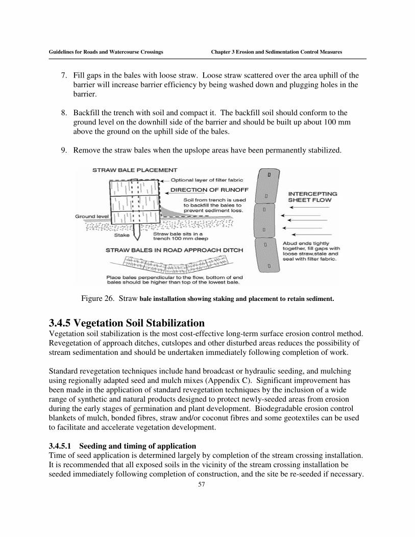
Guidelines for Roads and Watercourse Crossings Chapter 3 Erosion and Sedimentation Control Measures
57
7. Fill gaps in the bales with loose straw. Loose straw scattered over the area uphill of the
barrier will increase barrier efficiency by being washed down and plugging holes in the barrier.
8. Backfill the trench with soil and compact it. The backfill soil should conform to the
ground level on the downhill side of the barrier and should be built up about 100 mm above the ground on the uphill side of the bales.
9. Remove the straw bales when the upslope areas have been permanently stabilized.
Figure 26. Straw bale installation showing staking and placement to retain sediment.
3.4.5 Vegetation Soil Stabilization Vegetation soil stabilization is the most cost-effective long-term surface erosion control method. Revegetation of approach ditches, cutslopes and other disturbed areas reduces the possibility of stream sedimentation and should be undertaken immediately following completion of work. Standard revegetation techniques include hand broadcast or hydraulic seeding, and mulching using regionally adapted seed and mulch mixes (Appendix C). Significant improvement has been made in the application of standard revegetation techniques by the inclusion of a wide range of synthetic and natural products designed to protect newly-seeded areas from erosion during the early stages of germination and plant development. Biodegradable erosion control blankets of mulch, bonded fibres, straw and/or coconut fibres and some geotextiles can be used to facilitate and accelerate vegetation development. 3.4.5.1 Seeding and timing of application Time of seed application is determined largely by completion of the stream crossing installation. It is recommended that all exposed soils in the vicinity of the stream crossing installation be seeded immediately following completion of construction, and the site be re-seeded if necessary.

Guidelines for Roads and Watercourse Crossings Chapter 3 Erosion and Sedimentation Control Measures
58
The use of a mulch can be beneficial in extending the spring growing period, and in preventing early frost damage. Caution is advised when considering applying fertilizer in some watersheds as there may be restrictions on use; check with DELG before using in community watersheds. 3.4.5.2 Seeding with hay mulch Mulching significantly improves seedling establishment. Mulching accelerates seedling development and reduces seed loss due to rainfall and runoff. When combined with hand broadcast seeding, hay is a fast and cost-effective method for dealing with smaller exposed areas near stream crossings. Seed and mulch can be applied by hand, independent of the seeding schedule or the method established for the rest of the road system. This practice will jump-start revegetation at these higher-risk locations. When hay is used for mulch, it should not be applied too heavily. Soil should be visible through the hay mat; this will allow the seedlings to penetrate. Hay can be applied mechanically, though for limited use near streams, hand application is an appropriate method. 3.4.5.3 Hydraulic seeding and mulching Hydraulic seeding is the most efficient means for seeding. It is a one-step method for spraying a slurry of seed, fertilizer, wood fibre mulch, and water. The critical factor is the ability of the mulch to hold in place during rainfall and wind. Wood fibre is a preferred mulch for hydroseeding applications, as it is relatively inexpensive and readily available, but it does not provide much erosion protection because it lacks enough mass to absorb the energy of raindrops or flowing water. Its primary function is to assist plant establishment by retaining soil moisture and holding seeds in place. 3.4.5.4 Fibre-bonding agents A fibre-bonding agent is an hydraulically applied slurry of wood fibres and tackifiers that conform to the ground and dry to form a durable, continuous erosion control blanket that stays in place until vegetation is established. This slurry is composed of long-strand, thermally produced wood fibres that are held together by organic tackifiers and mineral bonding agents which, upon drying, become insoluble and non-dispersible. Once dry, the bonded matrix can be rewetted repeatedly and will hold seed in place without washing away. Because they are adhesive, they provide an erosion-resistant layer that protects the surface of most soil surfaces—including steep slopes—with no gaps in total coverage. The fibre mats created are biodegradable and decompose slowly as vegetation is re-established. Like other forms of mulching, bonded fibre matrices hold seed and fertilizer in place, yet allow sunlight and plants to penetrate. Compared to conventional erosion control blankets, they require no manual labour to install and are not subject to under-rilling or tenting, as can occur with erosion control blankets (see below). 3.4.6 Erosion Control Blankets and Netting Erosion control revegetation matting (ECRM) or seed overlain with a biodegradable netting material such as jute (woven fibres) are other effective methods for speeding germination, plant growth, and holding materials in place

Guidelines for Roads and Watercourse Crossings Chapter 3 Erosion and Sedimentation Control Measures
59
(Figure 27). The former are pre-seeded mats that contain seed and fertilizer. They are held in place by stakes and can be made to overlie most slope angles adjacent to stream crossings. Other forms of netting material, such as woven jute, may be used to hold mulch and other materials in place. This type of netting provides little if any soil protection but holds seed and mulch in place.
Figure 27. Procedure for using fibre mats to speed revegetation adjacent to road approach slopes.
Both methods must be applied in such a way that they are in complete contact with the soil. Otherwise, erosion can occur beneath the netting. Unlike hydraulically applied fibre-bonding agents, they are more labour-intensive. 3.4.7 Riprap Riprap or shot rock should be placed at the outlet of all cross-drains where ditchwater is being diverted from an approach ditchline and discharged onto erodible soils or fills. Ditches lined with riprap, shot rock, or large gravel are an effective method for reducing erosion at approaches to stream crossings. Riprap slows the velocity of ditchwater and armours erodible ditch bed materials. All riprap or rock used should be free of silt, overburden, debris or other substances deleterious to fish. The material should be durable and sized to resist movement by stream flow.
3.5 Drainage Control See "Forest Road Planning Construction Guidelines" Chapter 1, Section 1.5 Control of Surface Water
3.6 Handling Hazardous Substances It is important to know and comply with all regulations governing the storage, handling, and application of substances that can be deleterious to fish, including wood preservatives, paints, fuel, lubricants, and fertilizers. Wood preservatives containing creosote, cholorophenols, zinc or copper are extremely toxic to fish and should not be used where it will be subject to contact with

Guidelines for Roads and Watercourse Crossings Chapter 3 Erosion and Sedimentation Control Measures
60
the stream. Pressure-treated wood should be allowed to weather for a minimum of 21 days before use. All paints and preservatives should be applied to materials off-site and allowed to cure before being used in construction. Uncured concrete can kill fish by altering the pH of the water. Pre-cast concrete should be used whenever possible, to eliminate the risk to fish. When cast-in-place concrete is required, all work must be done in the dry and effectively isolated from any water that may enter the stream for a minimum period of 48 hours. All fuels, lubricants, and any other toxic materials must be stored outside the designated buffer on the stream, in a location where the material can be contained and prevented from entering a stream. Equipment should be checked for leaks of hydraulic fluids, cooling system liquids, fuel, and be clean prior to fording. All fuelling should be done outside of the buffer. A contingency plan should be developed for the use of all hazardous materials, including spill containment, clean-up, and notification of the appropriate federal and provincial agencies in the event of a problem. Where bridge decks require cleaning, precautions must be taken to ensure that deleterious material including sand and gravel do not enter the stream.

Guidelines for Roads and Watercourse Crossings Glossary
61
Glossary Abandoned Road
A forest or logging road that is permanently closed, stabilized, and no longer passable by vehicles. DNR must approve abandonment of any roads.
Abutment A wall or mass supporting the end of a bridge, arch or span, and sustaining the pressure of the abutting width.
Bottomless Arch culvert
A type of culvert which has an arch shape, open bottom and rests on foundations of concrete or steel plate footings. The curved structure is designed to exert horizontal forces on it supports when subjected to vertical loads; commonly used as a bridge.
Armouring Placing rock on headwall or fill material around a culvert to prevent water from eroding and undercutting the culvert and flowing under the road.
Backfill Fill used to replace material removed during construction of a structure such as a bridge or culvert.
Baffle A structure built or placed on the bed of a stream or culvert bottom, the purpose of which is to deflect, check or dampen stream flow. Used to facilitate fish passage.
Bankfull width The width of a river or stream channel between the highest banks on either side of a stream.
Bedrock (Geology) The solid rock beneath the soil (Zone of Aeration or Zone of Saturation) and superficial rock. A general term for solid rock that lies beneath soil, loose sediments, or other unconsolidated material.
Berm An artificial ridge or earthen embankment used to retain or redirect water flow.
Bog Freshwater wetlands that are poorly drained and characterized by a buildup of peat.
Borrow Pit Excavated material along the road right-of-way or from pre-cut pits outside the road right-of-way, to be used in the subgrade or grade of the road.
Box culvert A culvert, usually constructed of squared timber, which has a rectangular or square cross-section.
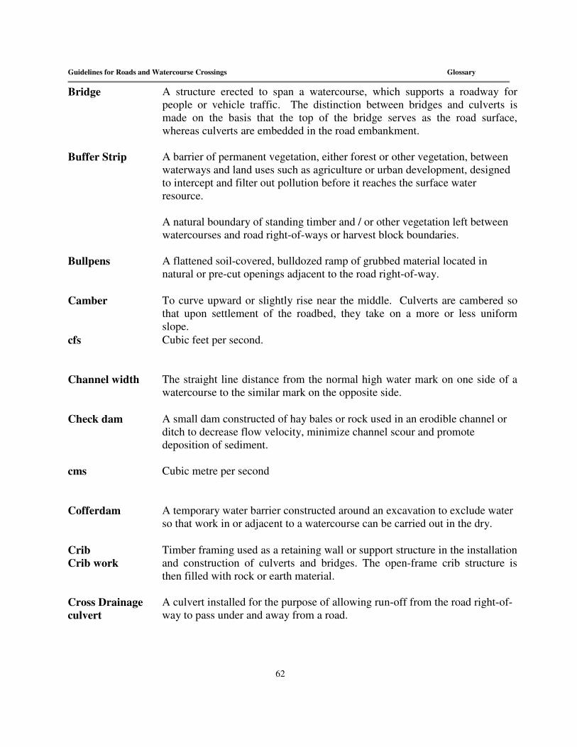
Guidelines for Roads and Watercourse Crossings Glossary
62
Bridge A structure erected to span a watercourse, which supports a roadway for people or vehicle traffic. The distinction between bridges and culverts is made on the basis that the top of the bridge serves as the road surface, whereas culverts are embedded in the road embankment.
Buffer Strip A barrier of permanent vegetation, either forest or other vegetation, between waterways and land uses such as agriculture or urban development, designed to intercept and filter out pollution before it reaches the surface water resource. A natural boundary of standing timber and / or other vegetation left between watercourses and road right-of-ways or harvest block boundaries.
Bullpens A flattened soil-covered, bulldozed ramp of grubbed material located in natural or pre-cut openings adjacent to the road right-of-way.
Camber To curve upward or slightly rise near the middle. Culverts are cambered so that upon settlement of the roadbed, they take on a more or less uniform slope.
cfs Cubic feet per second.
Channel width The straight line distance from the normal high water mark on one side of a watercourse to the similar mark on the opposite side.
Check dam A small dam constructed of hay bales or rock used in an erodible channel or ditch to decrease flow velocity, minimize channel scour and promote deposition of sediment.
cms Cubic metre per second
Cofferdam A temporary water barrier constructed around an excavation to exclude water so that work in or adjacent to a watercourse can be carried out in the dry.
Crib Crib work
Timber framing used as a retaining wall or support structure in the installation and construction of culverts and bridges. The open-frame crib structure is then filled with rock or earth material.
Cross Drainage culvert
A culvert installed for the purpose of allowing run-off from the road right-of-way to pass under and away from a road.

Guidelines for Roads and Watercourse Crossings Glossary
63
Crown Slope given to a road surface which makes the centre of the road slightly higher than its sides, thus encouraging run-off to flow away from the road surface.
Culvert A closed conduit for conveying water through an embankment.
Culvert invert The bottom half of a culvert.
Cut-and-fill Earth-moving process that entails excavating part of an area and using the excavated material for adjacent embankments or fill areas.
DFO Department of Fisheries and Oceans (Federal)
Diversion The transfer of water from a stream, lake, aquifer, or other source of water by a canal, pipe, well, or other conduit to another watercourse or to the land, as in the case of an irrigation system.
Diversion ditch See Off-Take Ditch
DNR Department of Natural Resources (Provincial)
Drainage The removal of excess surface water or groundwater from land by means of open ditches.
Drainage Area The area of land draining to the point along the watercourse where the proposed crossing is to take place.
Drainage structure
Any device or landform constructed to intercept and/or aid surface water drainage.
Erosion The detachment of soil particles and loss of surface material from the earth’s surface by the action of gravity, ice, water, wind or as a result of other natural occurrences or man-induced events.
Fill (noun) Material other than structures placed adjacent to a watercourse.
Fill slope The surface formed where earth is deposited to build a road. Also, the slope of fill around a structure such as the inlet and outlet ends of culverts, bridge abutments, etc.
Fish habitat The spawning, nursery, rearing, food supply and migration areas on which fish depend directly or indirectly in order to carry out their life processes.

Guidelines for Roads and Watercourse Crossings Glossary
64
Floodplain Lowland bordering a stream or river onto which the flow spreads at flood stage.
Flow The amount of water passing a particular point in a stream or river, usually expressed in cubic-feet per second (cfs).
Ford Recognized ford
(verb) To cross a watercourse with wheeled or tracked machinery (noun) A constructed or natural stream crossing with a bottom of nonerodible substrates, that can be driven across when the water level is low, without impacting the aquatic habitat.
Forest Road The permanent main road system of a License designed to provide access for forest management activity, mineral resource development and recreational use. The Licensee lists all forest roads on the License in their Forest Management
Freshet A rapid temporary increase in stream flow due to heavy rains or snow melt.
Gabion A wire basket or cage that is filled with coarse gravel or rock used especially to support the bank of a watercourse or an abutment.
Geotextile A woven or non-woven engineering fabric used as a separation layer between soils or as a filter for removing sediment from flowing water.
Grade (noun)The slope of a roadway, ditch or bed of a watercourse expressed as a function of the amount of vertical drop over a given horizontal distance; also, (verb) To maintain the running or travel surface of a road. (verb) To prepare a roadway or other land surface or uniform slope.
Groin A built up mound of soil placed on the downhill side of the inlet and outlet of a culvert to divert surface drainage through the pipe and directed away from the road.
Grubbing Removing and disposing of all stumps, roots, unmerchantable trees and overburden material from the road right-of-way
Head The height of water above any point or place of reference.
Headwall A retaining wall at the inlet and/or outlet of a culvert serving as protection against scoring and erosion of the foreslope.

Guidelines for Roads and Watercourse Crossings Glossary
65
Intermittent Stream
Any non-permanent flowing drainage feature having a definable channel and evidence of scour or deposition; flow may be spatially discontinuous.
In-the-dry Separated from the wetted portion of the channel. Common techniques to permit "working in-the-dry include cofferdams, diversion ditches or pumping water around the site.
Landing Any place on or adjacent to the logging site where round timber is stacked for further transport.
Logging Road All permanent roads on a License not designated as forest roads. They include roads leading directly to and within harvest blocks
Mulch A protective covering, such as hay, that is spread over exposed soil to prevent erosion, conserve moisture, aid in establishing plant cover and minimize temperature fluctuations.
No Grub Zone A zone in which the removing or disposing of all stumps, roots, unmerchantable trees and overburden material from the road right-of-way is not permitted.
Off-Take Ditch A ditch constructed with the purpose of leading water away from the road right-of-way and into the forest to be filtered by natural vegetation. These are constructed either at the outlet of a cross-drain culvert or at regular intervals on a long slope.
Open- Bottomed Culvert
A culvert built so as to lack a solid bottom. The natural bed of the watercourse is retained for the length of the culvert.
Ordinary (Normal) High Water Mark
That line along the shore of a watercourse which is apparent from visible markings, changes in soil characteristics due to prolonged action of water, or from changes in vegetation, and which distinguishes predominantly aquatic and predominantly terrestrial land.
Peak Flow The maximum instantaneous value of discharge over a specified period of time.
Pesticides Any insecticide, herbicide or fungicide, not including non-toxic repellents or other forest chemicals.
Restoration The renewing or repairing of a natural system so that its functions and qualities are comparable to its original, unaltered state.

Guidelines for Roads and Watercourse Crossings Glossary
66
Right-of-way The width and length of cleared area along the road alignment which contains the road bed, ditches, side slopes and back slopes.
Riprap A layer of durable quarried or field rock placed at both the inlet and outlet of culverts or around bridge abutments to stabilize fill slopes around the drainage structure and prevent water from eroding soil.
RD The Regional Director(s) of the Department of Natural and Energy.
Runoff Water that flows over the ground and reaches a stream as a result of rainfall or snowmelt.
Scour The erosive action of running water in streams, which excavates and carries away material from the bed and banks.
Sediment The organic material that is transported and deposited by wind and water.
Sediment Control fence (silt fence)
Specially designed synthetic fabrics fastened on supporting posts which are designed to efficiently control and trap sediment run-off.
Settling (Sedimentation) Pond
An enlargement in a drainage ditch to permit the settling of debris carried in suspension.
Shear Wall A wall constructed as part of a bridge abutment, either at right or acute angles to the face of the abutment, to stabilize the fill of the road approach to the bridge.
Siltation The deposition or accumulation of silt into a stream or other waterbody.
Slash Brush, tree tops and other woody debris left following a logging or thinning operation.
Slope See Grade
Slope Stability The resistance of a natural or artificial slope or other inclined surface to failure by landsliding.
Span The horizontal distance between the abutments or supports of a bridge.

Guidelines for Roads and Watercourse Crossings Glossary
67
Stabilization Materials or structures added to erodible material to prevent erosion
Stringer A length of timber or steel laid between the abutments of a bridge which is used to support the decking and cross pieces of the bridge.
Subgrade Road surface shaped and graded before application of road surface material (gravel).
Substrate The composition of a streambed, including either mineral or organic materials.
Surface Water See "Runoff"
Temporary Crossings
Related to structures (bridges, culverts, ice bridges, etc.) which are temporary in nature that are installed in / over a natural watercourse.
Temporary Roads:
Limited to 400 m in length to access wood where no further road development beyond this point is planned. Within one year after harvest completion, the area of the road must be reclaimed and reforested at the expense of the operator
Turnout A section where a narrow roadway is broader, allowing vehicles to pass each other, pull over, or park.
Water Bars A diversion ditch and/or hump installed across a road to divert runoff from the surface before the flow gains enough volume and velocity to cause soil movement and erosion, and deposit the run-off into a dispersion area. Water bars are most frequently used on retired roads, trails and landings.
Watercourse “Natural Watercourse” means any natural drainage feature which has a discernible channel. The FMM identifies two categories of natural watercourses with respect to provisions for fish habitat and water quality protection. A. Those watercourses with a channel width of 0.5 m and greater. B. Those watercourse with a channel width of < 0.5 m.
Watercourse Crossing
Relates to any structure, whether permanent or temporary used to cross a natural watercourse.
Wetland Lands transitional between terrestrial and aquatic systems where the water table is at or near the surface of the land is covered by shallow water at some time during the growing season. It is characterized by poorly drained soils and predominantly hydrophytic or water tolerant vegetation.

Guidelines for Roads and Watercourse Crossings Glossary
68
Windrow Bulldozing stumps, roots, unmerchantable trees and overburden material into a long low ridge parallel to the roadway and inside the road right-of-way.
Winter Road:.
Seasonal road, only used after ground is frozen. Limited only to areas where logging roads cannot be constructed. Needs Licensee and DNR approval prior to construction
Wing-wall A protective wall constructed at a bridge abutment or culvert and extending into and supporting the embankment.

Guidelines for Roads and Watercourse Crossings Appendix A
69
APPENDIX A
Acquisition of pit and quarry rights on Crown lands in New Brunswick1
In New Brunswick the Minister of Natural Resources controls the extraction of all quarriable substances2 on Crown lands and that area of the shoreline that lies within three hundred meters above and three hundred meters below the ordinary high water mark through the Quarriable Substances Act and Regulation 93-92. There are three regulated procedures by which Crown land aggregate materials may be acquired in New Brunswick: A) Written Authorization, B) Quarry Permit and C) Quarry Lease
1. Written Authorization refers to extraction from existing pits or quarries for amounts less than 1000 tonnes for a period of not exceeding 30 days. a) Application is made at the District Ranger Office. There is an application fee
[currently set at $10.00 as per Regulation 93-92 (2003)]. b) If approved, the District Ranger can issue the authorization on the same day. The
applicant is required to pay a non-refundable royalty payment [currently set at 25 cents/tonne as per regulation 93-92 (2003)] on the total amount of material required at the time of issue.
c) The applicant has 30 days to extract the required material. If the material has not been extracted during this period, the applicant will be required to re-apply (note: royalty payments are not refundable).
2. Quarry Permit addresses extraction from new or existing pits or quarries for a period
ending December 31st of the same year of issue.
a) Application is made at the local District Ranger Office. There is a an application fee [currently set at $10.00 as per Regulation 93-92 (2003)].
b) Application is reviewed by the District Ranger, and officials at the Regional Office and the Department’s Minerals and Petroleum Development Branch.
c) If approved the quarry permit is valid for the time specified but in no case shall it exceed the thirty-first day of December of the year for which it is issued.
1 This is a brief summary of acquisition procedures for Crown land aggregate resources. For details refer to the Quarriable Substances Act and Regulation 93-92. 2 A quarriable substance is defined as “ordinary stone, building or construction stone, sand, gravel, peat, clay and soil” (Quarriable Substances Act)

Guidelines for Roads and Watercourse Crossings Appendix A
70
d) The permittee is required to submit a royalty return form stating quantities of quarriable substances removed and royalty payment before the 20th day of July and the 20th day of January.
Quarry Lease is a third procedure available to acquire the rights to Crown land quarriable substances. It differs from the authorization and permitting process in that a lease will provide a company exclusive rights to a pit or quarry located on Crown land. The term of the lease can vary up to a maximum term of ten years. To secure a quarry lease the company must be able to demonstrate the need for exclusive use ( i.e. to secure their investment in equipment, etc.) The quarry lease application and approval process includes the following steps:
1. Application is made at the local District Ranger Office. There is an application fee [currently set at $50.00 as per Regulation 93-92 (2003)].
2. The application is forwarded to the Department’s Minerals and Petroleum Development through the Regional Office.
3. As part of a comprehensive review process the applicant is requested to submit additional details pertaining to the development and reclamation of the proposed pit or quarry site. This information generally includes but is not limited to the following:
Location plan with:
1. A map (1:12,500 scale or greater detail) showing: 2.
� topographic features; � natural watercourses; � public roads and highways; � any surrounding or neighbouring land uses, etc., within 1000 meters of the proposed pit or quarry site.
3. A map showing the proposed lease boundaries, including the size of the lease area
(hectares).
4. Site plan showing the following:
� entrances and exits to and from the site; � location of any fences, gates or barriers; � location of all facilities associated with further processing, waste water treatment or control of surface water; � production stockpile location(s), waste piles, settling ponds; and � location of all permanent or temporary structures on the site.
Development plan with:

Guidelines for Roads and Watercourse Crossings Appendix A
71
� estimated annual production; � estimated employment potential; � proposed extraction method (s); � provisions for safety; � planned sequence and direction of pit development; � estimated investment in equipment to be utilized including that associated with drilling, blasting, loading, hauling and sizing; and � a list of commodities (i.e. products) to be produced.
Operating plan with:
� annual operating schedule, including daily hours of operation; � haulage routes to be used to transport product to customers; � a description of the source, quantity and use of water in the extraction or beneficiation process (i.e. wash plant, etc.)
Environmental Protection plan with:
� a description of the method (s) used to collect, store and dispose of lubricants; � a list of chemicals to be used on site; and � a description of the quantity, quality and mitigative processes proposed to treat any effluent being discharged into the surrounding environment.
Reclamation plan with:
� a detailed description and schedule of the planned procedures for the protection, reclamation and rehabilitation of the site, including where applicable details pertaining to: backfilling, contouring, benching, sloping, grading, fencing, screening, construction of berms and re-vegetation; � a plan for ongoing reclamation; and � an estimated cost of the reclamation program.
Information is reviewed by various regulatory agencies. Comments are coordinated and reviewed by the Minerals and Petroleum Development Branch when considering the application. On approval, the lease applicant is required to proceed with a legal survey of the proposed site and submit an appropriate survey plan. The applicant is required to pay a first year land rental fee [currently set at $50.00 per hectare, as per regulation 93-92 (2003)],) and submit a reclamation security [currently set at $20.00 per hectare or $5000.00, whichever is greater, as per regulation 93-92 (2003)]. Once all requirements are completed the lease documents are prepared for signature by the lessee and the Minister.

Guidelines for Roads and Watercourse Crossings Appendix A
72
Similar to the permitting process the holder of the lease is required to submit before the 20th day of July and the 20th day of January a royalty return form stating quantities of quarriable substances removed and include royalty payment.
Depending on circumstances the following conditions may apply to the operation of a pit or quarry located on Crown land. Development conditions
1. No material is to be removed from within 60 metres of any watercourse. 2. No material is to be removed from below the water table. 3. All merchantable timber must be harvested before any material is removed. Proper
permits must be in place before harvesting operations are initiated. Any overburden removed during stripping operations must be stored at a site approved by the District Ranger to be utilized for reclamation initiatives (i.e. re-vegetation) following the completion of the extractive phase of operations (i.e. the permittee is required to redistribute overburden over the excavated area once operations are complete, if the District Ranger deems it necessary). Operational conditions
1. Should any water be withdrawn from nearby watercourses for the operation of pits or quarries, or should any water be discharged from a pit or quarry operation, appropriate approvals (i.e. Watercourse Alteration Permit) is required from the Department of Environment and Local Government.
2. Any stream crossing or alteration associated with pit and quarry operations will require appropriate approval (i.e. Watercourse Alteration Permit) from the Department of Environment and Local Government.
3. If an operator plans on conducting any kind of processing facility in conjunction with pit and quarry operations (i.e. asphalt, cement, etc), they may require a Certificate of Approval to Operate issued by the Department of Environment and Local Government.
4. Operators should be aware that the Workplace, Health and Safety Compensation Commission have regulations addressing the safe operation of equipment in a pit or quarry.
Reclamation
All operators are required to rehabilitate the area they have worked within a Crown land pit or quarry. This includes but is not limited to sloping of worked faces and the proper contouring of pit/quarry floors to limit excessive ponding of water within the excavated area. As well, there may be conditions added to an approval specifying certain requirements such as re-seeding, reforestation and others for the worked area.

Guidelines for Roads and Watercourse Crossings Appendix A
73
In addition, the Minister of Natural Resources has the authority to attach any conditions that are necessary to written authorizations, quarry permits or quarry leases to ensure the safety of the public and protection of the environment.

Guidelines for Roads and Watercourse Crossings Appendix C
77
APPENDIX C
Guidelines for Seeding Roadbeds and Road Banks
by Clinton Maclean NB Department of Agriculture
The main constraints in establishing ground cover under New Brunswick conditions are:
1. Soil acidity – Many of our soils are naturally more acidic than those of other regions.
2. Soil fertility – The inherent fertility of most of our wooded areas is rather low. Phosphorus levels are especially critical for root development and seedling vigour. A soil test should be taken for each site to determine lime and fertilizer requirements.
3. Winter hardiness – Given our severe waters, certain species or varieties used in other
areas may not survive here. Snow cover is very important. Windswept areas or bare knolls are especially susceptible.
4. Adaptation of species – Certain species, such as birdsfoot trefoil, are usually quite
difficult to establish in New Brunswick. It may be suitable in certain situations, but should not be a major component of a standard mixture.
5. Control of Runoff – It is essential to control runoff until adequate ground cover can be
established. Measures such as water diversion and mulching with hay may be necessary in certain situations.
Recommendations:
1. Lime and fertilizer – A soil sample for each site should be submitted to the Provincial Soils Laboratory for analysis. General recommendations for lime and fertilizer are as follows:
Establishment Year Lime - 6.7 tonnes per ha (3 tons per acre) Fertilizer - 560 kg per ha (500 lbs./acre) 10-20-20-.1 Boron These recommendations may vary considerably, and a soil test may provide significant cost savings. Recommendations for subsequent years will be based on the soil test results and the actual composition of the established stand.

Guidelines for Roads and Watercourse Crossings Appendix C
78
2. Mixtures – Forage mixtures for erosion control should consist of both grasses and legumes. Legumes help provide nitrogen to the stand, and require that the seed be inoculated with the proper strain of bacteria.
A general recommendation for an all-purpose mixture follows. Species Percent Creeping red fescue 30 Canada bluegrass 15 Tall fescue 15 Timothy 12 Perennial Ryegrass 10 Annual Ryegrass 4 Alsike clover 10 White clover 4 Other species that may be suitable under certain conditions include hard fescue, reed canary grass, creeping foxtail, red clover, sweet clover, and birdsfoot trefoil.
3. Seeding – Successful establishments depends more on seedbed preparation than the
actual amount of seed used. Since an ideal seedbed will be difficult to prepare, high seeding rates should be used. Care should be taken not to leave the soil bare any longer than necessary. Seed should be broadcast at a rate of 100 kg/ha (89 lbs/ac) on loamy soils and 150 kg/ha (134 lbs/acre) on clay soils immediately after removal of vegetation. Covering seeds to a soil depth of 6 to 12 mm (¼ to ½ in) will greatly increase germination and emergence.

Guidelines for Roads and Watercourse Crossings Appendix D
79
APPENDIX D
Calculations for culvert installations Table 2. Corrugated steel circular / pipe culvert and corresponding drainage area for watercourses depicted on the 1:10,000 orthophoto map.
Drainage Area
Corrugated Steel
(ha) (mm) (inches)
< 61 800 32
62 – 82 900 36
83 – 109 1000 42
110 – 174 1200 48
175 – 244 1400 55
245 – 338 1600 63
339 – 449 1800 72
450 – 599 2000 80
600 – 740 2200 88
741 – 915 2400 96
> 915 Subject to a separate review process involving Department of Environment and Local Government and other government agencies
The nomograph above is specific to corrugated steel circular pipe culverts. Data are derived from nomographs provided by the Bureau of Public Roads. Reminder: the maximum headwater depth to diameter ratio is 1.5. (See Table 2 summary)

Guidelines for Roads and Watercourse Crossings Appendix D
80
The nomograph below applies to concrete or plastic circular pipe culverts. Data are derived from nomographs provided by the Bureau of Public Roads. Reminder: the maximum headwater depth to diameter ratio is 1.5. (See Table 3 summary).
Table 3. Concrete or plastic circular / pipe culvert and corresponding drainage areas for watercourses depicted on the 1:10,000 orthophoto map.
Drainage Area
Plastic (smooth walled)
Concrete
(ha) (mm) (inches) (mm) (inches) < 65 750 30 750 30
66 – 85 900 36 825 33 86 – 104 900 36 900 36 105 – 156 1050 42 157 – 216 1200 48 217 – 286 1350 54 287 – 377 1500 60 378 – 485 1650 66 486 – 600 1800 72 601 – 736 1950 78 737 – 866 2100 84
867 – 1040 2250 90 1041– 1213 2400 96
> 1213 Subject to a separate review process involving Department of Environment and Local Government and other government agencies

Guidelines for Roads and Watercourse Crossings Appendix D
81
The nomograph below applies to corrugated steel pipe arch culverts. Data are derived from nomographs provided by the Bureau of Public Roads. Reminder: the maximum headwater depth to diameter ratio is 1.5. (See Table 3 summary).
Table 4. Corrugated steel pipe arch culvert and corresponding drainage area. for watercourses depicted on the 1:10,000 orthophoto map.
Drainage Area Span x Rise
(ha) (mm) (inches)
< 33 800 x 580 32 x 24
34 - 44 910 x 660 37 x 27
45 - 61 1030 x 740 41x 30
62 - 79 1150 x 820 46 x 33
80 - 122 1390 x 970 56 x 39
123 - 177 1630 x 1120 65 x 45
178 - 244 1880 x 1260 75 x 51
245 - 329 2130 x 1400 85 x 56
330 - 396 2060 x 1520 82 x 61
397 - 475 2240 x 1630 90 x 65
476 - 561 2440 x 1750 98 x 70
562 - 671 2590 x 1880 104 x 75
672 - 805 2690 x 2080 108 x 83
806 - 914 3100 x 1980 124 x 79
915 - 975 3400 x 2010 136 x 81
976 - 1341 3730 x 2290 149 x 92
1342 - 1707 3890 x 2690 156 x 108
> 1707 Subject to a separate review process involving Department of Environment and Local Government and other government agencies