roadside design guidelines - transportation research...
TRANSCRIPT
Roadside Design Guidelines PAUL R. TUTT and JOHN F. NIXON, Texas Highway Department
As many roadside obstacles as possible should be eliminated in the design of the roadside or area adjacent to the traveled way. This paper discusses procedures to determine the need, loca-tion, and design of protective rail between the roadway and those roadside obstacles that cannot be eliminated. First, the behavior of vehicles leaving the traveled way is examined. Second, the roadside is examined with regard to the area of concern, an area into which an errant vehicle must be pre-vented from entering. Third, the design and performance of protective rail are examined with respect to what it can beex-pected to accomplish in terms of containing and redirecting a vehicle that has departed from the traveled way, without en-dangering the driver or passengers in the vehicle or other vehi-cles that may be in the vicinity. Of primary importance is a chart that permits the design engineer to determine graphically the most effective location for a protective rail including the beginning point of the rail with respect to the roadway and the area of concern. Median barriers are discussed separately in that they vary in performance because they are exposed to im-pact from both sides.
'THE ROADSIDE or area immediately adjacent to the traveled way is important to the sale operation of the highway. Although most drivers operate their vehicles safely within the roadway, statistics show that a certain percentage of drivers in any stream of traffic are likely to leave the roadway unintentionally. Figure 1 shows the relation-ship between the number of vehicles traveling on a road and the number of vehicles that will depart from it (6). A driver may fail asleep, be distracted by some influence within the vehicle, or be under the influence of drugs or alcohol. In addition, the tires or some mechanical part may fail and cause a vehicle to become uncontrollable and to leave the traveled way.
The responsibility of the highway engineer cannot be confined to the roadway only; it must include the careful and detailed design of the roadside as well.
The following steps summarize the recommendations in this paper regarding the de-sign of geometric features that will result in a sale highway and preclude or minimize the need for guardrail, which is itself a hazard.
Every effort should be made to clear the roadside of all obstructions and obsta-cles and to develop the terrain of the roadside in such a manner that it can be safely traveled by an out -of -control vehicle for a distance sufficient to permit the vehicle to be brought under control or to a sale stop.
The roadside geometrics should then be examined, and the possible or probable route of an out-of-control vehicle should be ascertained. If further measures are re-quired, a decision to use guardrail should be reached only if the guardrail is less dan-gerous than the hazard it would protect.
If it is determined that a protective rail is needed, the location of the rail should be determined objectively. It should be based on the probable speed of traffic and the
Paper sponsored by Committee on Guardrail, Median 8arriers and Sign, Signal and Lighting Supports.
119

120
800
600
>
400
200
0
0 0
10 15 20 25 30 A. D.T. Volume in Thousonds
Figure L. Rate at which vehicles depart from roadway.
probability that the path of the vehicle will not extend more than 30 ft from the edge of the pavement and not more than 400 ft longitudinally after the vehicle has departed from the roadway. This area, which is potentially hazardous to moving traffic and is called the area of concern, should be shown on a plan or strip map.
The initial or beginning point of the rail is of primary importance and can be de-termined from Figure 15.
On a divided roadway, protective rail on the departing or downstream side of an obstruction serves only to anchor the necessary or working length of rail. On an undi-vided roadway, however, obstructions are equally vulnerable on the left and right and should be treated as such.
Rail deflections resulting from a vehicle impact are difficult to predict. A dis-tance of 6 ft between a protective rail and an obstruction is desirable because it pro-vides a reasonable clearance for deflection and also permits a vehicle that has straddled the rail to pass the obstruction without hitting it. If 6 ft cannot be provided between the rail and the obstruction, a minimum of 2 ft should be provided, and a minimum of 150 ft of rail should be provided in advance of the obstruction.
Median rail should provide a smooth continuous surface and should provide con-tinuity in both geometrics and strength.
BEHAVIOR OF VEHICLES LEAVING THE ROAD
The path that an out-of-control vehicle follows after it leaves the traveled portion of the roadway is very difficult to predict and is related to a great number of factors.
Whether the driver has some control over the vehicle and whether he is able to re-
100
90
80
70
60
50
40
30
20
10
0 10 20 30 40 50 60 70 80 90 100
Distance From Edge 0 Paulmint - Flit than tire marks, will exist. If the mci-
Troosled by Out 0$ Control vehicles dents do result in collisions, the paths that the vehicles would have followed had the
Figure 2. Comparison of lateral distances traveled by vehicles collisions not occurred are obscured. Ac- leaving the roadway. cident reports and observed incidents of
gain some control after a portion of the energy of the vehicle has been dissipated depends on the nature of the roadside and the circumstances that caused the vehicle to leave the roadway. Precise knowledge of the experience of various drivers under these conditions is very difficult to acquire. If these incidents do not involve collisions, they will probably not be reported, and no evidence of their having occurred, other
DEPARTURE ANGLE, DEGREES
121
100
90
80 -J
70
60 st
50
40 • E
30
20
10
0'• 0
100 200 300 400 500 600 700 800 900
Length of Roadside Travel - (feet)
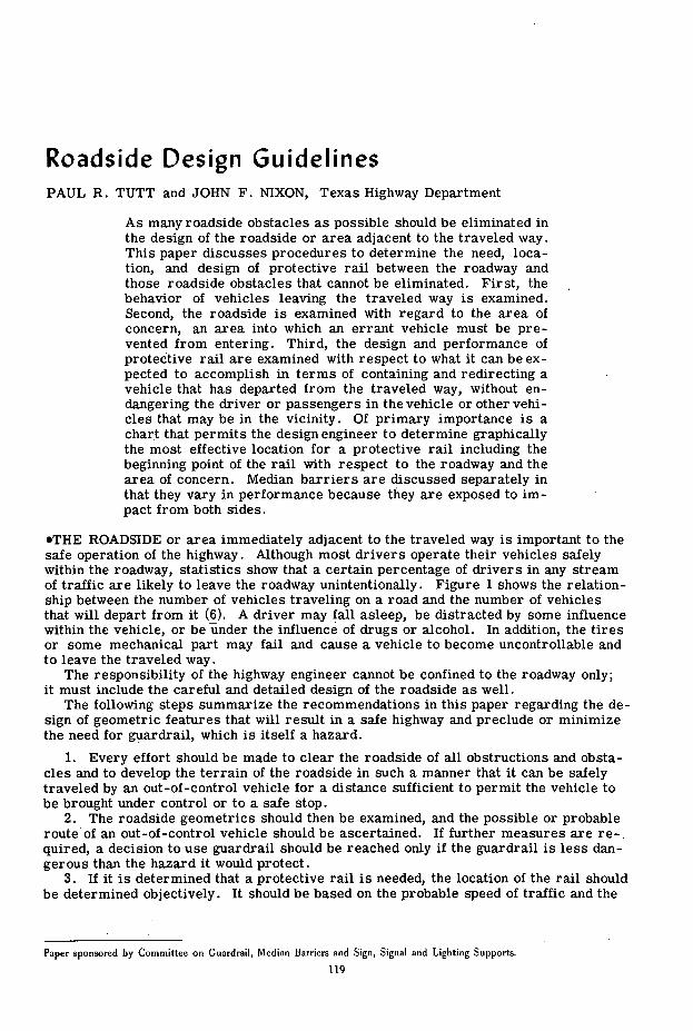
Figure 3. Longitudinal distances traveled by vehicles leaving the roadway.
vehicles leaving the traveled way provide some information, and additional data have been acquired by observing tracks left on the roadside during wet weather.
The longitudinal distance or distance parallel to the roadway traveled by a vehicle moving down the roadside is of primary concern in determining what roadside conditions need attention. The angle at which the vehicle departs from the pavement, although it is not likely to remain constant, is also of interest. The lateral distance traveled and the speed and performance characteristics of the vehicle also play an important part in determining what parts of the roadside are critical.
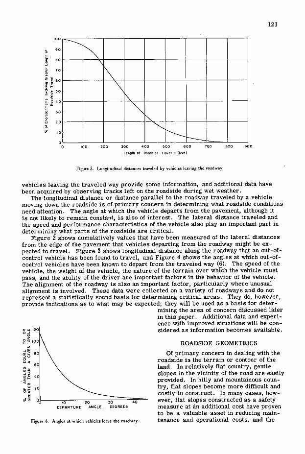
Figure 2 shows cumulatively values that have been measured of the lateral distances from the edge of the pavement that vehicles departing from the roadway might be ex-pected to travel. Figure 3 shows longitudinal distance along the roadway that an out-of-control vehicle has been found to travel, and Figure 4 shows the angles at which out-of-control vehicles have been known to depart from the traveled way (6). The speed of the vehicle, the weight of the vehicle, the nature of the terrain over which the vehicle must pass, and the ability of the driver are important factors in the behavior of the vehicle. The alignment of the roadway is also an important factor, particularly where unusual alignment is involved. These data were collected on a variety of roadways and do not represent a statistically sound basis for determining critical areas. They do, however, provide indications as to what may be expected; they will be used as a basis for deter-
mining the area of concern discussed later in this paper. Additional data and experi- ence with improved situations will be con-
1 201 sidered as information becomes available.
2 .-J uJ -
0 5J4
wz
IL 04
50
Figure 4. Angles at which vehicles leave the roadway
ROADSIDE GEOMETRICS
Of primary concern in dealing with the roadside is the terrain or contour of the land. In relatively flat country, gentle slopes in the vicinity of the road are easily provided. In hilly and mountainous coun-try, flat slopes become more difficult and costly to construct. In many cases, how-ever, flat slopes constructed as a safety measure at an additional cost have proven to be a valuable asset in reducing main-tenance and operational costs, and the

122
7LIt\\ q ' .rq
-"
Figure 5. Roadgide slopes and culverts.
possibility of earth slides is greatly di-minished. Also, construction operations are accomplished in a safer manner and with less difficulty.
Varying slopes that take advantage of all of the area available are more desir-able than those that are designed according to a fixed-slope ratio. The warped slope shown in Figure 5a presents a pleasing view to the motorist and could be traveled in relative safety. Abrupt changes in slope (Fig. 5b) should be avoided. This results not only in a more pleasing roadway but also in reduced costs for grading because the necessity to be exact is not as great as it is where earthwork is shaped to pre-cise dimensions. It is also necessary to design appurtenances adjacent to the road-way in such a way that they blend into the slope. Culvert ends are frequently treated as shown in Figure 5c, whereas treatments such as shown in Figures 5d and 5e would serve as well without pre-senting a hazard.
The modification of existing structures to conform to these shapes will require ingenuity, but this is usually preferable to installing a rail. Broad shallow channels provide better vegetation possibilities and also result in less erosion and fewer drain-age problems. Mowing and other mainte-nance functions are also less costly and safer.
Roadside sign and illumination poles (Fig. 6) and other roadside installations can be fitted with slip-joint or frangible bases to eliminate the possibility of a se-rious collision. Frangible mounts, how-ever, may not be feasible for mast-arm poles because of the danger that the poles may fall onto the road. If these poles can-not be shielded with guardrail, they should be eliminated and the signal heads sus-pended from a cable wire supported by poles located farther from the roadway. Every effort should be made to reduce the number of poles adjacent to roadways in urban areas. Frequently, poles can be used jointly by several agencies. Obstruc-tions can generally be eliminated on new projects, and many can also be eliminated on existing facilities. Only when no better treatment is available should a protective rail be considered.
AREA OF CONCERN
When all possible means have been used to free the roadside of obstacles and to

123
l'igurt. 6. Roadside sign and iltuniination pole..
reduce all slopes as much as possible, certain areas will likely remain that will con-stitute a hazard to moving traffic, particularly along existing roadways that are being modernized. Even on new construction, some hazards may remain. These hazardous areas, referred to as areas of concern, may take various shapes such as a bridge column covering only a few square feet or a drainage ditch covering many square feet and extending from the vicinity of the roadway to the right-of-way line. Because all other means of eliminating these hazards have been exhausted, it must be assumed that a protective rail will be required to prevent errant vehicles from entering or reaching the area of concern.
The boundaries of the areas of concern are determined by the behavior of the out-of-control vehicle and the geometry of the roadside, i.e., whether the roadside area is safe for travel and where the errant vehicle is apt to go after leaving the roadway. Cer-tain types of obstructions are obvious hazards in that they present a positive barrier to the movement of traffic. Other features, such as slopes, must be viewed in the light of past experience and research results to determine the degree of hazard.
Several types of areas of concern are shown in Figure 7. An abrupt ditch or cut at right angles to the traveled way and extending across the right-of-way is unquestionably
;Aroaof ( onc.rn - Tr..
Area of Conc.rn
oge tch
IS -- %
Figure 7. Examples of areas of concern.
!. 1. a,. ... .. :u
21
41
SI
id
Figure 9. Flex-beam guardrail.
124
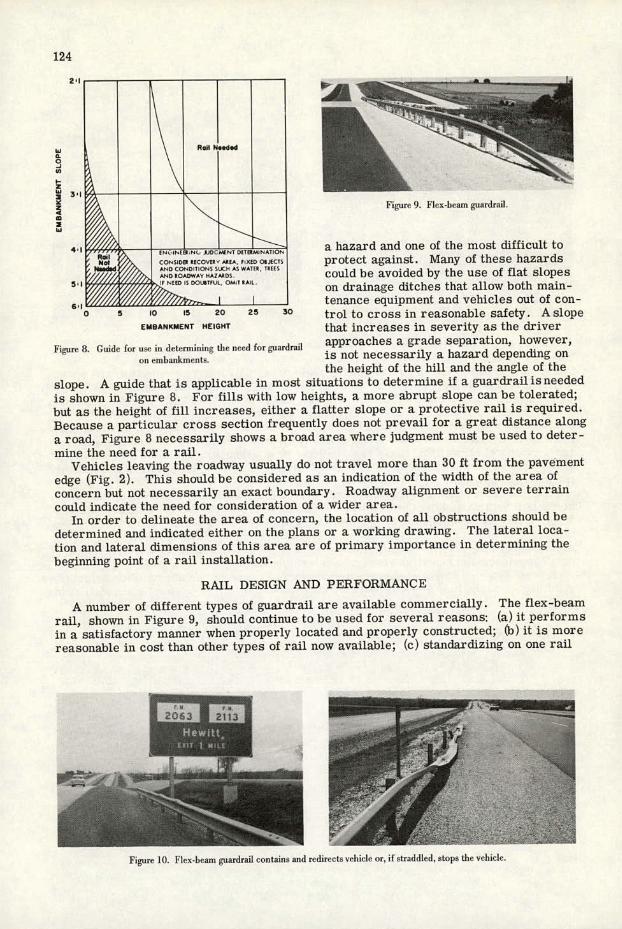
a hazard and one of the most difficult to protect against. Many of these hazards
_________________
could be avoided by the use of flat slopes on drainage ditches that allow both main-
_________________________ tenance equipment and vehicles out of con- 0 5 10 15 20 25 30 trol to cross in reasonable safety. A slope
EM8ANKNENT HEIGHT that increases in severity as the driver
Figure 8. Guide for use in detrrmininc the need for guardrail approaches a grade separation, however,
on einluunkrnents. is not necessarily a hazard depending on the height of the hill and the angle of the
slope. A guide that is applicable in most situations to determine if a guardrail is needed is shown in Figure 8. For fills with low heights, a more abrupt slope can be tolerated; but as the height of fill increases, either a flatter slope or a protective rail is required. Because a particular cross section frequently does not prevail for a great distance along a road, Figure 8 necessarily shows a broad area where judgment must be used to deter-mine the need for a rail.
Vehicles leaving the roadway usually do not travel more than 30 ft from the pavement edge (Fig. 2). This should be considered as an indication of the width of the area of concern but not necessarily an exact boundary. Roadway alignment or severe terrain could indicate the need for consideration of a wider area.
In order to delineate the area of concern, the location of all obstructions should be determined and indicated either on the plans or a working drawing. The lateral loca-tion and lateral dimensions of this area are of primary importance in determining the beginning point of a rail installation.
RAIL DESIGN AND PERFORMANCE
A number of different types of guardrail are available commercially. The flex-beam rail, shown in Figure 9, should continue to be used for several reasons: (a) it performs in a satisfactory manner when properly located and properly constructed; (b) it is more reasonable in cost than other types of rail now available; (c) standardizing on one rail
Figure 10. Flex-beam guardrail contains and redirects vehicle or, if straddled, stops the vehicle.

125
type reduces both construction and main- tenance costs; and (d) it is available from
0" a number of sources - Flex-beam rail functions in two dis-
tinct ways (Fig. 10). The vehicle impact-ing the side of the rail usually will be con-tained and redirected with some damage
-4 to the vehicle and some damage to the rail. A vehicle hitting the end of the rail will straddle the rail and crush it to the ground, and the decelerating action of the posts will bring the vehicle to a stop with consider-able damage to the rail and the underside
Figure Ii. Skid ,iiark iiideate that ciirh eaued chick to hit of the vehicle but with no injury to the top of rail and roll down embankment, driver and passengers. A minimum length
of 150 ft of rail is needed in advance of a stiffer bridge rail and in advance of an ob-
struction that is behind the rail but nearer than 6 ft to it. Otherwise, a vehicle that has straddled the rail may hit the obstruction before being brought to a halt.
Several other conditions are necessary to the proper performance of a protective rail. Although the rail does have a cross section that would resist some bending mo-ment, it is primarily a tension member because the section will often be crushed when the rail is hit. For this reason, it must be securely anchored at both ends. The strength of the rail is adequate for vehicles of average size but only marginally adequate for heavy trucks, particularly at extreme angles. Every effort should be made, therefore, to position the rail properly to take full advantage of all the strength characteristics it possesses.
A rail installation should preferably be located on level ground with no curbs or slopes nearby, as any irregularity that might impart a vertical force to an out-of-control vehicle is likely to detract from the performance of the rail. When curbs are neces-sary to protect fill slopes from erosion, they should be placed behind the face of the guardrail. Figure 11 shows the skid marks of an out-of-control vehicle that was on the ground until striking a 3-in, curb. From this point on, the vehicle left no skid marks; it hit the rail near the top and rolled over it and down the embankment.
Other obstructions and slopes in the vicinity of the rail can also have an adverse ef-fect on the performance of the rail. A steep slope immediately behind the rail (Fig. 12) might permit a straddling vehicle to roll down the slope even though it had been stopped by the rail.
In most cases, particularly on new construction, the location of the rail will be par-allel to the roadway and a constant distance from the roadway shoulder. In existing situations, however, it may be necessary to provide a transition from one rail position to another. These transition lengths should be based on a flat smooth curvature of no morethan2deg maximum as shownin Figure 13. Greater curvature increases the possi-ble impact angle and the possibility of unsatisfactory performance. Figure 14 shows a well-designed installation that should perform in a satisfactory manner. The means
r.
- p.
Figure 12. Steep slope behind guardrail.

Roil
x V x V 108
2 150 5 240
3 85 6 260
4 214 7 280 8 300
Figure 13. (iiardrail transition length based on 2 deg reverse curse.
for arriving at the length, location, and position of this rail, however, are dependent on the factors discussed earlier in this report.
RAIL LOCATION
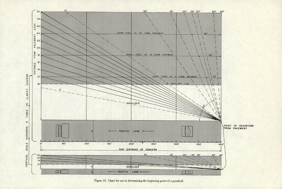
A protective rail must be located so that it will prevent a vehicle from entering an area of concern. Data strongly indicate that the area within 30 ft of the traveled way is critical and that greater distances, depending on vertical and horizontal alignment, may be considered. The distance along the roadway that an out-of-control vehicle can be expected to travel is even less predictable, but the data shown in Figure 3 indicate a travel distance along the roadway of 400 ft after the vehicle leaves the pavement. This figure is somewhat arbitrary, and the designer may wish to consider a greater distance in some instances. Establishing a figure is necessary, however, in order to develop a procedure for determining the beginning point for a protective rail system.
Rail Location Chart The chart shown in Figure 15 has been developed to assist in the proper positioning
of a rail element with respect to an area of concern. It is based on the criteria pre-viously discussed and makes it possible to apply these in an orderly manner and to in-clude only controlling factors. The lower portion of this chart is a scale drawing of a portion of highway 400 ft in length and extending 30 ft laterally from the edge of the traveled lane; these dimensions were determined as described earlier. The upper por-tion of the chart represents the same length of road but is drawn with the lateral scale at right angles to the traveled way expanded to 8 times that of the longitudinal scale; the lateral and longitudinal scales are normal, but the angle measurements are dis-torted as indicated. This expansion makes it possible to take measurements directly
from the chart. The lengths derived from the chart are
the lengths of rail necessary at the approach ____________ - to an area of concern. In addition rail ----- = will be required immediately adjacent to
the area of concern, and an anchor see-
- -. tion 25 ft in length, as shown in Figure 14,
will be required at the approach end and also at the departure end unless the depar-ture end becomes an approach end from the opposite direction or is anchored in some other manner.
To use this chart requires that the lat- Figure 14. laiiple .f a oll-dsigned guardrail ir,stall.ition. eral dimensions of the area of concern be
126
30 - ____________ N
_____________________ IU' 5° 20° 25° 30° 60
A CE-AT 24 FROM PAVEMENT \\
22* 'T N
0 is, 8 FROM PLI(M(NT \ \ 50'
Ln
,,_____ - - - - - - - - - PU R_Ll!L_\__\
\\\\\\\
sHorLDE .I I L L 1
TRAFFIC LANE
L• I 0' 50 100' 50 200 250 300' 350 40 40PISTANCL
MER
SN -
— TRAFFIC LANE - I T151
Figure 15. Chart for use in determining LIII' beginning point of a guardrail.
POINT OF DEPARTURE FROM PAVEMENT
128
30 Edo. of Area of Concern
- .. tI
concernA —
! JXF
- - 7 ,25 anchor
POInt of Deporlore Fran. Partrentint
ShOolder
I - I --- Tronel Lone I I
00 200 240 300 400
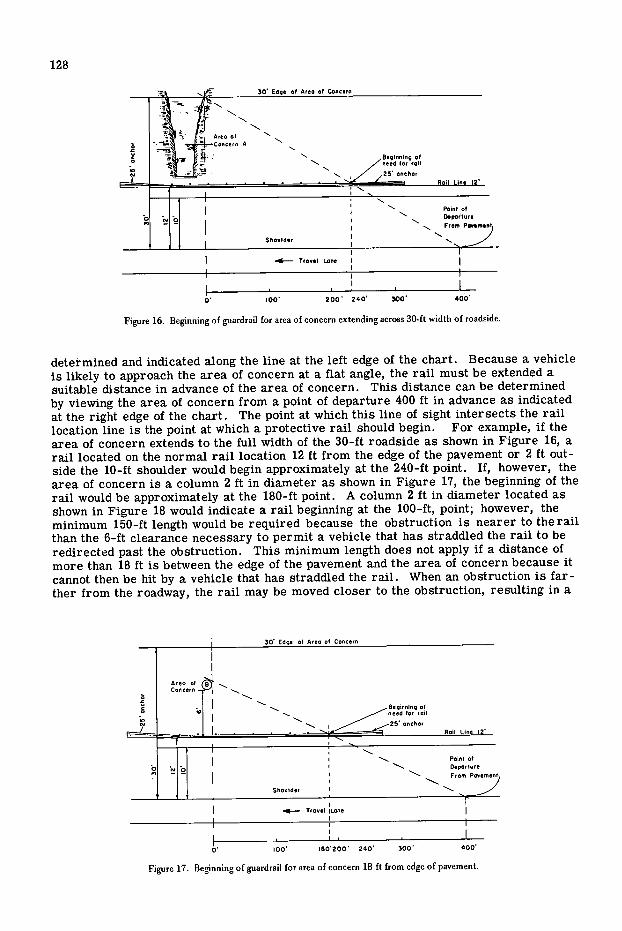
Figure 16. Beginning of guardrail for area of concern extending across 30-ft width of roadside.
determined and indicated along the line at the left edge of the chart. Because a vehicle is likely to approach the area of concern at a flat angle, the rail must be extended a suitable distance in advance of the area of concern. This distance can be determined by viewing the area of concern from a point of departure 400 ft in advance as indicated at the right edge of the chart. The point at which this line of sight intersects the rail location line is the point at which a protective rail should begin. For example, if the area of concern extends to the full width of the 30-ft roadside as shown in Figure 16, a rail located on the normal rail location 12 ft from the edge of the pavement or 2 ft out-side the 10-ft shoulder would begin approximately at the 240-ft point. If, however, the area of concern is a column 2 ft in diameter as shown in Figure 17, the beginning of the rail would be approximately at the 180-ft point. A column 2 ft in diameter located as shown in Figure 18 would indicate a rail beginning at the 100-ft, point; however, the minimum 150-ft length would be required because the obstruction is nearer to the rail than the 6-ft clearance necessary to permit a vehicle that has straddled the rail to be redirected past the obstruction. This minimum length does not apply if a distance of more than 18 ft is between the edge of the pavement and the area of concern because it cannot then be hit by a vehicle that has straddled the rail. When an obstruction is far-ther from the roadway, the rail may be moved closer to the obstruction, resulting in a
I .-.-- Trowel jL0.0 I
01 too' 80200 240 300 400
Figure 17. Beginning of guardrail for area of concern 18 ft from edge of pavement.
30' Edge at Area of Concern
Area of 100' + Concern Beginning of ,.
roil
Point of
From Poemem
-
Sho.Ider '-
-mit- 1,00.1 Lone I
0' 100' 200 300' 400
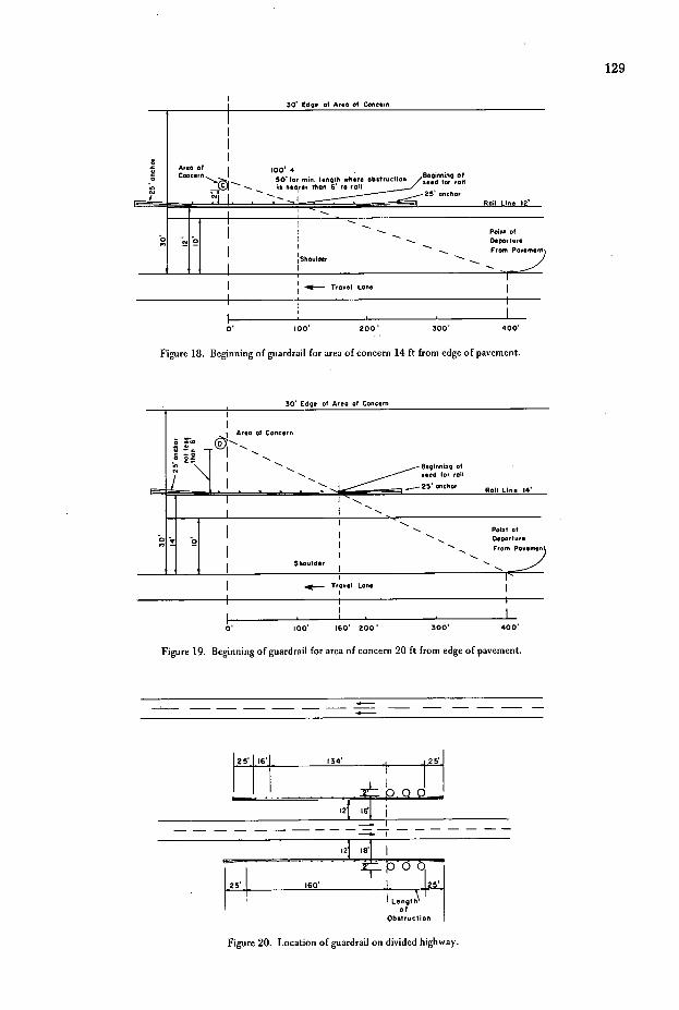
Figure 18. Beginning of guardrail for area of concern 14 ft from edge of pavement.
30' Edge at Area of Concern
Alec, of
!
Concern
Beginning of
I . Point of 3 q
I _.. Departor. - I From Poe
Shooldsr
Trooel LOne I
0' 100' 160' 200 300' 400
Figure 19. Beginning of guardrail for area of concern 20 ft from edge of pavement.
25 16 134' I
- .QJ I2'j j
I2jII
25' 160' I Lengtl
of Obstroction
Figure 20. Location of guardrail on divided highway.
129

A-
130
ArIa otConc.,n
- 24P 240
— BRIDGE
- 240 240 Anchm
-
I'igurc 21. I,oeIion of guardrail on 2-lane highway
shorter approach section (Fig. 19). It should not be closer than 6 ft to the obstruction, however, and this arrangement should be used only if the entire rail length can be placed 14 ft from the pavement and if it does not require a rail transition.
Divided Highways
On 1-way roads, obstructions on both the right and left are dealt with in a similar manner. The rail can be terminated at a point adjacent to the termination of the area of concern (Fig. 20).
Undivided Highways
On 2-lane 2-direction roads, approaches from both directions should be treated in the same manner (Fig. 21) because statistics show that vehicles departing from a 2-lane roadway are as likely to go to the left as to the right. The alignment of the roadway is also a factor in the location of protective rail. The chart shown in Figure 15 was de-veloped for a tangent section by using data taken from sections of roadway having vary-ing but generally good alignment. It is possible to adapt the chart to varying alignments with some degree of confidence, particularly on higher type roads.
Bridge Rail Approaches
One of the most prevalent uses of protective rail is in connection with structures. Columns have been discussed earlier. A protective rail on the approach to a structure and the rail on the structure itself should be completely compatible, with alignment of the rails matching and giving little indication to the motorist that he is crossing a struc-ture (Fig. 22). The length of rail required will depend on the width of the area of con-cern.
Figure 22. Alignment of guardrail on bridge and on approach to bridge.

131
Figure 23. Guardrail transition at jiarrow bridge. Figure 24. I I.'-1,zrn riaili guardrail dliii (Ire ii to another
iypr of bridge rail.
If the structure is narrower than the crown of the road, a rail transition is re-
"a. quired (Fig. 23); the beginning point is
— determined from the chart in Figure lSas though a transition were not necessary.
If the bridge rail is not a flex-beam rail, the approach flex-beam rail should
1 be anchored to the bridge rail with a con- nector that develops the full strenh of
Figure 25. Approach guardrail extended across bridge in front the rail (Fig. 24). In some cases it may
of bridge rail, be feasible to extend the approach rail across the bridge in front of the existing bridge rail and thus eliminate the need
for an anchor (Fig. 25). Because of the many types of existing rail, many variations of this treatment will be needed. In each case, however, the top of the rail should be 27 in. above the traveled way and the face of the flex-beam should be flush with or in front of the face of the curb.
MEDIAN BARRIERS
Because the median is exposed to traffic on both sides, it requires special considera-tion in the design and location of a guardrail barrier. In most cases, a median 48 ft wide or less will require a continuous median barrier at some stage in the design life of the facility, and this should be kept in mind at the time the freeway is designed. On new urban-area construction a continuous median barrier is common in medians 24 ft wide. The same general rules that apply to other areas also apply to the median, but the double exposure factor plus the other factors involved result in a continuous rail being the most practical solution in most cases.
The 24-ft median with a continuous rail barrier, shown in Figure 26 (left), is satis-factory in most cases. However, the rail should be free of obstructions including curbs
Figure 26. Median harriers

132
and solid obstructions within the barrier. Recent developments in freeway lighting
- have resulted in the placing of illumination standards in the median, and, where this
-.' is the case, a completely nonyielding bar-ncr, such as that shown in Figure 26 (right)
- . may be preferable. - 4 . Except where additional lanes in the median are planned, median widths between the 24-ft minimum and the 60-ft width that provides minimum clearances for out-of-
Figure 27. Freeway that iuhl he modified Iii extending control vehicles are impractical. Freeway median a io- bridge,
medians 24 ft wide and less will, in most cases, initially require the installation of
a median rail barrier. If illumination standards are contemplated, the barrier should probably be of the type shown in Figure 26 (right). In all cases, the median barrier should be continuous across structures with no change in the design of the barrier and no obstructions of a nonyielding type within the median barrier except where the non-yielding concrete parapet is provided.
Where older freeways are being modified, it would be desirable to eliminate median curbs and to extend the median across the structure. Figure 27 shows a freeway that could be modified in this manner.
The beginning or termination point of a median barrier will normally fall at a place where there is a transition into a wider or narrower section. When this occurs, the approach rail should extend well into the approach roadway; the beginning point is determined by the guidelines set forth earlier. The termination of the rail where traf-fic is departing from the continuous rail section should be at a point where the road-ways have departed sufficiently so that a median barrier is no longer required.
REFERENCES
Highway Guardrail —Deter mination of Need and Geometric Requirements With Par-ticular Reference to Beam-Type Guardrail. HRB Spec. Rep. 81, 1964.
Cickowski, W. G., Skeels, P. C., and Hawkins, W. R. Appraisal of Guardrail Installations by Car Impact and Laboratory Tests. HRB Proc. 40, 1961, pp. 137- 178.
Beaton, J. L., and Field, R. N. Dynamic Full-Scale Tests of Median Barriers. HRB Bull. 266, 1960, pp. 78-125.
Development of an Analytical Approach to Highway Barrier Design and Evaluation. New York State Department of Public Works, Albany, Research Rept. 63-2, May 1963.
Hutchinson, J. W., and Kennedy, T. W. Medians of Divided Highways—Frequency and Nature of Encroachments. Eng. Exp. Station, Univ. of Illinois, Urbana, Bull. 487, 1966.
Hutchinson, J. W. The Significance and Nature of Vehicle Encroachments on Medians of Divided Highways. Dept. of Civil Engineering, Univ. of Illinois, Urbana, Highway Eng. Series 8, Dec. 1962.