robot multiple contact control - stanford ai...
TRANSCRIPT
Robotica (2008) volume 26, pp. 667–677. © 2008 Cambridge University Pressdoi:10.1017/S0263574708004281 Printed in the United Kingdom
Robot multiple contact controlJaeheung Park∗† and Oussama Khatib‡
†Stanford Artificial Intelligence Laboratory. Address: Gates Building Room 122, 353 Serra Mall #146, Stanford,CA 94305-9010.‡Stanford Artificial Intelligence Laboratory. Gates Building Room 144, 353 Serra Mall #146, Stanford, CA 94305-9010.
(Received in Final Form: February 7, 2008. First published online: March 27, 2008)
SUMMARYThis paper addresses the problem of contact force control formultiple contacts distributed over multiple links in a robot.This is of importance when performing complex tasks inunstructured environment, particularly in humanoid robotapplications. The proposed multicontact control frameworkprovides a new way of defining the operational spacecoordinates, which facilitates the specification of multiplecontact control. The contact force space on multiple linksis constructed as an operational space for the highestpriority task. Motion control, given lower priority, canbe executed using the rest of degree of freedom withinthe null-space of the force control. The dynamic controlstructure, then, provides a means to control each contactforce and motion independently. This dynamic decouplingenables each contact force controller to utilize linear controltheories. In particular, the contact force controllers adopt fullstate feedback control and estimation methods to producerobust performance with respect to modeling and parameteruncertainties. The effectiveness of the multiple contactcontrol framework was demonstrated using a PUMA560manipulator, with multiple contacts on the end-effector andthird link. The demonstrated tasks involved controlling eachof the contact forces with null-space motion.
KEYWORDS: Multiple contacts; Multiple links; Forcecontrol; Motion control; Humanoid; Manipulator.
1. IntroductionRecent developments in humanoid robotics have ignited anexpectation for these robots to begin operating in humanenvironments. While many mechanically sophisticatedhumanoids have been designed, there still exists thechallenge of providing these robots with appropriatecontrol frameworks to cope with complex and unstructuredenvironments. These environments differ greatly fromtraditional settings such as factory floors and assembly lines.In addition to the increasing complexity of the intendedoperating environment, the robots themselves have evolvedinto more complex and highly articulated systems.
Tasks for high DOF robots in complex environments ofteninvolve multiple contacts over multiple links (Fig. 1). Thesetasks require precise and robust control of contact forces as
*Corresponding author. E-mail: [email protected]
well as motion for the entire robot. Most control algorithms,however, have been developed for the execution of tasks onlyat the end-effector. This paper proposes a new approach onhow to specify and execute tasks in the case of multiplecontact over multiple links with the environment.
Most of the research in motion and force control strategyhas dealt with contact at the end-effector of the manipulator,since the manipulators were specifically designed to onlyinteract with the environment at the tip.5,26,29 Compliantframe selection matrices were introduced in ref. [22] to selectcompliant directions to interact with the environment, andlater Khatib [11] presented generalized selection matrices todescribe the decomposition of the end-effector space in thecontact frame. These selection matrices, however, are limitedto orthogonal decomposition at the control point of the end-effector. In general, the contact force space and motion spaceof the end-effector may not be orthogonal to each other. Thisproblem has been discussed by refs. [3, 8, 14, 18, 28], wheremore general kinematic contact models have been proposed.However, these contributions are still specifically focused oncontacts at the end-effector.
While substantial research has addressed contact at theend-effector, much less research has addressed the control ofmultiple contacts on multiple links. Liu et al. [15] present anadaptive control approach for multiple geometric constraintsusing joint-space orthogonalization. Using the geometricconstraints, the joint velocity commands are composed forcontact force and motion control, separately. However, thisapproach does not provide a decoupled control structure foreach contact, and does not allow to consider different modelsof the contact environment. A unified task specificationapproach is presented based on constraints in ref. [25].Interaction forces are introduced as dynamic constraints anddifferent control approaches are presented. Among them,torque based control is explained but it does not deal with theissue of coupling effect among interaction forces themselvesand motion control.
On the other hand, robots having multiple contacts havebeen investigated in the field of grasping and whole armmanipulation.2,16,24,30 Multiple branches of the robot, suchas fingers, make contacts with an object to manipulate orsupport the object. Also other parts of the links, such aspalm, contribute to it. The focus of the research has been thecontrol issue of the handled object and kinematics to generaterequired contact forces.

668 Robot multiple contact control
Fig. 1. Humanoid robot experiencing multiple contacts with acomplex human environment.
In this paper, we present a task specification approachand control framework for multiple contacts over multiplelinks. It is based on our earlier work19 and experimental datapresented in refs. [18,19]. Our attention is more on the controlissue of a robot than an object, which mainly differs fromthe work on grasping: how to provide a control structurenot only for contact force but also for motion tasks of therobot. In a general case, the contact environment can alsobe multiple objects. Our proposed approach employs a newway of defining operational space with contact normals at allcontacts over the links.
The hybrid motion/force control divides the end-effectorcontrol into motion and force control using selectionmatrices.11 This approach cannot be directly generalized tothe case of contacts at multiple links. The composition of theoperational space coordinates for all the contact links andthe associated selection matrices cannot provide a controlstructure for either contact force or motion because theresulting operational space for both contact force and motionwould easily result in having larger degree of freedom thanthe robot as a whole robot. The new approach proposed inthis paper is to give a higher priority to contact force controlsince this is the most critical aspect during interaction withthe environment. An efficient way of specifying this contactforce control is to construct each operational space coordinateas the normal force direction of the corresponding contactpoint, forming the minimal operational space coordinates.The motion control is then composed in the null-space of thecontact force control. This approach provides an effectivemethod of task specification as well as a control frameworkto deal with multiple contacts.
The dynamics of the operational space coordinates arethen obtained by projecting the robot dynamics into thecorresponding space. Additionally, an environment modelis specified to obtain the dynamics of contact forces. Controltorques are chosen to compensate for the dynamics, resultingin a linearized second-order system for each contact force.9,11
This framework allows the use of any linear controller atthe level of the decoupled system. The nonlinear dynamicdecoupling method for robots is effective since inaccuraciesof the model used for decoupling have only a minor effectcompared to the unknown disturbances, unmodeled friction,and parameter errors in the environment model, which arealready being dealt with by the linear controller.
Among linear control theories, the active observer design(AOB)6 is chosen to improve the robustness with respectto disturbances. The AOB design uses a Kalman observerand full state feedback with input disturbance estimation;10
thus, it realizes a model reference control approach,1 whichimplements controllers to adaptively follow the desiredmodel of the system response rather than simply trackinga reference trajectory.
The main contribution of this paper is the development ofa new approach in the composition of the control variables(the operational space coordinates), which provides a controlstructure in the multi-contact situation. This was not possiblein previous hybrid motion/force control methods.8,11,23 Then,full state feedback control with Kalman observer (AOB) wasimplemented at the level of linearized systems. The overallcontrol structure exploits the dynamic model of the system;thus, it enables us to use the Kalman estimator at the level ofeach linearized system, which corresponds to each contactforce.
This new approach has been developed for applicationin high DOF robots, such as humanoids making contactsat multiple links (Fig. 1). Due to hardware limitations,experiments were conducted on a PUMA560 manipulatorto demonstrate the performance of the multi-contactforce control approach. To our knowledge, it is the firstdemonstration of a multiple contact control framework overmultiple links on a physical robotic system. Multiple contactcontrol on one link and multiple links was demonstratedto show the effectiveness of the multiple contact forcecontrol framework. During the multi-contact demonstration,the contact points were moving, i.e., sliding, on the surfacesince the motion was also controlled in the null-space of thecontact force control.
2. Control Framework for Multicontact Force ControlThe hybrid motion/force control of the end-effector uses aselection matrix, which selects the force and motion controldirections in an orthogonal frame.11,22 In Fig. 2(a), a robotis in contact with a horizontal plane. Therefore, the verticaldirection can be chosen as a force control direction and theothers as motion control directions using a selection matrix.It has been further generalized so that arbitrary force andmotion at the end-effector (Fig. 2(b)) can be composed.8 Indealing with multiple contacts, the corresponding multiplelinks can be chosen to concatenate the 6 dimensionaloperational coordinates of the each link23 while a selection

Robot multiple contact control 669
Fig. 2. (a) Motion and force control direction of the end-effector in contact with a horizontal plane. A selection matrix can be determinedto select the force and motion control directions. (b) End-effector in multiple contacts with the environment, where motion and force spaceare not orthogonal.
matrix can be used for force and motion control at eachlink. This approach, however, may result in operational spacecoordinates which are larger than the degrees freedom of therobot. For example, two link contact situation would require12 dimensional coordinates. Among them, force and motioncontrol would be decided by selection matrices. The motionor force control cannot be both controlled appropriately ifthe robot has less than 12 degrees of freedom.
In most interactions with the environment, contact forcecontrol has higher priority since it is closely related to thesafety of the robot, environment, and human. A new approachis proposed based on this priority. The goal is to constructthe operational space using the contact force space such thatthe contact force control can be achieved within the degreesof freedom of the manipulator. This is the main contributionof the paper; unlike previous approaches it can be expandedto multiple contacts, with the remaining degrees of freedomof the robot utilized for motion control.
2.1. Operational space coordinates using contact normalsGiven the contact position and configuration of a link, thecorresponding Jacobian and contact normal vector can bedefined. In the case of point contact as illustrated in Fig. 3, theJacobian corresponds to the point of contact and the contactnormal vector is a unit vector normal to the contact surface.The Jacobian and contact normal vector for the ith contactare denoted as J i and ni
c. The Jacobian of the operationalspace coordinate is defined as
J ic = ni
c
TJ i. (1)
The instantaneous velocity of the coordinate is denoted as ϑic
later in the paper.For m contacts over multiple links, the Jacobian for the
operational space coordinates is obtained by concatenating
Fig. 3. Multi-contact on a link. n1c and n2
c are unit vectors normal tothe contact surfaces, respectively.
these Jacobians for each contact.
Jc =
⎛⎜⎜⎜⎜⎝
J 1c
J 2c
...
Jmc
⎞⎟⎟⎟⎟⎠
. (2)
Similarly, a concatenation of ϑic vectors forms the
instantaneous velocity of the operational space coordinate,ϑc, and a concatenation of f i
c forms contact force vector, fc.A unit vector, ni
c, can be used to describe contact moment.Figure 4 illustrates different kinds of rigid body contactsbetween a robot link and environment. When it is a linecontact (Fig. 4 (b)), one of the ni
c vectors would be theunit vector for the moment about the x-axis, in which therotation of the contact link is constrained. For a plane contact(Fig. 4 (c)), the ni
c vectors would represent the contact normal

670 Robot multiple contact control
Fig. 4. Rigid body contact. (a) Point contact (b) Line contact (c) Plane contact.
force direction, along the z-axis, and moment directionsabout x and y axes.
Generally, the degrees of freedom of contact forces/moments that can be controlled is limited by the numberof joint actuators. The maximum number of contact forcesthat can be controlled by the six DOF PUMA560 robot issix. Consequently, the number of controllable contact forceson a specific link is limited by the degrees of freedom.For example, the maximum number of contacts that can becontrolled at the first link of the PUMA560 robot is onlyone because the link has one degree of freedom. The secondlink, therefore, has two. In addition, the directions of thecontrollable contact force are limited by the kinematics ofthe joints connected to the contact link. These limitations aredue to the kinematic properties of the robot without regardto any specific control framework. The contact forces to becontrolled in this paper are assumed to be chosen within thelimited contact force space. Therefore, the Jacobian, Jc forPUMA560 has less than or equal to six rows.
2.2. Dynamics and control of the robot in contactThe equations of motion for manipulators are of the form
A(q)q + b(q, q) + g(q) + J Tc (q)fc = �, (3)
where q, A(q), b(q, q), g(q), and � are the vector ofjoint angles, the mass/inertia matrix, the Coriolis/centrifugaltorque, the gravity torque in joint space, and the vector ofjoint torques, respectively.
The joint torque vector, �, is chosen to be composed of thetorque for contact force control, and the null space torque:
� = J Tc Fc + NT
c �0, (4)
where the first term J Tc Fc is the control torque for the contact
force control and the second term NTc �0 is the torque in
the null space of the contact force control. The equation ofmotion for ϑc is then obtained by projecting Eq. (3) and (4)into the operational space using J T
c ,
�c(q)ϑc + µc(q, q) + pc(q) + fc = Fc, (5)
where
�−1c (q) = Jc(q)A−1(q)J T
c (q) (6)
J Tc (q) = �c(q)Jc(q)A−1(q) (7)
NTc = I − J T
c J Tc (8)
µc(q, q) = J Tc (q)b(q, q) − �c(q)J (q)q (9)
pc(q) = J Tc (q)g(q). (10)
Equation (5) has the same structure as the dynamicsof the end-effector using the operational space controlframework.11 However, the operational space in this paperdoes not correspond to the dynamics of one link or specificlinks but corresponds to the contact normals over multiplelinks. That is, this equation describes the dynamics of thecontact force/moment space over the entire robot.
The control force, Fc, in Eq. (5) can be designed bycompensating for the dynamic effects with the estimates ofthe matrices, �c(q), µc(q, q), pc(q), and fc.
Fc = �c(q)f ∗c + µc(q, q) + pc(q) + fc. (11)
The resulting equations of motion form the decoupled unitmass system for each contact.
ϑc = f ∗c . (12)
i.e., ϑc,i = f ∗c,i , (13)
where i denotes each contact.Having the decoupled system for each contact, the control
input, f ∗c , for contact force control should be composed using
the relation between the motion and contact force. In practice,it is difficult to identify a precise mathematical model for theactual contact environment. Therefore, there is a trade-offin the modeling of this contact environment. A complicatedmodel could be problematic in terms of the estimation of theparameters and use of the model in the control. In this paper, asimple spring model12 is used for the controller design. In thiscase the environment is assumed to have a constant stiffness.

Robot multiple contact control 671
Fig. 5. A block diagram of the contact force control framework for a manipulator, where the Active Observer (AOB) design is implementedfor force control. The observer in the AOB design includes a state for input disturbance and the estimate of this state will be directlycompensated for in addition to the full state feedback.
Although this model seems too simple to represent the envir-onment, it captures the important characteristic that contactforce on most passive objects increases with deflection.
A higher order model for passive environments is a second-order model with mass, damping, and stiffness. The linearspring model is a special case of this model. When the stiff-ness of the contact object is identified, adding a mass propertyto the model makes the system slower. Therefore, the simplelinear spring model can be considered a conservative modelin terms of stability. The use of a linear spring model on theactual second-order system may decrease the performance.So, the proposed approach is to first utilize the stiffness modeland design a controller, then, compensate for the modelingerrors using an adaptive controller with AOB.
For each contact i, we use the stiffness model
fc,i = ks,iϑc,i , (14)
where fc,i is the ith contact force. The term, ϑc,i , is theinstantaneous velocity in the contact normal direction andks,i is the ith contact environment stiffness.
With this model and Eq. (13), the resulting dynamics foreach contact force, i, are
fc,i = ks,if∗c,i . (15)
The control input, f ∗c,i , can now be computed using any linear
control method. Among them is a full state feedback controlwith estimation of input disturbance, which fits well with theproposed control framework. This controller is explained inSection 3.
2.3. Motion control in the null spaceThe null space control torque, �0, in Eq. (4) is used for motioncontrol. The dynamically consistent null space projectionmatrix, NT
c , projects the torque, �0, into the null space of thecontact forces; thus, the contact forces are not affected by �0.
Having the task-posture decomposition control structurefor the contact force and motion control, the task consistentdynamic equation for motion control can be obtained.13 Thedynamic equation with the control structure is
A(q)q + b(q, q) + g(q) + J Tc (q)fc = J T
c Fc +NTc �0. (16)
We define the operational space coordinate for motion andthe corresponding Jacobian is denoted as Jm.
ϑm = Jmq. (17)
Control torque for motion, �0, is thus chosen as J Tm Fm to
apply control force, Fm, in the null space. Then, the dynamicequation in the motion space is obtained by projecting thejoint space dynamics into the motion space. This projectioncan be performed by pre-multiplying Eq. (16) by J T
m,c(q):
�m,cϑm +µm,c +pm,c + J Tm,cJ
Tc fc = J T
m,cJTc Fc +Fm, (18)
where
�−1m,c(q) = Jm(q)A−1(q)NT
c J Tm (q) (19)
J Tm,c(q) = �m,c(q)Jm(q)A−1(q) (20)
µm,c(q, q) = J Tm,c(q)b(q, q) − �m,c(q)Jm(q)q (21)
pm,c(q) = J Tm,c(q)g(q). (22)
Note that this dynamic equation of motion is consistent withthe task dynamics. That is, the control force Fm is appliedto the null-space of the contact force control. Any torquecomponents that may affect the contact force control will beeliminated by the null-space projection matrix, NT
c .Based upon Eq. (18) and the composed control force, Fc,
for the contact force control, the control force in motioncontrol can be computed as
Fm = �m,cf∗m + µm,c + pm,c + J T
m,cJTc fc − J T
m,cJTc Fc, (23)
resulting in a unit mass system for motion, if the motioncontrol can be executed in the null-space of the force control.
xm = f ∗m. (24)
The total torque to be applied to the robot is
� = J Tc Fc + NT
c J Tm Fm. (25)
The block diagram of the overall control structure is shownin Fig. 5, where the null space control is used for motioncontrol: thus, �0 = J T
m Fm.

672 Robot multiple contact control
2.4. Discussion on control issue of contact force and motionThe rank of the Jacobian, Jc, determines if all the specifiedcontact forces are controllable simultaneously or not. In thecase the rank is deficient, �−1
c in Eq. (6) becomes a singularmatrix. It means not all the contact forces can be controlled.That is, control for some of the contact forces are conflicting.There can be different ways of resolving the situation. Leastimportant contact forces could be eliminated from the taskamong the conflicting contact forces. Or damped pseudoinverse approach can be applied to obtain �c matrix.17,27
This method compromises their performances among theconflicting contact forces. In ref. [4] singular directions areremoved from control near singular configurations and thenull space motion is used for the control along the singulardirections. This is the same issue for the motion control andsimilar approaches could be applied in dealing with �−1
m,c.However, the use of the null-space projection matrix, NT
c ,guarantees force control when the motion control conflictswith it.
3. Contact Force Control with Input DisturbanceEstimationA common approach for contact force control uses aproportional-integral (PI) controller with damping based onthe velocity of the end-effector. One of the main difficultieswith this approach involves hard contact. In this case, the dy-namics of contact with the environment are already very fast,so there is a limitation in the proportional gain that can be em-ployed. Thus, the proportional gain must be kept small, whichin practice results in large steady state error. This error can bereduced by adding integral control; however, this is problem-atic since it may adversely affect the stability of the system.
In addition to this difficulty associated with classicalPI controllers, the stiffness of the environment is difficultto identify and may even change during contact whendeflection occurs. Classical PI controllers cannot deal withthese difficulties since they do not account for uncertaintiesin the system. These facts motivate a force control strategywhich employs an observer that can account for uncertaintiesin a systematic way.
Active Observers (AOB)6 use a modified Kalmanestimator with an additional state, called an active state.The active state is the estimate of the disturbance to theinput of the system. Full state feedback is implemented withestimated states that correspond to the contact force and thederivative of the contact force. In addition, the estimatedinput disturbance (active state) is directly subtracted fromthe input to compensate for the error. This AOB methodis best applied to systems which can be modeled as linearsystems with input disturbance. The linearized contact forcecontrol system is one such system. In this case feedbacklinearization is achieved through the use of the operationalspace formulation. The contact environment is approximatedas a spring model and as such modeling uncertainties needto be considered. In addition to these modeling uncertaintiesmost robots cannot accurately provide the commanded torqueto the system and this mismatch between commanded torqueand actual torque can be treated as an input disturbance. Thedetails for implementation can be found in ref. [7, 20].
4. ExperimentsThe control framework has been developed for a generalrobot, especially one with high DOF and a branchingmechanism, such as a humanoid robot. Due to hardwarelimitations, experimental demonstration was done using aPUMA560 robot. The robot has six degrees of freedom.Therefore, its possible contact and motion tasks were limitedby its kinematics and degrees of freedom.
A PUMA560 manipulator was connected to a PC (runningthe QNX operating system) through a TRC205 amplifierpackage from the Mark V Corporation. This setup allowed auser to program joint torques or motor currents as inputs to therobot. The servo rate of the controller for the PUMA560 robotwas 500 [Hz]. A JR3 force sensor with 6 axis measurementswas mounted on the wrist of the manipulator to measurecontact forces at the end-effector.
The experiments have been conducted to demonstrate theeffectiveness of the control framework and performanceof the contact force and motion control. The first set ofexperiments was for multiple contacts at the end-effector.The multiple contact force control over multiple links wasimplemented in the second set of experiments.
4.1. Multiple contacts at the end-effectorThe system setup, represented in Fig. 6, consisted of a PUMArobot, a table, and a vertical board. The vertical board hada 90◦ angle with the table. As can be seen in Fig. 6, tworigid bars at the end-effector had contacts with the table andthe vertical board. Contact force control was for the normalcontact forces at each contact: one with the table and the otherwith the vertical board. The contact force with the table was inthe z-direction and the one with the vertical board was in they-direction (Fig. 6). Motion control was performed within theremaining four DOF after controlling the two contact forces.The tasks were to maintain the orientation of the end-effector,which was three-DOF task, and to control the wrist point inthe x-direction, one-DOF task. The contact Jacobian, Jc,consists of two rows. The first row corresponds to the normalcontact force with the table. This was obtained by computingthe Jacobian for the contact point and then selecting the rowcorresponding to the z-direction. The second row of Jc wascomputed by the same procedure for the y-direction of the
Fig. 6. System setup for multi-contact at the end-effector. Two hardcontacts are made at the end-effector, one link. Experiments wereconducted for multiple contact control at one link.

Robot multiple contact control 673
Fig. 7. Step responses of force control in case of multiple contacts atend-effector. Sinusoidal input was commanded to the wrist in the xtranslational direction from 190 s. Refer to Fig. 6 for experimentalsetup. (a) Contact force with the table (first contact). (b) Contactforce with the vertical board (second contact). (c) Wrist motion innull-space.
vertical board contact. The corresponding Jacobian, Jm, wasthe concatenation of the Jacobian for the orientation of theend-effector and the selected Jacobian of the wrist point alongthe x-direction in Fig. 6.
Figure 7 shows the experimental result of contact forceand motion control. Square functions were commanded forthe two contact forces. The x direction motion of the end-effector was commanded to track a sinusoidal reference inputwhile the orientation of the wrist was commanded to remainfixed. Since the orientation of the end-effector did not changeduring this motion, the contact point of the end-effectorremained the same throughout the experiments.
Fig. 8. Noise Variance Estimations of the contact forces in case ofmultiple contacts at end-effector. Data is from the same experimentas Fig. 7. (a) Table (first contact). (b) Vertical board (secondcontact).
Figures 7 (a) and (b) show the contact forces over time.The translational motion in the x-direction is represented inFigure 7 (c). The manipulator started with no motion (range[160–190] [s]). In this period, step commands (10 [N] and15 [N]) had been applied simultaneously to both z and y
directions. The operational point of the end-effector (the wristpoint) started moving at 190 [s] in the x-direction.
The contact force reached the commanded force with thedesigned time constant. Figure 8 shows the force variancefor each contact. The variance was about 0.6 [N2] in astatic situation, increasing to about 100 [N2] when themanipulator moved. These changes in force measurementcharacteristics were due to the surface of the environment,along with the fact that the contact point was sliding.When the contact point moved on the surface maintainingcontact, roughness in the surface created larger magnitudeof noise in the measurement. Dealing with these changesin the measurement characteristic, the variance of the forcemeasurement was computed and updated on-line using themost recent 50 samples in the experiments. Without theupdate, instability could easily have occurred when the con-tact points started to slide on the surface. When the noisecharacteristic varied a lot between the static and dynamiccases, the on-line noise characteristic estimation was ableto properly adapt the estimation and control such that thecontact forces were not too badly affected by the motion.

674 Robot multiple contact control
Fig. 9. System setup for multi-link multi-contact. (a) Third link contact. (b) End-effector contact at two points. Motion and force controlexperiments were conducted for the case of multiple contacts over multiple links.
However, the starting motion of the end-effector disturbedboth contact forces significantly due to static friction at about195, 205, and 217 [s].
The value of ks,i = 6, 000 N/m was used for the stiffnessesof both the table and the vertical board. Although this valuewas not accurate, the robust force control with a modifiedKalman estimation (AOB) compensated for modeling errors,guaranteeing the desired contact force dynamics.
4.2. Multiple contacts over multiple linksThe experimental setup for multi-link multi-contact is shownin Fig. 9. Contact force control was for three contacts: oneat the third link, and the others at the end-effector. The firstcontact was established at the third link, and the second andthird contacts were the same as the previous experiments.For the third link contact, the contact force direction wasnormal to the link, i.e., X3 direction in Fig. 9 (a). Therefore,the first row of the contact Jacobian, Jc, was the X3 directionprojection of the Jacobian for the contact point of the thirdlink. The second and third rows of Jc were the same as Jc
from the previous experiments.Motion control was realized within the remaining three
DOF of the robot through null space control. One motiontask was to hold the contact position along the third link,i.e., Z3 in Fig. 9 (a). Additionally, the fourth joint anglewas controlled to track desired motion. The first row ofJm, therefore, corresponded to the motion of the third-linkcontact point in Z3 direction and the second row was simply[0 0 0 1 0 0] for the fourth joint.
To measure the third link contact force, an additionalJR3 force sensor was mounted on the contact environmentsince it is difficult to mount onto the link of the robot. Thecontact normal force can be computed by projecting themeasured contact force to the normal direction of the contactsurface using the kinematics and geometry of the contactlink. The contact point on the link and the correspondingnormal direction to the contact surface changed during themulti-contact experiments with the motion. The change ofthe contact location with respect to the link in the Y3
direction did affect the corresponding contact Jacobian. Thecontact location change, therefore, needed to be accounted
for in updating the contact Jacobian. The contact point withrespect to the link could be estimated using the geometryof the environment and the fact that the environment wasstationary.21 The estimation of the contact point on thelink and the normal direction was updated at each servocycle.
The second and third contacts were at the end-effector;one contact with the horizontal table and the other with thevertical rigid board in Fig. 9 (b). Since the parts on the contacthad a spherical shape, the contact point on the end-effectoralso changed when there was an orientation change at theend-effector. This exact contact location can be estimatedusing the kinematics of the robot and the spherical shape ofthe contacting part. During this experiment, the actual changeof the contact location was within a couple of millimeters.Therefore, this slight change of the contact location was notaccounted for but treated as a modeling error.
The contact environments were a wooden table and awooden vertical board with aluminum frames. Consequently,they were near rigid contacts. However, the mountingbetween the table and the vertical board had some flexibility.The system stiffnesses of the three contacts were set to ks,1 =6, 000 N/m for the third link contact, ks,2 = 6, 000 N/m forthe end-effector contact with the table, and ks,3 = 3, 000 N/mfor the end-effector contact with the vertical board. The actualstiffnesses of all three contacts were effectively infinite athigh contact forces.
Two sets of experiments were conducted with and withoutmotion command in the null space. During the execution ofmotion in the null-space, the contact points were sliding onthe surfaces.
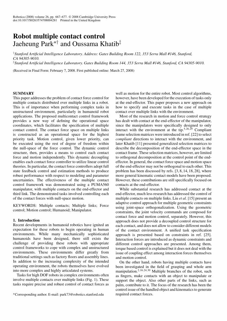
(1) Static contact experiment (Fig. 10): While threecontact forces were controlled, the motion control wascommanded to maintain the starting values. Since all threecontacts were very stiff, the motion of the robot was verysmall during the experiment. When one of the desired contactforces was commanded with square functions, the other de-sired contact forces were controlled to maintain their values.
Although the effect of one contact force control on theothers was not perfectly eliminated, contact force control
Robot multiple contact control 675
Fig. 10. Step responses of force control in case of multiple contactsat multiple links. Refer to Fig. 9 for experimental setup. Threecontact forces were controlled without null-space motion. Squareinputs between −5N and −15N were commanded to each contactand the others were commanded to maintain −5N . That is, a squareinput was commanded to the first contact in (a), to the secondcontact in (b), and to the third contact in (c).
was successfully accomplished. The settling time of the stepresponse was longer than the designed value (0.23 s) mainlydue to the interaction with the other contact force controls.At the time of the step command, the contact force controlcorresponding to the step command created disturbance to theother contact forces, whose controllers, then, compensatedfor the disturbance. The fact that the experimental results donot produce perfect decoupling among the contact forces aredue to mainly two reasons. First, the dynamic model and the
contact location of the robot are not perfect. Second, frictioneffects tangent to the contact surface were not accounted for.This friction is mainly nonlinear static friction or stiction inthis static contact case. Even in a high stiffness environment,the robot force control generates motion and the friction canaffect transient performance.
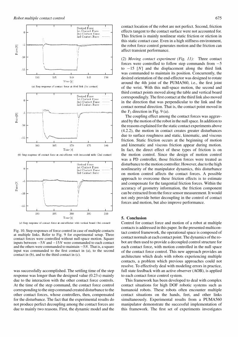
(2) Moving contact experiment (Fig. 11): Three contactforces were controlled to follow step commands from −5to −15 [N] and the displacement along the third linkwas commanded to maintain its position. Concurrently, thedesired orientation of the end-effector was designed to rotatearound the 4th joint of the PUMA560, i.e., the first jointof the wrist. With this null-space motion, the second andthird contact points moved along the table and vertical boardcorrespondingly. The first contact at the third link also movedin the direction that was perpendicular to the link and thecontact normal direction. That is, the contact point moved inthe Y3 direction in Fig. 9 (a).
The coupling effect among the contact forces was aggrav-ated by the motion of the robot in the null space. In addition tothe reasons explained for the static contact experiments above(4.2.2), the motion in contact creates greater disturbancesdue to surface roughness and static, kinematic, and viscousfriction. Static friction occurs at the beginning of motionand kinematic and viscous friction appear during motion.In fact, the direct effect of these types of friction is onthe motion control. Since the design of motion controlwas a PD controller, those friction forces were treated asdisturbance to the motion controller. However, due to the highnonlinearity of the manipulator dynamics, this disturbanceon motion control affects the contact forces. A possibleapproach to overcome these friction effects is to estimateand compensate for the tangential friction forces. Within theaccuracy of geometry information, the friction componentcan be extracted from the force sensor measurement. It wouldnot only provide better decoupling in the control of contactforces and motion, but also improve performance.
5. ConclusionControl for contact force and motion of a robot at multiplecontacts is addressed in this paper. In the presented multicon-tact control framework, the operational space is composed ofcontact normals at each contact point. The dynamics of the ro-bot are then used to provide a decoupled control structure foreach contact force, with motion controlled in the null spaceof the contact force control. This new approach provides anarchitecture which deals with robots experiencing multiplecontacts, a problem which previous approaches could notresolve. To effectively deal with modeling errors in practice,full state feedback with an active observer (AOB), is appliedto each contact force control system.
This framework has been developed to deal with complexcontact situations for high DOF robotic systems such ashumanoid robots. These robots often encounter multiplecontact situations on the hands, feet, and other linkssimultaneously. Experimental results from a PUMA560manipulator demonstrate the successful implementation ofthis framework. The first set of experiments investigates

676 Robot multiple contact control
Fig. 11. Step responses of force control in case of multiple contacts at multiple links. Refer to Fig. 9 for experimental setup. Three contactforces were controlled with null-space motion. Square inputs between −5N and −15N were commanded to each contact and the otherswere commanded to maintain −5N . That is, a square input was commanded to the first contact in (a) and (b), to the second contact in(c) and (d), and to the third contact in (e) and (f). The 4th joint was simultaneously controlled in the null-space, following a sinusoidaltrajectory.
contact with the environment at two points on the end-effector, and the second set of experiments addresses threepoint contact: one at the third link and two at the end-effector. Static and moving contact experiments show thehigh performance of the multi-link multi-contact forcecontrol framework even in the presence of varying contactcharacteristics and disturbance from the motion of themanipulator. Currently, the framework is being implementedand validated on a humanoid system, HONDA ASIMO, inthe Stanford AI laboratory.
References1. H. Ambrose and Z. Qu, “Model Reference Robust Control
for Mimo Systems,” Proceedings of the American ControlConference, Albuquerque, New Mexico (1997) pp. 345–349.
2. A. Bicchi and V. Kumar, “Robotic Grasping and Contact:A Review,” Proceedings of the International Conference
on Robotics and Automation, San Francisco, U.S.A. (2000)pp. 348–353.
3. H. Bruynincks, S. Demey, S. Dutre and J. De Schutter,“Kinematic models for model-based compliant motion in thepresence of uncertainty,” Int. J. Robot. Res. 14(5), 465–482(Oct. 1995).
4. K. Chang and O. Khatib, “Manipulator Control atKinematic Singularities: A Dynamically Consistent Strategy,”Proceedings of the International Conference on IntelligentRobots and Systems, Pittsburgh, U.S.A. (1995) pp. 84–88.
5. S. Chiaverini, B. Siciliano and L. Villani, “A Survey of RobotInteraction Control Schemes with Experimental Comparison,”ASME Trans. Mechatronics 4(3), 273–285 (Sep. 1999).
6. R. Cortesao, Kalman Techniques for Intelligent ControlSystems: Theory and Robotic Experiments. Ph.D. thesis(University of Coimbra, 2002).
7. R. Cortesao, J. Park and O. Khatib, “Real-Time adaptivecontrol for haptic telemanipulation with kalman activeobservers,” IEEE Trans. Robot. 22(5), 987–999, 2006.
8. R. Featherstone, S. S. Thiebaut and O. Khatib, “A GeneralContact Model for Dynamically-Decoupled Force/Motion

Robot multiple contact control 677
Control,” Proceedings of the International Conference onRobots and Automation, Detroit, U.S.A. (1999) pp. 3281–3286.
9. E. Freund, “The structure of decoupled nonlinear systems,” Int.J. Control, 21(3), 443–450 (1975).
10. C. D. Johnson, “Discrete-time disturbance-accommodatingcontrol theroy with applications to missile digital control,”J. Guid. Control 4(2), 116–125 (1980).
11. O. Khatib, “A unified approach for motion and force control ofrobot manipulators: The operational space formulation,” Int. J.Robot. Autom. 3(1), 43–53 (Feb. 1987).
12. O. Khatib and J. Burdick, “Motion and Force Control ofRobot Manipulators,” In: Proceedings of the InternationalConference on Robotics and Automation, San Francisco,U.S.A. (1986) pp. 1381–1386.
13. O. Khatib, L. Sentis, J. Park and J. Warren, “Whole-bodydynamic behavior and control of human-like robots,” Int. J.Humanoid Robot. 1(1), 29–43 (2004).
14. H. Lipkin and J. Duffy, “Hybrid twist and wrench control fora robotic manipulator,” ASME J. Mech. Trans. Autom. Des.110(2), 138–144 (Jun. 1988).
15. Y. Liu, K. Kitagaki, T. Ogasawara and S. Arimoto, “Model-based adaptive hybrid control for manipulators under multiplegeometric constraints,” IEEE Trans. Control Sys. Technol. 7(1),97–109 (Jan. 1999).
16. K. Mirza and D. E. Orin, “Control of Force Distributionfor Power Grasp in the Digits System,” Proceedings of theConference on Decision and Control, Honolulu, Hawaii,U.S.A. (1990) pp. 1960–1965.
17. Y. Nakamura and H. Hanafusa, “Inverse Kinematic Solutionswith Singularity Robustness for Robot Manipulator Control,”ASME J. Dyn. Syst. Meas. Control, 108(3), 163–171 (1986).
18. J. Park, R. Cortesao and O. Khatib, “Multi-Contact CompliantMotion Control for Robotic Manipulators,” Proceedings of theInternational Conference on Robotics and Automation, NewOrleans, U.S.A. (2004) pp. 4789–4794.
19. J. Park and O. Khatib, Mult-link Multi-contact ForceControl for Manipulators. In Proceedings of the InternationalConference on Robotics and Automation, Barcelona, Spain(2005) pp. 3613–3618.
20. Jaeheung Park and Oussama Khatib, “A haptic teleoperationapproach based on contact force control,” Int. J. Robot. Res.25(5–6), 575–591 (2006).
21. A. Petrovskaya, J. Park and O. Khatib, “ProbabilisticEstimation of Whole Manipulator Contacts for Multi-contactControl,” Proceedings of the International Conference onRobotics and Automation, Rome, Italy (2007).
22. M. H. Raibert and J. J. Craig, “Hybrid position/force controlof manipulators,” ASME J. Dyn. Sys. Meas. Control 103(2),126–133 (June 1981).
23. J. Russakow, O. Khatib and S. M. Rock, “Extended OperationalSpace Formulation for Serial-to-parallel Chain(branching)Manipulators,” Proceedings of the International Conferenceon Robotics and Automation, Nagoya, Japan (1995) pp. 1056–1061.
24. K. Salisbury, W. Townsend, B. Eberman and D. DiPietro,“Preliminary Design of a Whole-arm Manipulation System(wams),” In: Proceedings of the International Conference onRobotics and Automation, Philadelphia, PA, U.S.A. (1988)pp. 254–260.
25. J. De Schutter, J. Rutgeerts, E. Aertbelien, F. De Groote, T. DeLaet, T. Lefebvre, W. Verdonck and H. Bruyninckx, “UnifiedConstraint-Based Task Specification for Complex Sensor-Based Robot Systems,” In: Proceedings of the InternationalConference on Robotics and Automation Barcelona, Spain(2005) pp. 3607–3612.
26. B. Siciliano and L. Villani, Robot Force Control, “The KluwerInternational Series In Engineering and Computer Science.”(Kluwer Academic Publishers, 1999).
27. C. W. Wampler, “Manipulator inverse kinematic solutionsbased on vector formulations and damped least-squaresmethods,” IEEE Trans. Sys. Man Cybern. 16(1), 93–101(1986).
28. H. West and H. Asada, A Method for the Design of HybridPosition/Force Controllers for Manipulators Contrainedby Contact with the Environment,” Proceedings of theInternational Conference on Robotics and Automation (1985)pp. 251–259.
29. T. Yoshikawa, “Force Control of Robot Manipulators,”Proceedings of the International Conference on Robotics andAutomation San Francisco, USA (2000) pp. 220–226.
30. Y. Zhang and W. A. Gruver, “Definition and Force Distributionof Power Grasps,” In: Proceedings of the InternationalConference on Robotics and Automation Nagoya, Japan (1995)pp. 1373–1378.