robotic assistants aid surgeons during minimally...
TRANSCRIPT

Robotic Assistants AidSurgeons During MinimallyInvasive ProceduresA Robotic System for Collaboratively or AutonomouslyPerforming Endoscopic Procedures
This article presents the design and imple-mentation of a new robotic system for
assisting surgeons in performing mini-mally invasive surgical procedures. Thissystem is designed for collaborative opera-tion between the surgeon and the robot. Inaddition, it has the following attributes:quick interchangeable end tools, program-mable collaboration with the surgeon, andcoordinated motion of multiple robotic de-vices for performing complex procedures.Two such devices have been built, with avariety of end-tools. The system has dem-onstrated direct manual operation and sur-geon-supervised autonomous stitching andknot tying. In addition to the mechanicaldesign and kinematic analysis, several au-tonomous knot-tying algorithms and theassociated kinematic requirements are dis-cussed. Note that, as the focus here is on therobot design and control, other importantaspects on the clinical deployment of sur-gical robots such as safety, fault detectionand amelioration, man-machine interfacedesign, etc., are not addressed here.
Overview: Robotics’ Role inMinimally Invasive Surgery
Surgery traditionally involves makinglarge incision to access the part of the pa-tient that requires attention. This methodis referred to as the open surgery ap-proach. The incision and the significantdissection needed to allow the surgeon tovisualize the field are the parts of the op-eration that contribute to delayed patientrecovery and cause most of the associ-ated pain.
Minimally invasive surgery (MIS) is acost-effective alternative to open surgery,whereby essentially the same operationsare performed using specialized instru-ments designed to enter into the body
through several tiny punctures, rather thanone large incision. Instead of looking di-rectly at the part of the body being treated,the physician monitors the procedure via aspecial video camera inserted through oneof the small punctures. By eliminating thelarge incision and extensive dissection,much of the pain of recovery can also beeliminated and the length of hospital stayreduced [1].
However, compared to open surgery,MIS is affected by additional physical, vi-sual, motor, spatial, and force constraints.The MIS tools are constrained by the inci-sion point. The surgeon must coordinatethe hand motion that controls the tool,with the remote visual display of the oper-ation being performed by the end-tool.The limited work space and coordinationof a pair of tools further compounds thechallenge.
As a direct result of these constraints,there is an extended learning curve for thesurgeon to gain the required skill and dex-terity. Furthermore, there is a great deal ofoperating variability even among trainedsurgeons. As demonstrated in [2],time-motion studies of endoscopic sur-geries have indicated that for activitiessuch as suturing, knot tying, suture cut-ting, and tissue dissection, the operationtime variation among surgeons can be aslarge as 50%. In suturing, in particular, itwas noted that the major difference lies inthe proficiency at grasping the needle andmoving it to a desired position and orien-tation, without slipping or dropping it.The continuing growth of MIS operationsdepends in a large part on the reduction ofvariability and increase of efficiency ofthe MIS procedures. Toward this goal,many robotic devices have been patentedor proposed in the open literature [3-10].
94 IEEE ENGINEERING IN MEDICINE AND BIOLOGY January/February 20010739-5175/01/$10.00©2001IEEE
©19
99Ar
tville
,and
Digit
alSto
ck19
96
Hyosig Kang and John T. WenCenter for Automation Technologies,
Rensselaer Polytechnic Institute
One class of surgical robotic devicesthat has been proposed to assist in endo-scopic surgeries is based on the concept ofteleoperation. Here, a surgeon performsthe operation remotely, with a robot com-pletely under the surgeon’s command, op-erating on the patient. The robot motion isslaved, via mechanical linkages or com-puter control, to the movement and con-trol by the surgeon [4, 11, 12]. Thesurgeon’s view of the operation may befurther enhanced by remote vision to cre-ate a virtual presence [4, 13-15].
Various robotic positioners and stabi-lizers have also been proposed where,similar to teleoperation, a robot-holdingsurgical tool is controlled so as to followthe surgeon’s command [8, 12, 16, 17].The role of the robot is to filter out tremorsand disturbances of the surgeon’s hands,so as to enhance the precision and me-chanical stability of the operation. Vari-ous specialized robotic tools have alsobeen proposed [18-20]. For example, ad-ditional joints (like fingers) may be addedto the end of the endoscopic tool to en-hance the tool dexterity, without requiringmotion of the entire tool stem. This is par-ticularly useful in cardiac operations,where motion of the tool stem is limited[10, 13, 20].
It is important to note that in the vari-ous robotic surgical assistant systems de-scribed above, the surgical procedures arestill completely performed by the humansurgeon. The human commands are mim-icked by the robotic device through com-puter control. The virtual presence,through visual feedback to the surgeon,creates a sensation that the surgeon is op-erating the tool tip instead of the tool han-dle, thus reducing one of the challenges ofMIS. However, procedures that require ahigh level of skill, such as suturing, liga-tion, and precise tissue dissection, con-tinue to depend on the skill of the surgeon.It is therefore desirable to have a roboticsystem that can collaboratively performendoscopic procedures with the surgeon:performing certain tasks autonomously toreduce the strain on the surgeon, remov-ing variability of surgeons’ training lev-els, and enhancing system efficiency bydecreasing the operation time.
To meet this need, we developed a newsurgical robot design for MIS operations,called the EndoBot, for collaboration be-tween the surgeon and the robotic device.The surgeon can elect either to operatecompletely manually; collaboratively,where some motions of the robotic device
in certain directions are under computercontrol, and other motions are under man-ual control of the surgeon; or autono-mously, where the complete device isunder computer control with the sur-geon’s supervision. Furthermore, the ro-botic tools can be quickly changed from arobotic docking station, allowing differ-ent tools to be used in an operation.
Since surgeons undoubtedly wouldhave different levels of comfort in usingsuch a robotic system, it is imperative thatthe individual surgeon be able to specifythe level of collaboration—from com-plete surgeon direct manual operation tocomplete surgeon supervised autono-mous operation. Such collaborative hu-man/robot control has been proposed inthe context of space telerobotics but hasnot been proposed in the surgical context[21, 22].
MIS operations typically require theuse of a variety of different tools for usessuch as suturing, cutting, dissecting, andgripping. Any protracted tool changewould certainly add to the overall surgicaltime and hence adversely effect the effi-ciency of the operation. For manual MISoperation, tool change requires the surgeonretracting the existing tool and inserting thenew tool. It is therefore desirable for anMIS robotic system to have the ability toquickly and easily change tools for differ-ent types of procedures.
Most procedures in MIS require theclose coordination of a pair of MIS tools.Existing MIS robotic concepts do not ad-dress this issue (it is up to the surgeon toensure coordinat ion; e .g . , in theteleoperation system in [23]). For exam-ple, in a ligation situation [12], suturingand ligation are performed by passing aneedle between a pair of grippers con-trolled through teleoperation by the sur-geon. It is desirable to have a roboticsystem that can simultaneously controlmultiple individual robotic MIS devicesin a coordinated fashion, so that complex
procedures such as suturing and ligationcan be performed autonomously.
Mechanical DesignPhysical Construction
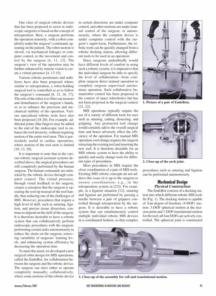
The EndoBot consists of a docking sta-tion into which different robotic MIS toolsfit (Fig. 1). The docking station is capableof four-degree-of-freedom (4-DOF) mo-tion: 3-DOF spherical motion at the inci-sion point and 1-DOF translational motionfor the tool; all four DOFs are actively con-trolled. The spherical joint is constructed
January/February 2001 IEEE ENGINEERING IN MEDICINE AND BIOLOGY 95
1. Picture of a pair of EndoBots.
2. Close-up of the arch joint.
3. Close-up of the assembly for roll and translational motion.

based on a pair of motor-driven semicircu-lar arches (for yaw and pitch), and a sleevethat can roll and translate (using a leadscrew). Figure 2 provides a close up viewof the arch joint and the two motors for thepitch and yaw motion. Figure 3 shows themotors and gearing to drive the roll motionand the lead screw for the translational mo-tion. Figure 4 shows one of the instru-mented tools, with pneumatic hosesattached. All motors in the docking stationare back-drivable, so when not energized,the surgeon can use the control handle tomove the docking station assembly alongall four axes: roll-pitch-yaw about the inci-sion point, and translation along the toolz-axis. The docking stations are passivelysupported on stands. Each docking stationcontains a surgical handle with control but-tons for direct surgeon manual operation.The control buttons allow the surgeon tocontrol both the docking station and theMIS tools.
The center of rotation of the arch jointsand the tool (intersection of the tool x, y, zaxes) is at the incision point of the patient.Therefore, the motion of the docking sta-tion (roll, pitch, and yaw [rotation about z,y, and x axes, respectively]), and the tooltranslational motion (corresponding to thetranslational motion of the tool housing)
will not cause any tissue tearing at theincision point.
The end tool may contain one or twoon-off type actuators (electrically orpneumatically controlled) and can operateas stand-alone or powered by battery, bycompressed air cartridge, or by an umbili-cal power cord or gas hose. Each tool canslip through the locking hole in the toolhousing and the sleeve and be locked intothe tool housing via a locking pin. Anymotion of the docking station will then re-sult in a corresponding motion of thelocked tool.
The motion of these tools (for suturing,dissecting, cutting, grasping, drilling, andreaming) is driven by rods connecting tothe tool motors. One rod with translationalmotion is needed for the dissecting, cut-ting, and grasping tools; three rods withtranslational motion are used for the su-turing tool; and one rod with rotationalmotion is used for the drilling and reamingtools. The tool motors are also com-manded by the control computer.
Figure 5 shows one of the authors’manually operated two-endoscopic ro-botic docking stations with detachable ro-botic MIS tools. The tools are typicallyinserted into the abdomen of the patient onthe surgical table by the surgeon. An en-doscopic camera is inserted into the pa-tient through a third incision point. Theendoscope is connected to a displayscreen for the surgeon to view the interiorof the patient.
KinematicsDue to the spherical joint being at the
incision point, the kinematics is straight-forward. The schematic of an EndoBot isas shown in Fig. 6. We parameterize thejoint vector q as yaw angle (rotation aboutthe inertial x-axis), pitch angle (rotationabout the inertial y-axis), roll angle (rota-tion about the body z-axis), and transla-tion (extension of the tool along the body zaxis). The end effector location isparameterized by the Cartesian positionand the roll angle. The forward kinematicsis easily derived using simple trigonome-try (we have applied the general product
of exponential formula from the rigidmultibody formulation [24] based on ourpast work in robotics):
xr
r
x
y
z
c s q
s q
c c q
TT
T
=φ
=
= −
1 2 4
1 4
1 2 4
φ = q3. (1)
Note that s1 denotes sin( )q1 , c1 denotescos( )q1 , etc. The inverse kinematics isalso straightforward:
( )
q r x y z
q x z
q yc z
q
T42 2 2
2
1 2
3
= = + +
== −
= φ
atan2
atan2
( , )
,
. (2)
The Jacobian is needed in the task spacecontrol, and it may be obtained by differ-entiating the forward kinematics [Eq. (1)]:
J
s s q c c q c s
c q s
s c q c s q c c=
−− −
− −
1 2 4 1 2 4 1 2
1 4 1
1 2 4 1 2 4 1 2
0
0 0
0
0 0 1 0
.
(3)
When det( )J = 0, the robot is in a singularconfiguration, implying that there is cer-tain task space motion that cannot beachieved (and, conversely, small task
96 IEEE ENGINEERING IN MEDICINE AND BIOLOGY January/February 2001
4. The instrumented tool.
It is desirable for an
MIS robotic system to
be able to quickly and
easily change tools for
different types of
procedures.
5. Manual operation of EndoBots.

space motion would result in large jointspace motion). In the case of EndoBot:
det( )J c q= 1 42 . (4)
This means singular configuration occurswhen q1 = ±π or q1 0= . In the first case,the EndoBot would have to lie horizontal;and in the second case, the tip of theEndoBot would have to be in the center ofthe spherical joint. Both cases are outsideof the normal workspace and therefore donot have to be considered.
The above kinematics relies on preciseknowledge of the EndoBot with respect tothe world frame. An initial calibrationprocedure needs to be carried out to en-sure the accuracy of this information.
DynamicsThe dynamics of the EndoBot may be
obtained using either Lagrangian or New-ton-Euler analysis. The dynamics are inthe following general form:
( ) ( )M q q C q q q G q N q( ) �� , � � ( ) �+ + + = τ
(5)
where M is the mass-inertia matrix, C isthe Coriolis and centrifugal forces, G isthe gravity load, N is the friction, and τ isthe joint torque. Due to low speed opera-tion, we will ignore C. We will separatelyconsider the identification of the frictionparameters in N and other dynamic pa-rameters (in M and G).
Friction ModelFor most servo applications, joint fric-
tion is the main limitation to precision andperformance, and it can lead to stick-slipmotion, static positioning errors, or limitcycle oscillations. Systematic lubricationshould be implemented starting in the de-sign stage to reduce frictional disturbance.Stiff (high gain) position control can re-duce the frictional positioning error, pos-sibly at the expense of creating adestabilizing effect. Integral action is alsoa common alternative used to reduce thesteady state error. When the friction be-havior can be predicted, it may be com-pensated for by feedforward com-pensation, as in Fig. 7.
Friction compensation requiresknowledge of the friction model and cor-responding parameters. Friction is usuallymodeled as a map between an instanta-neous friction force and velocity. Typicalfriction models are shown in Fig. 8. Wehave chosen to use a Coulomb plus vis-
cous friction model for each joint [case(b)]:
( ) ( )τ f c vq F sgn q F q� � �= + . (6)
In [25], a method of finding the frictionparameters Fc and Fv experimentally wasproposed. A series of constant torque in-puts is applied to the joint, and the corre-sponding steady-state joint velocities arerecorded. Fitting the steady-state velocityversus input torque to a straight line thengives both Fc and Fv . However, thismethod is not directly applicable here, dueto the gravity load and limited workspace.Instead, we apply least square identifica-tion to all of the dynamics at the sametime, as described below.
Identification ofDynamic Parameters
To identify the dynamic parameters,we move one joint at a time. The equationof motion is given by:
( )Iq mglsin q F sgn q F qc v�� ( ) � �+ + + = τ(7)
Considering the total energy, we obtain:
( ) ( )( )( )( ) ( )( )
τTb at
t
b a
qdt q t q t
I q t q t mlg
q dtF
a
b � � �
cos cos
�.
= −
+ −
+
∫1
22 2
( ) ( )( ) ( )((
( )( ))
c vt
t
t
t
b a b
q
q dtF
q t q t g q t
q t
a
b
a
b +
= −
−
∫∫ �
� �
cos
2
2 21
2cos
� �q dt q dt
I
ml
F
F
t
t
t
t
c
v
a
b
a
b∫ ∫
2
(8)
A multi-sinusoid input torque signal isused, and the parameters are found bysolving the resulting least square problem.
Control ArchitectureControl Modes
The control architecture is designed toallow the surgeon and the robot to collab-orate in a range of programmable modes.
Manual ModeIn the manual mode, the amplifiers for
the four motors of the docking station aredisabled. The motors are back-drivable,allowing the surgeon to manually movethe tip of the tool in the roll-pitch-yaw andtranslation directions. The surgeon canuse the control buttons on the handle to ac-tivate tool motion. The manual mode isuseful in the following situations:
a) It allows the surgeon to build confi-dence in the robotic device.
b) It allows the surgeon to perform del-icate operations that have not been pro-grammed into the control computer.
c) It allows the surgeon to teach thecontrol computer new procedures (bycoding the docking station and tool mo-tion under the surgeon’s command intothe control computer memory).
d) It allows the surgeon to use the robotdevice as an input; e.g., pointing out startand end points for procedures such as su-turing or cutting, locating the starting
January/February 2001 IEEE ENGINEERING IN MEDICINE AND BIOLOGY 97
h4
h2
h1
q4
q2
q1
h3
E4,e Zo
qo
ED,1,2,3 Yo
Yo
6. Kinematics schematic of an EndoBot.
Controller Robot Dynamicswith Friction
Friction Compensation
++
τ
τƒ
q.
τ ƒƒ = ( )q.
7. Model-based friction compensation.

point and motion vector for drilling, andindicating the location of a knot.
Points c and d above are possible sincethe encoders for joint measurement re-main active (continuously providing mea-
surements to the control computer) duringthe manual operation.
Shared ControlIn the shared control mode, the sur-
geon controls some axes while the robot
controls other axes. This is useful in thefollowing situations:
a) The surgeon wants to move the toolalong the tool axis for drilling. Theroll-pitch-yaw rotation of the docking sta-tion is computer controlled, while the sur-geon manual ly controls the tooltranslational motion and manually oper-ates the tool (for example, for drilling orcutting).
b) The surgeon wants to control the tipof the tool along a straight line, e.g., toperform precision cutting and stitching.The computer actively controls the tool tostay in a valley along which the surgeon isfree to move the docking station and oper-ate the tool.
The surgeon may specify the directionof manual control through a 3-D input de-vice. Our current implementation allowsthe surgeon to manually operate one ofthe EndoBot tools as the pointing deviceand to use a foot pedal to register the se-lected points.
Autonomous ModeAs the surgeon gains greater confi-
dence in using the EndoBots, certain pro-cedures may be performed autonomously,though still under supervision. For exam-ple, the surgeon may specify an autono-mous sutur ing task with al l theintermediate points. With the graspingtool in one EndoBot and another graspingtool in the other EndoBot, the controlcomputer can command the robots to per-form the required suture task autono-mously. The key step here is to generatethe desired robot tool motion, as discussedbelow. Due to the deformability of softtissues, each new suture point would needto be confirmed by the surgeon, who canmodify the suture location if necessary.
Control AlgorithmsManual Mode
For the manual mode, the controlleronly provides gravity compensation, soeven when the EndoBot is in a tilted posi-tion, it will not fall:
τ = +G q N q( ) ( ).
Autonomous ModeIn the autonomous mode, the desired
Cartesian motion is converted to the jointmotion through inverse kinematics. Aproportional-derivative (PD) joint-levelcontroller with friction and gravity com-pensation is then applied to track the re-quired motion [26]. The controller torqueis of the following form:
98 IEEE ENGINEERING IN MEDICINE AND BIOLOGY January/February 2001
τ
ττ
τ
(a) Coulomb Friction
q.
q.
q.
q.
(b) Coulomb + Viscos Friction
(c) Stiction + Coulomb + Viscos Friction (d) Stribeck Friction
8. Classical friction models.
15
15
15
15
10
10
10
10
5
5
5
5
−5
−5
−5
−5
0
0
0
0
−10
−10
−10
−10
−15
−15
−15
−15
0
0
0
0
2
2
2
2
4
4
4
4
6
6
6
6
8
8
8
8
Time(a)
Time(c)
Time(b)
Time(d)
Pos
ition
[deg
]P
ositi
on[d
eg]
Pos
ition
[deg
]P
ositi
on[d
eg]
9. Friction compensation. (a) First joint position without friction compensation. (b)Second joint position without friction compensation. (c) First joint position withfriction compensation. (d) Second joint position with friction compensation.

( )( )( )
( )
τ = − −
− −
+ +
−
−
K q k x
K q J q x
G q N q
p Td
d Td
1
1( ) �
( ) �
(9)
where xTd is the desired motion for thetask coordinate xT , k−1 is the inverse kine-
matics, and J−1 is the inverse Jacobianmatrix. Ignoring the Coriolis/centrifugalterms (due to small velocity), theclosed-loop system is of the form:
Me K e K ed p�� �+ + = 0 . (10)
Due to the high gear ratio, M is approxi-mately constant and diagonal. The PDgains K p and Kd are chosen to be diagonaland provide critical damping.
We have found that friction compensa-tion (especially Coulomb friction) is ofcritical importance to tracking accuracy.In Fig. 9, tracking error improvement af-ter friction compensation is evident.
To assess the performance for Cartesianspace motion tracking, we conducted exper-iments consisting of circular reference tra-jectories. The cases shown here wereperformed with three difference angular ve-locities and sizes of the desired circle:
ωωω
1
2
3
01 0 62
0 25 157
0 5
===
. ( . )
. ( . )
. (
Hz rad sec
Hz rad sec
Hz 314
2 5
5
10
1
2
3
. )
.
rad sec
mm
mm
mm.
r
r
r
===
Gravity and friction compensationwere included in all experiments. Figure10 shows the composite tracking plots.Table 1 quantitatively summarizes thetracking performance of the joint spacecontroller. It is clear that higher angularvelocity results in large tracking error.The tracking performance will be used inthe motion planning for complete autono-mous motions (e.g., knot tying) to ensurethe motion plan takes the tracking uncer-tainty into account.
Shared Control ModeIn the shared control mode, the sur-
geon specifies motion constraints (direc-tions where there should be no motion)and the complementary free motion direc-tion. We will consider both joint spaceand direct Cartesian space implementa-tions. Let the motion constraint on the taskcoordinate xT be specified as:
( )x c xc T= = 0 (11)
where c is a constraint function. Let f ( )⋅ bethe complement of c so that:
( ) ( )( )d x
c x
f xTT
T
=
(12)
is a diffeomorphism (i.e., d is one-to-oneand onto, and d and d − 1is a straight linethrough the center of the spherical joint).Let the straight line be parameterized as:
x
a
y
a
z
a1 2 3
= =
Then the constraint function is:
( )c xa a
a a
xT T=−
−
1 10 0
10
10
1 2
1 3
.
(13)
The free motion function f may be chosento be any function that is not linearly de-pendent on c. However, to avoid coupling,it is in generally desirable to choose f to beorthogonal to c. In this case, coupling, it isin general desirable to choose f to be or-thogonal to c, so, we may choose f to be:
( )f xa a a
T =
1 2 3 0
0 0 0 1.
(14)
If we use the same joint space controller asdescribed above, shared control can beachieved by removing the free motioncomponent in the desired task space tra-jectory. Specifically, let q be the mea-sured joint angle. The desired free motionshould be the same as the actual free mo-tion; therefore f x f k qTd( ) ( ( ))= . Theconstraint motion is required to be zero;
January/February 2001 IEEE ENGINEERING IN MEDICINE AND BIOLOGY 99
15
10
5
0
−5
−5
−10
−10−15
−15
Circle Tracking
y[m
m]
0 5 10 15
x [mm]
10. Experimental result of circle tracking.
Table 1. Circle Tracking Error
Angular Velocity r1 (mm) r2 (mm) r3(mm)
ω1 0.409 0.463 0.487
ω2 0.419 0.551 0.588
ω3 0.445 0.544 0.757

therefore, c xTd( ) = 0. The desired taskspace set point can then be obtained from:
( )x df k qTd =
−1 0
( ) (15)
where d is from Eq. (12). The desired taskspace velocity may be found similarly:
��
xJ
J J JTdc
f f q=
−10
(16)
where J c qc = ∂ ∂/ and J fa qf = ∂ ∂/ .Once xTd is found, the same joint spacecontroller [Eq. (9)] may be used.
It is also possible to servo directly,based on the task space error. In this case,the controller is of the following form[27]:
( )( )
( )
τ =
− −
+ +
− −J J J JM J J
K x K x
G q N q
TcT
cT
cT
p c d c
1 1
�
( ) � . (17)
The operator moves the instrument us-ing the handle, and the experimental re-sults of constraining the EndoBot tool tipto a line and a circle are shown in Figs. 11and 12, respectively. It is important to
tune the feedback gains (especially theproportional gain) to give the operator theright feel (tight but no oscillation). Tables2 and 3 show the measured operator ap-plied force versus the path deviation aswell as the effective stiffness.
Ligation AlgorithmFrom closing the wound with an ant’s
head in ancient times, to the laparoscopicstitching with absorbable material today,suturing has a long history and is one ofthe most difficult tasks in MIS. In this sec-tion, we present results on autonomoussuturing using a pair of EndoBots, onehaving a grasping tool and the other astitching tool. Both tools are built fromdisposable tools made by US SurgicalCorp. (USSC). The mechanical handlesare cut and mated with pneumatic drives.The grasping tool can be commandedwhile open or closed. The stitching toolcontains two jaws, each of which can lockin the needle. The tool can also pass theneedle between the jaws by a foot-pedalcommand (effective in making a stitch).
The challenges of suturing include:� Only the needle position is known.
The thread position is not directlymeasured.
� The thread and the material being su-tured (tissues) are both flexible.
� The workspace is limited.In this section, we will consider three
algorithms for automatic ligation. Thefirst uses a standard manual stitching tool,instrumented for robotic operation. Thesecond modifies the grasping tool with aflexible hook, to facilitate the knot-tyingprocess. The third modifies the graspingtool in order to have an articulated finger.Currently, the first and second methodshave been implemented, and the last is un-der development.
Algorithm 1The key factor in tying a simple knot is
that if the suture can be placed over thejaw carrying the needle, then a loop can beformed by passing the needle to the otherjaw. For a human surgeon, this step is per-formed by putting the jaws over the threadand then passing it through the needle.This is not possible for the EndoBot, sincethe thread is flexible and its position is notdirectly measured. Instead, we use the ri-gidity of the grasper to guarantee that thesuture is placed over the jaw. Automatictying of a simple knot can then be accom-plished through the following steps(shown schematically in Fig. 13):
100 IEEE ENGINEERING IN MEDICINE AND BIOLOGY January/February 2001
0
−0.02
−0.04
−0.06
−0.08
−0.1
−0.12
−0.14
−0.16
−0.18
−0.2
z[m
]
00.05
0.10.15
0.2 0.2 0.150.1
0.050
x [m]y [m]
Desired Trajectory
Actual Trajectory
11. Shared control experiment with a constrained line.
0
−0.02
−0.04
−0.06
−0.08
−0.1
−0.12
−0.14
−0.16
−0.18
−0.2
z[m
]
00.05
0.10.15
0.2 0.2 0.150.1
0.050
x [m]y [m]
Desired TrajectoryActual Trajectory
12. Shared control experiment with a constrained circle.

1. Make a single stitch near the woundand pull out the suture so that a small tailremains. This may be done manually bythe surgeon either using the manual modeor semi-autonomously. In the latter case,the surgeon manually grasps both sides ofthe wound with the grasper and uses thefoot pedal to command the stitcher tomake a stitch. The stitcher then retractsuntil a specified amount of suture has beenpulled through the suturing point.
2. Grab the suture tail with the graspertip. This may be done manually by the sur-geon using the manual mode orsemi-autonomously. In the latter case, thegrasper predicts the location of the suturetail, based on the location and direction ofthe suture performed in the previous step.
3. Move the stitcher so that the openjaw (the jaw without the needle) touchesthe front of the grasper stem. This locationshould be as far up the grasper stem as theworkspace will allow. Denote the point ofcontact between the stitcher jaw andgrasper stem as P.
4. Rotate the stitcher 180° about the axisOP, where O is the center of the sphericaljoint. The angle formed between the grasperand the stitcher has to be sufficiently large toguarantee that the tip of the needle does nothit the stem of the grasper. At the comple-tion of this step, the thread has to lay overthe open jaw. Otherwise, the surgeon wouldhave to intervene manually.
5. Move the stitcher toward the grasperuntil the grasper stem is within the openjaw of the stitcher. The grasper stem canfit through the jaw opening, but it is toothick for the stitcher jaws to close. Thestitcher, therefore, needs to move alongthe grasper stem until it reaches thegrasper tool tip.
6. Rotate the grasper so that its narrowside faces the jaw opening. The stitchercan now close and pass the needle to theother jaw.
7. Retract the stitcher to tighten theknot.
The above procedure creates a simpleknot. Two simple knots may be combinedto form a square knot. However, the sec-ond simple knot must be the mirror imageof the first, otherwise a “granny” knot isformed, which is not secure. The onlymodification is that at Step 3, the stitchershould touch the back of the grasper stem;and in Step 4, the rotation should be−180°. The square knot procedure maythen be repeated to form a surgeon’s(square) knot
The above procedure works well mostof the time in the laboratory but has thefollowing drawbacks:
� In Step 4, a large angle is required be-tween the two instruments. For knotsnear the center of the workspace, thismay not be feasible.
� Because of errors in positioning, thethin suture thread could fall betweenthe open jaw and the grasper stem.
� During the retraction stage, thethread could get tangled.
Ligation Algorithm 2The first algorithm is a step toward au-
tomatic laparoscopic suturing and knot-ting, but it suffers several drawbacks as torender the procedure less than robust. Toimprove the procedure, we made a smallmodification of the conventional graspinginstrument. The key factor here is that ifwe can hold on to any part of the suture at aknown position, the rotation of the stitcherwould be unnecessary. To achieve this,we added a reciprocating actuator con-nected to a flexible hook over the grasperhinge so that the hook can be extended orextracted as needed (Fig. 14).
The simple knot algorithm is nowmodified as described below (shownschematically in Fig. 15, with picturesfrom an actual experiment in Fig. 16):
1. Perform Steps 1-2 of Algorithm 1.2. Extend the flexible hook. Move the
stitcher over the hook from the front toback so that the suture hangs over thehook.
3. Perform Steps 5-6 of Algorithm 1.4. Retract the flexible hook.5. Retract the stitcher to tighten the
knot.Again, a mirror image of the first simple
knot is needed to ensure a secured squareknot. This is done by replacing the motionover the hook to back to front (instead of
front to back). This algorithm does nothave the angle limitation as in Algorithm 1.The motion over the hook can be designedso that the thread is always snared by thehook, thus the positioning requirement isnot as tight as before. Finally, since thehook is close to the grasper tip, the graspercan retract by a small amount so as to avoidthread tangling.
Ligation Algorithm 3The two ligation algorithms described
above require the use of the special stitch-ing tool designed for endoscopic surgeries(the EndoStitch by USSC). For many sur-geries, for example anastomosis (con-necting between blood vessels), asemi-circular needle is used with twograspers. For such cases, the algorithmspresented so far are not applicable. In thissection, we consider another type ofgrasper (such as in [20]), which containsan additional universal joint. Then, form-ing a loop can be accomplished by justwrapping the thread around the bent arm.
The detailed sequence for tying a sim-ple knot is described below (Fig. 17):
1. Hold the needle in the needleholder and make a single stitch near thewound. Pull out the suture so that itleaves a small tail.
2. Move the needle holder around thebent grasper tip to create a loop.
3. Move the two instruments togetherso that the bent grasper grabs the tail of thesuture while maintaining the loop wrap-ping around the bent stem.
4. Retract the grasper to tighten thesimple knot.
To form a square knot, the second sim-ple knot needs to be done with the loopformed in the opposite direction. Note thatthe only reason that a bent tip grasper isneeded is to ensure that the loop does notslip off the grasper. This algorithm has
January/February 2001 IEEE ENGINEERING IN MEDICINE AND BIOLOGY 101
Table 2. Effective Constraint Stiffness for Linear Trajectory
Max (|e|)[m]
Max (| | )Fc[N]
Effective Stiffness, K e[n/m]
e c1 0.0013 8.1838 6268
e c 2 0.00062 9.763 15570
Table 3. Effective Constraint Stiffness for Circular Trajectory
Max (|e|)[m]
Max (| | )Fc[N]
Effective Stiffness, K e[N/m]
e c1 0.0032 102.02 31400
e c 2 0.002 3.49 1770

several advantages over the previousones. There is no limitation on the relativepositions between the two endoscopic in-struments, and the use of a special stitch-ing tool (and the associated needles) is notrequired. This algorithm can also be ex-tended to more general knots. For exam-ple, looping twice around the bent armwould make a friction knot. We are also
currently evaluating the possibility of us-ing the grasper with a hook, described inAlgorithm 2, to implement this algorithm.
ConclusionThis article has presented the mechani-
cal design, kinematics and dynamics anal-ysis, control architecture, experimentalresults, and algorithmic implementation
of a robotic system assisting in endo-scopic surgery. Innovations in this systeminclude a mechanical design consistentwith natural kinematics constraint (at theincision point), interchangeable tools,variable level of autonomy in shared sur-geon/robot control, and novel algorithmsfor ligation.
For successful clinical deployment,many other issues need to be addressed.Foremost is the safety issue. All possiblefault conditions and contingencies wouldneed to be considered; e.g., power failure,computer malfunction, work space varia-tion for different patients, etc. Anotherimportant issue is the design of theman-machine interface. In order for sur-geons to gain comfort and trust with sucha system, the mechanical interface, suchas the type of handle and placement ofcontrol buttons, and the electrical inter-face, such as specification of differentcommands, would need to carefully de-veloped with strong input from surgeons.
In terms of further technical develop-ment, we are focusing on making the au-tonomous surgical procedures morerobust. Careful modeling and control ofthe thread tension is critical in avoidingtissue tearing and pulling the needle fromthe stitcher or the holder. Ensuring knottightness is needed to prevent leakage atthe suture. Finally, the impact of differentwork volumes (due to variation amongpaients) is also under investigation.
Hyosig Kang receivedthe B.S. and M.S. de-gree in precision me-chanical engineeringfrom Hanyang Univer-sity, Seoul, Korea, in1989 and 1991, respec-tively. From 1991 to1997 he was a research
scientist at the Korea Institute of Scienceand Technology, Seoul, Korea, where heworked on real- t ime control andteleoperation. Currently, he is pursuingthe Ph.D. degree in mechanical engineer-ing at Rensselaer Polytechnic Institute.His research interests are in the areas ofsurgical robot and force control.
John Ting-Yung Wenreceived his B.Eng.from McGill Universityin 1979, his M.S. fromUniversity of Illinois in1981, and a Ph.D. fromRensselaer PolytechnicInstitute in 1985, all inelectrical engineering.
102 IEEE ENGINEERING IN MEDICINE AND BIOLOGY January/February 2001
(a)
(b)
(c)
(d)
13. Autonomous simple knot-tying algorithm (Algorithm 1).

From 1981 to 1983, he was a system engi-neer at Fisher Control Company,Marshalltown, IA, where he developed aplant-wide coordination controller of apulp and paper plant. From 1985 to 1988,he was a member of the technical staff atthe Jet Propulsion Laboratory, Pasadena,CA, where he worked on the modelingand control of large flexible structures andmultiple-robot coordination. Since 1988,he has been with the Department of Elec-trical, Computer, and Systems Engi-neering at Rensselaer PolytechnicInstitute, where he is currently a profes-sor. He is also a member of the Center forAutomation Technologies. His current re-search interests are in the areas of distrib-uted real-time control, nonlinear control,parallel robots, and robotics for medicalapplications. Dr. Wen is a senior memberof IEEE.
Address for Correspondence: John T.Wen, Center for Automation Technol-ogies, Rensselaer Polytechnic Institute,Troy, NY 12180. E-mail: [email protected].
References1. Way LW, Bhoyrul S, and Mori T: Funda-mentals of Laparobotic Surgery. New York:Churchill Livingstone, 1995.
2. Cao C, MacKenzie C, and Payandeh S: Taskand motion analyses in endoscopic surgery. In:Proc ASME IMECE Conference: 5th AnnualSymposium on Haptic Interfaces for Virtual Envi-ronment and Teleoperator Systems, Atlanta, GA,1996, pp. 583-590.
3. Funda J, LaRose DA, and Taylor RH: Sys-tem and method for augmentation of endoscopicsurgery. U.S. Patent 5,417,210, 1995.
4. Green PS: Method for telemanipulation withtelepresence. U.S. Patent 5,631,973, 1994.
5. Wang Y, del’Giudice HA, and Laby KP: Au-tomated endoscope for optimal positioning. U.S.Patent 5,754,741, 1998.
6. Mitsuishi M, Iizuka Y, Watanabe H,Hashizume H, and Fujiwara K: Remote opera-tion of a micro-surgical system. In: Proc IEEE Int.Conf. Robotics and Automation, Detroit, MI, May1999, pp. 1570-1576.
7. Sastry S, Cohn M, and Tendick F:Millirobotics for remote, minimally invasive sur-gery. Robotics and Autonomous Syst 21(3):305-316, 1997.
8. Schenker PS, Das H, and Ohm TR: A new ro-bot for high dexterity microsurgery. In: N.Ayache (Ed): Computer Vision, Virtual Realityand Robotics in Medicine. First Int Conf,CVRMed’95. Berlin: Springer-Verlag, pp.115-122, 1995.
9. Taylor RH, Mittelstadt BD, Paul HA,Hanson W, and Kazanzides P: An image-di-rected robotics system for precise orthopaedic
January/February 2001 IEEE ENGINEERING IN MEDICINE AND BIOLOGY 103
14. Flexible hook for catching the suture.
(a)
(b)
(c)
(d)
15. Schematic for Algorithm 2 (autonomous simple knot-tying algorithm).

surgery. IEEE Trans Robot Automat 3(10):261-275, June 1994.
10. Tendick F, Sastry S, Fearing R, and CohnM: Applications of micro-mechatronics in mini-mally invasive surgery. IEEE/ASME TransMechatronics 3(1): 34-42, 1998.
11. Funda J, Taylor R, Gruben K, and LaRosD: Optimal motion control for teleoperated surgi-cal robots. In: Telemanipulator Technology andSpace Telerobotics, Boston, MA: SPIE, volume2057, pp. 211-222, Sept. 1993.
12. Wang Y, Uecker DR, Laby KP, Wilson J,Jordan S, and Wright J: Method and apparatus
for performing minimally invasive cardiac proce-dures. U.S. Patent 5,762,458, 1998.
13. Intuitive Surgical: Robots will enter the OR.Global Design News: Engineering News, June1999.
14. Tendick F, Downes MS, Cavusoglu MC,and Way LW: Development of virtual environ-ments for training skills and reducing errors inlaparoscopic surgery. In: Proc SPIE Int Symp Bio-logical Optics (BIOS’98), San Jose, CA, Jan.1998, pp. 36-44.
15. Tendick F and Cavusoglu MC: Human-ma-chine interfaces for minimally invasive surgery.In: Proc Int Conf IEEE Engineering Medical Bi-ology Soc, Chicago, IL, Oct. 1997, pp. 2771-2776.
16. Goradia TM, Taylor RH, and Auer LM:Fine microsurgical drilling: Use of a robotic ma-nipulator for skull base neurosurgery. In: ProcCongress of Neurological Surgeons, New Or-leans, LA, 1997.
17. Satava RM and Jones SB: Telepresence sur-gery. In: RM Satava (Ed), Cybersurgery: Ad-vanced Technologies for Surgical Practice, NewYork: Wiley, pp. 141-154, 1998.
18. Faraz A and Payandeh S: A robotic casestudy: Optimal design for laparoscopic position-ing stands. In: Proc IEEE Int Conf Robotics andAutomation, Albuquerque, NM, Apr. 1997, pp.1553-1560,
19. Cohn M, Crawford LS, Wendlandt JM,and Sastry SS: Millirobotics for telesurgery. In:Proc First Int Symp Medical Robotics and Com-puter Assisted Surgery, Pittsburgh, PA, Sept.1994, pp. 184-189.
20. Madhani AJ and Salisbury JK: Wrist mech-anism for surgical instrument for performing min-imally invasive surgery with enhanced dexterityand sensitivity. U.S. Patent 5,797,900, 1998.
21. Hayati SA and Venkataraman ST: Bilevelshared control for teleoperators. U.S. Patent5,086,400, 1992.
22. Backes PG: Dual-arm generalized compliantmotion with shared control. U.S. Patent5,336,982, 1994.
23. Hill JW, Green PS, Jensen JF, Gorfu Y, andShah AS: Telepresence surgery demonstrationsystem. In: Proc IEEE Int Conf Robotics and Au-tomation, San Diego, CA, May 1994, pp.2302-2307.
24. Murray RM, Li Z, and Sastry SS: A Mathe-matical Introduction to Robotic Manipulation.Boca Raton, FL: CRC, 1994.
25. Armstrong-Helouvry B: Control of Machineswith Friction. Norwell, MA: Kluwer, 1991.
26. Wen JT and Bayard DS: A new class of con-trol laws for robotic manipulators. Part I:Non-adaptive case. Int J Control, 47(5):1361-1385, 1988.
27. Wen JT and Murphy SH: Position and forcecontrol of robot arms. IEEE Transactions Auto-mat Control 36(3): 365-374, Mar. 1991.
104 IEEE ENGINEERING IN MEDICINE AND BIOLOGY January/February 2001
16. Autonomous simple knot-tying algorithm 2 photographs.
17. Autonomous simple knot-tying algorithm 3.