robotic roadway message and symbol painter implementation · robotic roadway message and symbol...
TRANSCRIPT

Ryan G. Rosandich, Principal InvestigatorDepartment of Mechanical and Industrial Engineering
University of Minnesota Duluth
September 2016
Research ProjectFinal Report 2016-31
Robotic Roadway Message and Symbol Painter Implementation

To request this document in an alternative format, such as braille or large print, call 651-366-4718 or 1-800-657-3774 (Greater Minnesota) or email your request to [email protected]. Please request at least one week in advance.

Technical Report Documentation Page 1. Report No. 2. 3. Recipients Accession No.MN/RC 2016-314. Title and Subtitle 5. Report Date
Robotic Roadway Message and Symbol Painter Implementation September 20166.
7. Author(s) 8. Performing Organization Report No.Ryan G. Rosandich9. Performing Organization Name and Address 10. Project/Task/Work Unit No.Department of Mechanical and Industrial EngineeringUniversity of Minnesota Duluth1305 Ordean Ct., 105 Voss-Kovach HallDuluth, MN 55812
CTS #201702111. Contract (C) or Grant (G) No.
(c) 99008 (wo) 248
12. Sponsoring Organization Name and Address 13. Type of Report and Period CoveredMinnesota Department of TransportationResearch Services and Library395 John Ireland Boulevard, MS 330St. Paul, MN 55155-1899
Final Report14. Sponsoring Agency Code
15. Supplementary Noteswww.mndot.gov/research/reports/2016/201631.pdf16. Abstract (Limit: 250 words)The goals of this project were to develop a large-scale vehicle-mounted robotic roadway message painterthat could be run by a single operator, and to develop software to enable the device to automatically paintvarious messages and symbols on roadways. A completely new articulated robot arm was design andconstructed, complete with a control system, operator interface, paint delivery system, truck mount, andmobile power supply. The system was thoroughly tested, and programs were written to allow the robot topaint several symbols and messages on a roadway. The programs were tested and fine-tuned indoors, andthen tested outdoors once the robot was mounted on a truck. An important finding of this research is thatthe traditional markings used by MnDOT are not ideal for robot application. Robotic painting can bebetter accommodated by altering the outlines of the markings somewhat, and by using directional hashlines to fill in the symbols rather than solid paint. These machine-made markings are faster to apply anduse less paint, and in the end may be more effective for motorists than the traditional markings. Therobotic roadway painter developed during this project has the potential to completely change the way inwhich markings are painted on roadways. The device has demonstrated the ability to paint roadwaymarkings using an articulated robot arm mounted on the front of a vehicle. Expected benefits of thedeployment of such a device include improved operator safety, improved productivity, and improvedflexibility in roadway marking operations.
17. Document Analysis/Descriptors 18. Availability Statementpainting, robotics No restrictions. Document available from:
National Technical Information Services,Alexandria, Virginia 22312
19. Security Class (this report) 20. Security Class (this page) 22. PriceUnclassified Unclassified
21. No. of Pages 110

Robotic Roadway Message and Symbol Painter Implementation
Final Report
Prepared by: Ryan G. Rosandich, Ph.D.
Department of Mechanical and Industrial Engineering University of Minnesota Duluth
September 2016
Published by: Minnesota Department of Transportation
Research Services & Library 395 John Ireland Boulevard, MS 330
Saint Paul, MN 55155
The contents of this report reflect the views of the authors, who are responsible for the facts and the accuracy of the information presented herein. This report represents the results of research conducted by the authors and does not necessarily represent the views or policies of the Minnesota Department of Transportation or the University of Minnesota.
The authors, the University of Minnesota and the Minnesota Department of Transportation, do not endorse products or manufacturers. Any trade or manufacturers’ names that may appear herein do so solely because they are considered essential to this report.

Acknowledgments
This project was funded by the Minnesota Department of Transportation (MnDOT). The author would like to thank the following MnDOT employees for their support of the project:
Alan Rindels
Randy Reznicek
Bruce Daniel
Robert Ege

Table of Contents CHAPTER 1: INTRODUCTION ................................................................................................ 1
1.1 The Seed Grant Project ......................................................................................................... 1
1.2 The Prototype Project ........................................................................................................... 1
1.3 Related Development Projects by Others ............................................................................. 1
1.4 The Current Implementation Project .................................................................................... 2
1.5 Expected Benefits ................................................................................................................. 2
1.6 Intellectual Property Protection ............................................................................................ 2
CHAPTER 2: METHODOLOGY .............................................................................................. 3 2.1 Painter Frame ........................................................................................................................ 4
2.2 Vehicle Mounting System..................................................................................................... 7
2.3 Motion Control System ....................................................................................................... 10
2.4 Mobile Power Supply ......................................................................................................... 12
2.5 Paint Application System .................................................................................................... 13
2.6 Reflective Bead Application System .................................................................................. 14
2.7 Operator Interface ............................................................................................................... 14
2.8 Painter program development ............................................................................................. 15
2.9 Final Assembly ................................................................................................................... 16
2.10 Field Testing ..................................................................................................................... 19
CHAPTER 3: RESULTS ........................................................................................................... 20 3.1 System Test Results ............................................................................................................ 20
3.2 Painting Results .................................................................................................................. 20
CHAPTER 4: CONCLUSIONS ................................................................................................ 22 4.1 Summary of Conclusions .................................................................................................... 22
4.2 Shortcomings ...................................................................................................................... 22
REFERENCES ............................................................................................................................ 24 APPENDIX A APPENDIX B APPENDIX C APPENDIX D

List of Tables Table 2.1. Major Deliverables ........................................................................................................ 3
List of Figures
Figure 2.1. Gantry concept, top view. ............................................................................................. 4
Figure 2.2. Articulated arm concept, top view................................................................................ 5
Figure 2.3. Articulated arm preliminary design. ............................................................................. 5
Figure 2.4. Robot painter workspace. ............................................................................................. 6
Figure 2.5. Powered joint construction details. ............................................................................... 7
Figure 2.6. Truck mount subsystem. ............................................................................................... 8
Figure 2.7. Robot arm mount subsystem. ....................................................................................... 8
Figure 2.8. Robot arm support subsystem. ..................................................................................... 9
Figure 2.9. Hydraulic jack plate. ..................................................................................................... 9
Figure 2.10. Drive system design details. ..................................................................................... 10
Figure 2.11. Galil motion control board with built-in and servo amplifier. ................................. 11
Figure 2.12. Robot control box. .................................................................................................... 11
Figure 2.13. Mobile power supply. ............................................................................................... 12
Figure 2.14. Robot arm wireway configuration. ........................................................................... 13
Figure 2.15. Graco Magnum X7 pump. ........................................................................................ 13
Figure 2.16. Graco AL airless spray gun. ..................................................................................... 14
Figure 2.17. Operator interface. .................................................................................................... 15
Figure 2.18. Robot assembled for indoor testing. ......................................................................... 16
Figure 2.19. Robot arm mounted to truck. .................................................................................... 17
Figure 2.20. Truck bed with auxiliary equipment......................................................................... 18
Figure 2.21. Truck-mounted robot arm deployed for testing........................................................ 18
Figure 3.1. Painting Results. ......................................................................................................... 21

Executive Summary
This project was undertaken in response to a problem statement which was submitted by the Minnesota Department of Transportation. The goals of the project were to develop a large-scale vehicle-mounted robotic roadway message painter that could be run by a single operator and to develop software to enable the device to automatically paint various messages and symbols on roadways. The design was based partially on a successful trailer-based prototype that was used to demonstrate the feasibility of painting messages and symbols on a roadway. The work for this project was broken into major deliverables representing the design, construction, testing, and reporting steps undertaken to complete the project. The project began with a design concept that included a gantry-style robot that would be attached to the front of a truck. It soon became obvious that this design would have major drawbacks, however, and the concept was changed to an articulated robot arm that would fold flat against the front of the truck. A completely new articulated robot arm was design and constructed, complete with a control system, operator interface, paint-delivery system, truck mount, and mobile power supply. The system was thoroughly tested, and programs were written to allow the robot to paint several symbols and messages on a roadway. The programs were tested and fine-tuned indoors and then tested outdoors once the robot was mounted on a truck.
Since this is the first device of its kind, it naturally has some shortcomings. Slight flexibility in the mounting system and arm joint drives leads to some wobbliness during motion, and this leads to some quality problems with painting operations. Some of the problems could be mitigated by implementing a different control mode, which is possible because the controller has been recently upgraded. Another limitation is that the workspace, although larger than originally proposed, is still too small to paint some of the larger markings like combination arrows and railroad crossings.
Another important finding of this research is that the traditional markings used by MnDOT are not ideal for robot application. Robotic painting can be better accommodated by altering the outlines of the markings somewhat, and by using directional hash lines to fill in the symbols rather than solid paint. These machine-made markings are faster to apply and use less paint, and in the end, may be more effective for motorists than the traditional markings.
The robotic roadway painter developed during this project has the potential to completely change the way in which markings are painted on roadways. The device has demonstrated the ability to paint roadway markings using an articulated robot arm mounted on the front of a vehicle and has helped to determine many of the design parameters necessary to develop a commercially viable unit. The device can be controlled from a laptop computer in the cab of the vehicle by a single operator. Expected benefits of the deployment of such a device include improved operator safety, improved productivity, and improved flexibility in roadway marking operations.

1
CHAPTER 1: INTRODUCTION
This project was undertaken in response to the following problem statement which was submitted by Randy Resnicek of the Minnesota Department of Transportation:
Placing messages onto the roadway surface including stop-walk messages or left or right turn arrows is accomplished using stencils and rollers. Can a robotic message painter be developed whereby messages could be applied automatically from an operator position?
This project built on the success of two previous projects funded by the Northland Advanced Transportation Systems Research Laboratory (NATSRL). The first effort was a seed grant project which demonstrated that robotic painting of roadway symbols was feasible. The goal of the second project was to develop a large-scale functional prototype of a robotic roadway message painter that could be run by a single operator, and to develop software to enable the device to automatically paint various messages and symbols on roadways. The device would then be used to determine the effects of different variables on painting speed and quality, and to demonstrate the feasibility of painting messages and symbols on a roadway.
1.1 The Seed Grant Project A study was completed in June 2008 in order to demonstrate the feasibility of using a robotic actuator to paint roadway markings. The system used an existing robot arm, which was equipped with a standard pavement striping paint sprayer for the duration of the study. This combination was capable of painting symbols, letters, and numbers up to a maximum size of approximately 3 ft. x 3 ft. Software was developed for the system that enabled it to paint a variety of characters and symbols on a simulated roadway. The system was successfully demonstrated in actual painting operations by painting on heavy textured paper to simulate painting on pavement.
1.2 The Prototype Project A prototype development project was completed in September of 2010 [1]. A large-scale trailer-based prototype painter that could paint within a work envelope of approximately 4 ft. x 8 ft. was constructed and tested. The device clearly demonstrated the feasibility of using robotics to paint roadway markings, and helped to determine many of the design parameters necessary to develop a commercially viable unit. The device was controlled from a laptop computer at a safe distance by a single operator. The system was successfully demonstrated in actual painting operations by painting on heavy textured paper indoors, and by painting outdoors on actual pavement.
1.3 Related Development Projects by Others Two projects with similar objectives were found in the literature, one at the Advanced
Highway Maintenance and Construction Technology Research Center at the University of California Davis [2] and the other in the Department of Mechanical Engineering at Korea University [3].

2
U. C. Davis has two systems under development, one that uses a gantry-style robot housed in an enclosed trailer. This system is primarily used to paint photogrammetry symbols (a white X on a black background) on the pavement to support aerial surveys. The other system under development is called the Big Articulated Stenciling Robot, and consists of a large computer-controlled hydraulically powered arm that extends from the back of a truck. The arm can reach over 14 feet, and with it a single operator can conduct automated pavement marking operations from the cab of the truck.
The Korean system consists of a gantry robot with an extended transverse arm that allows lane-width painting. It is also capable of conducting automated pavement marking operations with a single operator.
1.4 The Current Implementation Project Upon observing the results of the prototype project, officials from the Minnesota Department of Transportation suggested that a project be undertaken to implement the robotic painting technology. The major difference between the prototype project and the implementation project was that the device as implemented should be mounted on the front of a vehicle, rather than trailer-based. This led to a complete re-design of the mechanical and motion-control portions of the device, and to a completely new design of a vehicle mounting system. Other aspects of the system, including paint delivery, motion programming, and the operator interface underwent major changes to accommodate the new mechanical configuration. The mobile power supply was also changed from a gasoline-powered generator to a rechargeable battery-based system with a 120 VAC inverter to power the laptop computer, air compressor, and paint pump.
1.5 Expected Benefits This system will completely change the way messages and symbols are painted on a roadway. The initial benefits of this research are in the area of roadway painting, but these benefits could be expanded in the future to include other roadway maintenance areas like automated crack-filling and automated pothole repair. The expected benefits are as follows:
• Improved safety: Fewer workers will be exposed to the work zone for a shorter period of time, and the system can be operated from a safe distance.
• Improved productivity: More rapid painting operations will be conducted with less labor. • Improved flexibility: The system is not limited to stencils but is able to paint virtually
any character or symbol on the roadway. • Future benefits: Expansion of the techniques to other areas like automated crack-filling
and pothole repair.
1.6 Intellectual Property Protection The Office of Technology Commercialization at the University of Minnesota has determined that, although the robotic roadway painter concept does not appear to be patentable, it is still worth protecting since the technology could very likely be licensed and marketed to potential manufacturers. For this reason this report is focused on the results of the research rather than the details of the design, materials and construction of the painting device.

3
CHAPTER 2: METHODOLOGY
The work for this project was broken down into major deliverables, and each of those deliverables involved completing several tasks. Table 2.1 shows the major deliverables for the project. The work done to produce each of the deliverables is detailed in the sections that follow.
Table 2.1. Major Deliverables
Deliverable Description
Painter frame Provides rigid structure to support motion control components and automated paint head. Task includes detailed design and analysis, specification of all components and materials, production of drawings suitable for fabrication, and fabrication.
Vehicle mounting system Provides the mechanical interface between the painter frame and the host vehicle. Device to be retractable to travel position, deployable to operating position, and compliant with all applicable codes and standards. The mount will enable some height adjustment to accommodate unlevel roadways. Task includes detailed design and analysis, specification of all components and materials, production of drawings suitable for fabrication, and fabrication.
Motion control system Provides the means to move the device in a programmable, controlled manner. Includes servo motors, gearboxes, drive system, and servo controller. Task includes specification and procurement of all components and materials and production of drawings suitable for assembly, and assembly.
Paint application system Provides the means to apply paint through an automated paint head that can be turned on and off under program control. Task includes specification and procurement of all components and materials and production of drawings suitable for assembly, and assembly.
Reflective bead application system
Provides the means to dispense reflective beads onto the painted area through an automated device that can be turned on and off under program control. Task includes specification and procurement of all components and materials and production of drawings suitable for assembly,

4
and assembly.
Operator interface Provides the means to manipulate and control the entire device, including the ability to select and execute pre-programmed message and symbol painting routines. The interface will be based on a laptop computer which will communicate to the motion controller via Ethernet.
Final assembly Assembly of all components and systems, mounting on a vehicle, and functional testing in a controlled setting. Task includes assembly of mechanical components, mounting motion control components, installation of paint delivery system, installation of bead delivery system, wiring of all electrical components, and functional testing and fine-tuning.
Field testing Testing under realistic conditions in the field while painting various messages and symbols, fine-tuning the design, and developing standard operating procedures
2.1 Painter Frame The initial concept for the painter frame was a gantry-style system similar to that used on the prototype trailer. This system would be constructed so that it could be mounted on the front of a truck (see Figure 2.1). It would fold into a vertical position for transport, and then be deployed into a horizontal position for painting operations. The frame was to be about 8 ft. x 8 ft. in size, and the gantry would be equipped with a cantilevered arm that would allow painting beyond the frame to achieve the desired 12 foot lane width.
Figure 2.1. Gantry concept, top view.

5
A second concept was developed as part of this project whereby a completely new articulated arm would be designed to be mounted on a vehicle (see Figure 2.2). This arm would fold up against the front of the vehicle for transport, and would deploy into its working configuration for painting operations.
Figure 2.2. Articulated arm concept, top view. A student design team at UMD was tasked to do preliminary designs for both concepts, and to present their results and recommendations. Once some of the details were worked out, it became clear that the gantry design would be difficult to implement in practice. The large gantry structure had to be reinforced significantly to be stable during transport and painting. This reinforcement caused the structure to obscure the view of the truck driver when it was raised into the transport position.
The student team also performed a preliminary design for the articulated arm structure, and they determined that it could be built to accommodate both transport and painting operations. It could be constructed to reach the entire 12 foot lane width while still folding compactly against the front of the truck for transport (see Figure 2.3).
Figure 2.3. Articulated arm preliminary design.

6
The results of the design study were discussed with MnDOT personnel, and the decision was made to go with the articulated arm design. This meant that the project would depart significantly from the gantry-style design of the prototype project, and that a completely new articulated robot arm would be designed and built.
The first major decision in the design process for the articulated arm was to determine what material to make the arm sections from. Two alternatives were explored, a lightweight aluminum truss and aluminum extrusions. The truss, although lightweight and strong, posed several problems with attachment and mounting of bearings, motors, etc. It also left the internals of the arm exposed, so it would have to be covered in some way. These complications led to the decision to use aluminum extrusion for the main arm structure. Stock extrusions measuring 6 in. x 6 in. with a ¼ in. wall thickness were selected, and end caps were fabricated to keep the structure completely enclosed. These extrusions were of adequate size to allow motors and gearboxes to be mounted inside for protection. Each section was 45 in. long and the center-to-center distance between the points of attachment was 39 inches, giving the arm a reach radius of 78 inches, or a working envelope of 156 in. (13 ft.) in diameter. The workspace is shown in Figure 2.4
Figure 2.4. Robot painter workspace. The second major design task for the articulated arm was to determine the structure of the joints that would link the arm sections together. These rotary joints had to provide smooth horizontal motion, while providing great rigidity in the vertical direction to support the large workspace diameter of the arm. The arm has four joints total. The first joint is where the arm mounts to the

7
truck, and it acts as a hinge, rotating 90 degrees when the arm is deployed to its working position, and returning to the storage position when painting is completed. This joint was designed with simple sleeve bearings due to the limited motion required.
The next two joints are the powered joints that control the position of the arm, and they were designed using opposing tapered roller bearings (see Figure 2.5). The bearings and shafts were sized depending on the expected load, with the first powered joint being significantly stronger than the second due to the weight it carried. Both joints incorporated a timing belt pulley to allow the shaft to be driven by a servo motor. The shaft freely rotated in the driving arm section and was rigidly attached to the driven arm section.
Figure 2.5. Powered joint construction details. The fourth joint was also a powered joint which would control the rotation of the paint head. Because of the limited load required, it was decided that the paint head could be mounted on the output shaft of the gearbox and driven directly to simplify the design.
2.2 Vehicle Mounting System As previously discussed, the robot arm was equipped with a simple shaft and bushing arrangement to allow it to rotate between the stored and deployed positions. The vehicle mount was designed to provide suitable mounting positions for the bushings, and to provide adequate structure to transfer the weight of the arm to the truck. The system was developed as three subsystems, the truck mount, the arm mount, and the arm support.
The truck mount bolted to the structure under the vehicle, and provided a vertical surface to mate to the arm mount. It was designed as a welded steel structure with aluminum angle braces that could be added once it was mounted on the truck. It can be seen if Figure 2.6.

8
Figure 2.6. Truck mount subsystem. The robot arm mount was designed as a welded steel structure that provides mounting points for the sleeve bearings that allow the arm to rotate between the stored and deployed positions. It also includes mechanical stops for each position, and provides a bracket for a pneumatic cylinder that is used to deploy and retract the arm. Other features include a bracket that is used to hang the robot arm support, and brackets that allow the arm mount to be attached to the truck mount. The arm mount also includes a junction box that accommodates the electrical connections necessary for the robot arm. The robot arm mount can be seen in Figure 2.7.
Figure 2.7. Robot arm mount subsystem. The robot arm support was designed to partially support the weight of the arm while it was in the stored position, and to restrain the movement of the arm during transport to provide additional safety and security. The support includes a top bracket and lower bracket that support the arm, and a retaining rod that prevents the arm from moving once it is stored for transport. The arm support was designed as a bolted aluminum and plastic structure that could be bolted to the robot arm mount. It can be seen in Figure 2.8.
9
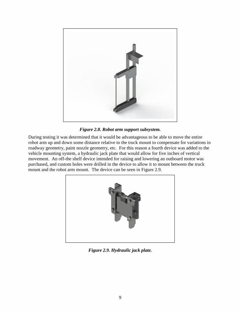
Figure 2.8. Robot arm support subsystem. During testing it was determined that it would be advantageous to be able to move the entire robot arm up and down some distance relative to the truck mount to compensate for variations in roadway geometry, paint nozzle geometry, etc. For this reason a fourth device was added to the vehicle mounting system, a hydraulic jack plate that would allow for five inches of vertical movement. An off-the shelf device intended for raising and lowering an outboard motor was purchased, and custom holes were drilled in the device to allow it to mount between the truck mount and the robot arm mount. The device can be seen in Figure 2.9.
Figure 2.9. Hydraulic jack plate.

10
2.3 Motion Control System The motion control system relies on servo motors working through right-angle gearboxes to drive the moving parts of the robot arm. The motors and gearboxes were sized based on the expected loads given the desired speeds, accelerations, and decelerations for the arm joints. These parameters were determined based on the target painting speed of 12 in. per second that was determined during the prototype project. The first powered joint utilizes a larger gearbox due to the greater weight of the two-segment load that it moves. The gearboxes selected for the first and second joints each provide a 50:1 reduction, and each gearbox drives the arm via a belt drive that provides an additional 3:1 reduction. The resulting overall reduction is 150:1, giving the servo motors a great mechanical advantage when driving the arm segments. Figure 2.10 shows the details of the drive system for each of the first two joints. The third powered joint directly drives the paint head as previously discussed, and it employs a 100:1 gear reduction.
Figure 2.10. Drive system design details. The mechanical design of the arm is referred to as a SCARA configuration [4]. The first drive motor is designated as the X-axis, and is often referred to as the shoulder joint. The second drive motor is designated as the Y-axis and is often referred to as the elbow joint. The third drive motor is designated as the Z-axis and is often referred to as the wrist joint. The first two joints are responsible for controlling the position of the paint head in X-Y space, while the third joint is responsible for controlling the orientation (rotation) of the paint head. Since the paint head spray tip produces a fan shaped spray pattern, proper control of rotation is important to the final appearance of the painted pattern.
The servo motors were initially controlled with a Galil DMC-2143 motion controller working through an AMP-20540 four-channel servo amplifier (one channel is unused). The motion control board and servo amplifier were both re-used from the prototype (trailer) project. Later in the development of the robot arm it became necessary to upgrade the control system to a more capable unit, and it was replaced with a Galil DMC-4040 motion controller working through an AMP 43240 four-channel servo amplifier (see Figure 2.11). This control system provided a significant improvement in computational speed and a significant increase in servo drive power.

11
Both of these enhancements were critical in improving the mechanical performance of the robot arm.
The control board, servo amplifier, and related electrical components were mounted in a control box. The control box will be located in the cab of the truck for protection, and to provide the interface for the laptop computer used for the operator interface. The control box can be seen in Figure 2.12.
Figure 2.12. Robot control box.
Figure 2.11. Galil motion control board with built-in and servo amplifier. (http://www.galil.com/motion-controllers/multi-axis/dmc-40x0)

12
2.4 Mobile Power Supply The servo controller and amplifier require a 48 VDC power supply, some of the controls require a 24 VDC power supply, the robot arm jack plate requires 12 VDC, and the paint pump, air compressor, and laptop computer require 120 VAC. In order to make the robot completely mobile, a battery-powered rechargeable power supply was designed and built. The power is provided by a group of four 12-volt deep cycle batteries which directly provide the 12, 24, and 48 volt levels required by the control system. An inverter-charger was also purchased that charges the batteries when the robot is in the garage, and generates 120 VAC from the 48 VDC battery supply when the robot is on the road. The inverter-charger and all 120 VAC components are mounted in one weatherproof box, and the batteries and other DC components are mounted in a separate weather proof box. The mobile power supply is shown in Figure 2.13.
Inverter/Charger Battery Box
Figure 2.13. Mobile power supply. The electrical wiring for the servo motors, encoders, sensors, and actuators was run through the hollow portion of each robot arm segment, and flexible conduit was used to route the wiring around the joints to provide an adequate range of motion for the arm. The flexible conduits were terminated on the robot arm junction box. Figure 2.14 shows the configuration of the wireways for the robot arm. There is a large umbilical that carries all power and signals between the robot arm junction box and the control box.
13
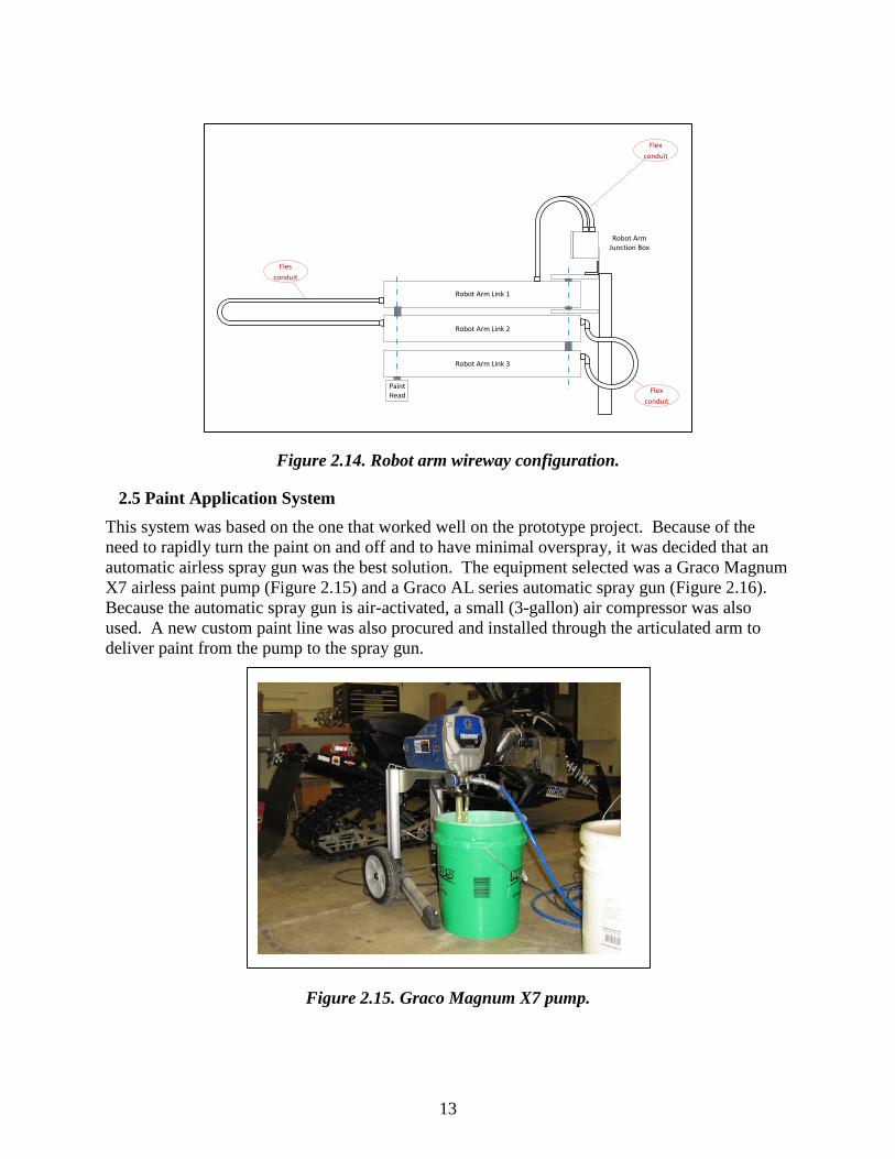
Figure 2.14. Robot arm wireway configuration.
2.5 Paint Application System This system was based on the one that worked well on the prototype project. Because of the need to rapidly turn the paint on and off and to have minimal overspray, it was decided that an automatic airless spray gun was the best solution. The equipment selected was a Graco Magnum X7 airless paint pump (Figure 2.15) and a Graco AL series automatic spray gun (Figure 2.16). Because the automatic spray gun is air-activated, a small (3-gallon) air compressor was also used. A new custom paint line was also procured and installed through the articulated arm to deliver paint from the pump to the spray gun.
Figure 2.15. Graco Magnum X7 pump.
Robot Arm Link 1
Robot Arm Link 2
Robot Arm Link 3
PaintHead
Flex conduit
Flex conduit
Fles conduit
Robot ArmJunction Box

14
Figure 2.16. Graco AL airless spray gun. One reason that the Graco spray gun was chosen was its use of the RAC5 spray nozzle system. This system allows the operator to reverse the direction of the spray tip to quickly clear clogs caused by small suspended solids in the paint. It also allows spray tips to be changed quickly with no tools required. The paint tip used for the final testing was a RAC5-113 tip. Finally, the system incorporates a protective guard which prevents personnel from coming into close contact with the spray tip. This prevents accidental paint injection, which is possible with the pressures used in airless spray systems. The Graco Magnum X7 paint pump used on this project is capable of developing up to 3000 p.s.i. of working pressure.
2.6 Reflective Bead Application System It was originally intended to supply an application system for reflective beads that was similar to the paint application system. That is, it would be integrated into the robot arm, and automatically turned on and off. It became apparent during the construction of the robot arm that it would not be possible to incorporate the large hose used for reflective beads, and the lack of flexibility of this hose would hinder the movement of the arm. Further development of the automated reflective bead application system was suspended at that point. This means that the operator would have to get out of the truck and apply the beads manually once the painting is complete, as is currently done. An addendum to the contract was process that allowed the funds left over from the bead application system to be applied toward the controller upgrade and software upgrade.
2.7 Operator Interface A software package called “Think & Do Live!” was used to provide a platform for developing the user interface. This software has drivers that seamlessly interface with the Galil motion control system so development time was minimized. Version 5 of this software was first used, as it was re-used from the prototype (trailer) project. This software operated on the Windows XP operating system which has become obsolete, so a new version (8.1) of the software was

15
purchased as part of the controller upgrade addendum. This new version allowed the project to be moved to a modern Windows 7 laptop.
An operator interface was developed using this software to allow a person to easily control the robotic painting device (see Figure 2.17). The interface is based on a laptop computer and communicates to the motion control system via Ethernet. The interface allows an operator to do the following:
1. Extend the arm to the deployed position 2. Choose a pattern to paint 3. Execute the painting operation 4. Monitor the position of the robot arm during execution via numerical data and an
animation of the arm 5. Monitor the painting process via messages from the controller 6. Return the arm to the storage position
2.8 Painter program development The majority of time on the operator interface task was spent on developing the painting programs themselves. The Galil motion controller uses the DMC (Direct Motion Control) language and that is what was used to develop the motion programs. Programs were first developed to paint the outlines of standard MnDOT pavement markings, and then to paint words. These programs were tested in dry runs where paint was not actually applied, and then in wet runs where the patterns were painted on textured paper. This became a very time-consuming iterative process where motion parameters and other program details were changed between runs to improve the quality of painting. It soon became apparent that “filling in” the symbol outlines with the articulated robot arm would be a messy and imperfect process, as the arm is capable of painting 4-inch wide stripes and those would have to be used repeatedly to perform the filling in, resulting in considerable overlap and excess paint usage. It also became obvious that the standard outlines of turn arrows
Figure 2.17. Operator interface.

16
used by MnDOT had some geometry that was difficult to reproduce with the robot painter. As a result of these two difficulties the symbols were modified in two ways: the outlines were altered slightly to make them easier to paint with the robot, and the filling in was done using hash lines rather than solid fill. These hash lines were placed strategically into each symbol to increase the directional indication provide by the symbol. In the end, programs for the following symbols and words were developed and tested.
1. Standard MnDOT outlines a. Left turn arrow (72” W x 96” H) b. Right turn arrow (72” W x 96” H) c. Straight arrow (42” W x 110” H)
2. Modified outlines with hash-line fill a. Left turn arrow (72” W x 96” H) b. Right turn arrow (72” W x 96” H) c. Straight arrow (44” W x 110” H)
3. Words (48” high) a. AHEAD b. SLOW c. STOP d. YIELD
Combination arrows (left + straight and right + straight) were attempted, but it was impossible to fit them into the robot workspace. If combo arrows need to be painted they will have to be done using two separate programs, with the truck moving between programs.
Arm Stored Arm Deployed
Figure 2.18. Robot assembled for indoor testing.
2.9 Final Assembly The final assembly task occurred in two phases. First, the robot arm was mounted indoors so that it could be thoroughly tested under controlled conditions. All of the mechanical and electrical components were assembled and interconnected into a functional robotic system (Figure 2.18). The system was extensively tested to demonstrate that all systems were working properly, and to characterize the the mechanical and electrical behavior of the device. This testing became very time consuming and in the end helped to determine the parameters like

17
velocity and acceleration that should be used for the joints in the arm to achieve smooth motion. It also helped to determine the gain parameters used internally by the motion control system, which are dependent upon the mechanical structure and weight of each robot arm segment. The second phase of final assembly occurred when indoor testing was complete. The robot arm was removed from the indoor mount and placed on a pallet for transport to the assembly area. The truck was moved from the MnDOT garage to UMD where it was parked near the Civil Engineering loading dock. The mounting bracket was installed on the truck, followed by the hydraulic jack plate. The robot was then lifted using an overhead crane and mounted to the jack plate. Figure 2.19 shows the robot arm after installation on the truck. The auxiliary equipment (battery box, inverter/charger, air compressor, and paint pump) were placed on the flat bead of the truck and fastened down (Figure 2.20). Once the robot and auxiliary equipment were mechanically mounted to the truck the electrical connections were made. The control box and laptop were installed in the cab and cables were run from the robot into the cab to connect those. Cables and hoses were also routed to the truck bed as needed to connect the auxiliary equipment to the robot. All cables and hoses were protected by plastic sleeves, routed safely, and fastened securely to the truck. Once final assembly was complete the robot and auxiliary equipment were functionally tested to assure that they were operating properly (Figure 2.21).
Figure 2.19. Robot arm mounted to truck.

18
Figure 2.20. Truck bed with auxiliary equipment.
Figure 2.21. Truck-mounted robot arm deployed for testing.

19
2.10 Field Testing Testing also occurred in two phases. Once the device was mounted indoors it was extensively tested under controlled conditions. In addition to the electrical and mechanical testing described previously, all of the software programming was also tested indoors prior to final assembly. Tests were then run to determine the optimal values for several parameters, including air actuation pressure, paint pressure, painting speed, and paint coverage. Finally, all of the motion programs were tested to demonstrate the capabilities of the machine to paint letters and symbols on the roadway. The painting tests were first done with water, then with standard latex pavement marking paint. The indoor painting tests were done on heavy textured paper to simulate painting on pavement. The second phase of field testing occurred once the robot painter was mounted on the MnDOT painting truck. The robot was mounted on the truck in August of 2015 and the truck was transferred to the MnDOT sign shop in Pike Lake. An outdoor demonstration and test was conducted on October 13, 2015. The robot was used to attempt to paint multiple markings and a word. The robot performed as expected, but the paint delivery system did not work as planned. The weather was cold and windy (below 40 degrees F. at test time) and the paint became very viscous at the low temperature. The paint nozzle repeatedly plugged and the spray head would not function properly at the low temperature. The MnDOT personnel present at the test stated that the trucks they use to paint in low temperatures have a paint heating system that keeps the paint at 80 to 90 degrees F. and this is obviously necessary. In the end two poor markings were produced with sputtering paint, and other marking were produced using water to demonstrate the motion of the robot arm. The arm deployed, went through the proper painting procedure, and stored itself successfully each time.

20
CHAPTER 3: RESULTS
3.1 System Test Results Several tests were performed to determine the maximum or optimal values for mechanical and electrical parameters in the system. The results of these tests were as follows:
• Maximum paintable area 156 in. x 116 in. (4.0 m x 3.0 m) • Optimal painting speed 12 in./sec. (300 mm/sec) • Optimal painting width 4 in. (100 mm) • Optimal paint pressure 2500 psi (17.5 MPa) • Actuation air pressure range 80-100 psi (.56-.70 MPa)
3.2 Painting Results All of the motion programs were first tested indoors on textured paper to demonstrate the capabilities of the machine to paint letters and symbols on the roadway. The results of some of the tests are shown in Figure 3.1. The outdoor test did not produce any useable results.

21
Words
Left Turn Arrow
Straight Arrow Right Turn Arrow
Figure 3.1. Painting Results.
22
CHAPTER 4: CONCLUSIONS
4.1 Summary of Conclusions A vehicle-mounted, long-reach articulated robot arm was designed and built for the purpose of painting symbols and messages on a roadway. The robot is unique in that it is completely mobile and self-contained, including a mobile robot controller, air compressor, and paint delivery system all powered by a rechargeable 48 VDC mobile power supply. The mechanical and electrical aspects of the robot were extensively tested. An operator interface was developed for the robot and painting programs were developed to paint several symbols and messages on the roadway.
This device has the potential to completely change the way in which markings are painted on roadways. The device has demonstrated the ability to paint roadway markings using an articulated robot arm mounted on the front of a vehicle and has helped to determine many of the design parameters necessary to develop a commercially viable unit. The device can be controlled from a laptop computer in the cab of the vehicle by a single operator. Expected benefits of the deployment of such a device include improved operator safety, improved productivity, and improved flexibility in roadway marking operations.
Another important finding of this research is that the traditional markings used by MnDOT are not ideal for robot application. Robotic painting can be better accommodated by altering the outlines of the markings somewhat, and by using directional hash lines to fill in the symbols rather than solid paint. These machine-made markings are faster to apply and use less paint, and in the end, may be more effective for motorists than the traditional markings.
4.2 Shortcomings Since this is the first device of its kind it naturally has some shortcomings. The first problem discovered during testing was that the deployment system, which is based on a pneumatic cylinder, is not reliable enough. The system behaves differently based on air pressure, ambient air temperature, and roadway levelness. These variables affect the deployment and storage movements so that they are sometimes too slow and sometimes too fast and violent. The pneumatic cylinder should be replaced with some sort of motorized jack screw to make deployment and storage more reliable. Also, slight flexibility in the mounting system and arm joint drives leads to some wobbliness during motion. This is particularly obvious when rapid acceleration or deceleration is performed at the limits of the workspace, when the arm is extended nearly three meters. To minimize this problem the acceleration and deceleration rates of the robot arm were reduced to very mild values. The consequence if this is one of the other shortcomings of the arm, paint buildup during acceleration and deceleration. The painter applies markings by using a series of linear and circular arc segments. Each time a segment begins and ends there is a period of acceleration or deceleration. During this period the arm velocity is less than what is desired and the paint buildup is excessive. To mitigate this, a delay was implemented before turning on the paint during acceleration, but that measure was not completely effective. The initial workspace proposed for the vehicle mounted painter was rectangular at 12 ft. wide and 8 ft. high. This was a result of the original gantry-style design concept. The articulated arm

23
actually implemented resulted in a somewhat larger working area, but it is still not enough to paint the larger makings, particularly combination arrows and railroad crossings. To paint such marking would involve running two separate painting programs and moving the truck between programs and alignment issues would be anticipated. Another shortcoming is a result of a technical detail in the controller. Performing robot motion with a Galil controller requires the use of either the Linear Interpolation (LI) mode or a different mode called Contour Mode (CM). The painter currently uses the Linear Interpolation mode as it is computationally simpler than the Contour Mode. The original controller that was used had a slower computation rate and it was felt that the LI mode was best for real-time motion control. The drawback of the LI mode is that it requires the motion to be divided into linear and circular arc segments, and the velocity is only approximately constant during motion. This leads to some unevenness during painting. The new controller installed during the upgrade is fully ten times faster than the original, so Contour Mode motion would be possible. With this mode velocity can be held exactly constant over virtually any path configuration, and the number of segments needed for each shape could be somewhat reduced (e.g. a line-arc-line combination could be done as a single segment). Converting the motion programs to contour mode would mean rewriting all of them, a time consuming task. The result, however, would likely be much higher quality painting. The paint delivery system would also have to be improved to enable heavy use in various weather conditions. Although the system worked well in indoor testing, it was not capable of delivering the paint reliably outdoors in low temperature. The truck used was the final shortcoming. The tuck was a cab-over design which requires that the cab be tilted forward to access the engine for routine maintenance checks like belt condition and fluid levels. When the robot is mounted on the front of the truck, tilting the cab forward becomes impossible. It is strongly recommended that a standard pickup truck be used in the future to eliminate this problem.

24
REFERENCES
1. R. G. Rosandich, " Improve the safety and efficiency of roadway maintenance phase I: Developing a Robotic Roadway Message Painter Prototype,” Final Report, Intelligent Transportation Systems Institute, Center for Transportation Studies, University of Minnesota, May 2012.
2. Advanced Highway Maintenance and Construction Technology Research Center, University of California Davis (Internet), Stenciling Machine and General Purpose Sign Painting System, (Accessed 10/15/2007), http://www.ahmct.ucdavis.edu/index.php?title=OtherMarkersSigns
3. D. Hong, W. Lee, B. Chu, and T. Kim, “Gantry Robot with Extended Workspace for Pavement Sign Painting Operations,” Journal of Mechanical Science and Technology, Vol. 19, no. 6, 1268-1279 (2005).
4. S. B. Niku, An Introduction to Robotics, Prentice Hall, Upper Saddle River, N. J., p. 11 (2001).

APPENDIX A
Standard Operating Procedure

A-1
Robot Painter Standard Operating Procedure 1) Computer access
a) User name: MnDOT_2012 b) Password: Robot_2015
2) Operation a) Pull the pin from the robot arm retaining rod and remove the rod. b) Pull the pin from the robot arm support foot and drop the foot. c) Adjust the height of the robot using the Up/Down toggle switch located on the robot arm. d) Turn on the air compressor in the truck bed and pressurize the air system to 85 psi. e) Turn on the 48 VDC rotary switch on the control box in the cab. f) Turn on the 24 VDC toggle switch on the control box in the cab. g) Plug the software USB key into the laptop, and turn the laptop on. h) Connect the laptop to the controller using the Ethernet crossover cable. i) Turn the laptop on and run the Think and Do Live software. j) Load the robot control project and execute it. This should open the operator control screen for the
robot. k) Install the desired paint nozzle on the robot paint gun. l) Put a pail of paint under the paint pump in the truck bed and prime and pressurize the paint
system (see Graco Magnum X7 Operation manual pp. 10-11). The paint gun can be manually operated through the operator screen if necessary.
m) Press the “Deploy Arm” button on the operator screen and wait for the arm to deploy. n) Select a program from the drop-down list and press the “Run Program” button. Wait for the
program to be completed. o) When painting is complete press the “Store Arm” button on the operator screen and wait for the
arm to store itself. p) Lift the robot arm support foot and install the retaining pin. q) Install the robot arm retaining rod and the associated pin. r) Turn off the 24 VDC toggle switch on the control box in the cab. s) Turn off the 48 VDC rotary switch on the control box in the cab. t) Shut down the Think and Do Live software and turn off the laptop computer. u) Turn off the air compressor in the truck bed. v) Shut down the paint pump in the truck bed and remove the paint pail.
3) Calibration a) Once the arm is prepared for operation and deployed as described above it can be calibrated. b) Run the “Fold Arm” program from the drop-down list. The arm will fold under itself. c) Use the X, Y, and Z plus and minus buttons on the operator screen to move the arm in small
increments until the arm is aligned perfectly under itself, and the paint head is aligned with the arm.
d) Once the alignment is satisfactory press the “Calibrate” button on the operator screen. e) Run the “Unfold Arm” program from the drop-down list. This will return the arm to the deployed
position and calibration is complete.

A-2
4) Storage a) The robot arm should be stored indoors b) The paint system should be flushed completely and filled with water after each use (see Graco
Magnum X7 Operation manual p. 17). If the unit will not be used for more than two days, fill the pump with Graco Pump Armor (see Graco Magnum X7 Operation manual p. 22).
c) The robot power supply inverter/charger needs to be kept plugged in to a live outlet (long extension cord on truck). This will keep the batteries in a good state of charge. If the robot is not plugged in for a long period of time the batteries will fall below a critical charge level and the inverter/charger will refuse to start. If this happens each battery must be individually charged using a conventional charger until the system voltage is high enough to allow the inverter/charger to start (see Tripp-Lite APS Powerverter Operator’s Manual p. 13).

APPENDIX B
Graco Magnum X7 Operation Manual

Operation
X5™, X7™, ProX7™ & ProX9™ Airless Sprayers
312001REN
- For portable spray applications of architectural paints and coatings -
X5 & X7 Models ONLY: Use water-based or min-eral spirit-type materials only. Do not use materi-als having flash points lower than 70° F (21° C). This includes, but is not limited to, acetone, xylene, toluene, or naptha. For more information about your material, request MSDS from distribu-tor or retailer.
Models 262800, 262805, 261815, 261820
See page 2 for model and series information including dispense rate, recommended hose length, guns, and maximum working pressure.
IMPORTANT SAFETY INSTRUCTIONS.Read all warnings and instructions in this manual. Save these instructions.
MAGNUM X5Model: 262800
ti11304a
Series D
MAGNUM X7Model: 262805
ti11305a
Series C
MAGNUM ProX7Model: 261815
ti9369b
Series B
MAGNUM ProX9Model: 261820Series B
ti16976a
The manual provided with this sprayer contains English and Español.
Visit our website; http://MAGNUM.Graco.com
B-1

Specifications
2 312001R
SpecificationsThis equipment is not intended for use with flammable or combustible materials used in places such as cabinet shops or other “factory”, or fixed locations. If you intend to use this equipment in this type of appli-cation, you must comply with NFPA 33 and OSHA requirements for the use of flammable and combustible materials.
Model Name SeriesDispense Rate gpm
(lpm)
Hose Length and Diameter
Gun Model
Maximum Working Pressure
PSI MPa bar
MAGNUM X5 D0.27 gpm (1.02 lpm)
1/4 in. x 25 ft (6.4 mm x 7.5 m)
SG2 3000 21 207
MAGNUM X7 C0.31 gpm (1.17 lpm)
1/4 in. x 25 ft (6.4 mm x 7.5 m)
SG2 3000 21 207
MAGNUM ProX7 B0.34 gpm(1.29 lpm)
1/4 in. X 50 ft (6.4 mm x 15 m)
SG3 3000 21 207
MAGNUM ProX9 B0.38 gpm(1.44 lpm)
1/4 in. X 50 ft (6.4 mm x 15 m)
SG3 3000 21 207
B-2

Warnings
312001R 3
WarningsThe following warnings are for the setup, use, grounding, maintenance and repair of this equipment. The exclamation point symbol alerts you to a general warning and the hazard symbol refers to procedure-spe-cific risks. Refer back to these warnings. Additional, product-specific warnings may be found throughout the body of this manual where applicable.
WARNINGWARNINGWARNINGWARNINGGROUNDINGThis product must be grounded. In the event of an electrical short circuit, grounding reduces the risk of electric shock by providing an escape wire for the electric current. This product is equipped with a cord having a grounding wire with an appropriate grounding plug. The plug must be plugged into an outlet that is properly installed and grounded in accordance with all local codes and ordinances.
• Improper installation of the grounding plug is able to result in a risk of electric shock.• When repair or replacement of the cord or plug is required, do not connect the grounding
wire to either flat blade terminal.• The wire with insulation having an outer surface that is green with or without yellow stripes is
the grounding wire.• Check with a qualified electrician or serviceman when the grounding instructions are not
completely understood, or when in doubt as to whether the product is properly grounded.• Do not modify the plug provided; if it does not fit the outlet, have the proper outlet installed
by a qualified electrician.• This product is for use on a nominal 120V circuit and has a grounding plug similar to the
plug illustrated in the figure below.
• Only connect the product to an outlet having the same configuration as the plug.• Do not use an adapter with this product.
Extension Cords:• Use only a 3-wire extension cord that has a 3-blade grounding plug and a 3-slot receptacle
that accepts the plug on the product.• Make sure your extension cord is not damaged. If an extension cord is necessary, use 12
AWG (2.5 mm2) minimum to carry the current that the product draws.• An undersized cord results in a drop in line voltage and loss of power and overheating.
ti9164a
B-3

Warnings
4 312001R
FIRE AND EXPLOSION HAZARD Flammable fumes, such as solvent and paint fumes, in work area can ignite or explode. To help prevent fire and explosion:• Do not spray flammable or combustible materials near an open flame or sources of ignition
such as cigarettes, motors, and electrical equipment. For X5 and X7 models: only usewater-based or mineral spirit-type materials with a flash point greater than 70° F (21° C).
• Paint or solvent flowing through the equipment is able to result in static electricity. Staticelectricity creates a risk of fire or explosion in the presence of paint or solvent fumes. Allparts of the spray system, including the pump, hose assembly, spray gun, and objects inand around the spray area shall be properly grounded to protect against static dischargeand sparks. Use Graco conductive or grounded high-pressure airless paint sprayer hoses.
• Verify that all containers and collection systems are grounded to prevent static discharge.• Connect to a grounded outlet and use grounded extensions cords. Do not use a 3-to-2
adapter.• Do not use a paint or a solvent containing halogenated hydrocarbons.• Keep spray area well-ventilated. Keep a good supply of fresh air moving through the area.
Keep pump assembly in a well ventilated area. Do not spray pump assembly.• Do not smoke in the spray area.• Do not operate light switches, engines, or similar spark producing products in the spray
area.• Keep area clean and free of paint or solvent containers, rags, and other flammable materi-
als.• Know the contents of the paints and solvents being sprayed. Read all Material Safety Data
Sheets (MSDS) and container labels provided with the paints and solvents. Follow the paintand solvents manufacturer’s safety instructions.
• Fire extinguisher equipment shall be present and working.• Sprayer generates sparks. When flammable liquid is used in or near the sprayer or for flush-
ing or cleaning, keep sprayer at least 20 feet (6 m) away from explosive vapors.
WARNINGWARNINGWARNINGWARNING
B-4

Warnings
312001R 5
SKIN INJECTION HAZARD • Do not aim the gun at, or spray any person or animal.• Keep hands and other body parts away from the discharge. For example, do not try to stop
leaks with any part of the body.• Always use the nozzle tip guard. Do not spray without nozzle tip guard in place.• Use Graco nozzle tips.• Use caution when cleaning and changing nozzle tips. In the case where the nozzle tip clogs
while spraying, follow the Pressure Relief Procedure for turning off the unit and relievingthe pressure before removing the nozzle tip to clean.
• Do not leave the unit energized or under pressure while unattended. When the unit is not inuse, turn off the unit and follow the Pressure Relief Procedure for turning off the unit.
• High-pressure spray is able to inject toxins into the body and cause serious bodily injury. Inthe event that injection occurs, get immediate surgical treatment.
• Check hoses and parts for signs of damage. Replace any damaged hoses or parts.• This system is capable of producing 3000 psi. Use Graco replacement parts or accessories
that are rated a minimum of 3000 psi.• Always engage the trigger lock when not spraying. Verify the trigger lock is functioning prop-
erly.• Verify that all connections are secure before operating the unit.• Know how to stop the unit and bleed pressure quickly. Be thoroughly familiar with the con-
trols.EQUIPMENT MISUSE HAZARDMisuse can cause death or serious injury.• Do not operate the unit when fatigued or under the influence of drugs or alcohol.• Do not exceed the maximum working pressure or temperature rating of the lowest rated sys-
tem component. See Technical Data in all equipment manuals.• Use fluids and solvents that are compatible with equipment wetted parts. See Technical
Data in all equipment manuals. Read fluid and solvent manufacturer’s warnings. For com-plete information about your material, request MSDS from distributor or retailer.
• Do not leave the work area while equipment is energized or under pressure.• Turn off all equipment and follow the Pressure Relief Procedure when equipment is not in
use.• Check equipment daily. Repair or replace worn or damaged parts immediately with genuine
manufacturer’s replacement parts only.• Do not alter or modify equipment. Alterations or modifications may void agency approvals
and create safety hazards.• Make sure all equipment is rated and approved for the environment in which you are using
it.• Use equipment only for its intended purpose. Call your distributor for information.• Route hoses and cables away from traffic areas, sharp edges, moving parts, and hot sur-
faces.• Do not kink or over bend hoses or use hoses to pull equipment.• Keep children and animals away from work area.• Comply with all applicable safety regulations.
WARNINGWARNINGWARNINGWARNING
B-5

Warnings
6 312001R
ELECTRIC SHOCK HAZARD This equipment must be grounded. Improper grounding, setup, or usage of the system can cause electric shock.• Turn off and disconnect power cord before servicing equipment.• Connect only to grounded electrical outlets.• Use only 3-wire extension cords.• Ensure ground prongs are intact on power and extension cords.• Do not expose to rain. Store indoorsPRESSURIZED ALUMINUM PARTS HAZARD Use of fluids that are incompatible with aluminum in pressurized equipment can cause serious chemical reaction and equipment rupture. Failure to follow this warning can result in death, serious injury, or property damage.• Do not use 1,1,1-trichloroethane, methylene chloride, other halogenated hydrocarbon sol-
vents or fluids containing such solvents.• Many other fluids may contain chemicals that can react with aluminum. Contact your mate-
rial supplier for compatibility.BURN HAZARDEquipment surfaces and fluid that’s heated can become very hot during operation. To avoid severe burns:• Do not touch hot fluid or equipment.MOVING PARTS HAZARD Moving parts can pinch or amputate fingers and other body parts.• Keep clear of moving parts.• Do not operate equipment with protective guards or covers removed.• Pressurized equipment can start without warning. Before checking, moving, or servicing
equipment, follow the Pressure Relief Procedure in this manual. Disconnect power or airsupply.
TOXIC FLUID OR FUMES HAZARD Toxic fluids or fumes can cause serious injury or death if splashed in the eyes or on skin, inhaled, or swallowed.• Read MSDS’s to know the specific hazards of the fluids you are using.• Store hazardous fluid in approved containers, and dispose of it according to applicable
guidelines.PERSONAL PROTECTIVE EQUIPMENT Wear appropriate protective equipment when in the work area to help prevent serious injury, including eye injury, hearing loss, inhalation of toxic fumes, and burns. This protective equip-ment includes but is not limited to:• Protective eyewear, and hearing protection.• Respirators, protective clothing, and gloves as recommended by the fluid and solvent manu-
facturer.
WARNINGWARNINGWARNINGWARNING
B-6

Grounding and Electric Requirements
312001R 7
Grounding and Electric Requirements
Sprayer must be grounded. Grounding reduces the risk of static and electric shock by providing an escape wire for electrical current due to static build up or in the event of a short circuit.• The 120 Vac spray-
ers require a 120 Vac, 60 Hz, 15A cir-cuit with a ground-ing receptacle.
• Never use an outletthat is not groundedor an adapter.
• Do not use the sprayer if theelectrical cord has a dam-aged ground prong.
• Only use an extension cordwith an undamaged 3-prongplug.
Recommended extension cords for use withthis sprayer:
• 50 ft (15.0 m) 14 AWG (2.1 mm2)
• 100 ft (30.0 m) 12 AWG (3.3 mm2)
Spray gun: ground through connection to a prop-erly grounded fluid hose and pump.
NOTE: Smaller gauge or longer extension cords may reduce sprayer performance.
Fluid supply container: follow local code.
Solvent pails used when flushing: follow local code. Use only conductive metal pails, placed on a grounded surface such as concrete. Do not place the pail on a nonconductive surface, such as paper or cardboard, which interrupts grounding continuity.
Grounding the metal pail: connect a ground wire to the pail by clamping one end to pail and other end to ground such as a water pipe.Maintaining grounding con-tinuity when flushing or relieving pressure: hold metal part of the spray gun firmly to the side of a grounded metal pail, then trigger the gun.
Thermal OverloadMotor has a thermal overload switch to shut itself down if overheated. If unit overheats, allow approx-imately 45 minutes for unit to cool. Once cool, switch will close and unit will restart.
ti5573a
ti5572a
To reduce risk of injury from motor starting unex-pectedly when it cools, always turn power switch OFF if motor shuts down.
ti9207a
B-7

Component Identification
8 312001R
Component IdentificationA Airless spray gun Dispenses fluid.
B Power switch Turns sprayer ON and OFF.
C Pressure control knobIncreases (clockwise) and decreases (counter-clockwise) fluid pressure in pump, hose, and spray gun.
C1 Setting IndicatorTo select function, align symbol on pressure control knob with settingindicator, page 14.
D Pump fluid outlet fitting Threaded connection for paint hose.
E InstaClean™ fluid filter(ProX Sprayers Only)
• Filters fluid coming out of pump to reduce tip plugging and improvefinish.
• Self cleans only during pressure relief.
F
ProX Power-Piston™ Pump (behind Easy Access door, not shown) (ProX Sprayers Only)
Pumps and pressurizes fluid and delivers it to paint hose.
F1Easy Access door(ProX Sprayers Only)
Easy Access door permits quick access to outlet valve. To remove door, insert flat blade of screwdriver into slot on the bottom of the door (as shown on page, 7).
G Suction tube Draws fluid from paint pail into pump.
H Prime tube (with diffuser) Drains fluid in system during priming and pressure relief.
J Prime/Spray valve
• In PRIME position (pointing down) directs fluid to prime tube.• In SPRAY position (pointing forward) directs pressurized fluid to paint
hose.• Automatically relieves system pressure in overpressure situations.
K Autoprime Automatically taps the inlet ball when you turn the sprayer on.
L Inlet screen Prevents debris from entering pump.
M Paint hose Transports high-pressure fluid from pump to spray gun.
Q Tip guard Reduces risk of fluid injection injury.
R Reversible spray tip• Atomizes fluid being sprayed, forms spray pattern and controls fluid flow
according to hole size.• Reverse unclogs plugged tips without disassembly.
SGun trigger safety lever (page 10)
Prevents accidental triggering of spray gun.
T Gun fluid inlet fitting Threaded connection for paint hose.
U Power Flush attachment Connects garden hose to suction tube for power flushing water-base fluids.
V Gun fluid filter Filters fluid entering spray gun to reduce tip clogs.
W Hose wrap Rack Stows paint hose. (X7, ProX7, and ProX9 only)
XPail hanger(X7, Prox7, and ProX9)
For transporting pail by its handle.
B-8

Component Identification
312001R 9
J
ED
X
B
K
W
F
C
G
L
H
Q
R
A
S
T
ti9669a
ti9667aM
ti9368b
C1
ti9346a
ti9670a
F1
U
ti9724a
ti16978a
V (SG2/SG3)
B-9

Operation
10 312001R
Operation
Trigger LockAlways engage the trigger lock when you stop spraying to prevent the gun from being triggered accidentally by hand or if dropped or bumped.
Pressure Relief ProcedureFollow this Pressure Relief Procedure whenever you stop spraying and before cleaning, checking, servicing, or transporting equipment.
1. Turn power switch OFF and unplugpower cord.
2. Turn Prime/Spray valve toPRIME to relieve pressure.
3. Hold gun firmly to side ofpail. Trigger the gun torelieve pressure.
4. Engage trigger lock.
NOTE: Leave Prime/Spray valve in the PRIME position until you are ready to spray again.
If you suspect the spray tip or hose is clogged or that pressure has not been fully relieved after fol-lowing the steps above, VERY SLOWLY loosen tip guard retaining nut or hose end coupling to relieve pressure gradually, then loosen completely. Clear hose or tip obstruction. Read Unclogging Spray Tip, page 14.
NOTE: To select function, align symbol on pressure control knob with setting indicator on sprayer.
ti8908a
Trigger Locked Trigger Unlocked
ti8909a
ti2810a
ti9346a
ti9207a
ti8908a
Pressure Control Knob Settings
High Pressure Spray
Low Pressure Spray
Prime/ Clean
Rolling
ti5597a
B-10

Setup
312001R 11
Setup
1. Unscrew tip and guardassembly from gun.
2. Uncoil hose and connectone end to gun. Use twowrenches to tightensecurely
3. Connect otherend of hose tosprayer.
NOTE: If hose is already connected, make sure connections are tight.
4. Turn OFF power switch.
5. Turn Pressure ControlKnob all the way left(counter-clockwise) tominimum pressure.
Prime and Flush Storage FluidNOTE: To spray lacquers with the ProX7 or ProX9, you must purchase lacquer conversion kit 256212, and follow priming procedure for oil-based materi-als. The X5 and X7 units are not intended for lac-quers.
Before you use your sprayer for the first time or be-gin a new spraying project, you need to prime thesprayer and flush the storage fluid out of the spray-er.
Oil- or Water-based Materials• When spraying water-based materials, flush
the system thoroughly with water.
• When spraying oil-based materials, flush thesystem thoroughly with mineral spirits or com-patible, oil-based flushing solvent.
• To spray water-based materials after spray-ing oil-based materials, flush the system thor-oughly with water first. The water flowing out ofprime tube should be clear and solvent-freebefore you begin spraying the water-basedmaterial.
• To spray oil-based materials after sprayingwater-based materials, flush the system thor-oughly with mineral spirits or a compatibleoil-based flushing solvent first. The solventflowing out of the prime tube should not containany water.
• When flushing with solvents, ground pail andgun. Read Grounding and Electric Require-ments, page 7.
• To avoid fluid splashing back on your skin orinto your eyes, always aim gun at inside wall ofpail.
ti9714a
ti9681a
ti9674b
(ProX7 & ProX9)
ti11456a
(X5 & X7)
ti2810a
ti9344a
B-11

Setup
12 312001R
1. Make sure the power switch isOFF and the sprayer isunplugged.
2. Separate prime tube (smaller)from suction tube (larger).
3. Place prime tube in wastepail.
4. Submerge suction tube inwater or flushing solvent.
5. Turn Prime/Spray Valve toPRIME.
6. Plug sprayer in a grounded outlet.
7. Turn power switch ON.
8. Align setting indicator withPrime/Clean setting onPressure Control knob untilpump starts, page 10.
9. When sprayer starts pumping, flushing solventand air bubbles will be purged from system.
Allow fluid to flow out of prime tube, into waste pail, for 30 to 60 seconds.
10. Turn power switch OFF.
11. Transfer suction tube topaint pail and submergesuction tube in paint.
12. Turn power switch ON.
13. When you see paint coming outof prime tube:
a. Point gun into waste pail.
b. Unlock gun trigger lock.
c. Pull and hold gun trigger.
d. Turn Prime/Spray valve toSPRAY.
NOTE: Some fluids may prime faster if the Power Switch is momentarily turned off so the pump can slow and stop. Repeat several times if necessary.
14. Continue to trigger gun into waste pail until yousee only paint coming out of gun.
15. Release trigger. Engage triggerlock.
16. Transfer prime tube to paint pailand clip prime tube to suctiontube.
NOTE: Motor stopping indicates pump and hose are primed with paint. If motor continues to run the sprayer is not properly primed. To reprime, turn Prime/Spray valve to PRIME and repeat step 12.
ti2810a
ti2039a
ti9652a
ti9651a
ti9346a
ti5580a
ti9718a
ti2810a
ti9653a
ti9345a
ti8909a
ti8908a
B-12

Setup
312001R 13
Install Tip and Guard on Gun
1. Engage trigger lock.
2. Verify tip and guard parts are assembled inorder shown.
3. Screw tip and guard assemblyon gun. Tighten retaining nut.
Spraying TechniquesPreventing Excessive Tip Wear
• Spray should be atomized (evenly distributed,no gaps at edges). Start at low pressure set-ting, increase pressure a little at a time until yousee a good spray pattern, without tails.
• Spray at lowest pressure that atomizes paint.
• If maximum sprayer pressure is not enough fora good spray pattern, tip is too worn. SeeReversible Spray Tip Selection Chart, page 16.
NOTE: If tails persist when spraying at the highest pressure, a smaller tip is needed or the material may need to be thinned.
Adjust Spray Pressure
This sprayer is set up for most airless spraying applications. Details on tip selection, tip wear, coat thickness, etc. are provided on page 15.
NOTE: Motor only runs when gun is triggered. Sprayer is designed to stop pumping when gun trigger is released.
Align setting indicator with function symbol on Pressure Control knob, page 10.
• Turning knob to right (clockwise), increasespressure at gun.
• Turning it left (counter-clockwise), decreasespressure.
• General spraying instructions are provided inGetting Started with Basic Spraying Tech-niques section of this manual, page 17.
ti8908a
retaining nut black rubber gasket and
guard tipti8911a
metal seat
Use tip to align seat Tip must be pushedall the way into guardin guard
ti9574ati5606a
ti9713a
ti5592a
tails-gapsat edges
pressure
goodspray pattern
too low
B-13

Setup
14 312001R
Getting StartedUse a piece of scrap cardboard to practice these basic spraying techniques before you begin spray-ing the surface.
• Hold gun 12 in. (30 cm) from surface and aimstraight at surface. Tilting gun to direct sprayangle causes an uneven finish.
• Flex wrist to keep gun pointed straight. Fanninggun to direct spray at angle causes uneven fin-ish.
Triggering GunPull trigger after starting stroke. Release trigger before end of stroke. Gun must be moving when trigger is pulled and released.
Aiming GunAim tip of gun at bottom edge of previous stroke, overlapping each stroke by half.
Unclogging Spray Tip
To avoid fluid splashback:• Never pull gun trigger when arrow-shaped han-
dle is between SPRAY and UNCLOG positions.
• Tip must be pushed all the way into guard.
1. To UNCLOG tip obstruction,engage trigger lock.
2. Point arrow-shapedhandle backward toUNCLOG position.
3. Aim gun at piece ofscrap or cardboard.
4. Unlock trigger lock. Pull trig-ger to clear clog.
5. When obstruction iscleared, engage triggerlock and rotatearrow-shaped handleback to SPRAY position.
Point the arrow-shaped handle on the spray tip forward to SPRAY and backward to UNCLOG obstructions.
12 in.(30 cm)
evenfinish
thick
thin
unevenfinish ti5585a
even finish thin thick thin
ti2036a
ti2037a
ti2038a
ti8908a
ti9048a
ti8909a
ti9049a
B-14

Setup
312001R 15
Tip SelectionSelecting Tip Hole Size
Tips come in a variety of hole sizes for spraying a range of fluids. Your sprayer includes an 0.015 in (0.38 mm) tip for use in most spraying applications. Use the following table to determine the range of recommended tip hole sizes for each fluid type. If you need a tip other than the one supplied, see the Reversible Tip Selection Chart on page 16.
HINTS:• As you spray, the tip wears and enlarges. Start-
ing with a tip hole size smaller than the maxi-mum will allow you to spray within the ratedflow capacity of the sprayer.
• Maximum tip hole sizes supported by thesprayer:
– X5: 0.015 in. (0.38 mm)– X7: 0.017 in. (0.43 mm)– ProX7: 0.017 in. (0.43 mm)– ProX9: 0.019 in. (0.48 mm)
Choosing the Correct TipConsider coating and surface to be sprayed. Make sure you use best tip hole size for that coating and best fan width for that surface.
Tip Hole Size
Tip hole size controls flow rate - the amount of paint that comes out of the gun.HINTS:• Use larger tip hole sizes with thicker coatings
and smaller tip hole sizes with thinner coatings.
• Maximum tip hole sizes supported by sprayer:
– X5: 0.015 in. (0.38 mm)– X7: 0.017 in. (0.43 mm)– ProX7: 0.017 in. (0.43 mm)– ProX9: 0.019 in. (0.48 mm)
• Tips wear with use and need periodic replace-ment.
Fan Width
Fan width is the size of the spray pattern, which determines the area covered with each stroke. Nar-rower fans deliver a thicker coat, and wider fans deliver a thinner coat.
HINTS:• Select a fan width best suited to the surface
being sprayed.
• Wider fans allow provide better coverage onbroad, open surfaces.
• Narrower fans provide better control on small,confined surfaces.
Coatings
Tip Hole Size Stains Enamels Primers Interior Paints Exterior Paints
0.011 in. (0.28 mm) ✔
0.013 in. (0.33 mm) ✔ ✔ ✔ ✔
0.015 in. (0.38 mm) ✔ ✔ ✔ ✔
0.017 in. (0.43 mm) ✔ ✔ ✔
0.019 in. (0.48 mm) ✔
B-15

Setup
16 312001R
Understanding Tip Number
The last three digits of tip number (i.e.: 221413) contain information about hole size and fan width on surface when gun is held 12 in. (30.5 cm) from surface being sprayed.
Reversible Tip Selection Chart
Example: For an 8 to 10 in. (203 to 254 mm) fanwidth and 0.013 (0.33 mm) hole size, order Part No.221413.
First digit when doubled= approximatefan width
413 tip has 8-10 in.fan width
413 tip hasa 0.013 in.hole size
Last two digits = tip hole size in thousands of an inch
ti5559a
Tip Part No.
Fan Width 12 in. (305 mm) from
surface Hole Size
221311 6 - 8 in. (152 - 203 mm)
0.011 in. (0.28 mm)
221411 8 - 10 in. (203 - 254 mm)
0.011 in.(0.28 mm)
221313 6 - 8 in. (152 - 203 mm)
0.013 in. (0.33 mm)
221413 8 - 10 in. (203 - 254 mm)
0.013 in. (0.33 mm)
221415 8 - 10 in. (203 - 254 mm)
0.015 in. (0.38 mm)
221515 10 - 12 in. (254 - 305 mm)
0.015 in. (0.38 mm)
221417 8 - 10 in. (203 - 254 mm)
0.017 in. (0.43 mm)
221517 10 - 12 in. (254 - 305 mm)
0.017 in. (0.43 mm)
221619 12 - 14 in. (305 - 356 mm)
0.019 in. (0.48 mm)
B-16

Shutdown and Cleaning
312001R 17
Shutdown and Cleaning
Pail Flushing• For short term shutdown periods (overnight to
two days) refer to Short Term Storage, page 22.
• For flushing after spraying oil-based coatings,use compatible oil-based flushing fluid or min-eral spirits. Read Priming and Flushing StorageFluid, page 11.
• For flushing after spraying water-based coat-ings, use water. Read Priming and FlushingStorage Fluid, page 11 or Power Flush, page19.
1. Relieve pressure, page 10.
2. Remove tip and guard assembly from gun andplace in flushing fluid.
3. Lift suction tube and prime tube from paint pail.Let them drain into paint pail for a while.
4. Separate prime tube (smaller)from suction tube (larger).
5. Place empty waste andwater or solvent pailsside by side.
6. Place prime tube in wastepail.
7. Submerge suction tube inwater or flushing solvent.
8. Turn pressure control knob tothe Prime/Clean setting.
9. Turn power switch ON.
10. Flush until approximately 1/3 of the flushingfluid is emptied from the pail.
11. Turn power switch OFF.
ti2039a
ti9726a
ti9652a
ti9651a
ti9344a
ti5580a
ti2018a
B-17

Shutdown and Cleaning
18 312001R
NOTE: Step 12 is for returning paint in hose back to paint pail. One 50-ft hose holds approximately 1-quart (1-liter) of paint.
12. To preserve paint in hose:
a. Point gun into paint pail.
b. Unlock gun trigger lock.
c. Pull and hold gun trigger.
d. Turn Prime/Spray valve toSPRAY.
e. Turn power switch ON.
f. Continue to hold gun trig-ger until you see paintdiluted with flushing fluidstarting to come out ofgun.
13. While continuing to triggergun, quickly move gun toredirect spray into wastepail. Continue triggeringgun into waste pail untilflushing fluid dispensedfrom gun is relativelyclear.
14. Stop triggering gun. Engagethe trigger lock.
15. Turn prime/spray valve toPrime.
16. Turn power switch OFF.
17. Clean InstaClean Fluid Filter and gun, page 21.
18. Fill unit with Pump Armor™ storage fluid. ReadLong Term Storage, page 22.
o preserve paint in hose, trigger gun into paint pailto expel the remaining paint.
ti9345a
ti5580a
ti8909a
ti9745a
ti8908a
ti9346a
ti2018a
B-18

Shutdown and Cleaning
312001R 19
Power FlushPower flushing is a faster method of flushing. It can only be used after spraying water-based coatings.
1. Relieve pressure, page 10.
2. Remove tip and guard assembly from gun andplace in waste pail.
3. Place empty waste andpaint pails side by side.
4. Lift suction tube and prime tube from paint pail.Let them drain into paint for a while.
5. Place suction and prime tube in waste pail.
6. Turn Pressure Control knob to thePrime/Clean setting.
7. Screw power flush attachmentto garden hose. Close valve.
8. Turn on water. Open valve.Rinse paint off suction tube,prime tube and inlet screen.
9. Turn lever to close power flushattachment.
10. Unscrew inlet screen from suctiontube. Place inlet screen in wastepail.
11. Connect garden hose to suctiontube with Power Flush attachment.Leave prime tube in waste pail.
12. Turn power switch ON.
13. Open lever on PowerFlush attachment.
14. Circulate water through sprayer, into waste pail,for 20 seconds.
15. Turn power switch OFF.
ti9726a
ti9344a
ti9413a
ti9727a
ti2040a
ti2042a
ti5580a
ti2043a
ti2018a
B-19

Shutdown and Cleaning
20 312001R
NOTE: Step 16 is for returning paint in hose back to paint pail. One 50-ft (15-m) hose holds approxi-mately 1-quart (1-liter) of paint.
16. To preserve paint in hose:
a. Point gun into paint pail.
b. Unlock gun trigger lock.
c. Pull and hold gun trigger.
d. Turn Prime/Spray valve to SPRAY.
e. Turn power switch ON.
f. Continue to hold gun trigger until you see paint diluted with water starting to come out of gun.
17. While continuing to trigger gun, quickly move gun to redirect spray into waste pail. Continue triggering gun into waste pail until water coming out of gun is relatively clear.
18. Stop triggering gun. Engage trigger lock.
19. Turn prime/spray valve to Prime.
20. Turn power switch OFF.
21. Turn off garden hose. Close Power Flush attachment.
22. Unscrew Power Flush attachment from suction tube.
23. Clean InstaClean Fluid Filter and gun, page 21.
ti9345a
ti5580a
ti8909a
ti9745a
ti8908a
ti9346a
ti2810a
ti9413a
ti2047a
B-20

Shutdown and Cleaning
312001R 21
Cleaning InstaClean™ Fluid Filter (ProX Sprayers Only)The InstaClean Fluid Filter prevents particles from entering paint hose. After each use, remove and clean it to insure peak performance.
1. Relieve pressure, page10.
2.a. Disconnect airless
spray hose (a) fromsprayer
b. Unscrew outlet fitting(b).
c. Remove InstaClean Fluid Filter (c).
3. Check InstaClean Fluid Filter (c) for debris. Ifneeded, clean filter with water and a soft brush.
a. Install closed (square)end of InstaCleanFluid Filter (c) insprayer.
b. Screw outlet fitting (b)into sprayer.
4. Tighten outlet fitting andreconnect hose (a) tosprayer. Use twowrenches to tightensecurely.
Cleaning Gun • Clean gun fluid filter (d) with
water or flushing solvent and abrush every time you flush thesystem. Replace gun filter ifdamaged.
• Remove tip and guard andclean with water or flushingsolvent. A soft brush can beused to loosen and removedried on material if needed.
• Wipe paint off outside of gunusing a soft cloth moistenedwith water or flushing solvent.
a
b
c
ti9347a
c
bti9347a
a
ti9674b
ti9668a
d
ti9671a
B-21

Storage
22 312001R
StorageShort Term Storage (up to 2 days)
1. Relieve pressure, page10.
2. Leave suction tube andprime tube in paint pail.
3. Cover paint pail and hosestightly with plastic wrap.
4.a. Engage trigger lock.
b. Leave gun attached tohose.
c. If you have not alreadycleaned them, removetip and guard from gunand clean with water orflushing solvent. A softbrush can be used toloosen and removedried on material ifneeded.
d. Wipe paint off outside of gun using a softcloth moistened with water or flushing sol-vent.
Long Term Storage (more than 2 days)
Always circulate Pump Armor storage fluid through system after cleaning. Water left in sprayer will cor-rode and damage pump. Follow Shutdown and Cleaning, page 17, or Power Flush Cleaning, page 19.
1. Place suction tube inPump Armor storagefluid bottle and primetube in waste pail.
2. Turn Prime/Spray valveto PRIME.
3. Turn power switch ON.
4. Turn pressure control knobclockwise until the pumpturns on.
5. When storage fluid comesout of prime tube (5-10seconds) turn power switchOFF.
6. Turn Prime/Spray valve toSPRAY to keep storagefluid in sprayer duringstorage.
ti9353b
ti9350a
ti9671a
ti8908a
ti2057a
ti9346a
ti5580a
ti9343b
ti9345a
ti2018a
B-22

Storage
312001R 23
Stowing Sprayer
1. Screw inlet screen ontosuction tube.
2. Coil hose. Leave itconnected to sprayer.Wrap hose around hosewrap bracket.
3. Secure a plastic bag aroundsuction tube to catch anydrips.
4. Store sprayer indoors.
NOTICE• Before storing sprayer make sure all water is
drained out of sprayer and hoses.
• Do not allow water to freeze in sprayer or hose.
• Do not store sprayer under pressure.
ti9433a
ti9366b
ti5552a
B-23

Maintenance and Service
24 312001R
Maintenance and Service
Caring for SprayerKeep sprayer and all accesso-ries clean and in good working order.
To avoid overheating motor, keep vent holes in shroud clear for air flow. Do not cover sprayer while spraying.
Paint HosesCheck hose for damage every time you spray. Do not attempt to repair hose if hose jacket or fittings are damaged. Do not use hoses shorter than 25 ft (7.6 m). Wrench tighten, using two wrenches.
Tips• Always clean tips with
compatible solvent andbrush after spraying.
• Tips may requirereplacement after 15 gal-lons (57 liters) or theymay last through 60 gal-lons (227 liters) depend-ing on abrasiveness of paint.
• Do not spray with worn tip.
Pump PackingsWhen pump packings wear, paint will begin to leak down outside of pump. • Replace pump packings at
first sign of leaking or addi-tional damage could occur.
• Purchase a pump repair kitand install according toinstructions provided withkit.
• Consult a Graco/MAGNUM
authorized service center.
NOTICEProtect the internal drive parts of this sprayer from water. Openings in shroud allow cooling of mechanical parts and electronics inside. If water gets into these openings, the sprayer could mal-function or be permanently damaged.
ti3388a
ti9355b
ti2055a
ti9356a
B-24

Troubleshooting
312001R 25
TroubleshootingCheck everything in this Troubleshooting Table before you bring the sprayer to a Graco/MAGNUM authorized service center.
Problem Cause Solution
Power switch is on and sprayer is plugged in, but motor does not run, and pump does not cycle.
Pressure is set at zero pressure. Turn pressure control knob clock-wise to increase pressure setting.
Motor or control is damaged. Take sprayer to Graco/MAGNUM authorized service center.
Electric outlet is not providing power.
• Try a different outlet or plug insomething that you know isworking to test outlet.
• Reset building circuit breakeror replace fuse.
Extension cord is damaged. Replace extension cord. Read Grounding and Electric Require-ments, page 7.
Sprayer electric cord is damaged. Check for broken insulation or wires. Replace electric cord if damaged.
Paint and/or water is frozen or hardened in pump.
Unplug sprayer from outlet. If fro-zen do NOT try to start sprayer until it is completely thawed or you may damage the motor, control board and/or drivetrain.
Make sure power switch is OFF. Place sprayer in a warm area for several hours. Then plug in pow-ercord and turn sprayer ON. Slowly increase pressure setting to see if motor will start.
If paint is hardened in sprayer, pump packings, valves, drivetrain or pressure switch may need to be replaced. Take sprayer to Graco/MAGNUM authorized ser-vice center.
B-25

Troubleshooting
26 312001R
Pump does not prime. Prime/Spray Valve is in SPRAY position.
Turn Prime/Spray Valve to PRIME position (pointing down).
Inlet screen is clogged or suction tube is not immersed.
Clean debris off inlet screen and make sure suction tube is immersed in fluid.
Pump was not primed with flushing fluid.
Remove suction tube from paint. Prime pump with water or solvent-based flushing fluid, page 11.
Inlet valve check ball is stuck. Remove suction tube and place a pencil into the inlet section to dis-lodge the ball, allowing pump to prime properly. OR Power Flush sprayer, page 19.
AutoPrime may need replace-ment. Turn power switch ON and listen for “tap” in pump. If you do not hear “tap”, AutoPrime is dam-aged. Take sprayer to Graco/MAG-NUM authorized service center.
Inlet valve check ball or seat is dirty
Remove inlet fitting. Clean or replace ball and seat.
Outlet valve check ball is stuck. ProX7 and ProX9: Insert screw driver in slot and remove
Easy-Access™ door, page 8. Unscrew outlet valve with a 3/4 in. socket. Remove and clean assembly.
X5 and X7: Remove outlet fitting and clean outlet check ball.
Suction tube is leaking. Tighten suction tube connection. Inspect for cracks or vacuum leaks.
Pump does not prime with fluid. Remove suction tube from paint. Prime pump with water or sol-vent-based flushing fluid.
Fluids are viscous or sticky. Some fluids may prime faster if the Power Switch is momentarily turned off so the pump can slow and stop. Repeat several times if necessary.
Problem Cause Solution
B-26

Troubleshooting
312001R 27
Pump cycles but does not build up pressure.
Pump is not primed. Prime pump.
Inlet screen is clogged . Clean debris off inlet screen and make sure suction tube is immersed in fluid.
Suction tube is not immersed in paint.
Make sure suction tube is immersed in paint.
Suction tube is leaking. Tighten suction tube connection. Inspect for cracks or vacuum leaks. If cracked or damaged, replace suction tube.
Prime/Spray Valve is worn or obstructed with debris.
Take sprayer to Graco/MAGNUM authorized service center.
Pump check ball is stuck. Read Pump does not prime sec-tion in Troubleshooting, page 26.
Pump cycles, but paint only drib-bles or spurts when spray gun is triggered.
Pressure is set too low. Slowly turn Pressure Control Knob clockwise to increase pres-sure setting which will turn motor on to build pressure.
Spray tip is clogged. Unclog spray tip, page 14.
InstaClean fluid filter is clogged. Clean or replace InstaClean fluid filter, page 21.
Spray gun fluid filter is clogged. Clean or replace gun fluid filter, page 21.
Spray tip is too large or worn. Replace tip.
Problem Cause Solution
B-27

Troubleshooting
28 312001R
Pressure is set at maximum but cannot achieve a good spray pattern.
Reversible spray tip is in UNCLOG position.
Rotate arrow-shaped handle on spray tip so it points forward in SPRAY position, page 14.
Spray tip is too large for sprayer. Select smaller spray tip.
Spray tip is worn beyond capability of sprayer.
Replace spray tip.
Extension cord is too long or not heavy enough gauge.
Replace extension cord. Grounding and Electrical Requirements, page 7.
Spray gun fluid filter is clogged. Clean or replace spray gun fluid filter, page 21.
InstaClean fluid filter is clogged. Clean or replace InstaClean fluid filter, page 21.
Inlet screen is clogged. Clean debris off inlet screen.
Pump valves are worn, or debris is clogging valve.
Check for worn pump valves.
a. Prime sprayer with paint
b. Trigger gun momentarily.When trigger is released,pump should cyclemomentarily and stop. Ifpump continues to cycle,pump valves may be worn.
c. Remove valves and checkfor debris.
Material is too thick. Thin material.
Hose is too long (if extra section is added).
Remove section of hose.
Spray gun stopped spraying. Suction tube is leaking. Tighten suction tube connection. Inspect for cracks or vacuum leaks.
Spray tip is clogged. Unclog spray tip, page 14.
When paint is sprayed, it runs down the wall or sags.
Coat is going on too thick. Move gun faster.
Choose a tip with smaller hole size.
Choose tip with wider fan.
Make sure gun is far enough from surface.
When paint is sprayed, coverage is inadequate.
Coat is going on too thin. Move gun slower.
Choose tip with larger hole size.
Choose tip with narrower fan.
Make sure gun is close enough to surface.
Problem Cause Solution
B-28

Troubleshooting
312001R 29
Fan pattern varies dramatically while spraying.
OR
Sprayer does not turn on promptly when resuming spraying.
Pressure control switch is worn and causing excessive pressure variation.
Take sprayer to Graco/MAGNUM authorized service center.
Cannot trigger spray gun. Spray gun trigger lock is locked. Rotate trigger safety lever to unlock trigger lock, page 10.
Paint is coming out of pressure control switch.
Pressure control switch is worn. Take sprayer to Graco/MAGNUM authorized service center.
Prime/Spray valve actuates automatically relieving pressure through prime tube.
System is over pressurizing. Take sprayer to Graco/MAGNUM authorized service center.
Paint leaks down outside of pump. Pump packings are worn. Replace pump packings.
Motor is hot and runs intermit-tently. Motor automatically shuts off due to excessive heat. Dam-age can occur if cause is not cor-rected.
See Thermal Overload, page 7.
Vent holes in enclosure are plugged or sprayer is covered.
Keep vent holes clear of obstructions and overspray and keep sprayer open to air.
Extension cord is too long or not a heavy enough gauge.
Replace extension cord. Read Grounding and Electrical Requirements, page 7.
Unregulated electrical generator being used has excessive voltage.
Use electrical generator with a proper voltage regulator. Sprayer requires 120VAC, 60 Hz, 1500-Watt generator.
Problem Cause Solution
B-29

Technical Data
30 312001R
Technical DataMAGNUM X5 (Series D) MAGNUM X7 (Series C)
Working pressure range 0-3000 psi (0-21 MPa, 0-207 bar) 0-3000 psi (0-21 MPa, 0-207 bar)
Electric motor 9.0A (open frame, universal) 9.0A (open frame, universal)
Operating horsepower 1/2 5/8
Maximum delivery (with tip) 0.27 gpm (1.02 lpm) 0.31 gpm (1.17 lpm)
Paint hose 1/4 in. x 25 ft (6.4 mm x 7.5 m) 1/4 in. x 25 ft (6.4 mm x 7.5 m)
Maximum tip hole size 0.015 in. (0.38 mm) 0.017 in. (0.43 mm)
Weight, sprayer only 13.3 lb (6.0 kg) 23.3 lb (10.6 kg)
Weight, sprayer, hose & gun 16.5 lb (7.5 kg) 26.5 lb (12.0 kg)
Dimensions (Upright):
Length 14.5 in. (36.8 cm) 19.3 in. (49.0 cm)
Width 12.4 in. (31.5 cm) 15.3 in. (38.9 cm)
Height 17.9 in. (45.5 cm) 37.0 in. (94.0 cm)
Dimensions (Folded):
Length N/A 19.3 in. (49.0 cm)
Width N/A 15.3 in. (38.9 cm)
Height N/A 29.2 in. (74.2 cm)
Power cord 18 AWG, 3-wire, 6 ft (1.8 m)
Fluid inlet fitting 3/4 in. internal thread (standard garden hose thread)
Fluid outlet fitting 1/4 NPSM external thread
Inlet screen (on suction tube) 35 mesh (450 micron)
Wetted parts, pump & hose stainless steel, brass, leather, ultra-high molecular weight polyethylene (UHMWPE), carbide, nylon, aluminum, PVC, polypropylene, fluroelastomer
Wetted parts, gun aluminum, brass, carbide, nylon, plated steel, stainless steel, UHMWPE, zinc
Generator requirement 1500 Watt minimum
Electrical power requirement 120 Vac, 60 Hz, 15A, 1 phase
Storage temperature range ◆❖ -30° to 160°F (-35° to 71°C)
Operating temperature range ✔ 40° to 115°F (4° to 46°C)
◆ When pump is stored with non-freezing fluid. Pump damage will occur if water or latex paint freezes inpump.
❖ Damage to plastic parts may result if impact occurs in low temperature conditions.✔ Changes in paint viscosity at very low or very high temperatures can affect sprayer performance.
B-30

Technical Data
312001R 31
MAGNUM ProX7(Series B)
MAGNUM ProX9(Series B)
Working pressure range 0-3000 psi (0-21 MPa, 0-207 bar)
Electric motor 5.8A (open frame, permanent magnet DC)
9.4A (open frame, permanent magnet DC)
Operating horsepower 3/4 7/8
Maximum delivery (with tip) 0.34 gpm (1.29 lpm) 0.38 gpm (1.44 lpm)
Paint hose 1/4 in. x 50 ft (6.4 mm x 15 m)
Maximum tip hole size 0.017 in. (0.43 mm) 0.019 in. (0.48 mm)
Weight, sprayer only 33 lb (15 kg)
Weight, sprayer, hose & gun 36 lb (16 kg)
Dimensions (Upright):
Length 23.75 in. (60.32 cm)
Width 17.5 in. (44.45 cm)
Height 36.5 in. (92.71 cm)
Dimensions (Folded Handle):
Length 23.25 in. (59.05 cm)
Width 17.5 in. (44.45 cm)
Height 22.00 in. (55.88 cm)
Power cord 16 AWG, 3-wire, 6 ft (1.8 m)
Fluid inlet fitting 3/4 in. internal thread (standard garden hose thread)
Fluid outlet fitting 1/4 NPSM external thread
Inlet screen (on suction tube) 35 mesh (450 micron)
Wetted parts, pump & hose stainless steel, brass, leather, ultra-high molecular weight polyethylene (UHMWPE), carbide, nylon, aluminum, PVC, polypropylene, fluroelastomer
Wetted parts, gun aluminum, brass, carbide, nylon, plated steel, stainless steel, UHMWPE, zinc
Generator requirement 1500 Watt minimum
Electrical power requirement 120 Vac, 60 Hz, 15A, 1 phase
Storage temperature range ◆❖ -30° to 160°F (-35° to 71°C)
Operating temperature range ✔ 40° to 115°F (4° to 46°C)
◆ When pump is stored with non-freezing fluid. Pump damage will occur if water or latex paint freezes in pump.❖ Damage to plastic parts may result if impact occurs in low temperature conditions.✔ Changes in paint viscosity at very low or very high temperatures can affect sprayer performance.
B-31

All written and visual data contained in this document reflects the latest product information available at the time of publication. Graco reserves the right to make changes at any time without notice.
For patent information, see www.graco.com/patents.
Original instructions. This manual contains English. MM 312001
Graco Headquarters: MinneapolisInternational Offices: Belgium, China, Japan, Korea
GRACO INC. AND SUBSIDIARIES • P.O. BOX 1441 • MINNEAPOLIS MN 55440-1441 • USA
Copyright 2007, Graco Inc. All Graco manufacturing locations are registered to ISO 9001.www.graco.com
Revised October 2012
Graco Standard WarrantyGraco warrants all equipment referenced in this document which is manufactured by Graco and bearing its name to be free from defects in material and workmanship on the date of sale to the original purchaser for use. With the exception of any special, extended, or limited warranty published by Graco, Graco will, for a period of twelve months from the date of sale, repair or replace any part of the equipment determined by Graco to be defective. This warranty applies only when the equipment is installed, operated and maintained in accordance with Graco’s written recommendations.
This warranty does not cover, and Graco shall not be liable for general wear and tear, or any malfunction, damage or wear caused by faulty installation, misapplication, abrasion, corrosion, inadequate or improper maintenance, negligence, accident, tampering, or substitution of non-Graco component parts. Nor shall Graco be liable for malfunction, damage or wear caused by the incompatibility of Graco equipment with structures, accessories, equipment or materials not supplied by Graco, or the improper design, manufacture, installation, operation or maintenance of structures, accessories, equipment or materials not supplied by Graco.
This warranty is conditioned upon the prepaid return of the equipment claimed to be defective to an authorized Graco distributor for verification of the claimed defect. If the claimed defect is verified, Graco will repair or replace free of charge any defective parts. The equipment will be returned to the original purchaser transportation prepaid. If inspection of the equipment does not disclose any defect in material or workmanship, repairs will be made at a reasonable charge, which charges may include the costs of parts, labor, and transportation.
THIS WARRANTY IS EXCLUSIVE, AND IS IN LIEU OF ANY OTHER WARRANTIES, EXPRESS OR IMPLIED, INCLUDING BUT NOT LIMITED TO WARRANTY OF MERCHANTABILITY OR WARRANTY OF FITNESS FOR A PARTICULAR PURPOSE.
Graco’s sole obligation and buyer’s sole remedy for any breach of warranty shall be as set forth above. The buyer agrees that no other remedy (including, but not limited to, incidental or consequential damages for lost profits, lost sales, injury to person or property, or any other incidental or consequential loss) shall be available. Any action for breach of warranty must be brought within two (2) years of the date of sale.
GRACO MAKES NO WARRANTY, AND DISCLAIMS ALL IMPLIED WARRANTIES OF MERCHANTABILITY AND FITNESS FOR A PARTICULAR PURPOSE, IN CONNECTION WITH ACCESSORIES, EQUIPMENT, MATERIALS OR COMPONENTS SOLD BUT NOT MANUFACTURED BY GRACO. These items sold, but not manufactured by Graco (such as electric motors, switches, hose, etc.), are subject to the warranty, if any, of their manufacturer. Graco will provide purchaser with reasonable assistance in making any claim for breach of these warranties.
In no event will Graco be liable for indirect, incidental, special or consequential damages resulting from Graco supplying equipment hereunder, or the furnishing, performance, or use of any products or other goods sold hereto, whether due to a breach of contract, breach of warranty, the negligence of Graco, or otherwise.
FOR GRACO CANADA CUSTOMERSThe Parties acknowledge that they have required that the present document, as well as all documents, notices and legal proceedings entered into, given or instituted pursuant hereto or relating directly or indirectly hereto, be drawn up in English.
Les parties reconnaissent avoir convenu que la rédaction du présente document sera en Anglais, ainsi que tous documents, avis et procédures judiciaires exécutés, donnés ou intentés, à la suite de ou en rapport, directement ou indirectement, avec les procédures concernées.
TO PLACE AN ORDER or to identify the nearest Graco/MAGNUM distributor, contact us at 1-888-541-9788
All written and visual data contained in this document reflects the latest product information available at the time of publication. Graco reserves the right to make changes at any time without notice.
B-32

APPENDIX C
TrippLite Powerverter Operator’s Manual

Copyright © 2001 Tripp Lite. All rights reserved.
1111 W. 35th StreetChicago, IL 60609 USA
Customer Support: (773) 869-1234www.tripplite.com
Configuration & Connection: p. 5-10
Features: p. 10 - 11
Warranty: p. 12
Troubleshooting: p. 13
Safety: p. 4
Introduction: p. 2 - 3
Maintenance & Service: p. 12
Specifications: p. 14 - 15
Owner’s Manual
APS PowerVerter®
Alternative Power Sources
(120V, 60 Hz)• Voltage- and Frequency-Controlled
• Peak Power, High Efficiency
Español: pg. 16
200103046 120V APS MV-cabinetEn-Sp 93-1911.qxd 7/2/01 10:18 AM Page 1
C-1

2
Introduction
Congratulations! You’ve purchased the most advanced, feature-rich integrated inverter/batterycharger on the market. Your APS provides your equipment with utility-supplied AC power when itis available, and during blackouts, overvoltages and brownouts, your APS automatically switchesover to an external battery source to power connected equipment with voltage and frequency-controlled AC power. In addition to reliable APS performance, your model features:
• High Efficiency OutputYour APS’s advanced circuitry produces a more efficient DC-to-AC conversion, minimizing energyloss. This allows you to run connected equipment longer between battery charges. The APSwill maintain this highly-efficient output even as the battery charge decreases.
• Automatic Overload ProtectionIf you overload your APS, it will automatically protect itself and your valuable batteries from damage.
• Fast Load SwitchingYour APS provides an uninterruptible power supply. If AC power goes down, your APS will switchover to providing battery backup power in 6 milliseconds or less so that your equipment willoperate with no interruption.
• Multi-Function Indicator LightsSeveral sets of multifunction indicator lights keep you constantly informed of battery chargelevels, fault conditions and APS operation.
• Multi-Operation SwitchesAn array of user-configurable switches gives you convenient options when operating your APS.You can select the voltage level at which your APS’s inverter will turn on to maximize equipmentprotection and minimize battery drain; set your APS for maximum charging efficiency with yourbattery type; even set up your APS for remote control operation.
200103046 120V APS MV-cabinetEn-Sp 93-1911.qxd 7/2/01 10:18 AM Page 2
C-2

3
Advanced, 3-Stage Battery Charger Your APS recharges your batteryfaster than conventional chargersbecause its three-stage charger pro-file (Bulk, Absorption and Float) areoptimized, regardless of the type ofbattery you use (Wet or Gel).* In addi-tion, the advanced charging systemprotects against over-charge andover-discharge to ensure a longerservice life from your battery.* The Absorption and Float levels vary according to
battery type, which can be set to either “Wet” or “Gel”cell.
Sta
ge
1B
ulk
Stage 2 Absorption
Stage 3Float
BA
TT
ER
Y V
OLT
AG
E
TIME
CHARGING PROFILE
• Voltage Regulation (Select models only)“VR” APS models regulate incoming AC power by automatically “boosting” or “cutting” the voltageto keep your equipment running through brownouts and overvoltages without draining batterypower.
• Load Sharing (Select models only)Select APS models can be set to limit their own charging functions so they can charge theirbatteries at the quickest rate possible without overloading their power input circuits.
• Frequency-Controlled Inverter OutputAll APS models feature Frequency-Controlled Inverter Output which allows devices dependent onAC line frequency (such as computers, VCRs, CD players, tape recorders, clocks and turntables)to operate properly.
• Circuit Board ProtectionA silicone conformal coating safeguards the circuit boards against moisture.
200103046 120V APS MV-cabinetEn-Sp 93-1911.qxd 7/2/01 10:18 AM Page 3
C-3
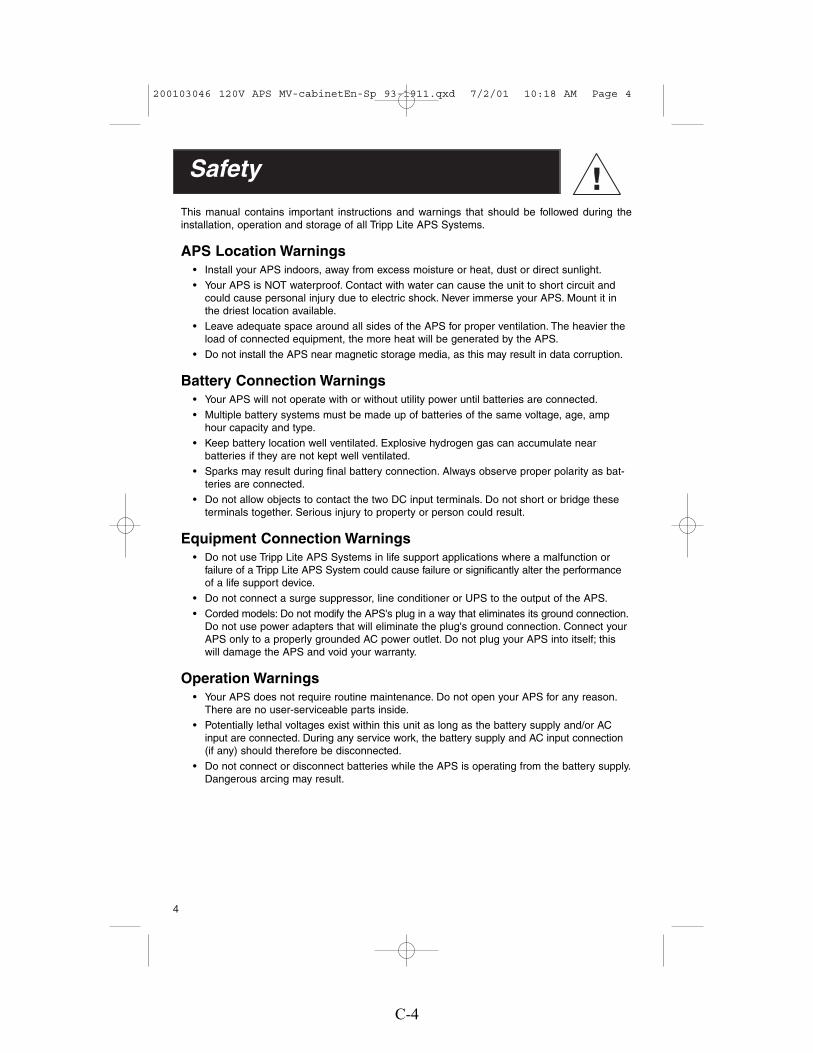
4
Safety
This manual contains important instructions and warnings that should be followed during theinstallation, operation and storage of all Tripp Lite APS Systems.
APS Location Warnings• Install your APS indoors, away from excess moisture or heat, dust or direct sunlight.
• Your APS is NOT waterproof. Contact with water can cause the unit to short circuit andcould cause personal injury due to electric shock. Never immerse your APS. Mount it inthe driest location available.
• Leave adequate space around all sides of the APS for proper ventilation. The heavier theload of connected equipment, the more heat will be generated by the APS.
• Do not install the APS near magnetic storage media, as this may result in data corruption.
Battery Connection Warnings• Your APS will not operate with or without utility power until batteries are connected.
• Multiple battery systems must be made up of batteries of the same voltage, age, amphour capacity and type.
• Keep battery location well ventilated. Explosive hydrogen gas can accumulate nearbatteries if they are not kept well ventilated.
• Sparks may result during final battery connection. Always observe proper polarity as bat-teries are connected.
• Do not allow objects to contact the two DC input terminals. Do not short or bridge theseterminals together. Serious injury to property or person could result.
Equipment Connection Warnings• Do not use Tripp Lite APS Systems in life support applications where a malfunction or
failure of a Tripp Lite APS System could cause failure or significantly alter the performanceof a life support device.
• Do not connect a surge suppressor, line conditioner or UPS to the output of the APS.
• Corded models: Do not modify the APS's plug in a way that eliminates its ground connection.Do not use power adapters that will eliminate the plug's ground connection. Connect yourAPS only to a properly grounded AC power outlet. Do not plug your APS into itself; thiswill damage the APS and void your warranty.
Operation Warnings• Your APS does not require routine maintenance. Do not open your APS for any reason.
There are no user-serviceable parts inside.
• Potentially lethal voltages exist within this unit as long as the battery supply and/or ACinput are connected. During any service work, the battery supply and AC input connection(if any) should therefore be disconnected.
• Do not connect or disconnect batteries while the APS is operating from the battery supply.Dangerous arcing may result.
200103046 120V APS MV-cabinetEn-Sp 93-1911.qxd 7/2/01 10:18 AM Page 4
C-4

44 33 22 11
5
Configuration
CONFIGURATION DIP SWITCH SETTINGS
DIP SWITCH GROUP A (All models)BATTERY TYPE / VOLTAGE POINTUsing a small tool, set the 4 “Battery Type / Voltage Point” Configuration DIP Switches, Group A(located on the front panel of your APS; see Diagram 1, p. 32) to select battery type and set thevoltage range outside of which your APS will switch to battery power.
• Select Battery Type(DIP Switch #1, Group A)CAUTION: The Battery Type DIP Switch setting must match the type of batteries you connect or your batteries may be degradedor damaged over an extended period of time. See “Battery Selection,” page 7 for more information.
Battery Type Switch Position
Gel Cell (Sealed) Battery ............................UpWet Cell (Vented) Battery ............................Down*
• Select High AC Voltage Switch To Battery Point(DIP Switch #2, Group A)
Voltage Switch Position145V ............................................................Up135V ............................................................Down*
• Select Low AC Voltage Switch To Battery Point(DIP Switches #4, Group A & #3, Group A)
Most loads will perform adequately when your APS’s High AC Voltage Point DIP Switch #2 is setto 135V and its Low AC Voltage Point DIP Switches #3 and #4 are set to 95V. However, if your APSfrequently switches to battery power due to momentary high/low line voltage swings that wouldhave little effect on equipment operation, you may wish to adjust these settings. By raising the HighAC Voltage Switch to Battery point and/or lowering the Low AC Voltage Switch to Battery Point, youmay reduce the number of times your APS switches to battery due to voltage swings.
* Factory default settings.
DIP SWITCH GROUP B (Available on Select Models) LOAD SHARING/EQUALIZE BATTERY CHARGEUsing a small tool, set the “Load Sharing” Configuration DIP Switches, #1 and #2 of Group B(located on the front panel of your APS; see Diagram 1, p. 32). DIP Switch #3, Group B shouldbe kept in the “UP” position when you are not equalizing your batteries’ charges. DIP Switch #4,Group B has different functions, or no function, depending on your APS model.
75V*#4 Down
& #3 Down
85V#4 Down & #3 Up
95V#4 Up & #3 Down
105V#4 Up & #3 Up
GelCell
WetCell*
145V
135V*
44 33 22 11
44 33 22 11 44 33 22 11 44 33 22 11
44 33 22 11
200103046 120V APS MV-cabinetEn-Sp 93-1911.qxd 7/2/01 10:18 AM Page 5
C-5

6
• Load Sharing(DIP Switches #1, Group B & #2, Group B)Your APS features a high-output battery charger that can draw a significant amount of powerfrom your line power source when charging at its maximum rate. If an APS is supplying its fullAC power rating to its connected load at the same time as it is charging, it could trip its linesource circuit breaker. Tripping this breaker will cut off AC power to your load and stop batterycharging.To reduce the chance of tripping this breaker, select APS models may be set to automaticallylimit their charger output to keep the sum of their AC load and charger power within theircircuit breakers’ rating.This charger limiting function has four settings, allowing you to choose less charger limiting forAPS configurations with higher rated breakers. The figures below show how to set your DIPSwitches to select how heavy a load can be placed on your APS before charger limiting begins.
• Equalize Battery Charge(DIP Switch #3, Group B)
This DIP Switch is momentarily engaged to begin the process of equalizing the internal resistanceof your battery's cells. This can extend the useful life of certain types of batteries; consult withyour battery's manufacturer to determine if your batteries could benefit from this process. Thecharge equalization process is automatic and once started can only be stopped by removingthe input power.SETTING PROCEDURE:1) Move to “Equalize” (DOWN) position for three seconds.2) Move to “Reset” (UP) position and leave it there.CAUTION: Battery charge equalization should only be performed in strict accordancewith the battery manufacturer's instructions and specifications.CAUTION: Do not leave DIP switch #3 in the down position after beginning process.
Battery Charge Switch Position
Reset ............................................................Up*Equalize ......................................................Down* Factory default setting.
• Disable Battery Charger (APS 2448 only)(DIP Switch #4, Group B)If you are connecting the APS 2448 to batteries with a separate charger, you may disablethe APS 2448’s built-in charger with this switch to prevent overcharging.
Battery Charger Switch Position
Disable..........................................................Up*Enable ..........................................................Down
* Factory default setting.
Reset*
Equalize
Disable*
Enable
Battery Charger Limiting PointsCharger limiting takes effect themoment any load is applied; chargeroutput falls gradually from full outputat no load to no output at full load.
* Factory default settings.Most Limiting#1 & #2 Up*
Least Limiting#1 Up & #2 Down
Charger limiting begins at when theAPS's load reaches 66% of the APS'sload rating. Charger output fallsgradually from full output at 66% ofthe APS's load rating to about 40% offull output at full load.
No Limiting#1 & #2 Down
No charger limiting occurs at anyload size.
Less Limiting#1 Down & #2 Up
Charger limiting begins when theAPS's load reaches 33% of the APS'sload rating. Charger output fallsgradually from full output at 33% ofthe APS's load rating to about 40% offull output at full load.
44 33 22 11 44 33 22 11
44 33 22 11 44 33 22 11
44 33 22 11
44 33 22 11
200103046 120V APS MV-cabinetEn-Sp 93-1911.qxd 7/2/01 10:18 AM Page 6
C-6

7
• Limit Battery Charger (APS 1012 and APS 2012 only)(DIP Switch #4, Group B)
To prevent overheating smaller batteries, the charger on these UPS systems is initially set todeliver only a fraction of its maximum power rating to connected batteries. If you are usingeither of these APS systems with a larger battery or battery system (over 100 amp-hours at12 volts for the APS 1012, over 200 amp-hours at 12 volts for the APS 2012), you may switchyour charger to full power without overheating your batteries.
Battery Charger Switch Position
Partial (1/3) Charging Power ........................Up*Full Charging Power ....................................Down* Factory default setting.
Battery SelectionSelecting Battery Type
Select a battery or system of batteries that will provide your APS with proper DC voltage and anadequate amp hour capacity.* Select ‘Deep-Cycle’ batteries to enjoy optimum performance fromyour APS. Batteries of either Wet-Cell (vented) or Gel-Cell/Absorbed Glass Mat (sealed) constructionare ideal. 6 Volt “golf-cart, Marine Deep-Cycle or 8D Deep-Cycle batteries are also acceptable.** * Even though APS models are high-efficiency converters of electricity, their rated output capacities are limited by the amp-hour size
of the external batteries. ** You must set Configuration DIP Switch #1, Group A (Battery Type) to match the type of batteries youconnect or your batteries may be degraded or damaged over an extended period of time. See "APS Configuration," page 5 for moreinformation.)
Selecting Battery Amp Hour Capacity
Step 1:Add the Wattage Ratings of your connected equipment to determine the Total Wattage Required.*
Step 2:Divide the Total Wattage Required (from Step 1) by the battery voltage to determine the DCAmperes Required.
Step 3:Multiply the DC Amperes Required (from Step 2) by the number of hours you estimate will passwithout AC power before your battery can recharge to determine a Battery Amp-Hours RequiredRough Estimate.**
Step 4:Compensate for inefficiency by multiplying your Battery Amp-Hour Required Rough Estimate (fromStep 3) by 1.2 to determine how many amp-hours of battery backup (from one or several batteries)you should connect to your APS. Note that the Amp-Hour ratings of batteries are usually given fora 20 hour discharge rate. Actual Amp-Hour capacities are less when batteries are discharged atfaster rates: batteries discharged in 55 minutes provide only about 50% of their listed Amp-Hourratings, while batteries discharged in 9 minutes provide as little as 30% of their Amp-Hour ratings.* The wattage rating is usually stated in the equipment's manuals or on their nameplates. If your equipment is rated in amperes, convert
to watts by multiplying the ampere rating by your nominal AC line voltage (120). ** Your charging amps multiplied by the charginghours must exceed the discharge amp-hours taken from the batteries between charges or you will eventually run down your battery bank.
1/3 Power*
Full Power
44 33 22 11
200103046 120V APS MV-cabinetEn-Sp 93-1911.qxd 7/2/01 10:18 AM Page 7
C-7

8
Mounting (Optional*)(See Diagram 2, p. 32).
User must supply all fasteners and brackets and verify their suitability for use with the intendedmounting surface. Turn your APS PowerVerter and connected equipment OFF before mounting.
• Install two 8 mm (1/4 in.) fasteners (A) into a rigid horizontal surface using the measurementsin the diagram. Leave the heads of fasteners raised slightly above the surface in order toengage the slots in the APS’s feet.
• Slide PowerVerter forward to fully engage the fasteners in the APS’s feet. Install two 8 mm(1/4 in.) fasteners (B) into the surface, through the slots in the APS’s two unsecured feet.Tighten the screws to secure the APS in position.
* Horizontal mounting should be used for all vehicular applications. Due to their size and weight, all APS PowerVertersystems in vehicles should be mounted on a rigid horizontal (not vertical) surface, mounting plate or bracket beforebattery connection.
Battery Connection (Standard)1. Connect your APS’s positive DC Terminal directly to a fuse.
UL recommends that you install a recognized UL component fuse block and fuse within 18 inchesof the battery.The fuse's rating must equal or exceed the Minimum DC Fuse Rating listed in yourAPS model's specifications on pages 14 or 15.
2. Choose a battery configuration appropriate to your batteries.• Single Battery Connection: Refer to Diagram 4, page 33. When using a single battery, its
voltage must be equal to the voltage of your APS's Inverter Nominal Input Voltage (seespecs).
• Parallel Battery Connection: Refer to Diagram 5, page 33. When using multiple batteries inparallel, each battery's voltage must be equal to the voltage of your APS's Inverter NominalInput Voltage (see specs).
• Series Battery Connection: Refer to Diagram 6, page 33. When using multiple batteries inseries, all batteries must be equal in voltage and amp hour capacity, and the sum of theirvoltages must be equal to the voltage of your APS's Inverter Nominal Input Voltage (seespecs).
3. Use 2/0 gauge wire ONLY to make external battery connections.Tighten battery terminals to a torque of 4 N-m.
WARNING! Failure to follow these instructions can lead to product failure due to excessive heating!
Battery connection cable lengths should be short as possible, and must not exceed theMaximum Cable Length listed under Specifications, page 14. Shorter and heavier gauge cablinglimits DC voltage drop and allows for maximum transfer of current.* You must tighten your batteryterminals to approximately 4 Newton-meters of torque to create an efficient connection and preventexcessive heating. Insufficiently tightening terminals could void your PowerVerter's warranty.*APS models are capable of delivering a much higher wattage output for brief periods of time. Wiring should be configured tohandle this brief high-current draw. Though your APS is a high-efficiency converter of electricity, its rated output capacity is limitedby the length and gauge of the wires running from the battery to the APS.
Battery Connection (DC Vehicular)APS systems may be permanently mounted in a car, truck or boat and connected to draw powerfrom the vehicle's battery. Note: An APS can ONLY be connected to vehicle batteries withvoltage that matches the APS's Nominal DC Input—12V vehicle batteries to 12V Nominal DCInput APS systems, etc. (See Specifications). There are two main ways to make this sort of
200103046 120V APS MV-cabinetEn-Sp 93-1911.qxd 7/2/01 10:18 AM Page 8
C-8

9
vehicular battery connection. Choose the Basic Connection if you are running light hand tools orother small appliances for a brief period of time (see Diagram 7, p. 34). Choose the AdvancedConnection if you are using your APS to power heavy loads for extended periods of time (seeDiagram 8, p. 34). The Advanced Connection incorporates a battery isolator and separate batterysystem to provide battery power to your APS while preventing it from draining your vehicle's battery. Note: Depending on your application, you may require more than one Deep Cycle Battery.Caution: Never operate your APS from an alternator without a battery connected as shown in Diagrams 7 or 8, p. 34.
AC ConnectionBefore AC connection, match the power requirements of yourequipment with the power output of your APS to avoid overload.When figuring the power requirements of your equipment, do not confuse “continuous” power ratings with “peak” power ratings. Electric motors require more power to turn on (“peak power”) than they require to run continuously. “Peak” power ratings are usually 2 to 5 times “Continuous”ratings. Most electric motors require “peak power” only when they are first turned on. The electricmotors in equipment such as refrigerators and sump pumps, however, constantly turn on and offaccording to demand. These motors require “peak power” at multiple, unpredictable times duringtheir operation.
Hardwired Electrical Connections(All hardwire models)
(See Diagram 3, p. 32).
Consult a qualified electrician and follow all applicable electrical codes and requirements.
HARDWIRE PROCEDURE1) Remove screws and cover plate from your APS's Hardwire AC electrical box. Remove the
knockout covers closest to the desired electrical source and to your equipment.
2) Thread your wires through strain reliefs and through the knockouts.
3) Connect both input and output ground wires to the ground (green) terminal.
4) Connect the incoming hot wire to the input hot (brown) terminal.
5) Connect the incoming neutral wire to the input neutral (blue) terminal.
6) Connect the outgoing hot wire to the output hot (black) terminal.
7) Connect the outgoing neutral wire to the output neutral (white) terminal.
8) Tighten and affix strain reliefs. Replace cover plate and tighten screws.
AC Input Electrical Connection(All corded models)
Plug the line cord into an outlet providing 120V AC, 60 Hz. power. Make sure that the circuit youconnect your APS to has adequate overload protection, such as a circuit breaker or a fuse.
AC Output Electrical Connection(All corded models)
Simply plug your equipment into the unit's AC receptacles
Set Operating Mode Switch
• Switch to “AUTO/REMOTE” when you are using connected equipment. ADVANTAGE:Uninterruptible power supply. Provides battery backup power during blackouts or brownouts.
Note: When the switch is in the “AUTO/REMOTE” position, you can operate a user-suppliedswitch to transfer between battery-backup and charge-only modes. (See RemoteConnector manual for more information.)
200103046 120V APS MV-cabinetEn-Sp 93-1911.qxd 7/2/01 10:18 AM Page 9
C-9

10
Set Operating Mode Switch continued
• Switch to “CHARGE ONLY” when you are not using connected equipment.(WARNING! APS will not provide battery backup!) ADVANTAGES: A) Continues to chargebattery when power is present, and B) Turns OFF the APS’s inverter, preventing battery drainduring blackouts or brownouts.
• Switch to “OFF” to completely turn off the APS and connected equipment or to reset the APSafter it has shut down due to overload or overheating.
Switches, Indicator Lights & Other Features
(See Diagram 9, p. 35 to locate the following switches, indicator lights and other features.)
Switches
1. Operating Mode Switch (All models)This switch selects the APS operating mode (either “AUTO/REMOTE”, “OFF” or “CHARGEONLY”). See “Set Operating Mode Switch”, pg. 10 to select the optimum setting for this switch.
2. “CONFIGURATION SWITCHES”—DIP Switch Group A (All models)These four switches must be set for the type of battery your APS will be connected to and the voltagepoints at which your APS will switch to battery power. See “Configuration”, pg. 5 to select the optimumsettings for these switches.
3. “CONFIGURATION SWITCHES”—DIP Switch Group B (Select models only)These DIP Switches allow you to equalize the internal resistance of your battery's cells and set thepercentage of your model's maximum load at which the APS will limit battery charging. See“Configuration”, pg. 7 to select the optimum settings for these switches.
Indicator Lights
4. “LINE” (All models)This green light will turn continuously ON whenever connected equipment is receiving utility-suppliedAC power and your APS is set to “AUTO/REMOTE”, meaning that it will provide battery backup ifutility power fails. It will flash intermittently when connected equipment is receiving utility power andyour APS's Operating Mode Switch is set to “CHARGE ONLY” to warn you that the APS's inverteris OFF and that the APS WILL NOT provide battery backup during blackouts, brownouts or overvoltages.
5. “INV” (Inverting—all models)This yellow light will turn continuously ON whenever connected equipment is receiving battery-supplied AC power (during a blackout, brownout or overvoltage while connected to utility power orwhen connected to batteries during vehicular operation).
6. “LOAD” (All models)This red light will turn continuously ON when the APS’s load is between 80% and 110% of capacity.The light will flash intermittently when the APS's inverter shuts down due to a severe overload oroverheating. If this happens, turn Operating Mode Switch OFF. Remove the overload and let theunit cool. You may then turn the APS ON after it cools.
7. “CUT/BOOST” (VR models only)These lights will turn ON whenever your APS is automatically correcting high (CUT) or low(BOOST) AC line voltage. This is a normal, automatic operation of your APS that does not drainbattery power, and no action is required on your part.
200103046 120V APS MV-cabinetEn-Sp 93-1911.qxd 7/2/01 10:18 AM Page 10
C-10

11
8. “BATTERY HI/MED/LO” (All models)These three lights will turn ON in several sequences to show the approximate charge level andvoltage of your connected battery bank and alert you to several fault conditions:
BATTERY CHARGE INDICATION (Approximate)
Indicator CapacityGreen 91% - FullGreen & yellow 81% - 90%Yellow 61% - 80%Yellow & red 41% - 60%Red 21% - 40%All three lights off 1% - 20%Flashing red 0% (Inverter shutdown)
All three lights flash slowly* Excessive dischargeAll three lights flash quickly** Overcharge
* Approximately 1/2 second on, 1/2 second off. See Troubleshooting section.** Approximately 1/4 second on, 1/4 second off. May also indicate a battery charger fault exists. See Troubleshooting section.
Other Features
9. DC Input Terminals (All models)The terminals’ lug screws secure the wires leading from your external battery or battery system.Your battery or battery system must provide your APS with proper DC voltage and your equipmentwith an adequate amp hour capacity. See Battery Selection section, pg. 7 for more information.
10. AC Receptacles: NEMA 5-15R (Corded models only)These receptacles allow you to connect equipment that would normally be plugged into a utilityoutlet. They feature ground fault indicator switches that trip when the receptacles are in danger ofshort circuiting. If the switches trip, press to reset them when the short circuit situation is remedied.
11. AC Input Line Cord: NEMA 5-15P fixed (Corded models only)This cord should be plugged into a 120V, 60 Hz, dedicated 15 Amp AC utility outlet. DO NOT plugthe cord into the APS’s AC receptacles.
12. Hardwire AC Input/Output Terminal Strip (Hardwire models only)Use the lug screws on these terminals to secure hardwire connections for AC input and output.See pages 9 & 32 for wiring instructions.
13. Resettable Circuit Breakers (All models)These circuit breakers protect your APS against damage due to input or output overload. If abreaker trips, remove some of the load on the APS to prevent overload, then wait 1 minute to allowcomponents to cool before resetting the circuit breaker.
14. Remote Module Connector (All models)The front panel of all models has an RJ 45 receptacle for use with the optional remote module.(Module is included with all VR models.) See the installation instructions packed with the remotemodule.
15. Load Sense Potentiometer (All models)In order to save battery power, the APS’s inverter automatically shuts off when no load is connected.When the unit detects a load, it automatically turns the inverter on. Users may choose the minimumload the APS will detect by adjusting the Load Sense Potentiometer. Using a small tool, turn thepotentiometer clockwise to lower the minimum load that will be detected, causing the inverter toturn on for smaller loads. When the potentiometer is turned fully clockwise, the inverter will operateeven when there is no load.Turn the potentiometer counterclockwise to increase the minimum loadthat will be detected, causing the inverter to stay off until the new minimum load is reached.The factory setting for the potentiometer is fully clockwise, but in areas with frequent power interruptions,the potentiometer should be adjusted counterclockwise until the inverter is only in operation whenthe APS’s load is in use.
200103046 120V APS MV-cabinetEn-Sp 93-1911.qxd 7/2/01 10:18 AM Page 11
C-11

12
Limited WarrantyTripp Lite warrants its products to be free from defects in materials and workmanship for a period of one year (domestic) or 120days (export) from the date of initial purchase. Tripp Lite’s obligation under this warranty is limited to repairing or replacing (at itssole option) any such defective products. To obtain service under this warranty you must obtain a Returned Material Authorization(RMA) number from Tripp Lite or an authorized Tripp Lite service center. Products must be returned to Tripp Lite or an authorizedTripp Lite service center with transportation charges prepaid and must be accompanied by a brief description of the problemencountered and proof of date and place of purchase. This warranty does not apply to equipment which has been damaged by accident,negligence or misapplication or has been altered or modified in any way. This warranty applies only to the original purchaser whomust have properly registered the product within 10 days of purchase.
EXCEPT AS PROVIDED HEREIN, TRIPP LITE MAKES NO WARRANTIES, EXPRESS OR IMPLIED, INCLUDING WARRANTIESOF MERCHANTABILITY AND FITNESS FOR A PARTICULAR PURPOSE. Some states do not permit limitation or exclusion ofimplied warranties; therefore, the aforesaid limitation(s) or exclusion(s) may not apply to the purchaser.
EXCEPT AS PROVIDED ABOVE, IN NO EVENT WILL TRIPP LITE BE LIABLE FOR DIRECT, INDIRECT, SPECIAL, INCIDENTALOR CONSEQUENTIAL DAMAGES ARISING OUT OF THE USE OF THIS PRODUCT, EVEN IF ADVISED OF THE POSSIBILITYOF SUCH DAMAGE. Specifically, Tripp Lite is not liable for any costs, such as lost profits or revenue, loss of equipment, loss of useof equipment, loss of software, loss of data, costs of substitutes, claims by third parties, or otherwise.
Maintenance & ServiceMaintenanceYour APS model requires no maintenance but should be kept dry at all times. Periodically checkall cable connections both at the unit and at the battery. Clean and tighten connections as necessary.
ServiceIf returning your APS to Tripp Lite, please pack the APS carefully, using the ORIGINAL PACKINGMATERIAL that came with the unit. Enclose a letter describing the symptoms of the problem. If theAPS is within the warranty period, enclose a copy of your sales receipt.
200103046 120V APS MV-cabinetEn-Sp 93-1911.qxd 7/2/01 10:18 AM Page 12
C-12

13
Try these remedies for common APS problems before calling for help. Call Tripp Lite Customer Service at (773)869-1234 before returning your APS for service.
SYMPTOM PROBLEMS CORRECTIONS
APS does not provide APS not properly connected to Connect APS to utility power.AC output (AC input present) utility power.
Circuit breaker is tripped. Reset circuit breaker.
APS shutdown due to excessive Turn APS “OFF”. Wait 1 minute and battery voltage, indicating possible switch to “AUTO/REMOTE”.
charger failure. Line disconnected to prevent permanent battery damage.
APS is set to “OFF” Set APS to “AUTO/REMOTE” or “CHARGE-ONLY”.
APS does not provide Circuit breaker is tripped. Reset circuit breaker.AC output (AC input absent)
Operating Mode Switch is set Set Operating Mode Switch to “AUTO/to “CHARGE ONLY”. REMOTE.”
Load or High Temperature fault. Turn APS “OFF”. Wait 1 minute. Remove overload. Switch to “AUTO/REMOTE”.
Excessive battery discharge. Check battery condition.
APS will not charge the Connected batteries are dead. Check and replace old batteries.battery (AC input present)
Battery fuse* is blown. Check and replace fuse.
Battery cabling* is loose or degraded. Check and tighten or replace cabling.
APS charger failure. Turn APS “OFF”. Wait 1 minute and switch to “AUTO/REMOTE”. If automatic shutdown occurs, call Tripp Lite Customer Service.
All APS Indicator Lights are This is normal if the APS is set —OFF (AC input absent) to “CHARGE-ONLY”
All APS Indicator Lights are Excessive battery discharge. Use an auxiliary charger* to raise OFF (AC input is present or battery voltage. Check external batteryabsent) connections and fuse. Automatically
resets when condition is cleared.
All APS Battery Indicator Excessive battery discharge. Use an auxiliary charger* to raiseLights are slowly flashing. battery voltage. Automatically resets
when condition is cleared.
APS “LO” Battery Light Inverter shutdown because battery Reset by cycling control switch to flashing voltage dropped too low for more “OFF” position then to “AUTO/
than 5 seconds. Protects battery REMOTE”.from permanent damage.
All APS Battery Lights are High battery voltage shutdown Check all charging sources. Reset by rapidly flashing during Charge mode. cycling control switch to "OFF" then to “AUTO/REMOTE” or “CHARGE-ONLY”.
APS “LOAD” Indicator Light Inverter overload caused by Reset by reducing load and cycling controlis rapidly flashing excessive load or short circuit. switch to “OFF” position then to “AUTO/
If sustained for more then 5 REMOTE”.seconds the Inverter is shutdown.
*User supplied
Troubleshooting
200103046 120V APS MV-cabinetEn-Sp 93-1911.qxd 7/2/01 10:18 AM Page 13
C-13

14
Specifications (Corded Models)
CORDED MODELS: APS 1012 APS 1024Weight: 26.4 lbs. 26.4 lbs.
INVERTERContinuous power (@ 20° C): 900 W 1000 W
Surge power (5 seconds): 1800 W 2000 W
Efficiency (Full Load): 90% 90%
Minimum DC Fuse Rating: 225A 125A
DC Input Current @ Nominal V DC Full Load 95 A 47 ANo Load 2.2 A* 1.3 A*
Nominal Input Volts: 12 VDC 24 VDC
DC Input Voltage Range: 10-15 VDC 20-30 VDC
Nominal Output Volts: 120 VAC ±5% 120 VAC ±5%
Nominal Output Frequency: 60 Hz ±.3% 60 Hz ±.3%
BATTERY CHARGER
Charging Capacity DC: 30 A 15 A
Maximum Cable Length 2 ft. 7 ft.
Acceptance Volts VDC: Selectable Selectable14.4 V**/14.2 V Wet**/Gel 28.8 V**/28.4 V Wet**/Gel
Float Volts VDC (w/gel): 13.3 V (13.6 V) 26.6 V (27.2 V)
Input Voltage AC: 120 V 120 V
Input Current AC: 8 A 8 A
LINE VAC OPERATION
Minimum Input AC Volts: Selectable 75**,85, 95, or 105 VAC Selectable 75**,85, 95, or 105 VAC
Maximum Input AC Volts(Continuous, Charger at Maximum): Selectable 135** or 145 VAC Selectable 135* *or 145 VAC
Maximum Input Current(Continuous, Charger at Maximum): 12 A 16 A
Input Frequency: 60 Hz ±10% 60 Hz ±10%
Maximum Output AC (Continuous): 8.3 A 8.3 A
Automatic Transfer Time: 4-6 ms 4-6 ms
*Load sense can reduce this to 1/30 of the listed current. **Factory default setting.
200103046 120V APS MV-cabinetEn-Sp 93-1911.qxd 7/2/01 10:18 AM Page 14
C-14

15
Specifications (Hardwired Models)HARDWIRED MODELS: APS 2012 APS2424Weight: 38.0 lbs. 41.0 lbs.
INVERTERContinuous power (@ 20° C): 2000 W 2400 WSurge power (5 seconds): 4000 W 4800 WEfficiency (Full Load): 90% 90%Minimum DC Fuse Rating: 500A 300ADC Input Current @ Nominal V DC
Full Load 192 A 112 ANo Load 2.5 A* 1.5 A*
Nominal Input Volts: 12 VDC 24 VDCDC Input Voltage Range: 10-15 VDC 20-30 VDCNominal Output Volts: 120 VAC ±5% 120 VAC ±5%Nominal Output Frequency: 60 Hz ±.3% 60 Hz ±.3%
BATTERY CHARGERCharging Capacity DC: 60 A 30 AMaximum Cable Length 1 ft. 3 ft.Acceptance Volts VDC: Selectable Selectable
14.4 V**/14.2 V Wet**/Gel 28.8 V**/28.4 V Wet**/Gel
Float Volts VDC (w/gel): 13.3 V (13.6 V) 26.6 V (27.2 V)
Input Voltage AC: 120 V 120 V
Input Current AC: 16 A 16 A
LINE VAC OPERATIONMinimum Input AC Volts: Selectable 75**,85, 95, or 105 VAC Selectable 75**,85, 95, or 105 VACMaximum Input AC Volts(Continuous, Charger at Maximum): Selectable 135** or 145 VAC Selectable 135** or 145 VACMaximum Input Current(Continuous, Charger at Maximum): 32 A 36 AInput Frequency: 60 Hz ±10% 60 Hz ±10%Maximum Output AC (Continuous) 16.7 A 20 AAutomatic Transfer Time: 4-6 ms 4-6 ms
HARDWIRED MODELS (Cont.): APS 2448 APS3636VRWeight: 38.0 lbs. 56.9 lbs.
INVERTERContinuous power (@ 20° C): 2400 W 3600 WSurge power (5 seconds): 4800 W 7200 WEfficiency (Full Load): 90% 89%Minimum DC Fuse Rating: 300A 300ADC Input Current @ Nominal V DC
Full Load 56 A 114 ANo Load 1.5 A* 1.7 A*
Nominal Input Volts: 48 VDC 36 VDCDC Input Voltage Range: 40-60 VDC 30-45 VDCNominal Output Volts: 120 VAC ±5% 120 VAC ±5%Nominal Output Frequency: 60 Hz ±.3% 60 Hz ±.3%
BATTERY CHARGERCharging Capacity DC: 15 A 30 AMaximum Cable Length 12 ft. 4.5 ft.Acceptance Volts VDC: Selectable Selectable
57.6 V**/56.8 V Wet**/Gel 43.2 V**/42.6 V Wet**/GelFloat Volts VDC (w/gel): 53.2 V (54.4 V) 39.9 V (40.8 V)Input Voltage AC: 120 V 120 VInput Current AC: 16 A 24 A
LINE VAC OPERATIONMinimum Input AC Volts: Selectable 75**,85, 95, or 105 VAC Selectable 75**,85, 95, or 105 VACMaximum Input AC Volts(Continuous, Charger at Maximum): Selectable 135** or 145 VAC Selectable 135** or 145 VACMaximum Input Current(Continuous, Charger at Maximum): 33 A 54 A***Input Frequency: 60 Hz ±10% 60 Hz ±10%Maximum Output AC (Continuous) 20 A 30 AAutomatic Transfer Time: 4-6 ms 4-6 ms
*Load sense can reduce this to 1/30 of the listed current. **Factory default setting. ***When AVR is boosting incoming current.
200103046 120V APS MV-cabinetEn-Sp 93-1911.qxd 7/2/01 10:18 AM Page 15
C-15

16Copyright © 2001 Tripp Lite. Propiedad Literaria de Tripp Lite 2001. Reservados todos los derechos.
1111 W. 35th StreetChicago, IL 60609 USA
Servicios a Clientes: (773) 869-1234www.tripplite.com
Configuración y Conexión: p. 20 - 25
Características: p. 25 - 27
Garantía: p. 28
Resolución de Problemas: p. 29
Seguridad: p. 19
Introducción: p. 17 - 18
Mantenimiento y Servicio: p. 27
Especificaciones: p. 30 - 31
Manual de Operación
APS PowerVerter®
Fuentes Alternativas de Energía
(120V, 60 Hz)
• Con Voltaje y Frecuencia Controlada• Energía de Cresta - Alta Eficiencia
200103046 120V APS MV-cabinetEn-Sp 93-1911.qxd 7/2/01 10:18 AM Page 16
C-16

17
Introducción
¡Felicitaciones! Usted ha adquirido el inversor / cargador de batería integrado más avanzado y con más características en el mercado. Este modelo APS suministrará a sus equipos energía de CA mientras ésta esté presente. Durante un apagón, caída o subida de voltaje, esta unidad cambia automáticamente a la batería externa para suministrar energía de CA de voltaje y frecuencia controlada.
• Salida de Alta EficienciaLa circuitería avanzada de este sistema APS produce una conversión de alta eficiencia de CD aCA, minimizando así la pérdida de energía. Esto le permite a usted operar los equipos conectadospor períodos prolongados entre carga y carga de las baterías. Este sistema mantendrá la salidade alta eficiencia aún mientras disminuye la carga de las baterías.
• Protección Automática contra SobrecargasSi usted sobrecarga este APS, la unidad protegerá automáticamente sus baterías y a sí mismacontra daños.
• Cambio Rápido de CargaEl sistema APS brinda alimentación eléctrica ininterrumpida. Si se pierde el suministro decorriente alterna de la red, el APS conmutará en 6 milisegundos o menos a la alimentación porpilas de reserva, de modo que sus equipos funcionarán sin interrupción.
• Luces Indicadoras de Funciones MúltiplesVarios juegos de luces indicadoras de funciones múltiples le mantienen constantemente informadoacerca de los niveles de carga de la batería, fallas y operación del sistema APS.
• Interruptores de Operaciones MúltiplesUna variedad de interruptores ajustables por el usuario le ofrecen convenientes opciones paraoperar el sistema APS. Usted puede seleccionar el nivel de voltaje de activación del inversor delAPS para maximizar la protección de sus equipos y minimizar el desgaste de las baterías; regularel APS para incrementar la eficiencia de recarga de acuerdo al tipo de baterías utilizadas; y hastaactivar la operación de su APS por control remoto.
200103046 120V APS MV-cabinetEn-Sp 93-1911.qxd 7/2/01 10:18 AM Page 17
C-17

18
Cargador Avanzado de 3 Etapas para Baterías
Este sistema APS recargará sus baterías másrápido que otros cargadores convencionalesdebido a que su perfil de recarga de 3 etapas(Alimentación en Masa, Absorción yAlimentación por Flotador) provee óptimorendimiento independientemente del tipo debaterías que usted utilice (Húmeda o de Gel).*Además, el sistema avanzado de recargaprotege contra exceso de carga y descargapara prolongar la vida útil de sus baterías.
* Los niveles de Absorción y Alimentación por Flotador varíande acuerdo al tipo de baterías conectadas. Esta unidad puede serregulada para operar con Baterías Húmedas o de Gel.
• Regulación Automática de Voltaje (Modelos Selectos Solamente)Los modelos “VR” regulan el voltaje de entrada de CA, elevando o disminuyendo dicho voltajepara mantener sus equipos en operación durante caídas y subidas de voltaje sin desgastar lasbaterías.
• Compartición de Carga (Modelos selectos solamente)Algunos modelos APS pueden ser regulados para limitar sus propias funciones de carga y asírecargar sus baterías lo más rápido posible sin sobrecargar sus circuitos de entrada de energía.
• Inversor con Salida de Frecuencia ControladaTodos los modelos APS incluyen Inversores con Salida de Frecuencia Controlada para permitirque los equipos que dependen de la frecuencia de la línea de CA (como computadoras,grabadoras de video, lectores de CD, grabadoras de audio, relojes eléctricos y tocadiscos)operen correctamente.
• Tarjetas de Circuitos ProtegidasTarjetas de circuitos son protegidas por revestimiento de conformación de silicona transparente.
VO
LTA
JE D
E B
AT
ER
ÍAEtapa 3
Alimentación por Flotador
Etapa 2Absorción
TIEMPOPERFIL DE CARGA
Eta
pa
1 A
limen
taci
ón
en
Mas
a
200103046 120V APS MV-cabinetEn-Sp 93-1911.qxd 7/2/01 10:18 AM Page 18
C-18

19
Seguridad
Este manual contiene advertencias e instrucciones importantes que deben seguirse durante lainstalación, operación y almacenaje de todos los Sistemas APS de Tripp Lite.
Precauciones Sobre la Ubicación del APS• Instale este sistema bajo techo, lejos de calor o humedad excesivos, polvo o luz solar directa.
• Deje suficiente espacio alrededor del APS para permitir ventilación adecuada.
• No instale este sistema APS cerca de dispositivos magnéticos de memoria ya que estopuede producir la corrupción de los datos grabados.
• Los modelos APS NO SON impermeables o resistentes al agua. El contacto con aguapuede causar cortocircuitos y lesiones corporales debido a choques eléctricos. No sumerjaeste APS. Instálelo en el lugar más seco posible.
Precauciones Sobre la Conexión de Baterías• El APS no funcionará, con alimentación de la red o sin ella, hasta que se conecten las pilas.
• Los sistemas múltiples de baterías deben estar formados por baterías del mismo tipo,voltaje, edad y capacidad en amperios/hora.
• Mantenga ventilación adecuada. Gases hidrógenos explosivos pueden acumularse cercade las baterías si el área no está bien ventilada.
• Durante la conexión final de las baterias pueden producirse chispas.
• No permita que ningún objeto foráneo entre en contacto con las terminales de entrada deCD. No conecte estas terminales entre sí con ningún objeto. Esto puede producir seriaslesiones corporales o daños a objetos.
Precauciones Sobre la Conexión de Equipos• No utilice los Sistemas APS de Tripp Lite en aplicaciones para el soporte de la vida
humana donde una falla del APS pueda causar anomalías o alterar significativamenteel rendimiento del dispositivo de soporte de vida.
• No conecte supresores de sobretensiones transitorias, reguladores de voltaje, acondicionadoresde línea o no-breaks / sistemas UPS a los receptáculos de salida de esta unidad.
• Modelos con cables: no modifique el enchufe del APS de forma tal que se elimine la conexióna tierra. No use adaptadores de potencia que eliminen la conexión a tierra del enchufe.Conecte el APS exclusivamente a tomas de corriente alterna debidamente conectadas atierra. No conecte el APS a sí mismo; con ello se dañaría el APS y quedaría sin efecto lagarantía.
Precauciones de Operación• Este sistema APS no requiere mantenimiento rutinario alguno. No abra este sistema APS
por ninguna razón. No existen partes interiores que puedan ser reparadas por el usuario.
• Existen voltajes potencialmente letales dentro de esta unidad mientras las baterías esténconectadas. Durante cualquier procedimiento de servicio, siempre deben desconectarse lasbaterías y la entrada de CA (cuando sea necesario).
• No conecte o desconecte baterías mientras el sistema APS esté operando con la energíade las baterías.
200103046 120V APS MV-cabinetEn-Sp 93-1911.qxd 7/2/01 10:18 AM Page 19
C-19

20
ConfiguraciónRegulación de los Interruptores DIP de Configuración
GRUPO A DE INTERRUPTORES DIP (Todos los modelos)TIPO DE BATERÍAS / PUNTOS DE VOLTAJE
Usando una herramienta pequeña, ajuste los 4 Interruptores DIP de Configuración, Grupo A:“Battery Type / Voltage Point” (tipo de baterías / punto de voltaje) ubicados en el panel frontal delsistema APS (vea el Diagrama 1, página 32) para seleccionar el tipo de baterías que desea utilizar y programar el rango de voltaje para el cambio automático del sistema APS a energía debatería.
• Seleccione el Tipo de Baterías(Interruptor DIP No. 1, Grupo A)
PRECAUCION: El Interruptor DIP “Battery Type” (tipo de baterías), para seleccionar el tipo de baterías, debe ser colocadoen la posición correcta y de acuerdo al tipo de baterías utilizadas para evitar daños o desgaste durante un período extendidode tiempo. Refiérase a la sección “Selección de Baterías” en la página 22 para obtener más información.
Tipo de Batería Posición del Interruptor
Batería de Gel (Sellada) ......................ArribaBatería Húmeda (Ventilada) ................Abajo*
• Seleccione el Punto Alto de Voltaje de CApara el Cambio a Batería(Interruptor DIP No. 2, Grupo A)Voltaje Posición del Interruptor145V ....................................................Arriba135V ....................................................Abajo*
• Seleccione el Punto Bajo de Voltaje de CApara el Cambio a Batería(Interruptores DIP No. 4, Grupo A y No. 3, Grupo A)
La mayoría de las cargas funcionarán correctamente cuando el Interruptor DIP No. 2 para el ajustedel Punto Alto de Voltaje de CA está regulado a 135 V y los Interruptores DIP No. 3 y No. 4 parael ajuste del Punto Bajo de Voltaje de CA están regulados a 95 V. No obstante, si su sistema APScambia frecuentemente a batería debido a las fluctuaciones de alto / bajo voltaje que no interfierencon la operación de sus equipos, usted pude cambiar estos ajustes. Incrementando el Punto Altode Voltaje de CA para el Cambio a Batería y/o disminuyendo el Punto Bajo de Voltaje de CA parael Cambio a Batería, usted puede reducir el número de veces que su sistema APS cambia abatería debido a fluctuaciones de voltaje.* Regulación de fábrica
GRUPO B DE INTERRUPTORES DIP (Modelos Selectos)COMPARTICION DE CARGA / IGUALAR CARGA DE BATERIAS
Usando una herramienta pequeña, ajuste los Interruptores DIP de Configuración “Load Sharing”(compartición de carga) del Grupo B (ubicados en el panel frontal del sistema APS; vea elDiagrama 1, página 32). El Interruptor DIP No.3 del Grupo B debe estar en la posición “UP” (haciaarriba) cuando usted no desee igualar la carga de las baterías. El interruptor DIP No. 4, Grupo Btiene diferentes funciones, o no función alguna, de acuerdo con el sistema APS.
145V
135V*
75V*#4 Abajo
& #3 Abajo
85V#4 Abajo
& #3 Arriba
95V#4 Arriba
& #3 Abajo
105V#4 Arriba
& #3 Arriba
Batería de Gel
Batería Húmeda
44 33 22 11
44 33 22 11
44 33 22 11 44 33 22 11 44 33 22 11 44 33 22 11
200103046 120V APS MV-cabinetEn-Sp 93-1911.qxd 7/2/01 10:18 AM Page 20
C-20

• Compartición de Carga(Interruptores DIP No. 1 y No. 2, Grupo B)
Este sistema APS incluye un cargador de alta salida para baterías que puede demandar una cantidadconsiderable de energía de su fuente de CA mientras está recargando a su índice máximo. Si el APSestá suministrando su índice completo de energía de CA a la carga conectada al mismo tiempo queestá recargando las baterías, podría saltar el interruptor de circuitos correspondiente a la fuente delínea. Al saltar este interruptor de circuitos se cortará la energía de CA suministrada a sus equiposy se suspenderá la función de recarga de las baterías.Para reducir la posibilidad de tal evento, algunos sistemas APS pueden ser regulados para limitarautomáticamente la salida del cargador y mantener la suma de la carga conectada de CA y de laenergía del cargador dentro de los límites del interruptor de circuitos.Esta función de limitación del cargador tiene cuatro posiciones para permitirle escoger una menor limitación del cargador para configuraciones de sistemas APS con fusibles de mayor capacidad. Losdiagramas en esta página representan las instrucciones para regular los Interruptores DIP y seleccionar la cantidad de carga que puede conectarse al sistema APS antes de que se active la limitación automática del cargador.
• Igualar la Carga de Baterías(Interruptores DIP No. 3, Grupo B)Este interruptor DIP se acciona momentáneamente para iniciar el proceso de igualar laresistencia interna de las pilas. Con ello se prolonga la vida útil de algunos tipos de pilas;consulte con el fabricante de sus pilas para conocer si éstas se beneficiarían con dichoproceso. El proceso de igualación de carga es automático y una vez iniciado sólo se puededetener si se interrumpe la alimentación de electricidad.
PROCEDIMIENTO DE REGULACION:1) Mueva el interruptor hacia abajo hasta la posición “Equalize” (igualar) por tres segundos.
2) Mueva el interruptor hacia arriba hasta la posición “Reset” (restablecer) y manténgalopermanentemente en esta posición.PRECAUCION: El procedimiento para igualar la carga de las baterías debe ejecutarse como lo indican lasinstrucciones y especificaciones del fabricante de las baterías.
PRECAUCION: no deje el interruptor DIP # 3 de abajo después de iniciar el proceso.Carga de Baterías Posición del InterruptorRestablecer ..................................Arriba*Igualar ..........................................Abajo* Regulación de fábrica
• Desactivar el Cargador de Baterías (APS 2448 únicamente)(Interruptor DIP #4, Grupo B)Si desea conectar el APS 2448 a baterías con cargador separado, usted debe desactivar elcargador integrado del APS 2448 para prevenir sobrecargas.
Cargador de Baterías Posición del InterruptorDesactivar ..............................Arriba*Activar ....................................Abajo* Posición de fábrica.
21
Desactivar*
Activar
Restablecer*
Igualar
La limitación del cargador se activa cuandola carga conectada al sistema APS llega a66% de la capacidad máxima del APS. Lasalida del cargador disminuye gradualmentedesde salida completa a 66% de la capacidadmáxima del APS, a 40% de salida con cargacompleta conectada.
Puntos Limites del Cargador de Baterias
Limitación Inferior#1 Arriba, #2 Abajo
La limitación del cargador se activaal momento de la conexión deequipos; la salida del cargador disminuye gradualmente desde salidacompleta sin carga conectada, a cerosalida con carga completa conectada.
* Regulación de fábricaLimitación Superior
#1 & #2 Arriba*La limitación del cargador se activacuando la carga conectada al APSllega a 33% de la capacidad máximadel APS. La salida del cargador dis-minuye gradualmente desde salidacompleta a 33% de la capacidad máx-ima del APS, a 40% de salida concarga completa conectada.
Limitación Medio #1 Abajo, #2 Arriba
La limitación del cargador estará desactivadaindependientemente del tamaño de la cargaconectada.
Limitación Desactivada#1 & #2 Abajo
44 33 22 11 44 33 22 11
44 33 22 11 44 33 22 11
44 33 22 11
44 33 22 11
200103046 120V APS MV-cabinetEn-Sp 93-1911.qxd 7/2/01 10:18 AM Page 21
C-21

22
• Límites del Cargador de Baterías (APS 1012 y APS 2012 únicamente)(Interruptor DIP #4, Grupo B)Para evitar el calentamiento excesivo de baterías de menor tamaño, el cargador incluido conestos No-breaks/Sistemas UPS viene limitado de fábrica para suministrar una fracción de sucapacidad máxima a las baterías conectadas. Si usted desea utilizar los sistemas APSmencionados con baterías de mayor capacidad o con bancos de baterías (más de 100amperios-hora a 12 voltios para el APS 1012, más de 200 amperios-hora a 12 voltios parael APS 2012), puede ajustar el cargador para que éste suministre su capacidad total sincalentar excesivamente las baterías.
Cargador de Baterías Posición del InterruptorCapacidad Parcial (1/3) de Carga ....................Arriba*Capacidad Total de Carga ................................Abajo* Posición de fábrica.
Selección de BateríasSeleccione el Tipo de Batería(s)
Seleccione una batería o sistema de baterías que suministre voltaje apropiado de CD y capacidadadecuada en amperios / hora al sistema APS.* Seleccione baterías de ciclo profundo para obtenerel máximo rendimiento de su sistema APS. Las baterías húmedas (ventiladas) o de gel / fibra devidrio absorbido (selladas) son ideales. Las baterías de 6 voltios (“golf-cart”), ciclo profundo marinoo ciclo profundo 8D también son aceptables.*** Aún cuando los sistemas APS son inversores de energía de alta eficiencia, su capacidad de salida será limitada por el tamaño enamperios/hora de sus baterías externas. ** Usted debe ajustar el Interruptor DIP No. 1, Grupo A (tipo de batería) de acuerdo conel tipo de baterías que desea conectar. De lo contrario, las baterías pueden sufrir daños o desgaste excesivo durante un prolongadoperiodo de tiempo. Refiérase a la sección “Configuarción” en la página 20 para obtener más información.
Seleccione la Capacidad en Amperios/Hora de las BateríasPaso 1:Sume los índices de demanda eléctrica de los equipos que desea conectar para determinar elTotal Requerido en Vatios.*
Paso 2:Divida el Total Requerido en Vatios (obtenido en el paso 1) entre el voltaje de entrada del sistemaAPS para determinar el Indice de Amperios de CD Requerido.
Paso 3:Multiplique el Indice de Amperios de CD Requerido (obtenido en el paso 2) por el número de horas(estimado) que pasará sin energía de CA antes de que las baterías puedan recargarse, paradeterminar un Estimado Aproximado de Capacidad en Amperios-Hora.**
Paso 4:La capacidad de baterías en Amperios/Hora se indica usualmente para una intensidad de descargade 20 horas. La capacidad actual en Amperios/Hora es menor cuando la batería se descarga amayor intensidad. Compense por la ineficacia multiplicando el Estimado Aproximado en Amperios-Hora de su Batería (obtenido en el Paso 3) por 1.2 para determinar cuantos amperios-hora derespaldo de batería (suministrados por una o varias baterías) debe conectar al APS. Tenga encuenta que las capacidades en Amperios-Hora de las baterías usualmente se expresan para uníndice de descarga de 20 horas. Las capacidades verdaderas en Amperios-Hora disminuyencuando las baterías se descargan a mayor velocidad: las baterías que se descargan en 55 minutosproporcionan solamente un 50% de la capacidad nominal, mientras que las baterías que sedescargan en 9 minutos proporcionan solamente 30% de su capacidad nominal en Amperios-Hora.* La demanda eléctrica de los equipos electrónicos normalmente se encuentra en el manual de operación o en la placa deidentificación. Si este índice está expresado en amperios, conviértalos a vatios multiplicando los amperios por el voltaje nominal delínea (120). ** El resultado de la multiplicación de los amperios de carga y las horas de carga debe exceder los amperios/hora dedescarga tomados de las baterías entre carga y carga. De lo contrario, eventualmente se desgastará totalmente su banco de baterías.
CapacidadParcial*
CapacidadTotal
44 33 22 11
200103046 120V APS MV-cabinetEn-Sp 93-1911.qxd 7/2/01 10:18 AM Page 22
C-22

23
Montaje (Opcional*)(Refiérase al diagrama 2, página 32)• El usuario debe suministrar todos los sujetadores y piezas de fijación necesarias y verificar
que éstas sean adecuadas para la superficie de montaje que desea utilizar. Apague elPowerVerter y todos lo equipos conectados antes de comenzar el proceso de montaje.
• Instale dos fijadores de 8 mm (1/4 pulgada) (A) en una superficie rígida horizontal utilizandolas medidas especificadas en el diagrama. Permita que las cabezas de los fijadores permanezcan ligeramente por encima de la superficie de montaje para asegurarlas en lasranuras de las patas del Sistema APS.
• Deslice el PowerVerter hacia delante hasta que los fijadores entren firmemente en las patasdel Sistema APS. Instale dos fijadores de 8 mm (1/4 pulgada) (B) en la superficie y a travésde las ranuras de las dos patas del Sistema APS. Apriete los tornillos para asegurar elSistema APS en esta posición.* Utilice montaje horizontal en todas las aplicaciones de vehículos. Debido a su tamaño y peso, todos los sistemas APS envehículos deben montarse en superficies rígidas horizontales (no verticales) y la placa o sujetadores de montaje deben instalarse antes de conectar la batería.
Conexión de Baterías (Estándar)1. Conecte la terminal positiva de CD del sistema APS directamente
a un fusible UL recomienda que usted instale una caja de fusibles y un fusible aceptado por UL a una distancia no mayor de 18 pulgadas (46 centímetros) de la batería. El índice de capacidad delfusible debe ser igual o mayor al Índice Mínimo de Capacidad del Fusible indicado en las especificaciones de su modelo APS en las páginas 30 ó 31.
2. Escoja la configuración apropiada a sus baterías • Conexión de Una Batería: Refiérase al Diagrama 4, página 33. Si desea utilizar una sola
batería, el voltaje de la misma debe ser igual al Voltaje Nominal de Entrada del Inversor delAPS (vea las especificaciones).
• Conexión Paralela de Baterías: Refiérase al Diagrama 5, página 33. Si desea utilizarbaterías múltiples en forma paralela, el voltaje de cada batería debe ser igual al VoltajeNominal de Entrada del Inversor del APS (vea las especificaciones).
• Conexión en Serie de Baterías: Refiérase al Diagrama 6, página 33. Si desea utilizarbaterías múltiples en serie, el voltaje de cada batería debe ser igual al Voltaje Nominal de
Entrada del Inversor del APS (vea las especificaciones).
3. Utilice SOLAMENTE cables de calibre 2/0 para la conexión de baterías externas. Apriete las terminales o bornes de las baterías a una torsión de 4 Newton – metro.
¡Advertencia! El no atenerse a estas instrucciones puede causar daños al producto debido a sobrecalentamiento excesivo.
Los cables de conexión de las baterías deben ser de longitud mínima posible y en ninguna circunstancia deben exceder 10 pies de longitud. Los cables cortos y de calibres espesos limitan la pérdida de voltaje de CD y permite transferencia máxima de corriente.* Debe apretarlas terminales o bornes de las baterías a una torsión de aproximadamente 4 Newton-metropara crear una conexión eficiente y prevenir sobrecalentamiento excesivo. El no apretar suficientemente las terminales o bornes de las baterías puede anular la garantía delPowerVerter.
* Los modelos APS incluyen capacidad para entregar una salida más alta en vatios durante breves períodos de tiempo. Por estarazón, el cableado debe ser configurado para soportar adecuadamente la posible demanda de alta corriente. Aún cuando los sistemas APS son inversores de energía de alta eficiencia, su capacidad de salida será limitada por el tamaño en amperios/hora desus baterías externas.
200103046 120V APS MV-cabinetEn-Sp 93-1911.qxd 7/2/01 10:18 AM Page 23
C-23
24
Conexión de Baterías (DC Vehículos)Los sistemas APS pueden montarse permanentemente en coches (automóviles), camiones o embarcaciones yobtener la energía de las baterías del vehículo. Nota: el APS SÓLO se puede conectar a las baterías delvehículo si éstas coinciden con la entrada nominal de corriente directa del APS – baterías del vehículo a12 V para los sistemas APS de 12 V de entrada nominal de corriente directa, etc. (Ver especificaciones).Hay dos maneras principales de efectuar la conexión a las baterías del vehículo. Utilice la conexión básica si espara alimentar a pequeñas herramientas manuales u otros dispositivos pequeños durante un período breve detiempo (ver Diagrama 7, p. 34). Utilice la conexión avanzada si emplea el sistema APS para alimentar equipospesados durante largos períodos de tiempo (ver Diagrama 8, p. 34). La conexión avanzada incorpora un aislantede la batería y un sistema propio de batería para permitir que ésta alimente al APS sin descargar la batería delvehículo. Nota: En dependencia de la aplicación en cuestión, puede que necesite más de una batería de ciclo profundo.
Preacución: Nunca opere su APS desde un alternador sin baterías conectadas como se indica en los Diagramas 7 y 8 en la página 34.
Conexión de CA Antes de la conexión de CA, cerciórese de que la demanda deenergía de sus equipos coincida con la capacidad de salida delAPS para evitar sobrecargas.
Cuando calcule la demanda de energía de sus equipos, no confunda el índice de energía “continua” con el índice de energía “de cresta”. Ciertos motores eléctricos necesitan más energíapara arrancar (“energía de cresta”) de lo que requieren para su operación continua. Los índicesde energía “de cresta” son normalmente de 2 a 5 veces mayores que los índices de energía “continua”. La mayoría de los motores eléctricos demandan “energía de cresta” solamente para suarranque. No obstante, otros motores eléctricos, como los incluidos con refrigeradores y bombasde agua, se encienden y se apagan continuamente de acuerdo con la demanda impuesta. Estosmotores pueden requerir “energía de cresta” a intervalos múltiples e imprevisibles durante suoperación.
Conexiones Eléctricas Directas al Circuito(Todos los modelos con toma directa al circuito – “hardwire”)
(Refiérase a los esquemáticos eléctricos, Diagrama 3, página 32.)
Consulte a un electricista capacitado y aténgase a los códigos y requisitos eléctricos de su zonade residencia.
PROCEDIMIENTO DE CONEXION DE MODELOS CON TOMA DIRECTA AL CIRCUITO
1) Remueva los tornillos y la cubierta de la Terminal de CA del sistema APS con toma directa alcircuito (hardwire). Remueva la cubierta más cercana a la fuente de energía que desea utilizary a sus equipos.
2) Enhebre sus alambres a través de los sujetacables y a través de la perforación para estepropósito
3) Conecte los alambres de conexión a tierra de la entrada y la salida a la terminal de conexióna tierra (verde).
4) Conecte el alambre positivo de entrada a la terminal positiva de entrada (café).
5) Conecte el alambre neutro de entrada a la terminal neutra de entrada (azul).
6) Conecte el alambre positivo de salida a la terminal positiva de salida (negra).
7) Conecte el alambre neutro de salida a la terminal neutra de salida (blanca).
8) Apriete y fije los sujetacables. Instale nuevamente la cubierta y los tornillos.
200103046 120V APS MV-cabinetEn-Sp 93-1911.qxd 7/2/01 10:18 AM Page 24
C-24

25
Conexión de la Entrada Eléctrica de CA(Todos los modelos con cable)
Enchufe el cable a una toma que suministre energía de 120V de CA y 60 Hz. Cerciórese de queel circuito al cual desea conectar el sistema APS posea protección adecuada contra sobrecargas,como un interruptor de circuitos o un fusible.
Conexión de la Salida Eléctrica de CA(Todos los modelos con cable)
Simplemente conecte sus equipos a los receptáculos de CA de la unidad.
Regule el Interruptor “Operating Mode” (Modo de Operación)
• Colóquelo en la posición “AUTO/REMOTE” (automático / remoto) cuando usted desee utilizarlos equipos conectados. VENTAJA: Suministra energía de respaldo durante caídas de voltajey apagones.
Importante: Cuando el interruptor está en la posición “AUTO/REMOTE” (automático /remoto), usted puede utilizar un interruptor (suministrado por el usuario) para conmutarentre los modos “battery-backup”(respaldo a batería) y “charge-only” (recarga solamente).(Vea el Manual del Conector Remoto).
• Colóquelo en la posición “CHARGE ONLY” (recarga solamente) cuando usted no necesiteutilizar los equipos conectados. (¡ADVERTENCIA! el sistema APS no suministrará energía derespaldo) VENTAJAS: A) Continúa recargando las baterías cuando la energía eléctrica estápresente, y B) Apaga el Inversor del sistema APS para prevenir el desgaste de las bateríasdurante apagones y caídas de voltaje.
• Colóquelo en la posición “OFF” (apagado) para apagar completamente el APS y los equiposconectados o para restablecer el sistema APS después de que éste se haya apagado debidoa una sobrecarga o calor excesivo.
Interruptores, Luces Indicadoras y Otras Características
(Vea el Diagrama 9 en la página 35 para localizar los siguientes interruptores, luces indi-cadoras y otras características.)
Interruptores1. Interruptor “Operating Mode” (Modo de operación)
Este interruptor selecciona el modo de operación del sistema APS: “AUTO/REMOTE” (automáti-co/remoto); “OFF” (apagado); “CHARGE ONLY” (recarga solamente). Vea la sección “Conexión deCA” en p. 24 para seleccionar la regulación más favorable de este interruptor.
2. Interruptores de Configuración (“Configuration Switches”) – Grupo A de InterruptoresDIP (Todos los modelos)
Estos cuatro interruptores deben ser regulados de acuerdo al tipo de baterías conectadas al sistemaAPS y los puntos de voltaje en que el sistema APS suministrará energía de batería. Refiérase ala sección “Configuración” en la página 20 para seleccionar la regulación más favorable de estosinterruptores.
3. Interruptores de Configuración (“CONFIGURATION SWITCHES”) – Grupo B deInterruptores DIP (Modelos selectos únicamente)
Estos Interruptores DIP le permiten igualar la resistencia interna de las celdas de las baterías yajustar el porcentaje de la capacidad máxima del APS y la limitación de recarga de baterías.Refiérase a la sección “Configuración” en la página 21 para seleccionar la regulación más favorablede estos interruptores.
200103046 120V APS MV-cabinetEn-Sp 93-1911.qxd 7/2/01 10:18 AM Page 25
C-25

26
Luces Indicadoras4. “LINE” (Línea – Todos los modelos)
Esta luz verde se iluminará continuamente para indicar que los equipos conectados están recibiendoenergía de CA suministrada por la compañía local de electricidad y el sistema APS está en elmodo “AUTO/REMOTE” (automático / remoto), lo que significa que el APS suministrará energíade respaldo si se produce una falla de la energía eléctrica. También parpadeará para indicar quesus equipos están recibiendo energía de línea y que el Interruptor “Operating Mode” (modo deoperación) del sistema APS está en la posición “Charge Only” (recarga solamente) para advertirleque el inversor está apagado (OFF) y que el sistema APS NO suministrará energía de respaldodurante apagones, caídas o subidas de voltaje.
5. “INV” (Inversor – Todos los modelos)
Esta luz amarilla se iluminará continuamente para indicar que los equipos conectados están recibiendoenergía suministrada por de las baterías (durante un apagón, caída o subida de voltaje mientras launidad esté conectada a una línea de CA o mientras esté conectada a baterías externas durante laoperación en un vehículo).
6. “LOAD” (Carga Conectada – Todos los modelos)
Esta luz roja se iluminará continuamente para indicar que la carga conectada al sistema APS estáentre 80% y 110% de su capacidad. También parpadeará cuando se haya desactivado el inversordel sistema APS debido a condiciones severas de sobrecarga o sobrecalentamiento. Si estosucediera, apague (OFF) el Interruptor “Operating Mode” (modo de operación). Disminuya la cargaconectada. Permita que se enfríe la unidad y encienda (ON) nuevamente el sistema APS.
7. “CUT/BOOST” (disminuyendo / elevando – Modelos VR solamente)
Estas luces se iluminarán cuando el sistema APS esté regulando automáticamente el voltaje alto(“CUT” – disminuyendo) o bajo (“BOOST” – elevando) de línea de CA. Esta es una función automáticay normal del sistema APS que no desgasta las baterías y no requiere acción o interferencia delusuario.
8. “BATTERY HI/MED/LO” (Carga de Baterías Alta/Media/Baja – Todos los modelos)Estas tres luces se iluminarán en combinaciones diferentes para indicar el nivel aproximado decarga y el voltaje del banco conectado de baterías, y para alertarle acerca de varias condiciones ofallas
CARGA DE LAS BATERIAS (Aproximada)Luz Indicadora CapacidadVerde 91% - CompletaVerde y Amarilla 81% - 90%Amarilla 61% - 80%Amarilla y Roja 41% - 60%Roja 21% - 40%Las tres luces apagadas 1% - 20%Roja Parpadeando 0% (Apagado del Inversor)Las tres luces parpadean lentamente* Descarga Excesiva
Las tres luces parpadean rápidamente** Sobrecarga
* Parpadean aproximadamente cada 1/2 segundo. Vea la sección “Guía de Resolución de Problemas”.
** Parpadean aproximadamente cada 1/4 segundo. También puede indicar la existencia de una falla en elcargador de baterías. Vea la sección “Guía de Resolución de Problemas”.
200103046 120V APS MV-cabinetEn-Sp 93-1911.qxd 7/2/01 10:18 AM Page 26
C-26

27
Otras Características9. Terminales de Entrada de CD (Todos los modelos)
Las tuercas aseguran los cables provenientes de la batería externa o sistema externo de baterías.Sus baterías o sistema de baterías deben proporcionar voltaje adecuado de CD al sistema APS ya sus equipos, y también capacidad adecuada en amperios/hora. Refiérase a la sección “Selecciónde Baterías” en la página 22 para obtener más información.
10. Receptáculos de CA: NEMA 5-15R (Solamente en los modelos con cable de CA)
Estos receptáculos permiten la conexión de equipos diseñados para operar a 120V de CA y 60 Hz.
11. Cable de Línea de CA: NEMA 5-15P fijo (Solamente en los modelos con cable de CA)
Este cable debe conectarse a un enchufe de CA dedicado de 15 amperios y 120V, 60 Hz. NOCONECTE este cable a los receptáculos de CA del sistema APS.
12. Barra de Terminales de Toma Directa a Entrada/Salida de CA (Modelos “hardwire” solamente)
Utilice las tuercas mariposa en estas terminales para asegurar las tomas directas de entrada ysalida de CA. Refiérase a las páginas 23 y 32 para obtener instrucciones de conexión.
13. Interruptores de Circuito con Restablecimiento (Todos los modelos)
Los interruptor de circuitos protege el sistema APS contra daños causados por sobrecargas. Sisaltara un interruptor, disminuya la carga conectada al sistema APS para prevenir sobrecargas,después espere 1 minuto para permitir que se enfríen los componentes antes de restablecer elinterruptor de circuitos.
14. Conector para el Módulo de Control Remoto (Todos los modelos)
El panel frontal de todos los modelos incluye un conector tipo RJ45 para utilizarlo con el móduloopcional de control remoto. (Este módulo se incluye con los modelos “VR”). Refiérase a las instruccionesincluidas con el módulo de control remoto.
15. Potenciómetro Sensor de Carga Conectada (Todos los modelos)
Con el fin de ahorrar corriente de la pila, el inversor del APS se apaga automáticamente cuandono haya carga conectada. La unidad enciende automáticamente el inversor cuando detecte lapresencia de carga. El usuario puede ajustar el potenciómetro de detección de carga (Load SensePotentiometer) para seleccionar la carga mínima que detectará el APS. Use una herramientapequeña para girar el potenciómetro en el sentido del reloj si desea reducir la carga mínima adetectar, lo que hará que el inversor se encienda con pequeñas cargas. Cuando el potenciómetrose gire por completo en el sentido del reloj, el inversor funcionará incluso cuando no haya carga.Gire el potenciómetro en sentido contrario al reloj para aumentar la carga mínima a detectar, loque hará que el inversor se mantenga apagado hasta que se alcance la nueva carga mínima. Elpotenciómetro viene de fábrica en la posición de giro completo en el sentido del reloj, pero enaquellas zonas donde haya frecuentes interrupciones de la alimentación eléctrica de la red, elpotenciómetro debe ajustarse en sentido contrario al reloj hasta que el inversor sólo funcionecuando haya carga conectada al APS.
Mantenimiento y ServicioMantenimiento
Este sistema APS no requiere mantenimiento alguno. No obstante, debe mantenerse seco en todomomento. Verifique periódicamente todas las conexiones y cables en la unidad y sus baterías.Apriete y limpie estas conexiones como sea necesario.
Servicio
Si necesita enviar el sistema APS a Tripp Lite, por favor empáquelo cuidadosamente usando elMATERIAL ORIGINAL DE EMPAQUE. Adjunte una carta con la descripción de los síntomas delproblema. Si la unidad está dentro del período de garantía, adjunte una copia de su factura o recibooriginal de compra.
200103046 120V APS MV-cabinetEn-Sp 93-1911.qxd 7/2/01 10:18 AM Page 27
C-27

28
Servicio en MéxicoCompusupport México provee 36 centros autorizados de servicio ubicados en diferentes partesdel país para reparar los APS sistemas de Tripp Lite. Si usted está en México D.F., lleve lasunidades que necesiten ser reparadas en la oficina central de Compusupport México, localizadaen Roberto Gayol 29; Col. del Valle; México D.F. Tel / Fax: 5 559-3022. Si usted no está en MéxicoD.F., por favor visite nuestra página PowerZone en español en el Internet: www.tripplite.com paraobtener una lista completa de los centros autorizados de servicio, incluyendo direcciones ynúmeros telefónicos, de Compusupport.
Si usted necesita soporte técnico, por favor comuníquese a la oficina de Tripp Lite de México,localizada en Av. San Antonio 256, Piso 6; Col. Ampliación Nápoles, 03849 México D.F.Tel: 5 615-0252; Fax: 5 615-0255; Hotline (línea de soporte técnico): 5 575-0929
Garantía LimitadaTripp Lite garantiza que sus productos estarán libres de defectos en materiales y mano de obrapor un período de un año (unidades utilizadas en EE.UU.) ó 120 días (unidades utilizadas fuerade EE.UU) a partir de la fecha inicial de compra. La obligación de Tripp Lite bajo esta garantía estálimitada a reparar o reemplazar (a sola discreción de Tripp Lite) los productos defectuosos. Paraobtener servicio bajo esta garantía usted debe obtener un número de Autorización de Devoluciónde Material (RMA) de Tripp Lite o de uno de sus centros autorizados de servicio. Los productosdefectuosos deben ser enviados, con los cargos de transporte pagados, a Tripp Lite o a uno desus centros autorizados de servicio y deben estar acompañados por una breve descripción delproblema que ha experimentado el usuario y comprobación de fecha y lugar de compra. Estagarantía no cubre equipos que hayan sido dañados por accidente, negligencia o uso incorrecto, oque hayan sido alterados o modificados en forma alguna. Esta garantía sólo es válida para el comprador original, quien debe registrar correctamente este producto dentro de los primeros 10días de la fecha de compra.
EXCEPTO COMO SE ESPECIFICA EN ESTE DOCUMENTO, TRIPP LITE NO EXTIENDENINGUNA GARANTIA EXPRESA O IMPLICITA, INCLUYENDO GARANTIAS DE COMERCIALIZACIONY APTITUD PARA UN PROPOSITO PARTICULAR. Algunos estados no permiten limitaciones oexclusiones de garantías implícitas; por consiguiente, es posible que la(s) limitación(es) oexclusión(es) mencionada(s) no sean aplicables al comprador.
EXCEPTO COMO SE ESPECIFICA EN ESTE DOCUMENTO, TRIPP LITE NO SERA RESPONSABLE,EN NINGUN CASO, POR DAÑOS O PERJUICIOS DIRECTOS, INDIRECTOS, INCIDENTALES OCONSIGUIENTES QUE SURJAN POR EL USO DE ESTE PRODUCTO, AUN SI EXISTENADVERTENCIAS PREVIAS SOBRE LA POSIBILIDAD DE DICHOS DAÑOS. Específicamente,Tripp Lite no es responsable por costo alguno, como pérdidas de ganancias o réditos, pérdidas deequipos, pérdida de uso de equipos, pérdida de software, pérdida de datos, costo de equipossustitutos, reclamos por terceras u otras partes.
200103046 120V APS MV-cabinetEn-Sp 93-1911.qxd 7/2/01 10:18 AM Page 28
C-28
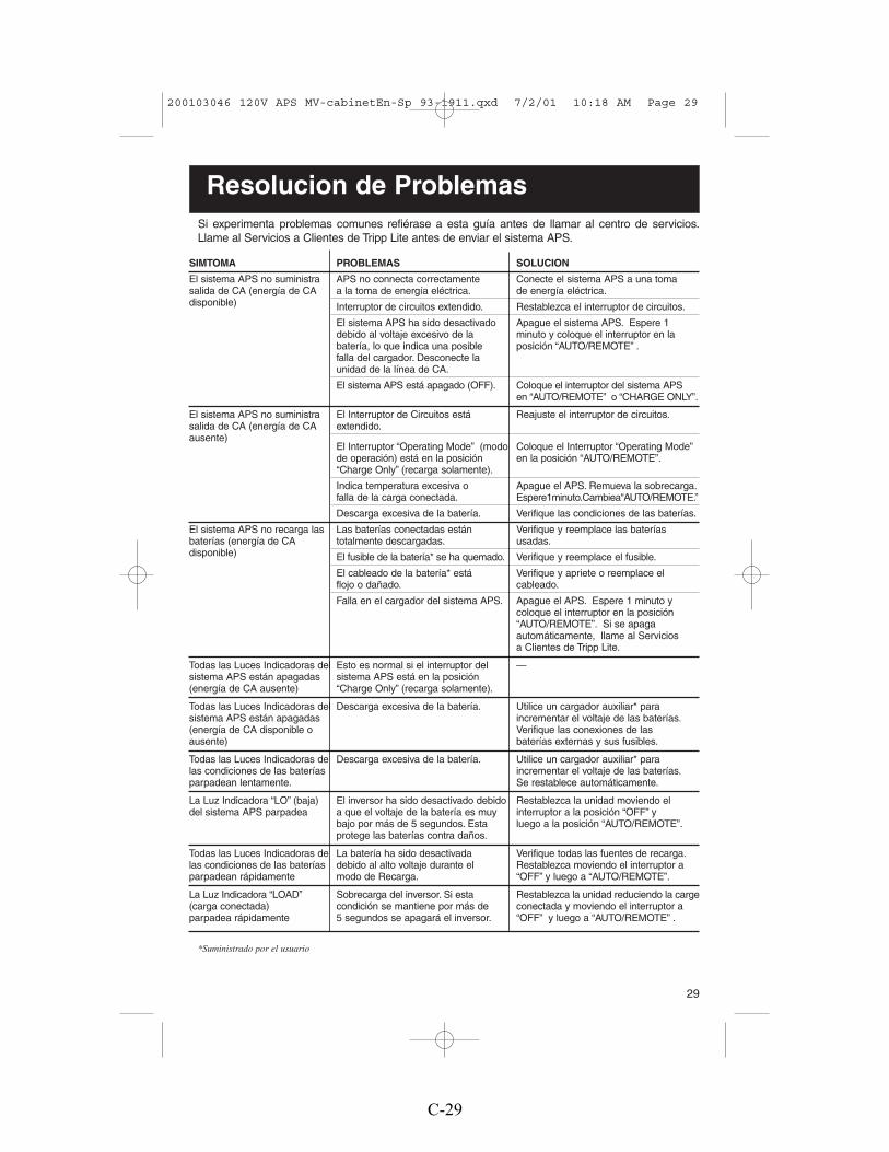
29
Si experimenta problemas comunes refiérase a esta guía antes de llamar al centro de servicios.Llame al Servicios a Clientes de Tripp Lite antes de enviar el sistema APS.
SIMTOMA PROBLEMAS SOLUCION
El sistema APS no suministra APS no connecta correctamente Conecte el sistema APS a una tomasalida de CA (energía de CA a la toma de energía eléctrica. de energía eléctrica.disponible) Interruptor de circuitos extendido. Restablezca el interruptor de circuitos.
El sistema APS ha sido desactivado Apague el sistema APS. Espere 1debido al voltaje excesivo de la minuto y coloque el interruptor en labatería, lo que indica una posible posición “AUTO/REMOTE” .falla del cargador. Desconecte la unidad de la línea de CA.
El sistema APS está apagado (OFF). Coloque el interruptor del sistema APS en “AUTO/REMOTE” o “CHARGE ONLY”.
El sistema APS no suministra El Interruptor de Circuitos está Reajuste el interruptor de circuitos.salida de CA (energía de CA extendido.ausente)
El Interruptor “Operating Mode” (modo Coloque el Interruptor “Operating Mode”de operación) está en la posición en la posición “AUTO/REMOTE”.“Charge Only” (recarga solamente).
Indica temperatura excesiva o Apague el APS. Remueva la sobrecarga.falla de la carga conectada. Espere1minuto.Cambiea“AUTO/REMOTE.”
Descarga excesiva de la batería. Verifique las condiciones de las baterías.
El sistema APS no recarga las Las baterías conectadas están Verifique y reemplace las baterías baterías (energía de CA totalmente descargadas. usadas.disponible) El fusible de la batería* se ha quemado. Verifique y reemplace el fusible.
El cableado de la batería* está Verifique y apriete o reemplace el flojo o dañado. cableado.
Falla en el cargador del sistema APS. Apague el APS. Espere 1 minuto ycoloque el interruptor en la posición “AUTO/REMOTE”. Si se apaga automáticamente, llame al Servicios a Clientes de Tripp Lite.
Todas las Luces Indicadoras del Esto es normal si el interruptor del —sistema APS están apagadas sistema APS está en la posición(energía de CA ausente) “Charge Only” (recarga solamente).
Todas las Luces Indicadoras del Descarga excesiva de la batería. Utilice un cargador auxiliar* para sistema APS están apagadas incrementar el voltaje de las baterías.(energía de CA disponible o Verifique las conexiones de lasausente) baterías externas y sus fusibles.
Todas las Luces Indicadoras de Descarga excesiva de la batería. Utilice un cargador auxiliar* para las condiciones de las baterías incrementar el voltaje de las baterías.parpadean lentamente. Se restablece automáticamente.
La Luz Indicadora “LO” (baja) El inversor ha sido desactivado debido Restablezca la unidad moviendo el del sistema APS parpadea a que el voltaje de la batería es muy interruptor a la posición “OFF” y
bajo por más de 5 segundos. Esta luego a la posición “AUTO/REMOTE”.protege las baterías contra daños.
Todas las Luces Indicadoras de La batería ha sido desactivada Verifique todas las fuentes de recarga.las condiciones de las baterías debido al alto voltaje durante el Restablezca moviendo el interruptor aparpadean rápidamente modo de Recarga. “OFF” y luego a “AUTO/REMOTE”.
La Luz Indicadora “LOAD” Sobrecarga del inversor. Si esta Restablezca la unidad reduciendo la carge (carga conectada) condición se mantiene por más de conectada y moviendo el interruptor aparpadea rápidamente 5 segundos se apagará el inversor. “OFF” y luego a “AUTO/REMOTE” .
*Suministrado por el usuario
Resolucion de Problemas
200103046 120V APS MV-cabinetEn-Sp 93-1911.qxd 7/2/01 10:18 AM Page 29
C-29

30
Especificaciones (Modelos con cable)
MODELOS CON CABLE: APS 1012 APS 1024Peso: 11.9 Kg 11.9 Kg
INVERSOREnergía continua a 20º C 900 Vatios 1000 Vatios
Energía de sobretensiones transitorias (5 segundos): 1800 Vatios 2000 Vatios
Eficiencia (Carga Completa): 90% 90%Indice Mínimo de Capacidad del Fusible: 225A 125ACorriente de Entrada de CD a Niveles Nominales
Carga Completa: 95 A 47 ASin Carga: 2.2 A* 1.3 A*
Voltios Nominales de Entrada: 12 V de CD 24 V de CDGama de Voltaje de Entrada de CD: 10 a15 V de CD 20 a 30 V de CDVoltios Nominales de Salida: 120V de CA ±5% 120V de CA ±5%Frecuencia Nominal de Salida: 60 Hz ±.3% 60 Hz ±.3%
CARGADOR DE BATERIASCapacidad de Carga de CD: 30 A 15 ALongitud Máxima del Cable: 2 pies 7 piesAceptación de Voltios de CD: Programable Programable
14.4**/14.2 V Húmeda**/Gel 28.8 V**/28.4 V Húmeda**/GelFlotador - Voltios de CD (con batería de gel): 13.3 V (13.6 V) 26.6 V (27.2 V)Voltaje de Entrada de CA: 120 V 120 VCorriente de Entrada de CA: 8 A 8 A
OPERACION EN LINEA DE CAEntrada Mínima en Voltios de CA: Programable Programable
75**, 85, 95 ó 105V de CA 75**, 85, 95 ó 105V de CAEntrada Máxima en Voltios de CA:(Continua, Cargador al Máximo) Programable 135** ó 145V de CA Programable 135** ó 145V de CACorriente Máxima de Entrada(Continua, Cargador al Máximo) 12 A 16 AFrecuencia de Entrada: 60 Hz ±10% 60 Hz ±10%Salida Máxima de CA (Continua): 8.3 A 8.3 ATiempo de Transferencia Automática: 4-5 milisegundos 4-5 milisegundos
*La sensibilidad de carga puede reducir esto a 1/30 de la corriente indicada. **Regulación de fábrica.
200103046 120V APS MV-cabinetEn-Sp 93-1911.qxd 7/2/01 10:18 AM Page 30
C-30

31
Especificaciones (Modelos con toma directa al circuito)MODELOS CON TOMA DIRECTA AL CIRCUITO: APS 2012 APS 2424Peso: 17.1 Kg 18.5 Kg
INVERSOREnergía continua a 20º C 2000 Vatios 2400 VatiosEnergía de sobretensiones transitorias (5 segundos): 4000 Vatios 4800 VatiosEficiencia (Carga Completa): 90% 90%Indice Mínimo de Capacidad del Fusible: 500A 300ACorriente de Entrada de CD a Niveles Nominales
Carga Completa: 192 A 112 ASin Carga: 2.5 A* 1.5 A*
Voltios Nominales de Entrada: 12 V de CD 24V de CDGama de Voltaje de Entrada de CD: 10 a15 V de CD 20 a 30 V de CDVoltios Nominales de Salida: 120V de CA ±5% 120V de CA ±5%Frecuencia Nominal de Salida: 60 Hz ±.3% 60 Hz ±.3%
CARGADOR DE BATERIASCapacidad de Carga de CD: 60 A 30 ALongitud Máxima del Cable: 1 pies 3 piesAceptación de Voltios de CD: Programable Programable
14.4**/14.2 V Húmeda**/Gel 28.8 V**/28.4 V Húmeda**/GelFlotador - Voltios de CD (con batería de gel): 13.3 V (13.6 V) 26.6 V (27.2 V)Voltaje de Entrada de CA: 120 V 120 VCorriente de Entrada de CA: 16 A 16 A
OPERACION EN LINEA DE CAEntrada Mínima en Voltios de CA: Programable 75**, 85, 95 ó 105V de CA Programable 75**, 85, 95 ó 105V de CAEntrada Máxima en Voltios de CA(Continua, Cargador al Máximo): Programable 135** ó 145V de CA Programable 135** ó 145V de CACorriente Máxima de Entrada(Continua, Cargador al Máximo) : 32 A 36 AFrecuencia de Entrada: 60 Hz ±10% 60 Hz ±10%Maximum Output AC (Continuous): 16.7 A 20 A
Automatic Transfer Time: 4-5 milisegundos 4-5 milisegundos
MODELOS CON TOMA DIRECTA AL CIRCUITO: APS 2448 APS 3636VRPeso: 18.5 Kg 25.6 Kg
INVERSOREnergía continua a 20º C 2400 Vatios 3600 VatiosEnergía de sobretensiones transitorias (5 segundos): 4800 Vatios 7200 VatiosEficiencia (Carga Completa): 90% 89%Indice Mínimo de Capacidad del Fusible: 300A 300ACorriente de Entrada de CD a Niveles Nominales
Carga Completa: 56 A 114 ASin Carga: 1.5 A* 1.7 A*
Voltios Nominales de Entrada: 48V de CD 36V de CDGama de Voltaje de Entrada de CD: 40 a 60 V de CD 30 a 45 V de CDVoltios Nominales de Salida: 120V de CA ±5% 120V de CA ±5%
Frecuencia Nominal de Salida: 60 Hz ±.3% 60 Hz ±.3%
CARGADOR DE BATERIASCapacidad de Carga de CD: 30 A 30 ALongitud Máxima del Cable: 12 pies 4.5 piesAceptación de Voltios de CD: Programable Programable
57.6 V**/56.8 V Húmeda**/Gel 43.2 V**/42.6 V Húmeda**/GelFlotador - Voltios de CD (con batería de gel): 53.2V (54.4 V) 39.9 V (40.8 V)Voltaje de Entrada de CA: 120 V 120 VCorriente de Entrada de CA: 16 A 24 A
OPERACION EN LINEA DE CAEntrada Mínima en Voltios de CA: Programable 75**, 85, 95 ó 105V de CA Programable 75**, 85, 95 ó 105V de CAEntrada Máxima en Voltios de CA(Continua, Cargador al Máximo): Programable 135** ó 145V de CA Programable 135** ó 145V de CACorriente Máxima de Entrada(Continua, Cargador al Máximo) : 33 A 54 A***Frecuencia de Entrada: 60 Hz ±10% 60 Hz ±10%Salida Máxima de CA (Continua): 20 A 30 A
Tiempo de Transferencia Automática: 4-5 milisegundos 4-5 milisegundos*La sensibilidad de carga puede reducir esto a 1/30 de la corriente indicada. **Regulación de fábrica.*** Cuando la regulación automática de voltaje está elevando la corriente de entrada.
200103046 120V APS MV-cabinetEn-Sp 93-1911.qxd 7/2/01 10:18 AM Page 31
C-31

32
2
Diagrams/Esquemas
3
1
See “Configuration”, pg. 5. 1.1 is DIP Switch Group A. 1.2 is DIP Switch Group B.
Refiérase a la sección “Configuración”, página 20. 1.1 representa el Grupo A de Interruptores DIP. 1.2 representael Grupo B de Interruptores DIP
See Hardwire Electrical Connections, pg. 9. 3.1 is thecover plate, 3.2 is the five-position terminal strip, 3.3 isthe output neutral (white), 3.4 is the output hot (black), 3.5is the ground (green), 3.6 is the input neutral (blue) and3.7 is the input hot (brown).
Refiérase a la sección “Conexiones Eléctricas Directas alCircuito”, página 24. 3.1 representa la cubierta;3.2 representa la barra de terminales de 5 posiciones;3.3 representa la terminal neutra de salida (blanca);3.4 representa la terminal positiva de salida (negra);3.5 representa la terminal de conexión a tierra (verde);3.6 representa la terminal neutra de entrada (azul) y 3.7 representa la terminal positiva de entrada (café).
3.2 3.1
3.7
3.6
3.33.4
3.5
1.2 1.1
200103046 120V APS MV-cabinetEn-Sp 93-1911.qxd 7/2/01 10:18 AM Page 32
C-32

33
4
5
6
X/2 VoltsX/2 Volts
6.1
X VoltsX Volts X Volts X Volts5.1
See Battery Connection, Pg.8. 4.1 is the fuse. X = Your APS's Inverter's Nominal Input Voltage. (See specs.)
Refiérase a la sección “Conexión de Baterías”, página 23. 4.1 representa el fusible. X = El Voltaje Nominal deEntrada del Inversor del APS. (Vea las especificaciones).
See Battery Connection, Pg.8. 5.1 is the fuse. X = Your APS’s Inverter's Nominal Input Voltage. (See specs.)
Refiérase a la sección “Conexión de Baterías”, página 23. 5.1 representa el fusible. X = El Voltaje Nominal deEntrada del Inversor del APS. (Vea las especificaciones).
See Battery Connection, Pg.8. 6.1 is the fuse. X = Your APS’s Inverter's Nominal Input Voltage. (See specs.)
Refiérase a la sección “Conexión de Baterías”, página 23. 6.1 representa el fusible. X = El Voltaje Nominal deEntrada del Inversor del APS. (Vea las especificaciones).
4.1X Volts
APS
APS
APS
200103046 120V APS MV-cabinetEn-Sp 93-1911.qxd 7/2/01 10:18 AM Page 33
C-33

34
7
7.4
7.1
7.3
12V
8.68.1
8.3
8.4
12V
8.2 8.3
8.5
12V
8
7.2
Basic 12VDC Vehicular Battery Connection. See Pg.8.7.1 is the alternator. 7.2 is the vehicle battery ground. 7.3 is the vehicle battery. 7.4 is the fuse.
Conexión Básica de Baterías de 12V de CD en Vehículos. Vea página 23.7.1 representa el alternador. 7.2 representa la conexión a tierra de la batería del vehículo.7.3 representa la batería del vehículo. 7.4 representa el fusible.
Advanced 12VDC Vehicular Battery Connection. See Pg.8.8.1 is the alternator. 8.2 is a battery isolator. 8.3 is the vehicle battery ground. 8.4 is anauxiliary vehicle battery. 8.5 is the vehicle battery. 8.6 is the fuse.
Conexión Avanzada de Baterías de 12V de CD en Vehículos. Vea página 23.8.1 representa el alternador. 8.2 representa el aislador de la batería. 8.3 representa laconexión a tierra de la batería. 8.4 representa la batería auxiliar del vehículo.8.5 representa la baterÍa del vehiculo. 8.6 representa el fusible.
APS
APS
200103046 120V APS MV-cabinetEn-Sp 93-1911.qxd 7/2/01 10:18 AM Page 34
C-34

35
1. Interruptor “Operating Mode”(Modo de operación)
2. Grupo A de Interruptores DIP(Todos los modelos)
3. Grupo B de Interruptores DIP(Modelos selectos únicamente)
4. “LINE” (Línea) (Todos los modelos)
5. “INV” (Inversor )(Todos los modelos)
6. “LOAD” (Carga Conectada)
7. “CUT/BOOST” (disminuyendo / elevando) (Modelos VR solamente)
8. “BATTERY HI/MED/LO”(Carga de Baterías Alta/Media/Baja) (Todos los modelos)
9. Terminales de Entrada de CD (Todos los modelos)
10. Receptáculos de CA(Solamente en los modelos con cable de CA)
11. Cable de Línea de CA(Solamente en los modelos con cable de CA)
12. Barra de Terminales de Toma Directa a Entrada/Salidade CA (Modelos con toma directa al circuito solamente)
13. Interruptores de Circuito con Restablecimiento
14. Conector para el Módulo de Control Remoto (Todos los modelos)
15. Potenciómetro Sensor de Carga Conectada (Todos los modelos)
9
3
15
6 1
13
541482
12
9
11
13
15
16541482
109
7
1. Operating Mode Switch (All models)
2. DIP Switch Group A (All models)
3. DIP Switch Group B (Select models only)
4. “LINE” (All models)
5. “INV” (Inverting—all models)
6. “LOAD” (All models)
7. “CUT/BOOST” (VR models only)
8. “BATTERY HI/MED/LO” (All models)
9. DC Input Terminals (All models)
10. AC Receptacles (Corded models only)
11. Fixed AC Input Line Cord fixed (Corded models only)
12. AC Input/Output Terminal Strip (Hardwire models only)
13. Resettable Circuit Breakers (All models)
14. Remote Module Connector (All models)
15. Load Sense Potentiometer (All models)
B. Hardwired ModelModelo con Toma Directa al Circuito
A. Corded ModelModelo con Cable
16
200103046 120V APS MV-cabinetEn-Sp 93-1911.qxd 7/2/01 10:18 AM Page 35
C-35

36
93-1911 (200103046)
1111 W. 35th StreetChicago, IL 60609 USA
Customer Support: (773) 869-1234www.tripplite.com
200103046 120V APS MV-cabinetEn-Sp 93-1911.qxd 7/2/01 10:18 AM Page 36
C-36

APPENDIX D
Atlas Micro Hydraulic Jackplate Instruction Manual

ATLAS MICRO™
Hydraulic Jack Plate
Installation Instructions Model: AHJM-4
1. If no outboard engine is mounted to transom skip to step 62. If outboard is mounted to transom, consult your dealer or motor manual for proper
lifting device for your engine.3. Attach lifting device to outboard according to engine manual.
4. Remove mounting nuts and swing motor away from boat. Use caution not to damage wires orcables.
5. Most cables and wires are of sufficient length to allow Jack Plate installation withoutdisconnecting but some may require this step.
6. Mount Atlas Micro™ plate onto the transom using the four mounting bolts that came with theengine.
7. It is recommended when possible to insert bolts from inside the Atlas Micro™ plate through thetransom and use a flat washer and lock washer before the nut.If nuts are pulling into the transom use our TSP-1 Transom Support Plate.
8. Select the proper mounting hole on your engine according to your situation and mount to AtlasMicro™ using four ½”-13 x 3” stainless steel bolts, flat washers, and lock washers. You may usea jack plate bolt kit such as our BK-1.
9. Select a location for your up-down switch. Drill a ½” hole and mount switch.
10. Locate three wires on the wiring harness. Attach the blue “UP” wire to the top post on the switch,the green “DOWN” wire to the bottom post and the purple “12V” hot wire to the center post.
11. Connect the black and white wires coming from the actuator to the green and blue wires of thewire harness with the attached Packard connectors.
12. Route the wires from the Atlas Micro™ motor so that they will not be damaged during the up &down operation of the jack plate.CAUTION: Select a dry location for the relays and securely mount there.
13. Locate the red ring terminal marked “POS” and connect to the positive (+) post of your battery.Locate the black “NEG” ring terminal and connect to the negative (-) post of the battery. LocatePurple wire with the in-line fuse and connect to any hot source.
D-1

MAINTENANCE INSTRUCTIONS
SERVICING
The Atlas Micro™ is equipped with a high speed hydraulic actuator that is factory tested and comes filled with the proper level of fluid. However, if it becomes necessary to add fluid use ISO100 hydraulic fluid or SAE 20/30 non detergent oil. Follow these steps for servicing the reservoir. (See Fig. 1)
1. Raise the Atlas Micro™ all the way up.2. Remove the 1/8” “Filler” plug using a 3/16” hex (allen) wrench.3. Remove the 1/8” “Level” plug with the same wrench4. Pour fluid into the “Filler” hole until it runs out of the “Level” hole.5. Run the Atlas Micro™ all the way down then all the way up again.6. Top off with fluid, replace the “Level” plug and the “Filler” plug.
Fig. 1
Emergency Relief Valve
In the event the pump fails to allow the Hydro-Jacker™ to be lowered you may release the pressure from the actuator and lower the engine.
CAUTION: RELEIVING THIS PRESSURE WILL CAUSE ENGINE TO FALL RAPIDLY. SUPPORT ENGINE WITH A FLOOR JACK OR HOIST BEFORE RELEASING VALVE. THEN LOWER ENGINE WITH JACK TO BOTTOM POSITION. (See Fig. 2) 1. Locate relief valve on bottom of actuator pump (1/4” hex screw).2. Slowly turn the screw counter clockwise ½ to 1 full turn.
Fig. 2
D-2

Hydraulic Actuator Removal (See Fig. 3) 1. Lock the four ¾” side roller bolts down to 60 ft/lbs.2. Tap the bottom locking pin out using a hammer and ½” dia. driver bar. (See Fig. 3)3. Remove the top pin by removing the ½” lock nut and sliding out the 9” stainless bolt. (See Fig. 4)4. Pull the actuator upward to remove the ram from the bottom bracket.5. Caution: After replacing actuator be sure to loosen four side bolts until the washers can be rotated by hand.
Fig. 3
Fig. 4
D-3

Atlas™ Micro Jacker Dimensions Transom Side View
D-4