robotic soldering systems -...
TRANSCRIPT

1
Robotic Soldering Solutions
Exclusive Distributor in North America for Japan UNIX

Perfect soldering every time with reduced
labor costs!
2

3
Solutions Offered:
• Contact Soldering-most common
• Ultrasonic Soldering
• Non-contact Soldering:
• Laser Soldering
• Microflame Soldering
Each has it’s place and price point!

4
Contact Soldering
How it can help you
- Operators doing difficult hand soldering with high labor costs-Soldering quality problems, throughput too low or inconsistent results-An existing robotic system that may need replacing-wearing out, poor results, lack of factory support-Selective soldering that can’t be easily done with typical bottom side selective soldering systems-Post wave or reflow hand soldering that is better done with a robot
5
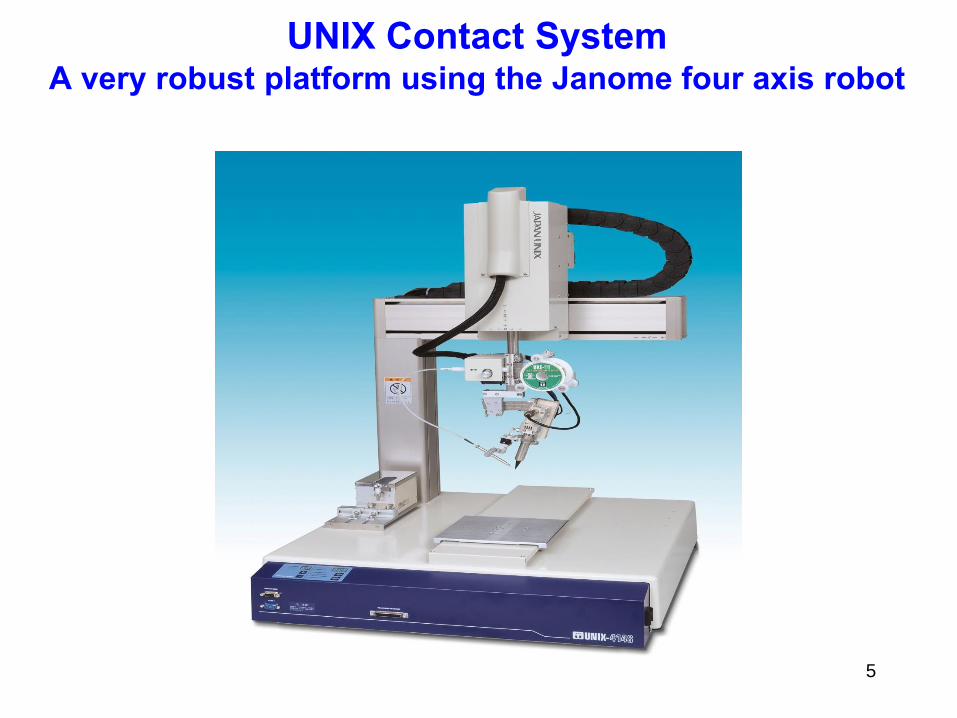
UNIX Contact SystemA very robust platform using the Janome four axis robot

6
Multi-Articulated Six Axis Robot #700V
• Works like a human arm and hand• Much larger working area than a desktop• Ideal for in-line automation• 5300mm/sec max. velocity

7
700V Multi-Articulated Soldering Robot

SCARA Robot #700H
8
• 5 Axis• Increased reach for large working area• 7128mm/sec max. velocity• Three models with max. reach radius of350, 450 and 550mm

In-Line Contact System
9

10
31 Fairfield Place West Caldwell, NJ 07006 Ph. 973-575-0610 Fx. 973-575-9234 www.fancort.com
UNIX CONTACT SOLDERING “FAB” SHEET
Features Advantages Benefits1. Soldering head can do
point-to-point and line
soldering
1.1 No need to purchase two
different soldering heads
1.1 Save money and save
time with simple
changeover
2. Solid core solder tips retain
heat from point to point
2.1 Faster cycle time 2.1 Lower costs of operation
per assembly
3. Scale and tooling pins to
accurately realign solder
head and feeder
3.1 Changeover from line
soldering to point to point is
easy and accurate
3.1 Save time in setups and
eliminate costly errors
4. Program up to 63 soldering
conditions
4.1 Reduces the need to create
separate programs for different
conditions on one assembly
4.1 Increased throughput
5. Standard 200W heater with
built-in thermocouple;
optional 300W
5.1 Heats up and recovers
faster than 100W heaters
5.1 More throughput
6. Unit section of heater block
easily removed to speed up
tip and heater replacement
times
6.1 Save time 6.1 Save money
7. Graduated angle setter is
standard
7.1 Solder feed position is
perfectly reproduced each time
you return to a setup
7.1 Saves time; improves
consistency
8. Easy to program soldering
profiles on teach pendant
8.1 Only one device needed for
all programming
8.1 Simplicity!
9. Several alarms standard
including out of solder,
solder jamming and heater
alarm
9.1 Prevents mistakes and
saves time
9.1Save money in reduced
rework
10. Three axis tip position
correction mechanism.
10.1 Automatically corrects
misalignment after replacing tip
10.1 Save money in
eliminating missed solder joints
11. Solder wire preheater to
reduce heat shocking that
results in solder balls
11.1 Maintains consistent solder
quality
1.1 Reduce rework; save
money
12. Needle swing mechanism
allows solder feeder needle to
swing away from tip
automatically
12.1 Allows clearance for easier
tip cleaning, access to tight areas
and easier to program
12.1 Save time, avoid solder
errors
13. Solder tips have 500
microns of iron plating versus
competition with 250-300
13.1 Longer life of tips; less
changeover time lost
13.1 Save money
14. Optional nitrogen generator 14.1 Prevents oxidation of tips
and produces better flow or
wetting
14.1 Higher quality and less
maintenance

11
Point to Point Example of wires
soldered to ceramic substrate

12
Slide Soldering Post Reflow of Connector

13
Point to Point on LCD

14
Medical Device Co. Small wires on substrate

15
LED Through-Hole post Reflow

16
Two Wires Soldered to Small Piezoelectric Battery

17
Automotive, Two Areas, Point to Point

Contract Manufacturer with Medical Application
18
•Twenty up fixture to solder two wires from a battery to pads on aflex circuit•Used a UNIX414R desktop with N2
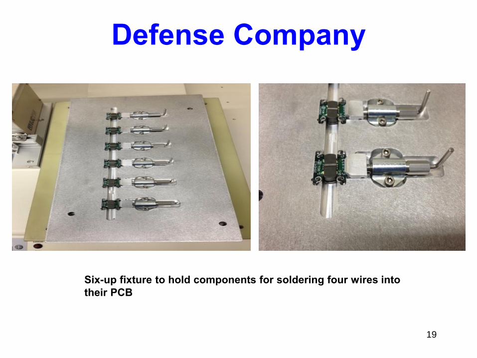
Defense Company
19
Six-up fixture to hold components for soldering four wires into their PCB

Fixture with heater plate
20
Project required preheating this multi-layer PCB in order to solder some ceramic components. Insulator is underneath the heater plate to protect the robot

Complex Fixture for OEM
21
•Four step solderingprocess with four subassemblies•Rotating member to solderboth sides of the PCB•Order was won from lessexpensive competitor because of fixture design

Four step soldering project
22
Customer had many operators assembling the four components shown on the left. Fancort fixture and robot allowed them to reduce the number of operators and dramatically reduce rework:1. Plastic housing is placed on the post on the right side of the fixture and first
PCB is dropped over four pins. Program one is run to solder these four pinsto the PCB
2. Second PCB is inserted into the fixture at right angles to the first PCB andthe second program is run to solder one side of the PCB to the second PCB
3. Fixture is rotated so the other side of the second PCB can be soldered to thefirst side.
4. Two wires are inserted into the fixture under a spring-loaded holder to retainthe wires to pads on the second PCB and the fourth program is run.
5. Fixture holds five of these assemblies.

23
Laser Soldering

24
Why Laser Soldering?
• Extremely small points of soldering without the need for contact:minimum spot size available is 0.2mm
• Intense heat required that can’t be done with contact soldering;20W to 75W laser diode
• Cycle time usually shorter than contact
• No consumables
• Typically higher volume applications
• Feed wire as small as 0.2mm or solder using paste
• Less diffuse heat generation than contact soldering
• Heating time is instantaneous
• Develop multiple profiles in one program
• Stand-alone or in-line systems or we can supply modules foryou to integrate into your own cell
25
Laser Diode Soldering Background Information
• UNIX is the leader in laser soldering systemswith the most installations in the worldprimarily in Asia
• Fancort has a laser system in NJ withdifferent wattage diodes and fibers forsampling your parts including 0.2mm spotsize which is the smallest
• Fancort can deliver a turnkey systemincluding fixtures for any application

26
Stand-Alone Laser System
w/Enclosure

27
31 Fairfield Place West Caldwell, NJ 07006 Ph. 973-575-0610 Fx. 973-575-9234 www.fancort.com
UNIX LASER SOLDERING “FAB” SHEET
Features Advantages Benefits
1. CCD camera built into the
laser head
1.1 Makes programming
much easier and more accurate
1.1 Save money and save
time with simple changeover
2. Custom shapes for moreprecise spot of heat eg.oval, doughnut, triangle,
square, rectangle, etc.
2.1 Heat transfer is reduced to surroundingcomponents
2.1 Less risk to damage nearby components
3. Spot size to 0.2mm versus0.4mm for competition
3.1 Tighter area for soldering of smaller
components and less heat transfer to other areas
3.1 More accurate; less chance of damaging
nearby components
4. Clear glass over standardlens
4.1 Reduces risk of damaging expensive laser lens
4.1 Saves money and lenslife
5. Average mean time of20,000 hours of life
5.1 Reduces cost ofownership
5.1 Better ROI
6. Special feeder to handle0.15mm solder versus0.3mm for competition
6.1 Solder smaller parts 6.1 More flexibility
7. Laser built by UNIX andintegrated; competition
buys and resells
7.1 Better support and newer technologies and features
7.1 Better value for your money

In-Line Laser System
28

Interior of In-Line Laser
29

30
UNIX Ultrasonic Soldering
• Primary applications are soldering on glass which is used in thesolar cell manufacturing industry, soldering on copper, aluminumor other metal surfaces that conventional soldering is not aseffective
• The principle behind ultrasonic soldering is high-frequencyultrasonic vibrations that promote removal of the dirt on the basematerial, or reducing oxide films, diffusing metals, removing airbubbles, etc. This leads to improvement in wettability andspreadability of the solder producing better joints and reducingtack time
• UNIX is ahead of the competition in this technology and can dosampling in Japan.
• The technology is available in a manual station (next slide) andintegrated to a robotic system.
• No need for flux

31
Ultrasonic Soldering
• Controller Hand Held Iron

32
Microflame Soldering
-More heat is required to make a connection than conventional contactsoldering can achieve
-Extremely small point of contact; flames can be much smaller than the smallest soldering iron tip
-Very fast cycle time; typically 1-2 seconds per solder joint-Applications can be found in the industrial market as well as electronic
manufacturers-Fancort is an authorized Spirflame integrator, a leader in microflame
technology

33
Fancort Delivered Custom Spirflame System
for Soldering Cord Sets
• Processes 260 cord sets per hour

34
Cord Sets with different gauge wires were done
on the same machine
The application required more heat than
contact soldering could provide

35
Manual Microflame System
• Stand-alone system with generator, flame, solder feeder andcontroller
• Flame is driven in Z motion by cylinder; solder feeder must beaccurately positioned; operator uses a fixture to hold the workand steps on the foot switch, flame comes down, feeder feedswire to programmed amount, and soldering is done very quickly.
• Ideal for development work or manual soldering where microflamefits the application
• Cost is approximately $25K• Easy to use and very safe

36
Microflame or Contact?Application was to solder two reed switches into thiscoil with minimal stress to protect glass seals
Decided on contact soldering w/UNIX
Arrows to point of contact

37
Thank You
• For further information, or to discuss a specificapplication, contact Yolanda Figueroa at973-575-0610 x238 or by email at:[email protected]
• Please visit our website for other videos andmore technical information; www.fancort.com