robotic/automatic tool changer - ati industrial …robotic/automatic tool changer quick-change...
TRANSCRIPT

Robotic/Automatic Tool ChangerQuick-Change Standard and Heavy Automation Series
2 VISIT WWW.ATI-IA.COM FOR CURRENT PRODUCT SPECIFICATIONS, 2-D DRAWINGS, AND 3-D CAD MODELS
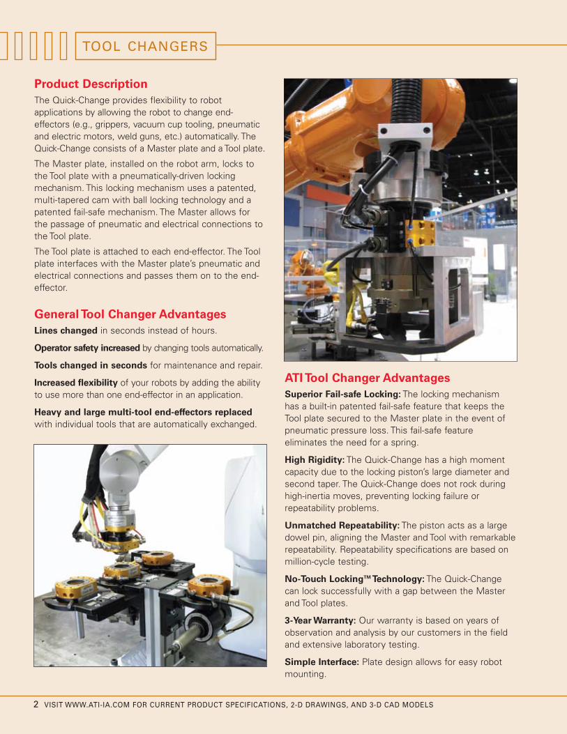
Product DescriptionThe Quick-Change provides flexibility to robotapplications by allowing the robot to change end-effectors (e.g., grippers, vacuum cup tooling, pneumaticand electric motors, weld guns, etc.) automatically. TheQuick-Change consists of a Master plate and a Tool plate.
The Master plate, installed on the robot arm, locks tothe Tool plate with a pneumatically-driven lockingmechanism. This locking mechanism uses a patented,multi-tapered cam with ball locking technology and apatented fail-safe mechanism. The Master allows forthe passage of pneumatic and electrical connections tothe Tool plate.
The Tool plate is attached to each end-effector. The Toolplate interfaces with the Master plate’s pneumatic andelectrical connections and passes them on to the end-effector.
General Tool Changer AdvantagesLines changed in seconds instead of hours.
Operator safety increased by changing tools automatically.
Tools changed in seconds for maintenance and repair.
Increased flexibility of your robots by adding the abilityto use more than one end-effector in an application.
Heavy and large multi-tool end-effectors replacedwith individual tools that are automatically exchanged.
ATI Tool Changer AdvantagesSuperior Fail-safe Locking: The locking mechanismhas a built-in patented fail-safe feature that keeps theTool plate secured to the Master plate in the event ofpneumatic pressure loss. This fail-safe featureeliminates the need for a spring.
High Rigidity: The Quick-Change has a high momentcapacity due to the locking piston’s large diameter andsecond taper. The Quick-Change does not rock duringhigh-inertia moves, preventing locking failure orrepeatability problems.
Unmatched Repeatability: The piston acts as a largedowel pin, aligning the Master and Tool with remarkablerepeatability. Repeatability specifications are based onmillion-cycle testing.
No-Touch LockingTM Technology: The Quick-Changecan lock successfully with a gap between the Masterand Tool plates.
3-Year Warranty: Our warranty is based on years ofobservation and analysis by our customers in the fieldand extensive laboratory testing.
Simple Interface: Plate design allows for easy robotmounting.
TOOL CHANGERS

VISIT WWW.ATI-IA.COM FOR CURRENT PRODUCT SPECIFICATIONS, 2-D DRAWINGS, AND 3-D CAD MODELS 3
“It is highly recommended that ATI’s Tool Changer beconsidered when looking at any kind of automatic tooldisconnect or application using this type of design.”
Joe MitoryASME Project Manager
Table of Contents
Quick-Change Locking Mechanism . . . . . . . . . . . . .5Quick-View Specification Table . . . . . . . . . . . . . . . .6Model Selection . . . . . . . . . . . . . . . . . . . . . . . . . . .7Module Selection . . . . . . . . . . . . . . . . . . . . . . . . . .8QC-5 . . . . . . . . . . . . . . . . . . . . . . . . . . . . . . . . . . .10QC-11 . . . . . . . . . . . . . . . . . . . . . . . . . . . . . . . . . .12QC-20 . . . . . . . . . . . . . . . . . . . . . . . . . . . . . . . . . .14QC-21 . . . . . . . . . . . . . . . . . . . . . . . . . . . . . . . . . .16Tool Stands for QC-5 to QC-21 . . . . . . . . . . . . . .18QC-40 . . . . . . . . . . . . . . . . . . . . . . . . . . . . . . . . . .20QC-41 . . . . . . . . . . . . . . . . . . . . . . . . . . . . . . . . . .22QC-60 . . . . . . . . . . . . . . . . . . . . . . . . . . . . . . . . . .24QC-71 . . . . . . . . . . . . . . . . . . . . . . . . . . . . . . . . . .26QC-110 . . . . . . . . . . . . . . . . . . . . . . . . . . . . . . . . .28QC-150 . . . . . . . . . . . . . . . . . . . . . . . . . . . . . . . . .30Tool Stands for QC-40 to QC-150 . . . . . . . . . . . .32Sensor Interface Plate System . . . . . . . . . . . . . . .34QC-300 . . . . . . . . . . . . . . . . . . . . . . . . . . . . . . . . .36Standard Series Modules and Options . . . . . . . . .38
Quick-Change Family (left to right from back row; Master plate is standing, Tool plate is lying flat directly in front of each Master plate or to theright); QC-150; QC-210; QC-110; Middle row: QC-71; QC-60; QC-41; Front row: QC-40; QC-5; QC-11; QC-20.
Tool Changers for Heavy Automation . . . . . . . . . . .42QC-210 . . . . . . . . . . . . . . . . . . . . . . . . . . . . . . . . . .44QC-310 . . . . . . . . . . . . . . . . . . . . . . . . . . . . . . . . . .46QC-510 . . . . . . . . . . . . . . . . . . . . . . . . . . . . . . . . . .48How To Order QC-210 to QC-510 . . . . . . . . . . . . . .50Tool Stands for QC-210 to QC-510 . . . . . . . . . . . . .51QC-1210 . . . . . . . . . . . . . . . . . . . . . . . . . . . . . . . . . .54Heavy Automation Series Modules and Options . .56Tool Changer Accessories . . . . . . . . . . . . . . . . . . . .62Utility Couplers . . . . . . . . . . . . . . . . . . . . . . . . . . . .63Special Application Tool Changers . . . . . . . . . . . . . .66

4 VISIT WWW.ATI-IA.COM FOR CURRENT PRODUCT SPECIFICATIONS, 2-D DRAWINGS, AND 3-D CAD MODELS
TOOL CHANGERS
Quick-Change Tool Changers
ATI provides two distinct series of its line of Quick-Change Tool Changers: Standard and HeavyAutomation. Both feature similar functioning lockingmechanisms, but they have different body designs andpayload abilities to best suit specific applications.
Standard Series Tool Changers
From the lightest duty to the heaviest duty payloadrange, the Quick-Change Standard Series Tool Changerstypically feature round bodies with an array ofintegrated pneumatic ports.
This style results in a compact, economical toolingarrangement where a majority of the applications savemoney and space by utilizing the built-in ports.However, even for applications where additionalelectrical signals or other utilities need to be coupled,the Standard Series Tool Changers feature one or twoadditional utility module mounting flats.
Additional options for Standard Series Tool Changersinclude a Sensor Interface Plate (combined adapterplate and sensor pack for Lock and Unlock status), basicInterface Plates, and modular, highly-customizable ToolStorage Stand arrangements.
Heavy Automation Tool Changers
The Heavy Automation Series Tool Changers featuresimple, compact, square Tool Changer bodies designedfor heavy-duty applications (e.g., welding). Instead ofintegrated pneumatic ports, the area of the body ismaximized for fitting the largest, strongest lockingmechanism possible. Each Tool Changer features built inLock/Unlock/Ready-to-Lock sensors, as well as heavy-duty alignment pins. The square shape allows formounting four or more utility modules to passpneumatics, fluid, electrical, fiber optic, weld current, andmore. This unique series of heavy-duty Tool Changers isalso compatible with an economical Tool Stand familythat includes compliant drop-off points, Tool Shields, anda highly-customizable array of configurations.

VISIT WWW.ATI-IA.COM FOR CURRENT PRODUCT SPECIFICATIONS, 2-D DRAWINGS, AND 3-D CAD MODELS 5
Interface plate
Piston
Lock air pressure pushes thepiston down, driving the balls outand under the bearing race ring,pulling up the Tool plate.
The Tool plate will not releasefrom the Master plate unlessunlock air pressure is applied.
Figure 1: Tool Changer in unlockedposition
Figure 2b: Section view of Tool Changerin Ready-to-Lock position(interface plate not shown)
Our patented locking mechanism andunique fail-safe feature have been inindustrial use for more than fifteenyears without failure.
Our No-Touch Locking technologyallows plate separation when locking.
Figure 3b: Section view of Tool Changerin locked position
Figure 4b: Section view of Tool Changerin fail-safe position
*Video available on website.
Master plate
Electrical module (Master-side)
Male coupling
Tool plate
Electrical module (Tool-side)
Bearing race
No-Touch Locking
Cam
Hardened steel ball is on the first taper of the cam.
1st taper allows Master andTool to be separate while
locking.
Figure 2a: Close--up of locking ballposition with Tool Changer inReady-to-Lock position
Hardened steel ball is on thesecond taper of the cam for
high repeatability and strength.
Figure 3a: Close-up of locking ballin locked position
Fail-safe conical surface(reverse taper)
First taper
Hardened steel ball is on fail-safe conical surface.
(reverse taper) In the event lock air pressure
is removed, the balls aretrapped by the cam.
The fail-safe prevents thecam and piston from moving
due to gravity, vibration oracceleration.
Figure 4a: Close-up of locking ballwhile in fail-safe position
QUICK-CHANGE LOCKING MECHANISM
Our patented fail-safe locking mechanism features a unique multi-
tapered cam for superior reliability, repeatability, strength, and safety.
1st taper(pick-up)
2nd taper(locked)
3rd taper(fail-safe)
Bearing race
6 VISIT WWW.ATI-IA.COM FOR CURRENT PRODUCT SPECIFICATIONS, 2-D DRAWINGS, AND 3-D CAD MODELS
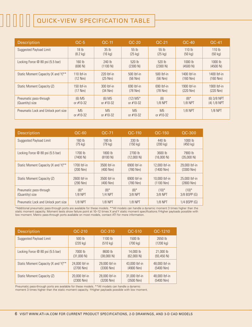
*Additional pneumatic pass-through ports are available for these models. **All models can handle a dynamic moment 3 times higher than thestatic moment capacity. Moment tests show failure point at 10–12 times X and Y static moment specifications.†Higher payloads possible withlow moment. Metric pass-through ports available on most models, contact ATI for more information.
Description QC-5 QC-11 QC-20 QC-21 QC-40 QC-41
Suggested Payload Limit 18 lb 35 lb 55 lb 55 lb 110 lb 110 lb(8.2 kg) (16 kg) (25 kg) (25 kg) (50 kg) (50 kg)
Locking Force @ 80 psi (5.5 bar) 160 lb 240 lb 520 lb 520 lb 1000 lb 1000 lb(690 N) (1100 N) (2300 N) (2300 N) (4500 N) (4500 N)
Static Moment Capacity (X and Y)** 110 lbf-in 220 lbf-in 500 lbf-in 500 lbf-in 1400 lbf-in 1400 lbf-in(12 Nm) (25 Nm) (56 Nm) (56 Nm) (160 Nm) (160 Nm)
Static Moment Capacity (Z) 150 lbf-in 300 lbf-in 690 lbf-in 690 lbf-in 1900 lbf-in 1900 lbf-in(17 Nm) (34 Nm) (78 Nm) (78 Nm) (220 Nm) (220 Nm)
Pneumatic pass-through (6) M5 (6) M5 (12) M5* (8) (8)* (6) 3/8 NPT(Quantity) size or #10-32 or #10-32 or #10-32 1/8 NPT 1/8 NPT (4) 1/8 NPT
Pneumatic Lock and Unlock port size M5 M5 M5 M5 1/8 NPT 1/8 NPTor #10-32 or #10-32 or #10-32 or #10-32
Description QC-210 QC-310 QC-510 QC-1210
Suggested Payload Limit 500 lb 1100 lb 1500 lb 2650 lb(220 kg) (510 kg) (700 kg) (1200 kg)
Locking Force @ 80 psi (5.5 bar) 7000 lb 8600 lb 14,000 lb 21,000 lb(31,000 N) (38,000 N) (62,000 N) (93,450 N)
Static Moment Capacity (X and Y)** 24,000 lbf-in 29,000 lbf-in 43,000 lbf-in 48,000 lbf-in (2700 Nm) (3300 Nm) (4900 Nm) (5400 Nm)
Static Moment Capacity (Z) 20,000 lbf-in 28,000 lbf-in 31,000 lbf-in 48,000 lbf-in(2300 Nm) (3200 Nm) (3500 Nm) (5400 Nm)
QUICK-VIEW SPECIFICATION TABLE
Description QC-60 QC-71 QC-110 QC-150 QC-300
Suggested Payload Limit 160 lb 180 lb 330 lb 440 lb 1000 lb(75 kg) (79 kg) (150 kg) (200 kg) (450 kg)
Locking Force @ 80 psi (5.5 bar) 1700 lb 1800 lb 2700 lb 3600 lb 7900 lb(7400 N) (8100 N) (12,000 N) (16,000 N) (35,000 N)
Static Moment Capacity (X and Y)** 1700 lbf-in 3500 lbf-in 6900 lbf-in 12,000 lbf-in 29,000 lbf-in(200 Nm) (400 Nm) (780 Nm) (1400 Nm) (3300 Nm)
Static Moment Capacity (Z) 2600 lbf-in 3500 lbf-in 6900 lbf-in 10,000 lbf-in 25,000 lbf-in(290 Nm) (400 Nm) (780 Nm) (1100 Nm) (2800 Nm)
Pneumatic pass-through (8)* (8)* (8)* (10)* (10)*(Quantity) size 1/8 NPT 1/4 NPT 3/8 NPT 3/8 NPT 3/8 BSPP (G)
Pneumatic Lock and Unlock port size 1/8 NPT 1/8 NPT 1/8 NPT 1/8 NPT 1/4 BSPP (G)
Pneumatic pass-through ports are available for these models. **All models can handle a dynamicmoment 3 times higher than the static moment capacity. †Higher payloads possible with low moment.

VISIT WWW.ATI-IA.COM FOR CURRENT PRODUCT SPECIFICATIONS, 2-D DRAWINGS, AND 3-D CAD MODELS 7
MODEL SELECTION
How to Select a Robotic Tool Changer
1. Sizing - Fast method: If the expected momentexerted on the Tool Changer is low or moderate, selecta Quick-Change model with a payload rating similar tothat of your robot. If the expected moment is high, or ifyou prefer to use a QC model better suited to theapplication, see the next section below.
More exact method: Moment capacity is a criticalfactor in selecting the proper Quick-Change model. Usethe following to approximate the worst-case moment:
• Find the approximate center-of-gravity (CG) of theheaviest end-effector to be used.
• Calculate the distance (D) from the CG to thebottom of the Tool plate (example below).
• Calculate the weight (W) of the heaviest end-effector.
• Multiply W by D to get an approximate staticmoment (M) (or a moment based on one G ofacceleration).
• Select a Quick-Change with a moment capacityequal to or greater than M.
Robots may produce moments two-to-three times higherthan M due to their potentially high acceleration. TheQuick-Change models are designed to handle dynamicmoments three times higher than their static momentratings.
2. Pneumatic and Electrical: Determine the number andsize of pneumatic ports and electrical contacts needed.Larger Quick-Change models have a greater number ofpneumatic ports and electrical contacts.
3.Temperature and Chemicals: The Quick-Changeuses nitrile bushings to pass pneumatics to the Toolplate, and Buna-N O-rings to seal the pneumatic lockingmechanism. Not only is this rubber material resistant tomost chemicals, it is able to withstand temperaturesranging from -20°F to 150°F. Please contact your ATIAccount Manager for information regardingtemperatures or chemicals for particular environments.
4. Precision Applications: Be sure to refer to thespecifications when dealing with applications that requirehigh repeatability.
Remember: A Tool Changer affects robot momentcapacity, payload, size, and repeatability. Forcomparable payloads, the Quick-Change is designed toexceed the robot’s specifications. Contact your ATIAccount Manager for more information.
D3
D2
My = W * D3 (Tool Changer Separation Force)
Static Moment & Torsion:Mz = W * D2 (Torsion)Mx = W * D1 (Tool Changer Separation Force)
-X
+X
W +Z
Center ofGravity
-X
-Y
-X+Z
+X
+Y
Origin
Tool
Robot Interface
+ZTooling
+Y
W
Plate
Master
Robot Arm
Center ofGravity
-Y
D1
+X
+Y
Center ofGravity
W
Z

8 VISIT WWW.ATI-IA.COM FOR CURRENT PRODUCT SPECIFICATIONS, 2-D DRAWINGS, AND 3-D CAD MODELS
MODULE SELECTION
How to Select a Module
The flexibility of our Quick-Change Tool Changers is due inpart to the large number of utility modules that are availablefor passing pneumatics, water, power, electrical signals,and more. The following is a list of considerations whentrying to determine what module you may need. Refer topages 38–41 for a list of Standard Series Tool ChangerModules and pages 56–61 for a list of Heavy AutomationTool Changer Modules.
Common Considerations for all Modules
General Considerations
There are many considerations that are applicable to all ofour utility modules. Use these as a starting point:
• Environment: Depending on the applicationenvironment, Ingress Protection (IP) may be needed.Contact ATI if solvents will be used around theapplication or if protection higher than IP65 is needed.Uncoupled modules are subject to debris; care shouldbe taken to protect exposed contacts and connections.
• Tool Changer Size: Certain modules are onlycompatible with specific Tool Changer models. Havingsome flexibility in your Tool Changer model size willincrease the number of available modules. Mostmodules are meant to be mounted on a Tool Changer.ATI also has modules available for non-Tool Changerapplications. Contact ATI for more information.
Electrical Signals
• Ingress Protection (IP): Many of our electric modulesare sealed to protect the contacts against dust andmoisture (IP65-rated) when coupled.
• Connection Type: Determine what type of connector orconnection is needed. We offer a variety of connectionoptions, such as Miniature MS quick-disconnect, D-sub,threaded, and cable-ready.
• Connector Direction: ATI offers connectors in straight,right-angle, and multi-position orientations toaccommodate special dress packages.
• Amperage and Voltage: Determine what maximumamperage and voltage rating is needed.
• Number of Pins: Determine the number of pinsrequired to pass the signals.
• Tool-ID Available: Some of our electric modules have atool-ID option available to distinguish between differenttools that are being used.

VISIT WWW.ATI-IA.COM FOR CURRENT PRODUCT SPECIFICATIONS, 2-D DRAWINGS, AND 3-D CAD MODELS 9
Pneumatics
ATI offers self-sealing port versions of most of ourpneumatic pass-through modules. Contact ATI for moreinformation or visit www.ati-ia.com for a complete listof available modules.
• Number of Pass-Through Connections:
Determine the number of pneumatic pass-throughconnections needed. Many of our Tool Changermodels have additional pass-through ports in thebody of the Tool Changer.
• Port Size: Determine what port size and threadstandard is needed.
Contact ATI if your air pressure requirements aregreater than 150 psi.
Fluid
All ATI fluid modules are sealed on the Master- andTool-sides. Contact ATI if you need to pass fluids thatmay negatively interact with Buna-N seals.
• Port Size: Determine what port size and threadstandard is needed.
• Pressure and Flow Rate: Determine the maximumpressure required and Cv (flow capacity).
Control/Bus Signals
ATI offers a wide selection of modules that offer controland signal pass-through from the robot, through the ToolChanger to the tooling. Discrete, DeviceNetTM, Ethernet,PROFIBUSTM, PROFINETTM, INTERBUSTM, and FiberOptic are just some of the supported bus systems.
Specialty Modules
We have a variety of modules that can pass utilities,such as ultrasonic welding, camera, vision, video, andmore. Contact ATI to select the right module for yourapplication. Visit www.ati-ia.com for a complete list ofavailable modules.

10 VISIT WWW.ATI-IA.COM FOR CURRENT PRODUCT SPECIFICATIONS, 2-D DRAWINGS, AND 3-D CAD MODELS
QC-5 Master and Tool plate with E2A electrical module
QC-5
Product Advantages
Master Forces Separation of Tool to prevent stickingwhile unlocking—a common problem when workingwith light payloads.
Extremely High Repeatability
No-Touch Locking technology allows up to 0.12 inches(3.0 mm) plate separation when locking.
Patented Fail-safe Locking Mechanism
Long-life Bushings for Pneumatic Pass-through
Specifications Values Comments
Suggested Payload Limit 18 lb (8.2 kg) Higher payloads possible with lower moment rating.
Locking Force @ 80 psi (5.5 bar) 160 lb (690 N) Fail-safe takes over when load exceeds locking force.
Static Moment Capacity – (X and Y) 110 lbf-in(12 Nm)
Static Moment Capacity – (Z) 150 lbf-in(17 Nm)
Positional Repeatability – (X,Y, and Z) 0.0004 in Repeatability tested at rated load at one million cycles.(0.010 mm)
Weight – when coupled 0.81 lb Master plate 0.60 lb (0.27 kg); Tool plate 0.21 lb (0.10 kg)(no accessory modules) (0.37 kg)
Minimum/Maximum distance between 0.06 in/0.12 in No-Touch Locking technology allows Master and Tool Master and Tool plate before locking 1.5 mm/3.0 mm plates to lock with plate separation.
Pneumatic pass-through Ports (qty) size (6) M5 or #10-32 Max pressure of 100 psi (7 bar)
Dynamic moment capacity 3x higher than static momentcapacity. Tests show failure point at 12x X and Y staticmoment specifications.
QC-5 with B15 electrical module
Note:Modules and options available. See pg. 38.
Tool Stand and components areavailable for this model. See pg. 18.

VISIT WWW.ATI-IA.COM FOR CURRENT PRODUCT SPECIFICATIONS, 2-D DRAWINGS, AND 3-D CAD MODELS 11
HOW TO ORDER
9120-005 - - QC-5
Flat ‘A’ (000 = no option)
M: Master T: Tool
000 Example:
9120-005M-000-000
(QC-5 Master plate, no options)
9120-005T-E2A-000
(QC-5 Tool plate w/ E2A electrical module)
“In our years of experience with these Tool Changers,we have been impressed with a number of features.Reliability...Simplicity...Durability and Repeatability...Good job, ATI!”
Alex ZaluckyRobotic Development
B.C. 40
25° 30°
45°
B.C. 40
45°
27°
27°
12 5.5
11M5 LockPort
Customer InterfaceEqually Spaced
(4) Thru Hole for M3 x 25SHCS Provided
M5 UnlockPort
Customer Interface(Cover Plate Only)
3 H7, 8 Dp.
E2AModules
19.3
PlateCover
49
3 H7, 6 Dp.Customer Interface
(With/Without Cover Plate)
3 dowel pins are required.3. Orientation marks are provided to assist in robot teaching.
(B) Tool: 9120-005T-E2A-000(A) Master: 9120-005M-E2A-000Part Numbers Shown:
4. Shown with optional E2A Electrical Modules. For other modules
Tool Side(projection only) Master Side w/ Cover Plate
(projection only)
see the Modules and Options section of the catalog.
Notes:1. Master mounting hardware provided.2. Cover plate is not necessary if robot interface plate provides sealing. When cover plate is used , (2)
Warning: Do not apply lock/unlock air pressure without master cover plate properly attached. If cover plate is used, use two customer supplied dowel pins for the customer interface. If cover plate is not used, use boss with o-ring seal and one dowel pin for customer interface. If cover plate is not used, master should be properly attached to interface. Failure to do so could result in damage to cover plate and o-ring.
Equally SpacedCustomer Interface
5
6 1
2
34
(4) Tapped M5 x .8, 10 Dp.
PneumaticPort I.D.
H7, 6 Dp.Customer Interface
3 49
22.5(Typ.)
Customer Interface H8, 4 Dp.25
26E2A
Modules
(A)
Thru PortsPneumatic(6) M5
Thru Ports
(6) M5Pneumatic
(B)
Boss
5 Boss
PlateTool26
CouplingMale19
PinAlignment
E2A-T14.3
E2A-M16.5
8
3.5
PlateCover
PlateMaster
43.5Coupled
17.5
InterfaceCustomer
33 h7,
12.6 M3 SHCSProvided
www.ati-ia.comATI INDUSTRIAL AUTOMATION QC-5
Drawing # 9230-1962-02

12 VISIT WWW.ATI-IA.COM FOR CURRENT PRODUCT SPECIFICATIONS, 2-D DRAWINGS, AND 3-D CAD MODELS
Product Advantages
Lightweight and Small Size with a high-strengthlocking mechanism.
No-Touch Locking technology allows up to 0.12 inches(3.0 mm) plate separation when locking.
Patented Fail-safe Locking Mechanism
• Locking Mechanism design results in low forceacting on the piston.
• Large piston diameter and outward ball travelincrease moment capacity.
• All locking parts made of Rc58 stainless steel.
Long-life Bushings for Pneumatic Pass-through
QC-11 with A15 electrical module
QC-11 with E20 electrical module
QC-11
Specifications Values Comments
Suggested Payload Limit 35 lb (16 kg) Higher payloads possible with lower moment rating.
Locking Force @ 80 psi (5.5 bar) 240 lb (1100 N) Fail-safe takes over when load exceeds locking force.
Static Moment Capacity – (X and Y) 220 lbf-in(25 Nm)
Static Moment Capacity – (Z) 300 lbf-in(34 Nm)
Positional Repeatability – (X,Y, and Z) 0.0004 in Repeatability tested at rated load at one million cycles.(0.010 mm)
Weight – when coupled 0.46 lb Master plate 0.28 lb (0.13 kg); Tool plate 0.18 lb (0.08 kg)(no accessory modules) (0.21 kg)
Maximum distance between 0.12 in No-Touch Locking technology allows Master and Tool Master and Tool plate before locking (3.0 mm) plates to lock with plate separation.
Pneumatic pass-through Ports (qty) size (6) M5 or #10-32 Max pressure of 100 psi (7 bar)
Dynamic moment capacity 3x higher than static momentcapacity. Tests show failure point at 12x X and Y staticmoment specifications.
Note:Modules and options available. See pg. 38.
For payloads less than 2 lbs. (.9 kg),use the QC-5 Tool Changer.
Tool Stand and components areavailable for this model. See pg. 18.

VISIT WWW.ATI-IA.COM FOR CURRENT PRODUCT SPECIFICATIONS, 2-D DRAWINGS, AND 3-D CAD MODELS 13
“ATI’s QC-11 coupler will allow our engineers to keepour endtool design small and maneuverable withoutsacrificing quality. ATI engineers have been great towork with during every step of the selection process.”
Denise CarliniPrime Automation
HOW TO ORDER
9120-011 - - QC-11
Flat ‘A’ (000 = no option)
M: Master T: Tool
000 Example:
9120-011M-000-000
(QC-11 Master plate, no options)
9120-011T-A15-000
(QC-11 Tool plate w/ A15 electrical module)
10 510.5
B.C. 40
45°
25°
25°
B.C. 40
25° 25°
45°
(6) M5
HD D-Sub 15Male Connector
Thru Ports
(A)(B)
Pneumatic
Female ConnectorHD D-Sub 15
(6) M5PneumaticThru Ports
15.5MasterPlate
PlateTool20.6Pin
Alignment2.5
CouplingMale
Boss3
3.2
12.5
Cover Plate
36.1
A15-T15.1 A15-M
19.6
Coupled
InterfaceCustomer
h7,Boss45
9.8 M3 SHCSProvided
see the Modules and Options section of the catalog.
Part Numbers Shown:
4. Shown with optional A15 Electrical Modules. For other modules3. Orientation marks are provided to assist in robot teaching. a cover plate is 2.5mm, with a cover plate is 5.6mm.
(A) Master: 9120-011M-A15-000(B) Tool: 9120-011T-A15-000
Notes:1. Master mounting hardware provided.2. Cover plate is not necessary if robot interface plate provides sealing. The recommended interface plate bore depth without Warning:
Do not apply lock/unlock air pressure without master cover plate properly attached. If cover plate is not used, master should be properly attached to interface. Failure to do so could result in damage to cover plate and o-ring.
(4) Tapped M5 x .8, 8 Dp.Equally SpacedCustomer Interface
2
3
6
5
4
Tool Side(projection only)
PneumaticPort I.D.
1
25 H8, 5 Dp.Customer Interface
3 H7, 5 Dp.Customer Interface
50
24(Typ.)
31.5A15
Modules
M5 UnlockPort
Customer InterfaceEqually Spaced
(4) Thru Hole for M3 x 25SHCS Provided
M5 LockPort
Master Side(projection only)
Customer Interface H7, 5 Dp.
PlateCover
44.7
3
30.8A15
Modules
50
www.ati-ia.comATI INDUSTRIAL AUTOMATION QC-11
Drawing # 9230-1963-03

14 VISIT WWW.ATI-IA.COM FOR CURRENT PRODUCT SPECIFICATIONS, 2-D DRAWINGS, AND 3-D CAD MODELS
Product Advantages
Large Number of Pass-through Pneumatic Ports
No-Touch Locking technology allows up to 0.12 inches(3.0 mm) plate separation when locking.
Patented Fail-safe Locking Mechanism
• Locking Mechanism design results in low forceacting on the piston.
• Large piston diameter and outward ball travelincrease moment capacity.
• All locking parts made of Rc58 stainless steel.
Long-life Bushings for Pneumatic Pass-throughQC-20 Master and Tool plate with K19 electrical module
QC-20 with K26 electrical module
QC-20
Specifications Values Comments
Suggested Payload Limit 55 lb (25 kg) Higher payloads possible with lower moment rating.
Locking Force @ 80 psi (5.5 bar) 520 lb (2300 N) Fail-safe takes over when load exceeds locking force.
Static Moment Capacity – (X and Y) 500 lbf-in(56 Nm)
Static Moment Capacity – (Z) 690 lbf-in(78 Nm)
Positional Repeatability – (X,Y, and Z) 0.0006 in Repeatability tested at rated load at one million cycles.(0.015 mm)
Weight – when coupled 1.8 lb Master plate 1.1 lb (0.5 kg); Tool plate 0.7 lb (0.3 kg)(no accessory modules) (0.8 kg)
Maximum distance between 0.12 in No-Touch Locking technology allows Master and Tool Master and Tool plate before locking (3.0 mm) plates to lock with plate separation.
Pneumatic pass-through Ports (qty) size (12) M5 or #10-32 Max pressure of 100 psi (7 bar)
Dynamic moment capacity 3x higher than static momentcapacity. Tests show failure point at 12x X and Y staticmoment specifications.
Note:Modules and options available. See pg. 38.
Tool Stand and components areavailable for this model. See pg. 18.
Lock/Unlock Sensors with robotinterface plate are available for thismodel. See pg. 34.

VISIT WWW.ATI-IA.COM FOR CURRENT PRODUCT SPECIFICATIONS, 2-D DRAWINGS, AND 3-D CAD MODELS 15
“What originally drew us to use the ATI Tool Changer was thelow profile and hardened locating features. ATI also providesthe greatest number of air and electrical connections throughthe Tool Changer. We continue to use ATI’s Tool Changersbecause we know they work, and we can get the service we needfrom ATI as a vendor.”
Jim WilliamsProject Engineer
HOW TO ORDER
9120-020 - - QC-20
Flat ‘A’ (000 = no option)
M: Master T: Tool
PM5 Example:
9120-020M-000-PM5
(QC-20 Master plate, no options)
9120-020T-K19-PM5
(QC-20 Tool plate w/ K19 electrical module)
12.116.717°
(Typ.)
17°(Typ.)
17°(Typ.)
17°(Typ.)B.C. 63
45°
B.C. 53
15°
45°
sealing. The recommended interface plate bore depth without a cover plate is 2.5mm, with a cover plate is 5.6mm.
Part Numbers Shown:(A) Master: 9120-020M-K19-PM5(B) Tool: 9120-020T-K19-PM5
3. Orientation marks are provided to assist in robot teaching.4. Shown with optional K19 Electrical Modules. For other modules see the Modules and Options section of the catalog.
Notes:1. Master mounting hardware provided.2. Cover plate is not necessary if robot interface plate provides
Warning: Do not apply lock/unlock air pressure without master cover plate properly attached. If cover plate is not used, master should be properly attached to interface. Failure to do so could result in damage to cover plate and o-ring.
M5Lock Port
Amphenol ConnectorPT02E-14-19P
Amphenol ConnectorPT02E-14-19S
(A)
(B)
(12) M5PneumaticThru Ports
(12) M5PneumaticThru Ports
23.7ToolPlate
30.9K19-T
7.2 30.6K19-M
12
18.7MasterPlate13.5
Male Coupling
3 Boss3.2
CoverPlate
Coupled42.4
8.8 M4 SFHCSProvided
60 h7, BossCustomerInterface
(4) Tapped M6 x 1, 10 Dp.Equally SpacedCustomer Interface
1
2
3
4
567
8
9
10
11
12
Tool Side(projection only)
PneumaticPort I.D.
6 H7, 10 Dp.Customer Interface
40 H7, 6 Dp.Customer Interface
39.8K19
Modules
90
(4) Thru Hole for M4 x 30SFHCS Provided
Equally SpacedCustomer Interface
M5UnlockPort
Master Side(projection only)
D1
D2
50K19
Modules
33(Typ.)
90
58.4CoverPlate
(1) 4 H7, 4Dp. (D1)(1) 4 H7, 14 Dp. (D2)
Customer Interface
www.ati-ia.comATI INDUSTRIAL AUTOMATION QC-20
Drawing # 9230-1964-02

16 VISIT WWW.ATI-IA.COM FOR CURRENT PRODUCT SPECIFICATIONS, 2-D DRAWINGS, AND 3-D CAD MODELS
Product Advantages
Large 1/8 NPT Ports in a small lightweight package
No-Touch Locking technology allows up to 0.12 inches(3.0 mm) plate separation when locking.
Patented Fail-safe Locking Mechanism
• Locking Mechanism design results in low forceacting on the piston.
• Large piston diameter and outward ball travelincrease moment capacity.
• All locking parts made of Rc58 stainless steel.
Long-life Bushings for Pneumatic Pass-throughQC-21 Master and Tool plate with K19 electrical module
QC-21 with KM14 electrical module
QC-21
Specifications Values Comments
Suggested Payload Limit 55 lb (25 kg) Higher payloads possible with lower moment rating.
Locking Force @ 80 psi (5.5 bar) 520 lb (2300 N) Fail-safe takes over when load exceeds locking force.
Static Moment Capacity – (X and Y) 500 lbf-in(56 Nm)
Static Moment Capacity – (Z) 690 lbf-in(78 Nm)
Positional Repeatability – (X,Y, and Z) 0.0006 in Repeatability tested at rated load at one million cycles.(0.015 mm)
Weight – when coupled 1.8 lb Master plate 1.1 lb (0.5 kg); Tool plate 0.7 lb (0.3 kg)(no accessory modules) (0.8 kg)
Maximum distance between 0.12 in No-Touch Locking technology allows Master and Tool Master and Tool plate before locking (3.0 mm) plates to lock with plate separation.
Pneumatic pass-through Ports (qty) size (8) 1/8 NPT Max pressure of 100 psi (7 bar), metric ports available, contact ATI for more information.
Dynamic moment capacity 3x higher than static momentcapacity. Tests show failure point at 12x X and Y staticmoment specifications.
Note:Modules and options available. See pg. 38.
Tool Stand and components areavailable for this model. See pg. 18.
Lock/Unlock Sensors with robotinterface plate are available for thismodel. See pg. 34.

VISIT WWW.ATI-IA.COM FOR CURRENT PRODUCT SPECIFICATIONS, 2-D DRAWINGS, AND 3-D CAD MODELS 17
“ATI units have the best locking mechanismin event of air failure.”
Matthew CyglerRobotic Automation PTY LTD
HOW TO ORDER
9120-021 - - QC-21
Flat ‘B’ (000 = no option)
Flat ‘A’ (000 = no option)
M: Master T: Tool
Example:
9120-021M-000-000
(QC-21 Master plate, no options)
9120-021T-K19-000
(QC-21 Tool plate w/ K19 electrical module)
B.C. 63
15°
20°
15°
20°
45°16.8 12.5
B.C. 53
15°
45°
1
2
3
45
6
7
8
Flat B
Flat A
(4) Tapped M6 x 1, 10 Dp.Equally Spaced
Customer Interface
Tool Side(projection only)
PneumaticPort I.D.
6 H7, 10 Dp.Customer Interface
40 H7, 6 Dp.Customer Interface
39.8K19
Modules
95
36.5(Typ.)
a cover plate is 2.5mm, with a cover plate is 5.6mm.3. Orientation marks are provided to assist in robot teaching.4. Shown with optional K19 Electrical Modules. For other modules
(B) Tool: 9120-021T-K19-000(A) Master: 9120-021M-K19-000Part Numbers Shown:
see the Modules and Options section of the catalog.
Notes:1. Master mounting hardware provided.2. Cover plate is not necessary if robot interface plate provides sealing. The recommended interface plate bore depth without Warning:
Do not apply lock/unlock air pressure without master cover plate properly attached. If cover plate is not used, master should be properly attached to interface. Failure to do so could result in damage to cover plate and o-ring.
M5
Amphenol ConnectorPT02E-14-19S
Thru PortsPneumatic(8) 1/8 NPT
Port
(B)
(A)
Lock
PT02E-14-19PAmphenol Connector
(8) 1/8 NPTPneumaticThru Ports
h7, BossCustomerInterface
PlateTool
K19-T30.9
23.7
PlateMaster18.7
CouplingMale
K19-M30.6
Boss33.2
13.5
Cover Plate
7.2 12
42.4Coupled
60
8.7 M4 SFHCSProvided
D1
(projection only)
Flat B
Customer InterfaceEqually Spaced
SFHCS Provided
Port
(4) Thru Hole for M4 x 30
M5Unlock
Flat A
Master Side
D2
H7, 4 Dp. (D1)
(Typ.)
(1) Customer Interface
4 H7, 16 Dp. (D2)
Cover58.4
Plate
33
(1) 4
50K19
Modules
95
www.ati-ia.comATI INDUSTRIAL AUTOMATION QC-21
Drawing # 9230-1965-02

18 VISIT WWW.ATI-IA.COM FOR CURRENT PRODUCT SPECIFICATIONS, 2-D DRAWINGS, AND 3-D CAD MODELS
TOOL STANDS FOR QC-5 TO QC-21
TSS Modular Tool Stand System
The ATI TSS (Tool Stand Small) Modular Tool StandSystem is compatible with the small range of ATI ToolChangers—models QC-5 through QC-21. The Tool StandSystem is designed for maximum flexibility to fit mostcustomer applications. The TSS system provides aunique option to either use interface plates or emptypneumatic ports on the Tool Changer as attachmentpoints for your tooling.
Product Advantages
Modular System allows for customization.
V-Grooves provide repeatable tool drop-off location.
Use Extruded Rail and Base, or mount the racks onyour own platform.
Durable Stainless Steel Interface Pins
Proximity Sensor Option
Use Optional Interface Plate or thread pins in unusedports to save stack height.
Locking Mounting Block option for secure toolstorage or horizontal orientation.
Product Features
Interface PlateThe TSS Interface Plate Assembly provides an interface between yourtool and the Tool Changer. The Interface plates are sized specifically tocorrespond with the Tool Changer and TSS Rack.
Rack AssemblyThe TSS Rack Assembly includes a rigid U-shaped plate with V-groovesthat interface with stainless steel alignment pins mounted to thetooling. This groove-pin combination allows for compliance in thehorizontal plane, and also provides repeatable tool positioning.
Tool Presence SensingTool Presence Sensing uses an 8 mm diameter proximity sensor. Thisoption is highly recommended to detect when the tool is properlynested in a Rack.
Mounting BlockThe TSS Mounting Block Assembly mounts to the Rail. It can bepositioned anywhere along the rail to the desired height. Then the TSSRack, or 3, 4, or 5 Position Tool Adapter Bars can mount to the Block.
Base AssemblyThe TSS Base Assembly consists of a square, aluminum, machined baseplate, and hardware that attaches to the TSS Rail and TSS GussetAssembly. The base provides a secure foundation on which to build theTool Stand System.
Rail and Gusset AssembliesThe TSS Rail and Gusset Assemblies mount to the Base Assembly andinclude alignment and mounting hardware.
Locking Tool Stand Mounting BlockThe Locking Small Tool Stand Mount is a secure option for tool storage.It includes a steel, machined block with a rigid V-shaped groove andcenter hole that interfaces with the Tool plate. The assembly alsofeatures a locking pneumatic cylinder. Supplying air pressure to thecylinder unlocks the Mounting Block, releasing the tool from the V-block. After the robot uncouples from the Tool Changer, the lockingcylinder can be energized to keep the tool fully secured in the stand.This locking feature is ideal for applications that require non-horizontaltool storage, have offset tool center-of-gravity, and applications wheretooling hoses and cables work against the weight of the tool duringnormal tool storage situations.
Rack
Adapter bar
Tool presencesensor
Mounting block
Gusset
Base plate
Tool-side Tool Changer
Tool interface plate
Customer-supplied tool
Rail
Tool presence sensorand holder
Tool Changer Tool-side
V-groove
Tooling interface plate
Mounting block
Locking cylinder
Pneumatic supply forcylinder unlock

VISIT WWW.ATI-IA.COM FOR CURRENT PRODUCT SPECIFICATIONS, 2-D DRAWINGS, AND 3-D CAD MODELS 19
Notes: 1. May specify other rail lengths—cut charge will apply. 6. Compatible Prox. Sensors and Cables: 7. Mounts to Horizontal Rail 2. Sensor Holder will fit any 8mm Diameter Sensor. 8590-9909999-08 - PNP 3 Wire DC 8. Cylinder Position Sensor: 8590-9909999-753. 3 Pins come standard with Tool Interface Plates. 8590-9909999-09 - NPN 3 Wire DC Also need Switch Track: 3690-0000054-304. Alignment Pins are available individually. 8590-9909999-07 - 5 Meter Cable5. Alignment Pins not included in Pin Block. 8590-9909999-12 - 2 Meter Cable
Quick-Change TSS Tool Stand Interfacing
3700-20-33033700-20-33163700-20-3320
Option #1: Use Interface PlatesQC Model QC-5 QC-11 QC-20 QC-21 QC-21 (Euro)
Rack Assembly 9120-TSS-3310 9120-TSS-3310 9120-TSS-3313 9120-TSS-3313 9120-TSS-3313Interface Plate Assy. 9120-TSS-3314 9120-TSS-3314 9120-TSS-3319 9120-TSS-3319 9120-TSS-3319Alignment Pin 3700-20-3303 3700-20-3303 3700-20-3303 3700-20-3303 3700-20-3303Notes See Note 3 See Note 3 See Note 3 See Note 3 See Note 3Tool Presence Sensor Yes Yes Yes Yes YesCustomer Drawing 9230-20-1656 9230-20-1658 9230-20-1659 9230-20-1660 9230-20-1662
Option #2 Use QC Pneumatic PortsQC Model QC-5 QC-11 QC-20 QC-21 QC-21 (Euro)
Rack Assembly 9120-TSS-3312 9120-TSS-3310 9120-TSS-3305 9120-TSS-3313 9120-TSS-3313Pin Block none none none 9120-TSS-3317 9120-TSS-3360Alignment Pin 3700-20-3303 3700-20-3303 3700-20-3303 3700-20-3316 3700-20-3320Notes See Note 5 See Note 5Tool Presence Sensor Yes No Yes Yes YesCustomer Drawing 9230-20-1656 9230-20-1658 9230-20-1659 9230-20-1660 9230-20-1662
Configurable Tool Stand Module System – Overview Drawing # 9230-20-1675
Module Name Post Rail 610mm Post Rail 914mm Post Rail 1220mm 3-Tool Adapter Bar 4-Tool Adapter Bar 5-Tool Adapter BarPart Number 9120-TSS-1020 9120-TSS-3324 9120-TSS-3325 9120-TSS-3308 9120-TSS-3431 9120-TSS-3570Notes See Note 1 See Note 1 See Note 1Customer Drawing 9230-20-1675 9230-20-1912 9230-20-1913 9230-20-1675 9230-20-1775 9230-20-1914
Module Name Gusset Forward Adapter Prox. Holder Base Mounting Block Alignment Pins:Part Number 9120-TSS-1030 9120-TSS-3361 9120-TSS-3315 9120-TSS-3311 9120-TSS-3306Notes See Notes 2,6 See Note 4Customer Drawing 9230-20-1675 9230-20-1679 9230-20-1675 9230-20-1675 9230-20-1675
Complete assembled custom configurations are available, contact ATI for more information.
Option #3 Locking Mounting BlockQC Model QC-5, 11 QC-20, 21, 21E Horizontal Rail Modules
Mounting Block 9120-TSS-5028 9120-TSS-5028 Horiz. Module 36” Horiz. Module 18”Interface Plate Assy. 9120-TSS-5029 9120-TSS-5030 9120-TSM-HM-3317 9120-TSM-HM-3323Notes See Notes 7, 8 See Notes 7, 8 See Note 1 See Note 1Tool Presence Sensor Yes, Note 6 Yes, Note 6Customer Drawing 9230-20-2476 9230-20-2501 9230-20-1900 9230-20-1901

20 VISIT WWW.ATI-IA.COM FOR CURRENT PRODUCT SPECIFICATIONS, 2-D DRAWINGS, AND 3-D CAD MODELS
Product Advantages
Twice the Strength of the QC-20
No-Touch Locking technology allows up to 0.12 inches(3.0 mm) plate separation when locking.
Patented Fail-safe Locking Mechanism
• Locking Mechanism design results in low forceacting on the piston.
• Large piston diameter and outward ball travelincrease moment capacity.
• All locking parts made of Rc58 stainless steel.
Long-life Bushings for Pneumatic Pass-through QC-40 Master and Tool plate with J16 electrical module
QC-40 with R19 electrical module andFN2 fluid module
QC-40
Specifications Values Comments
Suggested Payload Limit 110 lb (50 kg) Higher payloads possible with lower moment rating.
Locking Force @ 80 psi (5.5 bar) 1020 lb (4500 N) Fail-safe takes over when load exceeds locking force.
Static Moment Capacity – (X and Y) 1400 lbf-in(160 Nm)
Static Moment Capacity – (Z) 1900 lbf-in(220 Nm)
Positional Repeatability – (X,Y, and Z) 0.0006 in Repeatability tested at rated load at one million cycles.(0.015 mm)
Weight – when coupled 3.8 lb Master plate 2.5 lb (1.1 kg); Tool plate 1.3 lb (0.6 kg)(no accessory modules) (1.7 kg)
Maximum distance between 0.12 in No-Touch Locking technology allows Master and Tool Master and Tool plate before locking (3.0 mm) plates to lock with plate separation.
Pneumatic pass-through Ports (qty) size (8) 1/8 NPT Max pressure of 100 psi (7 bar), metric ports available, contact ATI for more information.
Dynamic moment capacity 3x higher than static momentcapacity. Tests show failure point at 12x X and Y staticmoment specifications.
Note:Modules and options available. See pg. 38.
Tool Stand and components areavailable for this model. See pg. 32.
Lock/Unlock Sensors with robotinterface plate are available for thismodel. See pg. 34.

VISIT WWW.ATI-IA.COM FOR CURRENT PRODUCT SPECIFICATIONS, 2-D DRAWINGS, AND 3-D CAD MODELS 21
"Our customers using medium payload robotsselect the QC-40 for flexibility, compactnessand 100% uptime reliability."
Steve TatemTIA
HOW TO ORDER
9120-040 - - QC-40
Flat ‘B’ (000 = no option)
Flat ‘A’ (000 = no option)
M: Master T: Tool
Example:
9120-040M-000-000
(QC-40 Master plate, no options)
9120-040T-T19-000
(QC-40 Tool plate w/ T19 electrical module)
9120-040M-R19-FN2
(QC-40 Master plate w/ R19 electrical module and FN2 self-sealing fluid module)
10°
B.C. 65
12.5°
12.5°
15.1
15.1
10.1
15°(Typ.) 20°
(Typ.)
49(Typ.)
B.C. 80
a cover plate is 2.5mm, with a cover plate is 5.6mm.3. Orientation marks are provided to assist in robot teaching.4. Shown with optional J16 Electrical Modules. For other modules
(B) Tool: 9120-040T-000-J16(A) Master: 9120-040M-000-J16Part Numbers Shown:
see the Modules and Options section of the catalog.
Notes:1. Master mounting hardware provided.2. Cover plate is not necessary if robot interface plate provides sealing. The recommended interface plate bore depth without Warning:
Do not apply lock/unlock air pressure without master cover plate properly attached. If cover plate is not used, master should be properly attached to interface. Failure to do so could result in damage to cover plate and o-ring.
(6) Thru Hole for M5 x 35SHCS ProvidedEqually Spaced
Customer Interface
Flat A
Flat B
1/8 NPTUnlock Port
1/8 NPTLock Port
Master Side(projection only)
80 h7, BossCustomerInterface
79CoverPlate
(2) 6 H7, 6 Dp.Customer Interface
115(8) 1/8 NPTPneumaticThru Ports
(8) 1/8 NPTPneumaticThru Ports(Even #s10.1 FromMating Surface)
Amphenol ConnectorPT02A-14-19P
Amphenol ConnectorPT02A-14-19S
(A)
(B)
(Odd #s 15.1From MatingSurface)
27ToolPlate
27MasterPlate
18.1Male
Coupling
33J16-T 42.5
J16-M
3 Boss3.2 Cover Plate
Coupled54.2
10.3 M5 SHCSProvided
15.5
Equally Spaced
Flat B
Tool Side(projection only)
Customer Interface
Flat A
8
7
654
3
2
1
(6) Tapped M8 x 1.25, 8 Dp.
PneumaticPort I.D.
ModulesJ16
Customer Interface H7, 8 Dp.8
H7, 6 Dp.50Customer Interface
(Typ.)30°
115
54.1
60J16
Modules
www.ati-ia.comATI INDUSTRIAL AUTOMATION QC-40
Drawing # 9230-1966-02

22 VISIT WWW.ATI-IA.COM FOR CURRENT PRODUCT SPECIFICATIONS, 2-D DRAWINGS, AND 3-D CAD MODELS
Product Advantages
Large 3/8 NPT Ports
No-Touch Locking technology allows up to 0.12 inches(3.0 mm) plate separation when locking.
Patented Fail-safe Locking Mechanism
• Locking Mechanism design results in low forceacting on the piston.
• Large piston diameter and outward ball travelincrease moment capacity.
• All locking parts made of Rc58 stainless steel.
Long-life Bushings for Pneumatic Pass-throughQC-41 Master and Tool plate with R19 electrical module
QC-41
Specifications Values Comments
Suggested Payload Limit 110 lb (50 kg) Higher payloads possible with lower moment rating.
Locking Force @ 80 psi (5.5 bar) 1000 lb (4500 N) Fail-safe takes over when load exceeds locking force.
Static Moment Capacity – (X and Y) 1400 lbf-in(160 Nm)
Static Moment Capacity – (Z) 1900 lbf-in(220 Nm)
Positional Repeatability – (X,Y, and Z) 0.0006 in Repeatability tested at rated load at one million cycles.(0.015 mm)
Weight – when coupled 4.6 lb Master plate 3 lb (1.4 kg); Tool plate 1.6 lb (0.7 kg)(no accessory modules) (2.1 kg)
Maximum distance between 0.12 in No-Touch Locking technology allows Master and Tool Master and Tool plate before locking (3.0 mm) plates to lock with plate separation.
Pneumatic pass-through Ports (qty) size (6) 3/8 NPT Max pressure of 100 psi (7 bar), metric ports available, (4) 1/8 NPT contact ATI for more information.
Dynamic moment capacity 3x higher than static momentcapacity. Tests show failure point at 12x X and Y staticmoment specifications.
QC-41 with G19 electrical module
Note:Modules and options available. See pg. 38.
Tool Stand and components areavailable for this model. See pg. 32.
Lock/Unlock Sensors with robotinterface plate are available for thismodel. See pg. 34.

VISIT WWW.ATI-IA.COM FOR CURRENT PRODUCT SPECIFICATIONS, 2-D DRAWINGS, AND 3-D CAD MODELS 23
“A well-built durable product that is easily integrated.”
Tom WashburnRPT
HOW TO ORDER
9120-041 - - QC-41
Flat ‘A’ (000 = no option)
M: Master T: Tool
000 Example:
9120-041M-000-000
(QC-41 Master plate, no options)
9120-041T-R19-000
(QC-41 Tool plate w/ R19 electrical module)
14.115.1
20.1
15.1
10°
B.C. 65
12.5° 12.5°
30°
25°
30°
25°
B.C. 80
Amphenol ConnectorPT02E-14-19P
Pneumatic
Mating Surface)(15.1 FromThru PortsPneumatic
(4) 1/8 NPT
Mating Surface)(14.1 FromThru Ports
Thru PortsPneumatic(4) 1/8 NPT
Thru Ports
(A)
(B)
(6) 3/8 NPTPneumatic (6) 3/8 NPT
Amphenol ConnectorPT02E-14-19S
30.1Coupled57.2
CouplingMale
18Plate
6.3
Master
R19-T
14.9
33.3 R19-M44.9
Tool Plate27.1 Cover Plate3.2
10.3 M5 SHCSProvided
(6) Thru Hole for M5 x 35SHCS ProvidedEqually Spaced
Customer Interface
1/8 NPT Lock Port 1/8 NPT UnlockPort
Master Side(projection only)
(1) 6 H7, 20 Dp. (D1)(1) 6 H7, 6 Dp. (D2)
Customer Interface
130
40.6R19
Modules
79CoverPlate
D2
damage to cover plate and o-ring.
a cover plate is 2.5mm.3. Orientation marks are provided to assist in robot teaching.
Part Numbers Shown:(A) Master: 9120-041M-R19-000(B) Tool: 9120-041T-R19-000
4. Shown with optional R19 Electrical Modules. For other modules see the Modules and Options section of the catalog.
Notes:1. Master mounting hardware provided.2. Cover plate is not necessary if robot interface plate provides sealing. The recommended interface plate bore depth with Warning:
Do not apply lock/unlock air pressure without master cover plate properly attached. If cover plate is not used, master should be properly attached to interface. Failure to do so could result in
D1
Equally SpacedCustomer Interface
Tool Side(projection only)
1
2
3
4
56
7
8
9
10
(6) Tapped M8 x 1.25, 8 Dp.
Pneumatic Port I.D.
Customer Interface H7, 8 Dp.8
50Customer Interface
H7, 6 Dp.
ModulesR1960.2
ModulesR1955.8
57.6(Typ.)
130
www.ati-ia.comATI INDUSTRIAL AUTOMATION QC-41
Drawing # 9230-1967-02

24 VISIT WWW.ATI-IA.COM FOR CURRENT PRODUCT SPECIFICATIONS, 2-D DRAWINGS, AND 3-D CAD MODELS
Product Advantages
Lightweight Design with High Strength
No-Touch Locking technology allows up to 0.12 inches(3.0 mm) plate separation when locking.
Patented Fail-safe Locking Mechanism
• Locking Mechanism design results in low forceacting on the piston.
• Large piston diameter and outward ball travelincrease moment capacity.
• All locking parts made of Rc58 stainless steel.
Long-life Bushings for Pneumatic Pass-throughQC-60 Master and Tool plate with K19 electrical module
QC-60
Specifications Values Comments
Suggested Payload Limit 160 lb (75 kg) Higher payloads possible with lower moment rating.
Locking Force @ 80 psi (5.5 bar) 1700 lb (7400 N) Fail-safe takes over when load exceeds locking force.
Static Moment Capacity – (X and Y) 1700 lbf-in(200 Nm)
Static Moment Capacity – (Z) 2600 lbf-in(290 Nm)
Positional Repeatability – (X,Y, and Z) 0.0006 in Repeatability tested at rated load at one million cycles.(0.015 mm)
Weight – when coupled 4.4 lb Master plate 2.9 lb (1.3 kg); Tool plate 1.5 lb (0.7 kg)(no accessory modules) (2.0 kg)
Maximum distance between 0.12 in No-Touch Locking technology allows Master and Tool Master and Tool plate before locking (3.0 mm) plates to lock with plate separation.
Pneumatic pass-through Ports (qty) size (8) 1/8 NPT Max pressure of 100 psi (7 bar), metric ports available, contact ATI for more information.
Dynamic moment capacity 3x higher than static momentcapacity. Tests show failure point at 12x X and Y staticmoment specifications.
QC-60 with K26 electrical module
Note:Modules and options available. See pg. 38.
Tool Stand and components areavailable for this model. See pg. 32.
Lock/Unlock Sensors with robotinterface plate are available for thismodel. See pg. 34.

VISIT WWW.ATI-IA.COM FOR CURRENT PRODUCT SPECIFICATIONS, 2-D DRAWINGS, AND 3-D CAD MODELS 25
“Four years of problem-free operation in both arcwelding and material handling environments.”
Greg TerryCalsonic Yorozu Corporation
HOW TO ORDER
9120-060 - - QC-60
Flat ‘B’ (000 = no option)
Flat ‘A’ (000 = no option)
M: Master T: Tool
Example:
9120-060M-000-000
(QC-60 Master plate, no options)
9120-060T-K19-000
(QC-60 Tool plate w/ K19 electrical module)
9120-060M-D15-000
(QC-60 Master plate w/ D15 electrical module
20°
20°
20°
20°
B.C. 80
12.114.1
B.C. 86
15°
a cover plate is 2.5mm, with a cover plate is 5.6mm.3. Orientation marks are provided to assist in robot teaching.4. Shown with optional K19 Electrical Modules. For other modules
(B) Tool: 9120-060T-K19-000(A) Master: 9120-060M-K19-000Part Numbers Shown:
see the Modules and Options section of the catalog.
Notes:1. Master mounting hardware provided.2. Cover plate is not necessary if robot interface plate provides sealing. The recommended interface plate bore depth without Warning:
Do not apply lock/unlock air pressure without master cover plate properly attached. If cover plate is not used, master should be properly attached to interface. Failure to do so could result in damage to cover plate and o-ring.
1
2
3
45
6
7
8
(6) Tapped M8 x 1.25, 16 Dp.Equally SpacedCustomer InterfaceFlat B
Flat A
Tool Side(projection only)
PneumaticPort I.D.
50 H7, 6 Dp.Customer Interface
8 H7, 16 Dp.Customer Interface
130
39.8K19
Modules
53(Typ.)
(A)
Thru PortsPneumatic
(8) 1/8 NPT
Thru PortsPneumatic
PT02E-14-19PAmphenol ConnectorPT02E-14-19S
(8) 1/8 NPT
Amphenol Connector
(B)
Provided13.3 M6 SFHCS
PlateTool23.1
CouplingMale16
PlateMaster
Boss3 Cover Plate3.2
K19-T30.9 30.6
24.1
K19-M
6.1 8.5
47.2Coupled
100 h7, BossCustomer Interface
Flat B
1/8 NPTLock Port
Customer Interface
Flat A
Equally Spaced
(6) Thru Holes for M6 x 40SFHCS Provided
1/8 NPTUnlock Port
Master Side(projection only)
PlateCover
(Typ.)55
6
50
ModulesK19
Customer Interface H7, 6 Dp.(2)
99.1
130
www.ati-ia.comATI INDUSTRIAL AUTOMATION QC-60
Drawing # 9230-1968-02
26 VISIT WWW.ATI-IA.COM FOR CURRENT PRODUCT SPECIFICATIONS, 2-D DRAWINGS, AND 3-D CAD MODELS
Product Advantages
Lightweight Design with High Strength
No-Touch Locking technology allows up to 0.12 inches(3.0 mm) plate separation when locking.
Patented Fail-safe Locking Mechanism
• Locking Mechanism design results in low forceacting on the piston.
• Large piston diameter and outward ball travelincrease moment capacity.
• All locking parts made of Rc58 stainless steel.
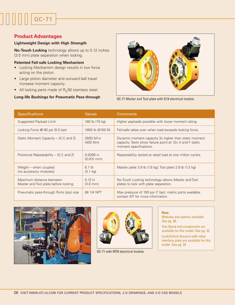
Long-life Bushings for Pneumatic Pass-through QC-71 Master and Tool plate with G19 electrical module
QC-71 with MT8 electrical module
QC-71
Specifications Values Comments
Suggested Payload Limit 180 lb (79 kg) Higher payloads possible with lower moment rating.
Locking Force @ 80 psi (5.5 bar) 1800 lb (8100 N) Fail-safe takes over when load exceeds locking force.
Static Moment Capacity – (X,Y, and Z) 3500 lbf-in Dynamic moment capacity 3x higher than static moment (400 Nm) capacity. Tests show failure point at 12x X and Y static
moment specifications.
Positional Repeatability – (X,Y, and Z) 0.0006 in Repeatability tested at rated load at one million cycles.(0.015 mm)
Weight – when coupled 6.7 lb Master plate 3.9 lb (1.8 kg); Tool plate 2.8 lb (1.3 kg)(no accessory modules) (3.1 kg)
Maximum distance between 0.12 in No-Touch Locking technology allows Master and Tool Master and Tool plate before locking (3.0 mm) plates to lock with plate separation.
Pneumatic pass-through Ports (qty) size (8) 1/4 NPT Max pressure of 100 psi (7 bar), metric ports available, contact ATI for more information.
Note:Modules and options available. See pg. 38.
Tool Stand and components areavailable for this model. See pg. 32.
Lock/Unlock Sensors with robotinterface plate are available for thismodel. See pg. 34.

VISIT WWW.ATI-IA.COM FOR CURRENT PRODUCT SPECIFICATIONS, 2-D DRAWINGS, AND 3-D CAD MODELS 27
“ATI has the widest range of units from the verysmall to the very large payloads, which perfectlysuits our robotic industry.”
Matthew CyglerRobotic AutomationPTY LTD
HOW TO ORDER
9120-071 - - QC-71
Flat ‘B’ (000 = no option)
Flat ‘A’ (000 = no option)
M: Master T: Tool
Example:
9120-071M-000-000
(QC-71 Master plate, no options)
9120-071T-G19-000
(QC-71 Tool plate w/ G19 electrical module)
9120-071T-FN2-000
(QC-71 Tool plate w/ FN2 module
60(Typ.)
B.C. 80
10°(Typ.)
20°(Typ.)
15.1
16.7
B.C. 86
15°
10°
10°
a cover plate is 2.5mm, with a cover plate is 5.6mm.3. Orientation marks are provided to assist in robot teaching.4. Shown with optional G19 Electrical Modules. For other modules
(B) Tool: 9120-071T-G19-000
see the Modules and Options section of the catalog.
Notes:1. Master mounting hardware provided.2. Cover plate is not necessary if robot interface plate provides sealing. The recommended interface plate bore depth without Warning:
Do not apply lock/unlock air pressure without master cover plate properly attached. If cover plate is not used, master should be properly attached to interface. Failure to do so could result in damage to cover plate and o-ring.
(6) Tapped M8 x 1.25, 8 Dp.Equally SpacedCustomer Interface
1
2
345
6
7
8
Flat BFlat A
Tool Side(projection only)
PneumaticPort I.D.
8 H7, 8 Dp.Customer Interface
50 H7, 6 Dp.Customer Interface
30°(Typ.) 56.9
G19-T
150
60.2G19
Modules
Amphenol ConnectorPT02E-14-19S
Thru PortsPneumatic
(8) 1/4 NPT
Thru Ports
(A)
(B)Pneumatic(8) 1/4 NPT
Amphenol ConnectorPT02E-14-19P
Provided
PlateTool32
PlateMaster30.2
CouplingMale
3
20
Boss
Cover Plate
G19-T45.9
49
3.2
G19-M
13.9
62.2Coupled
12.8 M6 SHCS
19
Flat A
Master Side(projection only)
Port
Customer InterfaceEqually SpacedSHCS Provided
PortLock1/8 NPT
(6) Thru Hole for M6 x 40
1/8 NPTUnlock
Flat B
CoverPlate
150
99.1
Customer Interface H7, 6 Dp.6
Customer Interface h7, Boss100
(2)
57G19-M
www.ati-ia.comATI INDUSTRIAL AUTOMATION QC-71
Drawing # 9230-1969-02
(B) Tool: 9120-071T-G19-000(A) Master: 9120-071M-G19-000Part Numbers Shown:

28 VISIT WWW.ATI-IA.COM FOR CURRENT PRODUCT SPECIFICATIONS, 2-D DRAWINGS, AND 3-D CAD MODELS
Product Advantages
The QC-110 was introduced in the Fall of 2004. Itspredecessors, the QC-100 and QC-100i, are stillavailable. Specifications for those models can be foundat www.ati-ia.com.
Excellent Strength-to-Weight Ratio
No-Touch Locking technology allows up to 0.12 inches(3.0 mm) plate separation when locking.
Patented Fail-safe Locking Mechanism
• Locking Mechanism design results in low forceacting on the piston.
• Large piston diameter and outward ball travelincrease moment capacity.
• All locking parts made of Rc58 stainless steel.
Supports DeviceNet Electrical Modules
QC-110 Master and Tool plate with T19 electrical module
QC-110
Specifications Values Comments
Suggested Payload Limit 330 lb (150 kg) Higher payloads possible with lower moment rating.
Locking Force @ 80 psi (5.5 bar) 2700 lb (12,000 N) Fail-safe takes over when load exceeds locking force.
Static Moment Capacity – (X,Y, and Z) 6900 lbf-in Dynamic moment capacity 3x higher than static moment (780 Nm) capacity.
Positional Repeatability – (X,Y, and Z) 0.0006 in Repeatability tested at rated load at one million cycles.(0.015 mm)
Weight – when coupled 13.0 lb Master plate 8.5 lb (3.9 kg); Tool plate 4.5 lb (2.0 kg)(no accessory modules) (5.9 kg)
Maximum distance between 0.12 in No-Touch Locking technology allows Master and Tool Master and Tool plate before locking (3.0 mm) plates to lock with plate separation.
Pneumatic pass-through Ports (qty) size (8) 3/8 NPT Max pressure of 100 psi (7 bar), metric ports available, contact ATI for more information.
Note:Modules and options available. See pg. 38.
Tool Stand and components areavailable for this model. See pg. 32.
Internal Lock/Unlock Sensing
• Reduced stack height.
• No SIP required.
Bolts Directly to 125 mm Bolt Circle
Interface Plates available for other Bolt Circles.
Internal Lock/Unlock sensing - Optional Lock/Unlock sensingbuilt into the body of the Tool Changer
Standardized mounting pattern - Bolts directly to most 125 mmISO robot flanges.

VISIT WWW.ATI-IA.COM FOR CURRENT PRODUCT SPECIFICATIONS, 2-D DRAWINGS, AND 3-D CAD MODELS 29
HOW TO ORDER
9120-110 - - QC-110
Thread version
E: G thread version (Euro) Blank: NPT
Standard Proximity Switch designation (Master only)
D: PNP Quick-disconnect with 5m cablesE: NPN Quick-disconnect no cablesF: NPN Quick-disconnect with 5m cablesG: PNP Quick-disconnect no cablesBlank: No Sensors
Optional Modules - Flat ‘A’ and Flat ‘B’
DeviceNet, Wired Signal or Control Modules must mount to Flat”A” and have an “R” designation on the Master(000 = no option)
M: Master T: Tool
P: Prepared for DeviceNet/Control ModuleNo space: DeviceNet/Control Module is not needed
A: No Boss Master Only (Default for Master) B: 50mm Boss/Recess C: 56mm Boss/Recess D: 60mm Boss/Recess E: 63mm Boss/Recess F: 80mm Boss/Recess (Default for Tool)
Note: Ready-to-Lock Sensors are standard with DeviceNet/Control module only. RTL can be ordered as a separate line item for all other applications.
18.9
17.8
27.8
46.7
Flat B
Customer Interface
(projection only)Master Side
Flat A
(6) Thru Holes For M10 x 50 SHCSProvided Equally Spaced
See Note 2
10
30°
125B.C.
& ToolCustomer Interface Master188Equally Spaced
(Slip Fit), 12 Dp.(2)
74.4T19R-M
UnlockSensor
Thru PortsPneumatic
(8) 3/8 NPT
Thru Ports
(B) (A)
Pneumatic
Lock Port1/8 NPT
Unlock Port1/8 NPT
(8) 3/8 NPT
LockSensor
55.5
Coupled93.1
PlateTool
T19-T45.6
Pin30.1
37.6
PlateMaster
10.1 M10 SHCSProvided
(6) Tapped M10x1.5, 20 Dp.
Customer Interface
(projection only)Tool Side
Flat A
8
7
65
4
3
2
1
Flat B
(B) Tool: 9120-110FT-T19-000(A) Master: 9120-110AM-T19R-000-SGPart Numbers Shown:
Equally Spaced
PneumaticPort I.D.
30°
T19
125
30°
B.C.
Customer InterfaceEqually Spaced
H7, 6 Dp.10 H7, 4 Dp.80
See Note 3Customer Interface
Typ.76.2
T19-T75
Modules
15°
30°
(2)
60.2
20° Typ.
www.ati-ia.comATI INDUSTRIAL AUTOMATION QC-110
-S -
Drawing # 9230-2043-03

30 VISIT WWW.ATI-IA.COM FOR CURRENT PRODUCT SPECIFICATIONS, 2-D DRAWINGS, AND 3-D CAD MODELS
Product Advantages
Extremely Strong Locking Mechanism
No-Touch Locking technology allows up to 0.12 inches(3.0 mm) plate separation when locking.
Patented Fail-safe Locking Mechanism
• Locking Mechanism design results in low forceacting on the piston.
• Large piston diameter and outward ball travelincrease moment capacity.
• All locking parts made of Rc58 stainless steel.
Long-life Bushings for Pneumatic Pass-throughQC-150 Master and Tool plate with G19 electricalmodule and FN2 self-sealing fluid module.
QC-150 with T19 electrical module
QC-150
Specifications Values Comments
Suggested Payload Limit 440 lb (200 kg) Higher payloads possible with lower moment rating.
Locking Force @ 80 psi (5.5 bar) 3600 lb (16,000 N) Fail-safe takes over when load exceeds locking force.
Static Moment Capacity – (X and Y) 12,000 lbf-in(1400 Nm)
Static Moment Capacity – (Z) 10,000 lbf-in(1100 Nm)
Positional Repeatability – (X,Y, and Z) 0.0006 in Repeatability tested at rated load at one million cycles.(0.015 mm)
Weight – when coupled 16.5 lb Master plate 10.5 lb (4.8 kg); Tool plate 6.0 lb (2.7 kg)(no accessory modules) (7.5 kg)
Maximum distance between 0.12 in No-Touch Locking technology allows Master and Tool Master and Tool plate before locking (3.0 mm) plates to lock with plate separation.
Pneumatic pass-through Ports (qty) size (10) 3/8 NPT Max pressure of 100 psi (7 bar), metric ports available, contact ATI for more information.
Dynamic moment capacity 3x higher than static momentcapacity. Tests show failure point at 12x X and Y staticmoment specifications.
Note:Modules and options available. See pg. 38.
Tool Stand and components areavailable for this model. See pg. 32.
Lock/Unlock Sensors with robotinterface plate are available for thismodel. See pg. 34.

VISIT WWW.ATI-IA.COM FOR CURRENT PRODUCT SPECIFICATIONS, 2-D DRAWINGS, AND 3-D CAD MODELS 31
"ATI has been FANUC Robotics North America, Inc.preferred Tool Changer since 1996."
Peter H. StephanProgram Manager for Stamping
HOW TO ORDER
9120-150 - - QC-150
Flat ‘B’ (000 = no option)
Flat ‘A’ (000 = no option)
M: Master T: Tool
Example:
9120-150M-000-000
(QC-150 Master plate, no options)
9120-150T-G19-FN2
(QC-150 Tool plate w/ G19 electrical module andFN2 fluid module)
9120-150M-R19-000
(QC-150 Master plate w/ R19 electrical module
10°
20°
20°
30°
20°
B.C. 125
B.C. 125
15°
10°
23.132.1
1
2
3
4
56
7
8
Flat A
9
Flat B
10
(6) Tapped M10 x 1.5, 20 Dp.Equally SpacedCustomer Interface
Tool Side(projection only)
57
FN
G19
(Typ.)84
60
200
Equally spaced
10 H7, 20 Dp.Customer Interface
80 H7, 8 Dp.Customer Interface
Modules
Modules
(2)
60.2G19
Modules
FN2- Fluid/Air Modules
Part Numbers:
G19- Electrical Modules4. Optional modules shown listed below. Consult catalog for other options.3. Orientation marks are provided to assist in robot teaching.
(A) Master: 9120-150M-G19-FN2(B) Tool: 9120-150T-G19-FN2
Notes:1. Master mounting hardware provided.2. Cover plate is not necessary if robot interface plate provides sealing. The recommended interface plate bore depth without a cover plate is 2.5mm, with a cover plate is 5.6mm.
Warning: Do not apply lock/unlock air pressure without master cover plate properly attached. If cover plate is not used, master should be properly attached to interface. Failure to do so could result in damage to cover plate and o-ring.
(projection only)
SHCS Provided
D1
Customer Interface
Flat A
Flat B
Equally Spaced
(6) Thru Hole for M10 X 60
1/8 NPTUnlockPort
Master Side
D2
Cover139
Customer Interface10 H7, 30 Dp. (D2)(1)
H7, 10 Dp. (D1)
200
160 h7, BossCustomer InterfacePlate
(1) 10
40.9FN
Modules
PT02E-14-19P
Thru Ports
PT02E-14-19S
(B)
(10) 3/8 NPTPneumatic
PneumaticThru Ports
1/8 NPTLock Port
Amphenol Connector
(10) 3/8 NPT
Amphenol Connector
(A)
Cover Plate3.2
87.2Coupled
45.9G19-T
49G19-M
26.4Male Plate
Coupling
Master47.1
3 Boss
20.6 M10 SHCSProvided
40.1ToolPlate
www.ati-ia.comATI INDUSTRIAL AUTOMATION QC-150
Drawing # 9230-1971-04

32 VISIT WWW.ATI-IA.COM FOR CURRENT PRODUCT SPECIFICATIONS, 2-D DRAWINGS, AND 3-D CAD MODELS
TOOL STANDS FOR QC-40 TO QC-150
TSM Modular Tool Stand System
The ATI TSM (Tool Stand Medium) Modular Tool StandSystem is compatible with the medium range of ToolChangers—QC-40 through QC-150. The Stand isdesigned for maximum flexibility to fit most customerapplications. The modular system allows you to buildyour own tool storage rack based on the number oftools, positioning, orientation, and mountingarrangements required. The TSM provides a uniqueoption to utilize a complete arrangement of modules, oruse only the tooling-interface Pins and V-blocks andmount them on your own fixture.
Product Advantages
Modular System allows for customization.
V-blocks – 4140 Hardened Tool Steel Pin Blocks providerepeatable tool drop-off.
Use Extruded Rails and Base, or mount the racks onyour own platform.
Proximity Sensor Option
Adapts to TSL or TSS Modules as well.
Product Features
V-Blocks and PinsThe TSM utilizes V-shaped 4140 Hardened Steel Blocks that receivecorresponding steel alignment pins. The V-blocks are designed to mountto extruded railing components or bolt directly onto custom fixtures. Themating alignment pins are included with the TSM Tooling Plate assemblieswhich attach to the tool. The Alignment Pins are also sold separately asreplacement parts or for custom applications.
Mounting ModulesThe TSM Mounting Modules are specifically designed to interface withthe Tooling Plate assemblies for each corresponding Tool Changer.Mounting Modules mount onto the included TSM Rail components, oryou may use the existing bolt patterns to mount to your custom fixture.Mounting Modules come in 2 configurations: Horizontal or Verticalorientation. See the TSM Product Index for tool interfacing option details.
Tooling Plate AssembliesThe TSM Tooling Plate Assemblies attach to your tooling. Alignment Pinsare included with the Tooling Plates. Customers can either specify theirtool attachment requirements at the time of purchase or choose BlankTooling Plates and opt to machine their tooling Bolt Patterns in later.
Post and Rail ModulesChoose from several TSM Post and Rail Modules to build your specificStand configuration. The Post Modules, Horizontal Modules, andHorizontal Extensions are aluminum-extruded rails (Bosch-series).Alignment and mounting hardware is included. Basic standard raillengths are offered, but customers may specify other lengths.
Adapter ModulesTSM Adapter Modules are specifically designed adapter plates withmounting hardware included that attach Mounting Modules to Rail orPost Modules. Adapter Modules extend the flexibility of the Tool StandSystem to cover a myriad of configuration options.
Spring Plate ModuleThe TSM Spring Plate Module is an option to help stabilize long end-effector tooling while in the stand by applying a spring-generatedpreload on the Tooling Plate. The preload reduces slack in the fitbetween the alignment pins and the stand, resulting in less tilt and amore repeatable drop-off and pick-up location. The TSM Spring PlateModule attaches directly to the TSM Vertical Mounting Module.
Mountingmodule
Adapter module
Horizontalextension
Tool-side Tool ChangerTool interface plate
Post module
Horizontal module

VISIT WWW.ATI-IA.COM FOR CURRENT PRODUCT SPECIFICATIONS, 2-D DRAWINGS, AND 3-D CAD MODELS 33
Notes: 1. Tooling Plate listed has blank customer interface. Custom bolt 8. Adapts Mounting Module to Large Tool Stand Post Weldment.pattern is available upon request and will require new part number. 9. Dowel Plate recommended for Rail-to-Rail Positional Repeatability.
2. May specify shorter rail lengths. Cut charge applies. 10. Attaches to Vertical Mounting Module 9120-TSM-MM-4068. 3. Adapts MM-3597 or MM-4018 to vertical rail, and rail ends 11. V-Block Plate 3700-20-4096 included (2).4. Barrel Prox. 8590-9909999-45 (M18x1.0 thread) Sold Separately. 12. V-Block Plate 3700-20-4097 included (2).5. Uses Pin 3700-20-3590, or 3700-20-4017. 13. Uses Back Plate 3700-20-4096 Sold Separately.6. Uses Pin 3700-20-3594, or 3700-20-4016. 14. Uses Back Plate 3700-20-4097 Sold Separately.7. Receiving Block mounts to rail; bolted or welded to any structure.
Quick-Change TSM Tool Stand Interfacing
Option #1: Horizontal QC OrientationQC Model QC-40 QC-41 QC-60 QC-71 QC-110 QC-150
Mounting Module 9120-TSM-MM-3597 9120-TSM-MM-3597 9120-TSM-MM-3597 9120-TSM-MM-3597 9120-TSM-MM-4018 9120-TSM-MM-4018Tooling Plate 9120-TSM-TP-4055 9120-TSM-TP-4056 9120-TSM-TP-4057 9120-TSM-TP-4058 9120-TSM-TP-4059 9120-TSM-TP-4060Sensor Module 9120-TSM-SM-4206 9120-TSM-SM-4206 9120-TSM-SM-4206 9120-TSM-SM-4206 9120-TSM-SM-4205 9120-TSM-SM-4205Notes See Note 1,11 See Note 1,11 See Note 1,11 See Note 1,11 See Note 1,12 See Note 1,12Customer Drawing 9230-20-1892 9230-20-1893 9230-20-1894 9230-20-1895 9230-20-1896 9230-20-1897
Option #2: Vertical QC OrientationQC Model QC-40, -41, -60, -71
Mounting Module 9120-TSM-MM-4068Tooling Plate 9120-TSM-TP-4069Sensor Module 9120-TSM-SM-4206Notes See Note 1Customer Drawing 9230-20-1919
Configurable Tool Stand Module System – Overview Drawing # 9230-20-1880
Module Name Post Module 48" Post Module 72" Horiz. Module 36" Horiz. Module 18" Horiz. Ext. 6" Horiz. Ext. 10"Part Number 9120-TSM-PM-3318 9120-TSM-PM-3322 9120-TSM-HM-3317 9120-TSM-HM-3323 9120-TSM-HE-3320 9120-TSM-HE-3321Notes See Note 2 See Note 2 See Note 2 See Note 2 See Note 2 See Note 2Customer Drawing 9230-20-1898 9230-20-1899 9230-20-1900 9230-20-1901 9230-20-1902 9230-20-1903
Module Name Adapter Module Spring Plate Receiver Block Receiver Block Dowel Plate Dowel PlatePart Number 9120-TSM-AM-4019 9120-TSM-SP-5093 9120-TSM-RB-3591 9120-TSM-RB-3595 9120-TSM-DP-4203 9120-TSM-DP-4204Notes See Note 3 See Note 10 See Note 5,7,13 See Note 6,7,14 See Note 9 See Note 9Customer Drawing 9230-20-1904 9230-20-2514 9230-20-1906 9230-20-1907 9230-20-2039 9230-20-2039
Module/Part Name Debris Shield Actuator Debris Shield Shield Arm Sensor Module Tooling Pins - 9230-20-2041Part Number 9120-TSM-DSA-4249 9120-TSM-DS-4250 3700-20-3376 9120-TSM-SM-4205 3700-20-3590 (M12 Thread)
Shield System Requires: Actuator, Shield and Arm 3700-20-3594 (M10 Thread)Notes See Note 4 See Note 4 3700-20-4016 (M10 Thread)Customer Drawing 9230-20-2102 9230-20-2102 9230-20-2102 9230-20-1905 3700-20-4017 (M12 thread)
Option #2: Vertical QC OrientationQC Model QC-110, -150Mounting Module 9120-TSM-MM-4070Tooling Plate 9120-TSM-TP-4071Sensor Module 9120-TSM-SM-4205Notes See Note 1Customer Drawing 9230-20-1920
Complete assembled custom configurations are available, contact ATI for more information.

34 VISIT WWW.ATI-IA.COM FOR CURRENT PRODUCT SPECIFICATIONS, 2-D DRAWINGS, AND 3-D CAD MODELS
Figure 1: Side view of Master plate withSensor Interface Plate (SIP) system.
The Sensor Interface Plate (SIP) system has beendesigned to provide Lock and Unlock sensing inside theRobot Interface Plate. The SIP consists of Lock andUnlock sensors, detection shaft, sensing plate, andinterface plate. The SIP system is compatible with all ofthe Standard Series Tool Changer models except theQC-5 and QC-110. Figures 1 through 4 show how theSIP works.
Sensor InterfacePlate (also acts as
Robot InterfacePlate)
Master plate
Figure 2: Section view of Figure 1 showingposition of SIP system when locked withoutTool plate. Neither the Lock nor Unlocksensors are activated. In this position, this isdescribed as a missed Tool condition.
Figure 4: Close-up of SIP in Unlockposition. Unlock sensor activated bythe detection shaft. Lock sensor isnot activated.
Figure 3: Close-up of SIP in Lockposition with the Tool plate. Locksensor activated by the detection shaft.
Sensor plate Piston
Detection shaft
Unlock sensor Lock sensor
SENSOR INTERFACE PLATE SYSTEM

The SIP is factory-installed when ordered with the Master plate. The SIP may also be ordered separately.
VISIT WWW.ATI-IA.COM FOR CURRENT PRODUCT SPECIFICATIONS, 2-D DRAWINGS, AND 3-D CAD MODELS 35
HOW TO ORDER
9120- -M-SIP-
Number representing the interface plate modeled to fit mountingflange (contact ATI for a list of these interface plates).
Type of proximity switch:A: NPN hardwired 5m cablesB: PNP hardwired 5m cablesC: 125 VAC switchD: PNP Quick-disconnect switch with 5m cablesE: NPN Quick-disconnect switch with no cablesF: NPN Quick-disconnect switch with 5m cablesG: PNP Quick-disconnect switch with no cablesH: PNP with cable combining both lock and unlock into one cableK: 12-24 DC 2-wire switch with 2m cablesL: Hall effect sensor M: PNP Quick-disconnect switch with 90 degree cables N: 2-wire sensor (lock only) P: PNP hard-wired sensor with 2m cable w/ male M8 connector Q: 4mm PNP sensor 10 in. cable with Nano connector for QC-11,
-20 and -21QN: 4mm NPN sensor 10 in. cable with Nano connector for QC-11,
-20 and -21
Indicates Sensor Interface Plate
M: Master
QC Model

36 VISIT WWW.ATI-IA.COM FOR CURRENT PRODUCT SPECIFICATIONS, 2-D DRAWINGS, AND 3-D CAD MODELS
Product Advantages
Built-in Electrical Module has five pins that may beused for tool-ID. The Master connector contains thesignals for the detection sensor.
No-Touch Locking technology allows up to 0.1 inches(2.5 mm) plate separation when locking.
Detection Sensor detects when the Tool plate is within0.6 inches (1.5 mm) of the Master plate, signalingReady-to-Lock.
Self-sealing Pneumatic Ports on the Master-side sealwhen the Master and Tool separate. QC-300 Master and Tool plate with T19 electrical module
QC-300 with G19, FN2 and V34electrical modules.
QC-300
Specifications Values Comments
Suggested Payload Limit 1000 lb (450 kg) Higher payloads possible with lower moment rating.
Locking Force @ 80 psi (5.5 bar) 7900 lb (35,000 N) Fail-safe takes over when load exceeds locking force.
Static Moment Capacity –(X and Y) 29,000 lbf-in(3300 Nm)
Static Moment Capacity – (Z) 25,000 lbf-in(2800 Nm)
Positional Repeatability – (X,Y, and Z) 0.0006 in Repeatability tested at rated load at one million cycles.(0.015 mm)
Weight – when coupled 42 lb Master plate 26 lb (11.8 kg); Tool plate 16 lb (7.3 kg)(no accessory modules) (19.0 kg)
Maximum distance between 0.10 in No-Touch Locking technology allows Master and Tool Master and Tool plate before locking (2.5 mm) plates to lock with plate separation.
Pneumatic pass-through Ports (qty) size (10) 3/8 BSPP (G) Max pressure of 100 psi (7 bar), (8) self-sealing ports, metric ports available, contact ATI for more information.
Dynamic moment capacity 3x higher than static momentcapacity. Tests show failure point at 12x X and Y staticmoment specifications.
Note:Modules and options available. See pg. 38.
Tool Stand and components areavailable for this model. See pg. 51.
Lock/Unlock Sensors with robotinterface plate are available for thismodel. See pg. 34.

VISIT WWW.ATI-IA.COM FOR CURRENT PRODUCT SPECIFICATIONS, 2-D DRAWINGS, AND 3-D CAD MODELS 37
“I have found the ATI QC Tool Changer to be very reliableand robust for robot end-of-arm tooling applications.”
Vipin PatelFANUC Robotics
HOW TO ORDER
9120-300 - - QC-300
Flat ‘B2’ (000 = no option)
Flat ‘B1’ (000 = no option)
Flat ‘A2’ (000 = no option)
Flat ‘A1’ (000 = no option)
M: Master T: Tool
- -
B.C. 200
30°
10°(Typ.)
18.5°
18.5°
20°
20°
12
29
23.1
25.1
113.5(Typ.)
B.C. 166
20°30°
MS3102A14S-5S
B2
10
8
7
65 4
3
2
1
Customer Interface9
Flat A
Flat B
Equally Spaced(6) Tapped M12 x 1.75, 20 Dp.
(Built-in Electrical Module)
(projection only)Tool Side
A2
A1
B1
Amphenol Connector
PneumaticPort I.D.
H8, 8 Dp.125Customer Interface
(Typ.)40°
12Customer Interface
H7, 20 Dp.
T19-T31.6 75
30.2
259
3. Orientation marks are provided to assist in robot teaching.4. Shown with optional T19 Electrical Modules. For other modules see the Modules and Options section of the catalog.
(B) 9120-300T-000-000-T19-000(A) 9120-300M-000-000-T19-000Part Numbers Shown:
Notes:1. Master mounting hardware provided.2. Cover plate is not necessary if robot interface plate provides sealing. The recommended interface plate bore depth without a cover plate is 5.5mm, with a cover plate is 8.6mm.
Warning: Do not apply lock/unlock air pressure without master cover plate properly attached. If cover plate is not used, master should be properly attached to interface. Failure to do so could result in damage to cover plate and o-ring.
G 1/4 Lock Port
G 1/4 Unlock Port
Amphenol ConnectorMS3102E22-14P
Thru PortsMating Surface)
(25.1 FromThru PortsPneumatic
PortsSelf-SealingPneumatic(8) G 3/8
(9 & 10)
(10) G 3/8
(2) G 3/8 Pneumatic
Amphenol ConnectorMS3102E22-14S
Coupled110
PlateTool
T19-T45.7
T19-M54.2
55 CouplingMale45
PlateMaster
Boss63.2
55
Cover Plate21.7 M12 SHCS
Provided
A1
B2
Customer Interface
Flat AFlat B
Equally SpacedSHCS Provided
(Built-in Electrical Module)
(projection only)Master Side
B1
(6) Thru Hole for M12 x 70
Amphenol ConnectorMS3102A18-1P
A2
Customer Interface185 h7, Boss44.6
34.9
74.2T19-M
60.2
ModulesT19
H7, 20 Dp.Customer Interface
259
12(2)
184CoverPlate
www.ati-ia.comATI INDUSTRIAL AUTOMATION QC-300
Drawing # 9230-1973-03

38 VISIT WWW.ATI-IA.COM FOR CURRENT PRODUCT SPECIFICATIONS, 2-D DRAWINGS, AND 3-D CAD MODELS
STANDARD SERIES MODULES AND OPTIONS
Electrical and Signal Modules
Part # # Pins Voltage Connector Type
B15-M/T 15 3A/50VAC high-density D-sub connector
E10-005-M/T 10 3A/50VAC solder conn., miniature size
E2A-M/T 20 3A/50VAC solder conn., miniature size
E3A-M/T 30 3A/50VAC solder conn., miniature size
RF19 Master- and Tool-side electrical modules with M16 screw-onconnectors.
For Tool Changer Models: QC-5
Part # # Pins Voltage Connector Type
A15-M/T 15 3A/50VAC high-density D-sub connector
E10-010-M/T 10 3A/50VAC solder conn., miniature size
E20-010-M/T 20 3A/50VAC solder conn., miniature size
For Tool Changer Models: QC-11
Part # # Pins Voltage Connector Type Notes
GF19-M/T 19 3A/125VAC M16 screw-on connector Swivel connector provides 5 unique positions across 180 degrees, Cables available.
RF19-M/T 19 3A/125VAC M16 screw-on connector 19 pins available for customer use, Right-angled connector, Cables available.
RF14-T 14 3A/125VAC M16 screw-on connector 19 pins (14 available for customer use), RF19 module with (0–9) tool-ID, mates with RF19-M or any G, R, S or T series modules with 19 pins, Cables available
SF19-M/T 19 3A/125VAC M16 screw-on connector 19 pins available for customer use, Inline connector, Cables available.
For Tool Changer Models: QC-40, 41, 71, 110, 150, and 300 - M16 Screw-On Connectors
Part # # Pins Voltage Connector Type Notes
K12-M/T 12 3A/50VAC 12 mm industrial connector 12 pins available for customer use
KM14-M/T 14 5A/250VAC mini. MS quick-disconnect 14 pins available for customer use, 12 pins at 5 amps and 2 pins at 13 amps
D15-M/T 15 3A/50VAC high-density D-sub connector 15 pins available for customer use
K19-M/T 19 3A/50VAC mini. MS quick-disconnect 19 pins available for customer use
K14-T 14 3A/50VAC mini. MS quick-disconnect 19 pins (14 available for customer use), 16 tool-IDs, mates with K19-M
KF19-M/T 19 3A/50VAC M16 screw-on connector 19 pins available for customer use, Cables available.
KG19-M/T 19 3A/50VAC mini. MS quick-disconnect Swivel connector provides 5 unique positions across 180 degrees
K26-M/T 26 3A/50VAC mini. MS quick-disconnect 26 pins available for customer use
For Tool Changer Models: QC-20, 21 and 60
A variety of Electrical Modules are available that enableone to pass discrete signals through the Tool Changer.Some modules are also available supporting ToolChanger I/O, such as Lock, Unlock, and Ready-to-Lockproximity sensors, as well as tool-ID. Military-style orM16 connectors are standard on most electricalmodules. Custom versions are available upon request.All of our Standard Series Electrical and Signal Modulesare compatible with our Heavy Automation ToolChangers with an adapter block. Contact ATI for moreinformation. Visit www.ati-ia.com for a complete list ofavailable modules.
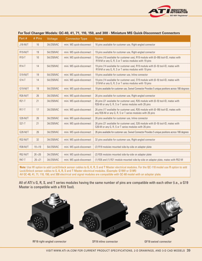
VISIT WWW.ATI-IA.COM FOR CURRENT PRODUCT SPECIFICATIONS, 2-D DRAWINGS, AND 3-D CAD MODELS 39
Note: Use W option to add Lock/Unlock sensor cables to G, K, R, S and T Master electrical modules. For the QC-110 model use R option to addLock/Unlock sensor cables to G, K, R, S and T Master electrical modules. (Example: G19W or S19R)All QC-40, 41, 71, 110, 150, and 300 electrical and signal modules are compatible with QC-60 model with an adapter plate.
All of ATI's G, R, S, and T series modules having the same number of pins are compatible with each other (i.e., a G19Master is compatible with a R19 Tool).
RF19 right-angled connector SF19 inline connector GF19 swivel connector
R52-M/T 26 +26 3A/250VAC mini. MS quick-disconnect (2) R26 modules mounted side-by-side on adapter plate
R47-T 26 +21 3A/250VAC mini. MS quick-disconnect (1) R26 and (1) R21 module mounted side-by-side on adapter plate, mates with R52-M
R26-M/T 26 3A/250VAC mini. MS quick-disconnect 26 pins available for customer use, Right-angled connector
R21-T 21 3A/250VAC mini. MS quick-disconnect 26 pins (21 available for customer use), R26 module with (0–9) tool-ID, mates with R26-M or any G, R, S or T series modules with 26 pins
R17-T 17 3A/250VAC mini. MS quick-disconnect 26 pins (17 available for customer use), R26 module with (0–99) tool-ID, mates with any R26-M or any G, R, S or T series modules with 26 pins
S26-M/T 26 3A/250VAC mini. MS quick-disconnect 26 pins available for customer use, Inline connector
S21-T 21 3A/250VAC mini. MS quick-disconnect 26 pins (21 available for customer use), S26 module with (0–9) tool-ID, mates withS26-M or any G, R, S or T series modules with 26 pins
G26-M/T 26 3A/250VAC mini. MS quick-disconnect 26 pins available for customer use, Swivel Connector Provides 5 unique positions across 180 degrees
R32-M/T 32 3A/250VAC mini. MS quick-disconnect 32 pins available for customer use, Right-angled connector
R38-M/T 19 +19 5A/250VAC mini. MS quick-disconnect (2) R19 modules mounted side-by-side on adapter plate
For Tool Changer Models: QC-40, 41, 71, 110, 150, and 300 - Miniature MS Quick-Disconnect Connectors
Part # # Pins Voltage Connector Type Notes
J16-M/T 16 3A/250VAC mini. MS quick-disconnect 16 pins available for customer use, Right-angled connector
R19-M/T 19 5A/250VAC mini. MS quick-disconnect 19 pins available for customer use, Right-angled connector
R10-T 10 5A/250VAC mini. MS quick-disconnect 19 pins (10 available for customer use), R19 module with (0–99) tool-ID, mates with R19-M or any G, R, S or T series modules with 19 pins
R14-T 14 5A/250VAC mini. MS quick-disconnect 19 pins (14 available for customer use), R19 module with (0–9) tool-ID, mates with R19-M or any G, R, S or T series modules with 19 pins
S19-M/T 19 5A/250VAC mini. MS quick-disconnect 19 pins available for customer use, Inline connector
S14-T 14 5A/250VAC mini. MS quick-disconnect 19 pins (14 available for customer use), S19 module with (0–9) tool-ID, mates with S19-M or any G, R, S or T series modules with 19 pins
G19-M/T 19 5A/250VAC mini. MS quick-disconnect 19 pins available for customer use, Swivel Connector Provides 5 unique positions across 180 degrees

40 VISIT WWW.ATI-IA.COM FOR CURRENT PRODUCT SPECIFICATIONS, 2-D DRAWINGS, AND 3-D CAD MODELS
STANDARD SERIES MODULES AND OPTIONS
Special Application Modules
X7B coax cable module
We have a variety of modules that can pass utilitiessuch as ultrasonic welding, video, camera signals, andmore. Contact ATI to select the right module for yourapplication. We welcome the opportunity to design amodule for your application. Visit www.ati-ia.com for acomplete list of available modules.
Part # Description
X7B-M/T Coax cable module, single 75 Ohm contact, BNC connector, compatible QC models: 40, 41, 71, 110, 150, 300
X7C-M/T High voltage module for ultrasonic welding applications, SHV connector, 3A/2000VAC, 30kHz, compatible QC models: 40, 41, 71, 110, 150, 300
X7D-M/T Coax power module with BNC connectors (for use with Branson ultrasonic equipment) 5A/500VAC, compatible QC models: 40, 41, 71, 110, 150, 300
BP-M/T PROFIBUS pass-through module, 10 pins, 5A/24VAC, compatible with QC-110
RX12-M/T Camera module for Sony XC series camera, Hirose 12-pin connector, compatible QC models: 40, 41, 71, 110, 150, 300
Electrical and Signal Modules (cont.)
Part # # Pins Voltage Connector Type Notes
MT8-M/T 8 20A/500VAC/700VDC MS threaded connector High-power module
MT8L-M/T 8 20A/500VAC/700VDC MS threaded connector Connector relocated 180 degrees from standard MT8
MT9-M/T 9 28A/500VAC/700VDC MS threaded connector Compatible only with QC-100 or larger to handle maximum rated current
MT14-M/T 14 13A/500VAC/700VDC MS threaded connector MT14A-M (Master-side) MT14-T (Tool-side)
MTR14-M/T 14 13A/500VAC/700VDC MS threaded connector Modified MT14 with connector relocated to mount with connector flange parallelto mounting flat
For Tool Changer Models: QC-40, 41, 71, 110, 150, and 300 - High-Power - MS Threaded Connectors
Part # # Pins Voltage Connector Type Notes
T19-M/T 19 5A/250VAC MS threaded connector 19 pins available for customer use, Right-angled connector
T14-T 14 5A/250VAC MS threaded connector 19 pins (14 available for customer use), T19 module with (0–9) tool-ID, mates withT19-M or any G, R, S, or T series modules with 19 pins
T10-T 10 5A/250VAC MS threaded connector 19 pins (10 available for customer use), T19 module with (0–99) tool-ID, mates withT19-M or any G, R, S, or T series modules with 19 pins
For Tool Changer Models: QC-40, 41, 71, 110, 150, and 300 - MS Threaded Connectors
TT1199 eexxppoosseedd ttoo sshhooww ddeessiiggnn.. RR1199,,RR2266,, SS1199 aanndd SS2266 hhaavvee tthhee ssaammeeddeessiiggnn..
Aluminum housing
Rhodium-plated contact pins(Rhodium is a strong wear-resistant metal
with excellent conductivity)
V-ring seal (watertight seal when locked)
Spring pins with rhodium-plated heads recessed to prevent external touching
Aluminum housing
Gold-plated spring housing
T26-M/T 26 3A/250VAC MS threaded connector 26 pins available for customer use

VISIT WWW.ATI-IA.COM FOR CURRENT PRODUCT SPECIFICATIONS, 2-D DRAWINGS, AND 3-D CAD MODELS 41
Pneumatic, Fluid, and Vacuum Modules
P38A pneumatic module
ATI offers a variety of modules to pass pneumatic, vacuum, andfluid utilities. Pneumatic service modules are available with self-sealing or pass-through ports, both having anodized-aluminumbodies. Pass-through pneumatic ports utilize rubber bushings toachieve a durable and reliable seal. They are suitable for bothvacuum and pressure service. High-flow ports for vacuum serviceutilize rubber V-rings for sealing and cannot support positivepressures. Fluid/Pneumatic modules are made from stainless steelmaterials and utilize self-sealing ports with U-cup seals. Thisminimizes fluid/air loss during a tool change and prevents corrosion.Self-sealing ports cannot support vacuum service. Visit www.ati-ia.com for a complete list of available modules.
Part # Port Size # Ports Cv Rating Compatible QC Models Notes
P18-M/T 1/8 NPT 4 0.65 40, 41, 60*, 71, 110, 150, 300 Pass-through ports
P186-M/T 1/8 NPT 6 0.65 40, 41, 60*, 71, 110, 150, 300 Pass-through ports
P186A-M/T 1/8 NPT 6 0.65 40, 41, 60*, 71, 110, 150, 300 Pass-through ports, Ported axially
P186A-E-M/T 1/8 BSPP (G) 6 0.65 40, 41, 60*, 71, 110, 150, 300 Pass-through ports, Ported axially
P05-M/T M5 10 0.25 40, 41, 60*, 71, 110, 150, 300 Pass-through ports
P14-M/T 1/4 NPT 2 1.03 40, 41, 60*, 71, 110, 150, 300 Pass-through ports
P238-M/T 3/8 NPT 2 2.45 40, 41, 60*, 71, 110, 150, 300 Pass-through ports
P38-M/T 3/8 NPT 4 2.45 110, 150, 300 Pass-through ports, Adapter plate required
P38A-M/T 3/8 NPT 4 2.45 41, 60*, 71, 110, 150, 300 Pass-through ports, Ported axially
P38-E-M/T 3/8 BSPP (G) 4 2.45 110, 150 Pass-through ports, Includes adapter plates
Pneumatic Modules
Part # Port Size # Ports Cv Rating Compatible QC Models Notes
FG2-M/T 3/8 BSPP (G) 2 1.4 40, 41, 71, 110, 150, 300 Self-sealing ports, Replaces F02-E
FG2A-T 3/8 BSPP (G) 2 1.4 40, 41, 71, 110, 150, 300 Pass-through ports, mates with FG2-M
Fluid/Pneumatic Modules
Part # Port Size # Ports Cv Rating Compatible QC Models Notes
V34-M/T 1-3/4 BSPP (G) 1 8.0 (est.) 40, 41, 60*, 71, 110, 150, 300 Pass-through port, vacuum only
Vacuum Modules
All pass-through pneumatic ports support air and vacuum. *Requires adapter plate
Can add Viton as an option for FN/FG 2 or 4 - should add V at the end of the module number before -M or -T. No dashes between V and module number.
FN2-M/T 3/8 NPT 2 1.4 40, 41, 71, 110, 150, 300 Self-sealing ports, Replaces F02-N
FN2A-T 3/8 NPT 2 1.4 40, 41, 71, 110, 150, 300 Pass-through ports, mates with FN2-M
FG4-M/T 3/8 BSPP (G) 4 1.4 71, 110, 150, 300 Self-sealing ports, Replaces F04-E
FG4A-T 3/8 BSPP (G) 4 1.4 71, 110, 150, 300 Pass-through ports, mates with FG4-M
FN4-M/T 3/8 NPT 4 1.4 71, 110, 150, 300 Self-sealing ports, Replaces F04-N
FN4A-T 3/8 NPT 4 1.4 71, 110, 150, 300 Pass-through ports, mates with FN4-M
*Requires adapter plate

42 VISIT WWW.ATI-IA.COM FOR CURRENT PRODUCT SPECIFICATIONS, 2-D DRAWINGS, AND 3-D CAD MODELS
TOOL CHANGERS FOR HEAVY AUTOMATION
Robotic Tool Changers for HeavyAutomation
The Heavy Automation Robotic Tool Changer line hasbeen developed for the resistance welding market andmedium- to heavy-duty material handling. Becausethese Tool Changers use modules to pass utilities (e.g.,water, electrical, pneumatic, etc.), they are able tohandle numerous applications by simply selecting theappropriate modules. These Tool Changers haveextremely high moment capacity for use in demandingapplications.
Product Advantages
Modular Design: Power, coolant, servo, and control/signal features are built into separate modules makingmaintenance easy. Module housings use a commonmounting design for use on the QC-210, QC-310, QC-510, and QC-1210, increasing flexibility in configuring theTool Changer.
Extremely High Moment Capacity: Many ToolChangers with high moment loads gap (separatebetween the Master and Tool plates) during high-speedmoves, causing disruption to utilities such as Fieldbusnetworks and servo lines. The Heavy Automation seriesfrom ATI can take on dynamic moment loads andmaintain utility functions during full range of motion.
In-the-Body Sensing: Lock/Unlock/Ready-to-Locksensors have been integrated into the body of the ToolChanger. This design provides the advantages ofreduced stack height and reduced weight withoutsacrificing the strength of the unit. Two Ready-to-Locksensors in the body afford the robot programmer theability to better teach Master-to-Tool coupling.
Integrated Solution for Control/Signal Modules:
Control/Signal modules support an integrated valve thatis internally-ported and interfaces with internal cablerouting in the Tool Changer body.
Easy Dress: The modules are designed to placeelectrical, pneumatic, and water ports in-line, affordingthe customer an easy dress-out.
Integrated Bolt Circle Patterns: Common, industry-standard bolt circle patterns have been integrateddirectly into the Tool Changer body of these models,often eliminating the need for an interface plate, whichreduces stack height.
Battery Backup for Servo: The servo module has abattery backup option on the Tool-side to allow theservo to hold information while disconnected from therobot.
Strong Power and Servo Module Housings: High-strength aluminum and FR4/G10 composite insulatingmaterial are used for the primary current and servomodules to prevent damage from crashes and cablestress.
Weight and Size Reduction: Weight and size are keptas small as possible without reducing reliability orperformance.
No-Touch Contacts Increase Safety: 200-amp powerand signal modules have contacts that are nottouchable on the Master-side—increasing safety andworld-wide acceptance.
High-flow Fluid Module: The Fluid/Pneumatic modulehas a Cv of 3.1 allowing for better weld gun andtransformer cooling.
QC-210 Heavy Automation Tool Changer

VISIT WWW.ATI-IA.COM FOR CURRENT PRODUCT SPECIFICATIONS, 2-D DRAWINGS, AND 3-D CAD MODELS 43
Common Utility Module Mounting
Modules mount from the Tool Changer face to provide extra support for applications with heavy dress packages. Allmodules use a common mounting pattern so they can be swapped between the QC-210, QC-310, and QC-510models and located on any of three available flats (‘B’, ‘C’, or ‘D’). Flat ‘A’ on the Master-side must always have aLock/Unlock Pneumatic and Valve Mounting Adapter. Control/Signal Modules can be located on flat ‘A’ and arepiggybacked on the Lock/Unlock Pneumatic and Valve Mounting Adapter.
QC-210 module-to-body connection
Flat ‘D’
Flat ‘B’
Flat ‘C’ Flat ‘A’
Pneumatic/Valve adapter block

44 VISIT WWW.ATI-IA.COM FOR CURRENT PRODUCT SPECIFICATIONS, 2-D DRAWINGS, AND 3-D CAD MODELS
Product Advantages
No-Touch Locking technology allows up to 0.1 inches (2.5 mm) plate separation when locking.
Ready-to-Lock Sensors (2) detect when the Tool plate iswithin 0.06 inches (1.5 mm) of the Master plate, ensuringthat the Tool plate and Master plate are parallel.
Patented Fail-safe Locking Mechanism
• Locking mechanism design results in low force acting onthe piston.
• Large piston diameter and outward ball travel increasemoment capacity.
• All locking parts are made of Rc58 stainless steel.
Integrated Lock/Unlock Sensing Proximity Sensors toindicate Lock/Unlock position for safe Coupling/Uncoupling.
Mounts Directly to most 200 kg Robots
(no SIP plate required, see stack height below).
QC-210 with pneumatic module and control module
Specifications Values Comments
Suggested Payload Limit 500 lbs Higher payloads possible with lower moment rating.(220 kg)
Locking Force @ 80 psi 7000 lbs Axial holding force.(31,000 N)
Static Moment Capacity (X and Y) 24,000 lbf-in Higher dynamic moment possible depending on module selection.(2700 Nm) Failure test exceeded 120,000 lbf-in (13,560 Nm) moment.
Static Moment Capacity (Z) 20,000 lbf-in (Torsion) Higher dynamic moment possible depending on module(2300 Nm) selection. Failure test exceeded 100,000 lbf-in (11,300 Nm) moment.
Positional Repeatability (X,Y, and Z) 0.0006 in Repeatability tested at rated load at over one million cycles.(0.015 mm)
Weight (when coupled) 17.0 lbs Master: 11.6 lbs (5.3 kg) (no accessory modules) (7.7 kg) Tool: 5.4 lbs (2.4 kg)
Stack height when locked 3.43 in Stack height for 125 mm ISO pattern(103 mm)4.06 in Stack height for 160 mm ISO pattern (includes IP)(120 mm)
Body size (no modules) 6.3 x 6.3 in Size of body prior to module mounting.(160x160 mm)
Maximum allowable distance between 0.1 in Normal recommended locking distance. Locking distance Master and Tool plates before locking (2.5 mm) varies depending on module selection, lock pressure, pay
load, etc.
Sensor Information, signal name L/U/RTL Lock/Unlock sensors (2) integrated into the body of the(Lock/Unlock/ Tool Changer. (2) Ready-to-Lock Sensors, 180 degrees apart,R1 and R2) afford easier teaching for the robot programmer.
Note:Modules and options available. See pg. 56.
Tool Stand and components are available for this model. See pg. 51.
How to order information is available on pg. 50.
QC-210

VISIT WWW.ATI-IA.COM FOR CURRENT PRODUCT SPECIFICATIONS, 2-D DRAWINGS, AND 3-D CAD MODELS 45
Master Note:Sensor input and valve cables not shown for clarity.
Flat C
Flat B
Master Side(projection only)
Flat A
Customer Interface
(C)
(10) C'Bored 10.6 Dp.From Far Sidefor M10 SHCS
30 Spacing-Skip 10 D.P.
Flat D
Modules
30°
158.8
54.1FF2
ModulesPA294.5
10(2)
Customer InterfaceEqually Spaced
(Slip Fit), 12Dp.
ModulesEF2
Modules
B.C.
EF2109.2
125
ModulesFF2
158.8
106.4DB2-MModule
(B)
Lock/Unlock Air Supply
(A) Master: 9121-210BM-JC2DB2-FF2-PA2-EF2-SLPart Numbers:
1/4 NPT Tool Changer
(C) Fitting Plate: 9005-20-1238 (1-1/4"NPT)(B) Tool: 9121-210CT-DB2-FF2-PA2-EF2
Customer Interface
(A)
Notes:1) Shown with optional DB2 DeviceNet Modules, AD2 Pneumatic Modules,
PA2 Primary Current Module, and EF2 Servo Module. For othermodules see the Modules and Options section of the catalog.
2) SL on master part number indicates PNP lock/unlock & ready-to-lock sensorswith LED cables.
3) Tool cover must be removed to utilize full depth of this customer interface featureWith tool cover in place usable feature depth is 2.0mm
[4.06"]103.1
Pin30
Master57.1
Tool46.1
(Coupled)
CustomerInterface
80Slip Fit
6.4Boss
Scale 1:4
Flat C
(projection only)Tool Side
(C)
Flat D
Flat A
Flat B
Tool Cover
Modules
(See note 3)100 H7, 8 Dp.
Customer Interface
160B.C.
125B.C.
10Customer Interface
(Slip Fit), 20 Dp.
30°
Square
BodiesTool
Master &
(Slip Fit), 20 Dp.10
Customer InterfaceEqually Spaced
30°(4)
30°(4)
(2)
M12x1.75) Tapped8(18 Dp.
Customer Interface
160
Equally Spaced
M10x1.5) Tapped6(20 Dp.
12 Dp.(Slip Fit),12
InterfaceCustomer
PlateFitting25.4
ModulesPA2
155.6
DB2133.4
Customer Interface
102.2DB2-TModule11.6
www.ati-ia.comATI INDUSTRIAL AUTOMATION QC-210
Drawing # 9230-20-2815-01

46 VISIT WWW.ATI-IA.COM FOR CURRENT PRODUCT SPECIFICATIONS, 2-D DRAWINGS, AND 3-D CAD MODELS
QC-310
Product Advantages
No-Touch Locking technology allows up to 0.1 inches (2.5 mm) plate separation when locking.
Ready-to-Lock Sensors (2) detect when the Tool plate iswithin 0.06 inches (1.5 mm) of the Master plate, ensuringthat the Tool plate and Master plate are parallel.
Patented Fail-safe Locking Mechanism
• Locking mechanism design results in low force actingon the piston.
• Large piston diameter and outward ball travel increasemoment capacity.
• All locking parts are made of Rc58 stainless steel.
Integrated Lock/Unlock Sensing Proximity Sensors toindicate Lock/Unlock position for safe Coupling/Uncoupling.
Mounts Directly to most 500 kg Robots
(no SIP required; see stack height below).
Specifications Values Comments
Suggested Payload Limit 1100 lbs Higher payloads possible with lower moment rating.(510 kg)
Locking Force @ 80 psi 8600 lbs Axial holding force.(38,000 N)
Static Moment Capacity (X and Y) 29,000 lbf-in Higher dynamic moment possible depending on module selection.(3300 Nm) Failure test exceeded 180,000 lbf-in (20,340 Nm) moment.
Static Moment Capacity (Z) 28,000 lbf-in (Torsion) Higher dynamic moment possible depending on module(3200 Nm) selection. Failure test exceeded 100,000 lbf-in(11,300 Nm) moment.
Positional Repeatability (X,Y, and Z) .0006 in Repeatability tested at rated load at over one million cycles.(.015 mm)
Weight (when coupled) 44.0 lbs Master: 27.5 lbs (12.5 kg)(no accessory modules) (20.0 kg) Tool: 16.5 lbs (7.5 kg)
Stack height when locked 4.72 in Stack height - 200 mm ISO pattern(120.0 mm)
Body size (no modules) 9.6 x 9.6 in Size of body prior to module mounting.(244 x244 mm)
Maximum allowable distance between 0.1 in Normal recommended locking distance. Locking distance Master and Tool plates before locking (2.5 mm) varies depending on module selection, lock pressure, pay
load, etc.
Sensor Information, signal name L/U/RTL Lock/Unlock sensors (2) integrated into the body of the(Lock/Unlock/ Tool Changer. (2) Ready-to-Lock Sensors, 180 degrees apart,R1 and R2) afford easier teaching for the robot programmer.
QC-310 with pneumatic module and control module
Note:Modules and options available. See pg. 56.
Tool Stand and components are available for this model. See pg. 51.
How to order information is available on pg. 50.

VISIT WWW.ATI-IA.COM FOR CURRENT PRODUCT SPECIFICATIONS, 2-D DRAWINGS, AND 3-D CAD MODELS 47
Flat D
Equally Spaced
Flat C (Optional Bolt Down Note 2)
SkipCustomer Interface
12 DowelsSpacing30
Customer Interface
Part Numbers:
10 DowelsSkip
(B) Tool: 9121-310DT-DB2-AD2-0-0(A) Master: 9121-310DM-JC3DB2-AD2-0-0-SL
Customer Interface
Flat A
Flat B
(10) Tapped M12x1.75, 20 Dp.
(10) Tapped M10x1.5, 19 Dp.30 Spacing
(6) Tapped M16x2.0See Table 1 for Thread Depth
Tool Cover
Tool Side(projection only)
15°
B.C.
B.C. 160
200
45°
DB2-T
11.6
102.2
Customer Interface
(2)Equally Spaced
(Slip Fit), 18 Dp.12
(Slip Fit), 16 Dp.10
Customer InterfaceEqually Spaced Typ.
30°
ModulesAD2127
Modules
45°
AD269.9
ModulesDB2
133.4
Module
(2)
125 H7, 5 Dp.(See Note 4)
Customer Interface
Flat C
Flat B
Customer InterfaceEqually Spacedfor M16 SHCSFrom Far Side
Sensor input and valve cables not shown for clarity.
(12) C'Bored 16.4 Dp.
Customer Interface
Flat A
Master Note:(projection only)
Master Side
(10) C'Bored 14.5 Dp.From Far Sidefor M12 SHCS
30 Spacing-Skip 12 Dowel& Location Opposite
Flat D
Module
200
15°
B.C.
Master &Tool
12Customer Interface
(Slip Fit), 18 Dp.
45°
Square244
106DB2-M
22
(B) (A)
For other modules see the Modules and Options section of the catalog.3) Shown with optional DB2 DeviceNet Modules and AD2 Pneumatic Modules.2) Optional Bolt Down: (10) Holes C'Bored from opposite side 10.2 deep for M10 SHCS.
5) Remove plug if necessary to avoid interference with customer tooling.4) Tool cover must be removed to utilize this customer interface feature.
Customer Interface
Notes:1) SL on master part number indicates PNP lock/unlock & ready-to-lock
sensors with LED cables.
1/4 NPT Tool ChangerLock/Unlock air supply
Note 5
CustomerInterface
Slip Fit
68.1
6.4Boss
PlateTool
Pin47.2
52.1
PlateMaster
125
Coupled
[4.724"]120
Scale 1:4
Production Period Serial Number Range M16-2.0 Thread DepthFeb 05 - Jan 07 QT0001 - QT0999 21mm (.83in)Jan 07 - present All Other 32mm (1.26in)
Table 1
www.ati-ia.comATI INDUSTRIAL AUTOMATION QC-310
Drawing # 9230-2816-01

48 VISIT WWW.ATI-IA.COM FOR CURRENT PRODUCT SPECIFICATIONS, 2-D DRAWINGS, AND 3-D CAD MODELS
QC-510
Product Advantages
No-Touch Locking technology allows up to 0.1 inches (2.5 mm) plate separation when locking.
Ready-to-Lock Sensors (2) detect when the Tool plate iswithin 0.06 inches (1.5 mm) of the Master plate, ensuringthat the Tool plate and Master plate are parallel.
Patented Fail-safe Locking Mechanism
• Locking mechanism design results in low force actingon the piston.
• Large piston diameter and outward ball travel increasemoment capacity.
• All locking parts are made of Rc58 stainless steel.
Integrated Lock/Unlock Sensing Proximity Sensors toindicate Lock/Unlock position for safe Coupling/Uncoupling.
Mounts Directly to most 600+ kg Robots
(no SIP required; see stack height below).
Specifications Values Comments
Suggested Payload Limit 1500 lbs Higher payloads possible with lower moment rating.(700 kg)
Locking Force @ 80 psi 14,000 lbs Axial holding force.(62,000 N)
Static Moment Capacity (X and Y) 43,000 lbf-in Higher dynamic moment possible depending on module selection.(4900 Nm) Failure test exceeded 250,000 lbf-in (28,250 Nm) moment.
Static Moment Capacity (Z) 31,000 lbf-in (Torsion) Higher dynamic moment possible depending on module(3500 Nm) selection. Failure test exceeded 150,000 lbf-in (16,950 Nm) moment.
Positional Repeatability (X,Y, and Z) .0006 in Repeatability tested at rated load at over one million cycles.(.015 mm)
Weight (when coupled) 61.7 lbs Master: 42.6 lbs (19.3 kg)(no accessory modules) (28.0 kg) Tool: 19.1 lbs (8.7 kg)
Stack height when locked 5.6 in Stack height - 200 mm ISO pattern (142 mm)
Body size (no modules) 10.4 x 10.4 in Size of body prior to module mounting.(264 x 264 mm)
Maximum allowable distance between 0.1 in Normal recommended locking distance. Locking distance Master and Tool plates before locking (2.5 mm) varies depending on module selection, lock pressure, pay
load, etc.
Sensor Information, signal name L/U/RTL Lock/Unlock sensors (2) integrated into the body of the(Lock/Unlock/ Tool Changer. (2) Ready-to-Lock Sensors, 180 degrees apart,R1 and R2) afford easier teaching for the robot programmer.
QC-510 with pneumatic module and control module
Note:Modules and options available. See pg. 56.
Tool Stand and components are available for this model. See pg. 51.
How to order information is available on pg. 50.

VISIT WWW.ATI-IA.COM FOR CURRENT PRODUCT SPECIFICATIONS, 2-D DRAWINGS, AND 3-D CAD MODELS 49
45°
B.C. 200
(Typ.)30°
(Typ.)15°
30°
15°
15°
45°
B.C. 200
30°
Equally Spaced(Counter Clockwise)Customer Interface
Flat C
Flat D
(Counter Clockwise)
29 Dp.
(12) Tapped M16x2.0, 29 Dp.Equally Spaced
Customer Interface
(5) Tapped M12x1.75
Customer Interface
Flat A
Flat B
(5) Tapped M12x1.7529 Dp.
Equally Spaced
Customer Interface
Module
H7, 6.5 Dp.
11.6
DB2-T102.2
Customer Interface
12 (Slip Fit), 13 Dp.Equally Spaced
125
(2)
133.4DB2
Modules Customer Interface
(B)
1/4 NPT Tool ChangerLock/Unlock air supply
(A)
6.4
InterfaceCustomer
Slip Fit
58.8Tool
54.7Pin
82.7Master
Boss
125
Coupled
[5.57"]141.5
From Far Side
Flat CFlat D
& Location Opposite
Sensor input and valve cables not shown for clarityMaster Note:
(12) C'Bored16.4 Dp.
Customer InterfaceEqually Spaced
Flat A
Flat B
for M16 SHCS
Customer Interface
(10) C'Bored 15.6 Dp.From Far Sidefor M12 SHCS30 Spacing
Skip 12 Dowel
DB2-M106.4
ModulesAN2
13 Dp.
Module
12 (Slip Fit)
CustomerInterface
SquareMaster &
Tool
264158.8
64.1AN2
Modules
Part Numbers:
Master Side(A) Master: 9121-510DM-JC3DB2-AN2-0-0-SL(B) Tool: 9121-510DT-DB2-AN2-0-0
Tool Side(projection only)
(projection only)Notes:1) Shown with optional DB2 DeviceNet Modules and AN2 Pneumatic Modules.
For other modules see the Modules and Options section of the catalog.2) SL on the master part number indicates PNP lock/unlock & ready-to-lock sensors
with LED cables.
www.ati-ia.comATI INDUSTRIAL AUTOMATION QC-510
Drawing # 9230-2817-01

50 VISIT WWW.ATI-IA.COM FOR CURRENT PRODUCT SPECIFICATIONS, 2-D DRAWINGS, AND 3-D CAD MODELS
9121- 10 QC-210, QC-310, and QC-510
Standard Proximity Switch designation
L: PNP Quick-disconnect switch with LED cablesE: NPN Quick-disconnect switchFor information on other switches, contact ATI Sales.
Optional Modules
Refer to pages 56–61 for information needed to select the proper module for your application. A comprehensive list is available at www.ati-ia.com.
Note: Flat ‘A’ Master must always have a Jxx
Lock/Unlock Pneumatic and Valve Mounting Adapter. Control/Signal Modules can be located on flat ‘A’ and are piggybacked on the ‘Jxx” Lock/Unlock Pneumatic and Valve Mounting Adapter. When a Control/Signal Module is specified,the first set of place takers is comprised of a combination of Lock/Unlock Pneumatic and Valve Adapter and Signal Module, e.g.,
9121-210BM-JC2DB2-AA2-0-0-SL
Jxx: Lock/Unlock Pneumatic and Valve Mounting Adapter (‘A’ Flat Only)
Axx: Pneumatic Module (Anodized Aluminum,No fluid)
Dxx: Fieldbus ModuleExx: Servo ModuleFxx: Fluid/Pneumatic Module (Stainless steel,
self-sealing ports)Pxx: Power ModuleSxx: Discrete Signal ModuleVxx: Discrete Signal Module with Integrated
Valve‘0’ Represents a flat with no module
M: Master T: Tool
Boss/Recess
A: No Boss (Master) or Recess (Tool)B: 80 mm Boss/Recess (only available on 210)C: 100 mm Boss/Recess (only available for 210, 310)D: 125 mm Boss/Recess (only available for 310, 510)E: 160 mm Boss (only available for 510)F: 63 mm Boss (only available on 210)
Model Designation
2: QC-2103: QC-3105: QC-510
-- -S--
Flat ‘A’ Flat ‘B’ Flat ‘C’ Flat ‘D’
HOW TO ORDER QC-210, QC-310 AND QC-510

VISIT WWW.ATI-IA.COM FOR CURRENT PRODUCT SPECIFICATIONS, 2-D DRAWINGS, AND 3-D CAD MODELS 51
TSL Modular Tool Stand System
The ATI TSL (Tool Stand, Large) Modular Tool Stand Systemis compatible with larger ATI Tool Changers. The Stand isdesigned for durability, longevity, and maximum flexibilityto fit most customer applications. The configurable systemallows you to specify tool height, offset, shielding, andsensing. To save space, the TSL can even store two toolson the same post. ATI TSLs are currently in use in majorautomotive plants around the world.
Product Advantages
Compliant Tool Interface Option to help prevent damageto equipment and allow for robot over-travel andprogramming flexibility.
Compact Tool Hooks and Hangers to minimize stackheight and provide a simple and effective drop-off method.
Robust Steel Weldment to ensure long-term durability inthe most severe plant conditions.
Sensors and Switches are offered for tool presence,shield status, and Tool Stand Interlock.
Optional Shield Guards for protecting your equipmentfrom dust, weld slag, and other harmful debris.
Job-Specific Tool Integration: ATI Engineers will workwith you to design custom interfaces to your tooling thatare job-specific. Contact ATI for more information.
Horizontal Extension ModuleThe TSL Horizontal Extension Module is an option that provides moretool clearance than the standard TSL Post Module. ATI offers right-angle or custom versions. Attach the extension to the standard post ordirectly to your fixture.
Sensor / Switch OptionsThe TSL product line features sensor modules for tool presencesensing. The standard model mounts directly to the post compliantinterface and can feature a collision guard. Tool Stand Interlock kitsare also offered, as well as integrated shield position sensing.
TOOL STANDS FOR QC-210 TO QC-510
Product Features
Tooling Interface OptionsCompact Tool Hooks attach directly to the side of the Tool Changer Toolbody, freeing up valuable stack height, and allowing for a simple, directinterface with the Stand. Tooling interface brackets are also available tobe equipped with heavy-duty alignment pin and bushings that directlycouple with the post module. Custom brackets and tooling interfaceoptions are available upon request.
Debris ProtectionDebris protection is an important feature and there are many options tochoose from for the TSL product line. Fully-actuated shields are available ina wide range of styles and sizes with foam seals or leather side guards.Use the stand-alone Tool covers and have your robot pick them up andattach them to the tooling as a cost effective method of protection.
Post ModuleThe ATI TSL Post Module includes a welded steel vertical post, a large baseplate, and an optional compliant interface for your tool hooks or pin/bushingbrackets. Compliance stiffness can be specified for standard- or heavier-duty applications. Single-sided or dual-sided post modules are offered.

52 VISIT WWW.ATI-IA.COM FOR CURRENT PRODUCT SPECIFICATIONS, 2-D DRAWINGS, AND 3-D CAD MODELS
TOOL STANDS FOR QC-210 TO QC-510
135°Swing
Customer can Mount
(Detects OPEN)
Shield Actuator to either side of Post
Shield Position Senor
Adjust Height Settingof Sheild ActuatorHere
REAR VIEW
Sensor Bracket
DETAIL A SCALE 1 : 6
Tool Presence SensorCompliant Tool Interface
13MaximumVertical
ComlianceSIDE VIEW
1219
848
73
(48")
13Plate Thickness 51
52
TOP VIEW
(8) 20 Thru
184
457
210
210
457
184 1919
Tap Thru (8) M16
www.ati-ia.comATI INDUSTRIAL AUTOMATION TSL Pin-Bushing Arrangement
Drawing # 9230-2800-01
3700-20-3376
9120-TSL-DS-F4593
Shield Actuator9120-TSL-DSA-135-3498
9120-TSL-PM-148H-C500Tool Stand Post AssemblyTool Hanger Option Compliantto 500lbs
A
9121-NA2-TTool Hook Module
Customer Specifies Tool Pattern
9121-TSL-IP-5640
DETAIL A SCALE 1 : 4
Simple Tooling Interface Plate
Detects tool Presence
8590-9909999-92PNP Barrel Prox sensor
9121-210CT-0-0-0-0
9121-NA2-TTool Hook Module
Tool HookBraces, Custom Options AvailableFor Direct ConnectionTo Tool
457
457
1219.2
www.ati-ia.comATI INDUSTRIAL AUTOMATION TSL Integrated Hook Arrangement
Drawing # 9230-2803-01

VISIT WWW.ATI-IA.COM FOR CURRENT PRODUCT SPECIFICATIONS, 2-D DRAWINGS, AND 3-D CAD MODELS 53
Notes: 1. Tooling Plate listed has blank customer interface. Custom bolt 9. Prox. Sensor Detects Tool Presence. Sensor Shown is PNP, Shielded.pattern is available. Other brackets available, See ATI website. 10. Other versions available upon request. See ATI web site.
2. Stand Alone units mount to customer-supplied structure. 11. Switch and Trip Dogs are also available separately. 3. Customer can specify single- or dual-sides. 12. Requires Shield Arms, such as 3700-20-4874.4. Customer can specify rigid or compliant version. 13. Stand Alone Covers require robot to pick up and move.5. For use with QC-210 Tool Body 14. Actuated Shields are available with leather side guards or foam inserts. 6. NA2-T is the right-hand version, NA3-T is the left-hand version. See ATI web site for more information.7. Use corresponding NA2-M Master-side spacer unless unit is 15. Horizontal Extension attaches Nest Interface Assembly to Post Weldment
mounted on Flat A. 16. ATI can design custom complete tool storage arrangements, job- 8. For Material Handing Applications. Customization is available specific that are integrated with your tooling. Contact ATI for more
upon request. information.17. Mating cables include: 9120-C-4EM-4EF-010, 9120-C-4EM-4EF-020
Quick-Change TSL Tool Stand Interfacing
210 SeriesIntegral Hooks9121-NA2-T/NA3-T9230-20-28011 ,5, 6, 7**Requires 9121-TSL-IP-5640
200-300 SeriesIntegral Hooks9121-TSL-TH-56419230-20-28041 ,8
Pin and Bushing9120-TSL-CMB-C5009230-20-27992, 4
Hanger9120-TSL-CMH-C5009230-20-28022, 4
Hanger9120-TSL-CMH-C8009230-20-28052, 4
Nest InterfaceAssembly NumberCustomer DrawingNotes
200-210 SeriesHorizontal L-Bracket9120-TSL-TP-41049230-20-19901
QC ModelTool Interface StyleAssembly NumberCustomer DrawingNotes
Tooling Interface Configurations
Post Style OptionsAssembly NumberCustomer DrawingNotes
Post Module (Pin Style)9120-TSL-PM-148B-9230-20-28003, 4
Post Module - Hook9120-TSL-PM-148H-9230-20-28033, 4
Post Module - Hook9120-TSL-PM-148H-9230-20-28063, 4, 8
Any SeriesBarrel Prox.8590-9909999-929230-20-28099, 10, 17
Any SeriesRFID System9121-TSL-KT-58419230-20-292416
TSI Switch Assembly9120-TSL-SS-34359230-20-181310, 11, 17
TSI Switch Assembly9120-TSL-SS-56349230-20-281010, 11, 17
TSI Switch Assembly9120-TSL-SS-56359230-20-281110, 11, 17
TSI Switch OptionsAssembly NumberCustomer DrawingNotes
200 SeriesSensor Module9120-TSL-SMA-50779230-20-28089, 10, 17
QC ModelTool Presence SensingAssembly NumberCustomer DrawingNotes
TSL Sensor / Switch Options
Any Tool ChangerActuated Covers9120-TSL-DS-14-B33379230-20-195310, 12, 14
Any Tool ChangerActuators9120-TSL-DSA-135-34989230-20-195310, 17
Any Tool ChangerStand Alone Covers9120-DC-201-099230-20-27352, 13
QC ModelDebris ProtectionAssembly NumberCustomer DrawingNotes
TSL Debris Protection
Any PostStandoff/Brace9120-TSL-PS-56369230-20-181310
Any PostCustom Arrangements9120-TSL-ASY-XXXX9230-20-181416
Any PostHorizontal Extension9120-TSL-HE12RH-C5009230-20-181210, 15
QC ModelStandoff/ExtensionAssembly NumberCustomer DrawingNotes
TSL Standoff and Extension Options

54 VISIT WWW.ATI-IA.COM FOR CURRENT PRODUCT SPECIFICATIONS, 2-D DRAWINGS, AND 3-D CAD MODELS
QC-1210
Product Advantages
No-Touch Locking technology allows up to 0.1 inches (2.5 mm) plate separation when locking.
Ready-to-Lock Sensors (3) detect when the Tool plate iswithin 0.06 inches (1.5 mm) of the Master plate, ensuringthat the Tool plate and Master plate are parallel.
Patented Fail-safe Locking Mechanism
• Locking mechanism design results in low force actingon the piston.
• Large piston diameter and outward ball travel increasemoment capacity.
• All locking parts are made of Rc58 stainless steel.
Integrated Lock/Unlock Sensing Proximity Sensors toindicate Lock/Unlock position for safe Coupling/Uncoupling.
Mounts Directly to most 1200 kg Robots
(no SIP required; see stack height below).
Specifications Values Comments
Suggested Payload Limit 2650 lbs Higher payloads possible with lower moment rating.(1200 kg)
Locking Force @ 80 psi 21,000 lbs Axial holding force.(93,450 N)
Static Moment Capacity (X and Y) 48,000 lbf-in Higher dynamic moment possible depending on module selection.(5400 Nm)
Static Moment Capacity (Z) 48,000 lbf-in (Torsion) Higher dynamic moment possible depending on module(5400 Nm) selection.
Positional Repeatability (X,Y, and Z) .0006 in Repeatability tested at rated load at over one million cycles.(.015 mm)
Weight (when coupled) 62 lbs Master: 40.6 lbs (18.4 kg)(no accessory modules) (28 kg) Tool: 21.4 lbs (9.7 kg)
Stack height when locked 4.81in Does not include required interface plate. (122.2 mm)
Body size (no modules) 12.0 x 13.8 in Size of body prior to module mounting.(305 x 351 mm)
Maximum allowable distance between 0.1 in Normal recommended locking distance. Locking distance Master and Tool plates before locking (2.5 mm) varies depending on module selection, lock pressure, pay
load, etc.
Sensor Information, signal name (3) Lock sensors PNP proximity sensors - other sensors available upon request. (3) Unlock sensors(3) Ready-to-Lock
sensors
QC-1210

VISIT WWW.ATI-IA.COM FOR CURRENT PRODUCT SPECIFICATIONS, 2-D DRAWINGS, AND 3-D CAD MODELS 55
Note:Modules and options available. See pg. 56.
Contact ATI for part numbers and ordering information.
359 359
Scale 1:5
Notes:Suggested Payload Limit: 1200 kg [2650 lbs].1.Tool Changer shown without adapter plates. Adapter plates will be determined2.according to desired robot specifications.Tool Changer consists of three locking mechanisms and share a common lock3.and unlock air supply.Tool Changer capable of detecting 'Lock' and 'Unlock' for each locking4.mechanism.Tool Changer capable of detecting 'RTL' (Ready-to-Lock) using (3) proximity5.sensors.SG on Master part number indicates PNP Lock/Unlock and RTL sensors.6.Sensor cables not shown for clarity.7.
Tool Side(projection only)
305
351
Master Side(projection only)
305
351
Side View(Uncoupled)
54.1Tool Plate
122.2[4.81"]
68.1Master Plate
Coupled49.3Pin
www.ati-ia.comATI INDUSTRIAL AUTOMATION QC-1210
Drawing # 9230-20-2831-02

56 VISIT WWW.ATI-IA.COM FOR CURRENT PRODUCT SPECIFICATIONS, 2-D DRAWINGS, AND 3-D CAD MODELS
Lock/Unlock air and valve adapter
HEAVY AUTOMATION SERIES MODULES AND OPTIONS
Standard Series Module Mounting Adapter
The Standard Series Module Mounting Adapter is designed to work with a variety of accessory modules from theATI Standard Series Tool Changers. A complete list of compatible modules is available online at www.ati-ia.com.
Lock/Unlock Pneumatic and Valve Adapters
The Lock/Unlock Pneumatic and Valve Adapters providean interface for the customer to supply the necessarypneumatics for actuation of the Tool Changer lockingmechanism.
Basic arrangements come outfitted with a Lock/UnlockPneumatic adapter mounted to Flat 'A' of the ToolChanger Master providing separate Lock and Unlockports for customer connection. In this case, thecustomer is responsible for controlling the pneumaticsignal supplied to the Tool Changer to either Lock orUnlock the Tool Changer.
More advanced units come outfitted with integratedsingle- or double-solenoid valves mounted to Flat 'A' ofthe Tool Changer Master. In this case, a pneumaticsupply connection is provided for customer-interface.
An electrical connection is also provided for customer-interface and control of the valve. In most cases, controlof the integrated valve is accomplished through anaccessory Control/Signal module.
Valve Adapters with Valve Signal Pass-through (JR2-M,JU2-M, etc.) incorporate a small, internal pin block totransmit the Lock/Unlock signal from the Control/SignalModule to the valve. This results in a protected connectionbetween the valve and the Control/Signal module. Visitwww.ati-ia.com for a complete list of available adapters.
Part # Description
JA -M Lock/Unlock Pneumatic Adapter Master, NPT Ports*
JB -M Lock/Unlock Pneumatic Adapter Master, BSPP (G) Ports*
JC -M Valve Adapter Master, Single Solenoid, NPT Ports*
JD -M Valve Adapter Master, Single Solenoid, BSPP (G) Ports*
JE -M Valve Adapter Master, Double Solenoid, NPT Ports*
JF -M Valve Adapter Master, Double Solenoid, BSPP (G) Ports*
JG -M A/C Valve Adapter Master, Single Solenoid, NPT Ports*
JR -M Valve Assembly, Single Solenoid, NPT Ports, w/Valve Pass-Through*
JS -M Valve Adapter, Single Solenoid, BSPP (G) Ports, w/Valve Pass-Through*
JT -M Valve Assembly, Double Solenoid, NPT Ports, w/Valve Pass-Through*
JU -M Valve Adapter, Double Solenoid, BSPP (G) Ports, w/Valve Pass-Through*
Part # Description
JJ2-M/T Single or Dual Master and Tool Mounting Adapter Assembly for Standard Series Modules
* = 2 - QC-210 or 3 - QC-310 and QC-510

VISIT WWW.ATI-IA.COM FOR CURRENT PRODUCT SPECIFICATIONS, 2-D DRAWINGS, AND 3-D CAD MODELS 57
Control/Signal Modules - Discrete
A variety of electrical modules are available that enableone to pass discrete signals through the Tool Changer.Some of these modules work with an integrated double-or single-solenoid valve for Lock/Unlock control of theTool Changer. Some modules are also availablesupporting Tool Changer I/O, such as Lock, Unlock, andReady-to-Lock proximity sensors, as well as tool-ID.
Military-style connectors are standard on most electricalmodules. Custom versions are available upon request.Visit www.ati-ia.com for a complete list of availablemodules.
VB2 discrete signal modules
Part # # Pins Voltage Connector Type Notes
SA2-M 19 5A/250VAC MS threaded connector 26 pins (19 pins available for customer use), Supports L/U/R1/R2 sensors, not intended for use with an integrated valve, mates with SA Tool-side modules
VA2-M 19 5A/250VAC MS threaded connector 26 pins (19 pins available for customer use), Supports L/U/R1/R2 sensors, integrated valve and TSI on Master, mates with SA Tool-side modules
SA2-T 19 5A/250VAC MS threaded connector 19 pins available for customer use, mates with SA2-M or VA2-M
SA3-T 15 5A/250VAC MS threaded connector 19 pins (15 available for customer use) with (0–9) tool-ID, mates with SA2-M or VA2-M
SA4-T 11 5A/250VAC MS threaded connector 19 pins (11 available for customer use) with (0–99) tool-ID, mates with SA2-M or VA2-M
SA5-T 7 5A/250VAC MS threaded connector 19 pins (7 available for customer use) with (0–999) tool-ID, mates with SA2-Mor VA2-M
VB2-M 19 5A/250VAC MS threaded connector 26 pins (19 pins available for customer use), Supports L/U/R1/R2 sensors, integrated valve and TSI on Tool, compatible with VB Tool-side modules
VB2-T 16 5A/250VAC MS threaded connector 19 pins (16 available for customer use), Supports TSI, mates with VB2-M
VB3-T 12 5A/250VAC MS threaded connector 19 pins (12 available for customer use) with (0–9) tool-ID, Supports TSI, mates with VB2-M
VB4-T 8 5A/250VAC MS threaded connector 19 pins (8 available for customer use) with (0–99) tool-ID, Supports TSI, mateswith VB2-M
VD2-M 19 5A/250VAC MS threaded connector 26 pins (19 available for customer use), Supports L/U/R1/R2 sensors, integrated valve and TSI on Tool, Remote I/O connection, mates with VD2-T
VD2-T 19 5A/250VAC MS threaded connector 19 pins available for customer use, Supports TSI, Remote I/O connection, mateswith VD2-M
SD2-M 17 5A/250VAC M23 connector 19 pins (17 pins available for customer use), Supports PROFIBUS I/O block and TSI on Tool, mates with SD2-T
SD2-T 17 5A/250VAC M23 connector 19 pins (17) pins available for customer use), Supports PROFIBUS I/O block and TSI, mates with SD2-M

58 VISIT WWW.ATI-IA.COM FOR CURRENT PRODUCT SPECIFICATIONS, 2-D DRAWINGS, AND 3-D CAD MODELS
Control/Signal Modules - Fieldbus
HEAVY AUTOMATION SERIES MODULES AND OPTIONS
DK8 Master and DK4 Tool ethernet modules
Part # Connector Type Notes
DH3-M 4 and 5 pin mini connectors InstaTool Module, Supports TSI on Tool, ODVA Compliant, mates with DH2-T
DH2-T 4 and 5 pin mini connectors InstaTool Module, Mechanical Switch TSI (TSI on Tool not used when a DHC-M module is specified), 5-digittool-ID, ODVA Compliant, mates with DH3-M or DHC-M
DHC-M 4 and 5 pin mini connectors InstaTool Module, Supports TSI on the Master, Independent RTL sensors, ODVA Compliant, mates with DH2-T
An array of electrical control modules are available that offerFieldbus interface for the Tool Changer. These modules workwith a double- or single-solenoid valve module for Lock/Unlockcontrol of the Tool Changer. Fieldbus modules support ToolChanger I/O, such as Lock, Unlock, and Ready-to-Lock proximitysensors, as well as up to 5-digit tool-ID. ATI modules nativelysupport DeviceNet, EtherNet/IPTM, and PROFINET.
ATI Tool Changers can support other bus systems such asPROFIBUS, INTERBUS, and more.
There are many benefits to using a Fieldbus module over adiscrete module to control the Tool Changer. The Fieldbusmodule CPU provides additional diagnostics and monitoringbeyond that of a discrete control module, making fault diagnosisand realization simpler. The use of network cabling reduces theamount of wiring necessary to interface to the Tool Changer.TSI (Tool Stand Interlock) with feedback (a hardwire interlock ofthe unlatch solenoid valve circuit which prevents uncoupling ofthe tooling when not safely nested in the tool stand) and othersafety-related circuits are natively supported in ATI Fieldbusmodules. Industry-standard connectors are used, eliminating theneed for costly and/or unique connector interfaces.
Control/Signal Modules - InstaTool (used when Quick-Connect robots are not available and you need a fast reconnect time)
Part # Connector Type Notes
DA2-M/T 4 and 5 pin mini connectors Quick-Connect Capable DeviceNet Module, Supports integrated valve, TSI on Master, paired tool-ID switches for line, robot, and tool number on Tool, ODVATM Compliant
DB2-M/T 4 and 5 pin mini connectors Quick-Connect Capable DeviceNet Module, Supports integrated valve, TSI on Tool, ODVA Compliant
Control/Signal Modules - DeviceNet
There is an integrated web server available insome Fieldbus modules to provide configuration,status, and troubleshooting information. Fieldbusmodules are available in a wide variety ofconfigurations to support many different controlschemes. Visit www.ati-ia.com for a complete listof available modules.
DR2-M/T 4 and 5 pin mini connectors Pass-through module for DeviceNet and auxiliary power, ODVA Compliant
Part # Connector Type Notes
DK8-M 4 pin mini and "D" coded M12 connectors EtherNet/IP Module, Supports integrated valve, 5-digit tool-ID and L/U/R1/R2 sensors, mates with DK4-T
DK4-T 4 pin mini and "D" coded M12 connectors EtherNet/IP pass-through module with tool-ID, mates with DK8-M or DKA-M
DKA-M 4 pin mini and "D" coded M12 connectors EtherNet/IP Module, Supports DHCP, 5-digit tool-ID and L/U/R1/R2 sensors, mates with DK4-T
Control/Signal Modules - EtherNet
DKC-M 4 pin mini and "D" coded M12 connectors EtherNet/IP Module, Supports DHCP, DeviceNet pass-through and L/U/R1/R2 sensors, mates with DKC-T
DKC-T 4 and 5 pin mini and "D" coded M12 connectors EtherNet/IP Module, Supports DHCP, DeviceNet pass-through and (0-9) tool-ID, mates with DKC-M

VISIT WWW.ATI-IA.COM FOR CURRENT PRODUCT SPECIFICATIONS, 2-D DRAWINGS, AND 3-D CAD MODELS 59
Primary Power Modules
A Servo Module may be provided on the Tool Changer tosupport connections to a servomotor. By design, boththe signal and motor power circuits are separated andelectrically-isolated from each other and from the ToolChanger. Servo applications may involve motors andposition feedback devices from different vendors. ATIaddresses this by utilizing a modular design incorporatingseparate customer-specified power and signal connectorsand wiring. The Master-side contacts are recessed toprevent accidental contact. The circuits also have EMI/RFshielding to protect them from noise. To avoid damage tothe contacts, never uncouple the unit without firstdisconnecting and discharging power. Contact ATI todetermine if there is already a design meeting yourrequirements. We welcome the opportunity to design amodule for your application.
Servo Modules
PA2 primary power modules
EF2 servo modules
Part # Voltage # of Contacts Wire Size Notes
PA2-M/T 200A/600VAC 3 #2 wire Primary Power module
PAA-T - - - Protective bracket for Tool-side, used when no PA2 on Tool-side of Tool Changer
PB2-M/T 200A/600VAC 2 #2 wire Primary Power module
The Primary Power Module is designed to carry currentfrom a power supply to customer tooling. It consists ofthree rhodium-plated, copper contacts, using advanced,patented, cone-mating technology. Each contact is capableof carrying 200 amps at up to 600 volts. To avoid arcing,never uncouple the Tool Changer without first turning off thepower supply to the Master. The installation of over-currentprotection in the primary power circuit is recommended.
Safety Features
The contact tips on the Master-side are recessed toprevent accidental human contact. Module components inproximity to the conductors are made of high-dielectricmaterial. The central contact on the Tool-side module isextended for use as a first-make/last-break contact.
Cable Installation
Below the removable protective cover are split-bolt nutsallowing the customer to securely attach up to #2 AWGcable. Customer-supplied cord grips secure the powercable to the module using optional fitting plates. Platesare available in PG29, 1-1/2 NPT, and 1-1/4 NPT. Visitwww.ati-ia.com for a complete list of available modules.

60 VISIT WWW.ATI-IA.COM FOR CURRENT PRODUCT SPECIFICATIONS, 2-D DRAWINGS, AND 3-D CAD MODELS
HEAVY AUTOMATION SERIES MODULES AND OPTIONS
ATI offers a variety of modules to pass pneumatic,vacuum, and fluid utilities. Pneumatic service modules areavailable with self-sealing or pass-through ports, bothhaving anodized-aluminum bodies. Pass-throughpneumatic ports utilize rubber bushings to achieve adurable and reliable seal. They are suitable for bothvacuum and pressure service. High-flow ports for vacuumservice utilize rubber V-rings for sealing and cannotsupport positive pressures. Fluid/Pneumatic modules aremade from stainless steel materials and utilize self-sealingports with U-cup seals. This minimizes fluid/air loss duringa tool change and prevents corrosion. Self-sealing portscannot support vacuum service. Visit www.ati-ia.com fora complete list of available modules.
AA2 pneumatic modules
Fluid, Pneumatic, and Vacuum Modules
AC2-M/T 3/8 + 3/4 NPT 4+2 1.6 (4) 3/8 NPT self-sealing ports and (2) 3/4 NPT vacuum ports
Part # Port Size # Ports Cv Rating Notes
AJ2-M/T 1/4 NPT 10 1.4 Self-sealing ports, Air only module
Pneumatic Modules
AK2-M/T 1/4 BSPP (G) 10 1.4 Self-sealing ports, Air only module
AR2-M/T 1/4 BSPT (R) 10 1.4 Self-sealing ports, Air only module
AG2-M/T 3/8+3/4 BSPP (G) 4+2 1.6 (4) 3/8 BSPP (G) self-sealing ports and (2) 3/4 BSPP (G) vacuum ports
AE2-M/T 3/8 NPT 8 1.6 Pass-through ports, Air only module
AH2-M 3/8 BSPP (G) 8 1.6 Self-sealing ports, Air only module, mates with AH Tool-side modules
AH2-T 3/8 BSPP (G) 8 1.6 (4) self-sealing ports, (4) pass-through ports, Air only module, mates with AH2-M
AH3-T 3/8 BSPP (G) 8 1.6 Pass-through ports, Air only module, mates with AH2-M
AH4-T 3/8 BSPP (G) 8 1.6 Self-sealing ports, Air only module , mates with AH2-M
AB2-M 3/8 NPT 8 1.6 Self-sealing ports, Air only module, mates with AB Tool-side modules
AB2-T 3/8 NPT 8 1.6 (4) self-sealing ports, (4) pass-through ports, Air only module, mates with AB2-M
AB3-T 3/8 NPT 8 1.6 Pass-through ports, Air only module, mates with AB2-M
AB4-T 3/8 NPT 8 1.6 Self-sealing ports, Air only module , mates with AB2-M
AA2-M/T 1/2 NPT 2 1.6 Self-sealing ports, Air only module
AA-3-T 1/2 NPT 4 1.6 Pass-through ports, Air only module, mates with AA2-M
AM2-M/T 1/2 BSPP (G) 2 1.6 Self-sealing ports, Air only module
AM3-T 1/2 BSPP (G) 2 1.6 Pass-through ports, Air only module, mates with AM2-M
AN2-M/T 3/8 + 1/2 NPT 6+2 1.6/4.0 (6) 3/8 NPT self-sealing ports and (2) 1/2 NPT pass-through ports
AP2-M/T 1/2 NPT 4 3.1 Self-sealing ports, Air only module
AQ2-M/T 1/2 BSPP (G) 4 3.1 Self-sealing ports, Air only module
AD2-M/T 3/4 NPT 2 8.0 (est.) Self-sealing ports, Air only module
AL2-M/T 3/4 BSPP (G) 2 8.0 (est.) Self-sealing ports, Air only module

VISIT WWW.ATI-IA.COM FOR CURRENT PRODUCT SPECIFICATIONS, 2-D DRAWINGS, AND 3-D CAD MODELS 61
Part # Port Size # Ports Cv Rating Notes
FB2-M 3/8 NPT 8 1.6 Self-sealing ports, mates with FB Tool-side modules
FB2-T 3/8 NPT 8 1.6 (4) self-sealing ports, (4) pass-through ports, mates with FB2-M
FB3-T 3/8 NPT 8 1.6 Pass-through ports, mates with FB2-M
FB4-T 3/8 NPT 8 1.6 Self-sealing ports, mates with FB2-M
Fluid/Pneumatic Modules
FC2-M 3/8 BSPP (G) 8 1.6 Self-sealing ports, mates with FC Tool-side modules
FC2-T 3/8 BSPP (G) 8 1.6 (4) self-sealing ports, (4) pass-through ports, mates with FC2-M
FC3-T 3/8 BSPP (G) 8 1.6 Pass-through ports, mates with FC2-M
FC4-T 3/8 BSPP (G) 8 1.6 Self-sealing ports, mates with FC2-M
FF2-M/T 1/2 NPT 4 3.1 Self-sealing ports
FH2-M/T 1/2 BSPP (G) 4 3.1 Self-sealing ports
Part # Port Size # Ports Pressure (Max) Cv Rating Notes
HB2-M/T 3/8+ 1/4 BSPP (G) 2+1 2300 psi 1.23/0.46 Hydraulic module
HB3-M/T 3/8 BSPP (G) 2 2300 psi (2) 1.23 Hydraulic module
HB6-M/T 3/8 BSPP (G) 2 7200 psi (2) 1.23 High-pressure Hydraulic module
HB2 hydraulic modules
Hydraulic Modules
ATI offers a variety of hydraulic pass-through modulesutilizing stainless steel, flush-face, self-sealing valves onboth Master- and Tool-sides. These modules are available ina variety of coupling sizes and pressure ranges. Due to sizeand hydraulic separation forces, these modules are limitedto use on larger ATI Tool Changers. Pressure accumulatorsmust be used and pressure must be interrupted during toolchanges to insure proper coupler performance. Contact ATIfor application notes and for custom applications. Visitwww.ati-ia.com for a complete list of available modules.
TA2 fiber optic modules
Fiber Optic Modules
A fiber optic module may be provided on the Tool Changerto support high-speed data connections to a tool. Fiberoptic applications may involve INTERBUS or PROFIBUScommunication hardware. ATI Fiber Optic modulesincorporate specific designs for plug-and-play operationswith this equipment. Lens coupler debris shields andrugged IP65 housings result in higher durability and betterperformance. Contact ATI to determine if there is already adesign meeting your requirements. We welcome theopportunity to design a module for your application.

Teaching Aids
The QC-210 and QC-310 Teaching Aids were developed tohelp customers reduce the time required to teach therobot to pick-up and drop-off the Tool. Use of the TeachingAids can also reduce unnecessary wear resulting fromimproper alignment of the Tool- and Master-side ToolChanger. Provides for easy X, Y, and Z alignment of the Tool-side and Master-side Tool Changer. Does not require toolsor fasteners to set-up or use.
Stand Alone Dust Covers
The Stand-Alone Dust Cover is provided to protect themating face of the Tool Changer Tool-side when not inuse. It is designed to cover not only the lockingcomponents of the Tool Changer, but also the matingfaces of the optional modules. Available for the QC-110,QC-210, and QC-310 Tool Changers in a variety of sizesand shapes.
Connector Mates and Cables
ATI offers a variety of connection options for our electricalutility modules. ATI can provide commercial mating cableassemblies in both straight and right-angle configurationsfor products such as our RF19 series of modules. Forproducts using Amphenol connectors, we offer bothstraight and right-angle connector mates allowing thecustomer to develop their own custom cables. Pleaseconsult our web site and contact ATI to learn whatoptions are available.
Spacers
ATI has designed a series of Tool Changer Spacers to beused in applications that don't currently require changingtools. When tool changing is required, the spacer can beeasily exchanged for a Tool Changer and shouldn't requireany programming changes for the original application.Spacers are available for QC-210, QC-310, and QC-510Heavy Automation Tool Changers.
TOOL CHANGER ACCESSORIES
QC-310 teaching aid
QC-310 Tool Changer dust cover
Right-angled and straight connector mates
M16 cable connector for RF, SF and GF electrical modules
QC-210 Tool Changer Spacer
62 VISIT WWW.ATI-IA.COM FOR CURRENT PRODUCT SPECIFICATIONS, 2-D DRAWINGS, AND 3-D CAD MODELS
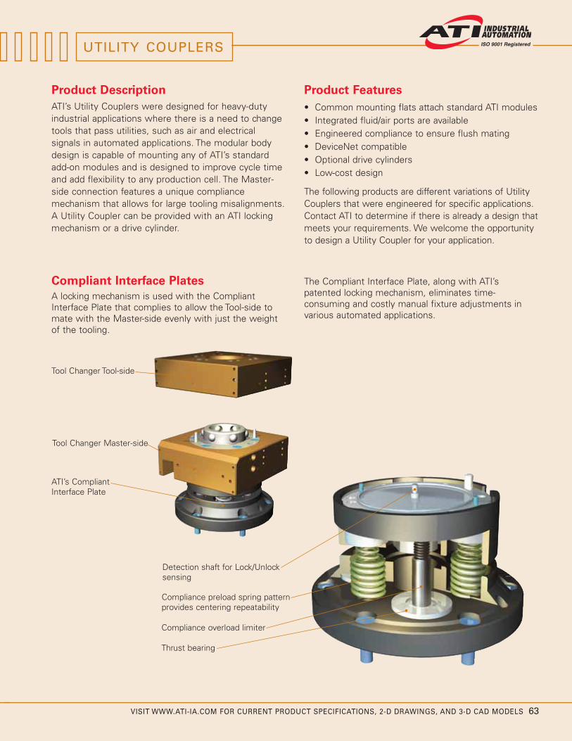
VISIT WWW.ATI-IA.COM FOR CURRENT PRODUCT SPECIFICATIONS, 2-D DRAWINGS, AND 3-D CAD MODELS 63
Product Description
ATI’s Utility Couplers were designed for heavy-dutyindustrial applications where there is a need to changetools that pass utilities, such as air and electricalsignals in automated applications. The modular bodydesign is capable of mounting any of ATI’s standardadd-on modules and is designed to improve cycle timeand add flexibility to any production cell. The Master-side connection features a unique compliancemechanism that allows for large tooling misalignments.A Utility Coupler can be provided with an ATI lockingmechanism or a drive cylinder.
Compliant Interface Plates
A locking mechanism is used with the CompliantInterface Plate that complies to allow the Tool-side tomate with the Master-side evenly with just the weightof the tooling.
Product Features
• Common mounting flats attach standard ATI modules• Integrated fluid/air ports are available• Engineered compliance to ensure flush mating • DeviceNet compatible• Optional drive cylinders • Low-cost design
The following products are different variations of UtilityCouplers that were engineered for specific applications.Contact ATI to determine if there is already a design thatmeets your requirements. We welcome the opportunityto design a Utility Coupler for your application.
The Compliant Interface Plate, along with ATI’spatented locking mechanism, eliminates time-consuming and costly manual fixture adjustments invarious automated applications.
Thrust bearing
Tool Changer Tool-side
Compliance overload limiter
Detection shaft for Lock/Unlocksensing
Compliance preload spring patternprovides centering repeatability
Tool Changer Master-side
ATI’s CompliantInterface Plate
UTILITY COUPLERS

64 VISIT WWW.ATI-IA.COM FOR CURRENT PRODUCT SPECIFICATIONS, 2-D DRAWINGS, AND 3-D CAD MODELS
UTILITY COUPLERS
G2 Compliant Utility Coupler
The G2 Compliant Utility Coupler meets theaggressive demands of changing tooling for framinggates. The Master-side features an optional guidedcylinder to provide the coupling force, and a uniquecompliance swivel joint that allows for severemisalignment of the Tool-side prior to coupling. Thereare also two optional 3/4 NPT self-sealing portsintegrated into the body of the coupler.
The rectangular body shape allows for easy mountingof additional peripheral utility modules, such asDeviceNet, Fluid/Air, or Electrical. Because this couplerdoes not have a locking mechanism, it offers greaterflexibility enabling reduced tooling costs and cycle time.Other port, compliance, and size options are available.Contact ATI for more information.
Optional drivecylinder
Drive cylinderProx. sensor
Center swivel bearing
Thrust bearing
Compliance overload limiter
Hardened steelalignment pin
Compliance preloadspring pattern providescentering repeatability
(2) 3/4 NPT self-sealing airconnections
Master- and Tool-sidesfeature up to (4)mounting flats forpassing utilities
(2) 3/4 NPTconnections
GA2 Utility Coupler
The GA2 Utility Coupler is a simple, economic couplerthat features (10) integrated 3/8 NPT air ports, heavy-duty alignment features, and (2) mounting flats to attachadditional utility modules (R19 electrical module shownattached as an example).
The GA2's mounting pattern is symmetrical, whichallows for right-hand and left-hand mounting. Thecoupler is also compatible with our series of guidedcylinders. The simple design also offers greater flexibilityenabling reduced tooling costs and cycle time.
Optional Tool- and Master-sideelectrical modules
(10) 3/8 NPT threadedconnections
Alignment bins
Aluminum body
(4) Symmetric mountinghole patterns

VISIT WWW.ATI-IA.COM FOR CURRENT PRODUCT SPECIFICATIONS, 2-D DRAWINGS, AND 3-D CAD MODELS 65
C5C Compliant Electrical Module
ATI Industrial Automation has developed a new line ofelectrical modules that are compliant in the X, Y, and Zdirections for those demanding manual tool couplerapplications. The C5C Compliant Electrical Module
features a 5 pin, 5 amp capability with custom length,pre-wired cable connectors. Other versions areavailable. The unit features a patent-pending compliancefeature that allows the pin block to float inside itshousing, guaranteeing a reliable connection, even inextreme end-effector loading conditions.
The C5C series of electrical modules can mount to anybayonet-style tool changer and can be custom-designedto fit your specific application.
Initially developed for bayonet -style manual tool changeapplications, compliant electrical modules that featurethe new self-centering compliance feature are seeing anincreasing demand. ATI's Engineering department, thelargest of its kind for an end-effector company, canquickly design a custom compliant module to fit yourapplication.
Tool-side housing
Bayonet couplerTooling mount
Tool-sidecustomer-specifiedelectrical connection
Master-sidecustomer-specifiedelectrical connection
Master-side fixed outer housing
Master-sidefloating inner housing
Pre-alignment ears
Robot mount
5 conductor pin block

66 VISIT WWW.ATI-IA.COM FOR CURRENT PRODUCT SPECIFICATIONS, 2-D DRAWINGS, AND 3-D CAD MODELS
SPECIAL APPLICATION TOOL CHANGERS
QC-25 Tool Changer with 34 Pass-through Ports
The QC-25 Tool Changer was designed for a 34 pound(15.1 kg) payload. It has a small 4.7 inch (120 mm)outer diameter and features (26) M5 air connections,and (8) 1/8 BSPP (G) threaded connections. The QC-25also features a mounting flat for the attachment ofadditional electrical modules.
QC-25 Master and Tool
The following are a select few of the special application Tool Changers that ATI’s engineering team has created.ATI is dedicated to developing cost-effective, state-of-the-art products and solutions that improve roboticproductivity. We welcome the opportunity to design a Tool Changer for your application.
QC-62 Square Body Tool Changer forNon-robotic Fixture Docking
The QC-62 is a small square body Tool Changerdesigned for docking fixtures in severe plantconditions. It can accept ATI DeviceNet modules, andallows for 160 pound (72.6 kg) payloads. The QC-62 isonly 5.25 inches (133 mm) square, and also featuresoptional air blow-off modules and attachment of anoptional compliant interface plate.
QC-73 Custom Rail Changer
The QC-73 Tool Changer features a 4.6 inch (117 mm)square body, Lock/Unlock and Ready-to-Lock sensing,and allows for the attachment of a specialized utilitymodule that passes self-sealing air, as well aselectrical signals. These utilities are passed along theaxis of the Tool Changer allowing for simple hoserouting. The QC-73 features a custom squaremounting pattern, and allows for 180 pound (81.6 kg)payloads.
QC-35 Through-Hole Changer
The QC-35 Tool Changer uses a 3-locking mechanismdesign to allow a 1.77 inch (45 mm) diameter through-hole that is sealed when coupled. Allowing for amaximum 100 pound (45.4 kg) payload, this small ToolChanger is only 6 inches (152 mm) in diameter and alsoallows for the mounting of up to two additional utilitymodules. QC-35 Master and Tool
QC-62 Master and Tool with DeviceNet Modules
QC-73 Master and Tool

VISIT WWW.ATI-IA.COM FOR CURRENT PRODUCT SPECIFICATIONS, 2-D DRAWINGS, AND 3-D CAD MODELS 67
QC-220 Electric Tool Changer
The QC-220 Electrically-Actuated Tool Changer from ATI(patents pending) was designed for heavy-dutyapplications where air supply is either not available ornot desired. The low-voltage, low-current inputs allowfor easy integration into electric body shops. Virtuallythe same size as the existing QC-210 series pneumaticversion, this electric version Master mates with pre-existing QC-210 Tool-side plates. The Electric ToolChanger also features up to five accessory modulemounting flats for demanding material handling orservo welding applications.
QC-220 Master and Tool
QC-80 Tool Changer for LightweightServo Welding
The QC-80 was developed for lightweight servo weldingapplications. Its compact design features integrated,square robot mounting patterns and internalLock/Unlock and Ready-to-Lock sensors. The newlightweight locking mechanism allows for 180 pound(81.6 kg) payloads. Lightweight weld current, servo, andfluid modules were also developed for this application.Entire package weighs only 13.2 pounds (6 kg).
QC-203 “H” Body Tool Changer
The QC-203 “H” Body Tool Changer was developed foran application that required the mounting of up to sixutility modules. It allows for 450 pound (204 kg)payloads and is compatible with ATI Heavy AutomationDeviceNet modules. The QC-203 also features (4) 1/4NPT pass-through air ports and internal Lock/Unlockand Ready-to-Lock sensing.
QC-80 Master and Tool
QC-203 Master and Tool
QC-76 Lightweight Tool Changer
The QC-76 Tool Changer features a lightweightpackage of only 8.15 pounds (3.7 kg) while allowing for240 pound (108.9 kg) payloads. It features (5) 3/8 NPTpass-through air connections and a stack height ofonly 2.56 inches (65 mm). The QC-76 also featuresinternal Lock/Unlock and Ready-to-Lock sensing.
QC-76 Master and Tool

Other ATI Products
Robotic Collision Sensor
Designed to prevent damage to robotic end-effectors resulting from robot crashes. Featuresinclude: Automatic reset, high-repeatability, andlarge moment rotation.
Robotic and CNC Deburring Tools
These air-driven robotic tools cover a wide variety ofautomated deburring and finishing applications withfast cycle times and clean, accurate cuts. TheRadially-Compliant Deburring Tool is designed forremoval of parting lines and flash. The Axially-Compliant Deburring Tool is specially designed foredge deburring and chamfering. The Axially-Compliant Finishing Tool is designed for materialfinishing operations on aluminum, plastic, steel, andmore.
Robotic Rotary Joint
A device that allows unlimited rotation of end-of-armtooling without tangling or twisting robot tooling utilitylines. Utilizes advanced slip-ring technology to passelectrical and pneumatic signals from robot totooling.
Multi-Axis Force/Torque Sensor
Measures the full six components of force andtorque. High overload protection and high signal-to-noise ratio. Used in robotic and research applications.
Automated Assembly Alignment Device
An insertion device using Remote CenterCompliance technology that helps assemblymachines automatically align close-fitting parts, preventing jamming and galling.
Company Profile
ATI Industrial Automation is a world-leading developer of Automatic Tool Changers, Multi-AxisForce/Torque Sensing Systems, Compliance Devices,Robotic Collision Sensors, Robotic Deburring Tools,and Robotic Rotary Joints. Our products are foundin thousands of successful applications around theworld.
Since 1982, our engineers have been developingcost-effective, state-of-the-art products and solutionsto improve manufacturing productivity.
Our Mission is to provide customers around theworld with high-quality robotic peripheral devices,tooling, and sensors that enhance customerprofitability by increasing the effectiveness,flexibility, safety, and productivity of their automationapplications. We accomplish this through continuousimprovement of existing products, productcustomization, and new product innovation.
Our engineering-centric staff focuses on providingcustomer solutions to robotic, automation, andsensing applications.
Our Quality Policy
ATI Industrial Automation strives to providecustomer satisfaction through continual improvementof on-time delivery, quality and reliability, and a constant focus on innovation and profitability.
© Copyright by ATI Industrial Automation, Inc. 2009. All rights reserved. DeviceNet and ODVA are registered trademarks of Open DeviceNet Vendors Association, Inc.PROFIBUS and PROFINET are registered trademarks of PROFIBUS International. INTERBUS is a registered trademark of Phoenix Contact GmbH. EtherNet/IP is a registered trademark of ControlNet International Ltd. used under license by ODVA.
9205-20-1004-08 March, 2009
Pinnacle Park1031 Goodworth DriveApex, NC 27539 USA
+1 919.772.0115 +1 919.772.8259 faxE-mail: [email protected]