robotics club (rtist)
TRANSCRIPT

7/29/2019 Robotics club (Rtist)
http://slidepdf.com/reader/full/robotics-club-rtist 1/26
Developed by:Aamir saddam
Abhishek rajan
R-TIST CLUB NITJ
7/29/2019 Robotics club (Rtist)
http://slidepdf.com/reader/full/robotics-club-rtist 2/26
TRANSPORTER
Description
A robotic arm is a robotic manipulator, with similar
functions to a human arm .motor is used for joint
rotation. It has about same number of degree of
freedom as in human arm. Humans pick things up
without thinking about the steps involved. In order
for a robot or a robotic arm to pick up or move
something, someone has to tell it to performseveral actions in a particular order — from moving
the arm, to rotating the “wrist” to opening and
closing the “hand” or “fingers.”

7/29/2019 Robotics club (Rtist)
http://slidepdf.com/reader/full/robotics-club-rtist 3/26
For constructing manual robot-
Manual robot should have the feature of robotic
arm that can pick an object and place it on another
autonomous robot which will carry the object to
drop zone.
Overview-
Degree of freedom- 3
Payload Capacity (Fully Extended) -250 gm.
No. of motors required- 3 (D.C geared motor)
3 switches to control three motors
Chassis
Ciruit board for soldering 3 switches on board and connecting
the three switches to 3 motors.
Mechanical stand(clamp) for connecting different motors to
each other.
12 volt power supply. It can be reduced accordingly using
diodes and resistors

7/29/2019 Robotics club (Rtist)
http://slidepdf.com/reader/full/robotics-club-rtist 4/26
Base motor which is installed on chassis is generally selected of
low r. p.m as 10 rpm and can sustain upto 3 kg torque.in
human arm, this motor is just like our shoulder. This motor
gives up and down movement of the arm
Then second motor which is just like our elbow provides
second degree of freedom is generally selected of 30 rpm .This
motor gives left and and right motion to the arm.
Third motor is used as jaw to grab the object tightly and lift it. It
is generally selected of 60 rpm.
Chassis D.C geared motor of 30 rpm

7/29/2019 Robotics club (Rtist)
http://slidepdf.com/reader/full/robotics-club-rtist 5/26
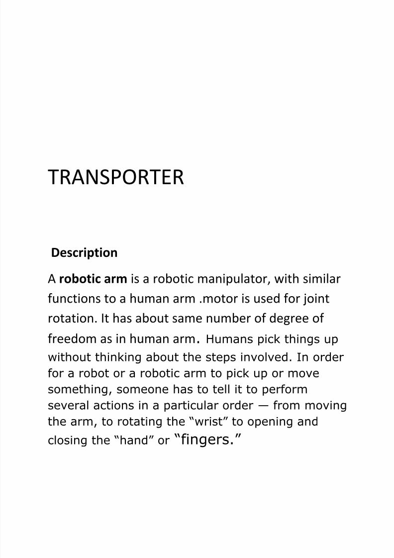
Switches- the wires of three motors are connected
to three switches .
We use bipolar switch having 6 pins as shown in the
figure . The middle two pins are connected to
power supply. The upper two pins is connected to
the motor which gives one specific direction . and
the lower two pins are connected to the motor with
opposite terminal, reverse to that of upper pins.It
rotates the motor in reverse direction.
7/29/2019 Robotics club (Rtist)
http://slidepdf.com/reader/full/robotics-club-rtist 6/26
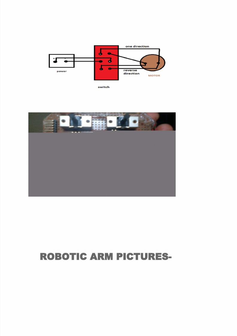
ROBOTIC ARM PICTURES-

7/29/2019 Robotics club (Rtist)
http://slidepdf.com/reader/full/robotics-club-rtist 7/26

7/29/2019 Robotics club (Rtist)
http://slidepdf.com/reader/full/robotics-club-rtist 8/26

7/29/2019 Robotics club (Rtist)
http://slidepdf.com/reader/full/robotics-club-rtist 9/26
Line Following Robot
A line follower is an autonomous bot that can
follow a specific colored line painted on a surface of
different contrast, such as white on black.
To start with first of all I will be discussing a small
concept of light. I believe you all know that the light
that strikes any platform is reflected. The reflection
and absorption coefficient of light depend upon
material, color of platform and other factors. In
simple words the black surface absorbs the light andthe white surface reflects it, this is the basic
concept behind making a line follower.
7/29/2019 Robotics club (Rtist)
http://slidepdf.com/reader/full/robotics-club-rtist 10/26
So the line follower has an emitter and a reflector.
The reflector receives the light and generates a
voltage proportional to the intensity of the light, if
this voltage is above a threshold it means SIGNAL=1
(logic one) else SIGNAL= 0 (logic zero).
Let’s take up an example where we have to move our
bOt on black surface having white line. Suppose I
have two Infra Red (IR) sensor pairs that are on
different halves of a bOt with respect to geometrical
central axis of the bOt. The sensors are placed in
such a way that the white line lies in between both
the sensors when the bOt is placed on the white
track painted on black surface to move. Now if the
white line is between both the sensors while moving
forward both the sensors will be on black surface
and the detectors/receivers will receive less amount
of light since black absorbs light and hence signal
provided by both the infra-red receivers will be low.
7/29/2019 Robotics club (Rtist)
http://slidepdf.com/reader/full/robotics-club-rtist 11/26
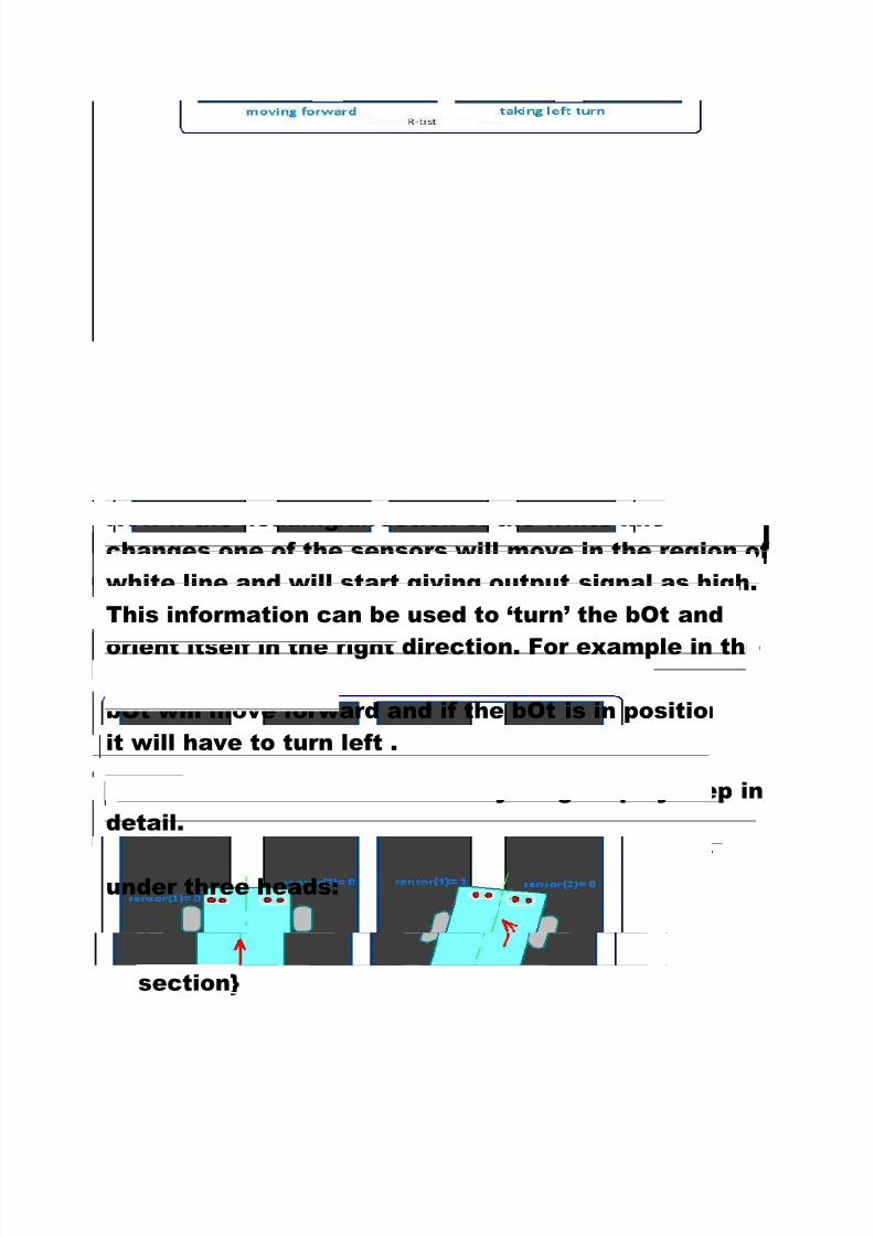
Now if the heading/direction of the white line
changes one of the sensors will move in the region of
white line and will start giving output signal as high.
This information can be used to ‘turn’ the bOt and
orient itself in the right direction. For example in theabove figure if the bot is located in position 1, then
bOt will move forward and if the bOt is in position 2
it will have to turn left .
Let’s move on and discuss everything step by step in
detail.
We will be discussing the making of line follower under three heads:
1. Chassis of robot { those familiar can skip this
section}

7/29/2019 Robotics club (Rtist)
http://slidepdf.com/reader/full/robotics-club-rtist 12/26
2. Electronics/Hardware Designing
3. Programming/Software Designing
CHASSIS OF ROBOT
1. Base of robot: The base or the material of the
platform of robot can be made with any easily
available material like switch board, wood, acrylic
sheet or steel sheet. As our robot will be very light,
you don’t have to think a lot about strength and other
such factors. We recommend you to make a small
size and light weight bOt. Here we are using steel
base:
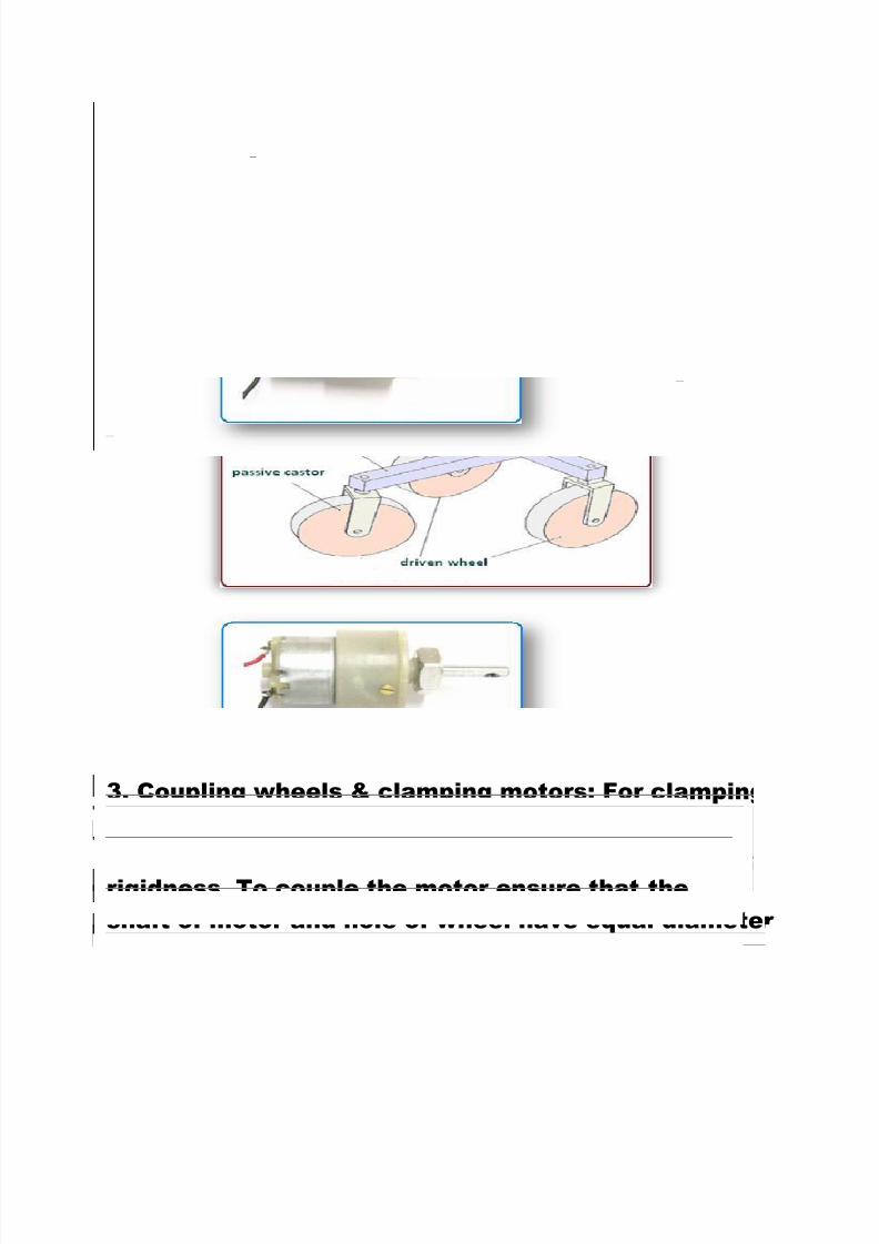
2. Motors and Driving Mechanism:
1. We will need a set of two motors that have same
rpm (revolution per minute).
2. We will be using differential drive for maneuvering
our bOt i.e. we will have three wheelsfor our bOt,

7/29/2019 Robotics club (Rtist)
http://slidepdf.com/reader/full/robotics-club-rtist 13/26
the front two will be powered and the rear will be
free wheel.
3. When the bot is moving straight both the motors
should have equal speed.4. For turning, one of the motor is switched off. If we
switch off the left motor, the bot will turn left and
vice versa.
1. You can choose a motor of rpm around 100 and a
torque of 1kg-cm
7/29/2019 Robotics club (Rtist)
http://slidepdf.com/reader/full/robotics-club-rtist 14/26
3. Coupling wheels & clamping motors: For clamping
the motors you can use pipe clamps or make right
angled clamps. The right angle clamps ensure more
rigidness. To couple the motor ensure that the
shaft of motor and hole of wheel have equal diameter
(if you can’t find one check the tutorial on wheels).

7/29/2019 Robotics club (Rtist)
http://slidepdf.com/reader/full/robotics-club-rtist 15/26

7/29/2019 Robotics club (Rtist)
http://slidepdf.com/reader/full/robotics-club-rtist 16/26
ELECTRONICS
Below is a flow chart that explains the working of
the bOt:-
7/29/2019 Robotics club (Rtist)
http://slidepdf.com/reader/full/robotics-club-rtist 17/26
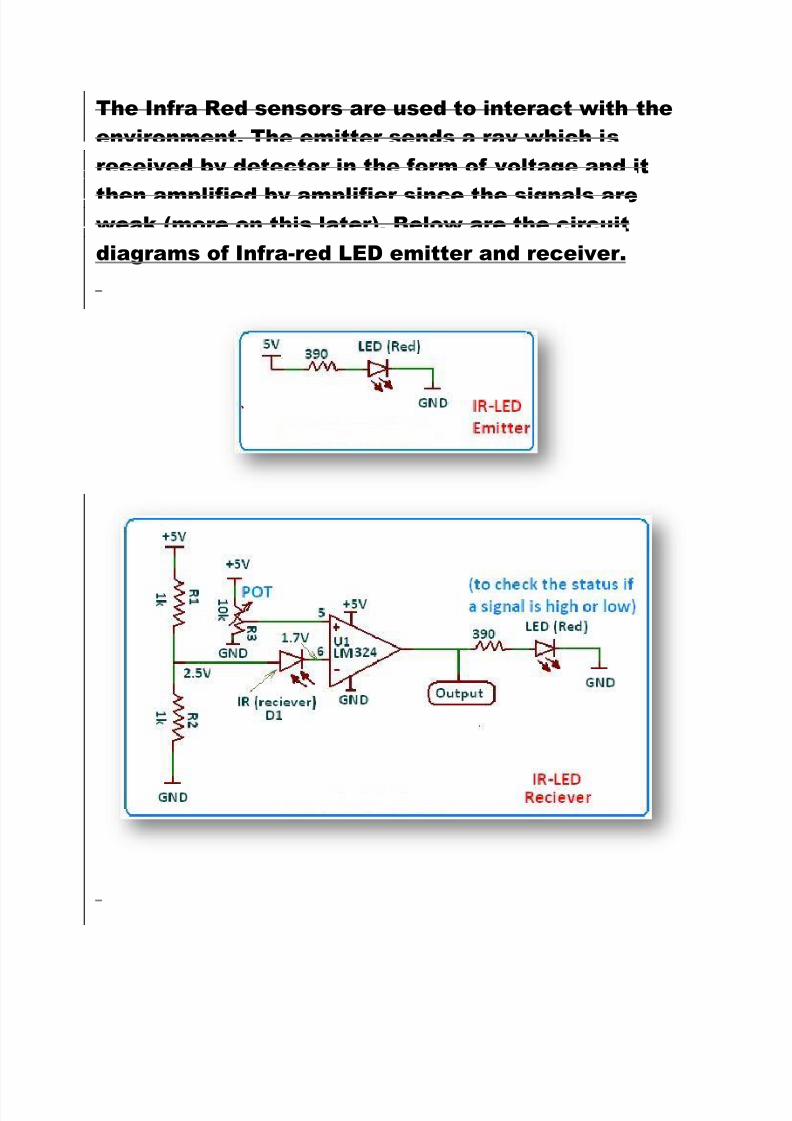
The Infra Red sensors are used to interact with the
environment. The emitter sends a ray which is
received by detector in the form of voltage and it
then amplified by amplifier since the signals areweak (more on this later). Below are the circuit
diagrams of Infra-red LED emitter and receiver.

7/29/2019 Robotics club (Rtist)
http://slidepdf.com/reader/full/robotics-club-rtist 18/26
Op-Amplifier (LM324)
If the rays received by the IR- LED receiver are above
a particular threshold then an amplified signal isgenerated by the amplifier (LM324). Note that the
sensors cannot directly send a signal to the
microcontroller as the signal voltage generated by
them is too low and even when sensors are on white
surface signal generated by them will interpreted
low by the microcontroller.
7/29/2019 Robotics club (Rtist)
http://slidepdf.com/reader/full/robotics-club-rtist 19/26
Microcontroller (AT89S52)
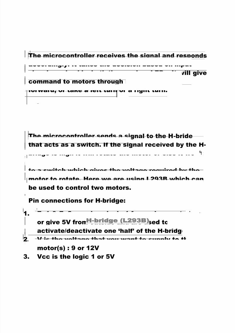
The microcontroller receives the signal and respondsaccordingly. It takes the decision based on input
signal received by both the receiver LEDs. It will give
command to motors through H-bridge to move
forward, or take a left turn or a right turn.
H-bridge (L293B)
The microcontroller sends a signal to the H-bride
that acts as a switch. If the signal received by the H-
bridge is high it will rotate the motor or else it won’t
do so. Note that microcontroller only sends a signal
to a switch which gives the voltage required by the
motor to rotate. Here we are using L293B which can
be used to control two motors.
Pin connections for H-bridge:
1. En1 & En2 are given logic 1 from microcontroller
or give 5V from outside and are used to
activate/deactivate one ‘half’ of the H-bridge.2. V is the voltage that you want to supply to the
motor(s) : 9 or 12V
3. Vcc is the logic 1 or 5V

7/29/2019 Robotics club (Rtist)
http://slidepdf.com/reader/full/robotics-club-rtist 20/26
The complete circuit diagram with all the integrated
circuits required for making a line follower is shown
below:-
7/29/2019 Robotics club (Rtist)
http://slidepdf.com/reader/full/robotics-club-rtist 21/26
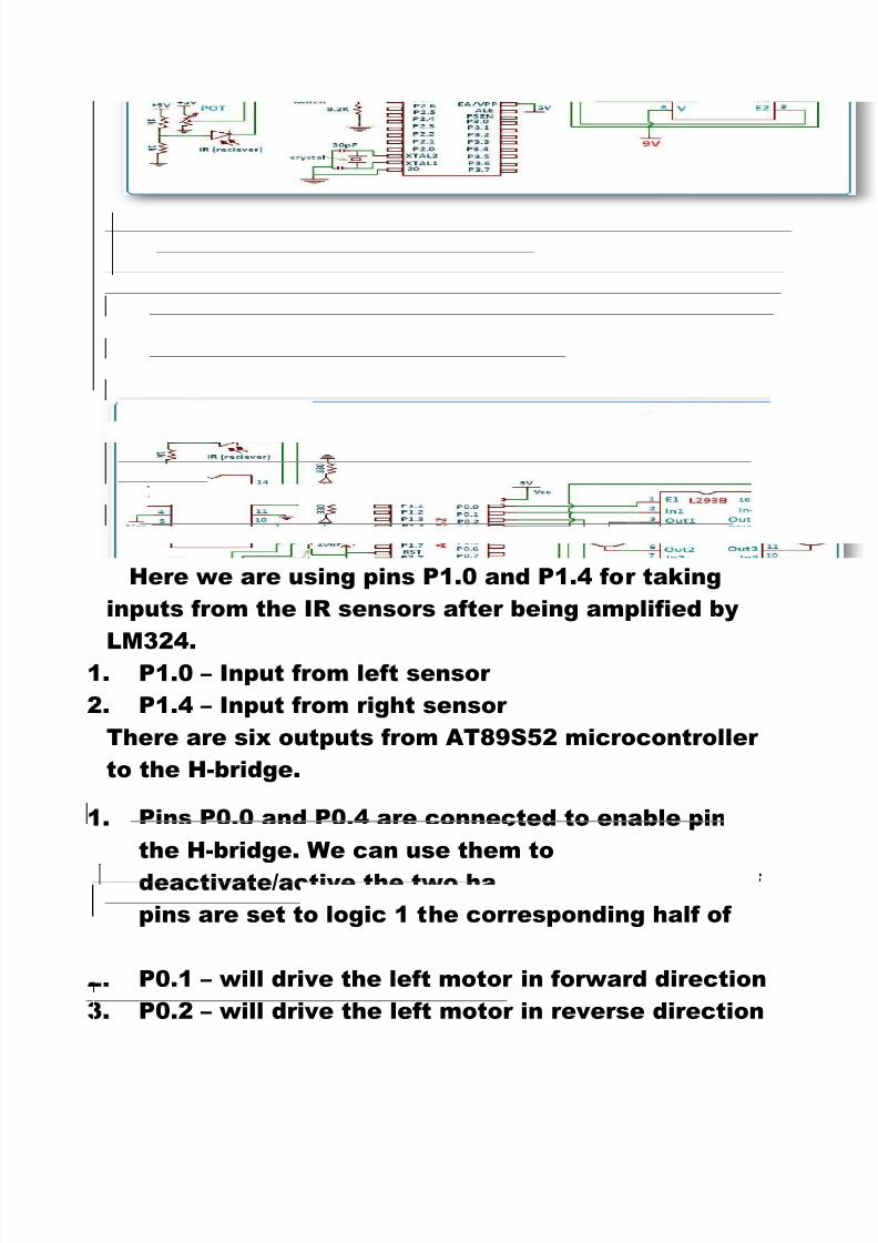
Here we are using pins P1.0 and P1.4 for taking
inputs from the IR sensors after being amplified by
LM324.1. P1.0 – Input from left sensor
2. P1.4 – Input from right sensor
There are six outputs from AT89S52 microcontroller
to the H-bridge.
1. Pins P0.0 and P0.4 are connected to enable pins of
the H-bridge. We can use them to
deactivate/active the two halves of H-bridge i.e. if
pins are set to logic 1 the corresponding half of
the H-bridge will be activated.
2. P0.1 – will drive the left motor in forward direction
3. P0.2 – will drive the left motor in reverse direction
7/29/2019 Robotics club (Rtist)
http://slidepdf.com/reader/full/robotics-club-rtist 22/26
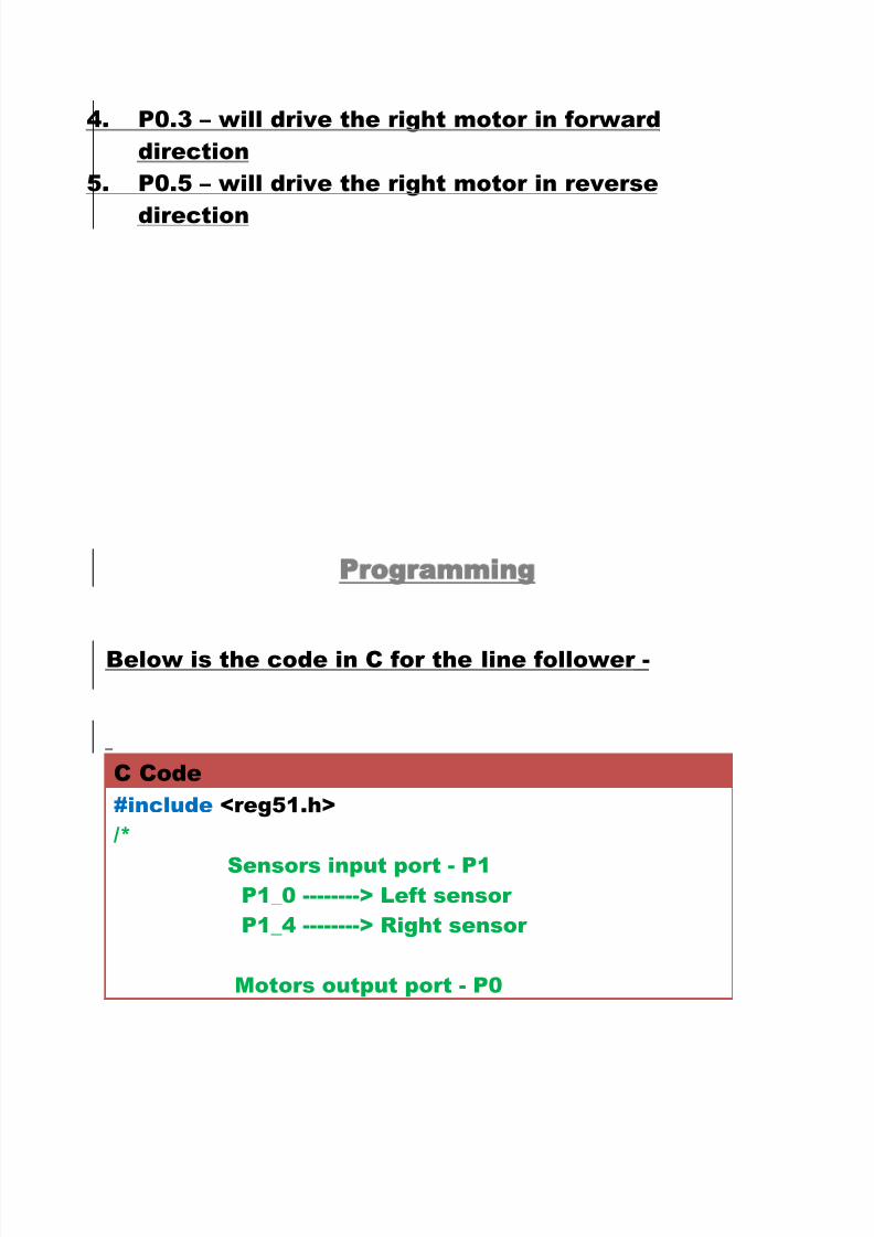
4. P0.3 – will drive the right motor in forward
direction
5. P0.5 – will drive the right motor in reverse
direction
Programming
Below is the code in C for the line follower -
C Code
#include <reg51.h>
/*
Sensors input port - P1 P1_0 --------> Left sensor
P1_4 --------> Right sensor
Motors output port - P0

7/29/2019 Robotics club (Rtist)
http://slidepdf.com/reader/full/robotics-club-rtist 23/26
P0_0 --------> Enable pin of the left half of
the H-bridge
P0_1 --------> will drive the left motor inforward direction
P0_2 --------> will drive the left motor in
reverse direction
P0_3 --------> will drive the right motor in
forward direction
P0_4 --------> Enable pin of the right half of
the H-bridge
P0_5 --------> will drive the right motor in
reverse direction
*/
/*Delay function runs an idle loop to create a time
delay. If the crystal used is of 11.0592 MHz then the
argument passed in delay is in 'milliseconds'.*/
void Delay(unsigned int itime)
{
unsigned int i,j;
for(i=0;i<itime;i++)
for(j=0;j<1275;j++); //Idle loop
}
void Forward() {
P0_1=1;
P0_2=0;
P0_3=1;
7/29/2019 Robotics club (Rtist)
http://slidepdf.com/reader/full/robotics-club-rtist 24/26
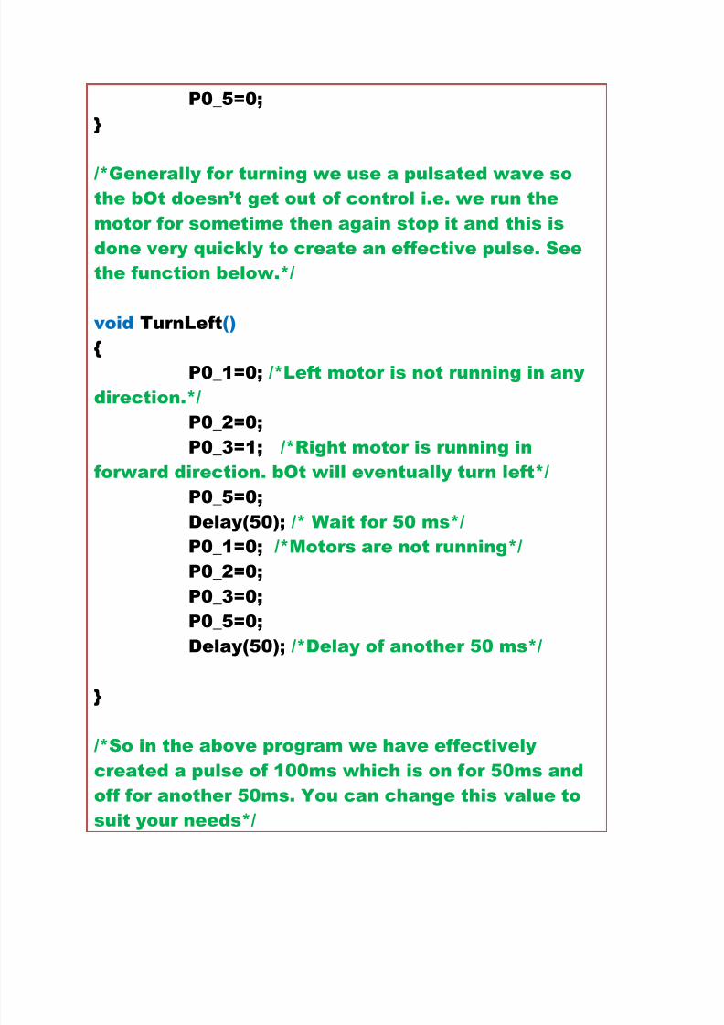
P0_5=0;
}
/*Generally for turning we use a pulsated wave sothe bOt doesn’t get out of control i.e. we run the
motor for sometime then again stop it and this is
done very quickly to create an effective pulse. See
the function below.*/
void TurnLeft()
{
P0_1=0; /*Left motor is not running in any
direction.*/
P0_2=0;
P0_3=1; /*Right motor is running in
forward direction. bOt will eventually turn left*/
P0_5=0;
Delay(50); /* Wait for 50 ms*/
P0_1=0; /*Motors are not running*/
P0_2=0;
P0_3=0;
P0_5=0;
Delay(50); /*Delay of another 50 ms*/
}
/*So in the above program we have effectively
created a pulse of 100ms which is on for 50ms and
off for another 50ms. You can change this value to
suit your needs*/
7/29/2019 Robotics club (Rtist)
http://slidepdf.com/reader/full/robotics-club-rtist 25/26
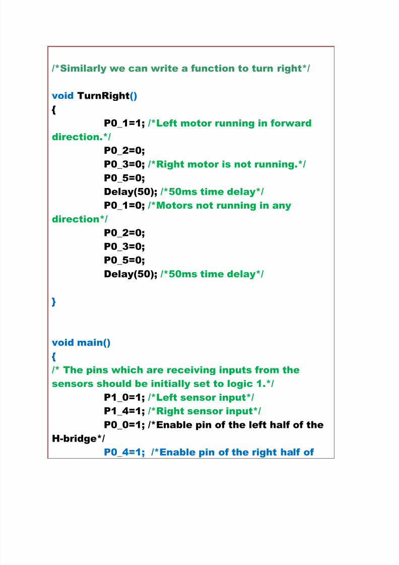
/*Similarly we can write a function to turn right*/
void TurnRight() {
P0_1=1; /*Left motor running in forward
direction.*/
P0_2=0;
P0_3=0; /*Right motor is not running.*/
P0_5=0;
Delay(50); /*50ms time delay*/
P0_1=0; /*Motors not running in any
direction*/
P0_2=0;
P0_3=0;
P0_5=0;
Delay(50); /*50ms time delay*/
}
void main()
{
/* The pins which are receiving inputs from the
sensors should be initially set to logic 1.*/
P1_0=1; /*Left sensor input*/ P1_4=1; /*Right sensor input*/
P0_0=1; /*Enable pin of the left half of the
H-bridge*/
P0_4=1; /*Enable pin of the right half of

7/29/2019 Robotics club (Rtist)
http://slidepdf.com/reader/full/robotics-club-rtist 26/26
the H-bridge*/
//main loop of the program
while(1){
if ((P1_0==0)&&(P1_4==1))
TurnRight();
else if ((P1_0==1)&&(P1_4==0))
TurnLeft();
else
Forward();
}
}
*************** THE END*************