robotics intelligent sensors (part 1)
TRANSCRIPT

RoboticsIntelligent sensors (part 1)
Tullio Facchinetti<[email protected]>
Tuesday 8th January, 2018
http://robot.unipv.it/toolleeo
Position sensors
position sensors allow the measurement of aposition or a displacement
• positions can be absolute or relative
• relative positions are measured by displacement sensors
Position sensors
position sensors are building blocks of many other sensors,such as velocity, acceleration, force, and pressure sensors
there are sensors to measure translational (linear) and rotationalpositions
several different technologies are used to build a position sensor:
• resistive (potentiometers)
• capacitive
• ultrasound (proximity sensors)
• inductive (linear variable differential transformer)
• optical (proximity sensor, photodiode array, laser Doppler)
• Hall effect
The potentiometer
xm
x t
Vs
V’0
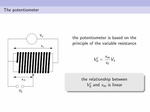
the potentiometer is based on theprinciple of the variable resistance
V ′0 =xmxt
Vs
the relationship betweenV ′0 and xm is linear
The potentiometer
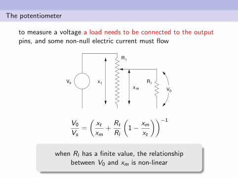
to measure a voltage a load needs to be connected to the outputpins, and some non-null electric current must flow
Vs x t
R t
xm
R l
V0
V0
Vs=
(xtxm
+Rt
Rl
(1− xm
xt
))−1
when Rl has a finite value, the relationshipbetween V0 and xm is non-linear
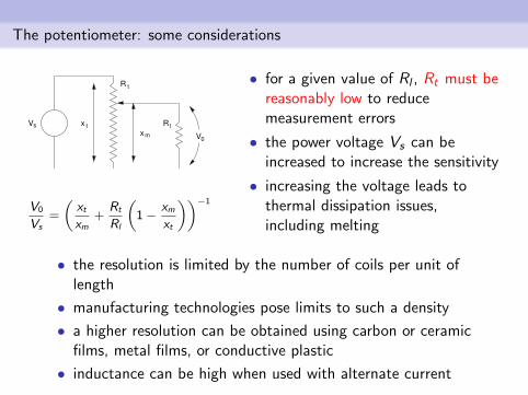
The potentiometer: some considerations
Vs x t
R t
xm
R l
V0
V0
Vs=
(xtxm
+Rt
Rl
(1− xm
xt
))−1
• for a given value of Rl , Rt must bereasonably low to reducemeasurement errors
• the power voltage Vs can beincreased to increase the sensitivity
• increasing the voltage leads tothermal dissipation issues,including melting
• the resolution is limited by the number of coils per unit oflength
• manufacturing technologies pose limits to such a density
• a higher resolution can be obtained using carbon or ceramicfilms, metal films, or conductive plastic
• inductance can be high when used with alternate current
The potentiometer: some observations
the main problem of the potentiometerarises at the contact point between
the sliding contact and the coil
• the contact wears, and it is sensible to environmental factorslike humidity and dirt
• the potentiometer is guaranteed for a given number of fullslidings (e.g., 10 millions)
• the lifetime strongly depends on the adopted material
• in case of quick movements, the contact may bounce, leadingto intermittent signals
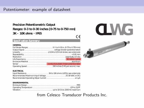
Potentiometer: example of datasheet
from Celesco Transducer Products Inc.
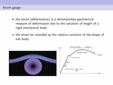
Strain gauge
• the strain (deformation) is a dimensionless geometricalmeasure of deformation due to the variation of length of arigid mechanical body
• the strain be intended as the relative variation of the shape ofone body
Strain gauge
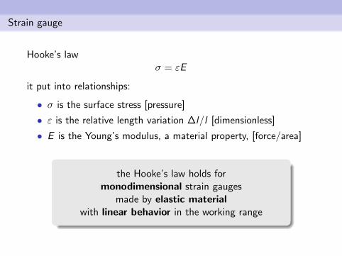
Hooke’s lawσ = εE
it put into relationships:
• σ is the surface stress [pressure]
• ε is the relative length variation ∆l/l [dimensionless]
• E is the Young’s modulus, a material property, [force/area]
the Hooke’s law holds formonodimensional strain gauges
made by elastic materialwith linear behavior in the working range
Strain gauge
d l
d h
l
w
h
top view
lateral view
d w
F
F
F
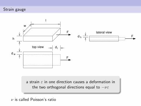
a strain ε in one direction causes a deformation inthe two orthogonal directions equal to −νε
ν is called Poisson’s ratio
Strain gauge: example
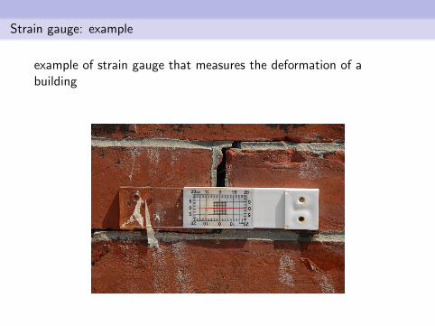
example of strain gauge that measures the deformation of abuilding
Strain and resistance
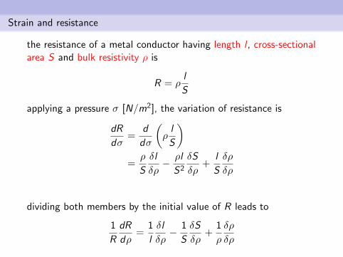
the resistance of a metal conductor having length l , cross-sectionalarea S and bulk resistivity ρ is
R = ρl
S
applying a pressure σ [N/m2], the variation of resistance is
dR
dσ=
d
dσ
(ρl
S
)=ρ
S
δl
δρ− ρl
S2
δS
δρ+
l
S
δρ
δρ
dividing both members by the initial value of R leads to
1
R
dR
dρ=
1
l
δl
δρ− 1
S
δS
δρ+
1
ρ
δρ
δρ
Strain and resistance
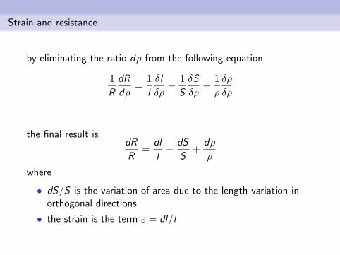
by eliminating the ratio dρ from the following equation
1
R
dR
dρ=
1
l
δl
δρ− 1
S
δS
δρ+
1
ρ
δρ
δρ
the final result isdR
R=
dl
l− dS
S+
dρ
ρ
where
• dS/S is the variation of area due to the length variation inorthogonal directions
• the strain is the term ε = dl/l
Strain and resistance
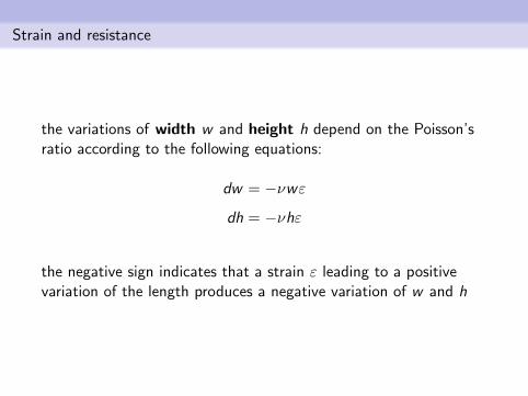
the variations of width w and height h depend on the Poisson’sratio according to the following equations:
dw = −νwε
dh = −νhε
the negative sign indicates that a strain ε leading to a positivevariation of the length produces a negative variation of w and h
Strain and resistance
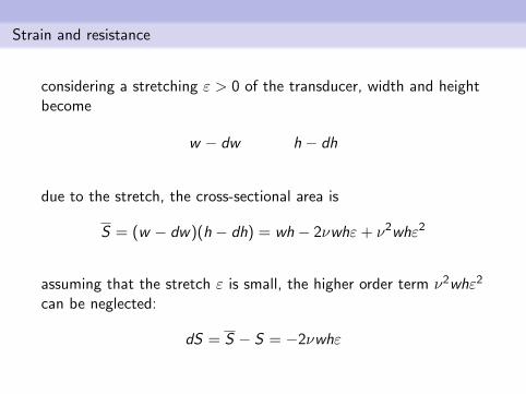
considering a stretching ε > 0 of the transducer, width and heightbecome
w − dw h − dh
due to the stretch, the cross-sectional area is
S = (w − dw)(h − dh) = wh − 2νwhε+ ν2whε2
assuming that the stretch ε is small, the higher order term ν2whε2
can be neglected:
dS = S − S = −2νwhε
Strain and resistance
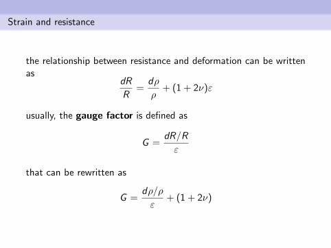
the relationship between resistance and deformation can be writtenas
dR
R=
dρ
ρ+ (1 + 2ν)ε
usually, the gauge factor is defined as
G =dR/R
ε
that can be rewritten as
G =dρ/ρ
ε+ (1 + 2ν)
Strain and resistance
the gauge factor is written in the following form
G =dρ/ρ
ε+ (1 + 2ν)
the formula puts the emphasis on two factors:
• a piezoresistive effect due to (dρ/ρ)/ε
• a geometric effect due to 1 + 2ν
by carefully selecting the building material, it is possibleto let one effect to dominate the other
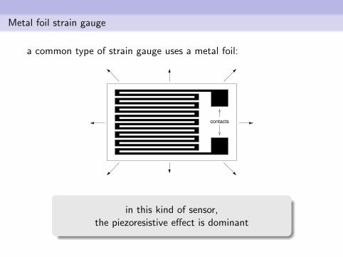
Metal foil strain gauge
a common type of strain gauge uses a metal foil:
contacts
in this kind of sensor,the piezoresistive effect is dominant
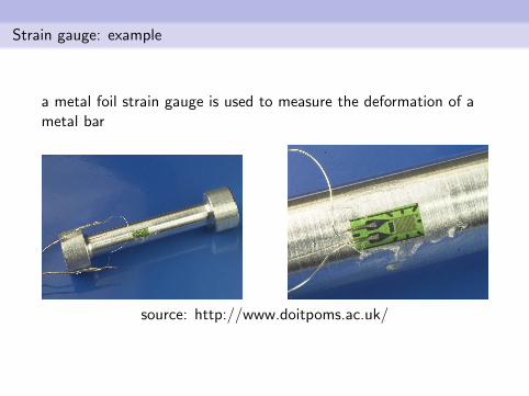
Strain gauge: example
a metal foil strain gauge is used to measure the deformation of ametal bar
source: http://www.doitpoms.ac.uk/
Capacitive sensors
position sensors based on capacities leverage the relationshipbetween capacitance and shape, dimension and permittivity ofthe material
the capacitance of a parallel plate capacitor is
C =ε0εrA
d
where
• ε0 is the free-space permittivity
• εr is the relative permittivity due to the dielectric material
• A is the area of the surface of plates
• d is the distance between plates
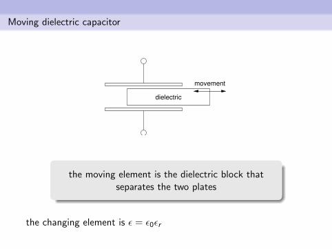
Moving dielectric capacitor
dielectric
movement
the moving element is the dielectric block thatseparates the two plates
the changing element is ε = ε0εr
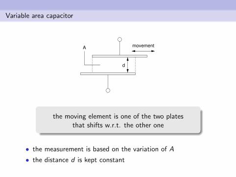
Variable area capacitor
d
movementA
the moving element is one of the two platesthat shifts w.r.t. the other one
• the measurement is based on the variation of A
• the distance d is kept constant
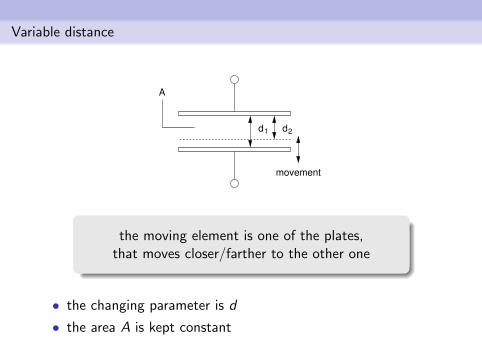
Variable distance
d2d1
A
movement
the moving element is one of the plates,that moves closer/farther to the other one
• the changing parameter is d
• the area A is kept constant
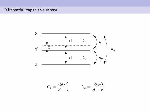
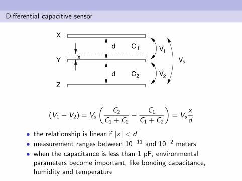
Differential capacitive sensor
C1
C2
V1
Vs
V2
d
d
Y
X
Z
x
C1 =ε0εrA
d − xC2 =
ε0εrA
d + x
Differential capacitive sensor
C1
C2
V1
Vs
V2
d
d
Y
X
Z
x
(V1 − V2) = Vs
(C2
C1 + C2− C1
C1 + C2
)= Vs
x
d
• the relationship is linear if |x | < d
• measurement ranges between 10−11 and 10−2 meters
• when the capacitance is less than 1 pF, environmentalparameters become important, like bonding capacitance,humidity and temperature
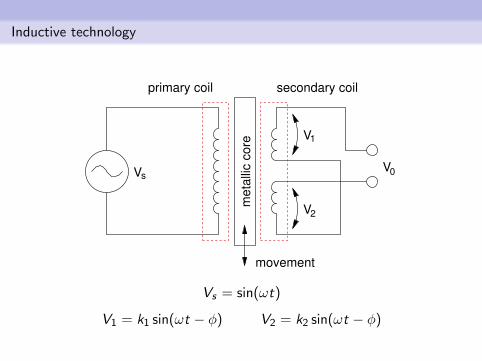
Inductive technology
secondary coilprimary coil
V
movement
V
V
V
me
talli
c c
ore
s
1
2
0
Vs = sin(ωt)
V1 = k1 sin(ωt − φ) V2 = k2 sin(ωt − φ)
Inductive technology
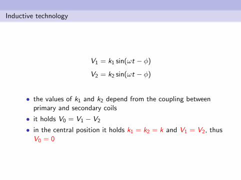
V1 = k1 sin(ωt − φ)
V2 = k2 sin(ωt − φ)
• the values of k1 and k2 depend from the coupling betweenprimary and secondary coils
• it holds V0 = V1 − V2
• in the central position it holds k1 = k2 = k and V1 = V2, thusV0 = 0
Inductive technology
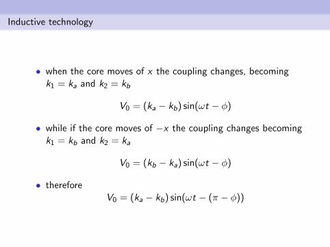
• when the core moves of x the coupling changes, becomingk1 = ka and k2 = kb
V0 = (ka − kb) sin(ωt − φ)
• while if the core moves of −x the coupling changes becomingk1 = kb and k2 = ka
V0 = (kb − ka) sin(ωt − φ)
• thereforeV0 = (ka − kb) sin(ωt − (π − φ))
Inductive technology: considerations
• can measure displacements from 100µm to 100 mm
• in practice, there is no friction
• lifetime up to 200 years
Angular position sensor
objective
measure the angular displacement of a body,which can usually rotate along one or more axis
applications:
• industrial robot motors control: the angular displacementof the motor shaft determine the positioning of the actuator
• motion speed of a mobile robot: from the angular positionof the motor shaft the angular speed can be inferred, and therobot motion can be tracked (usually with very low accuracy)
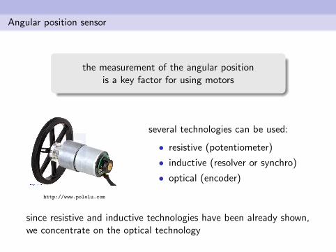
Angular position sensor
the measurement of the angular positionis a key factor for using motors
http://www.pololu.com
several technologies can be used:
• resistive (potentiometer)
• inductive (resolver or synchro)
• optical (encoder)
since resistive and inductive technologies have been already shown,we concentrate on the optical technology
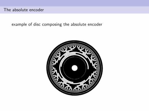
The absolute encoder
example of disc composing the absolute encoder
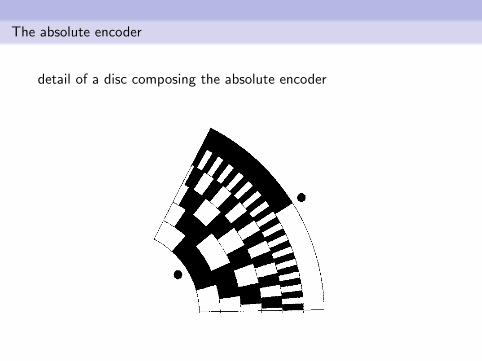
The absolute encoder
detail of a disc composing the absolute encoder
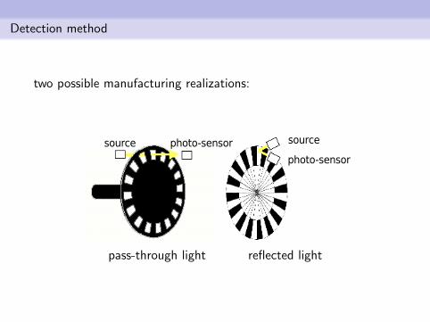
Detection method
two possible manufacturing realizations:
pass-through light reflected light
The absolute encoder
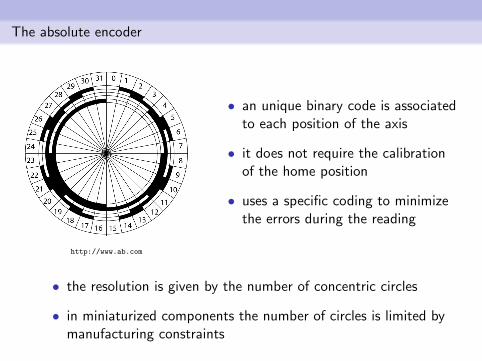
http://www.ab.com
• an unique binary code is associatedto each position of the axis
• it does not require the calibrationof the home position
• uses a specific coding to minimizethe errors during the reading
• the resolution is given by the number of concentric circles
• in miniaturized components the number of circles is limited bymanufacturing constraints
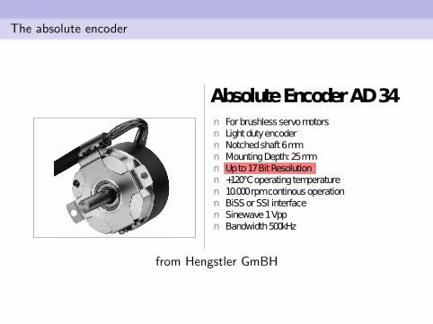
The absolute encoder
from Hengstler GmBH
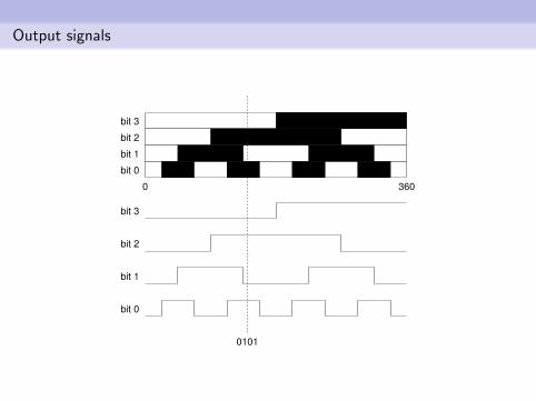
Output signals
3600
bit 0
bit 1
bit 2
bit 3
bit 3
bit 2
bit 1
bit 0
0101
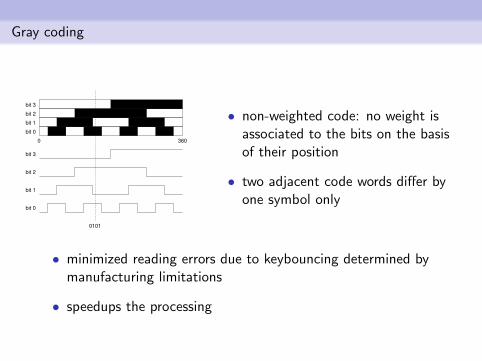
Gray coding
3600
bit 0
bit 1
bit 2
bit 3
bit 3
bit 2
bit 1
bit 0
0101
• non-weighted code: no weight isassociated to the bits on the basisof their position
• two adjacent code words differ byone symbol only
• minimized reading errors due to keybouncing determined bymanufacturing limitations
• speedups the processing
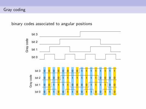
Gray coding
binary codes associated to angular positionsG
ray c
od
e
bit 1
bit 0
bit 2
bit 3
Gra
y c
ode
bit 1
bit 0
bit 2
bit 3 0
0
0
0
0 0 0 0 0 0 0
0 0 0 0 0 0 0
0 0
0000000
0 0 0 00
11 1
1 1 1
1 1 1 1 1 1 1 1
11 1 1
1 1 111111
1 1 1 111
1
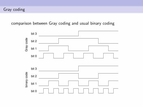
Gray coding
comparison between Gray coding and usual binary codingG
ray c
od
e
bit 1
bit 0
bit 2
bit 3
bit 0
bit 1
bit 2
bit 3
bin
ary
co
de
Gray coding
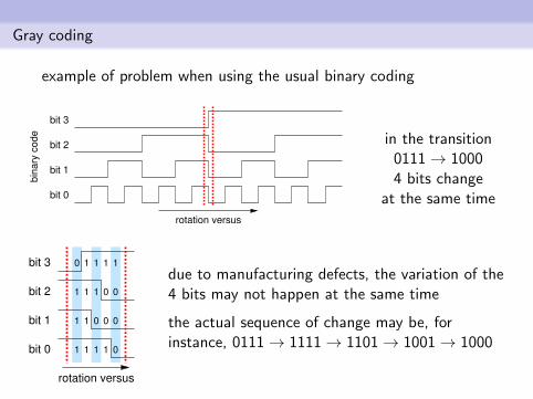
example of problem when using the usual binary coding
bit 0
bit 1
bit 2
bit 3
bin
ary
code
rotation versus
in the transition0111→ 10004 bits change
at the same time
bit 0
bit 1
bit 2
bit 3 0
1
1
1
1
1
1
1 1
0
1
1
1
0
0
1
0
0
0
1
rotation versus
due to manufacturing defects, the variation of the4 bits may not happen at the same time
the actual sequence of change may be, forinstance, 0111→ 1111→ 1101→ 1001→ 1000
Gray coding
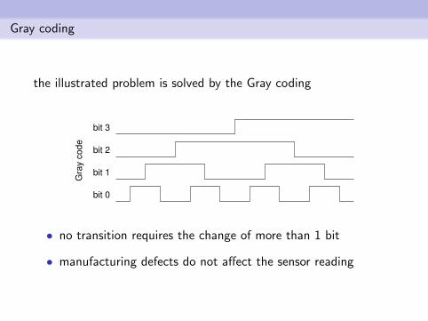
the illustrated problem is solved by the Gray codingG
ray c
od
e
bit 1
bit 0
bit 2
bit 3
• no transition requires the change of more than 1 bit
• manufacturing defects do not affect the sensor reading
The incremental encoder
• no unique codes are assigned to the shaft position
• allows to track both clockwise and anti-clockwise rotations
• requires the calibration of the home position
• suitable for high rotation speeds
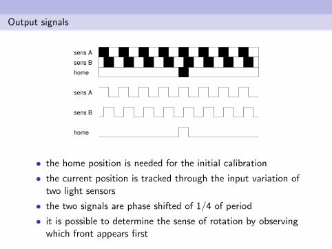
Output signals
sens A
sens B
home
sens A
sens B
home
• the home position is needed for the initial calibration
• the current position is tracked through the input variation oftwo light sensors
• the two signals are phase shifted of 1/4 of period
• it is possible to determine the sense of rotation by observingwhich front appears first
The gyroscope
measures the angular position or speedof a body rotating on its axis
gyros can use different building technologies:
• mechanical
• optical
• integrated circuits (MEMS)
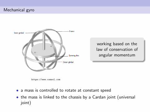
Mechanical gyro
https://www.comsol.com
working based on thelaw of conservation of
angular momentum
• a mass is controlled to rotate at constant speed
• the mass is linked to the chassis by a Cardan joint (universaljoint)
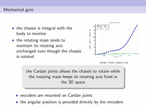
Mechanical gyro
• the chassis is integral with thebody to monitor
• the rotating mass tends tomaintain its rotating axisunchanged even though the chassisis rotated
https://www.comsol.com
the Cardan joints allows the chassis to rotate whilethe rotating mass keeps its rotating axis fixed in
the 3D space
• encoders are mounted on Cardan joints
• the angular position is provided directly by the encoders
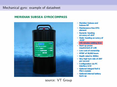
Mechanical gyro: example of datasheet
source: VT Group
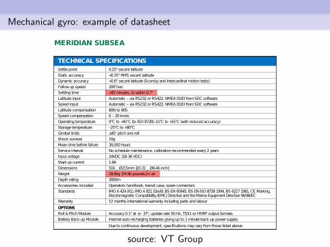
Mechanical gyro: example of datasheet
source: VT Group
Mechanical gyros: pros and cons
cons
• it has moving mechanical parts; the friction produces errors inthe measure and wearing of components
• special bearing and lubricating are needed to reduce thefriction, leading to bigger size, weight and cost
• the sensor must warm-up to let all the parts to reach thedilation required to work in proper conditions
pros
• the measure is stable: the rotating mass is able to keep alignedwith the global reference system better than every other gyro
Proximity sensors
open/close an electric circuit depending on theproximity of an object
some sensors may return the distance of the object
adopted technologies:
• infrared
• LASER
• capacitive
• inductive
• acoustic signals (ultrasound sensors)
Proximity sensors
applications:
• indutrial processes, to detect the presence or the position ofmachine parts or objects
• mobile robotics: obstacle avoidance, localization andmapping
• security: to detect open/close doors or windows
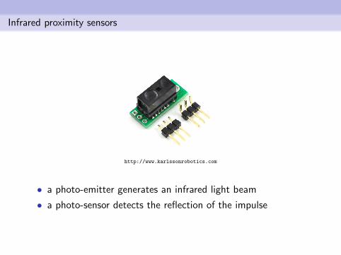
Infrared proximity sensors
http://www.karlssonrobotics.com
• a photo-emitter generates an infrared light beam
• a photo-sensor detects the reflection of the impulse
Infrared proximity sensors
possible disturbs caused by environmental illumination
to overcome the problem:
• some sensors modulate the signal to distinguish it from theenvironmental noise
• other sensors can infer the obstacle distance from the intensityof the perceived light
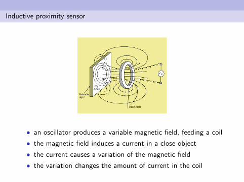
Inductive proximity sensor
• an oscillator produces a variable magnetic field, feeding a coil
• the magnetic field induces a current in a close object
• the current causes a variation of the magnetic field
• the variation changes the amount of current in the coil
Inductive proximity sensor
• working principle similar to the metal detector
• an electronic circuit measures the variation of current in thecoil
inductive sensors can only detectobjects made of metal
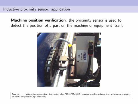
Inductive proximity sensor: application
Machine position verification: the proximity sensor is used todetect the position of a part on the machine or equipment itself.
Source: https://automation-insights.blog/2010/08/31/3-common-applications-for-discrete-output-inductive-proximity-sensors/
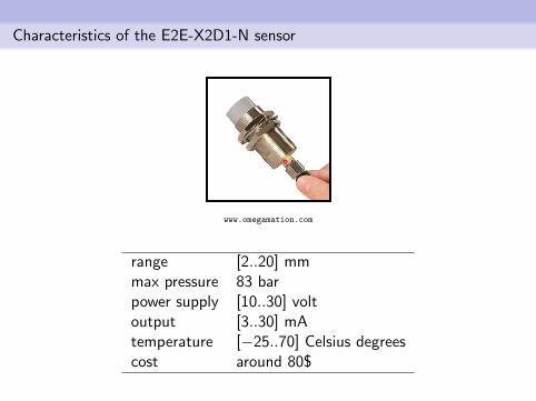
Characteristics of the E2E-X2D1-N sensor
www.omegamation.com
range [2..20] mmmax pressure 83 barpower supply [10..30] voltoutput [3..30] mAtemperature [−25..70] Celsius degreescost around 80$
Capacitive proximity sensors
• detect the variation of capacitance produced by an object
• a radio-frequency oscillator is connected to a metal plate
• when the plate gets close to an object the oscillationfrequency changes, detecting the object
capacitive sensors can only detectobjects made of metal
Ultrasonic sensor
• very useful for range detection in mobile robotics, togetherwith laser scanner and cameras
• the working principle is the same as SONARs (SOundNavigation And Ranging)
• active sonars emit the acoustic signal and detect the reflectedone
• working range up to 10 meters
• immune to electromagnetic noise
• can detect objects made of any material
• echo may not be detected in case of small objects ofunfavourable orientations
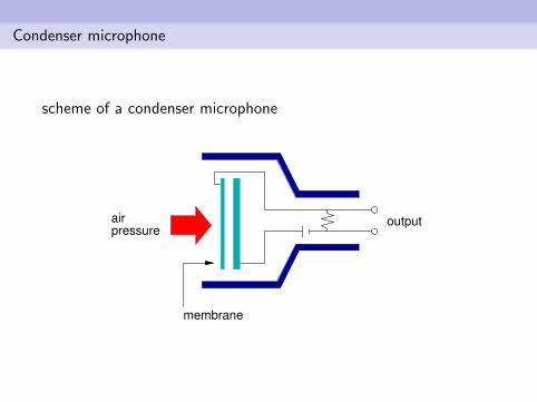
Condenser microphone
scheme of a condenser microphone
airpressure
membrane
output
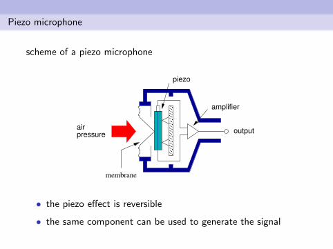
Piezo microphone
scheme of a piezo microphone
������������������������
������������������������
airpressure
membrane
piezo
amplifier
output
• the piezo effect is reversible
• the same component can be used to generate the signal
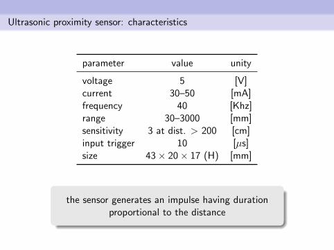
Ultrasonic proximity sensor: characteristics
parameter value unity
voltage 5 [V]current 30–50 [mA]frequency 40 [Khz]range 30–3000 [mm]sensitivity 3 at dist. > 200 [cm]input trigger 10 [µs]size 43× 20× 17 (H) [mm]
the sensor generates an impulse having durationproportional to the distance
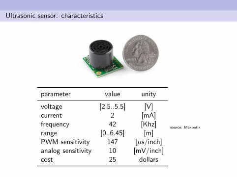
Ultrasonic sensor: characteristics
parameter value unity
voltage [2.5..5.5] [V]current 2 [mA]frequency 42 [Khz]range [0..6.45] [m]PWM sensitivity 147 [µs/inch]analog sensitivity 10 [mV/inch]cost 25 dollars
source: Maxbotix
Ultrasonic sensor
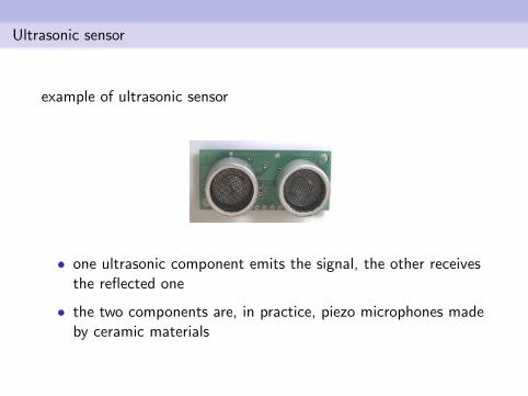
example of ultrasonic sensor
• one ultrasonic component emits the signal, the other receivesthe reflected one
• the two components are, in practice, piezo microphones madeby ceramic materials
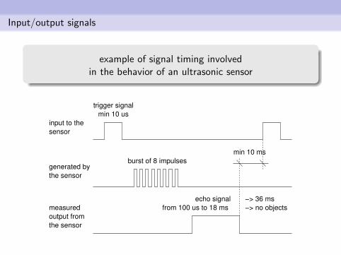
Input/output signals
example of signal timing involvedin the behavior of an ultrasonic sensor
measured
output from
the sensor
generated by
the sensor
input to the
sensor
trigger signal
min 10 us
burst of 8 impulses
echo signal
from 100 us to 18 ms
−> 36 ms
−> no objects
min 10 ms
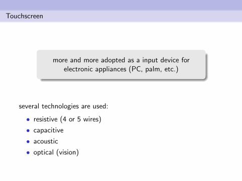
Touchscreen
more and more adopted as a input device forelectronic appliances (PC, palm, etc.)
several technologies are used:
• resistive (4 or 5 wires)
• capacitive
• acoustic
• optical (vision)
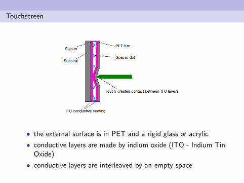
Touchscreen
• the external surface is in PET and a rigid glass or acrylic
• conductive layers are made by indium oxide (ITO - Indium TinOxide)
• conductive layers are interleaved by an empty space
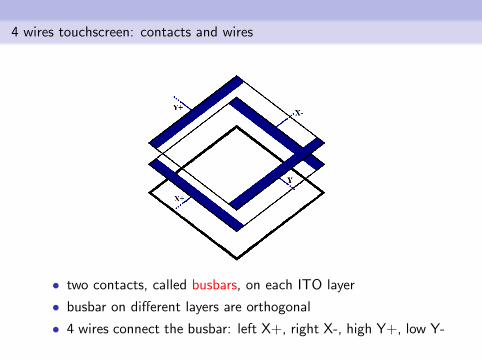
4 wires touchscreen: contacts and wires
• two contacts, called busbars, on each ITO layer
• busbar on different layers are orthogonal
• 4 wires connect the busbar: left X+, right X-, high Y+, low Y-
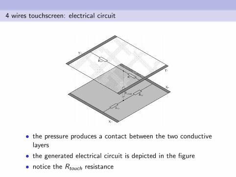
4 wires touchscreen: electrical circuit
• the pressure produces a contact between the two conductivelayers
• the generated electrical circuit is depicted in the figure
• notice the Rtouch resistance
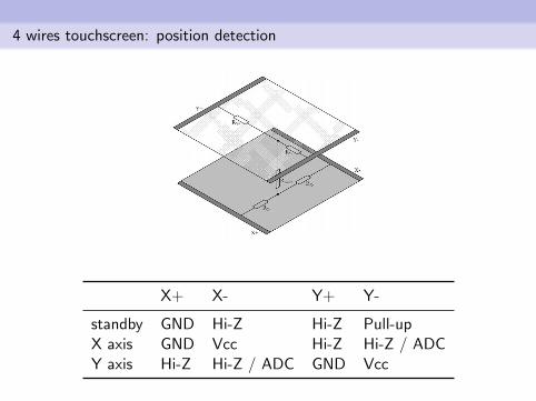
4 wires touchscreen: position detection
X+ X- Y+ Y-
standby GND Hi-Z Hi-Z Pull-upX axis GND Vcc Hi-Z Hi-Z / ADCY axis Hi-Z Hi-Z / ADC GND Vcc
Absolute position sensors
track the absolute position of a pointon the Earth surface
applications:
• navigation systems
• monitoring/tracking of motion (outdoor)
• distributed clock synchronization
GPS: Global Position System
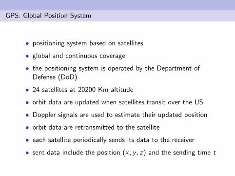
• positioning system based on satellites
• global and continuous coverage
• the positioning system is operated by the Department ofDefense (DoD)
• 24 satellites at 20200 Km altitude
• orbit data are updated when satellites transit over the US
• Doppler signals are used to estimate their updated position
• orbit data are retransmitted to the satellite
• each satellite periodically sends its data to the receiver
• sent data include the position (x , y , z) and the sending time t
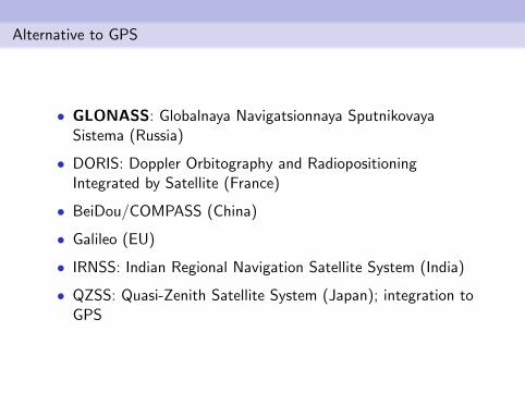
Alternative to GPS
• GLONASS: Globalnaya Navigatsionnaya SputnikovayaSistema (Russia)
• DORIS: Doppler Orbitography and RadiopositioningIntegrated by Satellite (France)
• BeiDou/COMPASS (China)
• Galileo (EU)
• IRNSS: Indian Regional Navigation Satellite System (India)
• QZSS: Quasi-Zenith Satellite System (Japan); integration toGPS
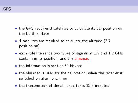
GPS
• the GPS requires 3 satellites to calculate its 2D position onthe Earth surface
• 4 satellites are required to calculate the altitude (3Dpositioning)
• each satellite sends two types of signals at 1.5 and 1.2 GHzcontaining its position, and the almanac
• the information is sent at 50 bit/sec
• the almanac is used for the calibration, when the receiver isswitched on after long time
• the transmission of the almanac takes 12.5 minutes
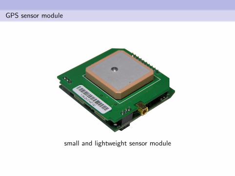
GPS sensor module
small and lightweight sensor module
GPS
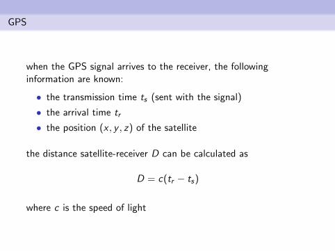
when the GPS signal arrives to the receiver, the followinginformation are known:
• the transmission time ts (sent with the signal)
• the arrival time tr
• the position (x , y , z) of the satellite
the distance satellite-receiver D can be calculated as
D = c(tr − ts)
where c is the speed of light
GPS
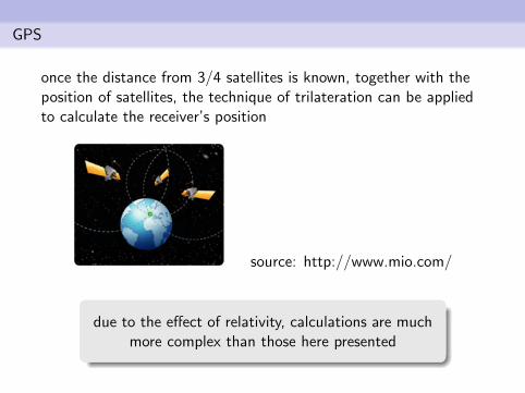
once the distance from 3/4 satellites is known, together with theposition of satellites, the technique of trilateration can be appliedto calculate the receiver’s position
source: http://www.mio.com/
due to the effect of relativity, calculations are muchmore complex than those here presented
Triangulation, trilateration, multilateration
there are different methods to calculate anunknown position starting from the positions of
known reference points
the following 3 methods are based on different parameters:
• triangulation: uses the distance from known locations andthe angles of lines connecting the receiver and the knownlocations
• trilateration: only the distance from known locations is used
• multilateration: based on the TDOA (Time Difference OfArrival), i.e., the time difference of the signal that is receivedby 3 or more receivers at known locations
Triangulation, trilateration, multilateration
the 3 methods require a travelling signal used todetect the distance between emitter and receiver
• in trilateration, the signals are emitted by the reference pointsat known positions and sensed by the point at unknownposition
• in multilateration, the signal is emitted by the point at theunknown location and it is received by the reference points
the transmitted signal is usually a radio signalor a sound (or ultra-sound) signal
Trilateration
r3
C3
C1
r1 r2
C2
Z=0
X
Y
(x,y,z)
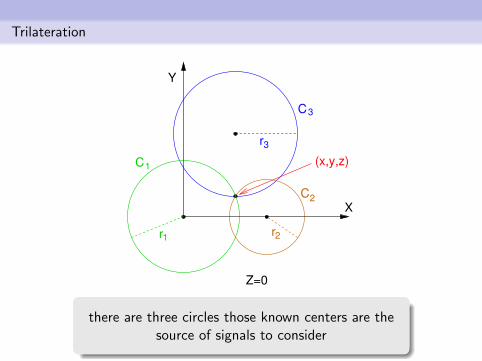
there are three circles those known centers are thesource of signals to consider
Trilateration
r3
C3
C1
r1 r2
C2
Z=0
X
Y
(x,y,z)
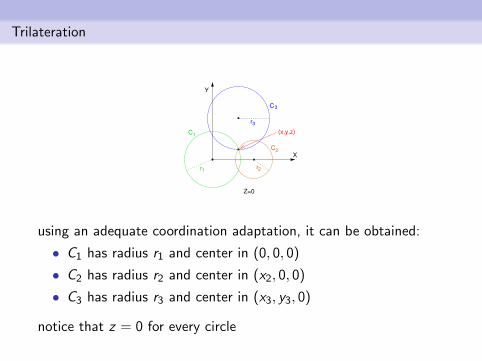
using an adequate coordination adaptation, it can be obtained:
• C1 has radius r1 and center in (0, 0, 0)
• C2 has radius r2 and center in (x2, 0, 0)
• C3 has radius r3 and center in (x3, y3, 0)
notice that z = 0 for every circle
Trilateration
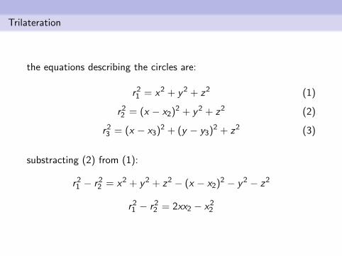
the equations describing the circles are:
r21 = x2 + y2 + z2 (1)
r22 = (x − x2)2 + y2 + z2 (2)
r23 = (x − x3)2 + (y − y3)2 + z2 (3)
substracting (2) from (1):
r21 − r22 = x2 + y2 + z2 − (x − x2)2 − y2 − z2
r21 − r22 = 2xx2 − x22
Trilateration
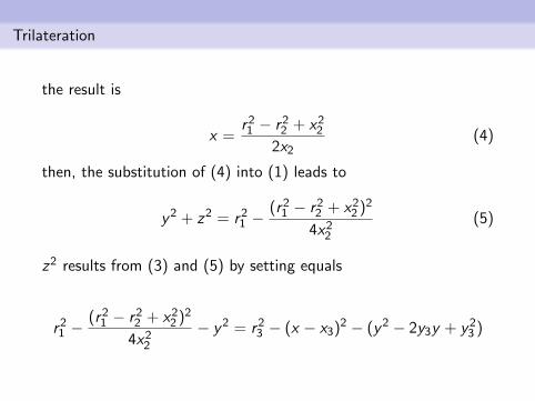
the result is
x =r21 − r22 + x22
2x2(4)
then, the substitution of (4) into (1) leads to
y2 + z2 = r21 −(r21 − r22 + x22 )2
4x22(5)
z2 results from (3) and (5) by setting equals
r21 −(r21 − r22 + x22 )2
4x22− y2 = r23 − (x − x3)2 − (y2 − 2y3y + y23 )
Trilateration
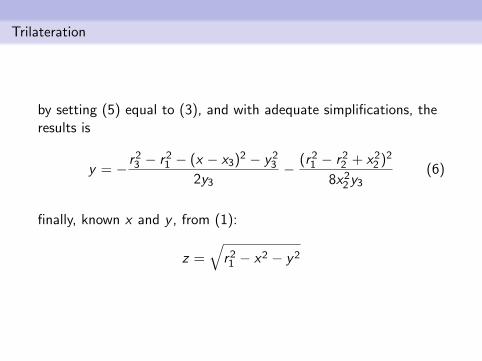
by setting (5) equal to (3), and with adequate simplifications, theresults is
y = − r23 − r21 − (x − x3)2 − y232y3
− (r21 − r22 + x22 )2
8x22y3(6)
finally, known x and y , from (1):
z =√r21 − x2 − y2
Multilateration
• based on the Time Difference Of Arrival (TDOA), i.e., thedifference of the arrival time of signals to the set of receivershaving known locations
• to track the position of a point in the space 4 sensors arerequired
• the departure time of signals is not required
• clocks of the receiving points need to be synchronized
• it suffices to known the difference of the arrival timesregistered by the sensors
Multilateration
the localization system has the following requirements:
• an emitter having unknown position (x , y , z)
• 4 sensors Si , with i = [1, 2, 3, 4]
• the i-th sensor has known coordinate Pi = (xi , yi , zi )
• the signal has known speed v (often v = c , whene c is thespeed of light)
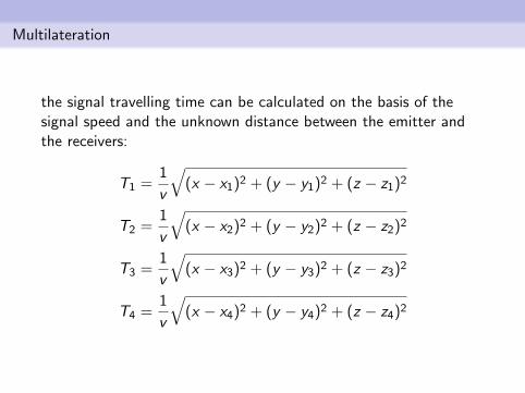
Multilateration
the signal travelling time can be calculated on the basis of thesignal speed and the unknown distance between the emitter andthe receivers:
T1 =1
v
√(x − x1)2 + (y − y1)2 + (z − z1)2
T2 =1
v
√(x − x2)2 + (y − y2)2 + (z − z2)2
T3 =1
v
√(x − x3)2 + (y − y3)2 + (z − z3)2
T4 =1
v
√(x − x4)2 + (y − y4)2 + (z − z4)2
Multilateration
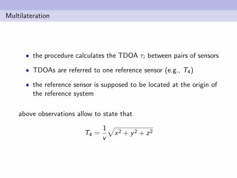
• the procedure calculates the TDOA τi between pairs of sensors
• TDOAs are referred to one reference sensor (e.g., T4)
• the reference sensor is supposed to be located at the origin ofthe reference system
above observations allow to state that
T4 =1
v
√x2 + y2 + z2
Multilateration
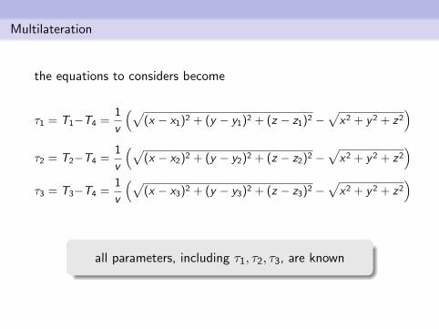
the equations to considers become
τ1 = T1−T4 =1
v
(√(x − x1)2 + (y − y1)2 + (z − z1)2 −
√x2 + y2 + z2
)τ2 = T2−T4 =
1
v
(√(x − x2)2 + (y − y2)2 + (z − z2)2 −
√x2 + y2 + z2
)τ3 = T3−T4 =
1
v
(√(x − x3)2 + (y − y3)2 + (z − z3)2 −
√x2 + y2 + z2
)
all parameters, including τ1, τ2, τ3, are known
Multilateration
• the solution of the system of equations allows to obtain theposition of the emitter
• the solution is pretty complex
• however, it can be be solved in closed form
• therefore, the exact solution can be obtained
Multilateration: accuracy
several factors affect the accuracy of the localization based onmultilateration:
• the relative positions of receivers
• the accuracy of the time-stamping of received signal
• the accuracy of time synchronization between receivers
• the bandwidth of the signal
• the accuracy of localization of receivers