robotics operatingmanual robotstudio ·...
TRANSCRIPT

ROBOTICS
Operating manualRobotStudio

Trace back information:Workspace R18-2 version a11Checked in 2018-10-11Skribenta version 5.3.008

Operating manualRobotStudio
6.08
Document ID: 3HAC032104-001Revision: X
© Copyright 2008-2018 ABB. All rights reserved.Specifications subject to change without notice.

The information in this manual is subject to change without notice and should notbe construed as a commitment by ABB. ABB assumes no responsibility for any errorsthat may appear in this manual.Except as may be expressly stated anywhere in this manual, nothing herein shall beconstrued as any kind of guarantee or warranty by ABB for losses, damages topersons or property, fitness for a specific purpose or the like.In no event shall ABB be liable for incidental or consequential damages arising fromuse of this manual and products described herein.This manual and parts thereof must not be reproduced or copied without ABB'swritten permission.Keep for future reference.Additional copies of this manual may be obtained from ABB.
Original instructions.
© Copyright 2008-2018 ABB. All rights reserved.Specifications subject to change without notice.
ABB AB, RoboticsRobotics and MotionSe-721 68 Västerås
Sweden
Table of contents13Overview of this manual ...................................................................................................................21Product documentation ....................................................................................................................23Safety ................................................................................................................................................24Network security ...............................................................................................................................
251 Introduction to RobotStudio251.1 What is RobotStudio ..........................................................................................261.2 Terms and concepts ..........................................................................................261.2.1 Hardware concepts ..................................................................................281.2.2 RobotWare concepts ...............................................................................301.2.3 RAPID concepts ......................................................................................311.2.4 Concepts of programming .........................................................................321.2.5 Targets and paths ...................................................................................331.2.6 Coordinate systems .................................................................................391.2.7 Robot axis configurations .........................................................................411.2.8 Libraries, geometries and CAD files ............................................................441.3 Installing and licensing RobotStudio .....................................................................441.3.1 Installation options and prerequisites ..........................................................451.3.2 Activating RobotStudio .............................................................................521.4 User interface ...................................................................................................521.4.1 Ribbon, tabs and groups ...........................................................................531.4.2 Layout browser .......................................................................................541.4.3 The Paths & Targets browser ....................................................................551.4.4 The Controller browser .............................................................................571.4.5 Files browser ..........................................................................................581.4.6 Add-Ins browser .....................................................................................591.4.7 Windows layout ......................................................................................601.4.8 The Output window ..................................................................................611.4.9 The Controller Status window ....................................................................631.4.10 The Operator Window ..............................................................................651.4.11 The Documents window ...........................................................................721.4.12 Using a mouse ........................................................................................731.4.13 3D Mouse ..............................................................................................741.4.14 Selecting an item ....................................................................................751.4.15 Attaching and detaching objects ................................................................761.4.16 Keyboard shortcuts .................................................................................
812 Building stations812.1 Workflow of building a station ..............................................................................832.2 Setting the Conveyor tracking station ....................................................................832.2.1 Setting Conveyor tracking .........................................................................852.3 Creating a system with external axes automatically .................................................882.4 Manually setting up system based on RobotWare 5.xx with track motion .....................882.4.1 Track motion of type RTT or IRBTx003 ........................................................892.4.2 Track motion of type IRBTx004 ..................................................................902.5 Virtual controller ...............................................................................................902.5.1 Starting a VC ..........................................................................................912.5.2 Restarting a VC .......................................................................................922.6 Station components ...........................................................................................922.6.1 Importing a station component ..................................................................942.6.2 Troubleshooting and optimizing geometries .................................................962.7 Modeling .........................................................................................................962.7.1 Objects .................................................................................................982.7.2 Mechanisms ...........................................................................................992.7.3 Tools and tooldata ...................................................................................
1002.7.4 Setting the local origin of an object .............................................................
Operating manual - RobotStudio 53HAC032104-001 Revision: X
© Copyright 2008-2018 ABB. All rights reserved.
Table of contents
1012.8 Placement .......................................................................................................1012.8.1 Placing objects .......................................................................................1022.8.2 Placing external axes ...............................................................................1042.8.3 Placing robots ........................................................................................
1073 Programming robots1073.1 Workflow for programming a robot .......................................................................1083.2 Workobjects .....................................................................................................1093.3 Jogging mechanisms .........................................................................................1103.4 Targets ............................................................................................................1123.5 Paths ..............................................................................................................1163.6 Orientations .....................................................................................................1203.7 RAPID Instructions ............................................................................................1273.8 Testing positions and motions .............................................................................1293.9 Programming MultiMove systems .........................................................................1293.9.1 About programming MultiMove ..................................................................1313.9.2 Setting up the MultiMove ..........................................................................1323.9.3 Testing the MultiMove ..............................................................................1333.9.4 Tuning the motion behavior .......................................................................1353.9.5 Creating paths ........................................................................................1363.10 Programming external axes .................................................................................1383.11 Loading and saving programs and modules ...........................................................1393.12 Synchronization ................................................................................................
1414 Deploying and distributing1414.1 Copying programs .............................................................................................1424.2 Pack & Go / Unpack & Work ................................................................................1434.3 Screen Capture .................................................................................................
1455 Simulating programs1455.1 Simulation Overview ..........................................................................................1475.2 Detecting collisions ...........................................................................................1505.3 Creating an event ..............................................................................................1515.4 Simulating I/O signals ........................................................................................1525.5 Measuring simulation time ..................................................................................
1536 Working online1536.1 Connecting a PC to the controller .........................................................................1576.2 Network settings ...............................................................................................1606.3 User Authorization .............................................................................................1626.4 The System Builder ...........................................................................................1626.4.1 About System Builder ..............................................................................1646.4.2 Viewing system properties ........................................................................1656.4.3 Building a new system .............................................................................1696.4.4 Modifying a system ..................................................................................1736.4.5 Copying a system ....................................................................................1746.4.6 Creating a system from backup ..................................................................1756.4.7 Downloading a system to a controller ..........................................................1766.4.8 Creating boot media ................................................................................1776.4.9 Examples using the System Builder when offline ...........................................1776.4.9.1 A system with support for one robot and one positioner external axis ....1806.4.9.2 Options settings for systems with positioners ...................................1816.5 The Installation Manager ....................................................................................1816.5.1 About Installation Manager .......................................................................1826.5.2 Startup and settings .................................................................................1836.5.3 Building a new system .............................................................................1856.5.4 Modifying a system ..................................................................................1876.5.5 Copying a system ....................................................................................
6 Operating manual - RobotStudio3HAC032104-001 Revision: X
© Copyright 2008-2018 ABB. All rights reserved.
Table of contents

1896.5.6 Creating a system from backup ..................................................................1916.5.7 Renaming a system .................................................................................1926.5.8 A MultiMove system with two coordinated robots ..........................................1926.5.8.1 Creating a coordinated system using System Builder .........................1946.5.8.2 Creating a coordinated system using Installation Manager ..................1956.5.9 The recovery disk function ........................................................................1976.6 Handle I/O .......................................................................................................1986.7 Configure systems ............................................................................................2046.8 Handle events ..................................................................................................
2097 File tab2097.1 Overview .........................................................................................................2117.2 New tab ...........................................................................................................2137.3 Share ..............................................................................................................2137.3.1 Pack and Go ..........................................................................................2147.3.2 Unpack and Work ....................................................................................2157.3.3 Station Viewer ........................................................................................2177.3.4 RobotStudio Meeting ...............................................................................2187.4 Options ...........................................................................................................
2278 Home tab2278.1 Overview .........................................................................................................2288.2 ABB Library .....................................................................................................2298.3 Import Library ...................................................................................................2308.4 Robot System ...................................................................................................2308.4.1 Robot System .........................................................................................2338.4.2 External Axis Wizard ................................................................................2368.5 Import Geometry ...............................................................................................2378.6 Export Geometry ...............................................................................................2388.7 Frame .............................................................................................................2388.7.1 Frame ...................................................................................................2398.7.2 Frame from Three Points ..........................................................................2418.8 Workobject ......................................................................................................2428.9 Tooldata ..........................................................................................................2438.10 Target .............................................................................................................2438.10.1 Teach Target ..........................................................................................2448.10.2 Create Target .........................................................................................2468.10.3 Create Jointtarget ....................................................................................2478.10.4 Create Targets on Edge ............................................................................2498.11 Empty Path ......................................................................................................2508.12 AutoPath .........................................................................................................2528.13 MultiMove ........................................................................................................2608.14 Teach Instruction ..............................................................................................2618.15 Move Instruction ...............................................................................................2628.16 Action Instruction ..............................................................................................2638.17 Instruction Template Manager .............................................................................2648.18 Settings ...........................................................................................................2648.18.1 Task .....................................................................................................2658.18.2 Workobject ............................................................................................2668.18.3 Tool ......................................................................................................2678.19 The Freehand Group ..........................................................................................2688.19.1 Rotate ...................................................................................................2698.19.2 Jog Joint ...............................................................................................2708.19.3 Jog Linear ..............................................................................................2718.19.4 Jog Reorient ..........................................................................................2728.19.5 MultiRobot Jog .......................................................................................2738.20 Graphics Tools .................................................................................................2748.20.1 View Tab ...............................................................................................2838.20.2 Edit Tab .................................................................................................
Operating manual - RobotStudio 73HAC032104-001 Revision: X
© Copyright 2008-2018 ABB. All rights reserved.
Table of contents
2859 Modeling tab2859.1 Overview .........................................................................................................2869.2 Component Group .............................................................................................2879.3 Empty Part .......................................................................................................2889.4 Smart Component .............................................................................................2889.4.1 Smart Component ...................................................................................2899.4.2 Smart Component Editor ..........................................................................2909.4.3 The Compose tab ....................................................................................2939.4.4 The Properties and Bindings tab ................................................................2969.4.5 The Signals and Connections tab ...............................................................2999.4.6 The Design tab .......................................................................................3009.4.7 Basic Smart Components .........................................................................3189.4.8 Property Editor .......................................................................................3199.4.9 The Simulation Watch window ...................................................................3219.5 Tags ...............................................................................................................3229.6 Selection of Objects ...........................................................................................3239.7 Solid ...............................................................................................................3279.8 Surface ...........................................................................................................3299.9 Curve ..............................................................................................................3359.10 Border .............................................................................................................3379.11 Intersect ..........................................................................................................3389.12 Subtract ..........................................................................................................3399.13 Union ..............................................................................................................3409.14 Extrude Surface or Curve ....................................................................................3429.15 Line from Normal ..............................................................................................3439.16 The Measure Group ...........................................................................................3449.17 Create Mechanism ............................................................................................3519.18 Create Tool ......................................................................................................3539.19 Physics Tools ...................................................................................................
35510 Simulation tab35510.1 Overview .........................................................................................................35610.2 Create Collision Set ...........................................................................................35710.3 Simulation Setup ...............................................................................................35910.4 Event Manager .................................................................................................36510.5 Station Logic ....................................................................................................36610.6 Activate Mechanical Units ...................................................................................36710.7 Simulation Control .............................................................................................36810.8 I/O Simulator ....................................................................................................37010.9 TCP Trace .......................................................................................................37110.10 Stopwatch ........................................................................................................37210.11 Signal Analyzer .................................................................................................37210.11.1 Signal Analyzer for both real and virtual controllers .......................................37310.11.2 Signal Setup ...........................................................................................37610.11.3 Layout and usage ....................................................................................37910.11.4 History ..................................................................................................38010.12 Record Movie ...................................................................................................38110.13 Conveyor Tracking Mechanism ............................................................................38110.13.1 Conveyor Tracking ..................................................................................38210.13.2 Conveyor Simulation ................................................................................
38511 Controller tab38511.1 Real and virtual controllers .................................................................................38611.2 Features for both virtual and real controllers ..........................................................38611.2.1 Add Controller ........................................................................................38911.2.2 Events ...................................................................................................39011.2.3 Inputs/Outputs ........................................................................................39211.2.4 ScreenMaker ..........................................................................................
8 Operating manual - RobotStudio3HAC032104-001 Revision: X
© Copyright 2008-2018 ABB. All rights reserved.
Table of contents

39411.2.5 Restart a controller ..................................................................................39611.2.6 Back up a system ....................................................................................39811.2.7 Restore a system ....................................................................................40011.2.8 System Builder .......................................................................................40111.2.9 Installation Manager ................................................................................40211.2.10 Configuration editor .................................................................................40411.2.11 Load Parameters .....................................................................................40511.2.12 Save Parameters .....................................................................................40611.2.13 Transfer ................................................................................................40911.2.14 Signal Analyzer Online .............................................................................41111.2.15 Safety Configuration ................................................................................41211.2.16 Collision Avoidance .................................................................................41611.3 Features for real controllers ................................................................................41611.3.1 Request Write Access ..............................................................................41711.3.2 Release Write Access ..............................................................................41811.3.3 Authenticate ...........................................................................................41911.3.4 File transfer ............................................................................................42111.3.5 FlexPendant Viewer .................................................................................42211.3.6 Import Options ........................................................................................42311.3.7 Properties ..............................................................................................42611.3.8 Go Offline ..............................................................................................42711.3.9 Online Monitor ........................................................................................42911.3.10 Visual SafeMove .....................................................................................43011.3.11 User Accounts ........................................................................................43511.3.12 UAS Grant Viewer ...................................................................................43911.3.13 Integrated Vision .....................................................................................44011.3.14 Jobs .....................................................................................................44511.4 Features for virtual controllers .............................................................................44511.4.1 Virtual FlexPendant .................................................................................44611.4.2 Control Panel .........................................................................................44711.4.3 Shutdown ..............................................................................................44811.4.4 Set Task Frames .....................................................................................44911.4.5 Edit System ............................................................................................
45112 RAPID tab45112.1 Overview of the RAPID tab ..................................................................................45212.2 Synchronize to Station .......................................................................................45312.3 Synchronize to RAPID ........................................................................................45412.4 Edit RAPID code ...............................................................................................45912.5 Find and replace RAPID code ..............................................................................46112.6 Manage RAPID modules .....................................................................................46312.7 Edit RAPID data ................................................................................................46412.8 Editing RAPID code using Path Editor ...................................................................46512.9 Manage RAPID files and backups .........................................................................46612.10 Manage RAPID code on the controller ...................................................................46612.10.1 Manage RAPID programs .........................................................................46812.10.2 RAPID Tasks ..........................................................................................47112.10.3 Run Mode ..............................................................................................47212.10.4 Adjust Robtargets ...................................................................................47512.11 Test and debug .................................................................................................47512.11.1 Commands for testing and debugging .........................................................47612.11.2 Using the Program Pointer ........................................................................47812.11.3 Using the RAPID Profiler ..........................................................................48012.12 RAPID Breakpoints window .................................................................................48112.13 RAPID Call Stack window ...................................................................................48212.14 RAPID Watch window ........................................................................................48312.15 Examples of using the RAPID editor .....................................................................
Operating manual - RobotStudio 93HAC032104-001 Revision: X
© Copyright 2008-2018 ABB. All rights reserved.
Table of contents
48513 Add-Ins tab48613.1 RobotApps .......................................................................................................48713.1.1 Distribution package ................................................................................48913.2 Migration tools ..................................................................................................49013.3 Gearbox Heat Prediction .....................................................................................
49314 Context menus49314.1 Add to Path ......................................................................................................49414.2 Align Frame Orientation ......................................................................................49514.3 Align Target Orientation .....................................................................................49614.4 Attach to ..........................................................................................................49714.5 Configurations ..................................................................................................49814.6 Configurations ..................................................................................................49914.7 Convert Frame to Workobject ..............................................................................50014.8 Work envelope ..................................................................................................50114.9 Convert to Move Circular ....................................................................................50214.10 Copy / Apply Orientation .....................................................................................50314.11 Detach ............................................................................................................50414.12 Defeature .........................................................................................................50514.13 Execute Move Instruction ...................................................................................50614.14 External Axis Interpolation ..................................................................................50714.15 Graphic Appearance ..........................................................................................50914.16 Remove internal geometry ..................................................................................51014.17 Go to Visualization and Go to Declaration ..............................................................51114.18 Zone visualization .............................................................................................51214.19 Zone reduction .................................................................................................51314.20 Interpolate Path ................................................................................................51414.21 Invert ..............................................................................................................51514.22 Jump to Target .................................................................................................51614.23 Linked Geometry ...............................................................................................51714.24 Modify Library Component ..................................................................................51814.25 Mechanism Joint Jog .........................................................................................52014.26 Mechanism Linear Jog .......................................................................................52114.27 Mirror Path .......................................................................................................52214.28 Mirror ..............................................................................................................52314.29 Modify Curve ....................................................................................................52514.30 Modify External Axis ..........................................................................................52614.31 Modify Instruction ..............................................................................................52714.32 Modify Mechanism ............................................................................................52814.33 Modify Tooldata ................................................................................................52914.34 Modify Workobject .............................................................................................53014.35 Move Along Path ...............................................................................................53114.36 Move to Pose ...................................................................................................53214.37 Offset Position ..................................................................................................53314.38 Place ..............................................................................................................53514.39 Protected Smart Component ...............................................................................53614.40 Remove Unused Targets ....................................................................................53714.41 Rename Targets ...............................................................................................53814.42 Reverse Path ....................................................................................................53914.43 Rotate .............................................................................................................54014.44 Rotate Path ......................................................................................................54114.45 Set Local Origin ................................................................................................54214.46 Set Normal to Surface ........................................................................................54314.47 Set Position .....................................................................................................54414.48 Tool Compensation ...........................................................................................54514.49 Translate Path ..................................................................................................54614.50 View Robot at Target .........................................................................................54714.51 View Tool at Target ............................................................................................
10 Operating manual - RobotStudio3HAC032104-001 Revision: X
© Copyright 2008-2018 ABB. All rights reserved.
Table of contents
54915 ScreenMaker tab54915.1 Introduction to ScreenMaker ...............................................................................55215.2 Development environment ..................................................................................55715.3 Working with ScreenMaker .................................................................................55715.3.1 Managing projects ...................................................................................57615.3.2 Application variables ................................................................................57715.3.3 Data binding ...........................................................................................58015.3.4 ScreenMaker Doctor ................................................................................58315.4 Frequently asked questions ................................................................................58615.5 Tutorial ............................................................................................................58615.5.1 Overview ...............................................................................................58715.5.2 Designing the FlexArc operator panel .........................................................59015.5.3 Designing the screen ...............................................................................59615.5.4 Building and deploying the project ..............................................................
597A Technical support
599Index
Operating manual - RobotStudio 113HAC032104-001 Revision: X
© Copyright 2008-2018 ABB. All rights reserved.
Table of contents

This page is intentionally left blank

Overview of this manualAbout this manual
RobotStudio is a PC application for modeling, offline programming, and simulationof robot cells. This manual describes how to create, program and simulate robotcells and stations using RobotStudio. This manual also explains the terms andconcepts related to both offline and online programming.
UsageThis manual should be used when working with the offline or online functions ofRobotStudio.
Who should read this manual?This manual is intended for RobotStudio users, proposal engineers, mechanicaldesigners, offline programmers, robot technicians, service technicians, PLCprogrammers, Robot programmers, and Robot System integrators.
PrerequisitesThe reader should have basic knowledge of:
• Robot programming• Generic Windows handling• 3D CAD programs
Organization of chaptersThe operating manual is structured in the following chapters:
ContentsChapter
Contains installation instructions, basic explana-tions of the terms and concepts related to roboticsand programming, and a description of the GUI.
Introduction toRobot-Studio on page 25
1
Describes how to build stations in RobotStudio.This includes importing and configuring the equip-ment to be simulated, as well as testing the reach-ability for finding the optimal station layout.
Building stations onpage 81
2
Describes how to create robot movements, I/Osignals, process instructions and logics in a RAPIDprogram for the robots. It also describes how to runand test the program.
Programming robotson page 107
3
Describes how to simulate and validate robot pro-grams.
Simulating programson page 145
4
Describes how to transfer systems between Robot-Studio’s virtual controllers and real IRC5 control-lers, how to copy programs, how to package anactive station for moving between RobotStudioPCs, and how to capture a screen.
Deploying and distrib-uting on page 141
5
Covers the functionality of the Minimal Installation,describing such online functions as building sys-tems (with offline examples), handling I/O andevents, and configuring systems.
Working online onpage 153
6
Continues on next pageOperating manual - RobotStudio 133HAC032104-001 Revision: X
© Copyright 2008-2018 ABB. All rights reserved.
Overview of this manual
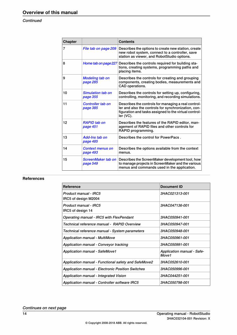
ContentsChapter
Describes the options to create new station, createnew robot system, connect to a controller, savestation as viewer, and RobotStudio options.
File tab on page 2097
Describes the controls required for building sta-tions, creating systems, programming paths andplacing items.
Home tabonpage2278
Describes the controls for creating and groupingcomponents, creating bodies, measurements andCAD operations.
Modeling tab onpage 285
9
Describes the controls for setting up, configuring,controlling, monitoring, and recording simulations.
Simulation tab onpage 355
10
Describes the controls for managing a real control-ler and also the controls for synchronization, con-figuration and tasks assigned to the virtual control-ler (VC).
Controller tab onpage 385
11
Describes the features of the RAPID editor, man-agement of RAPID files and other controls forRAPID programming.
RAPID tab onpage 451
12
Describes the control for PowerPacs .Add-Ins tab onpage 485
13
Describes the options available from the contextmenus.
Context menus onpage 493
14
Describes the ScreenMaker development tool, howto manage projects in ScreenMaker and the variousmenus and commands used in the application.
ScreenMaker tab onpage 549
15
References
Document IDReference
3HAC021313-001Product manual - IRC5IRC5 of design M2004
3HAC047136-001Product manual - IRC5IRC5 of design 14
3HAC050941-001Operating manual - IRC5 with FlexPendant
3HAC050947-001Technical reference manual - RAPID Overview
3HAC050948-001Technical reference manual - System parameters
3HAC050961-001Application manual - MultiMove
3HAC050991-001Application manual - Conveyor tracking
Application manual - Safe-Move1
Application manual - SafeMove1
3HAC052610-001Application manual - Functional safety and SafeMove2
3HAC050996-001Application manual - Electronic Position Switches
3HAC044251-001Application manual - Integrated Vision
3HAC050798-001Application manual - Controller software IRC5
Continues on next page14 Operating manual - RobotStudio
3HAC032104-001 Revision: X© Copyright 2008-2018 ABB. All rights reserved.
Overview of this manualContinued

Note
The document numbers that are listed for software documents are valid forRobotWare 6. Equivalent documents are available for RobotWare 5.
Revisions
DescriptionRevision
First revision, called RobotStudio 2008, released for Partner Days. Theentire manual has been adapted to the new GUI, in which RobotStudioOn-line has been integrated.
A
Released with RobotStudio 5.12.BThe following updates were made in the manual:
• Conveyor Tracking on page 381• Create Conveyor on page 344• Conveyor Simulation on page 382• Two robot systems sharing the same task frame position• Two robot systems having different task frame positions.• Creating a system with external axes automatically on page 85• Track motion of type RTT or IRBTx003 on page 88• Track motion of type IRBTx004 on page 89• The Operator Window on page 63• Station Viewer on page 215• Recording the simulation on page 380• Viewpoint• Linked Geometry on page 516
Released with RobotStudio 5.13.C• Merged chapters The Offline tab and The Online tab• Added the missing information from RobotStudio Online manual.• Integrated ScreenMaker. See ScreenMaker on page 392.
Added the following new content:• Smart Component on page 288• The Simulation Watch window on page 319• The Documents window on page 65• Station Logic on page 365• Simulation Setup on page 357
Updated the changes related to handling Task Frames.• Updated Modifying Task frame on page 448.• Added Placing robots on page 104.• Updated Creating a system from layout on page 230.
Released with RobotStudio 5.13.02.DThe ScreenMaker tutorial was updated. See Tutorial on page 586 .
Released with RobotStudio 5.14.E• Added The Controller Status window on page 61.• Updated the sectionsSimulation Setup on page357 andSimulation
Control on page 367.• MovedRAPIDWatch window on page482 to the chapterCommon
features in Online and Offline tabs.• Updated The Documents window on page 65 (added Station
mode).
Continues on next pageOperating manual - RobotStudio 153HAC032104-001 Revision: X
© Copyright 2008-2018 ABB. All rights reserved.
Overview of this manualContinued
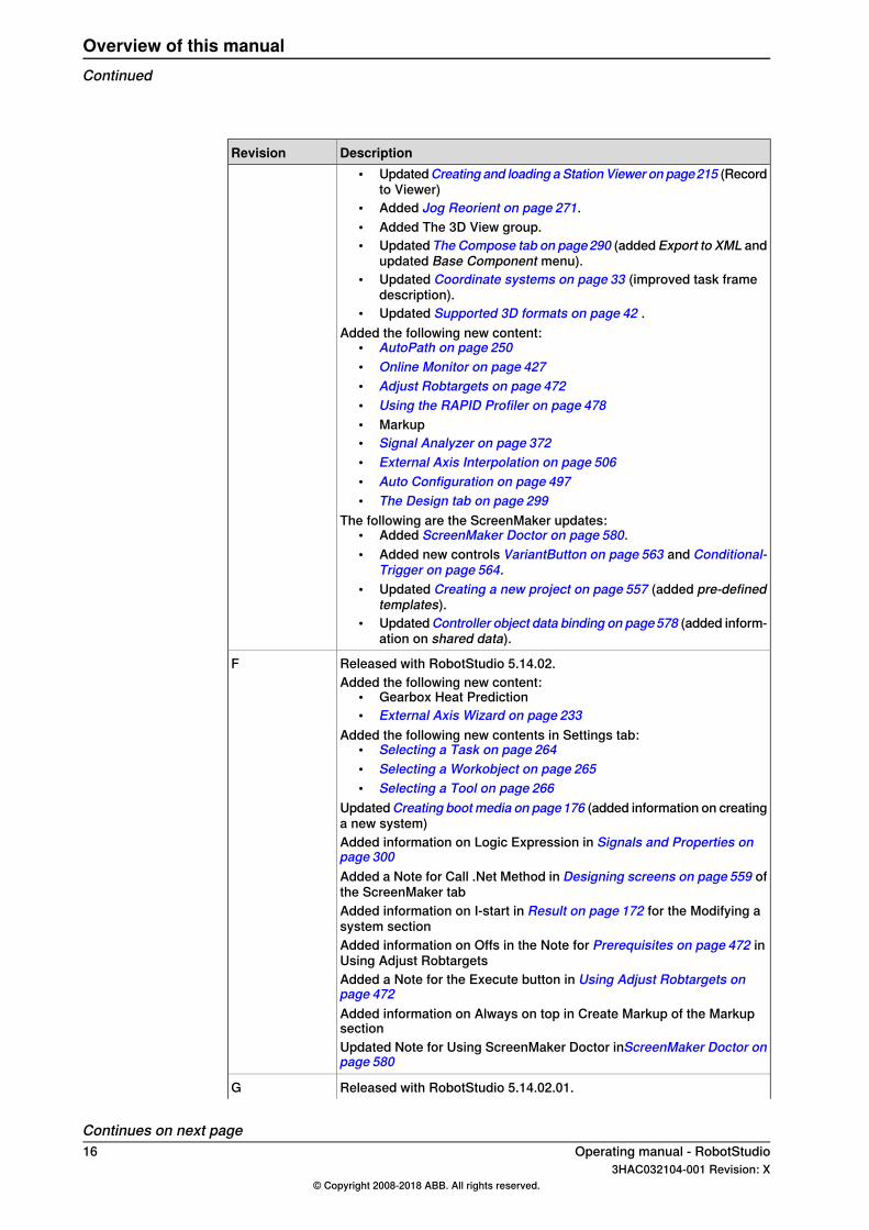
DescriptionRevision• UpdatedCreating and loading aStationViewer on page215 (Record
to Viewer)• Added Jog Reorient on page 271.• Added The 3D View group.• Updated The Compose tab on page290 (added Export to XML and
updated Base Component menu).• Updated Coordinate systems on page 33 (improved task frame
description).• Updated Supported 3D formats on page 42 .
Added the following new content:• AutoPath on page 250• Online Monitor on page 427• Adjust Robtargets on page 472• Using the RAPID Profiler on page 478• Markup• Signal Analyzer on page 372• External Axis Interpolation on page 506• Auto Configuration on page 497• The Design tab on page 299
The following are the ScreenMaker updates:• Added ScreenMaker Doctor on page 580.• Added new controls VariantButton on page 563 and Conditional-
Trigger on page 564.• Updated Creating a new project on page 557 (added pre-defined
templates).• UpdatedController object data binding on page578 (added inform-
ation on shared data).
Released with RobotStudio 5.14.02.FAdded the following new content:
• Gearbox Heat Prediction• External Axis Wizard on page 233
Added the following new contents in Settings tab:• Selecting a Task on page 264• Selecting a Workobject on page 265• Selecting a Tool on page 266
UpdatedCreating bootmedia on page176 (added information on creatinga new system)Added information on Logic Expression in Signals and Properties onpage 300Added a Note for Call .Net Method in Designing screens on page 559 ofthe ScreenMaker tabAdded information on I-start in Result on page 172 for the Modifying asystem sectionAdded information on Offs in the Note for Prerequisites on page 472 inUsing Adjust RobtargetsAdded a Note for the Execute button in Using Adjust Robtargets onpage 472Added information on Always on top in Create Markup of the MarkupsectionUpdated Note for Using ScreenMaker Doctor inScreenMaker Doctor onpage 580
Released with RobotStudio 5.14.02.01.G
Continues on next page16 Operating manual - RobotStudio
3HAC032104-001 Revision: X© Copyright 2008-2018 ABB. All rights reserved.
Overview of this manualContinued
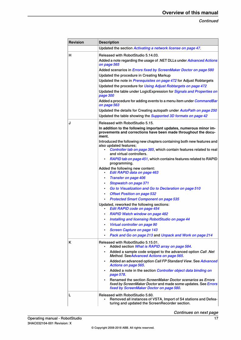
DescriptionRevisionUpdated the section Activating a network license on page 47.
Released with RobotStudio 5.14.03.HAdded a note regarding the usage of .NET DLLs underAdvanced Actionson page 565Added scenarios in Errors fixed by ScreenMaker Doctor on page 580Updated the procedure in Creating MarkupUpdated the note in Prerequisites on page 472 for Adjust RobtargetsUpdated the procedure for Using Adjust Robtargets on page 472Updated the table under LogicExpression for Signals and Properties onpage 300Added a procedure for adding events to a menu item underCommandBaron page 563Updated the details for Creating autopath under AutoPath on page 250Updated the table showing the Supported 3D formats on page 42
Released with RobotStudio 5.15.JIn addition to the following important updates, numerous minor im-provements and corrections have been made throughout the docu-ment.Introduced the following new chapters containing both new features andalso updated features;
• Controller tab on page 385, which contain features related to realand virtual controllers.
• RAPID tab on page451, which contains features related to RAPIDprogramming.
Added the following new content:• Edit RAPID data on page 463• Transfer on page 406• Stopwatch on page 371• Go to Visualization and Go to Declaration on page 510• Offset Position on page 532• Protected Smart Component on page 535
Updated, reworked the following sections:• Edit RAPID code on page 454• RAPID Watch window on page 482• Installing and licensing RobotStudio on page 44• Virtual controller on page 90• Screen Capture on page 143• Pack and Go on page 213 and Unpack and Work on page 214
Released with RobotStudio 5.15.01.K• Added section What is RAPID array on page 584.• Added a sample code snippet to the advanced option Call .Net
Method. SeeAdvanced Actions on page 565.• Added an advanced optionCall FP Standard View. SeeAdvanced
Actions on page 565.• Added a note in the section Controller object data binding on
page 578.• Renamed the section ScreenMaker Doctor scenarios as Errors
fixed by ScreenMaker Doctor and made some updates. See Errorsfixed by ScreenMaker Doctor on page 580.
Released with RobotStudio 5.60.L• Removed all instances of VSTA, Import of S4 stations and Defea-
turing and updated the ScreenRecorder section.
Continues on next pageOperating manual - RobotStudio 173HAC032104-001 Revision: X
© Copyright 2008-2018 ABB. All rights reserved.
Overview of this manualContinued
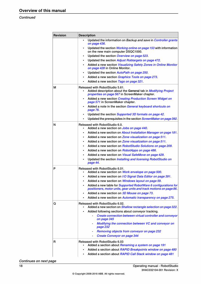
DescriptionRevision• Updated the information on Backup and save in Controller grants
on page 436.• Updated the section Working online on page153 with information
on the new main computer DSQC1000.• Updated the section Overview on page 523.• Updated the section Adjust Robtargets on page 472.• Added a new section Visualizing Safety Zones in Online Monitor
on page 428 in Online Monitor.• Updated the section AutoPath on page 250.• Added a new section Graphics Tools on page 273.• Added a new section Tags on page 321.
Released with RobotStudio 5.61.M• Added description about the General tab in Modifying Project
properties on page 567 in ScreenMaker chapter.• Added a new section Creating Production Screen Widget on
page 571 in ScreenMaker chapter.• Added a note in the section General keyboard shortcuts on
page 76.• Updated the section Supported 3D formats on page 42.• Updated the prerequisites in the sectionScreenMaker on page392.
Released with RobotStudio 6.0.N• Added a new section on Jobs on page 440.• Added a new section on About Installation Manager on page181.• Added a new section on Zone visualization on page 511.• Added a new section on Zone visualization on page 511.• Added a new section on RobotStudio Solutions on page 209.• Added a new section on RobotApps on page 486.• Added a new section on Visual SafeMove on page 429.• Updated the section Installing and licensing RobotStudio on
page 44.
Released with RobotStudio 6.01.P• Added a new section on Work envelope on page 500.• Added a new section on I/O Signal Data Editor on page 391.• Added a new section on Windows layout on page 59.• Added a new table for Supported RobotWare 6 configurations for
positioners, motor units, gear units and track motions on page86.• Added a new section on 3D Mouse on page 73.• Added a new section on Automatic transparency on page 275.
Released with RobotStudio 6.02.Q• Added a new section on Shallow rectangle selection on page322.• Added following sections about conveyor tracking.
- Create connection between virtual controller and conveyoron page 345
- Modifying the connection between VC and conveyor onpage 232
- Removing objects from conveyor on page 232- Create Conveyor on page 344
Released with RobotStudio 6.03R• Added a section about Renaming a system on page 191• Added a section about RAPID Breakpoints window on page 480• Added a section about RAPID Call Stack window on page 481
Continues on next page18 Operating manual - RobotStudio
3HAC032104-001 Revision: X© Copyright 2008-2018 ABB. All rights reserved.
Overview of this manualContinued
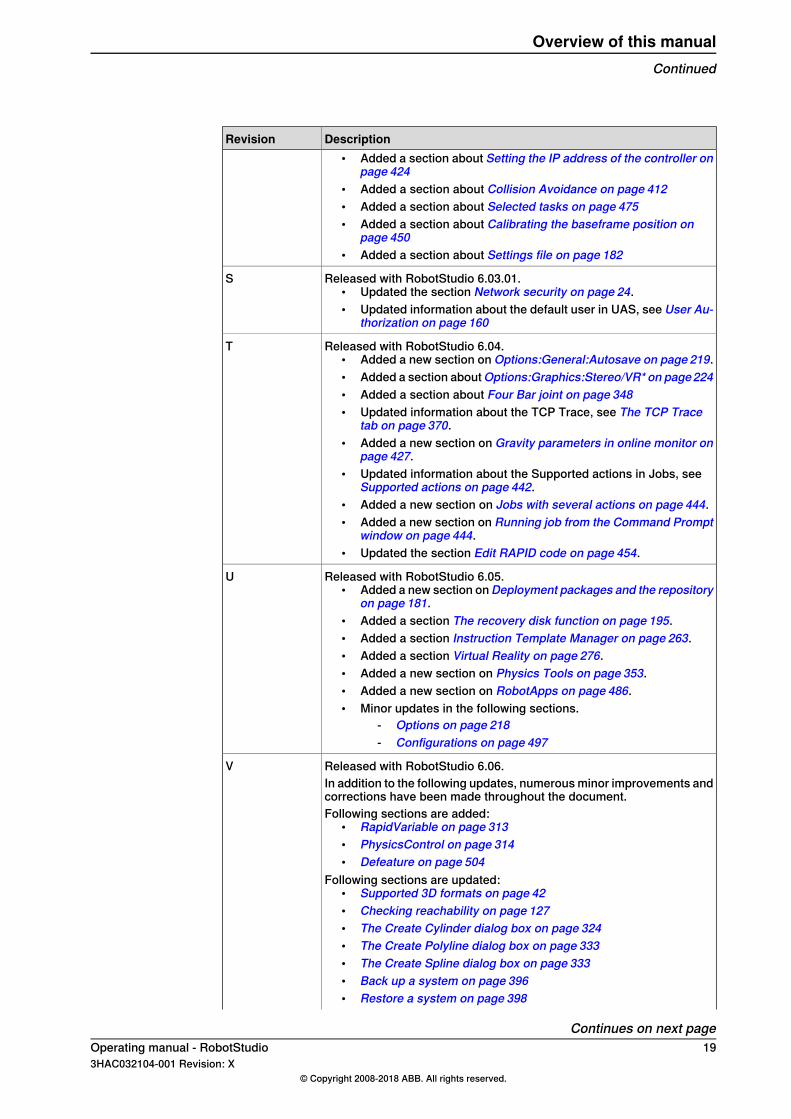
DescriptionRevision• Added a section about Setting the IP address of the controller on
page 424• Added a section about Collision Avoidance on page 412• Added a section about Selected tasks on page 475• Added a section about Calibrating the baseframe position on
page 450• Added a section about Settings file on page 182
Released with RobotStudio 6.03.01.S• Updated the section Network security on page 24.• Updated information about the default user in UAS, see User Au-
thorization on page 160
Released with RobotStudio 6.04.T• Added a new section on Options:General:Autosave on page 219.• Added a section aboutOptions:Graphics:Stereo/VR* on page224• Added a section about Four Bar joint on page 348• Updated information about the TCP Trace, see The TCP Trace
tab on page 370.• Added a new section on Gravity parameters in online monitor on
page 427.• Updated information about the Supported actions in Jobs, see
Supported actions on page 442.• Added a new section on Jobs with several actions on page 444.• Added a new section on Running job from the Command Prompt
window on page 444.• Updated the section Edit RAPID code on page 454.
Released with RobotStudio 6.05.U• Added a new section onDeployment packages and the repository
on page 181.• Added a section The recovery disk function on page 195.• Added a section Instruction Template Manager on page 263.• Added a section Virtual Reality on page 276.• Added a new section on Physics Tools on page 353.• Added a new section on RobotApps on page 486.• Minor updates in the following sections.
- Options on page 218- Configurations on page 497
Released with RobotStudio 6.06.VIn addition to the following updates, numerous minor improvements andcorrections have been made throughout the document.Following sections are added:
• RapidVariable on page 313• PhysicsControl on page 314• Defeature on page 504
Following sections are updated:• Supported 3D formats on page 42• Checking reachability on page 127• The Create Cylinder dialog box on page 324• The Create Polyline dialog box on page 333• The Create Spline dialog box on page 333• Back up a system on page 396• Restore a system on page 398
Continues on next pageOperating manual - RobotStudio 193HAC032104-001 Revision: X
© Copyright 2008-2018 ABB. All rights reserved.
Overview of this manualContinued
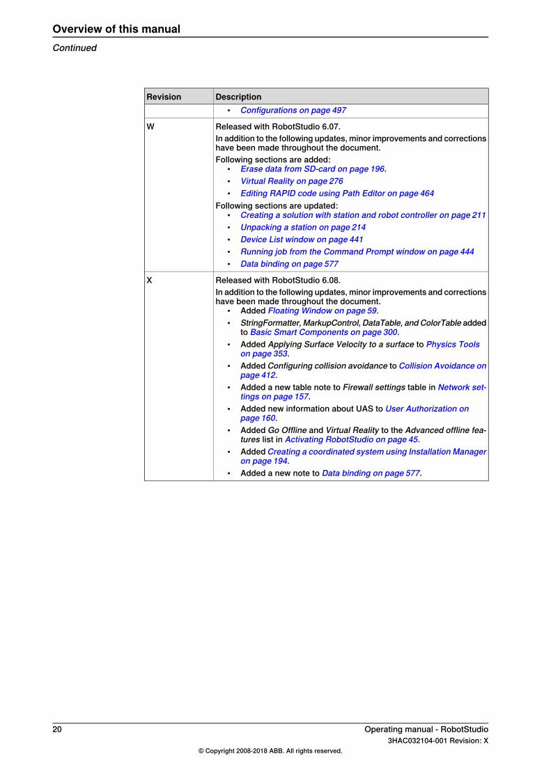
DescriptionRevision• Configurations on page 497
Released with RobotStudio 6.07.WIn addition to the following updates, minor improvements and correctionshave been made throughout the document.Following sections are added:
• Erase data from SD-card on page 196.• Virtual Reality on page 276• Editing RAPID code using Path Editor on page 464
Following sections are updated:• Creating a solution with station and robot controller on page 211• Unpacking a station on page 214• Device List window on page 441• Running job from the Command Prompt window on page 444• Data binding on page 577
Released with RobotStudio 6.08.XIn addition to the following updates, minor improvements and correctionshave been made throughout the document.
• Added Floating Window on page 59.• StringFormatter, MarkupControl, DataTable, andColorTable added
to Basic Smart Components on page 300.• Added Applying Surface Velocity to a surface to Physics Tools
on page 353.• Added Configuring collision avoidance to Collision Avoidance on
page 412.• Added a new table note to Firewall settings table in Network set-
tings on page 157.• Added new information about UAS to User Authorization on
page 160.• Added Go Offline and Virtual Reality to the Advanced offline fea-
tures list in Activating RobotStudio on page 45.• Added Creating a coordinated system using Installation Manager
on page 194.• Added a new note to Data binding on page 577.
20 Operating manual - RobotStudio3HAC032104-001 Revision: X
© Copyright 2008-2018 ABB. All rights reserved.
Overview of this manualContinued
Product documentationCategories for user documentation from ABB Robotics
The user documentation from ABB Robotics is divided into a number of categories.This listing is based on the type of information in the documents, regardless ofwhether the products are standard or optional.All documents can be found via myABB Business Portal, www.myportal.abb.com.
Product manualsManipulators, controllers, DressPack/SpotPack, and most other hardware isdelivered with a Product manual that generally contains:
• Safety information.• Installation and commissioning (descriptions of mechanical installation or
electrical connections).• Maintenance (descriptions of all required preventive maintenance procedures
including intervals and expected life time of parts).• Repair (descriptions of all recommended repair procedures including spare
parts).• Calibration.• Decommissioning.• Reference information (safety standards, unit conversions, screw joints, lists
of tools).• Spare parts list with corresponding figures (or references to separate spare
parts lists).• References to circuit diagrams.
Technical reference manualsThe technical reference manuals describe reference information for roboticsproducts, for example lubrication, the RAPID language, and system parameters.
Application manualsSpecific applications (for example software or hardware options) are described inApplication manuals. An application manual can describe one or severalapplications.An application manual generally contains information about:
• The purpose of the application (what it does and when it is useful).• What is included (for example cables, I/O boards, RAPID instructions, system
parameters, software).• How to install included or required hardware.• How to use the application.• Examples of how to use the application.
Continues on next pageOperating manual - RobotStudio 213HAC032104-001 Revision: X
© Copyright 2008-2018 ABB. All rights reserved.
Product documentation

Operating manualsThe operating manuals describe hands-on handling of the products. The manualsare aimed at those having first-hand operational contact with the product, that isproduction cell operators, programmers, and troubleshooters.
22 Operating manual - RobotStudio3HAC032104-001 Revision: X
© Copyright 2008-2018 ABB. All rights reserved.
Product documentationContinued
SafetySafety of personnel
A robot is heavy and extremely powerful regardless of its speed. A pause or longstop in movement can be followed by a fast hazardous movement. Even if a patternof movement is predicted, a change in operation can be triggered by an externalsignal resulting in an unexpected movement.Therefore, it is important that all safety regulations are followed when enteringsafeguarded space.
Safety regulationsBefore beginning work with the robot, make sure you are familiar with the safetyregulations described in the manualOperatingmanual - General safety information.
Operating manual - RobotStudio 233HAC032104-001 Revision: X
© Copyright 2008-2018 ABB. All rights reserved.
Safety
Network securityNetwork security
This product is designed to be connected to and to communicate information anddata via a network interface, It is your sole responsibility to provide and continuouslyensure a secure connection between the product and to your network or any othernetwork (as the case may be). You shall establish and maintain any appropriatemeasures (such as but not limited to the installation of firewalls, application ofauthentication measures, encryption of data, installation of anti-virus programs,etc) to protect the product, the network, its system and the interface against anykind of security breaches, unauthorized access, interference, intrusion, leakageand/or theft of data or information. ABB Ltd and its entities are not liable fordamages and/or losses related to such security breaches, any unauthorized access,interference, intrusion, leakage and/or theft of data or information.
24 Operating manual - RobotStudio3HAC032104-001 Revision: X
© Copyright 2008-2018 ABB. All rights reserved.
Network security
1 Introduction to RobotStudio1.1 What is RobotStudio
RobotStudio is a PC application for modeling, offline programming, and simulationof robot cells.RobotStudio allows you to work with an off-line controller, which is a virtual IRC5controller running locally on your PC. This offline controller is also referred to asthe virtual controller (VC). RobotStudio also allows you to work with the real physicalIRC5 controller, which is simply referred to as the real controller.When RobotStudio is used with real controllers, it is referred to as the online mode.When working without being connected to a real controller, or while being connectedto a virtual controller, RobotStudio is said to be in offline mode.RobotStudio offers the following installation options:
• Complete• Custom, allowing user-customized contents and paths• Minimal, allowing you to run RobotStudio in online mode only.
Operating manual - RobotStudio 253HAC032104-001 Revision: X
© Copyright 2008-2018 ABB. All rights reserved.
1 Introduction to RobotStudio1.1 What is RobotStudio
1.2 Terms and concepts
1.2.1 Hardware concepts
OverviewThis section introduces the hardware in a typical IRC5 robot cell. For detailedexplanations, see the manuals related to IRC5 robots specified in References onpage 14.
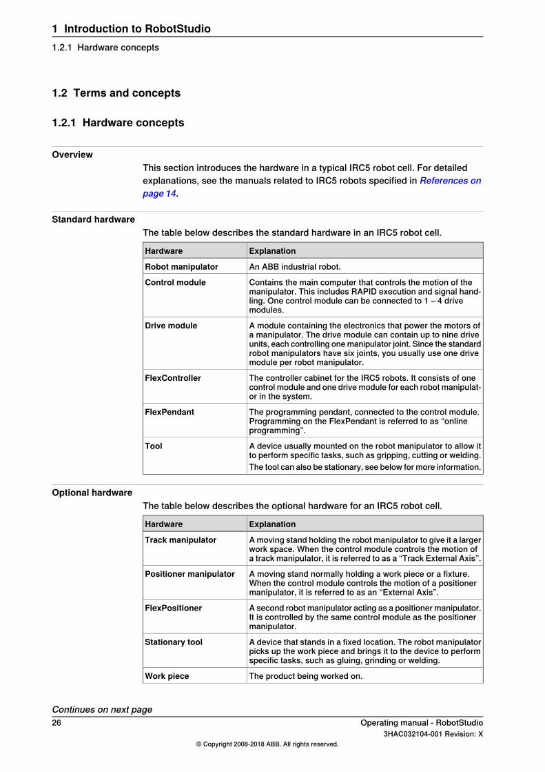
Standard hardwareThe table below describes the standard hardware in an IRC5 robot cell.
ExplanationHardware
An ABB industrial robot.Robot manipulator
Contains the main computer that controls the motion of themanipulator. This includes RAPID execution and signal hand-ling. One control module can be connected to 1 – 4 drivemodules.
Control module
A module containing the electronics that power the motors ofa manipulator. The drive module can contain up to nine driveunits, each controlling one manipulator joint. Since the standardrobot manipulators have six joints, you usually use one drivemodule per robot manipulator.
Drive module
The controller cabinet for the IRC5 robots. It consists of onecontrol module and one drive module for each robot manipulat-or in the system.
FlexController
The programming pendant, connected to the control module.Programming on the FlexPendant is referred to as “onlineprogramming”.
FlexPendant
A device usually mounted on the robot manipulator to allow itto perform specific tasks, such as gripping, cutting or welding.
Tool
The tool can also be stationary, see below for more information.
Optional hardwareThe table below describes the optional hardware for an IRC5 robot cell.
ExplanationHardware
A moving stand holding the robot manipulator to give it a largerwork space. When the control module controls the motion ofa track manipulator, it is referred to as a “Track External Axis”.
Track manipulator
A moving stand normally holding a work piece or a fixture.When the control module controls the motion of a positionermanipulator, it is referred to as an “External Axis”.
Positioner manipulator
A second robot manipulator acting as a positioner manipulator.It is controlled by the same control module as the positionermanipulator.
FlexPositioner
A device that stands in a fixed location. The robot manipulatorpicks up the work piece and brings it to the device to performspecific tasks, such as gluing, grinding or welding.
Stationary tool
The product being worked on.Work piece
Continues on next page26 Operating manual - RobotStudio
3HAC032104-001 Revision: X© Copyright 2008-2018 ABB. All rights reserved.
1 Introduction to RobotStudio1.2.1 Hardware concepts
ExplanationHardware
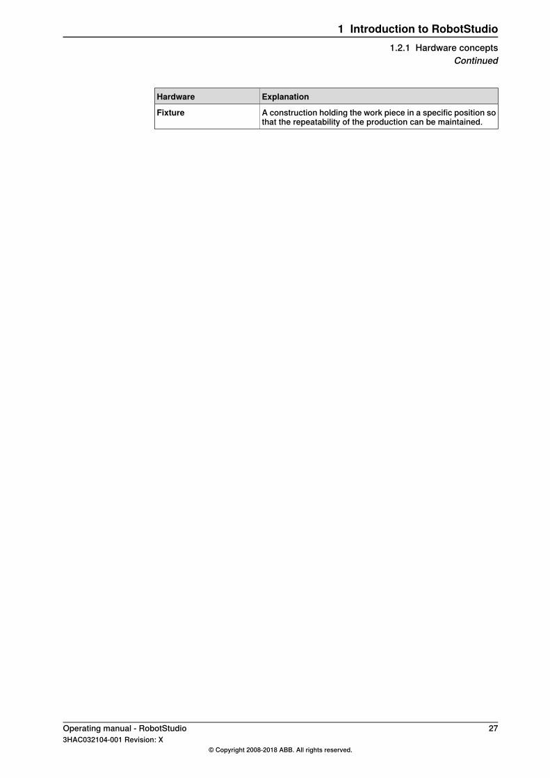
A construction holding the work piece in a specific position sothat the repeatability of the production can be maintained.
Fixture
Operating manual - RobotStudio 273HAC032104-001 Revision: X
© Copyright 2008-2018 ABB. All rights reserved.
1 Introduction to RobotStudio1.2.1 Hardware concepts
Continued

1.2.2 RobotWare concepts
OverviewThis section introduces terminology regarding RobotWare. For detailedexplanations, see the manuals related to IRC5 robots specified in References onpage 14.
RobotWareThe table below describes the RobotWare terminology and concepts that can beuseful when working with RobotStudio.
ExplanationConcept
As a concept, refers to both the software used to create a Ro-botWare System and the RobotWare systems themselves.
RobotWare
When installing RobotStudio, only one version of RobotWarewill be installed. To simulate a specific RobotWare system, theRobotWare version used for this particular RobotWare systemmust be installed on your PC.
RobotWare installation
RobotWare 5 is installed into the PC’s program files folder usinga standard PC installer. RobotWare 6 is automatically installedfor the Complete installation option of RobotStudio. Alternat-ively, use the RobotApps page in the Add-Ins tab to installRobotWare 6.
Used when you create a new RobotWare system or upgradean existing system. The RobotWare keys unlock the RobotWareoptions included in the system, and determine the RobotWareversion from which the RobotWare system will be built.
RobotWare Key
For IRC5 systems there are three types of RobotWare keys:• The controller key, which specifies the controller and
software options.• The drive keys, which specify the robots in the system.
The system has one drive key for each robot it uses.• add-ins specify additional options, like positioner extern-
al axes.A virtual key allows you to select any RobotWare options youwish, but a RobotWare system created from a virtual key canonly be used in a virtual environment such as RobotStudio.
A set of software files that, when loaded into a controller, en-ables all functions, configurations, data and programs con-trolling the robot system.
RobotWare system
RobotWare systems are created in the RobotStudio software.The systems can be stored and saved on a PC, as well as onthe control module.RobotWare systems can be edited by RobotStudio or theFlexPendant.
Each RobotWare is released with a major and a minor versionnumber, separated by a dot. The RobotWare version for IRC5is 6.xx, where xx identifies the minor version.
RobotWare version
When ABB releases a new robot model, a new RobotWareversion will be released with support for the new robot.
Continues on next page28 Operating manual - RobotStudio
3HAC032104-001 Revision: X© Copyright 2008-2018 ABB. All rights reserved.
1 Introduction to RobotStudio1.2.2 RobotWare concepts
ExplanationConcept
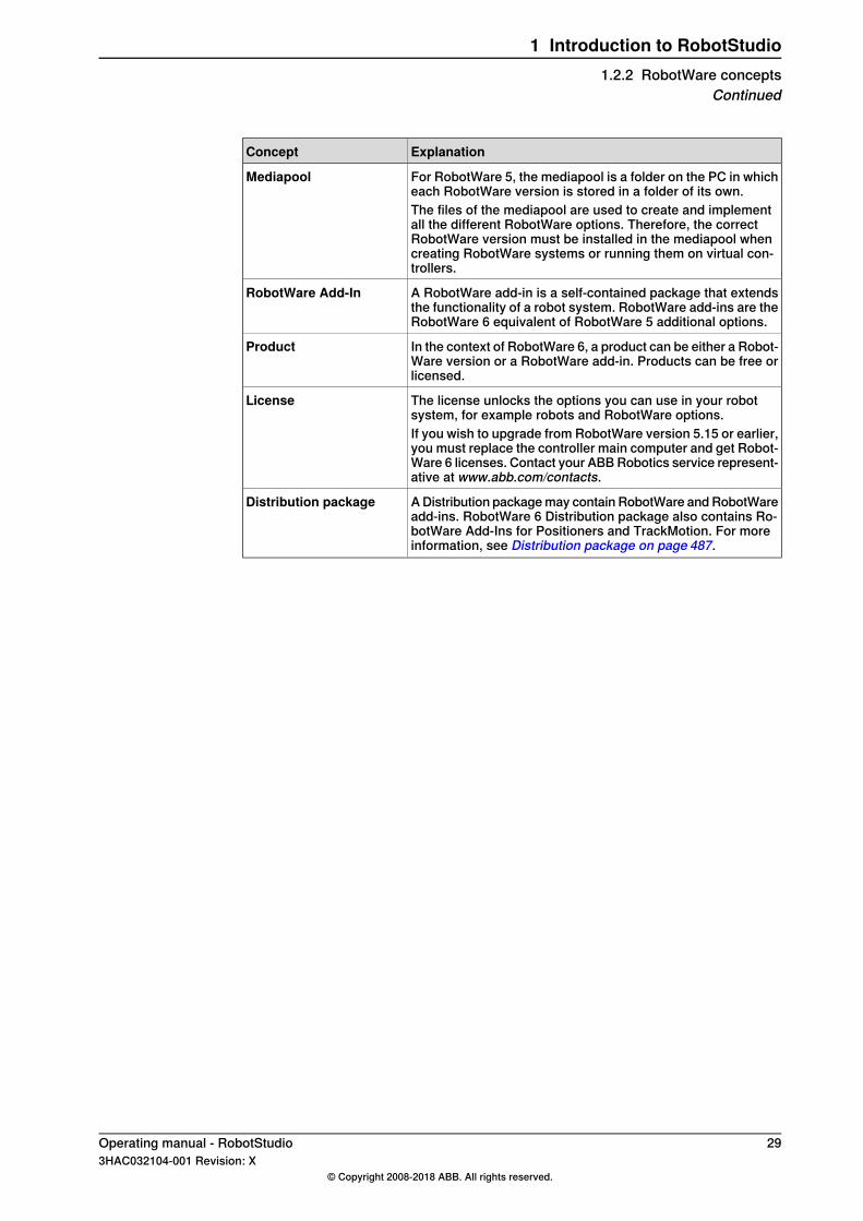
For RobotWare 5, the mediapool is a folder on the PC in whicheach RobotWare version is stored in a folder of its own.
Mediapool
The files of the mediapool are used to create and implementall the different RobotWare options. Therefore, the correctRobotWare version must be installed in the mediapool whencreating RobotWare systems or running them on virtual con-trollers.
A RobotWare add-in is a self-contained package that extendsthe functionality of a robot system. RobotWare add-ins are theRobotWare 6 equivalent of RobotWare 5 additional options.
RobotWare Add-In
In the context of RobotWare 6, a product can be either a Robot-Ware version or a RobotWare add-in. Products can be free orlicensed.
Product
The license unlocks the options you can use in your robotsystem, for example robots and RobotWare options.
License
If you wish to upgrade from RobotWare version 5.15 or earlier,you must replace the controller main computer and get Robot-Ware 6 licenses. Contact your ABB Robotics service represent-ative at www.abb.com/contacts.
A Distribution package may contain RobotWare and RobotWareadd-ins. RobotWare 6 Distribution package also contains Ro-botWare Add-Ins for Positioners and TrackMotion. For moreinformation, see Distribution package on page 487.
Distribution package
Operating manual - RobotStudio 293HAC032104-001 Revision: X
© Copyright 2008-2018 ABB. All rights reserved.
1 Introduction to RobotStudio1.2.2 RobotWare concepts
Continued
1.2.3 RAPID concepts
OverviewThis section introduces the basic terminology of RAPID. The manuals related toRAPID and programming are listed in References on page 14.
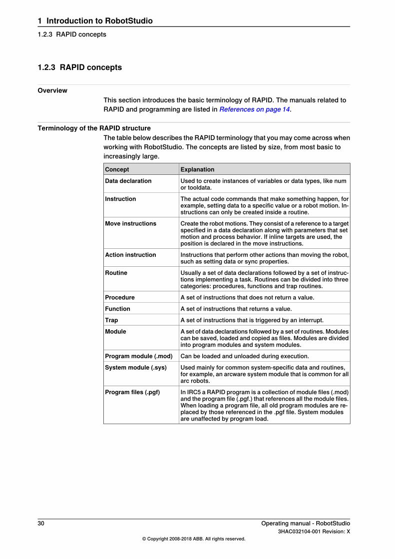
Terminology of the RAPID structureThe table below describes the RAPID terminology that you may come across whenworking with RobotStudio. The concepts are listed by size, from most basic toincreasingly large.
ExplanationConcept
Used to create instances of variables or data types, like numor tooldata.
Data declaration
The actual code commands that make something happen, forexample, setting data to a specific value or a robot motion. In-structions can only be created inside a routine.
Instruction
Create the robot motions. They consist of a reference to a targetspecified in a data declaration along with parameters that setmotion and process behavior. If inline targets are used, theposition is declared in the move instructions.
Move instructions
Instructions that perform other actions than moving the robot,such as setting data or sync properties.
Action instruction
Usually a set of data declarations followed by a set of instruc-tions implementing a task. Routines can be divided into threecategories: procedures, functions and trap routines.
Routine
A set of instructions that does not return a value.Procedure
A set of instructions that returns a value.Function
A set of instructions that is triggered by an interrupt.Trap
A set of data declarations followed by a set of routines. Modulescan be saved, loaded and copied as files. Modules are dividedinto program modules and system modules.
Module
Can be loaded and unloaded during execution.Program module (.mod)
Used mainly for common system-specific data and routines,for example, an arcware system module that is common for allarc robots.
System module (.sys)
In IRC5 a RAPID program is a collection of module files (.mod)and the program file (.pgf.) that references all the module files.When loading a program file, all old program modules are re-placed by those referenced in the .pgf file. System modulesare unaffected by program load.
Program files (.pgf)
30 Operating manual - RobotStudio3HAC032104-001 Revision: X
© Copyright 2008-2018 ABB. All rights reserved.
1 Introduction to RobotStudio1.2.3 RAPID concepts
1.2.4 Concepts of programming
OverviewThis section introduces the terminology regarding programming. The manualsrelated to programming and IRC5 Robots are listed in References on page 14.
Programming conceptsThe table below describes the terminology and concepts that are used in robotprogramming.
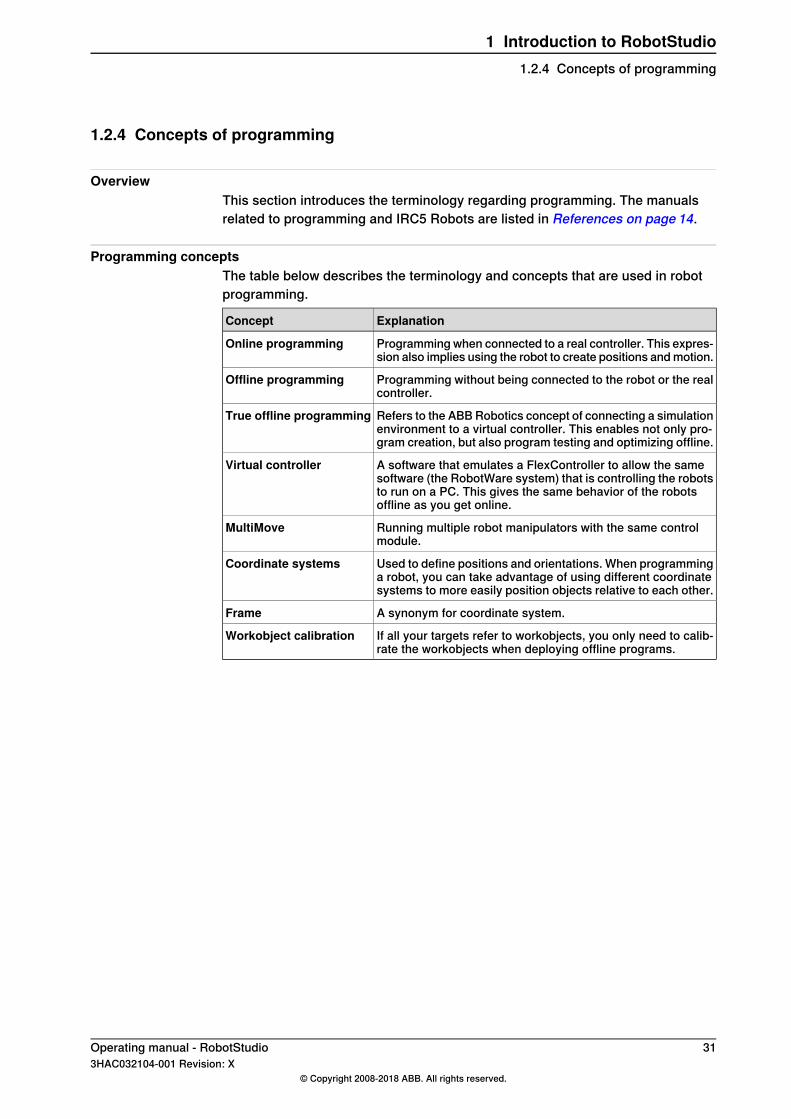
ExplanationConcept
Programming when connected to a real controller. This expres-sion also implies using the robot to create positions and motion.
Online programming
Programming without being connected to the robot or the realcontroller.
Offline programming
Refers to the ABB Robotics concept of connecting a simulationenvironment to a virtual controller. This enables not only pro-gram creation, but also program testing and optimizing offline.
True offline programming
A software that emulates a FlexController to allow the samesoftware (the RobotWare system) that is controlling the robotsto run on a PC. This gives the same behavior of the robotsoffline as you get online.
Virtual controller
Running multiple robot manipulators with the same controlmodule.
MultiMove
Used to define positions and orientations. When programminga robot, you can take advantage of using different coordinatesystems to more easily position objects relative to each other.
Coordinate systems
A synonym for coordinate system.Frame
If all your targets refer to workobjects, you only need to calib-rate the workobjects when deploying offline programs.
Workobject calibration
Operating manual - RobotStudio 313HAC032104-001 Revision: X
© Copyright 2008-2018 ABB. All rights reserved.
1 Introduction to RobotStudio1.2.4 Concepts of programming
1.2.5 Targets and paths
OverviewTargets (positions) and paths (sequences of move instructions to targets) are usedwhen programming robot motions in RobotStudio.When you synchronize the RobotStudio station to the virtual controller, RAPIDprograms are created from the paths.
TargetsA target is a coordinate that the robot shall reach. It contains the followinginformation:
DescriptionInformation
The position of the target, defined in a workobject coordinatesystem, see Coordinate systems on page 33.
Position
The orientation of the target, relative to the orientation of theworkobject. When the robot reaches the target, it will align theTCP’s orientation with the target’s orientation, see Coordinatesystems on page 33.
Orientation
Configuration values that specify how the robot shall reach thetarget. For more information, see Robot axis configurations onpage 39.
Configuration
Targets are converted to instances of the data type robtarget when synchronizedto the virtual controller.
PathsA sequence of move instructions, paths are used to make the robot move along asequence of targets.Paths are converted to procedures when synchronized to the virtual controller.
Move instructionsA move instruction consists of:
• a reference to a target• motion data, such as motion type, speed and zone• a reference to a tooldata• a workobject reference
Action instructionsAn action instruction is a RAPID string that can be used for setting and changingparameters. Action instructions can be inserted before, after or between instructiontargets in paths.
32 Operating manual - RobotStudio3HAC032104-001 Revision: X
© Copyright 2008-2018 ABB. All rights reserved.
1 Introduction to RobotStudio1.2.5 Targets and paths
1.2.6 Coordinate systems
OverviewThis section provides an introduction to the coordinate systems used mostly foroffline programming. In RobotStudio, you can either use the coordinate systems(that are explained below) or the user-defined coordinated systems for co-relatingelements and objects.
HierarchyThe coordinate systems are co-related hierarchically. The origin of each coordinatesystem is defined as a position in one of its ancestries. The following are thedescriptions of the commonly used coordinate systems.
Tool Center Point Coordinate systemThe tool center point coordinate system, also called TCP, is the center point of thetool. You can define different TCPs for one robot. All robots have one predefinedTCP at the robot’s tool mounting point, called tool0.When a program runs, the robot moves the TCP to the programmed position.
RobotStudio World Coordinate systemThe RobotStudio world coordinate system represents the entire station or robotcell. This is the top of the hierarchy to which all other coordinate systems are related(when using RobotStudio).
Base Frame (BF)The base coordinate system is called the Base Frame (BF). Each robot in thestation, both in RobotStudio and the real world has a base coordinate system whichis always located at the base of the robot.
Task Frame (TF)The Task Frame represents the origin of the robot controller world coordinatesystem in RobotStudio.The following picture illustrates the difference between the base frame and thetask frame.
Continues on next pageOperating manual - RobotStudio 333HAC032104-001 Revision: X
© Copyright 2008-2018 ABB. All rights reserved.
1 Introduction to RobotStudio1.2.6 Coordinate systems
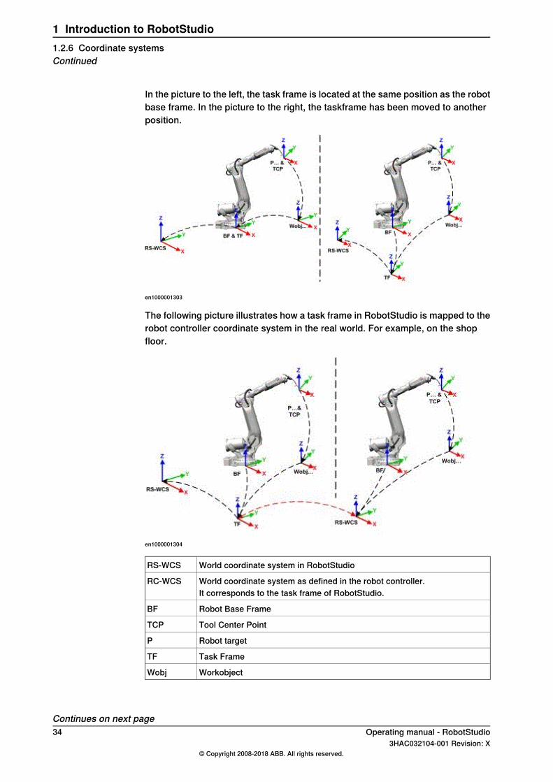
In the picture to the left, the task frame is located at the same position as the robotbase frame. In the picture to the right, the taskframe has been moved to anotherposition.
en1000001303
The following picture illustrates how a task frame in RobotStudio is mapped to therobot controller coordinate system in the real world. For example, on the shopfloor.
en1000001304
World coordinate system in RobotStudioRS-WCS
World coordinate system as defined in the robot controller.RC-WCSIt corresponds to the task frame of RobotStudio.
Robot Base FrameBF
Tool Center PointTCP
Robot targetP
Task FrameTF
WorkobjectWobj
Continues on next page34 Operating manual - RobotStudio
3HAC032104-001 Revision: X© Copyright 2008-2018 ABB. All rights reserved.
1 Introduction to RobotStudio1.2.6 Coordinate systemsContinued

Stations with multiple robot systemsFor a single robot system, RobotStudio’s task frame corresponds to the robotcontroller world coordinate system. When several controllers are present in thestation, the task frame allows the connected robots to work in different coordinatesystems. That is, the robots can be located independent of each other by definingdifferent task frames for each robot.
en1000001442
World coordinate system in RobotStudioRS-WCS
Tool Center Point of robot 1TCP(R1)
Tool Center Point of robot 2TCP(R2)
Base Frame of robot system 1BF(R1)
Base Frame of robot system 2BF(R2)
Robot target 1P1
Robot target 2P2
Task Frame of robot system 1TF1
Task Frame of robot system 2TF2
WorkobjectWobj
Continues on next pageOperating manual - RobotStudio 353HAC032104-001 Revision: X
© Copyright 2008-2018 ABB. All rights reserved.
1 Introduction to RobotStudio1.2.6 Coordinate systems
Continued
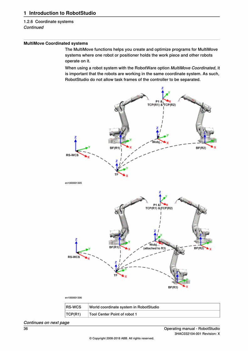
MultiMove Coordinated systemsThe MultiMove functions helps you create and optimize programs for MultiMovesystems where one robot or positioner holds the work piece and other robotsoperate on it.When using a robot system with the RobotWare option MultiMove Coordinated, itis important that the robots are working in the same coordinate system. As such,RobotStudio do not allow task frames of the controller to be separated.
en1000001305
en1000001306
World coordinate system in RobotStudioRS-WCS
Tool Center Point of robot 1TCP(R1)
Continues on next page36 Operating manual - RobotStudio
3HAC032104-001 Revision: X© Copyright 2008-2018 ABB. All rights reserved.
1 Introduction to RobotStudio1.2.6 Coordinate systemsContinued
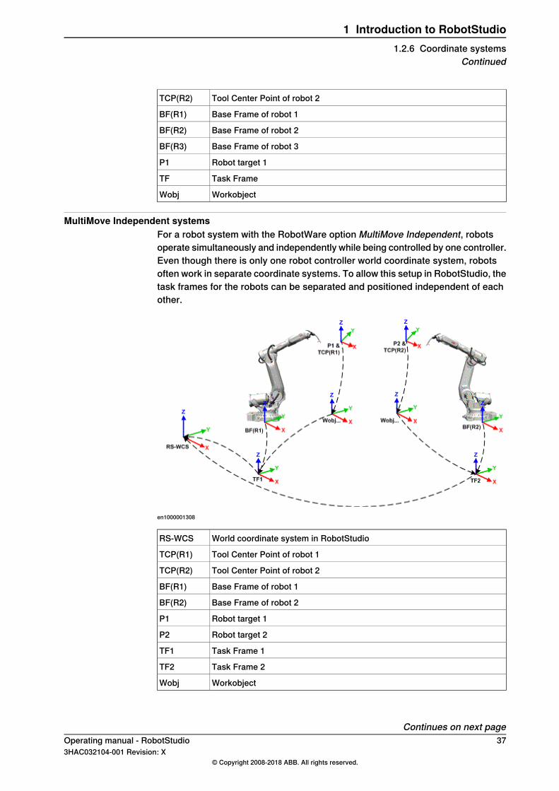
Tool Center Point of robot 2TCP(R2)
Base Frame of robot 1BF(R1)
Base Frame of robot 2BF(R2)
Base Frame of robot 3BF(R3)
Robot target 1P1
Task FrameTF
WorkobjectWobj
MultiMove Independent systemsFor a robot system with the RobotWare option MultiMove Independent, robotsoperate simultaneously and independently while being controlled by one controller.Even though there is only one robot controller world coordinate system, robotsoften work in separate coordinate systems. To allow this setup in RobotStudio, thetask frames for the robots can be separated and positioned independent of eachother.
en1000001308
World coordinate system in RobotStudioRS-WCS
Tool Center Point of robot 1TCP(R1)
Tool Center Point of robot 2TCP(R2)
Base Frame of robot 1BF(R1)
Base Frame of robot 2BF(R2)
Robot target 1P1
Robot target 2P2
Task Frame 1TF1
Task Frame 2TF2
WorkobjectWobj
Continues on next pageOperating manual - RobotStudio 373HAC032104-001 Revision: X
© Copyright 2008-2018 ABB. All rights reserved.
1 Introduction to RobotStudio1.2.6 Coordinate systems
Continued

Workobject coordinate systemThe workobject normally represents the physical work piece. It is composed of twocoordinate systems: the User frame and the Object frame, where the latter is achild to the former. When programming a robot, all targets (positions) are relatedto the object frame of a workobject. If no other workobject is specified, the targetswill be related to the default Wobj0, which always coincides with the base frameof the robot.Using workobjects provides the chance to easily adjust robot programs with anoffset, if the location of the work piece has been changed. Thus, workobjects canbe used for calibrating offline programs. If the placement of the fixture or workpiece relative to the robot in the real station does not completely match theplacement in the offline station, you simply adjust the position of the workobject.Workobjects are also used for coordinated motion. If a workobject is attached toa mechanical unit (and the system uses the option for coordinated motion), therobot will find the targets in the workobject even when the mechanical unit movesthe workobject.In the picture below the grey coordinate system is the world coordinate system,and the black ones are the object frame and the user frame of the workobject. Herethe user frame is positioned at the table or fixture and the object frame at theworkpiece.
xx0500001519
User coordinate systemsUser coordinate systems are used for creating reference points of your choice.For example, you can create user coordinate systems at strategic points in thework piece to simplify programming.
38 Operating manual - RobotStudio3HAC032104-001 Revision: X
© Copyright 2008-2018 ABB. All rights reserved.
1 Introduction to RobotStudio1.2.6 Coordinate systemsContinued
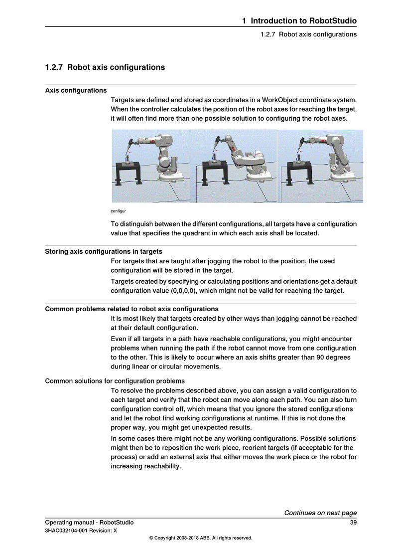
1.2.7 Robot axis configurations
Axis configurationsTargets are defined and stored as coordinates in a WorkObject coordinate system.When the controller calculates the position of the robot axes for reaching the target,it will often find more than one possible solution to configuring the robot axes.
configur
To distinguish between the different configurations, all targets have a configurationvalue that specifies the quadrant in which each axis shall be located.
Storing axis configurations in targetsFor targets that are taught after jogging the robot to the position, the usedconfiguration will be stored in the target.Targets created by specifying or calculating positions and orientations get a defaultconfiguration value (0,0,0,0), which might not be valid for reaching the target.
Common problems related to robot axis configurationsIt is most likely that targets created by other ways than jogging cannot be reachedat their default configuration.Even if all targets in a path have reachable configurations, you might encounterproblems when running the path if the robot cannot move from one configurationto the other. This is likely to occur where an axis shifts greater than 90 degreesduring linear or circular movements.
Common solutions for configuration problemsTo resolve the problems described above, you can assign a valid configuration toeach target and verify that the robot can move along each path. You can also turnconfiguration control off, which means that you ignore the stored configurationsand let the robot find working configurations at runtime. If this is not done theproper way, you might get unexpected results.In some cases there might not be any working configurations. Possible solutionsmight then be to reposition the work piece, reorient targets (if acceptable for theprocess) or add an external axis that either moves the work piece or the robot forincreasing reachability.
Continues on next pageOperating manual - RobotStudio 393HAC032104-001 Revision: X
© Copyright 2008-2018 ABB. All rights reserved.
1 Introduction to RobotStudio1.2.7 Robot axis configurations
How configurations are denotedThe robot’s axis configurations are denoted by a series of four integers, specifyingin which quadrant of a full revolution significant axes are located. The quadrantsare numbered from zero for positive (counterclockwise) rotation and from -1 fornegative (clockwise) rotation.For a linear axis, the integer specifies the range (in meters) from the neutral positionin which the axis is located.A configuration for a six-axis industrial robot (like IRB 140) may look like:
[0-121]
The first integer (0) specifies the position of axis 1: somewhere in the first positivequadrant (between 0 and 90 degrees rotation).The second integer (-1) specifies the position of axis 4: somewhere in the firstnegative quadrant (between 0 and -90 degrees rotation).The third integer (2) specifies the position of axis 6: somewhere in the third positivequadrant (between 180 and 270 degrees rotation).The fourth integer (1) specifies the position of axis x, a virtual axis used forspecifying the wrist center in relation to other axes.
Configuration controlWhen executing a robot program, you can choose whether to control configurationvalues. If configuration control is turned off, configuration values stored with thetargets are ignored, and the robot will use the configuration closest its currentconfiguration for reaching the target. If turned on, it will only use the specifiedconfiguration for reaching the targets.Configuration control can be turned off and on for joint and linear movementsindependently and is controlled by the ConfJ and ConfL action instructions.
Turning configuration control offRunning a program without configuration control may result in differentconfigurations each time a cycle is executed: When the robot returns to the startposition after completing a cycle, it may choose a different configuration than theoriginal.For programs with linear move instructions this might cause a situation where therobot gets closer and closer its joint limits and eventually will not be able to reachthe target.For programs with joint move instructions this might cause sweeping, unpredictablemovements.
Turning configuration control onRunning a program with configuration control forces the robot to use theconfigurations stored with the targets. This results in predictable cycles andpredictable motions. In some situations, however, like when the robot moves to atarget from an unknown position, using configuration control may limit the robot’sreachability.When programming offline, you must assign a configuration to each target if theprogram shall be executed with configuration control.
40 Operating manual - RobotStudio3HAC032104-001 Revision: X
© Copyright 2008-2018 ABB. All rights reserved.
1 Introduction to RobotStudio1.2.7 Robot axis configurationsContinued
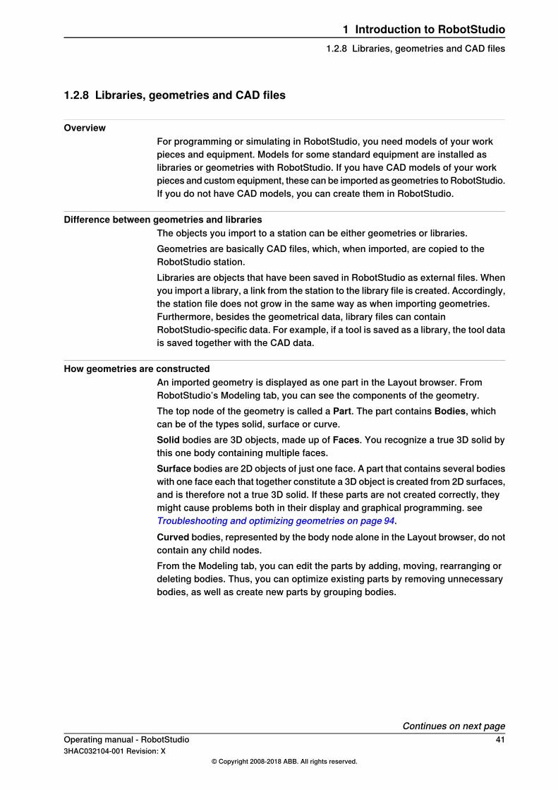
1.2.8 Libraries, geometries and CAD files
OverviewFor programming or simulating in RobotStudio, you need models of your workpieces and equipment. Models for some standard equipment are installed aslibraries or geometries with RobotStudio. If you have CAD models of your workpieces and custom equipment, these can be imported as geometries to RobotStudio.If you do not have CAD models, you can create them in RobotStudio.
Difference between geometries and librariesThe objects you import to a station can be either geometries or libraries.Geometries are basically CAD files, which, when imported, are copied to theRobotStudio station.Libraries are objects that have been saved in RobotStudio as external files. Whenyou import a library, a link from the station to the library file is created. Accordingly,the station file does not grow in the same way as when importing geometries.Furthermore, besides the geometrical data, library files can containRobotStudio-specific data. For example, if a tool is saved as a library, the tool datais saved together with the CAD data.
How geometries are constructedAn imported geometry is displayed as one part in the Layout browser. FromRobotStudio’s Modeling tab, you can see the components of the geometry.The top node of the geometry is called a Part. The part contains Bodies, whichcan be of the types solid, surface or curve.Solid bodies are 3D objects, made up of Faces. You recognize a true 3D solid bythis one body containing multiple faces.Surface bodies are 2D objects of just one face. A part that contains several bodieswith one face each that together constitute a 3D object is created from 2D surfaces,and is therefore not a true 3D solid. If these parts are not created correctly, theymight cause problems both in their display and graphical programming. seeTroubleshooting and optimizing geometries on page 94.Curved bodies, represented by the body node alone in the Layout browser, do notcontain any child nodes.From the Modeling tab, you can edit the parts by adding, moving, rearranging ordeleting bodies. Thus, you can optimize existing parts by removing unnecessarybodies, as well as create new parts by grouping bodies.
Continues on next pageOperating manual - RobotStudio 413HAC032104-001 Revision: X
© Copyright 2008-2018 ABB. All rights reserved.
1 Introduction to RobotStudio1.2.8 Libraries, geometries and CAD files
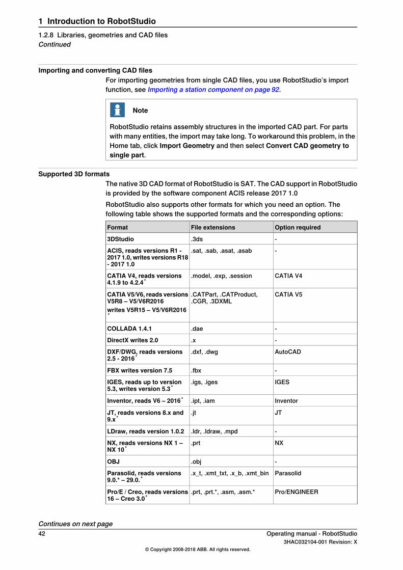
Importing and converting CAD filesFor importing geometries from single CAD files, you use RobotStudio’s importfunction, see Importing a station component on page 92.
Note
RobotStudio retains assembly structures in the imported CAD part. For partswith many entities, the import may take long. To workaround this problem, in theHome tab, click Import Geometry and then select Convert CAD geometry tosingle part.
Supported 3D formatsThe native 3D CAD format of RobotStudio is SAT. The CAD support in RobotStudiois provided by the software component ACIS release 2017 1.0RobotStudio also supports other formats for which you need an option. Thefollowing table shows the supported formats and the corresponding options:
Option requiredFile extensionsFormat
-.3ds3DStudio
-.sat, .sab, .asat, .asabACIS, reads versions R1 -2017 1.0, writes versions R18- 2017 1.0
CATIA V4.model, .exp, .sessionCATIA V4, reads versions4.1.9 to 4.2.4 *
CATIA V5.CATPart, .CATProduct,.CGR, .3DXML
CATIA V5/V6, reads versionsV5R8 – V5/V6R2016writes V5R15 – V5/V6R2016*
-.daeCOLLADA 1.4.1
-.xDirectX writes 2.0
AutoCAD.dxf, .dwgDXF/DWG, reads versions2.5 - 2016 *
-.fbxFBX writes version 7.5
IGES.igs, .igesIGES, reads up to version5.3, writes version 5.3 *
Inventor.ipt, .iamInventor, reads V6 – 2016 *
JT.jtJT, reads versions 8.x and9.x *
-.ldr, .ldraw, .mpdLDraw, reads version 1.0.2
NX.prtNX, reads versions NX 1 –NX 10 *
-.objOBJ
Parasolid.x_t, .xmt_txt, .x_b, .xmt_binParasolid, reads versions9.0.* – 29.0. *
Pro/ENGINEER.prt, .prt.*, .asm, .asm.*Pro/E / Creo, reads versions16 – Creo 3.0 *
Continues on next page42 Operating manual - RobotStudio
3HAC032104-001 Revision: X© Copyright 2008-2018 ABB. All rights reserved.
1 Introduction to RobotStudio1.2.8 Libraries, geometries and CAD filesContinued
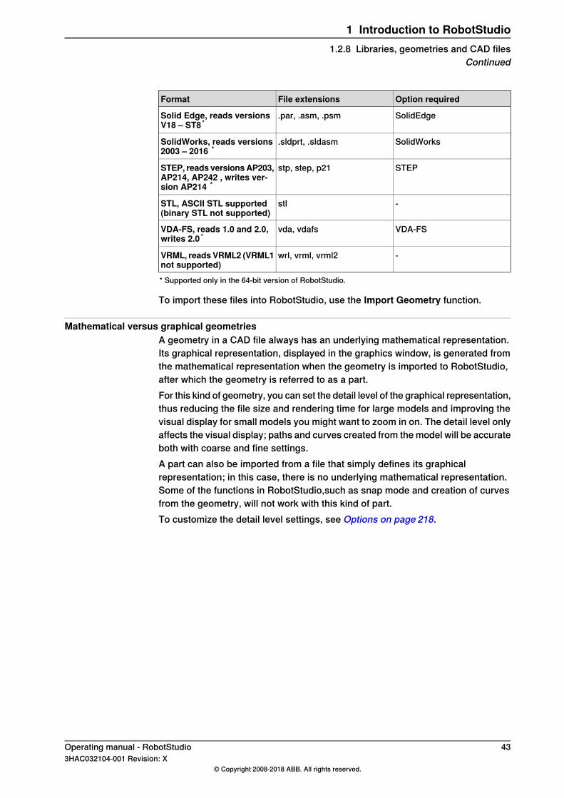
Option requiredFile extensionsFormat
SolidEdge.par, .asm, .psmSolid Edge, reads versionsV18 – ST8 *
SolidWorks.sldprt, .sldasmSolidWorks, reads versions2003 – 2016 *
STEPstp, step, p21STEP, reads versionsAP203,AP214, AP242 , writes ver-sion AP214 *
-stlSTL, ASCII STL supported(binary STL not supported)
VDA-FSvda, vdafsVDA-FS, reads 1.0 and 2.0,writes 2.0 *
-wrl, vrml, vrml2VRML, reads VRML2 (VRML1not supported)* Supported only in the 64-bit version of RobotStudio.
To import these files into RobotStudio, use the Import Geometry function.
Mathematical versus graphical geometriesA geometry in a CAD file always has an underlying mathematical representation.Its graphical representation, displayed in the graphics window, is generated fromthe mathematical representation when the geometry is imported to RobotStudio,after which the geometry is referred to as a part.For this kind of geometry, you can set the detail level of the graphical representation,thus reducing the file size and rendering time for large models and improving thevisual display for small models you might want to zoom in on. The detail level onlyaffects the visual display; paths and curves created from the model will be accurateboth with coarse and fine settings.A part can also be imported from a file that simply defines its graphicalrepresentation; in this case, there is no underlying mathematical representation.Some of the functions in RobotStudio,such as snap mode and creation of curvesfrom the geometry, will not work with this kind of part.To customize the detail level settings, see Options on page 218.
Operating manual - RobotStudio 433HAC032104-001 Revision: X
© Copyright 2008-2018 ABB. All rights reserved.
1 Introduction to RobotStudio1.2.8 Libraries, geometries and CAD files
Continued

1.3 Installing and licensing RobotStudio
1.3.1 Installation options and prerequisites
PrerequisitesYou should have administrator privileges on the PC before installing RobotStudio.
Installation optionsYou can download RobotStudio fromhttp://new.abb.com/products/robotics/robotstudio/downloads, and install it.RobotStudio offers the following installation options:
• Minimal - Installs only the features required to program, configure, andmonitor a real controller connected over Ethernet.
• Complete - Installs all the features required to run the complete RobotStudio.If installed with this option, additional features of Basic and Premiumfunctionality are available.
• Custom - Installs user-customized features. This option allows excludingunwanted robot libraries.
Note
Both the 32 and 64-bit versions of RobotStudio are installed for the Completeinstallation option on computers that have a 64-bit operating system. The 64-bitedition allows large CAD-models to be imported as it can address more memorythan the 32-bit version.However, the 64-bit edition has the following limitations:
• ScreenMaker and Integrated Vision are not supported.• Add-ins will be loaded from the following folder
C:\Program Files (x86)\ABB Industrial IT\Robotics
IT\RobotStudio 6.04\Bin64\Addins
Installing RobotWareA matching RobotWare version will be installed with RobotStudio. You can downloadand install additional RobotWare versions through RobotStudio when connectedto the Internet. In theAdd-Ins tab, clickRobotApps. The RobotWare section showsthe RobotWare versions available for downloading.
44 Operating manual - RobotStudio3HAC032104-001 Revision: X
© Copyright 2008-2018 ABB. All rights reserved.
1 Introduction to RobotStudio1.3.1 Installation options and prerequisites
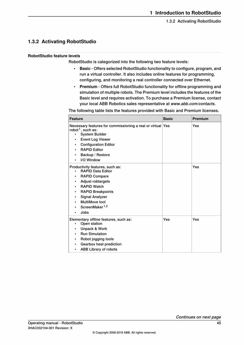
1.3.2 Activating RobotStudio
RobotStudio feature levelsRobotStudio is categorized into the following two feature levels:
• Basic - Offers selected RobotStudio functionality to configure, program, andrun a virtual controller. It also includes online features for programming,configuring, and monitoring a real controller connected over Ethernet.
• Premium - Offers full RobotStudio functionality for offline programming andsimulation of multiple robots. The Premium level includes the features of theBasic level and requires activation. To purchase a Premium license, contactyour local ABB Robotics sales representative at www.abb.com/contacts.
The following table lists the features provided with Basic and Premium licenses.
PremiumBasicFeature
YesYesNecessary features for commissioning a real or virtualrobot1 , such as:
• System Builder• Event Log Viewer• Configuration Editor• RAPID Editor• Backup / Restore• I/O Window
YesProductivity features, such as:• RAPID Data Editor• RAPID Compare• Adjust robtargets• RAPID Watch• RAPID Breakpoints• Signal Analyzer• MultiMove tool• ScreenMaker1,2
• Jobs
YesYesElementary offline features, such as:• Open station• Unpack & Work• Run Simulation• Robot jogging tools• Gearbox heat prediction• ABB Library of robots
Continues on next pageOperating manual - RobotStudio 453HAC032104-001 Revision: X
© Copyright 2008-2018 ABB. All rights reserved.
1 Introduction to RobotStudio1.3.2 Activating RobotStudio

PremiumBasicFeature
YesAdvanced offline features, such as:• Graphical programming• Save station• Go Offline• Pack & Go• Import / Export Geometry• Import Library• Create station viewer and movies• Transfer• AutoPath• 3D operations• Virtual Reality
YesAdd-Ins
1. Requires the RobotWare option PC Interface on the real robot controller system to enableLAN communication. The option is not needed for connection via the Service port or forvirtual controller communication.2. Requires the RobotWare option FlexPendant Interface on the robot controller system
In addition to the Premium functionality, add-ins like PowerPacs is also available.• PowerPacs provide enhanced features for selected applications.
Activating RobotStudioThe activation procedures are different for standalone and network licenses. If youhave a standalone license, refer Activating a standalone license on page 46 andif you have a network license, refer Activating a network license on page 47.
Note
If you accidentally activate a network license through the standalone activationprocedure, the license becomes invalid. You must contact ABB for support.
Activating a standalone licenseStandalone licenses are activated through the Activation Wizard. If your computerhas Internet access, RobotStudio gets activated automatically, otherwise manualactivation is required.Use the following steps to start the Activation Wizard.
1 Click the File tab, and then click the Help section.2 Under Support, click Manage Licenses. The Options dialog appears with
the Licensing options.3 Under Licensing, clickActivationWizard to view RobotStudio license options.
Note
To resolve issues during activation, contact your local ABB customer supportrepresentative at the e-mail address or telephone number provided atwww.abb.com/contacts. Alternatively, with your activation key attached, sendan e-mail to [email protected].
Continues on next page46 Operating manual - RobotStudio
3HAC032104-001 Revision: X© Copyright 2008-2018 ABB. All rights reserved.
1 Introduction to RobotStudio1.3.2 Activating RobotStudioContinued

With Internet accessWhen your computer is connected to Internet, the Activation Wizard automaticallysends your activation request to the ABB licensing servers. Your license will thenbe automatically installed and your product will be ready for use. RobotStudio mustbe restarted after activation.
Without Internet accessIf your computer is not connected to Internet, you must proceed with manualactivation.
1 Create a license request file by selecting the option Step 1:Create a licenserequest file.Proceed through the wizard, enter your activation key and save the licenserequest file to your computer.
2 Use removable storage, such as a USB stick, to transfer the file to a computerwith an Internet connection. On that computer, open a web browser, go tohttp://manualactivation.e.abb.com/ and follow the instructions given.The result will be a license key file that should be saved and transferred backto the computer having the installation awaiting activation.
3 Relaunch the activation wizard and go through the steps until you reach theActivate a Standalone License page.
4 Under Manual Activation, select the option Step 3:Install a license file.Proceed through the wizard, selecting the license key file when requested.Upon completion, RobotStudio is activated and ready for use.
RobotStudio must be restarted after the activation.
Activating a network licenseNetwork licensing allows you to centralize license management by installing licenseson a single server rather than on each individual client machine. The serveradministers the licenses to the clients as required. A single network license allowsseveral clients to use the software.Network Licensing is set up in the following stages:
1 Install the server for network licensing (See Installing the Network LicensingServer on page 48)
2 Activate the licenses for network licensing (See Using the SLP Server WebInterface on page 48)
3 Set up the client for network licensing (See Setting up Network Licensing inthe client on page 50)
Tip
Network licenses are displayed as Network in the View Installed Licenses linkof the Licensing page.
Continues on next pageOperating manual - RobotStudio 473HAC032104-001 Revision: X
© Copyright 2008-2018 ABB. All rights reserved.
1 Introduction to RobotStudio1.3.2 Activating RobotStudio
Continued

Installing the Network Licensing ServerNetwork licensing in RobotStudio uses the SLP Distributor server as the networklicensing server. It manages the allocation of network licenses to the clients.You can install the SLP Distributor server from the Utilities\SLP Distributor directoryof the RobotStudio distribution.
Note
You need administrative privileges for installing and configuring the SLPDistribution server. The installer requires the following details:
• Windows Server 2012 or 2008, Windows 8, Windows 7, or Windows Vista• .NET Framework 3.5 SP1
The SLP Distributor server is installed as a service that starts automatically withWindows. It requires two open TCP ports, by default 2468 (for the web interface)and 8731 (for licensing). The installer opens these ports in the standard WindowsFirewall, but any third-party firewall must be configured manually by the systemadministrator.
Using the SLP Server Web InterfaceOnce the SLP server is online, you can access its web interface on the addresshttp://<server>:2468/web.The following table shows how to use the server's web interface.
Use...To...
The Activation tab.Activate a network license auto-matically(for PCs with Internet connection)
Type in the Activation Key provided by ABB, and thenclick Submit.The number of concurrent users activated depends onthe activation key provided.
xx1300000052
Continues on next page48 Operating manual - RobotStudio
3HAC032104-001 Revision: X© Copyright 2008-2018 ABB. All rights reserved.
1 Introduction to RobotStudio1.3.2 Activating RobotStudioContinued

Use...To...
The Activation tab.1 Click Manual Activation.2 Type in your activation key provided by ABB, and
then click Submit.3 Save the file to a removable storage, such as a
USB stick, then transfer the file to a machine withan Internet connection. On that machine, open aweb browser and browse to http://manualactiva-tion.e.abb.com/ and follow the instructions given.A license key file will be generated and saved andwill be returned to the machine which hosts theinstallation.
4 Once you recieve the license file, click Browse toupload and install the license file.
Your network license is now activated.
xx1300000051
Activate a network license manu-ally(for PCs without Internet connec-tion)
In the Home tab, under Dashboard, click Details.Alternatively, click the Products tab.The Product details for RobotStudio page opens whichshows the installed licenses details.
View the installed licenses
In the Home tab, under Dashboard, click Usage.Alternatively, click the Usage tab.The Current usage of RobotStudio page opens in whichthe following details are tabulated.
• Licenses which are currently allocated• Client to which each license is allocated to• Number of remaining licenses available for use
Each table row corresponds to one client system.
View the usage of licenses
Continues on next pageOperating manual - RobotStudio 493HAC032104-001 Revision: X
© Copyright 2008-2018 ABB. All rights reserved.
1 Introduction to RobotStudio1.3.2 Activating RobotStudio
Continued

Note
Certain proxy issues upon activation in the web interface of SLP server mayproduce a message which only statesActivation failed. This issue happens whenthe system account that executes SLP-Distributor-service does not have therights to read the user profile. As a workaround, follow this procedure:
1 Open the Services control panel (services.msc)2 Open properties for Software Potential Distributor3 Change Log on as to an actual named user, preferably the currently logged
on user4 Restart the service and re-attempt an activation.5 After your re-attempt, change Log on as back to Local System account and
restart the service.
Setting up Network Licensing in the client
Note
You require Administrative privileges to store this configuration.
You need to use the RobotStudio Activation Wizard in the client system for settingup Network Licensing.Use this procedure to set up Network Licensing for a client system.
Action
On the File tab, click Options and go to General:Licensing.1
On the Licensing page to the right, click Activation wizard to launch the ActivationWizard.
2
In the Activation Wizard, on the Activate RobotStudio page, choose the option I want tospecify a network license server and manage server license, and then click Next.
3
You will proceed to the License Server page.
Specify the name or IP address of the License Server, and then click Finish.4If Windows UAC is enabled, a confirmation dialog appears. This prompts you to restartRobotStudio in order to start using the specified server.To go to the SLP Distributor server web interface, click the Open the server dashboardlink. For information about using the server dashboard, see Using the SLP Server WebInterface on page 48.Note that the changes made are not applied until RobotStudio is restarted.
Note
For Network Licensing to work, the client system should be online with the server.For information about enabling licensing while working offline, see UsingCommuter Licenses on page 51.
Continues on next page50 Operating manual - RobotStudio
3HAC032104-001 Revision: X© Copyright 2008-2018 ABB. All rights reserved.
1 Introduction to RobotStudio1.3.2 Activating RobotStudioContinued

Using Commuter LicensesCommuter licenses allow a client system to work offline from the license server.You can check out a license from the server for a specified number of days. Duringthis period the checked out license is unavailable to other users. The commuterlicense is made available for other clients only when it is manually checked in backto the server.The commuter license in the client system expires when the check out time expires.In this case, on starting RobotStudio in the client system, the Network Licensedialog opens automatically and prompts you to check in the license back to theserver.
Note
It is not possible to check out specific features in the license. All features in alicense are included when it is checked out.
To check in/check out a commuter license, you need to use the Activation Wizard.Use this procedure to check in/check out a commuter license.
Action
On the File menu, click Options and select General: Licensing1
On the Licensing page to the right, click Activation wizard to launch the ActivationWizard.
2
In the Activation Wizard, on the Activate RobotStudio page, choose I want to check outor check in a commuter license and click Next.
3
You will proceed to the Commuter License page.
UnderCommuter License, you will be presented one of the following options as per yourrequirement:
• Check out a commuter license - In the Check out days box specify the specifythe number of days for which you wish to keep the license.This option is disabled if you already have a commuter license checked out.
• Check in a commuter license - Choose this option to return the currently checkedout license to the server.This option is enabled only if a commuter license is already checked out. If so,the expiration date and time of the license is also displayed.
4
Click Finish to complete the check in/check out.5
Tip
Network licenses that are checked-out as commuter licenses will be displayedas Floating (checked out) in the View Installed Licenses link of the Licensingpage.
Operating manual - RobotStudio 513HAC032104-001 Revision: X
© Copyright 2008-2018 ABB. All rights reserved.
1 Introduction to RobotStudio1.3.2 Activating RobotStudio
Continued
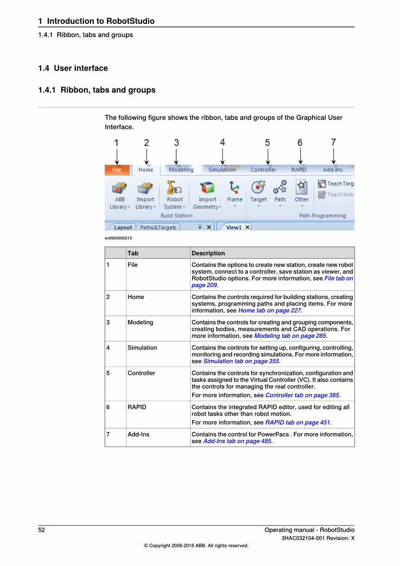
1.4 User interface
1.4.1 Ribbon, tabs and groups
The following figure shows the ribbon, tabs and groups of the Graphical UserInterface.
en0900000215
DescriptionTab
Contains the options to create new station, create new robotsystem, connect to a controller, save station as viewer, andRobotStudio options. For more information, see File tab onpage 209.
File1
Contains the controls required for building stations, creatingsystems, programming paths and placing items. For moreinformation, see Home tab on page 227.
Home2
Contains the controls for creating and grouping components,creating bodies, measurements and CAD operations. Formore information, see Modeling tab on page 285.
Modeling3
Contains the controls for setting up, configuring, controlling,monitoring and recording simulations. For more information,see Simulation tab on page 355.
Simulation4
Contains the controls for synchronization, configuration andtasks assigned to the Virtual Controller (VC). It also containsthe controls for managing the real controller.
Controller5
For more information, see Controller tab on page 385.
Contains the integrated RAPID editor, used for editing allrobot tasks other than robot motion.
RAPID6
For more information, see RAPID tab on page 451.
Contains the control for PowerPacs . For more information,see Add-Ins tab on page 485.
Add-Ins7
52 Operating manual - RobotStudio3HAC032104-001 Revision: X
© Copyright 2008-2018 ABB. All rights reserved.
1 Introduction to RobotStudio1.4.1 Ribbon, tabs and groups

1.4.2 Layout browser
OverviewThe layout browser is a hierarchical display of physical items, such as robots andtools.
Icons
DescriptionNodeIcon
The robot in the station.Robotxx050000
A tool.Toolxx050001
Contains all the links of the objects.Link collectionxx050002
A physical object in a joint connection. Each linkis made up of one or several parts.
Linkxx050003
Contains all the frames for an object.Framesxx050004
A grouping of parts or other assemblies, carryingits own coordinate systems. It is used to structurea station.
Component groupxx050005
A physical object in RobotStudio. Parts withgeometric information are made up of one ormore 2D or 3D entities. Parts without geometricinformation (such as imported .jt files) are empty.
Partxx050006
Contains all collision sets. Each collision set in-cludes two groups of objects.
Collision setxx050007
Contains references to the objects that are sub-ject to collision detection.
Objects groupxx050008
The objects in the collision set.Collision set mechanisms
xx050009
The frames in the station.Frame
xx050010
Operating manual - RobotStudio 533HAC032104-001 Revision: X
© Copyright 2008-2018 ABB. All rights reserved.
1 Introduction to RobotStudio1.4.2 Layout browser
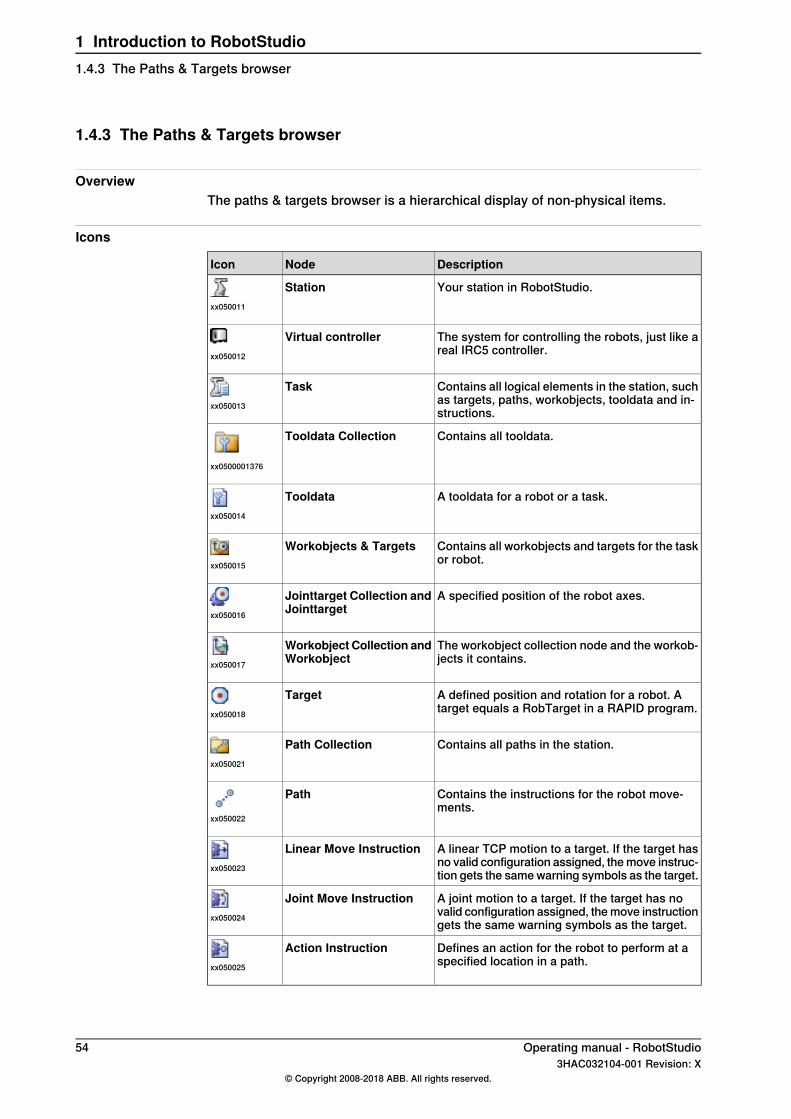
1.4.3 The Paths & Targets browser
OverviewThe paths & targets browser is a hierarchical display of non-physical items.
Icons
DescriptionNodeIcon
Your station in RobotStudio.Stationxx050011
The system for controlling the robots, just like areal IRC5 controller.
Virtual controllerxx050012
Contains all logical elements in the station, suchas targets, paths, workobjects, tooldata and in-structions.
Taskxx050013
Contains all tooldata.Tooldata Collection
xx0500001376
A tooldata for a robot or a task.Tooldataxx050014
Contains all workobjects and targets for the taskor robot.
Workobjects & Targetsxx050015
A specified position of the robot axes.Jointtarget Collection andJointtargetxx050016
The workobject collection node and the workob-jects it contains.
Workobject Collection andWorkobjectxx050017
A defined position and rotation for a robot. Atarget equals a RobTarget in a RAPID program.
Targetxx050018
Contains all paths in the station.Path Collectionxx050021
Contains the instructions for the robot move-ments.
Path
xx050022
A linear TCP motion to a target. If the target hasno valid configuration assigned, the move instruc-tion gets the same warning symbols as the target.
Linear Move Instructionxx050023
A joint motion to a target. If the target has novalid configuration assigned, the move instructiongets the same warning symbols as the target.
Joint Move Instructionxx050024
Defines an action for the robot to perform at aspecified location in a path.
Action Instructionxx050025
54 Operating manual - RobotStudio3HAC032104-001 Revision: X
© Copyright 2008-2018 ABB. All rights reserved.
1 Introduction to RobotStudio1.4.3 The Paths & Targets browser
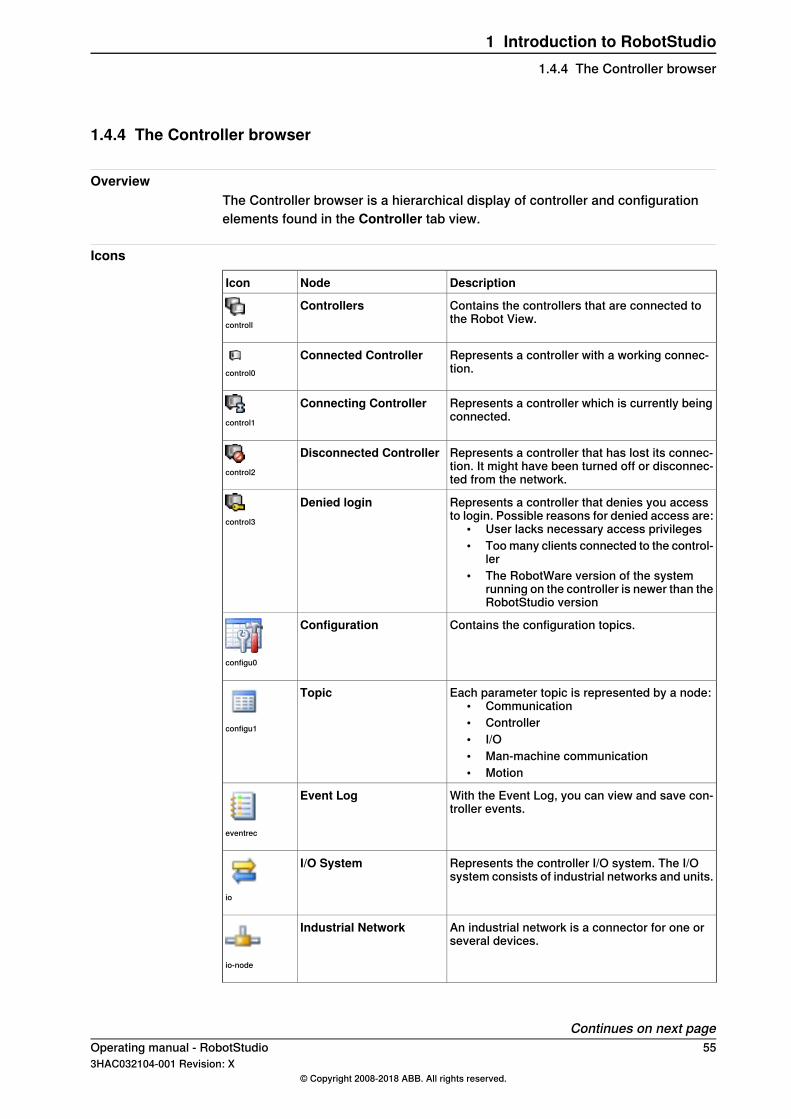
1.4.4 The Controller browser
OverviewThe Controller browser is a hierarchical display of controller and configurationelements found in the Controller tab view.
Icons
DescriptionNodeIcon
Contains the controllers that are connected tothe Robot View.
Controllerscontroll
Represents a controller with a working connec-tion.
Connected Controllercontrol0
Represents a controller which is currently beingconnected.
Connecting Controllercontrol1
Represents a controller that has lost its connec-tion. It might have been turned off or disconnec-ted from the network.
Disconnected Controllercontrol2
Represents a controller that denies you accessto login. Possible reasons for denied access are:
• User lacks necessary access privileges• Too many clients connected to the control-
ler• The RobotWare version of the system
running on the controller is newer than theRobotStudio version
Denied logincontrol3
Contains the configuration topics.Configuration
configu0
Each parameter topic is represented by a node:• Communication• Controller• I/O• Man-machine communication• Motion
Topic
configu1
With the Event Log, you can view and save con-troller events.
Event Log
eventrec
Represents the controller I/O system. The I/Osystem consists of industrial networks and units.
I/O System
io
An industrial network is a connector for one orseveral devices.
Industrial Network
io-node
Continues on next pageOperating manual - RobotStudio 553HAC032104-001 Revision: X
© Copyright 2008-2018 ABB. All rights reserved.
1 Introduction to RobotStudio1.4.4 The Controller browser
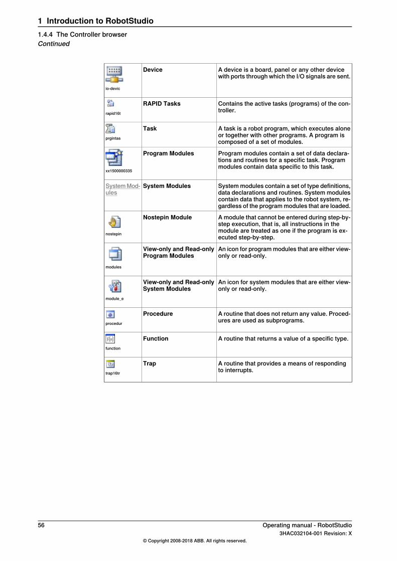
A device is a board, panel or any other devicewith ports through which the I/O signals are sent.
Device
io-devic
Contains the active tasks (programs) of the con-troller.
RAPID Tasksrapid16t
A task is a robot program, which executes aloneor together with other programs. A program iscomposed of a set of modules.
Taskprgintas
Program modules contain a set of data declara-tions and routines for a specific task. Programmodules contain data specific to this task.
Program Modules
xx1500000335
System modules contain a set of type definitions,data declarations and routines. System modulescontain data that applies to the robot system, re-gardless of the program modules that are loaded.
System ModulesSystem Mod-ules
A module that cannot be entered during step-by-step execution, that is, all instructions in themodule are treated as one if the program is ex-ecuted step-by-step.
Nostepin Module
nostepin
An icon for program modules that are either view-only or read-only.
View-only and Read-onlyProgram Modules
modules
An icon for system modules that are either view-only or read-only.
View-only and Read-onlySystem Modules
module_e
A routine that does not return any value. Proced-ures are used as subprograms.
Procedureprocedur
A routine that returns a value of a specific type.Functionfunction
A routine that provides a means of respondingto interrupts.
Traptrap16tr
56 Operating manual - RobotStudio3HAC032104-001 Revision: X
© Copyright 2008-2018 ABB. All rights reserved.
1 Introduction to RobotStudio1.4.4 The Controller browserContinued
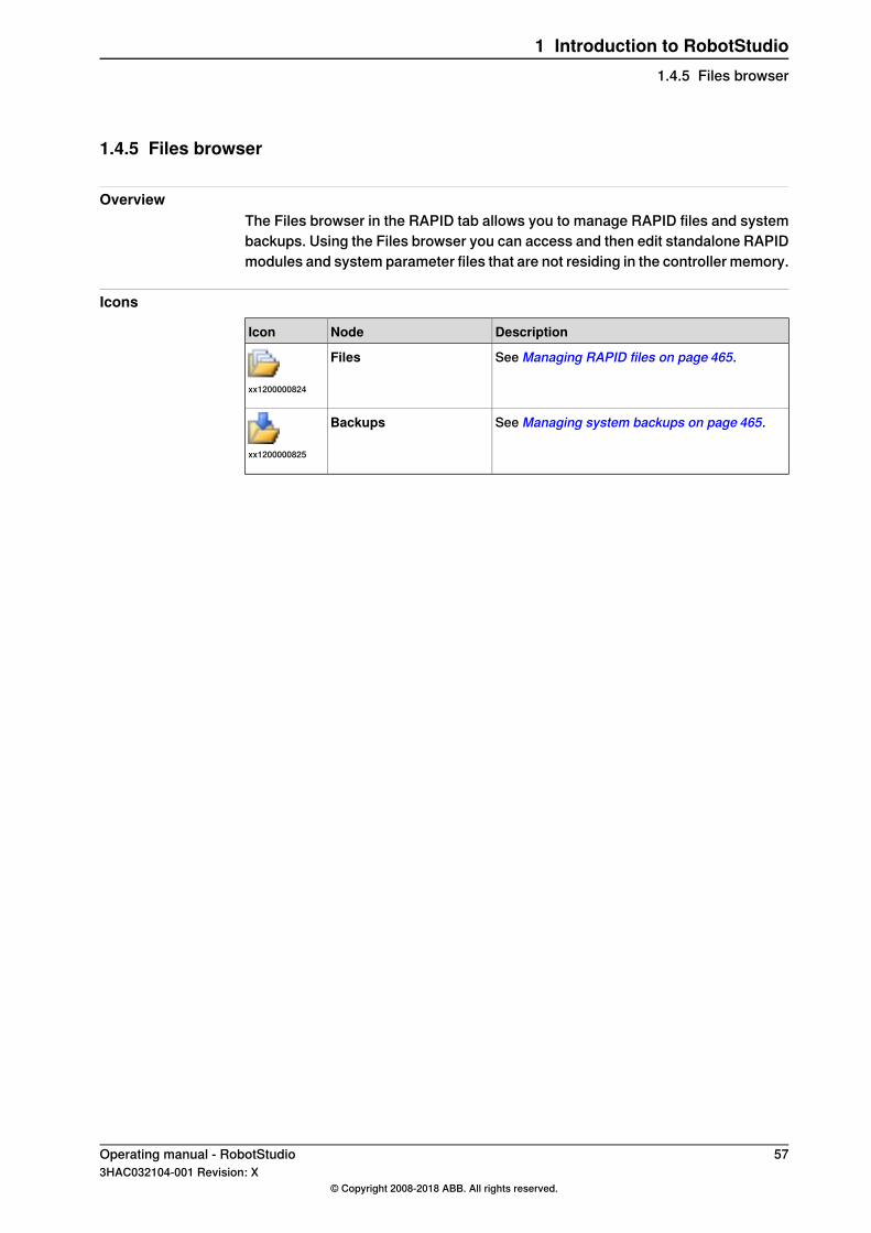
1.4.5 Files browser
OverviewThe Files browser in the RAPID tab allows you to manage RAPID files and systembackups. Using the Files browser you can access and then edit standalone RAPIDmodules and system parameter files that are not residing in the controller memory.
Icons
DescriptionNodeIcon
See Managing RAPID files on page 465.Files
xx1200000824
See Managing system backups on page 465.Backups
xx1200000825
Operating manual - RobotStudio 573HAC032104-001 Revision: X
© Copyright 2008-2018 ABB. All rights reserved.
1 Introduction to RobotStudio1.4.5 Files browser
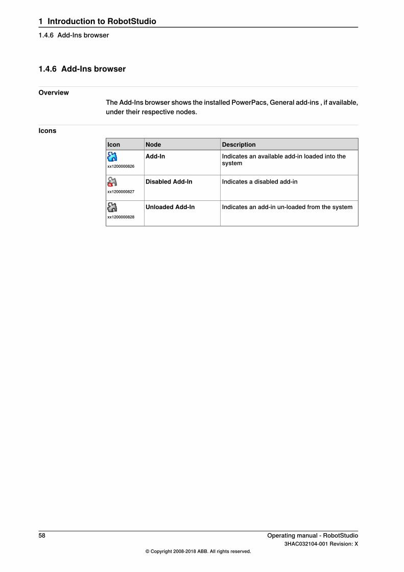
1.4.6 Add-Ins browser
OverviewThe Add-Ins browser shows the installed PowerPacs, General add-ins , if available,under their respective nodes.
Icons
DescriptionNodeIcon
Indicates an available add-in loaded into thesystem
Add-Inxx1200000826
Indicates a disabled add-inDisabled Add-Inxx1200000827
Indicates an add-in un-loaded from the systemUnloaded Add-Inxx1200000828
58 Operating manual - RobotStudio3HAC032104-001 Revision: X
© Copyright 2008-2018 ABB. All rights reserved.
1 Introduction to RobotStudio1.4.6 Add-Ins browser
1.4.7 Windows layout
OverviewRobotStudio has a set of predefined window layouts. These layouts determine thesize and location of the four main windows, Layout, Paths&Targets,Tags andOutput. These windows are enabled by default and can be shown or hidden by theWindows menu.You can access the Windows menu from Customize Quick Access Toolbar >Windows Layout > Windows.
Windows layout optionsThe Windows Layout menu provides the following options:
To..Select this option
Reduce the size of the ribbon.Minimize the Ribbon
Set window layouts to default settings.Default Layout
To enable or disable the window layouts(Layout, Paths&Targets,Tagsand Output).
Windows
Note
The Default Layout option does not work for Windows that RobotStudio Add-Insand PowerPacs add. However, the individual windows can be shown or hiddenby the Windows menu.
Floating WindowAn Operator Window can be undocked by either double-clicking its title bar or byright-clicking the title bar and selecting Float from the menu. An undocked windowis also called a floating window.A floating window can be maximized by either one of the following methods:
• Double-clicking its title bar.• Right-clicking the title bar and selecting Maximize from the menu.• Clicking the maximize button.
Note
A floating window cannot be minimized and will not be displayed in the Windowstaskbar.
A floating window can be docked by either clicking the minimize button or byright-clicking its title bar and selecting Dock from the menu.
Operating manual - RobotStudio 593HAC032104-001 Revision: X
© Copyright 2008-2018 ABB. All rights reserved.
1 Introduction to RobotStudio1.4.7 Windows layout
1.4.8 The Output window
OverviewThe output window displays information about events that occur in the station,such as when simulations are started or stopped. This information is useful whentroubleshooting stations.
Layout of the Output tabThe Output tab contains two columns: the first states the event, the second thetime the message was generated. Each row is a message.
Event typesThe three event types indicate the severity of the event:
DescriptionEvent type
An information message is a normal system event, for example,starting and stopping programs, changing the operationalmode, and turning motors on and off.
Information
Information messages never require an action from you. Theycan be useful for tracking errors, collecting statistics or monit-oring user-triggered event routines.
A warning is an event of which you should be aware, but it isnot so severe that the process or RAPID program needs to bestopped.
Warning
Warnings must occasionally be acknowledged. Warnings oftenindicate underlying problems that at some point will need tobe resolved.
An error is an event that prevents the robot system from pro-ceeding. The running process or RAPID program cannot con-tinue and will be stopped.
Error
An error must occasionally be acknowledged. Some errorsrequire some immediate action from you in order to be resolved.Double-click an error to display a detailed information box.
Some of the events are active. These are linked to an action for resolving theproblem that generated the event. To activate the linked action, double-click themessage.
Handling messages in the Output window
ProcedureGoal
Right-click in the Output window and then click Show mes-sages. From the options All Errors, Information, Warningsand Warnings and Errors, select the type of messages youwant to display.
To filter messages...
Select it, right-click and then click Save to file. Choose a nameand location in the dialog box. Multiple messages can be selec-ted by pressing SHIFT while clicking each.
To save a message to file...
Right-click in the Output window and then click Clear.To clear the Output win-dow...
60 Operating manual - RobotStudio3HAC032104-001 Revision: X
© Copyright 2008-2018 ABB. All rights reserved.
1 Introduction to RobotStudio1.4.8 The Output window

1.4.9 The Controller Status window
OverviewThe Controller Status window shows the operational status of the controllers inyour robot view.
Layout of the Controller Status windowThe Controller Status window has the following columns:
1 System Name : Displays the name of the system running on the controller.2 Controller Name : Displays the name of the controller.3 Controller State : Displays the state of the controller.
the robot is...When the controller is instate...
starting up. It will shift to state motors off when it hasstarted.
Initializing
in a standby state where there is no power to the robot'smotors. The state has to be shifted to motors on beforethe robot can move.
Motors off
ready to move, either by jogging or by running programs.Motors on
stopped because the safety runchain is opened. For in-stance, a door to the robot's cell might be open.
Guard Stop
stopped because emergency stop was activated.Emergency Stop
ready to leave emergency stop state. The emergency stopis no longer activated, but the state transition isn't yetconfirmed.
Waiting for motors onafter e-stop
in a system failure state. Restart required.System Failure
4 Program Execution State : Displays if the robot is running any program ornot.
the robot...When the controller is instate...
is running a program.
Note
A Job will not be executed in this state.
Running
has a program loaded and is ready to run it when a PP(starting point in the program) has been set.
Ready
has a program loaded, with a PP, and is ready to run it.Stopped
has not initialized the program memory. This indicates anerror condition.
Uninitialized
5 Operating Mode : Displays the operating mode of the controller.
the robot is...When the controller isin mode...
starting up. It will shift to the mode selected on the controllerscabinet when it has started.
Initializing
Continues on next pageOperating manual - RobotStudio 613HAC032104-001 Revision: X
© Copyright 2008-2018 ABB. All rights reserved.
1 Introduction to RobotStudio1.4.9 The Controller Status window
the robot is...When the controller isin mode...
ready to run programs in production.AutoIn Auto mode it is possible to get remote Write access to thecontroller, which is necessary for editing programs, config-urations and other things when connected to a real controller.
only able to move if the three-position enabling device onthe FlexPendant is activated. Furthermore, the robot canonly moved with reduced speed in manual mode.
Manual
In manual mode it is not possible to get remote Write accessto the controller, unless it is configured for this and the re-mote Write access granted on the FlexPendant.
only able to move if the three-position enabling device onthe FlexPendant is activated.
Manual full speed
In manual mode it is not possible to get remote Write accessto the controller, unless it is configured for this and the re-mote Write access granted on the FlexPendant.
about to enter Auto mode, but the mode transition has notyet been acknowledged.
Waiting for acknow-ledge
6 Logged on as: Displays the user name the PC is logged on to the controllerwith.
7 Access : Displays the users having write access to the controller, or if it isavailable.
62 Operating manual - RobotStudio3HAC032104-001 Revision: X
© Copyright 2008-2018 ABB. All rights reserved.
1 Introduction to RobotStudio1.4.9 The Controller Status windowContinued
1.4.10 The Operator Window
OverviewOperator Window is an alternative to the corresponding feature in the VirtualFlexPendant for communicating with the user during RAPID program execution.It displays the same output as displayed on the Virtual FlexPendant OperatorWindow.When running in a Virtual Controller, the RAPID program communicates with theoperator via messages on the FlexPendant screen. The Operator Window integratesthis functionality and allows the user to run interactive RAPID programs withoutstarting the Virtual FlexPendant.
Note
The Operator window starts when a Virtual Controller starts. The Virtual Controllerstarts while opening a station or when adding a system.
Enabling Operator WindowTo enable an operator window:
1 On the File menu, click Options.2 On the Navigation pane to the left, select Robotics:Virtual Controller.3 On the Virtual Controller page to the right, selectAutomatically open virtual
Operator Window .4 Click Apply.
Note
When theShow virtual OperatorWindow feature is enabled, an Operator Windowis automatically created for each controller in the station. By default, the windowis located in the tab area below the graphics window.
RAPID InstructionsThe following are the RAPID instructions supported by the Operator Window. Whenthese instructions are executed, the behavior is similar to that of VirtualFlexPendant:
• TPErase• TPReadFK• TPReadNum• TPWrite• UIAlphaEntry• UIMsgBox• UINumEntry
Continues on next pageOperating manual - RobotStudio 633HAC032104-001 Revision: X
© Copyright 2008-2018 ABB. All rights reserved.
1 Introduction to RobotStudio1.4.10 The Operator Window
The following are the RAPID instructions not supported by the Operator Window.When these instructions are executed, an error message is displayed in the OperatorWindow prompting you to use the Virtual Flexpendant instead:
• TPShow• UIShow• UINumTune• UIListView
The controller switches to automatic mode when UIShow is executed.
Note
You should not run both the Virtual Flexpendant and Operator Windowsimultaneously. RobotStudio will automatically request mastership whencommitting data to the controller, when actions are taken in Virtual OperatorWindow. This can cause undesired effect when using the Virtual FlexPendant atthe same time.The emergency stop button pressed on the Virtual FlexPendant cannot be resetthrough the virtual controller control panel. You must resent this button on theVirtual FlexPendant.
64 Operating manual - RobotStudio3HAC032104-001 Revision: X
© Copyright 2008-2018 ABB. All rights reserved.
1 Introduction to RobotStudio1.4.10 The Operator WindowContinued
1.4.11 The Documents window
OverviewThe Documents window allows you to search and browse the RobotStudiodocuments like libraries, geometry and so on in large numbers and from differentlocations. You can also add associate documents with a station, either as a link orby embedding a file in the station.
Opening a Documents window1 On the Home tab, click Import Library and select Documents from the
dropdown menu.The Documents window appears.
Layout of the Documents windowThe Documents window is a docked area that by default takes the right-hand corner.The upper part of the window contains controls for searching and browsing thedocument locations. The lower part consists of a list view that displays thedocuments and folders and a status area.
DescriptionControl
Allows to add documents associated with the station, eitherby adding the file/folder as a reference (link) or by embeddingthe file in the station. See Using the Station mode on page 65.
StationSearch
Allows to search for keywords or query. See Using the Searchmode on page 66.
Search
Displays a folder structure of the document locations. SeeUsing the Browse mode on page 68.
Browse
Allows to configure the document location. See DocumentLocations window on page 70.
Location
Using the Station modeUse this procedure to add documents associated with the current station:
1 Click Station from the Document Manager.2 Click Add button and select what to add to the current station:
• File Reference• Folder Reference• Embedded File• New Text Document
Note
• The referenced file/folder is displayed with an arrow icon• The embedded file and new text document are displayed with a diskette
icon
3 In the Documents window, right-click the document.
Continues on next pageOperating manual - RobotStudio 653HAC032104-001 Revision: X
© Copyright 2008-2018 ABB. All rights reserved.
1 Introduction to RobotStudio1.4.11 The Documents window
The following context menu items appear depending on the document typeselected:
DescriptionItem
Opens the document in the program associated with its filetype. For example, a .docx file is opened in Microsoft Word.
Open
An embedded file is saved to a temporary location beforeopening. If RobotStudio detects that the temporary file haschanged, you will be asked to update the embedded file.
Opens the folder containing the file in Windows Explorer.Open containing folderThis option is not available in embedded files.
Converts a referenced file to an embedded file.Copy to Station
Saves an embedded file to disk.Save as
Specifies if a referenced file/folder should be included whena Pack and Go file is created.
Include in Pack and Go
For a referenced folder, all files in the folder will be included.To use this option, the file must be located in the parentfolder of the station file. For example, if the station file isD:\Documents\Stations\My.rsstn, the reference must belocated in D:\Documents to be included in Pack and Go.Embedded files are always included when a Pack and Gofile is created, since they are part of the station file.
Specifies that subfolders of a referenced folder should beincluded in Pack and Go.
Include Subfolders
Removes the selected document.Remove
Note
Some context menu items can be disabled and the document marked asLocked in the API.
Using the Search mode1 Click the option Search and enter a query or syntax in the text box.
For more information about the available syntaxes, see Search syntax onpage 67.
Note
The drop-down list contains the search history of the previous ten queriesbetween sessions.
2 Click the Expand button to access additional controls.This allows you to specify if the search should cover all the enabled locationsor one specific location.
Continues on next page66 Operating manual - RobotStudio
3HAC032104-001 Revision: X© Copyright 2008-2018 ABB. All rights reserved.
1 Introduction to RobotStudio1.4.11 The Documents windowContinued

3 Select Search in results check box to search for the resulting documents ofthe previous search.
Note
The search is performed automatically, after you stop typing in the textbox or manually, by clicking the glass icon. During the search, this icon ischanged to a cross and clicking this cancels the search operation.
Search syntaxThe search field supports certain keywords and operators which allows you tospecify an advanced search query.
Note
Keywords are not localised.
The following table displays the keywords that specifies an advanced search query:
DescriptionKeywords
matches the filename of the documents.filename
matches the title field of the document metadata.title
matches the type field of the document metadata.typeFor library (.rslib) files, this is a user-defined string. For ex-ample, Robot.For other files, this is the Windows description of the file type.For example, Text Document.
matches the author field of the document metadata.author
matches the comment field of the document metadata.comments
matches the revision field of the document metadata.revision
matches the last time the file was modified.dateFor the colon operator, the match is done against a stringrepresentation of the modified date.For other operators, the search string should interpret as adate according to .NET standards.
matches the file size (in KB).size
used to group or invert queries.and, or, parentheses (), not
The following table displays the operators that specifies an advanced search query
DescriptionOperator
matches if the field contains the search string.:
matches if the field equals the search string.=
matches if the field is smaller than the search string.<
matches if the field is greater than the search string.>
Continues on next pageOperating manual - RobotStudio 673HAC032104-001 Revision: X
© Copyright 2008-2018 ABB. All rights reserved.
1 Introduction to RobotStudio1.4.11 The Documents window
Continued

Note
• Quotation marks can be used to specify a string with whitespace. An emptystring is specified by "".
• All search strings are case insensitive.• Text without a preceding keyword is matched against the filename and all
metadata.• If queries are specified without a grouping keyword, "and" is implied.• Some metadata (title, author, comments and revision) is not available for
all file types.
Examples• 1400 - Matches documents with the string 1400 in the filename or any
metadata.• not author:ABB - Matches documents where the author field does not contain
the string ABB.• size>1000 and date<1/2009 - Matches documents larger than 1000KB and
modified before 1/1/2009.• IRBP comments="ABB Internal" - Matches documents with the string IRBP
in the filename or any metadata, and where the comment field equals ABBInternal.
Using the Browse mode1 Click the option Browse from the Document Manager.
A folder structure of the document location is displayed.
Note
The top level of the folder structure lists the configured locations. If alocation is unavailable (for example, an offline network path) it is markedas Unavailable and cannot be opened. The text box displays the path ofthe current folder relative to the location root.
2 You can open a folder in either of the two ways:• Double-click the document location.• Right-click the document location and select Open from the context
menu.3 You can navigate through the folders in either of the two ways:
• Click the folder icon at the top-right corner.• Select the parent folder from the dropdown list.
Note
You can browse and add component xml files (*.rsxml) to your station.
Continues on next page68 Operating manual - RobotStudio
3HAC032104-001 Revision: X© Copyright 2008-2018 ABB. All rights reserved.
1 Introduction to RobotStudio1.4.11 The Documents windowContinued

4 Click Refresh icon in the text box to manually refresh the contents of thefolder.
Note
The refresh operation can be time consuming, if a folder resides in anetwork location or contains many documents. During this time, the refreshicon changes to a cross icon allowing you to cancel the operation.
Results viewIn the Browse mode, items are grouped into folders and documents. The resultingfolders and documents are displayed in a list view.The search result appears in the status bar at the bottom, displaying the numberof items found, and progress made during the search. The Search results aregrouped beneath headers according to their location.Each document is represented by an image, the document title or filename in blacktext, and the metadata and file information in grey text. For library files, the imagecan be a screenshot or other custom image. For other document types, the imageis the icon associated with the file type.
Using the Context menuIn the results view, right-click a document or folder. The following context menuitems appears:
DescriptionItem
This command opens the selected folder, library or geometryfiles, station files, and document.
• For folders, browses into the selected folder.• For library or geometry files, imports the file into the
station. (If no station is open ,a new empty station is firstcreated.)
• For station files, opens the station.• For other documents, attempts to open the selected
document according to its file association. For example,Microsoft Word starts when a .doc file is opened.
Open
This command opens the folder containing the document orthe folder in the Windows Explorer.
Open containing folder
This command is disabled for folders.PropertiesThis command opens a dialog that displays complete metadataand file information about the selected document.
Tip
Double-click an item to import the library and geometry files and open the otherdocuments.
Continues on next pageOperating manual - RobotStudio 693HAC032104-001 Revision: X
© Copyright 2008-2018 ABB. All rights reserved.
1 Introduction to RobotStudio1.4.11 The Documents window
Continued
In the results view, right-click an empty area. The following context menu appearsthat controls how the documents are grouped and sorted:
DescriptionItems
Controls how the documents are arranged in groups.Group by:The following options are available:
• Location• Folder• Type
Controls how the documents are sorted within the group.Sort by:The following options are available:
• Name• Date• Size
Items are sorted in the ascending and descending order.Ascending and Descending
Using the drag and drop featureYou can import a library or a geometry file into the station by dragging it from theresults view into either the graphics window, or onto an object node in the Layoutbrowser.
• When dragging into the Layout browser, the component will be placed as achild object under the station, component group or smart component.
• When dragging into the graphics window, the component will be positionedat the point on the station floor where you drop it. You can snap the point tothe UCS grid by enabling the Snap Grid or by holding down the ALT keywhile dragging.
Document Locations windowYou can launch the Document Locations window in any one of the following ways:
1 Select Locations from the Documents window.2 On the File menu, click Options and select Files & Folders in the navigation
pane. Click Document Locations on the right side.3 On the Home tab, click Import Library and select Locations from the
dropdown menu.
Layout of the Document Locations windowIt consists of a menu bar and a list displaying the configured locations. The listdisplays general information about the locations. The menu bar contains thefollowing controls:
DescriptionControls
The following options are available from the dropdown menu:• Import : Opens a dialog box to import document loca-
tions from an xml file. If a location with the same URLalready exists, you have the option to retain or deletethe existing location.
• Export : Opens a dialog box to export all the configuredlocations to an xml file.
• Reset to Default : Loads the default locations (ABBLibrary, User Library, and User Geometry).
Locations
Continues on next page70 Operating manual - RobotStudio
3HAC032104-001 Revision: X© Copyright 2008-2018 ABB. All rights reserved.
1 Introduction to RobotStudio1.4.11 The Documents windowContinued

DescriptionControls
Opens a dialog box to add a document location. By default,there is one location type available.
Add Location
For more information, see File System location on page 71.
Deletes the selected location.Remove
Opens a dialog box to modify the selected location. For moreinformation, see File System location on page 71.
Edit
File System location1 Click Add Locations and select File System from the dropdown menu. The
File System dialog box appears.The File System dialog box contains the following controls:
DescriptionControl
Specifies a name associated with the location.Location Name
Specifies the file system directory that corresponds to the rootfolder of the location. This can be on a local or network disk.
Path
Specifies a filename filter to include only certain files whensearching and browsing. Multiple filters are separated by asemicolon. If the filter is empty all files are included.
Filter
Specifies that the library and geometry files from a networklocation should be copied to a local directory and importedfrom there, rather than directly from the network path.
Cache files from network
This will ensure that a station containing such files can beopened even if the network location is unavailable. This optionis only available for network locations.
Specifies the directory where to store the local copies. Thismust be on a local disk.
Directory
Specifies that the contents of the location should be displayedas a gallery in the specified ribbon menu.
Show as gallery
• Flat - Specifies that all documents are displayed in asingle gallery with subfolder names as headers.
• Recursive - Specifies that the documents are displayedin submenus corresponding to the folder structure.
Style
Specifies if the search should cover all the enabled locations.Include when searching alllocations
Select this check box to define a custom location for packages.You can access this package from the RobotApps window inthe section as named in the Location Name box.
Note
You must close and re-open the RobotApps window for thechanges to happen.
Package (.rspak) installa-tion source
Operating manual - RobotStudio 713HAC032104-001 Revision: X
© Copyright 2008-2018 ABB. All rights reserved.
1 Introduction to RobotStudio1.4.11 The Documents window
Continued
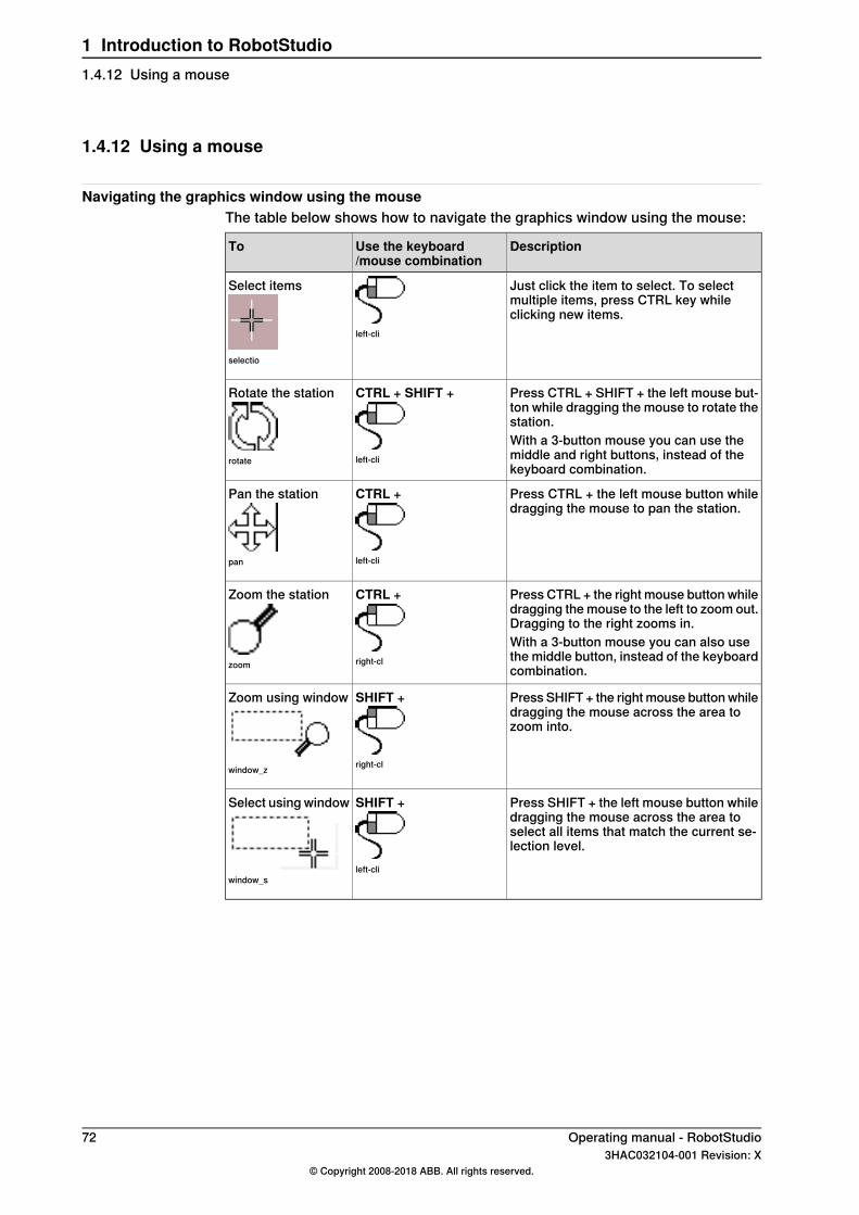
1.4.12 Using a mouse
Navigating the graphics window using the mouseThe table below shows how to navigate the graphics window using the mouse:
DescriptionUse the keyboard/mouse combination
To
Just click the item to select. To selectmultiple items, press CTRL key whileclicking new items.
left-cli
Select items
selectio
Press CTRL + SHIFT + the left mouse but-ton while dragging the mouse to rotate thestation.
CTRL + SHIFT +
left-cli
Rotate the station
rotate
With a 3-button mouse you can use themiddle and right buttons, instead of thekeyboard combination.
Press CTRL + the left mouse button whiledragging the mouse to pan the station.
CTRL +
left-cli
Pan the station
pan
Press CTRL + the right mouse button whiledragging the mouse to the left to zoom out.Dragging to the right zooms in.
CTRL +
right-cl
Zoom the station
zoom
With a 3-button mouse you can also usethe middle button, instead of the keyboardcombination.
Press SHIFT + the right mouse button whiledragging the mouse across the area tozoom into.
SHIFT +
right-cl
Zoom using window
window_z
Press SHIFT + the left mouse button whiledragging the mouse across the area toselect all items that match the current se-lection level.
SHIFT +
left-cli
Select using window
window_s
72 Operating manual - RobotStudio3HAC032104-001 Revision: X
© Copyright 2008-2018 ABB. All rights reserved.
1 Introduction to RobotStudio1.4.12 Using a mouse
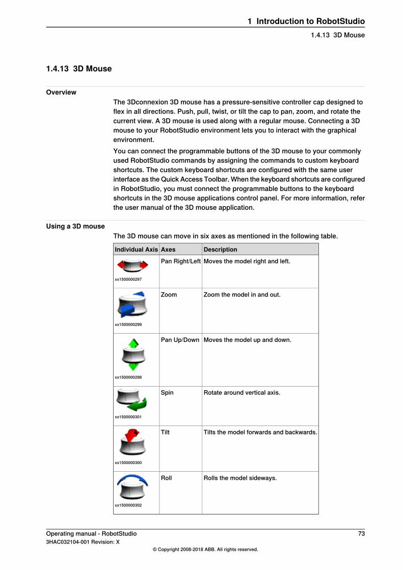
1.4.13 3D Mouse
OverviewThe 3Dconnexion 3D mouse has a pressure-sensitive controller cap designed toflex in all directions. Push, pull, twist, or tilt the cap to pan, zoom, and rotate thecurrent view. A 3D mouse is used along with a regular mouse. Connecting a 3Dmouse to your RobotStudio environment lets you to interact with the graphicalenvironment.You can connect the programmable buttons of the 3D mouse to your commonlyused RobotStudio commands by assigning the commands to custom keyboardshortcuts. The custom keyboard shortcuts are configured with the same userinterface as the Quick Access Toolbar. When the keyboard shortcuts are configuredin RobotStudio, you must connect the programmable buttons to the keyboardshortcuts in the 3D mouse applications control panel. For more information, referthe user manual of the 3D mouse application.
Using a 3D mouseThe 3D mouse can move in six axes as mentioned in the following table.
DescriptionAxesIndividual Axis
Moves the model right and left.Pan Right/Left
xx1500000297
Zoom the model in and out.Zoom
xx1500000299
Moves the model up and down.Pan Up/Down
xx1500000298
Rotate around vertical axis.Spin
xx1500000301
Tilts the model forwards and backwards.Tilt
xx1500000300
Rolls the model sideways.Roll
xx1500000302
Operating manual - RobotStudio 733HAC032104-001 Revision: X
© Copyright 2008-2018 ABB. All rights reserved.
1 Introduction to RobotStudio1.4.13 3D Mouse
1.4.14 Selecting an item
OverviewEach item in a station can be moved to achieve the required layout, so you firsthave to determine its selection level. The selection level makes it possible to selectonly specific types of items, or specified parts of objects.The selection levels are curve, surface, entity, part, mechanism, group, target/frameand path. The target/frame and path selection can be combined with any of theother selection levels.Objects may also be grouped together as component groups, see ComponentGroup on page 286.
Selecting an item in the graphics windowTo select items in the graphics window, follow these steps:
1 At the top of the graphics window, click the desired selection level icon.2 Optionally, click the desired snap mode icon for the part of the item you wish
to select.3 In the graphics window, click the item. The selected item will be highlighted.
Multiple selection of items in the graphics windowTo select multiple items in the graphics window, do the following:
1 Press the SHIFT key, and in the graphics window drag the mouse diagonallyover the objects to select.
Selecting an item in the browsersTo select items in a browser, do the following:
1 Click the item. The selected item will be highlighted in the browser.
Multiple selection of items in the browsersTo select multiple items in a browser, follow these steps:
1 Make sure that all the items to be selected are of the same type and locatedin the same branch of the hierarchical structure; otherwise, the items will notbe operable.
2 Do one of the following:• To select adjacent items: In the browser, hold down the SHIFT key and
click the first and then the last item. The list of items will be highlighted.• To select separate items: In the browser, hold down the CTRL key and
click the items you want to select. The items will be highlighted.
74 Operating manual - RobotStudio3HAC032104-001 Revision: X
© Copyright 2008-2018 ABB. All rights reserved.
1 Introduction to RobotStudio1.4.14 Selecting an item
1.4.15 Attaching and detaching objects
OverviewYou can attach an object (child) to another object (parent). Attachments can becreated on part level and on mechanism level. When an object has been attachedto a parent, moving the parent also moves the child.One of the most common attachments is to attach a tool to a robot. For procedures,see Attach to on page 496 and Detach on page 503.
Operating manual - RobotStudio 753HAC032104-001 Revision: X
© Copyright 2008-2018 ABB. All rights reserved.
1 Introduction to RobotStudio1.4.15 Attaching and detaching objects

1.4.16 Keyboard shortcuts
General keyboard shortcutsThe following table lists general keyboard shortcuts in RobotStudio.
Key CombinationCommand
General Shortcuts
F10Activate menu bar
ALT + F1Open API Help
F1Open Help
CTRL + F5Open Virtual FlexPendant
CTRL + TABSwitch between windows
General Commands
F4Add Controller System
CTRL + OOpen Station
CTRL + BTake Screenshot
CTRL + SHIFT + RTeach Instruction
CTRL + RTeach Target
CTRL + GImport Geometry
CTRL + JImport Library
CTRL + NNew Empty Station
CTRL + SSave Station
Arrow keysRotate the station
PgUp and PgDnZoom the station
CTRL + arrow keysPan the station
General Editing Commands
CTRL + CCopy
CTRL + XCut
CTRL + VPaste
DELETEDelete
CTRL + YRedo
F5Refresh
F2Rename
CTRL + ASelect All
Ctrl+Shift+SSave All
CTRL + ZUndo
Continues on next page76 Operating manual - RobotStudio
3HAC032104-001 Revision: X© Copyright 2008-2018 ABB. All rights reserved.
1 Introduction to RobotStudio1.4.16 Keyboard shortcuts
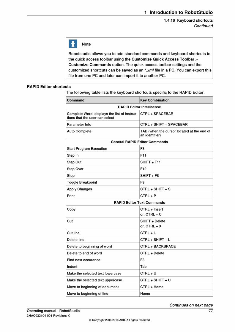
Note
Robotstudio allows you to add standard commands and keyboard shortcuts tothe quick access toolbar using the Customize Quick Access Toolbar >Customize Commands option. The quick access toolbar settings and thecustomized shortcuts can be saved as an *.xml file in a PC. You can export thisfile from one PC and later can import it to another PC.
RAPID Editor shortcutsThe following table lists the keyboard shortcuts specific to the RAPID Editor.
Key CombinationCommand
RAPID Editor Intellisense
CTRL + SPACEBARComplete Word, displays the list of instruc-tions that the user can select
CTRL + SHIFT + SPACEBARParameter Info
TAB (when the cursor located at the end ofan identifier)
Auto Complete
General RAPID Editor Commands
F8Start Program Execution
F11Step In
SHIFT + F11Step Out
F12Step Over
SHIFT + F8Stop
F9Toggle Breakpoint
CTRL + SHIFT + SApply Changes
CTRL + PPrint
RAPID Editor Text Commands
CTRL + InsertCopyor, CTRL + C
SHIFT + DeleteCutor, CTRL + X
CTRL + LCut line
CTRL + SHIFT + LDelete line
CTRL + BACKSPACEDelete to beginning of word
CTRL + DeleteDelete to end of word
F3Find next occurance
TabIndent
CTRL + UMake the selected text lowercase
CTRL + SHIFT + UMake the selected text uppercase
CTRL + HomeMove to beginning of document
HomeMove to beginning of line
Continues on next pageOperating manual - RobotStudio 773HAC032104-001 Revision: X
© Copyright 2008-2018 ABB. All rights reserved.
1 Introduction to RobotStudio1.4.16 Keyboard shortcuts
Continued
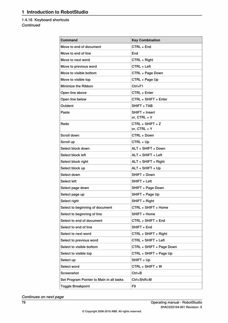
Key CombinationCommand
CTRL + EndMove to end of document
EndMove to end of line
CTRL + RightMove to next word
CTRL + LeftMove to previous word
CTRL + Page DownMove to visible bottom
CTRL + Page UpMove to visible top
Ctrl+F1Minimize the Ribbon
CTRL + EnterOpen line above
CTRL + SHIFT + EnterOpen line below
SHIFT + TABOutdent
SHIFT + InsertPasteor, CTRL + V
CTRL + SHIFT + ZRedoor, CTRL + Y
CTRL + DownScroll down
CTRL + UpScroll up
ALT + SHIFT + DownSelect block down
ALT + SHIFT + LeftSelect block left
ALT + SHIFT + RightSelect block right
ALT + SHIFT + UpSelect block up
SHIFT + DownSelect down
SHIFT + LeftSelect left
SHIFT + Page DownSelect page down
SHIFT + Page UpSelect page up
SHIFT + RightSelect right
CTRL + SHIFT + HomeSelect to beginning of document
SHIFT + HomeSelect to beginning of line
CTRL + SHIFT + EndSelect to end of document
SHIFT + EndSelect to end of line
CTRL + SHIFT + RightSelect to next word
CTRL + SHIFT + LeftSelect to previous word
CTRL + SHIFT + Page DownSelect to visible bottom
CTRL + SHIFT + Page UpSelect to visible top
SHIFT + UpSelect up
CTRL + SHIFT + WSelect word
Ctrl+BScreenshot
Ctrl+Shift+MSet Program Pointer to Main in all tasks
F9Toggle Breakpoint
Continues on next page78 Operating manual - RobotStudio
3HAC032104-001 Revision: X© Copyright 2008-2018 ABB. All rights reserved.
1 Introduction to RobotStudio1.4.16 Keyboard shortcutsContinued
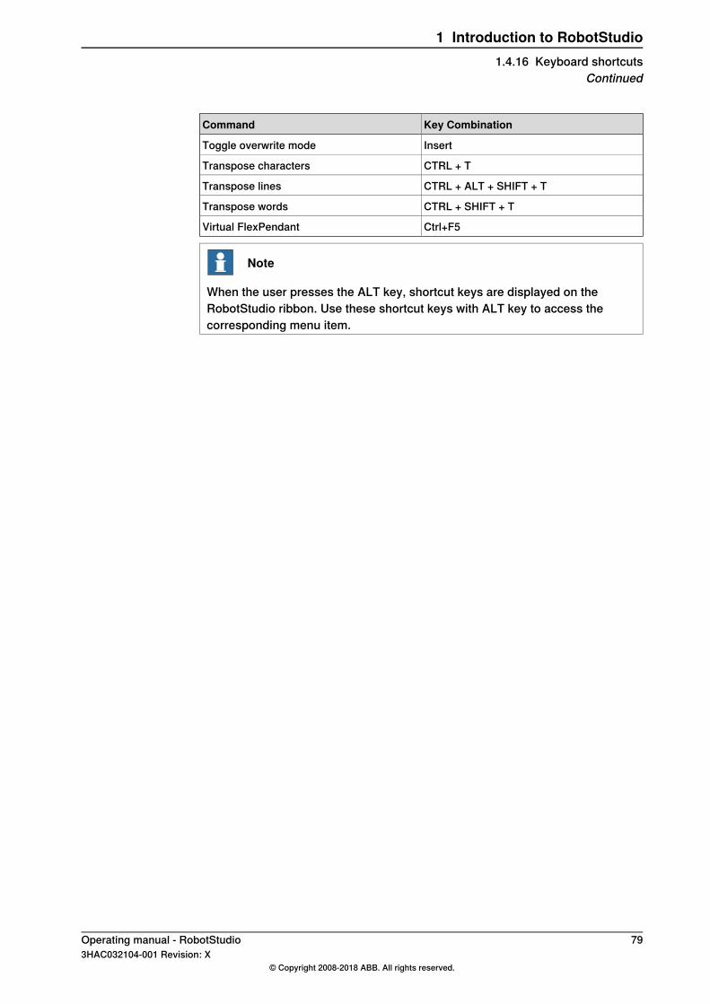
Key CombinationCommand
InsertToggle overwrite mode
CTRL + TTranspose characters
CTRL + ALT + SHIFT + TTranspose lines
CTRL + SHIFT + TTranspose words
Ctrl+F5Virtual FlexPendant
Note
When the user presses the ALT key, shortcut keys are displayed on theRobotStudio ribbon. Use these shortcut keys with ALT key to access thecorresponding menu item.
Operating manual - RobotStudio 793HAC032104-001 Revision: X
© Copyright 2008-2018 ABB. All rights reserved.
1 Introduction to RobotStudio1.4.16 Keyboard shortcuts
Continued

This page is intentionally left blank
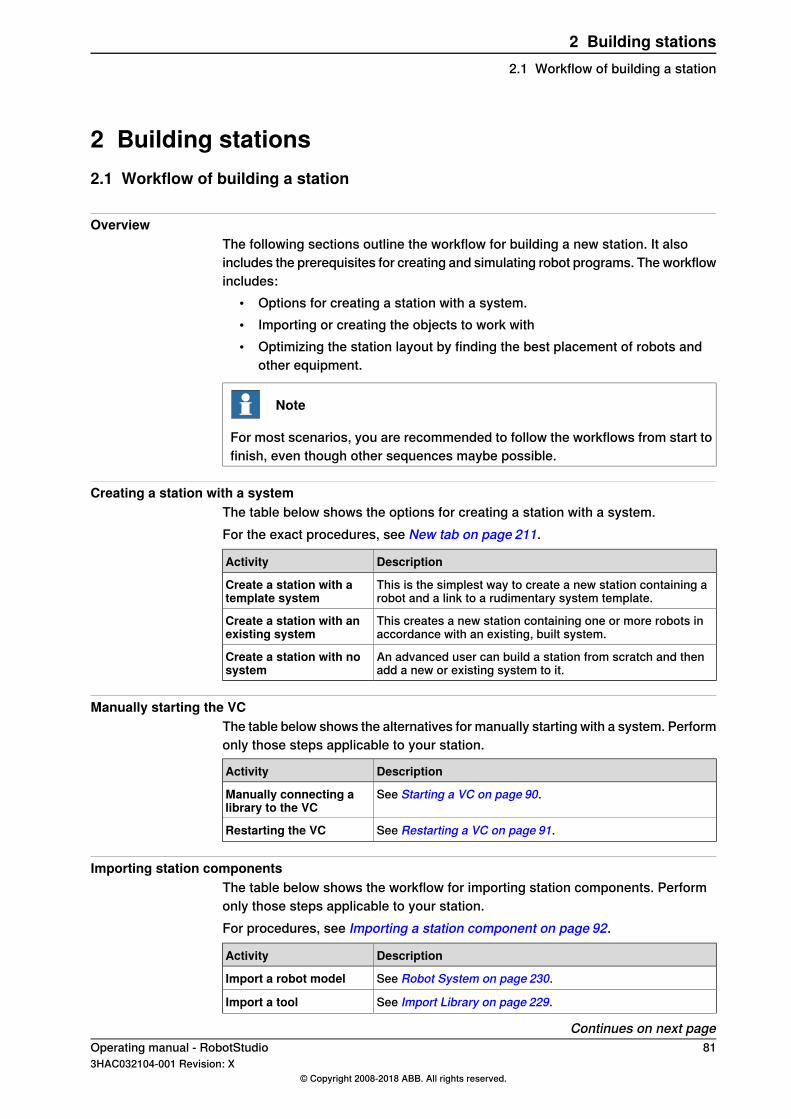
2 Building stations2.1 Workflow of building a station
OverviewThe following sections outline the workflow for building a new station. It alsoincludes the prerequisites for creating and simulating robot programs. The workflowincludes:
• Options for creating a station with a system.• Importing or creating the objects to work with• Optimizing the station layout by finding the best placement of robots and
other equipment.
Note
For most scenarios, you are recommended to follow the workflows from start tofinish, even though other sequences maybe possible.
Creating a station with a systemThe table below shows the options for creating a station with a system.For the exact procedures, see New tab on page 211.
DescriptionActivity
This is the simplest way to create a new station containing arobot and a link to a rudimentary system template.
Create a station with atemplate system
This creates a new station containing one or more robots inaccordance with an existing, built system.
Create a station with anexisting system
An advanced user can build a station from scratch and thenadd a new or existing system to it.
Create a station with nosystem
Manually starting the VCThe table below shows the alternatives for manually starting with a system. Performonly those steps applicable to your station.
DescriptionActivity
See Starting a VC on page 90.Manually connecting alibrary to the VC
See Restarting a VC on page 91.Restarting the VC
Importing station componentsThe table below shows the workflow for importing station components. Performonly those steps applicable to your station.For procedures, see Importing a station component on page 92.
DescriptionActivity
See Robot System on page 230.Import a robot model
See Import Library on page 229.Import a tool
Continues on next pageOperating manual - RobotStudio 813HAC032104-001 Revision: X
© Copyright 2008-2018 ABB. All rights reserved.
2 Building stations2.1 Workflow of building a station
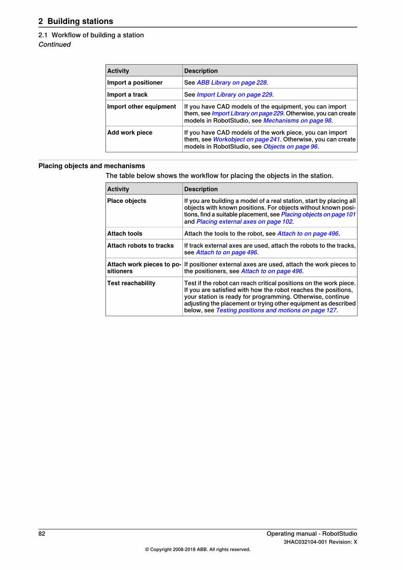
DescriptionActivity
See ABB Library on page 228.Import a positioner
See Import Library on page 229.Import a track
If you have CAD models of the equipment, you can importthem, see Import Library on page229. Otherwise, you can createmodels in RobotStudio, see Mechanisms on page 98.
Import other equipment
If you have CAD models of the work piece, you can importthem, see Workobject on page 241. Otherwise, you can createmodels in RobotStudio, see Objects on page 96.
Add work piece
Placing objects and mechanismsThe table below shows the workflow for placing the objects in the station.
DescriptionActivity
If you are building a model of a real station, start by placing allobjects with known positions. For objects without known posi-tions, find a suitable placement, seePlacing objects on page101and Placing external axes on page 102.
Place objects
Attach the tools to the robot, see Attach to on page 496.Attach tools
If track external axes are used, attach the robots to the tracks,see Attach to on page 496.
Attach robots to tracks
If positioner external axes are used, attach the work pieces tothe positioners, see Attach to on page 496.
Attach work pieces to po-sitioners
Test if the robot can reach critical positions on the work piece.If you are satisfied with how the robot reaches the positions,your station is ready for programming. Otherwise, continueadjusting the placement or trying other equipment as describedbelow, see Testing positions and motions on page 127.
Test reachability
82 Operating manual - RobotStudio3HAC032104-001 Revision: X
© Copyright 2008-2018 ABB. All rights reserved.
2 Building stations2.1 Workflow of building a stationContinued
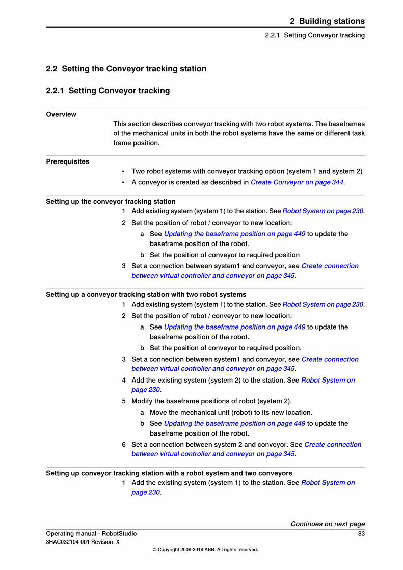
2.2 Setting the Conveyor tracking station
2.2.1 Setting Conveyor tracking
OverviewThis section describes conveyor tracking with two robot systems. The baseframesof the mechanical units in both the robot systems have the same or different taskframe position.
Prerequisites• Two robot systems with conveyor tracking option (system 1 and system 2)• A conveyor is created as described in Create Conveyor on page 344.
Setting up the conveyor tracking station1 Add existing system (system 1) to the station. SeeRobot System on page230.2 Set the position of robot / conveyor to new location:
a See Updating the baseframe position on page 449 to update thebaseframe position of the robot.
b Set the position of conveyor to required position3 Set a connection between system1 and conveyor, see Create connection
between virtual controller and conveyor on page 345.
Setting up a conveyor tracking station with two robot systems1 Add existing system (system 1) to the station. SeeRobot System on page230.2 Set the position of robot / conveyor to new location:
a See Updating the baseframe position on page 449 to update thebaseframe position of the robot.
b Set the position of conveyor to required position.3 Set a connection between system1 and conveyor, see Create connection
between virtual controller and conveyor on page 345.4 Add the existing system (system 2) to the station. See Robot System on
page 230.5 Modify the baseframe positions of robot (system 2).
a Move the mechanical unit (robot) to its new location.b See Updating the baseframe position on page 449 to update the
baseframe position of the robot.6 Set a connection between system 2 and conveyor. See Create connection
between virtual controller and conveyor on page 345.
Setting up conveyor tracking station with a robot system and two conveyors1 Add the existing system (system 1) to the station. See Robot System on
page 230.
Continues on next pageOperating manual - RobotStudio 833HAC032104-001 Revision: X
© Copyright 2008-2018 ABB. All rights reserved.
2 Building stations2.2.1 Setting Conveyor tracking
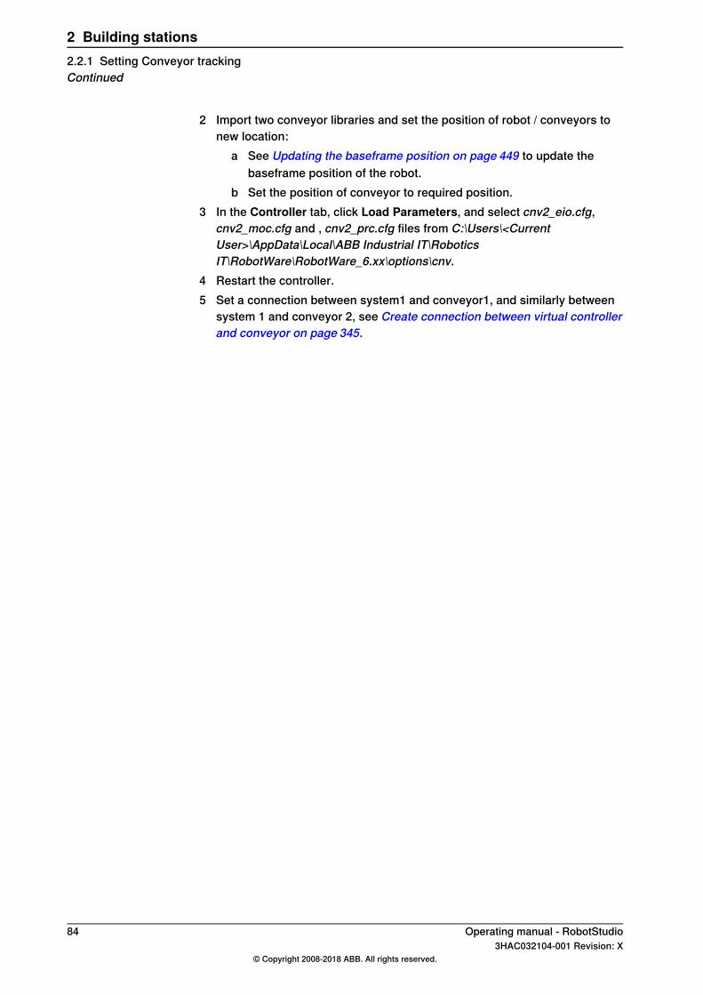
2 Import two conveyor libraries and set the position of robot / conveyors tonew location:
a See Updating the baseframe position on page 449 to update thebaseframe position of the robot.
b Set the position of conveyor to required position.3 In the Controller tab, click Load Parameters, and select cnv2_eio.cfg,
cnv2_moc.cfg and , cnv2_prc.cfg files from C:\Users\<CurrentUser>\AppData\Local\ABB Industrial IT\RoboticsIT\RobotWare\RobotWare_6.xx\options\cnv.
4 Restart the controller.5 Set a connection between system1 and conveyor1, and similarly between
system 1 and conveyor 2, see Create connection between virtual controllerand conveyor on page 345.
84 Operating manual - RobotStudio3HAC032104-001 Revision: X
© Copyright 2008-2018 ABB. All rights reserved.
2 Building stations2.2.1 Setting Conveyor trackingContinued

2.3 Creating a system with external axes automatically
Automatically create a system with external axes1 Import the desired robots, positioners, and track libraries into the RobotStudio
station. See Import Library on page 229.If a robot and track are selected, attach the robot to the track. See Attach toon page 496.
2 Create a robot system from layout. See Robot System on page 230.
Note
To create a robot system with IRBT4004, IRBT6004, or IRBT7004, theTrackMotion mediapool Type A must be installed. For more information,see Installing and licensing RobotStudio on page 44.
Supported external axes configurations for RobotWare 5The following table shows a combination of different external axes configurations:
Positioner typeCombination
R2xLLKDCBA
YYYYYYYYOne IRB (Positioner in sametask)
YYYYYYYYOne IRB (Positioner in sep-arate task)
YNYYYYYYTwo IRB (Positioner in sep-arate task)
NYYYXNNNYOne IRB on Track Motion(Positioner in same task)
NYNNNNNNOne IRB on Track Motion(Positioner in separate task)
• Y - Combination is supported• N - Combination is not supported• YX - Combination is supported and manual mapping of mechanical units and
joints required
Note
Creating a system from layout only supports tracks of type RTT and IRBTx003in combination with positioners. i.e. IRBTx004 is not supported in combinationwith the positioners.
Continues on next pageOperating manual - RobotStudio 853HAC032104-001 Revision: X
© Copyright 2008-2018 ABB. All rights reserved.
2 Building stations2.3 Creating a system with external axes automatically
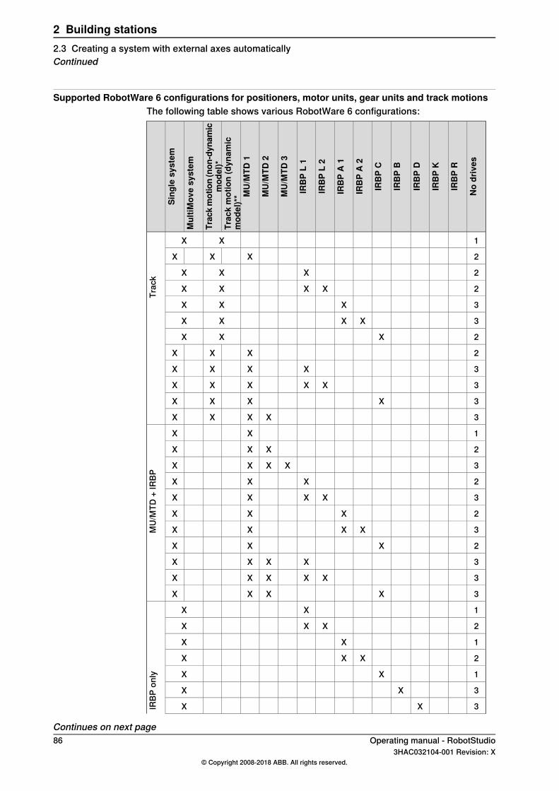
Supported RobotWare 6 configurations for positioners, motor units, gear units and track motionsThe following table shows various RobotWare 6 configurations:
Nodrives
IRBP
R
IRBP
K
IRBP
D
IRBP
B
IRBP
C
IRBP
A2
IRBP
A1
IRBP
L2
IRBP
L1
MU/MTD
3
MU/MTD
2
MU/MTD
1
Trackmotion(dynam
icmod
el)**
Trackmotion(non
-dynam
icmod
el)*
MultiM
ovesystem
Sing
lesystem
1XX
Trac
k
2XXX
2XXX
2XXXX
3XXX
3XXXX
2XXX
2XXX
3XXXX
3XXXXX
3XXXX
3XXXX
1XX
MU/
MTD
+IR
BP
2XXX
3XXXX
2XXX
3XXXX
2XXX
3XXXX
2XXX
3XXXX
3XXXXX
3XXXX
1XX
IRBP
only
2XXX
1XX
2XXX
1XX
3XX
3XX
Continues on next page86 Operating manual - RobotStudio
3HAC032104-001 Revision: X© Copyright 2008-2018 ABB. All rights reserved.
2 Building stations2.3 Creating a system with external axes automaticallyContinued
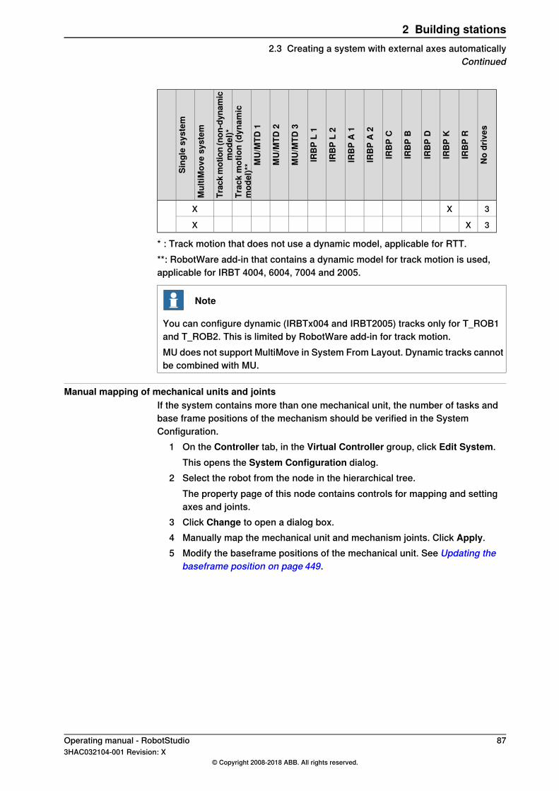
Nodrives
IRBP
R
IRBP
K
IRBP
D
IRBP
B
IRBP
C
IRBP
A2
IRBP
A1
IRBP
L2
IRBP
L1
MU/MTD
3
MU/MTD
2
MU/MTD
1
Trackmotion(dynam
icmod
el)**
Trackmotion(non
-dynam
icmod
el)*
MultiM
ovesystem
Sing
lesystem
3XX
3XX
* : Track motion that does not use a dynamic model, applicable for RTT.**: RobotWare add-in that contains a dynamic model for track motion is used,applicable for IRBT 4004, 6004, 7004 and 2005.
Note
You can configure dynamic (IRBTx004 and IRBT2005) tracks only for T_ROB1and T_ROB2. This is limited by RobotWare add-in for track motion.MU does not support MultiMove in System From Layout. Dynamic tracks cannotbe combined with MU.
Manual mapping of mechanical units and jointsIf the system contains more than one mechanical unit, the number of tasks andbase frame positions of the mechanism should be verified in the SystemConfiguration.
1 On the Controller tab, in the Virtual Controller group, click Edit System.This opens the System Configuration dialog.
2 Select the robot from the node in the hierarchical tree.The property page of this node contains controls for mapping and settingaxes and joints.
3 Click Change to open a dialog box.4 Manually map the mechanical unit and mechanism joints. Click Apply.5 Modify the baseframe positions of the mechanical unit. See Updating the
baseframe position on page 449.
Operating manual - RobotStudio 873HAC032104-001 Revision: X
© Copyright 2008-2018 ABB. All rights reserved.
2 Building stations2.3 Creating a system with external axes automatically
Continued
2.4 Manually setting up system based on RobotWare 5.xx with track motion
2.4.1 Track motion of type RTT or IRBTx003
Manually setting up a system with track motion of type RTT or IRBTx003Use this procedure to manually set up a system with track motion type RTT Bobin,RTT Marathon or IRBT4003, IRBT6003, or IRBT7003.
1 Build and start a new system. See Building a new system on page 165.
DescriptionAction
In the New Controller System wizard of theInstallation Manager, naviagte to Modify Op-tions page and scroll down to Drive Module1 > Drive module application group and ex-pand ABB Standard manipulator option andselect Manipulator type (IRB6600).
Select the desired robot variant(IRB6600).
1
In the New Controller System wizard of theInstallation Manager, naviagte to Modify Op-tions page of the Installation Manager, scrolldown to Drive Module 1> Additional axesconfiguration group and expand theAdd axesIRB/drive module 6600 option and select the770-4 Drive W in pos Y2 option.
Select the Additional axes config-uration.
2
The option 770-4 Drive W in pos Y2, the Drivemodule, and the Position varies dependingon theAdditional axes configuration selected.Make sure to select at least one drive in anyposition.
Close the Modify Options page.Click Finish.3
2 Add the system to the station. See Adding a system on page 903 Add the corresponding track configuration file of the desired robot variant
(IRB 6600) and the desired track model to the station. See Adding the trackto the system on page 92.
Note
In the Select Library group, select either the existing track or import adifferent track.The system may fail unless the correct additional axes configuration isselected.
4 Specify whether the baseframe is moved by another mechanism.a On theController tab, in theVirtual Controller group, clickEdit System.
This opens the System Configuration dialog.b Select ROB_1 node from the hierarchical tree.c Select the option Track from the BaseFrame moved by list.d Click OK. When asked if you want to restart the system, answer Yes.
Close the System Configuration window.
88 Operating manual - RobotStudio3HAC032104-001 Revision: X
© Copyright 2008-2018 ABB. All rights reserved.
2 Building stations2.4.1 Track motion of type RTT or IRBTx003

2.4.2 Track motion of type IRBTx004
OverviewFor configuration of tracks of type IRBT4004, IRBT6004, or IRBT7004, theTrackMotion mediapool must be installed. For more information, see Installing andlicensing RobotStudio on page 44.
Manually setting up a system with track motion of type IRBTx0041 Build and start a new system. See Building a new system on page 165.
DescriptionAction
See Adding additional options on page 166.Add add-ins for IRBTx004.1Browse and select the key file (.kxt) locatedin the mediapool Track 5.XX.YYYYwhere 5.XXindicates the latest RobotWare version beingused.
On the Modify Options page of the Installa-tion Manager, scroll down to Drive Module 1> Drivemodule application group and expandABBStandardmanipulator option and selectManipulator type (IRB6600).
Select the desired robot variant(IRB6600).
2
On the Modify Options page of the Installa-tion Manager, scroll down to Drive Module1> Additional axes configuratin group andexpand the Add axes IRB/drive module 6600option and select the 770-4 DriveW in pos Y2option.
SelectAdditional axes configur-ation.
3
The option 770-4 DriveW in pos Y2, theDrivemodule, and the Position varies dependingon the Additional axes configuration selec-ted. Make sure to select at least one drive inany position.
On the Modify Options page of the Installa-tion Manager, scroll down to the TRACK andexpand the Drive module for Track motiongroup. Select Drive Module 1 >Track Motiontype >IRBT 6004 > Irb Orientation on Track> Standard carriage In Line > Select TrackMotion Length > 1.7m (or any other variant).
Select the desired track motion(IRBT 6004).
4
Close the Modify Options page.Click Finish.5
2 Add the system to the station. See Adding a system on page 90.3 Add the desired track model to the station using the following procedure.
See Adding the track to the system on page 92.a In the Select Library group, click Other to import a different track
motion library.b Click OK. When asked if you want to restart the system, answer Yes.
Close the System Configuration window.
Operating manual - RobotStudio 893HAC032104-001 Revision: X
© Copyright 2008-2018 ABB. All rights reserved.
2 Building stations2.4.2 Track motion of type IRBTx004
2.5 Virtual controller
2.5.1 Starting a VC
OverviewRobotStudio uses virtual controllers for running the robots. Virtual controllers canrun both systems for real robots and specific virtual systems for testing andevaluation purposes. A virtual controller uses the same software as the controllerto execute the RAPID program, to calculate robot motions and to handle I/O signals.When starting a virtual controller, point out which system to run on it. Since thesystem contains information about the robots to use and important data such asrobot programs and configurations, it is important to select the right system forthe station.
Note
You can start and stop a virtual controller, using a given system path and withoutneeding a station. For more information, see Start Virtual Controller on page387.
Starting a VCThe table below describes the different ways a virtual controller may start:
DescriptionStartup
In most cases, a VC is automatically started when you createa new station. Library files for the robots used by the systemare then imported to the station.
Automatic, when creatinga station
If your station uses several systems or if you started with anempty station, you can add systems to an open station. Libraryfiles for the robots used by the the systems are then importedto the station.
Automatic, when adding asystem to an existing sta-tion
If you have manually imported a robot library you want to usewith a system, instead of importing a new library at startup,you can connect this library to a controller.
Manually, when connectingto an imported library
If you have manually imported a robot library you want to usewith a system, instead of importing a new library at startup,you can connect this library to a controller.A library may only be connected to a single-robot system andmay not be already connected to another VC.
The Start Virtual Controller commands allows you start andstop a virtual controller, using a given system path and withoutneeding a station.
Manually, when starting acontroller from the Control-ler tab.
Adding a systemTo add a system to a new station, see New tab on page 211.To add a system to an existing station, see Robot System on page 230.For information how to create a system with specific options, see The SystemBuilder on page 162.To start or add a virtual controller which is not part of a station, see Add Controlleron page 386.
90 Operating manual - RobotStudio3HAC032104-001 Revision: X
© Copyright 2008-2018 ABB. All rights reserved.
2 Building stations2.5.1 Starting a VC
2.5.2 Restarting a VC
For information on when and how to restart a VC in RobotStudio, see Restart acontroller on page 394.
Operating manual - RobotStudio 913HAC032104-001 Revision: X
© Copyright 2008-2018 ABB. All rights reserved.
2 Building stations2.5.2 Restarting a VC

2.6 Station components
2.6.1 Importing a station component
Importing a robot modelThis is how to import a robot model without a controller to your station.A robot which is not connected to a controller cannot be programed. To import arobot connected to a virtual controller, configure a system for the robot and startit in a virtual controller, see Building a new system on page 165 and Starting a VCon page 90, respectively.To import a robot model, in the Home tab, click Robot System and then select arobot model from the gallery.
Importing a toolA tool is a special object, for example, an arc weld gun or a gripper, that operateson the work piece. For achieving correct motions in robot programs, the parametersof the tool have to be specified in the tool data. The most essential part of the tooldata is the TCP, which is the position of the tool center point relative to the wristof the robot (which is the same as the default tool, tool0).When imported, the tool will not be related to the robot. So in order for the tool tomove with the robot, you must attach it to the robot.To import a tool, in the Home tab, click Tool and then select a tool from the gallery.
Importing a positionerTo import a tool, in the Home tab, click Positioner and then select a positionerfrom the gallery.
Adding the track to the systemTo select the model of the external axis to use, follow these steps:
Note
This procedure is not applicable for a robot system with track motions IRBT4004,IRBT6004, or IRBT7004. They are configured by the TrackMotion mediapool andnot by adding separate configuration files. For information on installationinstructions, see Installing and licensing RobotStudio on page 44.
1 Start the system in a virtual controller, either in a new empty station or in anexisting station, see Robot System on page 230.
2 In the Layout browser, select the system to add the track to.3 On the Controller tab, click System Configuration.4 Click Add to add parameters for the track to the system. Browse to the
parameter file (.cfg) for the track to add and click Open.If you have a specific parameter file for you track, use that one. Otherwise,parameter files for some standard tracks are delivered with the RobotStudioinstallation. These can be found in the folder ABB Library/ Tracks in
Continues on next page92 Operating manual - RobotStudio
3HAC032104-001 Revision: X© Copyright 2008-2018 ABB. All rights reserved.
2 Building stations2.6.1 Importing a station component
RobotStudio’s installation folder. The ABB Library folder can also be openedfrom the Quick access pane at the left of the Open dialog box used for addingparameter files.The file name of each parameter file tells which tracks it supports. The firstpart tells the length of the track and the second the number of tasks.For example, the file TRACK_1_7.cfg supports all tracks with the length 1.7meters in systems with one single task. For Multimove systems or othersystems with several tasks, use the configuration file with the matchingnumber of tasks.For example, if the track length is 19.9 m and the robot attached to the trackis connected to task 4 of the MultiMove system, then selectTRACK_19_9_Task4.cfg file.
5 In the System Configuration window, click OK. When asked if you want torestart the system, answer Yes.
6 During the restart a list of all tracks compatible with the configuration file isdisplayed. Select the one to use and click OK.After the restart the track appears in the station. Continue with attaching therobot to the track.
Importing a library, geometry or piece of equipmentA library component is a RobotStudio object that has been saved separately.Normally, components in a library are locked for editing.A geometry is CAD data which you can import to use in RobotStudio. For a list ofimportable CAD formats, see Libraries, geometries and CAD files on page 41.To import a library, geometry or piece of equipment, see Import Library on page229.
Operating manual - RobotStudio 933HAC032104-001 Revision: X
© Copyright 2008-2018 ABB. All rights reserved.
2 Building stations2.6.1 Importing a station component
Continued

2.6.2 Troubleshooting and optimizing geometries
OverviewThe characteristics of the geometries and CAD models in the station may havegreat effect on your work in RobotStudio, both in aspects of making the objectseasier to program as well as enhancing simulation performance.Below are some guidelines for troubleshooting geometries.
InformationTrouble
This problem might be caused by wrong snap mode settings,imprecise selecting, hidden or lack of geometrical information.To resolve these problems, do the following:
• Check the selection level and snap mode settings. Formore information, see Selecting an item on page 74.
• When making the selection, zoom and rotate the objectso that you are sure to click inside the object.
• Check if the object has hidden details that might affectthe snapping. Remove details that are not necessary foryour programming or simulation. For more information,see Modifying a part on page 97.
• Some file formats only contain a graphical representationand no geometrical data. Import the geometry from afile format that also contains geometrical data. For moreinformation, see Libraries, geometries and CAD files onpage 41.
The pointer snaps to thewrong parts of the objectswhen selecting in thegraphics window
This might be due to the performance of your computer notbeing high enough for the size of the geometry files in yourstation.
The graphics window re-draws or updates slowly
To reduce the size of the geometry files, do any of the following:• Use a lower detail level for rendering the geometry. For
more information, seeGraphic Appearance on page507.• Check if the object has unnecessary details. Remove
details that are not necessary for your programming orsimulation. For more information, see Modifying a parton page 97.
Continues on next page94 Operating manual - RobotStudio
3HAC032104-001 Revision: X© Copyright 2008-2018 ABB. All rights reserved.
2 Building stations2.6.2 Troubleshooting and optimizing geometries
InformationTrouble
If parts of the geometry are not visible from some views, aprobable cause is that the object is made up of 2D surfacesand the option Backface culling is on.
Parts of the geometry arenot visible
Backface culling means that the faces of the object are onlyvisible from the front, and if the object (or any of its faces) isoriented differently, they will not be visible.To correct the problem, do one of the following:
• Switch to modeling mode and invert the direction of theface that is not displayed correctly. This not only correctsthe display, it also decreases the chance of faulty orient-ations during graphical programming. For more inform-ation, see Invert on page514 or To invert the direction ofall faces of a part on page 95.
• Turn backface culling off for the specific object. Thismakes the object display correctly, but does not affectthe direction of the face, which might cause problems ifthe face will be used for graphical programming. Formore information, see To deactivate backface cullingfor a single object on page 95.
• Turn backface culling off for all objects in the station.This makes the objects display correctly, but does notaffect the direction of the face, which might causeproblems if the face will be used for graphical program-ming. It also decreases the performance of the graphichandling. For more information, see To change thegeneric setting for backface culling on page 95.
To invert the direction of all faces of a partTo invert the direction of all faces of a part, follow these steps:
1 Select the part on which faces you want to invert the directions.2 On the Modify menu, click Graphic Appearance.3 On the Rendering tab, click Flip normals and then click OK.
To deactivate backface culling for a single objectTo change the backface culling setting for a single object, follow these steps:
1 Select the part for which you want to change the backface culling setting.2 On the Modify menu, click Graphic Appearance.3 On the Rendering tab, clear the Backface culling check box and then click
OK. The faces of the object will now be displayed even if the generic settingfor backface culling is on.
To change the generic setting for backface cullingThe generic setting for backface culling affects all new objects and existing objectsthat do not have backface culling specifically deactivated.
1 On the File menu, click Options.2 On the Navigation pane .to the left, select Graphics: Performance.3 On the Performance page to the right, select or clear the Cull back-facing
triangles check box and then click OK.
Operating manual - RobotStudio 953HAC032104-001 Revision: X
© Copyright 2008-2018 ABB. All rights reserved.
2 Building stations2.6.2 Troubleshooting and optimizing geometries
Continued
2.7 Modeling
2.7.1 Objects
OverviewThis section describes how to create or modify geometrical objects.
Creating a frameA frame is a generic coordinate system that you can use as reference whenpositioning objects. Generic frames can also be converted to special kinds ofcoordinate systesm, like workobjects or tool center points.For procedures, see Frame on page238 and Frame from Three Points on page239.
Creating a solidWith the create solids commands you can create and build models of objects youdo not have CAD files or libraries for. With the create solids commands you createprimitve solid bodies; these can later be combined to more complex bodies.For procedures, see Solid on page 323.
Creating a surfaceFor procedures, see Surface on page 327.
Creating a curveWhen creating paths with targets based on the object geometries, curves are thegeometrical objects that RobotStudio uses. For example, if you want the robot torun along the edge of an object, you can first create a curve along the border andthen generate a complete path along that curve, instead of manually finding andcreating the necessary targets.If the CAD model/geometry of the work piece does not already contain curves, youcan create the curves i RobotStudio.For procedures, see Curve on page 329.
Modifying a curveWhen creating paths with targets based on the objects geometries, curves are thegeometrical objects that RobotStudio uses. By optimizing the curves before startingprogramming, you reduce the touch-up of the generated paths.For procedures, see Modify Curve on page 523.
Creating a borderFor procedures, see Border on page 335.
Creating a line from normalA line can be created as a new part and body perpendicular to a surface.For a procedure, see Line from Normal on page 342.
Continues on next page96 Operating manual - RobotStudio
3HAC032104-001 Revision: X© Copyright 2008-2018 ABB. All rights reserved.
2 Building stations2.7.1 Objects
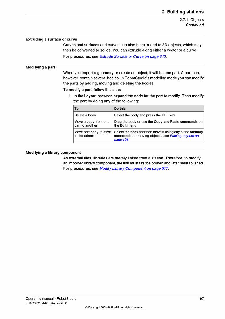
Extruding a surface or curveCurves and surfaces and curves can also be extruded to 3D objects, which maythen be converted to solids. You can extrude along either a vector or a curve.For procedures, see Extrude Surface or Curve on page 340.
Modifying a partWhen you import a geometry or create an object, it will be one part. A part can,however, contain several bodies. In RobotStudio’s modeling mode you can modifythe parts by adding, moving and deleting the bodies.To modify a part, follow this step:
1 In the Layout browser, expand the node for the part to modify. Then modifythe part by doing any of the following:
Do thisTo
Select the body and press the DEL key.Delete a body
Drag the body or use the Copy and Paste commands onthe Edit menu.
Move a body from onepart to another
Select the body and then move it using any of the ordinarycommands for moving objects, see Placing objects onpage 101.
Move one body relativeto the others
Modifying a library componentAs external files, libraries are merely linked from a station. Therefore, to modifyan imported library component, the link must first be broken and later reestablished.For procedures, see Modify Library Component on page 517.
Operating manual - RobotStudio 973HAC032104-001 Revision: X
© Copyright 2008-2018 ABB. All rights reserved.
2 Building stations2.7.1 Objects
Continued
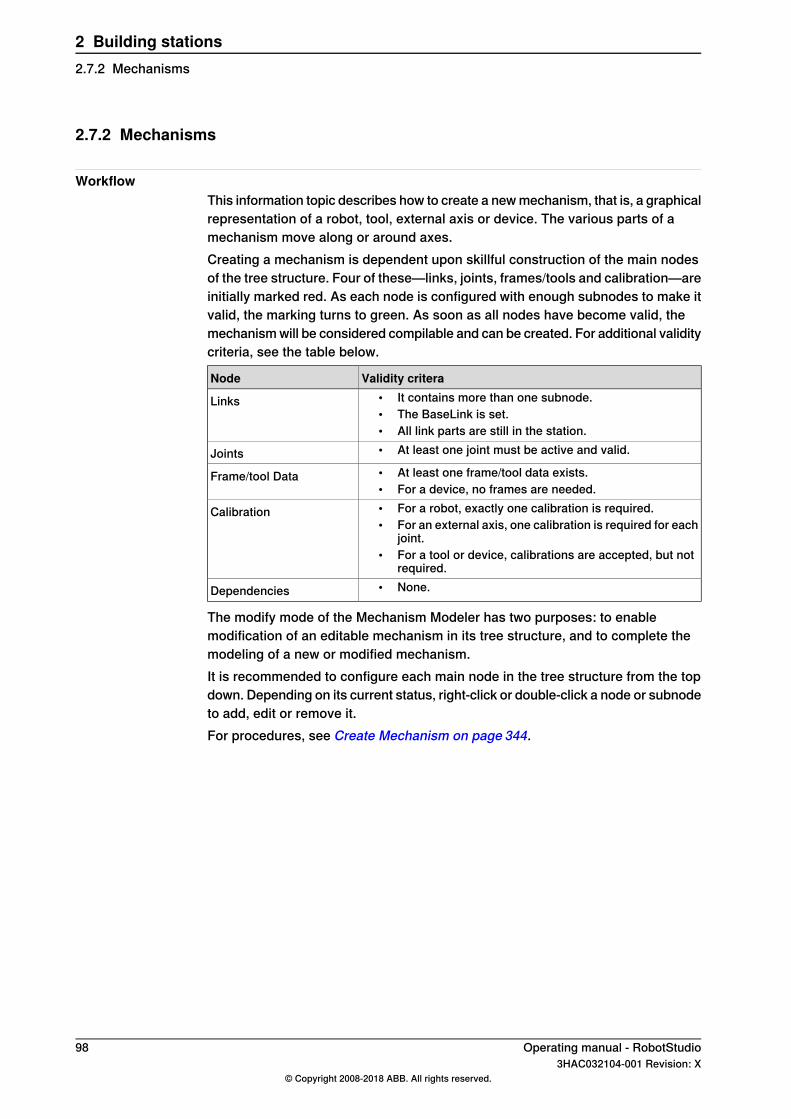
2.7.2 Mechanisms
WorkflowThis information topic describes how to create a new mechanism, that is, a graphicalrepresentation of a robot, tool, external axis or device. The various parts of amechanism move along or around axes.Creating a mechanism is dependent upon skillful construction of the main nodesof the tree structure. Four of these—links, joints, frames/tools and calibration—areinitially marked red. As each node is configured with enough subnodes to make itvalid, the marking turns to green. As soon as all nodes have become valid, themechanism will be considered compilable and can be created. For additional validitycriteria, see the table below.
Validity criteraNode• It contains more than one subnode.• The BaseLink is set.• All link parts are still in the station.
Links
• At least one joint must be active and valid.Joints• At least one frame/tool data exists.• For a device, no frames are needed.
Frame/tool Data
• For a robot, exactly one calibration is required.• For an external axis, one calibration is required for each
joint.• For a tool or device, calibrations are accepted, but not
required.
Calibration
• None.Dependencies
The modify mode of the Mechanism Modeler has two purposes: to enablemodification of an editable mechanism in its tree structure, and to complete themodeling of a new or modified mechanism.It is recommended to configure each main node in the tree structure from the topdown. Depending on its current status, right-click or double-click a node or subnodeto add, edit or remove it.For procedures, see Create Mechanism on page 344.
98 Operating manual - RobotStudio3HAC032104-001 Revision: X
© Copyright 2008-2018 ABB. All rights reserved.
2 Building stations2.7.2 Mechanisms

2.7.3 Tools and tooldata
OverviewTo simulate the robot tool, you need tooldata for the tool. If you import a predefinedtool or if you create a tool using the Create Tool Wizard, the tooldata isautomatically created; otherwise, you have to create the tooldata yourself.The tooldata simplifies the programming work with respect to the different toolsthat may come in use. Defining separate sets of tooldata for different tools makesit possible to run the same robot program with different tools: only the new tooldatahas to be defined. The tooldata contains the information required for moving andsimulating the tool.Two methods for manipulating tooldata in RobotStudio are as follows:
• Create or modify tooldata, see Tooldata on page242 andModify Tooldata onpage 528, respectively. This will create all data necessary for programming,but there will be no visual tool during the simulation.
• Create tooldata for an existing geometry, Create Tool on page 351.
Creating and setting up a stationary toolThis information topic describes how to create a stationary tool. For informationabout creating a robot hold tool, see Create Tool on page 351.Using a stationary tool, the robot holds and moves the work piece in relation tothe tool. Thus, both the tooldata and the workobject must be set up correctly.To create the tooldata for a stationary tool, follow these steps:
1 Import the geometry or library that represents the tool, see Import Geometryon page 236.If you do not have the geometry or library at hand but know the position, youcan skip this step. The tool will be programable, but not visible in the station.
2 Create the tooldata for the tool, see Tooldata on page 242.Make sure to set the Robot holds tool option to false.
3 Create a workobject that is moved by the robot. seeWorkobject on page241.Make sure to set the Robot holds workobject option to true.
4 If you have a geometry or library component for the work piece, attach it tothe robot, see Attach to on page 496.
Operating manual - RobotStudio 993HAC032104-001 Revision: X
© Copyright 2008-2018 ABB. All rights reserved.
2 Building stations2.7.3 Tools and tooldata

2.7.4 Setting the local origin of an object
OverviewEach object has a coordinate system of its own called local coordinate system inwhich the object dimensions are defined. When the object’s position is referredfrom other coordinate system, it is the origin of this coordinate system that is used.With the Set Local Origin command you reposition the object’s local coordinatesystem, not the object itself.For a procedure, see Set Local Origin on page 541.
100 Operating manual - RobotStudio3HAC032104-001 Revision: X
© Copyright 2008-2018 ABB. All rights reserved.
2 Building stations2.7.4 Setting the local origin of an object

2.8 Placement
2.8.1 Placing objects
OverviewTo achieve the required layout of your station, you need to import or create objects,place them accordingly and, if applicable, attach them to other objects.Placing objects means setting their position and rotation. If the objects are to beattached to robots or other mechanisms, they will be placed at their attachmentpoint automatically.The following table describes the actions relating to placement:
DescriptionActions
To place an object is to put the object in the required positionin the station, see Place on page 533 and Set Position onpage 543.
Placing an object
The objects in the station can be rotated to achieve the requiredlayout, see Rotate on page 539.
Rotating an object
The measurement functions calculates distances, angles anddiameters between points you select from the graphics window.
Measuring distance orangles
When using measurements, results and instructions on howto proceed are displayed in the Output window, see TheMeasure Group on page 343.
A component group groups related object in the browser, seeComponent Group on page 286.
Creating a componentgroup
Objects that are to be used by the robots in any way, such astools, need to be attached to the robot, seeAttach to on page496and Detach on page 503.
Attaching or detaching anobject
Robots can be placed by jogging. The robot axes can also bepostioned by jogging, see Jogging mechanisms on page 109.
Jogging a robot
Modifying the task frame repositions a controller and all its ro-bots and equipment in the station.
Modifying the task frame
By default the controller world and the station world coordinatesystem coincide. This is convenient when building a stationwith one single controller. For a procedure, see Set TaskFrames on page 448.However, when you have several controllers in one station, orneed to reposition a controller in an existing station, you needto modify the Edit System on page 449.
Modifying the baseframe position sets an offset between thecontroller’s world coordinate system and the baseframe of themechanical unit.This is necessary when having several mech-anical units belonging to one controller, for example, severalrobots in MultiMove systems or when using positioner externalaxes. For a procedure, see Edit System on page 449.
Modifying the baseframeposition
Operating manual - RobotStudio 1013HAC032104-001 Revision: X
© Copyright 2008-2018 ABB. All rights reserved.
2 Building stations2.8.1 Placing objects
2.8.2 Placing external axes
OverviewWhen starting a system with a track or positioner external axis in a RobotStudiostation, you have to set up the system to load a model for the track or positionerand get the motions to work properly.
PrerequisitesThe system shall be created with support for track or positioner external axes, seeA system with support for one robot and one positioner external axis on page 177.
Attaching the robot to the trackTo attach the robot to the track, follow these steps:
1 In the Layout browser, drag the robot icon and drop it on the track icon.2 To the question Should the robot be coordinated with the track?, answer
Yes to be able to coordinate the track’s position with that of the robot in robotprograms. To program the track and the robot independently, answer No.
3 When asked if you want to restart the system, answer Yes.The track is now added to the system and ready to be programmed, seeProgramming external axes on page 136 for more information on how toprogram the track.
CAUTION
If you restart the system using the restart mode Reset controller, the setup isdeleted and the procedures described here must be performed again.
Placing the positioner in the stationTo place the positioner in the station, follow these steps:
1 Move the positioner to the desired position using any of the ordinary functionsfor placing and moving objects, see Placing objects on page 101.
2 Modify the baseframe position of each mechanical unit of the positionerexcept the INTERCH unit, if it exists. When asked if you want to restart thesystem, answer Yes.After the restart the system is updated with the positioner’s new location.Continue attaching fixtures and workobjects to the positioner.
Attaching objects to the positionerTo program robot motions on an object that is held by the positioner, the targetsmust be created in a workobject that is attached to the positioner. For a completevisual simulation, CAD models that are moved by the positioner should also beattached. To attach the objects, follow these steps:
1 Import the models of the fixture and the work piece if you do not have themin the station already, see Importing a station component on page 92.
Continues on next page102 Operating manual - RobotStudio
3HAC032104-001 Revision: X© Copyright 2008-2018 ABB. All rights reserved.
2 Building stations2.8.2 Placing external axes
2 Attach the fixture to the positioner, see Attaching and detaching objects onpage 75. When asked whether to keep the current position, answer No.If the positioner has several stations, you will be asked which one to attachthe object to.
3 Attach the work piece to the fixture. When asked whether to keep the currentposition, answer No.
4 Attach the workobject in which you will program the work piece to either thefixture, the work piece or the positioner. If you have defined calibrationpositions on either the work piece or the fixture, it is a good practice to usethat object. When asked whether to keep the current position, answer No.The positioner is now set up and ready to be programed, see Programmingexternal axes on page 136 for more information.
Tip
If the positioner is of an interchangeable type with several stations, you can eitherattach individual fixtures, work pieces and workobjects to each station flange,or you can use one set of objects that you attach and detach to the differentflanges by events.
CAUTION
If you restart the system using the restart mode Reset controller, the setup isdeleted and the procedures described here must be performed again.
Operating manual - RobotStudio 1033HAC032104-001 Revision: X
© Copyright 2008-2018 ABB. All rights reserved.
2 Building stations2.8.2 Placing external axes
Continued
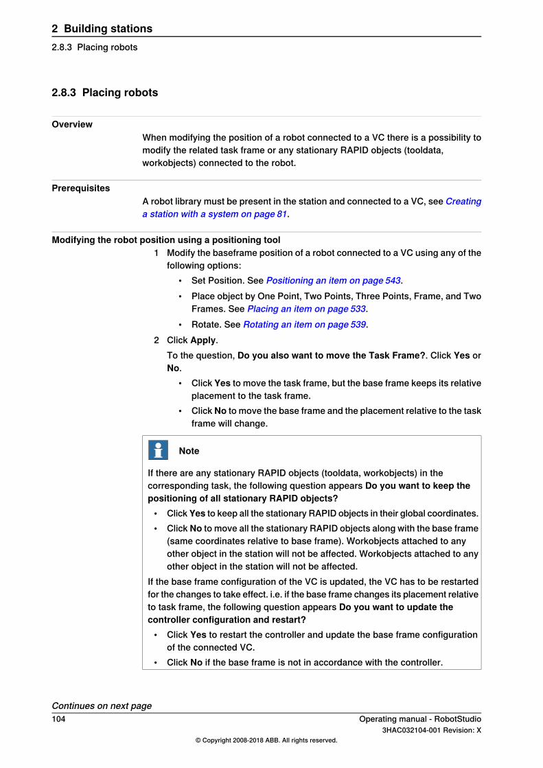
2.8.3 Placing robots
OverviewWhen modifying the position of a robot connected to a VC there is a possibility tomodify the related task frame or any stationary RAPID objects (tooldata,workobjects) connected to the robot.
PrerequisitesA robot library must be present in the station and connected to a VC, see Creatinga station with a system on page 81.
Modifying the robot position using a positioning tool1 Modify the baseframe position of a robot connected to a VC using any of the
following options:• Set Position. See Positioning an item on page 543.• Place object by One Point, Two Points, Three Points, Frame, and Two
Frames. See Placing an item on page 533.• Rotate. See Rotating an item on page 539.
2 Click Apply.To the question, Do you also want to move the Task Frame?. Click Yes orNo.
• Click Yes to move the task frame, but the base frame keeps its relativeplacement to the task frame.
• ClickNo to move the base frame and the placement relative to the taskframe will change.
Note
If there are any stationary RAPID objects (tooldata, workobjects) in thecorresponding task, the following question appears Do you want to keep thepositioning of all stationary RAPID objects?
• Click Yes to keep all the stationary RAPID objects in their global coordinates.• Click No to move all the stationary RAPID objects along with the base frame
(same coordinates relative to base frame). Workobjects attached to anyother object in the station will not be affected. Workobjects attached to anyother object in the station will not be affected.
If the base frame configuration of the VC is updated, the VC has to be restartedfor the changes to take effect. i.e. if the base frame changes its placement relativeto task frame, the following question appears Do you want to update thecontroller configuration and restart?
• Click Yes to restart the controller and update the base frame configurationof the connected VC.
• Click No if the base frame is not in accordance with the controller.
Continues on next page104 Operating manual - RobotStudio
3HAC032104-001 Revision: X© Copyright 2008-2018 ABB. All rights reserved.
2 Building stations2.8.3 Placing robots
Modifying the robot position using Freehand move or rotate1 Modify the baseframe position of a robot connected to a VC using the
following Freehand options:• Move. See The Freehand Group on page 267.• Rotate. See Rotating an item on page 268.
For information on updating the robot baseframe, seeUpdating the baseframeposition on page 449.
2 A warning message is displayed in the Output window.
Operating manual - RobotStudio 1053HAC032104-001 Revision: X
© Copyright 2008-2018 ABB. All rights reserved.
2 Building stations2.8.3 Placing robots
Continued

This page is intentionally left blank
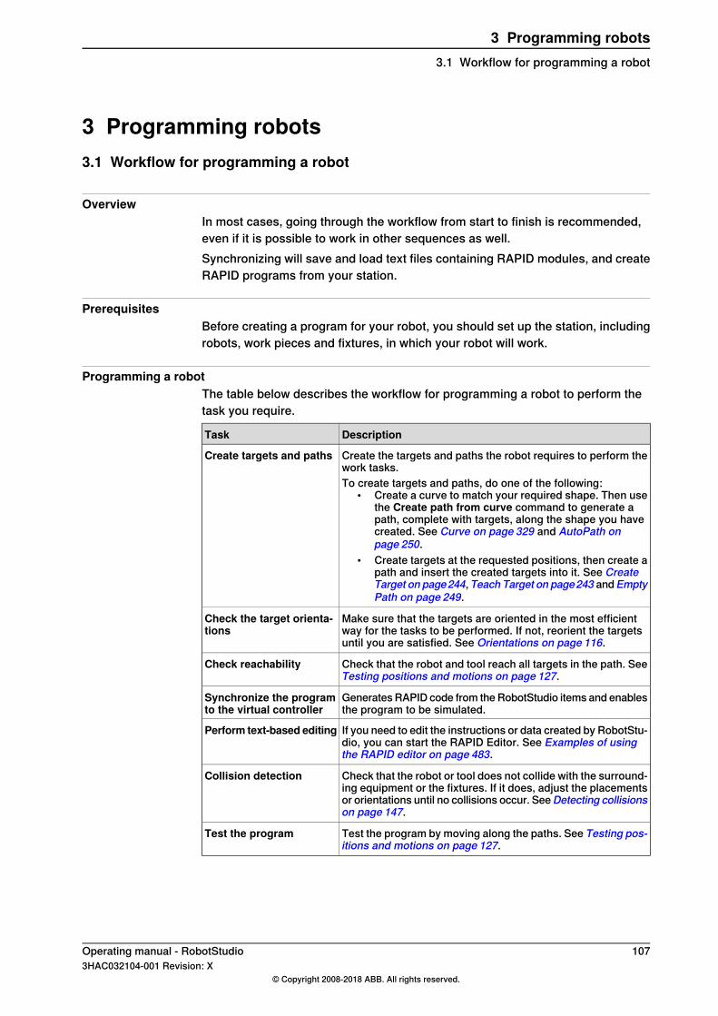
3 Programming robots3.1 Workflow for programming a robot
OverviewIn most cases, going through the workflow from start to finish is recommended,even if it is possible to work in other sequences as well.Synchronizing will save and load text files containing RAPID modules, and createRAPID programs from your station.
PrerequisitesBefore creating a program for your robot, you should set up the station, includingrobots, work pieces and fixtures, in which your robot will work.
Programming a robotThe table below describes the workflow for programming a robot to perform thetask you require.
DescriptionTask
Create the targets and paths the robot requires to perform thework tasks.
Create targets and paths
To create targets and paths, do one of the following:• Create a curve to match your required shape. Then use
the Create path from curve command to generate apath, complete with targets, along the shape you havecreated. See Curve on page 329 and AutoPath onpage 250.
• Create targets at the requested positions, then create apath and insert the created targets into it. See CreateTarget on page244, Teach Target on page243 andEmptyPath on page 249.
Make sure that the targets are oriented in the most efficientway for the tasks to be performed. If not, reorient the targetsuntil you are satisfied. See Orientations on page 116.
Check the target orienta-tions
Check that the robot and tool reach all targets in the path. SeeTesting positions and motions on page 127.
Check reachability
Generates RAPID code from the RobotStudio items and enablesthe program to be simulated.
Synchronize the programto the virtual controller
If you need to edit the instructions or data created by RobotStu-dio, you can start the RAPID Editor. See Examples of usingthe RAPID editor on page 483.
Perform text-based editing
Check that the robot or tool does not collide with the surround-ing equipment or the fixtures. If it does, adjust the placementsor orientations until no collisions occur. SeeDetecting collisionson page 147.
Collision detection
Test the program by moving along the paths. See Testing pos-itions and motions on page 127.
Test the program
Operating manual - RobotStudio 1073HAC032104-001 Revision: X
© Copyright 2008-2018 ABB. All rights reserved.
3 Programming robots3.1 Workflow for programming a robot

3.2 Workobjects
Creating a workobjectA workobject is a coordinate system used to describe the position of a work piece.The workobject consists of two frames: a user frame and an object frame. Allprogramed positions will be related to the object frame, which is related to the userframe, which is related to the world coordinate system.
xx050000
For creating a workobject, see Workobject on page 241.
Modifying a workobjectFor a procedure, see Modify Workobject on page 529.
Converting a frame to a workobjectYou can create a new workobject from an existing frame. The converted workobjectgets the same name and position as the selected frame.For a procedure, see Convert Frame to Workobject on page 499.
Creating a frame by pointsYou can create a frame by specfiying points on the axes of the coordinate systemand letting RobotStudio calulate the placement and orientation of the frame’s origin.For a procedure, see Frame from Three Points on page 239.
108 Operating manual - RobotStudio3HAC032104-001 Revision: X
© Copyright 2008-2018 ABB. All rights reserved.
3 Programming robots3.2 Workobjects

3.3 Jogging mechanisms
Jogging a robotTo check if the robot can reach all positions on the work piece, you can jog theTCP or the joints of the robot, either with the freehand commands of through dialogboxes. Jogging the robot close to its boudaries is best done with the latter method.
ProcedureTo
For freehand, see Jog Joint on page269. For a dialog box, seeMechanism Joint Jog on page 518.
Jog the joints of a robot
For freehand, see Jog Linear on page270. For a dialog box, seeMechanism Linear Jog on page 520.
Jog the TCP of a robot
PrerequisitesTo jog the TCP of a robot, the robot’s VC must be running.
Jogging several mechanisms
DescriptionFunction
When using multirobot jog, all selected mechanisms will followthe TCP of the one being jogged.
Mutlirobot jog
Multirobot jog is available for all kinds of jogging.See MultiRobot Jog on page 272.
When jogging a mechanism that moves a robot (like a trackexternal axis) with locked TCP, the robot will reposition so thatthe position of the TCP does not change, even though itsbaseframe is moved.
Jogging with locked TCP
When jogging an external axis that moves the work object withlocked TCP, the robot will reposition so that its TCP followsthe work object in the same way as when using multirobot jog.Locked TCP is available when jogging a mechanism that be-longs to the same task as a robot.See Mechanism Joint Jog on page 518.
Operating manual - RobotStudio 1093HAC032104-001 Revision: X
© Copyright 2008-2018 ABB. All rights reserved.
3 Programming robots3.3 Jogging mechanisms

3.4 Targets
Creating a targetYou can create a new target manually either by entering the position for the targetin the Create Target dialog box or by clicking in the graphics window.The target will be created in the active workobject.For a procedure, see Create Target on page 244.
Creating a jointtargetA jointtarget is a specification of the position for the robot axes.For a procedure, see Create Jointtarget on page 246.
Teaching targetsYou can create a new target by jogging the robot and teaching a target at the activeTCP. Taught targets will be created with the axis configuration used when joggedto the target.The target will be created in the active workobject.For a procedure, see Teach Target on page 243.
Modifying a target positionBy using the modify position command you can modify the position and rotationof a target.For procedures, see Set Position on page543 andRotate on page539, respectively.
Modifying a target with ModPosThe position of an existing target can be modified by jogging the robot to a new,preferred position. By selecting a move instruction for the target in a path, theModPos command can be used to move the target to the TCP of the active tool.When ModPos is executed, the target, referenced to by the move instruction, willbe updated with the following information:
• position and orientation corresponding to the TCP of the active tool• the current configuration of the active robot• the current position and orientation values of all active external axes for the
active robot
Note
To jog a robot linearly, a virtual controller must be running for that robot. Fordetailed information, see Starting a VC on page 90.
Renaming targetsWith this command you can change the name of several targets at once. You caneither rename targets individually, or you can rename all targets in one or severalpaths at once.
Continues on next page110 Operating manual - RobotStudio
3HAC032104-001 Revision: X© Copyright 2008-2018 ABB. All rights reserved.
3 Programming robots3.4 Targets

The new target names will consist of an optional prefix, an incremental numberand an optional suffix.For a precedure, see Rename Targets on page 537.When renaming targets, make sure that the new targets conform to the namingrules. The target names must:
• start with an alphabetical character in the ISO 8859-1 encoding (that is, anordinary letter from the English alphabet)
• be shorter than 16 characters• not be empty strings• not contain any characters illegal in RAPID. See RAPID reference manual
for details.
Removing unused targetsIf deleting or changing paths or move instructions during programming, you mightend up with large numbers of targets that are no longer used in any instructions.To make the workobjects and their targets easier to grasp, you can delete all unusedtargets.For a procedure, see Remove Unused Targets on page 536.
Operating manual - RobotStudio 1113HAC032104-001 Revision: X
© Copyright 2008-2018 ABB. All rights reserved.
3 Programming robots3.4 TargetsContinued
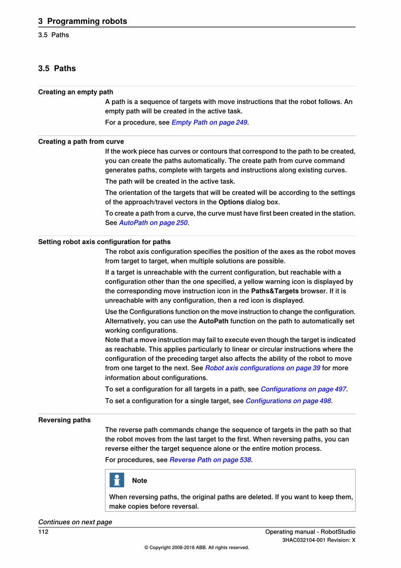
3.5 Paths
Creating an empty pathA path is a sequence of targets with move instructions that the robot follows. Anempty path will be created in the active task.For a procedure, see Empty Path on page 249.
Creating a path from curveIf the work piece has curves or contours that correspond to the path to be created,you can create the paths automatically. The create path from curve commandgenerates paths, complete with targets and instructions along existing curves.The path will be created in the active task.The orientation of the targets that will be created will be according to the settingsof the approach/travel vectors in the Options dialog box.To create a path from a curve, the curve must have first been created in the station.See AutoPath on page 250.
Setting robot axis configuration for pathsThe robot axis configuration specifies the position of the axes as the robot movesfrom target to target, when multiple solutions are possible.If a target is unreachable with the current configuration, but reachable with aconfiguration other than the one specified, a yellow warning icon is displayed bythe corresponding move instruction icon in the Paths&Targets browser. If it isunreachable with any configuration, then a red icon is displayed.Use the Configurations function on the move instruction to change the configuration.Alternatively, you can use the AutoPath function on the path to automatically setworking configurations.Note that a move instruction may fail to execute even though the target is indicatedas reachable. This applies particularly to linear or circular instructions where theconfiguration of the preceding target also affects the ability of the robot to movefrom one target to the next. See Robot axis configurations on page 39 for moreinformation about configurations.To set a configuration for all targets in a path, see Configurations on page 497.To set a configuration for a single target, see Configurations on page 498.
Reversing pathsThe reverse path commands change the sequence of targets in the path so thatthe robot moves from the last target to the first. When reversing paths, you canreverse either the target sequence alone or the entire motion process.For procedures, see Reverse Path on page 538.
Note
When reversing paths, the original paths are deleted. If you want to keep them,make copies before reversal.
Continues on next page112 Operating manual - RobotStudio
3HAC032104-001 Revision: X© Copyright 2008-2018 ABB. All rights reserved.
3 Programming robots3.5 Paths
Note
When reversing paths, only move instructions are handled. Action instructions,if any exist, have to be inserted manually after the reversal.
Rotating pathsWith the rotate path command you can rotate complete paths and move the targetsused by the paths accordingly. When rotating paths, the included targets will losetheir axis configurations, if any have been assigned.A frame or target must exist at the position to rotate around before starting therotate path command.For a procedure, see Rotate Path on page 540.
Translating a pathThe translate path function moves a path and all included targets.For a procedure, see Translate Path on page 545.
Compensating paths for tool radiusYou can offset a path so that it compensates for the radius of a rotating tool. Sincethe targets in the path are moved, they will lose their axis configurations, if anyhave been assigned.For a procedure, see Tool Compensation on page 544.
Interpolating a pathThe interpolate functions reorient the targets in a path so that the difference inorientation between the start and end targets is distributed evenly among thetargets in between. The interpolation can be either linear or absolute.Linear interpolation distributes the difference in orientation evenly, based on thetargets’ positions along the length of the path.Absolute interpolation distributes the difference in orientation evenly, based onthe targets’ sequence in the path.Below are examples of the difference bewteen linear and absolute interpolation.The interpolate functions reorient the targets in a path so that the difference inorientation between the start and end targets is distributed evenly among thetargets in between. The interpolation can be either linear or absolute.
Continues on next pageOperating manual - RobotStudio 1133HAC032104-001 Revision: X
© Copyright 2008-2018 ABB. All rights reserved.
3 Programming robots3.5 PathsContinued

For a procedure, see Interpolate Path on page 513.
No interpolationThis is the path before any interpolation. Note that the last target is orienteddifferently than the others.
xx050026
Linear interpolationThis is the same path after linear interpolation.
xx050027
Note that the targets are oriented based on their placement relative to the startand end targets.If a target were moved and you reran the linear interpolation, it would be reorientedaccording to its new position.If new targets were inserted between the existing ones and you reran the linearinterpolation, it would not affect the orientation of the existing targets.
Absolute interpolationThis is the same path after absolute interpolation
xx050028
Note that the targets are orientated based on their sequence in the path: eachtarget has been reoriented equally, regardless of its place.If a target were moved and you reran the absolute interpolation, it would not affectthe orientation.If new targets were inserted between the existing ones and you reran the absoluteinterpolation, it would change the orientation of all targets.
Continues on next page114 Operating manual - RobotStudio
3HAC032104-001 Revision: X© Copyright 2008-2018 ABB. All rights reserved.
3 Programming robots3.5 PathsContinued
Mirroring a pathThe mirror path function mirrors all motions instructions and their targets to a newpath.For a procedure, see Mirror Path on page 521.
Operating manual - RobotStudio 1153HAC032104-001 Revision: X
© Copyright 2008-2018 ABB. All rights reserved.
3 Programming robots3.5 PathsContinued
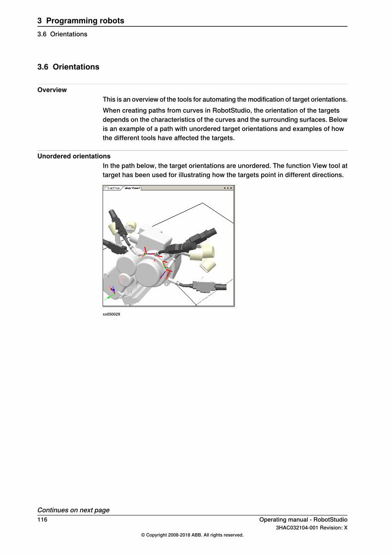
3.6 Orientations
OverviewThis is an overview of the tools for automating the modification of target orientations.When creating paths from curves in RobotStudio, the orientation of the targetsdepends on the characteristics of the curves and the surrounding surfaces. Belowis an example of a path with unordered target orientations and examples of howthe different tools have affected the targets.
Unordered orientationsIn the path below, the target orientations are unordered. The function View tool attarget has been used for illustrating how the targets point in different directions.
xx050029
Continues on next page116 Operating manual - RobotStudio
3HAC032104-001 Revision: X© Copyright 2008-2018 ABB. All rights reserved.
3 Programming robots3.6 Orientations
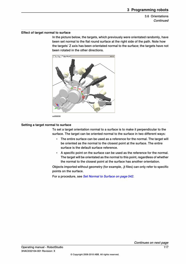
Effect of target normal to surfaceIn the picture below, the targets, which previously were orientated randomly, havebeen set normal to the flat round surface at the right side of the path. Note howthe targets’ Z axis has been orientated normal to the surface; the targets have notbeen rotated in the other directions.
xx050030
Setting a target normal to surfaceTo set a target orientation normal to a surface is to make it perpendicular to thesurface. The target can be oriented normal to the surface in two different ways:
• The entire surface can be used as a reference for the normal. The target willbe oriented as the normal to the closest point at the surface. The entiresurface is the default surface reference.
• A specific point on the surface can be used as the reference for the normal.The target will be orientated as the normal to this point, regardless of whetherthe normal to the closest point at the surface has another orientation.
Objects imported without geometry (for example, .jt files) can only refer to specificpoints on the surface.For a procedure, see Set Normal to Surface on page 542.
Continues on next pageOperating manual - RobotStudio 1173HAC032104-001 Revision: X
© Copyright 2008-2018 ABB. All rights reserved.
3 Programming robots3.6 Orientations
Continued
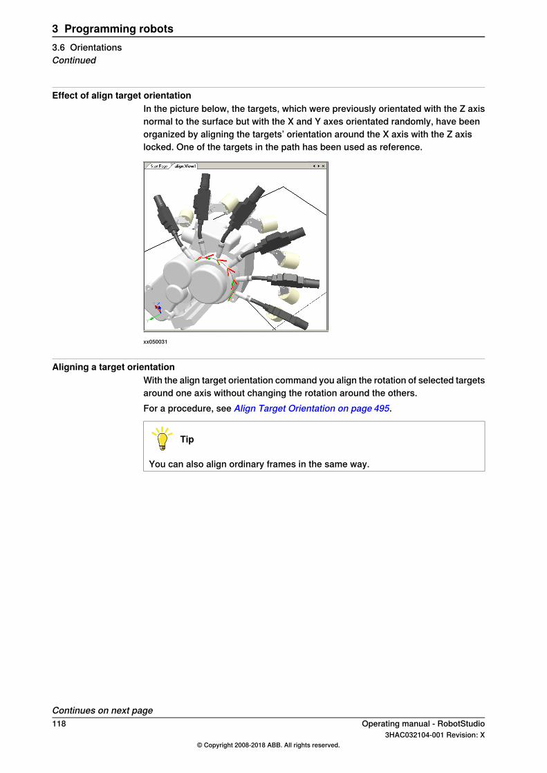
Effect of align target orientationIn the picture below, the targets, which were previously orientated with the Z axisnormal to the surface but with the X and Y axes orientated randomly, have beenorganized by aligning the targets’ orientation around the X axis with the Z axislocked. One of the targets in the path has been used as reference.
xx050031
Aligning a target orientationWith the align target orientation command you align the rotation of selected targetsaround one axis without changing the rotation around the others.For a procedure, see Align Target Orientation on page 495.
Tip
You can also align ordinary frames in the same way.
Continues on next page118 Operating manual - RobotStudio
3HAC032104-001 Revision: X© Copyright 2008-2018 ABB. All rights reserved.
3 Programming robots3.6 OrientationsContinued

Effects of copy and apply orientationIn the picture below, the targets, which were previously oriented randomly, havebeen organized by copying the exact orientation of one target to all the others.This is a quick way to fix workable orientations for processes where variations inapproach, travel, or spin directions either do not matter or are not affected, due tothe shape of the work piece.
xx050032
Copying and applying an orientation for objectsTo transfer an orientation from one object to another is an easy way to align differentframes for simplifying the programming of the robot. Target orientations may alsobe copied.For procedures, see Copy / Apply Orientation on page 502.
Operating manual - RobotStudio 1193HAC032104-001 Revision: X
© Copyright 2008-2018 ABB. All rights reserved.
3 Programming robots3.6 Orientations
Continued
3.7 RAPID Instructions
Note
For information on the RAPID Editor, which is used for creating and modifyingRAPID program code, see RAPID tab on page 451.
Move and action instructionsFor RAPID programming, RobotStudio’s main advantage is in the area of motionprogramming.A move instruction is an instruction for the robot to move to a specified target ina specified manner. With RobotStudio, you can create move instructions in threeways:
DescriptionMethod
Creates move instructions based on one or several targetsselected in the Paths&Targets browser. For a procedure, seeAdd to Path on page 493.
Create a move instructionbased on an existing target
Creates a move instruction and a corresponding target atonce. The position of the target can either be selected fromthe graphics window or typed numerically. For a procedure,see Move Instruction on page 261.
Create a move instructionand a corresponding target
Teaching a move instruction creates a move instruction anda corresponding target at the robot’s current position.Teaching a move instruction also stores the current configur-ation with the target. For a procedure, see Teach Instructionon page 260.
Teach a move instruction
In addition to move instructions, you can also create and insert action instructionsfrom RobotStudio. An action instruction is an instruction other than a moveinstruction that can, for example, set parameters, or activate or deactivateequipment and functions. The action instructions available in RobotStudio arelimited to those commonly used for affecting the robot’s motions. For insertingother action instructions or another kind of RAPID code in the program, use theRAPID Editor. For a procedure, see Action Instruction on page 262.The table below lists the action instructions that can be created. For details, seethe RAPID Reference Manual.
DescriptionAction instruction
ConfL specifies whether to monitor the robot’s configurationsduring linear movements. When ConfL is set to Off, the robotmay use another configuration than the programed one forreaching the target during program execution.
ConfL On/Off
ConfJ specifies whether to monitor the robot’s configurationsduring joint movements. When ConfJ is set to Off, the robotmay use another configuration than the programed one forreaching the target during program execution.
ConfJ On/Off
Actunit activates the mechanical unit specified by UnitName.Actunit UnitName
Deactunit deactivates the mechanical unit specified by Unit-Name.
DeactUnit UnitName
Continues on next page120 Operating manual - RobotStudio
3HAC032104-001 Revision: X© Copyright 2008-2018 ABB. All rights reserved.
3 Programming robots3.7 RAPID Instructions

DescriptionAction instruction
ConfJ specifies whether to monitor the robot’s configurationsduring joint movements. When ConfJ is set to Off, the robotmay use another configuration than the programed one forreaching the target during program execution.
ConfJ On/Off
Actunit activates the mechanical unit specified by UnitName.Actunit UnitName
Deactunit deactivates the mechanical unit specified by Unit-Name.
DeactUnit UnitName
Modifying an instructionMost instructions have arguments that specify how the instruction shall be carriedout. For example, the MoveL instruction has arguments that specify the speed andaccuracy with which the robot moves to the target.For a procedure, see Modify Instruction on page 526.
Note
Some arguments are read from the virtual controller. If the virtual controller hasnot been started, only the arguments stored in the station can be modified.
Converting to move circularTo create a circular motion to an instruction target, you must convert the motiontype to circular motion (that is, MoveC in RAPID).A circular motion is defined by two motion instructions, where the first is thevia-point and the second contains the end point of the circular motion.The circular motion can only be used for open circular arcs, not for closed circles.To create a path for a closed circle, use two circular motions.For a procedure, see Convert to Move Circular on page 501.
Creating RAPID instructions for setting I/O signalsFor controlling I/O signals in the robot program, you use RAPID commands thatset the signals. These require that you first create instruction templates for theinstructions that set the signals. See RAPID reference manual for details about theinstructions that control I/O signals.To add RAPID instructions that set I/O signals, follow these steps:
1 Synchronize the system in which you want to add the instructions to thevirtual controller, see Synchronization on page 139.
2 In programming mode, select the module for editing, right-click it and thenclick Edit program.
3 In the RAPID editor, add the instructions for setting the signals.4 When you are done adding instructions, synchronize the task and paths from
the Virtual Controller back to the station.
Continues on next pageOperating manual - RobotStudio 1213HAC032104-001 Revision: X
© Copyright 2008-2018 ABB. All rights reserved.
3 Programming robots3.7 RAPID Instructions
Continued
Using cross-connections and groups for setting I/O signalsYou can also create cross-connections and signal groups, which make one signalset the value of several other signals. See System parameters reference manualfor details about cross-connections and groups.To make one signal set several others, follow these steps:
1 Request write access, and then open the configuration topic I/O in theconfiguration editor. Add configure instances for the cross-connections andgroups to create.
Instruction templatesInstruction templates contain predefined sets of argument values that are appliedto the instructions you create using the template. You can create templates for allinstructions in the system running on the virtual controller. To see which instructionsare available and what their arguments do, see the RAPID reference manual foryour RobotWare version and the reference sections in manuals for software options,if you have any installed on the system.Move instruction templates are always part of process templates. The processtemplates contain one instruction template for each type of move instruction thatmight be used by the process.The process templates are instances of process definitions, which define the typesof move instructions (move instruction definitions) that might be used by theprocess.To create new move instruction templates, start by creating a new process templatefor a process that uses the type move instructions you want to create templatesfor. If such a process does not exist, you first have to create a new processdefinition.If no move instruction definition for the type of instruction you want to create atemplate for exists, you must create it first.When creating instruction descriptions, the virtual controller must be running, sincethe available instruction types are read from the system.Templates can be imported and exported on four levels: tasks, move instructiondescriptions, action instruction descriptions and process definitions. The defaultdirectory for imported and exported template files is My Documents/RobotStudio.Simply choosing another directory will then make that directory default. As a default.xml is the file format.The validation procedure checks for duplicate names, incomplete process definitionsand virtual controller equality. It is performed automatically, after a template filehas been imported or a node renamed or deleted.For procedures, see Instruction Template Manager on page 263.
Instruction Template ManagerThe Instruction Template Manager is used to add support for instructions otherthan the default set that comes with the RobotStudio.For example, a robot controller system with the RobotWare Dispense option hasspecialized move instructions related to glueing like DispL and DispC. You can
Continues on next page122 Operating manual - RobotStudio
3HAC032104-001 Revision: X© Copyright 2008-2018 ABB. All rights reserved.
3 Programming robots3.7 RAPID InstructionsContinued
manually define the instruction templates for these using the Instruction TemplateManager. The instruction templates are exported to XML format and reused later.The instruction template supports the following Robotware options:
• Cap (Continuous Application Process)• Disp (Dispense)• Trigg (Fixed Position Events)• Spot Pneumatic• Spot Servo• Spot Servo Equalizing• Paint
RobotStudio has pre-defined XML files that are imported and used for robotcontroller systems with the appropriate RobotWare options.These XML files hasboth the Move and Action instructions.
Note
Use RobotStudio ArcWelding PowerPac while using RobotWare Arc.
Creating a process template with move instruction templates
Note
Move instructions are always related to processes.
1 On the Home tab, from the active Task list, select the task for the robot forwhich you want to create the instruction template.
2 On the Create menu, click Instruction Template Manager. This opens theInstruction templates page in the work space.
3 In the Instruction Templates tree to the left, make sure there are moveinstruction definitions for the types of move instructions you want to createtemplates for. If not, follow the procedure in Creating a move instructiondescription on page 124 for creating them.
4 Make sure there is a process definition that uses the types of moveinstructions you want to create templates for. If not, follow the procedure inCreating a process definition on page 124 for creating it.
5 Right-click the process definition for which you want to create a new templatesand click Create Process Definition.
6 In the Create Process Definition dialog box, enter a name, with charactersfrom ASCII set, for the new template and clickCreate. A new process templatenode with a set of move instruction templates is now created.
7 Select each new template one at a time, and in the arguments grid to theright of the tree view, set the argument values that shall be applied when youcreate new instructions based on the template. Finish for each template byclicking Apply changes at the bottom of the grid.
Continues on next pageOperating manual - RobotStudio 1233HAC032104-001 Revision: X
© Copyright 2008-2018 ABB. All rights reserved.
3 Programming robots3.7 RAPID Instructions
Continued
For details about available arguments and what they do, see the RAPIDreference manual for ordinary RAPID instructions and the option manual forsoftware option instructions.
Creating a move instruction descriptionTo create templates for other instructions than the one that already exists in thetree view, you first have to create an instruction description that defines thearguments that belong to the instruction. To create the instruction description,follow these steps:
1 Right-click the Move Instructions node and click Create Move InstructionDescription. This opens the Create Move Instruction Description dialogbox.
2 In the Controller Description list, select the instruction you want to make adescription for. All action instructions installed on the controller, both throughRobotWare and software options, are available.
3 In the Motion type list, select the motion type for the instruction.4 Optionally, in the Information text box, enter a comment to the instruction.5 Click Create. The instruction description appears in the tree view and its
settings are displayed in the grid.6 In the instruction grid, set the point type values. If necessary, also change
the other settings.7 After changing the settings, click Apply Changes in the bottom of the grid
view.
Editing an instruction templateTo edit an instruction template, follow these steps:
1 In the active task list, select the task for the robot for which you want to editthe instruction template.
2 On the Create menu, click Instruction Template Manager. This opens theInstruction templates page in the work space.
3 In the Instruction Templates tree to the left, browse to and select the templateto edit.
4 In the arguments grid to the right of the tree view, set the argument valuesthat shall be applied when you create new instructions based on the template.Finish by clicking Apply changes at the bottom of the grid.For details about available arguments and what they do, see the RAPIDreference manual for ordinary RAPID instructions and the option manual forsoftware option instructions.
Creating a process definitionTo create a process definition, follow these steps:
1 Make sure there are move instruction definitions for the types of moveinstructions you want to create templates for. If not, follow the procedureabove for creating them.
Continues on next page124 Operating manual - RobotStudio
3HAC032104-001 Revision: X© Copyright 2008-2018 ABB. All rights reserved.
3 Programming robots3.7 RAPID InstructionsContinued
2 Right-click theProcess definitions node and clickCreate Process Definition.This opens the Create Process Description dialog box.
3 In the Create Process Definitions dialog box, enter a name for the processdefinition, a name for its first process template and then select the moveinstruction types to use. Finish by clicking Create.
Creating an action instruction templateTo create a template for an action instruction, follow these steps:
1 In the active task list, select the task for the robot for which you want to createthe instruction template.
2 On the Home menu, click Instruction Template Manager.3 In the Instruction Templates tree to the left, right-click the instruction
description (corresponding to the instructions as described in the RAPIDreference manual) for which you want to create a new template and clickCreate Action instruction Template.If the instruction description does not exist in the tree, create it by followingthe procedure described in Creating an action instruction description onpage 125.
4 In the Create Action Instruction Template dialog box, enter a name for thenew template and click Create. The new template is now created under theinstruction description node it belongs to.
5 Select the new template and in the arguments grid to the right of the treeview, set the argument values that shall be applied when you create newinstructions based on the template. Finish by clicking Apply changes at thebottom of the grid.For details about available arguments and what they do, see the RAPIDreference manual for ordinary RAPID instructions and the option manual forsoftware option instructions.
Creating an action instruction descriptionTo create templates for other instructions than the one that already exists in thetree view, you first have to create an instruction description that defines thearguments that belong to the instruction.To create the instruction description, follow these steps:
1 Right-click theAction Instructions node and clickCreate Action InstructionDescription. This opens the Create Instruction Description dialog box.
2 In the Controller Description list, select the instruction you want to make adescription for. All action instructions installed on the controller, both throughRobotWare and software options, are available.
3 Optionally, in the Information text box, enter a comment to the instruction.4 Click Create. The instruction description appears in the tree view, and its
settings are displayed in the grid.After changing the settings (if necessary), clickApply Changes in the bottomof the grid view.
Continues on next pageOperating manual - RobotStudio 1253HAC032104-001 Revision: X
© Copyright 2008-2018 ABB. All rights reserved.
3 Programming robots3.7 RAPID Instructions
Continued
5 Continue with creating templates for the instruction description, as describedin Creating an action instruction template on page 125.
126 Operating manual - RobotStudio3HAC032104-001 Revision: X
© Copyright 2008-2018 ABB. All rights reserved.
3 Programming robots3.7 RAPID InstructionsContinued

3.8 Testing positions and motions
OverviewRobotStudio has several functions for testing how robots reach and move to targets.They are useful both for finding the optimal layout when building a station andduring programming.Below are brief descriptions of the functions for testing reachability and motions.
Checking reachabilityThe reachability status of move instructions are displayed in the Paths&Targetsbrowser. The four states of reachability are as follows:
• Unknown (before checking)• Reachable (no indication)• Reachable with other configuration (yellow icon in browser)• Unreachable (red icon in browser and red move instruction in graphics view)
To change a configuration for all targets in a path, seeConfigurations on page497.To change a configuration for a single target, see Configurations on page 498.A target may be unreachable even though there is no indication by the moveinstruction and this is because the configuration may not allow the robot to movefrom the preceding target according to the specified motion type. This typicallyapplies to linear or circular move instructions where the robot is required to movealong a straight line or along a circular arc.The reachability of a target also depends on the tool and work object of the moveinstructions and hence the reachability status is only displayed in relation to moveinstructions.
Jumping to targetJump to target tests whether the robot can reach a specific position. This is usefulwhen building the station: by creating targets at critical positions on the work pieceand jumping the robot to them, you get an early indication of whether the itemsare positioned correctly or not. For a procedure, see Jump to Target on page 515.
Viewing a robot at targetWhen View robot at target is activated, the robot is automatically positioned withthe tool at the target when one is selected. If several robot axis configurations arepossible for reaching the target, the robot will use the one nearest the configurationit had before jumping to the target. For a procedure, see View Robot at Target onpage 546.
Viewing tool at targetView tool at target displays the tool at target, without checking that the robot canreach it. This test is useful both when building the station and when programmingthe robot, since the orientation of targets both affects the reachability and theprocess performance. For a procedure, see View Tool at Target on page 547.
Continues on next pageOperating manual - RobotStudio 1273HAC032104-001 Revision: X
© Copyright 2008-2018 ABB. All rights reserved.
3 Programming robots3.8 Testing positions and motions
Executing move instructionsExecute move instruction tests if the robot can reach a specific position with theprogramed motion properties. This is useful for testing motions during programming.For detailed information, see Execute Move Instruction on page 505.
Moving along pathMove along path executes all move instructions in a path. It is thereby a morecomplete test than Execute move instructions, but not as complete as a fullsimulation, since it ignores RAPID code that is not move instructions. For aprocedure, see Move Along Path on page 530.
Moving to a poseMoving to a pose moves a mechanism to a predefined joint value at a predefinedtime without using the Virtual Controller. This is useful when movement of theexternal equipment (such as a clamp or conveyer) must be simulated. For aprocedure, see Move to Pose on page 531.
Simulating programsSimulating programs involves running a program on the virtual controller as it isrun on a real controller. It is the most complete test whereby you can see how therobot interacts with external equipment through events and I/O signals. For aprocedure, see Simulation Setup on page 357.
Improving the reachabilityIf the robot cannot reach the target, or if you are not satisfied with the motions, trythe following for improving the reachability:
1 Set ConfL or ConfJ to Off for enabling the robot to use new configurationsfor reaching the target.
2 Change the orientation of the target.3 Change the position of either the robot or the work piece.4 Use a system with a track external axis for increasing the robot’s range.5 Use a system with a positioner external axis for enabling different work piece
positions for different targets.
128 Operating manual - RobotStudio3HAC032104-001 Revision: X
© Copyright 2008-2018 ABB. All rights reserved.
3 Programming robots3.8 Testing positions and motionsContinued

3.9 Programming MultiMove systems
3.9.1 About programming MultiMove
About MultiMoveThe MultiMove functions helps you create and optimize programs for MultiMovesystems where one robot or positioner holds the work piece and other robotsoperate on it. Below is an outline of the main workflow for programming MultiMovesystems with RobotStudio, with references to detailed instructions further downin the section.
PrerequisitesFor using the MultiMove functions you must first have the following:
• A virtual controller running a MultiMove system started in RobotStudio, seeAMultiMove systemwith two coordinated robots on page192 for an example.
• All coordinate systems and tools used by the system.• The paths along which the tool shall move. The paths must be created in a
workobject that belongs to a tool robot and is attached to the work piecerobot. A wizard will guide you through attaching the workobjects if this hasnot been done before starting the MultiMove functions.
For detailed information about MultiMove in RobotWare systems and RAPIDprograms, see MultiMove application manual.
Normal workflowThis is the typical workflow for creating MutliMove programs using the MultiMovefunction:
DescriptionAction
Select the robots and paths to use in the program, seeSetting up the MultiMove on page 131.
Setting up the MultiMove
Execute the motion instructions along the paths, seeTesting the MultiMove on page 132.
Testing the MultiMove
Tune motion behavior, such as tolerances and constraintsfor TCP motions, see Tuning the motion behavior onpage 133.
Tuning the motion behavior
Generate the tasks for the robots, see Creating paths onpage 135.
Creating the program
Continues on next pageOperating manual - RobotStudio 1293HAC032104-001 Revision: X
© Copyright 2008-2018 ABB. All rights reserved.
3 Programming robots3.9.1 About programming MultiMove
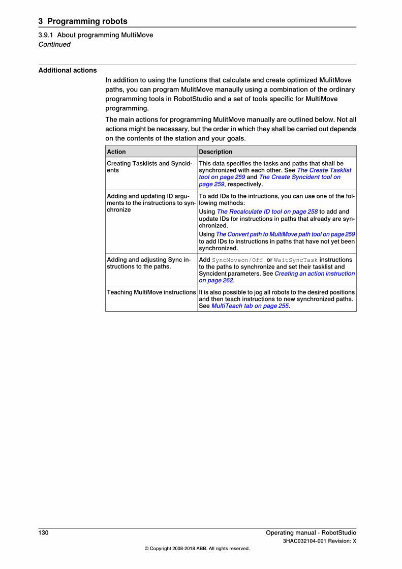
Additional actionsIn addition to using the functions that calculate and create optimized MulitMovepaths, you can program MulitMove manaully using a combination of the ordinaryprogramming tools in RobotStudio and a set of tools specific for MultiMoveprogramming.The main actions for programming MulitMove manually are outlined below. Not allactions might be necessary, but the order in which they shall be carried out dependson the contents of the station and your goals.
DescriptionAction
This data specifies the tasks and paths that shall besynchronized with each other. See The Create Tasklisttool on page 259 and The Create Syncident tool onpage 259, respectively.
Creating Tasklists and Syncid-ents
To add IDs to the intructions, you can use one of the fol-lowing methods:
Adding and updating ID argu-ments to the instructions to syn-chronize Using The Recalculate ID tool on page 258 to add and
update IDs for instructions in paths that already are syn-chronized.UsingTheConvert path toMultiMove path tool on page259to add IDs to instructions in paths that have not yet beensynchronized.
Add SyncMoveon/Off or WaitSyncTask instructionsto the paths to synchronize and set their tasklist andSyncident parameters. SeeCreating an action instructionon page 262.
Adding and adjusting Sync in-structions to the paths.
It is also possible to jog all robots to the desired positionsand then teach instructions to new synchronized paths.See MultiTeach tab on page 255.
Teaching MultiMove instructions
130 Operating manual - RobotStudio3HAC032104-001 Revision: X
© Copyright 2008-2018 ABB. All rights reserved.
3 Programming robots3.9.1 About programming MultiMoveContinued
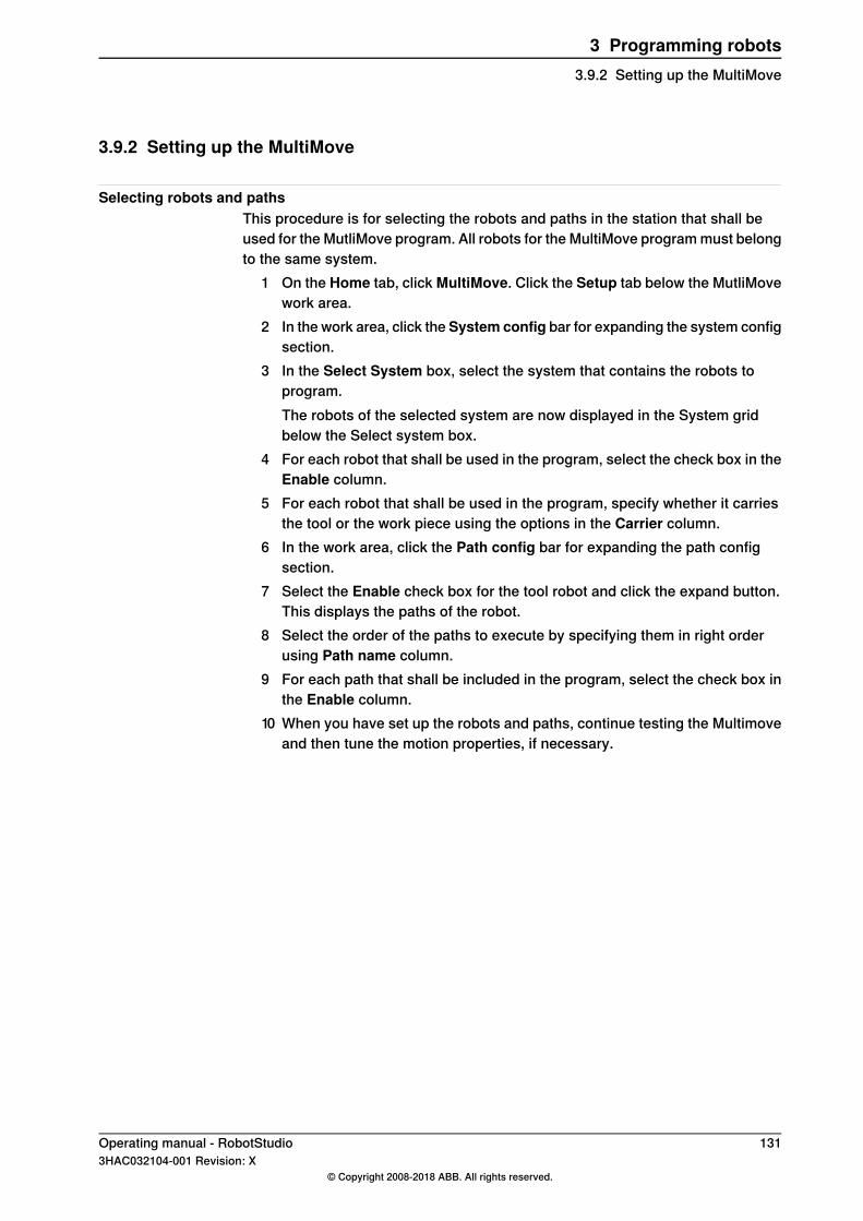
3.9.2 Setting up the MultiMove
Selecting robots and pathsThis procedure is for selecting the robots and paths in the station that shall beused for the MutliMove program. All robots for the MultiMove program must belongto the same system.
1 On the Home tab, click MultiMove. Click the Setup tab below the MutliMovework area.
2 In the work area, click the System config bar for expanding the system configsection.
3 In the Select System box, select the system that contains the robots toprogram.The robots of the selected system are now displayed in the System gridbelow the Select system box.
4 For each robot that shall be used in the program, select the check box in theEnable column.
5 For each robot that shall be used in the program, specify whether it carriesthe tool or the work piece using the options in the Carrier column.
6 In the work area, click the Path config bar for expanding the path configsection.
7 Select the Enable check box for the tool robot and click the expand button.This displays the paths of the robot.
8 Select the order of the paths to execute by specifying them in right orderusing Path name column.
9 For each path that shall be included in the program, select the check box inthe Enable column.
10 When you have set up the robots and paths, continue testing the Multimoveand then tune the motion properties, if necessary.
Operating manual - RobotStudio 1313HAC032104-001 Revision: X
© Copyright 2008-2018 ABB. All rights reserved.
3 Programming robots3.9.2 Setting up the MultiMove
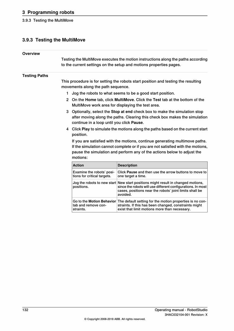
3.9.3 Testing the MultiMove
OverviewTesting the MultiMove executes the motion instructions along the paths accordingto the current settings on the setup and motions properties pages.
Testing PathsThis procedure is for setting the robots start position and testing the resultingmovements along the path sequence.
1 Jog the robots to what seems to be a good start position.2 On the Home tab, click MultiMove. Click the Test tab at the bottom of the
MultiMove work area for displaying the test area.3 Optionally, select the Stop at end check box to make the simulation stop
after moving along the paths. Clearing this check box makes the simulationcontinue in a loop until you click Pause.
4 Click Play to simulate the motions along the paths based on the current startposition.If you are satisfied with the motions, continue generating multimove paths.If the simulation cannot complete or if you are not satisfied with the motions,pause the simulation and perform any of the actions below to adjust themotions:
DescriptionAction
Click Pause and then use the arrow buttons to move toone target a time.
Examine the robots’ posi-tions for critical targets.
New start positions might result in changed motions,since the robots will use different configurations. In mostcases, positions near the robots’ joint limits shall beavoided.
Jog the robots to new startpositions.
The default setting for the motion properties is no con-straints. If this has been changed, constraints mightexist that limit motions more than necessary.
Go to the Motion Behaviortab and remove con-straints.
132 Operating manual - RobotStudio3HAC032104-001 Revision: X
© Copyright 2008-2018 ABB. All rights reserved.
3 Programming robots3.9.3 Testing the MultiMove
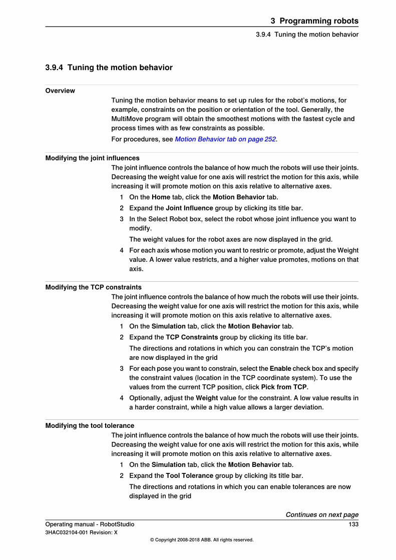
3.9.4 Tuning the motion behavior
OverviewTuning the motion behavior means to set up rules for the robot’s motions, forexample, constraints on the position or orientation of the tool. Generally, theMultiMove program will obtain the smoothest motions with the fastest cycle andprocess times with as few constraints as possible.For procedures, see Motion Behavior tab on page 252.
Modifying the joint influencesThe joint influence controls the balance of how much the robots will use their joints.Decreasing the weight value for one axis will restrict the motion for this axis, whileincreasing it will promote motion on this axis relative to alternative axes.
1 On the Home tab, click the Motion Behavior tab.2 Expand the Joint Influence group by clicking its title bar.3 In the Select Robot box, select the robot whose joint influence you want to
modify.The weight values for the robot axes are now displayed in the grid.
4 For each axis whose motion you want to restric or promote, adjust the Weightvalue. A lower value restricts, and a higher value promotes, motions on thataxis.
Modifying the TCP constraintsThe joint influence controls the balance of how much the robots will use their joints.Decreasing the weight value for one axis will restrict the motion for this axis, whileincreasing it will promote motion on this axis relative to alternative axes.
1 On the Simulation tab, click the Motion Behavior tab.2 Expand the TCP Constraints group by clicking its title bar.
The directions and rotations in which you can constrain the TCP’s motionare now displayed in the grid
3 For each pose you want to constrain, select the Enable check box and specifythe constraint values (location in the TCP coordinate system). To use thevalues from the current TCP position, click Pick from TCP.
4 Optionally, adjust the Weight value for the constraint. A low value results ina harder constraint, while a high value allows a larger deviation.
Modifying the tool toleranceThe joint influence controls the balance of how much the robots will use their joints.Decreasing the weight value for one axis will restrict the motion for this axis, whileincreasing it will promote motion on this axis relative to alternative axes.
1 On the Simulation tab, click the Motion Behavior tab.2 Expand the Tool Tolerance group by clicking its title bar.
The directions and rotations in which you can enable tolerances are nowdisplayed in the grid
Continues on next pageOperating manual - RobotStudio 1333HAC032104-001 Revision: X
© Copyright 2008-2018 ABB. All rights reserved.
3 Programming robots3.9.4 Tuning the motion behavior
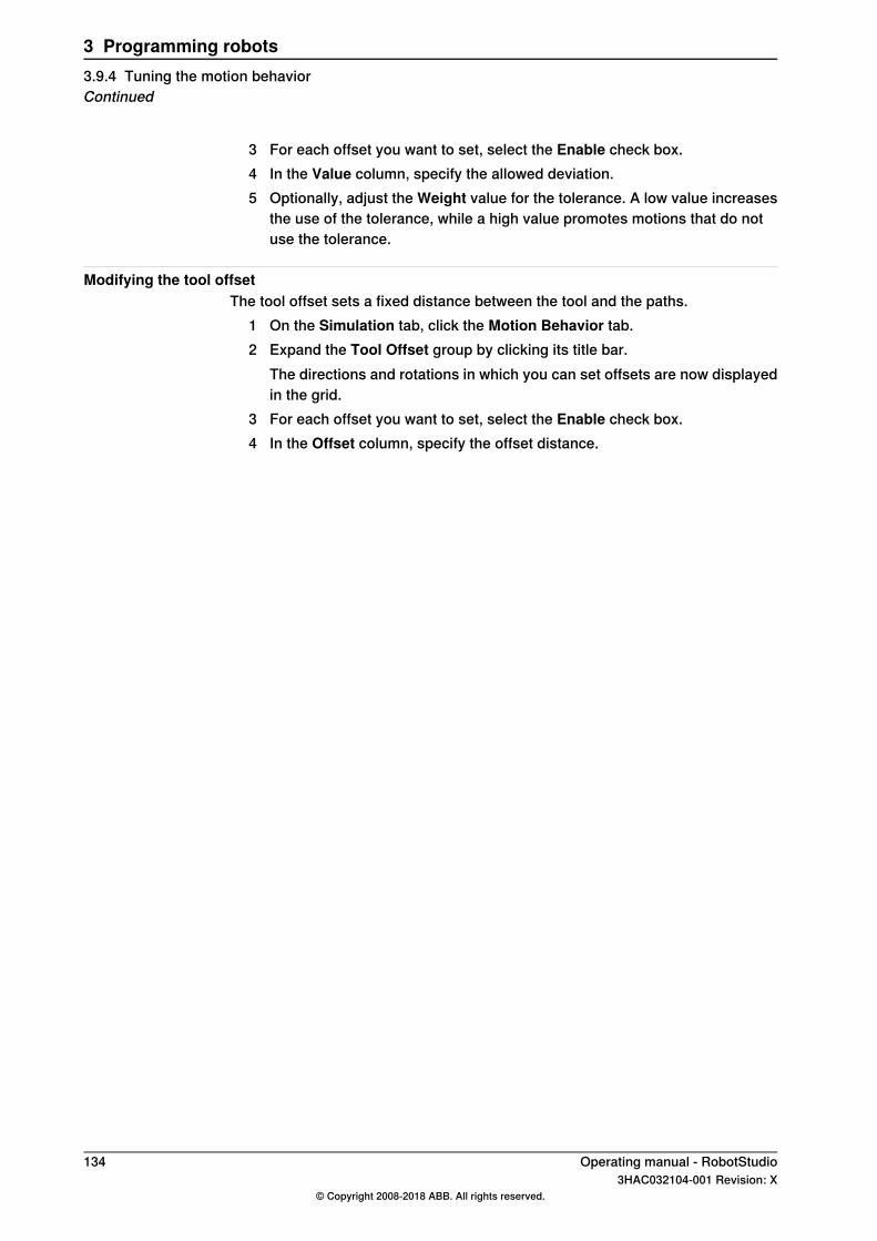
3 For each offset you want to set, select the Enable check box.4 In the Value column, specify the allowed deviation.5 Optionally, adjust the Weight value for the tolerance. A low value increases
the use of the tolerance, while a high value promotes motions that do notuse the tolerance.
Modifying the tool offsetThe tool offset sets a fixed distance between the tool and the paths.
1 On the Simulation tab, click the Motion Behavior tab.2 Expand the Tool Offset group by clicking its title bar.
The directions and rotations in which you can set offsets are now displayedin the grid.
3 For each offset you want to set, select the Enable check box.4 In the Offset column, specify the offset distance.
134 Operating manual - RobotStudio3HAC032104-001 Revision: X
© Copyright 2008-2018 ABB. All rights reserved.
3 Programming robots3.9.4 Tuning the motion behaviorContinued
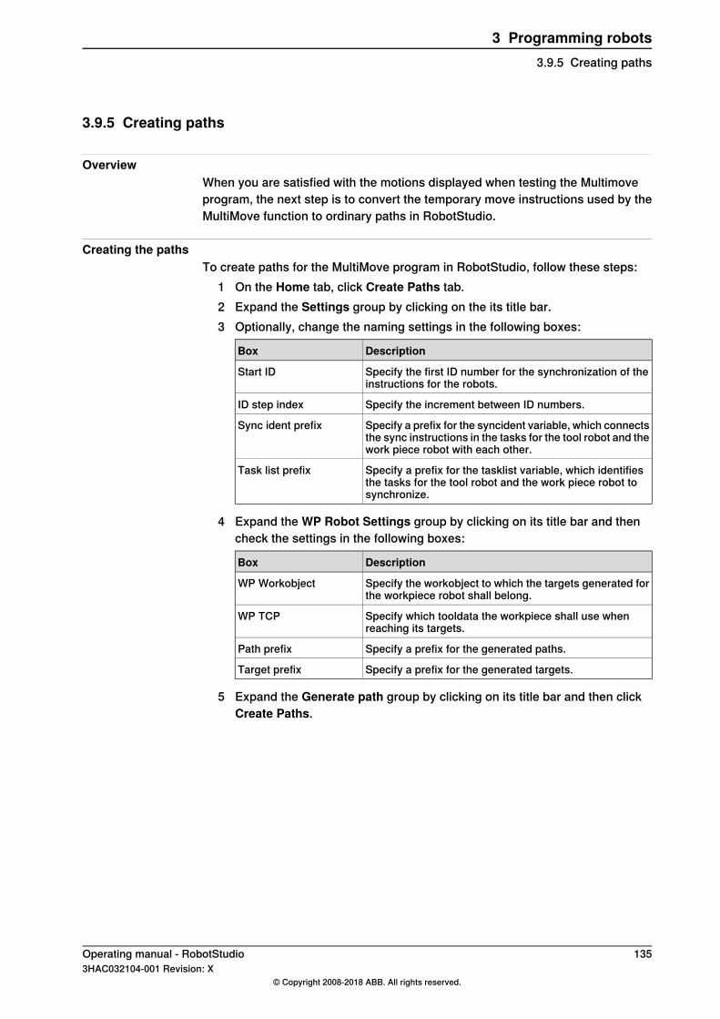
3.9.5 Creating paths
OverviewWhen you are satisfied with the motions displayed when testing the Multimoveprogram, the next step is to convert the temporary move instructions used by theMultiMove function to ordinary paths in RobotStudio.
Creating the pathsTo create paths for the MultiMove program in RobotStudio, follow these steps:
1 On the Home tab, click Create Paths tab.2 Expand the Settings group by clicking on the its title bar.3 Optionally, change the naming settings in the following boxes:
DescriptionBox
Specify the first ID number for the synchronization of theinstructions for the robots.
Start ID
Specify the increment between ID numbers.ID step index
Specify a prefix for the syncident variable, which connectsthe sync instructions in the tasks for the tool robot and thework piece robot with each other.
Sync ident prefix
Specify a prefix for the tasklist variable, which identifiesthe tasks for the tool robot and the work piece robot tosynchronize.
Task list prefix
4 Expand the WP Robot Settings group by clicking on its title bar and thencheck the settings in the following boxes:
DescriptionBox
Specify the workobject to which the targets generated forthe workpiece robot shall belong.
WP Workobject
Specify which tooldata the workpiece shall use whenreaching its targets.
WP TCP
Specify a prefix for the generated paths.Path prefix
Specify a prefix for the generated targets.Target prefix
5 Expand the Generate path group by clicking on its title bar and then clickCreate Paths.
Operating manual - RobotStudio 1353HAC032104-001 Revision: X
© Copyright 2008-2018 ABB. All rights reserved.
3 Programming robots3.9.5 Creating paths
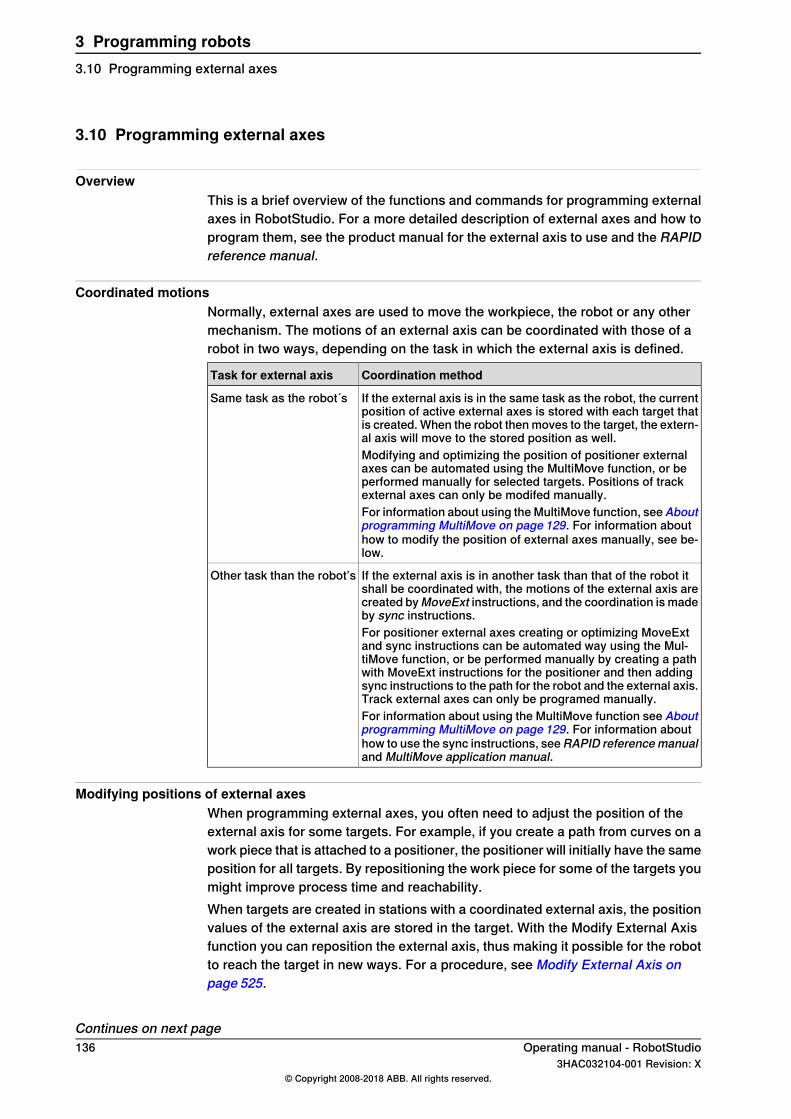
3.10 Programming external axes
OverviewThis is a brief overview of the functions and commands for programming externalaxes in RobotStudio. For a more detailed description of external axes and how toprogram them, see the product manual for the external axis to use and the RAPIDreference manual.
Coordinated motionsNormally, external axes are used to move the workpiece, the robot or any othermechanism. The motions of an external axis can be coordinated with those of arobot in two ways, depending on the task in which the external axis is defined.
Coordination methodTask for external axis
If the external axis is in the same task as the robot, the currentposition of active external axes is stored with each target thatis created. When the robot then moves to the target, the extern-al axis will move to the stored position as well.
Same task as the robot´s
Modifying and optimizing the position of positioner externalaxes can be automated using the MultiMove function, or beperformed manually for selected targets. Positions of trackexternal axes can only be modifed manually.For information about using the MultiMove function, seeAboutprogramming MultiMove on page 129. For information abouthow to modify the position of external axes manually, see be-low.
If the external axis is in another task than that of the robot itshall be coordinated with, the motions of the external axis arecreated byMoveExt instructions, and the coordination is madeby sync instructions.
Other task than the robot’s
For positioner external axes creating or optimizing MoveExtand sync instructions can be automated way using the Mul-tiMove function, or be performed manually by creating a pathwith MoveExt instructions for the positioner and then addingsync instructions to the path for the robot and the external axis.Track external axes can only be programed manually.For information about using the MultiMove function see Aboutprogramming MultiMove on page 129. For information abouthow to use the sync instructions, seeRAPID referencemanualand MultiMove application manual.
Modifying positions of external axesWhen programming external axes, you often need to adjust the position of theexternal axis for some targets. For example, if you create a path from curves on awork piece that is attached to a positioner, the positioner will initially have the sameposition for all targets. By repositioning the work piece for some of the targets youmight improve process time and reachability.When targets are created in stations with a coordinated external axis, the positionvalues of the external axis are stored in the target. With the Modify External Axisfunction you can reposition the external axis, thus making it possible for the robotto reach the target in new ways. For a procedure, see Modify External Axis onpage 525.
Continues on next page136 Operating manual - RobotStudio
3HAC032104-001 Revision: X© Copyright 2008-2018 ABB. All rights reserved.
3 Programming robots3.10 Programming external axes
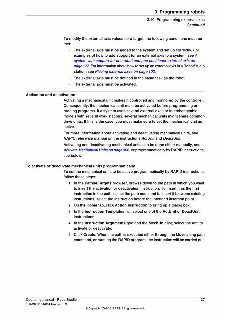
To modify the external axis values for a target, the following conditions must bemet:
• The external axis must be added to the system and set up correctly. Forexamples of how to add support for an external axis to a system, see Asystem with support for one robot and one positioner external axis onpage177. For information about how to set up an external axis in a RobotStudiostation, see Placing external axes on page 102.
• The external axis must be defined in the same task as the robot.• The external axis must be activated.
Activation and deactivationActivating a mechanical unit makes it controlled and monitored by the controller.Consequently, the mechanical unit must be activated before programming orrunning programs. If a system uses several external axes or interchangeablemodels with several work stations, several mechanical units might share commondrive units. If this is the case, you must make sure to set the mechanical unit asactive.For more information about activating and deactivating mechanical units, seeRAPID reference manual on the instructions ActUnit and DeactUnit.Activating and deactivating mechanical units can be done either manually, seeActivate Mechanical Units on page366, or programmatically by RAPID instructions,see below.
To activate or deactivate mechanical units programmaticallyTo set the mechanical units to be active programmatically by RAPID instructions,follow these steps:
1 In the Paths&Targets browser, browse down to the path in which you wantto insert the activation or deactivation instruction. To insert it as the firstinstruction in the path, select the path node and to insert it between existinginstructions, select the instruction before the intended insertion point.
2 On the Home tab, click Action Instruction to bring up a dialog box.3 In the Instruction Templates list, select one of the ActUnit or DeactUnit
instructions.4 In the Instruction Arguments grid and the MechUnit list, select the unit to
activate or deactivate.5 Click Create. When the path is executed either through the Move along path
command, or running the RAPID program, the instruction will be carried out.
Operating manual - RobotStudio 1373HAC032104-001 Revision: X
© Copyright 2008-2018 ABB. All rights reserved.
3 Programming robots3.10 Programming external axes
Continued
3.11 Loading and saving programs and modules
OverviewRAPID programs and modules are normally stored in the RobotWare systems, asthey are created. You can also save the programs to files on the PC, which makesit possible to load them to other controllers, either other virtual controllers or realIRC5 controllers.
Programs are saved from the VCWhen saving a program to files on the PC from RobotStudio, it is the RAPID programstored in the system of the VC that is saved. This program is created and updatedby synchronizing the station to the VC, see Synchronize to RAPID on page 453.
ProceduresTo create or load a module or load a program, see:
• Creating a new RAPID module on page 461• Loading a RAPID module on page 461• Loading a RAPID program on page 466
To save a module or program, see:• Saving a RAPID module on page 462• Saving a program on page 466
138 Operating manual - RobotStudio3HAC032104-001 Revision: X
© Copyright 2008-2018 ABB. All rights reserved.
3 Programming robots3.11 Loading and saving programs and modules
3.12 Synchronization
OverviewTo synchronize is to make sure that the RAPID program in the system running onthe virtual controller corresponds to the programs in RobotStudio. You cansynchronize both from RobotStudio to the virtual controller and from the virtualcontroller to RobotStudio.In a RobotStudio station, robot positions and movements are defined by targetsand move instructions in paths. These correspond to data declarations and RAPIDinstructions in the modules of the RAPID program. By synchronizing the stationto the virtual controller, you create RAPID code out of the data in the station. Bysynchronizing the virtual controller to the station, you create paths and targets outof the RAPID program in the system running on the virtual controller.
When to synchronize the station to the VCSynchronizing the station to the VC updates the RAPID program of the virtualcontroller with the latest changes in the station. This is useful to do before:
• Performing a simulation.• Saving a program to files on the PC.• Copying or loading RobotWare systems.
To synchronize a station to the VC, see Synchronize to RAPID on page 453.
When to synchronize the VC to the stationSynchronizing the VC to the station creates paths, targets and instructions thatcorrespond to the RAPID program in the system running on the virtual controller.This is useful to do when you have:
• Started a new virtual controller which system contains existing programs.• Loaded a program from a file.• Text-edited the program.
To synchronize the VC to a station, see Synchronize to Station on page 452.
Operating manual - RobotStudio 1393HAC032104-001 Revision: X
© Copyright 2008-2018 ABB. All rights reserved.
3 Programming robots3.12 Synchronization

This page is intentionally left blank

4 Deploying and distributing4.1 Copying programs
OverviewRAPID programs are normally stored in the systems that run on the virtualcontrollers of your station. To copy programs to systems on other controllers, savethe programs to file on the PC and then load these files to the destinationcontrollers. You can save either entire programs or specific modules.
Copying a programTo copy a program from one controller to another, follow these steps:
1 In the Controller browser, select the controller that contains the program tocopy.
2 Save the program to file on the disc. For details, see Saving a program onpage 466.
3 If necessary, copy the files to a location that is accessible to the othercontroller.
4 For instructions on loading the program to a system on a virtual controller,a FlexController or a non-running system, see the table below.
Do thisSystem location
See Loading a RAPID program on page 466.Virtual controller, runningin RobotStudio
Connect to the FlexController and load the program.FlexController
Start the system in a virtual controller, then load theprogram, see Adding a system on page 90 and Loadinga RAPID program on page 466, respectively.
A non-running systemstored on the PC
Operating manual - RobotStudio 1413HAC032104-001 Revision: X
© Copyright 2008-2018 ABB. All rights reserved.
4 Deploying and distributing4.1 Copying programs
4.2 Pack & Go / Unpack & Work
OverviewThe Pack & Go / Unpack & Work feature makes it possible to create a package(zip file) of an active station that can be unpacked on another computer. Thepackage contains all necessary files, except media pools, but add-in based mediapools are included.For procedures, see Pack and Go on page213 and Unpack andWork on page214.
142 Operating manual - RobotStudio3HAC032104-001 Revision: X
© Copyright 2008-2018 ABB. All rights reserved.
4 Deploying and distributing4.2 Pack & Go / Unpack & Work

4.3 Screen Capture
OverviewScreen capture entails two functions useful for demonstrations and trainingpurposes:
• The Screenshot function which allows you to capture an image of theapplication.
• The Record Movie function which allows you to make a recording of yourwork in RobotStudio, either of the entire GUI or just the graphics window.
Taking screenshotsThe Screenshot function allows you to capture an image of the entire applicationor an active document window such as the graphics window.
Note
The Screenshot feature is available only for RobotStudio Premium users.
Configure the options for the screenshot function as per your requirement underOptions:General:Screenshot in the File tab. For more information, seeOptions:General:Screenshot on page 220.You can take screenshots using the keyboard shortcut CTRL + B. Alternatively,you can use the Screenshot button on the Quick Access Toolbar, but you mustenable it first.To enable the screenshot command button:
1 Click the Quick Access Toolbar’s down arrow. The Customize Quick AccessToolbar menu is displayed.
2 Click Screenshot to add the check mark to the command. This adds thescreenshot button to the Quick Access Toolbar.
Recording moviesYou can record your activities in the RobotStudio application as a video. You canalso record videos of simulations. For information on how to record videos inRobotStudio, see Record Movie on page 380.
Operating manual - RobotStudio 1433HAC032104-001 Revision: X
© Copyright 2008-2018 ABB. All rights reserved.
4 Deploying and distributing4.3 Screen Capture

This page is intentionally left blank
5 Simulating programs5.1 Simulation Overview
About this chapterThis chapter describes how to simulate and validate robot programs. Below areshort introductions to the simulation functions in RobotStudio.
DescriptionFunction
Simulations run entire robot programs on a virtual controller.Play simulationsBefore you run a simulation you need to decide which pathsare to be simulated. To set up a simulation, see SimulationSetup on page357. To run a simulation, see Simulation Controlon page 367.
Collision detection displays and logs collisions and near-missesfor specified objects in the station. Normally used during sim-ulation of robot programs, it can also be used when buildingthe station.
Collision detection
For more information, see Detecting collisions on page 147.
Events can be used to connect an action to a trigger. For ex-ample, you can attach one object to another when they collideor a signal is set. For more information, see Creating an eventon page 150.
Event handling
In simulations I/O signals are normally set either by the robotprogram or by events. With the I/O simulator you can set signalsmanually, which provides a quick test of specific conditions.For more information, see Simulating I/O signals on page 151.
I/O Simulation
With the simulation monitoring functions you enhance thesimulation by adding traces along the TCP movements or alertstriggered by defined speeds or motions.
Simulation Monitoring
With the process timer you measure the time for a process tocomplete. For more information, seeMeasuring simulation timeon page 152.
Process time measurement
Time handling during simulationWhen simulating stations with events or several controllers, or other time managingequipment, time can be managed in two modes: either as free runtime or as timeslices. RobotStudio uses time slice mode by default, but you can switch to freeruntime, if required.
Free runtimeSince all controllers use the same computer resources, their synchronization mightnot be exactly as in the real world if they run independently of each other (calledfree run mode). The cycle time will be correct, but the timing for setting signalsand triggering events might be inaccurate.
Continues on next pageOperating manual - RobotStudio 1453HAC032104-001 Revision: X
© Copyright 2008-2018 ABB. All rights reserved.
5 Simulating programs5.1 Simulation Overview
Time SliceTime slices can be used to ensure that the timing for signals and other interactionbetween controllers is accurate. In this mode, RobotStudio synchronizes thecontrollers by dividing a time segment into small slices and waiting for all controllersto complete a current time slice before any controller can start anew. Thus, thecontrollers are synchronized, and the cycle time will be calculated correctly. Thedrawbacks are that the virtual FlexPendant cannot be open, and that the simulationmight be somewhat slow and jerky, depending on the complexity of the simulationand the performance of the computer.
Note
If the simulation uses events or involves several different controllers, the virtualtime mode Time Slice shall be used to make sure that the timing between thecontrollers is correctly simulated.
146 Operating manual - RobotStudio3HAC032104-001 Revision: X
© Copyright 2008-2018 ABB. All rights reserved.
5 Simulating programs5.1 Simulation OverviewContinued
5.2 Detecting collisions
OverviewWith RobotStudio you can detect and log collisions between objects in the station.The basic concepts of collision detection are explained below.
Collision setsA collision set contains two groups, Objects A and Objects B, in which you placethe objects to detect any collisions between them. When any object in Objects Acollides with any object in Objects B, the collision is displayed in the graphical viewand logged in the output window. You can have several collision sets in the station,but each collision set can only contain two groups.A common use of collision sets is to create one collision set for each robot in thestation. For each collision set you then put the robot and its tool in one group andall objects you do not want it to collide with in the other. If a robot has several tools,or holds other objects, you can either add these to the robot’s group as well orcreate specific collision sets for these setups.Each collision set can be activated and deactivated separately.
Collisions and near-missesIn addition to collisions, the collision detection can also watch for near-misses,which is when an object in Objects A comes within a specified distance from anobject in Objects B.
Recommendations for collision detectionIn general, the following principles are recommended to facilitate collision detection:
• Use as small collision sets as possible, splitting large parts and collectingin the collision sets only relevant parts.
• Enable coarse detail level when importing geometry.• Limit the use of near-miss.• Enable last collision detection, if the results are acceptable.
Results of creating a collision setAfter you have created a collision set, see Create Collision Set on page 356,RobotStudio will check the positions of all objects and detect when any object inObjectsA collides with any object in ObjectsB.Activation of detection and displayal of collisions depend on how the collisiondetection is set up.If the collision set is active, RobotStudio will check the positions of the objects inthe groups, and indicate any collision between them according to the current colorsettings.
Continues on next pageOperating manual - RobotStudio 1473HAC032104-001 Revision: X
© Copyright 2008-2018 ABB. All rights reserved.
5 Simulating programs5.2 Detecting collisions

Collision detectionCollision detection checks whether robots or other moving parts collide withequipment in the station. In complex stations, you can use several collision setsfor detecting collisions between several groups of objects.After collision detection has been set up, it does not need to be started, butautomatically detects collisions according to the setup.
Setting when to check for collisionsTo set whether to detect collisions always or only during simulation, follow thesesteps:
1 On the File menu, click Options.2 On the Navigation pane to the left, select Simulation: Collision.3 On the Collision page to the right, select one of the following options from
the Perform collision detection:
DescriptionOption
Collision detection is active only during simulation (whenrunning RAPID programs in the virtual controller).
During simulation
Collision detection is always active, even when moving objectsmanually or testing reachability.
Always
Modifying a collision setTo modify a collision set, follow these steps:
1 Right-click the collision set and then select Modify Collision set from thecontext menu. The Modify Collision set dialog box opens.
2 Select or enter the required values in various fields provided in the dialogbox.
3 Click Apply.The Modify Collision set dialog box provides the following options:
DescriptionOptions
Collisions between objects in this set will be detected.Active
Specifies the maximum distance between the objects to beconsidered a near miss.
Near miss(mm)
Lets the user select the colliding object (part, body, or sur-face) that must be highlighted when two objects collide. Italso creates a temporary markup at the point of collisionor near miss.
Higlight colliding
Displays the collision in the selected color.Collision color
Displays the near miss in the selected color.Near miss color
Shows markup at collision or near miss.Show markup at collision
Detect collisions even if the objects are invisible.Detect collisions between invis-ible objects
Continues on next page148 Operating manual - RobotStudio
3HAC032104-001 Revision: X© Copyright 2008-2018 ABB. All rights reserved.
5 Simulating programs5.2 Detecting collisionsContinued
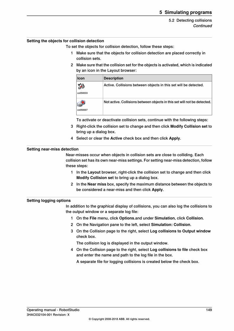
Setting the objects for collision detectionTo set the objects for collision detection, follow these steps:
1 Make sure that the objects for collision detection are placed correctly incollision sets.
2 Make sure that the collision set for the objects is activated, which is indicatedby an icon in the Layout browser:
DescriptionIcon
Active. Collisions between objects in this set will be detected.
xx050033
Not active. Collisions between objects in this set will not be detected.
xx050007
To activate or deactivate collision sets, continue with the following steps:3 Right-click the collision set to change and then click Modify Collision set to
bring up a dialog box.4 Select or clear the Active check box and then click Apply.
Setting near-miss detectionNear-misses occur when objects in collision sets are close to colliding. Eachcollision set has its own near-miss settings. For setting near-miss detection, followthese steps:
1 In the Layout browser, right-click the collision set to change and then clickModify Collision set to bring up a dialog box.
2 In the Near miss box, specify the maximum distance between the objects tobe considered a near-miss and then click Apply.
Setting logging optionsIn addition to the graphical display of collisions, you can also log the collisions tothe output window or a separate log file:
1 On the File menu, click Options.and under Simulation, click Collision.2 On the Navigation pane to the left, select Simulation: Collision.3 On the Collision page to the right, select Log collisions to Output window
check box.The collision log is displayed in the output window.
4 On the Collision page to the right, select Log collisions to file check boxand enter the name and path to the log file in the box.A separate file for logging collisions is created below the check box.
Operating manual - RobotStudio 1493HAC032104-001 Revision: X
© Copyright 2008-2018 ABB. All rights reserved.
5 Simulating programs5.2 Detecting collisions
Continued
5.3 Creating an event
OverviewEvents enhance your simulations by defining actions that are carried out whenspecific trigger conditions are fulfilled. You can use events to:
• Attach one object to another, for example, a work piece to a gripper whensimulating material handling, seeAttaching and detaching objects on page75.
• Set signals, for example, when simulating signals set by equipment otherthan the controller, see Simulating I/O signals on page 151.
• Start or stop the process timer, see Measuring simulation time on page 152.Used for creating new events, the Create New Event Wizard is launched from theEvent manager, see Event Manager on page 359.
PrerequisitesBefore creating the event, make sure that the station contains all signals and objectsthat are planned to be used as triggers or affected by the action.
150 Operating manual - RobotStudio3HAC032104-001 Revision: X
© Copyright 2008-2018 ABB. All rights reserved.
5 Simulating programs5.3 Creating an event

5.4 Simulating I/O signals
ProceduresWhen simulating I/O signals you can either create events that set signal valueswhen specified trigger conditions are fulfilled, or you can set signal values manually.For procedures using the event manager, see Event Manager on page 359.For procedures using the I/O simulator, see I/O Simulator on page 368.
Related informationFor information about controlling I/O signals from the RAPID program, seeCreatingRAPID instructions for setting I/O signals on page 121.
Operating manual - RobotStudio 1513HAC032104-001 Revision: X
© Copyright 2008-2018 ABB. All rights reserved.
5 Simulating programs5.4 Simulating I/O signals
5.5 Measuring simulation time
Stopwatch feature for measuring simulation timeThe Simulation tab's Stopwatch feature is used for measuring the time takenbetween two trigger points in a simulation, and also for the simulation as a whole.The two trigger points are called the Start Trigger and the End Trigger.When a stopwatch is setup, the timer starts when the Start Trigger occurs, andstops when the End Trigger occurs. The kinds of triggers you can specify are:
• Simulation Start• Simulation Stop• Target Changed
Additionally, specify the mechanical Unit and the target.• I/O Value
Additionally, specify the source mechanical unit from where the signal comes,the type of I/O signal and the value of the signal.
You can several stopwatches setup for a simulation. You can also specify a differentname for each stopwatch.For information on how to use the Stopwatch feature, see Stopwatch on page 371
Tip
While you are on the Simulation tab, you can check the RobotStudio status barfor the Simulation Time, that is, from simulation start to simulation stop.
152 Operating manual - RobotStudio3HAC032104-001 Revision: X
© Copyright 2008-2018 ABB. All rights reserved.
5 Simulating programs5.5 Measuring simulation time

6 Working online6.1 Connecting a PC to the controller
GeneralIn general there are two ways of physically connecting a PC to the controller, tothe service port or to the factory network port.
The service portThe service port is intended for service engineers and programmers connectingdirectly to the controller with a PC.The service port is configured with a fixed IP-address, which is the same for allcontrollers and cannot be changed, and has a DHCP server that automaticallyassigns an IP-address to the connected PC.
The factory network portThe factory network port is intended for connecting the controller to a network.The network settings can be configured with any IP-address, typically provided bythe network administrator.
LimitationsThe maximum number of connected network clients using Robot CommunicationRuntime is:
• LAN port: 3• Service port: 1• FlexPendant: 1
The maximum number of applications using Robot Communication Runtime runningon the same PC connected to one controller has no built-in maximum. However,UAS limits the number of logged-on users to 50.The maximum number of concurrently connected FTP clients is 4.
Continues on next pageOperating manual - RobotStudio 1533HAC032104-001 Revision: X
© Copyright 2008-2018 ABB. All rights reserved.
6 Working online6.1 Connecting a PC to the controller
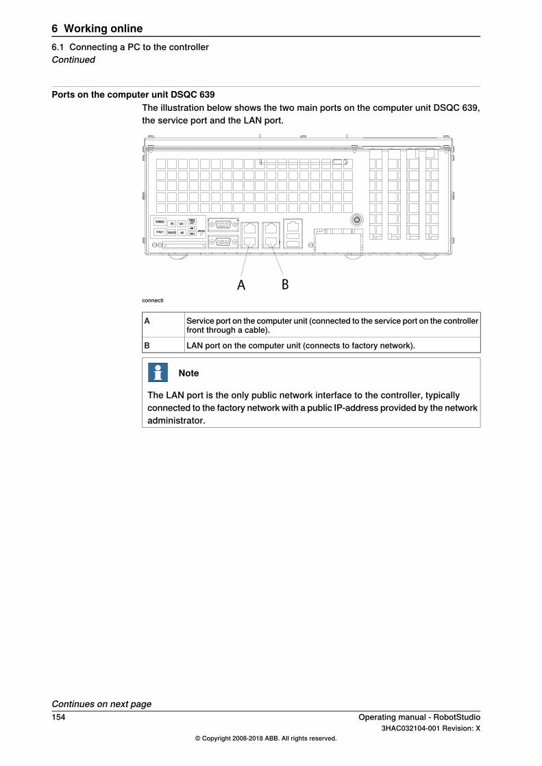
Ports on the computer unit DSQC 639The illustration below shows the two main ports on the computer unit DSQC 639,the service port and the LAN port.
connecti
Service port on the computer unit (connected to the service port on the controllerfront through a cable).
A
LAN port on the computer unit (connects to factory network).B
Note
The LAN port is the only public network interface to the controller, typicallyconnected to the factory network with a public IP-address provided by the networkadministrator.
Continues on next page154 Operating manual - RobotStudio
3HAC032104-001 Revision: X© Copyright 2008-2018 ABB. All rights reserved.
6 Working online6.1 Connecting a PC to the controllerContinued
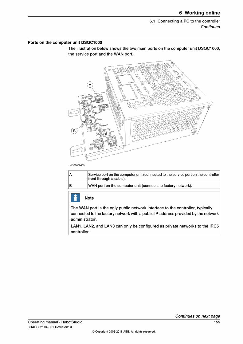
Ports on the computer unit DSQC1000The illustration below shows the two main ports on the computer unit DSQC1000,the service port and the WAN port.
A
B
xx1300000609
Service port on the computer unit (connected to the service port on the controllerfront through a cable).
A
WAN port on the computer unit (connects to factory network).B
Note
The WAN port is the only public network interface to the controller, typicallyconnected to the factory network with a public IP-address provided by the networkadministrator.LAN1, LAN2, and LAN3 can only be configured as private networks to the IRC5controller.
Continues on next pageOperating manual - RobotStudio 1553HAC032104-001 Revision: X
© Copyright 2008-2018 ABB. All rights reserved.
6 Working online6.1 Connecting a PC to the controller
Continued
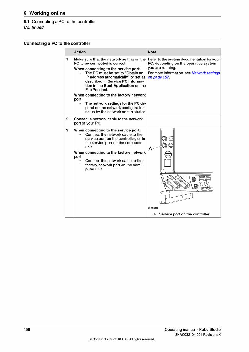
Connecting a PC to the controller
NoteAction
Refer to the system documentation for yourPC, depending on the operative systemyou are running.
Make sure that the network setting on thePC to be connected is correct.When connecting to the service port:
• The PC must be set to “Obtain anIP address automatically” or set asdescribed in Service PC Informa-tion in the Boot Application on theFlexPendant.
When connecting to the factory networkport:
• The network settings for the PC de-pend on the network configurationsetup by the network administrator.
1
For more information, seeNetwork settingson page 157.
Connect a network cable to the networkport of your PC.
2
connectb
A Service port on the controller
When connecting to the service port:• Connect the network cable to the
service port on the controller, or tothe service port on the computerunit.
When connecting to the factory networkport:
• Connect the network cable to thefactory network port on the com-puter unit.
3
156 Operating manual - RobotStudio3HAC032104-001 Revision: X
© Copyright 2008-2018 ABB. All rights reserved.
6 Working online6.1 Connecting a PC to the controllerContinued
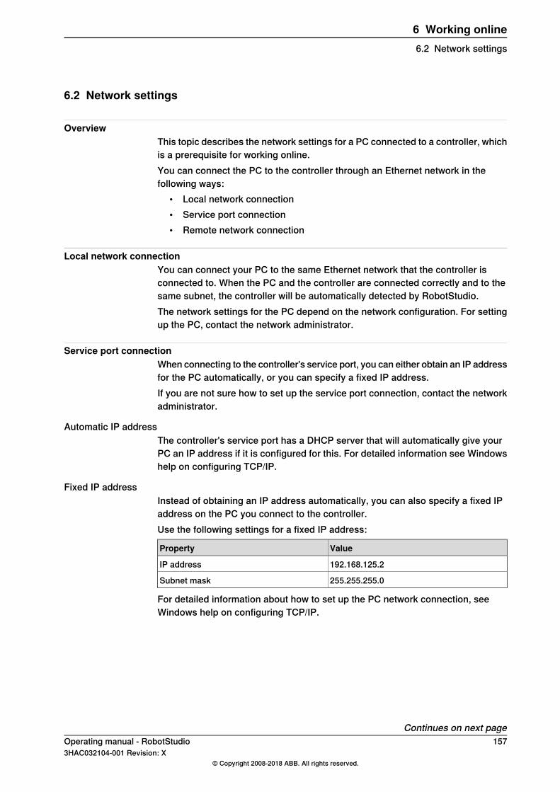
6.2 Network settings
OverviewThis topic describes the network settings for a PC connected to a controller, whichis a prerequisite for working online.You can connect the PC to the controller through an Ethernet network in thefollowing ways:
• Local network connection• Service port connection• Remote network connection
Local network connectionYou can connect your PC to the same Ethernet network that the controller isconnected to. When the PC and the controller are connected correctly and to thesame subnet, the controller will be automatically detected by RobotStudio.The network settings for the PC depend on the network configuration. For settingup the PC, contact the network administrator.
Service port connectionWhen connecting to the controller's service port, you can either obtain an IP addressfor the PC automatically, or you can specify a fixed IP address.If you are not sure how to set up the service port connection, contact the networkadministrator.
Automatic IP addressThe controller's service port has a DHCP server that will automatically give yourPC an IP address if it is configured for this. For detailed information see Windowshelp on configuring TCP/IP.
Fixed IP addressInstead of obtaining an IP address automatically, you can also specify a fixed IPaddress on the PC you connect to the controller.Use the following settings for a fixed IP address:
ValueProperty
192.168.125.2IP address
255.255.255.0Subnet mask
For detailed information about how to set up the PC network connection, seeWindows help on configuring TCP/IP.
Continues on next pageOperating manual - RobotStudio 1573HAC032104-001 Revision: X
© Copyright 2008-2018 ABB. All rights reserved.
6 Working online6.2 Network settings
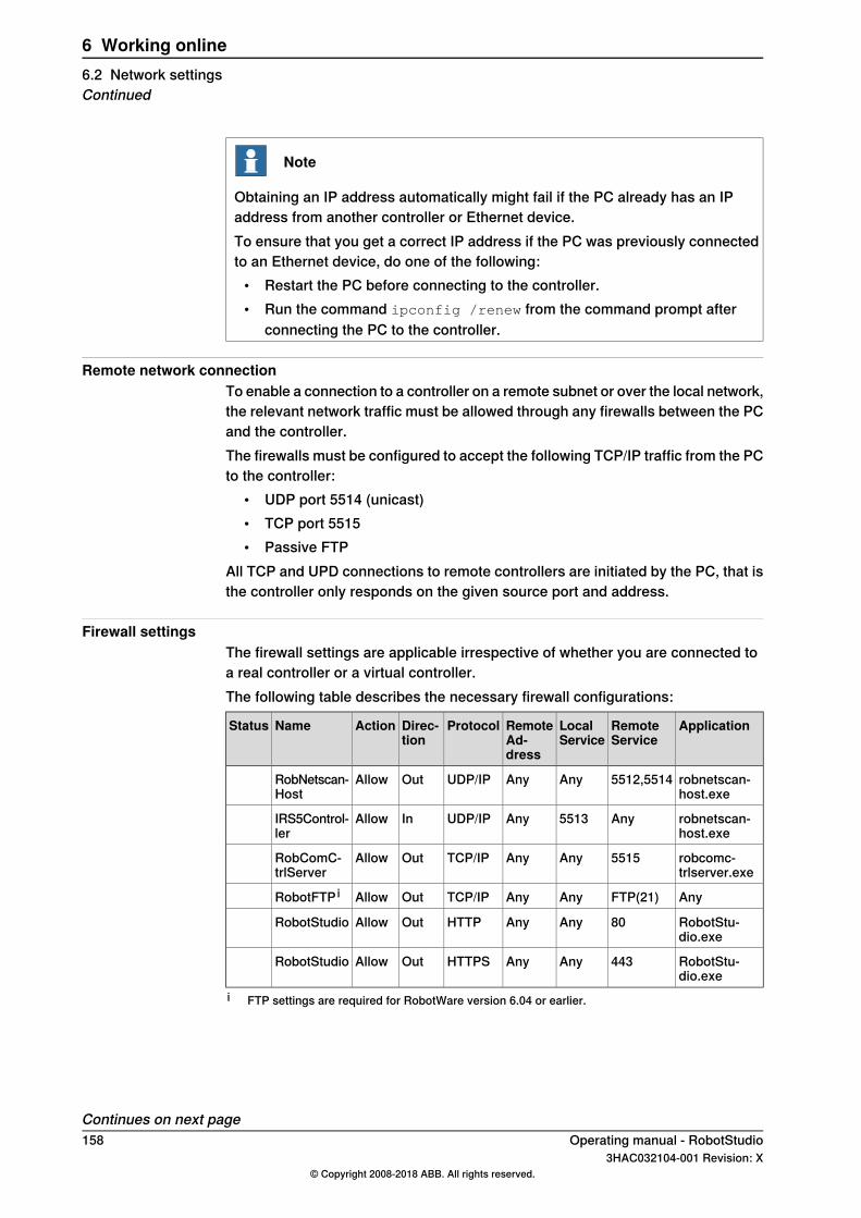
Note
Obtaining an IP address automatically might fail if the PC already has an IPaddress from another controller or Ethernet device.To ensure that you get a correct IP address if the PC was previously connectedto an Ethernet device, do one of the following:
• Restart the PC before connecting to the controller.• Run the command ipconfig /renew from the command prompt after
connecting the PC to the controller.
Remote network connectionTo enable a connection to a controller on a remote subnet or over the local network,the relevant network traffic must be allowed through any firewalls between the PCand the controller.The firewalls must be configured to accept the following TCP/IP traffic from the PCto the controller:
• UDP port 5514 (unicast)• TCP port 5515• Passive FTP
All TCP and UPD connections to remote controllers are initiated by the PC, that isthe controller only responds on the given source port and address.
Firewall settingsThe firewall settings are applicable irrespective of whether you are connected toa real controller or a virtual controller.The following table describes the necessary firewall configurations:
ApplicationRemoteService
LocalService
RemoteAd-dress
ProtocolDirec-tion
ActionNameStatus
robnetscan-host.exe
5512,5514AnyAnyUDP/IPOutAllowRobNetscan-Host
robnetscan-host.exe
Any5513AnyUDP/IPInAllowIRS5Control-ler
robcomc-trlserver.exe
5515AnyAnyTCP/IPOutAllowRobComC-trlServer
AnyFTP(21)AnyAnyTCP/IPOutAllowRobotFTP i
RobotStu-dio.exe
80AnyAnyHTTPOutAllowRobotStudio
RobotStu-dio.exe
443AnyAnyHTTPSOutAllowRobotStudio
i FTP settings are required for RobotWare version 6.04 or earlier.
Continues on next page158 Operating manual - RobotStudio
3HAC032104-001 Revision: X© Copyright 2008-2018 ABB. All rights reserved.
6 Working online6.2 Network settingsContinued

Note
Port 443 is not required for controller communication, but it is required for externalcommunication with ABB for availing services like upgrade notifications andonline services.
In addition, the following table describes the necessary firewall configurations forthe RobotWare option, Integrated Vision:
ApplicationRemoteService
LocalService
RemoteAd-dress
ProtocolDirec-tion
ActionNameStatus
RobotStu-dio.exe
23AnyAnyTCP/IPOutAllowTelnet
RobotStu-dio.exe
1069AnyAnyTCP/IPOutAllowIn-Sight Pro-tocol
RobotStu-dio.exe
10691069AnyUDP/IPIn/OutAllowIn-Sight Dis-covery
RobotStu-dio.exe
1212AnyAnyTCP/IPOutAllowUpgrade port(PC only)
RobotStu-dio.exe
50000AnyAnyTCP/IPOutAllowDataChannel
Note
RobotStudio uses the current Internet Options, HTTP, and proxy settings to getthe latest RobotStudio news. To view the latest RobotStudio news, go to the Filetab and then the Help sub-tab.
Connecting to the controller1 Make sure the PC is connected to the controller's service port and that the
controller is running.2 On the File menu, click Online and then select One Click Connect.
This takes you to the Controller tab.3 Click Add Controller4 Click Request Write access.
ThenIf the controller is in mode
You will now get Write Access if it is available.Auto
A message box on the FlexPendant will allow you togrant remote Write Access to RobotStudio.
Manual
Operating manual - RobotStudio 1593HAC032104-001 Revision: X
© Copyright 2008-2018 ABB. All rights reserved.
6 Working online6.2 Network settings
Continued

6.3 User Authorization
OverviewThis section describes the controller's User Authorization System (UAS), whichrestricts what different users are allowed to do with the robot. This is for protectingdata and functionality from unauthorized use.The user authorization is managed by the controller, which means that the UASsettings remain for the controller regardless of which system it is running. It alsomeans that the UAS settings apply to all tools for communicating with the controller,like RobotStudio or the FlexPendant. The UAS settings defines the users andgroups that can access the controller, and what actions they are granted accessto.For procedures, see User Accounts on page 430.
UsersUAS users are accounts with which persons log on to the controller. Furthermore,the users are added to groups to which access grants are given. The maximumnumber of configured users is 100.The users are defined in the controller by a user name and a password. For loggingon to a controller, the user must type in a defined user name with a correctpassword. The maximum allowed characters for user name and password is 16.A user can either have the state activated or deactivated in the UAS. When a useris deactivated it is not possible to log on to the controller using that account. It isthe UAS administrator that activates and deactivates the users.
The Default userAll controllers have a default user named Default User with a publicly knownpassword robotics. TheDefault User cannot be removed and the password cannotbe changed. However, a user having the grant Manage UAS settings can modifyand restrict the controller grants and application grants of the Default User.
Note
From RobotWare 6.04 it is also possible to deactivate the Default User, see UserAccounts on page 430.
GroupsIn UAS, groups are defined sets of grants for accessing the controller. To thegroups you then add the users who shall have the grants defined by the group.A good practice is to create groups that resembles the professions that work withthe robots in your organization. For example, you can create groups for
Continues on next page160 Operating manual - RobotStudio
3HAC032104-001 Revision: X© Copyright 2008-2018 ABB. All rights reserved.
6 Working online6.3 User Authorization
administrators, programmers and operators. The maximum allowed characters fora group name is 16. The maximum number of groups that can be created is 20.
The Default groupAll controllers have a default group named Default Group, to which all grants aregiven and to which the default user belongs. This group cannot be removed, butit can be changed by the user having the grant Manage UAS settings.
Note
There is a risk changing the group membership of the default user. If you bymistake clear the Default User check box or any Default Group grant, you willget a warning. Make sure that there is at least one user defined that has the grantManage UAS settings. If the Default group and no other group have the grantManage UAS settings, you may lose your ability to manage users and groups.
GrantsGrants are permissions to perform actions or access data on the controller. Youuse the grants by giving them to groups, to which you then add the users who shallhave the grants.Grants may be either controller grants or application grants. Depending on theactions that you will perform, you may need several grants. For procedures, seeUAS Grant Viewer on page 435.
Controller grantsController grants are validated by the robot controller and apply to all tools anddevices accessing the controller.
Application grantsApplication grants are used by a specific application, for example the FlexPendant,and will only be valid using that application. Application grants can be added byadd-ins and used in customer applications.
Local and remote clientsRobotStudio normally acts as a remote client of the controller and a deviceconnected to the FlexPendant connector on the controller acts as a local client.The privileges of a remote client is restricted when the controller is in manual modewhen compared to a local client, for example, a remote client cannot start programexecution or set the program pointer.
RobotStudio as local clientRobotStudio can act as a local client thereby can get full access to the controllerfunctionality without restrictions in manual mode. When you select the local clientcheckbox in the Add controller dialog or in the Login dialog you can get localclient privileges by pressing the enabling switch on the safety device twice, forexample, the FlexPendant, JSHD4, or the T10.
Operating manual - RobotStudio 1613HAC032104-001 Revision: X
© Copyright 2008-2018 ABB. All rights reserved.
6 Working online6.3 User Authorization
Continued
6.4 The System Builder
6.4.1 About System Builder
OverviewThis section describes how you create, build, modify and copy systems to run onvirtual and real controllers. These systems may even be converted to boot mediaand downloaded to a real controller.The system points out the robot models and options to use; it also storesconfigurations and programs for the robots. Therefore, it is good practice to usea unique system for each station even if the stations use the same basic setup.Otherwise, changes in one station may accidently overwrite data used in anotherstation.
Note
Use System Builder to create and modify systems based on RobotWare 5.xx.Use Installation Manager to create and modify systems with RobotWare versions6.0 and later, see The Installation Manager on page 181.
About virtual and real systemsThe system you run on virtual controllers can either be a real system built on realRobotWare keys or a virtual system built on virtual keys.When using real systems, the RobotWare keys define which options and robotmodels shall be used, thus helping you to configure the system correctly. Realsystems can be run both on virtual controllers and real IRC5 controllers.When using virtual keys, all options and robot models are available, which is usefulfor evaluation purposes, but requires more configuration when creating the system.Systems built on virtual keys can only be run on virtual controllers.
PrerequisitesCreating a system entails applying a predefined template to a station, reusing anexisting system or letting RobotStudio propose a system based on a layout.To create a system, the following conditions must be met:
• The RobotWare media pool must be installed on your PC.• You must have a RobotWare key for the system, if creating a system to run
on a real controller. The RobotWare key is a license key that determineswhich robot models to use and which RobotWare options to run on thecontroller. The license key is delivered with the controller.
• If you want to create a system for virtual use only, you can use a virtual keyinstead. Virtual keys are generated by the wizard. When using virtual keys,you select the robot models and options to use in theModify Options sectionof the wizard.
• Downloading to the real controller requires a direct connection from yourcomputer to the service or Ethernet port of the controller.
Continues on next page162 Operating manual - RobotStudio
3HAC032104-001 Revision: X© Copyright 2008-2018 ABB. All rights reserved.
6 Working online6.4.1 About System Builder

Administering systemsSystems can be administered from the System Builder dialog box in the followingways:
• View system properties, see Viewing system properties on page 164.• Build a system, see Building a new system on page 165.• Modify or delete a system, see Modifying a system on page 169.• Copy a system, see Copying a system on page 173.• Create a system from backup, seeCreating a system frombackup on page174.• Download a system to a controller, seeDownloading a system to a controller
on page 175.• Create boot media, see Creating boot media on page 176.
Operating manual - RobotStudio 1633HAC032104-001 Revision: X
© Copyright 2008-2018 ABB. All rights reserved.
6 Working online6.4.1 About System Builder
Continued
6.4.2 Viewing system properties
OverviewAll systems you create with the System Builder are stored locally on your computer.It is recommended that you store them in one or more dedicated system directories.
Viewing system propertiesTo view system properties and add comments, follow these steps:
1 In the System Builder dialog box, select a system from the Systems box.If necessary, in the System directory list, you can navigate to the folder inwhich your systems are stored
2 The system properties are then displayed in the System Properties box.Optionally, type a comment in the Comments box, and click Save.
164 Operating manual - RobotStudio3HAC032104-001 Revision: X
© Copyright 2008-2018 ABB. All rights reserved.
6 Working online6.4.2 Viewing system properties

6.4.3 Building a new system
OverviewThe New Controller System Wizard, used for building a new system, is launchedfrom the System Builder.
Starting the wizardTo start the wizard, follow these steps:
1 Click System Builder to bring up a dialog box.2 In the Actions group, click Create New. This starts the wizard.3 Read the information on the welcome page and click Next.
Specifying the name and locationTo determine where on your computer to store the system you are creating, followthese steps:
1 In the Name box, enter a name for the system you are creating.2 In the Path box, enter the path to the system directory in which you will store
the system.You can also click the Browse button and browse to the system directory.
3 Click Next.
Entering the RobotWare keysThe RobotWare keys determine which RobotWare versions and parts to use in thesystem.Creating a system to run on either IRC5 controllers or virtual controllers requiresat least two keys: one for the controller module and one for each drive module inthe cabinet. The keys are delivered together with the controller.For creating a system to run on virtual controller only (for example, in Virtual IRC5),you can use virtual keys. Virtual keys give access to all options and robot models,but limits the use of the system to virtual controllers only.To enter the key for the controller module, follow these steps:
1 In theController Key box, enter the controller key. You can also clickBrowseand browse to the key file. If creating a system for virtual use only, selectthe Virtual Key check box, and the controller key will be generated by thewizard.
2 In the Media Pool box, enter the path to the media pool. You can also clickBrowse and browse to the folder.system
3 In the RobotWare Version list, select which version of the RobotWare youwant to use. Only RobotWare versions that are valid for the used key areavailable.
4 Click Next.
Continues on next pageOperating manual - RobotStudio 1653HAC032104-001 Revision: X
© Copyright 2008-2018 ABB. All rights reserved.
6 Working online6.4.3 Building a new system
Entering the drive keysTo enter the keys for the drive modules:
1 In the Drive Key box, enter the key for the drive module. You can also clickthe Browse button and browse to the key file. If you used a virtual controllerkey, a virtual drive key is already generated by the wizard.
2 Click the right arrow button next to the Drive Key box. The key now appearsin the Added drive keys list.For real systems the drive key determines the connected robot model. Forvirtual systems you select the robot model in the Modify Options page. Thedefault model is IRB140.
3 If you have a MultiMove system, repeat steps 1 and 2 for each drive key toadd.If you have a MultiMove system, make sure that the keys are numbered inthe same way as their corresponding drive modules are connected to thecontroller module. Use the up and down arrows to rearrange the drive keys,if necessary.
4 If you want to create the system as it is now, click Finish.If you want to modify options, or add options, parameter data or additionalfiles to the home directory, click Next.
Adding additional optionsHere you can add options, such as external axes and dispense applications, thatare not included in the basic system. Options require a license key and must befirst imported to the media pool. To add additional options, follow these steps:
1 In the Key box, enter the option key. You can also click the Browse buttonand browse to the option's key file.
2 Click the Arrow button.The option that the key unlocks is now displayed in the Added Options list.
Note
If several versions of an additional option exists, only the latest versioncan be selected. To use an older version, remove the other versions of theadditional option from the Mediapool.System Builder can modify a system only when all referenced additionaloptions and RobotWare mediapool are placed in the same folder. It is notpossible to modify a system that uses a mediapool embedded in a Packand Go file. You must copy the mediapool to a common mediapool folderand create a system from backup.
3 Repeat steps 1 and 2 for all options you want to include.4 Choose whether you want to create the system as it is now, or to continue
with the wizard.If you want to create the system as it is now, click Finish.
Continues on next page166 Operating manual - RobotStudio
3HAC032104-001 Revision: X© Copyright 2008-2018 ABB. All rights reserved.
6 Working online6.4.3 Building a new systemContinued
If you want to modify options, or add parameter data or additional files to thehome directory, click Next.
Modifying optionsHere you can set up and configure the options in your system. For virtual systems,you also select the robot models to use. To modify any options, follow these steps:
1 In the Option tree, expand the option folders to the level where you find theoption you want to modify.Only the options unlocked by the used keys are available.
2 Modify the option.3 Repeat steps 1 and 2 for all options you want to modify.4 Choose whether you want to create the system as it is now, or to continue
with the wizard.If you want to create the system as it is now, click Finish.If you want to add parameter data or additional files to the home directory,click Next.
Adding parameter dataParameter data is stored in the parameter data files (.cfg files). Each parametertopic has its own parameter file. You can add only one parameter file for each topic.To add parameter data, follow these steps:
1 In the Parameter data box, enter the path to the folder for the parameter datafiles. You can also click the Browse button and browse to the folder.
2 In the list of parameter data files, select the file you want to include and pressthe Arrow button. Repeat for all files you want to include.The included parameter data files will now appear in the Added parameterdata files list.Repeat steps 1 and 2 for each parameter data file you want to add.
3 Choose whether you want to create the system as it is now, or to continuewith the wizard.If you want to create the system as it is now, click Finish.If you want to add additional files to the home directory, click Next.
Adding files to the home directoryYou can add any type of file to the system’s home directory. When the system isloaded to a controller, these files will also be loaded. To add files to the system'shome directory, follow these steps:
1 In the Files box, enter the path to the folder for the files you want to include.You can also click the Browse button and browse to the folder.
2 In the list of files, select the file to add and click the Arrow button. Repeatfor all files you want to add.The added files will now appear in the Added files list.
3 Choose whether you want to create the system as it is now, or to continuewith the wizard.
Continues on next pageOperating manual - RobotStudio 1673HAC032104-001 Revision: X
© Copyright 2008-2018 ABB. All rights reserved.
6 Working online6.4.3 Building a new system
Continued
If you want to create the system as it is now, click Finish.If you want to read a summary before you create the system, click Next.
Completing the New Controller System WizardTo complete the wizard, follow these steps:
1 Read the system summary.2 If the system is OK, click Finish.
If the system is not OK, click Back and make modifications or corrections.
168 Operating manual - RobotStudio3HAC032104-001 Revision: X
© Copyright 2008-2018 ABB. All rights reserved.
6 Working online6.4.3 Building a new systemContinued
6.4.4 Modifying a system
OverviewTheModify Controller SystemWizard, used to modify existing systems, is launchedfrom the System Builder.The wizard helps you with tasks like changing robots,adding and removing external axes and other options. A system that is runningmust be first shut down before modification.
Starting the wizardTo start the wizard when creating a new station:
1 If the system is currently running, on theControllermenu, point to Shutdownand then click Shutdown.
2 On the Controller menu, click System Builder to bring up a dialog box.3 In the System directory list, enter or browse to the system directory. Select
a system from the list beneath, review the system properties and add andsave any comments.
4 In the Actions group, click Modify. This starts the wizard.5 Read the information on the welcome page and click Next.
Modifying the program revisionThe RobotWare versions that are available for the system are determined by thecontroller key. The key is essential to the system and cannot be modified.To use another RobotWare version than the available ones, create a new systemwith another key.To optionally modify the program revision, follow the appropriate step or steps:
1 To keep the current RobotWare version, select Yes and then click Next .2 To replace the current RobotWare version, Select No, replace it..3 In the Media pool box, enter the path to the media pool. You can also click
the Browse button and browse to the folder.4 In the New program revision box, select which version of RobotWare you
want to use. Only RobotWare versions that are valid for the RobotWare keyare available.
5 Click Next.
Adding or removing drive keysThe drive key corresponds to the drive modules in your controller. For MultiMovesystems, you have one drive module (and one key) for each robot. The keys foryour system are delivered together with the controller.the system is created with a vritual controller key, virtual drive keys are generatedby the wizard. when you have added one virtual drive key for each robot, you selectwhich robot to use for each key on the Modify Options page.To optionally add or remove the keys for the drive modules, follow these steps:
1 To add a key for a drive module, enter the key in the Enter Drive Key box.You can also click the Browse button and browse to the key file.
Continues on next pageOperating manual - RobotStudio 1693HAC032104-001 Revision: X
© Copyright 2008-2018 ABB. All rights reserved.
6 Working online6.4.4 Modifying a system
2 Click the right arrow button. The key now appears in the Added drive keylist.If you have a MultiMove system, repeat steps 1 and 2 for each drive key toadd.
3 To remove a drive module, select the corresponding key in the Added drivekey list and click Remove drive key.If you have a MultiMove system, repeat step 3 for each drive key to remove.
4 If you have a MultiMove system, make sure that the keys are numbered inthe same way as their corresponding drive modules are connected to thecontroller module. Use the up and down arrows to rearrange the drive keys,if necessary.
5 Choose whether you want to create the system as it is now, or to continuewith the wizard.If you want to create the system as it is now, click Finish.If you want to modify options, parameter data or add files to or remove filesfrom the home directory, click Next.
Adding or removing additional optionsTo optionally add or remove additional options:
1 To add an add-in, in the Enter Key box, enter the option key. You can alsoclick the Browse button and browse to the option's key file.
2 Click the Arrow button.The option that the key unlocks is now displayed in the Added Options list.
Note
If several versions of an additional option exists, only the latest versioncan be selected. To use an older version, remove the other versions of theadditional option from the Mediapool.
3 Repeat steps 1 and 2 for all options you want to include.4 To remove an add-in, In the additional options, in the Added options list,
select the add-in you want to remove.5 Click Remove.6 Choose whether you want to create the system as it is now, or to continue
with the wizard.If you want to create the system as it is now, click Finish.If you want to modify parameter data or add files to or remove files from thehome directory, click Next.
Modifying optionsTo optionally modify any options, follow these steps:
1 In the Option tree, expand the option folders to the level where you find theoption you want to modify.Only the options unlocked by the used keys are available.
Continues on next page170 Operating manual - RobotStudio
3HAC032104-001 Revision: X© Copyright 2008-2018 ABB. All rights reserved.
6 Working online6.4.4 Modifying a systemContinued
2 Modify the option.3 Repeat steps 1 and 2 for all options you want to modify.4 Choose whether you want to create the system as it is now, or to continue
with the wizard.If you want to create the system as it is now, click Finish.If you want to modify parameter data or add files to or remove files from thehome directory, click Next.
Adding or removing parameter dataParameter data is stored in the parameter data files (.cfg files). each parametertopic has its own parameter file. You can add only one parameter file for each topic.To addor remove parameter data, follow these steps:
1 To add parameter data, in the Parameter data box, enter the path to thefolder for the parameter data files. You can also click the Browse button andbrowse to the folder.
2 In the list of parameter data files, select the file you want to include and pressthe Arrow button. Repeat for all files you want to include.The included parameter data files will now appear in the Added parameterdata files list.Repeat steps 1 and 2 for each parameter data file you want to add.
3 To remove parameter data, in the Added parameter data files list, select theparameter data file to remove.
4 Click Remove.5 Choose whether you want to create the system as it is now, or to continue
with the wizard.If you want to create the system as it is now, click Finish.If you want to add to or remove files from the home directory, click Next.
Add files to or remove files from the home directoryYou can add any type of file to the system’s home directory, or remove files fromit. When the system is loaded to a controller, these files will also be loaded. Tooptionally add files to or remove files from the system's home directory, followthese steps:
1 To add files, in the Files box, enter the path to the folder for the files youwant to include. You can also click the Browse button and browse to thefolder.
2 In the list of files, select the file to add and click the Arrow button. Repeatfor all files you want to add.The added files will now appear in the Added files list.
3 To remove files, in the Added files list, select the file to remove.4 Click Remove.5 Choose whether you want to create the system as it is now, or to continue
with the wizard.If you want to create the system as it is now, click Finish.
Continues on next pageOperating manual - RobotStudio 1713HAC032104-001 Revision: X
© Copyright 2008-2018 ABB. All rights reserved.
6 Working online6.4.4 Modifying a system
Continued
If you want to read a summary before you create the system, click Next.
Complete the Modify Controller System wizardTo complete the wizard, follow these steps:
1 Read the system summary.2 If the system is OK, click Finish.
If the system is not OK, click Back and make modifications or corrections.
ResultModifications will take effect when the wizard is completed.If the system has been downloaded to a controller, it must be downloaded againbefore the modifications will take effect on the controller.If the system is used by a VC, restart the controller using the restart mode Resetcontroller for the changes to take effect.
Deleting a systemTo delete a system, follow this steps:
1 From the SystemBuilder dialog box, select the system and then clickDelete.
172 Operating manual - RobotStudio3HAC032104-001 Revision: X
© Copyright 2008-2018 ABB. All rights reserved.
6 Working online6.4.4 Modifying a systemContinued
6.4.5 Copying a system
Copy a systemTo copy a system, follow these steps:
1 From the System Builder dialog box, select the system and then click Copyto bring up a dialog box.
2 Enter a name for the new system and a path, and then click OK.
Operating manual - RobotStudio 1733HAC032104-001 Revision: X
© Copyright 2008-2018 ABB. All rights reserved.
6 Working online6.4.5 Copying a system
6.4.6 Creating a system from backup
OverviewThe Create System from Backup Wizard, which creates a new system from acontroller system backup, is launched form the System Builder. In addition, youcan change the program revision and options.
Starting the wizardTo start the wizard, follow these steps:
1 From the System Builder dialog box, click Create from Backup. This startsthe wizard.
2 Read the information on the welcome page and click Next.
Specifying the name and locationTo specify the destination folder, follow these steps:
1 In the Name box, enter a name for the system you are creating.2 In the Path box, enter the path to the system directory in which you will store
the system.You can also click the Browse button and browse to the system directory.
3 Click Next.
Locating the backupTo locate a system from backup, follow these steps:
1 In the Backup folder box, enter the path to the backup folder. Alternatively,click the Browse button to browse to it. Click Next.
2 In the Media Pool box, enter the path to the media pool containing theappropriate RobotWare program. Confirm the backup information that nowappears in the wizard. Click Next.
174 Operating manual - RobotStudio3HAC032104-001 Revision: X
© Copyright 2008-2018 ABB. All rights reserved.
6 Working online6.4.6 Creating a system from backup
6.4.7 Downloading a system to a controller
OverviewAll systems you access from the System Builder are stored on your computer. Ifyou wish to run a system on a robot controller, you must first load it to the controller,which then requires a restart.
Load a systemTo load a system to a controller, follow these steps:
1 From the System Builder dialog box, select a system and then clickDownloadto Controller to bring up a dialog box.
Note
Systems with incompatible hardware versions will not be displayed in theDownload to Controller dialog box.
2 Specify the Destination Controller for the system.
if...You can select by using the...
the controller has been detected automat-ically.
Select controller from list option
your PC and the robot is connected to thesame network.
Specify IP address or controller nameoption
You can only use the controller name inDHCP networks.
your PC is directly connected to the con-troller's service port.
Use service port option
3 Optionally, click Test Connection to confirm that the connection betweenthe computer and the Controller is OK.
4 Click Load.5 Answer Yes to the question Do you want to restart the controller now?
The controller restarts immediately and the downloaded systemstarts automatically.
Yes
The controller does not restart immediately.NoTo start using the downloaded system, you have to:
a Restart the controller using the restart mode Start Boot Ap-plication.
b select the system manually
The downloaded system is removed from the controller.Cancel
Operating manual - RobotStudio 1753HAC032104-001 Revision: X
© Copyright 2008-2018 ABB. All rights reserved.
6 Working online6.4.7 Downloading a system to a controller

6.4.8 Creating boot media
OverviewBoot media is an entire system which the System Builder packs to a single file andcommonly stores on a hard disk or USB memory. The controller then accessesthe file through its Ethernet port or USB port, respectively.
Creating boot mediaTo create boot media, follow these steps:
1 From the System Builder dialog box, create a new system. For creating anew system, see Building a new system on page 165.
2 From the System Builder dialog box, select a new system or an existingsystem and then click Boot Media.
3 In the Path box, enter the path to the folder where you want to store the bootmedia file. Alternatively, browse to the location.
4 Click OK.
ResultTo load the boot media system to a controller, first connect it and then restart thecontroller using the restart mode Start Boot Application.
176 Operating manual - RobotStudio3HAC032104-001 Revision: X
© Copyright 2008-2018 ABB. All rights reserved.
6 Working online6.4.8 Creating boot media
6.4.9 Examples using the System Builder when offline
6.4.9.1 A system with support for one robot and one positioner external axis
OverviewIn this example we will use the System Builder to create an offline system to usein a new RobotStudio station with one IRB1600 robot and one IRBP 250D positionerexternal axis.
PrerequisitesWhen creating systems for positioner external axes, you need the media pool andthe license key file for that specific positioner. In this example we will use a mediapool and license key file for a demo positioner.Paths to files and folders assume that RobotStudio and the RobotWare media poolhave been installed at their default locations on Windows XP. If not, adjust thepaths accordingly.
Starting the New Controller System WizardTo create a system like the one described above, follow these steps:
1 Click System Builder to bring up a dialog box.2 In the dialog box, click Create New to bring up the New Controller System
Wizard.3 Read the welcome text, and click Next to continue to the next page.
Entering the controller key1 Select the Virtual key check box. A virtual controller key now appears in the
Controller Key box. In this example we will use the default media pool andRobotWare version.
2 Click Next to continue to the next page.
Entering drive keys1 Click the Right Arrow button next to the Enter Drive key box to create one
drive key for the robot.2 Click Next to continue to the next page.
Adding optionsThis is where we point out the key file for the positioner.
1 Next to the Enter key box, click the browse button and select the key file.
Continues on next pageOperating manual - RobotStudio 1773HAC032104-001 Revision: X
© Copyright 2008-2018 ABB. All rights reserved.
6 Working online6.4.9.1 A system with support for one robot and one positioner external axis

In this example, browse to and select the file extkey.kxt in the folderC:\Program Files\ABB Industrial IT\RoboticsIT\MediaPool\3HEA-000-00022.01.
Tip
In the MediaPool folder media pools for several standard positioners areinstalled. They are named by the positioner’s article number, with a suffixthat indicates if it is configured for single-robot or MultiMove systems.
2 Click the Right Arrow button next to the Enter key box to add the key for thepositioner.
3 Click Next and continue to the next page of the wizard.
Modifying optionsWhen creating robot systems from real robot keys, the key sets the options. Butsince we are using a virtual key, we have to set the options manually. To set theoptions necessary for a positioner, follow these steps:
1 Scroll down to the RobotWare / Hardware group and select the 709-xDeviceNet check box.This option is for the communication between the controller and the trackexternal axis.
2 Scroll down to the DriveModule1 / Drive module application group andexpand the ABB Standard manipulator option. Select the IRB 1600 option.This option sets the robot to an IRB 1600-5/1.2.
3 Scroll down to theDriveModule1 > Drivemodule configuration group; selectthe Drive System 04 1600/2400/260 option; expand the Additional axesdrive module group and select the R2C2 Add drive option.
a Expand the Drive type in position Z4 group and select the 753-1 DriveC in pos Z4 option
b Expand the Drive type in position Y4 group and select the754-1 DriveC in pos Y4 option
c Expand the Drive type in position X4 group and select the755-1 DriveC in pos X4 option
Continues on next page178 Operating manual - RobotStudio
3HAC032104-001 Revision: X© Copyright 2008-2018 ABB. All rights reserved.
6 Working online6.4.9.1 A system with support for one robot and one positioner external axisContinued
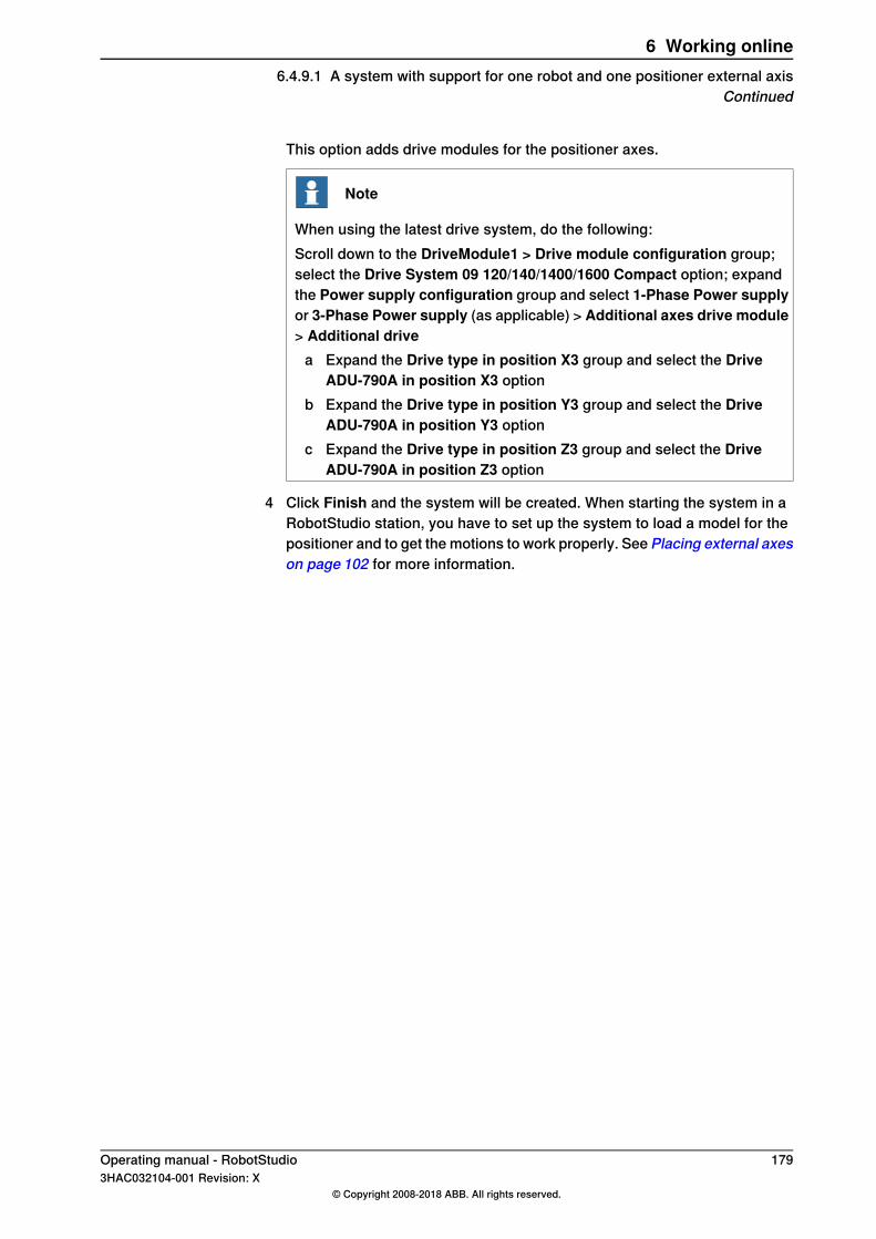
This option adds drive modules for the positioner axes.
Note
When using the latest drive system, do the following:Scroll down to the DriveModule1 > Drive module configuration group;select the Drive System 09 120/140/1400/1600 Compact option; expandthe Power supply configuration group and select 1-Phase Power supplyor 3-Phase Power supply (as applicable) > Additional axes drive module> Additional drive
a Expand the Drive type in position X3 group and select the DriveADU-790A in position X3 option
b Expand the Drive type in position Y3 group and select the DriveADU-790A in position Y3 option
c Expand the Drive type in position Z3 group and select the DriveADU-790A in position Z3 option
4 Click Finish and the system will be created. When starting the system in aRobotStudio station, you have to set up the system to load a model for thepositioner and to get the motions to work properly. See Placing external axeson page 102 for more information.
Operating manual - RobotStudio 1793HAC032104-001 Revision: X
© Copyright 2008-2018 ABB. All rights reserved.
6 Working online6.4.9.1 A system with support for one robot and one positioner external axis
Continued

6.4.9.2 Options settings for systems with positioners
OverviewThis is an overview of the RobotWare options to set when creating a system forpositioner external axes. Note that besides setting the RobotWare options, youmust add an additonal option key for the positioner.
Media pools and option keys for the positionersIf you have the media pool and option key for your positioner, you can use thesefiles.If not, media pools for standard positioners are installed with RobotStudio. Thepath to these media pools in a default installation is:C.\program files\ABB IndustrialIT\Robotics IT\MediaPool. In this folder a media pool for each positioner is located.These are named by the article number of the positioner, with a suffix that indicatesif it is configured for a single-robot or a MultiMove system.In the Additional option page of the System Builder, you should add the optionfor the positioner by opening the mediapool folder for the positioner to add andselecting the extkey.kxt file.
Options for positioners in single-robot systemsWhen adding a positioner to a single-robot system, the positioner will be added tothe same task as the robot. Below, the options to set on the Modify Options pageof the System Builder for such a system are listed:
• RobotWare > Hardware > 709-x DeviceNet > 709-1 Master/Slave Single• Optionally, for using the system with ArcWare also add RobotWare >
Application arc > 633-1 Arc• DriveModule 1 > Drive module configuration > Drive System 04
1600/2400/260 > RC2C Add drive > 753-1 Drive C in pos Z4 > 754-2 DriveT in pos Y4 > 755-3 Drive U in pos X4
Options for positioners in MultiMove robot systemsWhen adding a positioner to a MultiMove robot system, the positioner shall beadded to a task of its own (thus you also have to add a drive key for the positioner).Below, the options to set on the Modify Options page of the System Builder forsuch a system are listed:
• RobotWare > Hardware > 709-x DeviceNet > 709-1 Master/Slave Single• RobotWare > Motion coordinated part 1 > 604-1 MultiMove Coordinated
Optionally, expand the MultiMove Coordinated option and select processoptions for the robots.
• Optionally, for using the system with ArcWare, addRobotWare >ApplicationArc > 633-1 Arc
• DriveModule 1 > Drive module configuration > Drive System 041600/2400/260 > RC2C Add drive > 753-1 Drive C in pos Z4 > 754-2 DriveT in pos Y4 > 755-3 Drive U in pos X4. For the other drive modules, noadditional axes should be configured.
180 Operating manual - RobotStudio3HAC032104-001 Revision: X
© Copyright 2008-2018 ABB. All rights reserved.
6 Working online6.4.9.2 Options settings for systems with positioners
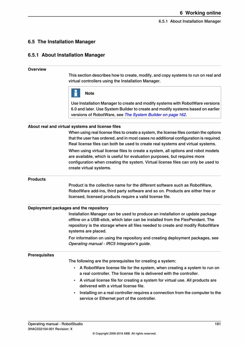
6.5 The Installation Manager
6.5.1 About Installation Manager
OverviewThis section describes how to create, modify, and copy systems to run on real andvirtual controllers using the Installation Manager.
Note
Use Installation Manager to create and modify systems with RobotWare versions6.0 and later. Use System Builder to create and modify systems based on earlierversions of RobotWare, see The System Builder on page 162.
About real and virtual systems and license filesWhen using real license files to create a system, the license files contain the optionsthat the user has ordered, and in most cases no additional configuration is required.Real license files can both be used to create real systems and virtual systems.When using virtual license files to create a system, all options and robot modelsare available, which is useful for evaluation purposes, but requires moreconfiguration when creating the system. Virtual license files can only be used tocreate virtual systems.
ProductsProduct is the collective name for the different software such as RobotWare,RobotWare add-ins, third party software and so on. Products are either free orlicensed, licensed products require a valid license file.
Deployment packages and the repositoryInstallation Manager can be used to produce an installation or update packageoffline on a USB-stick, which later can be installed from the FlexPendant. Therepository is the storage where all files needed to create and modify RobotWaresystems are placed.For information on using the repository and creating deployment packages, seeOperating manual - IRC5 Integrator's guide.
PrerequisitesThe following are the prerequisites for creating a system:
• A RobotWare license file for the system, when creating a system to run ona real controller. The license file is delivered with the controller.
• A virtual license file for creating a system for virtual use. All products aredelivered with a virtual license file.
• Installing on a real controller requires a connection from the computer to theservice or Ethernet port of the controller.
Operating manual - RobotStudio 1813HAC032104-001 Revision: X
© Copyright 2008-2018 ABB. All rights reserved.
6 Working online6.5.1 About Installation Manager
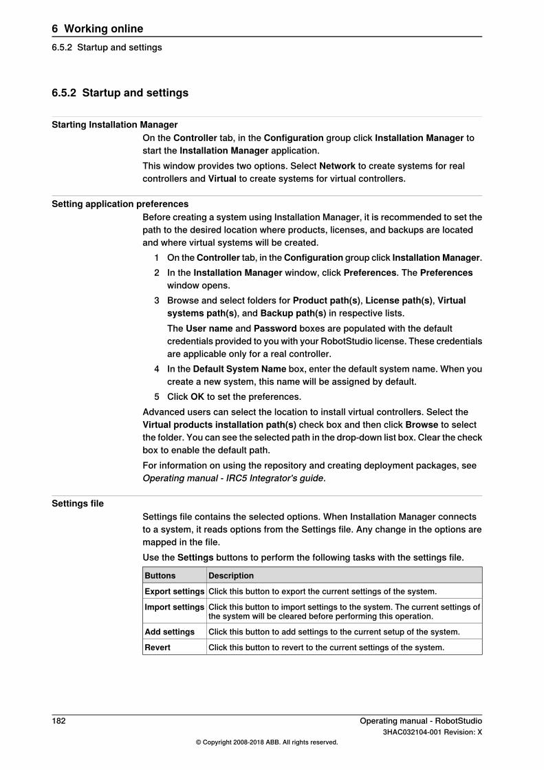
6.5.2 Startup and settings
Starting Installation ManagerOn the Controller tab, in the Configuration group click Installation Manager tostart the Installation Manager application.This window provides two options. Select Network to create systems for realcontrollers and Virtual to create systems for virtual controllers.
Setting application preferencesBefore creating a system using Installation Manager, it is recommended to set thepath to the desired location where products, licenses, and backups are locatedand where virtual systems will be created.
1 On theController tab, in theConfiguration group click InstallationManager.2 In the Installation Manager window, click Preferences. The Preferences
window opens.3 Browse and select folders for Product path(s), License path(s), Virtual
systems path(s), and Backup path(s) in respective lists.The User name and Password boxes are populated with the defaultcredentials provided to you with your RobotStudio license. These credentialsare applicable only for a real controller.
4 In the Default System Name box, enter the default system name. When youcreate a new system, this name will be assigned by default.
5 Click OK to set the preferences.Advanced users can select the location to install virtual controllers. Select theVirtual products installation path(s) check box and then click Browse to selectthe folder. You can see the selected path in the drop-down list box. Clear the checkbox to enable the default path.For information on using the repository and creating deployment packages, seeOperating manual - IRC5 Integrator's guide.
Settings fileSettings file contains the selected options. When Installation Manager connectsto a system, it reads options from the Settings file. Any change in the options aremapped in the file.Use the Settings buttons to perform the following tasks with the settings file.
DescriptionButtons
Click this button to export the current settings of the system.Export settings
Click this button to import settings to the system. The current settings ofthe system will be cleared before performing this operation.
Import settings
Click this button to add settings to the current setup of the system.Add settings
Click this button to revert to the current settings of the system.Revert
182 Operating manual - RobotStudio3HAC032104-001 Revision: X
© Copyright 2008-2018 ABB. All rights reserved.
6 Working online6.5.2 Startup and settings

6.5.3 Building a new system
Creating a new system for a real controller1 In the Installation Manager window, click Controllers, and then click the
Network tab.The Network tab shows the name and IP address of all the availablecontrollers on the LAN network and/or any controller attached through theservice port.
2 Select your controller in the controller list and clickOpen. Installation Managerfetches information from the controller.
3 Click New. The Create New pane appears.4 In theCreate New pane, in theName box, enter the name of the new system.5 Click Next. The Products tab gets selected.6 Click Add, the Select Product window opens. Select the product manifest
file and click OK.If you want to add more products such as Add-ins, clickAdd again and selectthe product. To find a product that is not in the list, click Browse and thenselect the file from the particular folder.
7 Click Next. The Licenses tab gets selected.8 ClickAdd, the Select Licensewindow opens. Select the license file and click
OK.Repeat the step to add multiple license files to your system.
9 Click Next, the Options tab gets selected. This pane shows the SystemOptions, Drive Modules and Applications. Here you are able to customizeyour options.
10 Click Next, the Confirmation tab gets selected and shows an overview ofthe system options.
11 Click Apply, the system gets created on the controller.Once the installation completes, a Restart Controller dialog appears, click Yes torestart the controller. Click No to manually restart controller later, the controllerstores the new system or the changed system and these changes will take effectduring the next restart.
Note
Changing the RobotWare version needs BootServer update. Controller must berestarted for BootServer update. Hence, the controller will be restartedautomatically when you change the RobotWare.
Creating a new system for a virtual controller1 In the Installation Manager window, click Controllers, and then click the
Virtual tab.2 Click New. The Create New pane opens.3 In theCreate New pane, in theName box, enter the name of the new system.
Continues on next pageOperating manual - RobotStudio 1833HAC032104-001 Revision: X
© Copyright 2008-2018 ABB. All rights reserved.
6 Working online6.5.3 Building a new system
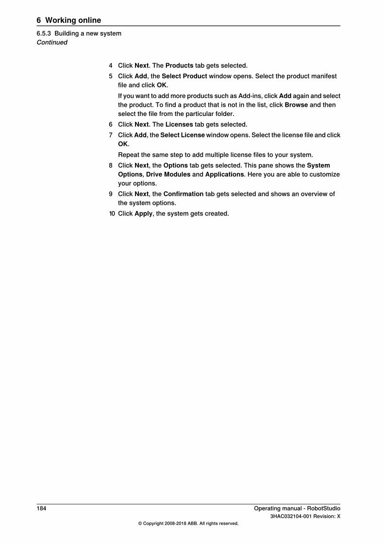
4 Click Next. The Products tab gets selected.5 Click Add, the Select Product window opens. Select the product manifest
file and click OK.If you want to add more products such as Add-ins, clickAdd again and selectthe product. To find a product that is not in the list, click Browse and thenselect the file from the particular folder.
6 Click Next. The Licenses tab gets selected.7 ClickAdd, the Select Licensewindow opens. Select the license file and click
OK.Repeat the same step to add multiple license files to your system.
8 Click Next, the Options tab gets selected. This pane shows the SystemOptions, Drive Modules and Applications. Here you are able to customizeyour options.
9 Click Next, the Confirmation tab gets selected and shows an overview ofthe system options.
10 Click Apply, the system gets created.
184 Operating manual - RobotStudio3HAC032104-001 Revision: X
© Copyright 2008-2018 ABB. All rights reserved.
6 Working online6.5.3 Building a new systemContinued

6.5.4 Modifying a system
Modifying a system for a real controller1 In the Installation Manager window, select Controllers and then select the
Network tab.2 Select your controller in the controller list and clickOpen. Installation Manager
fetches information from the controller.3 Select the particular system that you want to modify.
The Overview pane displays the system options of the selected system.
Note
To be able to modify a system it must first be activated. Select the systemyou want to modify and press the activate button.
4 Click Next. The Products tab gets selected. All products and add-ins thatwere part of the selected system will be displayed here.
• To upgrade/downgrade a product select the product and clickReplace.• To remove a product select the product and click Remove.
Note
It is not possible to remove the RobotWare product.
5 ClickNext. The Licence tab gets selected. The license details of the selectedsystem will be displayed here. Here you are able to add/remove licenses.
6 Click Next. The Options tab gets selected. Here you are able to customizeyour options.
7 Click Next, the Confirmation tab gets selected and shows an overview ofthe system options.
8 Click Apply for the changes to take place.Once the installation completes, a Restart Controller dialog appears, click Yes torestart the controller. Click No to manually restart controller later, the controllerstores the new system or changed system and these changes will take effect duringthe next restart.
Note
Any change in the RobotWare version needs a BootServer update, which requiresa controller restart. The controller will be restarted automatically.
Modifying a system for virtual controller1 In the Installation Manager window, select Controllers and then select the
Virtual. Here you are able to view the list of all virtual systems.2 Select the particular system that you want to modify.
The Overview pane will display the system options of the selected system.
Continues on next pageOperating manual - RobotStudio 1853HAC032104-001 Revision: X
© Copyright 2008-2018 ABB. All rights reserved.
6 Working online6.5.4 Modifying a system
3 Click Next. The Products tab gets selected. All products and add-ins thatwere part of the selected system will be displayed here.
• To upgrade/downgrade a product select the product and clickReplace.• To remove a product select the product and click Remove.
Note
It is not possible to remove the RobotWare product.
4 ClickNext. The Licence tab opens. The license details of the selected systemwill be displayed here. Here you are able to add/remove licenses.
5 Click Next. The Options tab opens. This pane shows the System Options,Drive Modules and Applications. Here you are able to customize youroptions.
6 Click Next, the Confirmation tab gets selected and shows an overview ofthe system options.
7 Click Apply for the changes to take place.
Deleting a system from a real controller1 In the Installation Manager window, select Controllers and then select the
Network tab.2 Select your controller in the controller list and clickOpen. Installation Manager
fetches information from the controller.3 Select the system you want to delete and then click Remove.
The selected system gets deleted.
Note
The active system cannot be deleted. First activate a different system, ordeactivate the system by using the restart mode Start Boot Application.
Deleting a system from virtual controller1 In the Installation Manager window, select Controllers and then select the
Virtual orNetwork tab. Here you are able to view the list of all virtual systems.2 Select the system you want to delete and then click Remove.
The selected system gets deleted.
Note
When you create a system for virtual controller, corresponding products areinstalled in the user APPDATA folder, and many virtual controller systems pointto these products. Hence, products are not deleted while deleting a system fromvirtual controller.
186 Operating manual - RobotStudio3HAC032104-001 Revision: X
© Copyright 2008-2018 ABB. All rights reserved.
6 Working online6.5.4 Modifying a systemContinued

6.5.5 Copying a system
Copying a system from a virtual controller to a real controllerTo be able to copy a system from a virtual controller to a real controller, the virtualcontroller system must have been created with real license files.
1 In the Installation Manager window, select Controllers and then select theNetwork tab.
2 Select your controller in the controller list and click Modify. InstallationManager fetches information from the controller.
3 Click New. The Create New pane opens.4 Enter the name of the system in the Name box, and then click the virtual
system option under Create new from.5 Click Select, the Select Virtual System pane opens, select the particular
system and then click OK.6 Click Next. The Products tab gets selected. All products and add-ins that
were part of the selected system will be displayed here.7 ClickNext. The Licenses tab gets selected. The license details of the selected
system will be displayed here.8 Click Next. The Options tab gets selected. Here you are able to
select/deselect options to customize them.9 Click Next, the Confirmation tab gets selected and shows an overview of
the system options.10 Click Apply, the system gets created.
Once the installation completes, a Restart Controller dialog appears, click Yes torestart the controller. Click No to manually restart controller later, the controllerstores the new system or changed system and these changes will take effect duringthe next restart.
Copying a virtual controller system1 In the Installation Manager window, select Controllers and then select the
Virtual tab. Here you are able to view the list of all virtual systems.2 Click New, the Create New pane opens.3 Enter the name of the virtual system in the Name box, and then click the
virtual system option under Create new from.4 Click Select, the Select Virtual System pane opens, select the particular
system and then click OK.5 Click Next. The Products tab gets selected. All products and add-ins that
were part of the selected system will be displayed here.6 ClickNext. The Licence tab gets selected. The license details of the selected
system will be displayed here.7 Click Next. The Options tab gets selected. Here you are able to
select/deselect options to customize them.8 Click Next, the Confirmation tab gets selected and shows an overview of
the system options.
Continues on next pageOperating manual - RobotStudio 1873HAC032104-001 Revision: X
© Copyright 2008-2018 ABB. All rights reserved.
6 Working online6.5.5 Copying a system
9 Click Apply for the changes to take place.
188 Operating manual - RobotStudio3HAC032104-001 Revision: X
© Copyright 2008-2018 ABB. All rights reserved.
6 Working online6.5.5 Copying a systemContinued

6.5.6 Creating a system from backup
Creating a system from backup for a real controller1 In the Installation Manager window, select Controllers and then select
Network tab.2 Select your controller in the controller list and clickOpen. Installation Manager
fetches information from the controller.3 Click New, the Create New pane opens.4 Enter the name of the system in the Name box, and then click backup option
under Create new from.5 Click Select, the Select Backup pane opens, you can select the particular
backup system and then clickOK. If the right RobotWare already exists, thenthe version will be selected.
Note
In the folder hierarchy of the backup path, the name of the valid backupsystem folder that must be selected will be set in bold. Similarly, namesof all valid backup systems will be marked in bold in the folder hierarchy.User must select one of the valid backup folders for further system creation.
6 Click Next. The Products tab gets selected. All products and add-ins thatwere part of the backup system will be displayed here. You can add new/otherproduct(s) and/or replace RobotWare version if needed.
7 ClickNext. The Licenses tab gets selected. The license details of the backupsystem will be displayed here. You are able to view the license(s) from thebackup system. Here you can add new/more licenses.
8 ClickNext theOptions tab gets selected, select/deselect options to customizethem.
9 Click Next, the Confirmation tab gets selected and shows an overview ofthe system options.
10 Click Apply, the system gets created.Once the installation completes, a Restart Controller dialog appears, clickYes to restart the controller. Click No to manually restart controller later, thecontroller stores the new system or changed system and these changes willtake effect during the next restart.
Creating a system from backup for a virtual controller1 In the Installation Manager window, select Controllers and then select the
Virtual tab. Here you are able to view the list of all virtual systems.2 Click New, the Create New pane opens.3 Enter the name of the system in the Name box, and then click backup option
under Create new from.4 Click Select, the Select Backup pane opens, you can select the particular
backup system and then click OK.
Continues on next pageOperating manual - RobotStudio 1893HAC032104-001 Revision: X
© Copyright 2008-2018 ABB. All rights reserved.
6 Working online6.5.6 Creating a system from backup
If the right RobotWare already exists, then the version will be selected. If theRobotWare does not exist, click Replace to select the RobotWare.
Note
In the folder hierarchy of the backup path, the name of the valid backupsystem folder that must be selected will be set in bold. Similarly, namesof all valid backup systems will be marked in bold in the folder hierarchy.User must select one of the valid backup folders for further system creation.
5 Click Next. The Products tab gets selected.All products and add-ins that were part of the backup system will be displayedhere. You can add new/other product(s) and/or replace RobotWare if needed.
6 Click Next. The Licenses tab gets selected. Here you are able to view thelicense details of the backup system.
7 Click Next, the Options tab gets selected, select/deselect options tocustomize them.
8 Click Next, the Confirmation tab gets selected and shows an overview ofthe system options.
9 Click Apply, the system gets created.
190 Operating manual - RobotStudio3HAC032104-001 Revision: X
© Copyright 2008-2018 ABB. All rights reserved.
6 Working online6.5.6 Creating a system from backupContinued
6.5.7 Renaming a system
Renaming a systemYou can rename an active system for a real controller without re-installation.
1 In the Installation Manager window, select Controllers and then selectNetwork tab.
2 Select the active sytem which must be renamed.3 Click Rename. The Rename System dialog appears.4 In the Enter the new name for the system box, type in the new name.5 Click Rename.
Operating manual - RobotStudio 1913HAC032104-001 Revision: X
© Copyright 2008-2018 ABB. All rights reserved.
6 Working online6.5.7 Renaming a system
6.5.8 A MultiMove system with two coordinated robots
6.5.8.1 Creating a coordinated system using System Builder
OverviewIn this example we will use the System Builder to create a coordinated offlinesystem with one IRB2400 and one IRB1600 robot to use in a new RobotStudiostation.
Starting the New Controller System WizardTo create a system like the one described above, follow these steps:
1 Click System Builder to bring up the dialog box.2 In the dialog box, click Create New to bring up the New Controller System
Wizard.3 Read the welcome text, and click Next to continue to the next page.
Entering the name and path1 In the Name box, enter the name of the system. The name must not contain
blank spaces or non-ASCII characters.In this example, name the system MyMultiMove.
2 In the Path box, enter the path for the folder to save the system in, or clickthe Browse button to browse to the folder or create a new one.In this example, save the system in C:\Program Files\ABB IndustrialIT\Robotics IT\RobotStudio\ABB Library\Training Systems.
3 Click Next to continue to the next page.
Entering the controller key1 Select the Virtual key check box. A virtual controller key now appears in the
Controller Key box. In this example we will use the default media pool andRobotWare version.
2 Click Next to continue to the next page.
Entering drive keys1 Click the Right Arrow button next to the Enter Drive key box twice to create
one drive key for each robot.2 Click Next to continue to the next page.
Adding options1 This system does not require any additional option keys. Click Next and
continue to the next page of the wizard.
Modifying optionsWhen creating robot systems from real robot keys, the key sets the options. Butsince we are using a virtual key, we have to set the options manually.
Continues on next page192 Operating manual - RobotStudio
3HAC032104-001 Revision: X© Copyright 2008-2018 ABB. All rights reserved.
6 Working online6.5.8.1 Creating a coordinated system using System Builder
When creating a system for several manipulators (up to four), you must includeeither of the RobotWare options MultiMove Independent, or MultiMoveCoordinated for the related motion tasks to start.
Note
It is recommended to use the System From Layout function when you createrobot systems for RobotStudio. Then the MultiMove option gets addedautomatically.
To set the options necessary for a MultiMove, follow these steps:1 Scroll down to theRobotWare / Motion Coordination part 1 group and select
the MultiMove Coordinated check box.2 Scroll down to the RobotWare/ Engineering Tools group and select the
Multitasking check box.
Note
The option Advanced RAPID is included in RobotWare- operating systemfrom RobotWare 5.60 and later.
3 Scroll down to the DriveModule1 / Drive module application group andexpand the ABB Standard manipulator option. Select the IRB 2400 Type Aoption, manipulator variant IRB 2400L Type A.
4 Scroll down to the DriveModule2 / Drive module application group andexpand the ABB Standard manipulator option. Select the IRB 1600 option,manipulator variant IRB 1600-5/1.2.
5 Click Finish and the system will be created.
Operating manual - RobotStudio 1933HAC032104-001 Revision: X
© Copyright 2008-2018 ABB. All rights reserved.
6 Working online6.5.8.1 Creating a coordinated system using System Builder
Continued
6.5.8.2 Creating a coordinated system using Installation Manager
OverviewIn this example we will use the Installation Manager to create a coordinated offlinesystem to use in a new RobotStudio station.
Creating a coordinated systemTo create a system like the one described above, follow these steps:
1 In Installation Manager, in the Controllers page select a system and clickNext.
2 In the Product page, click Add, the Select Product dialog box is displayed.3 Select the required product and click OK.4 Select the added product and click Next.5 In the Licenses page, select the required license and click Next.6 In the Options page, under the System Options tab, select the Motion
Coordination > Multimove Options > 604-1 MultiMove Coordinated checkbox. The Engineering Tools option will auto-expand.
7 Under the Engineering Tools option, select the required check boxes andclick Next.
8 In the Confirmation page, review the system configuration and click Apply,to create the system.
194 Operating manual - RobotStudio3HAC032104-001 Revision: X
© Copyright 2008-2018 ABB. All rights reserved.
6 Working online6.5.8.2 Creating a coordinated system using Installation Manager

6.5.9 The recovery disk function
IntroductionThe recovery disk function is for recreating a complete installation of RobotWareand Add-Ins directly to a SD-card in the PC. The recovery disk function can befound under both theController tab and theRepository tab in Installation Manager.
PrerequisitesThe recovery disk function uses information from a backup to recreate theRobotWare system that backup has been generated from.For successful operation these prerequisites are needed:
• A backup for a system using RobotWare 6.0 or later, but not later than theversion of the currently used RobotStudio.
• All products and Add-Ins used by the backup should be located on the pc(RPK:s and RMF:s).
• A SD-card reader.• An original ABB Robotics SD-card.• Administrative rights on the PC.
SD-card creation procedure1 When the disk recovery function is started, the user will be asked to browse
for the backup folder. Once a valid backup directory is selected, the WriteDisk button is active.
2 Before the Write Disk process is started, you will be asked if you want tomake a disk image for product defect report. If yes, define a file name andwhere the information should be stored and then click Save. All data will becopied from the disk to the selected location.
Note
If this function is used, RobotWare defect reports defining reasons for diskrecovery can be sent without having to send in the actual disk.
3 The program will then try to locate all products and add-ins referenced in theselected backup. If one or more product cannot be found, a second directorybrowser will appear and the user will be asked to manually locate the productthat could not be found. The program will remember the parent directory ofthe selected product, and include this directory in later searches.
4 When all products are located, the user will be asked to insert a SD-card intothe computer, or if already present the user will first be asked to remove thecard. This is to ensure that SD-cards are not overwritten by mistake.
5 Once the SD-card is inserted the user is prompted to confirm that the SD-cardwill be permanently overwritten. From this point on and until the operationis complete, the SD-card will be unusable in any other sense than to be usedby the disk recovery function again.
Continues on next pageOperating manual - RobotStudio 1953HAC032104-001 Revision: X
© Copyright 2008-2018 ABB. All rights reserved.
6 Working online6.5.9 The recovery disk function
6 The operation is completed after about one minute, depending on the SD-cardreader performance, and the user is asked to remove the SD-card.
Installation procedure
CAUTION
Always power off the robot controller before changing the SD-card.
1 Power off the robot controller.2 Replace the SD-card in the controller with the recovery SD-card.3 Power on the controller.4 The controller completes the operation by resetting the system to default
values.The text Controller is resetting system might appear on the FlexPendantdepending on how long this operation takes.
5 The RobotWare system starts up.For RobotWare versions greater or equal to 6.04, the backup selected in therecovery disk creator is automatically restored.
The backup can be found with its original name in the following folder:/hd0a/BACKUP.
Erase data from SD-cardThe Clean Disk function will only work on an SD card inserted in the SD card readerof the PC. All data on the SD card will be deleted and a boot application will beinstalled.
CAUTION
The SD-card will be formatted and all information on it will be irreversibly deleted.If any license file shall be saved, please save a backup of the system whichcontains the license file on your PC.
1 Insert the SD-card to be emptied into the SD-card reader of the PC.2 In the Robot Recovery Disk Creator, select Clean Disk and click on Write
Disk.The cleaning may take a few minutes (a progress bar shows the progress). Whenit is finished the SD-card can be removed from the PC and used in a robot controller.A new RobotWare system can now be installed on it.
196 Operating manual - RobotStudio3HAC032104-001 Revision: X
© Copyright 2008-2018 ABB. All rights reserved.
6 Working online6.5.9 The recovery disk functionContinued
6.6 Handle I/O
OverviewThe I/O system handles input and output signals to and from the controller. Beloware the parts of the system described, as well as common types of signals.The I/O system window is used to view and set previously configured signals, andto activate and deactivate devices.
The I/O systemThe I/O system of a controller consists of industrial networks, devices and I/Osignals. The industrial network are the controller's connections for devices (forinstance I/O boards) and the devices contain channels for the actual signals.The industrial networks and devices are displayed in the robot view, as child nodesunder each controller and the I/O signals are displayed in the I/O window.
I/O signalsI/O signals are used to communicate between the controller and external equipment,or to change variables within a robot program.
Input signalsInput signals notify something for the controller, for instance a feeder belt can setan input signal when it has positioned a work piece. The input signal can then beprogrammed to start a specific part of the robot program.
Output signalsThe controller uses output signals to notify that a specified condition has beenfulfilled. For instance, after the robot has finished its sequence, an output signalcan be set. This signal can then be programmed to start a feeder belt, update acounter or trigger any other action.
Simulated signalsA simulated signal is a signal that is manually given a specific value that overridesthe actual signal. Thus simulated signals might be useful for testing robot programswithout activating or running equipment.
Virtual signalsVirtual signals are signals that are not configured to belong to a physical device.Instead, they reside inside the controller's memory. A common use for virtualsignals is to set variables and store changes in a robot program.
ProceduresFor using the I/O system window, see Inputs/Outputs on page 390.For adding a signal, see Add Signals on page 402.
Operating manual - RobotStudio 1973HAC032104-001 Revision: X
© Copyright 2008-2018 ABB. All rights reserved.
6 Working online6.6 Handle I/O
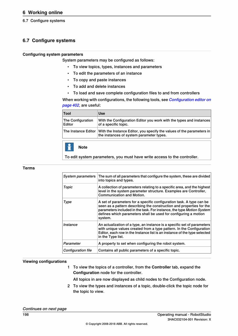
6.7 Configure systems
Configuring system parametersSystem parameters may be configured as follows:
• To view topics, types, instances and parameters• To edit the parameters of an instance• To copy and paste instances• To add and delete instances• To load and save complete configuration files to and from controllers
When working with configurations, the following tools, see Configuration editor onpage 402, are useful:
UseTool
With the Configuration Editor you work with the types and instancesof a specific topic.
The ConfigurationEditor
With the Instance Editor, you specify the values of the parameters inthe instances of system parameter types.
The Instance Editor
Note
To edit system parameters, you must have write access to the controller.
Terms
The sum of all parameters that configure the system, these are dividedinto topics and types.
System parameters
A collection of parameters relating to a specific area, and the highestlevel in the system parameter structure. Examples are Controller,Communication and Motion.
Topic
A set of parameters for a specific configuration task. A type can beseen as a pattern describing the construction and properties for theparameters included in the task. For instance, the typeMotion Systemdefines which parameters shall be used for configuring a motionsystem.
Type
An actualization of a type, an instance is a specific set of parameterswith unique values created from a type pattern. In the ConfigurationEditor, each row in the Instance list is an instance of the type selectedin the Type list.
Instance
A property to set when configuring the robot system.Parameter
Contains all public parameters of a specific topic.Configuration file
Viewing configurations1 To view the topics of a controller, from the Controller tab, expand the
Configuration node for the controller.All topics in are now displayed as child nodes to the Configuration node.
2 To view the types and instances of a topic, double-click the topic node forthe topic to view.
Continues on next page198 Operating manual - RobotStudio
3HAC032104-001 Revision: X© Copyright 2008-2018 ABB. All rights reserved.
6 Working online6.7 Configure systems

The Configuration Editor is now opened, listing all types of the topic in theType name list. In the Instance list, each instance of the type selected in theType name list is displayed as row. The parameter values of the instancesare displayed in the columns of the instance list.
3 To view detailed parameter information for an instance, double-click theinstance.The instance editor now displays the current value, restrictions and limits ofeach parameter in the instance.
Editing parametersYou can either edit the parameters of one single instance, or you can edit severalinstances at one time. Editing several instances at one time is useful when youwant to change the same parameter in several instances, like when moving signalsfrom one device to another.
1 In theController tab, expand theController and theConfiguration node anddouble-click the topic that contains the parameters to edit.This opens the Configuration Editor.
2 In the Type name list of the Configuration Editor, select the type that theparameter to edit belongs to.The instances of the type is now displayed in the Instance list of theConfiguration Editor.
3 In the Instance list, select the instances to edit and press the Enter Key. Toselect several instances at once, hold down the SHIFT or CTRL key whileselecting.Alternatively, right-click an instance and then click Edit.The Instance Editor is now displayed.
4 In the Parameter list of the Instance Editor, select the parameter to edit andchange the value of the parameter in the Value box.When editing several instances at one time, the parameter values you specifywill be applied to all instances. For parameters that you do not specify anynew value, each instance will keep its existing value for that parameter.
5 ClickOK to apply the changes to the configuration database of the controller.For many parameters, the changes will not take affect until the controller isrestarted. If your changes require a restart, you will be notified of this.You have now updated the controller's system parameters. If you are goingto make several changes, you can wait with the restart until all changes aredone.
Continues on next pageOperating manual - RobotStudio 1993HAC032104-001 Revision: X
© Copyright 2008-2018 ABB. All rights reserved.
6 Working online6.7 Configure systems
Continued

Adding instancesWith the Configuration Editor, you can select a type and create a new instance ofit. For example, adding a new instance of the type Signal creates a new signal inthe system.
1 In theController tab, expand theController and theConfiguration node anddouble-click the topic that contains the type of which you want to add aninstance.This opens the Configuration Editor.
2 In the Type name list of the Configuration Editor, select the type of whichyou want to add an instance.
3 On theControllermenu, point toConfiguration and clickAdd type (the wordtype is replaced by the type you selected previously).You can also right-click anywhere in the configuration editor and then selectAdd type from the shortcut menu.A new instance with default values is added and displayed in the InstanceEditor window.
4 If required, edit the values.5 Click OK to save the new instance.
The values in the new instance are now validated. If the values are valid, theinstance is saved. Otherwise, you will be notified of which parameter valuesto correct.For many instances, the changes will not take affect until the controller isrestarted. If your changes require a restart you will be notified of this.You have now updated the controller's system parameters. If the changesrequire a restart of the controller, the changes will not take affect until youdo this. If you are going to make several changes, you can wait with therestart until all changes are done.
Copying an instance1 In theController tab, expand theController and theConfiguration node and
double-click the topic that contains the instance to copy.This opens the Configuration Editor.
2 In the Type name list of the Configuration Editor, select the type of whichyou want to copy an instance.
3 In the Instance list, select one or several instances to copy.If you select several instances and they don't have the same value for allparameters, these parameters will have no default values in the newinstances.
4 On the Controller menu, point to Configuration and click Copy Type (theword type is replaced by the type you selected previously).You can also right-click the instance to copy and then selectCopy Type fromthe shortcut menu.A new instance with the same values as the one you copied is added anddisplayed in the Instance Editor window.
Continues on next page200 Operating manual - RobotStudio
3HAC032104-001 Revision: X© Copyright 2008-2018 ABB. All rights reserved.
6 Working online6.7 Configure systemsContinued

5 Change the name of the instance. If required, also edit the other values.6 Click OK to save the new instance.
The values in the new instance are now validated. If the values are valid, theinstance is saved. Otherwise, you will be notified of which parameter valuesto correct.For many instances, the changes will not take affect until the controller isrestarted. If your changes require a restart you will be notified of this.You have now updated the controller's system parameters. If the changesrequire a restart of the controller, the changes will not take affect until youdo this. If you are going to make several changes, you can wait with therestart until all changes are done.
Deleting an instance1 In theController tab, expand theController and theConfiguration node and
double-click the topic that contains the type of which you want to delete aninstance.This opens the Configuration Editor.
2 In the Type name list of the Configuration Editor, select the type of whichyou want to delete an instance.
3 In the Instance list, select the instance to delete.4 On the Controller menu, point to Configuration and then click Delete type
(the word type is replaced by the type you selected previously).You can also right-click the instance to delete and then select Delete typefrom the shortcut menu.
5 A message box is displayed, asking if you want to delete or keep the instance.Click Yes to confirm that you want to delete it.For many instances, the changes will not take affect until the controller isrestarted. If your changes require a restart you will be notified of this.You have now updated the controller's system parameters. If the changesrequire a restart of the controller, the changes will not take affect until youdo this. If you are going to make several changes, you can wait with therestart until all changes are done.
Save one configuration fileThe system parameters of a configuration topic can be saved to a configurationfile, stored on the PC or any of its network drives.The configuration files can then be loaded into a controller. They are thereby usefulas backups, or for transferring configurations from one controller to another.
1 In the Controller tab, expand the Configuration node and select the topic tosave to a file.
2 On the Controller menu, point to Configuration and select Save SystemParameters.You can also right-click the topic and then select Save System Parametersfrom the shortcut menu.
Continues on next pageOperating manual - RobotStudio 2013HAC032104-001 Revision: X
© Copyright 2008-2018 ABB. All rights reserved.
6 Working online6.7 Configure systems
Continued
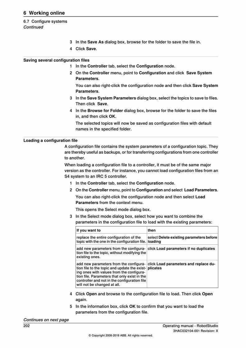
3 In the Save As dialog box, browse for the folder to save the file in.4 Click Save.
Saving several configuration files1 In the Controller tab, select the Configuration node.2 On the Controller menu, point to Configuration and click Save System
Parameters.You can also right-click the configuration node and then click Save SystemParameters.
3 In the Save System Parameters dialog box, select the topics to save to files.Then click Save.
4 In the Browse for Folder dialog box, browse for the folder to save the filesin, and then click OK.The selected topics will now be saved as configuration files with defaultnames in the specified folder.
Loading a configuration fileA configuration file contains the system parameters of a configuration topic. Theyare thereby useful as backups, or for transferring configurations from one controllerto another.When loading a configuration file to a controller, it must be of the same majorversion as the controller. For instance, you cannot load configuration files from anS4 system to an IRC 5 controller.
1 In the Controller tab, select the Configuration node.2 On theControllermenu, point toConfiguration and select Load Parameters.
You can also right-click the configuration node and then select LoadParameters from the context menu.This opens the Select mode dialog box.
3 In the Select mode dialog box, select how you want to combine theparameters in the configuration file to load with the existing parameters:
thenIf you want to
selectDelete existing parameters beforeloading
replace the entire configuration of thetopic with the one in the configuration file.
click Load parameters if no duplicatesadd new parameters from the configura-tion file to the topic, without modifying theexisting ones.
click Load parameters and replace du-plicates
add new parameters from the configura-tion file to the topic and update the exist-ing ones with values from the configura-tion file. Parameters that only exist in thecontroller and not in the configuration filewill not be changed at all.
4 Click Open and browse to the configuration file to load. Then click Openagain.
5 In the information box, click OK to confirm that you want to load theparameters from the configuration file.
Continues on next page202 Operating manual - RobotStudio
3HAC032104-001 Revision: X© Copyright 2008-2018 ABB. All rights reserved.
6 Working online6.7 Configure systemsContinued

6 When the loading of the configuration file is finished, close the Select modedialog box.If a restart of the controller is necessary for the new parameters to take affect,you will be notified of this.
Operating manual - RobotStudio 2033HAC032104-001 Revision: X
© Copyright 2008-2018 ABB. All rights reserved.
6 Working online6.7 Configure systems
Continued
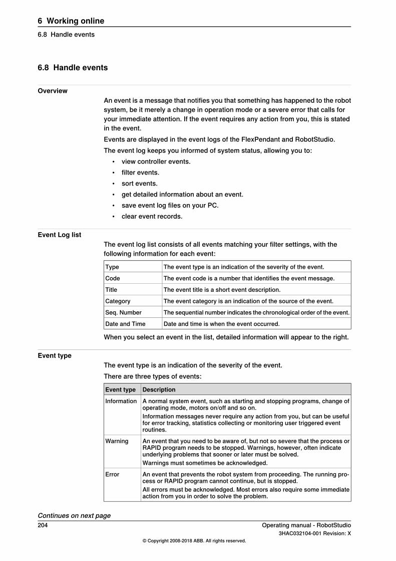
6.8 Handle events
OverviewAn event is a message that notifies you that something has happened to the robotsystem, be it merely a change in operation mode or a severe error that calls foryour immediate attention. If the event requires any action from you, this is statedin the event.Events are displayed in the event logs of the FlexPendant and RobotStudio.The event log keeps you informed of system status, allowing you to:
• view controller events.• filter events.• sort events.• get detailed information about an event.• save event log files on your PC.• clear event records.
Event Log listThe event log list consists of all events matching your filter settings, with thefollowing information for each event:
The event type is an indication of the severity of the event.Type
The event code is a number that identifies the event message.Code
The event title is a short event description.Title
The event category is an indication of the source of the event.Category
The sequential number indicates the chronological order of the event.Seq. Number
Date and time is when the event occurred.Date and Time
When you select an event in the list, detailed information will appear to the right.
Event typeThe event type is an indication of the severity of the event.There are three types of events:
DescriptionEvent type
A normal system event, such as starting and stopping programs, change ofoperating mode, motors on/off and so on.
Information
Information messages never require any action from you, but can be usefulfor error tracking, statistics collecting or monitoring user triggered eventroutines.
An event that you need to be aware of, but not so severe that the process orRAPID program needs to be stopped. Warnings, however, often indicateunderlying problems that sooner or later must be solved.
Warning
Warnings must sometimes be acknowledged.
An event that prevents the robot system from proceeding. The running pro-cess or RAPID program cannot continue, but is stopped.
Error
All errors must be acknowledged. Most errors also require some immediateaction from you in order to solve the problem.
Continues on next page204 Operating manual - RobotStudio
3HAC032104-001 Revision: X© Copyright 2008-2018 ABB. All rights reserved.
6 Working online6.8 Handle events

Note
This information is also indicated by color: blue for information, yellow for warningand red for an error which needs to be corrected in order to proceed
Event codeThe event code is a number that identifies the event message. Together with theevent date and time each event has a unique identity.
Event titleThe event title is a short description of the event.
Event categoryThe category is an indication of the source of the event.
DisplayCategory
All recent events.Common
Events related to changes in operation or operating mode.Operational
Events related to the current system.System
Events related to controller hardware.Hardware
Events related to the running process applications and RAPID pro-grams.
Program
Events related to the movement of robots or other mechanical units.
Motion
Events related to input and output signals, serial or network commu-nication and process buses.
I/O & Communica-tion
Custom messages that have been programed into RAPID programs.User
Internal low-level controller errors for ABB service personnel.Internal
Events related to Industrial Processes options., such as Spot, Arcand Dispense.
Process
Errors in a configuration file.Configuration
Events related to Rapid instruction.RAPID
Depending on how the system is configured, additional categories may exist.
Seq numberThe sequential number indicates the chronological order of the event; the higherthe number the more recently the event occurred.
Date and TimeDate and time indicate exactly when the event occurred. Along with the event code,this timestamp guarantees that each event has a unique identity.
Continues on next pageOperating manual - RobotStudio 2053HAC032104-001 Revision: X
© Copyright 2008-2018 ABB. All rights reserved.
6 Working online6.8 Handle events
Continued
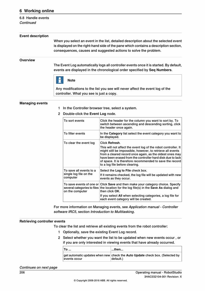
Event descriptionWhen you select an event in the list, detailed description about the selected eventis displayed on the right-hand side of the pane which contains a description section,consequences, causes and suggested actions to solve the problem.
OverviewThe Event Log automatically logs all controller events once it is started. By default,events are displayed in the chronological order specified by Seq Numbers.
Note
Any modifications to the list you see will never affect the event log of thecontroller. What you see is just a copy.
Managing events1 In the Controller browser tree, select a system.2 Double-click the Event Log node.
Click the header for the column you want to sort by. Toswitch between ascending and descending sorting, clickthe header once again.
To sort events
In the Category list select the event category you want tobe displayed.
To filter events
Click Refresh.To clear the event logThis will not affect the event log of the robot controller. Itmight still be impossible, however, to retrieve all eventsfrom a cleared record once again, as the oldest ones mayhave been erased from the controller hard disk due to lackof space. It is therefore recommended to save the recordto a log file before clearing.
Select the Log to File check box.To save all events to asingle log file on thecomputer
If it remains checked, the log file will be updated with newevents as they occur.
Click Save and then make your category choice. Specifythe location for the log file(s) in the Save As dialog andthen click OK.
To save events of one orseveral categories to fileson the computer
If you select All when selecting categories, a log file foreach event category will be created.
For more information on Managing events, see Application manual - Controllersoftware IRC5, section Introduction to Multitasking.
Retrieving controller eventsTo clear the list and retrieve all existing events from the robot controller:
1 Optionally, save the existing Event Log record.2 Select whether you want the list to be updated when new events occur , or
if you are only interested in viewing events that have already occurred.
...then...To ...
check the Auto Update check box. (Selected bydefault.)
get automatic updates when newevents occur
Continues on next page206 Operating manual - RobotStudio
3HAC032104-001 Revision: X© Copyright 2008-2018 ABB. All rights reserved.
6 Working online6.8 Handle eventsContinued

clear the Auto Update check box.say no to automatic updateswhen new events occur
3 To clear the current list, fetch and display all events that are currently storedin the controller log files.
Operating manual - RobotStudio 2073HAC032104-001 Revision: X
© Copyright 2008-2018 ABB. All rights reserved.
6 Working online6.8 Handle events
Continued

This page is intentionally left blank
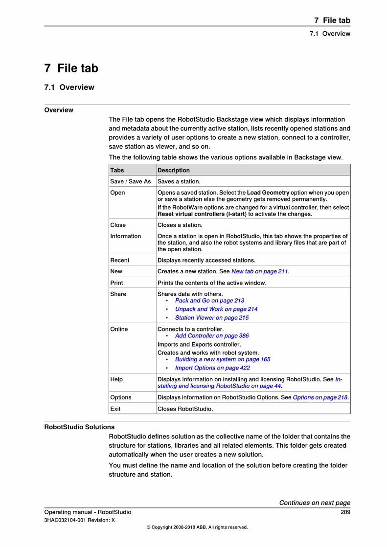
7 File tab7.1 Overview
OverviewThe File tab opens the RobotStudio Backstage view which displays informationand metadata about the currently active station, lists recently opened stations andprovides a variety of user options to create a new station, connect to a controller,save station as viewer, and so on.The the following table shows the various options available in Backstage view.
DescriptionTabs
Saves a station.Save / Save As
Opens a saved station. Select the LoadGeometry option when you openor save a station else the geometry gets removed permanently.
Open
If the RobotWare options are changed for a virtual controller, then selectReset virtual controllers (I-start) to activate the changes.
Closes a station.Close
Once a station is open in RobotStudio, this tab shows the properties ofthe station, and also the robot systems and library files that are part ofthe open station.
Information
Displays recently accessed stations.Recent
Creates a new station. See New tab on page 211.New
Prints the contents of the active window.Print
Shares data with others.• Pack and Go on page 213• Unpack and Work on page 214• Station Viewer on page 215
Share
Connects to a controller.• Add Controller on page 386
Imports and Exports controller.
Online
Creates and works with robot system.• Building a new system on page 165• Import Options on page 422
Displays information on installing and licensing RobotStudio. See In-stalling and licensing RobotStudio on page 44.
Help
Displays information on RobotStudio Options. See Options on page218.Options
Closes RobotStudio.Exit
RobotStudio SolutionsRobotStudio defines solution as the collective name of the folder that contains thestructure for stations, libraries and all related elements. This folder gets createdautomatically when the user creates a new solution.You must define the name and location of the solution before creating the folderstructure and station.
Continues on next pageOperating manual - RobotStudio 2093HAC032104-001 Revision: X
© Copyright 2008-2018 ABB. All rights reserved.
7 File tab7.1 Overview

A solution folder contains the following folders and files:1 Stations: Stations created as part of solution.2 Systems: Virtual controllers created as part of solution3 Libraries: User-defined libraries that are used in the station.4 Solution file: Opening this file opens the solution.
210 Operating manual - RobotStudio3HAC032104-001 Revision: X
© Copyright 2008-2018 ABB. All rights reserved.
7 File tab7.1 OverviewContinued

7.2 New tab
The Backstage viewThe New tab in Backstage view provides many user options. These options aregrouped under the headings Stations and Files.The following table provides the details of the options that are grouped under theseheadings:
LinksTabsHeading
Creating a solution with an empty station onpage 211
Solution with Empty StationStations
Creating a solution with station and robotcontroller on page 211
Solution with Station and RobotController
Creating an empty station on page 212Empty Station
Creating a newRAPIDmodule file on page212RAPID Module FileFiles
Creating a controller configuration file onpage 212
Controller Configuration File
Creating a solution with an empty station1 Click the File tab. The RobotStudio Backstage view appears, click New.2 Under Stations, click Solution with Empty Station.3 Enter the name of the solution in the Solution Name box and then browse
and select the destination folder in the Location box. The default solutionpath is C:\User\<user name>\Documents\RobotStudio\Solutions.The solution name will also be used as the name of the included station.
4 Click Create.The new solution in the specified name gets created. RobotStudio saves thissolution by default.
Creating a solution with station and robot controller1 In the Backstage view, under Stations, click Solution with Station and Robot
Controller.2 Enter the name of the solution in the Solution Name box and then browse
and select the destination folder in the Location box.The default path of solution C:\User\<user
name>\Documents\RobotStudio\Solutions. If you do not specify thename of the solution, RobotStudio assigns the name Solution1 by default.
3 Under the Controller group, enter the name of the controller in the Namebox or select the robot model from the Robot Model list.The default location of the virtual controller system when name of the solutionis not specified is C:\Users\<username>\Documents\RobotStudio\Solutions\Solution1\Systems.
4 Under the Create new group, in the RobotWare list, select the requiredRobotware version or click Locations to set the locations of distribution
Continues on next pageOperating manual - RobotStudio 2113HAC032104-001 Revision: X
© Copyright 2008-2018 ABB. All rights reserved.
7 File tab7.2 New tab

package and media pool. Also, select the required robot model from theRobot Model list to create a controller.
5 To create from backup, selectCreate from backup and then browse to selectthe required backup file. You can also select the RobotWare version followedby the RobotWare Add-in version.Select theRestore backup check box to restore backup on the new controller.
6 Select the option and click Create.
Creating an empty station1 In the Backstage view, under Stations, click Empty Station.2 Click Create.
Creating a new RAPID module file1 In the Backstage view, under Files, click RAPID Module File.2 Choose from the following options:
• Click Module (Program Module) to create a blank RAPID module file.• Click Main Module (Program Module) to create a module with a main
routine.• Click Module (System Module) to create a module with attributes for
read-only, view-only and not step-in.According to the selection you make, the created RAPID module file opensin the RAPID editor.
For more information on managing file based RAPID modules, see Managing filebased RAPID modules on page 461.
Creating a controller configuration file1 In the Backstage view, under Files, click Controller Configuration File.2 You can select any of the following options.
• Empty I/O configuration file to create a blank configuration file• Example I/O configuration file to create an I/O configuration file with
some sample signals.• Empty MMC configuration file to create a blank MMC configuration
file.• EmptyMotion configuration file to create a blank motion configuration
file.• Empty SIO configuration file to create a blank SIO configuration file.• Empty SYS configuration file to create a blank SYS configuration file.
212 Operating manual - RobotStudio3HAC032104-001 Revision: X
© Copyright 2008-2018 ABB. All rights reserved.
7 File tab7.2 New tabContinued
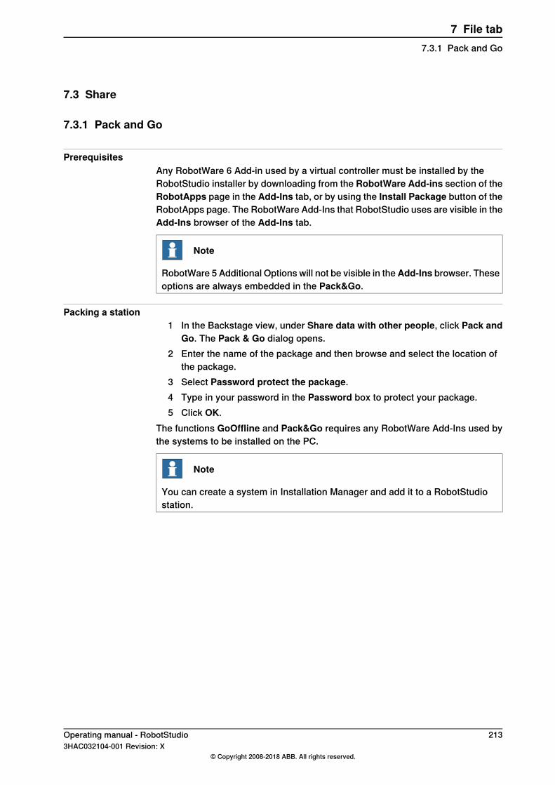
7.3 Share
7.3.1 Pack and Go
PrerequisitesAny RobotWare 6 Add-in used by a virtual controller must be installed by theRobotStudio installer by downloading from the RobotWare Add-ins section of theRobotApps page in the Add-Ins tab, or by using the Install Package button of theRobotApps page. The RobotWare Add-Ins that RobotStudio uses are visible in theAdd-Ins browser of the Add-Ins tab.
Note
RobotWare 5 Additional Options will not be visible in theAdd-Ins browser. Theseoptions are always embedded in the Pack&Go.
Packing a station1 In the Backstage view, under Share data with other people, click Pack and
Go. The Pack & Go dialog opens.2 Enter the name of the package and then browse and select the location of
the package.3 Select Password protect the package.4 Type in your password in the Password box to protect your package.5 Click OK.
The functions GoOffline and Pack&Go requires any RobotWare Add-Ins used bythe systems to be installed on the PC.
Note
You can create a system in Installation Manager and add it to a RobotStudiostation.
Operating manual - RobotStudio 2133HAC032104-001 Revision: X
© Copyright 2008-2018 ABB. All rights reserved.
7 File tab7.3.1 Pack and Go
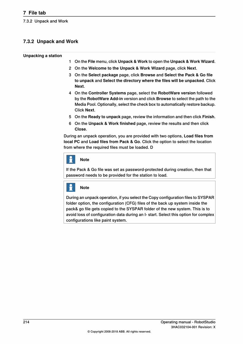
7.3.2 Unpack and Work
Unpacking a station1 On the File menu, click Unpack &Work to open the Unpack &WorkWizard.2 On the Welcome to the Unpack & Work Wizard page, click Next.3 On the Select package page, click Browse and Select the Pack & Go file
to unpack and Select the directory where the files will be unpacked. ClickNext.
4 On the Controller Systems page, select the RobotWare version followedby the RobotWare Add-in version and click Browse to select the path to theMedia Pool. Optionally, select the check box to automatically restore backup.Click Next.
5 On the Ready to unpack page, review the information and then click Finish.6 On the Unpack & Work finished page, review the results and then click
Close.During an unpack operation, you are provided with two options, Load files fromlocal PC and Load files from Pack & Go. Click the option to select the locationfrom where the required files must be loaded. D
Note
If the Pack & Go file was set as password-protected during creation, then thatpassword needs to be provided for the station to load.
Note
During an unpack operation, if you select the Copy configuration files to SYSPARfolder option, the configuration (CFG) files of the back up system inside thepack& go file gets copied to the SYSPAR folder of the new system. This is toavoid loss of configuration data during an I- start. Select this option for complexconfigurations like paint system.
214 Operating manual - RobotStudio3HAC032104-001 Revision: X
© Copyright 2008-2018 ABB. All rights reserved.
7 File tab7.3.2 Unpack and Work
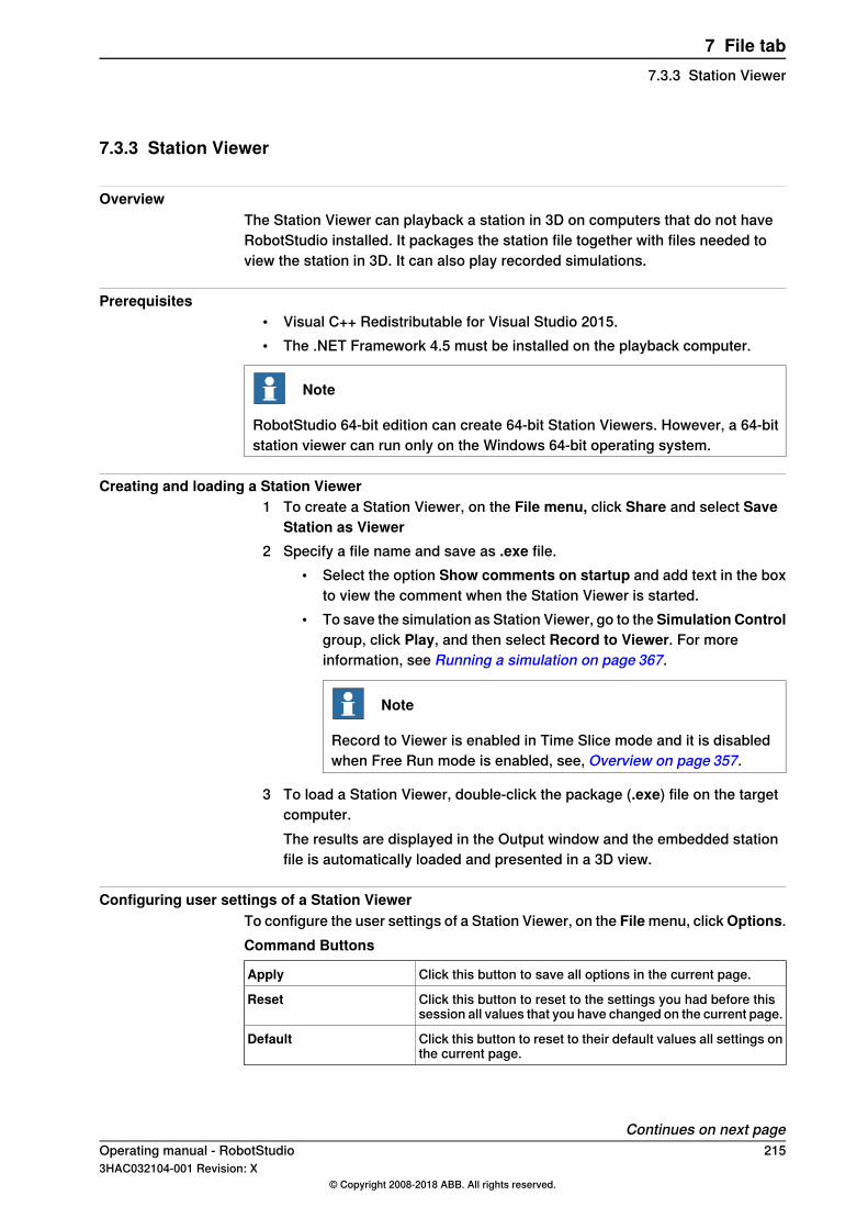
7.3.3 Station Viewer
OverviewThe Station Viewer can playback a station in 3D on computers that do not haveRobotStudio installed. It packages the station file together with files needed toview the station in 3D. It can also play recorded simulations.
Prerequisites• Visual C++ Redistributable for Visual Studio 2015.• The .NET Framework 4.5 must be installed on the playback computer.
Note
RobotStudio 64-bit edition can create 64-bit Station Viewers. However, a 64-bitstation viewer can run only on the Windows 64-bit operating system.
Creating and loading a Station Viewer1 To create a Station Viewer, on the File menu, click Share and select Save
Station as Viewer2 Specify a file name and save as .exe file.
• Select the option Show comments on startup and add text in the boxto view the comment when the Station Viewer is started.
• To save the simulation as Station Viewer, go to the Simulation Controlgroup, click Play, and then select Record to Viewer. For moreinformation, see Running a simulation on page 367.
Note
Record to Viewer is enabled in Time Slice mode and it is disabledwhen Free Run mode is enabled, see, Overview on page 357.
3 To load a Station Viewer, double-click the package (.exe) file on the targetcomputer.The results are displayed in the Output window and the embedded stationfile is automatically loaded and presented in a 3D view.
Configuring user settings of a Station ViewerTo configure the user settings of a Station Viewer, on the Filemenu, clickOptions.Command Buttons
Click this button to save all options in the current page.Apply
Click this button to reset to the settings you had before thissession all values that you have changed on the current page.
Reset
Click this button to reset to their default values all settings onthe current page.
Default
Continues on next pageOperating manual - RobotStudio 2153HAC032104-001 Revision: X
© Copyright 2008-2018 ABB. All rights reserved.
7 File tab7.3.3 Station Viewer
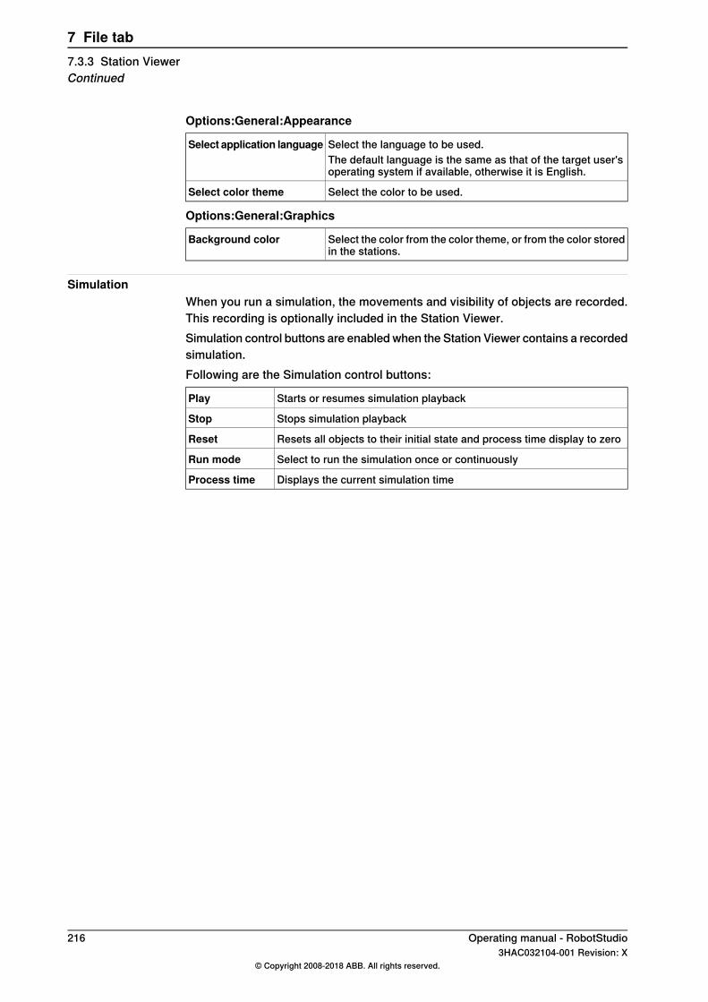
Options:General:Appearance
Select the language to be used.Select application languageThe default language is the same as that of the target user'soperating system if available, otherwise it is English.
Select the color to be used.Select color theme
Options:General:Graphics
Select the color from the color theme, or from the color storedin the stations.
Background color
SimulationWhen you run a simulation, the movements and visibility of objects are recorded.This recording is optionally included in the Station Viewer.Simulation control buttons are enabled when the Station Viewer contains a recordedsimulation.Following are the Simulation control buttons:
Starts or resumes simulation playbackPlay
Stops simulation playbackStop
Resets all objects to their initial state and process time display to zeroReset
Select to run the simulation once or continuouslyRun mode
Displays the current simulation timeProcess time
216 Operating manual - RobotStudio3HAC032104-001 Revision: X
© Copyright 2008-2018 ABB. All rights reserved.
7 File tab7.3.3 Station ViewerContinued
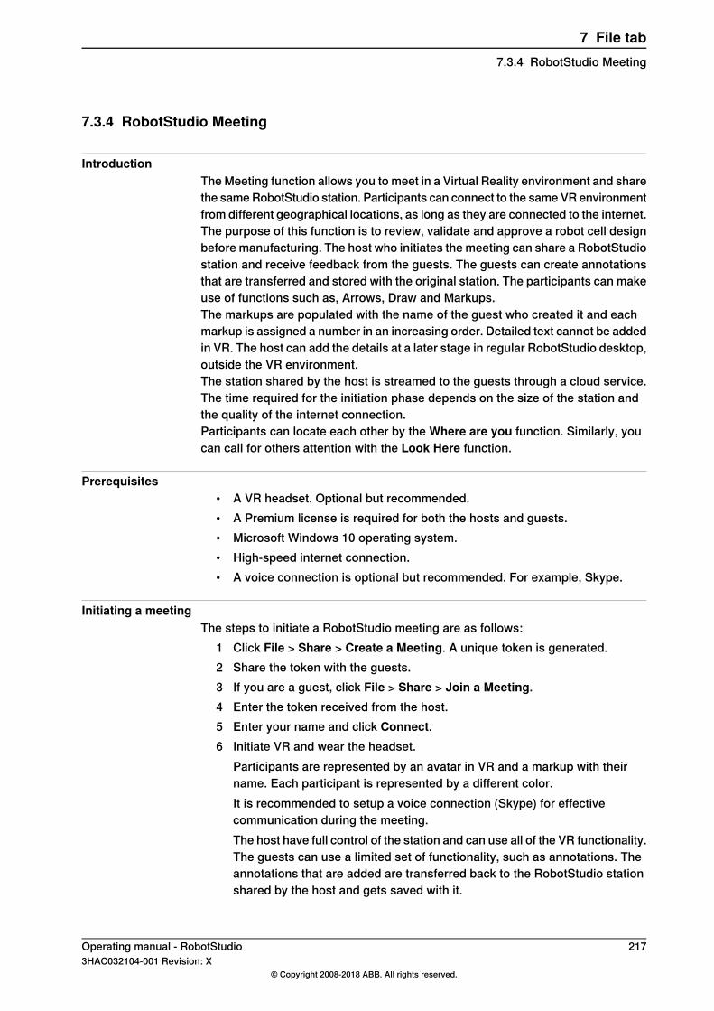
7.3.4 RobotStudio Meeting
IntroductionThe Meeting function allows you to meet in a Virtual Reality environment and sharethe same RobotStudio station. Participants can connect to the same VR environmentfrom different geographical locations, as long as they are connected to the internet.The purpose of this function is to review, validate and approve a robot cell designbefore manufacturing. The host who initiates the meeting can share a RobotStudiostation and receive feedback from the guests. The guests can create annotationsthat are transferred and stored with the original station. The participants can makeuse of functions such as, Arrows, Draw and Markups.The markups are populated with the name of the guest who created it and eachmarkup is assigned a number in an increasing order. Detailed text cannot be addedin VR. The host can add the details at a later stage in regular RobotStudio desktop,outside the VR environment.The station shared by the host is streamed to the guests through a cloud service.The time required for the initiation phase depends on the size of the station andthe quality of the internet connection.Participants can locate each other by the Where are you function. Similarly, youcan call for others attention with the Look Here function.
Prerequisites• A VR headset. Optional but recommended.• A Premium license is required for both the hosts and guests.• Microsoft Windows 10 operating system.• High-speed internet connection.• A voice connection is optional but recommended. For example, Skype.
Initiating a meetingThe steps to initiate a RobotStudio meeting are as follows:
1 Click File > Share > Create a Meeting. A unique token is generated.2 Share the token with the guests.3 If you are a guest, click File > Share > Join a Meeting.4 Enter the token received from the host.5 Enter your name and click Connect.6 Initiate VR and wear the headset.
Participants are represented by an avatar in VR and a markup with theirname. Each participant is represented by a different color.It is recommended to setup a voice connection (Skype) for effectivecommunication during the meeting.The host have full control of the station and can use all of the VR functionality.The guests can use a limited set of functionality, such as annotations. Theannotations that are added are transferred back to the RobotStudio stationshared by the host and gets saved with it.
Operating manual - RobotStudio 2173HAC032104-001 Revision: X
© Copyright 2008-2018 ABB. All rights reserved.
7 File tab7.3.4 RobotStudio Meeting

7.4 Options
Common buttons
Click this button to save all options in the current page.Apply
Click this button to reset to the settings you had before thissession all values that you have changed on the current page.
Reset
Click this button to reset to their default values all settings onthe current page.
Default
Options:General:Appearance
Select the language to be used. RobotStudio is available in thefollowing seven languages: English, French, German, Spanish,Italian, Japanese, and Chinese (simplified).
Select application lan-guage
Select the color to be used.Select color theme
Defines the default scale to use for windows that are zoomable,for example, RAPID Editor, RAPID Data Editor and Configura-tion Editor.
Default scale for zoomablewindows
Select this check box to view ScreenTips.Show ScreenTips
Select the check box if you want to display the position boxesin the modify dialog boxes with colored background. Defaultvalue: selected.
Display Position Editboxes withRed/Green/Blue back-ground
Select this check box to group related document window underone tab. Modifying this option requires a restart for the changesto take effect.
Group related documentwindows under one tab
Select this check box to restore dialogs or messages whichyou may have hidden while using RobotStudio.
Restore hidden dialogsand messages
Options:General:Licensing
Reverts to Basic mode to use features that do not requireactivation.
Disable licensing
Click to view the licenses listed by feature, version, type,expiration date and status.
View installed licenses
Click to activate RobotStudio license.Activation Wizard
For RobotStudio Basic users, it is mandatory to participatein the user experience report.
RobotStudio user experienceprogram
• I want to help improveRobotStudio
• I do not want to particip-ate right now
For RobotStudio Premium users, you can choose whetheror not to participate in the user experience report .
Options:General:Units
Select the quantity for which you want to change the units.Quantity
Select the unit for the quantity.Unit
Enter the number of decimals that you want to be displayed.Display decimals
Enter the number of decimals that you want when modifying.Edit decimals
Continues on next page218 Operating manual - RobotStudio
3HAC032104-001 Revision: X© Copyright 2008-2018 ABB. All rights reserved.
7 File tab7.4 Options

Specifies the default format to use for orientations.Default orientation format• RPY angles (Euler
ZYX)• Quaternions
Options:General:Advanced
The number of operations that can be undone or redone.Lowering this value can decrease memory usage.
Number of undo/redosteps
Warns of orphaned VC processes.Warn about running Virtu-al Controller processes onstartup
Warns when deleting objects.Show acknowledge dialogboxwhen deleting objects
Warns when deleting targets and move instructions.Show acknowledge dialogbox when deleting targetsand corresponding moveinstructions
Select this check box to bring the output window to front if anerror message is displayed
Bring the output windowto front if an error mes-sage is displayed
Options:General:Autosave
This check-box is selected by default. RAPID programs aresaved automatically in every 30 seconds.
Enable autosave of RAPID
Unsaved stations are saved automatically at the intervalspecified in the minute interval box.
Enable autosave of station
Takes multiple backup of station files as specified in theNumber of backups list and saves it in a sub-folder of thecorresponding Stations folder (StationBackups). Requiresa Solution.
Enable automatic backup ofstation files
Select this option to backup the virtual controllers of asolution when saving the station. The backups are storedin the Backups folder of the corresponding solution.
Enable automatic backup ofcontrollers in solution
Options:General:Files & Folders
Shows the default path to the project folder.User Documents location
Shows the default path to the solutions folder.Solutions location
To browse to the project folder, click the browse button....
Select this check box to enable the creation of individual sub-folders for document types.
Automatically create docu-ment subfolders
Specify the interval between the savings when using Autosavein this box.
minute interval
Launches the Document Locations dialog box. For more inform-ation, see Document Locations window on page 70.
Document Locations
Clears the list of recently accessed stations and controllers.Clear Recent Stations andControllers
Continues on next pageOperating manual - RobotStudio 2193HAC032104-001 Revision: X
© Copyright 2008-2018 ABB. All rights reserved.
7 File tab7.4 OptionsContinued
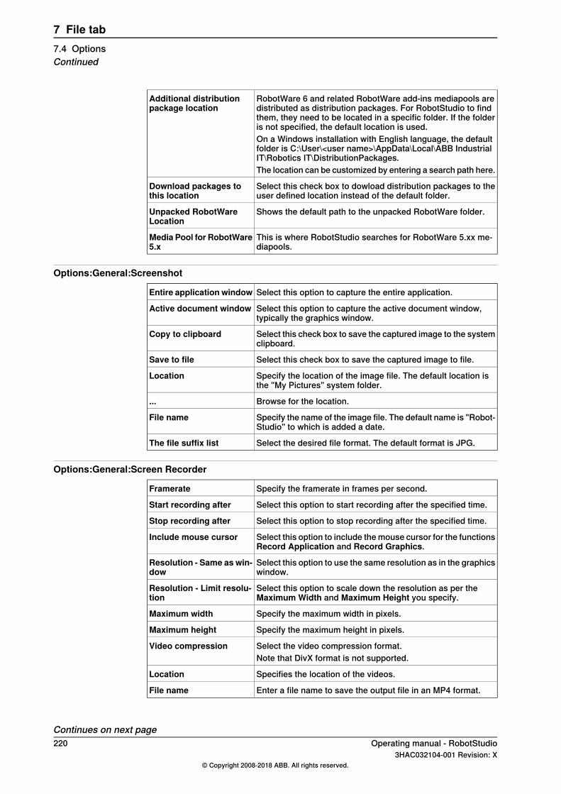
RobotWare 6 and related RobotWare add-ins mediapools aredistributed as distribution packages. For RobotStudio to findthem, they need to be located in a specific folder. If the folderis not specified, the default location is used.
Additional distributionpackage location
On a Windows installation with English language, the defaultfolder is C:\User\<user name>\AppData\Local\ABB IndustrialIT\Robotics IT\DistributionPackages.The location can be customized by entering a search path here.
Select this check box to dowload distribution packages to theuser defined location instead of the default folder.
Download packages tothis location
Shows the default path to the unpacked RobotWare folder.Unpacked RobotWareLocation
This is where RobotStudio searches for RobotWare 5.xx me-diapools.
Media Pool for RobotWare5.x
Options:General:Screenshot
Select this option to capture the entire application.Entire application window
Select this option to capture the active document window,typically the graphics window.
Active document window
Select this check box to save the captured image to the systemclipboard.
Copy to clipboard
Select this check box to save the captured image to file.Save to file
Specify the location of the image file. The default location isthe "My Pictures" system folder.
Location
Browse for the location....
Specify the name of the image file. The default name is "Robot-Studio" to which is added a date.
File name
Select the desired file format. The default format is JPG.The file suffix list
Options:General:Screen Recorder
Specify the framerate in frames per second.Framerate
Select this option to start recording after the specified time.Start recording after
Select this option to stop recording after the specified time.Stop recording after
Select this option to include the mouse cursor for the functionsRecord Application and Record Graphics.
Include mouse cursor
Select this option to use the same resolution as in the graphicswindow.
Resolution - Same as win-dow
Select this option to scale down the resolution as per theMaximum Width and Maximum Height you specify.
Resolution - Limit resolu-tion
Specify the maximum width in pixels.Maximum width
Specify the maximum height in pixels.Maximum height
Select the video compression format.Video compressionNote that DivX format is not supported.
Specifies the location of the videos.Location
Enter a file name to save the output file in an MP4 format.File name
Continues on next page220 Operating manual - RobotStudio
3HAC032104-001 Revision: X© Copyright 2008-2018 ABB. All rights reserved.
7 File tab7.4 OptionsContinued
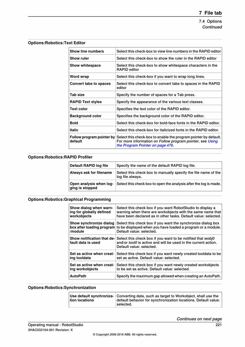
Options:Robotics:Text Editor
Select this check-box to view line numbers in the RAPID editorShow line numbers
Select this check-box to show the ruler in the RAPID editorShow ruler
Select this check-box to show whitespace characters in theRAPID editor
Show whitespace
Select this check-box if you want to wrap long lines.Word wrap
Select this check-box to convert tabs to spaces in the RAPIDeditor
Convert tabs to spaces
Specify the number of spaces for a Tab press.Tab size
Specify the appearance of the various text classes.RAPID Text styles
Specifies the text color of the RAPID editor.Text color
Specifies the background color of the RAPID editor.Background color
Select this check-box for bold-face fonts in the RAPID editor.Bold
Select this check-box for italicized fonts in the RAPID editor.Italic
Select this check-box to enable the program pointer by default.For more information on Follow program pointer, see Usingthe Program Pointer on page 476.
Follow programpointer bydefault
Options:Robotics:RAPID Profiler
Specify the name of the default RAPID log file.Default RAPID log file
Select this check box to manually specify the file name of thelog file always.
Always ask for filename
Select this check box to open the analysis after the log is made.Open analysis when log-ging is stopped
Options:Robotics:Graphical Programming
Select this check box if you want RobotStudio to display awarning when there are workobjects with the same name thathave been declared as in other tasks. Default value: selected.
Show dialog when warn-ing for globally definedworkobjects
Select this check box if you want the synchronize dialog boxto be displayed when you have loaded a program or a module.Default value: selected.
Show synchronize dialogbox after loading program/module
Select this check box if you want to be notified that wobj0and/or tool0 is active and will be used in the current action.Default value: selected.
Show notification that de-fault data is used
Select this check box if you want newly created tooldata to beset as active. Default value: selected.
Set as active when creat-ing tooldata
Select this check box if you want newly created workobjectsto be set as active. Default value: selected.
Set as active when creat-ing workobjects
Specify the maximum gap allowed when creating an AutoPath.AutoPath
Options:Robotics:Synchronization
Converting data, such as target to Workobject, shall use thedefault behavior for synchronization locations. Default value:selected.
Use default synchroniza-tion locations
Continues on next pageOperating manual - RobotStudio 2213HAC032104-001 Revision: X
© Copyright 2008-2018 ABB. All rights reserved.
7 File tab7.4 OptionsContinued
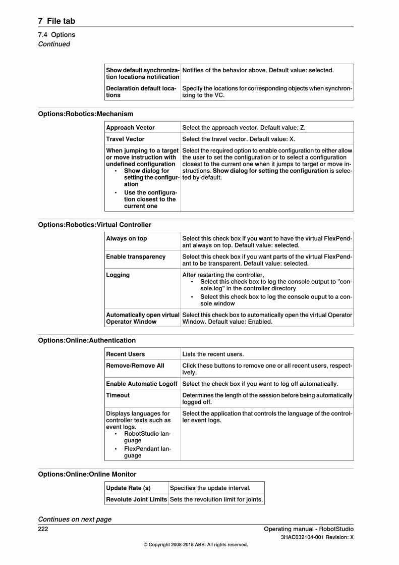
Notifies of the behavior above. Default value: selected.Showdefault synchroniza-tion locations notification
Specify the locations for corresponding objects when synchron-izing to the VC.
Declaration default loca-tions
Options:Robotics:Mechanism
Select the approach vector. Default value: Z.Approach Vector
Select the travel vector. Default value: X.Travel Vector
Select the required option to enable configuration to either allowthe user to set the configuration or to select a configurationclosest to the current one when it jumps to target or move in-structions. Show dialog for setting the configuration is selec-ted by default.
When jumping to a targetor move instruction withundefined configuration
• Show dialog forsetting the configur-ation
• Use the configura-tion closest to thecurrent one
Options:Robotics:Virtual Controller
Select this check box if you want to have the virtual FlexPend-ant always on top. Default value: selected.
Always on top
Select this check box if you want parts of the virtual FlexPend-ant to be transparent. Default value: selected.
Enable transparency
After restarting the controller,• Select this check box to log the console output to "con-
sole.log" in the controller directory• Select this check box to log the console ouput to a con-
sole window
Logging
Select this check box to automatically open the virtual OperatorWindow. Default value: Enabled.
Automatically open virtualOperator Window
Options:Online:Authentication
Lists the recent users.Recent Users
Click these buttons to remove one or all recent users, respect-ively.
Remove/Remove All
Select the check box if you want to log off automatically.Enable Automatic Logoff
Determines the length of the session before being automaticallylogged off.
Timeout
Select the application that controls the language of the control-ler event logs.
Displays languages forcontroller texts such asevent logs.
• RobotStudio lan-guage
• FlexPendant lan-guage
Options:Online:Online Monitor
Specifies the update interval.Update Rate (s)
Sets the revolution limit for joints.Revolute Joint Limits
Continues on next page222 Operating manual - RobotStudio
3HAC032104-001 Revision: X© Copyright 2008-2018 ABB. All rights reserved.
7 File tab7.4 OptionsContinued
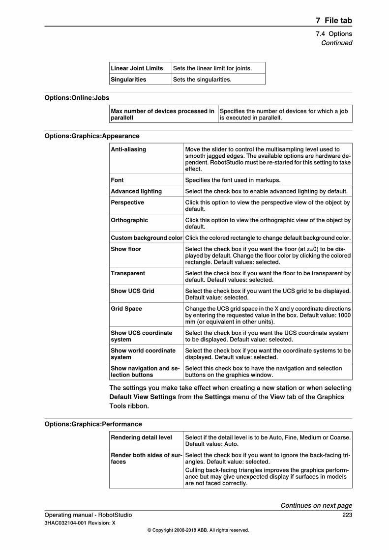
Sets the linear limit for joints.Linear Joint Limits
Sets the singularities.Singularities
Options:Online:Jobs
Specifies the number of devices for which a jobis executed in parallell.
Max number of devices processed inparallell
Options:Graphics:Appearance
Move the slider to control the multisampling level used tosmooth jagged edges. The available options are hardware de-pendent. RobotStudio must be re-started for this setting to takeeffect.
Anti-aliasing
Specifies the font used in markups.Font
Select the check box to enable advanced lighting by default.Advanced lighting
Click this option to view the perspective view of the object bydefault.
Perspective
Click this option to view the orthographic view of the object bydefault.
Orthographic
Click the colored rectangle to change default background color.Custombackground color
Select the check box if you want the floor (at z=0) to be dis-played by default. Change the floor color by clicking the coloredrectangle. Default values: selected.
Show floor
Select the check box if you want the floor to be transparent bydefault. Default values: selected.
Transparent
Select the check box if you want the UCS grid to be displayed.Default value: selected.
Show UCS Grid
Change the UCS grid space in the X and y coordinate directionsby entering the requested value in the box. Default value: 1000mm (or equivalent in other units).
Grid Space
Select the check box if you want the UCS coordinate systemto be displayed. Default value: selected.
Show UCS coordinatesystem
Select the check box if you want the coordinate systems to bedisplayed. Default value: selected.
Show world coordinatesystem
Select this check box to have the navigation and selectionbuttons on the graphics window.
Show navigation and se-lection buttons
The settings you make take effect when creating a new station or when selectingDefault View Settings from the Settings menu of the View tab of the GraphicsTools ribbon.
Options:Graphics:Performance
Select if the detail level is to be Auto, Fine, Medium or Coarse.Default value: Auto.
Rendering detail level
Select the check box if you want to ignore the back-facing tri-angles. Default value: selected.
Render both sides of sur-faces
Culling back-facing triangles improves the graphics perform-ance but may give unexpected display if surfaces in modelsare not faced correctly.
Continues on next pageOperating manual - RobotStudio 2233HAC032104-001 Revision: X
© Copyright 2008-2018 ABB. All rights reserved.
7 File tab7.4 OptionsContinued

Select the size in pixels under which objects will be disreg-arded. Default value: 2 pixels.
Cull objects smaller than
The settings you make here are generic for all objects in RobotStudio. With theGraphic Appareance dialog box you can, however, override some of these settingsfor single objects.
Options:Graphics:Behavior
Select a navigational activity and then specify the mouse but-tons to be used for the selected navigational activity.
Navigation
Select the navigation sensitivity when using the mouse move-ments or navigation buttons by clicking the bar and draggingit into position. Default value: 1.
Navigation sensitivity
Select to automatically adjust the view center distance whenrotating or zooming a 3D view.
Automatically adjust viewcenter distance
Change the selection radius (that is, how close the mousecursor click must be to an item to be selected) by entering therequested pixel value in the box. Default value: 5.
Selection radius (pixels)
Click the colored rectangle to change the highlight color.Selection highlight color
Select the check box to enable temporarily highlighting of itemsthat may be selected when the mouse cursor passes over them.Default value: selected.
Selection preview
Select the check box to show the local coordinate system forthe selected objects. Default value: selected.
Show local coordinatesystem for selected ob-jects
Options:Graphics:Geometry
Specify the level of detail required when importing geometries.Detail LevelSelect Fine, Medium or Coarse as required.
Options:Graphics:Stereo/VR*
Displays the image available in the VR glasses in the Graphics view.Mirror Output
Move the slider to adjust the quality of the image to an acceptablelevel of lag.
Quality
This option is disabled by default for better performance.Disable Anti-Aliasing
Options:Simulation:Clock
Sets the simulation speed relative to real time. You can definethe simulation speed to a maximum of 200%
Simulation speed
Select this check box to run the simulation as fast as possible.As fast as possibleWhen you select this option, the simulation speed slider isdisabled.
Specifies the simulation timestep.Simulation timestep
When simulating a large number of controllers (such as tencontrollers), this option may increase performance by utilizingmultiple CPU cores.This option is hardware dependent and hence may give differ-ent results depending on the computer used.
Run time slice in parallelfor multiple controllers
Continues on next page224 Operating manual - RobotStudio
3HAC032104-001 Revision: X© Copyright 2008-2018 ABB. All rights reserved.
7 File tab7.4 OptionsContinued
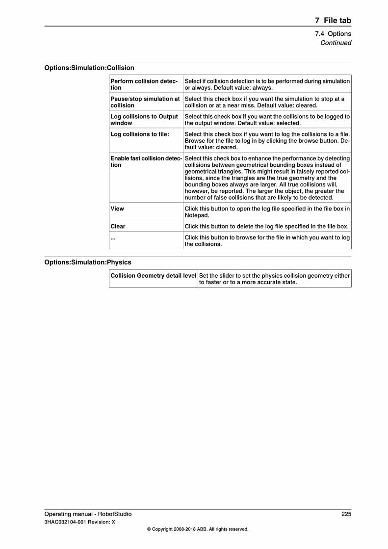
Options:Simulation:Collision
Select if collision detection is to be performed during simulationor always. Default value: always.
Perform collision detec-tion
Select this check box if you want the simulation to stop at acollision or at a near miss. Default value: cleared.
Pause/stop simulation atcollision
Select this check box if you want the collisions to be logged tothe output window. Default value: selected.
Log collisions to Outputwindow
Select this check box if you want to log the collisions to a file.Browse for the file to log in by clicking the browse button. De-fault value: cleared.
Log collisions to file:
Select this check box to enhance the performance by detectingcollisions between geometrical bounding boxes instead ofgeometrical triangles. This might result in falsely reported col-lisions, since the triangles are the true geometry and thebounding boxes always are larger. All true collisions will,however, be reported. The larger the object, the greater thenumber of false collisions that are likely to be detected.
Enable fast collisiondetec-tion
Click this button to open the log file specified in the file box inNotepad.
View
Click this button to delete the log file specified in the file box.Clear
Click this button to browse for the file in which you want to logthe collisions.
...
Options:Simulation:Physics
Set the slider to set the physics collision geometry eitherto faster or to a more accurate state.
Collision Geometry detail level
Operating manual - RobotStudio 2253HAC032104-001 Revision: X
© Copyright 2008-2018 ABB. All rights reserved.
7 File tab7.4 OptionsContinued

This page is intentionally left blank
8 Home tab8.1 Overview
The Home tabThe Home tab contains the controls required for building stations, creating systems,programming paths and placing items.
Operating manual - RobotStudio 2273HAC032104-001 Revision: X
© Copyright 2008-2018 ABB. All rights reserved.
8 Home tab8.1 Overview
8.2 ABB Library
About this buttonWith this button, you can choose robots, positioners and tracks from their respectivegalleries.
228 Operating manual - RobotStudio3HAC032104-001 Revision: X
© Copyright 2008-2018 ABB. All rights reserved.
8 Home tab8.2 ABB Library

8.3 Import Library
About this buttonWith this button, you can import equipment, geometries, positioners, robots, toolsand training objects to your station libraries.
Importing a libraryUse this procedure for importing library files to a station:
1 On the Home menu, click Import Library and select one of the followingcontrols:
• Equipment• User Library• Documents• Locations• Browse for Library
Note
You can also import component xml files (*.rsxml) to your station.
2 Click Equipment to import predefined ABB mechanism libraries.3 Click User Library to select the user defined libraries.4 Click Documents to open the Documents window. See The Documents
window on page 655 Click Locations to open the Document Locations window. See Document
Locations window on page 70.6 Click Browse for Library to select the saved library files.
Operating manual - RobotStudio 2293HAC032104-001 Revision: X
© Copyright 2008-2018 ABB. All rights reserved.
8 Home tab8.3 Import Library

8.4 Robot System
8.4.1 Robot System
About this buttonWith the Robot System button, you can either create a system from layout ortemplate, choose an existing system, or select a system from a robot gallery andsetup a conveyor tracking mechanism.
Creating a system from layout1 Click From Layout to bring up the first page of the wizard.2 In the Name box, enter the name of the system. The location of the system
will be displayed in the Location box.3 In the RobotWare list, select the version of RobotWare you want to use.4 Click Next.5 In the Mechanisms box, select the mechanisms that you want to include in
the system.6 Click Next.
The wizard now proposes a mapping of the mechanisms to a specific motiontask, in accordance with the following rules:
• Only one TCP robot is allowed per task.• Up to seven motion tasks may be added, but only four TCP robots can
be used, and they must be assigned to the first four tasks.• The number of tasks may not exceed the number of mechanisms.• If the system contains one TCP robot and one external axis, they will
be assigned to the same task. It is, however, possible to add a newtask and assign the external axis to it.
• If the system contains more than one TCP robot, any external axes willbe assigned to a separate task. It is, however, possible to move themto other tasks.
• The number of external axes in a task is limited by the number ofavailable drive modules in the cabinet (one for large robots, two formedium, three for small).
If only one mechanism was selected in the previous page, this page will notbe shown.Tasks can be added and removed using the respective buttons; mechanismscan be moved up or down using the respective arrows. To map themechanisms to tasks, follow this step:
7 Optionally, make any edits in the mapping, and then click Next.The System Option page appears.
Continues on next page230 Operating manual - RobotStudio
3HAC032104-001 Revision: X© Copyright 2008-2018 ABB. All rights reserved.
8 Home tab8.4.1 Robot System
8 On the System Option page, you have the option to align Task Frame(s) withthe corresponding Base Frame(s).
• For single robot system, select the checkbox to align task frame withbase frame:
• For MultiMove Independent system, select the check box to align taskframe with base frame for each robot.
• For MultiMove Coordinated system, select the robot from the dropdown list and select the check box to align task frame with base framefor the selected robot.
9 Verify the summary and then click Finish.If the system contains more than one robot, the number of tasks and thebaseframe positions of the mechanism should be verified in the SystemConfiguration window.
Note
To create a system from layout, all your mechanisms such as robots, trackmotions and positioners, must be saved as libraries.
Creating a New System1 Click New System to bring up a dialog box.2 Under the Controller group, enter the name of the controller in the Name
box.The default location of the virtual controller system when name of the solutionis not specified is C:\Users\<username>\Documents\RobotStudio\Solutions\Solution1\Systems.
3 Under the Create new group, select the required Robotware version or clickLocations to set the locations of distribution package and media pool. Also,select the required robot model from the Robot Model list to create acontroller.
4 To create from backup, selectCreate from backup and then browse to selectthe required backup file. You can also select the RobotWare version followedby the RobotWare Add-in version. Select the Restore backup check box torestore backup on the new controller.
5 In the Libraries group, select whether to import libraries or to use the existingstation libraries.
Adding an existing system1 Click Existing to bring up a dialog box.2 In the Select System Pool list, select a folder.3 In the Systems Found list, select a system.4 In the Libraries group, select whether to import libraries or to use the existing
station libraries.5 Click OK.
Continues on next pageOperating manual - RobotStudio 2313HAC032104-001 Revision: X
© Copyright 2008-2018 ABB. All rights reserved.
8 Home tab8.4.1 Robot System
Continued

Selecting a system from a robot gallery1 Click Quick System to bring up a gallery, and then click the appropriate
robot.
Adding objects to the conveyor1 In the Layout browser, click the conveyor node.2 Right-click Workpiece source folder and click Add objects to workpiece
source.3 In the Set Pitch tab, select the part from Available Parts.4 Enter required Pitch value and set Offset position and Offset orientation.5 Click Create.
Modifying the connection between VC and conveyor1 In the Layout browser, click the Conveyor node.2 Click Connections.3 Right-click Connections and select Modify Connection.4 In the Modify Connection tab, enter new values.5 Click Apply.
Removing objects from conveyor1 In the Layout browser, click the Conveyor node.2 Click the Workpiece source node.3 Right-click the part that must be removed, and click Remove.
Clear conveyorUse this option to detatch workobjects, to clear the placed objects and to reset theconveyor to its start position. To access this option, In the Layout browser right-clickthe conveyor and click Clear.
232 Operating manual - RobotStudio3HAC032104-001 Revision: X
© Copyright 2008-2018 ABB. All rights reserved.
8 Home tab8.4.1 Robot SystemContinued
8.4.2 External Axis Wizard
OverviewThe ABB IRC5 controller is capable of controlling a vast number of mechanicalunits other than the ABB robot manipulator. Some external equipment such asworkpiece positioners and robot tracks are standard ABB equipment for whichABB supplies and maintains controller system configuration files. But in manysituations there is a need for customized external equipment.It is possible to use standard ABB motor units and gear units in customized externalequipment. The configuration file of the motor unit or gear unit in isolation issupplied and maintained by ABB. The External Axis Wizard tool simplifies thecontroller configuration for different combinations of motor units and gear units incustomized mechanical units.Mechanism modeling functionality in RobotStudio makes it is possible to definecustom kinematic mechanisms. The External Axis Wizard lets you specifymechanisms to include in the system. First, connect and configure each axis in amechanism to a corresponding motor unit or gear unit. Then, the templateconfiguration files are used to assemble a complete system configuration accordingto specification.
Note
The External Axis Wizard can be downloaded from the RobotApps website. Toaccess the RobotApps website, visit www.abb.com/roboticssoftware.
LimitationFor IRC5P systems (used for painting), the External Axis Wizard supports only upto three external axes.
Prerequisites• Build the station, and import or model the geometry of the mechanism. For
information about creating a new station, see Workflow of building a stationon page 81.
• Use the Mechanism Modeling functionality to define custom kinematicmechanisms. For more information, see Create Mechanism on page 344.
• Add a virtual controller to the station, and include additional drivescorresponding to the axes of the mechanism to the controller system.
• The robot will not be attached to the mechanism. You must manually attachthe robot to the external axis after successful configuration by the ExternalAxis Wizard.
Using the External Axis Wizard1 From the Robot System menu, click External Axis Wizard.
The first page of the wizard appears. It lists the the previously definedmechanisms (including robots) in the Mechanisms box.
Continues on next pageOperating manual - RobotStudio 2333HAC032104-001 Revision: X
© Copyright 2008-2018 ABB. All rights reserved.
8 Home tab8.4.2 External Axis Wizard
2 From the Mechanisms box, select the mechanisms to include in the system.• The mechanism model must be built in such a way that a kinematics
model can be created. The joint chain must be defined such that it canbe described by Denavit-Hartenberg parameters. The mechanismmodel must sometimes be modified to be able to keep the flange inthe desired position. This can be done automatically by the ExternalAxis Wizard, by adding a locked axis.
• For adding an additional locked axis, when prompted, click Ok.This is a dummy axis with frame definition. This dummy axis is addedto the controller configuration and also to the RobotStudio mechanism.You cannot jog this additional axis.
3 Click Next.The mechanisms along with their joints are listed.
4 Configure theMechanical Unit based on the following information. The nameof the mechanism in RobotStudio corresponds to the mechanical unit of themotion configuration.
• Select the drive module (DM1 - DM4) to use for the mechanical unit.If the mechanism has more than three joints, or, if there are severalexternal mechanisms which are to be part of the configuration, thenyou need to use additional drive modules. In such cases, before usingthe External Axis Wizard, configure the controller system with theappropriate number of drive modules.
• Optionally, you can use an Activation Relay by selecting thecorresponding check box.For more information, see Technical reference manual - Systemparameters (3HAC050948-001).
• For two axis positioners with rotating axes, where the two axes are inseries, you can optionally select the Error Model check box.Mechanisms defined with the error model can be calibrated with theFlexPendant using the standard four point method for each axis. Thiswill compensate for deviations present in the real mechanisms.
• You can configure two mechanical units to share a drive module.To share the drive module with a mechanical unit, select thatmechanical unit in the Common Drive list. The list shows allmechanisms (except TCP robot) with the same number of joints as theselected one. The joints of the mechanical units use the same logicalaxis and drive module. Note that the common drive option is notavailable unless an activation relay is chosen for the mechanical unit.This ensures that two mechanical units sharing a drive cannot beactivated at the same time.
5 Configure the joint based on the following information.• For each joint select the Motor Unit. You can select a motor unit (MU),
or a gear unit (MTD), or an interchange unit (MID). The list is populatedwith the standard motor and gear units provided by ABB.
Continues on next page234 Operating manual - RobotStudio
3HAC032104-001 Revision: X© Copyright 2008-2018 ABB. All rights reserved.
8 Home tab8.4.2 External Axis WizardContinued

Your choice will affect the capacity and cycle time of the external axis.• Electronically linked motors are two motor units that drive the same
axis. To link a motor unit to another one electronically, select therespective joint in the Follow list.
• The Drive Unit list is populated with the available drive units of thesystem. Each joint will be represented by its selected drive unit.
• You can configure Logical Axis, Transmission, Link,Board andNodeaccording to your needs.For more information, see Technical reference manual - Systemparameters (3HAC050948-001).
Note
Default values are given for all attributes, except Motor Unit. However, youmust review and change to the correct parameters to give a validconfiguration.
6 Click Next.The Finish page comes up.
7 To save the configuration to a file, click Save.The configured kinematics of external axis devices are saved to aconfiguration file.
8 To load the saved configuration to the system on exiting from the wizard,select the Load Configuration to System check box.
9 Click Finish to exit the wizard.Use the saved configuration files to assemble a complete controller systemconfiguration according to specification. When a system is configured, the MOC.cfgfile with a subset for the external equipment is saved and a virtual controller isstarted for verification.
Note
All mechanisms which have been used in this configuration will be disconnectedfrom the library. To maintain these changes in a library file (.rslib), you need tomanually save it. This is because the External Axis Wizard may have automaticallyadjusted the mechanisms to enable them to be configured.
Operating manual - RobotStudio 2353HAC032104-001 Revision: X
© Copyright 2008-2018 ABB. All rights reserved.
8 Home tab8.4.2 External Axis Wizard
Continued

8.5 Import Geometry
Importing geometry1 On the Home menu, click Import Geometry and select one of the following
controls:• User Geometry• Browse for Geometry
2 Click User Geometry to select the user defined geomtery.3 Click Browse for Geometry to browse to the folder where the geometry is
located.For predefined geometries, click the Geometry icon to the left in the dialogbox.
4 Select the required geometry and click Open.If you want the geometry to move with another object, attach it to therequested object, see Attach to on page 496.To modify the detail level for import of geometries, see Options on page218.
Note
The Modeling tab also contains the Import Geometry option.
236 Operating manual - RobotStudio3HAC032104-001 Revision: X
© Copyright 2008-2018 ABB. All rights reserved.
8 Home tab8.5 Import Geometry

8.6 Export Geometry
OverviewThe Export Geometry command is available for component groups, parts, stationsand mechanism links. Right-click an open group, station, part or mechanism linkand then select Export Geometry to access this command.
Exporting Geometry in a station1 In the Layout browser, right-click an open station and select Export
Geometry.2 The ExportGeometry:Station pane opens, select the required format from
the Format list.3 Click Export and select the destination folder.
You can use these steps for a component group, part or mechanism link.
Supported formatsIt is possible to export geometry in the following formats in a station.
DescriptionFormat
Selecting this format provides two export options, Export invisible objectsand Only export objects intersecting the floor. You can configure the viewand export all objects or only objects that touch the floor.
dxf, svg(2D formats)
When you select Only export objects intersecting the floor option, enterthe value of Floor height (mm).It is possible to export a RobotStudio function as a 2D floor layout when theView point is set to Top.
When you select this format, Export invisible objects check box is displayed,select this option to export all invisible objects in the station.
dae(3D format)
The supported export formats vary for component groups, parts and mechanismlinks. The following table lists various supported formats for exporting geometryfor each of these elements:
Supported formatsElements
COLLADA(dae)Group
ACIS(sat), IGES(igs, iges), STEP(stp, step, p21), VDAFS(vda,vdafs), Catia v4(model, exp), COLLADA(dae), OBJ(obj),RSGFX(rsgfx), VRML2, STL.
Mechanism links, Parts
Operating manual - RobotStudio 2373HAC032104-001 Revision: X
© Copyright 2008-2018 ABB. All rights reserved.
8 Home tab8.6 Export Geometry
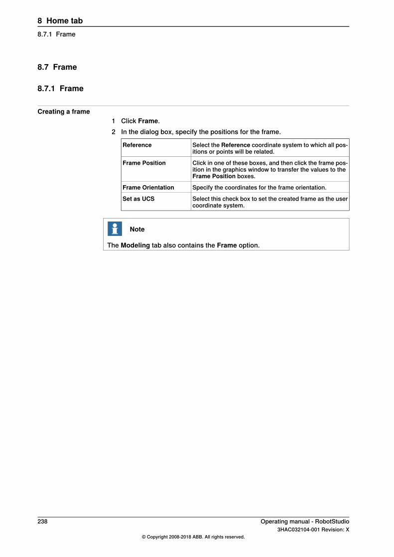
8.7 Frame
8.7.1 Frame
Creating a frame1 Click Frame.2 In the dialog box, specify the positions for the frame.
Select the Reference coordinate system to which all pos-itions or points will be related.
Reference
Click in one of these boxes, and then click the frame pos-ition in the graphics window to transfer the values to theFrame Position boxes.
Frame Position
Specify the coordinates for the frame orientation.Frame Orientation
Select this check box to set the created frame as the usercoordinate system.
Set as UCS
Note
The Modeling tab also contains the Frame option.
238 Operating manual - RobotStudio3HAC032104-001 Revision: X
© Copyright 2008-2018 ABB. All rights reserved.
8 Home tab8.7.1 Frame
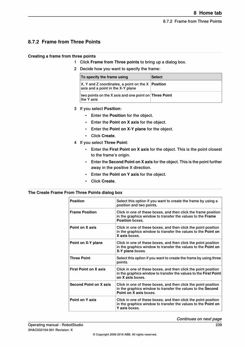
8.7.2 Frame from Three Points
Creating a frame from three points1 Click Frame from Three points to bring up a dialog box.2 Decide how you want to specify the frame:
SelectTo specify the frame using
PositionX, Y and Z coordinates, a point on the Xaxis and a point in the X-Y plane
Three Pointtwo points on the X axis and one point onthe Y axis
3 If you select Position:• Enter the Position for the object.• Enter the Point on X axis for the object.• Enter the Point on X-Y plane for the object.• Click Create.
4 If you select Three Point:• Enter the First Point on X axis for the object. This is the point closest
to the frame’s origin.• Enter the Second Point on X axis for the object. This is the point further
away in the positive X direction.• Enter the Point on Y axis for the object.• Click Create.
The Create Frame From Three Points dialog box
Select this option if you want to create the frame by using aposition and two points.
Position
Click in one of these boxes, and then click the frame positionin the graphics window to transfer the values to the FramePosition boxes.
Frame Position
Click in one of these boxes, and then click the point positionin the graphics window to transfer the values to the Point onX axis boxes.
Point on X axis
Click in one of these boxes, and then click the point positionin the graphics window to transfer the values to the Point onX-Y plane boxes.
Point on X-Y plane
Select this option if you want to create the frame by using threepoints.
Three Point
Click in one of these boxes, and then click the point positionin the graphics window to transfer the values to the First Pointon X axis boxes.
First Point on X axis
Click in one of these boxes, and then click the point positionin the graphics window to transfer the values to the SecondPoint on X axis boxes.
Second Point on X axis
Click in one of these boxes, and then click the point positionin the graphics window to transfer the values to the Point onY axis boxes.
Point on Y axis
Continues on next pageOperating manual - RobotStudio 2393HAC032104-001 Revision: X
© Copyright 2008-2018 ABB. All rights reserved.
8 Home tab8.7.2 Frame from Three Points
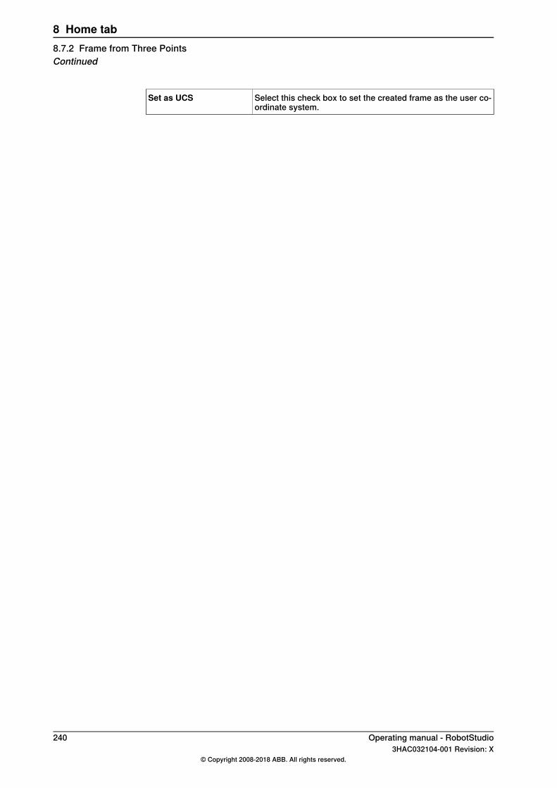
Select this check box to set the created frame as the user co-ordinate system.
Set as UCS
240 Operating manual - RobotStudio3HAC032104-001 Revision: X
© Copyright 2008-2018 ABB. All rights reserved.
8 Home tab8.7.2 Frame from Three PointsContinued
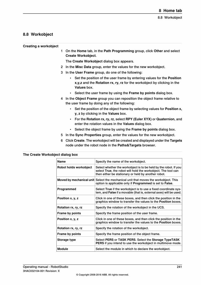
8.8 Workobject
Creating a workobject1 On the Home tab, in the Path Programming group, click Other and select
Create Workobject.The Create Workobject dialog box appears.
2 In the Misc Data group, enter the values for the new workobject.3 In the User Frame group, do one of the following:
• Set the position of the user frame by entering values for the Positionx,y,z and the Rotation rx, ry, rz for the workobject by clicking in theValues box.
• Select the user frame by using the Frame by points dialog box.4 In the Object Frame group you can reposition the object frame relative to
the user frame by doing any of the following:• Set the position of the object frame by selecting values for Position x,
y, z by clicking in the Values box.• For the Rotation rx, ry, rz, select RPY (Euler XYX) or Quaternion, and
enter the rotation values in the Values dialog box.• Select the object frame by using the Frame by points dialog box.
5 In the Sync Properties group, enter the values for the new workobject.6 ClickCreate. The workobject will be created and displayed under the Targets
node under the robot node in the Paths&Targets browser.
The Create Workobject dialog box
Specify the name of the workobject.Name
Select whether the workobject is to be held by the robot. If youselect True, the robot will hold the workobject. The tool canthen either be stationary or held by another robot.
Robot holds workobject
Select the mechanical unit that moves the workobject. Thisoption is applicable only if Programmed is set to False.
Moved bymechanical unit
Select True if the workobject is to use a fixed coordinate sys-tem, and False if a movable (that is, external axes) will be used.
Programmed
Click in one of these boxes, and then click the position in thegraphics window to transfer the values to the Position boxes.
Position x, y, z
Specify the rotation of the workobject in the UCS.Rotation rx, ry, rz
Specify the frame position of the user frame.Frame by points
Click in one of these boxes, and then click the position in thegraphics window to transfer the values to the Position boxes.
Position x, y, z
Specify the rotation of the workobject.Rotation rx, ry, rz
Specify the frame position of the object frame.Frame by points
Select PERS or TASK PERS. Select the Storage TypeTASKPERS if you intend to use the workobject in multimove mode.
Storage type
Select the module in which to declare the workobject.Module
Operating manual - RobotStudio 2413HAC032104-001 Revision: X
© Copyright 2008-2018 ABB. All rights reserved.
8 Home tab8.8 Workobject

8.9 Tooldata
Creating tooldata1 In the Layout browser, make sure the robot in which to create the tooldata
is set as the active task.2 On the Home tab, in the Path Programming group, click Other, and then
click Tooldata.This opens the Create Tooldata dialog box.
3 In the Misc Data group:• Enter the Name of the tool.• Select whether the tool is to be held by the robot in the Robot holds
tool list.4 In the Tool Frame group:
• Define the Position x, y, z of the tool.• Enter the Rotation rx, ry, rz of the tool.
5 In the Load Data group:• Enter the Weight of the tool.• Enter the Center of gravity of the tool.• Enter the Inertia of the tool.
6 In the Sync Properties group:• In the Storage type list, select PERS or TASK PERS. Select TASK
PERS if you intend to use the tooldata in MultiMove mode.• In the Module list, select the module in which to declare the tooldata.
7 Click Create. The tooldata appears as a coordinate system in the graphicswindow.
242 Operating manual - RobotStudio3HAC032104-001 Revision: X
© Copyright 2008-2018 ABB. All rights reserved.
8 Home tab8.9 Tooldata
8.10 Target
8.10.1 Teach Target
Teaching a targetTo teach a target, follow these steps:
1 In the Layout browser, select the workobject and tool for which you want toteach the target.
2 Jog the robot to the preferred position. To jog a robot linearly, its VC mustbe running.
3 Click Teach Target.4 A new target will be created in the browser, under the active workobject node.
In the graphics window a coordinate system will be created at the TCPposition. The configuration of the robot at the target will be saved.
Operating manual - RobotStudio 2433HAC032104-001 Revision: X
© Copyright 2008-2018 ABB. All rights reserved.
8 Home tab8.10.1 Teach Target

8.10.2 Create Target
Creating a target1 In the Layout browser, select the workobject in which you want to create the
target.2 Click Create Target to bring up a dialog box.3 Select the Reference coordinate system you want to use to position the
target:
SelectIf you want to position the target
Worldabsolute in the world coordinate systemof the station
Work Objectrelative to the position of the activeworkobject
UCSin a user-defined coordinate system
4 In the Points box, click Add New and then click the desired position in thegraphics window to set the position of the target. You can also enter thevalues in the Coordinates boxes and click Add.
5 Enter the Orientation for the target. A preliminary cross will be shown in thegraphics window at the selected position. Adjust the position, if necessary.To create the target, click Create.
6 If you want to change the workobject for which the target is to be created,expand the Create Target dialog box by clicking the More button. In theWorkObject list, select the workobject in which you want to create the target.
7 If you want to change the target name from the default name, expand theCreate Target dialog box by clicking the More button and entering the newname in the Target name box.
8 Click Create. The target will appear in the browser and in the graphicswindow.
Note
The created target will not get any configuration for the robot axes. To add theconfiguration values to the target, use either ModPos or the Configurationsdialog box.If using external axes, the position of all activated external axes will be storedin the target.
The Create Target dialog box
Select the reference coordinate system to which all positionsor points will be related.
Reference
Click in one of these boxes, and then click the position in thegraphics window to transfer the values to the Position boxes.
Position
Specify the orientation of the target.Orientation
Continues on next page244 Operating manual - RobotStudio
3HAC032104-001 Revision: X© Copyright 2008-2018 ABB. All rights reserved.
8 Home tab8.10.2 Create Target
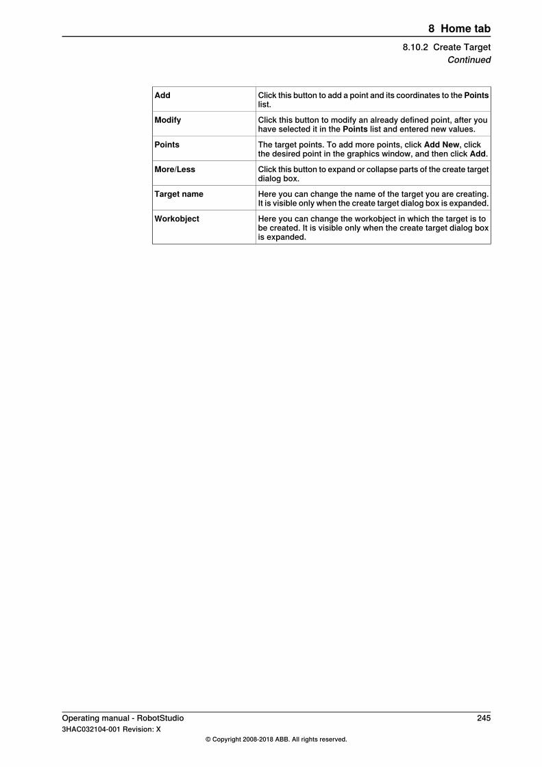
Click this button to add a point and its coordinates to the Pointslist.
Add
Click this button to modify an already defined point, after youhave selected it in the Points list and entered new values.
Modify
The target points. To add more points, click Add New, clickthe desired point in the graphics window, and then click Add.
Points
Click this button to expand or collapse parts of the create targetdialog box.
More/Less
Here you can change the name of the target you are creating.It is visible only when the create target dialog box is expanded.
Target name
Here you can change the workobject in which the target is tobe created. It is visible only when the create target dialog boxis expanded.
Workobject
Operating manual - RobotStudio 2453HAC032104-001 Revision: X
© Copyright 2008-2018 ABB. All rights reserved.
8 Home tab8.10.2 Create Target
Continued

8.10.3 Create Jointtarget
Creating a jointtarget1 Click Create Jointtarget to bring up a dialog box.2 If you want to change the default name of the jointtarget, enter the new name
in the Name box.3 In the Axes Values group, do as follows:
• For theRobot axes, click the Values box and then click the down arrow.The Joint Values dialog box will be displayed. Enter the joint valuesin the boxes and click Accept.
• For the Joint axes, click the Values box and then click the down arrow.The Joint Values dialog box will be displayed. Enter the joint valuesin the boxes and click Accept.
4 Click Create. The jointtarget will appear in the browser and in the graphicswindow.
Note
JointTargets for external axis are not visualized in the graphical window.
The Create Jointtarget dialog box
Specify the name of the jointtarget.Name
Click the Values list, enter the values in the Joint values dialogbox and click Accept.
Robot axes
Click the Values list, enter the values in the Joint values dialogbox and click Accept.
External axes
Select the Storage TypeTASK PERS if you intend to use thejointtarget in multimove mode.
Storage Type
Select the module in which you want to declare the jointtarget.Module
246 Operating manual - RobotStudio3HAC032104-001 Revision: X
© Copyright 2008-2018 ABB. All rights reserved.
8 Home tab8.10.3 Create Jointtarget
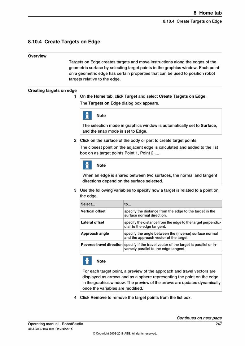
8.10.4 Create Targets on Edge
OverviewTargets on Edge creates targets and move instructions along the edges of thegeometric surface by selecting target points in the graphics window. Each pointon a geometric edge has certain properties that can be used to position robottargets relative to the edge.
Creating targets on edge1 On the Home tab, click Target and select Create Targets on Edge.
The Targets on Edge dialog box appears.
Note
The selection mode in graphics window is automatically set to Surface,and the snap mode is set to Edge.
2 Click on the surface of the body or part to create target points.The closest point on the adjacent edge is calculated and added to the listbox on as target points Point 1, Point 2 ....
Note
When an edge is shared between two surfaces, the normal and tangentdirections depend on the surface selected.
3 Use the following variables to specify how a target is related to a point onthe edge.
to...Select...
specify the distance from the edge to the target in thesurface normal direction.
Vertical offset
specify the distance from the edge to the target perpendic-ular to the edge tangent.
Lateral offset
specify the angle between the (inverse) surface normaland the approach vector of the target.
Approach angle
specify if the travel vector of the target is parallel or in-versely parallel to the edge tangent.
Reverse travel direction
Note
For each target point, a preview of the approach and travel vectors aredisplayed as arrows and as a sphere representing the point on the edgein the graphics window. The preview of the arrows are updated dynamicallyonce the variables are modified.
4 Click Remove to remove the target points from the list box.
Continues on next pageOperating manual - RobotStudio 2473HAC032104-001 Revision: X
© Copyright 2008-2018 ABB. All rights reserved.
8 Home tab8.10.4 Create Targets on Edge
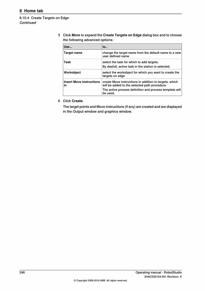
5 Click More to expand the Create Targets on Edge dialog box and to choosethe following advanced options:
to..Use...
change the target name from the default name to a newuser defined name
Target name
select the task for which to add targets.TaskBy deafult, active task in the station is selected.
select the workobject for which you want to create thetargets on edge
Workobject
create Move instructions in addition to targets, whichwill be added to the selected path procedure.
Insert Move Instructionsin
The active process definition and process template willbe used.
6 Click Create.The target points and Move instructions (if any) are created and are displayedin the Output window and graphics window.
248 Operating manual - RobotStudio3HAC032104-001 Revision: X
© Copyright 2008-2018 ABB. All rights reserved.
8 Home tab8.10.4 Create Targets on EdgeContinued
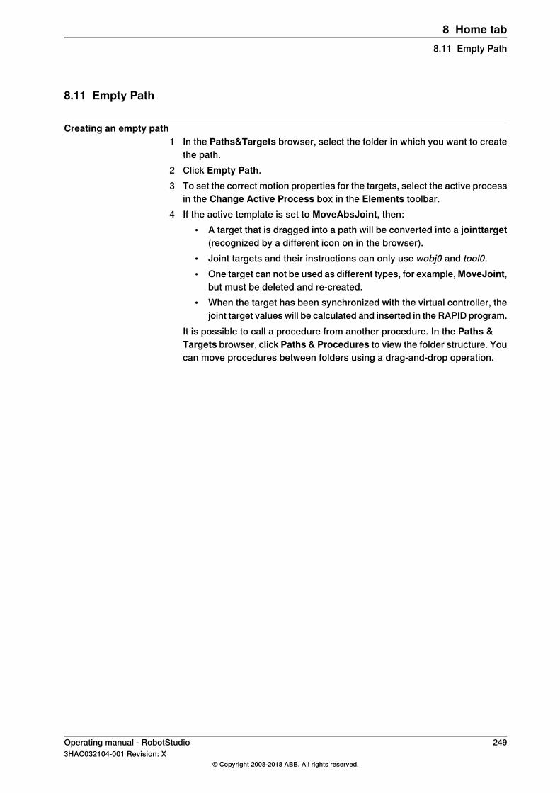
8.11 Empty Path
Creating an empty path1 In the Paths&Targets browser, select the folder in which you want to create
the path.2 Click Empty Path.3 To set the correct motion properties for the targets, select the active process
in the Change Active Process box in the Elements toolbar.4 If the active template is set to MoveAbsJoint, then:
• A target that is dragged into a path will be converted into a jointtarget(recognized by a different icon on in the browser).
• Joint targets and their instructions can only use wobj0 and tool0.• One target can not be used as different types, for example,MoveJoint,
but must be deleted and re-created.• When the target has been synchronized with the virtual controller, the
joint target values will be calculated and inserted in the RAPID program.It is possible to call a procedure from another procedure. In the Paths &Targets browser, click Paths & Procedures to view the folder structure. Youcan move procedures between folders using a drag-and-drop operation.
Operating manual - RobotStudio 2493HAC032104-001 Revision: X
© Copyright 2008-2018 ABB. All rights reserved.
8 Home tab8.11 Empty Path
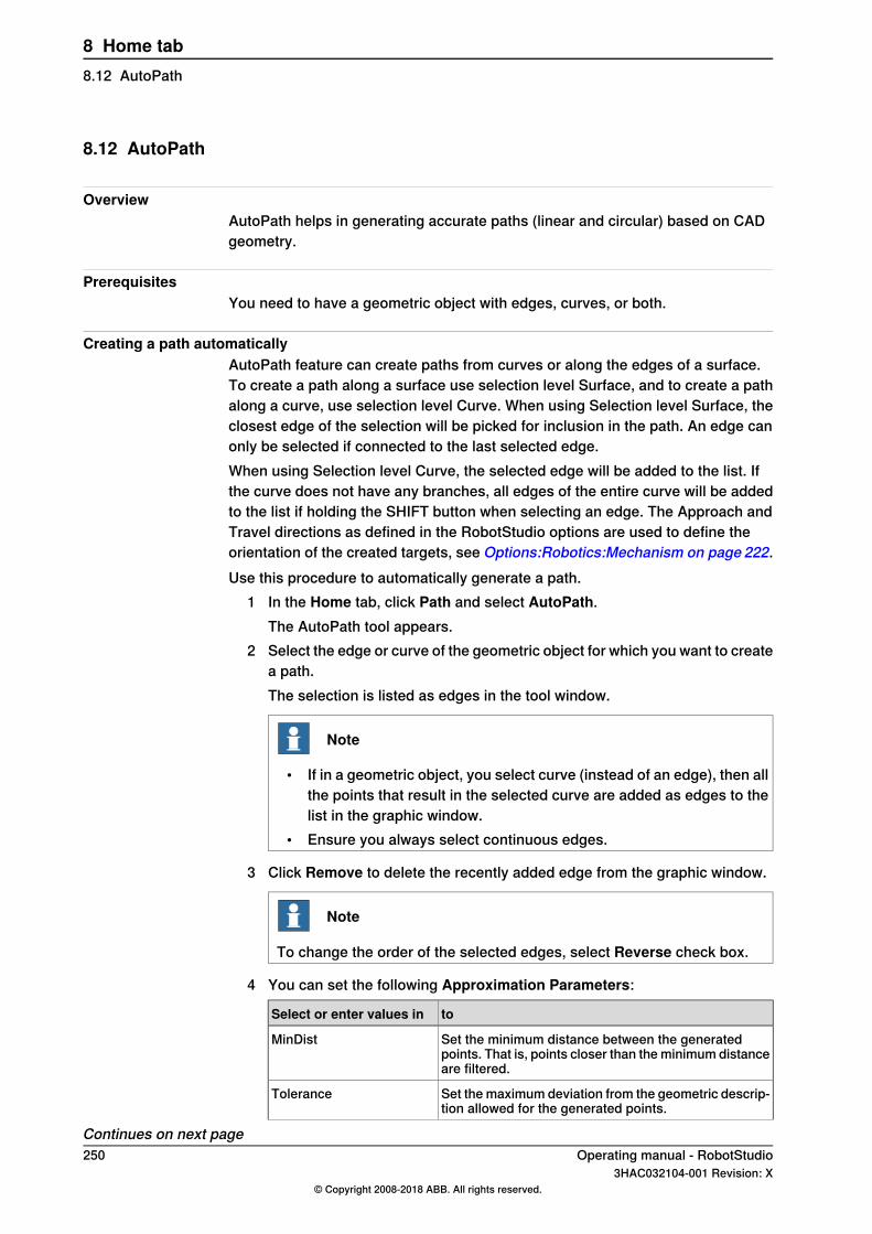
8.12 AutoPath
OverviewAutoPath helps in generating accurate paths (linear and circular) based on CADgeometry.
PrerequisitesYou need to have a geometric object with edges, curves, or both.
Creating a path automaticallyAutoPath feature can create paths from curves or along the edges of a surface.To create a path along a surface use selection level Surface, and to create a pathalong a curve, use selection level Curve. When using Selection level Surface, theclosest edge of the selection will be picked for inclusion in the path. An edge canonly be selected if connected to the last selected edge.When using Selection level Curve, the selected edge will be added to the list. Ifthe curve does not have any branches, all edges of the entire curve will be addedto the list if holding the SHIFT button when selecting an edge. The Approach andTravel directions as defined in the RobotStudio options are used to define theorientation of the created targets, see Options:Robotics:Mechanism on page 222.Use this procedure to automatically generate a path.
1 In the Home tab, click Path and select AutoPath.The AutoPath tool appears.
2 Select the edge or curve of the geometric object for which you want to createa path.The selection is listed as edges in the tool window.
Note
• If in a geometric object, you select curve (instead of an edge), then allthe points that result in the selected curve are added as edges to thelist in the graphic window.
• Ensure you always select continuous edges.
3 Click Remove to delete the recently added edge from the graphic window.
Note
To change the order of the selected edges, select Reverse check box.
4 You can set the following Approximation Parameters:
toSelect or enter values in
Set the minimum distance between the generatedpoints. That is, points closer than the minimum distanceare filtered.
MinDist
Set the maximum deviation from the geometric descrip-tion allowed for the generated points.
Tolerance
Continues on next page250 Operating manual - RobotStudio
3HAC032104-001 Revision: X© Copyright 2008-2018 ABB. All rights reserved.
8 Home tab8.12 AutoPath
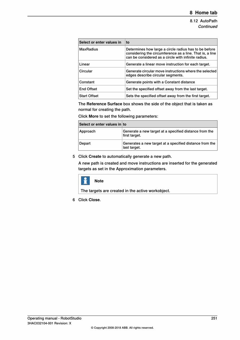
toSelect or enter values in
Determines how large a circle radius has to be beforeconsidering the circumference as a line. That is, a linecan be considered as a circle with infinite radius.
MaxRadius
Generate a linear move instruction for each target.Linear
Generate circular move instructions where the selectededges describe circular segments.
Circular
Generate points with a Constant distanceConstant
Set the specified offset away from the last target.End Offset
Sets the specified offset away from the first target.Start Offset
The Reference Surface box shows the side of the object that is taken asnormal for creating the path.Click More to set the following parameters:
toSelect or enter values in
Generate a new target at a specified distance from thefirst target.
Approach
Generates a new target at a specified distance from thelast target.
Depart
5 Click Create to automatically generate a new path.A new path is created and move instructions are inserted for the generatedtargets as set in the Approximation parameters.
Note
The targets are created in the active workobject.
6 Click Close.
Operating manual - RobotStudio 2513HAC032104-001 Revision: X
© Copyright 2008-2018 ABB. All rights reserved.
8 Home tab8.12 AutoPath
Continued

8.13 MultiMove
OverviewFor browsing between the pages of the MultiMove window, click the tabs in thenavigation pane. By default the tabs are arranged in an order that corresponds tothe typical workflow:
Setup tab
Here you select the system that con-tains the robots to program.
Select SystemSystemCon-fig
Each robot in the system is presentedin its own row in this grid. In thecolumns you make the settings asdescribed below.
System
Select this check box to use the robotin the MultiMove program.
Enable
Specify if the robot holds the tool orthe work piece.
Type
Displays the name of the robot.Robot
Click this button to update the pathsin the grid if any of the paths havebeen changed. The button turns redif a change has been detected and anupdate is necessary.
UpdatePath Config
Each path in the station is presentedin its own row in this grid. In thecolumns you make the settings asdescribed below.
Paths
Select this check box for the paths touse for the program.
Enable
Displays the order in which the pathswill be executed. To change the order,use the lists in the path column forrearranging the rows in which thepaths appear.
Order
Sets the path to be executed here.Path
When creating a new start position,select a robot that the other will try toreach here.
Select Robot that other shall jump toStart Posi-tion
Jumps the other robots to the newstart position.
Apply
Motion Behavior tabThis is used for specifying constraints and rules for how the robots shall moverelative to each other. The default setting is no particular constraints, which resultsin the fewest joint movements. However, changing the motion behavior might beuseful for:
• Locking the orientation or position of the tool.• Optimizing cycle time or reachability by allowing tolerances.
Continues on next page252 Operating manual - RobotStudio
3HAC032104-001 Revision: X© Copyright 2008-2018 ABB. All rights reserved.
8 Home tab8.13 MultiMove

• Avoiding collisions or singularity by restricting joint motions.Both Joint Influence and TCP Constraints restrict the robot’s motions. Changes inthese settings might result in lower performance or situations where it is impossibleto find proper solutions. The weight values for Joint Weights and TCP Constraintsset how much the setting for each joint or TCP direction shall affect the robotsrelative to each other. It is the difference between the weight values that matters,not the absolute values. If contradicting behaviors have been set, the one with thelowest weight value will win.Tool Tolerance, instead of restricting, enables more motions. Therefore, tolerancesmay improve cycle and process times and enhance the reachability of the robots.Tolerances, too, have weight value; here is set how much the robots shall use thetolerance. A low value indicates that the tolerance will be used a lot, while a highvalue means that the robots will try to avoid using the tolerance.The joint influence controls the balance of how much the robots will use their joints.Decreasing the weight value for one axis will restrict the motion for this axis, whileincreasing it will promote motion on this axis relative to alternative axes.The TCP constraints control the position and orientation of the tool. Enabling aTCP constraint will decrease the motion of the tool and increase the motion of thework piece.The tool tolerances control the allowed deviation between the tool and the workpiece. By default, tolerances are not enabled, which means that no deviation isallowed. Enabling a tolerance, if applicable, might improve motion performance.For example, if the tool is symmetric around its Z axis, you can enable the Rztolerance without affecting the accuracy of the generated paths.The tool offset sets a fixed distance between the tool and the paths.
Select the robot’s joints to constrainin this box.
Select RobotJoint Influ-ence
Displays the robot’s joints and theirconstraint weights. Each joint ispresented in its own row.
Joints for Robot
Displays which axis the constraint af-fects.
Axis
Specify how much the motion for theaxis is constrained. 0 means a lockedaxis, while 100 means no constraintrelative to default constraint values.
Influence
This grid displays the position and ro-tations of the TCP together with theirconstraint weights.
Active TCPTCP Con-straints
Select this check box to activate theconstraint for this TCP pose.
Enable
Displays the TCP pose that is affectedby the constraint.
Pose
Specify the pose value to constrain at.Either type the value, or click the Pickfrom TCP button to use the values ofthe current TCP position.
Value
Continues on next pageOperating manual - RobotStudio 2533HAC032104-001 Revision: X
© Copyright 2008-2018 ABB. All rights reserved.
8 Home tab8.13 MultiMove
Continued

Specify how much the motion for theTCP value is constrained. 0 means alocked TCP at this pose, while 100means no constraint relative to defaultconstraint values.
Influence
Select this check box to activate thetolerance for this tool pose.
EnableTool Toler-ance
Displays the tool pose that is affectedby the constraint.
Pose
Specify the pose value to apply thetolerance around.
Value
Specify the size of the tolerance. 0means no deviation is allowed, while100 means all deviations are allowed.
Influence
Select this check box to activate theoffset for this tool pose.
EnableTool Offset
Displays the tool pose that is affectedby the offset setting.
Pose
Specify the value of the offset here.Offset
Create Paths tabThis tab is used for creating RobotStudio paths for the MultiMove robots. Thecreated paths will accord with the motions displayed during the most recentlyplayed test simulation.With the settings group you set up the MultiMove properties that connect the tasksfor the tool robot and work piece robot to each other.With the WP robot settings group you set up the properties for the task that will begenerated for the work piece robot.The generate path group contains the button that creates the paths.
Specify the first ID number for thesynchronization of the instructions forthe robots.
Start IDSettings
Specify the gap between the succeed-ing ID numbers.
ID step index
Specify a prefix for the syncidentvariable, which connects the sync in-structions in the tasks for the tool ro-bot and the work piece robot with eachother.
Sync ident prefix
Specify a prefix for the tasklist vari-able, which identifies the tasks for thetool robot and work piece robot tosynchronize.
Task list prefix
Specify a prefix for the generatedpaths.
Path Prefix
Specify a prefix for the generated tar-gets.
Target Prefix
Specify the work object to which thetargets generated for the work piecerobot shall belong.
WP WorkobjectWP robotsettings
Continues on next page254 Operating manual - RobotStudio
3HAC032104-001 Revision: X© Copyright 2008-2018 ABB. All rights reserved.
8 Home tab8.13 MultiMoveContinued
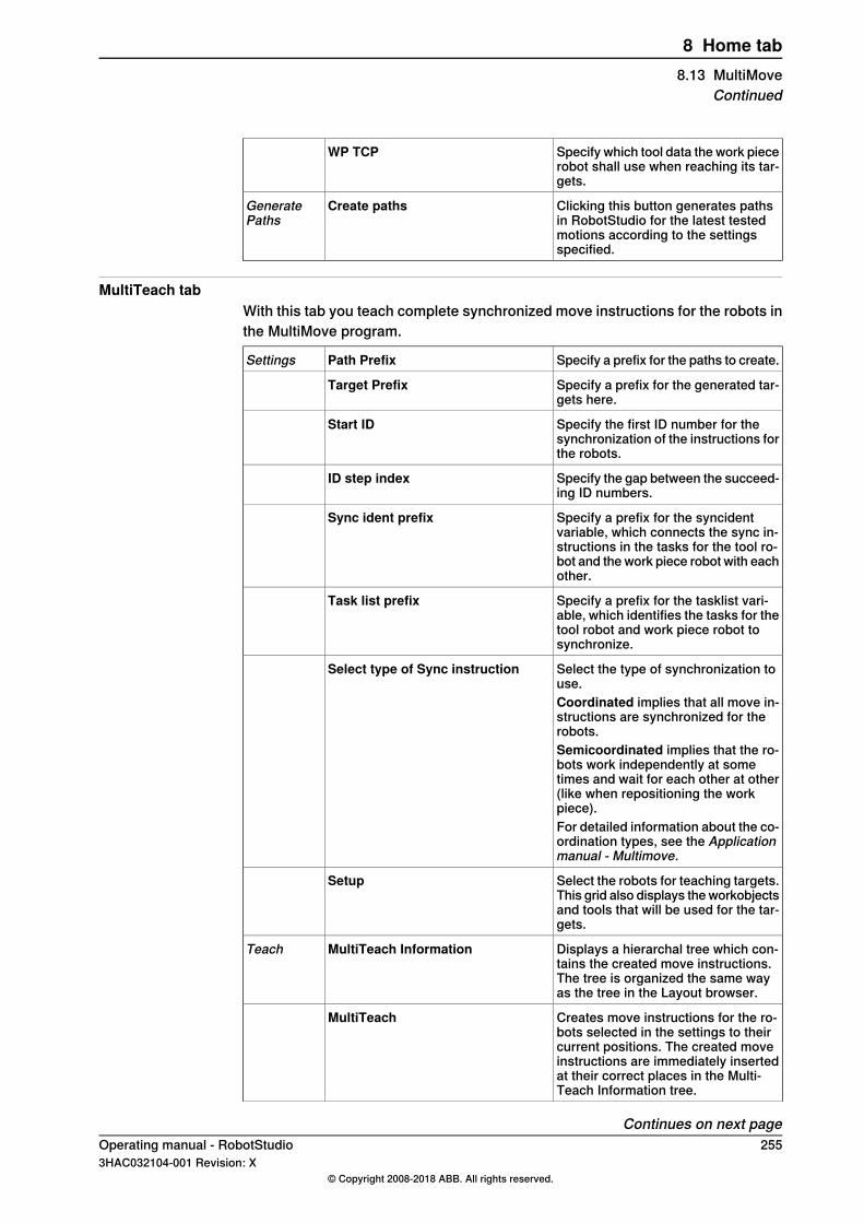
Specify which tool data the work piecerobot shall use when reaching its tar-gets.
WP TCP
Clicking this button generates pathsin RobotStudio for the latest testedmotions according to the settingsspecified.
Create pathsGeneratePaths
MultiTeach tabWith this tab you teach complete synchronized move instructions for the robots inthe MultiMove program.
Specify a prefix for the paths to create.Path PrefixSettings
Specify a prefix for the generated tar-gets here.
Target Prefix
Specify the first ID number for thesynchronization of the instructions forthe robots.
Start ID
Specify the gap between the succeed-ing ID numbers.
ID step index
Specify a prefix for the syncidentvariable, which connects the sync in-structions in the tasks for the tool ro-bot and the work piece robot with eachother.
Sync ident prefix
Specify a prefix for the tasklist vari-able, which identifies the tasks for thetool robot and work piece robot tosynchronize.
Task list prefix
Select the type of synchronization touse.
Select type of Sync instruction
Coordinated implies that all move in-structions are synchronized for therobots.Semicoordinated implies that the ro-bots work independently at sometimes and wait for each other at other(like when repositioning the workpiece).For detailed information about the co-ordination types, see the Applicationmanual - Multimove.
Select the robots for teaching targets.This grid also displays the workobjectsand tools that will be used for the tar-gets.
Setup
Displays a hierarchal tree which con-tains the created move instructions.The tree is organized the same wayas the tree in the Layout browser.
MultiTeach InformationTeach
Creates move instructions for the ro-bots selected in the settings to theircurrent positions. The created moveinstructions are immediately insertedat their correct places in the Multi-Teach Information tree.
MultiTeach
Continues on next pageOperating manual - RobotStudio 2553HAC032104-001 Revision: X
© Copyright 2008-2018 ABB. All rights reserved.
8 Home tab8.13 MultiMove
Continued

Confirms the creation of the instruc-tions.
Done
Test tabRobotStudio’s MultiMove window has a page with commands for testing multimoveprograms. Its default placement is at the bottom of the MultiMove window.The status group displays the status of the simulation, that is, whether the currentsettings have been tested or if errors have occurred.In addition to the status group, information from the virtual controller is alsodisplayed in RobotStudio’s Output window during simulation.
Jumps the robots, respectively, to theprevious and next targets in paths.The double arrow buttons jump sever-al targets at once, while the single ar-row buttons jump one target for eachclick.
<< < > >>Play
Click this button to move the robotsalong the paths.
Play
Play also has a list box in which youcan activate the following commands:
• Save current position: Savesthe current start position. Sincethe calculated motions arebased on the robot start posi-tion saving the start position isuseful when testing alternativesolutions.
• Restore saved position: Movesthe robots back to the savedstart positions.
• Restore last closed loop posi-tion: Moves the robots back tothe list used start position.
• Close loop: Finds a suitablestart position based on the ro-bots’ current positions andprepares the calculation ofmovements.
• Calculate: Calculates and ex-ecutes the movements.
Sets the speed at which the simulationis performed.
Simulation speed
Select this check box to make thesimulation stop after running the pathsone time. If cleared, the simulation willcontinue playing over and over until itis stopped manually.
Stop at endSettings
Select this check box to run the simu-lation as the movements are calcu-lated.
Simulate Online
This is useful for troubleshooting pur-poses, since it displays and reportstargets the robot cannot reach.
Continues on next page256 Operating manual - RobotStudio
3HAC032104-001 Revision: X© Copyright 2008-2018 ABB. All rights reserved.
8 Home tab8.13 MultiMoveContinued
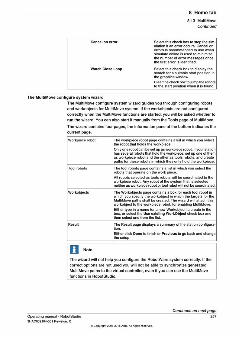
Select this check box to stop the sim-ulation if an error occurs. Cancel onerrors is recommended to use whensimulate online is used to minimizethe number of error messages oncethe first error is identified.
Cancel on error
Select this check box to display thesearch for a suitable start position inthe graphics window.
Watch Close Loop
Clear the check box to jump the robotsto the start position when it is found.
The MultiMove configure system wizardThe MultiMove configure system wizard guides you through configuring robotsand workobjects for MultiMove system. If the workobjects are not configuredcorrectly when the MultiMove functions are started, you will be asked whether torun the wizard. You can also start it manually from the Tools page of MultiMove.The wizard contains four pages, the information pane at the bottom indicates thecurrent page.
The workpiece robot page contains a list in which you selectthe robot that holds the workpiece.
Workpiece robot
Only one robot can be set up as workpiece robot. If your stationhas several robots that hold the workpiece, set up one of themas workpiece robot and the other as tools robots, and createpaths for these robots in which they only hold the workpiece.
The tool robots page contains a list in which you select therobots that operate on the work piece.
Tool robots
All robots selected as tools robots will be coordinated to theworkpiece robot. Any robot of the system that is selectedneither as workpiece robot or tool robot will not be coordinated.
The Workobjects page contains a box for each tool robot inwhich you specify the workobject in which the targets for theMultiMove paths shall be created. The wizard will attach thisworkobject to the workpiece robot, for enabling MutliMove.
Workobjects
Either type in a name for a new Workobject to create in thebox, or select the Use existing WorkObject check box andthen select one from the list.
The Result page displays a summary of the station configura-tion.
Result
Either click Done to finish or Previous to go back and changethe setup.
Note
The wizard will not help you configure the RobotWare system correctly. If thecorrect options are not used you will not be able to synchronize generatedMultiMove paths to the virtual controller, even if you can use the MultiMovefunctions in RobotStudio.
Continues on next pageOperating manual - RobotStudio 2573HAC032104-001 Revision: X
© Copyright 2008-2018 ABB. All rights reserved.
8 Home tab8.13 MultiMove
Continued

The Analyze path toolThis tool checks whether existing paths are coordinated correctly for MultiMove.The analyzer opens in a window of its own and contains three pages. Theinformation pane at the bottom indicates the current page.
Select to include the task in the ana-lysis.
EnableSelect Paths
Displays the name of the task.Task
Select the path to analyze for the cur-rent task.
Path
Click this button to start the analysis.AnalyzeAnalyze
OK. The paths are compatible in thespecified aspect.
reportok
Report
Information. The paths are not fullycompatible in the specified aspect, butthe robot program may still be execut-able.
reportin
Error. The paths are not compatible inthe specified aspect, and the robotprogram is not executable.reporter
The Recalculate ID toolThis is one of the tools for working manually with MultiMove programs. It sets newsync ID arguments to the move instructions in a MultiMove path. By using the toolwith the same start ID and ID step index on all paths that shall be synchronized,you can be sure that the IDs match if all paths contain the same number of moveinstructions.
Displays the name of the path to recalculate IDs for.Title
Sets the number of the first ID in the path.Start ID
Sets the size of the step to increase the ID number for eachmove instruction.
ID Step index
Select this check box to recalculate only those IDs for instruc-tions that have existing IDs.
Only update instructionsthat has ID defined
Clear this check box to also create IDs for instructions thathave no IDs (for example, if you have added new move instruc-tions that shall be coordinated).
Select this check box to affect only those move instructionsthat belong to already synchronized parts of the path.
The Only update instruc-tions between SyncMoveOn/Off check box. Clear this check box to update IDs for instructions in all parts
of the path.
Continues on next page258 Operating manual - RobotStudio
3HAC032104-001 Revision: X© Copyright 2008-2018 ABB. All rights reserved.
8 Home tab8.13 MultiMoveContinued
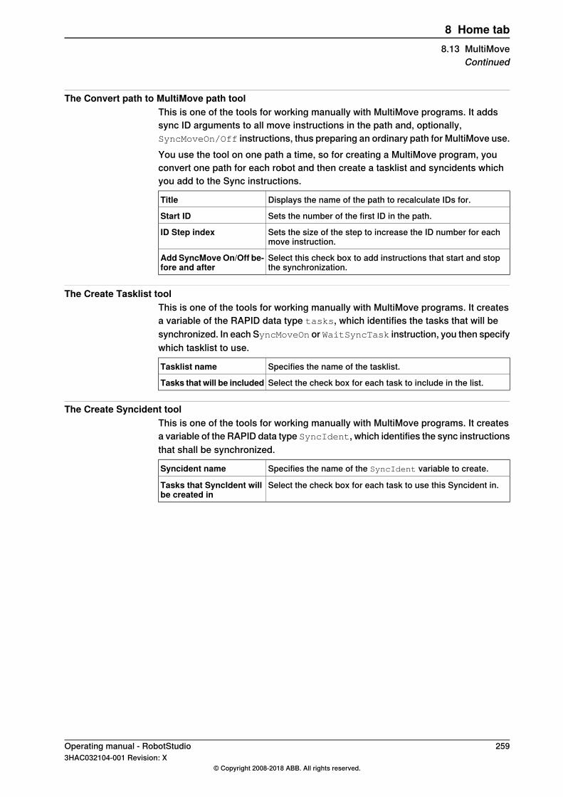
The Convert path to MultiMove path toolThis is one of the tools for working manually with MultiMove programs. It addssync ID arguments to all move instructions in the path and, optionally,SyncMoveOn/Off instructions, thus preparing an ordinary path for MultiMove use.You use the tool on one path a time, so for creating a MultiMove program, youconvert one path for each robot and then create a tasklist and syncidents whichyou add to the Sync instructions.
Displays the name of the path to recalculate IDs for.Title
Sets the number of the first ID in the path.Start ID
Sets the size of the step to increase the ID number for eachmove instruction.
ID Step index
Select this check box to add instructions that start and stopthe synchronization.
Add SyncMoveOn/Off be-fore and after
The Create Tasklist toolThis is one of the tools for working manually with MultiMove programs. It createsa variable of the RAPID data type tasks, which identifies the tasks that will besynchronized. In each SyncMoveOn or WaitSyncTask instruction, you then specifywhich tasklist to use.
Specifies the name of the tasklist.Tasklist name
Select the check box for each task to include in the list.Tasks that will be included
The Create Syncident toolThis is one of the tools for working manually with MultiMove programs. It createsa variable of the RAPID data type SyncIdent, which identifies the sync instructionsthat shall be synchronized.
Specifies the name of the SyncIdent variable to create.Syncident name
Select the check box for each task to use this Syncident in.Tasks that SyncIdent willbe created in
Operating manual - RobotStudio 2593HAC032104-001 Revision: X
© Copyright 2008-2018 ABB. All rights reserved.
8 Home tab8.13 MultiMove
Continued

8.14 Teach Instruction
Teaching a move instruction1 In the Layout browser, make sure the settings for active robot, workobject,
tool, motion type and path are appropriate for the move instruction to create.2 Jog the robot to the desired location. If jogging the robot using the freehand
mode, you can also use snap modes for snapping its TCP to objects in thestation.
3 Click Teach Instruction. A move instruction is now created last in the path.
260 Operating manual - RobotStudio3HAC032104-001 Revision: X
© Copyright 2008-2018 ABB. All rights reserved.
8 Home tab8.14 Teach Instruction
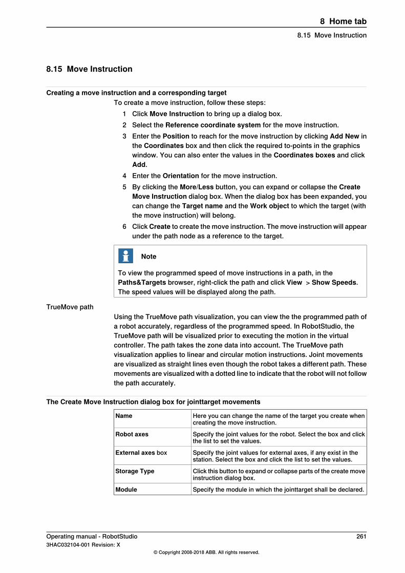
8.15 Move Instruction
Creating a move instruction and a corresponding targetTo create a move instruction, follow these steps:
1 Click Move Instruction to bring up a dialog box.2 Select the Reference coordinate system for the move instruction.3 Enter the Position to reach for the move instruction by clicking Add New in
the Coordinates box and then click the required to-points in the graphicswindow. You can also enter the values in the Coordinates boxes and clickAdd.
4 Enter the Orientation for the move instruction.5 By clicking the More/Less button, you can expand or collapse the Create
Move Instruction dialog box. When the dialog box has been expanded, youcan change the Target name and the Work object to which the target (withthe move instruction) will belong.
6 ClickCreate to create the move instruction. The move instruction will appearunder the path node as a reference to the target.
Note
To view the programmed speed of move instructions in a path, in thePaths&Targets browser, right-click the path and click View > Show Speeds.The speed values will be displayed along the path.
TrueMove pathUsing the TrueMove path visualization, you can view the the programmed path ofa robot accurately, regardless of the programmed speed. In RobotStudio, theTrueMove path will be visualized prior to executing the motion in the virtualcontroller. The path takes the zone data into account. The TrueMove pathvisualization applies to linear and circular motion instructions. Joint movementsare visualized as straight lines even though the robot takes a different path. Thesemovements are visualized with a dotted line to indicate that the robot will not followthe path accurately.
The Create Move Instruction dialog box for jointtarget movements
Here you can change the name of the target you create whencreating the move instruction.
Name
Specify the joint values for the robot. Select the box and clickthe list to set the values.
Robot axes
Specify the joint values for external axes, if any exist in thestation. Select the box and click the list to set the values.
External axes box
Click this button to expand or collapse parts of the create moveinstruction dialog box.
Storage Type
Specify the module in which the jointtarget shall be declared.Module
Operating manual - RobotStudio 2613HAC032104-001 Revision: X
© Copyright 2008-2018 ABB. All rights reserved.
8 Home tab8.15 Move Instruction
8.16 Action Instruction
Creating an action instruction1 In the Paths&Targets browser, select where to insert the action instruction.
To insert the action instruction at the beginning of a path then select thepath.To insert the action instruction after another instruction then select theproceeding instruction.
2 Right click Path and select Insert Action Instruction.The Create Action Instruction dialog box appears.
3 From the Instruction Templates list, select the action instruction to create.4 Optionally, modify instruction arguments in the Instruction Arguments grid.
For detailed information about the arguments for each instruction, see theAction Instruction on page 262.
5 Click Create.
262 Operating manual - RobotStudio3HAC032104-001 Revision: X
© Copyright 2008-2018 ABB. All rights reserved.
8 Home tab8.16 Action Instruction

8.17 Instruction Template Manager
OverviewUse Instruction Template Manager to support instructions other than RobotStudio'sdefault instructions set, for example, certain instructions like DispL and DispC areinstructions used for glueing by a robot controller system with the RobotWareDispense option. You can manually define the instruction templates for suchinstructions using the Instruction Template Manager. These instruction templatesare exported to XML format and reused later.RobotStudio provides pre-defined XML files that can be imported and used forrobot controller systems with certain RobotWare options. For example, it isrecommended to use RobotStudio ArcWelding PowerPac while using RobotWareArc. The instruction template supports Robotware options like ContinuousApplication Protocol (CAP), Dispense (Disp), Fixed Position Events (Trigg), SpotPneumatic, Spot Servo, Spot Servo Equalizing, Paint, Multimove Coordinated andConveyor Tracking. When you start a new system, default instruction templatesare loaded. When starting a system with one or more of these options, thecorresponding instruction templates are added automatically.
Instruction Template ManagerYou can use Instruction Template Manager to define instruction templates. In theHome tab, in Path Programming group, click the arrow next to Multimove to openthe Instruction Template Manager pane. The Instruction Template Managerwindow consists of two panes. The names of Move and Action instructions appearin one pane and the arguments of the selected instruction in the other pane. Youcan select the required instruction and set the arguments to customize yourinstruction template.The customized instruction template can be exported to *xml format and can beimported and reused later. Use various buttons provided in the Instruction TemplateManager window to add or delete Move and Action instructions. You can importor export the selected template or export all instruction templates here.
Operating manual - RobotStudio 2633HAC032104-001 Revision: X
© Copyright 2008-2018 ABB. All rights reserved.
8 Home tab8.17 Instruction Template Manager

8.18 Settings
8.18.1 Task
Selecting a TaskSelect a task from the Task drop-down list. The selected task indicates active task,to which new workobjects, tooldata, target, empty path or path from curve will beadded.
264 Operating manual - RobotStudio3HAC032104-001 Revision: X
© Copyright 2008-2018 ABB. All rights reserved.
8 Home tab8.18.1 Task

8.18.2 Workobject
Selecting a WorkobjectSelect a workobject from the Workobject drop-down list. The selected workobjectindicates active workobject, to which new targets and move instructions are added.
Operating manual - RobotStudio 2653HAC032104-001 Revision: X
© Copyright 2008-2018 ABB. All rights reserved.
8 Home tab8.18.2 Workobject

8.18.3 Tool
Selecting a ToolSelect a tool from the Tool drop-down list. The selected tool indicates active tool,to which move instructions are added.
266 Operating manual - RobotStudio3HAC032104-001 Revision: X
© Copyright 2008-2018 ABB. All rights reserved.
8 Home tab8.18.3 Tool
8.19 The Freehand Group
Move1 In the Layout browser, select the item you want to move.2 Click Move.3 In the graphics window, click one of the axes and drag the item into position.
Continues on next pageOperating manual - RobotStudio 2673HAC032104-001 Revision: X
© Copyright 2008-2018 ABB. All rights reserved.
8 Home tab8.19 The Freehand Group
8.19.1 Rotate
Rotating an item1 In the Layout browser, select the item you want to rotate.2 Click Rotate.3 In the graphics window, click one of the rotational rings and drag the item
into position.If you press the ALT key while rotating, the item will snap 10 degrees at atime.
268 Operating manual - RobotStudio3HAC032104-001 Revision: X
© Copyright 2008-2018 ABB. All rights reserved.
8 Home tab8.19.1 Rotate
8.19.2 Jog Joint
Jogging the joints of a robot1 In the Layout browser, select the robot you want to move.2 Click Jog Joint.3 Click the joint you want to move and drag it to the preferred position.
If you press the ALT key when jogging the joints of the robot, the robot willmove 10 degrees at a time. If you press the f key, the robot will move 0.1degree at a time.
Operating manual - RobotStudio 2693HAC032104-001 Revision: X
© Copyright 2008-2018 ABB. All rights reserved.
8 Home tab8.19.2 Jog Joint
8.19.3 Jog Linear
Jogging the TCP of a robot1 In the Layout browser, select the robot you want to move.2 In the Freehand group, click Jog Linear. A coordinate system will be
displayed at the TCP of the robot.3 Click the axis you want to move and drag the TCP to the preferred position.
If you press the f key while jogging the robot linearly, the robot will movewith a smaller step size.
270 Operating manual - RobotStudio3HAC032104-001 Revision: X
© Copyright 2008-2018 ABB. All rights reserved.
8 Home tab8.19.3 Jog Linear

8.19.4 Jog Reorient
Reorienting the TCP rotation1 In the Layout browser, select the robot you want to reorient.2 In the Freehand group, click Jog Reorient.
An orientation ring appears around the TCP.3 Click the orientation ring and drag the robot to rotate the TCP to the preferred
position.The X, Y, and Z orientation appears with units.
Note
If you press the ALT key while reorienting, the robot moves by 10 unitsand if you press the F key, it moves by 0.1 unit.
Note
The behavior of orientation differs with the different reference coordinatesystem (World, Local, UCS, Active Workobject, Active Tool).
Operating manual - RobotStudio 2713HAC032104-001 Revision: X
© Copyright 2008-2018 ABB. All rights reserved.
8 Home tab8.19.4 Jog Reorient
8.19.5 MultiRobot Jog
Jogging robots in multirobot mode1 In the Freehand group, click MultiRobot Jog. Select the robots to be jogged
from the list of available robots.2 Select the jogging mode, jog one of the robots and the other ones will follow
the movement.
272 Operating manual - RobotStudio3HAC032104-001 Revision: X
© Copyright 2008-2018 ABB. All rights reserved.
8 Home tab8.19.5 MultiRobot Jog
8.20 Graphics Tools
OverviewThe Graphics Tools helps you to control the graphics view and to modify theappearance of objects. All available options are grouped under the following tabs.
• View Tab• Edit Tab
Continues on next pageOperating manual - RobotStudio 2733HAC032104-001 Revision: X
© Copyright 2008-2018 ABB. All rights reserved.
8 Home tab8.20 Graphics Tools
8.20.1 View Tab
IntroductionUse the View tab to choose view settings, control graphics view and create newviews, and to show/hide the selected targets, frames, paths, parts, and mechanisms.The View tab options are grouped under the following groups.
• View• Navigate• Markups• Lights• Clip Planes• Freehand• Close
View Group
IntroductionThe View group helps you to choose view settings, control graphics view andcreate new views, and to show/hide the selected targets, frames, paths, parts, andmechanisms.The following options are available:
• New View• View Settings : Projection, Representation, Frame Size• Settings• Advanced Lighting• Show/Hide• Automatic Transparency• Statistics• Stereo Mode
Select New View to create a new view.
View SettingsYou can select the following different view settings.
DescriptionSetting
To view the orthographic and perspective view of the object.Projection• Orthographic• Perspective
To view the objects as a surface, wireframe, both surfaceand wireframe, by removing hidden lines.
Representation• Surface• Wireframe• Both• Hidden-line removal
To view the frame in large, medium and small sizes.Frame Size• Large• Medium• Small
Continues on next page274 Operating manual - RobotStudio
3HAC032104-001 Revision: X© Copyright 2008-2018 ABB. All rights reserved.
8 Home tab8.20.1 View Tab
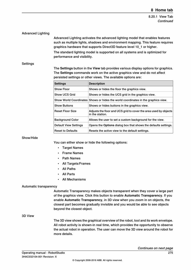
Advanced LightingAdvanced Lighting activates the advanced lighting model that enables featuressuch as multiple lights, shadows and environment mapping. This feature requiresgraphics hardware that supports Direct3D feature level 10_1 or higher.The standard lighting model is supported on all systems and is optimized forperformance and visibility.
SettingsThe Settings button in the View tab provides various display options for graphics.The Settings commands work on the active graphics view and do not affectpersisted settings or other views. The available options are:
DescriptionSettings
Shows or hides the floor the graphics view.Show Floor
Shows or hides the UCS grid in the graphics view.Show UCS Grid
Shows or hides the world coordinates in the graphics view.Show World Coordinates
Shows or hides buttons in the graphics view.Show Buttons
Adjusts the floor and UCS grid to cover the area used by objectsin the station.
Reset Floor Size
Allows the user to set a custom background for the view.Background Color
Opens the Options dialog box that shows the defaults settings.Default View Settings
Resets the active view to the default settings.Reset to Defaults
Show/HideYou can either show or hide the following options:
• Target Names• Frame Names• Path Names• All Targets/Frames• All Paths• All Parts• All Mechanisms
Automatic transparencyAutomatic Transparency makes objects transparent when they cover a large partof the graphics view. Click this button to enable Automatic Transparency. If youenable Automatic Transparency, in 3D view when you zoom in on objects, theclosest part becomes gradually invisible and you would be able to see objectsbeyond the closest object.
3D ViewThe 3D view shows the graphical overview of the robot, tool and its work envelope.All robot activity is shown-in real time, which provides the opportunity to observethe actual robot in operation. The user can move the 3D view around the robot formore details.
Continues on next pageOperating manual - RobotStudio 2753HAC032104-001 Revision: X
© Copyright 2008-2018 ABB. All rights reserved.
8 Home tab8.20.1 View Tab
Continued
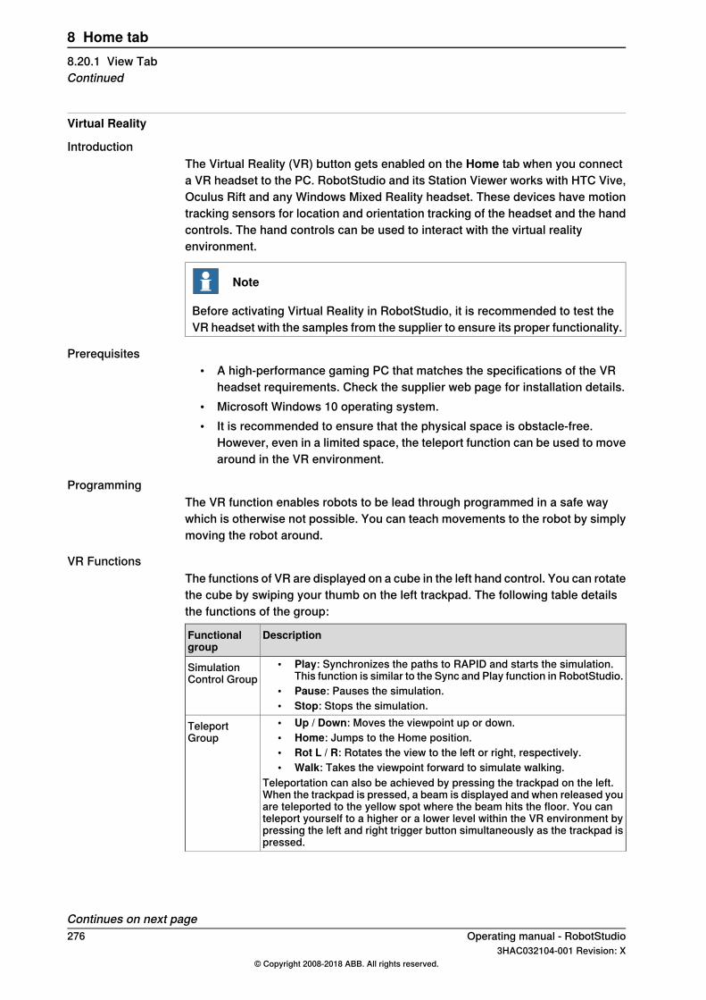
Virtual Reality
IntroductionThe Virtual Reality (VR) button gets enabled on the Home tab when you connecta VR headset to the PC. RobotStudio and its Station Viewer works with HTC Vive,Oculus Rift and any Windows Mixed Reality headset. These devices have motiontracking sensors for location and orientation tracking of the headset and the handcontrols. The hand controls can be used to interact with the virtual realityenvironment.
Note
Before activating Virtual Reality in RobotStudio, it is recommended to test theVR headset with the samples from the supplier to ensure its proper functionality.
Prerequisites• A high-performance gaming PC that matches the specifications of the VR
headset requirements. Check the supplier web page for installation details.• Microsoft Windows 10 operating system.• It is recommended to ensure that the physical space is obstacle-free.
However, even in a limited space, the teleport function can be used to movearound in the VR environment.
ProgrammingThe VR function enables robots to be lead through programmed in a safe waywhich is otherwise not possible. You can teach movements to the robot by simplymoving the robot around.
VR FunctionsThe functions of VR are displayed on a cube in the left hand control. You can rotatethe cube by swiping your thumb on the left trackpad. The following table detailsthe functions of the group:
DescriptionFunctionalgroup
• Play: Synchronizes the paths to RAPID and starts the simulation.This function is similar to the Sync and Play function in RobotStudio.
• Pause: Pauses the simulation.• Stop: Stops the simulation.
SimulationControl Group
• Up / Down: Moves the viewpoint up or down.• Home: Jumps to the Home position.• Rot L / R: Rotates the view to the left or right, respectively.• Walk: Takes the viewpoint forward to simulate walking.
Teleportation can also be achieved by pressing the trackpad on the left.When the trackpad is pressed, a beam is displayed and when released youare teleported to the yellow spot where the beam hits the floor. You canteleport yourself to a higher or a lower level within the VR environment bypressing the left and right trigger button simultaneously as the trackpad ispressed.
TeleportGroup
Continues on next page276 Operating manual - RobotStudio
3HAC032104-001 Revision: X© Copyright 2008-2018 ABB. All rights reserved.
8 Home tab8.20.1 View TabContinued

DescriptionFunctionalgroup
• Text: Adds a markup with the name of the user and a number. Themarkup text can be modified from RobotStudio.
• Arrow: Adds an arrow.• Draw: For freeform scribbling.
AnnotateGroup
• Camera: Displays the outside view from camera.• Grab: Allows the parts to be moved.
Misc Group
• Jog: Jog the robot jointwise by dragging its links or linearly bydragging its tool.
• Undo / Redo: Reverts or repeats previous operation.
Interact Group
• Paths: To enter the modification mode. Opens a menu with additionalfunctions on the right-hand side. Select a robtarget to modify it.
- Robot follows: The robot follows the target when modified,c.f. View robot at target in RobotStudio.
- Translate: Allows the translation to be modified.- Reorient: Allows the rotation to be modified.- Finetune: Scales down the modification of the robtarget by a
factor of 10, i.e moving the hand-control by 10 moves theselected target by 1 .
• Teach: To enter the teach mode. Opens a menu with additionalfunctions on the right-hand side. You can select the path in whichthe instruction should be inserted. For example, Path10 and the in-struction template to be used, like MoveL.The right-hand trigger button can be used to jog the robot and theleft button can be used to insert new targets while jogging. You candelete a target by pointing at it and double-clicking the grip button.
- Add: Adds a target at the location of the TCP.- Record: Records the motion of the hand control and converts
it into a robot path.• Speed: To enter the speed modification mode. When you select a
motion segment, a list of the available speed data is displayed. Youcan scroll through the available parameters and select the preferredone.
• Zone: To enter the zone modification mode. When you select a target,a list of the available zone data is displayed in a scrollable list.
• Configuration: To enter the configuration modification mode. Whenyou select a target, the available configurations are displayed.
• Brush: Brush instructions (SetBrush) can be inserted at the pointof clicking. To modify, select the brush instruction and pull it. Youcan change the brush number by swiping you right thumb on thetrackpad.
ProgrammingGroup
Continues on next pageOperating manual - RobotStudio 2773HAC032104-001 Revision: X
© Copyright 2008-2018 ABB. All rights reserved.
8 Home tab8.20.1 View Tab
Continued

Navigate Group
IntroductionNavigate group contains buttons for creating and managing viewpoint and forcontrolling the orientation of graphics.
DescriptionSetting
To view the objects in the following different orientations.• View All• View Center• Top• Bottom• Front• Back• Left• Right
View Orientation
Stores the location and direction of a virtual camera in the 3Denvironment.
Create Viewpoint
ViewpointA Viewpoint stores the location and direction of a virtual camera in the 3Denvironment. It stores points of interest in a station to create camera movementsduring simulation.
Creating ViewpointYou can create a viewpoint in a station in two ways:
1 In the View tab, click Create Viewpoint.2 In the Layout browser, right-click the station and select Create Viewpoint.
A viewpoint is created and displayed (as an eye icon) in the layout browser to theleft.The position and direction of the Viewpoint can also be visualized as an arrow inthe 3D graphics. By default, the newly created viewpoints are not visible and cannotbe selected by clicking on the graphics.
Viewpoint functionsIn the Layout browser, right-click Viewpoint to perform the following functions:
DescriptionFunction
Moves the active 3D view to the location stored in the viewpoint.Move to Viewpoint
Modifies the viewpoint to the current location and direction ofthe active 3D view.
Set to current
This action cannot be undone.
Toggles the visibility of the viewpoint 3D representation.VisibleThis action cannot be undone.
Deletes the viewpoint.DeleteThis action cannot be undone.
Renames the viewpoint.RenameThis action cannot be undone.
Continues on next page278 Operating manual - RobotStudio
3HAC032104-001 Revision: X© Copyright 2008-2018 ABB. All rights reserved.
8 Home tab8.20.1 View TabContinued
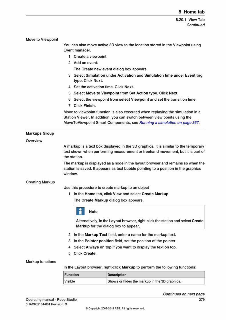
Move to ViewpointYou can also move active 3D view to the location stored in the Viewpoint usingEvent manager.
1 Create a viewpoint.2 Add an event.
The Create new event dialog box appears.3 Select Simulation under Activation and Simulation time under Event trig
type. Click Next.4 Set the activation time. Click Next.5 Select Move to Viewpoint from Set Action type. Click Next.6 Select the viewpoint from select Viewpoint and set the transition time.7 Click Finish.
Move to viewpoint function is also executed when replaying the simulation in aStation Viewer. In addition, you can switch between view points using theMoveToViewpoint Smart Components, see Running a simulation on page 367.
Markups Group
OverviewA markup is a text box displayed in the 3D graphics. It is similar to the temporarytext shown when performing measurement or freehand movement, but it is part ofthe station.The markup is displayed as a node in the layout browser and remains so when thestation is saved. It appears as text bubble pointing to a position in the graphicswindow.
Creating MarkupUse this procedure to create markup to an object
1 In the Home tab, click View and select Create Markup.The Create Markup dialog box appears.
Note
Alternatively, in the Layout browser, right-click the station and selectCreateMarkup for the dialog box to appear.
2 In the Markup Text field, enter a name for the markup text.3 In the Pointer position field, set the position of the pointer.4 Select Always on top if you want to display the text on top.5 Click Create.
Markup functionsIn the Layout browser, right-click Markup to perform the following functions:
DescriptionFunction
Shows or hides the markup in the 3D graphics.Visible
Continues on next pageOperating manual - RobotStudio 2793HAC032104-001 Revision: X
© Copyright 2008-2018 ABB. All rights reserved.
8 Home tab8.20.1 View Tab
Continued

DescriptionFunction
Modifies the Markup properties.Modify Markup
Attaches the markup to another graphical object.Attach to
Detaches the attached markup.Detach
Deletes the markup.Delete
Changes the name of the markup object.Rename
Modify MarkupUse this procedure to modify the markup properties:
1 In the Layout browser, right-click the markup and select Modify Markup.The Modify Markup dialog box appears.
2 Modify the markup text, pointer position or text position.3 Click Apply for the changes to take effect.4 Click Close.
Lights Group
OverviewThe Lights group helps you to control the number and nature of light sources inthe station when advanced lighting is enabled. There are four different kinds oflight sources:
• Ambient Light – Controls the ambient (background) light level in the station.• Infinite Light – A directional light source, similar to the sun, this light source
can cast shadows.• Spotlight – A light source with a cone of influence, this light source can cast
shadows.• Point light – Casts light radially from a specified position, this light source
can not cast shadows.By default, a new station contains two infinite light sources in addition to the ambientlight source. The ambient light source cannot be removed or created, but it can bedisabled. The Create Light menu contains commands for creating a new lightsource and adding it to the station.
Light PropertiesIn the browser, right-click the light source and then select Light Properties fromthe context menu. You can view the Light Properties window. Use this window tomodify the light source. The Light Properties window contains different controlsdepending on the type of light.
DescriptionSettings
Enables or disables the light sourceEnabled (all kinds)
Causes objects influenced by the light to castshadows
Casts shadows (infinite and spot lights)
Controls the color of the lightColor (all kinds)
Controls the ambient (background) intensity ofthe light
Ambient intensity (ambient light)
Continues on next page280 Operating manual - RobotStudio
3HAC032104-001 Revision: X© Copyright 2008-2018 ABB. All rights reserved.
8 Home tab8.20.1 View TabContinued
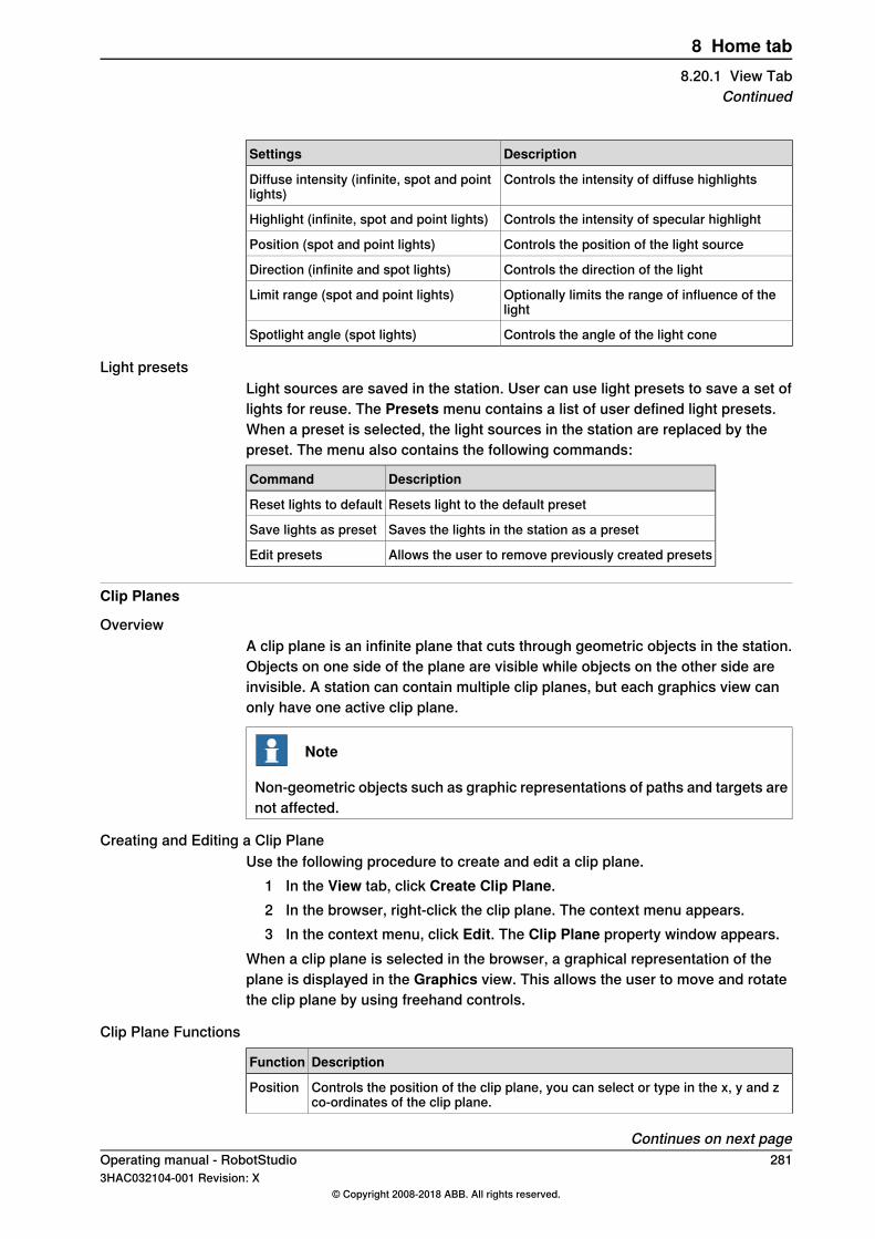
DescriptionSettings
Controls the intensity of diffuse highlightsDiffuse intensity (infinite, spot and pointlights)
Controls the intensity of specular highlightHighlight (infinite, spot and point lights)
Controls the position of the light sourcePosition (spot and point lights)
Controls the direction of the lightDirection (infinite and spot lights)
Optionally limits the range of influence of thelight
Limit range (spot and point lights)
Controls the angle of the light coneSpotlight angle (spot lights)
Light presetsLight sources are saved in the station. User can use light presets to save a set oflights for reuse. The Presets menu contains a list of user defined light presets.When a preset is selected, the light sources in the station are replaced by thepreset. The menu also contains the following commands:
DescriptionCommand
Resets light to the default presetReset lights to default
Saves the lights in the station as a presetSave lights as preset
Allows the user to remove previously created presetsEdit presets
Clip Planes
OverviewA clip plane is an infinite plane that cuts through geometric objects in the station.Objects on one side of the plane are visible while objects on the other side areinvisible. A station can contain multiple clip planes, but each graphics view canonly have one active clip plane.
Note
Non-geometric objects such as graphic representations of paths and targets arenot affected.
Creating and Editing a Clip PlaneUse the following procedure to create and edit a clip plane.
1 In the View tab, click Create Clip Plane.2 In the browser, right-click the clip plane. The context menu appears.3 In the context menu, click Edit. The Clip Plane property window appears.
When a clip plane is selected in the browser, a graphical representation of theplane is displayed in the Graphics view. This allows the user to move and rotatethe clip plane by using freehand controls.
Clip Plane Functions
DescriptionFunction
Controls the position of the clip plane, you can select or type in the x, y and zco-ordinates of the clip plane.
Position
Continues on next pageOperating manual - RobotStudio 2813HAC032104-001 Revision: X
© Copyright 2008-2018 ABB. All rights reserved.
8 Home tab8.20.1 View Tab
Continued
DescriptionFunction
Controls the orientation of the clip plane, you can select or type in the x, y andz co-ordinates of the clip plane.
Normal
Allows the user to reverse the orientation of the clip plane.Flip
Enables or disables the clip plane in the active graphics view.Active
FreehandFreehand options are used to move and rotate the selected object. User can selectthe coordinate system.
Moving an item1 In the Layout browser, select the item you want to move.2 Click Move.3 In the graphics window, click one of the axes and drag the item into position.
Rotating an item1 In the Layout browser, select the item you want to rotate.2 Click Rotate.3 In the graphics window, click one of the rotational rings and drag the item
into position.If you press the ALT key while rotating, the item will snap 10 degrees at atime.
WorldUse this option to move or rotate an object in the station in relation with the specifiedcoordinate system. The following options are available:
• World• Local• UCS• Active Workobject• Active Tool
Close GraphicsSelect this option to close the Graphics Tools tabs.
282 Operating manual - RobotStudio3HAC032104-001 Revision: X
© Copyright 2008-2018 ABB. All rights reserved.
8 Home tab8.20.1 View TabContinued
8.20.2 Edit Tab
OverviewThe Edit tab contains commands for working with materials and their applicationon geometric objects. The available options are:
• Materials• Pick Material• Apply Material• Replace Material• Edit Materials• Adjust Textures• Invert Surfaces• Close Graphics
Appearance GroupThe Appearance group contains the following options:
DescriptionSettings
Contains a gallery of predefined and user defined materialsMaterials
Allows the user to select a materialPick Material
Activates or deactivates apply material modeApply Material
Allows the user to replace material in a part that contains several differentmaterials.
Replace Material
Allows editing of user defined materialsEdit Materials
Allows the user to adjust texture coordinates on surfaces directly in themain graphics view
Adjust Textures
Allows the user to invert the surfaces when selected in the Grahics win-dow. The back side of the surface is highlighted in red.
Invert Surfaces
To close the Graphics tools tab.Close Graphics
MaterialsTheMaterialmenu contains controls for setting material parameters or for selectinga material from the list of user defined and predefined materials. It is also possibleto save the current material to the user defined materials list.
Apply MaterialWhen Apply Material is activated, the active material is automatically applied tothe geometric surfaces or objects (depending on selection mode) selected in theGraphics view. The active material is selected by using the Materials menu or thePick Material command. When a material is selected, Apply Material is automaticallyactivated.
Replace MaterialThe Replace Material menu allows you to replace material in a part that consistsof different materials. Select a material from the Materials gallery and click on thesurface of the part to replace its material.
Continues on next pageOperating manual - RobotStudio 2833HAC032104-001 Revision: X
© Copyright 2008-2018 ABB. All rights reserved.
8 Home tab8.20.2 Edit Tab

Edit MaterialsThe Edit Materials menu allows editing of user defined materials. Click this buttonto see the list of defined materials. This list can be edited by adding, deleting andcopying materials. The name and description of a material can be changed byright-clicking in the list. A preview of the selected material is displayed in theGraphics view.
Adjust TexturesTheAdjust Texturesmenu allows the user to adjust texture coordinates on surfacesdirectly in the main Graphics view. When the command is activated and a texturedsurface is selected, the user can use the keyboard to move, rotate, mirror and scalethe texture on the surface.
Graphics browserA separate browser window is displayed when one of the graphics menu is selected.It contains objects in the station that are related to the graphics system. Thefollowing options are available:
• Markups• Viewpoints• Lights• Clip planes
Close GraphicsSelect this option to close the Graphics Tools tabs .
284 Operating manual - RobotStudio3HAC032104-001 Revision: X
© Copyright 2008-2018 ABB. All rights reserved.
8 Home tab8.20.2 Edit TabContinued
9 Modeling tab9.1 Overview
The Modeling tabThe Modeling tab contains the controls for creating and grouping components,creating bodies, measurements and CAD operations.
Operating manual - RobotStudio 2853HAC032104-001 Revision: X
© Copyright 2008-2018 ABB. All rights reserved.
9 Modeling tab9.1 Overview
9.2 Component Group
Creating a component group1 Click Component Group. The Group node will be displayed in the Layout
browser.2 Click the objects to add to the group. Drag them to the Group node.
286 Operating manual - RobotStudio3HAC032104-001 Revision: X
© Copyright 2008-2018 ABB. All rights reserved.
9 Modeling tab9.2 Component Group

9.3 Empty Part
Creating an empty part1 Click Empty Part. The Part node will be displayed in the Layout browser.
Operating manual - RobotStudio 2873HAC032104-001 Revision: X
© Copyright 2008-2018 ABB. All rights reserved.
9 Modeling tab9.3 Empty Part
9.4 Smart Component
9.4.1 Smart Component
OverviewSmart Component is a RobotStudio object (with or without a 3D graphicalrepresentation) that has the behavior which can be implemented by code-behindand/or aggregation of other Smart Components.
TerminologyThe following table describes the different terminologies that you come acrosswhen working with Smart Component.
DefinitionTerm
A .NET class associated with a Smart Component that canimplement custom behavior by reacting to certain events, forexample simulation time steps and changes in property values.
Code behind
An object attached to a Smart Component that has value, typeand certain other characteristics. The property value is usedby code behind to control the behavior of the Smart Component.
[Dynamic] property
Connects the value of one property to the value of anotherproperty.
[Property] binding
Key-value pairs that contain additional information about adynamic property, for example value constraints.
[Property] attributes
An object attached to a Smart Component that has a value anda direction (input/output), analogous to I/O signals on a robotcontroller. The signal value is used by code behind to controlthe behavior of the Smart Component.
[I/O] signal
Connects the value of one signal to the value of a differentsignal.
[I/O] connection
The process of connecting several Smart Components usingbindings and/or connections in order to implement a morecomplex behavior.
Aggregation
Data object contained in a Smart Component. Uses includecode behind assembly and localized resources.
Asset
288 Operating manual - RobotStudio3HAC032104-001 Revision: X
© Copyright 2008-2018 ABB. All rights reserved.
9 Modeling tab9.4.1 Smart Component
9.4.2 Smart Component Editor
OverviewThe Smart Component Editor allows you to create, edit, and aggregate SmartComponents using a graphical user interface. It is an alternative to using the xmlbased library compiler.
Layout of a Smart Component EditorIt consists of an icon, the name, the description for the component wherein thedescription can be modified by typing in the text box, and a combo box.The combo box specifies the language for editing localized strings (captions anddescriptions) in the component. The default language is always English, even ifthe application language is different. For more information, seeAssets on page291.The Smart Component Editor consists of the following tabs:
• The Compose tab on page 290• The Properties and Bindings tab on page 293• The Signals and Connections tab on page 296• The Design tab on page 299
Opening a Smart Component EditorClick Smart Component or select Edit Component from the context menu.The Smart Component Editor window appears.
Protecting a Smart Component from editsYou can protect a Smart Component from being edited. To protect the smartcomponent, right-click the smart component, and then click Protected. You canalso optionally specify a password that will be required to unlock the componentfor edits.Protecting a Smart Component hides its internal structure and protects it fromedits. You can use this feature to hide the complexity in the smart component, andto secure the functionality. Child components in a protected smart component arehidden in all RobotStudio browsers and also in the Signal Analyzer browser.
Note
Protecting a Smart Component in this manner is a way of hiding complexity, andis not for providing security or securely protecting it.
Operating manual - RobotStudio 2893HAC032104-001 Revision: X
© Copyright 2008-2018 ABB. All rights reserved.
9 Modeling tab9.4.2 Smart Component Editor
9.4.3 The Compose tab
OverviewThe Compose tab consists of the following:
• Child components on page 290• Saved States on page 291• Assets on page 291
Child componentsIt is a list box that displays all the objects contained by the component. Objectsconnected to a library have an overlay that indicates that the objects are locked.Smart Components are displayed first followed by other type of objects.If an object is selected from the list, the following commands are displayed in theright panel:
DescriptionCommand
Adds a child object to the component from the list.Add componentYou can select a built-in base Smart Component, a new emptySmart Component, a library from file or a geometric part fromfile.Base components are organized as sub-menus based on theusage. For example, Signals and Properties, Sensors, Actionsand so on. Recently used base components are listed at thetop.For more information about base Smart Component, see BasicSmart Components on page 300.
Sets the context of the Editor to the parent of the componentthat is currently being edited. If the parent is the station, seeStation Logic on page 365.
Edit parent
Disconnects the selected object from library, allowing it to beedited.
Disconnect from library
Opens a dialog box where you can export and save the com-ponent definition along with its properties as an *.rsxml file
Export to XML
Right-click on the selected object to display the following context menu items
DescriptionItem
Sets the context of the Editor to the selected child object.Edit
Deletes the child object.Delete
Indicates if the object should be displayed in the Layoutbrowser.
Show in Browser
Sets the object as the Role of the component. The SmartComponent will inherit certain characteristics of the Role object.For example, attaching a component with a tool as Role to arobot will cause a ToolData to be created.
Set as Role
Opens the Property editor dialog box for the object. See Prop-erty Editor on page 318.
Properties
Continues on next page290 Operating manual - RobotStudio
3HAC032104-001 Revision: X© Copyright 2008-2018 ABB. All rights reserved.
9 Modeling tab9.4.3 The Compose tab
Saved StatesThe state of the component can be saved to be restored later. The state containsselected modifiable aspects of the component and its child components at the timewhen the state was saved. The following commands are available:
DescriptionCommand
Opens the Save Current State dialog box. See Save CurrentState on page 291.
Save Current State
Restores the component to the selected state.Restore Selected State
Opens a window that displays detailed information about theselected state.
Details
Deletes the selected state.Delete
Save Current State1 In the Name text box, enter a name for the state. If a state with the same
name already exists, you will be asked to overwrite the existing state.2 In the Description text box, enter the description for the state.3 In the Values to save, select the value to be saved.4 Select the check box to save the state of all child components.
Note
When working on a station level,• In the Values to save, you can also select certain Virtual Controller
values in the saved states.• You need not select the option Recursive as the state of the station
is always saved.For more information, see Station Logic on page 365.
AssetsThe assets contained in the component are displayed as grid.The following commands are available:
DescriptionCommand
Opens a dialog box and allows you to browse and select anyfile as an asset.
Add Asset
Opens a dialog box and allows you to browse and select animage that represents a Smart Component.
Set Icon
Replaces the data of all the assets with the data of the corres-ponding file on the disk. If the file is not available, a warningmessage is displayed in the output window.
Update All Assets
Opens the selected asset in the associated programView
Opens a dialog box and allows you to save the selected asset.Save
Deletes the selected asset.Delete
Continues on next pageOperating manual - RobotStudio 2913HAC032104-001 Revision: X
© Copyright 2008-2018 ABB. All rights reserved.
9 Modeling tab9.4.3 The Compose tab
Continued
Note
The text resources (descriptions) for properties and signals are stored in an assetcalledResources.<language-id>.xml. If this is deleted, the texts for that languagewill be empty and the default (English) will be used. The default language whenauthoring a component is always English, regardless of the application language.
292 Operating manual - RobotStudio3HAC032104-001 Revision: X
© Copyright 2008-2018 ABB. All rights reserved.
9 Modeling tab9.4.3 The Compose tabContinued

9.4.4 The Properties and Bindings tab
OverviewThe Properties and Bindings tab consists of the following:
• Dynamic Properties on page 293• Property Bindings on page 294
Dynamic PropertiesThe dynamic properties contained in the component are displayed in a grid.The following commands are available
DescriptionCommand
Opens the Add Dynamic Property dialog box. See Add or EditDynamic Property on page 293.
Add Dynamic Property
Opens the Expose Child Property dialog box. See Expose ChildProperty on page 294.
Expose Child Property
Opens the Edit Dynamic Property dialog box for the selectedproperty.
Edit
Deletes the selected property.Delete
Add or Edit Dynamic PropertyThe Add Dynamic Property dialog box allows you to create a new dynamic propertyor edit an existing property.The following controls are available:
DescriptionControl
Specifies an identifier for the property. The identifier must bealphanumeric, start with a letter and must be unique.
Property Identifier
Detailed description of the property.Description
Indicates if the property value should be possible to modify inGUI such as the Property Editor.
Read-only
Specifies the type of the property from a list of allowed types.Property Type
Specifies the value of the property. The control is updated whenyou change the property type and/or attributes.
Property Value
Allows you to add, remove, and modify property attributes.AttributesThe following lists the available attributes:
• MinValue• MaxValue• Quantity• Slider• AutoApply
Numeric attributes are specified in SI units.
Note
When editing an existing property, the Identifier and Type controls are lockedand cannot be modified. If the input is valid the OK button is enabled, allowingyou to add or update the property. If not, an error icon is displayed.
Continues on next pageOperating manual - RobotStudio 2933HAC032104-001 Revision: X
© Copyright 2008-2018 ABB. All rights reserved.
9 Modeling tab9.4.4 The Properties and Bindings tab
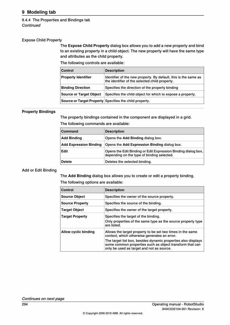
Expose Child PropertyThe Expose Child Property dialog box allows you to add a new property and bindto an existing property in a child object. The new property will have the same typeand attributes as the child property.The following controls are available:
DescriptionControl
Identifier of the new property. By default, this is the same asthe identifier of the selected child property.
Property Identifier
Specifies the direction of the property bindingBinding Direction
Specifies the child object for which to expose a property.Source or Target Object
Specifies the child property.Source or Target Property
Property BindingsThe property bindings contained in the component are displayed in a grid.The following commands are available:
DescriptionCommand
Opens the Add Binding dialog box.Add Binding
Opens the Add Expression Binding dialog box.Add Expression Binding
Opens the Edit Binding or Edit Expression Binding dialog box,depending on the type of binding selected.
Edit
Deletes the selected binding.Delete
Add or Edit BindingThe Add Binding dialog box allows you to create or edit a property binding.The following options are available:
DescriptionControl
Specifies the owner of the source property.Source Object
Specifies the source of the binding.Source Property
Specifies the owner of the target property.Target Object
Specifies the target of the binding.Target PropertyOnly properties of the same type as the source property typeare listed.
Allows the target property to be set two times in the samecontext, which otherwise generates an error.
Allow cyclic binding
The target list box, besides dynamic properties also displayssome common properties such as object transform that canonly be used as target and not as source.
Continues on next page294 Operating manual - RobotStudio
3HAC032104-001 Revision: X© Copyright 2008-2018 ABB. All rights reserved.
9 Modeling tab9.4.4 The Properties and Bindings tabContinued
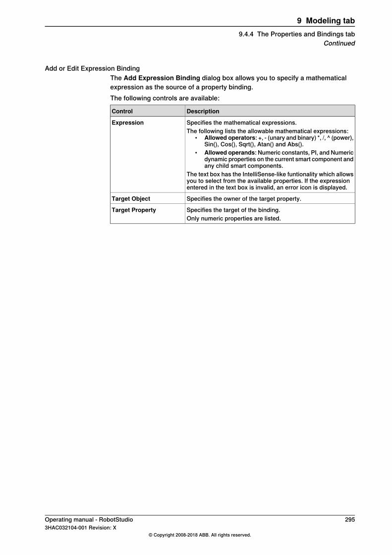
Add or Edit Expression BindingThe Add Expression Binding dialog box allows you to specify a mathematicalexpression as the source of a property binding.The following controls are available:
DescriptionControl
Specifies the mathematical expressions.ExpressionThe following lists the allowable mathematical expressions:
• Allowed operators: +, - (unary and binary) *, /, ^ (power),Sin(), Cos(), Sqrt(), Atan() and Abs().
• Allowed operands: Numeric constants, PI, and Numericdynamic properties on the current smart component andany child smart components.
The text box has the IntelliSense-like funtionality which allowsyou to select from the available properties. If the expressionentered in the text box is invalid, an error icon is displayed.
Specifies the owner of the target property.Target Object
Specifies the target of the binding.Target PropertyOnly numeric properties are listed.
Operating manual - RobotStudio 2953HAC032104-001 Revision: X
© Copyright 2008-2018 ABB. All rights reserved.
9 Modeling tab9.4.4 The Properties and Bindings tab
Continued
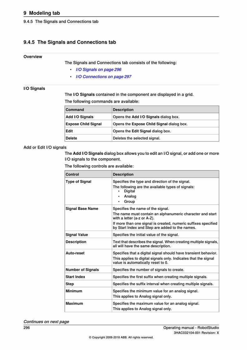
9.4.5 The Signals and Connections tab
OverviewThe Signals and Connections tab consists of the following:
• I/O Signals on page 296• I/O Connections on page 297
I/O SignalsThe I/O Signals contained in the component are displayed in a grid.The following commands are available:
DescriptionCommand
Opens the Add I/O Signals dialog box.Add I/O Signals
Opens the Expose Child Signal dialog box.Expose Child Signal
Opens the Edit Signal dialog box.Edit
Deletes the selected signal.Delete
Add or Edit I/O signalsTheAdd I/O Signals dialog box allows you to edit an I/O signal, or add one or moreI/O signals to the component.The following controls are available:
DescriptionControl
Specifies the type and direction of the signal.Type of SignalThe following are the available types of signals:
• Digital• Analog• Group
Specifies the name of the signal.Signal Base NameThe name must contain an alphanumeric character and startwith a letter (a-z or A-Z).If more than one signal is created, numeric suffixes specifiedby Start Index and Step are added to the names.
Specifies the initial value of the signal.Signal Value
Text that describes the signal. When creating multiple signals,all will have the same description.
Description
Specifies that a digital signal should have transient behavior.Auto-resetThis applies to digital signals only. Indicates that the signalvalue is automatically reset to 0.
Specifies the number of signals to create.Number of Signals
Specifies the first suffix when creating multiple signals.Start Index
Specifies the suffix interval when creating multiple signals.Step
Specifies the minimum value for an analog signal.MinimumThis applies to Analog signal only.
Specifies the maximum value for an analog signal.MaximumThis applies to Analog signal only.
Continues on next page296 Operating manual - RobotStudio
3HAC032104-001 Revision: X© Copyright 2008-2018 ABB. All rights reserved.
9 Modeling tab9.4.5 The Signals and Connections tab
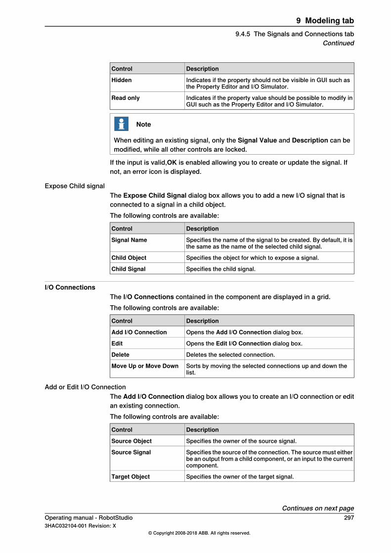
DescriptionControl
Indicates if the property should not be visible in GUI such asthe Property Editor and I/O Simulator.
Hidden
Indicates if the property value should be possible to modify inGUI such as the Property Editor and I/O Simulator.
Read only
Note
When editing an existing signal, only the Signal Value and Description can bemodified, while all other controls are locked.
If the input is valid,OK is enabled allowing you to create or update the signal. Ifnot, an error icon is displayed.
Expose Child signalThe Expose Child Signal dialog box allows you to add a new I/O signal that isconnected to a signal in a child object.The following controls are available:
DescriptionControl
Specifies the name of the signal to be created. By default, it isthe same as the name of the selected child signal.
Signal Name
Specifies the object for which to expose a signal.Child Object
Specifies the child signal.Child Signal
I/O ConnectionsThe I/O Connections contained in the component are displayed in a grid.The following controls are available:
DescriptionControl
Opens the Add I/O Connection dialog box.Add I/O Connection
Opens the Edit I/O Connection dialog box.Edit
Deletes the selected connection.Delete
Sorts by moving the selected connections up and down thelist.
Move Up or Move Down
Add or Edit I/O ConnectionThe Add I/O Connection dialog box allows you to create an I/O connection or editan existing connection.The following controls are available:
DescriptionControl
Specifies the owner of the source signal.Source Object
Specifies the source of the connection. The source must eitherbe an output from a child component, or an input to the currentcomponent.
Source Signal
Specifies the owner of the target signal.Target Object
Continues on next pageOperating manual - RobotStudio 2973HAC032104-001 Revision: X
© Copyright 2008-2018 ABB. All rights reserved.
9 Modeling tab9.4.5 The Signals and Connections tab
Continued
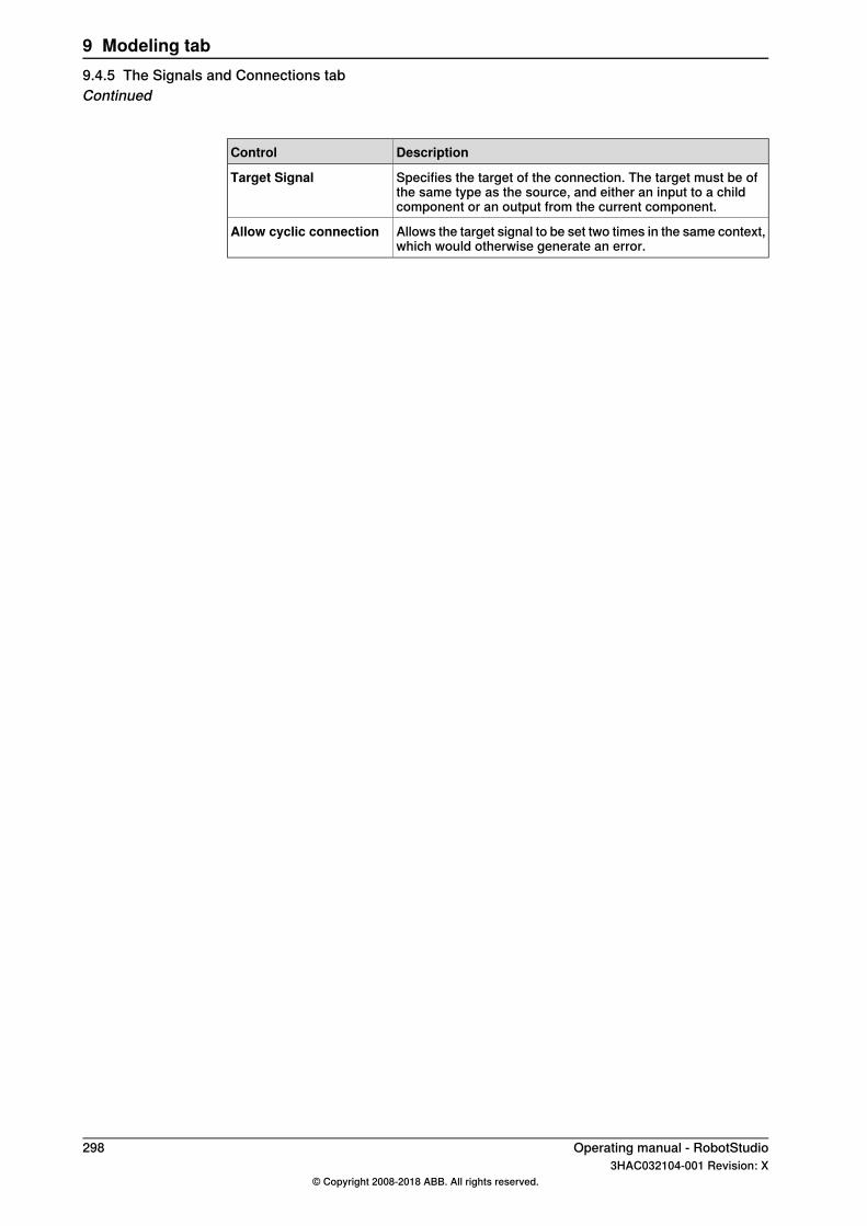
DescriptionControl
Specifies the target of the connection. The target must be ofthe same type as the source, and either an input to a childcomponent or an output from the current component.
Target Signal
Allows the target signal to be set two times in the same context,which would otherwise generate an error.
Allow cyclic connection
298 Operating manual - RobotStudio3HAC032104-001 Revision: X
© Copyright 2008-2018 ABB. All rights reserved.
9 Modeling tab9.4.5 The Signals and Connections tabContinued
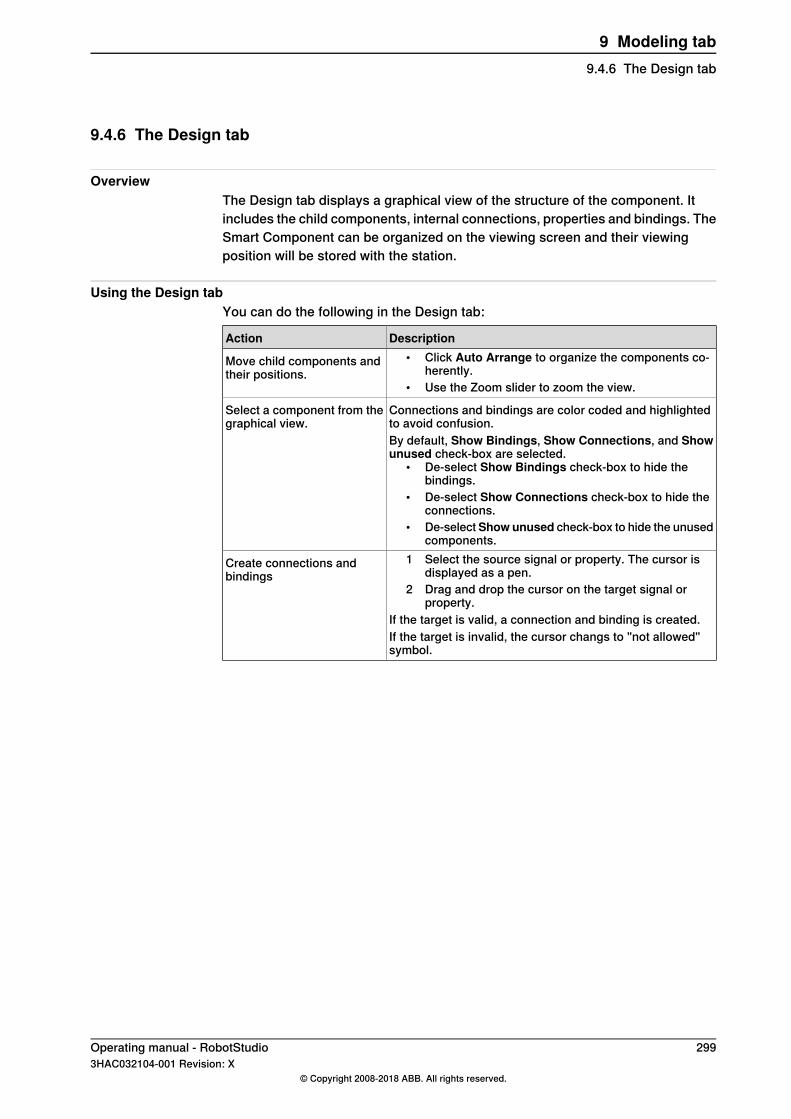
9.4.6 The Design tab
OverviewThe Design tab displays a graphical view of the structure of the component. Itincludes the child components, internal connections, properties and bindings. TheSmart Component can be organized on the viewing screen and their viewingposition will be stored with the station.
Using the Design tabYou can do the following in the Design tab:
DescriptionAction• Click Auto Arrange to organize the components co-
herently.• Use the Zoom slider to zoom the view.
Move child components andtheir positions.
Connections and bindings are color coded and highlightedto avoid confusion.
Select a component from thegraphical view.
By default, Show Bindings, Show Connections, and Showunused check-box are selected.
• De-select Show Bindings check-box to hide thebindings.
• De-select Show Connections check-box to hide theconnections.
• De-selectShowunused check-box to hide the unusedcomponents.
1 Select the source signal or property. The cursor isdisplayed as a pen.
2 Drag and drop the cursor on the target signal orproperty.
If the target is valid, a connection and binding is created.
Create connections andbindings
If the target is invalid, the cursor changs to "not allowed"symbol.
Operating manual - RobotStudio 2993HAC032104-001 Revision: X
© Copyright 2008-2018 ABB. All rights reserved.
9 Modeling tab9.4.6 The Design tab
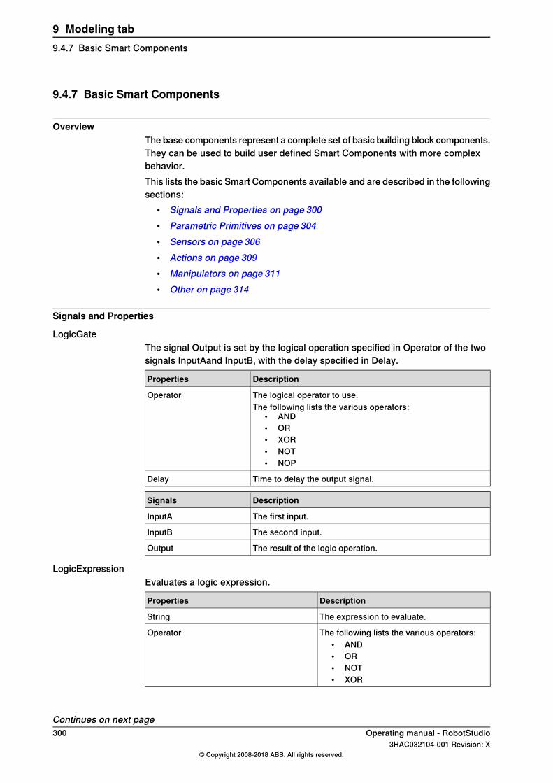
9.4.7 Basic Smart Components
OverviewThe base components represent a complete set of basic building block components.They can be used to build user defined Smart Components with more complexbehavior.This lists the basic Smart Components available and are described in the followingsections:
• Signals and Properties on page 300• Parametric Primitives on page 304• Sensors on page 306• Actions on page 309• Manipulators on page 311• Other on page 314
Signals and Properties
LogicGateThe signal Output is set by the logical operation specified in Operator of the twosignals InputAand InputB, with the delay specified in Delay.
DescriptionProperties
The logical operator to use.OperatorThe following lists the various operators:
• AND• OR• XOR• NOT• NOP
Time to delay the output signal.Delay
DescriptionSignals
The first input.InputA
The second input.InputB
The result of the logic operation.Output
LogicExpressionEvaluates a logic expression.
DescriptionProperties
The expression to evaluate.String
The following lists the various operators:• AND• OR• NOT• XOR
Operator
Continues on next page300 Operating manual - RobotStudio
3HAC032104-001 Revision: X© Copyright 2008-2018 ABB. All rights reserved.
9 Modeling tab9.4.7 Basic Smart Components

DescriptionSignals
Contains the result of the evaluation.Result
LogicMuxOutput is set according to: Output = (Input A * NOT Selector) + (Input B * Selector)
DescriptionSignals
When low, the first input is selected.SelectorWhen high, the second input is selected.
Specifies the first input.InputA
Specifies the second input.InputB
Specifies the result of the operation.Output
LogicSplitThe LogicSplit takes Input and sets OutputHigh to the same as Input, and OutputLowas the inverse of Input.PulseHigh sends a pulse when Input is set to high, and PulseLow sends a pulsewhen Input is set to low.
DescriptionSignals
Specifies the input signal.Input
Goes high (1) when input is 1.OutputHigh
Goes high (1) when input is 0.OutputLow
Sends pulse when input is set to high.PulseHigh
Sends pulse when input is set to low.PulseLow
LogicSRLatchTheLogicSRLatch has one stable state.
• When Set=1, Output=1 and InvOutput=0• When Reset=1, Output=0 and InvOutput=1
DescriptionSignals
Sets the output signal.Set
Resets the output signal.Reset
Specifies output signal.Output
Specifies Inverse output signal.InvOutput
ConverterConverts between property values and signal values.
DescriptionProperties
Converts to AnalogOutput.AnalogProperty
Converts to DigitalOutput.DigitalProperty
Converts to GroupOutput.GroupProperty
Converts from DigitalInput and to DigitalOutput.BooleanProperty
Continues on next pageOperating manual - RobotStudio 3013HAC032104-001 Revision: X
© Copyright 2008-2018 ABB. All rights reserved.
9 Modeling tab9.4.7 Basic Smart Components
Continued

DescriptionSignals
Converts to DigitalProperty.DigitalInput
Converted from DigitalProperty.DigitalOutput
Converts to AnalogProperty.AnalogInput
Converted from AnalogProperty.AnalogOutput
Converts to GroupProperty.GroupInput
Converted from GroupProperty.GroupOutput
VectorConverterConverts between Vector3 and X, Y,and Z values.
DescriptionProperties
Specifies the X-value of Vector.X
Specifies the Y-value of Vector.Y
Specifies the Z-value of VectorZ
Specifies the vector value..Vector
ExpressionThe Expression consists of numeric literals (including PI), parentheses,mathematical operators +,-,*,/,^ (power) and mathematical functions sin, cos, sqrt,atan, abs. Any other strings are interpreted as variables, which are added asadditional properties. The result is displayed in Result.
DescriptionSignals
Specifies the expression to evaluate.Expression
Specifies the result of evaluation.Result
Specifies automatically generated variables.NNN
ComparerThe Comparer compares First value with Second value, using Operator. Output isset to 1 if the condition is met.
DescriptionProperties
Specifies the first value.ValueA
Specifies the second value.ValueB
Specifies the comparison operator.OperatorThe following lists the various operators:
• ==• !=• >• >=• <• <=
DescriptionSignals
True if the comparison evaluates to true, otherwise false.Output
Continues on next page302 Operating manual - RobotStudio
3HAC032104-001 Revision: X© Copyright 2008-2018 ABB. All rights reserved.
9 Modeling tab9.4.7 Basic Smart ComponentsContinued
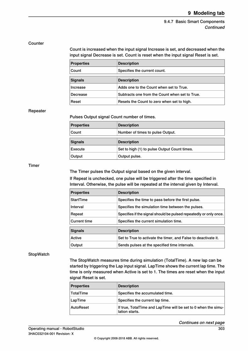
CounterCount is increased when the input signal Increase is set, and decreased when theinput signal Decrease is set. Count is reset when the input signal Reset is set.
DescriptionProperties
Specifies the current count.Count
DescriptionSignals
Adds one to the Count when set to True.Increase
Subtracts one from the Count when set to True.Decrease
Resets the Count to zero when set to high.Reset
RepeaterPulses Output signal Count number of times.
DescriptionProperties
Number of times to pulse Output.Count
DescriptionSignals
Set to high (1) to pulse Output Count times.Execute
Output pulse.Output
TimerThe Timer pulses the Output signal based on the given interval.If Repeat is unchecked, one pulse will be triggered after the time specified inInterval. Otherwise, the pulse will be repeated at the interval given by Interval.
DescriptionProperties
Specifies the time to pass before the first pulse.StartTime
Specifies the simulation time between the pulses.Interval
Specifies if the signal should be pulsed repeatedly or only once.Repeat
Specifies the current simulation time.Current time
DescriptionSignals
Set to True to activate the timer, and False to deactivate it.Active
Sends pulses at the specified time intervals.Output
StopWatchThe StopWatch measures time during simulation (TotalTime). A new lap can bestarted by triggering the Lap input signal. LapTime shows the current lap time. Thetime is only measured when Active is set to 1. The times are reset when the inputsignal Reset is set.
DescriptionProperties
Specifies the accumulated time.TotalTime
Specifies the current lap time.LapTime
If true, TotalTime and LapTime will be set to 0 when the simu-lation starts.
AutoReset
Continues on next pageOperating manual - RobotStudio 3033HAC032104-001 Revision: X
© Copyright 2008-2018 ABB. All rights reserved.
9 Modeling tab9.4.7 Basic Smart Components
Continued
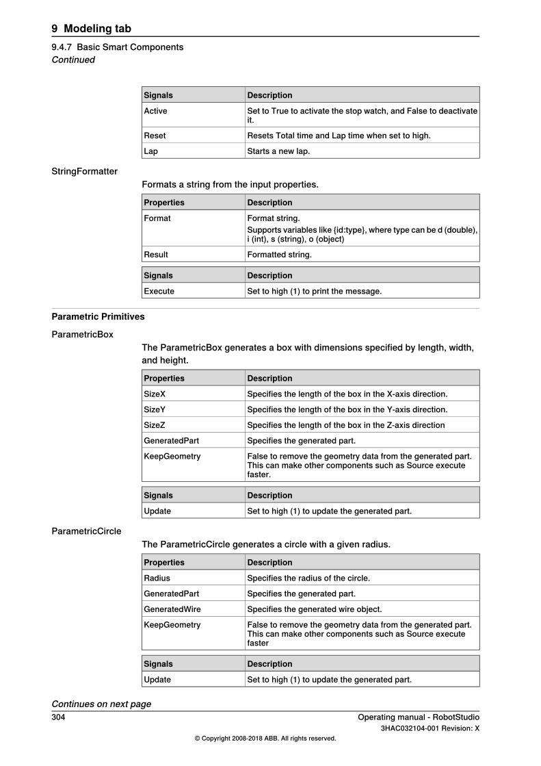
DescriptionSignals
Set to True to activate the stop watch, and False to deactivateit.
Active
Resets Total time and Lap time when set to high.Reset
Starts a new lap.Lap
StringFormatterFormats a string from the input properties.
DescriptionProperties
Format string.FormatSupports variables like {id:type}, where type can be d (double),i (int), s (string), o (object)
Formatted string.Result
DescriptionSignals
Set to high (1) to print the message.Execute
Parametric Primitives
ParametricBoxThe ParametricBox generates a box with dimensions specified by length, width,and height.
DescriptionProperties
Specifies the length of the box in the X-axis direction.SizeX
Specifies the length of the box in the Y-axis direction.SizeY
Specifies the length of the box in the Z-axis directionSizeZ
Specifies the generated part.GeneratedPart
False to remove the geometry data from the generated part.This can make other components such as Source executefaster.
KeepGeometry
DescriptionSignals
Set to high (1) to update the generated part.Update
ParametricCircleThe ParametricCircle generates a circle with a given radius.
DescriptionProperties
Specifies the radius of the circle.Radius
Specifies the generated part.GeneratedPart
Specifies the generated wire object.GeneratedWire
False to remove the geometry data from the generated part.This can make other components such as Source executefaster
KeepGeometry
DescriptionSignals
Set to high (1) to update the generated part.Update
Continues on next page304 Operating manual - RobotStudio
3HAC032104-001 Revision: X© Copyright 2008-2018 ABB. All rights reserved.
9 Modeling tab9.4.7 Basic Smart ComponentsContinued
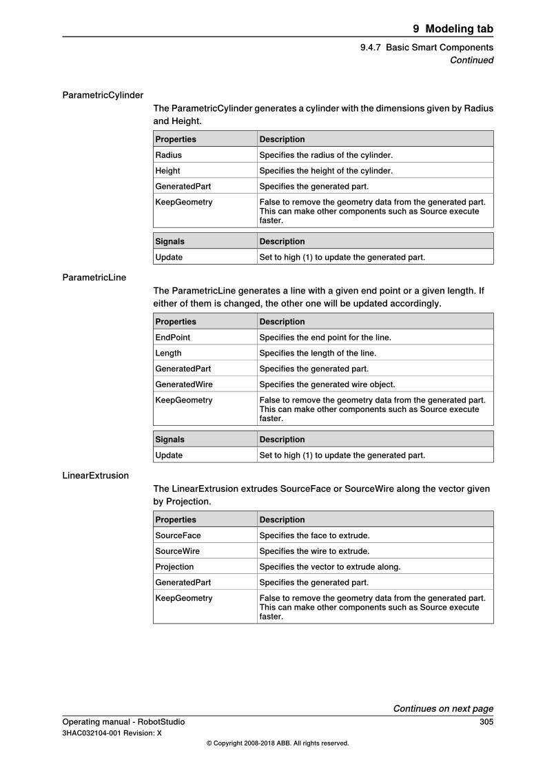
ParametricCylinderThe ParametricCylinder generates a cylinder with the dimensions given by Radiusand Height.
DescriptionProperties
Specifies the radius of the cylinder.Radius
Specifies the height of the cylinder.Height
Specifies the generated part.GeneratedPart
False to remove the geometry data from the generated part.This can make other components such as Source executefaster.
KeepGeometry
DescriptionSignals
Set to high (1) to update the generated part.Update
ParametricLineThe ParametricLine generates a line with a given end point or a given length. Ifeither of them is changed, the other one will be updated accordingly.
DescriptionProperties
Specifies the end point for the line.EndPoint
Specifies the length of the line.Length
Specifies the generated part.GeneratedPart
Specifies the generated wire object.GeneratedWire
False to remove the geometry data from the generated part.This can make other components such as Source executefaster.
KeepGeometry
DescriptionSignals
Set to high (1) to update the generated part.Update
LinearExtrusionThe LinearExtrusion extrudes SourceFace or SourceWire along the vector givenby Projection.
DescriptionProperties
Specifies the face to extrude.SourceFace
Specifies the wire to extrude.SourceWire
Specifies the vector to extrude along.Projection
Specifies the generated part.GeneratedPart
False to remove the geometry data from the generated part.This can make other components such as Source executefaster.
KeepGeometry
Continues on next pageOperating manual - RobotStudio 3053HAC032104-001 Revision: X
© Copyright 2008-2018 ABB. All rights reserved.
9 Modeling tab9.4.7 Basic Smart Components
Continued
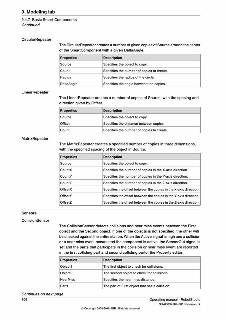
CircularRepeaterThe CircularRepeater creates a number of given copies of Source around the centerof the SmartComponent with a given DeltaAngle.
DescriptionProperties
Specifies the object to copy.Source
Specifies the number of copies to create.Count
Specifies the radius of the circle.Radius
Specifies the angle between the copies.DeltaAngle
LinearRepeaterThe LinearRepeater creates a number of copies of Source, with the spacing anddirection given by Offset.
DescriptionProperties
Specifies the object to copy.Source
Specifies the distance between copies.Offset
Specifies the number of copies to create.Count
MatrixRepeaterThe MatrixRepeater creates a specified number of copies in three dimensions,with the specified spacing of the object in Source.
DescriptionProperties
Specifies the object to copy.Source
Specifies the number of copies in the X-axis direction.CountX
Specifies the number of copies in the Y-axis direction.CountY
Specifies the number of copies in the Z-axis direction.CountZ
Specifies the offset between the copies in the X-axis direction.OffsetX
Specifies the offset between the copies in the Y-axis direction.OffsetY
Specifies the offset between the copies in the Z-axis direction.OffsetZ
Sensors
CollisionSensorThe CollisionSensor detects collisions and near miss events between the Firstobject and the Second object. If one of the objects is not specified, the other willbe checked against the entire station. When the Active signal is high and a collisionor a near miss event occurs and the component is active, the SensorOut signal isset and the parts that participate in the collision or near miss event are reportedin the first colliding part and second colliding partof the Property editor.
DescriptionProperties
The first object to check for collisions.Object1
The second object to check for collisions.Object2
Specifies the near miss distance.NearMiss
The part of First object that has a collision.Part1
Continues on next page306 Operating manual - RobotStudio
3HAC032104-001 Revision: X© Copyright 2008-2018 ABB. All rights reserved.
9 Modeling tab9.4.7 Basic Smart ComponentsContinued
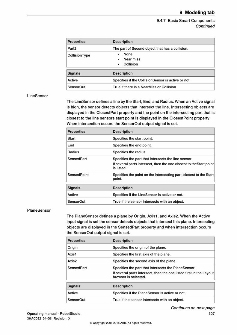
DescriptionProperties
The part of Second object that has a collision.Part2• None• Near miss• Collision
CollisionType
DescriptionSignals
Specifies if the CollisionSensor is active or not.Active
True if there is a NearMiss or Collision.SensorOut
LineSensorThe LineSensor defines a line by the Start, End, and Radius. When an Active signalis high, the sensor detects objects that intersect the line. Intersecting objects aredisplayed in the ClosestPart property and the point on the intersecting part that isclosest to the line sensors start point is displayed in the ClosestPoint property.When intersection occurs the SensorOut output signal is set.
DescriptionProperties
Specifies the start point.Start
Specifies the end point.End
Specifies the radius.Radius
Specifies the part that intersects the line sensor.SensedPartIf several parts intersect, then the one closest to theStart pointis listed.
Specifies the point on the intersecting part, closest to the Startpoint.
SensedPoint
DescriptionSignals
Specifies if the LineSensor is active or not.Active
True if the sensor intersects with an object.SensorOut
PlaneSensorThe PlaneSensor defines a plane by Origin, Axis1, and Axis2. When the Activeinput signal is set the sensor detects objects that intersect this plane. Intersectingobjects are displayed in the SensedPart property and when intersection occursthe SensorOut output signal is set.
DescriptionProperties
Specifies the origin of the plane.Origin
Specifies the first axis of the plane.Axis1
Specifies the second axis of the plane.Axis2
Specifies the part that intersects the PlaneSensor.SensedPartIf several parts intersect, then the one listed first in the Layoutbrowser is selected.
DescriptionSignals
Specifies if the PlaneSensor is active or not.Active
True if the sensor intersects with an object.SensorOut
Continues on next pageOperating manual - RobotStudio 3073HAC032104-001 Revision: X
© Copyright 2008-2018 ABB. All rights reserved.
9 Modeling tab9.4.7 Basic Smart Components
Continued
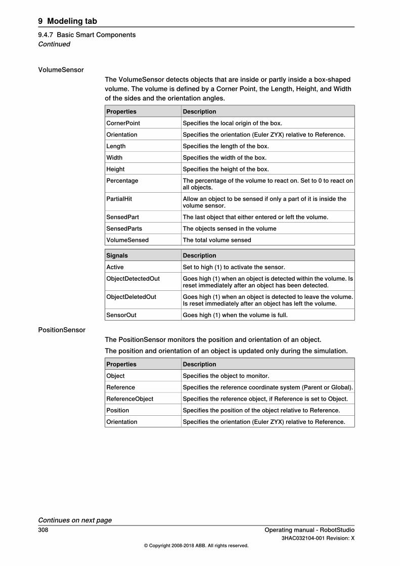
VolumeSensorThe VolumeSensor detects objects that are inside or partly inside a box-shapedvolume. The volume is defined by a Corner Point, the Length, Height, and Widthof the sides and the orientation angles.
DescriptionProperties
Specifies the local origin of the box.CornerPoint
Specifies the orientation (Euler ZYX) relative to Reference.Orientation
Specifies the length of the box.Length
Specifies the width of the box.Width
Specifies the height of the box.Height
The percentage of the volume to react on. Set to 0 to react onall objects.
Percentage
Allow an object to be sensed if only a part of it is inside thevolume sensor.
PartialHit
The last object that either entered or left the volume.SensedPart
The objects sensed in the volumeSensedParts
The total volume sensedVolumeSensed
DescriptionSignals
Set to high (1) to activate the sensor.Active
Goes high (1) when an object is detected within the volume. Isreset immediately after an object has been detected.
ObjectDetectedOut
Goes high (1) when an object is detected to leave the volume.Is reset immediately after an object has left the volume.
ObjectDeletedOut
Goes high (1) when the volume is full.SensorOut
PositionSensorThe PositionSensor monitors the position and orientation of an object.The position and orientation of an object is updated only during the simulation.
DescriptionProperties
Specifies the object to monitor.Object
Specifies the reference coordinate system (Parent or Global).Reference
Specifies the reference object, if Reference is set to Object.ReferenceObject
Specifies the position of the object relative to Reference.Position
Specifies the orientation (Euler ZYX) relative to Reference.Orientation
Continues on next page308 Operating manual - RobotStudio
3HAC032104-001 Revision: X© Copyright 2008-2018 ABB. All rights reserved.
9 Modeling tab9.4.7 Basic Smart ComponentsContinued
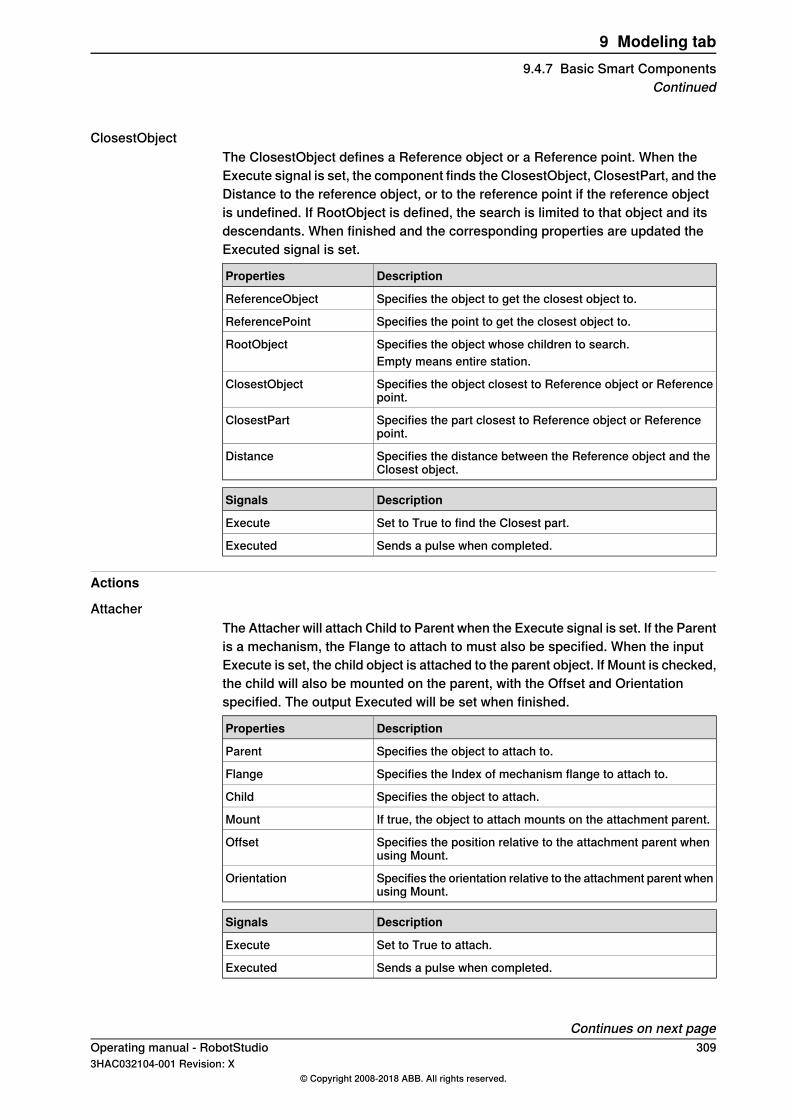
ClosestObjectThe ClosestObject defines a Reference object or a Reference point. When theExecute signal is set, the component finds the ClosestObject, ClosestPart, and theDistance to the reference object, or to the reference point if the reference objectis undefined. If RootObject is defined, the search is limited to that object and itsdescendants. When finished and the corresponding properties are updated theExecuted signal is set.
DescriptionProperties
Specifies the object to get the closest object to.ReferenceObject
Specifies the point to get the closest object to.ReferencePoint
Specifies the object whose children to search.RootObjectEmpty means entire station.
Specifies the object closest to Reference object or Referencepoint.
ClosestObject
Specifies the part closest to Reference object or Referencepoint.
ClosestPart
Specifies the distance between the Reference object and theClosest object.
Distance
DescriptionSignals
Set to True to find the Closest part.Execute
Sends a pulse when completed.Executed
Actions
AttacherThe Attacher will attach Child to Parent when the Execute signal is set. If the Parentis a mechanism, the Flange to attach to must also be specified. When the inputExecute is set, the child object is attached to the parent object. If Mount is checked,the child will also be mounted on the parent, with the Offset and Orientationspecified. The output Executed will be set when finished.
DescriptionProperties
Specifies the object to attach to.Parent
Specifies the Index of mechanism flange to attach to.Flange
Specifies the object to attach.Child
If true, the object to attach mounts on the attachment parent.Mount
Specifies the position relative to the attachment parent whenusing Mount.
Offset
Specifies the orientation relative to the attachment parent whenusing Mount.
Orientation
DescriptionSignals
Set to True to attach.Execute
Sends a pulse when completed.Executed
Continues on next pageOperating manual - RobotStudio 3093HAC032104-001 Revision: X
© Copyright 2008-2018 ABB. All rights reserved.
9 Modeling tab9.4.7 Basic Smart Components
Continued
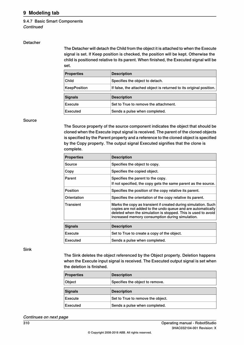
DetacherThe Detacher will detach the Child from the object it is attached to when the Executesignal is set. If Keep position is checked, the position will be kept. Otherwise thechild is positioned relative to its parent. When finished, the Executed signal will beset.
DescriptionProperties
Specifies the object to detach.Child
If false, the attached object is returned to its original position.KeepPosition
DescriptionSignals
Set to True to remove the attachment.Execute
Sends a pulse when completed.Executed
SourceThe Source property of the source component indicates the object that should becloned when the Execute input signal is received. The parent of the cloned objectsis specified by the Parent property and a reference to the cloned object is specifiedby the Copy property. The output signal Executed signifies that the clone iscomplete.
DescriptionProperties
Specifies the object to copy.Source
Specifies the copied object.Copy
Specifies the parent to the copy.ParentIf not specified, the copy gets the same parent as the source.
Specifies the position of the copy relative its parent.Position
Specifies the orientation of the copy relative its parent.Orientation
Marks the copy as transient if created during simulation. Suchcopies are not added to the undo queue and are automaticallydeleted when the simulation is stopped. This is used to avoidincreased memory consumption during simulation.
Transient
DescriptionSignals
Set to True to create a copy of the object.Execute
Sends a pulse when completed.Executed
SinkThe Sink deletes the object referenced by the Object property. Deletion happenswhen the Execute input signal is received. The Executed output signal is set whenthe deletion is finished.
DescriptionProperties
Specifies the object to remove.Object
DescriptionSignals
Set to True to remove the object.Execute
Sends a pulse when completed.Executed
Continues on next page310 Operating manual - RobotStudio
3HAC032104-001 Revision: X© Copyright 2008-2018 ABB. All rights reserved.
9 Modeling tab9.4.7 Basic Smart ComponentsContinued
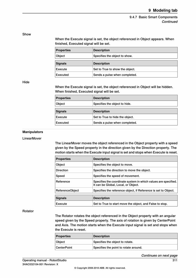
ShowWhen the Execute signal is set, the object referenced in Object appears. Whenfinished, Executed signal will be set.
DescriptionProperties
Specifies the object to show.Object
DescriptionSignals
Set to True to show the object.Execute
Sends a pulse when completed.Executed
HideWhen the Execute signal is set, the object referenced in Object will be hidden.When finished, Executed signal will be set.
DescriptionProperties
Specifies the object to hide.Object
DescriptionSignals
Set to True to hide the object.Execute
Sends a pulse when completed.Executed
Manipulators
LinearMoverThe LinearMover moves the object referenced in the Object property with a speedgiven by the Speed property in the direction given by the Direction property. Themotion starts when the Execute input signal is set and stops when Execute is reset.
DescriptionProperties
Specifies the object to move.Object
Specifies the direction to move the object.Direction
Specifies the speed of movement.Speed
Specifies the coordinate system in which values are specified.It can be Global, Local, or Object.
Reference
Specifies the reference object, if Reference is set to Object.ReferenceObject
DescriptionSignals
Set to True to start move the object, and False to stop.Execute
RotatorThe Rotator rotates the object referenced in the Object property with an angularspeed given by the Speed property. The axis of rotation is given by CenterPointand Axis. The motion starts when the Execute input signal is set and stops whenthe Execute is reset.
DescriptionProperties
Specifies the object to rotate.Object
Specifies the point to rotate around.CenterPoint
Continues on next pageOperating manual - RobotStudio 3113HAC032104-001 Revision: X
© Copyright 2008-2018 ABB. All rights reserved.
9 Modeling tab9.4.7 Basic Smart Components
Continued
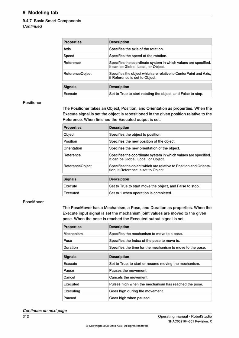
DescriptionProperties
Specifies the axis of the rotation.Axis
Specifies the speed of the rotation.Speed
Specifies the coordinate system in which values are specified.It can be Global, Local, or Object.
Reference
Specifies the object which are relative to CenterPoint and Axis,if Reference is set to Object.
ReferenceObject
DescriptionSignals
Set to True to start rotating the object, and False to stop.Execute
PositionerThe Positioner takes an Object, Position, and Orientation as properties. When theExecute signal is set the object is repositioned in the given position relative to theReference. When finished the Executed output is set.
DescriptionProperties
Specifies the object to position.Object
Specifies the new position of the object.Position
Specifies the new orientation of the object.Orientation
Specifies the coordinate system in which values are specified.It can be Global, Local, or Object.
Reference
Specifies the object which are relative to Position and Orienta-tion, if Reference is set to Object.
ReferenceObject
DescriptionSignals
Set to True to start move the object, and False to stop.Execute
Set to 1 when operation is completed.Executed
PoseMoverThe PoseMover has a Mechanism, a Pose, and Duration as properties. When theExecute input signal is set the mechanism joint values are moved to the givenpose. When the pose is reached the Executed output signal is set.
DescriptionProperties
Specifies the mechanism to move to a pose.Mechanism
Specifies the Index of the pose to move to.Pose
Specifies the time for the mechanism to move to the pose.Duration
DescriptionSignals
Set to True, to start or resume moving the mechanism.Execute
Pauses the movement.Pause
Cancels the movement.Cancel
Pulses high when the mechanism has reached the pose.Executed
Goes high during the movement.Executing
Goes high when paused.Paused
Continues on next page312 Operating manual - RobotStudio
3HAC032104-001 Revision: X© Copyright 2008-2018 ABB. All rights reserved.
9 Modeling tab9.4.7 Basic Smart ComponentsContinued
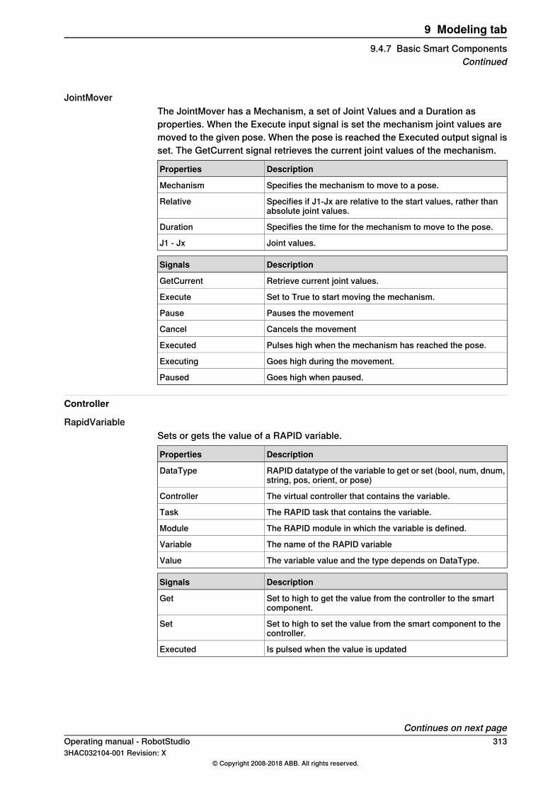
JointMoverThe JointMover has a Mechanism, a set of Joint Values and a Duration asproperties. When the Execute input signal is set the mechanism joint values aremoved to the given pose. When the pose is reached the Executed output signal isset. The GetCurrent signal retrieves the current joint values of the mechanism.
DescriptionProperties
Specifies the mechanism to move to a pose.Mechanism
Specifies if J1-Jx are relative to the start values, rather thanabsolute joint values.
Relative
Specifies the time for the mechanism to move to the pose.Duration
Joint values.J1 - Jx
DescriptionSignals
Retrieve current joint values.GetCurrent
Set to True to start moving the mechanism.Execute
Pauses the movementPause
Cancels the movementCancel
Pulses high when the mechanism has reached the pose.Executed
Goes high during the movement.Executing
Goes high when paused.Paused
Controller
RapidVariableSets or gets the value of a RAPID variable.
DescriptionProperties
RAPID datatype of the variable to get or set (bool, num, dnum,string, pos, orient, or pose)
DataType
The virtual controller that contains the variable.Controller
The RAPID task that contains the variable.Task
The RAPID module in which the variable is defined.Module
The name of the RAPID variableVariable
The variable value and the type depends on DataType.Value
DescriptionSignals
Set to high to get the value from the controller to the smartcomponent.
Get
Set to high to set the value from the smart component to thecontroller.
Set
Is pulsed when the value is updatedExecuted
Continues on next pageOperating manual - RobotStudio 3133HAC032104-001 Revision: X
© Copyright 2008-2018 ABB. All rights reserved.
9 Modeling tab9.4.7 Basic Smart Components
Continued
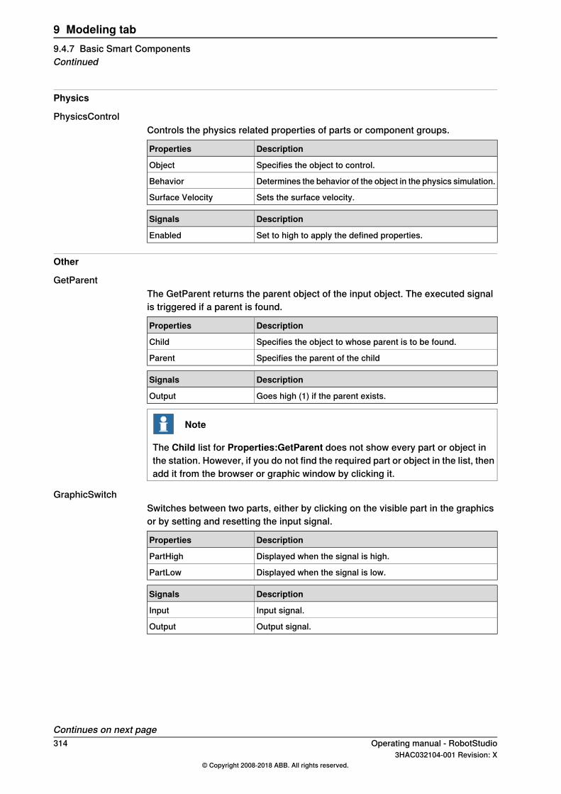
Physics
PhysicsControlControls the physics related properties of parts or component groups.
DescriptionProperties
Specifies the object to control.Object
Determines the behavior of the object in the physics simulation.Behavior
Sets the surface velocity.Surface Velocity
DescriptionSignals
Set to high to apply the defined properties.Enabled
Other
GetParentThe GetParent returns the parent object of the input object. The executed signalis triggered if a parent is found.
DescriptionProperties
Specifies the object to whose parent is to be found.Child
Specifies the parent of the childParent
DescriptionSignals
Goes high (1) if the parent exists.Output
Note
The Child list for Properties:GetParent does not show every part or object inthe station. However, if you do not find the required part or object in the list, thenadd it from the browser or graphic window by clicking it.
GraphicSwitchSwitches between two parts, either by clicking on the visible part in the graphicsor by setting and resetting the input signal.
DescriptionProperties
Displayed when the signal is high.PartHigh
Displayed when the signal is low.PartLow
DescriptionSignals
Input signal.Input
Output signal.Output
Continues on next page314 Operating manual - RobotStudio
3HAC032104-001 Revision: X© Copyright 2008-2018 ABB. All rights reserved.
9 Modeling tab9.4.7 Basic Smart ComponentsContinued
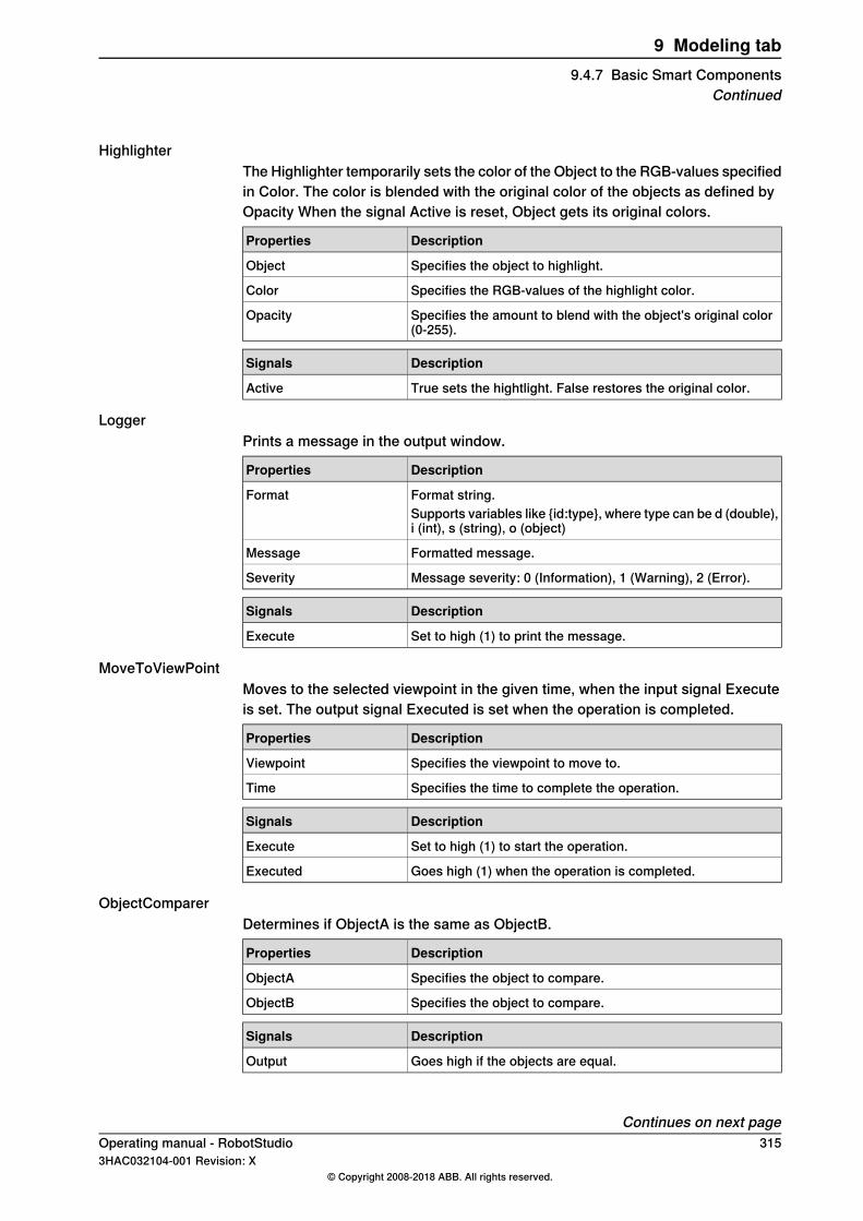
HighlighterThe Highlighter temporarily sets the color of the Object to the RGB-values specifiedin Color. The color is blended with the original color of the objects as defined byOpacity When the signal Active is reset, Object gets its original colors.
DescriptionProperties
Specifies the object to highlight.Object
Specifies the RGB-values of the highlight color.Color
Specifies the amount to blend with the object's original color(0-255).
Opacity
DescriptionSignals
True sets the hightlight. False restores the original color.Active
LoggerPrints a message in the output window.
DescriptionProperties
Format string.FormatSupports variables like {id:type}, where type can be d (double),i (int), s (string), o (object)
Formatted message.Message
Message severity: 0 (Information), 1 (Warning), 2 (Error).Severity
DescriptionSignals
Set to high (1) to print the message.Execute
MoveToViewPointMoves to the selected viewpoint in the given time, when the input signal Executeis set. The output signal Executed is set when the operation is completed.
DescriptionProperties
Specifies the viewpoint to move to.Viewpoint
Specifies the time to complete the operation.Time
DescriptionSignals
Set to high (1) to start the operation.Execute
Goes high (1) when the operation is completed.Executed
ObjectComparerDetermines if ObjectA is the same as ObjectB.
DescriptionProperties
Specifies the object to compare.ObjectA
Specifies the object to compare.ObjectB
DescriptionSignals
Goes high if the objects are equal.Output
Continues on next pageOperating manual - RobotStudio 3153HAC032104-001 Revision: X
© Copyright 2008-2018 ABB. All rights reserved.
9 Modeling tab9.4.7 Basic Smart Components
Continued
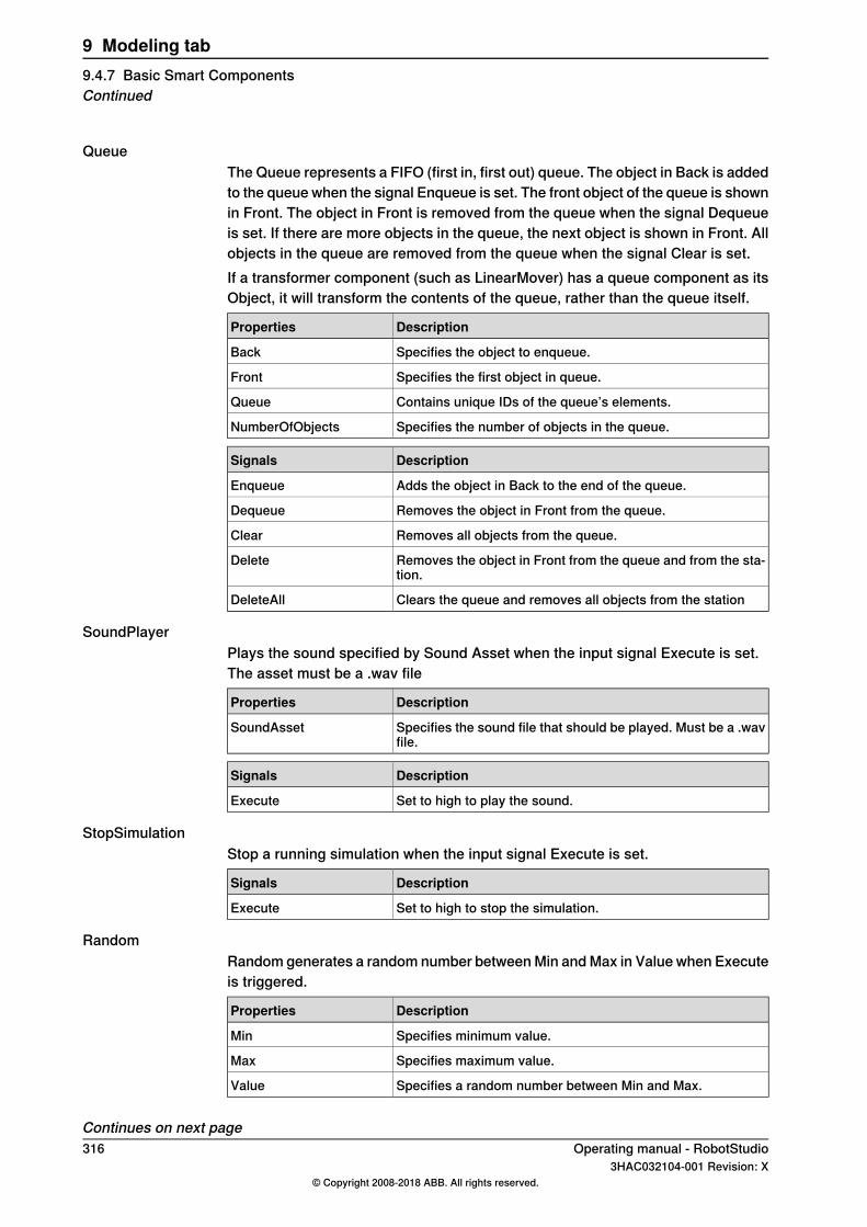
QueueThe Queue represents a FIFO (first in, first out) queue. The object in Back is addedto the queue when the signal Enqueue is set. The front object of the queue is shownin Front. The object in Front is removed from the queue when the signal Dequeueis set. If there are more objects in the queue, the next object is shown in Front. Allobjects in the queue are removed from the queue when the signal Clear is set.If a transformer component (such as LinearMover) has a queue component as itsObject, it will transform the contents of the queue, rather than the queue itself.
DescriptionProperties
Specifies the object to enqueue.Back
Specifies the first object in queue.Front
Contains unique IDs of the queue’s elements.Queue
Specifies the number of objects in the queue.NumberOfObjects
DescriptionSignals
Adds the object in Back to the end of the queue.Enqueue
Removes the object in Front from the queue.Dequeue
Removes all objects from the queue.Clear
Removes the object in Front from the queue and from the sta-tion.
Delete
Clears the queue and removes all objects from the stationDeleteAll
SoundPlayerPlays the sound specified by Sound Asset when the input signal Execute is set.The asset must be a .wav file
DescriptionProperties
Specifies the sound file that should be played. Must be a .wavfile.
SoundAsset
DescriptionSignals
Set to high to play the sound.Execute
StopSimulationStop a running simulation when the input signal Execute is set.
DescriptionSignals
Set to high to stop the simulation.Execute
RandomRandom generates a random number between Min and Max in Value when Executeis triggered.
DescriptionProperties
Specifies minimum value.Min
Specifies maximum value.Max
Specifies a random number between Min and Max.Value
Continues on next page316 Operating manual - RobotStudio
3HAC032104-001 Revision: X© Copyright 2008-2018 ABB. All rights reserved.
9 Modeling tab9.4.7 Basic Smart ComponentsContinued
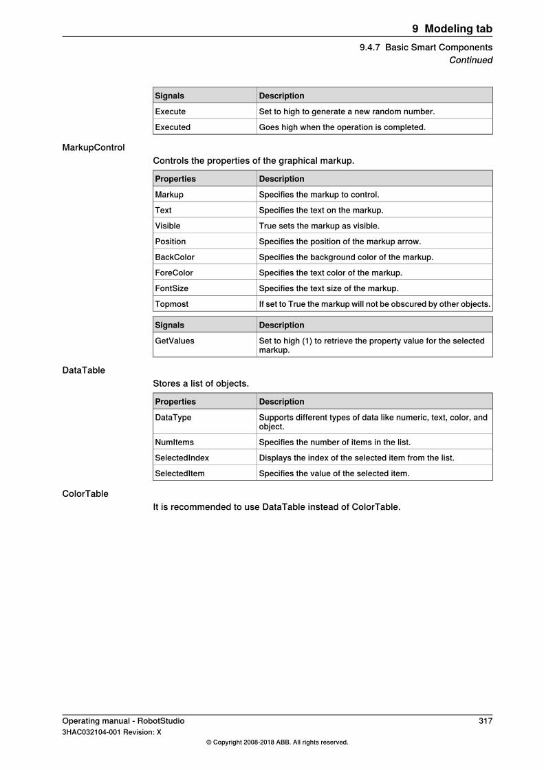
DescriptionSignals
Set to high to generate a new random number.Execute
Goes high when the operation is completed.Executed
MarkupControlControls the properties of the graphical markup.
DescriptionProperties
Specifies the markup to control.Markup
Specifies the text on the markup.Text
True sets the markup as visible.Visible
Specifies the position of the markup arrow.Position
Specifies the background color of the markup.BackColor
Specifies the text color of the markup.ForeColor
Specifies the text size of the markup.FontSize
If set to True the markup will not be obscured by other objects.Topmost
DescriptionSignals
Set to high (1) to retrieve the property value for the selectedmarkup.
GetValues
DataTableStores a list of objects.
DescriptionProperties
Supports different types of data like numeric, text, color, andobject.
DataType
Specifies the number of items in the list.NumItems
Displays the index of the selected item from the list.SelectedIndex
Specifies the value of the selected item.SelectedItem
ColorTableIt is recommended to use DataTable instead of ColorTable.
Operating manual - RobotStudio 3173HAC032104-001 Revision: X
© Copyright 2008-2018 ABB. All rights reserved.
9 Modeling tab9.4.7 Basic Smart Components
Continued
9.4.8 Property Editor
OverviewThe Property editor is used to modify the values of dynamic properties and I/Osignals for a Smart Component. By default, the Property editor is displayed as atool window to the left.Each dynamic property is represented by a control. The type of control that isdisplayed depends on the property type and property attributes.Properties with the Hidden flag set to true are not displayed. Read-only propertiescannot be modified but are only displayed.The values are validated according to the property attributes. If an invalid value isentered, an error icon is displayed next to the control and the Apply button isdisabled.If you set the AutoApply attribute of a property to true, the value is appliedwhenever you change the value in the control. You can apply the values of otherproperties by clicking theApply button. If the component has no properties withoutAutoApply, then the Apply button will never be enabled.You can toggle the value of a digital signal by clicking the control. Similarly, youcan change the value of an analog or group signal by entering the new value inthe text box.
Opening the Property editorYou can open the Property editor dialog box in any one of the following ways:
• Right-click context menu for a Smart Component and select Properties.• Launches automatically when the Smart Component Editor is started.• Launched when you add a base component. See Basic Smart Components
on page 300.
318 Operating manual - RobotStudio3HAC032104-001 Revision: X
© Copyright 2008-2018 ABB. All rights reserved.
9 Modeling tab9.4.8 Property Editor
9.4.9 The Simulation Watch window
OverviewThe Simulation Watch allows you to monitor the values of dynamic properties andI/O signals in Smart Components. It specifies the simulation that should be pausedwhen a value changes or meets a condition.
Layout of the Simulation Watch windowThe Simulation Watch window by default takes the lower tab area in the RobotStudioGUI.The window contains a list view of four columns with one row for each watch item:
DescriptionWatch item
Specifies the Simulation break point and Break Condition.BreakFor more information, see Setting Breakpoints on page 320.
Specifies the object that owns the property or signal (for stationsignals the name of the station is displayed).
Object
Specifies the watched property or signal.Property/Signal
Specifies the current value of the property or signal.Value
Adding and Deleting the Watch itemsUse this procedure to add or delete a watch item.
Note
As a prerequisite, you should add smart component, its properties and signals.For more information, see Smart Component Editor on page 289.
1 In the Simulation Watch window, right-click and select Add to display theAdd submenu.The Add submenu displays a recursive view of all the smart components,their properties and signals. The top level submenu displays the stationsignals.
Note
Watch items that are already watched are not displayed in the recursiveview.
2 From the Add submenu, select property or signal to add a single propertyor signal of a component.
3 From the Add submenu, select Add all to add all the properties and signalsof a component.
Continues on next pageOperating manual - RobotStudio 3193HAC032104-001 Revision: X
© Copyright 2008-2018 ABB. All rights reserved.
9 Modeling tab9.4.9 The Simulation Watch window
4 In the Simulation Watch window, right-click on the row of the watch itemand select Delete to delete one or more watch items.
Note
The Watch items are saved in the station and are restored when the stationis opened.
Setting BreakpointsYou can set the breakpoint in one of the following ways:
1 To set the simulation breakpoint, select the check box next to a watch item.
Note
By default, the simulation is paused whenever the value of the property orsignal changes.
2 In the Simulation Watch window, right-click on the row of the watch itemand select Break Condition.The Break Condition dialog box appears.
• Set the simulation to paused, when the value meets a certain logicalcondition. The condition can be viewed in the Break column of theWatch window.
• When a breakpoint is reached, the simulation is paused which isindicated by both the Play and Stop buttons being enabled.
• If the Simulation Watch window is hidden behind the other windows,it is brought to the front and the text of the corresponding watch itemturns red.
Note
• Break condition can be specified only for the properties of numericand string types, and not for the object types.
• After the current simulation time step is completed, all the remainingSmart component events are executed before the simulation is actuallypaused.
320 Operating manual - RobotStudio3HAC032104-001 Revision: X
© Copyright 2008-2018 ABB. All rights reserved.
9 Modeling tab9.4.9 The Simulation Watch windowContinued

9.5 Tags
OverviewFor a complex RobotStudio station containing many robots, parts, paths, targetsand other objects the browser and the 3D graphics view becomes cluttered. Tagsfunction helps the user to identify objects in the cluttered 3D graphics view and inthe browser during station modeling and offline programming.Using tags function, you can group objects in a defined structure by labeling them.It is possible to hide or show these tags independent of the other tags. A hiddentagged object is invisible in the browser and in the 3D graphics window unless itis labeled by a currently visible tag.
Tip
For easy and quick access of Tags function, add it to the Quick Access Toolbarusing the customize Commands.
Creating a New TagUse any of the following steps to create a new tag.
• In the Modeling tab, select Tags and then click New Tag.• Right-click the object and in the context menu, click Tags and then clickNew
Tag. The object will be labeled by the tagThe new tag appears in the browser with the default name. Press F2 and selectRename from the context menu to rename the tag.Use any of the following steps to hide or show tagged objects.
• In the Tag browser, right-click the tag and then check/uncheck Visible.• Click the Tags menu and then check/uncheck the tag to show/hide the tag.
Tag VisibilityWhen a tag is invisible/ unchecked, the corresponding tagged object will be hiddenin the 3D graphicas view and in the browsers (layout, path and targets, modeling).If an object is labeled by several tags, the object will be visible when at least oneof the tags is set visible. Untagged objects are always visible.
Note
The regular visible property remains and overrides the tag visibility. If regularvisible property is unchecked for an object, the object will be hidden in the 3Dgraphics view but it is visible in the browser. For a tagged object, when thevisibility is unchecked, the object will be hidden in the 3D graphics view and inthe browser.
Operating manual - RobotStudio 3213HAC032104-001 Revision: X
© Copyright 2008-2018 ABB. All rights reserved.
9 Modeling tab9.5 Tags

9.6 Selection of Objects
OverviewIn 3D view, you can select an object by drawing a selection rectangle using a mousecursor.
Deep rectangle selectionThe Deep rectangle selection (default selection mode) is enabled if you press andhold the SHIFT key and draw a rectangle in the 3D view using the mouse. Thismode selects objects covered by the selection rectangle regardless of its visibility.
Shallow rectangle selectionShallow rectangle selection is enabled if you press SHIFT + S keys and draw arectangle in the 3D view using the mouse. In this mode, you can optionally selectthe currently visible object.
322 Operating manual - RobotStudio3HAC032104-001 Revision: X
© Copyright 2008-2018 ABB. All rights reserved.
9 Modeling tab9.6 Selection of Objects

9.7 Solid
Creating a solid1 Click Solid and then click the type of solid you want to create to bring up a
dialog box.2 Enter requested values in the dialog box and click Create. For detailed
information about the specific dialog box for the curve to create, see below:
The Create Box dialog box
AB
C
D
xx060000
Select the Reference coordinate system to which all positionsor points will be related.
Reference
Click in one of these boxes, and then click the corner point inthe graphics window to transfer the values to the Corner Pointboxes, or type the position. The corner point will be the localorigin of the box.
Corner Point (A)
If the object shall be rotated relative to the reference coordinatesystem, specify the rotation.
Orientation
Specify the box dimension along its X axis.Length (B)
Specify the box dimension along its Y axis.Width (C)
Specify the box dimension along its Z axis.Height (D)
The Create Box from 3-Points dialog box
A
C
B
xx060001
Select the Reference coordinate system to which all positionsor points will be related.
Reference
Continues on next pageOperating manual - RobotStudio 3233HAC032104-001 Revision: X
© Copyright 2008-2018 ABB. All rights reserved.
9 Modeling tab9.7 Solid

This point will be the local origin of the box.Corner Point (A)Either type the position, or click in one of the boxes and thenselect the point in the graphics window.
This point is the the corner, diagonal to the local origin. It setsthe X and Y directions of the local coordinate system, as wellas the dimension of the box along these axes.
Point on diagonal of XY-plane (B)es
Either type the position, or click in one of the boxes and thenselect the point in the graphics window.
This point is the corner above the local origin, It sets the Zdirection of the local coordinate system, as well as the dimen-sion of the box along the Z axis.
Indication Point Z-axis (C)
Either type the position, or click in one of the boxes and thenselect the point in the graphics window.
The Create Cone dialog box
AB
C
xx060002
Select the Reference coordinate system to which all positionsor points will be related.
Reference
Click in one of these boxes, and then click the center point inthe graphics window to transfer the values to the Base CenterPoint boxes, or type the position. The center point will be thelocal origin of the cone.
Base Center Point (A)
If the object shall be rotated relative to the reference coordinatesystem, specify the rotation.
Orientation
Specify the radius of the cone.Radius (B)
Specify the diameter of the cone.Diameter
Specify the height of the cone.Height (C)
The Create Cylinder dialog box
A
C
B
xx060003
Continues on next page324 Operating manual - RobotStudio
3HAC032104-001 Revision: X© Copyright 2008-2018 ABB. All rights reserved.
9 Modeling tab9.7 SolidContinued

Select the Reference coordinate system to which all positionsor points will be related.
Reference
Click in one of these boxes, and then click the center point inthe graphics window to transfer the values to the Base CenterPoint boxes, or type the position. The center point will be thelocal origin of the cylinder.
Base Center Point (A)
If the object shall be rotated relative to the reference coordinatesystem, specify the rotation.
Orientation
Specify the radius of the cylinder.Radius (B)
Specify the diameter of the cylinder.Diameter
Specify the height of the cylinder.Height (C)
Select the checkbox to create a cylinder with rounded ends.Create Capsule
The Create Pyramid dialog box
A
B
C
xx060004
Select the Reference coordinate system to which all positionsor points will be related.
Reference
Click in one of these boxes, and then click the center point inthe graphics window to transfer the values to the Base CenterPoint boxes, or type the position. The center point will be thelocal origin of the pyramid.
Base Center Point (A)
If the object shall be rotated relative to the reference coordinatesystem, specify the rotation.
Orientation
Either type the position, or click in the box and then select thepoint in the graphics window.
Center to Corner Point (B)
Specify the height of the pyramid.Height (C)
Specify the number of sides of the pyramid. The maximumnumber of sides is 50.
Number of Sides
Continues on next pageOperating manual - RobotStudio 3253HAC032104-001 Revision: X
© Copyright 2008-2018 ABB. All rights reserved.
9 Modeling tab9.7 SolidContinued
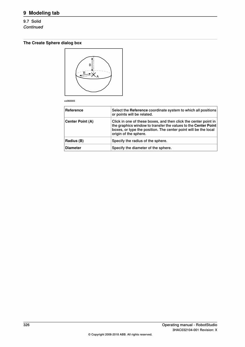
The Create Sphere dialog box
B
A
B
xx060005
Select the Reference coordinate system to which all positionsor points will be related.
Reference
Click in one of these boxes, and then click the center point inthe graphics window to transfer the values to the Center Pointboxes, or type the position. The center point will be the localorigin of the sphere.
Center Point (A)
Specify the radius of the sphere.Radius (B)
Specify the diameter of the sphere.Diameter
326 Operating manual - RobotStudio3HAC032104-001 Revision: X
© Copyright 2008-2018 ABB. All rights reserved.
9 Modeling tab9.7 SolidContinued
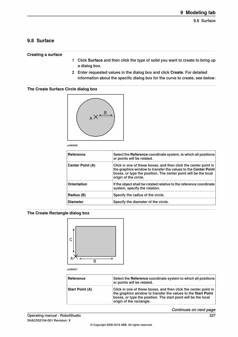
9.8 Surface
Creating a surface1 Click Surface and then click the type of solid you want to create to bring up
a dialog box.2 Enter requested values in the dialog box and click Create. For detailed
information about the specific dialog box for the curve to create, see below:
The Create Surface Circle dialog box
A
B
xx060006
Select theReference coordinate system, to which all positionsor points will be related.
Reference
Click in one of these boxes, and then click the center point inthe graphics window to transfer the values to the Center Pointboxes, or type the position. The center point will be the localorigin of the circle.
Center Point (A)
If the object shall be rotated relative to the reference coordinatesystem, specify the rotation.
Orientation
Specify the radius of the circle.Radius (B)
Specify the diameter of the circle.Diameter
The Create Rectangle dialog box
AB
C
xx060007
Select the Reference coordinate system to which all positionsor points will be related.
Reference
Click in one of these boxes, and then click the center point inthe graphics window to transfer the values to the Start Pointboxes, or type the position. The start point will be the localorigin of the rectangle.
Start Point (A)
Continues on next pageOperating manual - RobotStudio 3273HAC032104-001 Revision: X
© Copyright 2008-2018 ABB. All rights reserved.
9 Modeling tab9.8 Surface
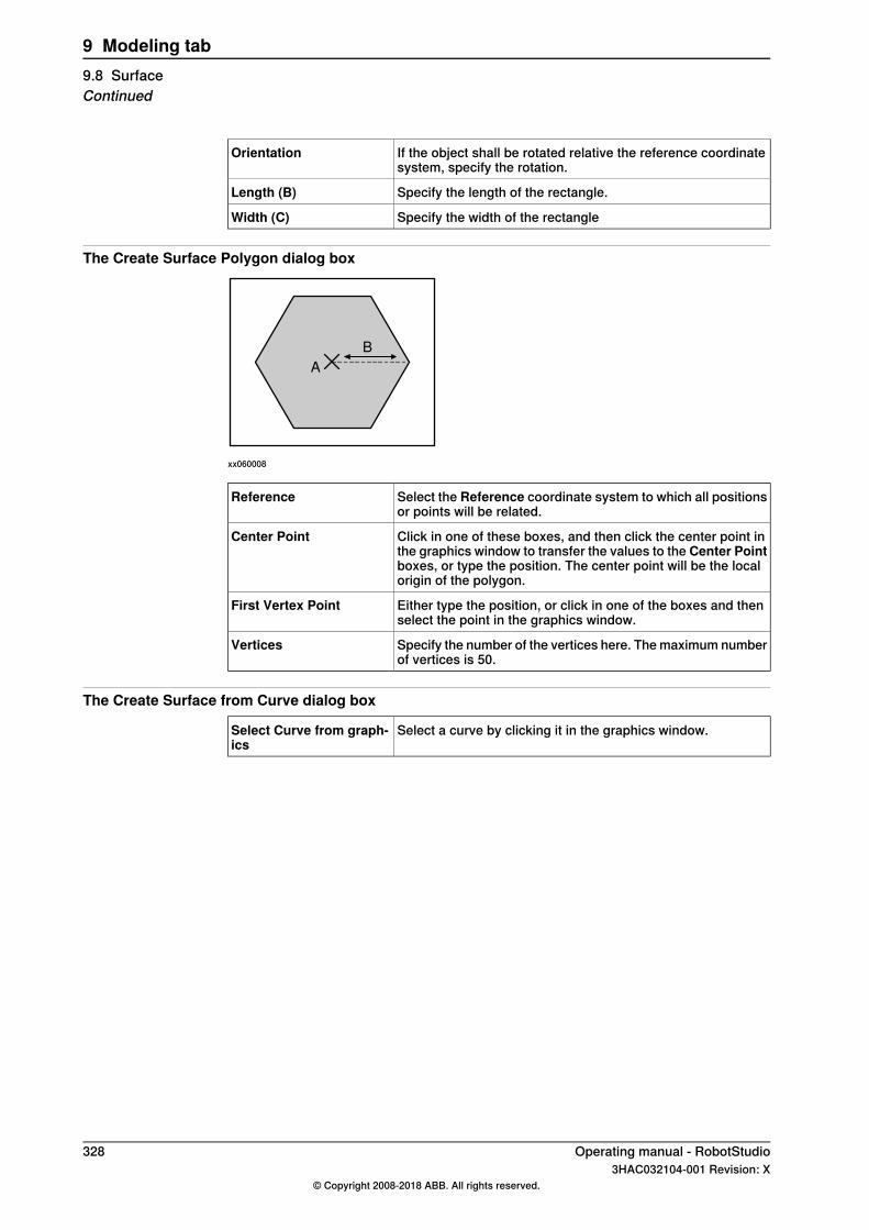
If the object shall be rotated relative the reference coordinatesystem, specify the rotation.
Orientation
Specify the length of the rectangle.Length (B)
Specify the width of the rectangleWidth (C)
The Create Surface Polygon dialog box
A
B
xx060008
Select the Reference coordinate system to which all positionsor points will be related.
Reference
Click in one of these boxes, and then click the center point inthe graphics window to transfer the values to the Center Pointboxes, or type the position. The center point will be the localorigin of the polygon.
Center Point
Either type the position, or click in one of the boxes and thenselect the point in the graphics window.
First Vertex Point
Specify the number of the vertices here. The maximum numberof vertices is 50.
Vertices
The Create Surface from Curve dialog box
Select a curve by clicking it in the graphics window.Select Curve from graph-ics
328 Operating manual - RobotStudio3HAC032104-001 Revision: X
© Copyright 2008-2018 ABB. All rights reserved.
9 Modeling tab9.8 SurfaceContinued
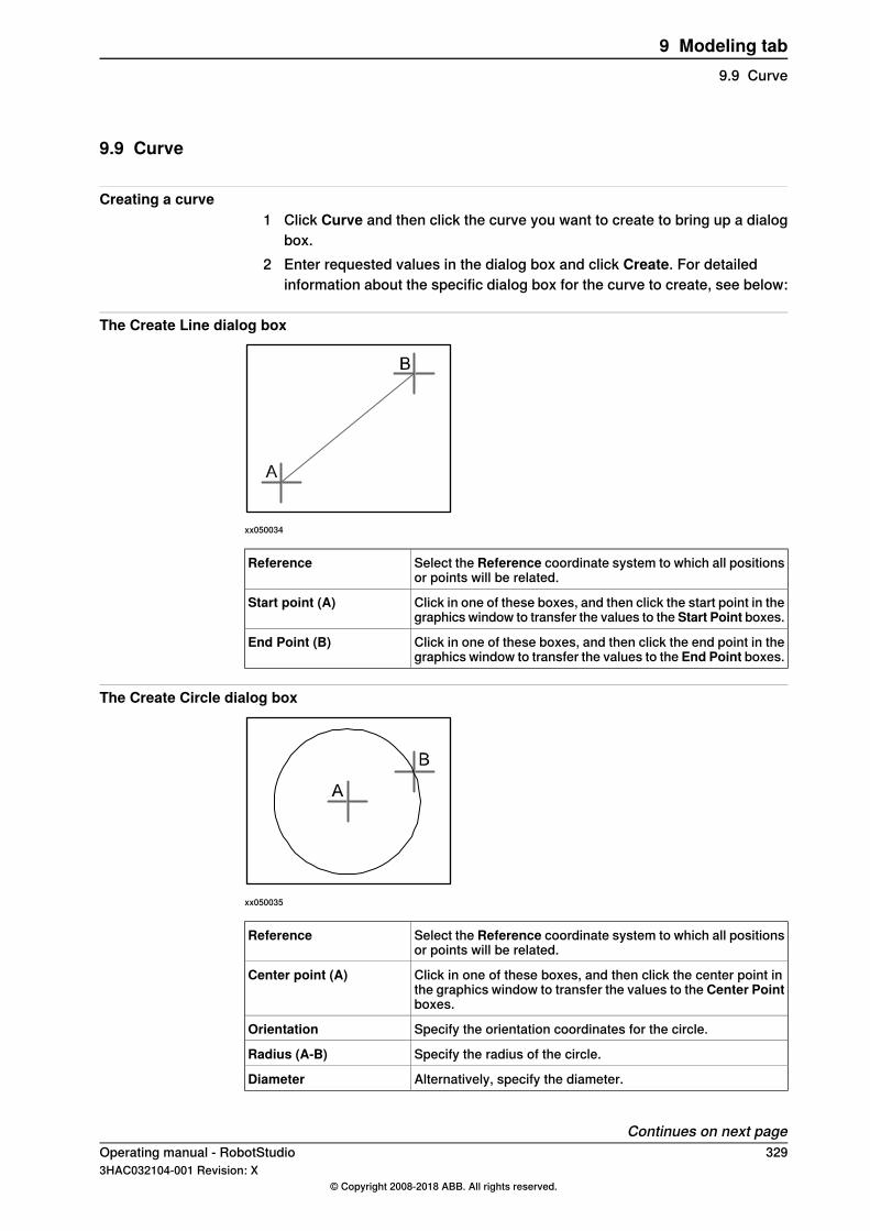
9.9 Curve
Creating a curve1 Click Curve and then click the curve you want to create to bring up a dialog
box.2 Enter requested values in the dialog box and click Create. For detailed
information about the specific dialog box for the curve to create, see below:
The Create Line dialog box
xx050034
Select the Reference coordinate system to which all positionsor points will be related.
Reference
Click in one of these boxes, and then click the start point in thegraphics window to transfer the values to the Start Point boxes.
Start point (A)
Click in one of these boxes, and then click the end point in thegraphics window to transfer the values to the End Point boxes.
End Point (B)
The Create Circle dialog box
xx050035
Select the Reference coordinate system to which all positionsor points will be related.
Reference
Click in one of these boxes, and then click the center point inthe graphics window to transfer the values to the Center Pointboxes.
Center point (A)
Specify the orientation coordinates for the circle.Orientation
Specify the radius of the circle.Radius (A-B)
Alternatively, specify the diameter.Diameter
Continues on next pageOperating manual - RobotStudio 3293HAC032104-001 Revision: X
© Copyright 2008-2018 ABB. All rights reserved.
9 Modeling tab9.9 Curve

The Create Three Points Circle dialog box
xx050036
Select the Reference coordinate system to which all positionsor points will be related.
Reference
Click in one of these boxes, and then click the first point in thegraphics window to transfer the values to the First Point boxes.
First Point (A)
Click in one of these boxes, and then click the second point inthe graphics window to transfer the values to the Second Pointboxes.
Second Point (B)
Click in one of these boxes, and then click the third point inthe graphics window to transfer the values to the Third Pointboxes.
Third Point (C)
The Create Arc dialog box
xx050037
Select the Reference coordinate system to which all positionsor points will be related.
Reference
Click in one of these boxes, and then click the start point in thegraphics window to transfer the values to the Start Point boxes.
Start Point (A)
Click in one of these boxes, and then click the second point inthe graphics window to transfer the values to the Mid Pointboxes.
Mid Point (B)
Click in one of these boxes, and then click the end point in thegraphics window to transfer the values to the End Point boxes.
End Point (C)
Continues on next page330 Operating manual - RobotStudio
3HAC032104-001 Revision: X© Copyright 2008-2018 ABB. All rights reserved.
9 Modeling tab9.9 CurveContinued

The Create Elliptical Arc dialog box
xx050038
Select the Reference coordinate system to which all positionsor points will be related.
Reference
Click in one of these boxes, and then click the center point inthe graphics window to transfer the values to the Center Pointboxes.
Center Point (A)
Click in one of these boxes, and then click the end point forthe major axis of the ellipse in the graphics window to transferthe values to the Major Axis End Point boxes.
Major Axis End Point (B)
Click in one of these boxes, and then click the end point forthe minor axis of the ellipse in the graphics window to transferthe values to the Minor Axis End Point boxes.
Minor Axis End Point (C)
Specify the start angle for the arc, measured from the majoraxis.
Start Angle (α)
Specify the end angle for the arc, measured from the majoraxis.
End Angle (β)
The Create Ellipse dialog box
xx050039
Select the Reference coordinate system to which all positionsor points will be related.
Reference
Click in one of the Center Point boxes, and then click thecenter point in the graphics window to transfer the values tothe Center Point boxes.
Center Point (A)
Click in one of these boxes, and then click the end point forthe major axis of the ellipse in the graphics window to transferthe values to the Major Axis End Point boxes.
Major Axis End Point (B)
Specify the length of the minor axis of the ellipse. The minorradius will be created perpendicular to the major axis.
Minor Radius (C)
Continues on next pageOperating manual - RobotStudio 3313HAC032104-001 Revision: X
© Copyright 2008-2018 ABB. All rights reserved.
9 Modeling tab9.9 CurveContinued

The Create Rectangle dialog box
xx050040
Select the Reference coordinate system to which all positionsor points will be related.
Reference
Click in one of these boxes, and then click the start point in thegraphics window to transfer the values to the Start Point boxes.The rectangle will be created in the positive coordinate direc-tions.
Start Point (A)
Specify the orientation coordinates for the rectangle.Orientation
Specify the length of the rectangle along the x axis.Length (B)
Specify the width of the rectangle along the y axis.Width (C)
The Create Polygon dialog box
xx050041
Select the Reference coordinate system to which all positionsor points will be related.
Reference
Click in one of these boxes, and then click the center point inthe graphics window to transfer the values to the Center Pointboxes.
Center Point (A)
Click in one of these boxes, and then click the first vertex pointin the graphics window to transfer the values to the First VertexPoint boxes. The distance between the center point and thefirst vertex point will be used for all vertex points.
First Vertex Point (B)
Specify the number of points to be used when creating thepolygon. The maximum number of vertices is 50.
Vertices
Continues on next page332 Operating manual - RobotStudio
3HAC032104-001 Revision: X© Copyright 2008-2018 ABB. All rights reserved.
9 Modeling tab9.9 CurveContinued

The Create Polyline dialog box
xx050042
Select the Reference coordinate system to which all positionsor points will be related.
Reference
Specify each node of the polyline here, one at a time, by eithertyping the values, or by clicking in one of these boxes, andthen selecting the point in the graphics window to transfer itscoordinates.
Point Coordinates
Click this button to add a point and its coordinates to the list.Add
Click this button to modify an already defined point, after youhave selected it in the list and entered new values.
Modify
The nodes of the polyline. To add more nodes, click Add New,click the desired point in the graphics window, and then clickAdd.
List
Select the checkbox to create a polyline that connects the startand end points.
Create closed curve
The Create Spline dialog box
xx050043
Select the Reference coordinate system to which all positionsor points will be related.
Reference
Specify each node of the spline here, one at a time, by eithertyping the values, or by clicking in one of these boxes, andthen selecting the point in the graphics window to transfer itscoordinates.
Point Coordinates
Click this button to add a point and its coordinates to the list.Add
Click this button to modify an already defined point, after youhave selected it in the list and entered new values.
Modify
Continues on next pageOperating manual - RobotStudio 3333HAC032104-001 Revision: X
© Copyright 2008-2018 ABB. All rights reserved.
9 Modeling tab9.9 CurveContinued
This nodes of the spline. To add more nodes, click Add New,click the desired point in the graphics window, and then clickAdd.
List
Select the checkbox to create a spline that connects the firstand last node.
Create closed curve
334 Operating manual - RobotStudio3HAC032104-001 Revision: X
© Copyright 2008-2018 ABB. All rights reserved.
9 Modeling tab9.9 CurveContinued
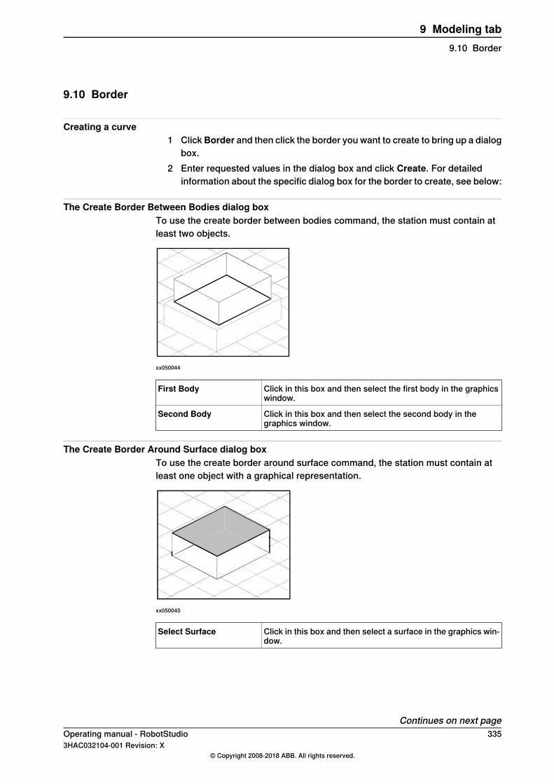
9.10 Border
Creating a curve1 ClickBorder and then click the border you want to create to bring up a dialog
box.2 Enter requested values in the dialog box and click Create. For detailed
information about the specific dialog box for the border to create, see below:
The Create Border Between Bodies dialog boxTo use the create border between bodies command, the station must contain atleast two objects.
xx050044
Click in this box and then select the first body in the graphicswindow.
First Body
Click in this box and then select the second body in thegraphics window.
Second Body
The Create Border Around Surface dialog boxTo use the create border around surface command, the station must contain atleast one object with a graphical representation.
xx050045
Click in this box and then select a surface in the graphics win-dow.
Select Surface
Continues on next pageOperating manual - RobotStudio 3353HAC032104-001 Revision: X
© Copyright 2008-2018 ABB. All rights reserved.
9 Modeling tab9.10 Border
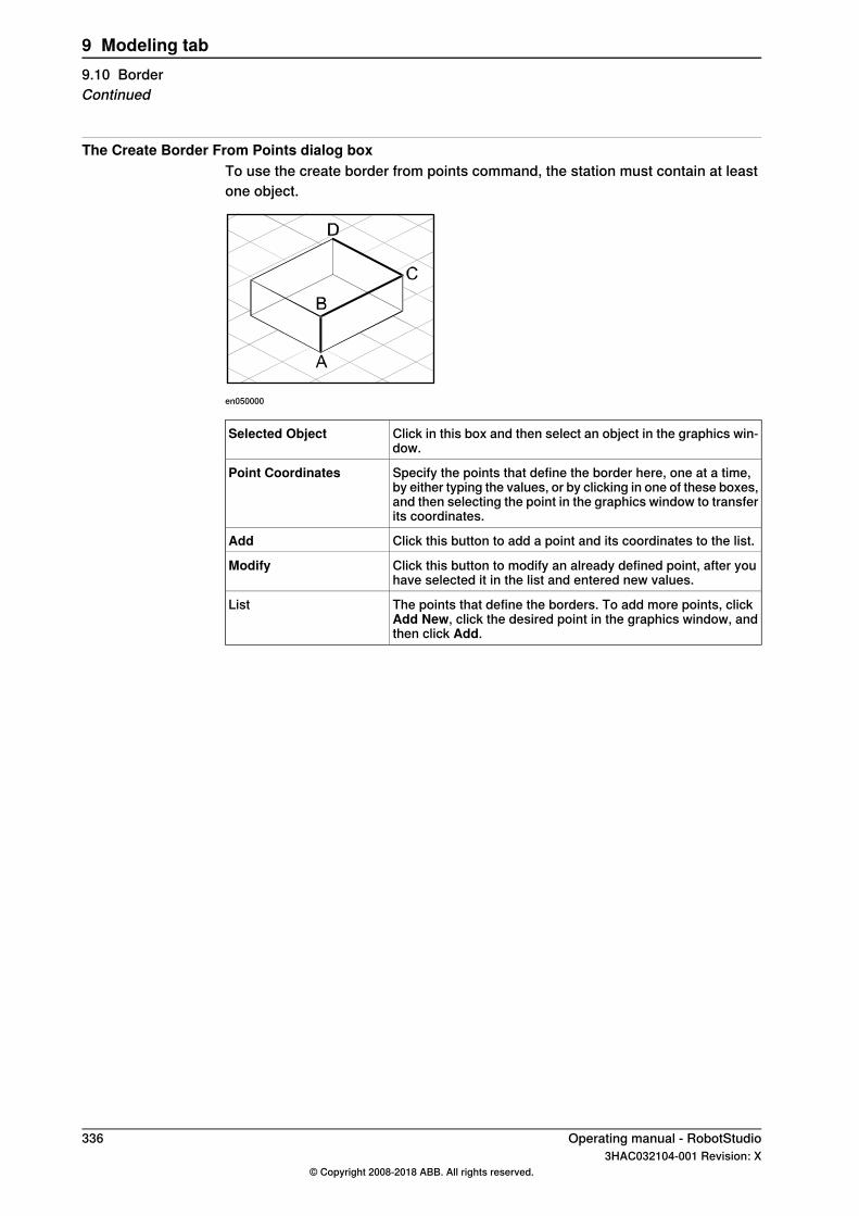
The Create Border From Points dialog boxTo use the create border from points command, the station must contain at leastone object.
en050000
Click in this box and then select an object in the graphics win-dow.
Selected Object
Specify the points that define the border here, one at a time,by either typing the values, or by clicking in one of these boxes,and then selecting the point in the graphics window to transferits coordinates.
Point Coordinates
Click this button to add a point and its coordinates to the list.Add
Click this button to modify an already defined point, after youhave selected it in the list and entered new values.
Modify
The points that define the borders. To add more points, clickAdd New, click the desired point in the graphics window, andthen click Add.
List
336 Operating manual - RobotStudio3HAC032104-001 Revision: X
© Copyright 2008-2018 ABB. All rights reserved.
9 Modeling tab9.10 BorderContinued

9.11 Intersect
The Intersect dialog box
A B
xx060009
Select this check box to keep the original bodies when creatingthe new body.
Keep Original
Select the body from which you want to make an intersection(A) by clicking it in the graphics window.
Intersect... (A)
Select the body with which you want to make an intersection(B) by clicking it in the graphics window.
...and (B)
A new body will be created based on the common area betweenthe selected bodies A and B.
Operating manual - RobotStudio 3373HAC032104-001 Revision: X
© Copyright 2008-2018 ABB. All rights reserved.
9 Modeling tab9.11 Intersect
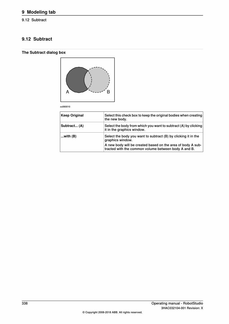
9.12 Subtract
The Subtract dialog box
A B
xx060010
Select this check box to keep the original bodies when creatingthe new body.
Keep Original
Select the body from which you want to subtract (A) by clickingit in the graphics window.
Subtract... (A)
Select the body you want to subtract (B) by clicking it in thegraphics window.
...with (B)
A new body will be created based on the area of body A sub-tracted with the common volume between body A and B.
338 Operating manual - RobotStudio3HAC032104-001 Revision: X
© Copyright 2008-2018 ABB. All rights reserved.
9 Modeling tab9.12 Subtract
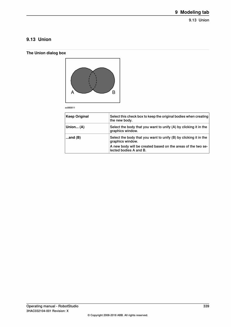
9.13 Union
The Union dialog box
A B
xx060011
Select this check box to keep the original bodies when creatingthe new body.
Keep Original
Select the body that you want to unify (A) by clicking it in thegraphics window.
Union... (A)
Select the body that you want to unify (B) by clicking it in thegraphics window.
...and (B)
A new body will be created based on the areas of the two se-lected bodies A and B.
Operating manual - RobotStudio 3393HAC032104-001 Revision: X
© Copyright 2008-2018 ABB. All rights reserved.
9 Modeling tab9.13 Union
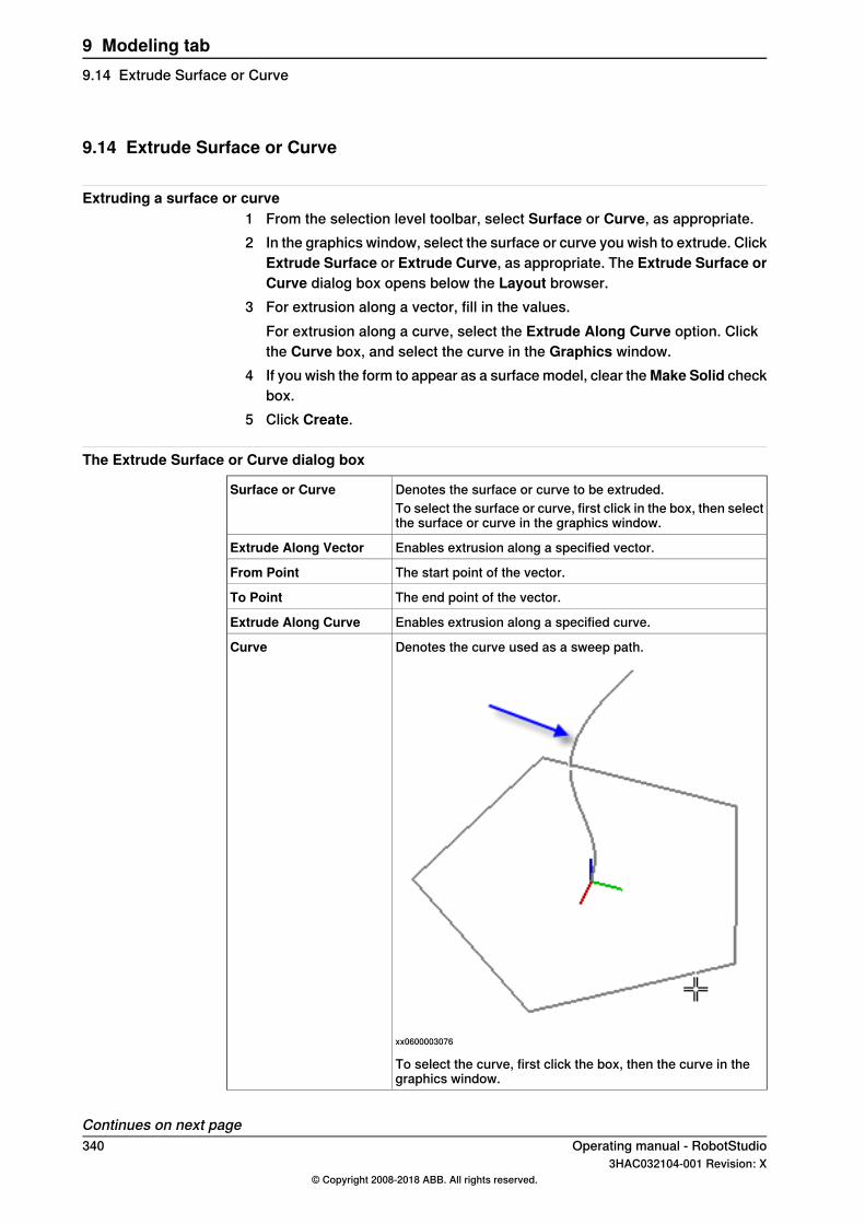
9.14 Extrude Surface or Curve
Extruding a surface or curve1 From the selection level toolbar, select Surface or Curve, as appropriate.2 In the graphics window, select the surface or curve you wish to extrude. Click
Extrude Surface or Extrude Curve, as appropriate. The Extrude Surface orCurve dialog box opens below the Layout browser.
3 For extrusion along a vector, fill in the values.For extrusion along a curve, select the Extrude Along Curve option. Clickthe Curve box, and select the curve in the Graphics window.
4 If you wish the form to appear as a surface model, clear theMake Solid checkbox.
5 Click Create.
The Extrude Surface or Curve dialog box
Denotes the surface or curve to be extruded.Surface or CurveTo select the surface or curve, first click in the box, then selectthe surface or curve in the graphics window.
Enables extrusion along a specified vector.Extrude Along Vector
The start point of the vector.From Point
The end point of the vector.To Point
Enables extrusion along a specified curve.Extrude Along Curve
Denotes the curve used as a sweep path.
xx0600003076
Curve
To select the curve, first click the box, then the curve in thegraphics window.
Continues on next page340 Operating manual - RobotStudio
3HAC032104-001 Revision: X© Copyright 2008-2018 ABB. All rights reserved.
9 Modeling tab9.14 Extrude Surface or Curve
Select this check box to convert the extruded form into a solid.Make Solid
Operating manual - RobotStudio 3413HAC032104-001 Revision: X
© Copyright 2008-2018 ABB. All rights reserved.
9 Modeling tab9.14 Extrude Surface or Curve
Continued
9.15 Line from Normal
Creating a line from normal1 Click Surface Selection.2 Click Line to Normal to bring up a dialog box.3 Click on a face to select it in the Select Face box.4 In the Length box, specify a length for the line.5 Optionally, select the Invert Normal check box to invert the direction of the
line.6 Click Create.
342 Operating manual - RobotStudio3HAC032104-001 Revision: X
© Copyright 2008-2018 ABB. All rights reserved.
9 Modeling tab9.15 Line from Normal
9.16 The Measure Group
Tip
Make sure to select the appropriate snap mode and selection levels beforemaking your measurements.
Measuring distances or angles1 Click the type of measurement you want to use:
SelectTo measure the
Point to pointdistance between two points you select in the graphicswindow.
Angleangle defined by three points you select in the graphicswindow.The first point to select is the converging point, thereafteryou shall select one point on each line.
Diameterdiameter, with the circle defined by three points you selectfrom the graphics window.
Minimum distanceclosest distance between two objects you select in thegraphics window.
The mouse pointer will turn into a ruler when you have activated any of themeasurement functions.
2 In the graphics window, select the points or objects to measure between.Information about the measuring points is displayed in the Output window.The results will be displayed in the Measurements tab in the Output windowwhen all points have been selected.
3 Optionally, repeat step 3 for making a new measurement of the same type.
Tip
You can also activate and deactivate the measurement functions from themeasurement toolbar.
Operating manual - RobotStudio 3433HAC032104-001 Revision: X
© Copyright 2008-2018 ABB. All rights reserved.
9 Modeling tab9.16 The Measure Group
9.17 Create Mechanism
Create a new mechanism1 Click Create Mechanism.
The Mechanism Modeler opens in create mode.2 In the Mechanism Model Name box, enter a mechanism name.3 From the Mechanism Type list, select a mechanism type.4 In the tree structure, right-click Links, and then click Add Link to bring up
the Create Link dialog box.A suggested name appears in the Link Name box.
5 In the Selected Part list, select a part (which will be highlighted in the graphicswindow) and click the arrow button to add the part to the Parts list box.The Selected Part list then automatically selects the next part, if any moreare available. Add these, as required.
Note
Parts that are part of a library or mechanism cannot be selected.
6 Select a part in the Parts list box, enter any values in the Selected Partsgroup boxes, and then click Apply to Part.Repeat for each part, as required.
7 Click OK.8 In the tree structure, right-click Joints, and then click Add Joint to bring up
the Create Joint dialog box.A suggested name appears in the Joint Name box.
9 Complete the Create Joint dialog box, and then click OK.10 In the tree structure, right-click Frame/Tool Data, and then click Add
Frame/Tool to bring up the Create Frame/Tool dialog box.A suggested name appears in the Frame/Tool Data name box.
11 Complete the Create Frame/Tool dialog box, and then click OK.The validity criteria for the Frame/Tool node are as follows:
12 In the tree structure, right-click Calibration, and then click Add Calibrationto bring up the Create Calibration dialog box.
13 Complete the Create Calibration dialog box, and then click OK.14 In the tree structure, right-clickDependency, and then clickAddDependency
to bring up the Create Dependency dialog box.15 Complete the Create Dependency dialog box, and then click OK.16 If all nodes are valid, compile the mechanism, see Compiling a mechanism
on page 345.
Create Conveyor1 Click Create Conveyor. The Create Conveyor browser opens.
Continues on next page344 Operating manual - RobotStudio
3HAC032104-001 Revision: X© Copyright 2008-2018 ABB. All rights reserved.
9 Modeling tab9.17 Create Mechanism
2 From the Conveyor Geometry list, select a geometry.3 In the Reference Frame, enter the base frame values (Position and
Orientation) relative to the World/local origin of the selected graphiccomponent.The Reference Frame defines the position where objects appear on theconveyor.
4 From the Type list, select the type of conveyor.
Note
Only linear conveyors are supported.
5 In the Conveyor length box, enter the length of the conveyor. The CreateMechanism gets enabled.
6 Click Create to create the conveyor.7 Build a new system using Building a new system on page 183.
In the System Options pane, scroll down to Motion Coordination and thenselect 606-1 Conveyor Tracking under Conveyor Control Options.
8 Create a new station using this new system.
Create connection between virtual controller and conveyor1 In the Modeling tab, click Create Connection.2 In the Create Connection tab, select the conveyor library in the Conveyor
list and then select the mechanical unit of the system.3 Set a suitable offset (base frame of the conveyor). This offset defines the
location of the base frame of the conveyor mechanical unit in relation to theConveyor reference frame.
4 Under the Connection Window, set appropriate values for Minimum andMaximum distances, and Start Window Width.
5 Under Base Frames, select the following options:• Select Station Values to update the virtual controller with the station
layout values.• Select Align Task Frame to move the task frame to the connection (to
align it with the base frame). The conveyor base frame will becomezero.
• Select Use Controller Values to update the station layout and the taskframe to match the virtual controller values.
6 Click Create.
Compiling a mechanismWhen compiling, a new mechanism, created in the create mode of the MechanismModeler, is added to the station with the default name "Mechanism_" followed byan index number.
Continues on next pageOperating manual - RobotStudio 3453HAC032104-001 Revision: X
© Copyright 2008-2018 ABB. All rights reserved.
9 Modeling tab9.17 Create Mechanism
Continued
When compiling, an existing editable mechanism, modified in the modify mode ofthe Mechanism Modeler, is saved without any poses, joint mapping ot transitiontimes.To compile a mechanism, follow these steps:
1 To compile a new or edited mechanism, click Compile Mechanism.The mechanism is inserted into the active station. The link parts are clonedwith new names, but the corresponding links will update their part references.When the Mechanism modeler is closed, these cloned parts will be removed.
2 The Mechanism Modeler now switches to modify mode. To complete themechanism, see below.
Completing or modifying a mechanismTo complete the modeling of a mechanism, follow these steps:
1 If the values in the Joint Mapping group are correct, click Set.2 Configure the Poses grid. To add a pose, click Add and then complete the
Create Pose dialog box. Click Apply, followed by OK.• To add a pose, click Add and then complete the Create Pose dialog
box. Click Apply, followed by OK.• To edit a pose, select it in the grid, click Edit, and then complete the
Modify Pose dialog box. Click OK.• To remove a pose, select it in the grid and then click Remove.
3 Click Edit Transition Times to edit transition times.4 Click Close.
The Create Mechanism dialog box
Specifies the model name of the mechanism.Mechanism Model Name
Specifies the mechanism type.Mechanism Type
The components of the mechanism in a tree structure. The treestructure will not be visible unless the mechanism is editable.Each node (link, joint, frame, calibration and dependency) canbe edited in its own dialog box, see below.
Tree structure
Click this button to compile the mechanism. This button willnot be visible unless the mechanism is editable and themechanism model name is valid.
Compile Mechanism
The Create Conveyor Mechanism dialog box
Specifies the reference coordinates, World, Local and UCS.Based on the selection, the position and orientation valueschange.
Reference
Specifies the part to be selected for the conveyor.Conveyor Geometry
Specifies the type of conveyor.Type
Specifies the length of the conveyor.Conveyor Length
Click this button to compile the mechanism. This button willnot be visible unless the mechanism is editable and themechanism model name is valid.
Create
Continues on next page346 Operating manual - RobotStudio
3HAC032104-001 Revision: X© Copyright 2008-2018 ABB. All rights reserved.
9 Modeling tab9.17 Create MechanismContinued
The Create/Modify Link dialog boxA link is a moving component of a mechanism. Selecting a link node will highlightit in the graphics window.
Specifies the name of the link.Link Name
Specifies the parts to add to the Part list box.Selected Part
The BaseLink is where the kinematical chain begins. This mustbe the parent of the first joint. A mechanism may have onlyone BaseLink.
Set as BaseLink
Adds a selected part to the Part list box.
xx060000
Click this button to remove a selected part from the Part listbox.
Remove Part
This group manipulates the transform of the selected part.Selected Part
Specify the position of the part.Part Position
Specify the orientation of the part.Part Orientation
Click this button to apply the settings to the part.Apply to Part
The Create/Modify Joint dialog boxA joint is the axis where two links move in relation to each other. The availableoptions are Rotational, Prismatic and Four Bar joint on page 348. Selecting a jointnode will display a yellow-green line in the graphics window.
Specifies the name of the joint.Joint Name
Specifies the joint type. The default option is Rotational.Changing the Joint Type clears the Joint Limits below.
Joint Type.
Specifies the parent link, usually the first joint of the mechan-ism.
Parent Link
Specifies the child link. To be valid, the parent and child linksmay not be identical to each other, and the pair must be unique.
Child Link
Select this check box to make the joint active. An active jointis one that a user can move, while an inactive joint is a slaveto an active joint.
Active
This group specifies the axis around or along which the childmoves.
Joint Axis
Specify the start point of the axis vector.First Position
Specify the end point of the axis vector.Second Position
Demonstrates how the child link moves along its axis.Jog Axis
Continues on next pageOperating manual - RobotStudio 3473HAC032104-001 Revision: X
© Copyright 2008-2018 ABB. All rights reserved.
9 Modeling tab9.17 Create Mechanism
Continued
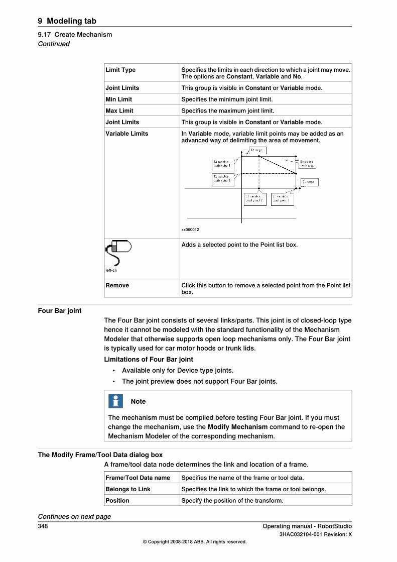
Specifies the limits in each direction to which a joint may move.The options are Constant, Variable and No.
Limit Type
This group is visible in Constant or Variable mode.Joint Limits
Specifies the minimum joint limit.Min Limit
Specifies the maximum joint limit.Max Limit
This group is visible in Constant or Variable mode.Joint Limits
In Variable mode, variable limit points may be added as anadvanced way of delimiting the area of movement.
xx060012
Variable Limits
Adds a selected point to the Point list box.
left-cli
Click this button to remove a selected point from the Point listbox.
Remove
Four Bar jointThe Four Bar joint consists of several links/parts. This joint is of closed-loop typehence it cannot be modeled with the standard functionality of the MechanismModeler that otherwise supports open loop mechanisms only. The Four Bar jointis typically used for car motor hoods or trunk lids.Limitations of Four Bar joint
• Available only for Device type joints.• The joint preview does not support Four Bar joints.
Note
The mechanism must be compiled before testing Four Bar joint. If you mustchange the mechanism, use the Modify Mechanism command to re-open theMechanism Modeler of the corresponding mechanism.
The Modify Frame/Tool Data dialog boxA frame/tool data node determines the link and location of a frame.
Specifies the name of the frame or tool data.Frame/Tool Data name
Specifies the link to which the frame or tool belongs.Belongs to Link
Specify the position of the transform.Position
Continues on next page348 Operating manual - RobotStudio
3HAC032104-001 Revision: X© Copyright 2008-2018 ABB. All rights reserved.
9 Modeling tab9.17 Create MechanismContinued
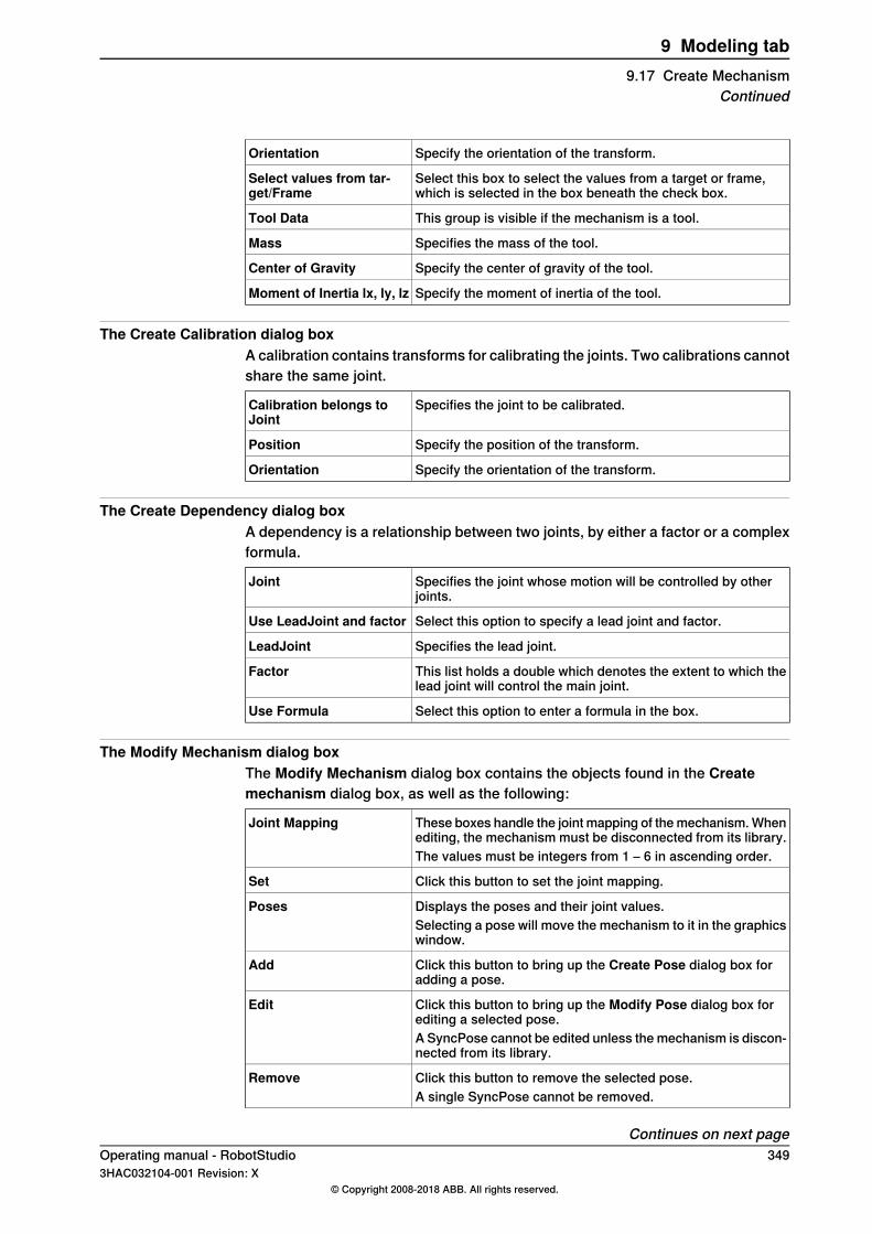
Specify the orientation of the transform.Orientation
Select this box to select the values from a target or frame,which is selected in the box beneath the check box.
Select values from tar-get/Frame
This group is visible if the mechanism is a tool.Tool Data
Specifies the mass of the tool.Mass
Specify the center of gravity of the tool.Center of Gravity
Specify the moment of inertia of the tool.Moment of Inertia lx, ly, lz
The Create Calibration dialog boxA calibration contains transforms for calibrating the joints. Two calibrations cannotshare the same joint.
Specifies the joint to be calibrated.Calibration belongs toJoint
Specify the position of the transform.Position
Specify the orientation of the transform.Orientation
The Create Dependency dialog boxA dependency is a relationship between two joints, by either a factor or a complexformula.
Specifies the joint whose motion will be controlled by otherjoints.
Joint
Select this option to specify a lead joint and factor.Use LeadJoint and factor
Specifies the lead joint.LeadJoint
This list holds a double which denotes the extent to which thelead joint will control the main joint.
Factor
Select this option to enter a formula in the box.Use Formula
The Modify Mechanism dialog boxThe Modify Mechanism dialog box contains the objects found in the Createmechanism dialog box, as well as the following:
These boxes handle the joint mapping of the mechanism. Whenediting, the mechanism must be disconnected from its library.
Joint Mapping
The values must be integers from 1 – 6 in ascending order.
Click this button to set the joint mapping.Set
Displays the poses and their joint values.PosesSelecting a pose will move the mechanism to it in the graphicswindow.
Click this button to bring up the Create Pose dialog box foradding a pose.
Add
Click this button to bring up the Modify Pose dialog box forediting a selected pose.
Edit
A SyncPose cannot be edited unless the mechanism is discon-nected from its library.
Click this button to remove the selected pose.RemoveA single SyncPose cannot be removed.
Continues on next pageOperating manual - RobotStudio 3493HAC032104-001 Revision: X
© Copyright 2008-2018 ABB. All rights reserved.
9 Modeling tab9.17 Create Mechanism
Continued
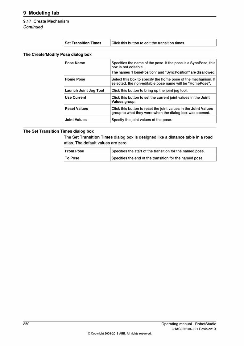
Click this button to edit the transition times.Set Transition Times
The Create/Modify Pose dialog box
Specifies the name of the pose. If the pose is a SyncPose, thisbox is not editable.
Pose Name
The names "HomePosition" and "SyncPosition" are disallowed.
Select this box to specify the home pose of the mechanism. Ifselected, the non-editable pose name will be "HomePose".
Home Pose
Click this button to bring up the joint jog tool.Launch Joint Jog Tool
Click this button to set the current joint values in the JointValues group.
Use Current
Click this button to reset the joint values in the Joint Valuesgroup to what they were when the dialog box was opened.
Reset Values
Specify the joint values of the pose.Joint Values
The Set Transition Times dialog boxThe Set Transition Times dialog box is designed like a distance table in a roadatlas. The default values are zero.
Specifies the start of the transition for the named pose.From Pose
Specifies the end of the transition for the named pose.To Pose
350 Operating manual - RobotStudio3HAC032104-001 Revision: X
© Copyright 2008-2018 ABB. All rights reserved.
9 Modeling tab9.17 Create MechanismContinued
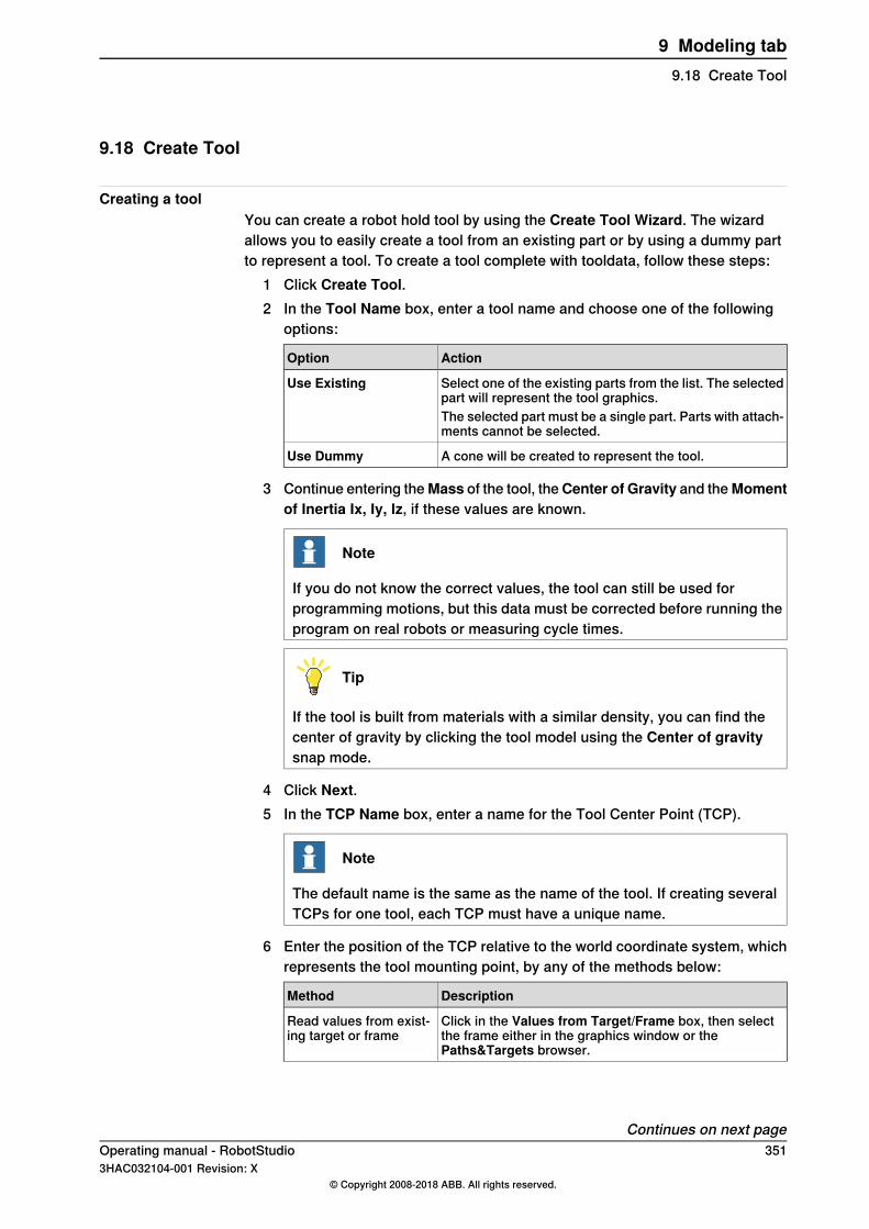
9.18 Create Tool
Creating a toolYou can create a robot hold tool by using the Create Tool Wizard. The wizardallows you to easily create a tool from an existing part or by using a dummy partto represent a tool. To create a tool complete with tooldata, follow these steps:
1 Click Create Tool.2 In the Tool Name box, enter a tool name and choose one of the following
options:
ActionOption
Select one of the existing parts from the list. The selectedpart will represent the tool graphics.
Use Existing
The selected part must be a single part. Parts with attach-ments cannot be selected.
A cone will be created to represent the tool.Use Dummy
3 Continue entering theMass of the tool, theCenter of Gravity and theMomentof Inertia Ix, Iy, Iz, if these values are known.
Note
If you do not know the correct values, the tool can still be used forprogramming motions, but this data must be corrected before running theprogram on real robots or measuring cycle times.
Tip
If the tool is built from materials with a similar density, you can find thecenter of gravity by clicking the tool model using the Center of gravitysnap mode.
4 Click Next.5 In the TCP Name box, enter a name for the Tool Center Point (TCP).
Note
The default name is the same as the name of the tool. If creating severalTCPs for one tool, each TCP must have a unique name.
6 Enter the position of the TCP relative to the world coordinate system, whichrepresents the tool mounting point, by any of the methods below:
DescriptionMethod
Click in the Values from Target/Frame box, then selectthe frame either in the graphics window or thePaths&Targets browser.
Read values from exist-ing target or frame
Continues on next pageOperating manual - RobotStudio 3513HAC032104-001 Revision: X
© Copyright 2008-2018 ABB. All rights reserved.
9 Modeling tab9.18 Create Tool
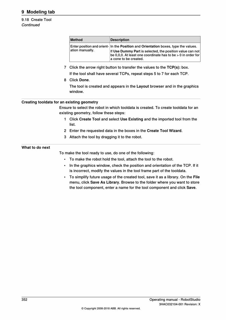
DescriptionMethod
In the Position and Orientation boxes, type the values.Enter position and orient-ation manually. If Use Dummy Part is selected, the position value can not
be 0,0,0. At least one coordinate has to be > 0 in order fora cone to be created.
7 Click the arrow right button to transfer the values to the TCP(s): box.If the tool shall have several TCPs, repeat steps 5 to 7 for each TCP.
8 Click Done.The tool is created and appears in the Layout browser and in the graphicswindow.
Creating tooldata for an existing geometryEnsure to select the robot in which tooldata is created. To create tooldata for anexisting geometry, follow these steps:
1 Click Create Tool and select Use Existing and the imported tool from thelist.
2 Enter the requested data in the boxes in the Create Tool Wizard.3 Attach the tool by dragging it to the robot.
What to do nextTo make the tool ready to use, do one of the following:
• To make the robot hold the tool, attach the tool to the robot.• In the graphics window, check the position and orientation of the TCP. If it
is incorrect, modify the values in the tool frame part of the tooldata.• To simplify future usage of the created tool, save it as a library. On the File
menu, click Save As Library. Browse to the folder where you want to storethe tool component, enter a name for the tool component and click Save.
352 Operating manual - RobotStudio3HAC032104-001 Revision: X
© Copyright 2008-2018 ABB. All rights reserved.
9 Modeling tab9.18 Create ToolContinued

9.19 Physics Tools
OverviewUse the Physics feature to include physics simulation together with the traditionalrobot simulation/programming tools. When you apply physics behavior to variousRobotStudio objects like, joints, cable, parts and so on, they will follow the rulesof physics during simulation.
Note
Cable simulation works only for the 64 bit version of RobotStudio.
Creating a cable1 In the Modelling tab, in the Create group, click Cable to create a cable, the
Create Cable pane opens, set cable properties like length, radius, materialand so on here.You can also create a cable from the Physics contextual tab.
2 Click in the station/robot to add the start and end points of the cable .3 Select a point on the cable, and drag it to add control point. You can also set
the control point in theCreate Cable pane. The control point can be any FreePoint or an Attached Point. You can attach the cable to any objects usingthe Attached to list box in the Create Cable pane.
4 Click Create, the new cable gets displayed in the Layout browser.
Setting the properties of materialsSelect one of the following options to set/edit the material of cable.
• In the Physics contextual tab, in Rigid Bodies group, click Material. ThePhysics Material pane opens. You can select your material either from thestandard material list or can use custom material. Click the Edit Materialsoption to edit material properties.
• In the Layout browser, right-click a part and then click Physics\Material\Material Properties to open the Physics Material pane. You can select yourmaterial either from the standard material list or can use custom material.Click the Edit Materials option to edit material properties.
Modifying length of a cable1 In the Layout browser, right-click cable, then clickModify Cable. TheModify
Cable pane opens.2 Edit the required parameter and click Apply.
Click options Shorter or Longer to stretch or skew the cable.
Continues on next pageOperating manual - RobotStudio 3533HAC032104-001 Revision: X
© Copyright 2008-2018 ABB. All rights reserved.
9 Modeling tab9.19 Physics Tools
Applying Behavior to objectsUse the behavior feature to set various motion related characteristic to aRobotStudio object. A physics object follows the rules of physics during simulation.In the Layout browser, right-click a part and then select Physics to set variousbehavior options.The following setting are possible.
• Inactive: This object will not interact with other objects during simulation.• Fixed: The position of the object remains fixed during simulation.• Kinematic: During simulation, RobotStudio controls the motion of the object.• Dynamic: During simulation the object follows rules of physics while in motion.
Similarly any joint created using the Physics Joint options will follow rules ofphysics. These options are Rotational joint, Prismatic joint, Ball joint and Lockjoint.
Applying Surface Velocity to a surfaceUse the Surface Velocity feature to create various surfaces with velocity inRobotStudio. The selected surface will follow the set velocity during simulation.
1 In the Layout browser, right-click a surface and then selectPhysics > SurfaceVelocity to set various velocity options.
2 In the left-side top tab, select the Enable Surface Velocity checkbox to enablesurface velocity on the selected surface.
3 Enter the required Speed.4 Select and enter the required Linear Direction.5 Select Control Points and Add Points to create the desired bends to the
selected surface.6 Click Apply.
354 Operating manual - RobotStudio3HAC032104-001 Revision: X
© Copyright 2008-2018 ABB. All rights reserved.
9 Modeling tab9.19 Physics ToolsContinued
10 Simulation tab10.1 Overview
The Simulation tabThe Simulation tab contains the controls for setting up, configuring, controlling,monitoring and recording simulations.
Operating manual - RobotStudio 3553HAC032104-001 Revision: X
© Copyright 2008-2018 ABB. All rights reserved.
10 Simulation tab10.1 Overview

10.2 Create Collision Set
OverviewA collision set contains two groups, Objects A and Objects B, in which you placethe objects to detect any collisions between them. When any object in Objects Acollides with any object in Objects B, the collision is displayed in the graphical viewand logged in the output window. You can have several collision sets in the station,but each collision set can only contain two groups.
Creating a collision set1 Click Create Collision Set to create a collision set in the Layout browser.2 Expand the collision set and then drag one of the objects to the ObjectsA
node to check for collisions.If you have several objects you want to check for collisions with objects inthe ObjectsB node, for example, the tool and the robot, drag all of them tothe ObjectsA node.
3 Drag the objects to the ObjectsB node to check for collisions.If you have several objects you want to check for collisions with objects inthe ObjectsA node, for example, the work piece and the fixture, drag all ofthem to he ObjectsB node.
Tip
Selecting a collision set or one of its groups (Objects A or Objects B) highlightsthe corresponding objects in the graphical window and the browser. Use thisfeature to quickly check what objects have been added to a collision set or toone of its groups.
356 Operating manual - RobotStudio3HAC032104-001 Revision: X
© Copyright 2008-2018 ABB. All rights reserved.
10 Simulation tab10.2 Create Collision Set
10.3 Simulation Setup
OverviewThe Simulation Setup dialog box is used to perform the following two main tasks.
• Setting up the sequence and entry point in the robot program• Creating simulation scenarios for different simulated objects
PrerequisitesTo set up a simulation, the following conditions must be met:
• At least one path must have been created in the station.• The paths to be simulated must have been synchronized to the virtual
controller.
Setup simulation paneFrom this pane, you can perform the combined task of configuring the programsequence and program execution such as entry point, and running the executionmode.You can create simulation scenarios containing different simulated objects andconnect each scenario with a predefined state to ensure that the correct state isapplied to all project objects before running the scenario. If you want to simulatea specific part or segment of the cell where not all simulated objects in the cell areincluded, you can set up a new scenario and add only the objects needed forsimulation.The Setup simulation pane consists of the following:
DescriptionOption
Lists all active station scenarios.• Add: Click to add a new scenario.• Remove: Click to delete the selected scenario.• Rename: Click to rename the selected scenario.
Active Simulation scen-ario
Initial state of the simulation.Initial state
Opens the Station Logic pane.Manage states
Displays all objects that can be part of a simulation. Objects thatutilize simulation time can be part of a simulation. For example,Virtual Controllers and Smart Components. When you create anew scenario, all objects are selected by default.
Simulated objects
• Time slice: This option makes RobotStudio always use thetime slice mode.
• Free run: This option makes RobotStudio always use thefree run mode.
Virtual time mode
Setting up a simulation1 Click Simulation Setup to bring up the Setup Simulation pane.2 Select the tasks to be active during simulation in the Select Active Tasks
box.3 Select the run mode as either Continuous or Single Cycle.4 From the Simulated Objects list select the task.
Continues on next pageOperating manual - RobotStudio 3573HAC032104-001 Revision: X
© Copyright 2008-2018 ABB. All rights reserved.
10 Simulation tab10.3 Simulation Setup

5 Select the entry point from the Entry point list.6 Click Edit to open the RAPID program where the user can edit the procedure.
Creating simulation scenarios1 Click Simulation Setup to bring up the Setup Simulation pane.2 Under Active Simulation Scenario ,
• Click Add to create a new scenario in the Simulated objects box.• Click Remove to delete the selected scenario from the Simulated
objects box.3 Select a saved state for the scenario from the Initial state list.
358 Operating manual - RobotStudio3HAC032104-001 Revision: X
© Copyright 2008-2018 ABB. All rights reserved.
10 Simulation tab10.3 Simulation SetupContinued
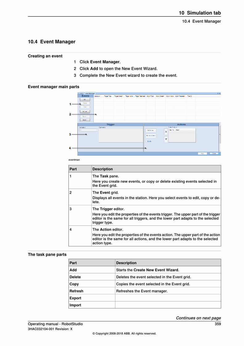
10.4 Event Manager
Creating an event1 Click Event Manager.2 Click Add to open the New Event Wizard.3 Complete the New Event wizard to create the event.
Event manager main parts
eventman
DescriptionPart
The Task pane.1Here you create new events, or copy or delete existing events selected inthe Event grid.
The Event grid.2Displays all events in the station. Here you select events to edit, copy or de-lete.
The Trigger editor.3Here you edit the properties of the events trigger. The upper part of the triggereditor is the same for all triggers, and the lower part adapts to the selectedtrigger type.
The Action editor.4Here you edit the properties of the events action. The upper part of the actioneditor is the same for all actions, and the lower part adapts to the selectedaction type.
The task pane parts
DescriptionPart
Starts the Create New Event Wizard.Add
Deletes the event selected in the Event grid.Delete
Copies the event selected in the Event grid.Copy
Refreshes the Event manager.Refresh
Export
Import
Continues on next pageOperating manual - RobotStudio 3593HAC032104-001 Revision: X
© Copyright 2008-2018 ABB. All rights reserved.
10 Simulation tab10.4 Event Manager
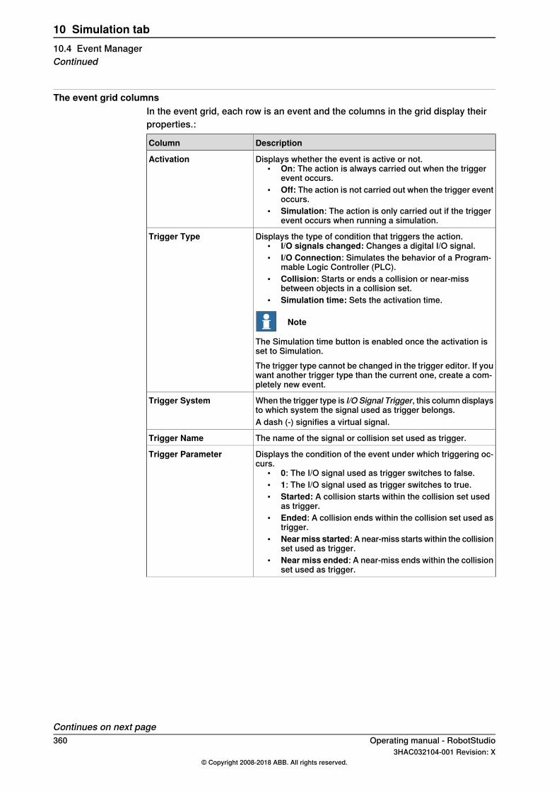
The event grid columnsIn the event grid, each row is an event and the columns in the grid display theirproperties.:
DescriptionColumn
Displays whether the event is active or not.• On: The action is always carried out when the trigger
event occurs.• Off: The action is not carried out when the trigger event
occurs.• Simulation: The action is only carried out if the trigger
event occurs when running a simulation.
Activation
Displays the type of condition that triggers the action.• I/O signals changed: Changes a digital I/O signal.• I/O Connection: Simulates the behavior of a Program-
mable Logic Controller (PLC).• Collision: Starts or ends a collision or near-miss
between objects in a collision set.• Simulation time: Sets the activation time.
Note
The Simulation time button is enabled once the activation isset to Simulation.
Trigger Type
The trigger type cannot be changed in the trigger editor. If youwant another trigger type than the current one, create a com-pletely new event.
When the trigger type is I/O Signal Trigger, this column displaysto which system the signal used as trigger belongs.
Trigger System
A dash (-) signifies a virtual signal.
The name of the signal or collision set used as trigger.Trigger Name
Displays the condition of the event under which triggering oc-curs.
• 0: The I/O signal used as trigger switches to false.• 1: The I/O signal used as trigger switches to true.• Started: A collision starts within the collision set used
as trigger.• Ended: A collision ends within the collision set used as
trigger.• Nearmiss started: A near-miss starts within the collision
set used as trigger.• Near miss ended: A near-miss ends within the collision
set used as trigger.
Trigger Parameter
Continues on next page360 Operating manual - RobotStudio
3HAC032104-001 Revision: X© Copyright 2008-2018 ABB. All rights reserved.
10 Simulation tab10.4 Event ManagerContinued

DescriptionColumn
Displays the action type that occurs in conjunction with thetrigger
• I/O Signal Action: Changes the value of a digital inputor output signal.
• Attach Object: Attaches an object to another.• Detach Object: Detaches an object from another.• TurnOn/Off SimulationMonitor: Toggles the simulation
monitor of a specific mechanism.• Turn On/Off Timer: Toggles the process timer.• MoveMechanism to Pose: Moves the selected mechan-
ism to a predefined pose and thereafter sends a stationsignal. Activates or deactivates the process timer.
• Move Graphical Object: Moves a graphical object to anew position and orientation.
• Show/Hide Graphical Object: Shows or hides thegraphical object.
• Do Nothing: No action occurs.• Multiple: The event triggers multiple actions, either all
at once or one at a time, each time the trigger is activ-ated. Each action can be viewed in the action editor.
Action Type
When the action type is Change I/O, this column displays thesystem to which the signal to change belongs.
Action System
A dash (-) signifies a virtual signal.
Displays the name of the signal to change, when the actiontype is Change I/O.
Action Name
Displays the condition after the action has occurred.• 0: The I/O signal will be set to false.• 1: The I/O signal will be set to true.• On: Turns the process timer on.• Off: Turns the process timer off.• Object1 -> Object2: Displays the object to which another
will be attached when the action type is Attach object.• Object1 <- Object2: Displays the object from which an-
other will be detached when the action type is Detachobject.
• Ended: A collision ends within the collision set used astrigger.
• Nearmiss started: A near-miss starts within the collisionset used as trigger.
• Near miss ended: A near-miss ends within the collisionset used as trigger.
• Multiple: Signifies multiple actions.
Action Parameter
Displays the time when the event trigger was executed.Time
Continues on next pageOperating manual - RobotStudio 3613HAC032104-001 Revision: X
© Copyright 2008-2018 ABB. All rights reserved.
10 Simulation tab10.4 Event Manager
Continued
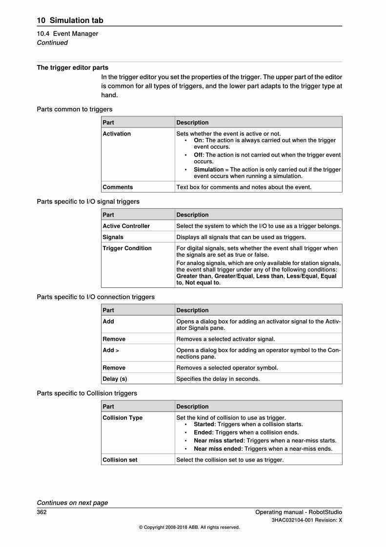
The trigger editor partsIn the trigger editor you set the properties of the trigger. The upper part of the editoris common for all types of triggers, and the lower part adapts to the trigger type athand.
Parts common to triggers
DescriptionPart
Sets whether the event is active or not.• On: The action is always carried out when the trigger
event occurs.• Off: The action is not carried out when the trigger event
occurs.• Simulation = The action is only carried out if the trigger
event occurs when running a simulation.
Activation
Text box for comments and notes about the event.Comments
Parts specific to I/O signal triggers
DescriptionPart
Select the system to which the I/O to use as a trigger belongs.Active Controller
Displays all signals that can be used as triggers.Signals
For digital signals, sets whether the event shall trigger whenthe signals are set as true or false.
Trigger Condition
For analog signals, which are only available for station signals,the event shall trigger under any of the following conditions:Greater than, Greater/Equal, Less than, Less/Equal, Equalto, Not equal to.
Parts specific to I/O connection triggers
DescriptionPart
Opens a dialog box for adding an activator signal to the Activ-ator Signals pane.
Add
Removes a selected activator signal.Remove
Opens a dialog box for adding an operator symbol to the Con-nections pane.
Add >
Removes a selected operator symbol.Remove
Specifies the delay in seconds.Delay (s)
Parts specific to Collision triggers
DescriptionPart
Set the kind of collision to use as trigger.• Started: Triggers when a collision starts.• Ended: Triggers when a collision ends.• Near miss started: Triggers when a near-miss starts.• Near miss ended: Triggers when a near-miss ends.
Collision Type
Select the collision set to use as trigger.Collision set
Continues on next page362 Operating manual - RobotStudio
3HAC032104-001 Revision: X© Copyright 2008-2018 ABB. All rights reserved.
10 Simulation tab10.4 Event ManagerContinued
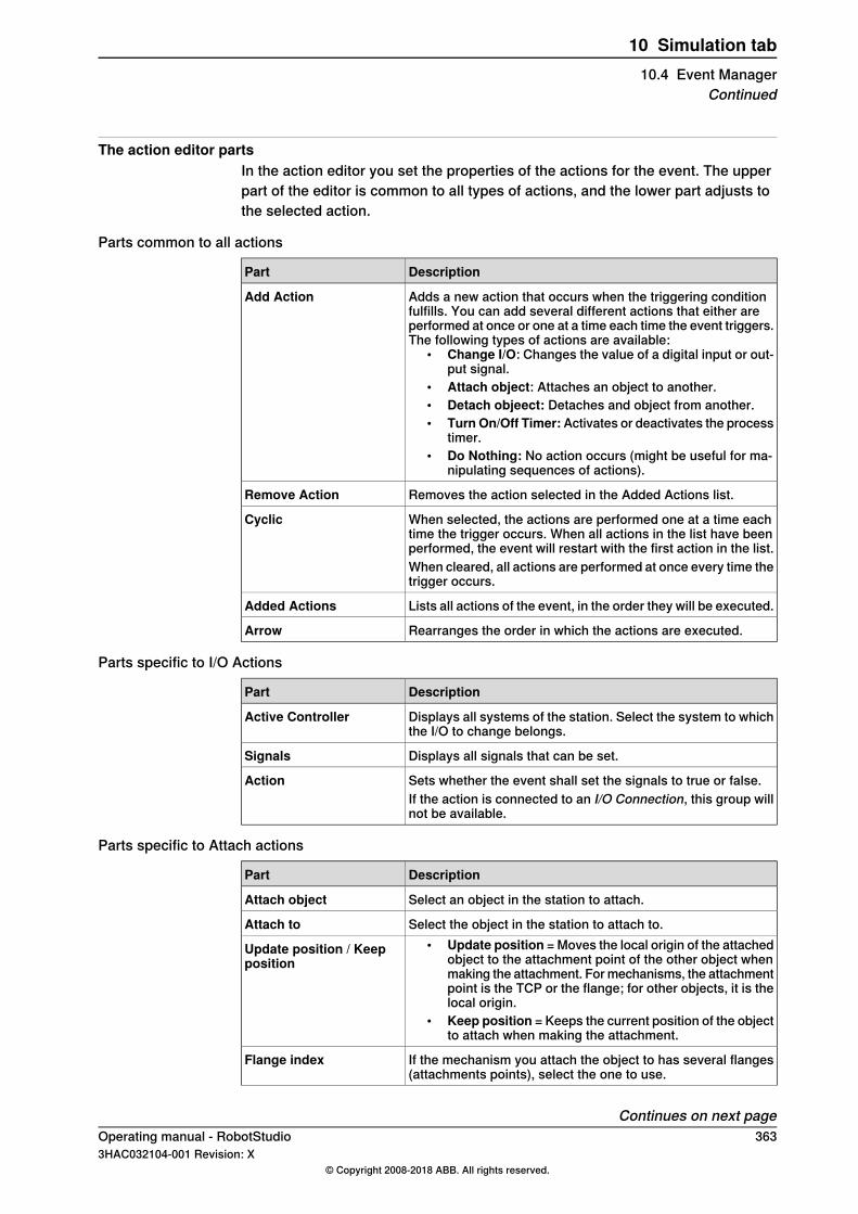
The action editor partsIn the action editor you set the properties of the actions for the event. The upperpart of the editor is common to all types of actions, and the lower part adjusts tothe selected action.
Parts common to all actions
DescriptionPart
Adds a new action that occurs when the triggering conditionfulfills. You can add several different actions that either areperformed at once or one at a time each time the event triggers.The following types of actions are available:
• Change I/O: Changes the value of a digital input or out-put signal.
• Attach object: Attaches an object to another.• Detach objeect: Detaches and object from another.• Turn On/Off Timer:Activates or deactivates the process
timer.• Do Nothing: No action occurs (might be useful for ma-
nipulating sequences of actions).
Add Action
Removes the action selected in the Added Actions list.Remove Action
When selected, the actions are performed one at a time eachtime the trigger occurs. When all actions in the list have beenperformed, the event will restart with the first action in the list.
Cyclic
When cleared, all actions are performed at once every time thetrigger occurs.
Lists all actions of the event, in the order they will be executed.Added Actions
Rearranges the order in which the actions are executed.Arrow
Parts specific to I/O Actions
DescriptionPart
Displays all systems of the station. Select the system to whichthe I/O to change belongs.
Active Controller
Displays all signals that can be set.Signals
Sets whether the event shall set the signals to true or false.ActionIf the action is connected to an I/O Connection, this group willnot be available.
Parts specific to Attach actions
DescriptionPart
Select an object in the station to attach.Attach object
Select the object in the station to attach to.Attach to• Update position = Moves the local origin of the attached
object to the attachment point of the other object whenmaking the attachment. For mechanisms, the attachmentpoint is the TCP or the flange; for other objects, it is thelocal origin.
• Keep position = Keeps the current position of the objectto attach when making the attachment.
Update position / Keepposition
If the mechanism you attach the object to has several flanges(attachments points), select the one to use.
Flange index
Continues on next pageOperating manual - RobotStudio 3633HAC032104-001 Revision: X
© Copyright 2008-2018 ABB. All rights reserved.
10 Simulation tab10.4 Event Manager
Continued

DescriptionPart
Optionally, specify an offset between the objects when makingthe attachment
Offset Position
Optionally, specify an offset between the objects when makingthe attachment
Offset Orientation
Parts specific to Detach actions
DescriptionPart
Select an object in the station to detach.Detach object
Select the object in the station to detach from.Detach from
Parts specific to Turn On/Off Simulation Monitor actions
DescriptionPart
Selects the mechanism.Mechanism
Sets whether the action shall start or stop the simulationmonitor function.
Turn Simulation MonitorOn/Off
Parts specific to Turn On/Off Timer actions
DescriptionPart
Sets whether the action shall start or stop the process timer.Turn On/Off Timer
Parts specific to Move Mechanism to Pose actions
DescriptionPart
Selects the mechanism.Mechanism
Selects between SyncPose and HomePose.Pose
Lists the station signals that are sent after the mechanismreaches its pose.
Station signal to set whenPose reached
Click this button to add a digital signal to the grid.Add Digital
Click this button to remove a digital signal from the grid.Remove
Parts specific to Move Graphical Object actions
DescriptionPart
Select a graphical object in the station to move.Graphical Object to Move
Sets the new position of the object.New Position
Sets the new orientation of the object.New Orientation
Parts specific to Show/Hide Graphical Object actions
DescriptionPart
Select a graphical object in the station.Graphical Object
Sets whether the object is shown or hidden.Show/Hide
364 Operating manual - RobotStudio3HAC032104-001 Revision: X
© Copyright 2008-2018 ABB. All rights reserved.
10 Simulation tab10.4 Event ManagerContinued

10.5 Station Logic
Introduction to Station LogicThe Station Logic has some of the characteristics of a Smart Component. It canbe used to work with these characteristics on the station level.The Station Logic editor consists of the following tabs similar to that of a SmartComponent editor:
• Compose• Properties and Bindings• Signals and Connections• View
For more information on the characteristics of a Smart Component editor, seeSmart Component on page 288.
Opening Station LogicYou can launch Station Logic in any of the following two ways:
• In the Simulation tab, click Reset and select Manage States.• In the Layout browser, right-click the station and select Station Logic.
Differences between Station Logic and Smart ComponentThe following table lists some of the differences while working with Station Logicand a Smart Component:
Station LogicSmart Component
The Editor window do not have the descrip-tion text box wherein the description can bemodified.
The Editor window consists of a text boxdisplaying the description of the componentthat is used for modifying the text.
The Compose tab has the following options:• Child components• Saved States
The Compose tab has the following options:• Child components• Saved States• Assets
The Properties and Bindings tab has thefollowing options:
• Property Bindings
The Properties and Bindings tab has thefollowing options:
• Dynamic Properties• Property Bindings
You can create connections to and from I/Osignals in a VC.
In the Signals and Connections tab, whenworking with Add or Edit I/O Connections,you do not have the option of selecting theVCs in the station from the theSourceObjectand Target Object list.
In the Signals and Connections tab, whenworking with Add or Edit I/O Connections,you have the option of selecting the VCs inthe station from the the Source Object andTarget Object list.
Operating manual - RobotStudio 3653HAC032104-001 Revision: X
© Copyright 2008-2018 ABB. All rights reserved.
10 Simulation tab10.5 Station Logic
10.6 Activate Mechanical Units
To activate or deactivate mechanical units manually1 Click Activate Mechanical Units to bring up a dialog box.2 In the Activate Mechanical Units dialog box, select the check boxes for the
mechanical units to set as active. When activating a mechanical unit thatshares a common drive unit, the other mechanical unit sharing that drive unitwill be deactivated automatically.
366 Operating manual - RobotStudio3HAC032104-001 Revision: X
© Copyright 2008-2018 ABB. All rights reserved.
10 Simulation tab10.6 Activate Mechanical Units

10.7 Simulation Control
Running a simulation1 In the Simulation Control group,
to...Click...
start and resume the simulation.• The Pause button is enabled once you start the
simulation• The Play button is changed to Resume once you
pause the simulation.• Click Resume to resume the simulation.
Play/Resume
start the simulation and to record it to a Station Viewer.Play and select Recordto Viewer The Save As dialog box appears where the simulation is
saved.
pause and step the simulation.• The Pause button is changed to Step once you start
the simulation.• Click Step to run the simulation in steps.
You can set the simulation timestep. See Options:Simula-tion:Clock on page 224.
Pause/Step
reset the simulation to its initial state. See Resetting sim-ulation on page 367.
Reset
Note
When running a simulation in time slice mode, all breakpoints set in theRAPID editor windows will be deactivated temporarily.
Note
During the simulation play, if a user does not want more objecs to be addedto the conveyor, in Layout browser, expand the conveyor node, thenright-click the object source and clear the Enabled option.
Resetting simulation1 In the Simulation Control group, click Reset to reset the simulation.2 ClickReset and select Save Current state to store states of objects and VCs
to be used in a simulation scenario. For more information, see Save CurrentState on page 291.
3 Click Reset and select Manage states to launch Station Logic. For moreinformation, see Station Logic on page 365.
Operating manual - RobotStudio 3673HAC032104-001 Revision: X
© Copyright 2008-2018 ABB. All rights reserved.
10 Simulation tab10.7 Simulation Control
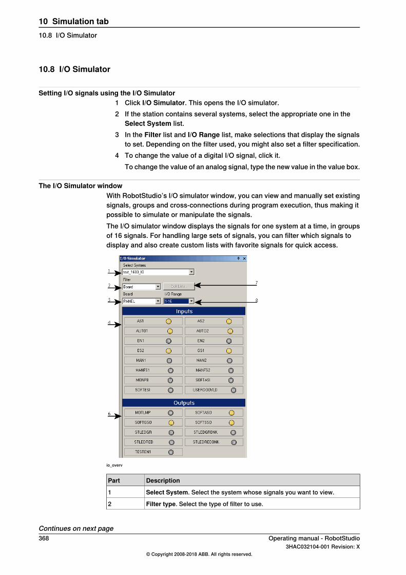
10.8 I/O Simulator
Setting I/O signals using the I/O Simulator1 Click I/O Simulator. This opens the I/O simulator.2 If the station contains several systems, select the appropriate one in the
Select System list.3 In the Filter list and I/O Range list, make selections that display the signals
to set. Depending on the filter used, you might also set a filter specification.4 To change the value of a digital I/O signal, click it.
To change the value of an analog signal, type the new value in the value box.
The I/O Simulator windowWith RobotStudio’s I/O simulator window, you can view and manually set existingsignals, groups and cross-connections during program execution, thus making itpossible to simulate or manipulate the signals.The I/O simulator window displays the signals for one system at a time, in groupsof 16 signals. For handling large sets of signals, you can filter which signals todisplay and also create custom lists with favorite signals for quick access.
io_overv
DescriptionPart
Select System. Select the system whose signals you want to view.1
Filter type. Select the type of filter to use.2
Continues on next page368 Operating manual - RobotStudio
3HAC032104-001 Revision: X© Copyright 2008-2018 ABB. All rights reserved.
10 Simulation tab10.8 I/O Simulator
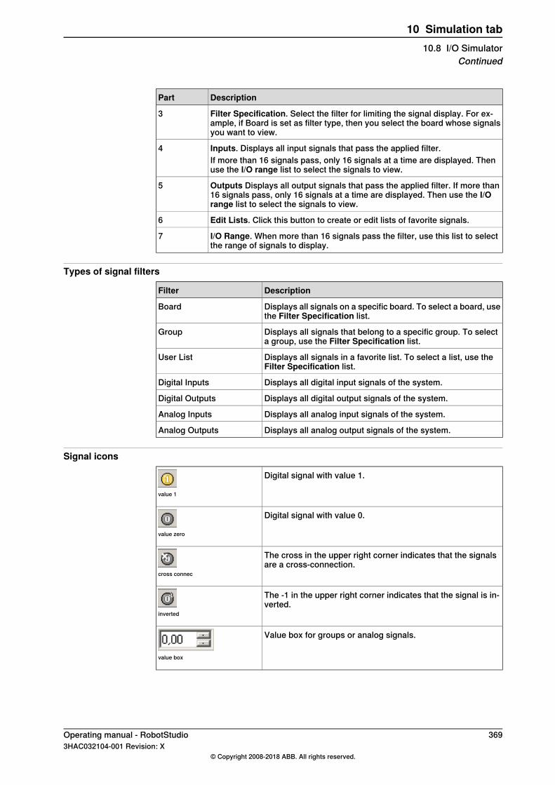
DescriptionPart
Filter Specification. Select the filter for limiting the signal display. For ex-ample, if Board is set as filter type, then you select the board whose signalsyou want to view.
3
Inputs. Displays all input signals that pass the applied filter.4If more than 16 signals pass, only 16 signals at a time are displayed. Thenuse the I/O range list to select the signals to view.
Outputs Displays all output signals that pass the applied filter. If more than16 signals pass, only 16 signals at a time are displayed. Then use the I/Orange list to select the signals to view.
5
Edit Lists. Click this button to create or edit lists of favorite signals.6
I/O Range. When more than 16 signals pass the filter, use this list to selectthe range of signals to display.
7
Types of signal filters
DescriptionFilter
Displays all signals on a specific board. To select a board, usethe Filter Specification list.
Board
Displays all signals that belong to a specific group. To selecta group, use the Filter Specification list.
Group
Displays all signals in a favorite list. To select a list, use theFilter Specification list.
User List
Displays all digital input signals of the system.Digital Inputs
Displays all digital output signals of the system.Digital Outputs
Displays all analog input signals of the system.Analog Inputs
Displays all analog output signals of the system.Analog Outputs
Signal icons
Digital signal with value 1.
value 1
Digital signal with value 0.
value zero
The cross in the upper right corner indicates that the signalsare a cross-connection.
cross connec
The -1 in the upper right corner indicates that the signal is in-verted.
inverted
Value box for groups or analog signals.
value box
Operating manual - RobotStudio 3693HAC032104-001 Revision: X
© Copyright 2008-2018 ABB. All rights reserved.
10 Simulation tab10.8 I/O Simulator
Continued

10.9 TCP Trace
The TCP Trace tab
Select this check box to activate tracing of the TCP path forthe selected robot.
Note
For TCP trace to work correctly, ensure that the workobjectsand tools used by the program are synchronized to the station.
Enable TCP Trace
Select this check box to activate tracing of moving workobject.Follow moving Workob-jects
Select this check box to remove the current trace when simu-lation starts.
Clear trace at simulationstart
You can set the color of the trace here.Primary color
Select this check box to assign a particular color to the TCPpath of the selected signal.
Color by signal
Select this button to define how the trace shall be colored. Asthe signal changes between the values defined in the Fromand To boxes, the color of the trace also varies according tothe color scale.
Use color scale
You can assign a color to the trace which gets displayed whenthe signal value meets the specified conditions.
Use secondary color
Select this check box to view events along the trace.Show events
Click this button to remove the current trace from the graphicswindow.
Clear TCP traces
370 Operating manual - RobotStudio3HAC032104-001 Revision: X
© Copyright 2008-2018 ABB. All rights reserved.
10 Simulation tab10.9 TCP Trace
10.10 Stopwatch
Stopwatch for measuring process timeThe Stopwatch feature is used for measuring the time taken between two triggerpoints in a process, and also for the process as a whole. The two trigger pointsare called the Start Trigger and the End Trigger.When a stopwatch is setup, the timer starts when the Start Trigger occurs, andstops when the End Trigger occurs.
Setting up a Stopwatch1 On the Simulation tab, in the Monitor group, click Stopwatch.
The Stopwatch settings dialog appears.2 Specify a Name for the stopwatch.3 Select a Start Trigger and an End Trigger for the stopwatch.
The following parameters are listed for selection as triggers:• Simulation Start• Simulation Stop• Target Changed
Additionally, specify the mechanical Unit and the target.• I/O Value
Additionally, specify the source mechanical unit from where the signalcomes, the type of I/O signal and the value of the signal.
4 Click Add.
Operating manual - RobotStudio 3713HAC032104-001 Revision: X
© Copyright 2008-2018 ABB. All rights reserved.
10 Simulation tab10.10 Stopwatch
10.11 Signal Analyzer
10.11.1 Signal Analyzer for both real and virtual controllers
The Signal Analyzer functionality helps in displaying and analyzing signals froma robot controller. Using the Signal Analyzer, you can optimize the robot program.The Signal Analyzer functionality is present for both virtual and real controllers.The version adapted for real controllers is called Signal Analyzer Online. Thefollowing section describes the Signal Analyzer functionality for virtual controllers,though it includes certain common features.
372 Operating manual - RobotStudio3HAC032104-001 Revision: X
© Copyright 2008-2018 ABB. All rights reserved.
10 Simulation tab10.11.1 Signal Analyzer for both real and virtual controllers
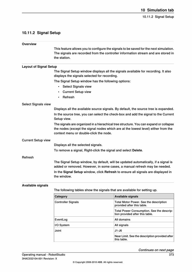
10.11.2 Signal Setup
OverviewThis feature allows you to configure the signals to be saved for the next simulation.The signals are recorded from the controller information stream and are stored inthe station.
Layout of Signal SetupThe Signal Setup window displays all the signals available for recording. It alsodisplays the signals selected for recording.The Signal Setup window has the following options:
• Select Signals view• Current Setup view• Refresh
Select Signals viewDisplays all the available source signals. By default, the source tree is expanded.In the source tree, you can select the check-box and add the signal to the CurrentSetup view.The signals are organized in a hierachical tree structure. You can expand or collapsethe nodes (except the signal nodes which are at the lowest level) either from thecontext menu or double-click the node.
Current Setup viewDisplays all the selected signals.To remove a signal, Right-click the signal and select Delete.
RefreshThe Signal Setup window, by default, will be updated automatically, if a signal isadded or removed. However, in some cases, a manual refresh may be needed.In the Signal Setup window, click Refresh to ensure all signals are displayed inthe window.
Available signalsThe following tables show the signals that are available for setting up.
Available signalsCategory
Total Motor Power. See the descriptionprovided after this table.
Controller Signals
Total Power Consumption. See the descrip-tion provided after this table.
All domainsEventLog
All signalsI/O System
J1-J6Joint
Near Limit. See the description provided afterthis table.
Continues on next pageOperating manual - RobotStudio 3733HAC032104-001 Revision: X
© Copyright 2008-2018 ABB. All rights reserved.
10 Simulation tab10.11.2 Signal Setup
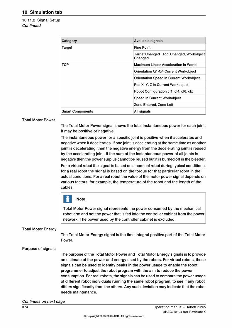
Available signalsCategory
Fine PointTarget
Target Changed , Tool Changed, WorkobjectChanged
Maximum Linear Acceleration in WorldTCP
Orientation Q1-Q4 Current Workobject
Orientation Speed in Current Workobject
Pos X, Y, Z in Current Workobject
Robot Configuration cf1, cf4, cf6, cfx
Speed in Current Workobject
Zone Entered, Zone Left
All signalsSmart Components
Total Motor PowerThe Total Motor Power signal shows the total instantaneous power for each joint.It may be positive or negative.The instantaneous power for a specific joint is positive when it accelerates andnegative when it decelerates. If one joint is accelerating at the same time as anotherjoint is decelerating, then the negative energy from the decelerating joint is reusedby the accelerating joint. If the sum of the instantaneous power of all joints isnegative then the power surplus cannot be reused but it is burned off in the bleeder.For a virtual robot the signal is based on a nominal robot during typical conditions,for a real robot the signal is based on the torque for that particular robot in theactual conditions. For a real robot the value of the motor power signal depends onvarious factors, for example, the temperature of the robot and the length of thecables.
Note
Total Motor Power signal represents the power consumed by the mechanicalrobot arm and not the power that is fed into the controller cabinet from the powernetwork. The power used by the controller cabinet is excluded.
Total Motor EnergyThe Total Motor Energy signal is the time integral positive part of the Total MotorPower.
Purpose of signalsThe purpose of the Total Motor Power and Total Motor Energy signals is to providean estimate of the power and energy used by the robots. For virtual robots, thesesignals can be used to identify peaks in the power usage to enable the robotprogrammer to adjust the robot program with the aim to reduce the powerconsumption. For real robots, the signals can be used to compare the power usageof different robot individuals running the same robot program, to see if any robotdiffers significantly from the others. Any such deviation may indicate that the robotneeds maintenance.
Continues on next page374 Operating manual - RobotStudio
3HAC032104-001 Revision: X© Copyright 2008-2018 ABB. All rights reserved.
10 Simulation tab10.11.2 Signal SetupContinued
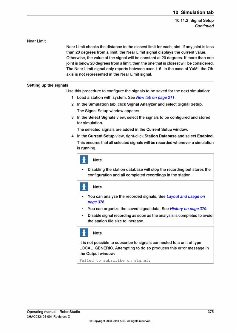
Near LimitNear Limit checks the distance to the closest limit for each joint. If any joint is lessthan 20 degrees from a limit, the Near Limit signal displays the current value.Otherwise, the value of the signal will be constant at 20 degrees. If more than onejoint is below 20 degrees from a limit, then the one that is closest will be considered.The Near Limit signal only reports between axes 1-6. In the case of YuMi, the 7thaxis is not represented in the Near Limit signal.
Setting up the signalsUse this procedure to configure the signals to be saved for the next simulation:
1 Load a station with system. See New tab on page 211 .2 In the Simulation tab, click Signal Analyzer and select Signal Setup.
The Signal Setup window appears.3 In the Select Signals view, select the signals to be configured and stored
for simulation.The selected signals are added in the Current Setup window.
4 In the Current Setup view, right-click Station Database and select Enabled.This ensures that all selected signals will be recorded whenever a simulationis running.
Note
• Disabling the station database will stop the recording but stores theconfiguration and all completed recordings in the station.
Note
• You can analyze the recorded signals. See Layout and usage onpage 376.
• You can organize the saved signal data. See History on page 379.• Disable signal recording as soon as the analysis is completed to avoid
the station file size to increase.
Note
It is not possible to subscribe to signals connected to a unit of typeLOCAL_GENERIC. Attempting to do so produces this error message inthe Output window:Failed to subscribe on signal:
Operating manual - RobotStudio 3753HAC032104-001 Revision: X
© Copyright 2008-2018 ABB. All rights reserved.
10 Simulation tab10.11.2 Signal Setup
Continued

10.11.3 Layout and usage
Layout of Signal AnalyzerThe following figure shows the layout of the Signal Analyzer
en1100000034
Displays a toolbar with options to configure and to work withthe Signal Analyzer.
Toolbar1
Displays a colored bar representing a segment where the signalis set.
Digital signal values2
Displays analog and numeric signal values.Analog signal values3
Displays discrete events, such as EventLog messages.Events4
Displays information about all recorded signals for the currentdata session.
Signals table5
ToolbarThe toolbar displays the following options:
DescriptionOption
For selecting the signal recording to be displayed. These sig-nals are also available in Signal History. See History onpage 379.
Drop-down list
For moving the time forward and backward.Timer slider
For zooming in / out the time axis.Zoom in/out buttons
For enabling data to be shown live, that is, as recorded duringa simulation.
Live data button
For displaying the crosshairs following the mouse.Crosshair
For enabling / disabling vertical axis autoscaling.Auto scale button
For displaying the line markers for each sample in the analog/ numeric graph.
Line marker button
For exporting the data to a file.Save buttonThe data can be saved in Microsoft Excel 2007 format and tabdelimited text format.
Continues on next page376 Operating manual - RobotStudio
3HAC032104-001 Revision: X© Copyright 2008-2018 ABB. All rights reserved.
10 Simulation tab10.11.3 Layout and usage

Digital signal valuesIt displays one row per digital signal, showing the signal state over time. A solidcolored bar indicates the signal is set (value=1), otherwise the signal is cleared(value=0). The signal name is displayed to the left.Move the mouse over the colored bars to view additional information like the timestamps when the signal was set and reset.
Analog signal valuesIt displays a 2D line graph for each analog signal. It consists of the following:
• Left-side vertical axis• Horizontal axis displaying time in seconds• Plot area displaying the signal graphs• Optional right-side vertical axis.
You can configure the individual signals to use the right-side vertical axis scalefrom the signals table at the bottom of the window. This axis is hidden by default.The following actions can be performed in this segment:
• Scale the vertical axes: If you select the autoscale button in the toolbar, thenthe vertical axes will automatically scale to ensure that the line graphs arevisible. You can modify the vertical scale using the mouse if the cursor isover the axis value area. This automatically deselects the autoscale button.
• Pan and Zoom time axis: If the cursor is over the central, main area of theplot, then you can scale, pan, and zoom the time axis using the mouse.
EventsIt displays one row per selected event category. Each event is indicated with adiamond shaped icon. Click this icon to display a popup with more informationabout the event.
Signals tableDisplays information about each recorded signal. This enables you to configuresettings for each signal such as color, visibility, whether to use left or right verticalaxis and so on.
Using the Signal AnalyzerUse this procedure to analyze the recorded signal data:
1 Set up the signals to be analyzed. See Setting up the signals on page 375.2 Record signal data by running a simulation. See Setting up the signals on
page 375.3 In the Simulation tab, click Signal Analyzer.
Continues on next pageOperating manual - RobotStudio 3773HAC032104-001 Revision: X
© Copyright 2008-2018 ABB. All rights reserved.
10 Simulation tab10.11.3 Layout and usage
Continued

The Signal Analyzer window appears.
Note
• If the station does not contain any saved signal data, you will thenhave to setup the signals to analyze and record by running asimulation. See Signal Setup on page 373.
• You can organize the saved signal data. See History on page 379.• The sample interval of the Signal Analyzer is 24 ms, hence signal
changes within this interval will not be captured.
378 Operating manual - RobotStudio3HAC032104-001 Revision: X
© Copyright 2008-2018 ABB. All rights reserved.
10 Simulation tab10.11.3 Layout and usageContinued

10.11.4 History
OverviewThis feature displays and helps in organizing saved signal recordings of the currentRobotStudio station.
Layout of Signal HistoryYou can do the following from the Signal History window:
• Click the column header to sort the history in ascending or descending order.• Click the drop-down to group the history as View By Today or View by Order.
Organizing the Signal HistoryUse this procedure to organize the signal history:
1 Create a saved signal data in the station. See Setting up the signals onpage 375.
2 In the Simulation tab, click Signal Analyzer and select History.The Signal History window with all the stored signal history elements aredisplayed.
Note
The signal history elements in the Signal History window is updatedautomatically whenever the signals are setup and the simulation is started/ stopped.
3 In the Signal History window, right-click a history element and select:• Analyze: To open the Signal Analyzer window.• Export: To save selected history elements to a file.
Note
The maximum number of signals that can be exported to Excel islimited to 26.
• Delete: To remove the selected signal recording permanently.• Rename: To rename the signal recording.
Note
Disable signal recording as soon as the analysis is completed to avoid the stationfile size to increase.
Operating manual - RobotStudio 3793HAC032104-001 Revision: X
© Copyright 2008-2018 ABB. All rights reserved.
10 Simulation tab10.11.4 History
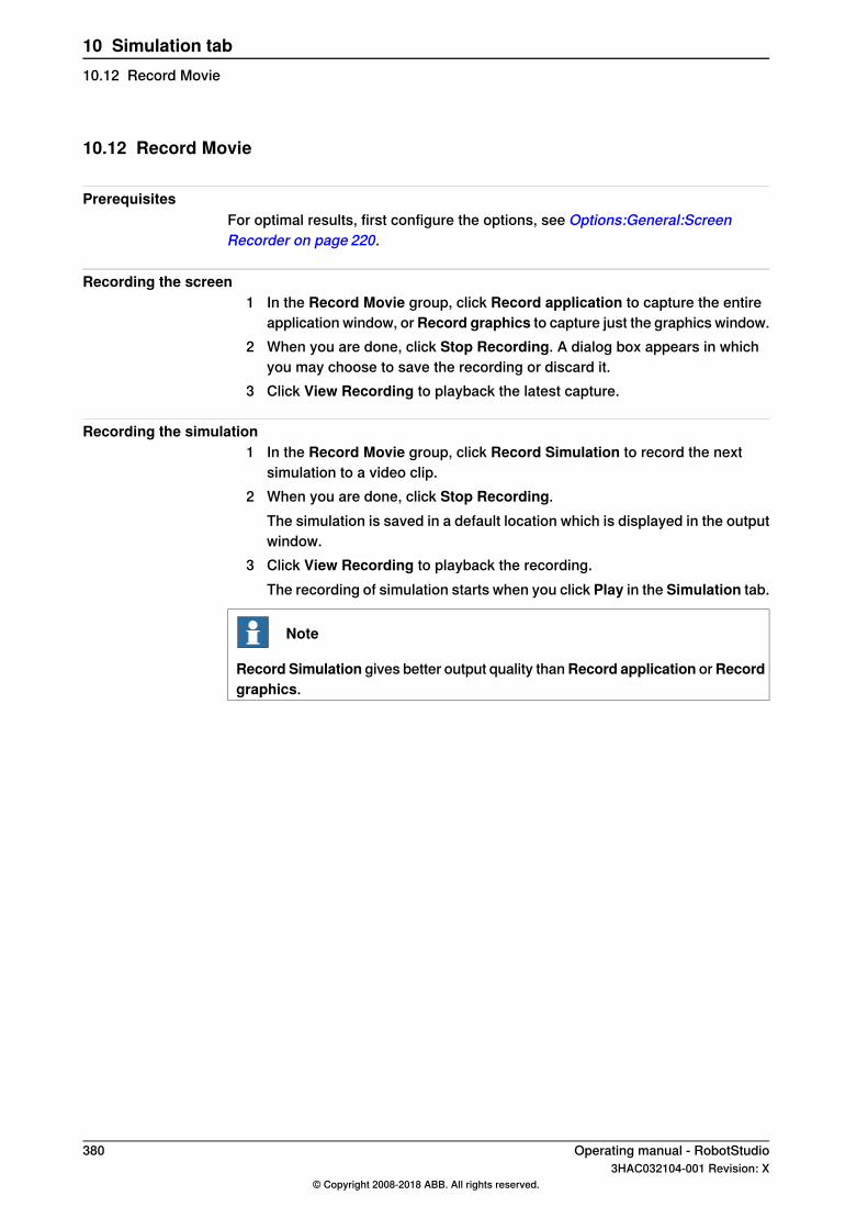
10.12 Record Movie
PrerequisitesFor optimal results, first configure the options, see Options:General:ScreenRecorder on page 220.
Recording the screen1 In the Record Movie group, click Record application to capture the entire
application window, orRecord graphics to capture just the graphics window.2 When you are done, click Stop Recording. A dialog box appears in which
you may choose to save the recording or discard it.3 Click View Recording to playback the latest capture.
Recording the simulation1 In the Record Movie group, click Record Simulation to record the next
simulation to a video clip.2 When you are done, click Stop Recording.
The simulation is saved in a default location which is displayed in the outputwindow.
3 Click View Recording to playback the recording.The recording of simulation starts when you click Play in the Simulation tab.
Note
Record Simulation gives better output quality thanRecord application orRecordgraphics.
380 Operating manual - RobotStudio3HAC032104-001 Revision: X
© Copyright 2008-2018 ABB. All rights reserved.
10 Simulation tab10.12 Record Movie
10.13 Conveyor Tracking Mechanism
10.13.1 Conveyor Tracking
OverviewConveyor tracking is the function where the robot follows a workobject mountedon a moving conveyor. This section describes how to create a conveyor, add andremove objects to and from the conveyor, create targets during tracking, andsimulate conveyor.RobotStudio does not support tracking of circular conveyors. Only linear conveyorsare supported. For more information, see the Application manual - Conveyortracking.
Conveyor tracking mechanismThis procedure describes the workflow for making a conveyor tracking systemwork in RobotStudio.
1 Create a conveyor mechanism. See Create Conveyor on page 344.2 Setup the conveyor. See Adding objects to the conveyor on page 232.
For information on setting up a conveyor tracking station with two robotsworking on the same conveyor, see Setting Conveyor tracking on page 83.
3 Jog the conveyor as well as the robot and teach some targets. SeeMechanism Joint Jog on page 518.
4 Simulate the conveyor. See Conveyor Simulation on page 382.5 Remove objects from conveyor. See Removing objects from conveyor on
page 232.
Operating manual - RobotStudio 3813HAC032104-001 Revision: X
© Copyright 2008-2018 ABB. All rights reserved.
10 Simulation tab10.13.1 Conveyor Tracking
10.13.2 Conveyor Simulation
Running a conveyor simulation1 Create Action Instructions. See Action Instruction on page 262.
Create the following five action instructions along with Move instructions:ConfL\Off,ActUnit CNV1,WaitWObj Workobject_1,
DropWObjWorkobject_1 and DeactUnit CNV1.The following program is an example showing how the sequence ofinstructions appears:ConfL\Off;
MoveJ p0, vmax , fine, tool1;
ActUnit CNV1;
WaitWObj wobjcnv1;
MoveL p10, v1000, z1, tool1\Wobj :=wobjcnv1;
MoveL p20, v1000, z1, tool1\Wobj :=wobjcnv1;
MoveL p30, v500, z20, tool1\Wobj :=wobjcnv1;
MoveL p40, v500, fine, tool1;
DropWObj wobjcnv1;
MoveL p0, v500, fine;
DeactUnit CNV1;
Note
If an error occurs while executing the program, the controller reaches Guardstate. In this state, RobotStudio cannot execute the program during thenext simulation. To recover from this state, open the Control Panel andswitch to Manual Mode and then to Auto Mode.For more information, see Application manual - Conveyor tracking.
2 Synchronize to VC. See Synchronize to RAPID on page 453.3 Set up the simulation. See Simulation Setup on page 357.4 In the Layout browser, right-click the conveyor mechanism and selectMotion.5 In the Speed box, set the speed during simulation.
Select the Start and Stop buttons to start and stop the conveyor duringsimulation.
6 Click Apply.7 Click Play to run the simulation.
A RAPID program with Conveyor Tracking must be run with the Play buttonin the Simulation tab.
Continues on next page382 Operating manual - RobotStudio
3HAC032104-001 Revision: X© Copyright 2008-2018 ABB. All rights reserved.
10 Simulation tab10.13.2 Conveyor Simulation
Note
The conveyor speed and direction can be changed while running the simulation.To jump the conveyor back to the start position, clickReset. This button remainsenabled as long as the station has at least one conveyor.
Operating manual - RobotStudio 3833HAC032104-001 Revision: X
© Copyright 2008-2018 ABB. All rights reserved.
10 Simulation tab10.13.2 Conveyor Simulation
Continued

This page is intentionally left blank
11 Controller tab11.1 Real and virtual controllers
OverviewThe Controller tab contains the controls for managing the real controller and alsothe controls for synchronization, configuration and tasks assigned to the virtualcontroller.RobotStudio allows you to work with an off-line controller, which is a virtual IRC5controller running locally on your PC. This offline controller is also referred to asthe virtual controller (VC). RobotStudio also allows you to work with the real physicalIRC5 controller, which is simply referred to as the real controller.The features on the Controller tab can be categorized as follows:
• Features for both virtual and real controllers• Features for real controllers• Features for virtual controllers
For more information on working with a real controller, see Working online onpage 153.
Operating manual - RobotStudio 3853HAC032104-001 Revision: X
© Copyright 2008-2018 ABB. All rights reserved.
11 Controller tab11.1 Real and virtual controllers
11.2 Features for both virtual and real controllers
11.2.1 Add Controller
Adding and connecting to a controllerYou can connect to real or virtual controller using the Add Controller button.To connect to a real controller, on the Controller tab click the arrow next to theAdd Controller icon, and then click one of the following commands as per yourrequirement:
• One Click Connect - For connecting to the service port of the controller• Add Controller - For adding available controllers to the network
Note
For connecting RobotStudio to a real controller over the Ethernet (LAN), thecontroller system must have the RobotWare option PC-interface. This option isnot required when connecting through the service port.
To start and connect to a virtual controller, on the Controller tab click the arrownext to the Add Controller icon, and then click Start Virtual Controller.
One Click ConnectThe One Click Connect feature allows connecting to a robot controller, that isconnected to the service port, in a single step. You need to do the following beforeusing this feature:
• Connect the computer to the controller service port.• Ensure that the network settings on the PC is correct. DHCP should either
be enabled or the IP address should have a specific value. For moreinformation on network settings, see Network settings on page 157.
On the Controller tab, click the arrow next to the Add Controller icon, and thenclick One Click Connect.
Add Controller1 In the Controller tab, click Add Controller to bring up a dialog box in which
all available controllers are listed.2 If the controller is not found in the list, type its IP address in the IP Address
box, and then click Refresh.3 Select the controller in the list and click OK.
Add Remote Controller1 In the Controller tab, click Add Controller to bring up a dialog box in which
all available controllers are listed.2 If the controller is not found in the list, type its IP address in the Remote
Controller box, and then click Add.3 Select the controller in the list and click OK.
Continues on next page386 Operating manual - RobotStudio
3HAC032104-001 Revision: X© Copyright 2008-2018 ABB. All rights reserved.
11 Controller tab11.2.1 Add Controller
Start Virtual ControllerThe Start Virtual Controller command allows you to start and stop a virtualcontroller, using a given system path and without needing a station.
Tip
You can use the Start Virtual Controller command when you require a virtualcontroller as emulator while developing PC SDK or RobotWare add-ins. You canalso use this command when you need to use the Configuration editor or theRAPID editor without requiring a station.
Clicking Start Virtual Controller under Add Controller opens the Start VirtualController dialog box. In this dialog box, specify the following:
1 In the System Pool drop-down list specify the location and folder of your PCwhere the required virtual controller systems are stored.To add a folder to this list, click Add and then browse to and select the folderto be added. To remove a folder from the list, click Remove.
2 The Systems Found table lists the virtual controller systems found in theselected system folder. Click a system to select it for starting.
3 Select the required check boxes:• Reset system, to start the VC with the current system and the default
settings• Local login• Handle Write Access automatically
Note
A virtual controller system that has been modified using theModify Systemfunction of the System Builder must be restarted with the Reset Systemoption for the changes to take effect.
Low Bandwidth modeThe low bandwidth mode is useful when connecting RobotStudio to a controllerover a network connection with limited bandwidth. It reduces controllercommunication to a fraction of the regular connection mode.
Note
RobotWare version installed in the controller and in the connecting PC must besame.
You can select the low bandwidth mode while connecting to the controller throughthe Add controller dialog.
Continues on next pageOperating manual - RobotStudio 3873HAC032104-001 Revision: X
© Copyright 2008-2018 ABB. All rights reserved.
11 Controller tab11.2.1 Add Controller
Continued
LimitationsIn low bandwidth mode;
• the signal analyzer gets disabled.• system requires manual refresh to update the I/O Viewer, RAPID Watch
window, RAPID Program Pointer, Online Monitor and FlexPendant Viewerin RobotStudio with the current controller status, hence manual buttons areadded to initiate the refresh.
• semantic check in the RAPID editor will be restricted.
388 Operating manual - RobotStudio3HAC032104-001 Revision: X
© Copyright 2008-2018 ABB. All rights reserved.
11 Controller tab11.2.1 Add ControllerContinued

11.2.2 Events
OverviewYou can view events in the Event log. The severity of each event is indicated byits background color; blue for information, yellow for warning and red for an errorwhich needs to be corrected to proceed.On theController tab in theController Tools group, click Events to view the Eventlog.
Event logYou can perform the following operations on the Event log.
DescriptionsAvailable opera-tions
Click any event to see a brief description about the event.View
The Auto Update check box is selected by default, so that new eventsappear in the list as they occur.
Automatic update
Clear the check box to disable automatic update. Selecting it again,fetches and displays the events missed while it was cleared.
You can filter the event log list based on the category of the event orbased on any text in its displayed details.
Filter
To filter the list based on any required text, specify it in the Text box.Use theCategory drop-down list to filter based on the events categories.The event categories are: Common, Operational, System, Hardware,Program, Motion, I/O & Communication, User, Internal, Process, Config-uration and RAPID.
Click Save, to save the event records of the selected event categoriesto log files on the computer.
Save
Select the Log to file check box to enable all events currently in theCommon Event Log to be saved to a log file.
Log to file
The log file will be updated with all new events as they occur.
Operating manual - RobotStudio 3893HAC032104-001 Revision: X
© Copyright 2008-2018 ABB. All rights reserved.
11 Controller tab11.2.2 Events

11.2.3 Inputs/Outputs
OverviewYou can view and set input and output signals in the I/O System window.To open this window, on the Controller tab, in the Controller Tools group, clickInputs/Outputs.
Note
For details on local I/O and its features, refer Application manual Local I/O.
I/O System windowThe following details of I/O signals are available in the I/O System window:
DescriptionColumn
Shows the name of the signal, name is set by the device's configurationand cannot be changed from the I/O system.
Name
Shows the type of signal using the abbreviations listed in the followingtable.
DescriptionAbbreviation
Digital input signal.DI
Digital output signal.DO
Analog input signal.AI
Analog output signal.AO
Group of signals, working as one input signal.GI
Group of signals, working as one output signal.GO
Type
The signal type is set by the device's configuration and cannot bechanged from the I/O system.
Shows the value of the signal, double-click the signal row to edit thevalue.
Value
Shows the minimum value of a signal.Min Value
Shows the maximum value of a signal.Max Value
Shows the simulation status of a signal. When a signal is simulated, youcan specify a value that overrides the actual signal value.
Logical State
You can change the logical state of a signal from the I/O system byturning the simulation ON/Off.
Shows device to which the signal belongs.UnitThis is set by the device's configuration and cannot be changed fromthe I/O system.You can view this field in RobotWare 6.0 or before.
Shows the industrial network to which the signal belongs.BusThis is set by the industrial network configuration and cannot be changedfrom the I/O system.You can view this field in RobotWare 6.0 or before.
Shows whether the I/O device is simulated on the industrial network itis connected to.
Simulated
Continues on next page390 Operating manual - RobotStudio
3HAC032104-001 Revision: X© Copyright 2008-2018 ABB. All rights reserved.
11 Controller tab11.2.3 Inputs/Outputs
DescriptionColumn
Shows the industrial network to which this I/O device is physically con-nected.
Network
Shows the logical representation of the real I/O device.Device
Shows the bit(s) to which the I/O signal is mapped in the I/O memorymap of the assigned I/O device.
Device Mapping
Shows a free-text categorization to an I/O signal.Category
Shows the Signal Identification Label as defined in the I/O Configurationdatabase.
Label
It is possible to sort signals according to the signal properties. In the I/O Systemwindow, click the particular field to sort signals according to the field. If you pressthe SHIFT key and click multiple column headers then the columns will be sortedby the order clicked.
I/O System window viewUse the following parameters to set the view of the I/O system window.
• Name and Label: Use the free-text edit boxes above these columns. Theresulting view will show signals that contain the entered text string in therespective field.
• Simulated: Select this check box to view simulated signals only• Unit, Bus, and Category: Use the drop-down list boxes above each column
to select the required option for the respective parameter. The resulting viewwill show only those signals that have the selected option.
• Clear filter: Click this button to reset the view, and show all signals again.
I/O Signal Data EditorThe I/O signal data editor is a table like editor used for editing signals. In this editoryou can add, delete and sort signals. This table can be exported to Microsoft Excelfor editing and for further importing back to RobotStudio.Follow these steps to open an I/O signal data editor.
1 In the RAPID tab open a backup file.2 In the Files browser, select the SYSPAR folder of the backup file and then
right-click the EIO.cfg file.3 In the context menu, click I/O Signal Data Editor option, the I/O signal data
editor opens.
Operating manual - RobotStudio 3913HAC032104-001 Revision: X
© Copyright 2008-2018 ABB. All rights reserved.
11 Controller tab11.2.3 Inputs/Outputs
Continued

11.2.4 ScreenMaker
OverviewScreenMaker is a tool in RobotStudio for creating customized FlexPendant userinterfaces without the need to learn Visual Studio development environment and.NET programming.For more information on ScreenMaker, see ScreenMaker tab on page 549.
Prerequisites
Note
In RobotStudio 6.0, ScreenMaker is only available for the 32-bit edition and istherefore disabled in the 64-bit edition.
To use ScreenMaker, you need to fulfill the following requirements:• RobotStudio with Premium license.• The IRC5 controller(s) require the FlexPendant Interface option in RobotWare
to run ScreenMaker applications.• Install Microsoft .NET Compact Framework 2.0. Download it from ht-
tp://www.microsoft.com/download• Install FlexPendant SDK with the same version as the RobotWare on the
target controller. Download it from http://developercenter.robotstudio.com/For more information on the system requirements, hardware requirements, andthe supported Operating Systems, see RobotStudio Release Notes.
Testing on Virtual/Real controller
Best practicesYou must test the screenmaker application on the virtual controller against a virtualFlexPendant. Having LAN capabilities through the PC Interface option would behelpful.
Testing and Deploying to a Virtual ControllerClick Deploy in the ScreenMaker to deploy to the connected controller in theapplication. In a virtual controller, the application is deployed directly, which canbe used for viewing your application quickly on virtual FlexPendant before deployingthe same to the real controller.
Testing and Deploying to a Real ControllerClickDeploy in ScreenMaker to deploy to the connected controller in the application.PC interface option is needed to deploy an application over LAN to real controller.The application can also be deployed directly through service port.
Launching ScreenMakerYou can launch ScreenMaker either from the Controller tab.
1 In the Controller tab, click the arrow next to the FlexPendant icon.2 Click ScreenMaker.
Continues on next page392 Operating manual - RobotStudio
3HAC032104-001 Revision: X© Copyright 2008-2018 ABB. All rights reserved.
11 Controller tab11.2.4 ScreenMaker

ScreenMaker is launched as a new tab.The connection to all connected virtual and real controllers can beestablished.
Note
For more information, see Managing projects on page 557.
Operating manual - RobotStudio 3933HAC032104-001 Revision: X
© Copyright 2008-2018 ABB. All rights reserved.
11 Controller tab11.2.4 ScreenMaker
Continued
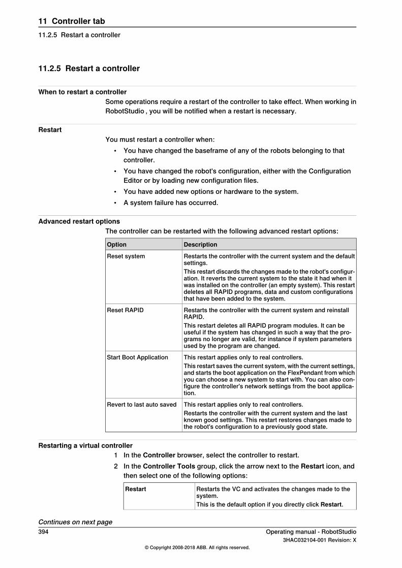
11.2.5 Restart a controller
When to restart a controllerSome operations require a restart of the controller to take effect. When working inRobotStudio , you will be notified when a restart is necessary.
RestartYou must restart a controller when:
• You have changed the baseframe of any of the robots belonging to thatcontroller.
• You have changed the robot's configuration, either with the ConfigurationEditor or by loading new configuration files.
• You have added new options or hardware to the system.• A system failure has occurred.
Advanced restart optionsThe controller can be restarted with the following advanced restart options:
DescriptionOption
Restarts the controller with the current system and the defaultsettings.
Reset system
This restart discards the changes made to the robot's configur-ation. It reverts the current system to the state it had when itwas installed on the controller (an empty system). This restartdeletes all RAPID programs, data and custom configurationsthat have been added to the system.
Restarts the controller with the current system and reinstallRAPID.
Reset RAPID
This restart deletes all RAPID program modules. It can beuseful if the system has changed in such a way that the pro-grams no longer are valid, for instance if system parametersused by the program are changed.
This restart applies only to real controllers.Start Boot ApplicationThis restart saves the current system, with the current settings,and starts the boot application on the FlexPendant from whichyou can choose a new system to start with. You can also con-figure the controller's network settings from the boot applica-tion.
This restart applies only to real controllers.Revert to last auto savedRestarts the controller with the current system and the lastknown good settings. This restart restores changes made tothe robot's configuration to a previously good state.
Restarting a virtual controller1 In the Controller browser, select the controller to restart.2 In the Controller Tools group, click the arrow next to the Restart icon, and
then select one of the following options:
Restarts the VC and activates the changes made to thesystem.
Restart
This is the default option if you directly click Restart.
Continues on next page394 Operating manual - RobotStudio
3HAC032104-001 Revision: X© Copyright 2008-2018 ABB. All rights reserved.
11 Controller tab11.2.5 Restart a controller
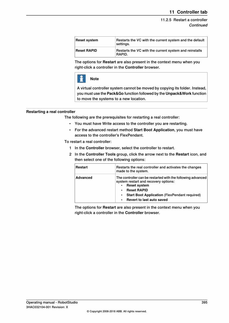
Restarts the VC with the current system and the defaultsettings.
Reset system
Restarts the VC with the current system and reinstallsRAPID.
Reset RAPID
The options for Restart are also present in the context menu when youright-click a controller in the Controller browser.
Note
A virtual controller system cannot be moved by copying its folder. Instead,you must use thePack&Go function followed by theUnpack&Work functionto move the systems to a new location.
Restarting a real controllerThe following are the prerequisites for restarting a real controller:
• You must have Write access to the controller you are restarting.• For the advanced restart method Start Boot Application, you must have
access to the controller's FlexPendant.To restart a real controller:
1 In the Controller browser, select the controller to restart.2 In the Controller Tools group, click the arrow next to the Restart icon, and
then select one of the following options:
Restarts the real controller and activates the changesmade to the system.
Restart
The controller can be restarted with the following advancedsystem restart and recovery options:
• Reset system• Reset RAPID• Start Boot Application (FlexPendant required)• Revert to last auto saved
Advanced
The options for Restart are also present in the context menu when youright-click a controller in the Controller browser.
Operating manual - RobotStudio 3953HAC032104-001 Revision: X
© Copyright 2008-2018 ABB. All rights reserved.
11 Controller tab11.2.5 Restart a controller
Continued
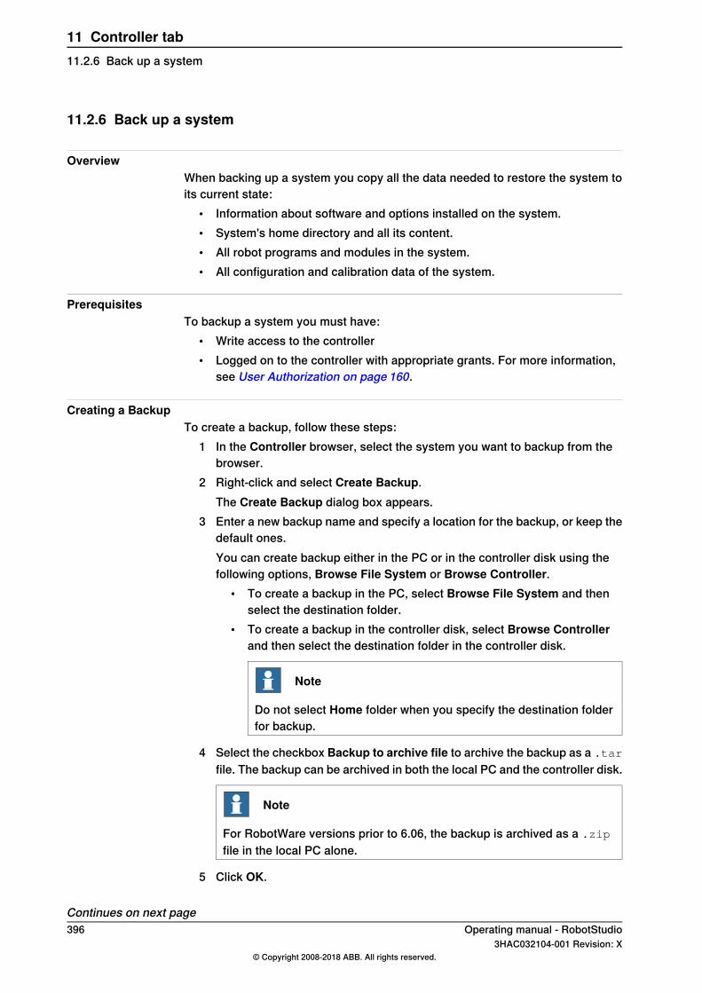
11.2.6 Back up a system
OverviewWhen backing up a system you copy all the data needed to restore the system toits current state:
• Information about software and options installed on the system.• System's home directory and all its content.• All robot programs and modules in the system.• All configuration and calibration data of the system.
PrerequisitesTo backup a system you must have:
• Write access to the controller• Logged on to the controller with appropriate grants. For more information,
see User Authorization on page 160.
Creating a BackupTo create a backup, follow these steps:
1 In the Controller browser, select the system you want to backup from thebrowser.
2 Right-click and select Create Backup.The Create Backup dialog box appears.
3 Enter a new backup name and specify a location for the backup, or keep thedefault ones.You can create backup either in the PC or in the controller disk using thefollowing options, Browse File System or Browse Controller.
• To create a backup in the PC, select Browse File System and thenselect the destination folder.
• To create a backup in the controller disk, select Browse Controllerand then select the destination folder in the controller disk.
Note
Do not select Home folder when you specify the destination folderfor backup.
4 Select the checkbox Backup to archive file to archive the backup as a .tarfile. The backup can be archived in both the local PC and the controller disk.
Note
For RobotWare versions prior to 6.06, the backup is archived as a .zip
file in the local PC alone.
5 Click OK.
Continues on next page396 Operating manual - RobotStudio
3HAC032104-001 Revision: X© Copyright 2008-2018 ABB. All rights reserved.
11 Controller tab11.2.6 Back up a system
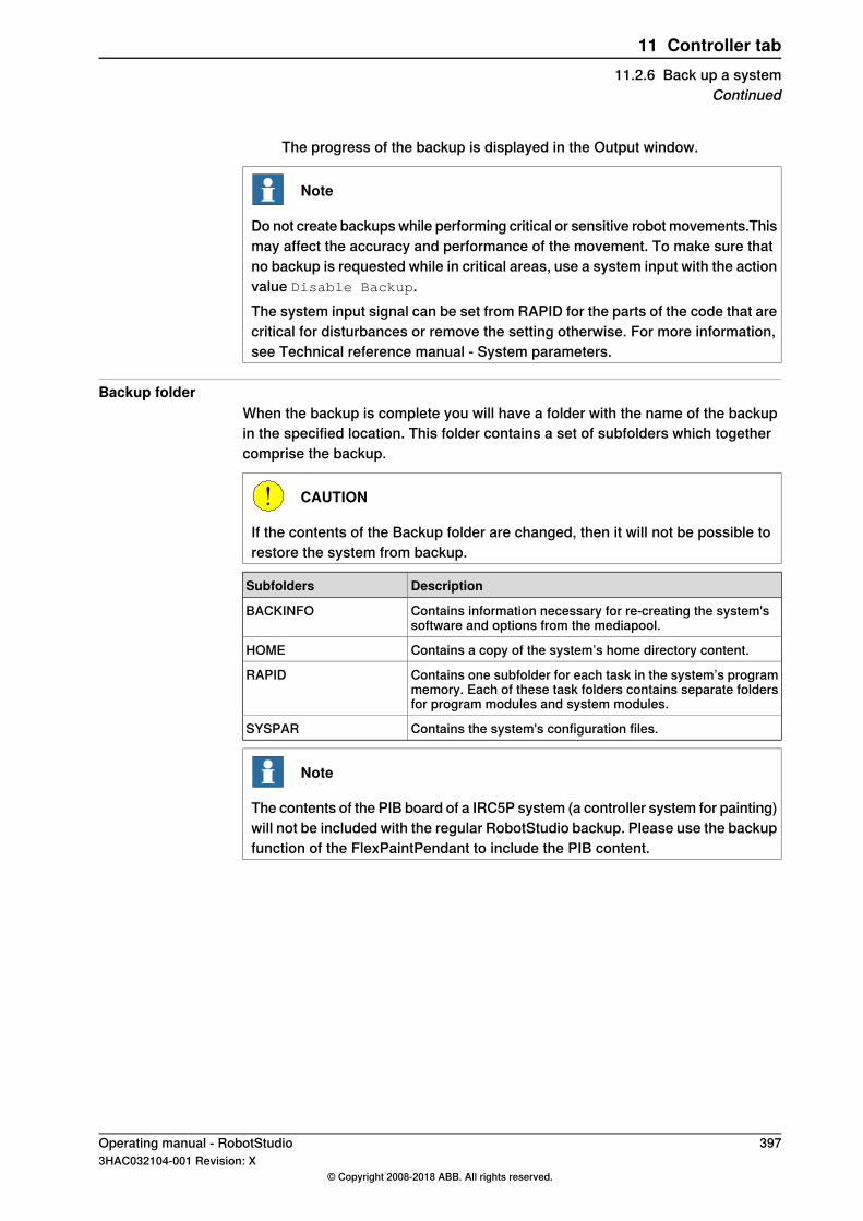
The progress of the backup is displayed in the Output window.
Note
Do not create backups while performing critical or sensitive robot movements.Thismay affect the accuracy and performance of the movement. To make sure thatno backup is requested while in critical areas, use a system input with the actionvalue Disable Backup.The system input signal can be set from RAPID for the parts of the code that arecritical for disturbances or remove the setting otherwise. For more information,see Technical reference manual - System parameters.
Backup folderWhen the backup is complete you will have a folder with the name of the backupin the specified location. This folder contains a set of subfolders which togethercomprise the backup.
CAUTION
If the contents of the Backup folder are changed, then it will not be possible torestore the system from backup.
DescriptionSubfolders
Contains information necessary for re-creating the system'ssoftware and options from the mediapool.
BACKINFO
Contains a copy of the system’s home directory content.HOME
Contains one subfolder for each task in the system’s programmemory. Each of these task folders contains separate foldersfor program modules and system modules.
RAPID
Contains the system's configuration files.SYSPAR
Note
The contents of the PIB board of a IRC5P system (a controller system for painting)will not be included with the regular RobotStudio backup. Please use the backupfunction of the FlexPaintPendant to include the PIB content.
Operating manual - RobotStudio 3973HAC032104-001 Revision: X
© Copyright 2008-2018 ABB. All rights reserved.
11 Controller tab11.2.6 Back up a system
Continued

11.2.7 Restore a system
OverviewWhen restoring a system from backup, the current system gets the same contentas when the backup was performed. Restoring a system replaces the followingcontents in the current system with the content from the backup:
• All RAPID programs and modules in the system.• All configuration and calibration data of the system.
Note
The system's home directory and all its content are copied from the backup tothe current system.
PrerequisitesTo restore a system you must have:
• Write access to the controller.• Logged on to the controller with appropriate grants. For more information,
see User Authorization on page 160.
Restoring a system
Note
Before proceeding, make sure that the system from the backup is compatiblewith the controller you are restoring.
To restore a system, follow these steps:1 In the Controller browser, select the system you want to restore.2 Click Backup and select Restore Backup.
The Restore from Backup dialog box appears.
Note
Select the Include Controller Settings check box to restore the UASsettings, time settings and IP address, and select Include Safety Settingscheck box to include the safety settings.
3 In the Restore from Backup dialog box, browse to the source folder eitherin the PC or in the controller disk and then select the backup to restore thesystem.
Note
If the backup file being restored is a .zip file, then it can only be restoredfrom the local PC.
4 Click OK.Continues on next page398 Operating manual - RobotStudio
3HAC032104-001 Revision: X© Copyright 2008-2018 ABB. All rights reserved.
11 Controller tab11.2.7 Restore a system
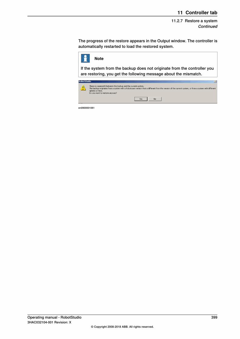
The progress of the restore appears in the Output window. The controller isautomatically restarted to load the restored system.
Note
If the system from the backup does not originate from the controller youare restoring, you get the following message about the mismatch.
en0900001061
Operating manual - RobotStudio 3993HAC032104-001 Revision: X
© Copyright 2008-2018 ABB. All rights reserved.
11 Controller tab11.2.7 Restore a system
Continued
11.2.8 System Builder
Functions of the System BuilderFor procedures using the various functions of the System Builder, see AboutSystem Builder on page 162.
400 Operating manual - RobotStudio3HAC032104-001 Revision: X
© Copyright 2008-2018 ABB. All rights reserved.
11 Controller tab11.2.8 System Builder
11.2.9 Installation Manager
Functions of Installation ManagerFor procedures using various functions of the Installation Manager, see AboutInstallation Manager on page 181.
Operating manual - RobotStudio 4013HAC032104-001 Revision: X
© Copyright 2008-2018 ABB. All rights reserved.
11 Controller tab11.2.9 Installation Manager
11.2.10 Configuration editor
Configuration editorFrom the Configuration Editor you view and edit the system parameters of a specifictopic in a controller. The Instance Editor is a complementary editor with which youedit the details of a type instance (a row in the Configuration Editor's instance list).The Configuration Editor has a direct communication with the controller. This meansthat changes you make are applied to the controller as soon as you complete thecommand.With the Configuration Editor, including the Instance Editor, you can:
• view types, instances, and parameters• edit instances and parameters• copy and paste instances within a topic• add and delete instances
Layout of the Configuration EditorThe Configuration Editor consists of the Type name list and the Instance list.The Type name list displays all available configuration types for the selected topic.The list of types is static. This means you cannot add, delete or rename types.The Instance list displays all system parameters of the type selected in the Typename list. Each row in the list is an instance of the system parameter type. Thecolumns show each specific parameter and its value for each instance of theparameter type.The Configuration editor has the following options:
• Controller• I/O• Communication• Motion• Man-machine communication• Add Signals
Click the header of a column to sort the column. For sorted columns, the sort orderwill be reversed. If you press the SHIFT key and click multiple column headersthen the columns will be sorted by the order clicked.
Add SignalsYou must have write access to the controller to be able to open the add signalwindow.
Defines the type of signal.Type of Signal
Defines the name for one or more signals.Signal Base Name
Defines the device to which the signal belongs.Assigned to Device
Optionally, offers filtering and sorting based on this category.Signal Identification Label
Defines the number of signals to add in a rangeNumber of Signals
Defines the index (number) to start the range with.Start Index
Continues on next page402 Operating manual - RobotStudio
3HAC032104-001 Revision: X© Copyright 2008-2018 ABB. All rights reserved.
11 Controller tab11.2.10 Configuration editor
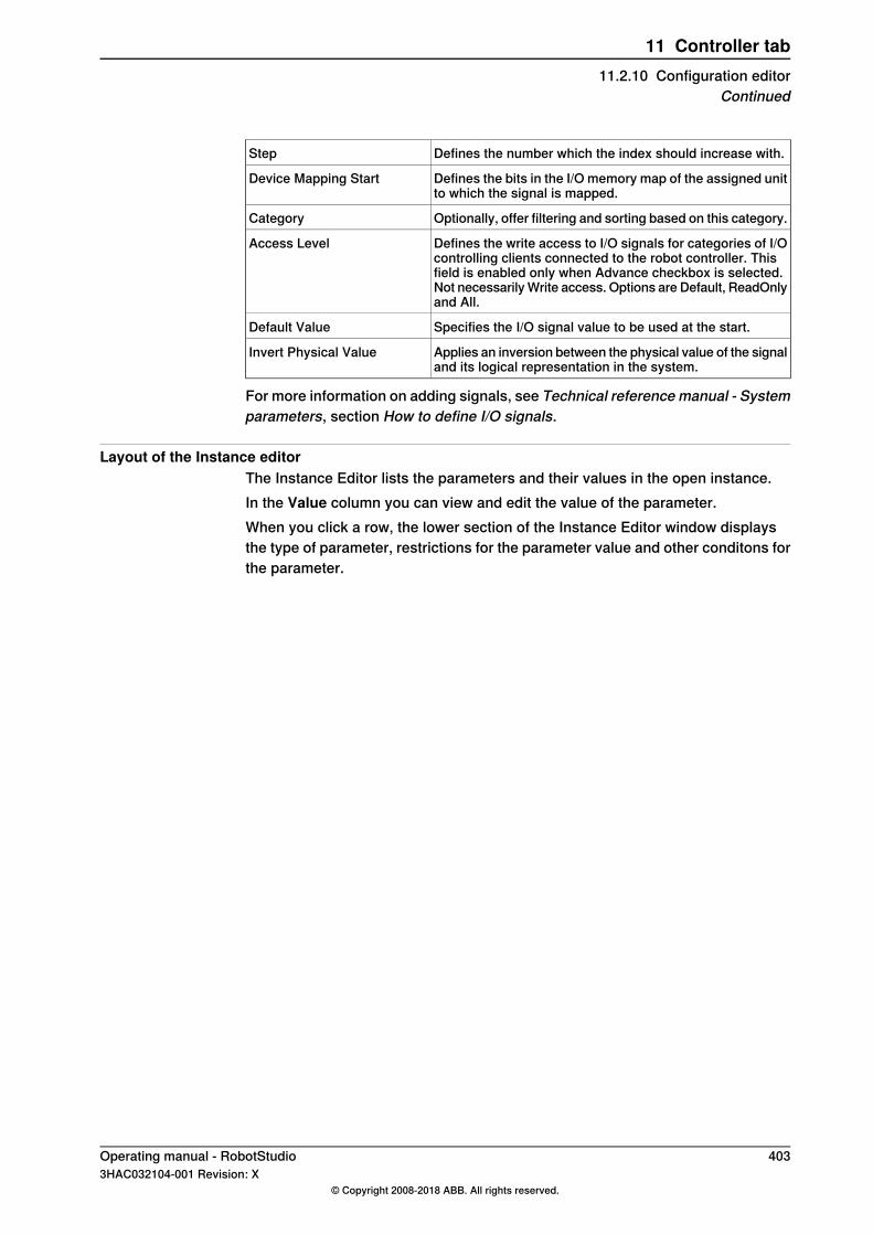
Defines the number which the index should increase with.Step
Defines the bits in the I/O memory map of the assigned unitto which the signal is mapped.
Device Mapping Start
Optionally, offer filtering and sorting based on this category.Category
Defines the write access to I/O signals for categories of I/Ocontrolling clients connected to the robot controller. Thisfield is enabled only when Advance checkbox is selected.Not necessarily Write access. Options are Default, ReadOnlyand All.
Access Level
Specifies the I/O signal value to be used at the start.Default Value
Applies an inversion between the physical value of the signaland its logical representation in the system.
Invert Physical Value
For more information on adding signals, see Technical reference manual - Systemparameters, section How to define I/O signals.
Layout of the Instance editorThe Instance Editor lists the parameters and their values in the open instance.In the Value column you can view and edit the value of the parameter.When you click a row, the lower section of the Instance Editor window displaysthe type of parameter, restrictions for the parameter value and other conditons forthe parameter.
Operating manual - RobotStudio 4033HAC032104-001 Revision: X
© Copyright 2008-2018 ABB. All rights reserved.
11 Controller tab11.2.10 Configuration editor
Continued

11.2.11 Load Parameters
PrerequisiteYou must have write access to the controller.
Loading a configuration fileYou can load a configuration file either from the system or from the controller disk.
1 In the Controller browser, select the system and expand the Configurationnode.
2 To load a configuration file from the system, click Load Parameters to bringup a dialog box.To load a configuration file from the controller disk, click Load Parametersfrom Controller, to bring up a dialog box.
3 In the dialog box, select how you want to combine the parameters in theconfiguration file to load with the existing parameters:
then select...If you want to...
Delete existing parameters before load-ing
replace the entire configuration of thetopic with the one in the configuration file.
Load parameters if no duplicatesadd new parameters from the configura-tion file to the topic, without modifying theexisting ones.
Load parameters and replace duplicatesadd new parameters from the configura-tion file to the topic and update the exist-ing ones with values from the configura-tion file. Parameters that only exist in thecontroller and not in the configuration filewill not be changed at all.
4 Click Open and browse to the configuration file to load. Then click Openagain.
5 In the information box, click OK to confirm that you want to load theparameters from the configuration file.
6 When the loading of the configuration file is finished, close the Select modedialog box.If a restart of the controller is necessary for the new parameters to take effect,you will be notified of this.
404 Operating manual - RobotStudio3HAC032104-001 Revision: X
© Copyright 2008-2018 ABB. All rights reserved.
11 Controller tab11.2.11 Load Parameters
11.2.12 Save Parameters
OverviewThe system parameters of a configuration topic can be saved to a configurationfile, stored on the PC or any of its network drives.The configuration files can then be loaded into a controller. They are thereby usefulas backups, or for transferring configurations from one controller to another.
File-naming conventionsThe configuration files should be named with a name that relates to theircorresponding topics. When saving configuration files, the correct name for eachfile will be suggested by default.
Saving a configuration fileYou can save a configuration file either in the system or in the controller disk.
1 In the Controller browser, select the system and expand the Configurationnode.
2 To save a configuration file in the system, click Save Parameters and thenselect the topic to save to a file and click Save.To save a configuration file in the controller disk, click Save Parameters toController and then select the topic to save to a file and click Save.
3 In the Save As dialog box, browse for the folder to save the file in.4 Click Save.
Saving several configuration files1 Select the Configuration node.2 Click Save System Parameters.3 In the Save System Parameters dialog box, select the topics to save to files.
Then click Save.4 In the Browse for Folder dialog box, browse for the folder to save the files
in.Then click OK.The selected topics will now be saved as configuration files with defaultnames in the specified folder.
Operating manual - RobotStudio 4053HAC032104-001 Revision: X
© Copyright 2008-2018 ABB. All rights reserved.
11 Controller tab11.2.12 Save Parameters

11.2.13 Transfer
OverviewThe transfer function allows easy transfer of offline-created RAPID programs tothe real robot on the shop floor. This means that you can transfer data from a virtualcontroller (which is offline) to a real controller (which is online). As part of thetransfer function you can also compare the data present in the virtual controllerwith that present in the real controller and then select which data to transfer.You can also use the transfer function to transfer data from a virtual controller toanother virtual controller.
Relations for transfer of dataTo transfer data, you must first set up a Relation between the two controllers. ARelation defines the rules for the transfer of data between the two controllers.
Creating a RelationWhen you have two controllers listed in the Controller browser, you can create aRelation between them. To create a Relation:
1 On the Controller tab, in the Transfer group, click Create Relation.The Create Relation dialog box is displayed.
2 Enter a Relation Name for the relation.3 Specify the First Controller, from the list.
The First Controller, also called the Source, owns the data being transferred.4 Specify the Second Controller, from the list. This can either be a real
controller or another virtual controller.The Second Controller, also called the Target, receives the data beingtransferred.
5 Click Ok.The relation between the controllers is now created.
After this, theRelation dialog box opens, using which you can configure and executethe transfer. Relations of a controller are listed under its Relations node in theController browser.
Note
The properties of the relation are saved in a XML file under INTERNAL in theowner controller’s system folder.
Transferring dataYou can configure the details of the transfer of data and also execute the transfer,in the Relation dialog box.
Continues on next page406 Operating manual - RobotStudio
3HAC032104-001 Revision: X© Copyright 2008-2018 ABB. All rights reserved.
11 Controller tab11.2.13 Transfer

To open the Relation dialog box, double-click a relation. Alternatively, select arelation in the Controller browser, and then in the Transfer group, click OpenRelation.
Configuring the transferBefore executing a transfer, you can configure the data to be transferred, underthe Transfer Configuration heading. Configure using these guidelines:
• Use the check boxes in the Included column to include or exclude thecorresponding items shown in the tree structure. All items in a module thatare included will be transferred. Other non-listed items of a module such ascomments, records and so on will be automatically included in the transfer.
• The Action column shows a preview of the transfer’s result, based on theitems you include or exclude.
• If a module exists both in the source and the target controllers, and theActioncolumn shows Update, then click Compare in the Analyze column. Thisopens the Compare box which shows two versions of the module in differentpanes. The affected lines are highlighted and you can also step through thechanges. You can choose one of the following options for the comparison:
- Source with target - Compares the source module with the targetmodule
- Source with result - Compares the source module with the modulethat will be the result of the transfer operation
• BASE (module), wobjdata and tooldata are excluded by default.• wobjdata wobj0, tooldata tool0, and loaddata load0 of the BASE module are
unavailable for inclusion.A task can be transferred only if:
• Write access to the target controller is present (must be manually retrieved).• Tasks are not running.• Program execution is in the stopped state.
Executing the transferAfter you have configured the transfer, you can execute it.Under the Transfer heading, the Source and Target modules are shown along withthe arrow showing the direction of the transfer. You can change the direction ofthe transfer by clickingChange Direction. This also switches the source and targetmodules.To execute the transfer click Transfer now. A dialog showing a summary of thetransfer appears. Click Yes to complete the transfer. The result of the transfer isdisplayed for each module in the output window.The Transfer now button is disabled if:
• None of the included tasks can be transferred.• Write access is required but not held.
Continues on next pageOperating manual - RobotStudio 4073HAC032104-001 Revision: X
© Copyright 2008-2018 ABB. All rights reserved.
11 Controller tab11.2.13 Transfer
Continued

Note
If one of several modules fail, then the following error message is displayed.Module xxx.zzz has failed. Do you want to continue?
408 Operating manual - RobotStudio3HAC032104-001 Revision: X
© Copyright 2008-2018 ABB. All rights reserved.
11 Controller tab11.2.13 TransferContinued
11.2.14 Signal Analyzer Online
Analyzing signals from the controllerThe Signal Analyzer Online functionality helps in displaying and analyzing signalsfrom a robot controller. Using the Signal Analyzer, you can optimize the robotprogram.The Signal Analyzer functionality is present for both virtual and real controllers.The following section describes the Signal Analyzer functionality for real controllers.For information on the Signal Analyzer functionality for virtual controllers, seeSignal Analyzer on page 372.To open the Signal Analyzer Online, on the Controller tab, in the Controller Toolsgroup, clickSignal Analyzer Online. Alternatively, you can open the Signal AnalyzerOnline using the context menu in the Signal History window.
Note
The Signal Analyzer Online command in the Controller Tools group is enabledonly if the selected controller is a real controller, or if the controller tree has onlyone real controller.
For information about the layout of the Signal Analyzer Online, see Layout of SignalAnalyzer on page 376.
Turning the signal recording on and offTo turn the recording of signals on or off, use the Start recording and Stoprecording buttons.To start the recording, click Start recording.To stop the recording, click Stop recording. The recording stops and the recordedsession is saved.
Configuring signals for the next recordingTo configure the signals which are to be saved during the next signal recordingsession, use the Signal Setup Online window. For this, click the Signal AnalyzerOnline icon, and then clickSignal Setup. TheSignal SetupOnlinewindow appears.The signals that are available for configuration are shown in the Signal SetupOnline window. For the list of available signals, see Available signals on page373.For information on setting up the signals, see Setting up the signals on page 375.
Continues on next pageOperating manual - RobotStudio 4093HAC032104-001 Revision: X
© Copyright 2008-2018 ABB. All rights reserved.
11 Controller tab11.2.14 Signal Analyzer Online

HistoryThe signal data from each signal recording session is saved. To view these, clickthe Signal Analyzer Online icon, and then click History. The Signal History tabappears on the right-side of the window. For more information, see History onpage 379.
Note
The signal data from each signal recording session is saved as a .sdf file at thefollowing location. The History feature uses these files.C:\Users\<your user name>\AppData\Local\ABB Industrial
IT\Robotics IT\RobotStudio\SignalAnalyzer
This path is for a PC with a standard installation of Windows 7 or 8 (Englishversion). The path may differ if you have a customized installation or use WindowsXP.
410 Operating manual - RobotStudio3HAC032104-001 Revision: X
© Copyright 2008-2018 ABB. All rights reserved.
11 Controller tab11.2.14 Signal Analyzer OnlineContinued
11.2.15 Safety Configuration
OverviewFor information on safety configuration, see:
• Application manual - SafeMove1• Application manual - Electronic Position Switches
Operating manual - RobotStudio 4113HAC032104-001 Revision: X
© Copyright 2008-2018 ABB. All rights reserved.
11 Controller tab11.2.15 Safety Configuration

11.2.16 Collision Avoidance
OverviewCollision Avoidance feature monitors the geometries of the robot and its workenvelope and stops the robot from a possible collision. The static geometrysurrounding the robot can also be included in the configuration. This is usefulwhere object positions are dynamically created during runtime by cameras orsensors. The predicted collision can be visualized in the RobotStudio OnlineMonitor. Collision Avoidance is active during jogging and program execution.The Collision Prediction supports convex geometries such as points, line segments,and convex polygons. Non-convex objects must be split into smaller parts that canbe approximated. The Convex Hull has two parameters for controlling the complexityof the collision model, Max outside tolerance and Max inside tolerance. The Maxoutside tolerance allows inclusion of a bigger approximated object than the originalgeometry. The Max inside tolerance allows the approximated object to be smallerthan the original geometry.The RobotWare option Collision Detection must be selected to avail this feature.This feature is available for all six axis backwards bending robots, supported bythe standard IRC5 controller.
Note
A premium license of RobotStudio is required to load a geometrical object oftype *.SAT. The corresponding CAD converter option is required for other formats.Only polygon models can be loaded in the Basic version.
For more information, see Application manual - Controller software IRC5.
Activating Collision AvoidanceThis feature can be activated from the Controller tab.
• In the Controller tab, in the Configuration group, click Collision Avoidanceand select Activate Collision Avoidance.
• Alternatively, in the Controller browser, right-click any controller and fromthe context menu, click Collision Avoidance and select Activate CollisionAvoidance.
Configuring collision avoidance1 In the Configuration section, select Collision Avoidance > Configure.
The Collision Avoidance window appears.2 Under Objects group, click Add, and select Station object, Primitive, or
Load geometry... from the drop-down list.
Continues on next page412 Operating manual - RobotStudio
3HAC032104-001 Revision: X© Copyright 2008-2018 ABB. All rights reserved.
11 Controller tab11.2.16 Collision Avoidance
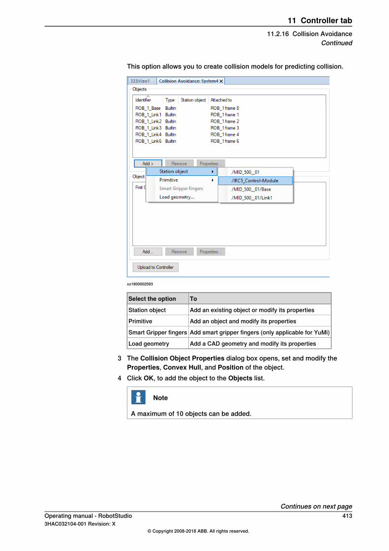
This option allows you to create collision models for predicting collision.
xx1800002593
ToSelect the option
Add an existing object or modify its propertiesStation object
Add an object and modify its propertiesPrimitive
Add smart gripper fingers (only applicable for YuMi)Smart Gripper fingers
Add a CAD geometry and modify its propertiesLoad geometry
3 The Collision Object Properties dialog box opens, set and modify theProperties, Convex Hull, and Position of the object.
4 Click OK, to add the object to the Objects list.
Note
A maximum of 10 objects can be added.
Continues on next pageOperating manual - RobotStudio 4133HAC032104-001 Revision: X
© Copyright 2008-2018 ABB. All rights reserved.
11 Controller tab11.2.16 Collision Avoidance
Continued

xx1800002592
To easily configure multiple objects, they can be paired.5 Under Object Pairs group, click Add, the Collision Pair properties dialog
box opens.
xx1800002594
6 Select the objects to be paired for collision avoidance from their respectivedrop-down lists.
7 Select the Exclude from collision check checkbox, to exclude the pairedobject from the collision check.
8 Select the Override safety distance checkbox, to override the preset safetydistance.
9 Click Ok, to pair the objects and add it to the Object Pairs list.
Continues on next page414 Operating manual - RobotStudio
3HAC032104-001 Revision: X© Copyright 2008-2018 ABB. All rights reserved.
11 Controller tab11.2.16 Collision AvoidanceContinued
10 Click Upload to Controller, to upload the configuration to the controller.Using the File Transfer feature a collision avoidance file can be transferred fromthe HOME folder of the virtual robot controller to the controller. For moreinformation, see File transfer on page 419.
LimitationsCollision Avoidance is a function included in the option Collision Detection.Collision Avoidance can only be used by six and seven axis serial link robots(bending backwards). It is supported by robots with track motion and single axispositioner (L-type).When jogging, Collision Avoidance will not be triggered if used together withresponsive jogging. The system parameter JogModemust be changed toStandard.The Collision Avoidance between 2 robots (or more) can only be achieved whenusing a MultiMove system.
CAUTION
Collision Avoidance shall not be used for safety of personnel.
For more information, see Application manual - Controller software IRC5.
Operating manual - RobotStudio 4153HAC032104-001 Revision: X
© Copyright 2008-2018 ABB. All rights reserved.
11 Controller tab11.2.16 Collision Avoidance
Continued

11.3 Features for real controllers
11.3.1 Request Write Access
OverviewYou need Write access for editing programs and configurations or in any otherway to change data on the controller.
Prerequisites for Write accessYou can get Write access to any controller as long as the prerequisites are fulfilled.
This has to be fulfilled:When the Controlleris in Mode:
The Write access must not be taken by any other user.Auto
The remote Write access must be granted on the FlexPendant. Forsafety reasons, a FlexPendant user can also recall this remote Writeaccess in manual mode.
Manual
If the prerequisites are not fulfilled you will be denied, or lose, the Write access.This means that if you have Write access in auto mode and the controller is switchedover to manual mode you will lose the Write access without any warning. This isbecause the FlexPendant unit by default has the Write access in manual mode,for safety reasons. The same will happen if the remote Write access in manualmode is recalled from the FlexPendant unit.
ResultThe Controller Status window will be updated when the request for Write accessis granted.If the Write access is denied, a message is displayed.
416 Operating manual - RobotStudio3HAC032104-001 Revision: X
© Copyright 2008-2018 ABB. All rights reserved.
11 Controller tab11.3.1 Request Write Access
11.3.2 Release Write Access
OverviewSeveral users can be logged on to a single controller but only one can have thewrite access. You can release the write access when you do not need it anymore.
ResultThe Controller Status window will be updated when your access right has changedfrom read/write to read only.
Operating manual - RobotStudio 4173HAC032104-001 Revision: X
© Copyright 2008-2018 ABB. All rights reserved.
11 Controller tab11.3.2 Release Write Access

11.3.3 Authenticate
OverviewThe data, functionality, and commands on a controller are protected by a UserAuthorization system (also called UAS). The UAS restricts the parts of the systemthe user has access to. Different users can have different access grants.You can perform the following functions from the Authenticate menu:
• Login as a Different User• Log off• Log off all controllers• Edit User Accounts• UAS Grant Viewer
Login as a Different User1 In the Authenticate menu, click Login as a Different User. The Add new
user dialog box appears.2 In the User Name box, enter the user name you want to log on as.3 In the Password box, enter the password for the user name you are logging
on as.4 Click OK.
Note: If you have previously logged on as a different user and wish to revert asdefault user, click Login as Default User.
Log offIn the Authenticate menu, click Log off to log the user off from the controller.
Login off all controllersIn the Authenticate menu, click Log off to log the user off from all the controllers.
Edit User AccountsFor more information on User Accounts, see User Accounts on page 430.
UAS Grant ViewerFor more information on UAS Grant Viewer, see UAS Grant Viewer on page 435.
418 Operating manual - RobotStudio3HAC032104-001 Revision: X
© Copyright 2008-2018 ABB. All rights reserved.
11 Controller tab11.3.3 Authenticate

11.3.4 File transfer
OverviewYou can transfer the files and folders between the PC and a controller through theFile Transfer window.
PrerequisitesThe following are the prerequisites to be met:
• The PC must be connected to the same network as the controller, orconnected to the service port of the controller.
• You must be logged on to the controller as a user with UAS grants that allowsfile transferring.
Transferring files and foldersUse this procedure to transfer files and folders between the PC and a controller:
1 In the Controller Tools group, click File Transfer.The File Transfer window appears.
2 In the PC explorer, browse to the folder from or to which you want to transferthe data.
3 In the Controller explorer, browse to the folder from or to which you wantto transfer the data.
4 Select the item to transfer from the list.To select several items at once, do one of the following:
then pressTo select
the SHIFT key and select the first and the last item.several adjacent items
the CTRL key and select each item.several non-adjacentitems
the keys CTRL + Aall items in the list
5 When the files and folder to transfer are selected, do one of the following:
then pressTo
CTRL + Xcut the files
CTRL + C, or click Arrowcopy the files
Continues on next pageOperating manual - RobotStudio 4193HAC032104-001 Revision: X
© Copyright 2008-2018 ABB. All rights reserved.
11 Controller tab11.3.4 File transfer
6 Place the insertion point either in the PC explorer or the Controller explorerand click CTRL + V.
Note
In the PC explorer or Controller explorer window, right-click to view thefollowing context menu:
• Transfer• One level up• Open• Refresh• Cut• Copy• Paste• Delete• Remove
420 Operating manual - RobotStudio3HAC032104-001 Revision: X
© Copyright 2008-2018 ABB. All rights reserved.
11 Controller tab11.3.4 File transferContinued
11.3.5 FlexPendant Viewer
OverviewFlexPendant Viewer is an add-in to RobotStudio that retrieves and displays ascreenshot from the FlexPendant. The screenshot is generated automatically atthe moment of the request.
PrerequisitesThe controller you want to retrieve screen shots from must be added to your robotview.A FlexPendant must be connected to the controller. If no FlexPendant is currentlyconnected (optionHot plug is installed and the jumper plug is used) then no screenshot can be retrieved.
Using FlexPendant Viewer1 Make sure you are connected to the controller.2 In the Controller Tools group, click the arrow next to the FlexPendant icon,
and then click FlexPendant Viewer.A screen shot will be displayed in the workspace.
3 To reload the screen shot, click Reload in the workspace.4 To set an automatic reload period for the screen shot, click on the menu
Tools, point to FlexPendant Viewer and click Configure.Set the desired reload period and select the check-boxActivated. Then clickOK.
Results on the controllerThe screenshot will automatically be saved as a file on the controller. When a newrequest is sent, a new screenshot is generated and saved, overwriting the previousfile.No message will be displayed on the FlexPendant.
Operating manual - RobotStudio 4213HAC032104-001 Revision: X
© Copyright 2008-2018 ABB. All rights reserved.
11 Controller tab11.3.5 FlexPendant Viewer

11.3.6 Import Options
Importing system options1 In the Configuration group, click Import Options to bring up a dialog box.2 In the Option source box, enter the path to the folder where the options to
import are located. You can also click the Browse button and browse to thefolder.
3 In theMedia Pool destination box, enter the path to the media pool you wantto store the options in. You can also click the Browse button and browse tothe media pool folder.
4 Select the options to import and click Import.To select several options at once, do one of the following:
then hold downTo select
the SHIFT key and select the first and the last option.several adjacent options
the CTRL key and select each option.several non-adjacent options
5 Click OK.
Removing system options1 In the Configuration group, click Import Options to bring up a dialog box.2 In the Media Pool destination list, enter the path to the media pool from
which you want to delete the options. You can also click the Browse buttonand browse to the media pool folder.
3 Select the options to delete and click Remove.To select several options at once, do one of the following:
then hold downTo select
the SHIFT key and select the first and the last option.several adjacent options
the CTRL key and select each option.several non-adjacent options
4 Click OK.
422 Operating manual - RobotStudio3HAC032104-001 Revision: X
© Copyright 2008-2018 ABB. All rights reserved.
11 Controller tab11.3.6 Import Options

11.3.7 Properties
OverviewYou can perform the following actions from the Properties menu:
• Renaming the controller• Setting the controller date and time• Setting the Controller ID• Viewing controller and system properties• Handling the Device Browser
Renaming the controllerThe controller name is an identification of the controller that is independent of thesystem or the software running on the controller. Unlike the controller ID, thecontroller name does not have to be unique for each controller.
Note
The controller name must be written with characters from the ISO 8859-1 (Latin1) character set.
1 In the Configuration group, click Properties, and then click Rename.The Rename Controller dialog box appears.
2 Enter the new name of the controller in the dialog box.3 Click OK.
The new name will be activated when the controller is restarted.You will be prompted to either click Yes to restart the controller immediatelyor click No to restart later.
Setting the controller date and timeYou can either set the date and time to the same as the network time server, oryou can specify the date and time manually.Use this procedure to set the controller date and time:
1 In the Configuration group, click Properties, and then click Date and Time.The Set Date and Time dialog box appears.
2 This dialog provides two options: Network Time and Manual Time.• Select Network Time and in the Time server address box, enter the
IP address of the network time server.• Select Manual time and then set the Date and Time in the boxes
provided. You can select the required time zone in the Time zone list.
Setting the Controller IDThe Controller ID is by default set to the serial number of the controller and isthereby a unique identifier of the controller.The Controller ID is a unique identifier for the controller and should not be changed.
Continues on next pageOperating manual - RobotStudio 4233HAC032104-001 Revision: X
© Copyright 2008-2018 ABB. All rights reserved.
11 Controller tab11.3.7 Properties
However, if the hard disk of the controller is replaced, the ID will be lost and youmust set it back to the serial number of the controller.
Note
You must Request Write Access to the controller before setting the controllerID.
1 In the Configuration group, click Properties, and then click Controller ID.The Set Controller ID dialog box appears.
2 Enter the Controller ID and then click OK.
Note
Use only characters from the ISO 8859-1 (Latin 1) character set and nomore than 40 characters.
Setting the IP address of the controllerYou can set the controller to receive the IP address from the network's DHCPserver or you can manually set the IP address of the controller.
1 On theController tab, in theConfiguration group, Click Properties and thenclick Network settings.The Network settings dialog opens.
2 Select Obtain an IP address automatically to set the controller to receivethe IP address from the network's DHCP server.ORSelect Use the following IP address and then enter the required IP addressand Subnet mask boxes to manually set the IP address of the controller.
Viewing controller and system propertiesYou can view the following properties for a controller and its running system.
System PropertiesController Properties
Control ModuleBoot Application
Drive Module #1Controller ID
Serial NumberController Name
System NameInstalled Systems
Network Connections
1 In the Configuration group, click Properties, and then click Controller andSystem Properties.The Controller and System Properties window appears.
2 In the tree view at the left of the window, browse to the node for which youwant to view the properties.The properties of the selected object are displayed in the Properties list tothe right of the window.
Continues on next page424 Operating manual - RobotStudio
3HAC032104-001 Revision: X© Copyright 2008-2018 ABB. All rights reserved.
11 Controller tab11.3.7 PropertiesContinued

Viewing the Device BrowserThe Device Browser displays the properties and trends of the various hardwareand software devices in a robot controller. To open the Device Browser, in theConfiguration group, click Properties, and then click Device Browser.
Displaying the properties of a deviceIn the tree view, browse to the node for which you want to view the properties andthen click it. The properties of the selected object, along with their correspondingvalues, are listed to the right of the tree view.
Updating the tree viewPress F5, to update the tree view.Alternatively, right-click inside the tree view pane, and then click Refresh.
Displaying a trendSelect a device in the tree view and then double-click any property, that has anumerical value, in the right-hand panel. This opens a trend view. The trend viewcollects data at a rate of one sample per second.
Hiding, stopping, starting or clearing a trendRight-click anywhere on the trend view and then click the required command.
Saving system diagnosticsYou can create a System Diagnostics data file from RobotStudio.To save a System Diagnostics data file to your PC, in the Configuration group,click Properties, and then click Save system diagnostics.
Operating manual - RobotStudio 4253HAC032104-001 Revision: X
© Copyright 2008-2018 ABB. All rights reserved.
11 Controller tab11.3.7 Properties
Continued
11.3.8 Go Offline
OverviewThe main purpose of this feature is to create a new station with a VC similar to theconnected real controller. This helps a robot technician to work offline, and notjust when connected to the real controller.
Using Go Offline1 Connect the PC to a real controller.2 On the Controller tab, click Request Write Access.
For more information on Request Write Access, see Request Write Accesson page 416.
3 Click Go Offline.The Go Offline dialog box is displayed.
4 Enter a name in the System Name field and browse for the location to savethe system.
5 Select the RobotWare version followed by the RobotWare Add-in versionand click OK.A new station is created with a VC with the same configuration as the realcontroller.
Note
A pre-requisite is that any RobotWare add-ins used by the system must beavailable on the PC. A Relation is automatically created between the virtualcontroller and the real controller. For more information on Relations, see Transferon page 406
426 Operating manual - RobotStudio3HAC032104-001 Revision: X
© Copyright 2008-2018 ABB. All rights reserved.
11 Controller tab11.3.8 Go Offline
11.3.9 Online Monitor
OverviewThis feature allows you to remotely monitor the robot connected to a real controller.It displays a 3D layout of the connected robot controller and enhances user’scurrent perception of reality by adding motion visualization augmentation.
Note
The Online Monitor shows TCP robots and TCP robots with track. Whenconnecting the Online Monitor to a virtual controller, the motion is shown only ifthe virtual controller is using Free-Run mode, not the Time Slice mode.
Using Online MonitorThe following procedure describes the Online Monitor feature in RobotStudio:
1 Connect the PC to a controller and add the controller. See Add Controller onpage 386.
2 Click Online Monitor.The 3D view of the mechanical units of the controller system is displayed inthe graphics window.
Note
The robot view is refreshed every second with the current joint values ofall the mechanical units.
Gravity parameters in online monitorOnline Monitor displays the orientation of a robot according to its gravityparameters. The Gravity Alpha, Gravity Beta and Gamma Rotation parametersdefine the rotation of the robot around the X, Y and Z axis in the world coordinatesystem. The Online Monitor orients the robot in the Graphical view according tothe gravity parameters.These parameters describe how the robot is oriented in relation with the floor orground, whether it is suspended (mounted on the ceiling), shelf mounted (mountedon the wall), or mounted on the regular floor. If the robot is configured to be mountedon the ceiling, it will be displayed upside down in the Online Monitor. You can setthese parameters in the Motion configuration file.For more information about gravity parameters, see Technical referencemanual - System parameters
Indication of TCPA cone is automatically created to indicate the active tool data being used. Thecone has its base in the robot wrist and its tip at the location of the tool data.
Continues on next pageOperating manual - RobotStudio 4273HAC032104-001 Revision: X
© Copyright 2008-2018 ABB. All rights reserved.
11 Controller tab11.3.9 Online Monitor
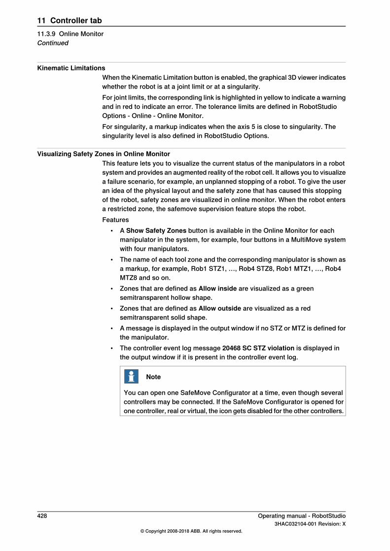
Kinematic LimitationsWhen the Kinematic Limitation button is enabled, the graphical 3D viewer indicateswhether the robot is at a joint limit or at a singularity.For joint limits, the corresponding link is highlighted in yellow to indicate a warningand in red to indicate an error. The tolerance limits are defined in RobotStudioOptions - Online - Online Monitor.For singularity, a markup indicates when the axis 5 is close to singularity. Thesingularity level is also defined in RobotStudio Options.
Visualizing Safety Zones in Online MonitorThis feature lets you to visualize the current status of the manipulators in a robotsystem and provides an augmented reality of the robot cell. It allows you to visualizea failure scenario, for example, an unplanned stopping of a robot. To give the useran idea of the physical layout and the safety zone that has caused this stoppingof the robot, safety zones are visualized in online monitor. When the robot entersa restricted zone, the safemove supervision feature stops the robot.Features
• A Show Safety Zones button is available in the Online Monitor for eachmanipulator in the system, for example, four buttons in a MultiMove systemwith four manipulators.
• The name of each tool zone and the corresponding manipulator is shown asa markup, for example, Rob1 STZ1, …, Rob4 STZ8, Rob1 MTZ1, …, Rob4MTZ8 and so on.
• Zones that are defined as Allow inside are visualized as a greensemitransparent hollow shape.
• Zones that are defined as Allow outside are visualized as a redsemitransparent solid shape.
• A message is displayed in the output window if no STZ or MTZ is defined forthe manipulator.
• The controller event log message 20468 SC STZ violation is displayed inthe output window if it is present in the controller event log.
Note
You can open one SafeMove Configurator at a time, even though severalcontrollers may be connected. If the SafeMove Configurator is opened forone controller, real or virtual, the icon gets disabled for the other controllers.
428 Operating manual - RobotStudio3HAC032104-001 Revision: X
© Copyright 2008-2018 ABB. All rights reserved.
11 Controller tab11.3.9 Online MonitorContinued
11.3.10 Visual SafeMove
OverviewVisual SafeMove is a 3D based configuration tool for SafeMove. The tool iscompletely integrated into the RobotStudio user interface and takes full advantageof the user interface elements such as tabs, browsers, and 3D graphics. VisualSafeMove is enabled for robots with the SafeMove option. It offers an intuitive wayto visualize and configure safety zones. Visual SafeMove works both with the realcontroller and the virtual controller. The Visual SafeMove configurator is availablealongside with the previous configurator.Only a safety user is allowed to download a configuration. A safety user must becreated before configuring SafeMove. For more information on visual safemoveconfigurator, see Operating Manual- SafeMove.
Note
You can open one SafeMove Configurator at a time, even though severalcontrollers may be connected. If the SafeMove Configurator is opened for onecontroller, real or virtual, the icon gets disabled for the other controllers.
Starting Visual SafeMove1 Start a RobotStudio station, a virtual controller, or connect to a real controller.2 In the RobotStudioController browser, right-click on the controller and select
Authenticate and then Login as a Different User.3 Select the safety user, for example, SafetyUser. Type the password and click
Login.4 In the Controller tab, click Online Monitor. (Not needed when running a
RobotStudio station.)5 In the Controller tab, click Safety, then select Visual SafeMove.
Operating manual - RobotStudio 4293HAC032104-001 Revision: X
© Copyright 2008-2018 ABB. All rights reserved.
11 Controller tab11.3.10 Visual SafeMove

11.3.11 User Accounts
OverviewAll the procedures below require the following steps to be taken before managingthe details:
1 In the Controller browser, select the controller to which you want to managea user or group
2 From theController tab, clickRequestWrite Access to provide write accessto the controller.
3 In the Controller tab, click Authenticate and select Edit User Accounts, foradministering UAS accounts, grants, and groups.
Users tabWith the Users tab you set which users will be able to log on to the controller andwhich groups the users shall belong to.
users-ta
Users tab Parts1 The Add button. Opens a dialog box for adding new users.2 The Edit button. Opens a dialog box for changing the log on name and
password of the user.3 The Delete button. Deletes the selected user account from the controller.
Continues on next page430 Operating manual - RobotStudio
3HAC032104-001 Revision: X© Copyright 2008-2018 ABB. All rights reserved.
11 Controller tab11.3.11 User Accounts
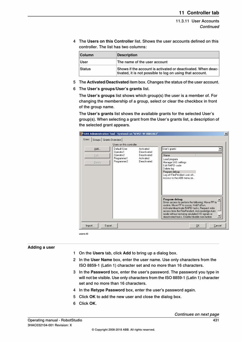
4 The Users on this Controller list. Shows the user accounts defined on thiscontroller. The list has two columns:
DescriptionColumn
The name of the user accountUser
Shows if the account is activated or deactivated. When deac-tivated, it is not possible to log on using that account.
Status
5 TheActivated/Deactivated item box. Changes the status of the user account.6 The User’s groups/User’s grants list.
The User’s groups list shows which group(s) the user is a member of. Forchanging the membership of a group, select or clear the checkbox in frontof the group name.The User’s grants list shows the available grants for the selected User’sgroup(s). When selecting a grant from the User’s grants list, a description ofthe selected grant appears.
users-t0
Adding a user1 On the Users tab, click Add to bring up a dialog box.2 In the User Name box, enter the user name. Use only characters from the
ISO 8859-1 (Latin 1) character set and no more than 16 characters.3 In the Password box, enter the user's password. The password you type in
will not be visible. Use only characters from the ISO 8859-1 (Latin 1) characterset and no more than 16 characters.
4 In the Retype Password box, enter the user's password again.5 Click OK to add the new user and close the dialog box.6 Click OK.
Continues on next pageOperating manual - RobotStudio 4313HAC032104-001 Revision: X
© Copyright 2008-2018 ABB. All rights reserved.
11 Controller tab11.3.11 User Accounts
Continued
Deleting a user1 On the Users tab, select the user to delete from the Users on this controller
list and click Delete.2 To the question Are you sure you want to remove this user?, answer Yes.3 Click OK.
Setting up group membership1 On the Users tab, select the user from the Users on this controller list.2 In the User’s groups list, select the groups the user shall be a member of.3 Click OK.
Changing a name or password1 On the Users tab, select the user to edit from the Users on this controller
list and click Edit user.This opens the Edit dialog box.
2 To change the user name, enter the new name in the User Name box. Useonly characters from the ISO 8859-1 (Latin 1) character set and no more than16 characters.
3 To change the password, enter the new password in the Password box, thenretype the password in the Retype Password box. Use only characters fromthe ISO 8859-1 (Latin 1) character set and no more than 16 characters.
4 Click OK to save the changes to the user and close the dialog box.5 Click OK.
Activating or deactivating a user1 On the Users tab, select the user from the Users on this controller list and
click the status text (Activated or Deactivated). An item box appears and youcan change the status.The user's new state is now displayed in the status column of the Users onthis controller list.
2 Click OK.
Exporting a user list1 On the Users tab, select the user from the Users on this controller list and
click Export.2 Browse to the destination folder and click OK. The File password dialog
opens, type in the password and click OK.3 This opens a Save as dialog box, in which you specify the name and location
for the file with the user list.
Importing a user list1 On the Users tab, select the user from the Users on this controller list and
click Import.2 Browse to the file location and click OK. The File password dialog opens,
type in the password and click OK.
Continues on next page432 Operating manual - RobotStudio
3HAC032104-001 Revision: X© Copyright 2008-2018 ABB. All rights reserved.
11 Controller tab11.3.11 User AccountsContinued
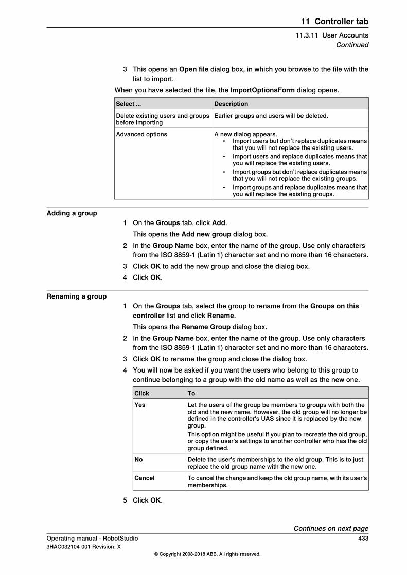
3 This opens an Open file dialog box, in which you browse to the file with thelist to import.
When you have selected the file, the ImportOptionsForm dialog opens.
DescriptionSelect ...
Earlier groups and users will be deleted.Delete existing users and groupsbefore importing
A new dialog appears.• Import users but don’t replace duplicates means
that you will not replace the existing users.• Import users and replace duplicates means that
you will replace the existing users.• Import groups but don’t replace duplicates means
that you will not replace the existing groups.• Import groups and replace duplicates means that
you will replace the existing groups.
Advanced options
Adding a group1 On the Groups tab, click Add.
This opens the Add new group dialog box.2 In the Group Name box, enter the name of the group. Use only characters
from the ISO 8859-1 (Latin 1) character set and no more than 16 characters.3 Click OK to add the new group and close the dialog box.4 Click OK.
Renaming a group1 On the Groups tab, select the group to rename from the Groups on this
controller list and click Rename.This opens the Rename Group dialog box.
2 In the Group Name box, enter the name of the group. Use only charactersfrom the ISO 8859-1 (Latin 1) character set and no more than 16 characters.
3 Click OK to rename the group and close the dialog box.4 You will now be asked if you want the users who belong to this group to
continue belonging to a group with the old name as well as the new one.
ToClick
Let the users of the group be members to groups with both theold and the new name. However, the old group will no longer bedefined in the controller's UAS since it is replaced by the newgroup.
Yes
This option might be useful if you plan to recreate the old group,or copy the user's settings to another controller who has the oldgroup defined.
Delete the user's memberships to the old group. This is to justreplace the old group name with the new one.
No
To cancel the change and keep the old group name, with its user'smemberships.
Cancel
5 Click OK.
Continues on next pageOperating manual - RobotStudio 4333HAC032104-001 Revision: X
© Copyright 2008-2018 ABB. All rights reserved.
11 Controller tab11.3.11 User Accounts
Continued

Deleting a group1 On the Groups tab, select the group to delete from the Groups on this
controller list and click Delete.2 You will now be asked if you want the users who belong to this group to
continue belonging to it though it is not valid.
ToClick
Let the users of the group remain members to it even if it is nolonger defined in the controller's UAS.
Yes
This option might be useful if you plan to recreate the group, orcopy the user's settings to another controller who has the groupdefined.
Delete the user's memberships to the group.No
Cancel the change and keep the group, with its user's member-ships.
Cancel
3 Click OK.
Giving grants to a group1 On the Groups tab, select the group from the Groups on this controller list.2 In the Controller grants/Application grants list, select the grants to give to
the group.3 Click OK.
434 Operating manual - RobotStudio3HAC032104-001 Revision: X
© Copyright 2008-2018 ABB. All rights reserved.
11 Controller tab11.3.11 User AccountsContinued

11.3.12 UAS Grant Viewer
OverviewThe UAS Grant Viewer page displays information about the grants provided to theuser currently logged in and the groups owning them.
1 In theAuthenticatemenu, clickUASGrant Viewer. TheUASGrantswindowappears.
en0900000852
Examples of common actions to perform
Necessary grantsAction
Modify controller propertiesRename the controllerRemote restart(A restart of the controller is necessary)
Modify configurationChange system parameters and load configura-tion files Remote restart
Administration of installed systemInstall a new system
Backup and savePerform a backupRemote restart(A restart of the controller is necessary)
Restore a backupRestore a backupRemote restart(A restart of the controller is necessary)
Load programLoad/delete modules
Load programCreate new module.
Edit RAPID codeEdit code in RAPID modules
Backup and saveSave modules and programs to disk
Execute programStart program execution from Task Window
Continues on next pageOperating manual - RobotStudio 4353HAC032104-001 Revision: X
© Copyright 2008-2018 ABB. All rights reserved.
11 Controller tab11.3.12 UAS Grant Viewer
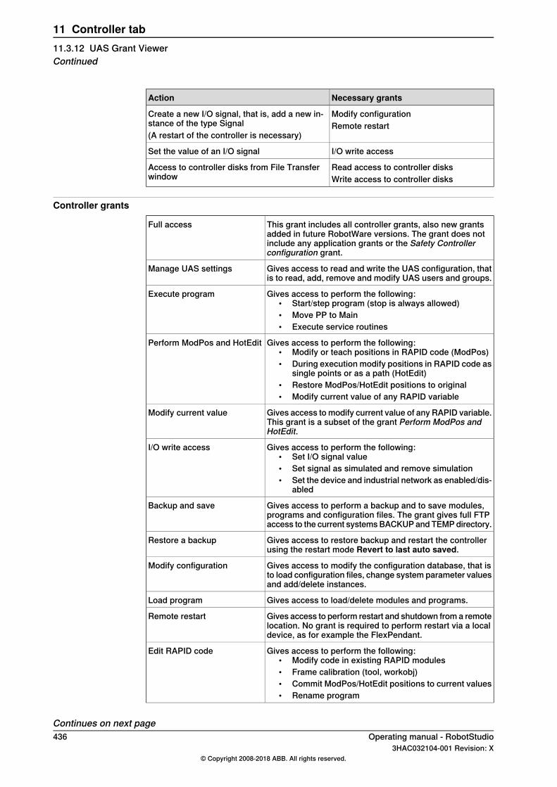
Necessary grantsAction
Modify configurationCreate a new I/O signal, that is, add a new in-stance of the type Signal Remote restart(A restart of the controller is necessary)
I/O write accessSet the value of an I/O signal
Read access to controller disksAccess to controller disks from File Transferwindow Write access to controller disks
Controller grants
This grant includes all controller grants, also new grantsadded in future RobotWare versions. The grant does notinclude any application grants or the Safety Controllerconfiguration grant.
Full access
Gives access to read and write the UAS configuration, thatis to read, add, remove and modify UAS users and groups.
Manage UAS settings
Gives access to perform the following:• Start/step program (stop is always allowed)• Move PP to Main• Execute service routines
Execute program
Gives access to perform the following:• Modify or teach positions in RAPID code (ModPos)• During execution modify positions in RAPID code as
single points or as a path (HotEdit)• Restore ModPos/HotEdit positions to original• Modify current value of any RAPID variable
Perform ModPos and HotEdit
Gives access to modify current value of any RAPID variable.This grant is a subset of the grant Perform ModPos andHotEdit.
Modify current value
Gives access to perform the following:• Set I/O signal value• Set signal as simulated and remove simulation• Set the device and industrial network as enabled/dis-
abled
I/O write access
Gives access to perform a backup and to save modules,programs and configuration files. The grant gives full FTPaccess to the current systems BACKUP and TEMP directory.
Backup and save
Gives access to restore backup and restart the controllerusing the restart mode Revert to last auto saved.
Restore a backup
Gives access to modify the configuration database, that isto load configuration files, change system parameter valuesand add/delete instances.
Modify configuration
Gives access to load/delete modules and programs.Load program
Gives access to perform restart and shutdown from a remotelocation. No grant is required to perform restart via a localdevice, as for example the FlexPendant.
Remote restart
Gives access to perform the following:• Modify code in existing RAPID modules• Frame calibration (tool, workobj)• Commit ModPos/HotEdit positions to current values• Rename program
Edit RAPID code
Continues on next page436 Operating manual - RobotStudio
3HAC032104-001 Revision: X© Copyright 2008-2018 ABB. All rights reserved.
11 Controller tab11.3.12 UAS Grant ViewerContinued
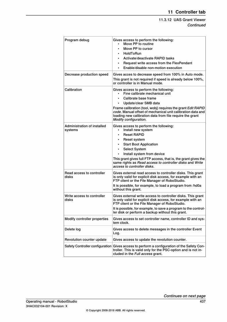
Gives access to perform the following:• Move PP to routine• Move PP to cursor• HoldToRun• Activate/deactivate RAPID tasks• Request write access from the FlexPendant• Enable/disable non-motion execution
Program debug
Gives acces to decrease speed from 100% in Auto mode.Decrease production speedThis grant is not required if speed is already below 100%,or controller is in Manual mode.
Gives access to perform the following:• Fine calibrate mechanical unit• Calibrate base frame• Update/clear SMB data
Frame calibration (tool, wobj) requires the grant Edit RAPIDcode. Manual offset of mechanical unit calibration data andloading new calibration data from file require the grantModify configuration.
Calibration
Gives access to perform the following:• Install new system• Reset RAPID• Reset system• Start Boot Application• Select System• Install system from device
This grant gives full FTP access, that is, the grant gives thesame rights as Read access to controller disks and Writeaccess to controller disks.
Administration of installedsystems
Gives external read access to controller disks. This grantis only valid for explicit disk access, for example with anFTP client or the File Manager of RoboStudio.
Read access to controllerdisks
It is possible, for example, to load a program from /hd0awithout this grant.
Gives external write access to controller disks. This grantis only valid for explicit disk access, for example with anFTP client or the File Manager of RoboStudio.
Write access to controllerdisks
It is possible, for example, to save a program to the control-ler disk or perform a backup without this grant.
Gives access to set controller name, controller ID and sys-tem clock.
Modify controller properties
Gives access to delete messages in the controller EventLog.
Delete log
Gives access to update the revolution counter.Revolution counter update
Gives access to perform a configuration of the Safety Con-troller. This is valid only for the PSC-option and is not in-cluded in the Full access grant.
Safety Controller configuration
Continues on next pageOperating manual - RobotStudio 4373HAC032104-001 Revision: X
© Copyright 2008-2018 ABB. All rights reserved.
11 Controller tab11.3.12 UAS Grant Viewer
Continued
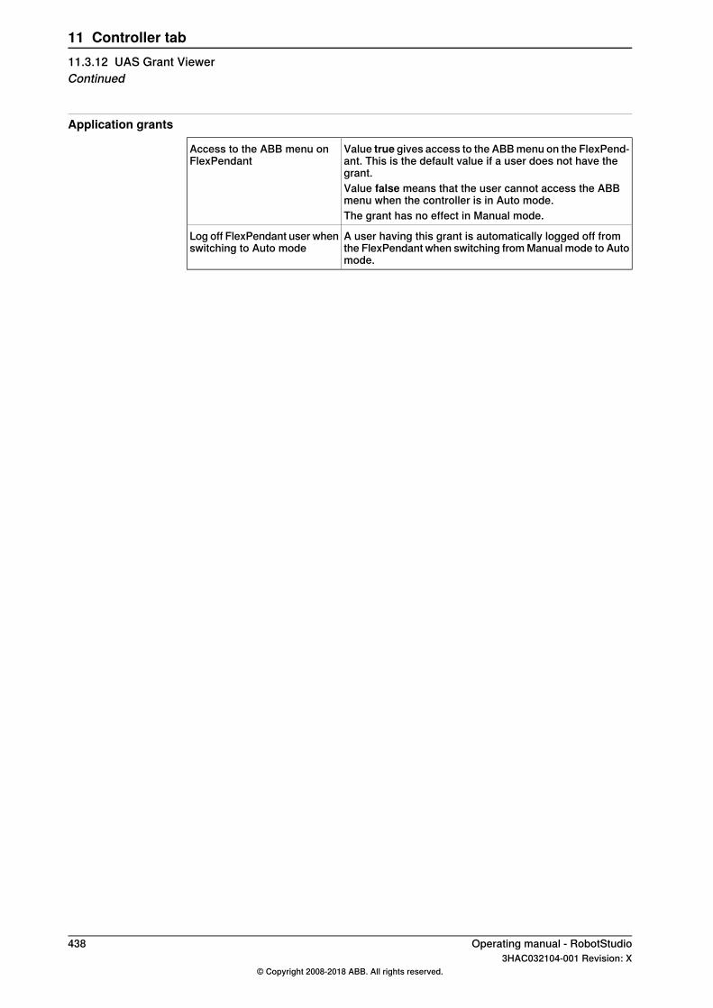
Application grants
Value true gives access to the ABB menu on the FlexPend-ant. This is the default value if a user does not have thegrant.
Access to the ABB menu onFlexPendant
Value false means that the user cannot access the ABBmenu when the controller is in Auto mode.The grant has no effect in Manual mode.
A user having this grant is automatically logged off fromthe FlexPendant when switching from Manual mode to Automode.
Log off FlexPendant user whenswitching to Auto mode
438 Operating manual - RobotStudio3HAC032104-001 Revision: X
© Copyright 2008-2018 ABB. All rights reserved.
11 Controller tab11.3.12 UAS Grant ViewerContinued

11.3.13 Integrated Vision
The Integrated Vision system provides a robust and easy‐to‐use vision system forgeneral purpose Vision Guided Robotics (VGR) applications. The system featuresa complete software and hardware solution that is fully integrated with the IRC5robot controller and the RobotStudio programming environment. The visioncapability leverages on the Cognex® In-Sight® smart camera family, with embeddedimage processing and an Ethernet communication interface.RobotStudio has been equipped with a vision programming environment thatexposes the full palette of Cognex EasyBuilder® functionality with robust tools forpart location, part inspection and identification. The RAPID programming languagehas been extended with dedicated instructions and error tracing for cameraoperation and vision guidance.For more information, see Application manual - Integrated Vision
Operating manual - RobotStudio 4393HAC032104-001 Revision: X
© Copyright 2008-2018 ABB. All rights reserved.
11 Controller tab11.3.13 Integrated Vision

11.3.14 Jobs
OverviewThe Jobs feature allows you to perform certain actions on a large population ofrobot controllers. A Job is defined by a Device list and an Action. The Action willbe carried out for all controllers in the Device list.
Jobs tabThe Jobs feature is managed from the Jobs Contextual tab. On the Controller tab,in the Controller Tools group, click Jobs to open the Jobs Contextual tab.The Jobs Contextual tab contains the following groups.
DescriptionGroups
A user-defined group of robot controllers for applying a job. Device lists canbe reused between jobs.
Device Lists
A command group containing various job options.Jobs
Device Lists groupThe Device Lists group contains the following commands and controls.
DescriptionCommands
Opens a new empty device list window for creating a new group of robotcontrollers.
New Device List
Opens a previously saved device list to edit or review.Open Device List
Saves the contents of an active device list window to disk in .xlsx format.These files can be edited in Microsoft Excel without changing the gridstructure.
Save Device List
Populates the active device list window with all controllers that Netscanfinds on the local subnet.
Scan Subnet
Jobs groupThe Jobs group contains the following commands and controls.
DescriptionCommands
Opens a new job window.New job
Provides options, Save Job and Edit Job Templates.• Save Job : Saves the job specification as an .xml file.• Edit Job Templates: Allows you to edit an existing template
file.
Templates
Verifies the status of the group of robot controllers.Verify
Executes the user-selected action.Execute
Temporarily stops an active action.Pause
Resumes the paused action.Resume
Aborts the active job.Cancel
Continues on next page440 Operating manual - RobotStudio
3HAC032104-001 Revision: X© Copyright 2008-2018 ABB. All rights reserved.
11 Controller tab11.3.14 Jobs
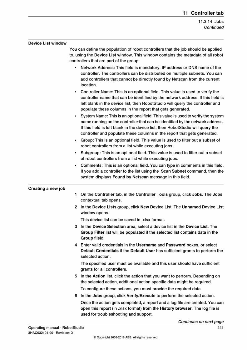
Device List windowYou can define the population of robot controllers that the job should be appliedto, using the Device List window. This window contains the metadata of all robotcontrollers that are part of the group.
• Network Address: This field is mandatory. IP address or DNS name of thecontroller. The controllers can be distributed on multiple subnets. You canadd controllers that cannot be directly found by Netscan from the currentlocation.
• Controller Name: This is an optional field. This value is used to verify thecontroller name that can be identified by the network address. If this field isleft blank in the device list, then RobotStudio will query the controller andpopulate these columns in the report that gets generated.
• System Name: This is an optional field. This value is used to verify the systemname running on the controller that can be identified by the network address.If this field is left blank in the device list, then RobotStudio will query thecontroller and populate these columns in the report that gets generated.
• Group: This is an optional field. This value is used to filter out a subset ofrobot controllers from a list while executing jobs.
• Subgroup: This is an optional field. This value is used to filter out a subsetof robot controllers from a list while executing jobs.
• Comments: This is an optional field. You can type in comments in this field.If you add a controller to the list using the Scan Subnet command, then thesystem displays Found by Netscan message in this field.
Creating a new job1 On the Controller tab, in the Controller Tools group, click Jobs. The Jobs
contextual tab opens.2 In the Device Lists group, click New Device List. The Unnamed Device List
window opens.This device list can be saved in .xlsx format.
3 In the Device Selection area, select a device list in the Device List. TheGroup Filter list will be populated if the selected list contains data in theGroup fileld.
4 Enter valid credentials in the Username and Password boxes, or selectDefault Credentials if the Default User has sufficient grants to perform theselected action.The specified user must be available and this user should have sufficientgrants for all controllers.
5 In the Action list, click the action that you want to perform. Depending onthe selected action, additional action specific data might be required.To configure these actions, you must provide the required data.
6 In the Jobs group, click Verify/Execute to perform the selected action.Once the action gets completed, a report and a log file are created. You canopen this report (in .xlsx format) from the History browser. The log file isused for troubleshooting and support.
Continues on next pageOperating manual - RobotStudio 4413HAC032104-001 Revision: X
© Copyright 2008-2018 ABB. All rights reserved.
11 Controller tab11.3.14 Jobs
Continued
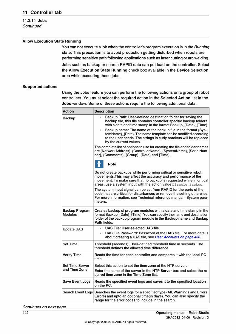
Allow Execution State RunningYou can not execute a job when the controller's program execution is in theRunningstate. This precaution is to avoid production getting disturbed when robots areperforming sensitive path following applications such as laser cutting or arc welding.Jobs such as backup or search RAPID data can put load on the controller. Selectthe Allow Execution State Running check box available in the Device Selectionarea while executing these jobs.
Supported actionsUsing the Jobs feature you can perform the following actions on a group of robotcontrollers. You must select the required action in the Selected Action list in theJobs window. Some of these actions require the following additional data.
DescriptionAction• Backup Path: User-defined destination folder for saving the
backup file, this file contains controller specific backup folderswith a date and time stamp in the format Backup_{Date}_{Time}.
• Backup name: The name of the backup file in the format {Sys-temName}_{Date}. The name template can be modified accordingto the user needs. The strings in curly brackets will be replacedby the current values.
The complete list of options to use for creating the file and folder namesare {NetworkAddress}, {ControllerName}, {SystemName}, {SerialNum-ber}, {Comments}, {Group}, {Date} and {Time}.
Note
Do not create backups while performing critical or sensitive robotmovements.This may affect the accuracy and performance of themovement. To make sure that no backup is requested while in criticalareas, use a system input with the action value Disable Backup.The system input signal can be set from RAPID for the parts of thecode that are critical for disturbances or remove the setting otherwise.For more information, see Technical reference manual - System para-meters.
Backup
Creates backup of program modules with a date and time stamp in theformat Backup_{Date}_{Time}. You can specify the name and destinationfolder of the backup program module in the Backup name and BackupPath fields.
Backup ProgramModules
• UAS File: User-selected UAS file.• UAS File Password: Password of the UAS file. For more details
about creating a UAS file, see User Accounts on page 430.
Update UAS
Threshold (seconds): User-defined threshold time in seconds. Thethreshold defines the allowed time difference.
Set Time
Reads the time for each controller and compares it with the local PCtime.
Verify Time
Select this action to set the time zone of the NTP server.Set Time Serverand Time Zone Enter the name of the server in the NTP Server box and select the re-
quired time zone in the Time Zone list.
Reads the specified event logs and saves it to the specified locationon the PC.
Save Event Logs
Searches the event logs for a specified type (All, Warnings and Errors,Errors) and upto an optional time(in days). You can also specify therange for the error codes to include in the search.
Search Event Logs
Continues on next page442 Operating manual - RobotStudio
3HAC032104-001 Revision: X© Copyright 2008-2018 ABB. All rights reserved.
11 Controller tab11.3.14 JobsContinued

DescriptionAction
You can read RAPID Data, I/O Signal values, Configuration parametersand device information with this function.
• For RAPID Data, you must specify the URL of the RAPID instanceas Task/Module/Data or only Task/Data, for example,T_ROB1/Module1/myToolData, or T_ROB1/myToolData. Theresult will be the value of the instance.
• For I/O Signals, you must specify the name of the signal, for ex-ample, mySignal. The result will be the signal value.
• For configuration parameters, you must specify the URL to theinstance attribute in the form DOMAIN/TYPE/InstanceName/At-tributeName, for example MOC/ARM_LOAD/r1_load_4/mass orEIO/EIO_SIGNAL/diMySignal/access.
• Select the Devices option, to read device information like MainComputer Fan Speed, Main Computer Module Temperature,CPU Temperature and Free RAPID Memory(MB) by selectingthe required option in the Copy From the device browser.To read other properties, copy the device property ID from theDevice Browser. Right-click the desired property and selectCopy device property ID from the context menu. Paste the IDinto the text field above.
See the Technical reference manual - System parameters for the namesof the domains, types and attributes. The result will be the value of theattribute.
Read Single Data
Searches for RAPID instances that matches the specified search pat-terns. You can restrict the search to tasks, modules, data types andnames of record fields that match the specified pattern.
Search RAPIDData
Searches for lines that contain the specified text string. You can restrictthe search to tasks or modules that match a certain name pattern.
Search RAPIDText
Writes the selected file or directory to the specified target directory.Write File or Direct-ory
Reads the selected file or directory from HOME folder or from a task.Read File or Direct-ory
Reads the options, languages and media versions of the controllers.System Informa-tion
Invokes an external executable.• External Tool Path: Location of the folder where the external tool
is placed.• Arguments: User specified arguments which the external tool
passes, for example {SystemName}, { Network address},{Group}and so on.
• Timeout(s): Specifies command time out period.
Run External Tool
Compares two folders and generates a report with the differences.These reports are available in two formats, Excel and xml files. Thesereports are not exclusive to Compare Folder.
Compare Folder
Reads the System Diagnostics file and saves it to the specified locationon the PC.
Save System Dia-gnostics
Reads the Assessment Data and saves it to the specified location onthe PC.
Save AssessmentData
Continues on next pageOperating manual - RobotStudio 4433HAC032104-001 Revision: X
© Copyright 2008-2018 ABB. All rights reserved.
11 Controller tab11.3.14 Jobs
Continued
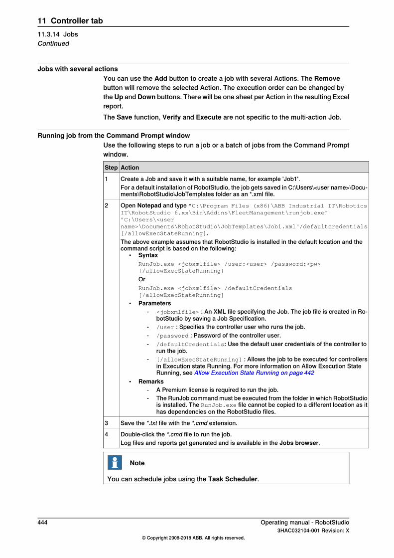
Jobs with several actionsYou can use the Add button to create a job with several Actions. The Removebutton will remove the selected Action. The execution order can be changed bythe Up and Down buttons. There will be one sheet per Action in the resulting Excelreport.The Save function, Verify and Execute are not specific to the multi-action Job.
Running job from the Command Prompt windowUse the following steps to run a job or a batch of jobs from the Command Promptwindow.
ActionStep
Create a Job and save it with a suitable name, for example 'Job1'.1For a default installation of RobotStudio, the job gets saved in C:\Users\<user name>\Docu-ments\RobotStudio\JobTemplates folder as an *.xml file.
Open Notepad and type "C:\Program Files (x86)\ABB Industrial IT\RoboticsIT\RobotStudio 6.xx\Bin\Addins\FleetManagement\runjob.exe""C:\Users\<username>\Documents\RobotStudio\JobTemplates\Job1.xml"/defaultcredentials[/allowExecStateRunning].
2
The above example assumes that RobotStudio is installed in the default location and thecommand script is based on the following:
• SyntaxRunJob.exe <jobxmlfile> /user:<user> /password:<pw>[/allowExecStateRunning]
OrRunJob.exe <jobxmlfile> /defaultCredentials[/allowExecStateRunning]
• Parameters- <jobxmlfile> : An XML file specifying the Job. The job file is created in Ro-
botStudio by saving a Job Specification.- /user : Specifies the controller user who runs the job.- /password : Password of the controller user.- /defaultCredentials: Use the default user credentials of the controller to
run the job.- [/allowExecStateRunning] : Allows the job to be executed for controllers
in Execution state Running. For more information on Allow Execution StateRunning, see Allow Execution State Running on page 442
• Remarks- A Premium license is required to run the job.- The RunJob command must be executed from the folder in which RobotStudio
is installed. The RunJob.exe file cannot be copied to a different location as ithas dependencies on the RobotStudio files.
Save the *.txt file with the *.cmd extension.3
Double-click the *.cmd file to run the job.4Log files and reports get generated and is available in the Jobs browser.
Note
You can schedule jobs using the Task Scheduler.
444 Operating manual - RobotStudio3HAC032104-001 Revision: X
© Copyright 2008-2018 ABB. All rights reserved.
11 Controller tab11.3.14 JobsContinued

11.4 Features for virtual controllers
11.4.1 Virtual FlexPendant
Opening a Virtual FlexPendantYou can open a virtual FlexPendant in one of the following ways:
1 On the Controller tab, in the Controller Tools group, click the arrow next tothe FlexPendant icon, and then click Virtual FlexPendant.
2 Press the keyboard shortcut, CTRL + F5.
Note
The Virtual FlexPendant is applicable while running a virtual controller.For information on specifying the appearance and placement of virtualFlexPendant, see Options on page 218.
Note
RobotStudio does not support non-motion execution option. This option can beset to prevent the real controller from moving, even when, the program isexecuting. RobotStudio will ignore this option and move the robot. The non-motionexecution option applies to virtual controllers only.
Operating manual - RobotStudio 4453HAC032104-001 Revision: X
© Copyright 2008-2018 ABB. All rights reserved.
11 Controller tab11.4.1 Virtual FlexPendant
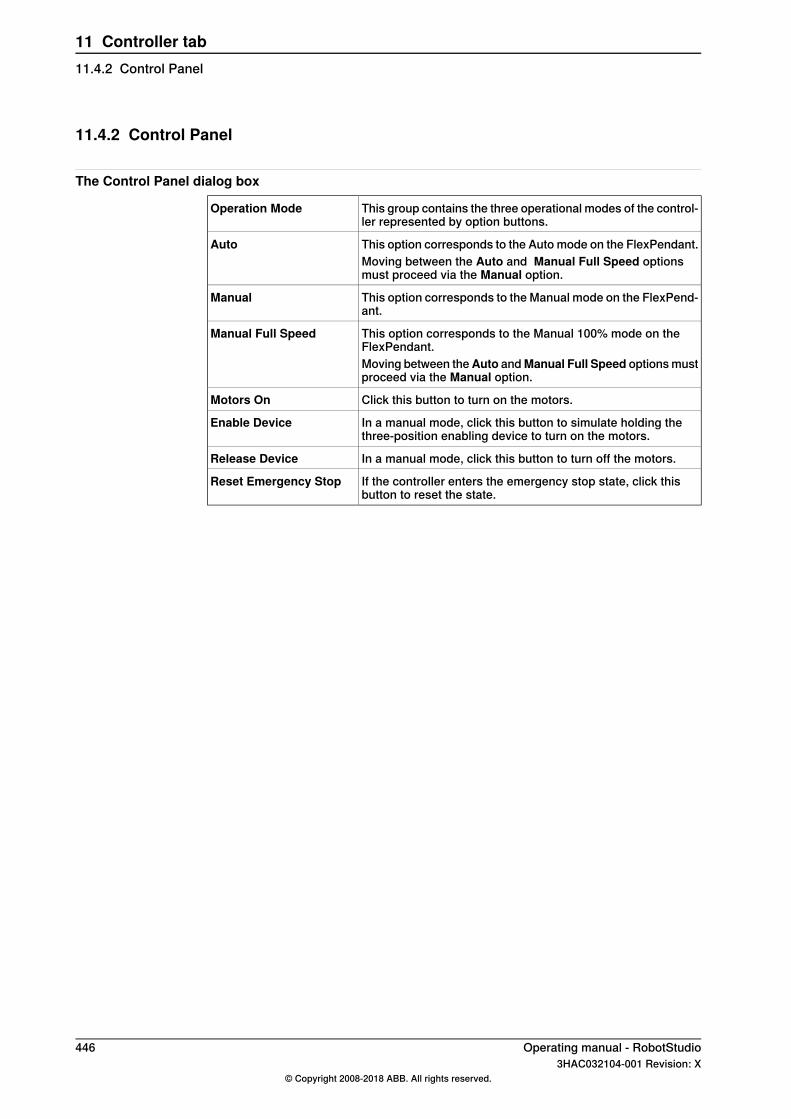
11.4.2 Control Panel
The Control Panel dialog box
This group contains the three operational modes of the control-ler represented by option buttons.
Operation Mode
This option corresponds to the Auto mode on the FlexPendant.AutoMoving between the Auto and Manual Full Speed optionsmust proceed via the Manual option.
This option corresponds to the Manual mode on the FlexPend-ant.
Manual
This option corresponds to the Manual 100% mode on theFlexPendant.
Manual Full Speed
Moving between theAuto andManual Full Speed options mustproceed via the Manual option.
Click this button to turn on the motors.Motors On
In a manual mode, click this button to simulate holding thethree-position enabling device to turn on the motors.
Enable Device
In a manual mode, click this button to turn off the motors.Release Device
If the controller enters the emergency stop state, click thisbutton to reset the state.
Reset Emergency Stop
446 Operating manual - RobotStudio3HAC032104-001 Revision: X
© Copyright 2008-2018 ABB. All rights reserved.
11 Controller tab11.4.2 Control Panel

11.4.3 Shutdown
Shutting down a controller1 In the Controller browser, select the controller to shut down.2 Select the controller.3 Follw these steps to shutdown a controller:
• On the Controller tab, in Controller Tools group, click Restart andthen click Shutdown to shutdown a virtual controller.
• On the Controller tab, in Controller Tools group, click Restart andthen click Shutdown main computer to shutdown a real controller.
Operating manual - RobotStudio 4473HAC032104-001 Revision: X
© Copyright 2008-2018 ABB. All rights reserved.
11 Controller tab11.4.3 Shutdown
11.4.4 Set Task Frames
Modifying Task frame1 On the Controller tab, in the Virtual Controller group, click Task Frames.
The Modify Task Frames dialog box appears.2 Set the reference to World, UCS, or Local.3 Edit the position and orientation of task frames in the Task Frames coordinate
box.4 Click Apply.
To the question, Do you also want to move the Base Frames(s)?• Click Yes to move the base frame, but keeps its relative placement to
the task frame.• Click No. The following question appears Do you want to update the
controller configuration and restart?. Click Yes to restart the controllerand update the base frame configuration of the connected VC.
Note
If there are any stationary RAPID objects (tooldata, workobjects) connectedto the robot, the following question appears Do you want to keep thepositioning of all stationary RAPID objects?
• Click Yes to keep all the stationary RAPID objects in their globalcoordinates.
• Click No to move all the stationary RAPID objects along with the baseframe (same coordinates relative to base frame).
448 Operating manual - RobotStudio3HAC032104-001 Revision: X
© Copyright 2008-2018 ABB. All rights reserved.
11 Controller tab11.4.4 Set Task Frames
11.4.5 Edit System
OverviewThe Edit System window contains functions for making and viewing advancedsystem configurations, such as changing controller and baseframe positions,calibrating and setting up external axes.The left side of the Edit System window contains a hierarchical tree with which youbrowse to different aspects of the system. The right side contains a property sheetfor the aspect selected in the tree. Below are short descriptions of the propertysheets for each aspect node of the tool.
CAUTION
Editing the system may result in corrupted systems or unexpected robotbehaviors. Be sure to understand the effects of the changes before proceeding.
The System nodeThe system node contains a box with information about the system and a buttonfor loading new parameters (configuration files) to the system.
The task nodeThe task node has no property page.
The mechanism folder nodeThe property page of this node contains controls for mapping and setting axis andjoints. It is from this page you set up external axes.
The mechanism library nodeThe property page of this node contains controls for changing the baseframe ofthe robot or mechanism. Here, too, you specify whether the baseframe is movedby another mechanism (coordinated motion), like a track external axis.
Updating the baseframe position1 Move the mechanical unit (robot or external axis) to its new location using
the ordinary tools for moving and placing objects.2 In the Controller browser, select the controller for the mechanical unit.3 On the Controller tab, in the Virtual Controller group, click Edit System.
This opens the System Configuration dialog.4 Select the node for the mechanical unit in the hierarchical tree. The baseframe
property sheet for the robot is now displayed.5 Select the baseframe position values to use after restarting the robot.
ToSelect
Reset all changes to the baseframe made since the lasttime the system was started.
Controller values
Continues on next pageOperating manual - RobotStudio 4493HAC032104-001 Revision: X
© Copyright 2008-2018 ABB. All rights reserved.
11 Controller tab11.4.5 Edit System
ToSelect
Reset all changes made to the baseframe since the lasttime the station was saved.
Stored station values
Optionally, you can enter new values in the baseframecoordinate boxes (relative to the controller world coordin-ate system).
Read and use the current location of the baseframe.Use current station val-ues Optionally, you can enter new values in the baseframe
coordinate boxes (relative to the controller world coordin-ate system).
6 Click OK.
Note
For information on adding a track from the Edit System tool, see Track motionof type RTT or IRBTx003 on page 88.
Calibrating the baseframe positionThe positioner mechanism is placed according to the base frame values of thevirtual controller. When a virtual controller is created from backup, in which, thepositioner was calibrated online using four points method, and if the positionerwas not in its sync position at the first calibration point, then the positionermechanism will not be aligned with the system's task frame .You can calibrate base frame values to realign the positioner mechanism with thesystem's task frame.
1 In the controller tab, click Edit System. The System Configuration dialogopens.
2 In the System Configuration window, select the positioner mechanism andthen click Calibrate.The Base Frame Calibration Position dialog opens.
3 From the System Configuration dialog, copy the Orientation values underBase Frame and paste these values in the boxes under Orientation in theBase Frame Calibration Position dialog.
4 ClickApply and then clickOK. You must restart the controller when prompted.The positioner mechanism will be aligned with the system's task frame now.Any object attached to the positioner will take the orientation of the positioner.
450 Operating manual - RobotStudio3HAC032104-001 Revision: X
© Copyright 2008-2018 ABB. All rights reserved.
11 Controller tab11.4.5 Edit SystemContinued
12 RAPID tab12.1 Overview of the RAPID tab
The RAPID tab provides tools and functionalities for creating, editing, and managingRAPID programs. You can manage RAPID programs which are online on a realcontroller, offline on a virtual controller, or standalone programs which are not partof a system.
Operating manual - RobotStudio 4513HAC032104-001 Revision: X
© Copyright 2008-2018 ABB. All rights reserved.
12 RAPID tab12.1 Overview of the RAPID tab
12.2 Synchronize to Station
Synchronizing to the station1 On the RAPID tab, in the Access group, click the arrow next to the
Synchronize icon, and then click Synchronize to Station.2 Select the paths to be synchronized to the station from the list.3 Click OK.
The message Synchronization to Station completed is displayed in theOutput window.
RAPID can be synchronized from the files of the HOME folder as an alternative:• In the Controller browser, under Home folder, right-click any file and then
click Synchronize to Station to synchronize data and procedures of theselected file into the station.
• In the Controller browser, under Home folder, right-click any file and thenclick Synchronize to File to synchronize data and procedures from the statoninto the selected file.Before selecting this option, you must synchronize the selected file to thestation. Using the Synchronize to File option can confilict with thesynchronize to RAPID option.
Limitations• Robtargets that are local to a procedure are not supported by Synchronize
to Station. Only robtargets that are local to a module are supported.• RobotStudio does not fully support instructions using Offs or RelTool
functions. These are synchronized and will appear in the element browser,but commands such as View Tool at Target and Locate Target will not work.Targets used in the instructions will not be visible in graphics. However,instructions can be programmed and edited using the RAPID Editor and canbe simulated using the virtual controller.
• RobotStudio does not support RAPID programs containing arrays of tooldata,robtargets and workobjects. These programs will not be synchronized to thestation.
• Workobjects and tooldata that are shared between several tasks must bespecified in RAPID with its full value for each task when programming offlinewith RobotStudio. This will trigger a warning Initial value for PERS not updatedin the controller event log. You may ignore this warning. However, you mustcarefully ensure that the RAPID variable definitions are the same in all tasks,otherwise you may get unexpected behavior.
452 Operating manual - RobotStudio3HAC032104-001 Revision: X
© Copyright 2008-2018 ABB. All rights reserved.
12 RAPID tab12.2 Synchronize to Station
12.3 Synchronize to RAPID
Synchronizing to RAPID1 On the RAPID tab, in the Access group, click the arrow next to the
Synchronize icon, and then click Synchronize to RAPID.2 Select the elements to be synchronized from the list.3 Click OK.
The message Synchronization to RAPID completed is displayed in theOutput window.
Note
This function is also present in the Controller group on the Home tab.
Operating manual - RobotStudio 4533HAC032104-001 Revision: X
© Copyright 2008-2018 ABB. All rights reserved.
12 RAPID tab12.3 Synchronize to RAPID
12.4 Edit RAPID code
Editing RAPID code using RAPID EditorThe RAPID editor enables you to view and edit programs loaded into a controller,both real and virtual. The integrated RAPID editor is useful for editing all robottasks other than robot motion. With the RAPID editor you can edit the RAPID codeof the program modules and system modules. Each module you open appears inan editor window of its own, where you can add or edit RAPID code.For examples of using the RAPID editor, see Examples of using the RAPID editoron page 483.
General RAPID Editor featuresThe following are the general features of the RAPID Editor:
• Read-only documents - If the document is read-only (for example, due tolack of mastership), then the background of the editor area will be light grayinstead of the normal white. Typing in an editor that is in the read-only stateresults in a dialog asking you whether RobotStudio should acquire writeaccess.
• Syntax highlighting - Text is highlighted in different colors depending ontheir token classification (such as keyword, identifier and so on). You canconfigure these colors in the File tab, under Options:Robotics:RAPID Editor.For more information, see Options:Robotics:Text Editor on page 221.In addition to token classification, the editor also shows different colors forbuilt-in and installed identifiers (such as MoveL) and also for identifiersdeclared in user code.
• Quick-Info tooltips - When you hover the mouse pointer over a symbol (suchas a data declaration or procedure call), a tooltip is displayed describing thesymbol. For many built-in symbols (such as MoveJ) a short description isalso displayed. For symbols corresponding to a data declaration, the currentvalue is also displayed.
• Context-sensitive help - Pressing F1 when the cursor is on a RAPIDprogramming construct, such as an instruction, opens the related section inthe RAPID reference manual, instead of the main RobotStudio help.
• Auto-indent cursor on return - When you press Enter, the cursor isautomatically indented by the appropriate amount on the following line. Forexample, after typing a PROC header, pressing ENTER will indent the cursorone tab (or the corresponding number of spaces, depending on settings).
• Completion list - When you type in code in the editor, a pop-menu whichlists possible code suggestion maybe displayed depending on the kind ofRAPID code construct being written. The suggestions listed also depend onwhere in the document the cursor is.Pressing comma (,), semi-colon (;), colon (:), equal sign (=), Spacebar, Tab,or Enter keys automatically inserts the selected item. Press Esc to cancelthe list.
Continues on next page454 Operating manual - RobotStudio
3HAC032104-001 Revision: X© Copyright 2008-2018 ABB. All rights reserved.
12 RAPID tab12.4 Edit RAPID code
• Auto-completion - After typing or completing a procedure call (such asMoveJ), pressing the Tab key will fill in all required parameters. Note thatthis is only available for certain built-in procedures, such as those listed inthe Insert Instruction menu.
• Argument information - While typing in procedure calls and function calls,tooltips showing argument information are displayed.
• Collapsible regions - All regions of the code can be collapsed. In the RAPIDtab, click Outlining to access this functionality. You can either collapse orexpand all regions or can select a particular region to collapse or expand.
• Error highlighting - Red squiggly lines appear under errors in the code. Allsyntax errors and a subset of semantic errors are indicated in this manner.
• Zooming in and out - In the RAPID editor you can zoom in and zoom out ofthe code display. Click the plus (+) and minus (-) buttons at the top rightcorner of the RAPID editor window to zoom in and zoom out.
Tip
The Zoom in Zoom out feature is also present in the RAPID Tasks, RapidEditor, Configuration Editor, Event viewer, and I/O windows.
• Cut, copy, paste and drag and drop - These standard commands forclipboard handling of text are supported.
• Undo and redo - Standard commands for undo and redo operations aresupported.
• Selection modes - You can select text by character, row and column.• Line numbers - Line numbers for the RAPID code lines are displayed in the
left margin of the editor.• Keyboard shortcuts - For keyboard shortcuts in the RAPID Editor, see
Keyboard shortcuts on page 76.• RAPID compare- To compare the controller version of RAPID module with
the editor/file version, right-click an open module and then click EditorVersion or File. You can compare folders and files using theCompare button.In the Find group, click Compare and then select the required comparisonoptions like Controller Version and Editor, Controller Version and File andEditor and File.You can configure the comparison results either to show all content with thedifferences highlighted or with only the differences between files/folders.Select Options like BackInfo, PERS variables, Comments, Character caseand White space to add filters. The BackInfo option excludes the timestampof the Backinfo.txt file from comparison.
Starting the RAPID EditorTo open a RAPID module in the RAPID editor, in the Controller browser right-clickon a RAPID module, and then click RAPID Editor.
Continues on next pageOperating manual - RobotStudio 4553HAC032104-001 Revision: X
© Copyright 2008-2018 ABB. All rights reserved.
12 RAPID tab12.4 Edit RAPID code
Continued
The RAPID code of the module opens in the editor window.
Tip
You can view the graphical layout, without closing the editor, by clicking thegraphics window tab.
Editing a RAPID programThe Edit group on the RAPID tab has commands which help in editing the lines ofcode in the RAPID Editor. Other than standard functions such as Cut, Copy, andPaste, the following functions are present in the Edit group:
• Comment – To comment out selected linesUncomment – To uncomment commented linesThe comment and uncomment buttons in the ribbon will add/remove commentcharacters (“!”) at the beginning of the selected line(s).
• Indent – To increase the indent of selected line(s) by four white spacesUnindent – To decrease the indent of selected line(s) by four white spacesThe indent and unindent buttons in the ribbon will move the selected codeline(s) one tab position to the right/left.
• Format Document - Auto-formats the active document by arranging thespaces and tabs in the RAPID code.
• Adjust case - To change RAPID keywords from lowercase to uppercase. Thisfunction operates on the current document.
• Format Selection – This function is similar to Format Document, but with thedifference that it operates on currently selected text.
• Convert Spaces to Tabs - Converts consecutive spaces to the correspondingnumber of tabs. This function operates on the current selection.
• Convert Tabs to Spaces - Does the opposite of function above.
Note
To make formatting easier, the tabs and white spaces can be indicated byarrows and dots, respectively. To enable this go to Options:Robotics:RAPIDEditor (Options:Robotics:Text Editor on page221) and then select theShowwhitespace check box.By default a Tab consists of four whitespaces. To change this, go toOptions:Robotics:RAPID Editor and set the Tab size as your require.
• Modify Position - Updates the coordinates of the target used in the moveinstruction to the current position of the robot.
Edited lines are denoted by change bars which remain until the edits are applied.Also, the RAPID Editor’s tab sports an asterisk (*) until the edits are applied.
Continues on next page456 Operating manual - RobotStudio
3HAC032104-001 Revision: X© Copyright 2008-2018 ABB. All rights reserved.
12 RAPID tab12.4 Edit RAPID codeContinued
Adding code snippetsCode Snippets are pieces of code which you can insert into the RAPID Editor. Toview and select a code snippet, in the Insert group, click Snippet.The list which appears show two kinds of code snippets:
• Predefined code snippets• User defined code snippets
The following are the predefined code snippets in RobotStudio:• Array of num, 2x2x4• Array of num, 2x4• Array of num, 2x4x2• Array of num, 4x2• Module header• Procedure with parameters• Procedure with error handler• Robtarget declaration• Tooldata declaration• Workobject declaration
You can also create your own code snippets or save a section of existing codefrom the RAPID editor as a code snippet. Such user created code snippets arealso listed along with the predefined snippets.To save a section of existing code, from the RAPID editor, as a code snippet:
1 Select the code you wish to save as a snippet.2 In the Insert group, click the arrow next to the Snippet icon, and then click
Save Selection as Snippet.The Save As dialog box appears. Specify a name for the snippet and saveit. The RobotStudio .snippet files are saved in the following folder.C:\<Documents and Settings>\<user name>\RobotStudio\Code Snippets
To insert a snippet in the RAPID editor, click the arrow next to the Snippet icon,and then click the required snippet from the listed snippets.
Note
The folder <Documents and Settings> may be configured with different names,for example, Data. It may also be translated on localized versions of Windows.Snippets can also be edited in an XML editor such as Microsoft Visual Studio.For information on creating customized code snippets, seehttp://msdn.microsoft.com/.
Inserting instructionsTo insert a predefined instruction into the code:
1 Place the cursor at the required point in the RAPID code.2 In the Insert group, click Instruction.
A list of pre-defined instructions is shown.
Continues on next pageOperating manual - RobotStudio 4573HAC032104-001 Revision: X
© Copyright 2008-2018 ABB. All rights reserved.
12 RAPID tab12.4 Edit RAPID code
Continued
The instruction is inserted into the code where the cursor is placed.RobotStudio generates and inserts default arguments to the instruction,using similar rules as the FlexPendant.
Applying and verifying the editsTo apply the changes made in the editor to the system and also to check theprogram go to the Controller group, and click the arrow next to the Apply icon.Then:
• To apply only the changes in made in the module, currently shown in theeditor, click Apply Changes.Alternatively, you can also directly click the Apply icon
• To apply the changes made in all modified modules, click Apply All.
Note
The Apply commands are enabled only if there are changes waiting to be applied.When possible, RobotStudio will try to commit the changes without losing theprogram pointer. If this is not possible, you will be asked if it is OK to lose theprogram pointer.
To verify the syntactic and semantic correctness of the modules, in the Test andDebug group, click Check Program.
458 Operating manual - RobotStudio3HAC032104-001 Revision: X
© Copyright 2008-2018 ABB. All rights reserved.
12 RAPID tab12.4 Edit RAPID codeContinued
12.5 Find and replace RAPID code
OverviewThe Find group, on the RAPID tab contains commands for performing Find andReplace actions on the code in the RAPID editor.
Quick FindEnter the search string in the Quick find box and then press Enter or F3. If aninstance is found, it is highlighted. Press F3 again to search for the next instance.
Go to lineEnter a line number in the Go to line box and press Enter. The cursor moves tothe corresponding line in the RAPID editor. When multiple tasks are open in theeditor, and if you select the procedure name in the list box, the cursor moves tothe task that contains the specified name.
Jump ToThe Jump To list has an item for each routine and data declaration in the programmodule. Click an item to move to its location in the code.
Find or ReplaceClick Find/Replace to open the Find/Replace dialog. This dialog provides standardfind/replace functionality and the following options.
• Enter the string to search in the Find what list.• In the Look in list, select the option to specify the location to look for. The
various options are Current Document, Current System, Current Task, ora folder in your PC (you can browse to a folder to specify it).
The Search Resultswindow displays the results of the find operation. Double-clicka search result to go to the corresponding instance in the RAPID editor. If theinstance is from a module which is not in the RAPID editor, then the module opensin the editor.
Go To DefinitionThe Go To Definition command is enabled for an identifier in the RAPID Editorcontext menu if the source code for the corresponding symbol definition is available.ClickGo To Definition to move the cursor to (and select) the corresponding symboldefinition. This action detects symbol definitions such as routine declarations, datadeclarations and record definitions.
Navigate forward/backwardUse the Navigate Backward button to move to previous locations of the RAPIDmodules being edited, and the Navigate Forward button to return to more recentlocations.
Continues on next pageOperating manual - RobotStudio 4593HAC032104-001 Revision: X
© Copyright 2008-2018 ABB. All rights reserved.
12 RAPID tab12.5 Find and replace RAPID code

Find Unused ReferencesClick Find unused references in Task to see all data declarations in the task ofthe active module document that are not used anywhere. The results are shownin the Search Results window. Click Find unused references in Module to seeunused data declarations in the current module.
Find All ReferencesThe Find All References command is enabled for identifiers in the editor code.For a given identifier, click Find All References to search through the entire taskfor uses of the same identifier (including its definition). Note that this is not just astring search. It takes RAPID scoping rules into account. For PERS and syncidentdata, this function searches the other tasks for a matching global symbol and returnthe uses of those.
460 Operating manual - RobotStudio3HAC032104-001 Revision: X
© Copyright 2008-2018 ABB. All rights reserved.
12 RAPID tab12.5 Find and replace RAPID codeContinued

12.6 Manage RAPID modules
Managing file based RAPID modulesFile based RAPID modules can be opened in the editor in four different ways:
• Using the Open command on the File tab• Using the New:RAPID Module File command on the File tab. For more
information, see Creating a new RAPID module file on page 212.• Double-clicking a module in the File browser of the RAPID tab. For more
information on the File browser, see Manage RAPID files and backups onpage 465.
• Right-clicking the Files nodes and selecting Open in the File browser of theRAPID tab. For more information on the File browser, see Manage RAPIDfiles and backups on page 465.
Tip
For file based modules, the standard file commands are applicable: Save/SaveAs will save the module; Open will open a module and Close will close themodule.TheApply Changes command is disabled for file based modules. It is applicableonly for controller based modules.
Creating a new RAPID module1 On RAPID tab, in the Controller browser, right-click a task and then click
New Module.The Create Module dialog box opens.
2 Enter a module name.3 Select the Module type as Program or System, as required.4 Select one of the following options:
• No Step-In - The module cannot be entered during step-wise execution.• Read-only - The module cannot be modified.• View-only - the module cannot be modified, but the attribute can be
removed.5 Click Create.
Loading a RAPID moduleYou can load a RAPID module either from the system or from the controller disk.
1 On RAPID tab, in the Controller browser, right-click a task and then clickLoad Module to load a module from the system or click Load Module fromController to load a module from the controller disk.
2 Browse to and select the module to be loaded to your station, and then clickOpen.
Continues on next pageOperating manual - RobotStudio 4613HAC032104-001 Revision: X
© Copyright 2008-2018 ABB. All rights reserved.
12 RAPID tab12.6 Manage RAPID modules

Saving a RAPID moduleYou can save a RAPID module either in the system or in the controller disk.
1 On RAPID tab, in the Controller browser, right-click a module and then clickSave Module As to save the module in the system and click Save Moduleto Controller to save the module in the controller disk.
2 Browse to the location where the new module is to be saved and then clickSave.
462 Operating manual - RobotStudio3HAC032104-001 Revision: X
© Copyright 2008-2018 ABB. All rights reserved.
12 RAPID tab12.6 Manage RAPID modulesContinued
12.7 Edit RAPID data
RAPID Data Editor overviewThe RAPID Data Editor allows you direct access to RAPID data values, which youcan view and edit.To open the RAPID Data Editor, on the RAPID tab go to the Controller browser,right-click a RAPID module, and then clickRAPIDData Editor. This opens the Datawindow which shows the data declarations in that particular module.Data declarations are grouped according to their data types. All data declarationsbelonging to a data type are shown in a table below it. Each row corresponds to adata declaration and shows the contents of the declaration.
Using the RAPID Data Editor• Editing the values of a row opens the changed value in the RAPID Editor
window. The new value is shown in both the Data editor and also the RAPIDeditor. This means that the changes made in the RAPID data editor are seenin the RAPID editor, and vice-versa.
Tip
An asterisk (*) on the window tab indicates unsaved changes.
• You can select multiple cells and edit them together.• You can create, edit or delete a data declaration from the RAPID Data Editor.• To delete a data declaration, select the row and click theDelete button beside
it.• To add a new declaration, click New Declaration next to the required data
type. This adds a new row to the table below it having some default propertiesand values, which can be edited. However, you cannot add a data typedeclaration that is not already present in the module. In such cases, youmust add the declaration manually to the module using the RAPID Editor.
• To view the orientation of robtargets in angles, select the Show quaternionsas RPY angles checkbox in the RAPID Data Editor. Orientations can berepresented in angles and quaternions, set the default representation in theRobotStudio Options.
Note
The RAPID Data Editor only shows data declarations that contain editable values.
Operating manual - RobotStudio 4633HAC032104-001 Revision: X
© Copyright 2008-2018 ABB. All rights reserved.
12 RAPID tab12.7 Edit RAPID data

12.8 Editing RAPID code using Path Editor
RAPID Path Editor OverviewThe RAPID Path editor enables you to graphically view and edit programs loadedinto a controller. The RAPID program is displayed in a 3D structure in the RAPIDPath Editor and allows you to edit multiple robtargets. The edits you make in thegraphical RAPID program simultaneously updates the corresponding RAPID Editorand the RAPID Data Editor.
Using the RAPID Path EditorIn the RAPID Tab, right-click on the Module or the Path to launch the RAPID PathEditor and the Properties window. You can select any target in the RAPID Editorand the corresponding visualization is shown in the RAPID Path editor. Wheneveryou change the position of a target using the freehand tool in the RAPID PathEditor, the corresponding RAPID program and its properties changes to the newposition of the target.
• Editing Target definition: You can edit the Target definition with the help ofthe Properties tab. In the Properties tab, you can edit the values for Position,Orientation and External Axes.
• Editing Move instruction: You can also edit a Move instruction using theProperties tab that includes the values for Arguments.
• Editing a Jointtarget: You can edit the joint values in a Jointtarget using theExternal Axes in the Properties tab. However, a jointtarget has nocorresponding graphical representation.
All the changes you make to the graphical representation of the RAPID Programsimultaneously changes the values in the Properties tab and vice-versa.
Using the Path Editor tabThe Path Editor tab found at the upper-right corner helps you to import a workpieceor a tool to the graphical representation of the RAPID program.
• Importing a workpiece: You can visualize a workpiece in the Path editor byimporting a workpiece from a geometry file. To set the position of the importedworkpiece, click Set position or choose a wobj from the list of wobj definedin the program
• Importing a tool: You can add a Tool to the visualization by using the tooloption. You can either use the pre-defined Gun to represent the robot toolor you can import a tool library file (.rslib).
464 Operating manual - RobotStudio3HAC032104-001 Revision: X
© Copyright 2008-2018 ABB. All rights reserved.
12 RAPID tab12.8 Editing RAPID code using Path Editor
12.9 Manage RAPID files and backups
Managing RAPID files1 In the Files browser, right-click the File node and then click Open. The Open
File dialog box appears, browse and open system module (*.sys), RAPIDmodules (*.mod), and Configuration files (*.cfg) which resides on your PC oron a network.
Note
The content of the HOME folder of the connected virtual or real controlleris visible in the Controller browser. Both RAPID and configuration filescan be edited as text files.For virtual controllers, RAPID modules can be synchronized to the graphicsenvironment of the station using the context menu of the RAPID modulefile. To synchronize any changes back to the RAPID module, use thecommand Synchronize to file.
2 A RAPID or system module file opens in the RAPID editor. The systemparameters file (*.cfg) opens in a notepad-like editor.
3 Click the Save button on the Quick Access Toolbar to save the changes.
Note
When you open standalone RAPID modules, the editor may show the code ashaving syntax errors if the variable declarations exist in another module.
Managing system backupsRight-click Backup and click Browse, to select and open system backups.The structure of the backup is reflected in the Files browser under the Backupsnode. There is one node for each task defined in the system. The RAPID modulesof each task are shown as its child nodes in the tree view. The editor will find datadeclared in other modules and correctly mark the code as being syntactically andsemantically correct.The contents of the HOME folder are shown in a separate folder. RAPID modulesof the HOME folder will be edited in the standalone mode, which means that theeditor will not find data declared in other modules. The reason is that the editorcannot know in which context (task) the module should be treated.The SYSPAR folder will show the configuration files.
Note
There is no syntax check or intellisense for editing configuration files.
Operating manual - RobotStudio 4653HAC032104-001 Revision: X
© Copyright 2008-2018 ABB. All rights reserved.
12 RAPID tab12.9 Manage RAPID files and backups
12.10 Manage RAPID code on the controller
12.10.1 Manage RAPID programs
Loading a RAPID programYou can load a RAPID program either from the system or from the controller diskto a station:
1 On the RAPID tab, in the Controller group, click Program icon and thenselect Load Program to load a RAPID program from the system and selectLoad Program fromController to load a RAPID program from the controller.Alternatively, in the Controller browser, right-click the active task under thestation, and click Load Program.
2 In the Open dialog box that appears, browse to the location of the programto be loaded to your station and click Open.
For more information, see Operating manual - IRC5 with FlexPendant, sectionsUsing RAPID programs and Handling of programs.
Saving a programYou can save a RAPID program either in the system or in the controller disk.
1 On the RAPID tab, in theController group, click Program icon and then clickSave Program As to save the RAPID program in the system and click SaveProgram to Controller to save a program in the controller disk.Alternatively, in the Controller browser, right-click the active task under thestation, and select Save Program As.
2 In the Save As dialog box that appears, browse to the location where youwant to save your program, and click Save.
Renaming a program1 On the RAPID tab, in theController group, click Program icon and then click
Rename Program.Alternatively, in the Controller browser, right-click the active task under thestation, and select Rename Program.
2 In the Rename dialog box that appears, enter a new name for your program,and click Ok.
Deleting a program1 On the RAPID tab, in the Controller group, click Program and select Delete
Program.A confirmation dialog is displayed.
2 Click Yes.The selected program is deleted.
To delete the entire program under a task in a station, in theController group, clickProgram and then click Delete Program.
Continues on next page466 Operating manual - RobotStudio
3HAC032104-001 Revision: X© Copyright 2008-2018 ABB. All rights reserved.
12 RAPID tab12.10.1 Manage RAPID programs
Alternatively, in the Controller browser, right-click the task under the station, andthen click Delete Program.
Operating manual - RobotStudio 4673HAC032104-001 Revision: X
© Copyright 2008-2018 ABB. All rights reserved.
12 RAPID tab12.10.1 Manage RAPID programs
Continued
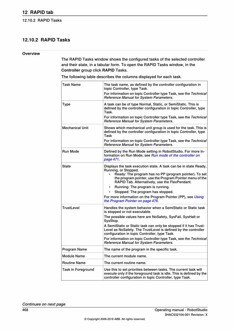
12.10.2 RAPID Tasks
OverviewThe RAPID Tasks window shows the configured tasks of the selected controllerand their state, in a tabular form. To open the RAPID Tasks window, in theController group click RAPID Tasks.The following table describes the columns displayed for each task.
The task name, as defined by the controller configuration intopic Controller, type Task.
Task Name
For information on topic Controller type Task, see the TechnicalReference Manual for System Parameters.
A task can be of type Normal, Static, or SemiStatic. This isdefined by the controller configuration in topic Controller, typeTask.
Type
For information on topic Controller type Task, see the TechnicalReference Manual for System Parameters.
Shows which mechanical unit group is used for the task. This isdefined by the controller configuration in topic Controller, typeTask
Mechanical Unit
For information on topic Controller type Task, see the TechnicalReference Manual for System Parameters.
Defined by the Run Mode setting in RobotStudio. For more in-formation on Run Mode, see Run mode of the controller onpage 471.
Run Mode
Displays the task execution state. A task can be in state Ready,Running, or Stopped.
• Ready: The program has no PP (program pointer). To setthe program pointer, use the Program Pointer menu of theRAPID Tab. Alternatively, use the FlexPendant.
• Running: The program is running.• Stopped: The program has stopped.
For more information on the Program Pointer (PP), see Usingthe Program Pointer on page 476.
State
Handles the system behavior when a SemiStatic or Static taskis stopped or not executable.
TrustLevel
The possible values here are NoSafety, SysFail, SysHalt orSysStop.A SemiStatic or Static task can only be stopped if it has Trust-Level as NoSafety. The TrustLevel is defined by the controllerconfiguration in topic Controller, type Task.For information on topic Controller type Task, see the TechnicalReference Manual for System Parameters.
The name of the program in the specific task.Program Name
The current module name.Module Name
The current routine name.Routine Name
Use this to set priorities between tasks. The current task willexecute only if the foreground task is idle. This is defined by thecontroller configuration in topic Controller, type Task.
Task in Foreground
Continues on next page468 Operating manual - RobotStudio
3HAC032104-001 Revision: X© Copyright 2008-2018 ABB. All rights reserved.
12 RAPID tab12.10.2 RAPID Tasks
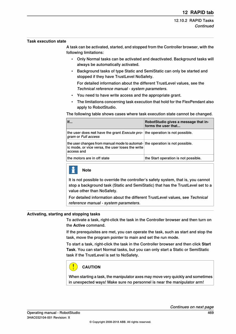
Task execution stateA task can be activated, started, and stopped from the Controller browser, with thefollowing limitations:
• Only Normal tasks can be activated and deactivated. Background tasks willalways be automatically activated.
• Background tasks of type Static and SemiStatic can only be started andstopped if they have TrustLevel NoSafety.For detailed information about the different TrustLevel values, see theTechnical reference manual - system parameters.
• You need to have write access and the appropriate grant.• The limitations concerning task execution that hold for the FlexPendant also
apply to RobotStudio.The following table shows cases where task execution state cannot be changed.
RobotStudio gives a message that in-forms the user that...
If...
the operation is not possible.the user does not have the grant Execute pro-gram or Full access
the operation is not possible.the user changes from manual mode to automat-ic mode, or vice versa, the user loses the writeaccess and
the Start operation is not possible.the motors are in off state
Note
It is not possible to override the controller’s safety system, that is, you cannotstop a background task (Static and SemiStatic) that has the TrustLevel set to avalue other than NoSafety.For detailed information about the different TrustLevel values, see Technicalreference manual - system parameters.
Activating, starting and stopping tasksTo activate a task, right-click the task in the Controller browser and then turn onthe Active command.If the prerequisites are met, you can operate the task, such as start and stop thetask, move the program pointer to main and set the run mode.To start a task, right-click the task in the Controller browser and then click StartTask. You can start Normal tasks, but you can only start a Static or SemiStatictask if the TrustLevel is set to NoSafety.
CAUTION
When starting a task, the manipulator axes may move very quickly and sometimesin unexpected ways! Make sure no personnel is near the manipulator arm!
Continues on next pageOperating manual - RobotStudio 4693HAC032104-001 Revision: X
© Copyright 2008-2018 ABB. All rights reserved.
12 RAPID tab12.10.2 RAPID Tasks
Continued
To stop a task, right-click the task in the Controller browser and then click StopTask. You can stop Normal tasks, but you can only stop a Static or SemiStatic taskif the TrustLevel is set to NoSafety.
Note
This method of starting and stopping tasks is applicable only for RobotWareversion 5.15.xx and below. For later versions of RobotWare, the method to startand stop tasks is detailed in the Test and debug group on page 475.
470 Operating manual - RobotStudio3HAC032104-001 Revision: X
© Copyright 2008-2018 ABB. All rights reserved.
12 RAPID tab12.10.2 RAPID TasksContinued
12.10.3 Run Mode
Run mode of the controllerThe Run Mode indicates the mode of the controller. It has the following two options:
• Continuous• Single
You can set the run mode of the controller in the following ways:• On the RAPID tab, in the Controller group, click Run Mode and then click
either Continuous or Single.• This method is only applicable to virtual controllers in a station.
On the Simulation tab, in the Configure group, click Simulation Setup andthen select Continuous or Single in the Setup Simulation dialog box.
Operating manual - RobotStudio 4713HAC032104-001 Revision: X
© Copyright 2008-2018 ABB. All rights reserved.
12 RAPID tab12.10.3 Run Mode
12.10.4 Adjust Robtargets
OverviewThe Adjust Robtargets feature helps in recalculating and changing the robtargetdata (tooldata and workobject data) while maintaining the joint angles of the robot.The robtarget data related to the specified source tooldata and workobject will beadjusted for usage with the new tooldata and workobject. In the RAPID tab, in theController group, click Adjust Robtargets to access this feature.
Prerequisites• You should have a controller (virtual or real) running with one or more
modules containing procedures with a sequence of move instructionsexpressed with a defined tool and workobject.
• You should have RobotStudio Premium license to use this feature.• The Execute button of the feature Adjust Robtargets will be enabled only if
the selected tool data or workobject data have the same properties, such asrobhold, ufprog, ufmec and so on.
Note
Arrays, event records, and offsets are not supported. Relative tool is also notsupported. Circular move instruction (MoveC) is supported.
Using Adjust Robtargets
Note
Take a backup copy of your modules before adjusting your robtargets.
The following procedure describes the Adjust Robtargets feature in RobotStudio:1 On the RAPID tab, in the Controller browser, select a RAPID task or module
under the RAPID icon. Then click Adjust Robtargets on the RAPID tab.Alternatively, right-click the RAPID task or module in theController browser,and then click Adjust Robtargets in the context menu.The Robtarget Adjust dialog box appears.
Note
You can accessAdjust Robtargets from theController tab also. Right-clickthe RAPID task or module in the Controller browser and then click AdjustRobtargets in the context menu.
2 If the module you want to adjust is selected, then go to Step 4. Otherwisecontinue with the next step.
Continues on next page472 Operating manual - RobotStudio
3HAC032104-001 Revision: X© Copyright 2008-2018 ABB. All rights reserved.
12 RAPID tab12.10.4 Adjust Robtargets

3 Select a task from the Task drop-down list and module from the Moduledrop-down list.
Note
In the Module drop-down list, you can either select a particular module or<ALL> to update.
4 Select the source robtarget data (that is, the data defined in the selectedtask) from Old tooldata and Old wobjdata drop-down list.
5 Select the destination robtarget data (that is, new tooldata and workobject)from New tooldata and New wobjdata drop-down list.
6 Click Execute.The Execute button is enabled only if source robtarget data (that is, oldtooldata and workobject) and destination robtarget data (that is, new tooldataand workobject) are different.
The module searches for move instructions that use the specified old tooldata orworkobject and recalculates the robtarget data for the new tooldata and workobject.For example,
1 Select "tool0" as the source tool and "wobj0" as the source workobject.2 Select "toolb" as the new tool and "wobjb"as the new workobject.3 Click Execute.
Robtargets of "tool0" and "wobj0" will be replaced with re-calculated robtargetswhich correspond to the same robot configuration (all joint angles will be the same),and with the new tool "toolb" and "wobjb". Note that both the tooldata and thewobjdata are replaced independently.
Update instructionBy default, the Update instruction check box is selected. This means that moveinstructions using the specified source (old) tooldata and workobject will be updatedto use the target (new) tooldata and workobject in addition to recalculating therobtargets.If the Update instruction check box is cleared, the robtargets will be recalculated,but the move instructions will not be updated. They will still use the source tooldataand workobject.This feature is useful after the calibration of tooldata and workobject. Aftercalibration, you might still want to use the old names of the tooldata and workobject,but update their values and recalculate the robtargets accordingly. The followingsample procedure illustrates how this can be accomplished.
Sample procedurePrerequisite: RAPID module with robtargets and move instructions that useuncalibrated tooldata tool1, and workobject wobj1.
1 Calibrate your tooldata tool1, and workobject wobj1. Store the new valuesin tool1_calib and wobj1_calib, respectively. Keep the old values of the
Continues on next pageOperating manual - RobotStudio 4733HAC032104-001 Revision: X
© Copyright 2008-2018 ABB. All rights reserved.
12 RAPID tab12.10.4 Adjust Robtargets
Continued
uncalibrated tooldata and workobject in tool1, and wobj1. An error messagegets displayed for an invalid selection of tooldata or workobject data.
2 Open the Adjust robtargets tool and clear the Update instruction check box.Select your RAPID module, enter tool1, and wobj1 as your old tooldata andwobjdata, and tool1_calib, and wobj1_calib as the new tooldata and wobjdata,respectively.
3 Click Execute, and apply the changes to the controller from the RAPID Editor4 In the RAPID Editor, rename your tooldata tool1 to tool1_uncalib, and
tool1_calib to tool1 and apply the changes to the controller. Also, performthe same for wobj1.
Now, your robtargets are updated to match the calibrated values of tool1 and wobj1.
Limitations• If a robtarget is used more than once but with different tools or workobjects,
then a message Target is referenced is displayed in the output window.• The adjust robtargets function operates on a module level and does not
update any referenced targets defined in other modules. It ignores the scopeof the robtargets when the referenced targets are local to a procedure. Inthis case, any targets with the same name in the module scope will also beupdated.
• Adjust Robtargets function works for modules with semantic errors, the editorexcludes the particular line containing the error and continues with programexecution. But Syntax errors stop program execution.
474 Operating manual - RobotStudio3HAC032104-001 Revision: X
© Copyright 2008-2018 ABB. All rights reserved.
12 RAPID tab12.10.4 Adjust RobtargetsContinued
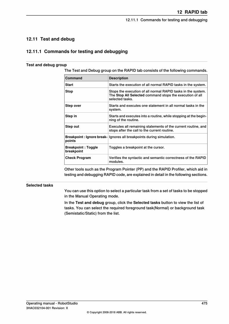
12.11 Test and debug
12.11.1 Commands for testing and debugging
Test and debug groupThe Test and Debug group on the RAPID tab consists of the following commands.
DescriptionCommand
Starts the execution of all normal RAPID tasks in the system.Start
Stops the execution of all normal RAPID tasks in the system.The Stop All Selected command stops the execution of allselected tasks.
Stop
Starts and executes one statement in all normal tasks in thesystem.
Step over
Starts and executes into a routine, while stopping at the begin-ning of the routine.
Step in
Executes all remaining statements of the current routine, andstops after the call to the current routine.
Step out
Ignores all breakpoints during simulation.Breakpoint : Ignore break-points
Toggles a breakpoint at the cursor.Breakpoint : Togglebreakpoint
Verifies the syntactic and semantic correctness of the RAPIDmodules.
Check Program
Other tools such as the Program Pointer (PP) and the RAPID Profiler, which aid intesting and debugging RAPID code, are explained in detail in the following sections.
Selected tasksYou can use this option to select a particular task from a set of tasks to be stoppedin the Manual Operating mode.In the Test and debug group, click the Selected tasks button to view the list oftasks. You can select the required foreground task(Normal) or background task(Semistatic/Static) from the list.
Operating manual - RobotStudio 4753HAC032104-001 Revision: X
© Copyright 2008-2018 ABB. All rights reserved.
12 RAPID tab12.11.1 Commands for testing and debugging

12.11.2 Using the Program Pointer
How the Program Pointer helpsDuring program execution, the Program Pointer (PP) points to the line of code thatis currently executing.The function Follow Program Pointer keeps the program pointer visible duringprogram execution by automatically scrolling the RAPID editor window accordingto the movements of the program pointer. To enable the function, in the Test andDebug group on the RAPID tab, click the arrow next to the Program Pointer iconand then select Follow Program Pointer.
Note
While the program executes, you can see the program pointer jump acrossmodules only if those modules are already open in the editor. Hence, you candecide in which modules you wish to follow the program pointer in, and keepthem open.
The other commands in the Program Pointer menu are:• Go To Program Pointer – To show the current location of the program pointer
in the RAPID editor• Go To Motion Pointer – To show the current location of the motion pointer
in the RAPID editor• To set the program pointer at a particular line code or code segment and
then start program execution from that point, use the Set Program Pointeroptions. You can choose from the following options:
- Set Program Pointer to Main in all tasks- Set Program Pointer to Cursor- Set Program Pointer to Routine
Maintaining the Program PointerThe RAPID code can only be edited when the controller is not running, that is whenit is in state Ready or Stopped. In Ready state the program pointer is not set, butin Stopped state the Program Pointer is set to a specific location of the program.For limited changes to the RAPID code of a controller in Stopped state, the currentlocation of the program pointer can be maintained. After such an edit you canresume program execution from where it was without having to reset the programpointer.
Note
If the edit is too large for the program pointer to be maintained then a warningmessage is displayed to convey this.
The program pointer cannot be maintained, for example, when editing the line ofcode at which the program pointer is located. Editing that line of code results in
Continues on next page476 Operating manual - RobotStudio
3HAC032104-001 Revision: X© Copyright 2008-2018 ABB. All rights reserved.
12 RAPID tab12.11.2 Using the Program Pointer
resetting the program pointer. In effect, the program will start from the beginningwhen the controller is started after the edit.
WARNING
Starting program execution after the program pointer has been reset will causethe robot to move along the shortest path from its current location to the firstpoint of the program.
Operating manual - RobotStudio 4773HAC032104-001 Revision: X
© Copyright 2008-2018 ABB. All rights reserved.
12 RAPID tab12.11.2 Using the Program Pointer
Continued

12.11.3 Using the RAPID Profiler
What's RAPID ProfilerThe RAPID Profiler analyzes the execution times on procedure level, identifiescritical procedures and reports these during the execution of RAPID code.
Prerequisites for using the RAPID Profiler• You should have RobotStudio Premium license to use this feature.• You should have a controller with one or more executable tasks running.• When using the RAPID Profiler with a real controller, you require more than
25 MB of free controller disk space.
Note
The RAPID Profiler will automatically stop if either of the following controllerevents is generated by the controller. This is to avoid disturbing the robotoperation.
• 20192, Disk memory low (less than 25 MB free storage left)• 20179, Diskmemory critically low (less than 10 MB free storage left, program
execution is stopped)
How to use the RAPID ProfilerTo use the RAPID Profiler:
1 Set the Program Pointer at a desired point in the RAPID code from whereyou wish to start your analysis. For example, set the program pointer to Mainin all tasks.
2 On the RAPID tab, in the Test and Debug group, click the arrow next to theRAPID Profiler icon and then click Start.
3 Start the simulation.In the background the RAPID Spy feature logs the data about the program’sexecution.
4 After the program execution ends, click the arrow next to the RAPID Profilericon and then click Stop.
5 On the RAPID tab, in the Test and Debug group, click the arrow next to theRAPID Profiler icon and then click Analyze.The RAPID Profiler window appears, showing the results of the analysis.
Click Export to Excel to export the results to a Microsoft Excel spreadsheet file.To view the log file of the analysis, click the arrow next to the RAPID Profiler iconand then click Open log file.
Execution of the Rapid Profiler based on RobotWare versionDepending on the RobotWare version, the RAPID Profiler is executed in one of thefollowing methods:
• For controller systems with RobotWare versions prior to 5.14, the RAPIDinstructions SpyStart and SpyStop must be inserted at the RAPID execution
Continues on next page478 Operating manual - RobotStudio
3HAC032104-001 Revision: X© Copyright 2008-2018 ABB. All rights reserved.
12 RAPID tab12.11.3 Using the RAPID Profiler
start and end, respectively. When the program is run, a Spy log file isgenerated. You can open the file for analysis by the RAPID Profiler. Use theRAPID Profiler menu option Browse for Spy log to open the log file.For more information about Spy instructions, see Technical referencemanual- RAPID Instructions, Functions and Data types.
Note
When the RAPID Profiler is used to analyze a log file, there is no informationabout in which procedure the SpyStart command is executed. The triggeringprocedure defaults to <SpyStart Procedure>.
• For RobotWare version 5.14 or later, the log file can be generatedautomatically. Activate the RAPID Profiler and run the program of thecontroller. When the program execution stops, the results are presented tothe user.
Limitations• The Spy function, which produces the input to the RAPID Profiler, does not
produce useful output for systems based for Continuous Application Platform(CAP), Arc and RW Cutting. This affects the RAPID Profiler that analyses thelog that Spy function generates.
• The RAPID Spy function measures RAPID program execution time and notmotion execution time. To make these two times coincide for the RAPIDprocedures, ensure that the last move instruction of all procedures is a stoppoint. Otherwise, the RAPID instruction execution time will be lower than themotion execution time. The reason being the program execution runs aheadof the motion execution unless the programmed point is a stop point. Formore information on stop points, see RAPID Reference Manual.
Operating manual - RobotStudio 4793HAC032104-001 Revision: X
© Copyright 2008-2018 ABB. All rights reserved.
12 RAPID tab12.11.3 Using the RAPID Profiler
Continued
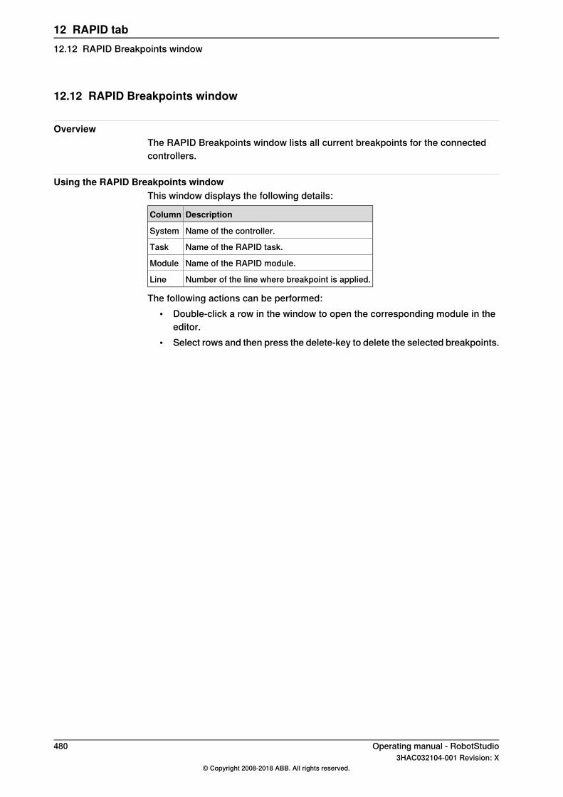
12.12 RAPID Breakpoints window
OverviewThe RAPID Breakpoints window lists all current breakpoints for the connectedcontrollers.
Using the RAPID Breakpoints windowThis window displays the following details:
DescriptionColumn
Name of the controller.System
Name of the RAPID task.Task
Name of the RAPID module.Module
Number of the line where breakpoint is applied.Line
The following actions can be performed:• Double-click a row in the window to open the corresponding module in the
editor.• Select rows and then press the delete-key to delete the selected breakpoints.
480 Operating manual - RobotStudio3HAC032104-001 Revision: X
© Copyright 2008-2018 ABB. All rights reserved.
12 RAPID tab12.12 RAPID Breakpoints window
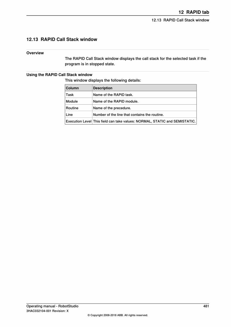
12.13 RAPID Call Stack window
OverviewThe RAPID Call Stack window displays the call stack for the selected task if theprogram is in stopped state.
Using the RAPID Call Stack windowThis window displays the following details:
DescriptionColumn
Name of the RAPID task.Task
Name of the RAPID module.Module
Name of the precedure.Routine
Number of the line that contains the routine.Line
This field can take values: NORMAL, STATIC and SEMISTATIC.Execution Level
Operating manual - RobotStudio 4813HAC032104-001 Revision: X
© Copyright 2008-2018 ABB. All rights reserved.
12 RAPID tab12.13 RAPID Call Stack window

12.14 RAPID Watch window
Viewing variables and I/O signalsThe RAPID Watch window displays the following details of selected variables andI/O signals during program execution.
DescriptionColumn
Displays variable nameName
Displays variable valueValue
Displays type of datatypeType
Displays system nameSource
You can view and edit the RAPID data of the variables in the RAPID watch window,both during program execution and when the controller is stopped. However, youcan only view, but not edit, I/O signals in the watch window.To view a variable or I/O signal in the RAPID Watch window, you need to first addit to the window. In the RAPID editor, right-click the required variable or I/O signal,and then click Add Watch.By default, during program execution the values of the variables are automaticallyrefreshed in the watch window every 2 seconds. You can also manually refreshthe values.To enable or disable automatic refresh, in the context menu, select or clear theAuto Refresh command.To do a manual refresh, in the context menu, clickRefresh (keyboard shortcut F5).
Note
CONST variables cannot be edited.On closing RobotStudio, the variables and signals added to the watch windoware removed.
On the RAPID Watch window, right-click to display the following context menu:
Used forItem
Copying the valueCopy
Pasting the copied valuePaste
Deleting the watch itemDelete
Selecting all the itemsSelect All
Clearing all the variables and signals from the watch windowClear All
Manually updating the values of the variables and signalsRefresh
Automatically refreshing the values displayed in the watchwindow at regular intervals
Auto Refresh
482 Operating manual - RobotStudio3HAC032104-001 Revision: X
© Copyright 2008-2018 ABB. All rights reserved.
12 RAPID tab12.14 RAPID Watch window
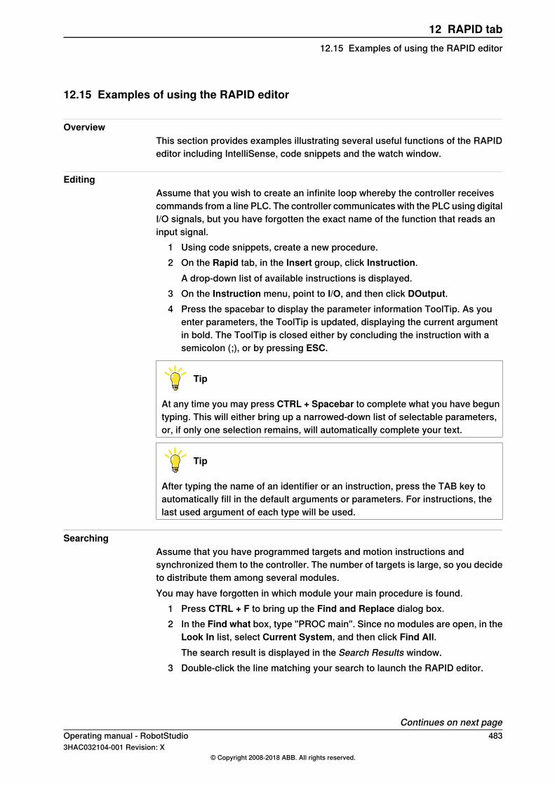
12.15 Examples of using the RAPID editor
OverviewThis section provides examples illustrating several useful functions of the RAPIDeditor including IntelliSense, code snippets and the watch window.
EditingAssume that you wish to create an infinite loop whereby the controller receivescommands from a line PLC. The controller communicates with the PLC using digitalI/O signals, but you have forgotten the exact name of the function that reads aninput signal.
1 Using code snippets, create a new procedure.2 On the Rapid tab, in the Insert group, click Instruction.
A drop-down list of available instructions is displayed.3 On the Instruction menu, point to I/O, and then click DOutput.4 Press the spacebar to display the parameter information ToolTip. As you
enter parameters, the ToolTip is updated, displaying the current argumentin bold. The ToolTip is closed either by concluding the instruction with asemicolon (;), or by pressing ESC.
Tip
At any time you may press CTRL + Spacebar to complete what you have beguntyping. This will either bring up a narrowed-down list of selectable parameters,or, if only one selection remains, will automatically complete your text.
Tip
After typing the name of an identifier or an instruction, press the TAB key toautomatically fill in the default arguments or parameters. For instructions, thelast used argument of each type will be used.
SearchingAssume that you have programmed targets and motion instructions andsynchronized them to the controller. The number of targets is large, so you decideto distribute them among several modules.You may have forgotten in which module your main procedure is found.
1 Press CTRL + F to bring up the Find and Replace dialog box.2 In the Find what box, type "PROC main". Since no modules are open, in the
Look In list, select Current System, and then click Find All.The search result is displayed in the Search Results window.
3 Double-click the line matching your search to launch the RAPID editor.
Continues on next pageOperating manual - RobotStudio 4833HAC032104-001 Revision: X
© Copyright 2008-2018 ABB. All rights reserved.
12 RAPID tab12.15 Examples of using the RAPID editor

Adding breakpointsNow that you have finished editing, you may want to test your loop and add somebreakpoints.
1 Place the insertion on the new statement and press F9 to set a breakpoint.2 Ensure that the Ignore breakpoints button in the editor toolbar is not clicked,
and click the Play button on the Simulation toolbar.The program will run and then stop at the breakpoint.
3 To run the program statement by statement, click the Step over button inthe editor toolbar.
ExecutingYou might want to debug your loop or monitor a specific variable.
1 In the RAPID editor browser, right-click the procedure you want to set asentry point, and then click Set Program Pointer to Routine.
2 In the RAPID tab, click the Play button.The program will run and then stop at the next breakpoint.
3 Select a variable for monitoring and drag it to the watch window.4 Restart the loop and monitor the variable at each iteration.
484 Operating manual - RobotStudio3HAC032104-001 Revision: X
© Copyright 2008-2018 ABB. All rights reserved.
12 RAPID tab12.15 Examples of using the RAPID editorContinued
13 Add-Ins tabOverview of the Add-Ins tab
The Add-Ins tab contains the control for PowerPacs, Migration tools and GearboxHeat Prediction. The Add-Ins browser shows the installed PowerPacs, Generaladd-ins.For instruction on building General add-ins visit the ABB Robotics Developer Centerweb site at http://developercenter.robotstudio.com.General add-ins are loaded from the following folder on your PC: C:\ProgramFiles (x86)\Common Files\ABB Industrial
IT\RoboticsIT\RobotStudio\Addins
Note
For RobotStudio 64-bit edition:• Add-ins will be loaded from the following folder: C:\Program Files
(x86)\ABB Industrial IT\RoboticsIT\RobotStudio
6.04\Bin64\Addins.
This is the path on a PC with Microsoft Windows 7, 64-bit English versionon default installation. For customized installations and for operating systemversions in other languages, this path may differ.
Continues on next pageOperating manual - RobotStudio 4853HAC032104-001 Revision: X
© Copyright 2008-2018 ABB. All rights reserved.
13 Add-Ins tab

13.1 RobotApps
You can view and download RobotWare, RobotWare Add-in and RobotStudioAdd-ins from the RobotApps window. This window is divided into two panes, Thenames of all add-ins appear on one pane and the details of the selected folder aredisplayed on the other pane. You can download a specific version of the add-infrom this pane. You can also view and download contents from the ABB RobotAppsweb page.
Continues on next page486 Operating manual - RobotStudio
3HAC032104-001 Revision: X© Copyright 2008-2018 ABB. All rights reserved.
13 Add-Ins tab13.1 RobotApps

13.1.1 Distribution package
OverviewA distribution package may consist of one or more products. When distributed asone file, the suffix of the file is .rspak. Use the Install Package command in theRobotApps page to install a distribution package.RobotWare Add-In for the StandAlone Controller (SAC) is a separate package.This package is available in the RobotApps page in the Add-Ins tab. You caninstall RobotWare Add-Ins by browsing to a RobotWare Add-In manifest (.rmf file).The Add-Ins browser shows the installed packages.
Locations of distribution packageIn RobotStudio 6, RobotWare and related packages are referred as applicationdata. A distribution package is available in the following locations.
• ProgramData: used when the appdata is shared among users on thecomputer. If RobotWare is installed with RobotStudio, the path is%ProgramData%\ABB Industrial IT\Robotics IT\DistributionPackages\ andon a PC with a default installation of Windows 7, the path isC:\ProgramData\ABB Industrial IT\Robotics IT\DistributionPackages.
• LocalAppData: used if a package or manifest is installed by a particular user.If RobotWare is installed with RobotStudio, the path is Users\<username>\AppData\Local\ABB Industrial IT\Robotics IT\DistributionPackagesand on a PC with a default installation of Windows 7, the path isC:\Users\<user name>\AppData\Local\ABB Industrial IT\Robotics IT\DistributionPackages.
• Customized location (optional): may be used when several users share apackage repository. For more information, see Additional distributionpackage location in RobotStudio Options:General:Files & Folders.
Note
In the RobotApps page, in the Add-Ins browser, when you hover the mousepointer over a package node, the tooltip displays the location information of aspecific package. Right-click an installed package and then click Open PackageFolder to view the location of the selected package folder.
Continues on next pageOperating manual - RobotStudio 4873HAC032104-001 Revision: X
© Copyright 2008-2018 ABB. All rights reserved.
13 Add-Ins tab13.1.1 Distribution package
Unpacked dataWhen used by a virtual controller, the packages are unpacked into a cached locationresiding in a LocalAppData sub-folder, Users\<user name>\AppData\Local\ABBIndustrial IT\Robotics IT\RobotWare. On a PC with a default installation of Windows7, the path is C:\Users\<user name>\AppData\Local\ABB Industrial IT\RoboticsIT\RobotWare. The content of this folder is similar to the RobotWare 5 Mediapoolfolder.
Note
Add-ins will be used from the same location, till the virtual controller refers tothat location. It can be used by more than one system.If a new version of RobotWare is installed to the same location, the add-ins willbe overwritten.
Note
To uninstall a distribution package, right-click the particular package and thenclick Uninstall Package. This removes the selected package and related,unpacked data.
488 Operating manual - RobotStudio3HAC032104-001 Revision: X
© Copyright 2008-2018 ABB. All rights reserved.
13 Add-Ins tab13.1.1 Distribution packageContinued
13.2 Migration tools
OverviewTo migrate a robot system from RobotWare 5 to RobotWare 6 you need to use themigration tools in the Add-ins tab.If you are upgrading from RobotWare version 5.15 or earlier, you must contactABB to replace the controller main computer by DSQC 1000 and also to get aRobotWare 6 license. You can contact your ABB Robotics Service representativeat www.abb.com/contacts.For details on the migration process, refer Instruction - RobotWare upgrade andmigration guide.
Operating manual - RobotStudio 4893HAC032104-001 Revision: X
© Copyright 2008-2018 ABB. All rights reserved.
13 Add-Ins tab13.2 Migration tools
13.3 Gearbox Heat Prediction
OverviewThe Gearbox Heat Prediction Tool is an add-in for RobotStudio which helps topredict heat problems in the gearboxes. When the temperature is above apredefined value, you can adjust the cycle to reduce the temperature or order afan that can cool down the gear.Robots with compact gearboxes have a risk of getting overheated under certaincircumstances. The gearbox temperature is supervised by Service InformationSystem (SIS). SIS is a software function within the robot controller, that simplifiesmaintenance of the robot system. It supervises the operating time and mode ofthe robot, and alerts the operator when a maintenance activity is scheduled. It alsosupervises large robots from damaging the motors during high load operationswith a safety shutdown.The temperature supervision is based on an algorithm that predicts the stationarytemperature of the gearboxes and motors of the robot. The algorithm predicts theheat based on the character of the robot motion and also the room temperature.Intensive motion (high average speed and /or high average torque and/or shortwait time) will increase the heat of the gearbox and motors.To avoid overheating, SIS stops the robot if the temperature becomes too high.For large robots, there is an option to add a cooling fan to axis 1, 2, and sometimesaxis 3, to allow the robot to run even with a heavy duty program.
Note
Gearbox Heat Prediction is not supported for Tool and External axis. When avirtual controller has more than one robot, only one robot will have predictionscalculated. The other robots will only display 0% chance of overheating.
Prerequisites1 RobotStudio 5.14.02 or later.2 RobotWare 5.14.01 or later.3 RobotStudio station with controller having a programmed cycle that includes
payload for the robot.
Calculating the Gearbox HeatUse the following procedure for predicting the heat generated by the robot:
1 Create a new station or open a saved station. The Gearbox heat button isnow visible in the Add-Ins tab.
2 In theAdd-Ins tab, click Gearbox Heat. TheGearbox Heat Predictionwindowopens.
Continues on next page490 Operating manual - RobotStudio
3HAC032104-001 Revision: X© Copyright 2008-2018 ABB. All rights reserved.
13 Add-Ins tab13.3 Gearbox Heat Prediction
3 In the Add-Ins tab, select Enabled to enable the Gearbox Heat Predictiontool .
Note
For a manipulator without compact gear, Gearbox Heat Prediction isdisabled.
4 Run a simulation.
Note
For RobotStudio Basic, the Play button in the Simulation tab will bedisabled. As such, you will be unable to run the simulation from theSimulation tab. In such a scenario, use the Play button which will now bevisible in the Gearbox Heat Prediction tab window to run the simulation.
Note
The data is recorded during the simulation only if the Gearbox Heat toolis enabled. After the recording is finished, you can perform anotherrecording or perform a calculation for heat related problems.
5 In Cycles, define the behavior of the cycle for predicting the heat generatedby the robot:
• Continuous: Select this option if you want the robot to continuouslycalculate the predictions without waiting time between two consecutivecycles.
• Number of cycles per hour: Select this option if you want to manuallyspecify the number of cycles per hour for calculation.
• Waiting time between cycles (sec): Select this option to specify thewaiting between cycles. Specify the waiting time in seconds.
6 In Ambient Temperature, define the ambient temperature.• Use the slider to change the temperature.• Select Use temperature from controller(s) to reset the the ambient
temperature.
Note
The ambient temperature used in the calculations should be the samethat is used in the configuration of the actual robot in its realenvironment.
7 Calculate the result in either of the following ways:• In the Recordings section, either double-click a recording or select a
recording and click Calculate.
Continues on next pageOperating manual - RobotStudio 4913HAC032104-001 Revision: X
© Copyright 2008-2018 ABB. All rights reserved.
13 Add-Ins tab13.3 Gearbox Heat Prediction
Continued

• In the System section, either double-click a controller or select acontroller and click Calculate.
Note
- The Recordings section displays the recordings to be analyzedwhen Gearbox Heat Prediction is enabled.
- The System section displays all the available controllers. Datafor all controllers are recorded at all times and you can selectthe controller to be analysed from the list.
The results are displayed for each joint and with fans for the joints thatcan have fans installed as an option.
Note
The following factors influence the heat accumulated:- Axis speed- Payload- Room temperature (ambient temperature)- Waiting time (to allow robot to cool down)
Note
The calculated energy is displayed as different heat levels:- Green: Indicates no heat problem- Orange: Indicates it is recommended to install a fan.- Red: Indicates a fan must be installed.- Grey: Indicates it is not possible to calculate the possible energy
level for this joint.- Not available: Indicates the joints that cannot have a fan
installed.
Note
Recommended action is displayed along with the warning level foreach joint.
- Joint: Represents the joint.- Without fan: Displays the percentage of heat levels calculated
to the corresponding joint without fan.- With fan: Displays the percentage of heat levels calculated to
the corresponding joint with fan.- Action: Displays the recommended action.
492 Operating manual - RobotStudio3HAC032104-001 Revision: X
© Copyright 2008-2018 ABB. All rights reserved.
13 Add-Ins tab13.3 Gearbox Heat PredictionContinued

14 Context menus14.1 Add to Path
Creating a move instruction based on an existing target1 Select the target for which to create the move instruction.2 From the Home menu, in the Path Programming group, select the type of
move instruction to create.3 Click Add to Path.
The move instruction will appear under the path node as a reference to theoriginal target.
Operating manual - RobotStudio 4933HAC032104-001 Revision: X
© Copyright 2008-2018 ABB. All rights reserved.
14 Context menus14.1 Add to Path
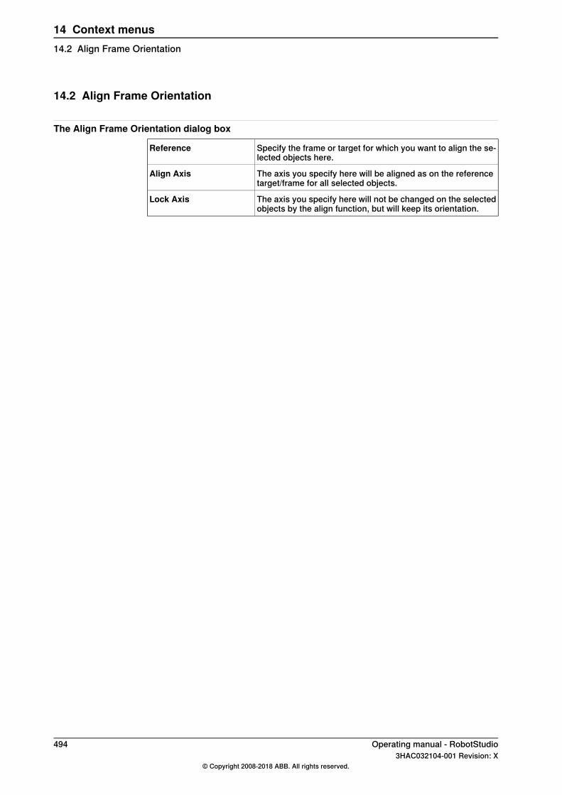
14.2 Align Frame Orientation
The Align Frame Orientation dialog box
Specify the frame or target for which you want to align the se-lected objects here.
Reference
The axis you specify here will be aligned as on the referencetarget/frame for all selected objects.
Align Axis
The axis you specify here will not be changed on the selectedobjects by the align function, but will keep its orientation.
Lock Axis
494 Operating manual - RobotStudio3HAC032104-001 Revision: X
© Copyright 2008-2018 ABB. All rights reserved.
14 Context menus14.2 Align Frame Orientation
14.3 Align Target Orientation
Aligning target orientation1 Select the targets whose orientation you wish to change.2 Click Align Target Orientation to bring up a dialog box.3 In the Reference box, specify the target whose orientation you want to use
as reference, by first click in the box and then selecting the target either fromthe graphics view or the Layout browser.
4 In the Align Axis box, select the axis whose orientation you want to copyfrom the reference target to the selected ones.
5 In the Lock Axis box, select the axis to rotate the target around. Theorientation of this axis will not be changed on the targets. For example, if theZ axis of all targets are orientated normally to the surface of the work pieceand you want to keep it this way, you should lock the Z axis.
6 Click Apply.
Tip
You can change the Align and Lock axis and click Apply again to reorientate thetargets until you deselect them.
Operating manual - RobotStudio 4953HAC032104-001 Revision: X
© Copyright 2008-2018 ABB. All rights reserved.
14 Context menus14.3 Align Target Orientation
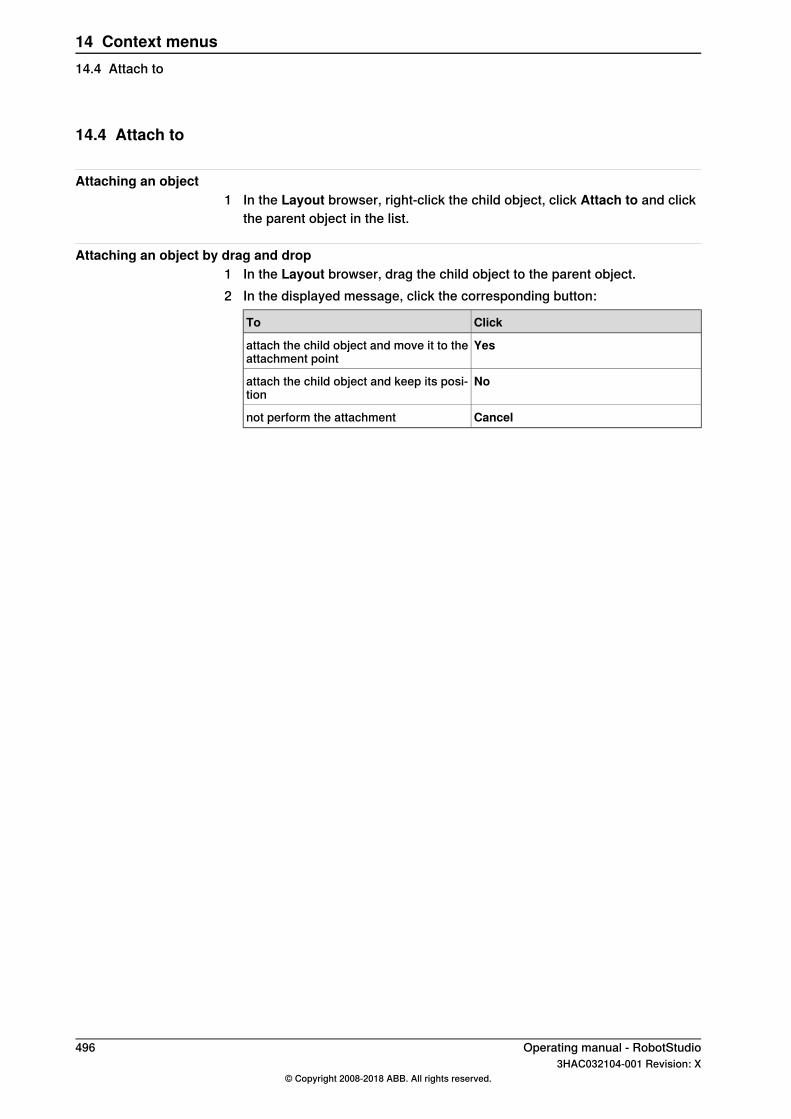
14.4 Attach to
Attaching an object1 In the Layout browser, right-click the child object, click Attach to and click
the parent object in the list.
Attaching an object by drag and drop1 In the Layout browser, drag the child object to the parent object.2 In the displayed message, click the corresponding button:
ClickTo
Yesattach the child object and move it to theattachment point
Noattach the child object and keep its posi-tion
Cancelnot perform the attachment
496 Operating manual - RobotStudio3HAC032104-001 Revision: X
© Copyright 2008-2018 ABB. All rights reserved.
14 Context menus14.4 Attach to
14.5 Configurations
Auto ConfigurationThe Auto Configuration function runs through the path and optimizes theconfigurations with respect to their preceding targets. Joint move instructions areaffected, if theAll move instructions option is selected. If the Linear/circular moveinstructions option is selected, linear and circular motion is affected but joint moveinstructions are not affected.In the Paths&Targets browser, right-click a path, select Configurations and thenselect Auto Configuration.The robot now steps through each target in the path and sets the configurations.
Verify ConfigurationsThe Verify configuration function runs through the path and check if the targetsare reachable with the specified configurations. Use the following procedure forverifying the existing configuration:In the Paths&Targets browser, right-click a path, select Configurations and thenselect Verify Configurations.
Auto Configuration for a dual-arm robotA normal robot arm has six axis or degrees of freedom of movement whereas adual-arm robot has seven degrees of movement. Hence by configuring its armangles, a dual-arm robot can adapt several ways to reach a target. You can set thearm angle while applying auto configuration.
Operating manual - RobotStudio 4973HAC032104-001 Revision: X
© Copyright 2008-2018 ABB. All rights reserved.
14 Context menus14.5 Configurations
14.6 Configurations
Manually setting a robot axis configuration for single targets1 In the Paths&Targets browser, select a target and then clickConfigurations
to bring up a dialog box.2 If more than one configuration solution exist, examine them by clicking them,
one at a time.The position of the robot with the selected configuration will be displayed inthe graphics window, and the joint values for the configuration will bedisplayed in the joint values list below the configurations list.In most cases, selecting a configuration similar to the previous one is thebest choice.
3 Select the configuration to use and click Apply.
498 Operating manual - RobotStudio3HAC032104-001 Revision: X
© Copyright 2008-2018 ABB. All rights reserved.
14 Context menus14.6 Configurations
14.7 Convert Frame to Workobject
Converting a frame to a workobject1 In the Layout browser, select a frame.2 Click Convert Frame to Workobject. The new workobject will appear in the
Paths&Targets browser.3 Optionally, rename or edit the workobject in any way.
Operating manual - RobotStudio 4993HAC032104-001 Revision: X
© Copyright 2008-2018 ABB. All rights reserved.
14 Context menus14.7 Convert Frame to Workobject
14.8 Work envelope
OverviewThe defined area of space through which a robot can move. A robot can onlyperform within the confines of this work envelope.
Viewing the work envelope of a robot1 In the Layout browser, right-click any robot.2 From the context menu, select Show Work Envelope, the work envelope
options are displayed on the left hand pane.3 Select the object and the required view, for example, Robot Wrist/Active
Tool and 3D Volume/2D Outline. The corresponding work envelope getsdisplayed.
500 Operating manual - RobotStudio3HAC032104-001 Revision: X
© Copyright 2008-2018 ABB. All rights reserved.
14 Context menus14.8 Work envelope
14.9 Convert to Move Circular
PrerequisitesAt least two targets, the via-point target and the end point target, must have beencreated.A path containing at least the via-point target and the end point target, in correctorder, must have been created.
Converting to Move Circular1 In the Paths&Targets browser, expand the path node that contains the move
instruction to be converted.2 Select the move instruction that contains the via-point of the circular motion
together with the succeeding move instruction, which will serve as the endpoint. You can select several instructions by holding down the SHIFT keywhile clicking the instructions.
3 Click Convert to Move Circular. The two selected move instructions will beconverted to a circular move instruction, which includes the via-point andthe end point.
Tip
To convert two move instructions to a circular motion, you can also select andright-click both move instructions at once and then click Convert to Circular.
Operating manual - RobotStudio 5013HAC032104-001 Revision: X
© Copyright 2008-2018 ABB. All rights reserved.
14 Context menus14.9 Convert to Move Circular
14.10 Copy / Apply Orientation
Copying and applying an orientation1 In the browser, select the object or target from which to copy the orientation.2 On the Modify menu, click Copy Orientation.3 In the browser, select the object or target to which to apply the orientation.4 On the Modify menu, click Apply Orientation. This can be performed on
several targets or a group of selected targets.
502 Operating manual - RobotStudio3HAC032104-001 Revision: X
© Copyright 2008-2018 ABB. All rights reserved.
14 Context menus14.10 Copy / Apply Orientation

14.11 Detach
Detaching an object1 In the Layout browser, right-click the attached object (child) and then click
Detach. The child will be detached from the parent and return to its positionbefore the attachment.
Operating manual - RobotStudio 5033HAC032104-001 Revision: X
© Copyright 2008-2018 ABB. All rights reserved.
14 Context menus14.11 Detach
14.12 Defeature
OverviewDefeature identifies and removes certain features from a 3D model. It simplifiesthe model by removing unnecessary details and provides a flexible interface withfeature recognition parameters defining the desired level of detail. The defeaturefunction works on fillets, chamfers, and round holes.Use the Defeature function to recognize and remove the following features:
• Holes: Cylindrical, conical, spherical, and toroidal holes are supported. Holesbelow the specified radius will be recognized.
• Chamfers: Chamfers are straight-line transitions between surfaces. If theun-chamfered intersection of the adjoining faces would otherwise form aright angle, then the chamfer will typically be uniform and pitched at 45°.Chamfers below the specified width will be recognized.
• Blends: Blends are smooth transitions with continuity matching betweensurfaces. Constant radius and variable radius blends are supported. Blendsbelow the specified radius will be recognized.
Note
All the previewed features cannot be removed by RobotStudio
Prerequisite• Part must contain CAD geometry (SAT, STEP or similar) and not only the
graphical data (STL, VRML, or similar).• Part must be imported into the station.
Defeaturing a 3D model1 In the Layout browser, right-click the model.2 Click Modify and then from the context menu, click Defeature.
The Defeature dialog box appears.3 Specify the parameters to define the desired level of detail. The recognized
features can be viewed through the Preview function.4 Click Apply.
Small features and unnecessary details are removed based on the definedparameters.
504 Operating manual - RobotStudio3HAC032104-001 Revision: X
© Copyright 2008-2018 ABB. All rights reserved.
14 Context menus14.12 Defeature
14.13 Execute Move Instruction
PrerequisitesThe move instruction must exist.A virtual controller must be running for the robot with the move instruction.
Executing a move instruction1 In the Paths&Targets browser, browse to the motion instruction to execute
through the Controller, Tasks and Paths nodes.2 Click Execute move instruction. The TCP of the active robot will move from
the current location to the motion instruction according to the programedmotion properties. If the target for the motion instruction does not have astored configuration, the robot will use the configuration nearest the currentone.
Operating manual - RobotStudio 5053HAC032104-001 Revision: X
© Copyright 2008-2018 ABB. All rights reserved.
14 Context menus14.13 Execute Move Instruction
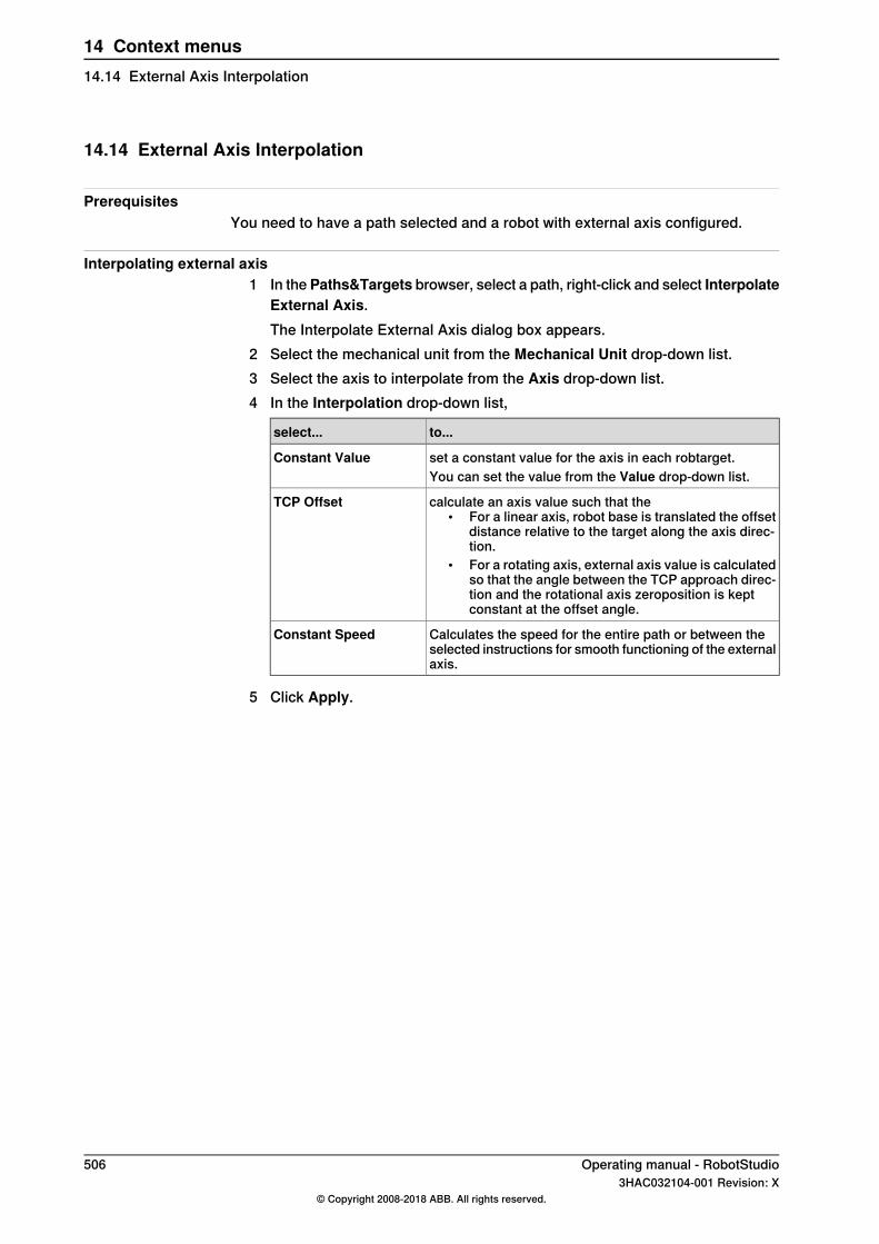
14.14 External Axis Interpolation
PrerequisitesYou need to have a path selected and a robot with external axis configured.
Interpolating external axis1 In thePaths&Targets browser, select a path, right-click and select Interpolate
External Axis.The Interpolate External Axis dialog box appears.
2 Select the mechanical unit from the Mechanical Unit drop-down list.3 Select the axis to interpolate from the Axis drop-down list.4 In the Interpolation drop-down list,
to...select...
set a constant value for the axis in each robtarget.Constant ValueYou can set the value from the Value drop-down list.
calculate an axis value such that the• For a linear axis, robot base is translated the offset
distance relative to the target along the axis direc-tion.
• For a rotating axis, external axis value is calculatedso that the angle between the TCP approach direc-tion and the rotational axis zeroposition is keptconstant at the offset angle.
TCP Offset
Calculates the speed for the entire path or between theselected instructions for smooth functioning of the externalaxis.
Constant Speed
5 Click Apply.
506 Operating manual - RobotStudio3HAC032104-001 Revision: X
© Copyright 2008-2018 ABB. All rights reserved.
14 Context menus14.14 External Axis Interpolation
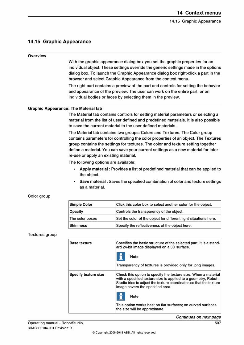
14.15 Graphic Appearance
OverviewWith the graphic appearance dialog box you set the graphic properties for anindividual object. These settings override the generic settings made in the optionsdialog box. To launch the Graphic Appearance dialog box right-click a part in thebrowser and select Graphic Appearance from the context menu.The right part contains a preview of the part and controls for setting the behaviorand appearance of the preview. The user can work on the entire part, or onindividual bodies or faces by selecting them in the preview.
Graphic Appearance: The Material tabThe Material tab contains controls for setting material parameters or selecting amaterial from the list of user defined and predefined materials. It is also possibleto save the current material to the user defined materials.The Material tab contains two groups: Colors and Textures. The Color groupcontains parameters for controlling the color properties of an object. The Texturesgroup contains the settings for textures. The color and texture setting togetherdefine a material. You can save your current settings as a new material for laterre-use or apply an existing material.The following options are available:
• Apply material : Provides a list of predefined material that can be applied tothe object.
• Savematerial : Saves the specified combination of color and texture settingsas a material.
Color group
Click this color box to select another color for the object.Simple Color
Controls the transparency of the object.Opacity
Set the color of the object for different light situations here.The color boxes
Specify the reflectiveness of the object here.Shininess
Textures group
Specifies the basic structure of the selected part. It is a stand-ard 24-bit image displayed on a 3D surface.
Note
Transparency of textures is provided only for .png images.
Base texture
Check this option to specify the texture size. When a materialwith a specified texture size is applied to a geometry, Robot-Studio tries to adjust the texture coordinates so that the textureimage covers the specified area.
Note
This option works best on flat surfaces; on curved surfacesthe size will be approximate.
Specify texture size
Continues on next pageOperating manual - RobotStudio 5073HAC032104-001 Revision: X
© Copyright 2008-2018 ABB. All rights reserved.
14 Context menus14.15 Graphic Appearance

Specifies how the texture is combined with the specified objectcolor.
Blend Mode
Provides a highly reflective appearance to the surface.Environment map
Specifies a texture that defines the bumpiness of the surfaceNormal Map
Graphic Appearance: The Properties tabThe Properties tab contains controls for surface properties and texture coordinates.
Surface Properties
By selecting this option surfaces will be rendered regardlessof orientation.
Render both sides
Selected surfaces can be inverted by this button.Invert surface(s)This process is simplified by checkingHighlight inverted faces,which will cause the background of surfaces to be displayedin red.
Generate new normals. If the surface normals of an importedgeometry are of poor quality, they can be recreated by clickingthis button.
Generate new normals
Texture coordinates
Click this button to swap the horizontal and vertical directionsof the texture.
Swap u/v
Select along which directions the commands listed below shallbe applied.
Modify
u is the horizontal axis of the texture.v is the vertical axis of the texture.
Click this button to set the ratio between the dimensions of theobject and the texture to 1.
Normalize
Click this button to invert the coordinates along the selectedaxes. This is the same as mirroring around the other axis.
Flip
Click this button to stretch the texture along the selected axes.Stretch
Click this button to shrink the texture along the selected axes.Shrink
Click this button to move the texture along the selected axes.Shift<
Click this button to move the texture along the selected axes.Shift>
508 Operating manual - RobotStudio3HAC032104-001 Revision: X
© Copyright 2008-2018 ABB. All rights reserved.
14 Context menus14.15 Graphic AppearanceContinued
14.16 Remove internal geometry
OverviewThis function reduces the model by removing bodies and faces that are not visiblefrom outside. Internal bodies will be removed completely while internal faces willbe removed from the graphical representation. To restore the faces, the graphicalrepresentation must be created.
Removing the internal geometry1 In the Layout browser, right-click the model.2 Click Modify and then from the context menu, click Remove internal
geometry.Bodies and faces that are not visible from outside will be removed.
Operating manual - RobotStudio 5093HAC032104-001 Revision: X
© Copyright 2008-2018 ABB. All rights reserved.
14 Context menus14.16 Remove internal geometry
14.17 Go to Visualization and Go to Declaration
Go to VisualizationThe Go to visualization context menu command is available for targets in theRAPID editor. It takes you to the 3D graphical widow to show you where the targetis found.
Note
This command requires that the RAPID code has been synchronized to thestation.
Go to DeclarationIn the Paths & Targets browser, the Go To Declaration context menu commandis available for targets. This command takes you back to the target in the RAPIDeditor.
Note
This command requires that the RAPID code has been synchronized to the virtualcontroller.
510 Operating manual - RobotStudio3HAC032104-001 Revision: X
© Copyright 2008-2018 ABB. All rights reserved.
14 Context menus14.17 Go to Visualization and Go to Declaration
14.18 Zone visualization
The function shows a circle at each target, that represents the TCP zone of theprogrammed zone data. To access this function right-click Path and then selectView and then click Show Zones.Commands
Shows a circle of the same radius as the minimum of the zone size the usersets or a zone with radius half the distance to the preceding or succeedingtarget in the path. This corresponds to the zone reduction carried out by thecontroller during program execution.
Show Zones
Depending on the zone data the circle takes different colors white, red, and purple.• White: The default color• Red: If the zone data contains the preceding or subsequent target, that is, if
the zone data is larger than the closest distance.• Purple: If the zone data is greater than half the distance to the preceding or
subsequent target.
Note
True move will not work for a user defined customized zone.
Operating manual - RobotStudio 5113HAC032104-001 Revision: X
© Copyright 2008-2018 ABB. All rights reserved.
14 Context menus14.18 Zone visualization

14.19 Zone reduction
The zone size cannot be larger than half the distance to the preceding or succeedingtarget in the path. If a larger zone is specified, the robot automatically reduces it.The zonedata of zones that are red or purple when visualized with Show Zonesare replaced by the largest possible standard zone data, for example, if the largestpossible zone is 123 mm, then the zonedata is replaced by z100.To reduce zone size, follow these steps:
1 In the Paths&Targets browser or the graphics window, select the path.2 Right-click and select Path and then select Reduce zones to access this
option.
512 Operating manual - RobotStudio3HAC032104-001 Revision: X
© Copyright 2008-2018 ABB. All rights reserved.
14 Context menus14.19 Zone reduction

14.20 Interpolate Path
Reorienting targets in a path by interpolation1 In the Layout browser or the graphics window, select the path with the targets
to reorient.2 Click Interpolate Path. to bring up a dialog box.3 With the Interpolate type options, select whether to use Linear or Absolute
interpolation.Linear interpolation distributes the difference in orientation evenly, basedon the targets positions along the length of the path. By contrast, absoluteinterpolation distributes the difference in orientation evenly, based on thetargets’ sequence in the path.
4 If using the Select Start/End option, select the start and end targets for theinterpolation in the Start target and End target boxes, respectively.
5 Optionally, with the Lock Axis options, select an axis to lock.6 Click Apply.
Operating manual - RobotStudio 5133HAC032104-001 Revision: X
© Copyright 2008-2018 ABB. All rights reserved.
14 Context menus14.20 Interpolate Path
14.21 Invert
Inverting the direction of a face1 In the Layout browser, click the arrow on the upper right corner and then
selectShow Bodies and Show Faces/Curves.2 Expand Part and Body nodes to see the faces.3 Right-click a face and then click Invert.
If the option backface culling is activated, then the face will shift from visibleto invisible, or vice versa, depending on the direction you view the face from.If backface culling is deactivated, then there will be no visible indication thatthe direction of the face has been inverted.
514 Operating manual - RobotStudio3HAC032104-001 Revision: X
© Copyright 2008-2018 ABB. All rights reserved.
14 Context menus14.21 Invert
14.22 Jump to Target
Jumping to a target1 In the Paths&Targets browser, browse to the target to jump to through the
Controller, Tasks and WorkObjects nodes.2 Click Jump to target.
If the target has a valid configuration for the robot axes stored, the activeTCP of the robot will immediately be positioned at the target. If no validconfiguration is stored, the Select Robot configuration dialog box isdisplayed.
3 In the Select Robot Configuration dialog box, select a suitable configurationsolution and click Apply. The selected configuration is now stored with thetarget.
Note
You can deactivate the configuration check when jumping to targets. The robotwill then use the configuration solution closest to the current one when reachingthe target. For more information, see Options on page 218.
Operating manual - RobotStudio 5153HAC032104-001 Revision: X
© Copyright 2008-2018 ABB. All rights reserved.
14 Context menus14.22 Jump to Target

14.23 Linked Geometry
OverviewThe Linked Geometry feature allows you to load geometry from a shared repository.If the source file is updated, then the station will be updated with a single click.
Adding LinkYou can add a link to a geometry in two ways:
1 In the Home tab, click Import Geometry to open a dialog box.Select the option Link to Geometry.
2 In the Layout browser, right-click an existing part in the station and selectAdd Link.A dialog box opens where you can select the CAD file to be linked.
Editing LinkTo edit an existing link:
1 In the Layout browser, right-click an existing part in the station.2 Select the option Link to Geometry and click Edit Link.
Deleting LinkTo delete an existing link:
1 In the Layout browser, right-click an existing part in the station.2 Select the option Link to Geometry and click Delete Link.
Updating Linked GeometryTo update a linked geometry:
1 In the Layout browser, right-click an existing part in the station, componentgroup or the station.
2 Select the option Link to Geometry and click Update Linked Geometry.The update result is displayed in the output window.
Note
When you select a component group or a station, all linked geometrieswithin the group or station is updated. If the timestamp on the file is newerthan the timestamp stored in the station, all corresponding parts will beupdated from the source location.
516 Operating manual - RobotStudio3HAC032104-001 Revision: X
© Copyright 2008-2018 ABB. All rights reserved.
14 Context menus14.23 Linked Geometry

14.24 Modify Library Component
Modifying a library component1 In the Layout browser, select the library you wish to modify.2 Click Disconnect Library.3 Select the library and then make any modifications to it.4 Select the modified library, and then click Save As Library.
Operating manual - RobotStudio 5173HAC032104-001 Revision: X
© Copyright 2008-2018 ABB. All rights reserved.
14 Context menus14.24 Modify Library Component
14.25 Mechanism Joint Jog
Jogging the joints of a robot1 In the Layout browser, select the robot.2 Click Mechanism Joint Jog to bring up a dialog box.3 Each row in the Jog Joints dialog box represents a joint of the robot. Jog
the joints either by clicking and dragging the bar at each row, or by using thearrows to the right of each row.Set the length of each step in the Step box.
The Mechanism Joint Jog dialog box
Move the joints of the objects by dragging the slider on the rowcorresponding to each joint. Alternatively, click the buttons tothe right of the row, or type a value.
Joint
The current configuration value.Cfg
The current position of the TCP.TCP
Specify the length of the joint movements for each click of thebuttons to the right of each joint row.
Step
If the robot uses external axes, you can select an axis to jogfrom this list. The external axes must belong to the same taskas the object you are jogging for occurring in this list. If no ex-ternal axes are present in the same task, this list is not avail-able.
External Axis
Select this check box to reposition the robot according to thejogging of the external axis.
Lock TCP
For track-external axes the robot will reposition so that the TCPis locked relative to the world coordinate system.For positioner-external axes the robot will reposition so thatthe position of the robot’s TCP is locked relative to the attach-ment point of the positioner. The robot will move with the posi-tioner the same way as when using multi-robot jog.If no external axes are present in the same task, this checkbox is not available.
Move the joint of the external axes by dragging the slider onthe row corresponding to each joint. Alternatively, click thebuttons to the right of the row, or type a value.
External axes joint
If no external axes are present in the same task, this checkbox is not available.
Jogging a conveyor
Note
Using the following step, you can attach a workobject to the conveyor:Click Workpiece source, right-click the part and then select Attach Workobjectand then click workobject.
1 In the Layout browser, click the Conveyor node.2 Right-click Conveyor and then select Conveyor Jog.
The Conveyor Jog tab opens.
Continues on next page518 Operating manual - RobotStudio
3HAC032104-001 Revision: X© Copyright 2008-2018 ABB. All rights reserved.
14 Context menus14.25 Mechanism Joint Jog

3 In the Conveyor Jog tab, click Connection and attached Workobject.4 Move the slider to jog the conveyor.
Operating manual - RobotStudio 5193HAC032104-001 Revision: X
© Copyright 2008-2018 ABB. All rights reserved.
14 Context menus14.25 Mechanism Joint Jog
Continued

14.26 Mechanism Linear Jog
Jogging the TCP of a robot by using the Linear Jog dialog box1 In the Layout browser, select the robot.2 Click Mechanism Linear Jog to bring up a dialog box.3 Each row in the Linear Jog dialog box represents a direction or rotation for
the TCP. Jog the TCP along the preferred direction or rotation, either byclicking and dragging the bar at each row, or by using the arrows to the rightof each row.
4 From the Reference list, you can select the coordinate system that you wantto jog the robot relative to.
5 In the Step box, specify the step movement per deg/rad.
520 Operating manual - RobotStudio3HAC032104-001 Revision: X
© Copyright 2008-2018 ABB. All rights reserved.
14 Context menus14.26 Mechanism Linear Jog
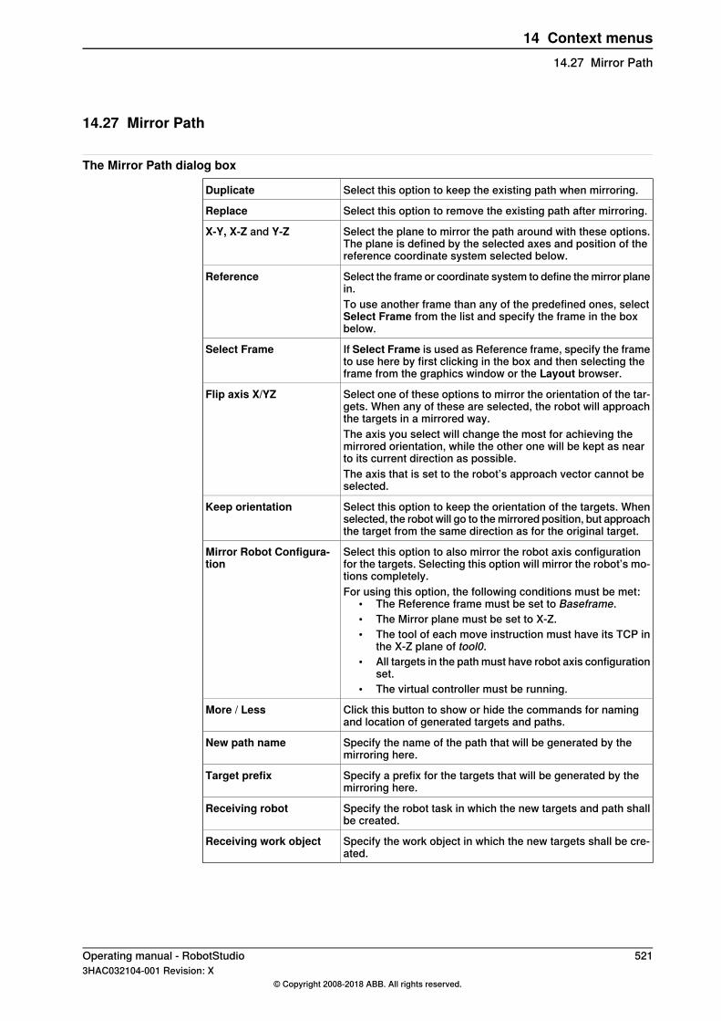
14.27 Mirror Path
The Mirror Path dialog box
Select this option to keep the existing path when mirroring.Duplicate
Select this option to remove the existing path after mirroring.Replace
Select the plane to mirror the path around with these options.The plane is defined by the selected axes and position of thereference coordinate system selected below.
X-Y, X-Z and Y-Z
Select the frame or coordinate system to define the mirror planein.
Reference
To use another frame than any of the predefined ones, selectSelect Frame from the list and specify the frame in the boxbelow.
If Select Frame is used as Reference frame, specify the frameto use here by first clicking in the box and then selecting theframe from the graphics window or the Layout browser.
Select Frame
Select one of these options to mirror the orientation of the tar-gets. When any of these are selected, the robot will approachthe targets in a mirrored way.
Flip axis X/YZ
The axis you select will change the most for achieving themirrored orientation, while the other one will be kept as nearto its current direction as possible.The axis that is set to the robot’s approach vector cannot beselected.
Select this option to keep the orientation of the targets. Whenselected, the robot will go to the mirrored position, but approachthe target from the same direction as for the original target.
Keep orientation
Select this option to also mirror the robot axis configurationfor the targets. Selecting this option will mirror the robot’s mo-tions completely.
Mirror Robot Configura-tion
For using this option, the following conditions must be met:• The Reference frame must be set to Baseframe.• The Mirror plane must be set to X-Z.• The tool of each move instruction must have its TCP in
the X-Z plane of tool0.• All targets in the path must have robot axis configuration
set.• The virtual controller must be running.
Click this button to show or hide the commands for namingand location of generated targets and paths.
More / Less
Specify the name of the path that will be generated by themirroring here.
New path name
Specify a prefix for the targets that will be generated by themirroring here.
Target prefix
Specify the robot task in which the new targets and path shallbe created.
Receiving robot
Specify the work object in which the new targets shall be cre-ated.
Receiving work object
Operating manual - RobotStudio 5213HAC032104-001 Revision: X
© Copyright 2008-2018 ABB. All rights reserved.
14 Context menus14.27 Mirror Path
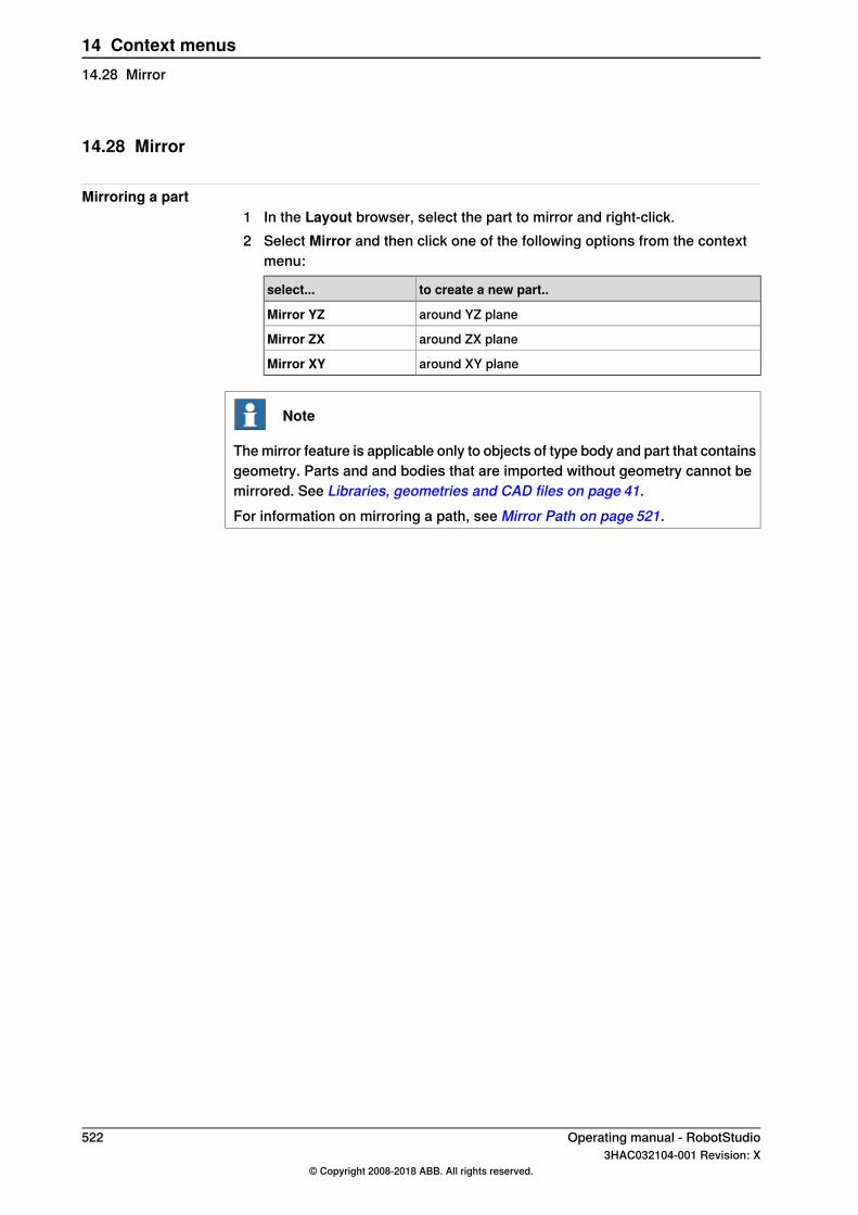
14.28 Mirror
Mirroring a part1 In the Layout browser, select the part to mirror and right-click.2 Select Mirror and then click one of the following options from the context
menu:
to create a new part..select...
around YZ planeMirror YZ
around ZX planeMirror ZX
around XY planeMirror XY
Note
The mirror feature is applicable only to objects of type body and part that containsgeometry. Parts and and bodies that are imported without geometry cannot bemirrored. See Libraries, geometries and CAD files on page 41.For information on mirroring a path, see Mirror Path on page 521.
522 Operating manual - RobotStudio3HAC032104-001 Revision: X
© Copyright 2008-2018 ABB. All rights reserved.
14 Context menus14.28 Mirror
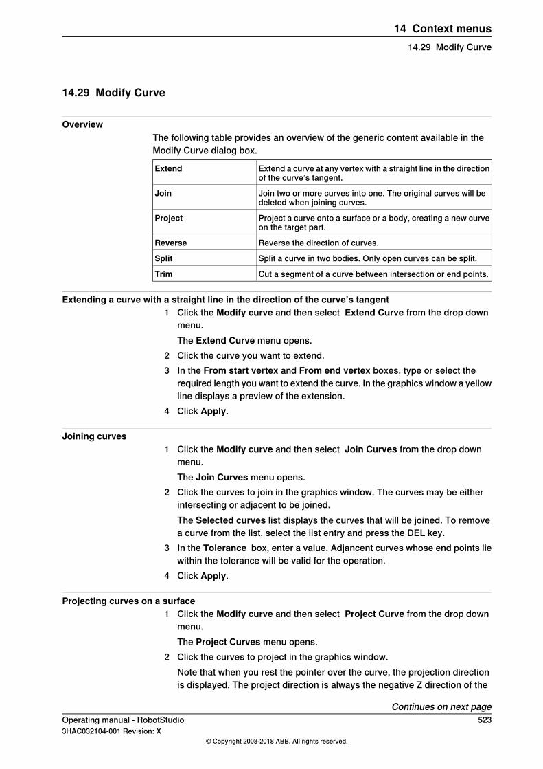
14.29 Modify Curve
OverviewThe following table provides an overview of the generic content available in theModify Curve dialog box.
Extend a curve at any vertex with a straight line in the directionof the curve’s tangent.
Extend
Join two or more curves into one. The original curves will bedeleted when joining curves.
Join
Project a curve onto a surface or a body, creating a new curveon the target part.
Project
Reverse the direction of curves.Reverse
Split a curve in two bodies. Only open curves can be split.Split
Cut a segment of a curve between intersection or end points.Trim
Extending a curve with a straight line in the direction of the curve’s tangent1 Click the Modify curve and then select Extend Curve from the drop down
menu.The Extend Curve menu opens.
2 Click the curve you want to extend.3 In the From start vertex and From end vertex boxes, type or select the
required length you want to extend the curve. In the graphics window a yellowline displays a preview of the extension.
4 Click Apply.
Joining curves1 Click the Modify curve and then select Join Curves from the drop down
menu.The Join Curves menu opens.
2 Click the curves to join in the graphics window. The curves may be eitherintersecting or adjacent to be joined.The Selected curves list displays the curves that will be joined. To removea curve from the list, select the list entry and press the DEL key.
3 In the Tolerance box, enter a value. Adjancent curves whose end points liewithin the tolerance will be valid for the operation.
4 Click Apply.
Projecting curves on a surface1 Click the Modify curve and then select Project Curve from the drop down
menu.The Project Curves menu opens.
2 Click the curves to project in the graphics window.Note that when you rest the pointer over the curve, the projection directionis displayed. The project direction is always the negative Z direction of the
Continues on next pageOperating manual - RobotStudio 5233HAC032104-001 Revision: X
© Copyright 2008-2018 ABB. All rights reserved.
14 Context menus14.29 Modify Curve

User Coordinate System. To change the projection direction, create a newframe with the desired orientation and set it as user coordinate system.The Selected curves list displays the curves that will be projected. To removea curve from the list, select the list entry and press the DEL key.
3 Click in the Target bodies list and then click the bodies to project on in thegraphics window. The bodies must be in the projection direction and be bigenough to cover the projected curves.To remove a bodies from the list, select the list entry and press the DEL key.
4 Click Apply. A new curve will now be created in a new part, wrapped aroundthe surface of the selected bodies.
Reversing curves1 Click the Modify Curve and then select Reverse Curve from the drop down
menu.The Project Curves menu opens.
2 Click the curves to reverse in the graphics window.Note that when you rest the pointer over a curve, the current direction of thecurve is displayed by yellow arrows.The Selected curves list displays the curves that will be reversed. To removea curve from the list, select the list entry and press the DEL key.
3 Click Apply. The curves will now be reversed.
Splitting a curve1 Click the Modify Curve and then select Split Curve from the menu to open
the tool.2 Click the curve at the point to split at. Only open curves can be split.
Note that when you rest the pointer over the curve, point of the split ishighlighted. This point is affected by the current snap mode setting.
3 Click Apply. The curve will now be split to two separate curves in the samepart.
Trimming a curve1 Click the Modify Curve and then select Trim Curve in the menu to open the
tool.2 Click the curve segment to trim.
Trim only works on single curves with intersection points. If you want to trima curve that intersects with another curve, first join the two curves.
3 Click Apply. The selected part of the curve will now be removed.
524 Operating manual - RobotStudio3HAC032104-001 Revision: X
© Copyright 2008-2018 ABB. All rights reserved.
14 Context menus14.29 Modify CurveContinued
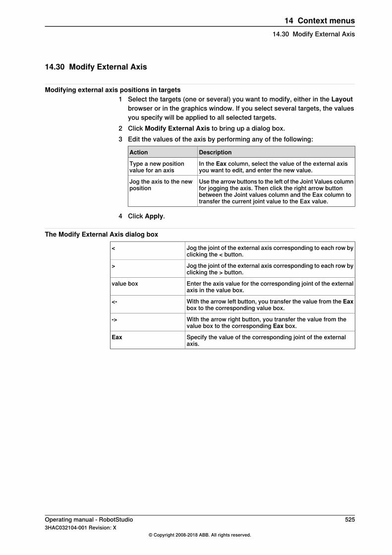
14.30 Modify External Axis
Modifying external axis positions in targets1 Select the targets (one or several) you want to modify, either in the Layout
browser or in the graphics window. If you select several targets, the valuesyou specify will be applied to all selected targets.
2 Click Modify External Axis to bring up a dialog box.3 Edit the values of the axis by performing any of the following:
DescriptionAction
In the Eax column, select the value of the external axisyou want to edit, and enter the new value.
Type a new positionvalue for an axis
Use the arrow buttons to the left of the Joint Values columnfor jogging the axis. Then click the right arrow buttonbetween the Joint values column and the Eax column totransfer the current joint value to the Eax value.
Jog the axis to the newposition
4 Click Apply.
The Modify External Axis dialog box
Jog the joint of the external axis corresponding to each row byclicking the < button.
<
Jog the joint of the external axis corresponding to each row byclicking the > button.
>
Enter the axis value for the corresponding joint of the externalaxis in the value box.
value box
With the arrow left button, you transfer the value from the Eaxbox to the corresponding value box.
<-
With the arrow right button, you transfer the value from thevalue box to the corresponding Eax box.
->
Specify the value of the corresponding joint of the externalaxis.
Eax
Operating manual - RobotStudio 5253HAC032104-001 Revision: X
© Copyright 2008-2018 ABB. All rights reserved.
14 Context menus14.30 Modify External Axis
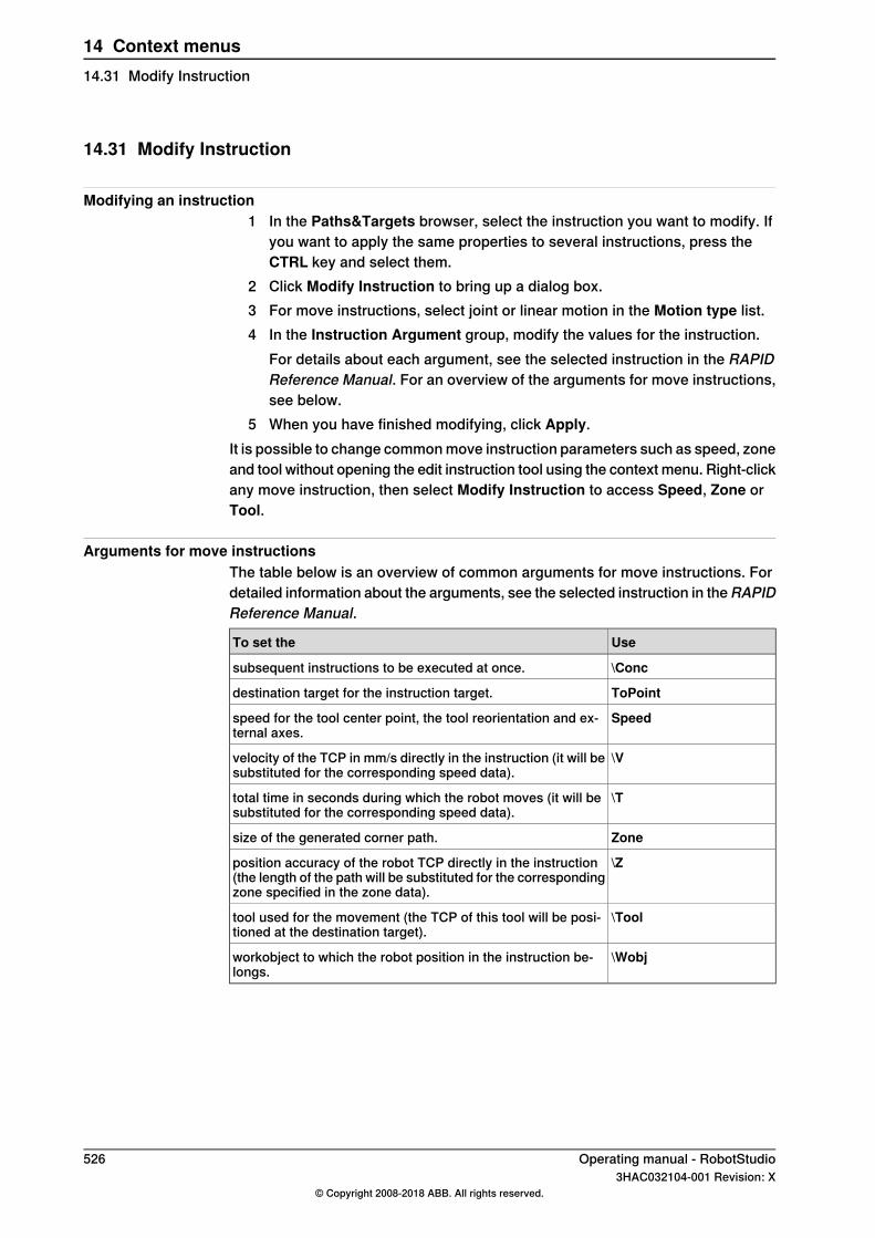
14.31 Modify Instruction
Modifying an instruction1 In the Paths&Targets browser, select the instruction you want to modify. If
you want to apply the same properties to several instructions, press theCTRL key and select them.
2 Click Modify Instruction to bring up a dialog box.3 For move instructions, select joint or linear motion in the Motion type list.4 In the Instruction Argument group, modify the values for the instruction.
For details about each argument, see the selected instruction in the RAPIDReference Manual. For an overview of the arguments for move instructions,see below.
5 When you have finished modifying, click Apply.It is possible to change common move instruction parameters such as speed, zoneand tool without opening the edit instruction tool using the context menu. Right-clickany move instruction, then select Modify Instruction to access Speed, Zone orTool.
Arguments for move instructionsThe table below is an overview of common arguments for move instructions. Fordetailed information about the arguments, see the selected instruction in theRAPIDReference Manual.
UseTo set the
\Concsubsequent instructions to be executed at once.
ToPointdestination target for the instruction target.
Speedspeed for the tool center point, the tool reorientation and ex-ternal axes.
\Vvelocity of the TCP in mm/s directly in the instruction (it will besubstituted for the corresponding speed data).
\Ttotal time in seconds during which the robot moves (it will besubstituted for the corresponding speed data).
Zonesize of the generated corner path.
\Zposition accuracy of the robot TCP directly in the instruction(the length of the path will be substituted for the correspondingzone specified in the zone data).
\Tooltool used for the movement (the TCP of this tool will be posi-tioned at the destination target).
\Wobjworkobject to which the robot position in the instruction be-longs.
526 Operating manual - RobotStudio3HAC032104-001 Revision: X
© Copyright 2008-2018 ABB. All rights reserved.
14 Context menus14.31 Modify Instruction
14.32 Modify Mechanism
The Modify Mechanism dialog boxSee The Modify Mechanism dialog box on page 349.
Operating manual - RobotStudio 5273HAC032104-001 Revision: X
© Copyright 2008-2018 ABB. All rights reserved.
14 Context menus14.32 Modify Mechanism
14.33 Modify Tooldata
Modifying tooldata1 In the Layout browser, select the tooldata you want to modify.2 Click Modify Tooldata to bring up a dialog box.3 In the Misc Data group:
• Modify the Name of the tool.• Select if the tool is to be held by the robot in the Robot holds tool list.
4 In the Tool Frame group:• Modify the Position x, y, z of the tool.• Modify the Rotation rx, ry, rz of the tool.
5 In the Load Data group:• Enter a new Weight for the tool.• Modify the Center of gravity for the tool.• Modify the Inertia for the tool.
6 In the Sync Properties group:• In the Storage type list, select PERS or TASK PERS. Select TASK
PERS if you intend to use the tooldata in MultiMove mode.• In the Module list, modify the module in which to declare the tooldata.
7 Click Apply.
528 Operating manual - RobotStudio3HAC032104-001 Revision: X
© Copyright 2008-2018 ABB. All rights reserved.
14 Context menus14.33 Modify Tooldata
14.34 Modify Workobject
Modifying a workobject1 In the Layout browser, select the workobject you want to modify.2 Click Modify Workobject. to bring up a dialog box.3 In the Misc Data group, modify the values for the workobject:
• Enter a Name for the workobject.• In the Robot holds workobject list, select True or False. If you select
True, the robot will move the work piece instead of the tool.• In the Moved by mechanical unit list, select the mechanical unit with
which the robot movements are coordinated. This setting is only validwhen Programmed has been set to False.
• In the Programmed list, select True or False. True means that theworkobject will use a fixed coordinate system, and False that a movablecoordinate system (that is, coordinated external axes) will be used.
4 In the User Frame group, do one of the following:• Modify the user frame by entering values for the Position x, y, z and
the Rotation rx, ry, rz for the workobject. Click in one of these boxes,and then click the position in the graphics window to transfer the values.
• Modify the user frame by using the Frame by points dialog box, seeFrame from Three Points on page 239 .
5 In the Object Frame group, do one of the following:• Modify the object frame by selecting values for Position x, y, z and
Rotation rx, ry, rz for the workobject.• Modify the object frame by using the Frame by points dialog box.
6 In the Sync Properties group, modify the values for the workobject:• In the Storage type list, select PERS or TASK PERS. Select TASK
PERS if you intend to use the workobject in MultiMove mode.• In theModule list, select the module in which to declare the workobject.
7 Click Apply.
Note
If you change the position of a workobject that is used in a program, you haveto synchronize the affected paths to the virtual controller; otherwise, the programwill not be updated.
Operating manual - RobotStudio 5293HAC032104-001 Revision: X
© Copyright 2008-2018 ABB. All rights reserved.
14 Context menus14.34 Modify Workobject
14.35 Move Along Path
PrerequisitesAt least one path must have been created in the station.A virtual controller must be running for the robot to move along the path.
Moving along a path1 In the Paths&Targets browser, select the path to move along.2 Click Move along path. In the graphics window, the robot will move along
the path.
530 Operating manual - RobotStudio3HAC032104-001 Revision: X
© Copyright 2008-2018 ABB. All rights reserved.
14 Context menus14.35 Move Along Path
14.36 Move to Pose
PrerequisitesAt least one joint position must be defined.Only one mechanism may be selected at a time.
Moving to a pose1 In the Layout browser, select one mechanism to move.2 ClickMove to Pose and then click one of the available poses. In the graphics
window, the mechanism will move to the pose.
Operating manual - RobotStudio 5313HAC032104-001 Revision: X
© Copyright 2008-2018 ABB. All rights reserved.
14 Context menus14.36 Move to Pose
14.37 Offset Position
Offset the position an item1 Right-click the item you want to move.2 Click Offset Position to bring up the Offset Position dialog box.3 In the dialog box, select the reference coordinate system you want to use:
SelectIf you want to move the item
Localrelative to its own coordinate system
Parentrelative to the coordinate system of itsparent
Worldrelative to the coordinate system of thestation
UCSrelative to a user-defined coordinate sys-tem
Target Reference Framerelative to a target reference frameThis option is available only for targets.
4 In the Translation X, Y, Z boxes, either type the offset, or select it by firstclicking in one of the value boxes and then clicking the point in the graphicswindow.
5 Specify the Rotation for the item.6 Click Apply.
532 Operating manual - RobotStudio3HAC032104-001 Revision: X
© Copyright 2008-2018 ABB. All rights reserved.
14 Context menus14.37 Offset Position
14.38 Place
Placing an item1 Select the item you want move.2 Click Place and then click one of the commands to bring up a dialog box.
ChooseIf you want to move the item
One Pointfrom one position to another without af-fecting the orientation of the object.Select the axes to be affected.
Two Pointsaccording to the relationship between astart and a finish line.The object will move to match the firstpoint, then it will rotate to match thesecond point.
Three Pointsaccording to the relationship between astart plane and a finish plane.The object will move to match the firstpoint, then it will rotate to match the thirdpoint.
Framefrom one position to a target or frameposition and simultaneously change theorientation of the object according to theframe orientation.The position of the object changes accord-ing the orientation of the to-point coordin-ate system.
Two Framesfrom one frame of reference to another
3 Set the reference coordinate system you want to use.4 Click the points in the graphics window to transfer values to the from-point
boxes to the to-point boxes. For detailed information, see the tables below.5 Click Apply.
The Place Object by One Point dialog box
Select the reference coordinate system to which all positionsor points will be related.
Reference
Click in one of these boxes, and then click the primary pointin the graphics window to transfer the values to the PrimaryPoint - From boxes.
Primary Point - From
Click in one of these boxes, and then click the primary pointin the graphics window to transfer the values to the PrimaryPoint - To boxes.
Primary Point - To
Select whether the translation is to be performed along the X,Y or Z axis, or several of the axes.
Translate along theseaxes
The Place Object by Two Points dialog box
Select the reference coordinate system to which all positionsor points will be related.
Reference
Continues on next pageOperating manual - RobotStudio 5333HAC032104-001 Revision: X
© Copyright 2008-2018 ABB. All rights reserved.
14 Context menus14.38 Place

Click in one of these boxes, and then click the primary pointin the graphics window to transfer the values to the PrimaryPoint - From boxes.
Primary Point - From
Click in one of these boxes, and then click the primary pointin the graphics window to transfer the values to the PrimaryPoint - To boxes.
Primary Point - To
Click in one of these boxes, and then click the point on the xaxis in the graphics window to transfer the values to the Pointon X-Axis - From boxes.
Point on X-Axis - From
Click in one of these boxes, and then click the point on the xaxis in the graphics window to transfer the values to the Pointon X-Axis - To boxes.
Point on X-Axis - To
Select whether the translation is to be performed along the X,Y or Z axis, or several of the axes.
Translate along theseaxes
The Place an Object by Three Points dialog box
Select the reference coordinate system to which all positionsor points will be related.
Reference
Click in one of these boxes, and then click the primary pointin the graphics window to transfer the values to the PrimaryPoint - From boxes.
Primary Point - From
Click in one of these boxes, and then click the primary pointin the graphics window to transfer the values to the PrimaryPoint - To boxes.
Primary Point - To
Click in one of these boxes, and then click the point on the xaxis in the graphics window to transfer the values to the Pointon X-Axis - From boxes.
Point on X-Axis - From
Click in one of these boxes, and then click the point on the xaxis in the graphics window to transfer the values to the Pointon X-Axis - To boxes.
Point on X-Axis - To
Click in one of these boxes, and then click the point on the yaxis in the graphics window to transfer the values to the Pointon Y-Axis - From boxes.
Point on Y-Axis - From
Click in one of these boxes, and then click the point on the yaxis in the graphics window to transfer the values to the Pointon Y-Axis - To boxes.
Point on Y-Axis - To
Select whether the translation is to be performed along the X,Y or Z axis, or several of the axes.
Translate along theseaxes
The Place Object with Frame dialog box
Specify the name of the frame with which you want to placethe object.
Select Frame
The Place by Two Frames dialog box
Select the frame object (For example, Target, Workobject,Tooldata or Frame) from this dropdown list to set the Frompoint of moving the object.
From
Select any of the frame object (For example, Target, Workob-ject, Tooldata or Frame) from this dropdown list to set the Topoint of moving the object.
To
534 Operating manual - RobotStudio3HAC032104-001 Revision: X
© Copyright 2008-2018 ABB. All rights reserved.
14 Context menus14.38 PlaceContinued
14.39 Protected Smart Component
You can protect a Smart Component from being edited. To protect the smartcomponent, right-click the smart component, and then click Protected. You canalso optionally specify a password that will be required to unlock the componentfor edits.For more information on protected smart components, see Protecting a SmartComponent from edits in the section Smart Component on page 288.
Note
Protecting a Smart Component in this manner is a way of hiding complexity, andis not for providing security or securely protecting it.
Operating manual - RobotStudio 5353HAC032104-001 Revision: X
© Copyright 2008-2018 ABB. All rights reserved.
14 Context menus14.39 Protected Smart Component

14.40 Remove Unused Targets
Removing unused targets1 In the Paths&Targets browser, select either the Controller node or the Task
node from which you wish to remove the unused targets, and then clickRemove Unused Targets.
2 To the questionAre you sure you want to remove unused targets?, answerYes. All targets that not are used by any move instructions are now removed.
536 Operating manual - RobotStudio3HAC032104-001 Revision: X
© Copyright 2008-2018 ABB. All rights reserved.
14 Context menus14.40 Remove Unused Targets
14.41 Rename Targets
Renaming targets1 In the Paths & Targets browser, select the targets to rename.
To rename all targets in one or several paths, select the paths that containthe targets.
2 Click Rename targets to bring up a dialog box.3 In the Target Prefix box, enter a text string to precede the target numbers.4 Optionally, in the Increment box and the Start with box, change the
numbering series for the target names.5 Optionally, in the Target Suffix box, enter a text string to follow the target
numbers.6 Click Apply.
Operating manual - RobotStudio 5373HAC032104-001 Revision: X
© Copyright 2008-2018 ABB. All rights reserved.
14 Context menus14.41 Rename Targets
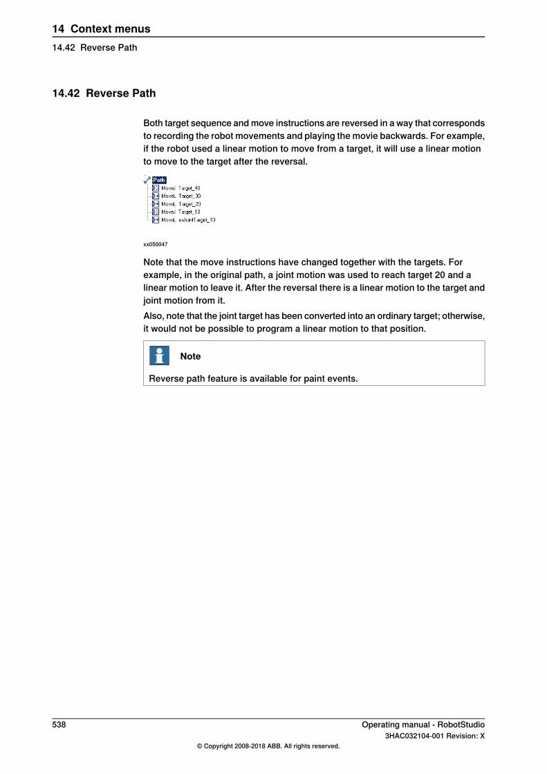
14.42 Reverse Path
Both target sequence and move instructions are reversed in a way that correspondsto recording the robot movements and playing the movie backwards. For example,if the robot used a linear motion to move from a target, it will use a linear motionto move to the target after the reversal.
xx050047
Note that the move instructions have changed together with the targets. Forexample, in the original path, a joint motion was used to reach target 20 and alinear motion to leave it. After the reversal there is a linear motion to the target andjoint motion from it.Also, note that the joint target has been converted into an ordinary target; otherwise,it would not be possible to program a linear motion to that position.
Note
Reverse path feature is available for paint events.
538 Operating manual - RobotStudio3HAC032104-001 Revision: X
© Copyright 2008-2018 ABB. All rights reserved.
14 Context menus14.42 Reverse Path
14.43 Rotate
Rotating an item1 Select the item you want to rotate.2 Click Rotate to bring up a dialog box.3 Select the reference coordinate system you want to use:
SelectIf you want to move the item
Worldabsolute in the coordinate system of thestation
Parentrelative to the coordinate system of itsparent
Localrelative to its own coordinate system
UCSrelative to the user-defined system
User defined axisrelative to an axis defined by two points
Target Reference Framerelative to a target reference frameNote that this option is available only fortargets.
4 Specify the rotation of the item in the Rotate around x, y, z by first clickingin one of the boxes, and then click the center position in the graphics windowto transfer the values.
5 If you have selected the coordinate system User defined axis, specify theAxis start point x, y, z and the Axis end point x, y, z.
6 Specify the Rotation of the item and the axis around which the rotation is tooccur.
7 Click Apply.
Operating manual - RobotStudio 5393HAC032104-001 Revision: X
© Copyright 2008-2018 ABB. All rights reserved.
14 Context menus14.43 Rotate
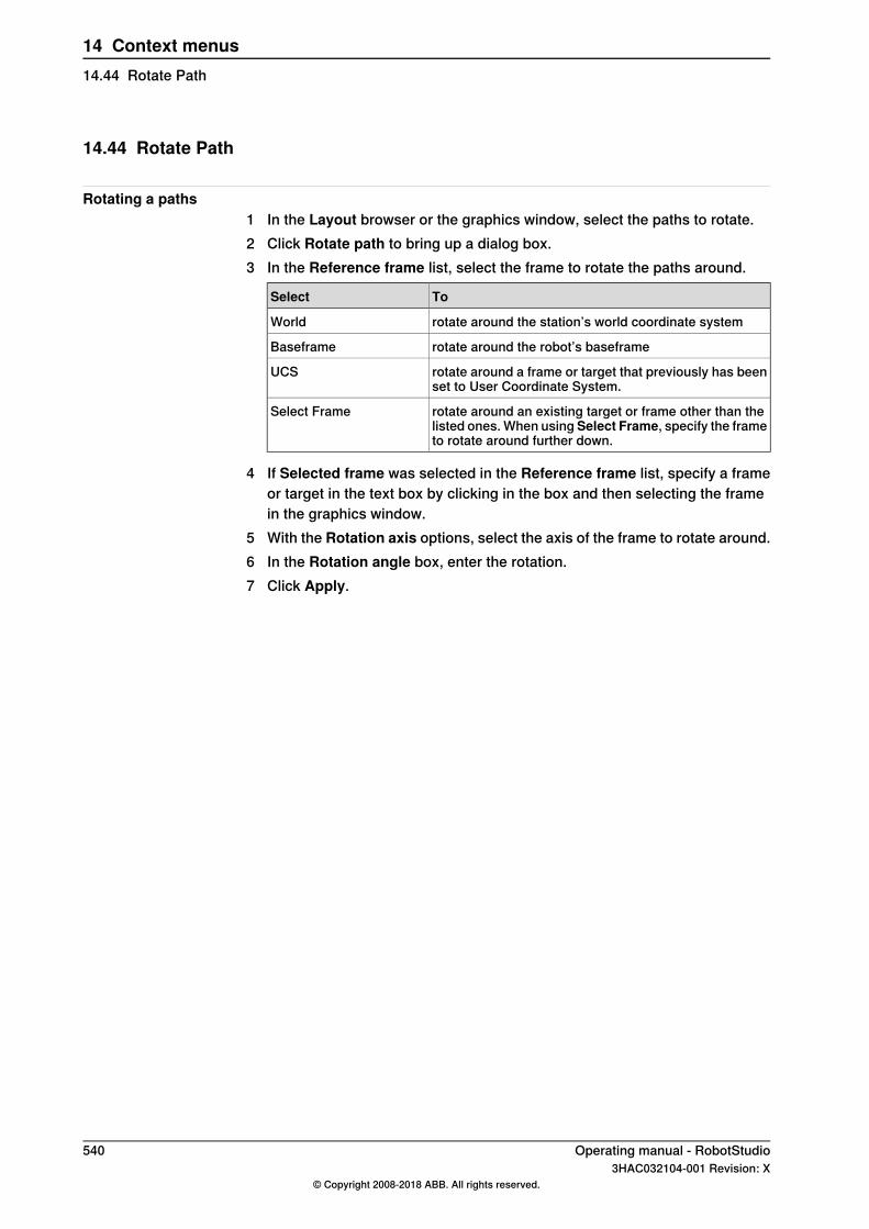
14.44 Rotate Path
Rotating a paths1 In the Layout browser or the graphics window, select the paths to rotate.2 Click Rotate path to bring up a dialog box.3 In the Reference frame list, select the frame to rotate the paths around.
ToSelect
rotate around the station’s world coordinate systemWorld
rotate around the robot’s baseframeBaseframe
rotate around a frame or target that previously has beenset to User Coordinate System.
UCS
rotate around an existing target or frame other than thelisted ones. When using Select Frame, specify the frameto rotate around further down.
Select Frame
4 If Selected frame was selected in the Reference frame list, specify a frameor target in the text box by clicking in the box and then selecting the framein the graphics window.
5 With the Rotation axis options, select the axis of the frame to rotate around.6 In the Rotation angle box, enter the rotation.7 Click Apply.
540 Operating manual - RobotStudio3HAC032104-001 Revision: X
© Copyright 2008-2018 ABB. All rights reserved.
14 Context menus14.44 Rotate Path

14.45 Set Local Origin
Setting the origin of the local coordinate system1 If the object you want to modify is a library component, first disconnect it
from the library.2 In the Layout browser or the graphics window, select the part to modify.3 Click Set Local Origin to bring up a dialog box.4 In the Set Local Origin dialog box, select the reference coordinate system
you want to use:
SelectIf you want to move
Localrelative to the part’s current local coordin-ate system
Parentrelative to the coordinate system of itsparent
Worldabsolute in the coordinate system of thestation
UCSrelative to a user-defined coordinate sys-tem
5 In the Position X, Y, Z boxes, either type the new position or, click to selectit in one of the value boxes and then click the point in the Graphics window.
6 Type the Orientation.7 Click Apply.
Operating manual - RobotStudio 5413HAC032104-001 Revision: X
© Copyright 2008-2018 ABB. All rights reserved.
14 Context menus14.45 Set Local Origin

14.46 Set Normal to Surface
Setting the target orientation normal to a surface1 In the Paths & Targets browser, select the target to modify.2 Click Set Normal To Surface to bring up a dialog box.3 On the Selection Level toolbar, set the selection level.
• To align the target to a specific surface, set the selection level tosurface.
• To align the target to a specific point at the surface, set the selectionlevel to part.
4 In the graphics window, click the reference surface. This will transfer thename of the part or surface to the Surface box.
5 In the Approach Direction, click the button for the axis to be used as theapproach direction.
6 To set the distance between the surface and the target in the approachdirection, specify an Offset value.
7 Click Apply.
542 Operating manual - RobotStudio3HAC032104-001 Revision: X
© Copyright 2008-2018 ABB. All rights reserved.
14 Context menus14.46 Set Normal to Surface
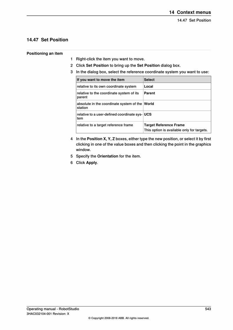
14.47 Set Position
Positioning an item1 Right-click the item you want to move.2 Click Set Position to bring up the Set Position dialog box.3 In the dialog box, select the reference coordinate system you want to use:
SelectIf you want to move the item
Localrelative to its own coordinate system
Parentrelative to the coordinate system of itsparent
Worldabsolute in the coordinate system of thestation
UCSrelative to a user-defined coordinate sys-tem
Target Reference Framerelative to a target reference frameThis option is available only for targets.
4 In the Position X, Y, Z boxes, either type the new position, or select it by firstclicking in one of the value boxes and then clicking the point in the graphicswindow.
5 Specify the Orientation for the item.6 Click Apply.
Operating manual - RobotStudio 5433HAC032104-001 Revision: X
© Copyright 2008-2018 ABB. All rights reserved.
14 Context menus14.47 Set Position

14.48 Tool Compensation
Offsetting a path to compensate for tool radius1 In the Paths&Targets browser or the graphics window, select the path.2 Click Tool Compensation to bring up a dialog box.3 In the Distance box, enter the size of the compensation (normally, the tool
radius).4 Using the Direction options, select whether the new path shall be on the
left or the right side of the current path.5 Click Apply.
Note
Tool Compensation function supports only planar paths. In planar paths,the targets are in the same plane. User will be notified when a selectedpath is non-planar.
544 Operating manual - RobotStudio3HAC032104-001 Revision: X
© Copyright 2008-2018 ABB. All rights reserved.
14 Context menus14.48 Tool Compensation
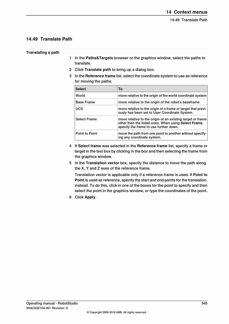
14.49 Translate Path
Translating a path1 In the Paths&Targets browser or the graphics window, select the paths to
translate.2 Click Translate path to bring up a dialog box.3 In theReference frame list, select the coordinate system to use as reference
for moving the paths.
ToSelect
move relative to the origin of the world coordinate systemWorld
move relative to the origin of the robot’s baseframeBase Frame
move relative to the origin of a frame or target that previ-ously has been set to User Coordinate System.
UCS
move relative to the origin of an existing target or frameother then the listed ones. When using Select Frame,specify the frame to use further down.
Select Frame
move the path from one point to another without specify-ing any coordinate system.
Point to Point
4 If Select frame was selected in the Reference frame list, specify a frame ortarget in the text box by clicking in the box and then selecting the frame fromthe graphics window.
5 In the Translation vector box, specify the distance to move the path alongthe X, Y and Z axes of the reference frame.Translation vector is applicable only if a reference frame is used. If Point toPoint is used as reference, specify the start and end points for the translation,instead. To do this, click in one of the boxes for the point to specify and thenselect the point in the graphics window, or type the coordinates of the point.
6 Click Apply.
Operating manual - RobotStudio 5453HAC032104-001 Revision: X
© Copyright 2008-2018 ABB. All rights reserved.
14 Context menus14.49 Translate Path
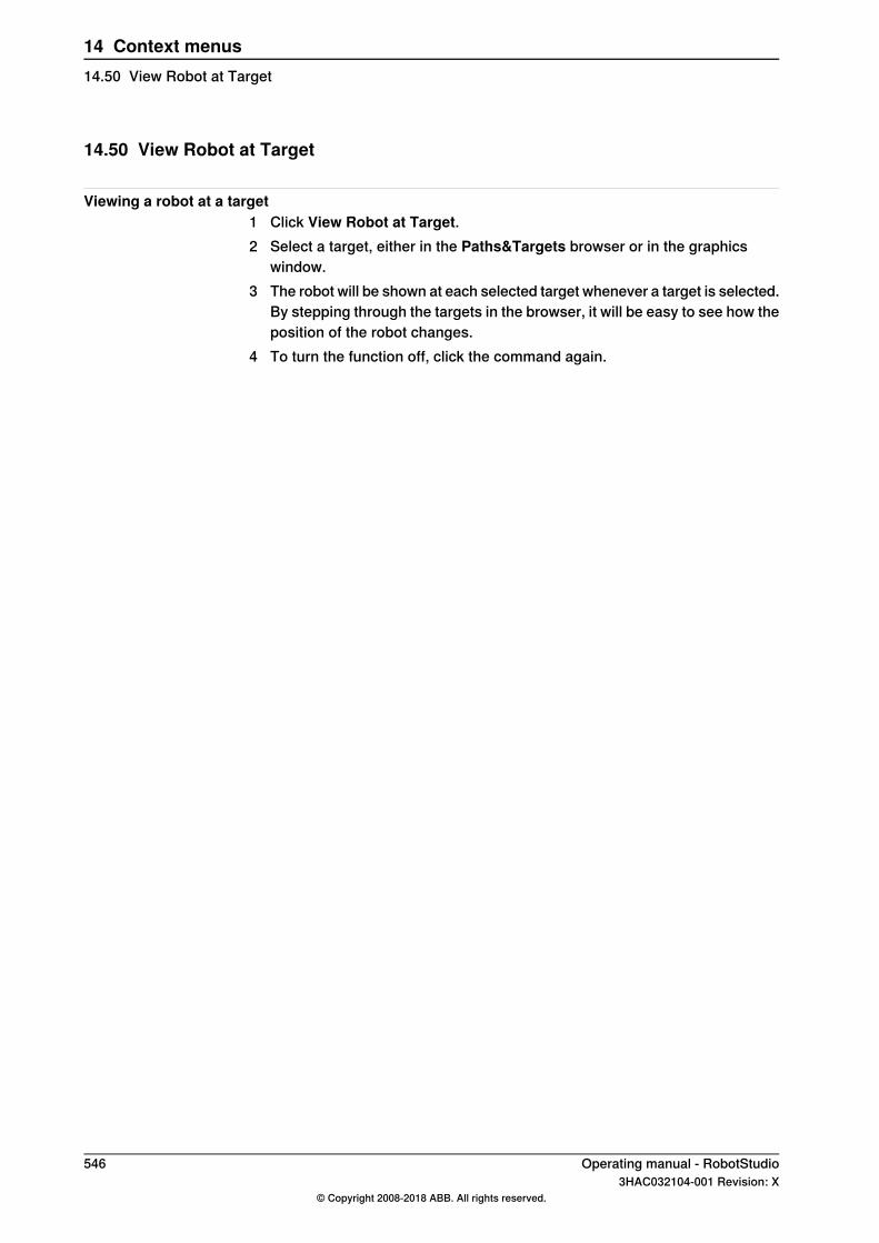
14.50 View Robot at Target
Viewing a robot at a target1 Click View Robot at Target.2 Select a target, either in the Paths&Targets browser or in the graphics
window.3 The robot will be shown at each selected target whenever a target is selected.
By stepping through the targets in the browser, it will be easy to see how theposition of the robot changes.
4 To turn the function off, click the command again.
546 Operating manual - RobotStudio3HAC032104-001 Revision: X
© Copyright 2008-2018 ABB. All rights reserved.
14 Context menus14.50 View Robot at Target
14.51 View Tool at Target
Viewing a tool at a target1 Click View Tool at Target and select the tool you want to view at the target.2 Select a target, either in the Paths&Targets browser or in the graphics
window. You can also multiselect targets to show several copies of the tool.A copy of the tool will be shown at the selected target. By stepping throughthe targets in the browser, it is easy to see how the tool orientation changes.
3 To turn the function off, click the command and clear the check box.
Operating manual - RobotStudio 5473HAC032104-001 Revision: X
© Copyright 2008-2018 ABB. All rights reserved.
14 Context menus14.51 View Tool at Target

This page is intentionally left blank

15 ScreenMaker tab15.1 Introduction to ScreenMaker
What is ScreenMaker?ScreenMaker is a tool in RobotStudio for developing custom screens. It is used tocreate customized FlexPendant GUIs without learning Visual Studio developmentenvironment and .NET programming.
Why use ScreenMaker?A customized operator interface on the factory floor is the key to a simple roboticsystem. A well-designed custom operator interface presents the right amount ofinformation at the right time and in the right format to the user.
GUI concepts
xx0800000226
A GUI makes it easier for people to work with industrial robots by presenting avisual front end to the internal workings of a robotic system. For FlexPendant GUIapplications, the graphical interface consists of a number of screens, eachoccupying the user window area (the blue box in the figure above) of theFlexPendant touch screen. A FlexPendant screen is then composed of a numberof smaller graphical components in a design layout. Typical controls (sometimesreferred as widgets or graphic components) include buttons, menus, images, andtext fields.
Continues on next pageOperating manual - RobotStudio 5493HAC032104-001 Revision: X
© Copyright 2008-2018 ABB. All rights reserved.
15 ScreenMaker tab15.1 Introduction to ScreenMaker
A user interacts with a GUI application by:• Clicking a button• Selecting from a menu• Typing a text in a text box• Scrolling
An action such as clicking a button is called an event. Whenever an action isperformed, an event is sent to the GUI application. The exact content of an eventis solely dependent on the graphic component itself. Different components triggerdifferent types of events. The GUI application responds to the events in the ordergenerated by the user. This is called event-driven programming, since the mainflow of a GUI application is dictated by events rather than being sequential fromstart to finish. Due to the unpredictability of the user’s actions, one major task indeveloping a robust GUI application is to ensure that it works correctly no matterwhat the user does. Of course, a GUI application can, and actually does, ignoreevents that are irrelevant.The event handler holds sets of actions to be executed after an event occurs.Similar to trap routines in the RAPID program, the event handler allows theimplementation of application-specific logic, such as running a RAPID program,opening a gripper, processing logic or calculating.In summary, from a developer’s point of view, a GUI consists of at least two parts:
• the view part: layout and configuration of controls• the process part: event handlers that respond to events
Modern GUI development environments often provide a form designer, a (WhatYou See Is What You Get ) WYSIWYG tool to allow the user to select, position andconfigure the widgets. As for event handlers, typically the developer must use aspecial programming language recommended by the development environment.
Note
ScreenMaker does not support Undo/Redo operations.
Continues on next page550 Operating manual - RobotStudio
3HAC032104-001 Revision: X© Copyright 2008-2018 ABB. All rights reserved.
15 ScreenMaker tab15.1 Introduction to ScreenMakerContinued
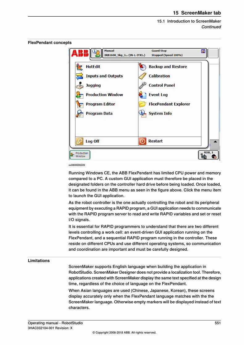
FlexPendant concepts
xx0800000228
Running Windows CE, the ABB FlexPendant has limited CPU power and memorycompared to a PC. A custom GUI application must therefore be placed in thedesignated folders on the controller hard drive before being loaded. Once loaded,it can be found in the ABB menu as seen in the figure above. Click the menu itemto launch the GUI application.As the robot controller is the one actually controlling the robot and its peripheralequipment by executing a RAPID program, a GUI application needs to communicatewith the RAPID program server to read and write RAPID variables and set or resetI/O signals.It is essential for RAPID programmers to understand that there are two differentlevels controlling a work cell: an event-driven GUI application running on theFlexPendant, and a sequential RAPID program running in the controller. Thesereside on different CPUs and use different operating systems, so communicationand coordination are important and must be carefully designed.
LimitationsScreenMaker supports English language when building the application inRobotStudio. ScreenMaker Designer does not provide a localization tool. Therefore,applications created with ScreenMaker display the same text specified at the designtime, regardless of the choice of language on the FlexPendant.When Asian languages are used (Chinese, Japanese, Korean), these screensdisplay accurately only when the FlexPendant language matches with the theScreenMaker language. Otherwise empty markers will be displayed instead of textcharacters.
Operating manual - RobotStudio 5513HAC032104-001 Revision: X
© Copyright 2008-2018 ABB. All rights reserved.
15 ScreenMaker tab15.1 Introduction to ScreenMaker
Continued

15.2 Development environment
OverviewThis section presents an overview of the ScreenMaker development environmentfor creating user screens.
en0900000584
DescriptionParts
Displays group of icons organized in a logical sequenceof functions. See Ribbon on page 553.
Ribbon1
Shows the active screen project and lists the screens thatare defined in the project. For more information, seeManaging projects on page 557.
Project explorer2
Layout to design the screen with the available controls.Design area3
Displays information about the events that occur duringScreenMaker development.
Output window4
Displays a list of available controls. For more information.see ToolBox on page 554.
ToolBox / Properties5
Contains the available properties and events of the selec-ted control(s). The value of the properties can either be afixed value or a link to an IRC5 data or an ApplicationVariable. For more information, see Properties window onpage 556.
Continues on next page552 Operating manual - RobotStudio
3HAC032104-001 Revision: X© Copyright 2008-2018 ABB. All rights reserved.
15 ScreenMaker tab15.2 Development environment
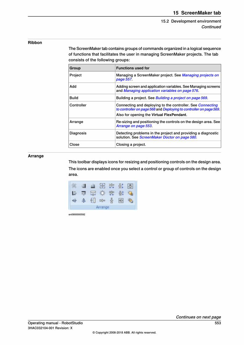
RibbonThe ScreenMaker tab contains groups of commands organized in a logical sequenceof functions that facilitates the user in managing ScreenMaker projects. The tabconsists of the following groups:
Functions used forGroup
Managing a ScreenMaker project. See Managing projects onpage 557.
Project
Adding screen and application variables. See Managing screensand Managing application variables on page 576.
Add
Building a project. See Building a project on page 569.Build
Connecting and deploying to the controller. See Connectingto controller on page568 andDeploying to controller on page569.
Controller
Also for opening the Virtual FlexPendant.
Re-sizing and positioning the controls on the design area. SeeArrange on page 553.
Arrange
Detecting problems in the project and providing a diagnosticsolution. See ScreenMaker Doctor on page 580.
Diagnosis
Closing a project.Close
ArrangeThis toolbar displays icons for resizing and positioning controls on the design area.The icons are enabled once you select a control or group of controls on the designarea.
en0900000592
Continues on next pageOperating manual - RobotStudio 5533HAC032104-001 Revision: X
© Copyright 2008-2018 ABB. All rights reserved.
15 ScreenMaker tab15.2 Development environment
Continued
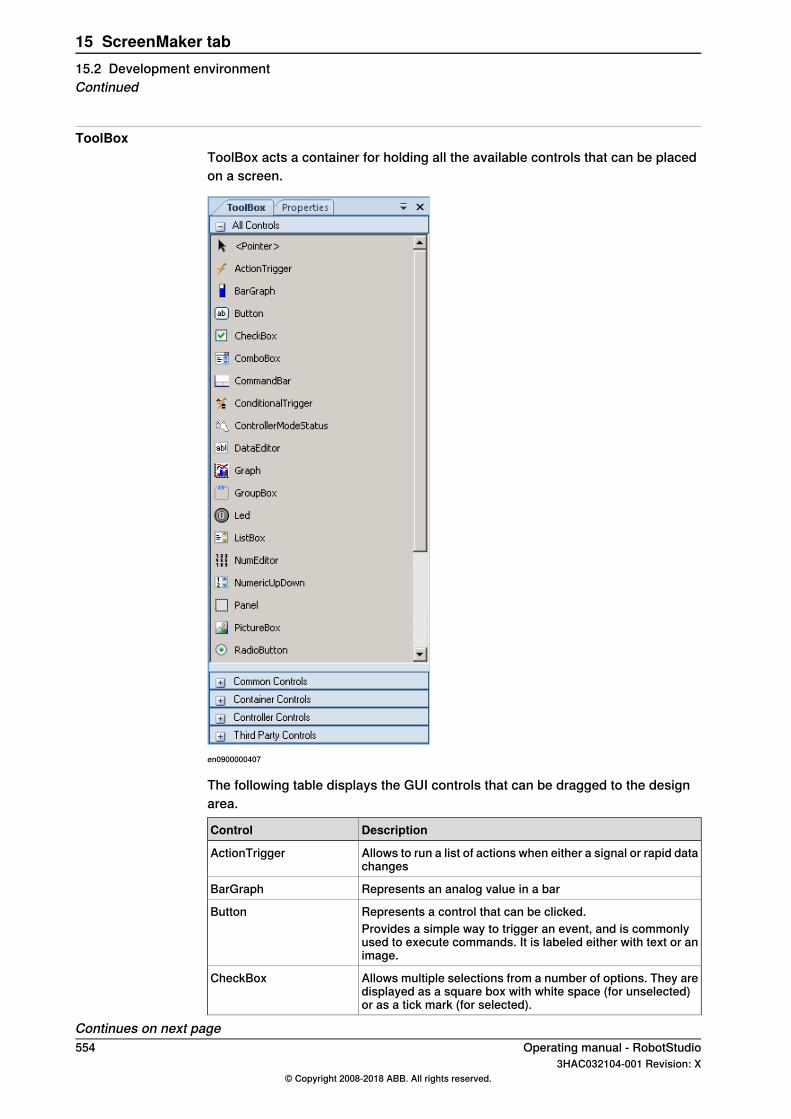
ToolBoxToolBox acts a container for holding all the available controls that can be placedon a screen.
en0900000407
The following table displays the GUI controls that can be dragged to the designarea.
DescriptionControl
Allows to run a list of actions when either a signal or rapid datachanges
ActionTrigger
Represents an analog value in a barBarGraph
Represents a control that can be clicked.ButtonProvides a simple way to trigger an event, and is commonlyused to execute commands. It is labeled either with text or animage.
Allows multiple selections from a number of options. They aredisplayed as a square box with white space (for unselected)or as a tick mark (for selected).
CheckBox
Continues on next page554 Operating manual - RobotStudio
3HAC032104-001 Revision: X© Copyright 2008-2018 ABB. All rights reserved.
15 ScreenMaker tab15.2 Development environmentContinued

DescriptionControl
Represents a control that enables to select items from a listComboBoxCombination of a drop-down list and a textbox. It allows youto either type a value directly into the control or choose fromthe list of existing options.It is not possible to add I/O signals to the combobox/listboxcontrol.
Provides a menu system for a ScreenFormCommandBar
Allows to define conditions while defining action triggers. Anaction is triggered, if there is any change in value of the databound.
ConditionalTrigger
Displays the mode of the Controller (Auto - Manual)ControllerModeStatus
Represents a text box control that can be used to edit the data.DataEditor
Represents a control that plots data with lines or bars.Graph
Represents a Windows control that displays a frame around agroup of controls with an optional caption.
GroupBox
Is a container used to group a set of graphic components. Itusually has a title at the top.
Displays a two states value, like a Digital Signal.LED
Represents a control to display a list of items.ListBoxAllows the user to select one or more items from a list con-tained within a static, multiple line text box.
Represents a text box control that can be used to edit a number.When the user clicks it, a Numpad is opened.
NumEditor
It is not recommended to add a NumEditor in a container con-trol.
Represents a spin box that displays numeric values.NumericUpDown
Used to group collection of controls.Panel
Represents a picture box control that displays images.PictureBox
Allows to select only one of a predefined set of options.RadioButton
Displays the execution status of the Controller Rapid Domain(Running - Auto)
RapidExecutionStatus
Represents a Windows button control that calls a RapidRoutinewhen clicked
RunRoutineButton
Displays and lets change a two states value, like a DigitalOutput Signal.
Switch
Manages a set of tab pages.TabControl
Very commonly used widget that displays text, a label is usuallystatic, that is, it has nointeractivity. A label generally identifiesa nearby text box or other graphic component.
TpsLabel
Used to change the values of RAPID variables or Applicationvariables.
VariantButton
Note
For more information on using these controls and their properties, see the sectionDevelopment environment on page 552 and the chapterUsing the FlexPendantSDK of the Application manual - FlexPendant SDK.
Continues on next pageOperating manual - RobotStudio 5553HAC032104-001 Revision: X
© Copyright 2008-2018 ABB. All rights reserved.
15 ScreenMaker tab15.2 Development environment
Continued

Properties windowA control is characterized by its properties and events. Properties describe theappearance and behavior of the component, while events describe the ways inwhich a control notifies its internal state change to others. By changing the valueof a property, the controls have a different look and feel, or exhibit different behavior.
en0900000408
DescriptionElement
Displays the selected component, and lists theavailable components of the active designscreen.
Graphical component name panel1
en0900000409
Properties window toolbar2
1 Organizes table panel in categories2 Organizes table panel alphabetically3 Displays Properties in table panel4 Displays Events in table panel
Displays all the properties or events in two-columns. The first column shows the propertyor event name, the second shows the value ofthe property or name of the event handler.
Table panel3
Display information about a property or event.Information panel4
556 Operating manual - RobotStudio3HAC032104-001 Revision: X
© Copyright 2008-2018 ABB. All rights reserved.
15 ScreenMaker tab15.2 Development environmentContinued

15.3 Working with ScreenMaker
15.3.1 Managing projects
OverviewThis section describes how to manage projects in ScreenMaker. A complete cycleincludes creating, saving, building, connecting, and deploying a ScreenMakerproject.You can manage a project (create, delete, load, or save) either from theScreenMaker ribbon or the context menu.
Creating a new projectScreenMaker does not support Unicode characters. Hence, do not use thesecharacters when you create a ScreenMaker project.Use the following procedure to create a new project:
1 Click New from the ScreenMaker ribbon or right-click Project context menuand select New Project.The New ScreenMaker Project dialog box appears.
Note
You can create a new project either from ScreenMaker installed templatesor ScreenMaker custom templates.
2 To create a new project from the ScreenMaker installed templates,a Click Simple Project.b Enter a name and specify the location for the new project. By default,
the new project is saved on C:\My Documents\RobotStudio\MyScreenMaker Projects.
c Click OK.d A screen MainScreen(main) is added in the tree view.
3 To create a new project from the ScreenMaker custom templates,a Click Basic, Standard, or Extended.b Enter a name and specify the location for the new project. By default,
the new project is saved on C:\My Documents\RobotStudio\MyScreenMaker Projects.
c Click OK.
Note
• If you select the templateBasic, a project with two screens are created.• If you select the template Standard, a project with four screens are
created.• If you select the template Extended, a project with six screens are
created.
Continues on next pageOperating manual - RobotStudio 5573HAC032104-001 Revision: X
© Copyright 2008-2018 ABB. All rights reserved.
15 ScreenMaker tab15.3.1 Managing projects
Loading a project or templateUse this procedure to load an existing project or an existing template:
1 Click Open from the ScreenMaker ribbon or right-click Project context menuand select Open Project.The Open Screen Project File dialog box appears.
WARNING
A warning message appears when you open an existing ScreenMakerproject where the FlexPendant SDK version is different from the versionthe project was created.
2 Browse to the location of the project file or template file to be loaded andclick Open.
Note
You can also load an existing project using a quick access method.1 Click Recent from the ScreenMaker ribbon or right-click Project context
menu and select Recent Projects.2 Select the project file from the list of most recently opened projects.
Saving a projectTo save a project or template, follow this step:
• Click Save from the ScreenMaker ribbon or right-click Project context menuand select Save.
To save the existing project or template with a new name, follow this step:• Click SaveAs from the ScreenMaker ribbon or right-click Project context
menu and select SaveAs.
Note
• Project files are saved with the extension *.smk.• Template files are saved with the extension *.smt.
SaveAs FlexPendant ProjectTo save the ScreenMaker project as a FlexPendant project, in the project contextmenu, click SaveAs FlexPendant Project.The project is saved with the extension *.csproj which can be opened usingMicrosoft Visual Studio 2008.
Continues on next page558 Operating manual - RobotStudio
3HAC032104-001 Revision: X© Copyright 2008-2018 ABB. All rights reserved.
15 ScreenMaker tab15.3.1 Managing projectsContinued

Designing screensThis section describes adding, copying, renaming, deleting, and editing a screen.
OverviewThe Form designer is a tool to edit or design a screen. It allows you to design thescreen with the required controls and the design area resembles a FlexPendantscreen.
Editing a screenTo edit a screen, follow these steps:
1 Drag a control from the toolbox and drop it on the design area.The Properties window displays all the properties of the control.
2 Select the control and resize or reposition for configuration.
Note
You can either select a single control or multiple controls:• Single control : Left-click the control on the design area or select the
control from the list in the Properties window.• Multiple controls: Left-click on the design area, drag the mouse and
create a window selecting all the controls.
3 Click the smart tag on the upper right corner of the control to perform thebasic tasks of configuration. See Configuring data binding on page 577.
Note
You can perform additional configuration by editing the attributes in theProperties window. See Properties window on page 556.
Using ScreenMaker controlsThis section describes building the GUIs using the following controls from theToolBox.
ActionTriggerAn action trigger initiates an event, such as making a hidden object visible whenan action is performed using a control. It allows to run a list of actions when theproperty value changes. The property value can be bound to a signal, rapid data,or application variable.ActionTrigger control can also be used to invoke the application from RAPID.Use this procedure to add an ActionTrigger control::
Action
Drag an ActionTrigger control from the ToolBox on to the design area.1
Continues on next pageOperating manual - RobotStudio 5593HAC032104-001 Revision: X
© Copyright 2008-2018 ABB. All rights reserved.
15 ScreenMaker tab15.3.1 Managing projects
Continued
Action
You can modify the name, set the default value and configure data binding valuefor a ActionTrigger control.
• To set the values of a property, see Properties window on page 556.• You can set the trigger event for an ActionTrigger to any of the event handler
created either from a control or from an Events Manager option.• To configure the data binding values, see Configuring data binding on
page 577.• To set the application variables, see Managing application variables on
page 576.
2
Note
An action is not triggered when the screen is launched for the first time, but istriggered when there is a difference in the bound value at any point of time. Thisfunctionality is supported only in RobotWare 5.12.02 or higher.
Example: Consider a signal being bound to the value property. The value of thesignal changes at runtime on performing a specific action. The event handlerconfigured for ActionTrigger control gets triggered based on this signal valuechange.
TpsLabelTpsLabel is a standard Windows label that displays a descriptive text.Use this procedure to add a TpsLabel control:
ActionStep
Drag a TpsLabel control from the ToolBox on to the design area.1
You can set the values, setup events, configure data binding values and set theapplication values for a TpsLabel control.
• To set the values of a property, see Properties window on page 556.• To set up the events, see Defining Events on page 564.• To configure the data binding values, see Configuring data binding on
page 577.• To set the application variables, see Managing application variables on
page 576.
2
You can set the option Allow Multiple States to true and change the property.1 Click Allow Multiple States. The StatesEditor dialog box appears.2 Click the check-box Allow Multi-States, select the properties to change from
Properties For States and click OK.
3
The controls Button, PictureBox, and TpsLabel support AllowMultipleStates. Formore information on how to use AllowMultipleStates, see Picture object andchanging images due to I/O on page 583.
PanelPanel is used to group a collection of controls.Use this procedure to add a Panel control:
ActionStep
Drag a Panel control from the ToolBox on to the design area.1
You can add a group of controls to a panel.2
Continues on next page560 Operating manual - RobotStudio
3HAC032104-001 Revision: X© Copyright 2008-2018 ABB. All rights reserved.
15 ScreenMaker tab15.3.1 Managing projectsContinued
ActionStep
You can modify the name, set the default value and binding value for a Panel control.• To set the values of a property, see Properties window on page 556.• To set up the events, see Defining Events on page 564 .• To configure the data binding values, see Configuring data binding on
page 577.• To set the application variables, see Managing application variables on
page 576.
3
Note
Currently only EventHandler, CancelEventHandlers, and MouseEventArgs aresupported.
ControllerModeStatusControllerModeStatus displays the mode of the controller (Auto - Manual).Use this procedure to add a ControllerModeStatus control:
ActionStep
Drag a ControllerModeStatuscontrol from the ToolBox on to the design area.1
You can set the values, setup events, configure data binding values, and set theapplication variables for a ControllerModeStatus control.
• To set the values of a property, see Properties window on page 556.• To set up the events, see Defining Events on page 564.• To configure the data binding values, see Configuring data binding on
page 577.• To set the application variables, see Managing application variables on
page 576.
2
You can select the image to be displayed when the controller is in Auto mode andin Manual mode.
• Click AutoImage in the Properties window and browse to select the imageto be displayed in Auto mode.
• Click ManualImage in the Properties window and browse to select the imageto be displayed in Manual mode.
3
RapidExecutionStatusRapidExecutionStatus displays the execution status of the Controller Rapid Domain(Running - Auto). This control is usedUse this procedure to add a RapidExecutionStatus control:
ActionStep
Drag a RapidExecutionStatus control from the ToolBox on to the design area.1
You can set the values, setup events, configure data binding values, and set theapplication values for a RapidExecutionStatus control.
• To set the values of a property, see Properties window on page 556.• To set up the events, see Setup Events.• To configure the data binding values, see Configuring data binding on
page 577.• To set the application variables, see Managing application variables on
page 576.
2
Continues on next pageOperating manual - RobotStudio 5613HAC032104-001 Revision: X
© Copyright 2008-2018 ABB. All rights reserved.
15 ScreenMaker tab15.3.1 Managing projects
Continued
ActionStep
You can select the image to be displayed when the Program is running and isstopped.
• Click RunningImage in the Properties window and browse to select the imageto be displayed when the Program is running.
• Click StoppedImage in the Properties window and browse to select the imageto be displayed when the Program is stopped.
3
RunRoutineButtonRunRoutineButton represents a Windows button that calls a RapidRoutine whenclicked.
Note
To call a routine containing movements, you are not recommended to use theRunRoutine Button control. Instead use a normal button control to call a Traproutine. In the Trap routine, use instructions such as StopMove, StorePath,RestorePath and StartMove to control the movements of the robot.
Use this procedure to add a RunRoutineButton control:
ActionStep
Drag a RunRoutineButton control from the ToolBox on to the design area.1
Click the smart tag on the RunRoutineButton and select one of the following Run-RoutineButtonTasks.
• Define Actions before calling Routine• Select Routine to call• Define Actions after calling Routine
2
Click Define Actions before calling Routine to define an action/event before callingthe routine.
3
The Events Panel dialog box appears.
Click Define Actions after calling Routine to define an action/event afterre callingthe routine.
4
The Events Panel dialog box appears.
Click Select Routine to call.5The Controller Object Binding dialog box appears.
In the Properties window, set the value for the following properties:• RoutineToCall - Set the routine to be called. Indicates the RAPID Routine
that will be called when this button is pressed.• AllowInAuto - Set to True or False. Indicates if the routine could be called
in the Auto mode.• TextAlign - Set to MiddleLeft and MiddleCenter. Indicates the text alignment.
Note the following restrictions:• You cannot bind RunRoutineButton to built-in Service routines.• Only user defined procedures with no arguments can be bound.• Set the PP to task before performing action through RunRoutineButton.
6
Continues on next page562 Operating manual - RobotStudio
3HAC032104-001 Revision: X© Copyright 2008-2018 ABB. All rights reserved.
15 ScreenMaker tab15.3.1 Managing projectsContinued
CommandBarCommandBar allows you to add menu items in a controlled and organized order.Use this procedure to add menu items to the CommandBar control:
ActionStep
Drag a CommandBar control from the ToolBox on to the design area.1The CommandBar appear at the bottom of the screen.
Click the smart tag on the CommandBar and select Add/Remove Items.2The MenuItem Collection Editor window appears.
Click Add.3A new menu item is added and its properties are displayed which can be edited.Note that while editing the menu item, ensure that the property Text is filled. If not,nothing appears on the CommandBar.
To remove the menu item, select the menu item and Click Remove.4
Click Close to close the MenuItem Collection Editor window.5
To add an event to a menu item, for example menuItem1 on the command bar,use this procedure:
ActionStep
Go to the Properties window and select menuItem1 from the drop-down list.1
Click Events icon and then double-click the Click event. This opens the EventsPanel dialog for the Click event.
2
Click Add Action from the Events Panel dialog. This opens a sub-list of actions.3
Click an action from the sub-list of actions to add it to menuItem1's Click event.4
Note
ScreenMaker does not support the FlexPendant controls feature to add sub menuitems on CommandBar.
VariantButtonThe VariantButton control is a simple button control with additional features andproperties. Using this control, you can change the values of RAPID or Applicationvariables.Use this procedure to add the VariantButton control:
ActionStep
Drag a VariantButton control from the ToolBox on to the design area.1
You can perform the following VariantButton tasks from the SmartTag:• Define Actions before value change• Define Actions after value change
2
Continues on next pageOperating manual - RobotStudio 5633HAC032104-001 Revision: X
© Copyright 2008-2018 ABB. All rights reserved.
15 ScreenMaker tab15.3.1 Managing projects
Continued

ActionStep
You can set the following VariantButton specific properties from the Propertieswindow:
• Select Increment or Decrement from Behavior drop down. The default beha-vior of VariantButton is Increment.
• Select StepRate and set the rate at which the value must be varied.• Select DataType to which the value should be bound and set the value
property of the selected datatype.Supports only the RAPID datatypes,Num and Dnum. For more information on databinding, see Configuring data binding on page 577.
3
You can also perform the following common tasks from the Properties windows:• Set BackColor, ForeColor, Location, and Size of the control.• Select True or False from the Visible dropdown to hide or unhide the control.• Select True or False from the Enabled drop down to enable or disable the
control.
4
ConditionalTriggerThe ConditionalTrigger button defines the condition while defining action triggers.An action will be triggered if there is a change in the value of the data bound.Use this prcodedure to add the ConditionalTrigger control:
ActionStep
Drag a ConditionalTrigger control from the ToolBox on to the design area.1
You can set the following ConditionalTrigger properties from the Properties window:• Select the condition to execute from the Condition drop down. The following
are the supported conditions AND, OR, XOR, NOT, and EQUAL.• Select True or False from the Enabled drop down to enable or disable the
control.• Select LHS and RHS and bind the data value to Controller Object or Applic-
ation Variable. For more information on data binding, see Data binding onpage 577.
2
Defining EventsEvent handler is a set of actions to be executed after an event occurs.To set up an event, follow these steps:
1 Select the control for which the event handler is to be defined.2 Open the Events Panel dialog box in any one of the following ways:
• Double-click the control.• Right-click the control, select Events Manager, click Add enter the
name, and click OK and close.• Click smart tag and select the task from the list.• In the Properties window, click Events icon and select the desired
event from the list.3 Click Add Action to add an action from a predefined list of actions.
The following table lists the set of predefined actions:• Open Screen• Close Screen
Screens
Continues on next page564 Operating manual - RobotStudio
3HAC032104-001 Revision: X© Copyright 2008-2018 ABB. All rights reserved.
15 ScreenMaker tab15.3.1 Managing projectsContinued
• Set a Digital Signal• Invert a Digital Signal• Pulse a Digital Signal• Read a Signal• Write a Signal• Reset a Digital Signal
Signals
• Read a Rapid Data• Write a Rapid Data
RapidData
• Read and WriteApplication Variable• Call another Action list• Call .NET method• Call Custom Action• Call FP Standard View
Advanced
4 Select the action from the left window and perform the following:• Click Delete to delete the action.• Click Move Up or Move Down to change the order of execution of
actions.5 Click OK
Deleting an event handlerTo delete a user created event handler, do the following:
1 Right-click the control, select Events Manager. The Events Manager dialogbox appears.
2 Select the event handler to be deleted from the list and click Delete.
Advanced Actions
Call another Action ListExisting event handlers from Events Manager can be reused by other controlswhile defining actions for event. You can call another event handler from an existingevent handler.In the following example, listbox1_SelectedIndexChanged event handler is calledfrom comboBox1_SelectionIndexChanged event handler.Select the Show warning message before performing actions check box to havea warning displayed before you can perform these actions.
Call .NET MethodYou can import the dlls and add references to the Advanced tab of the ProjectProperties dialog box.Once the references are defined, .NET methods appear in the Project Propertiesdialog box and can be included in the Actions list which will be executed onperforming the desired action.The .NET assembly supports only public static methods.Double click the method and bind the return value to the application variable.
Continues on next pageOperating manual - RobotStudio 5653HAC032104-001 Revision: X
© Copyright 2008-2018 ABB. All rights reserved.
15 ScreenMaker tab15.3.1 Managing projects
Continued

Binding can be done only to the application variable. For more information, seeApplication variable data binding on page 578.
Note
ScreenMaker allows you to call static methods of the public classes defined inanother DLL. This DLL is usually a class library or a control library. It has thefollowing limitations and the user should be aware of them while using .Net DLLs.
• DLL’s references must be in the same directory in order to load the DLL.• ScreenMaker provides access only to the static methods which contain basic
data types such as string, int, double, boolean, object.
The following procedure provides information on creating a .NET assembly. Thisassembly can be added as a reference to ScreenMaker Project and for performingcertain computations which are not directly possible using ScreenMaker or to callmethods of FlexPendant or PCSDK.Use Visual Studio 2010 or above to create a .NET assembly.
1 Create a new project with Class Library as your template.2 Create public static methods like the following.
namespace SMDotNetMethods
{
public class Methods
{
/// <summary>
/// Inverts a boolean value
/// </summary>
/// <param name ="Value">input boolean value</param>
/// <returns>inverted boolean value</returns>
public static bool InvertBool(bool value)
{
return (value == false);
}
/// <summary>
/// Increments a numerical value
/// </summary>
/// <param name="value">value to be incremented</param>
/// <returns>incremented value</returns>
public static double Increment(double value)
{
return (value + 1);
}
}
}
3 Build the project.4 Use the assembly generated from this Class Library project.5 Add it as a reference to the ScreenMaker project.
Continues on next page566 Operating manual - RobotStudio
3HAC032104-001 Revision: X© Copyright 2008-2018 ABB. All rights reserved.
15 ScreenMaker tab15.3.1 Managing projectsContinued
Call Custom ActionYou can add an user control to the ScreenMaker toolbox and call a custom methodfor that control by defining it in the ScreenMaker.dll.config file.Call Custom Action supports only the Graph control.
Call FP Standard ViewStandard FlexPendant screens can be opened on any action performed on thecontrol. The standard FlexPendant screens include Rapid Editor, Rapid Data,LogOff, Jogging, Backup and Restore.For example, on button1_click, Rapid Editor view is opened.
Editing the property valueYou can edit the property value of a control from the Properties window in threeways:
1 By typing the numerics, strings and text. For example, Location, Size, Nameetc.
2 By selecting the predefined values from the list. For example, BackColor,Font etc.
3 By entering the values in the dialog box. For example, Enabled, States,BaseValue etc.
Deleting an event handlerTo delete a user created event handler, do the following:
1 Right-click the control, select Events Manager. The Events Manager dialogbox appears.
2 Select the event handler to be deleted from the list and click Delete.
Modifying Project propertiesProject properties define the properties of the ScreenMaker project, including howthe GUI is loaded and displayed in the FlexPendant.Use this procedure to modify the project properties:
1 Right-click Project context menu and select Properties.The Project Properties dialog box appears.
2 In the Display tab under Caption, enter the text in the Caption of theApplication field to edit the caption.The updated caption appears in the ABB Menu on the right side.
3 In the Display tab under ABB Menu, select the following options,
DescriptionOption
application is visible to the left in the ABB Menu.Left
application is visible to the right in the ABB Menu.Right
application is not visible at all in the ABB Menu.None
Continues on next pageOperating manual - RobotStudio 5673HAC032104-001 Revision: X
© Copyright 2008-2018 ABB. All rights reserved.
15 ScreenMaker tab15.3.1 Managing projects
Continued
Note
The applications that uses the option None cannot be run on RobotWarereleases earlier than 5.11.01.
4 In theDisplay tab underABBMenu, browse and select theABBmenu image.5 In the Display tab under TaskBar, browse and select the TaskBar image.
Note
By default, the Use Default Image and Use Menu Image checkbox isenabled and the deafult image tpu-Operator32.gif is selected.
6 In the Display tab under Startup , select Automatic to load the screenautomatically at the Startup.
Note
By default, the start up type is Manual.
7 In theAdvanced tab underRun Settings, select Launch virtual FlexPendantafter deploying checkbox.The virtual FlexPendant will be launched after deploying the ScreenMakerproject to the virtual controller.
Note
This feature is not applicable if connected to a real controller.
8 In the Project Properties dialog, select the General tab to view the projectproperties which includes, Name, Assembly, Version and Path.Version displays the specific versions of Controller and FlexPendant SDKthat the ScreenMaker project uses.
Connecting to controllerUse this procedure to connect to both real and virtual controllers:
1 Click Connect from the ScreenMaker ribbon or right-click Project contextmenu and select Connect.The Select a Robot Controller dialog box appears.
Note
Click the Connect dropdown from the ScreenMaker ribbon to directlyconnect to the controller.
Continues on next page568 Operating manual - RobotStudio
3HAC032104-001 Revision: X© Copyright 2008-2018 ABB. All rights reserved.
15 ScreenMaker tab15.3.1 Managing projectsContinued
2 Click Refresh to find a list of all the available controllers.
Note
By default, the currently connected controller is highlighted and has a smallicon before the row as an indicator.
3 Select the controller to be connected from the list and click Connect.The connection status is displayed in the Project tree view.
To remove the connection with the controller, click Disconnect from the Projectcontext menu.
Building a projectThe result from building the ScreenMaker project is a set of files including DLL fileand images. The ScreenMaker project can be compiled into binary format (.dll)that can be deployed on a FlexPendant.Use this procedure to build a project:
1 Click Build from the ScreenMaker ribbon or right-click Project context menuand select BuildThe result is displayed in the output window.
Deploying to controllerUse this procedure to deploy a ScreenMaker project to a real controller or virtualcontroller:
1 Connect to the controller you want to deploy to. SeeConnecting to controlleron page 568.
2 ClickDeploy from the ScreenMaker ribbon or right-click Project context menuand select Deploy Screen to Controller.The Download dialog box appears displaying the progress of download. Itdisappears once the download is successful.The TpsViewxxxxxx.dll file is downloaded.
3 Restart the controller.
Note
• If a real controller is used, you can reboot the FlexPendant by movingits joystick three times to the right, once to the left, and once towardsyou.
• If a virtual controller is used, you can reboot the FlexPendant by closingthe virtual FlexPendant window.
Closing a projectTo close a project, follow this step:
• Right-click Project context menu and select Close Project.
Continues on next pageOperating manual - RobotStudio 5693HAC032104-001 Revision: X
© Copyright 2008-2018 ABB. All rights reserved.
15 ScreenMaker tab15.3.1 Managing projects
Continued
Closing ScreenMakerTo close ScreenMaker, follow this step:
• Click Close ScreenMaker from the ScreenMaker ribbon.
Managing ScreenMaker Widgets
What is a widgetA widget is a visual building block, containing an information arrangement, whichrepresents an aspect of a robot application. It is a reusable and sharable userinterface building block which can help speed up the development of screens.A ScreenMaker widget is similar in function to the widgets used in computerprogramming. The widget is an element of a graphical user interface (GUI) thatdisplays an information arrangement which is changeable by the user. The widgets,when combined in an application, hold data processed by the application and theavailable interactions on this data.
Widget WorkflowWidget created from ScreenMaker can be used in ScreenMaker application andin Production Screen application.The following are the steps required to create a Widget in ScreenMaker.
1 Start RobotStudio.2 Launch ScreenMaker.3 Create a new Widget Project or open an existing widget project.
For information on how to create a new widget project, see Creating aScreenMaker widget project on page 571.
4 Connect to a real or a virtual controller, as required.5 If required, change the widget properties, using theWidget Properties dialog
box.For information on the Widget Properties dialog box, see Specifying widgetproperties on page 574.
6 Drag-and-drop the necessary user interface components, as you would in anormal ScreenMaker project.
7 Link the user interface properties to the IRC5 data or to the applicationvariables
8 Build the widget project. The widget component is created and saved in...\Documents\RobotStudio\Widget Components folder.
Sample use caseConsider a case where you want to design a production screen which can do thefollowing:
• Display a graph• Show alarms• Show status of the controller
Continues on next page570 Operating manual - RobotStudio
3HAC032104-001 Revision: X© Copyright 2008-2018 ABB. All rights reserved.
15 ScreenMaker tab15.3.1 Managing projectsContinued
To achieve this:1 Create a new widget project in ScreenMaker and names it as, for example,
GraphWidget.2 Drags-and-drop the graph control and other necessary controls on the widget
form.3 Connect to a real or virtual controller, as required.4 Bind the controls to the controller data.5 Use the widget properties dialog box, to change the size of the widget.6 Build the project7 Download the output to the production screen.
You can then repeat the above steps to create widgets either in the same or indifferent projects based on your need to show the alarms and the status of thecontroller.
Creating a ScreenMaker widget project1 On the ScreenMaker tab, clickNew. Alternatively, in the project context menu,
click New Project.The New ScreenMaker Project dialog box appears.
2 Under Widget Templates, click Widget.3 Specify a name for the widget project.
ScreenMaker widgets projects are by default stored in the...\Documents\RobotStudio\Widget Projects folder.
4 Click Ok.The widget project along with a screen MainScreen(main), appears in the treeview. The widget project has .wzp file name extension. Widgets also appear in theToolbox.
Note
• You can open one widget project at any time. Close an open widget projectbefore opening a new one.
• A widget project has only one screen, the main screen, on which the widgetsare designed. All controls defined on a widget are considered as one widget.
• Widgets are loaded into the toolbox from a folder that contains the widgetcomponent DLLs, from Additional Options folder under MediaPool and fromRobotApps Repository. If you delete the widget components from theselocations (...\Documents\RobotStudio\Widget Components), thenthe widgets will not appear in the Toolbox.
Creating Production Screen WidgetScreenMaker helps the user to create two types of widgets, Production Screenwidget and Standard widget. Controls in a widget can be bound to rapid or signaldata.
Continues on next pageOperating manual - RobotStudio 5713HAC032104-001 Revision: X
© Copyright 2008-2018 ABB. All rights reserved.
15 ScreenMaker tab15.3.1 Managing projects
Continued

The Production Screen option is a framework for creating a customized GUI thatcan be used to present process data and status and execute FlexPendantapplications.To run widgets on the Production Screen, FlexPendant Interface option must beselected. For more information on Production Screen. Use the following procedureto create the Production Screen widget.
1 In the Screenmaker ribbon, select New. The New Project dialog opens2 Select Widget Template to create a new widget project.3 Drag and drop controls to the widget.4 Select Widget Properties, Widget Properties dialog opens.5 Under Type, click Production Screen and click OK.
Continues on next page572 Operating manual - RobotStudio
3HAC032104-001 Revision: X© Copyright 2008-2018 ABB. All rights reserved.
15 ScreenMaker tab15.3.1 Managing projectsContinued

6 Build the project.
xx1400000275
The ProductionSetup.xml file must be updated with widget details to view thewidget that was created in the Production Screen. You can findProductionSetup.xmlunder $System\HOME\ProdScr and Widget components under$System\HOME\ProdScr\tps.An example of widget detail is provided here:
<Widget>
<Name>Widget_9</Name>
<Page>1</Page>
<Assembly>Widget_9.dll</Assembly>
<Type>Widget_9.Widget_9</Type>
Continues on next pageOperating manual - RobotStudio 5733HAC032104-001 Revision: X
© Copyright 2008-2018 ABB. All rights reserved.
15 ScreenMaker tab15.3.1 Managing projects
Continued
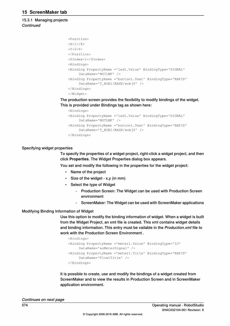
<Position>
<X>1</X>
<Y>2<Y>
</Position>
<ZIndex>1</ZIndex>
<Bindings>
<Binding PropertyName ="led1.Value" BindingType="SIGNAL"DataName="MOTLMP" />
<Binding PropertyName ="button1.Text" BindingType="RAPID"DataName="T_ROB1/BASE/wobj0" />
</Bindings>
</Widget>
The production screen provides the flexibility to modify bindings of the widget.This is provided under Bindings tag as shown here:
<Bindings>
<Binding PropertyName ="led1.Value" BindingType="SIGNAL"DataName="MOTLMP" />
<Binding PropertyName ="button1.Text" BindingType="RAPID"DataName="T_ROB1/BASE/wobj0" />
</Bindings>
Specifying widget propertiesTo specify the properties of a widget project, right-click a widget project, and thenclick Properties. The Widget Properties dialog box appears.You set and modify the following in the properties for the widget project:
• Name of the project• Size of the widget - x,y (in mm)• Select the type of Widget
- Production Screen: The Widget can be used with Production Screenenvironment
- ScreenMaker: The Widget can be used with ScreenMaker applications
Modifying Binding Information of WidgetUse this option to modify the binding information of widget. When a widget is builtfrom the Widget Project, an xml file is created. This xml contains widget detailsand binding information. This entry must be vailable in the Production.xml file towork with the Production Screen Environment .
<Bindings>
<Binding PropertyName ="meter1.Value" BindingType="IO"DataName="aoMeterSignal" />
<Binding PropertyName ="meter1.Title" BindingType="RAPID"DataName="Flow1Title" />
</Bindings>
It is possible to create, use and modify the bindings of a widget created fromScreenMaker and to view the results in Production Screen and in ScreenMakerapplication environment.
Continues on next page574 Operating manual - RobotStudio
3HAC032104-001 Revision: X© Copyright 2008-2018 ABB. All rights reserved.
15 ScreenMaker tab15.3.1 Managing projectsContinued

Building and DeployingThe output of the Widget Project is a single Widget Component dll file, for example,TpsViewMyWidget.dll. The widgets built from the Widget Project are used in theScreenMaker project. Widgets cannot be deployed to the controller fromScreenMaker. If Widgets are used in ScreenMaker projects, it gets deployed.When the ScreenMaker project which uses a widget is built, the widget componentis added as a reference to the project.When the ScreenMaker project output is deployed to the controller, the referencedwidget components are also copied to the system HOME folder.
Operating manual - RobotStudio 5753HAC032104-001 Revision: X
© Copyright 2008-2018 ABB. All rights reserved.
15 ScreenMaker tab15.3.1 Managing projects
Continued
15.3.2 Application variables
OverviewApplication Variables are variables defined inside a ScreenMaker application. Anapplication variable is similar to a RAPID variable. It supports the data typessupported by RAPID, such as num, dnum, string, tooldata, wobjdata, and so on.An application variable’s definition includes its name, data type and initial value.During the execution of the ScreenMaker application, an application variable hasa persistent value. It can store values coming from controller data or can be usedto write values to controller data. Therefore, it is like an intermediate persistentvariable which is used during RAPID execution along with other RAPID variables.
Managing application variablesTo create, delete, and rename an application variable, follow these steps:
1 On the ScreenMaker tab, in the Add group, click Application Variables.Alternatively, in the ScreenMaker browser, right-click the project, and thenclick Application Variables.The Project Application Variables dialog box appears.
2 Click Add and define the name, type and value of the new variable.3 Select the variable, click Delete to delete a variable.4 Select the variable, clickRename, enter the new name and clickOK to rename
a variable.5 Click Close.
You can view the application variables related to a project listed in the ProjectApplication Variables dialog box. To filter and view the variables according to theirdata types, use the Type list.
Note
For information on application variable data binding, seeData binding on page577.
576 Operating manual - RobotStudio3HAC032104-001 Revision: X
© Copyright 2008-2018 ABB. All rights reserved.
15 ScreenMaker tab15.3.2 Application variables
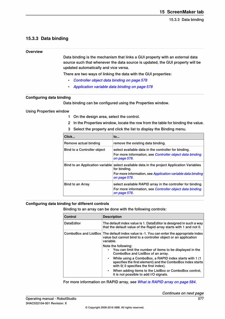
15.3.3 Data binding
OverviewData binding is the mechanism that links a GUI property with an external datasource such that whenever the data source is updated, the GUI property will beupdated automatically and vice versa.There are two ways of linking the data with the GUI properties:
• Controller object data binding on page 578• Application variable data binding on page 578
Configuring data bindingData binding can be configured using the Properties window.
Using Properties window1 On the design area, select the control.2 In the Properties window, locate the row from the table for binding the value.3 Select the property and click the list to display the Binding menu.
to...Click...
remove the existing data binding.Remove actual binding
select available data in the controller for binding.Bind to a Controller objectFor more information, see Controller object data bindingon page 578.
select available data in the project Application Variablesfor binding.
Bind to an Application variable
For more information, seeApplication variable data bindingon page 578.
select available RAPID array in the controller for binding.Bind to an ArrayFor more information, see Controller object data bindingon page 578.
Configuring data binding for different controlsBinding to an array can be done with the following controls:
DescriptionControl
The default index value is 1. DataEditor is designed in such a waythat the default value of the Rapid array starts with 1 and not 0.
DataEditor
The default index value is -1. You can enter the appropriate indexvalue but cannot bind to a controller object or an applicationvariable.
ComboBox and ListBox
Note the following:• You can limit the number of items to be displayed in the
ComboBox and ListBox of an array.• While using a ComboBox, a RAPID index starts with 1 (1
specifies the first element) and the ComboBox index startswith 0( 0 specifies the first index).
• When adding items to the ListBox or ComboBox control,it is not possible to add I/O signals.
For more information on RAPID array, see What is RAPID array on page 584.
Continues on next pageOperating manual - RobotStudio 5773HAC032104-001 Revision: X
© Copyright 2008-2018 ABB. All rights reserved.
15 ScreenMaker tab15.3.3 Data binding
Controller object data bindingController object data binding lets you to select the data in the controller for binding.Use the following procedure to set up a binding with controller objects.Open the Controller Object Binding dialog box and follow these steps:
1 In the Type of Object group, select either Rapid data or Signal data.2 In the Shared group, select Built-in data only to access shared Rapid data.
When you select Built-in data only, the option Signal data and the text boxModule are disabled.
3 If you have selected Rapid data, then in the Scope group, you can select atask and module from the list.When you select Signal data, the Scope group is disabled.
4 In the See list, select the desired data.
CAUTION
Unwanted toggle of I/O Signals & RAPID data when using data binding toEnabled propertiesWhen you bind the Enabled property to a Controller object, and a dialog (like theconfirm Going to Auto) is displayed on top, then your screen will be disabledand all the Enabled properties of all its controls will be set to false and all boundController objects with it.To avoid this behavior it is recommended to bind Enabled properties to I/O Signalswith Access Level: ReadOnly as this results in a one way binding.
Note
ScreenMaker supports binding to only constant and persistant variables. Thevariables must not be declared LOCAL. TASK PERS is supported.For example, the following binding is supported:PERS num n1:=0;
TASK PERS num n2:=0;
CONST num n3:=0;
The following binding is not supported:LOCAL PERS num n1:=0;
VAR num n1:=0
Note
A data bound RAPID array should be declared as PERS, it will not work asCONST.
Application variable data bindingUse the following procedure to set up a binding with project application variables.
Continues on next page578 Operating manual - RobotStudio
3HAC032104-001 Revision: X© Copyright 2008-2018 ABB. All rights reserved.
15 ScreenMaker tab15.3.3 Data bindingContinued

Open the Application Variables Bind Form dialog box and follow these steps:1 Select an application variable and the field to connect.2 Click Setup Variables to manage the variables.
The Project Application Variables dialog box appears. See Managingapplication variables on page 576.
3 Click OK.
Operating manual - RobotStudio 5793HAC032104-001 Revision: X
© Copyright 2008-2018 ABB. All rights reserved.
15 ScreenMaker tab15.3.3 Data binding
Continued

15.3.4 ScreenMaker Doctor
OverviewScreenMaker Doctor is a diagnostic solution to detect problems in the ScreenMakerproject. It helps analyze the project and fix errors such as:
• Unused events• Broken references, application variables, signals, modules, and Rapid data• RunRoutine issue
Using ScreenMaker DoctorUse this procedure to launch ScreenMaker Doctor, detect and report issues, andto view causes and solutions:
1 In the ScreenMaker ribbon, click ScreenMaker Doctor.The ScreenMaker Doctor Wizard opens.
2 Click Next.The wizard starts detecting issues and are reported as Completed Checks.The detected issues are categorized as:
• Broken References• Unused Events• Broken ApplicationVariables• Broken Signals• Broken Modules• Broken RapidData• RunRoutine issue• Broken Routine• Other Dependencies
3 Click View Causes and Solutions to generate a report.The left hand side of the report displays issues under each category and theright hand side of the report displays the Probable Causes and Solutions forthe issues.To check for issues again using the same instance, click Re-Detect Issues.
Note
In order to detect the signal data and RAPID, ScreenMaker project should beconnected to the controller.
Errors fixed by ScreenMaker DoctorThe following sections show you how errors, which can be fixed by ScreenMakerDoctor, may manifest.
Unused EventsThe following sequence of actions will result in creating unused events.
1 Create a ScreenMaker project.
Continues on next page580 Operating manual - RobotStudio
3HAC032104-001 Revision: X© Copyright 2008-2018 ABB. All rights reserved.
15 ScreenMaker tab15.3.4 ScreenMaker Doctor

2 Define events for the controls.3 Define the events Button1_Click and Button2_Click for the controls
Button1and Button2 respectively.4 Delete the control Button1. The event Button1_Clickwill still exist. An unused
event is created.You can run ScreenMaker Doctor to detect and fix this error.
Broken ReferenceThe following sequence of actions will result in creating broken references.
1 Create a ScreenMaker project.2 Define events for the controls.3 Define the events Button1_Click and Button2_Click for the controls
Button1and Button2 respectively.4 Define action ScreenOpen - Screen2 for the event Button1_Click.5 Delete or rename the screen. A broken reference is created.
You can run ScreenMaker Doctor to detect and fix this error.
Broken Application VariablesThe following sequence of actions will result in creating broken application variables.
1 Create a ScreenMaker project.2 Add an Application variable to the project.3 Rename or delete the Application variable. No error is reported.
An error is reported during the run time due to the broken application variable.You can run ScreenMaker Doctor to detect and fix this error.
Broken Rapid Data/SignalsIf rapid data is bound but not found in the controller connected in the ScreenMakerproject, then perform the following procedure:
1 Create a ScreenMaker project.2 Connect to a controller.3 Bind the properties of the controls with controller data.4 Build the project and deploy it to the controller.
The application works.5 Connect the ScreenMaker project to another controller and deploy the same
project.The application produces errors in the FlexPendant.
6 Run ScreenMaker Doctor. It detects that RapidData is not found in thecontroller, thereby suggesting to define the same.
Broken ModulesIf modules are bound but not found in the controller connected in the ScreenMakerproject, then perform the following procedure:
1 Create a ScreenMaker project.2 Connect to a controller.3 Bind the properties of the controls with controller data.
Continues on next pageOperating manual - RobotStudio 5813HAC032104-001 Revision: X
© Copyright 2008-2018 ABB. All rights reserved.
15 ScreenMaker tab15.3.4 ScreenMaker Doctor
Continued

4 Build the project and deploy to controller.The application works.
5 Connect the ScreenMaker project to another controller and deploy the same.The application produces errors in the FlexPendant.
6 Run ScreenMaker Doctor.It detects that the module in which the rapid data was defined is not foundin the controller, thereby suggesting to define the same. ScreenMaker doctoralso detects Hidden modules.
RunRoutine IssueA check is made whether ScreenMaker.sys file is loaded on the controller or not.An issue is detected if the system module is not loaded.You can run ScreenMaker Doctor to detect and fix this error.ASystem.NullReferenceException appears ifScreenMaker.sys entry is not availablein SYS.CFG file of robot system. To overcome this issue, add the following entryunderCAB_TASKS_MODULES in the SYS.CFG file and save and load the modifiedfile back into the robot system and then restart the robot system.File "RELEASE:/options/gtpusdk/ScreenMaker.sys" -ModName
"ScreenMaker"\ -AllTask -Hidden
582 Operating manual - RobotStudio3HAC032104-001 Revision: X
© Copyright 2008-2018 ABB. All rights reserved.
15 ScreenMaker tab15.3.4 ScreenMaker DoctorContinued

15.4 Frequently asked questions
How to deploy manually to a Virtual ControllerIf for any reason you wish to manually by-pass the Deploy button in RobotStudioand the virtual controller, the following information describes what files are to bemoved.
Actions
Location of output filesThe files that contain the FlexPendant application from ScreenMaker are found(for example) in the bin directory under the My ScreenMaker Projects located inthe My documents directory of the user.For example,MyDocuments\My ScreenMaker Projects\SCM_Example\binwhereSCM_Example is the example ScreenMaker project.The files in the bin directory are to be copied to a location where the VirtualFlexPendant can read them during the start of the FlexPendant.
Location where the Virtual FlexPendant reads the filesThe recommended location for manually copying the ScreenMaker output files isthe location of the virtual controller system.If the system is created manually from System Builder, it is located in the MyDocuments directory.For example, My Documents\IRB4400_60_SCM_Example\HOME whereIRB4400_60_SCM_Example is the example controller system.If the system is created by a Pack-and-Go and then restored, it is located in theRobotStudio\Systems folder.For example,MyDocuments\RobotStudio\Systems\IRB4400_60_SCM_Example\HOMEwhereIRB4400_60_SCM_Example is the example controller system.
Copy filesCopy the files from the ScreenMaker output to the Home directory of the virtualcontroller system.Restart the Virtual FlexPendant and the new application will be loaded.
Picture object and changing images due to I/OThe typical user objective is to have an image that changes when an I/O signalchanges, this is common for a digital input to affect the state on the FlexPendant.
ActionsThis is accomplished by adding an image and allowing the image to have multiplestates.Set AllowMultipleState to TRUE and set the Image state.Create two states and add images for each state:The Value property is extremely important. If binding to a digital input then thereare two states for the input, 0 and 1. Set the Value property to the value of the
Continues on next pageOperating manual - RobotStudio 5833HAC032104-001 Revision: X
© Copyright 2008-2018 ABB. All rights reserved.
15 ScreenMaker tab15.4 Frequently asked questions
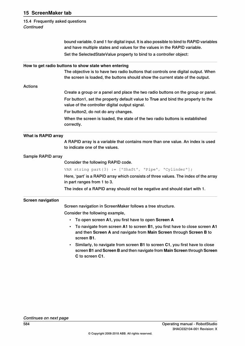
bound variable. 0 and 1 for digital input. It is also possible to bind to RAPID variablesand have multiple states and values for the values in the RAPID variable.Set the SelectedStateValue property to bind to a controller object:
How to get radio buttons to show state when enteringThe objective is to have two radio buttons that controls one digital output. Whenthe screen is loaded, the buttons should show the current state of the output.
ActionsCreate a group or a panel and place the two radio buttons on the group or panel.For button1, set the property default value to True and bind the property to thevalue of the controller digital output signal.For button2, do not do any changes.When the screen is loaded, the state of the two radio buttons is establishedcorrectly.
What is RAPID arrayA RAPID array is a variable that contains more than one value. An index is usedto indicate one of the values.
Sample RAPID arrayConsider the following RAPID code.VAR string part{3} := ["Shaft", "Pipe", "Cylinder"];
Here, ‘part’ is a RAPID array which consists of three values. The index of the arrayin part ranges from 1 to 3.The index of a RAPID array should not be negative and should start with 1.
Screen navigationScreen navigation in ScreenMaker follows a tree structure.Consider the following example,
• To open screen A1, you first have to open Screen A• To navigate from screen A1 to screen B1, you first have to close screen A1
and then Screen A and navigate from Main Screen through Screen B toscreen B1.
• Similarly, to navigate from screen B1 to screen C1, you first have to closescreenB1 andScreen B and then navigate fromMain Screen throughScreenC to screen C1.
Continues on next page584 Operating manual - RobotStudio
3HAC032104-001 Revision: X© Copyright 2008-2018 ABB. All rights reserved.
15 ScreenMaker tab15.4 Frequently asked questionsContinued

en0900000645
Operating manual - RobotStudio 5853HAC032104-001 Revision: X
© Copyright 2008-2018 ABB. All rights reserved.
15 ScreenMaker tab15.4 Frequently asked questions
Continued

15.5 Tutorial
15.5.1 Overview
About this chapterThis chapter is designed as a tutorial to take you through the steps involved indesigning a FlexArc Operator Panel.The FlexArc Operator Panel is a simple arc welding cell, where the robots canperform the following three different jobs.
DescriptionJob
Welding the partProduce
Service the welding gunService
Calibrate with bull’s eyeBull’s Eye
The FlexArc Operator Panel displays the following graphic elements:• Controller Status (controller mode auto or manual and the RAPID execution
status)• Part Status (number of produced parts, the average cycle time per part, and
a Reset button)• Robot jobs (Produce, Service, and Bull’s Eye) and Robot locations (Robot
at home position, service location, calibration location, and part location)• Start and Stop buttons
586 Operating manual - RobotStudio3HAC032104-001 Revision: X
© Copyright 2008-2018 ABB. All rights reserved.
15 ScreenMaker tab15.5.1 Overview
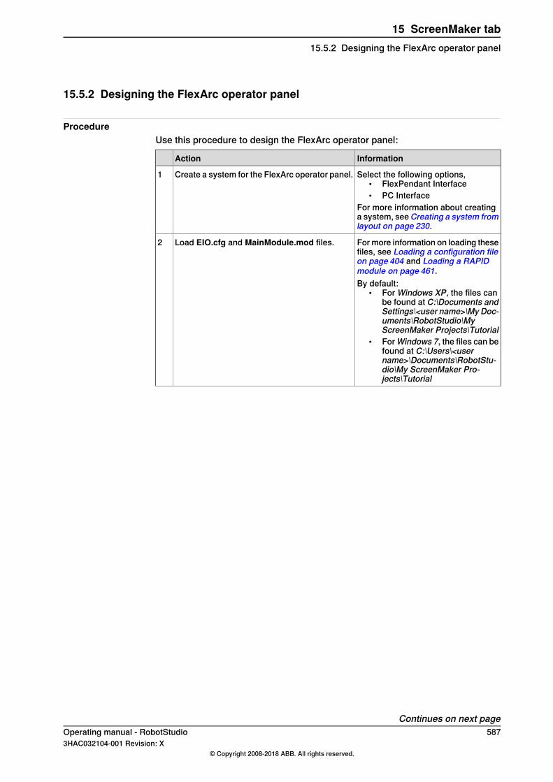
15.5.2 Designing the FlexArc operator panel
ProcedureUse this procedure to design the FlexArc operator panel:
InformationAction
Select the following options,• FlexPendant Interface• PC Interface
For more information about creatinga system, seeCreating a system fromlayout on page 230.
Create a system for the FlexArc operator panel.1
For more information on loading thesefiles, see Loading a configuration fileon page 404 and Loading a RAPIDmodule on page 461.
Load EIO.cfg and MainModule.mod files.2
By default:• For Windows XP, the files can
be found at C:\Documents andSettings\<user name>\My Doc-uments\RobotStudio\MyScreenMaker Projects\Tutorial
• ForWindows 7, the files can befound at C:\Users\<username>\Documents\RobotStu-dio\My ScreenMaker Pro-jects\Tutorial
Continues on next pageOperating manual - RobotStudio 5873HAC032104-001 Revision: X
© Copyright 2008-2018 ABB. All rights reserved.
15 ScreenMaker tab15.5.2 Designing the FlexArc operator panel

InformationAction
The following signals are created after loadingEIO.cfg file
Connec-tion
DescriptionTypeIO
Dl_Ro-botAtHome= DO_SIM-HOME
Indicates robotat home posi-tion
DlDl_Ro-botAtHome
Dl_RobotAt-Bullseye =DO_SIMBU-LLS
Indicates robotat bull's eyeposition
DlDl_RobotAt-Bullseye
Dl_RobotAt-Service =DO_SIM-SERVICE
Indicates robotat service posi-tion
DlDl_RobotAt-Service
Dl_PRO-DUCE =DO_PRO-DUCE
Indicates robotis producingpart
DlDl_PRO-DUCE
Simulate robotat home
DODO_SIM-HOME
Simulate robotat bull's eye
DODO_SIMBU-LLS
Simulate robotat service
DODO_SIM-SERVICE
Simulate robotis producingpart
DODO_PRO-DUCE
Gl_JOB =GO_JOB
The code ofordered job
GlGl_JOB
Simulate joborder
GOGO_JOB
3
For more information about creatinga station, see New tab on page 211.
Create an empty station in RobotStudio with thesystem created in the previous step.
4
For more information, see LaunchingScreenMaker on page 392.
Launch ScreenMaker from RobotStudio.5
For more informaton, see Creating anew project on page 557.
1 Enter the project name as Flex-ArcGUI, and save it in the de-fault location, C:\Users\<username>\Documents\RobotStu-dio\My ScreenMaker Pro-jects\Tutorial.
2 A new tabMainScreenis addedto the Design Surface.
Create a new ScreenMaker project.6
To customize how the GUI shouldappear on the FlexPendant, modifythe Project properties. For more in-formation, see Modifying Projectproperties on page 567.
Configure the Project properties.7
Continues on next page588 Operating manual - RobotStudio
3HAC032104-001 Revision: X© Copyright 2008-2018 ABB. All rights reserved.
15 ScreenMaker tab15.5.2 Designing the FlexArc operator panelContinued
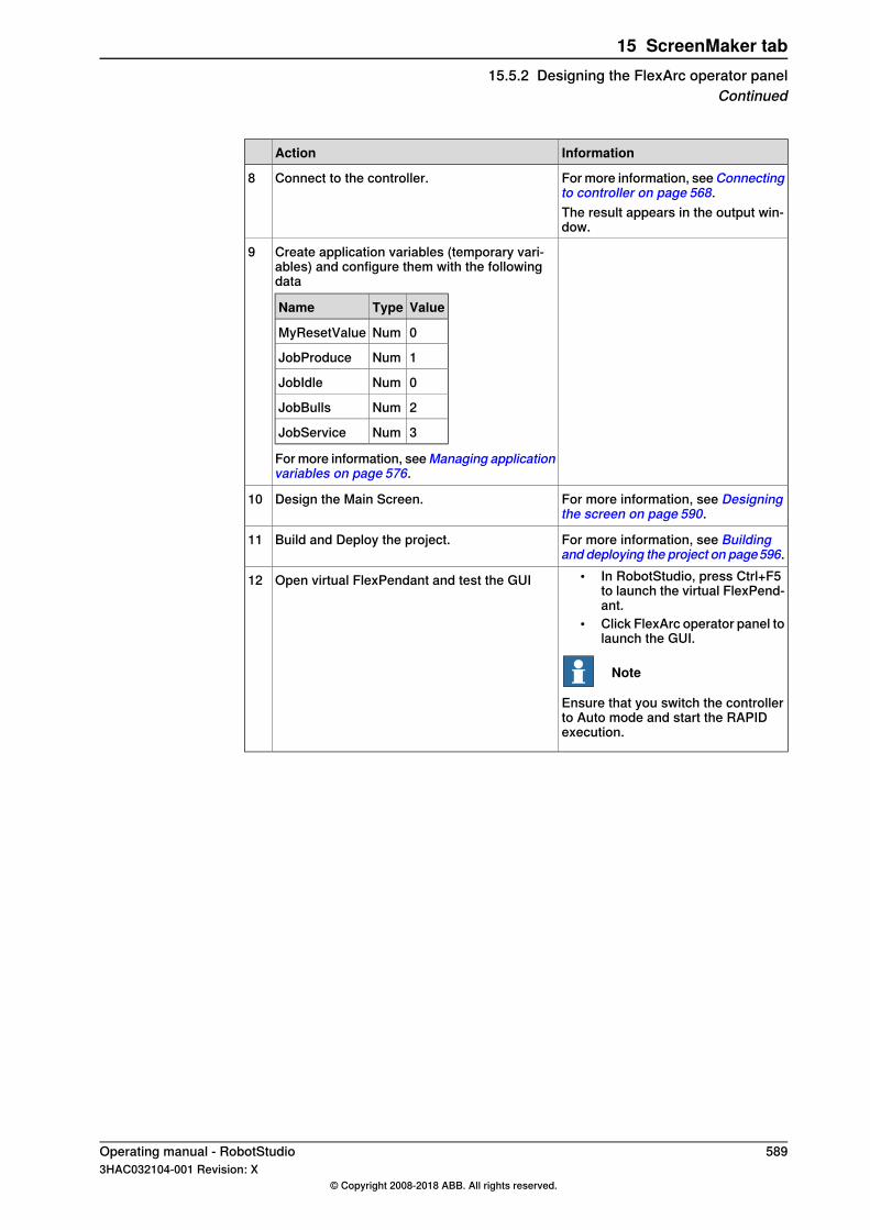
InformationAction
For more information, seeConnectingto controller on page 568.
Connect to the controller.8
The result appears in the output win-dow.
Create application variables (temporary vari-ables) and configure them with the followingdata
ValueTypeName
0NumMyResetValue
1NumJobProduce
0NumJobIdle
2NumJobBulls
3NumJobService
9
For more information, seeManaging applicationvariables on page 576.
For more information, see Designingthe screen on page 590.
Design the Main Screen.10
For more information, see Buildingand deploying the project on page596.
Build and Deploy the project.11
• In RobotStudio, press Ctrl+F5to launch the virtual FlexPend-ant.
• Click FlexArc operator panel tolaunch the GUI.
Note
Ensure that you switch the controllerto Auto mode and start the RAPIDexecution.
Open virtual FlexPendant and test the GUI12
Operating manual - RobotStudio 5893HAC032104-001 Revision: X
© Copyright 2008-2018 ABB. All rights reserved.
15 ScreenMaker tab15.5.2 Designing the FlexArc operator panel
Continued

15.5.3 Designing the screen
Introduction to designing the screenA major effort in the GUI project development is designing screens. The Formdesigner in the ScreenMaker allows you to drag controls from the toolbox to thedesign surface. Using the Properties window, you can resize, position, label, color,and configure the controls.
Designing FlexArc Operator Panel screenUse this procedure to design the FlexArc Operator Panel screen:
1 Drag a GroupBox control from the General category; place it on the designsurface and set the following values in the Properties window.
ValueProperty
14,45Location
150,100Size
Controller StatusTitle
LightGrayBackColor
2 Drag another GroupBox control from the General category; place it on thedesign surface and set the following values in the Properties window.
ValueProperty
14,170Location
150,204Size
Part StatusTitle
LightGrayBackColor
3 Drag a ControllerModeStatus control from the Controller Data category; placeit in the Controller Status groupbox created and set the following values inthe Properties window:
ValueProperty
19,40Location
44,44Size
LightGrayBackColor
4 Drag a RapidExecutionStatus control from the ControllerData category; placeit in the Controller Status groupbox created and set the following values inthe Properties window:
ValueProperty
80,40Location
44,44Size
LightGrayBackColor
Continues on next page590 Operating manual - RobotStudio
3HAC032104-001 Revision: X© Copyright 2008-2018 ABB. All rights reserved.
15 ScreenMaker tab15.5.3 Designing the screen
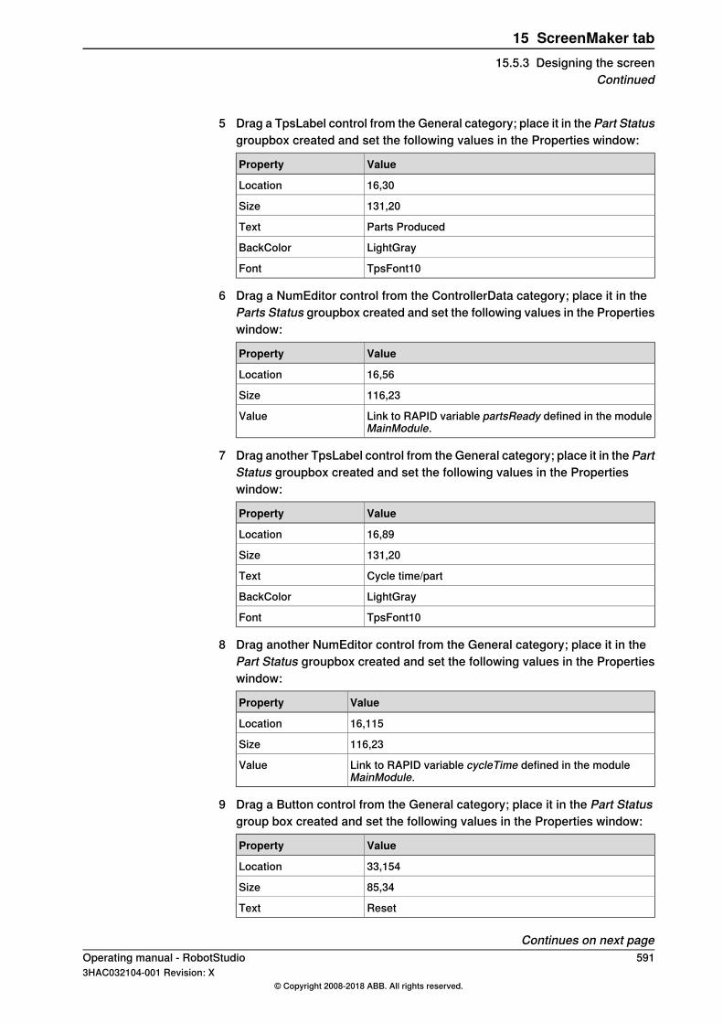
5 Drag a TpsLabel control from the General category; place it in the Part Statusgroupbox created and set the following values in the Properties window:
ValueProperty
16,30Location
131,20Size
Parts ProducedText
LightGrayBackColor
TpsFont10Font
6 Drag a NumEditor control from the ControllerData category; place it in theParts Status groupbox created and set the following values in the Propertieswindow:
ValueProperty
16,56Location
116,23Size
Link to RAPID variable partsReady defined in the moduleMainModule.
Value
7 Drag another TpsLabel control from the General category; place it in the PartStatus groupbox created and set the following values in the Propertieswindow:
ValueProperty
16,89Location
131,20Size
Cycle time/partText
LightGrayBackColor
TpsFont10Font
8 Drag another NumEditor control from the General category; place it in thePart Status groupbox created and set the following values in the Propertieswindow:
ValueProperty
16,115Location
116,23Size
Link to RAPID variable cycleTime defined in the moduleMainModule.
Value
9 Drag a Button control from the General category; place it in the Part Statusgroup box created and set the following values in the Properties window:
ValueProperty
33,154Location
85,34Size
ResetText
Continues on next pageOperating manual - RobotStudio 5913HAC032104-001 Revision: X
© Copyright 2008-2018 ABB. All rights reserved.
15 ScreenMaker tab15.5.3 Designing the screen
Continued
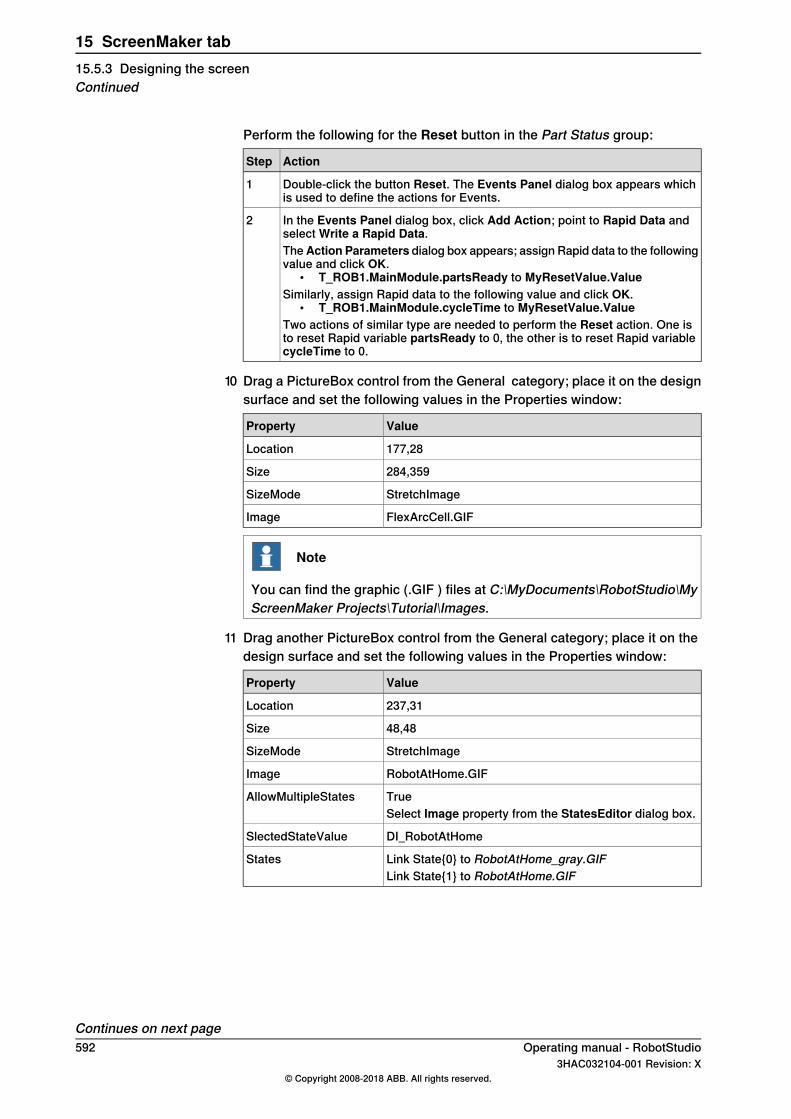
Perform the following for the Reset button in the Part Status group:
ActionStep
Double-click the button Reset. The Events Panel dialog box appears whichis used to define the actions for Events.
1
In the Events Panel dialog box, click Add Action; point to Rapid Data andselect Write a Rapid Data.
2
TheAction Parameters dialog box appears; assign Rapid data to the followingvalue and click OK.
• T_ROB1.MainModule.partsReady to MyResetValue.ValueSimilarly, assign Rapid data to the following value and click OK.
• T_ROB1.MainModule.cycleTime to MyResetValue.ValueTwo actions of similar type are needed to perform the Reset action. One isto reset Rapid variable partsReady to 0, the other is to reset Rapid variablecycleTime to 0.
10 Drag a PictureBox control from the General category; place it on the designsurface and set the following values in the Properties window:
ValueProperty
177,28Location
284,359Size
StretchImageSizeMode
FlexArcCell.GIFImage
Note
You can find the graphic (.GIF ) files at C:\MyDocuments\RobotStudio\MyScreenMaker Projects\Tutorial\Images.
11 Drag another PictureBox control from the General category; place it on thedesign surface and set the following values in the Properties window:
ValueProperty
237,31Location
48,48Size
StretchImageSizeMode
RobotAtHome.GIFImage
TrueAllowMultipleStatesSelect Image property from the StatesEditor dialog box.
DI_RobotAtHomeSlectedStateValue
Link State{0} to RobotAtHome_gray.GIFStatesLink State{1} to RobotAtHome.GIF
Continues on next page592 Operating manual - RobotStudio
3HAC032104-001 Revision: X© Copyright 2008-2018 ABB. All rights reserved.
15 ScreenMaker tab15.5.3 Designing the screenContinued
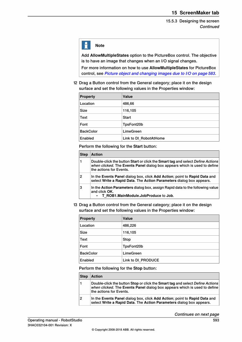
Note
Add AllowMultipleStates option to the PictureBox control. The objectiveis to have an image that changes when an I/O signal changes.For more information on how to use AllowMultipleStates for PictureBoxcontrol, see Picture object and changing images due to I/O on page 583.
12 Drag a Button control from the General category; place it on the designsurface and set the following values in the Properties window:
ValueProperty
486,66Location
116,105Size
StartText
TpsFont20bFont
LimeGreenBackColor
Link to DI_RobotAtHomeEnabled
Perform the following for the Start button:
ActionStep
Double-click the button Start or click the Smart tag and select Define Actionswhen clicked. The Events Panel dialog box appears which is used to definethe actions for Events.
1
In the Events Panel dialog box, click Add Action; point to Rapid Data andselect Write a Rapid Data. The Action Parameters dialog box appears.
2
In theAction Parameters dialog box, assign Rapid data to the following valueand click OK.
• T_ROB1.MainModule.JobProduce to Job.
3
13 Drag a Button control from the General category; place it on the designsurface and set the following values in the Properties window:
ValueProperty
486,226Location
116,105Size
StopText
TpsFont20bFont
LimeGreenBackColor
Link to DI_PRODUCEEnabled
Perform the following for the Stop button:
ActionStep
Double-click the button Stop or click the Smart tag and select Define Actionswhen clicked. The Events Panel dialog box appears which is used to definethe actions for Events.
1
In the Events Panel dialog box, click Add Action; point to Rapid Data andselect Write a Rapid Data. The Action Parameters dialog box appears.
2
Continues on next pageOperating manual - RobotStudio 5933HAC032104-001 Revision: X
© Copyright 2008-2018 ABB. All rights reserved.
15 ScreenMaker tab15.5.3 Designing the screen
Continued
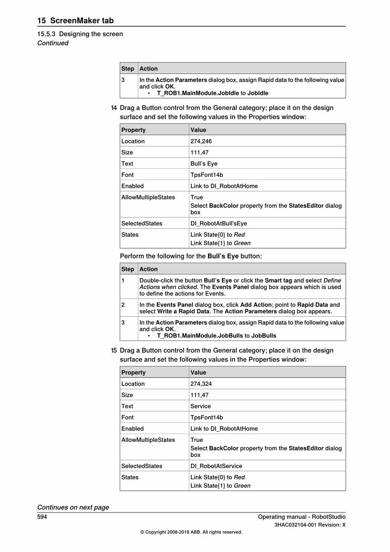
ActionStep
In theAction Parameters dialog box, assign Rapid data to the following valueand click OK.
• T_ROB1.MainModule.JobIdle to JobIdle
3
14 Drag a Button control from the General category; place it on the designsurface and set the following values in the Properties window:
ValueProperty
274,246Location
111,47Size
Bull’s EyeText
TpsFont14bFont
Link to DI_RobotAtHomeEnabled
TrueAllowMultipleStatesSelect BackColor property from the StatesEditor dialogbox
DI_RobotAtBull'sEyeSelectedStates
Link State{0} to RedStatesLink State{1} to Green
Perform the following for the Bull’s Eye button:
ActionStep
Double-click the button Bull’s Eye or click the Smart tag and select DefineActions when clicked. The Events Panel dialog box appears which is usedto define the actions for Events.
1
In the Events Panel dialog box, click Add Action; point to Rapid Data andselect Write a Rapid Data. The Action Parameters dialog box appears.
2
In theAction Parameters dialog box, assign Rapid data to the following valueand click OK.
• T_ROB1.MainModule.JobBulls to JobBulls
3
15 Drag a Button control from the General category; place it on the designsurface and set the following values in the Properties window:
ValueProperty
274,324Location
111,47Size
ServiceText
TpsFont14bFont
Link to DI_RobotAtHomeEnabled
TrueAllowMultipleStatesSelect BackColor property from the StatesEditor dialogbox
DI_RobotAtServiceSelectedStates
Link State{0} to RedStatesLink State{1} to Green
Continues on next page594 Operating manual - RobotStudio
3HAC032104-001 Revision: X© Copyright 2008-2018 ABB. All rights reserved.
15 ScreenMaker tab15.5.3 Designing the screenContinued

Perform the following for the Service button:
ActionStep
Double-click the button Service or click the Smart tag and select Define Ac-tions when clicked. The Events Panel dialog box appears which is used todefine the actions for Events.
1
In the Events Panel dialog box, click Add Action; point to Rapid Data andselect Write a Rapid Data. The Action Parameters dialog box appears.
2
In theAction Parameters dialog box, assign Rapid data to the following valueand click OK.
• T_ROB1.MainModule.JobService to JobService
3
Operating manual - RobotStudio 5953HAC032104-001 Revision: X
© Copyright 2008-2018 ABB. All rights reserved.
15 ScreenMaker tab15.5.3 Designing the screen
Continued

15.5.4 Building and deploying the project
Procedure1 From the ScreenMaker ribbon, click Build.
For more information on building the project, see Building a project onpage 569.
2 From the ScreenMaker ribbon, click Deploy.For more information on deploying the project, see Deploying to controlleron page 569.
3 In RobotStudio, press Ctrl+F5 to launch the Virtual Flexpendant and clickFlexArc Operator Panel to open the GUI.
Note
Ensure that you start the RAPID execution and switch the controller intoAuto mode.
596 Operating manual - RobotStudio3HAC032104-001 Revision: X
© Copyright 2008-2018 ABB. All rights reserved.
15 ScreenMaker tab15.5.4 Building and deploying the project
A Technical supportOverview
Contacting ABBIf you have any questions or problems with your RobotStudio installation, pleasecontact your local ABB Robotics Service representative, seehttp://www.abb.com/contacts.
Have the following in mind1 Running the latest version of RobotStudio ensures that it works properly and
also includes improvements and new product functionality. ABB recommendsthat you update to the latest version of RobotStudio whenever a new versionis available and before contacting ABB for support.
2 Provide a brief description explaining how to reproduce your problem.3 Provide screenshots if applicable. (Use ALT + PRINT SCREEN to get an
image of the active window instead of the entire screen.)4 Generate a Full Scan with the RobotStudio Support Tool available next to
RobotStudio in the Start menu. (Click Start > Programs > ABB Industrial IT> Robotics IT > RobotStudio > RobotStudio Support Tool, then click onRun Full Scan and then click Save Report. Save this report and attach itwith your problem description.
5 Provide us the following user information:a nameb companyc contact informationd name of the operating system including the language detailse subscription ID of the purchased licensef Machine ID, see Help section of File tab
License supportFor license-related questions, please contact the team responsible for licensesupport directly at [email protected]
Operating manual - RobotStudio 5973HAC032104-001 Revision: X
© Copyright 2008-2018 ABB. All rights reserved.
A Technical support

This page is intentionally left blank
IndexAABB library, 228action instruction
about, 32Add Controller, 386add to path, 493Adjust Robtargets, 472align frame orientation, 494align target orientation, 495Application grants, 438Application Variables, 576
create,delete, rename application variables, 576attach to object, 496Authenticate, 418
Edit User Accounts, 418Login as a Different User, 418Log in as Default User, 418Log off, 418Log off all controllers, 418UAS Grant Viewer, 418
auto configuration, 497AutoPath, 250
BBackup, 396
create backup, 396Back up
restore backup, 398browser
Layout, 53Paths & Targets, 54
CCAD file
troubleshoot and optimize, 94clean disk, 196collision
detection, 147sets, 147
configurationrobot axis, 39
configuration editor, 402instance editor, 403
configuration file, 201configuration monitoring
about, 40Configure data binding, 577
Using Binding menu, 577confJ
about, 40ConfL
about, 40Connecting a controller, 568Controller grants, 436
Backup and save, 436Calibration, 437Delete log, 437Edit RAPID code, 436Execute program, 436Full access, 436I/O write access, 436Manage UAS settings, 436Modify configuration, 436Modify controller properties, 437
Modify current value, 436Program debug, 437Read access to controller disks, 437Safety Controller, 437Write access to controller disks, 437
controller menu, 201Controller Shutdown, 447controller status window, 61
access, 62controller name, 61controller state, 61logged on as, 62operating mode, 61program execution state, 61system name, 61
controller systemcreate, 162
controller world coordinate system, 35control panel, 446
enable device, 446manual full speed, 446motors on, 446operation mode, 446release device, 446reset emergency stop, 446
convert frame to workobject, 499coordinate systems, 33cycle tme
measure, 152
Ddata binding
Controller object data binding, 578Data Binding, 577
Application variable data binding, 578data declaration, 30deployment package, 181detach, 503detecting collision, 148device browser, 425
Eelement
select, 74erase SD-card, 196event
create, 150events, 389external axis
program, 136
FFile transfer, 419
Controller explorer, 420PC explorer, 420
FlexPendant Viewer, 421frame
converting to workobject, 108crerating by points, 108
Framecreate, 238create from three points, 239
frames, 33function, 30
Ggeometry
Operating manual - RobotStudio 5993HAC032104-001 Revision: X
© Copyright 2008-2018 ABB. All rights reserved.
Index
troubleshoot and optimize, 94Go Offline, 426Grants, about, 161Grants, give to groups, 434graphics window, 72Group, about, 160group, add, 433group, add user, 432group, remove, 434group, rename, 433Groups, give grants, 434
Hhandle events, 204
date and time, 205event category, 205event code, 205event description, 206event log list, 204event title, 205event type, 204manage events, 206retrieve controller events, 206sequential number, 205
II/O
set, 151I/O system, 390
I/O signals, 197input signals, 197output signals, 197simulated signals, 197virtual signals, 197
import, 92import geometry, 236import library, 229instruction, 30
about, 32item
select, 74
Jjog
mechanism, 109robot, 109several mechanisms, 109
jog reorient, 271jointtarget
creating, 110
Kkeyboard shortcuts, 76
General commands, 76
LLayout browser, 53LED, 555library
troubleshoot and optimize, 94Load Parameters, 404local coordinate system
set, 100local origin
set, 100
MManage ScreenMaker project
Close ScreenMaker, 570ScreenMaker Doctor, 16, 553, 580
Manage ScreenMaker Project, 557Close project, 569Create project, 557Load project, 558Save project, 558
Manage Screens, 559Managing ScreenMaker Projects
Build project, 569MediaPool, 29Mirror, 522Modify project properties, 567module, 30move instruction
about, 32Move instruction
teach, 260MoveJ
teach, 260MoveL
teach, 260MultiMove
programming workflow, 129
Nnear-miss detection, 149network security, 24network settings, 157
firewall settings, 157local network connection, 157remote network connection, 157service port connection, 157
Oobject
select, 74set local origin, 100troubleshoot and optimize, 94
Offline and Online browser, 55Online Monitor, 427operator window, 63
enabling operator window, 63show virtual operator window, 63
orientations, 116align target, 118copy and apply, 119target normal to surface, 117unordered, 116
output window, 60event types, 60
Ppart
set local origin, 100Password, change for user, 432path, 112
about, 32compensating, 113creating, 112creating from curve, 112reversing, 112rotating, 113setting axis configuration, 112translating, 113
600 Operating manual - RobotStudio3HAC032104-001 Revision: X
© Copyright 2008-2018 ABB. All rights reserved.
Index

Paths & Targets browser, 54Placing an item, 533
Frame, 533One Point, 533Three Points, 533Two Frames, 533Two Points, 533
positioner.program, 136procedure, 30process time
measure, 152program
copy, 141programming
overview, 107Program Pointer, 476Properties, 423
Device Browser, 425Renaming the controller, 423Save System Diagnostics, 425Set controller ID, 423Set date and time, 423View controller and system properties, 424
Properties WindowEvent Help panel, 556Graphical Component Name panel, 556Properties window toolbar, 556Table panel, 556
Property editor, 318
RRAPID
concepts, 30copy program, 141
RAPID Data Editor, 463RAPID Editor, 454RAPID instructions, 120RAPID Profiler, 478RAPID task, 468RAPID Watch window, 482reachability
test, 127Relation, 406Release Write Access, 417remote subnet, 158repository, 181–182Request Write Access, 416Restore, 398robot
programming overview, 107Robot system button, 230
adding an existing system, 231adding a template system, 231conveyor setup, 232create system from layout, 230
RobotWare, 28license key, 28
RobotWare system, 28routine, 30Run mode, 471
continuous, 471single, 471
Ssafety, 23safety configuration, 411set task frame, 448
Signal Analyzer, 372signals
set, 151simulate
create event, 150measure process time, 152set signals, 151
simulation, 145, 147simulation control, 367Simulation watch, 319
Break condition, 320station
build workflow, 81pan, 72rotate, 72zoom, 72
station world coordiante system, 33Stopwatch, 371switch, 555synchronization, 139
station to VC, 139VC to station, 139
systemcreate, 162create with positioner, 177RobotWare, 28
System Builder, 162, 400about virtual and real systems, 162building new system, 165copying system, 173create boot media, 176create system from backup, 174download a system to controller, 175modify controller system, 169viewing system properties, 164
System Configuration, 449controller values, 449stored station values, 450used current station values, 450
system parameters, 198editing parameters, 199load parameters, 202save system parameters, 201
Ttarget, 110
about, 32creating, 110modifying, 110modifying with ModPos, 110removing unused, 111renaming, 110teaching, 110
Targets on Edge, 247TCP, 33ToolBox
ActionTrigger, 554BarGraph, 554CheckBox, 554ComboBox, 555CommandBar, 555ConditionalTrigger, 555ControllerModeStatus, 555DataEditor, 555Graph, 555GroupBox, 555ListBox, 555
Operating manual - RobotStudio 6013HAC032104-001 Revision: X
© Copyright 2008-2018 ABB. All rights reserved.
Index
NumEditor, 555NumericUpDown, 555Panel, 555PictureBox, 555RapidExecutionStatus, 555RunRoutineButton, 555TabControl, 555
Tool Center Point coordinate system, 33tooldata, 99tools, 99TpsLabel, 555track
program, 136Transfer, 406trap, 30
UUAS Grant Viewer, 435UCS, 38unpack, 214User, about, 160User, add, 431User, add to group, 432
User, change password, 432User, change user name, 432User, enable and disable, 432User, remove, 432User account, 430
User tab, 430user coordinate system, 38
VVariantButton, 555viewpoint, 278
create, 278move to viewpoint, 279viewpoint functions, 278
Virtual FlexPendant, 445Virtual FlexPendant operator window, 63
Wworkobject
creating, 108modifying, 108
WorkObject, 38workobjects, 108world coordinate system, 33
602 Operating manual - RobotStudio3HAC032104-001 Revision: X
© Copyright 2008-2018 ABB. All rights reserved.
Index

ABB AB, RoboticsRobotics and MotionS-721 68 VÄSTERÅS, SwedenTelephone +46 (0) 21 344 400
ABB AS, RoboticsRobotics and MotionNordlysvegen 7, N-4340 BRYNE, NorwayBox 265, N-4349 BRYNE, NorwayTelephone: +47 22 87 2000
ABB Engineering (Shanghai) Ltd.Robotics and MotionNo. 4528 Kangxin HighwayPuDong DistrictSHANGHAI 201319, ChinaTelephone: +86 21 6105 6666
ABB Inc.Robotics and Motion1250 Brown RoadAuburn Hills, MI 48326USATelephone: +1 248 391 9000
abb.com/robotics
3HAC032104-001,Rev
X,en
© Copyright 2008-2018 ABB. All rights reserved.Specifications subject to change without notice.