robots versus dinosaurs – who would win?* · ¾ planar n-way wilkinson limitations ... robots...
TRANSCRIPT

Robots versus Dinosaurs –Who would win?*Tucson IEEE chapter talk December 16, 2008
Unknown Editor, Microwaves101.comJack Kouzoujian, Matrix Test Equipment
* This talk is mostly about a new class of power dividers, but who would come to a talk with the boring title “A New Class of Power Dividers?
?

2
Page 2
Why am I the guest speaker?
Several reasons…Budget for speaker was $0Search for speaker began two weeks agoBrenda volunteered me! Again!
3
Page 3
OutlineN-way equal power splitters – why do we need them?N-way splitters – how do we build them?
Review of Wilkinson’s ideaPlanar N-way Wilkinson limitations
Review of Parad and Moynihan’s unequal 2-way splitterAn assumption that has confused engineers for 43 yearsA new degree of freedom revealed
Robots versus dinosaurs – who would win?Lim and Eom’s unique three-way splitterJack’s idea: use unequal splitter to achieve equal 3-way, 5-way, etc.
Three-way examples− Based on Parad and Moynihan− Applying maximally-flat transformerFive-way example− Extra sections facilitate millimeterwave implementations
Conclusions
4
Page 4
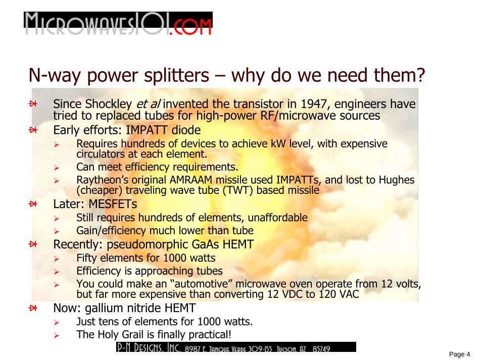
N-way power splitters – why do we need them?Since Shockley et al invented the transistor in 1947, engineers have tried to replaced tubes for high-power RF/microwave sourcesEarly efforts: IMPATT diode
Requires hundreds of devices to achieve kW level, with expensivecirculators at each element.Can meet efficiency requirements.Raytheon’s original AMRAAM missile used IMPATTs, and lost to Hughes (cheaper) traveling wave tube (TWT) based missile
Later: MESFETsStill requires hundreds of elements, unaffordableGain/efficiency much lower than tube
Recently: pseudomorphic GaAs HEMTFifty elements for 1000 wattsEfficiency is approaching tubesYou could make an “automotive” microwave oven operate from 12 volts, but far more expensive than converting 12 VDC to 120 VAC
Now: gallium nitride HEMTJust tens of elements for 1000 watts.The Holy Grail is finally practical!
5
Page 5
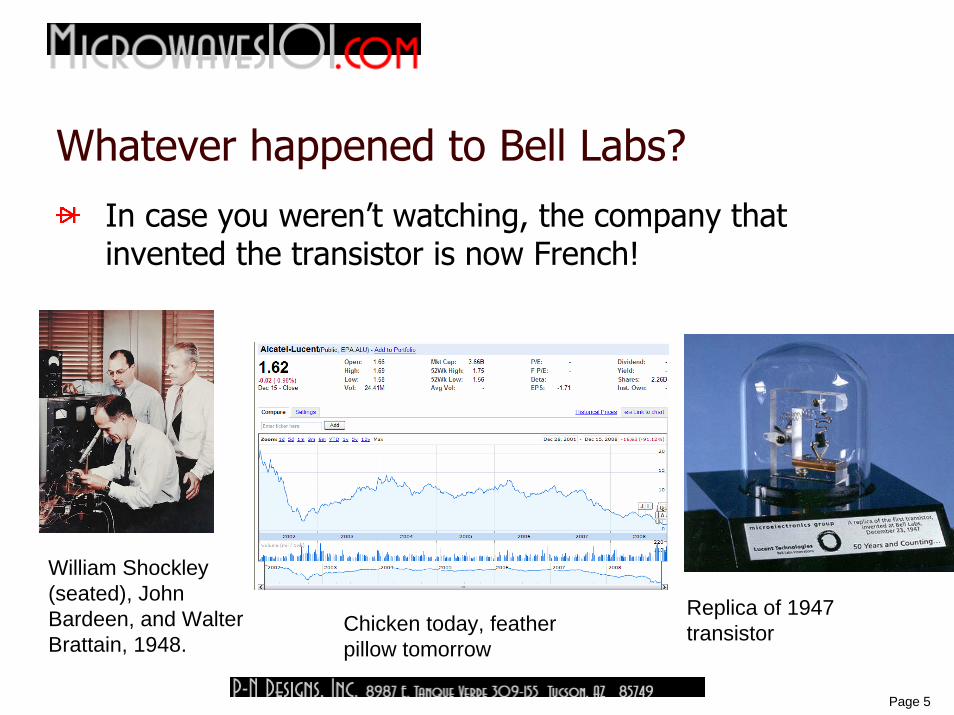
Whatever happened to Bell Labs?
William Shockley (seated), John Bardeen, and Walter Brattain, 1948.
Replica of 1947 transistor
In case you weren’t watching, the company that invented the transistor is now French!
Chicken today, feather pillow tomorrow
6
Page 6
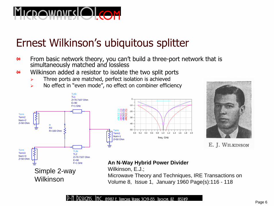
Ernest Wilkinson’s ubiquitous splitterFrom basic network theory, you can’t build a three-port network that is simultaneously matched and losslessWilkinson added a resistor to isolate the two split ports
Three ports are matched, perfect isolation is achievedNo effect in “even mode”, no effect on combiner efficiency
An N-Way Hybrid Power DividerWilkinson, E.J.;Microwave Theory and Techniques, IRE Transactions onVolume 8, Issue 1, January 1960 Page(s):116 - 118
TermTerm3
Z=50 OhmNum=3
TermTerm2
Z=50 OhmNum=2
TermTerm1
Z=50 OhmNum=1
TLINTL2
F=1 GHzE=90Z=70.7107 Ohm
TLINTL1
F=1 GHzE=90Z=70.7107 Ohm
RR2R=100 Ohm
Simple 2-way Wilkinson
0.2 0.4 0.6 0.8 1.0 1.2 1.4 1.6 1.80.0 2.0
-40
-30
-20
-10
-50
0
freq, GHz
dB(S
(2,2
))dB
(S(3
,2))
dB(S
(1,1
))dB
(S(2
,1))

7
Page 7
Ernest Wilkinson’s ubiquitous splitter continued
The original paper was for an N-way splitterRequires a “star resistor” to terminate all of the portsCan’t make greater than N=2 layout in two dimensionsSymmetry can be a cruel master!
8
Page 8
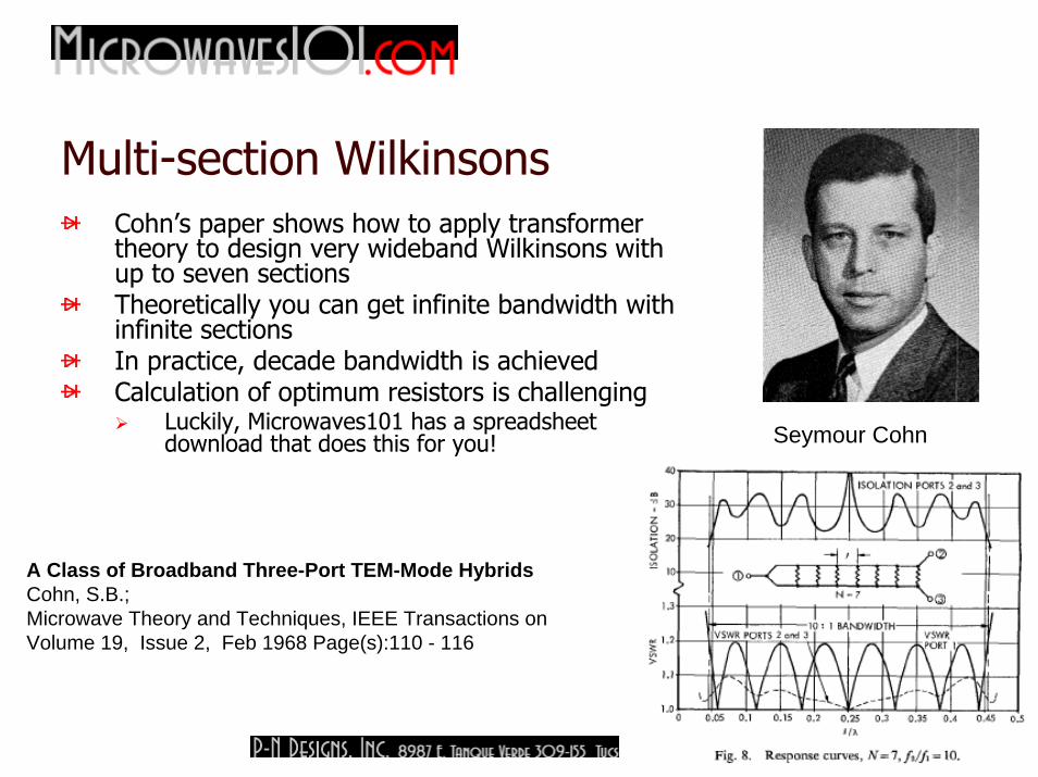
Multi-section WilkinsonsCohn’s paper shows how to apply transformer theory to design very wideband Wilkinsons with up to seven sectionsTheoretically you can get infinite bandwidth with infinite sectionsIn practice, decade bandwidth is achievedCalculation of optimum resistors is challenging
Luckily, Microwaves101 has a spreadsheet download that does this for you!
Seymour CohnA Class of Broadband Three-Port TEM-Mode HybridsCohn, S.B.;Microwave Theory and Techniques, IEEE Transactions onVolume 19, Issue 2, Feb 1968 Page(s):110 - 116
Seymour Cohn
9
Page 9
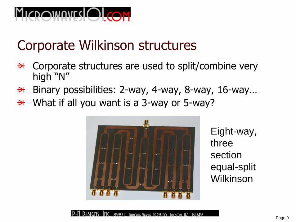
Corporate Wilkinson structuresCorporate structures are used to split/combine very high “N”Binary possibilities: 2-way, 4-way, 8-way, 16-way…What if all you want is a 3-way or 5-way?
Eight-way, three section equal-split Wilkinson
10
Page 10
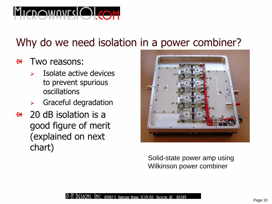
Why do we need isolation in a power combiner?
Two reasons:Isolate active devices to prevent spurious oscillationsGraceful degradation
20 dB isolation is a good figure of merit (explained on next chart)
Solid-state power amp using Wilkinson power combiner
11
Page 11
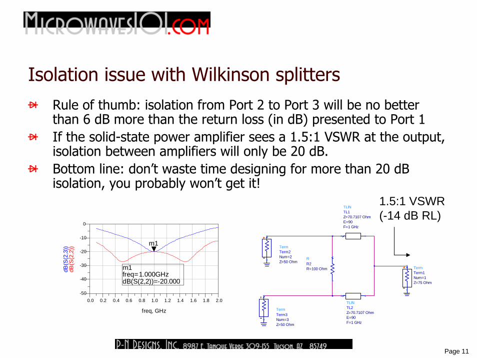
Isolation issue with Wilkinson splittersRule of thumb: isolation from Port 2 to Port 3 will be no betterthan 6 dB more than the return loss (in dB) presented to Port 1If the solid-state power amplifier sees a 1.5:1 VSWR at the output, isolation between amplifiers will only be 20 dB.Bottom line: don’t waste time designing for more than 20 dB isolation, you probably won’t get it!
TermTerm1
Z=75 OhmNum=1
TLINTL2
F=1 GHzE=90Z=70.7107 Ohm
TLINTL1
F=1 GHzE=90Z=70.7107 Ohm
RR2R=100 Ohm
TermTerm3
Z=50 OhmNum=3
TermTerm2
Z=50 OhmNum=2
0.2 0.4 0.6 0.8 1.0 1.2 1.4 1.6 1.80.0 2.0
-40
-30
-20
-10
-50
0
freq, GHz
dB(S
(2,2
))
m1
dB(S
(2,3
))
m1freq=dB(S(2,2))=-20.000
1.000GHz
1.5:1 VSWR (-14 dB RL)
12
Page 12
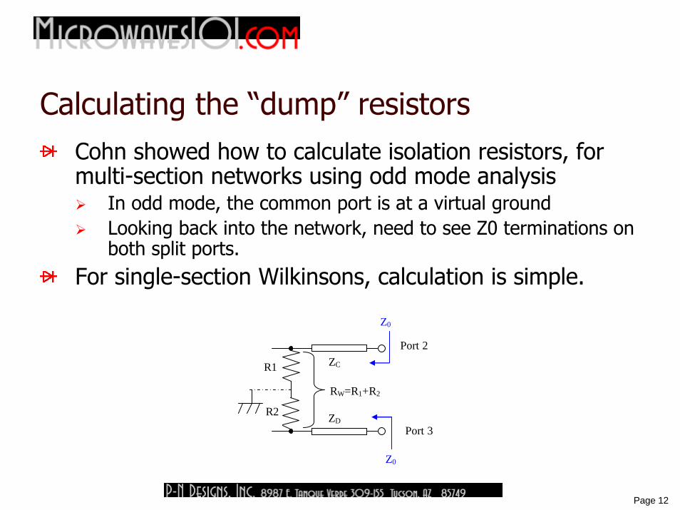
Calculating the “dump” resistorsCohn showed how to calculate isolation resistors, for multi-section networks using odd mode analysis
In odd mode, the common port is at a virtual groundLooking back into the network, need to see Z0 terminations on both split ports.
For single-section Wilkinsons, calculation is simple.
R1
R2
Port 3
RW=R1+R2
ZD
ZC Port 2
Z0
Z0
13
Page 13
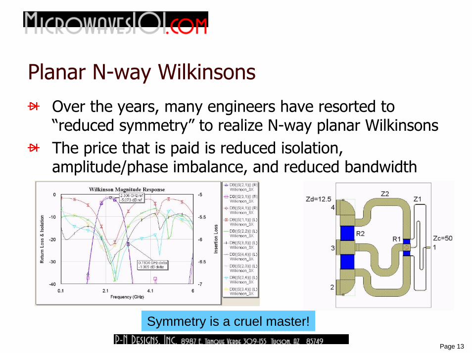
Planar N-way Wilkinsons
Over the years, many engineers have resorted to “reduced symmetry” to realize N-way planar WilkinsonsThe price that is paid is reduced isolation, amplitude/phase imbalance, and reduced bandwidth
Symmetry is a cruel master!
14
Page 14
Wilkinson and Cohn are Hall of Famers!
Microwaves101 Hall of Fame candidates must have made at least one truly great contribution to microwave engineering.
List starts with Napier – inventor of logarithms!Currently ends with Herb Kroemer, inventor of the HBTFaraday, Maxwell, Hertz, Lange, Wilkinson, and many others are in between
Not a day goes by when the name “Wilkinson” is not used in the microwave industryCohn wrote a ton of IEEE papers that are as relevant today as when he wrote them 50+ years ago
15
Page 15
Unequal-split Wilkinson reference
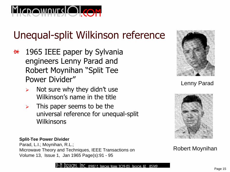
1965 IEEE paper by Sylvania engineers Lenny Parad and Robert Moynihan “Split Tee Power Divider”
Not sure why they didn’t use Wilkinson’s name in the titleThis paper seems to be the universal reference for unequal-split Wilkinsons
Split-Tee Power DividerParad, L.I.; Moynihan, R.L.;Microwave Theory and Techniques, IEEE Transactions onVolume 13, Issue 1, Jan 1965 Page(s):91 - 95
Robert Moynihan
Lenny Parad
16
Page 16
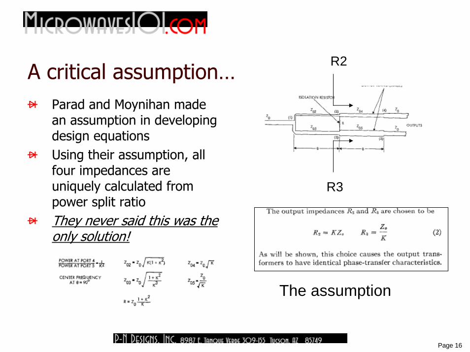
A critical assumption…Parad and Moynihan made an assumption in developing design equationsUsing their assumption, all four impedances are uniquely calculated from power split ratioThey never said this was the only solution!
R2
R3
The assumption
17
Page 17
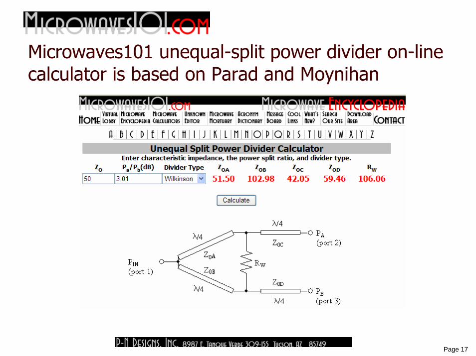
Microwaves101 unequal-split power divider on-line calculator is based on Parad and Moynihan
18
Page 18
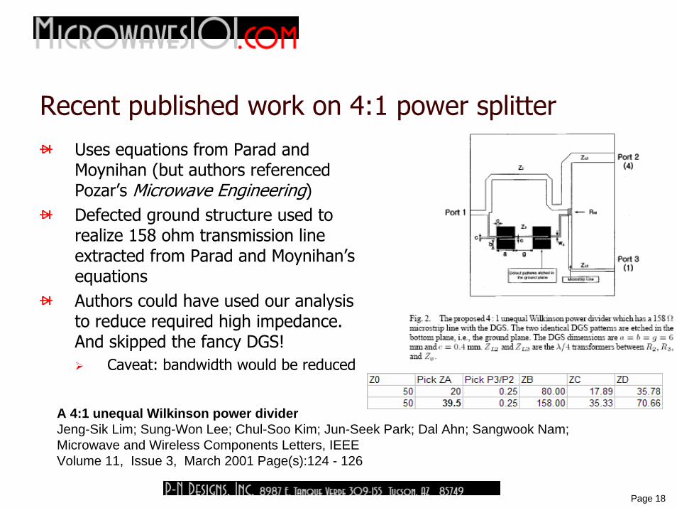
Recent published work on 4:1 power splitterUses equations from Parad and Moynihan (but authors referenced Pozar’s Microwave Engineering)Defected ground structure used to realize 158 ohm transmission line extracted from Parad and Moynihan’s equationsAuthors could have used our analysis to reduce required high impedance. And skipped the fancy DGS!
Caveat: bandwidth would be reduced
A 4:1 unequal Wilkinson power dividerJeng-Sik Lim; Sung-Won Lee; Chul-Soo Kim; Jun-Seek Park; Dal Ahn; Sangwook Nam;Microwave and Wireless Components Letters, IEEEVolume 11, Issue 3, March 2001 Page(s):124 - 126

19
Page 19
New look at the problemThere are just three RF criteria that must be met:ZA’ in parallel with ZB’ must equal Z0 for impedance matchBecause the voltage at the input node is the same looking into each arm. power split is proportional to RF current split, and will be inversely proportional to ratio of impedances ZA’/ZB’Voltage across isolation resistor has to be zero, when power is applied from common port. In order for this to happen, the impedance ratio ZA’/ZB’ must be maintained through first legs of the splitter.
ZA'
P3
(port 3)
PIN
(port 1) RW
ZD
ZC
ΖΒ
ZΑ
P2
(port 2)
ZB'
ZC'
ZD'
23
0
023
'
'
PPZZ
ZPPZ
D
C
=
⋅=
''''
0BA
BA
ZZZZZ+⋅
=
There’s a better explanation at Microwaves101.com!
20
Page 20
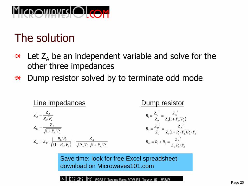
The solution
Let ZA be an independent variable and solve for the other three impedancesDump resistor solved by to terminate odd mode
( ) 232323
23
23
23
11
1
PPPPZ
PPPP
ZZ
PPZ
Z
PPZ
Z
ABD
AC
AB
+=
+⋅=
+=
=( )
( )
230
2
21
23230
2
0
2
2
230
2
0
2
1
1
1
PPZZRRR
PPPPZZ
ZZR
PPZZ
ZZR
AW
AD
AC
=+=
+==
+==
Line impedances Dump resistor
Save time: look for free Excel spreadsheet download on Microwaves101.com

21
Page 21
Now you have a choice!
Split ratio 2:1 (67%/33%)ZA=51.1 ohms is Parad and Moynihan’s resultZA=59.46 ohms represents max flat transformation (more about that later)ZA=40 ohms makes other line impedances easier to achieve− Highest impedance (ZB) is 80 ohms, Parad and Moynihan would
require 103 ohms
22
Page 22
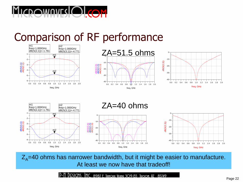
Comparison of RF performanceZA=51.5 ohms
0.2 0.4 0.6 0.8 1.0 1.2 1.4 1.6 1.80.0 2.0
-5
-4
-3
-2
-6
-1
freq, GHz
dB(S
(2,1
))
m1
dB(S
(3,1
))
m2
m1freq=dB(S(2,1))=-1.761
1.000GHzm2freq=dB(S(3,1))=-4.771
1.000GHz
0.2 0.4 0.6 0.8 1.0 1.2 1.4 1.6 1.80.0 2.0
-30
-20
-10
-40
0
freq, GHz
dB(S
(1,1
))dB
(S(2
,2))
dB(S
(3,3
))
0.2 0.4 0.6 0.8 1.0 1.2 1.4 1.6 1.80.0 2.0
-30
-20
-10
-40
0
freq, GHz
dB(S
(2,3
))
0.2 0.4 0.6 0.8 1.0 1.2 1.4 1.6 1.80.0 2.0
-5
-4
-3
-2
-6
-1
freq, GHz
dB(S
(2,1
))
m1
dB(S
(3,1
))
m2
m1freq=dB(S(2,1))=-1.761
1.000GHzm2freq=dB(S(3,1))=-4.771
1.000GHz
0.2 0.4 0.6 0.8 1.0 1.2 1.4 1.6 1.80.0 2.0
-30
-20
-10
-40
0
freq, GHz
dB(S
(1,1
))dB
(S(2
,2))
dB(S
(3,3
))
0.2 0.4 0.6 0.8 1.0 1.2 1.4 1.6 1.80.0 2.0
-30
-20
-10
-40
0
freq, GHz
dB(S
(2,3
))
ZA=40 ohms
ZA=40 ohms has narrower bandwidth, but it might be easier to manufacture.At least we now have that tradeoff!

23
Page 23
Robots versus Dinosaurs?Most people will provide an immediate answer and backup reasonsBut we’re engineers!
If someone asks you a technical question, you should establish critical parameters before you offer an answerWhat robots? Hollywood? U of A? Toys?Which dinosaurs? Aren’t they all dead? How many?What do we mean by “win?”
Before you answer, ask questions, develop a model, run a test case, gather and interpret data

24
Page 24
Robots versus Dinosaurs – possible data point?
Here at U of A, there are certainly some robots we could use…Could we borrow one for a little demonstration?
What’s the closest thing we have to a dinosaur in Tucson? Perhaps a Gila monster?How can we get them to fight? Tape a ham sandwich to the robot?

25
Page 25
Robots easily win Google search
Robot images found by Google: 16,000,000Dinosaurs: 1,600,000

26
Page 26
Apartment for rent!On North Park, front unit of duplex
1.6 miles from where you are sitting!
900 square feet 2BR 1BAEntirely new kitchen!
Gas stoveWasher and drier includedPolished concrete floor
Gas heat, evap coolingLarge fenced/shaded yard$800/month/all utilities includedAvailable January 15, 2009Contact Principalpropertymanagement.com if interested
Trust me, this is relevant!

27
Page 27
Robots versus Dinosaurs – Ground ZeroInspiration for title of this talk came from neighbor on Park Street
U of A sophomore “Nick”Beer pong table in garage, labeled “robots” on one side, “dinosaurs” on the otherNot sure which team is winning, sometimes a third team “cops” shuts down the game
For rentRobots versus Dinosaurs decided here
28
Page 28
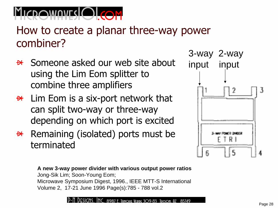
How to create a planar three-way power combiner?
Someone asked our web site about using the Lim Eom splitter to combine three amplifiersLim Eom is a six-port network that can split two-way or three-way depending on which port is excitedRemaining (isolated) ports must be terminated
A new 3-way power divider with various output power ratiosJong-Sik Lim; Soon-Young Eom;Microwave Symposium Digest, 1996., IEEE MTT-S InternationalVolume 2, 17-21 June 1996 Page(s):785 - 788 vol.2
3-way 2-wayinput input
29
Page 29
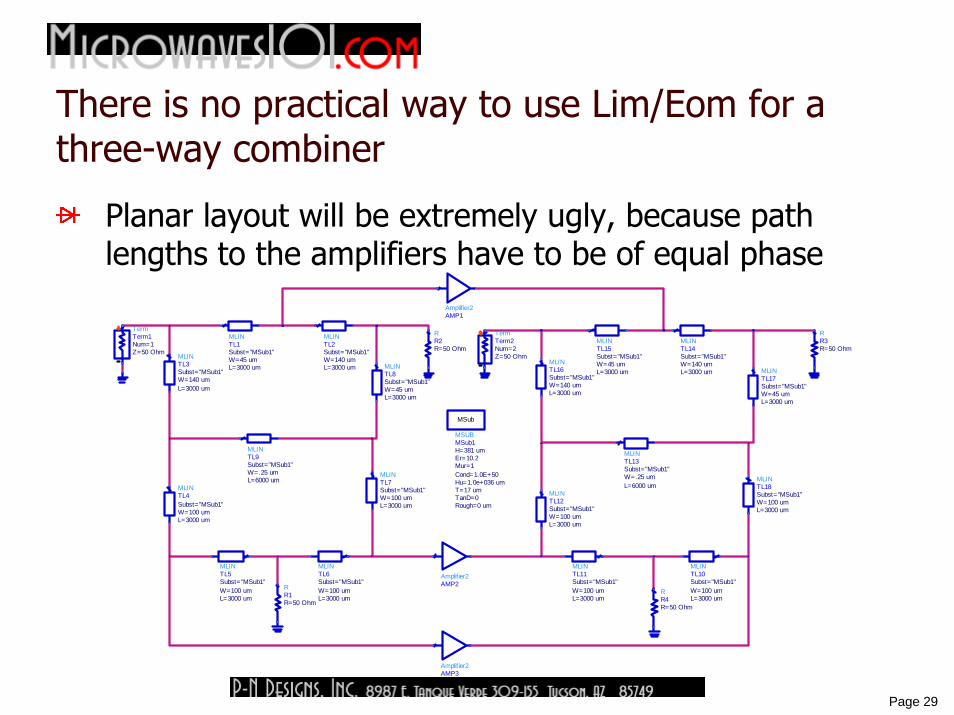
There is no practical way to use Lim/Eom for a three-way combiner
Planar layout will be extremely ugly, because path lengths to the amplifiers have to be of equal phase
Amplifier2AMP3
Amplifier2AMP2
Amplifier2AMP1
RR3R=50 Ohm
MLINTL1
L=3000 umW=45 umSubst="MSub1"
TermTerm1
Z=50 OhmNum=1
MLINTL4
L=3000 umW=100 umSubst="MSub1"
MLINTL5
L=3000 umW=100 umSubst="MSub1"
MLINTL3
L=3000 umW=140 umSubst="MSub1"
MSUBMSub1
Rough=0 umTanD=0T=17 umHu=1.0e+036 umCond=1.0E+50Mur=1Er=10.2H=381 um
MSub
MLINTL6
L=3000 umW=100 umSubst="MSub1"
MLINTL12
L=3000 umW=100 umSubst="MSub1"
MLINTL10
L=3000 umW=100 umSubst="MSub1"
MLINTL11
L=3000 umW=100 umSubst="MSub1"
MLINTL15
L=3000 umW=45 umSubst="MSub1"
MLINTL14
L=3000 umW=140 umSubst="MSub1"
MLINTL7
L=3000 umW=100 umSubst="MSub1"
MLINTL8
L=3000 umW=45 umSubst="MSub1"
MLINTL9
L=6000 umW=.25 umSubst="MSub1"
RR1R=50 Ohm
RR2R=50 Ohm
MLINTL2
L=3000 umW=140 umSubst="MSub1"
TermTerm2
Z=50 OhmNum=2
MLINTL18
L=3000 umW=100 umSubst="MSub1"
MLINTL17
L=3000 umW=45 umSubst="MSub1"
MLINTL16
L=3000 umW=140 umSubst="MSub1"
MLINTL13
L=6000 umW=.25 umSubst="MSub1"
RR4R=50 Ohm
30
Page 30
Jack’s idea
Create a planar, equal three-way split using an unequal 67%/33% splitter, then split the 67% port into two signals.This may not be novel, but Jack and I have developed the technique beyond what you can find in IEEE literatureWe won’t fully cover the topic tonight, but if you are interested visit Microwaves101.com and look up ”Kouzoujian splitter”, or just Google it
Check back in a few months, we aren’t done!
31
Page 31
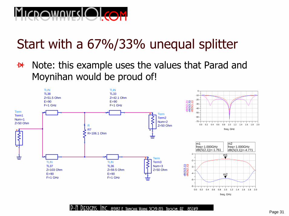
Start with a 67%/33% unequal splitter
Note: this example uses the values that Parad and Moynihan would be proud of!
TLINTL33
F=1 GHzE=90Z=42.1 Ohm
RR7R=106.1 Ohm
TLINTL36
F=1 GHzE=90Z=59.5 Ohm
TLINTL37
F=1 GHzE=90Z=103 Ohm
TLINTL38
F=1 GHzE=90Z=51.5 Ohm
TermTerm3
Z=50 OhmNum=3
TermTerm2
Z=50 OhmNum=2
TermTerm1
Z=50 OhmNum=1
0.2 0.4 0.6 0.8 1.0 1.2 1.4 1.6 1.80.0 2.0
-5
-4
-3
-2
-6
-1
freq, GHz
dB(S
(2,1
))
m1
dB(S
(3,1
))
m2
m1freq=dB(S(2,1))=-1.761
1.000GHzm2freq=dB(S(3,1))=-4.771
1.000GHz
0.2 0.4 0.6 0.8 1.0 1.2 1.4 1.6 1.80.0 2.0
-60
-50
-40
-30
-20
-10
-70
0
freq, GHz
dB(S
(1,1
))dB
(S(3
,3))
dB(S
(2,2
))

32
Page 32
Add a second stage, by splitting the low-impedance arm and adding a second isolation resistor
Perfect three-way amplitude (and phase) balance and infinite isolation at band center (ideally) are achieved
RR8R=100 Ohm
RR7R=106.1 Ohm
TLINTL36
F=1 GHzE=90Z=59.5 Ohm
TLINTL33
F=1 GHzE=90Z=59.5 Ohm
TLINTL39
F=1 GHzE=90Z=59.5 Ohm
TLINTL37
F=1 GHzE=90Z=103 Ohm
TLINTL38
F=1 GHzE=90Z=51.5 Ohm
TermTerm4
Z=50 OhmNum=4
TermTerm2
Z=50 OhmNum=2
TermTerm3
Z=50 OhmNum=3
TermTerm1
Z=50 OhmNum=1
0.2 0.4 0.6 0.8 1.0 1.2 1.4 1.6 1.80.0 2.0
-60
-40
-20
-80
0
freq, GHz
dB(S
(1,1
))dB
(S(2
,2))
dB(S
(3,3
))dB
(S(2
,3))
dB(S
(3,4
))
0.2 0.4 0.6 0.8 1.0 1.2 1.4 1.6 1.80.0 2.0
-6.0
-5.8
-5.6
-5.4
-5.2
-5.0
-4.8
-6.2
-4.6
freq, GHz
dB(S
(2,1
))dB
(S(3
,1))
dB(S
(4,1
))
All arms receive -4.77 dB referenced to input
33
Page 33
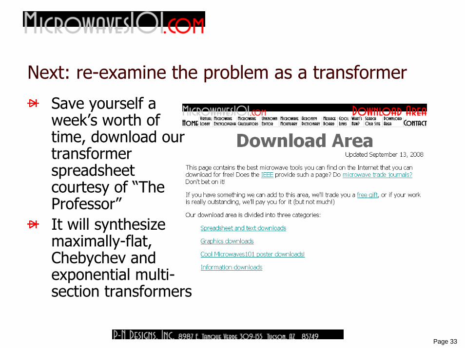
Next: re-examine the problem as a transformer
Save yourself a week’s worth of time, download our transformer spreadsheet courtesy of “The Professor”It will synthesize maximally-flat, Chebychev and exponential multi-section transformers
34
Page 34
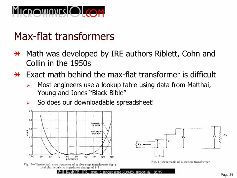
Max-flat transformers
Math was developed by IRE authors Riblett, Cohn and Collin in the 1950sExact math behind the max-flat transformer is difficult
Most engineers use a lookup table using data from Matthai, Young and Jones “Black Bible”So does our downloadable spreadsheet!
35
Page 35
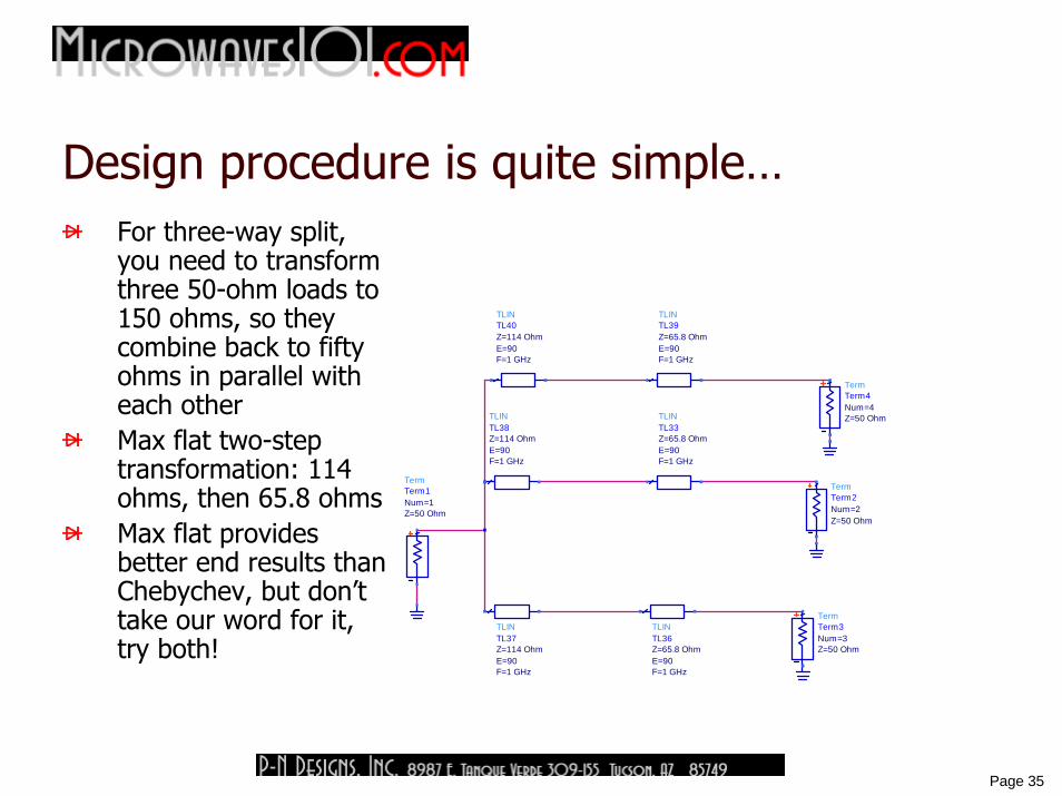
Design procedure is quite simple…For three-way split, you need to transform three 50-ohm loads to 150 ohms, so they combine back to fifty ohms in parallel with each otherMax flat two-step transformation: 114 ohms, then 65.8 ohmsMax flat provides better end results than Chebychev, but don’t take our word for it, try both!
TLINTL36
F=1 GHzE=90Z=65.8 Ohm
TLINTL33
F=1 GHzE=90Z=65.8 Ohm
TLINTL39
F=1 GHzE=90Z=65.8 Ohm
TLINTL37
F=1 GHzE=90Z=114 Ohm
TLINTL38
F=1 GHzE=90Z=114 Ohm
TLINTL40
F=1 GHzE=90Z=114 Ohm
TermTerm4
Z=50 OhmNum=4
TermTerm2
Z=50 OhmNum=2
TermTerm3
Z=50 OhmNum=3
TermTerm1
Z=50 OhmNum=1

36
Page 36
Next, combine two arms
Combining two arms in parallel requires halving their impedance
Two 114 ohm lines become single 57 ohm lineInput still sees maximally-flat impedance match
TLINTL38
F=1 GHzE=90Z=57 Ohm
TLINTL36
F=1 GHzE=90Z=65.8 Ohm
TLINTL33
F=1 GHzE=90Z=65.8 Ohm
TLINTL39
F=1 GHzE=90Z=65.8 Ohm
TLINTL37
F=1 GHzE=90Z=114 Ohm
TermTerm4
Z=50 OhmNum=4
TermTerm2
Z=50 OhmNum=2
TermTerm3
Z=50 OhmNum=3
TermTerm1
Z=50 OhmNum=1
37
Page 37
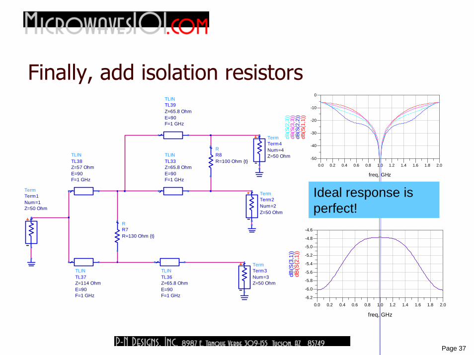
Finally, add isolation resistors
RR8R=100 Ohm {t}
RR7R=130 Ohm {t}
TLINTL38
F=1 GHzE=90Z=57 Ohm
TLINTL36
F=1 GHzE=90Z=65.8 Ohm
TLINTL33
F=1 GHzE=90Z=65.8 Ohm
TLINTL39
F=1 GHzE=90Z=65.8 Ohm
TLINTL37
F=1 GHzE=90Z=114 Ohm
TermTerm4
Z=50 OhmNum=4
TermTerm2
Z=50 OhmNum=2
TermTerm3
Z=50 OhmNum=3
TermTerm1
Z=50 OhmNum=1
0.2 0.4 0.6 0.8 1.0 1.2 1.4 1.6 1.80.0 2.0
-40
-30
-20
-10
-50
0
freq, GHz
dB(S
(1,1
))dB
(S(2
,2))
dB(S
(3,3
))dB
(S(2
,3))
0.2 0.4 0.6 0.8 1.0 1.2 1.4 1.6 1.80.0 2.0
-6.0
-5.8
-5.6
-5.4
-5.2
-5.0
-4.8
-6.2
-4.6
freq, GHz
dB(S
(2,1
))dB
(S(3
,1))
Ideal response is perfect!
38
Page 38
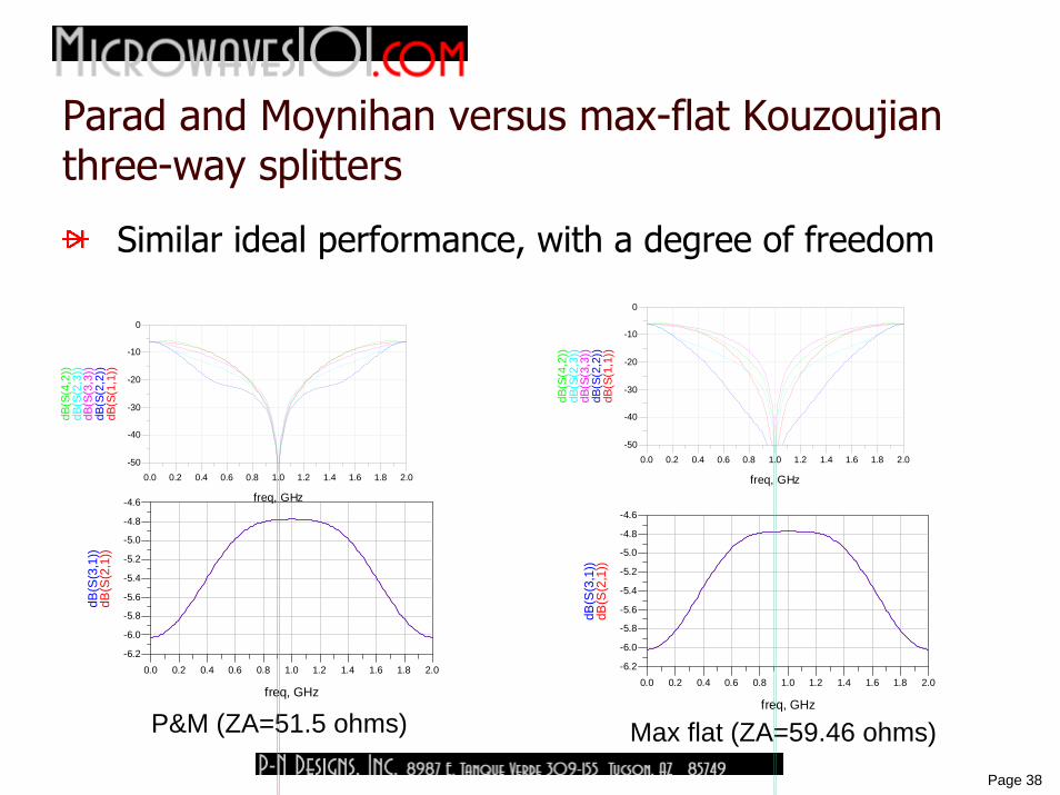
Parad and Moynihan versus max-flat Kouzoujian three-way splitters
Similar ideal performance, with a degree of freedom
0.2 0.4 0.6 0.8 1.0 1.2 1.4 1.6 1.80.0 2.0
-6.0
-5.8
-5.6
-5.4
-5.2
-5.0
-4.8
-6.2
-4.6
freq, GHz
dB(S
(2,1
))dB
(S(3
,1))
0.2 0.4 0.6 0.8 1.0 1.2 1.4 1.6 1.80.0 2.0
-6.0
-5.8
-5.6
-5.4
-5.2
-5.0
-4.8
-6.2
-4.6
freq, GHz
dB(S
(2,1
))dB
(S(3
,1))
Max flat (ZA=59.46 ohms)P&M (ZA=51.5 ohms)
0.2 0.4 0.6 0.8 1.0 1.2 1.4 1.6 1.80.0 2.0
-40
-30
-20
-10
-50
0
freq, GHz
dB(S
(1,1
))dB
(S(2
,2))
dB(S
(3,3
))dB
(S(2
,3))
dB(S
(4,2
))
0.2 0.4 0.6 0.8 1.0 1.2 1.4 1.6 1.80.0 2.0
-40
-30
-20
-10
-50
0
freq, GHz
dB(S
(1,1
))dB
(S(2
,2))
dB(S
(3,3
))dB
(S(2
,3))
dB(S
(4,2
))
39
Page 39
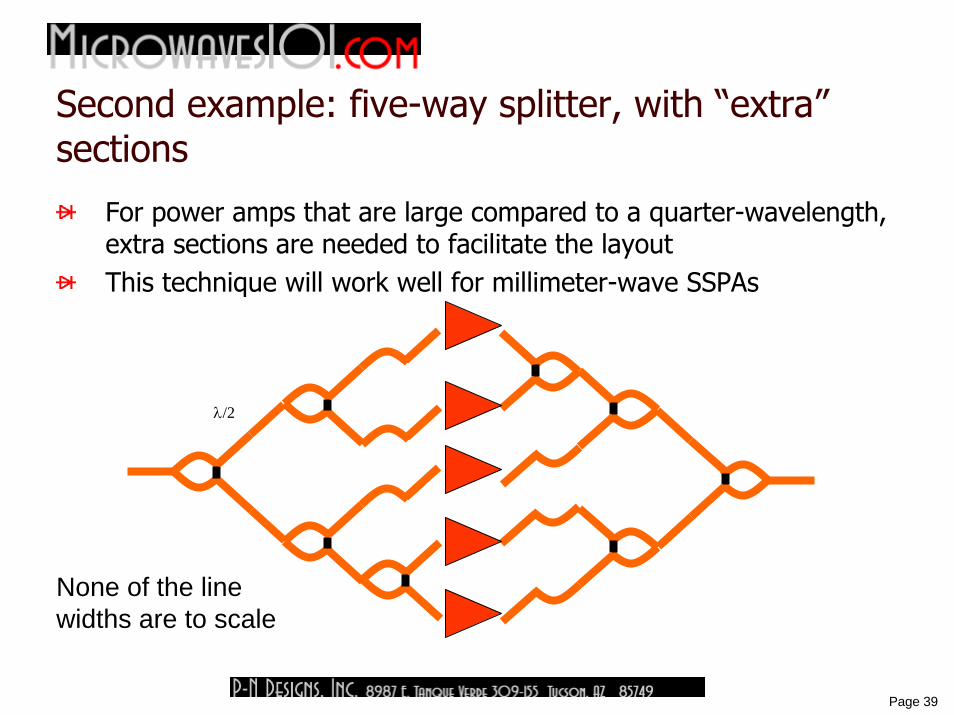
Second example: five-way splitter, with “extra” sections
For power amps that are large compared to a quarter-wavelength, extra sections are needed to facilitate the layoutThis technique will work well for millimeter-wave SSPAs
λ/2
None of the line widths are to scale
40
Page 40
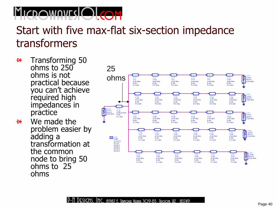
Start with five max-flat six-section impedance transformers
Transforming 50 ohms to 250 ohms is not practical because you can’t achieve required high impedances in practiceWe made the problem easier by adding a transformation at the common node to bring 50 ohms to 25 ohms
TermTerm6
Z=50 OhmNum=6
TermTerm5
Z=50 OhmNum=5
TermTerm4
Z=50 OhmNum=4
TLINTL47
F=1 GHzE=90Z=Z1 Ohm
TLINTL56
F=1 GHzE=90Z=Z5 Ohm
TLINTL55
F=1 GHzE=90Z=Z4 Ohm
TLINTL54
F=1 GHzE=90Z=Z6 Ohm
TLINTL53
F=1 GHzE=90Z=Z1 Ohm
TLINTL52
F=1 GHzE=90Z=Z2 Ohm
TLINTL51
F=1 GHzE=90Z=Z3 Ohm
TLINTL50
F=1 GHzE=90Z=Z5 Ohm
TLINTL49
F=1 GHzE=90Z=Z4 Ohm
TLINTL48
F=1 GHzE=90Z=Z6 Ohm
TLINTL46
F=1 GHzE=90Z=Z2 Ohm
TLINTL45
F=1 GHzE=90Z=Z3 Ohm
TLINTL44
F=1 GHzE=90Z=Z5 Ohm
TLINTL43
F=1 GHzE=90Z=Z4 Ohm
TLINTL42
F=1 GHzE=90Z=Z6 Ohm
TLINTL41
F=1 GHzE=90Z=Z1 Ohm
TLINTL40
F=1 GHzE=90Z=Z2 Ohm
TLINTL39
F=1 GHzE=90Z=Z3 Ohm
TLINTL38
F=1 GHzE=90Z=Z5 Ohm
TLINTL37
F=1 GHzE=90Z=Z4 Ohm
TLINTL36
F=1 GHzE=90Z=Z6 Ohm
TLINTL35
F=1 GHzE=90Z=Z1 Ohm
TLINTL34
F=1 GHzE=90Z=Z2 Ohm
TLINTL33
F=1 GHzE=90Z=Z3 Ohm
TLINTL2
F=1 GHzE=90Z=Z3 Ohm
TLINTL22
F=1 GHzE=90Z=Z2 Ohm
TLINTL1
F=1 GHzE=90Z=Z1 Ohm
VARVAR5
Z6=50.9Z5=55.8Z4=69.3Z3=90.2Z2=112Z1=122.8
EqnVar
TLINTL32
F=1 GHzE=90Z=35.35 Ohm
TermTerm1
Z=50 OhmNum=1
TermTerm3
Z=50 OhmNum=3
TermTerm2
Z=50 OhmNum=2
TLINTL16
F=1 GHzE=90Z=Z6 Ohm
TLINTL27
F=1 GHzE=90Z=Z4 Ohm
TLINTL3
F=1 GHzE=90Z=Z5 Ohm
25 ohms
41
Page 41
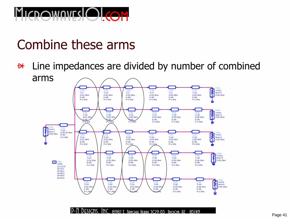
Combine these arms
Line impedances are divided by number of combined arms
TermTerm6
Z=50 OhmNum=6
TermTerm5
Z=50 OhmNum=5
TermTerm4
Z=50 OhmNum=4
TLINTL47
F=1 GHzE=90Z=Z1 Ohm
TLINTL56
F=1 GHzE=90Z=Z5 Ohm
TLINTL55
F=1 GHzE=90Z=Z4 Ohm
TLINTL54
F=1 GHzE=90Z=Z6 Ohm
TLINTL53
F=1 GHzE=90Z=Z1 Ohm
TLINTL52
F=1 GHzE=90Z=Z2 Ohm
TLINTL51
F=1 GHzE=90Z=Z3 Ohm
TLINTL50
F=1 GHzE=90Z=Z5 Ohm
TLINTL49
F=1 GHzE=90Z=Z4 Ohm
TLINTL48
F=1 GHzE=90Z=Z6 Ohm
TLINTL46
F=1 GHzE=90Z=Z2 Ohm
TLINTL45
F=1 GHzE=90Z=Z3 Ohm
TLINTL44
F=1 GHzE=90Z=Z5 Ohm
TLINTL43
F=1 GHzE=90Z=Z4 Ohm
TLINTL42
F=1 GHzE=90Z=Z6 Ohm
TLINTL41
F=1 GHzE=90Z=Z1 Ohm
TLINTL40
F=1 GHzE=90Z=Z2 Ohm
TLINTL39
F=1 GHzE=90Z=Z3 Ohm
TLINTL38
F=1 GHzE=90Z=Z5 Ohm
TLINTL37
F=1 GHzE=90Z=Z4 Ohm
TLINTL36
F=1 GHzE=90Z=Z6 Ohm
TLINTL35
F=1 GHzE=90Z=Z1 Ohm
TLINTL34
F=1 GHzE=90Z=Z2 Ohm
TLINTL33
F=1 GHzE=90Z=Z3 Ohm
TLINTL2
F=1 GHzE=90Z=Z3 Ohm
TLINTL22
F=1 GHzE=90Z=Z2 Ohm
TLINTL1
F=1 GHzE=90Z=Z1 Ohm
VARVAR5
Z6=50.9Z5=55.8Z4=69.3Z3=90.2Z2=112Z1=122.8
EqnVar
TLINTL32
F=1 GHzE=90Z=35.35 Ohm
TermTerm1
Z=50 OhmNum=1
TermTerm3
Z=50 OhmNum=3
TermTerm2
Z=50 OhmNum=2
TLINTL16
F=1 GHzE=90Z=Z6 Ohm
TLINTL27
F=1 GHzE=90Z=Z4 Ohm
TLINTL3
F=1 GHzE=90Z=Z5 Ohm
42
Page 42
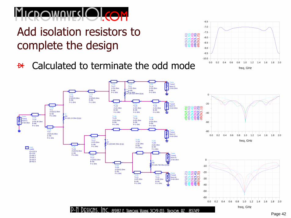
Add isolation resistors tocomplete the design
Calculated to terminate the odd mode
VARVAR5
Z6=50.9Z5=55.8Z4=69.3Z3=90.2Z2=112Z1=122.8
EqnVar
RR8R=103.749 Ohm {t} {o}
RR5R=103.13 Ohm {t} {o}
RR7R=120.845 Ohm {t} {o}
RR6R=120.132 Ohm {t} {o}
TLINTL32
F=1 GHzE=90Z=35.35 Ohm
TermTerm1
Z=50 OhmNum=1
TLINTL17
F=1 GHzE=90Z=Z3 Ohm
TermTerm6
Z=50 OhmNum=6
TermTerm5
Z=50 OhmNum=5
TermTerm4
Z=50 OhmNum=4
TermTerm3
Z=50 OhmNum=3
TermTerm2
Z=50 OhmNum=2
TLINTL26
F=1 GHzE=90Z=Z6 Ohm
TLINTL16
F=1 GHzE=90Z=Z6 Ohm
TLINTL9
F=1 GHzE=90Z=(Z1/3) Ohm
TLINTL2
F=1 GHzE=90Z=(Z3/2) Ohm
TLINTL19
F=1 GHzE=90Z=Z5 Ohm
TLINTL27
F=1 GHzE=90Z=Z4 Ohm
TLINTL11
F=1 GHzE=90Z=(Z3/2) Ohm
TLINTL22
F=1 GHzE=90Z=(Z2/2) Ohm
TLINTL28
F=1 GHzE=90Z=(Z4/2) Ohm
TLINTL25
F=1 GHzE=90Z=Z4 Ohm
TLINTL29
F=1 GHzE=90Z=Z6 Ohm
TLINTL20
F=1 GHzE=90Z=Z5 Ohm
TLINTL30
F=1 GHzE=90Z=Z6 Ohm
TLINTL31
F=1 GHzE=90Z=Z6 Ohm
TLINTL21
F=1 GHzE=90Z=Z5 Ohm
TLINTL23
F=1 GHzE=90Z=(Z2/3) Ohm
TLINTL18
F=1 GHzE=90Z=Z4 Ohm
TLINTL24
F=1 GHzE=90Z=Z5 Ohm
TLINTL3
F=1 GHzE=90Z=Z5 Ohm
TLINTL1
F=1 GHzE=90Z=(Z1/2) Ohm
0.2 0.4 0.6 0.8 1.0 1.2 1.4 1.6 1.80.0 2.0
-60
-40
-20
-80
0
freq, GHz
dB(S
(1,1
))dB
(S(2
,2))
dB(S
(3,3
))dB
(S(4
,4))
dB(S
(5,5
))dB
(S(6
,6))
0.2 0.4 0.6 0.8 1.0 1.2 1.4 1.6 1.80.0 2.0
-50
-40
-30
-20
-10
-60
0
freq, GHz
dB(S
(2,3
))dB
(S(3
,4))
dB(S
(4,5
))dB
(S(5
,6))
dB(S
(6,2
))
0.2 0.4 0.6 0.8 1.0 1.2 1.4 1.6 1.80.0 2.0
-9.5
-9.0
-8.5
-8.0
-7.5
-7.0
-10.0
-6.5
freq, GHz
dB(S
(1,2
))dB
(S(1
,3))
dB(S
(1,4
))dB
(S(1
,5))
dB(S
(1,6
))
43
Page 43
Why didn’t we write an IEEE article on this topic?
Microwaves101 is where we “published” this informationCompared to IEEE journals…
No membership fee required to read itNo need to wait for peer reviewEither way, we don’t get paid!
IEEE authors: feel free to reference our work!
The internet has forever changed what it means to “publish”
44
Page 44
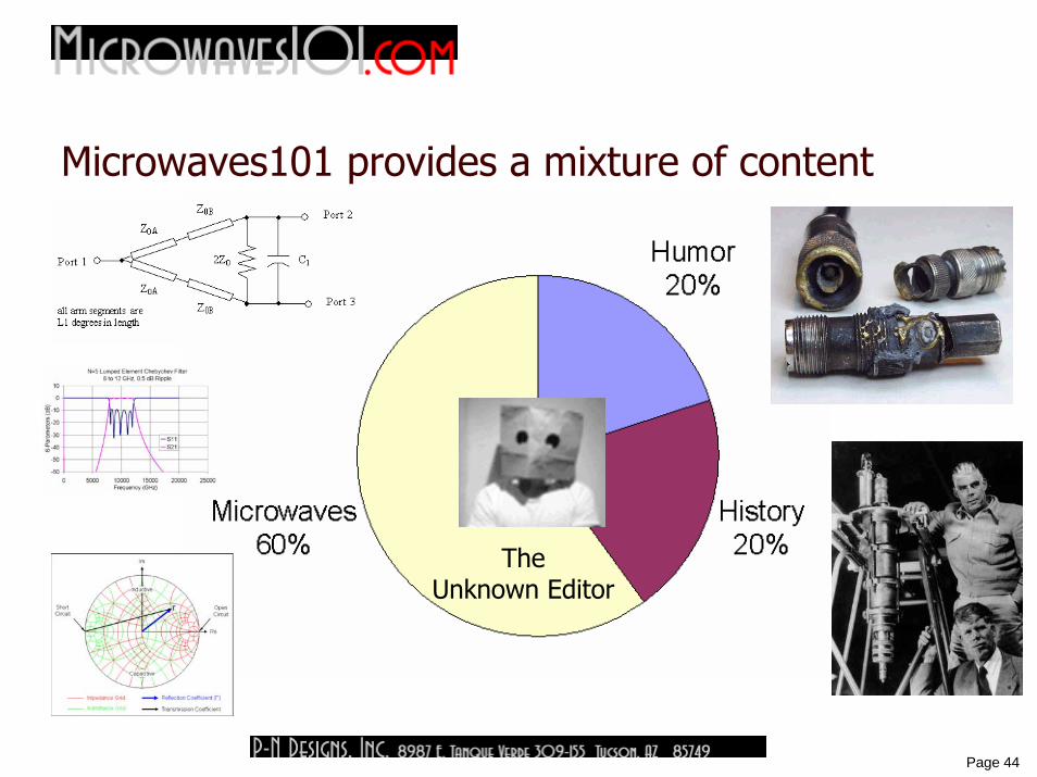
Microwaves101 provides a mixture of content
The Unknown Editor
45
Page 45
ConclusionsWhen someone asks your quick opinion, get further information before you offer an answer
Act like an engineer!Just because Parad and Moynihan “chose stegosaurus”, doesn’t mean you shouldn’t look at other dinosaurs
We recovered an independent variable for unequal-split WilkinsonsPlanar N-way Wilkinsons suffer from poor isolation and imbalance
Symmetry is a cruel master!We introduced a new type of N-way power splitter that can provide “odd” splits like N=3 and N=5
Perfect isolation is achieved in a compact planar layout
January 2009 issue of Microwaves and RF contains an in-depth interview with the Unknown Editor!
Thanks for staying awake if you managed to!