robust control of flexible high-speed rotors via...
TRANSCRIPT
Robust Control of Flexible High-Speed Rotors via Mixed Uncertainties
Bernd Riemann, Martin A. Sehr, Rudolf Sebastian Schittenhelm, and Stephan Rinderknecht
Abstract— Active vibration control for flexible high-speedrotors tends to be a particularly challenging problem due to theinfluence of gyroscopic terms, resulting in the need for speed-dependent system models. This paper addresses robust controlof such systems, using Linear Fractional Transformations(LFTs) for decoupling the system model into speed-dependentand -independent components in LFT feedback. Based on theresulting LFT decomposition, the speed-dependent terms areefficiently reduced in order and considered uncertain withrespect to the rotational speed of the shaft. The resultingperturbations are augmented by complex, additive uncertaintiesand explicitly used for control synthesis. Defining semi-modalperformance measures, the perturbed open-loop systems arewell-suited for mixed µ synthesis techniques. In particular,(D,G)-K and µ-K algorithm, both enabling explicit treatment ofmixed perturbations, are investigated in approaching the robustvibration attenuation problem across the range of operatingspeeds.
I. INTRODUCTION
Bending vibrations are a limiting factor in design ofnumerous industrial rotating machineries. For high-speedand high-precision applications, passive methods like bal-ancing or integration of additional damping elements suchas squeeze film dampers hit accuracy limits, especially whenmultiple resonance frequencies of a flexible rotor are withinits range of operation. In many such cases, unbalance isthe dominating excitation source of bending vibrations [12].Hence, the issue of active vibration control for flexible rotorsystems is investigated by numerous researchers.
Lots of publications on active rotor systems considerrotors supported by active magnetic bearings, as the ideaof active vibration control arises naturally in the presenceof active bearings [29]. Alternative concepts such as semi-active dampers (e.g. adaptive squeeze film dampers [5]) oractive bearings by means of ball bearings supported bypiezoelectric stack actuators have been developed in the lastdecades [20]. The latter option offers advantages in termsof high force generation at low phase lag and relatively lowweight. Usually, the actuators are located at the bearings,which are close to the nodes of the lower bending vibrationmodes, limiting their controllability. Further issues regardingpractical applications of piezoelectric stack actuators includehysteresis induced self-heating and demands on operating
B. Riemann, R. S. Schittenhelm, and S. Rinderknecht are with theInstitute for Mechatronic Systems, TU Darmstadt, Darmstadt, Germany(email: [email protected], [email protected],[email protected]).
M. A. Sehr was with the Institute for Mechatronic Systems, TU Darm-stadt, Darmstadt, Germany. He is now with the Department of Mechanicaland Aerospace Engineering, University of California, San Diego, La Jolla,USA (email: [email protected]).
conditions such as temperature range and load directions[26].
From a control synthesis point of view, the dynamics ofhigh-speed flexible rotors are time variant as gyroscopicterms depend on the shaft’s rotational speed. For increas-ing rotational speeds, the standstill eigenmodes and naturalfrequencies split up into so-called forward- and backwardwhirls, while only forward whirl modes are excited byunbalances [12]. Most publications on active rotor systemssubject to severe gyroscopic effects deploy linear controltechniques, either robust ones or such adaptive with respectto the shaft’s rotational speed. Adaptive feedforward controlschemes have resulted in remarkable performance, but inducerestrictions concerning stability analysis, local vs. global vi-bration attenuation, and the need for a signal that is correlatedwith the unbalance [15]. Adaptive feedback designs for high-speed rotors usually employ gain scheduling of Linear TimeInvariant (LTI) controllers, as stability and dynamics usingdirect nonlinear controllers are hard to predict [16]. Specialforms of such approaches, partially in combination withrobust control techniques, are being developed [17].
Robust control techniques allow the synthesis of con-trollers yielding guaranteed stability and performance at thecost of increased modeling effort, more involved optimiza-tions, and some design-induced degree of conservatism [21].New approaches via Linear Matrix Inequality (LMI) methodshave been suggested in recent years, for instance such addingrobustness to H2 controllers [6], although applications tohigh-speed rotors subject to severe gyroscopic effects arerare. Two established robust control techniques are H∞ andStructured Singular Value (SSV, µ) synthesis, both utilizedsuccessfully for actively reducing vibrations of rotor systems[11], [13]. For flexible high-speed rotors under significantgyroscopic influence, complex µ synthesis via D-K Iterations[8] has been shown to yield solid performance and robustnessproperties [24]. However, caused by its limitation to complexmodel perturbations, complex µ synthesis induces significantconservatism. In order to greatly reduce this design-inducedconservatism, the gyroscopic influence can be captured usinga real parametric uncertainty. Replacing this real perturbationelement by complex uncertainties, as done in [17], inducesa large degree of conservatism.
In this paper, the real perturbation capturing gyroscopiceffects is tackled employing mixed µ synthesis via (D,G)-K[32] and µ-K [27] Iterations, respectively. These approachesallow the explicit inclusion of real perturbations in un-certainty models, promising a non-conservative treatmentof flexible high-speed rotors. In section II, the nominalopen-loop model of a particular rotor test rig is described,
2013 European Control Conference (ECC)July 17-19, 2013, Zürich, Switzerland.
978-3-952-41734-8/©2013 EUCA 2343

including a brief introduction on rotordynamics. SectionIII provides a brief survey regarding the control synthesistechniques applied to the perturbed, augmented open-loopplant model introduced in section IV. Ultimately, the closed-loop results are summarized in section V.
II. NOMINAL PLANT MODEL
This section addresses a brief introduction on the dynamicsof flexible high-speed rotors, translating into an accurate low-order model of the concrete rotor test rig investigated in thispaper.
A. Test RigThe dynamics of a high-speed flexible rotor system are
varying according to the rotational speed Ω of the shaft, cap-tured in the linear equations of motion for the displacementsqi:
Mq + (D + ΩG)q + Sq = F. (1)
While mass matrix M , damping matrix D, and stiffnessmatrix S are constant symmetric matrices, respectively, theskew-symmetric gyroscopic matrix G is multiplied by Ω.This speed-dependency within the equations of motion re-sults in a shift of the system’s natural frequencies. While thegyroscopic matrix is commonly summarized as the productG∗ = ΩG, the notation used here translates naturally towardsthe inclusion of perturbations addressed in section IV. Forthe remainder of this paper, G shall denote the gyroscopicmatrix corresponding with a rotational speed of 1 rad/s.
The considered rotor system is a two disk flexible rotor,supported by a passive and an active piezoelectric bearing.The actual test rig is depicted in fig. 1, the construction ofthe active bearing being illustrated by fig. 2. The rotor isdesigned for significant exposure to gyroscopic effects andcapability of passing two resonance speeds below the DCmotor’s maximum speed of approximately 8,000 rpm.
Fig. 1. Test rig: (a) disk 1, (b) active bearing, (c) disk 2, (d) passivebearing, (e) DC-motor
The shift of natural frequencies caused by the skew-symmetric gyroscopic terms in (1) is displayed in fig. 3,employing a Campbell diagram. It can be seen within thisdiagram how, for increasing rotational speed Ω > 0, eachstandstill natural frequency splits up into a backward (de-scending branches) and a forward whirl frequency (ascendingbranches). Each of these pairs corresponds to eigenforms of
xy
Actuators
Ω
Fig. 2. Active bearing
similar shape, forward whirl modes rotating in the shaft’sdirection and backward whirl modes in the opposite direc-tion, respectively. However, for isotropic bearings, unbalanceexcitation introduces only synchronous forces that rotate inthe shaft’s direction. Critical rotor speeds are such wherethe synchronous line (dashed) crosses the natural frequencyof forward whirl modes. As backward whirl modes arenot excited by the unbalance, there are exactly two criticalrotor speeds within the range of operation, at approximately2,900 rpm and 6,300 rpm, respectively.
0 2000 4000 6000 80000
100
200
300
400
Rotational Speed (rpm)
Nat
ural
Fre
quen
cy (
Hz)
Fig. 3. Campbell diagram: forward and backward whirl natural frequencies(solid), synchronous line (dashed)
B. ModelingA model yielding high precision within the considered
bandwidth is essential for successful control synthesis. Forthe approach of non-conservative uncertainty tackling sug-gested below, a model with explicit in- and outputs forcapturing gyroscopic effects is required. Such a model allowssubsequent LFT decomposition into speed-dependent andspeed-independent terms, as depicted in fig. 4. Due to thenumber of the required in- and outputs, it would not be rea-sonable to identify such a model via black box identificationtechniques. Therefore, a theoretical model is generated usingFinite Element (FE) modeling, employing Timoshenko beam
2344

elements and stiffness coefficients for the ball bearings. Aftertransforming the equations of motion (1) into a state-spacerepresentation
x = Ax+Bu y = Cx, (2)
the piezoelectric stack actuators are included utilizing lin-ear piezoelectric equations in strain-charge form [14]. Toincrease model accuracy, a modal damping ratio of 0.01with respect to all considered modes was imposed to fitexperimentally identified frequency response functions of thetest rig system.
Obviously, the order of the resulting state-space model istwice the number of degrees of freedom captured with theFE model, demanding some model order reduction prior tocontrol synthesis. Modal reduction of the standstill modeland subsequent LFT decomposition as shown in fig. 4is problematic due to the required modal transformations.Such transformations employ eigenvectors and -values of thesystem, resulting in an implicit dependency on the rotationalspeed Ω. However, it was discovered that the first 16 modalstates of the system dominate its dynamic behavior up toapproximately 800Hz. Therefore, truncating all higher modesdoes not affect the considered frequency range up to 400 Hzappreciably. In general, this approach is viable whenever thetransformation of G by the right eigenvector-matrix of thestandstill system, which does not result in a diagonal matrix,shows negligibly small cross-coupling between preservedand truncated modes. Otherwise, it might be necessary tokeep more states than there are natural frequencies in theconsidered frequency band. In case of the system investigatedin this paper, each the first four forward and backward whirlmodes have to be preserved, as can be seen in fig. 3.
Unfortunately, an LTI formulation imposing the physicalunbalances as model inputs is impossible, as unbalanceforces exhibit a constant phase difference of 90 betweenx- and y-directions and an amplitude proportional to Ω2. Inparticular, the unbalance forces FU,i are
FU,x = UΩ2 sin (Ωt− π/2) FU,y = UΩ2 sin (Ωt) , (3)
where U represents the unbalances and Ω the shaft’s rota-tional speed, respectively. To overcome the issues mentionedabove, the actual unbalances are substituted by force inputsat the disks. However, this simplification involves a loss ofinformation regarding the unbalance characteristics or, moreprecisely, the exclusive excitation of forward whirl modes.
In summary, the model’s inputs are discrete forces atthe two disks as well as the voltages of the piezoelectricactuators, utilized as control inputs. Outputs are the x- andy-displacements at the disks, each measured by a sensor.Further in- and outputs have to be added for the LFT decom-position of the system, interconnecting the nominal systemwith the gyroscopic terms ΩG. For model validation andrunup simulations, the test rig unbalances have been deter-mined such that resonance vibration amplitudes in respectivesimulations and experimental runups match. Throughout thispaper, the dynamics of electrical components, including timedelays of the real time platform and anti-aliasing filtersas well as phase lag of the power amplifiers driving the
piezoelectric actuators, are neglected. The inclusion of thesefactors and subsequent real-time implementation of resultingcontrollers is currently being examined.
III. STRUCTURED SINGULAR VALUE SYNTHESIS
This section is used for a brief introduction on theStructured Singular Value introduced in [7], focusing on itsapplications to uncertain system analysis and synthesis ofrobust controllers, approached via SSV peak optimizations.For the following paragraphs, consider LTI systems with nin- and outputs, respectively. While all concepts shown hereextend naturally to dynamics not being captured by squaretransfer matrices, this assumption makes the notation morecompact. For imposing structured perturbations of the squaretransfer matrices at hand, consider the m-tuple
K (mr,mc,mC) = (k1, . . . , kmr , kmr+1, . . . , kmr+mc ,
kmr+mc+1, . . . , kmr+mc+mC ) ,(4)
where
m = mr +mc +mC ≤ n, (5)m∑i=1
ki = n. (6)
The integers mr, mc, and mC utilized in (4) and (5)account for the numbers of repeated real, repeated complex,and full complex perturbation elements, respectively. Fori ∈ 1, . . . ,m, each individual perturbation is a squareblock of size ki. Therefore, the global, block-diagonal setof structured perturbations becomes
∆ :=
diag(δr1Ik1 , . . . , δ
rmrIkmr
, δcmr+1Ikmr+1 , . . . ,
δcmr+mcIkmr+mc
,∆C1 , . . . ,∆
CmC
):
δri ∈ R, δci ∈ C, ∆Ci ∈ Ckmr+mc+i×kmr+mc+i
.
(7)
Notice that, employing straightforward in- and outputconversions, any set of structured uncertainty composed ofthe three elements above can be transformed into block-diagonal form. For square transfer matrices and (4)-(7), theStructured Singular Value is defined as:
Definition 1, [35]: For M ∈ Cn×n, µ∆ (M) is defined as
µ∆ (M) :=
(min∆∈∆
σ (∆) : det (I −M∆) = 0)−1
(8)
unless no ∆ ∈ ∆ makes I −M∆ singular, in which caseµ∆ (M) := 0.
That is, in terms of the H∞-norm, the SSV is the re-ciprocal of the size of the smallest structured perturbationin ∆ destabilizing M . Conclusively, small values of µ atsome particular frequency ω indicate high robustness withrespect to some set of structured model perturbations at thatfrequency. Unfortunately, there exists no explicit solution to(8). In fact, it is shown in [4] that the exact computation of µsubject to real and mixed uncertainty sets ∆ is an NP-hardproblem. Therefore, µ is usually approximated by pointwiseupper and lower bounds across frequency. Such upper andlower bounds can be cast as scaled maximum singular valueproblems, the required scaling matrices being members of
2345

the following sets [34]:
UK :=U ∈∆ : δri ∈
[−1 1
], δc∗i δ
ci = 1,
∆C∗i ∆C
i = Ikmr+mc+i
(9)
DK :=
diag[D1, . . . , Dmr+mc , d1Ikmr+mc+1 , . . . , dmC Ikm
]:
Di ∈ Cki×ki , Di = D∗i > 0, dj ∈ R, dj > 0
(10)
GK :=
diag[G1, . . . , Gmr , 0km1+1 , . . . , 0km
]:
Di = D∗i ∈ Cki×ki (11)
Utilizing the above sets, a tight µ upper bound is [10]:
βmin = infD∈DK,G∈GK
infβ∈R+
β : σ
((DMD−1
β− jG
)(I +G2)−1/2
)≤ 1
(12)
Including a lower bound based on the real spectral radiusρR, one obtains
maxU∈UK
ρR (UM) ≤ µ∆ (M) ≤ βmin. (13)
For mr = 0, the bounds in (13) simplify to
maxU∈UK
ρ (UM) ≤ µ∆ (M) ≤ infD∈DK
σ(DMD−1) . (14)
It turns out that the lower bounds with maxima in (13)and (14) are de facto equalities. However, it is commonto use inequalities to account for the non-convexity of theunderlying optimization problems, causing issues with localoptima in the respective domains. In [19], a power methodis suggested for approximating the complex µ lower boundproblem in (14). This power algorithm is extended in [30]to tackle the mixed lower bound problem in (13). While theupper bounds in (13) and (14) are convex optimization prob-lems that can be solved efficiently, they are not always equalto µ. Fortunately, the gaps between µ and its upper boundstend to be small, making the upper bounds particularly usefulfor control synthesis. For the mixed case, that is mr > 0,an alternative LMI upper bound is proposed in [31]. At thecost of increased computational effort, employing this LMIupper bound frequently results in tighter approximation of µthan solving the upper bound problem in (13). However, itseems LMI upper bounds have not yet been utilized directlyfor µ synthesis.
Minimizing the peak value of µ and thus optimizing theclosed-loop robust performance with respect to ∆ acrossfrequency is referred to as µ synthesis. That is, µ synthesisis equivalent to approaching a controller Kµ for a plant Psuch that
Kµ = arg infK
supω∈R
µ∆ (Fl (P,K)) . (15)
Anyway, as there is no explicit solution to computing µ,there also exists no explicit solution to this optimization.Hence, the µ synthesis problem is commonly approximatedby minimizing the peak values of the upper bounds in (13)and (14), respectively. In order to penalize distinct perfor-mance measures, the plant model P in (15) is commonlyaugmented by diagonal, frequency-shaped weighting matri-ces Wi, including corresponding augmentation of ∆ with an
unstructured performance block. Such augmentations of theµ synthesis setup (15) transform the optimization of robuststability under structured perturbations into an optimizationof robust performance under structured perturbations, includ-ing the robust stability µ problem per definition. In general,the concept of augmenting LFT µ problems arises from theso-called Main Loop Theorem, omitted in this paper forconvenience (see [9] or [35], for instance). For the remainderof this paper, the symbol µp is used to indicate such robustperformance µ upper bound problems.
A. Complex µ Synthesis
Approaching (15) for mr = 0 is referred to as complexµ synthesis, the problem usually being approximated byminimizing the complex upper bound peak value in (14).Unfortunately, even after replacing µ by its upper bound,there is no closed-form solution to the resulting optimizationproblem. However, the upper bound problem can be effec-tively tackled by biconvex optimization over a controller Kand the scaling matrices D in (14). This approach is the so-called D-K algorithm, first suggested in [8] and commerciallyaccessible with the MATLAB Robust Control ToolboxTM (see[1], for instance).
D-K Iteration:1) Find an initial estimate of the scaling matrices D (ω)
pointwise across frequency.2) Find a state-space realization D fittingD (ω), augment
D such that
DL := diag[D, Iny
], DR := diag
[D−1, Inu
], (16)
and construct the state-space system
PD := DLPDR (17)
so that by construction we have
Fl (PD,K) = DFl (P,K)D−1 . (18)
3) Find K minimizing ‖Fl (PD,K)‖∞ over all stabiliz-ing, proper, real-rational controllers K.
4) Find pointwise scaling matrices D (ω) solving
D (ω) = arg infD(ω)∈DK
σ(D (ω)Fl
(P, K
)(jω)D−1 (ω)
).
(19)
5) Compare D (ω) with D (ω). Stop if they are close,else replace D (ω) with D (ω) and return to step 2.
It shall be mentioned at this point that the D-K algorithmis also frequently employed for tackling perturbation setupswhere mr > 0, that is, mixed µ synthesis problems. Whilesome - possibly large - degree of conservatism is inducedby approximating the mixed by the complex upper boundproblem, this approach has been applied to various synthesissetups in the past [17], [24].
2346
B. Mixed µ Synthesis
There exist several approaches of extending the generalidea of the D-K Iteration towards minimizing the upperbound in (14) for tackling mixed µ synthesis problems. Themost common approach of approximating the mixed upperbound µ problem is the so-called (D,G)-K algorithm, posedin [32]. In analogy with the D-K algorithm, the (D,G)-Kalgorithm makes use of a biconvex optimization approachover a controller and the scaling matrices of the upper bound.However, due to the nature of (12), the biconvex approachis notably more involved than its complex counterpart. The(D,G)-K algorithm is available with the MATLAB RobustControl ToolboxTM and described comprehensively in [33].
An alternative to the (D,G)-K algorithm is the so-called µ-K Iteration suggested in [27]. Rather than directly extendingthe idea of the D-K algorithm to the mixed upper boundproblem, the µ-K algorithm makes use of two layers ofscaling matrices. In addition to the D-scales used within theD-K algorithm, the µ-K algorithm employs a scalar outerscale γ reflecting the ratio of mixed and complex upperbounds across frequency. That is, the µ-K algorithm’s mainidea is scaling D-K Iterations with respect to the frequencydependent degree of conservatism induced when employingthe complex upper bound. While tending to produce slightlyhigher control orders than the (D,G)-K algorithm, the µ-K algorithm avoids state-space fits of the purely complexscaling matrices G ∈ GK. In [28], the (D,G)-K and µ-K algorithms are appropriately distinguished as direct andindirect mixed upper bound minimizations, respectively.
Even though the µ-K algorithm appears to be a promisingalternative for tackling mixed µ synthesis problems, it is notyet supported by commercially available software. Motivatedby the synthesis of robust controllers for flexible high-speedrotors, the algorithm was implemented in MATLAB by theauthors of this paper, using the iteration outline accessiblein [28]. Furthermore, the algorithm has been extended byseveral means, permitting usage of the more accurate LMIupper bounds and internal order reductions, for instance.All augmentations of the algorithm including applicationsto particular control synthesis issues are addressed in [25].
IV. SYNTHESIS OF ROBUST CONTROLLERS
This section addresses augmentations of the nominal plantmodel described in section II such that both model perturba-tions and performance requirements are accounted for. Theresulting perturbed open-loop model is then employed forsynthesis of robust controllers.
A. Uncertainty Modeling
Appropriately accounting for model uncertainties is acrucial point in the scope of robust control. Though complexuncertainties in combination with the D-K algorithm pro-duced some decent results for high-speed rotors, a significantdegree of conservatism is going in hand with the complex un-certainty representations. Obviously, a more straightforwarddescription of the speed-dependent dynamics is to define areal uncertain parameter Ωu for the rotational speed, varying
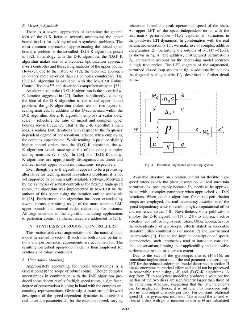
inbetween 0 and the peak operational speed of the shaft.An upper LFT of the speed-independent terms with thereal matrix perturbation −ΩuG captures all variations inthe pointwise LTI dynamics. In combination with the realparametric uncertainty Ωu, we make use of complex additiveuncertainties ∆a perturbing the outputs of Fu (P,−ΩuG),as shown in fig. 4. The additive, unstructured perturbations∆a are used to account for the decreasing model accuracyat high frequencies. The LFT diagram of the augmented,perturbed closed-loop system in fig. 4 additionally includesthe diagonal scaling matrix Wz , described in further detailbelow.
Fig. 4. Perturbed, augmented closed-loop system
Available literature on vibration control for flexible high-speed rotors avoids the plant description via real uncertainperturbations, presumably because Ωu needs to be approxi-mated with a complex parameter when approached via D-Kiterations. When suitable algorithms for mixed perturbationsetups are employed, the real uncertainty description of thespeed-dependency tends to result in high computational effortand numerical issues [18]. Nevertheless, some publicationsemploy the D-K algorithm ([17], [24]) to approach activevibration control for high-speed rotors. Other approaches forthe consideration of gyroscopic effects stated in accessibleliterature utilize combinations of modal [2] and unstructureduncertainties [3]. Due to the implicit description of speed-dependencies, such approaches tend to introduce consider-able conservatism, limiting their applicability and achievableperformance results to a certain extent.
Due to the size of the gyroscopic matrix (16×16), animmediate implementation of the real parametric uncertainty-LFT for the reduced order plant model described in section IIcauses enormous numerical effort and could not be processedin reasonable time using µ-K and (D,G)-K algorithms. Astep from FE to analytical modeling produces a solution: theinertias of the two disks are significantly larger than those ofthe remaining structure, suggesting that the latter elementscan be neglected. Hence, it is sufficient to introduce onlytwo in- and output channels per disk. For constant rotationalspeed Ω, the gyroscopic moments MG around the x- and y-axes of a disk with polar moment of inertia Θ are calculated
2347

using the disk’s angular velocities ϕi:[MG,x
MG,y
]= Ω
[0 Θ−Θ 0
] [ϕxϕy
](20)
By this setup, G can be reduced to an order of four,allowing for mixed µ synthesis at reasonable computationaleffort.
B. Performance Measures
Preceding control synthesis, the perturbed plant model isaugmented for improved performance measures regardingunbalance vibrations. As indicated in section II, the plantinputs do not contain the appropriate characteristics of theactual unbalance excitations, but local force inputs at thedisks. As unbalances do not excite backward whirl modes,efficient performance measures should not highlight gainscorresponding to such modes. Otherwise, significant conser-vatism might be induced, limiting the achievable reductionof forward whirl vibrations.
Intuitively, one might attempt defining closed-loop vibra-tion bounds penalizing high gains at forward whirl frequen-cies heavier than such in the proximity of backward whirlfrequencies. For actual rotor systems, however, the utilizationof such setups is not straightforward as both forward andbackward whirl modes start at the same natural frequencyat standstill. That is, a bound being loose at backwardwhirl frequencies and tight at forward whirl frequencieswould require a large order, subsequently raising the orderof the augmented plant. This might, in turn, increase bothlikelihood of numerical problems and computational effort,respectively. Furthermore, backward whirl frequencies inter-sect with forward whirls of other modes at certain rotationalspeeds. Therefore, we propose an adaptation of the modelinstead of the performance measures. Based on the disk’svibration outputs, additional outputs are generated via modalscaling. For that purpose, the nominal plant model is trans-formed into modal form, providing access to the respectiveinfluences of individual modes on the plant outputs. In modalstate-space representations, the i-th column of the outputmatrix C accounts the impact of the i-th modal state on theoutput vector:
˙x = Ax+ Bu y = Cx (21)
Utilizing a modal state-space representation (21), the un-desired backward whirl modes can be eliminated for per-formance assessment by simply replacing the correspondingelements of C with zeros. To avoid excitation of backwardwhirls by the controller, though, a scaling factor α << 1is imposed instead. Even though the transformation to (21)depends on the rotational speed Ω and some decoupling ofthe modal states x is lost due to the LFT between speed-dependent and -independent terms (see fig. 4), this semi-modal performance approach works very well for the systemat hand. Performance assessment after modal elimination ofbackward whirl influence from the output vector matches therequirement of reducing unbalance excitation at significantlyless conservatism than the use of true displacements.
Ultimately, the augmented plant model displayed in fig.4 enables two choices of performance measures z, physicaldisplacement signals and such after elimination of backwardwhirl influence, respectively. In either case, closed-loop
bounds in the sense of H∞-norm performance assessmentare imposed using a diagonal scaling matrix Wz such thatz∗ = Wzz. The particular choice of closed-loop boundsrestricts the chosen displacements signals in the proximityof the first forward whirl mode at disk one and the sec-ond one at disk two, respectively. This spatial performanceassessment allows penalizing the two forward whirl modeswithin operating range almost independently, as the firstforward whirl mode has more influence on disk one and thesecond on disk two. Notice that without modal elimination ofbackward whirl modes, each of the two closed-loop signalbounds also penalizes the corresponding backward whirls.It is shown in table I and section V how the conservatisminduced by penalizing backward whirl modes notably limitsthe achievable closed-loop performance. Transfer functionsfor random, bounded perturbations including the closed-loopsignal bounds (dashed) are displayed for the initial systembehavior in fig. 5 and after modal backward whirl elimination(BWE) in fig. 6.
101
102
10-4
10-2
100
From: F-d1-x (N) To: q-d1-x (mm)M
ag
nitu
de
(a
bs)
Frequency (Hz)
101
102
10-4
10-2
100
From: F-d2-x (N) To: q-d2-x (mm)
Ma
gn
itu
de
(a
bs)
Frequency (Hz)
Fig. 5. Synthesis setup: perturbed system without backward whirl elimi-nation (solid), closed-loop bound (dashed)
C. Robust Control
The reduction in conservatism achieved when treating Ωuas a real parametric uncertainty is indicated by the µ upperbound peaks of the augmented plant model. These µ peaksare included in table I, the index p referring to robust per-formance, while the superscripts c and m distinguish purelycomplex and mixed perturbation models, respectively. The ra-tios between µc
p and µmp for the particular augmented open-
and closed-loop systems indicate the significant conservatism
2348

101
102
10-4
10-2
100
From: F-d1-x (N) To: q-d1-x-elm (mm)M
ag
nitu
de
(a
bs)
Frequency (Hz)
101
102
10-4
10-2
100
From: F-d2-x (N) To: q-d2-x-elm (mm)
Ma
gn
itu
de
(a
bs)
Frequency (Hz)
Fig. 6. Synthesis setup: perturbed system after backward whirl elimination(solid), closed-loop bound (dashed)
associated with approximating bounded, varying rotationalspeeds by a complex perturbation elements. Furthermore,the final column of table I (i.e., µm
p ) strongly reflects theconservatism induced when utilizing the performance setupwithout backward whirl elimination (BWE, recall fig. 5) fromthe displacement outputs. That is, for each pair of values forµm
p , the one without BWE is notably higher.
TABLE ISSV BOUND PEAK VALUES
Type BWE Order µcp µm
p
Aug. Plant y - 53.21 13.03n - 62.20 14.56
H∞ y 68 40.82 8.73n 68 40.81 9.87
D-K y 68 40.82 8.73n 116 40.77 11.78
IR µ-K y 77 13.87 1.08n 48 12.73 1.51
The µ peaks of the H∞ controllers indicate how unstruc-tured perturbations approximating (4)-(7) are not appropriateto address the perturbations of the system at hand. In fact, thetwo H∞ controllers merely improve the robust performanceof the augmented plant model. Similar results have beenobtained using the D-K algorithm, approximating (4)-(7) bya purely complex perturbation structure and inherently opti-mizing µc
p ≥ µmp . As the D-K iteration implicitly attempts
stabilizing the dynamics subject to complex perturbations,
it does not produce a controller better than the H∞ con-troller used to initialize the algorithm. In fact, the improvedvalue µc
p for the performance setup without backward whirlelimination (BWE) goes in hand with a raise in µm
p and,conclusively, an actual decrease in robust performance.
As expected, the real parametric uncertainty descriptionof the plant’s speed-dependency in combination with appro-priate algorithms allows for significantly better results. Inparticular, the augmented µ-K algorithm including internalorder reduction (IR) of the controllers at each iteration incombination with the utilization of LMI bounds achievedsuperb results. Notice that table I does not include µ peaksfor (D,G)-K controllers due to numerical issues similar tothose reported in the literature [18]. Anyhow, the resultsachieved using the augmented µ-K algorithm for explicittreatment of mixed perturbations and the inclusion of semi-modal performance measures are highly promising.
V. CLOSED-LOOP RESULTS
In order to display the perceptible performance for thetest rig, unbalance simulations are performed. Fig. 7 showssimulated steady-state unbalance vibration amplitudes atdisks 1 and 2 in x-direction, caused by a quasi-stationaryrunup. Due to the almost symmetric closed-loop behavior,y-directions have been omitted. Within all simulations, themaximum voltages are slightly above 300V, which is clearlybelow the maximum amplifier voltage at 500 V, so that nofurther bounding of the control input signals was necessary.The simulated unbalances are those identified for the test rig,publications regarding alternative control schemes applied tothe same test rig indicating that such simulations are suitablefor capturing the actual system behavior [22], [23].
0 2000 4000 6000 80000
0.1
0.2
0.3
q-d
1-x
(m
m)
Ω (rpm)
0 2000 4000 6000 80000
0.1
0.2
0.3
q-d
2-x
(m
m)
Ω (rpm)
Fig. 7. Quasi-stationary runup simulation for unbalance excitation: open-loop plant (solid), closed-loop using IR µ-K controller without BWE(dotted), closed-loop using IR µ-K controller including BWE (dashed)
Corresponding to the achieved peak µ values, the internalreduction (IR) µ-K controllers yield significant vibrationreduction. Comparing both IR µ-K controllers, the onedesigned at the hand of the BWE system achieves remarkably
2349
more reduction than the one designed using physical perfor-mance outputs. The D-K and H∞ controllers do not reducethe resonance amplitudes of the passive system. Althoughtable I shows decreased µ peaks for the corresponding con-trollers. This indicates that, even though the open-loop plantis robustly stable, the complex stability problem dominatesthe complex performance problem. Once more, these resultsdemonstrate how complex uncertainty sets are particularlymore conservative than mixed perturbation setups wheneversevere levels of gyroscopic effects are present.
VI. CONCLUSIONS
We have proposed an efficient framework of synthesizingrobust controllers for flexible high-speed rotors subject tosevere gyroscopic effects via mixed µ synthesis. Employingreal parametric uncertainties, the speed-dependency of thesystem dynamics is appropriately accounted for, whereasthe degree of model-induced conservatism is notably low.In combination with semi-modal performance measures, al-lowing penalties on individual modes, remarkable closed-loop results were shown. In particular, the extended µ-Kalgorithm, incorporating internal order reductions and LMIµ bounds, achieved great attenuation of bending vibrations.Future research directions include extensions regarding timedelays, noise sensitivity, control order reduction, and thesubsequent test rig implementation.
REFERENCES
[1] G.J. Balas, R. Chiang, A. Packard, and M. Safonov, Robust ControlToolbox: Getting Started Guide, The MathWorks, Inc., R2012a edition,2012.
[2] G.J. Balas and P.M. Young, Control Design for Variations in StructuralNatural Frequencies, Journal of Guidance, Control, and Dynamics,Vol. 18, No. 2, Pp. 325-332, 1995.
[3] H.M.N.K. Balini, C.W. Scherer, and J. Witte, Performance Enhance-ment for AMB Systems Using Unstable H∞ Controllers, IEEETransactions on Control Systems Technology, Vol. 19, No. 6, Pp. 1-15,2011.
[4] R.P. Braatz, P.M. Young, J.C. Doyle, and M. Morari, ComputationalComplexity of µ Calculation, Automatic Control, IEEE Transactionson, Vol. 39, No. 5, Pp. 1000-1002, 1994.
[5] C.R. Burrows, M.N. Sahinkaya, and O.S. Turkay, An AdaptiveSqueeze-Film Bearing, ASME Journal of Tribology, Vol. 106, Pp. 145-151, 1984.
[6] Y. Chen and C. Zhu, Active Vibration Control Based on Linear MatrixInequality for Rotor System under Seismic Excitation, Journal ofSound and Vibration, Vol. 314, No. 1-2, Pp. 53-69, 2008.
[7] J.C. Doyle, Analysis of Feedback Systems with Structured Uncertain-ties, Control Theory and Applications, IEE Proceedings D, Vol. 129,No. 6, Pp. 242-250, 1982
[8] J.C. Doyle, Synthesis of Robust Controllers and Filters, In Decisionand Control, The 22nd IEEE Conference on, 1983, Vol. 22, Pp. 109-14, 1983.
[9] J.C. Doyle, A.K. Packard, and K. Zhou, Review of LFTs, LMIs, andµ, In Decision and Control, Proceedings of the 30th IEEE Conferenceon, Vol.2, Pp. 1227-1232, 1991.
[10] M.K.H. Fan, A.L. Tits, and J.C. Doyle, Robustness in the Presence ofMixed Parametric Uncertainty and Unmodeled Dynamics, AutomaticControl, IEEE Transactions on, Vol. 36, No. 1, Pp. 25-38, 1991.
[11] R.L. Fittro and C.R. Knospe, Rotor Compliance Minimization Via µ-Control of Active Magnetic Bearings, IEEE Transactions on ControlSystems Technology, Vol. 10, No. 2, Pp. 238-249, 2002.
[12] R. Gasch, R. Nordmann, and H. Pfuetzner, Rotordynamik, SpringerVerlag, Berlin, Germany, 2006.
[13] H. Gibson, H∞ Control of Active Magnetic Bearings: An IntelligentUncertainty Modeling Approach, PhD Thesis, North Carolina StateUniversity, Raleigh (NC), USA, 2004.
[14] T. Ikeda, Fundamentals of Piezoelectricity, Oxford University Press,USA, 1997
[15] M.E. Johnson, L.P. Nascimento, M. Kasarda, and C.R. Fuller, TheEffect of Actuator and Sensor Placement on the Active Control ofRotor Unbalance, Journal of Vibration and Acoustics, Vol. 125, Pp.365-373, 2003.
[16] S. Kern, Increasing Process Stability of Milling Spindles by ActiveDamping by means of Electromagnetic Actuators, PhD Thesis (inGerman), TU Darmstadt, Darmstadt, Germany, 2008.
[17] A. Lanzon and P. Tsiotras, A Combined Application of H∞ LoopShaping and µ-Synthesis to Control High-Speed Flywheels, IEEETransactions on Control Systems Technology, Vol. 13, No. 5, Pp. 766-777, 2005.
[18] G. Li, Z. Lin, P.E. Allaire, et al., Stabilization of a High Speed Rotorwith Active Magnetic Bearings by a Piecewise µ-Synthesis Controller,6th Symposium on Magnetic Suspension Technology, Turin, Italy,2001.
[19] A.K. Packard, M.K.H. Fan and J.C. Doyle, A Power Method for theStructured Singular Value, Proc. of the 1988 IEEE Conference onControl and Decision, Pp. 2132-2137, 1988.
[20] A.B. Palazzolo, R.R. Lin, R.M. Alexander, A.F. Kascak, and J. Mon-tague, Test and Theory for Piezoelectric Actuator-Active VibrationControl of Rotating Machinery, Journal of Vibration, Acoustics, Stress,and Reliability in Design, Vol. 113, No. 2, Pp. 167-175, 1991.
[21] B. Riemann, E.A. Perini, K. Lucchesi-Cavalca, H. Fiori de Castro,and S. Rinderknecht, Oil Whip Instability Control Using µ-SynthesisTechnique on a Magnetic Actuator, Journal of Sound and Vibration,Vol. 332, No. 4, Pp. 654-673, 2013.
[22] Z. Wang, R.S. Schittenhelm, M. Borsdorf, and S. Rinderknecht,Application of Augmented Observer for Fault Diagnosis in RotorSystems, Engineering Letters, Vol. 21, No. 1, Pp. 10-17, 2013
[23] R.S. Schittenhelm, B. Riemann, and S. Rinderknecht, Active VibrationControl for a Rotor System Subject to Gyroscopic Effects using theFxLMS-Algorithm (in German), Vibrations in Rotating Machines,Berlin, 2013.
[24] U. Schoenhoff, Practical Robust Control of Mechatronic Systemswith Structural Flexibilities, PhD Thesis, TU Darmstadt, Darmstadt,Germany, 2003.
[25] M. Sehr, Synthesis of Robust Controllers for Mixed Uncertaintiesvia µ-K Iteration, M.Sc. thesis, Dept. Mechanical Engineering, TUDarmstadt, Germany, 2012.
[26] M.S. Senousy, R.K.N.D. Rajapakse, and M.S. Gadala, Self-HeatGeneration in Piezoelectric Stack Actuators used in Fuel Injectors,Smart Materials and Structures, Vol. 18, No. 4, 2009.
[27] S. Toeffner-Clausen, P. Andersen, J. Stoustrup, and H.H. Niemann,A New Approach to µ-Synthesis for Mixed Perturbation Sets, InProceedings of the 3rd European Control Conference, ECC95, Pp.147-152, 1995.
[28] S. Toeffner-Clausen, System Identification and Robust Control: A CaseStudy Approach, Springer London, 1996.
[29] K. Youcef-Toumi and S. Reddy, Dynamic Analysis and Control ofHigh Speed and High Precision Active Magnetic Bearings, Journalof Dynamic Systems, Measurement and Control, Transactions of theASME, Vol. 114, No. 4, Pp. 623-633, 1992.
[30] P.M. Young and J.C. Doyle, Computation of µ with Real and ComplexUncertainties, Proceedings of the 29th IEEE Conference on Decisionand Control, Pp. 1230-1235, 1990.
[31] P.M. Young, M.P. Newlin, and J.C. Doyle, Practical Computationof the Mixed µ Problem, Proceedings of the American ControlConference, Pp. 2190-2194, 1992.
[32] P.M. Young, Controller Design with Mixed Uncertainties, In AmericanControl Conference, Vol. 2, Pp. 2333-2337, 1994.
[33] P.M. Young, Controller Design with Real Parametric Uncertainty,International Journal of Control, Vol. 65, No. 3, Pp. 469-509, 1996.
[34] P.M. Young, Structured Singular Value Approach for Systems withParametric Uncertainty, International Journal of Robust and NonlinearControl, Vol. 11 No. 7, Pp. 653-680, 2001.
[35] K. Zhou, J.C. Doyle, and K. Glover, Robust and Optimal Control,Prentice Hall, 1996.
[36] K. Zhou, Frequency-Weighted Model Reduction with L∞ ErrorBounds, Systems & Control Letters, Vol. 21, 115-125, 1993.
2350