robust digital image watermarking algorithms for copyright ... · 4.3.1 fourier transform 64 4.3.2...
TRANSCRIPT

Robust digital image watermarking algorithms for copyright protection
Von der Fakultät für Ingenieurwissenschaften
der Universität Duisburg-Essen
zur Erlangung des akademischen Grades einer
Doktorin der Ingenieurwissenschaften
genehmigte Disertation
von
Nataša Terzija
aus Belgrad
Referent: Prof. Dr. Walter Geisselhardt
Korreferent: Prof. Dr. Josef Pauli
Tag der mündlichen Prüfung: 18.10.2006

Acknowledgement:
I would like to express my thanks to Prof. Walter Geisselhardt, who supervised my
academic activities at the University Duisburg-Essen and gave me freedom and optimal
conditions necessary for my research. I especially thank Prof. Josef Pauli, who read the
manuscript and provided corrections and useful comments.
Thanks are also due to Prof. Hans-Dieter Kochs, who has also supported my
research, and to all those outstanding individuals with whom I have worked in the past, who
helped me understanding watermarking and its applications better, including Prof. Gerlind
Plonka-Hoch and Prof. Zoran Bojkovic (Univ. of Belgrade, Serbia).
I would also like to thank my whole family for encouragement and love. Without it,
my thesis could never have been completed.

Keywords
Digital image watermarking, Scale invariant feature point detectors, Image registration,
Synchronization technique for watermark detection, Discrete Wavelet Transform, Complex
Wavelet Transform, Error Correction Codes.

ABSTRACT
Digital watermarking has been proposed as a solution to the problem of resolving
copyright ownership of multimedia data (image, audio, video). The work presented in this
thesis is concerned with the design of robust digital image watermarking algorithms for
copyright protection.
Firstly, an overview of the watermarking system, applications of watermarks as well
as the survey of current watermarking algorithms and attacks, are given. Further, the
implementation of feature point detectors in the field of watermarking is introduced. A new
class of scale invariant feature point detectors is investigated and it is shown that they have
excellent performances required for watermarking.
The robustness of the watermark on geometrical distortions is very important issue
in watermarking. In order to detect the parameters of undergone affine transformation, we
propose an image registration technique which is based on use of the scale invariant feature
point detector. Another proposed technique for watermark synchronization is also based on
use of scale invariant feature point detector. This technique does not use the original image
to determine the parameters of affine transformation which include rotation and scaling. It is
experimentally confirmed that this technique gives excellent results under tested
geometrical distortions.
In the thesis, two different watermarking algorithms are proposed in the wavelet
domain. The first algorithm belongs to the class of additive watermarking algorithms which
requires the presence of original image for watermark detection. Using this algorithm the
influence of different error correction codes on the watermark robustness is investigated.
The second algorithm does not require the original image for watermark detection. The
robustness of this algorithm is tested on various filtering and compression attacks. This
algorithm is successfully combined with the aforementioned synchronization technique in
order to achieve the robustness on geometrical attacks.
The latter watermarking algorithm presented in the thesis is developed in complex
wavelet domain. The complex wavelet transform is described and its advantages over the
conventional discrete wavelet transform are highlighted. The robustness of the proposed
algorithm was tested on different class of attacks. Finally, in the thesis the conclusion is
given and the main future research directions are suggested.

i
Content:
1. Introduction 1 1.1 Importance of Digital Watermarking and Watermarking Applications 1
1.2 Motivation 3
1.3 Thesis contribution 5
1.4 Thesis organization 6
2. Introduction to Watermarking Technology 8 2.1 Types of digital watermarks 8
2.2 Watermark requirements for still images 11
2.3 Structure of a typical watermarking system 12
2.3.1 Embedding process 12
2.3.2 Extraction/detection process 13
2.4 Watermarking as a communication problem 14
2.5 Properties of the watermark 17
2.6 Watermarking Algorithms 25
2.7 Benchmarking and performance evaluation of watermarking schemes 26
2.8 Watermarking for copyright protection 27
2.9 Chapter Summary 30
3. Watermarking Techniques Based on the use of Feature Point
Detectors 31 3.1 Introduction 31
3.2 Difference of Gaussian feature point detector 35
3.3 Comparison of the feature point detectors 41
3.4 Chapter Summary 49

ii
4. The synchronization issue in watermarking schemes 50 4.1 Image registration techniques 51
4.2 Watermarking techniques dealing with the problem of desynchronisation
without access to the original image content 57
4.2.1 Exhaustive search 57
4.2.2 Periodical sequences 57
4.2.3 Invariant domains 58
4.2.4 Synchronization marks (pilot signals, template) 59
4.2.5 Content based approaches 63
4.3 Proposed synchronization technique 63
4.3.1 Fourier transform 64
4.3.2 Description of the proposed synchronization technique 69
4.3.2.1 Template embedding algorithm 72
4.3.2.1 Template extraction algorithm 73
4.3.3 Discussion about the relevant parameters of the proposed technique 76
4.3.4 Testing results 82
4.3.5 Comparison with other techniques and the advantages of the proposed
technique 83
4.4 Chapter Summary 84
5. Digital image watermarking in wavelet domain 85 5.1 Discrete wavelet transform 85
5.2 Properties of the wavelet transform 89
5.3 HVS Perceptual models based on DWT 90
5.4 Algorithms Classification 91
5.5 The non-blind additive watermarking algorithm (NB-T01) 92
5.5.1 The watermark embedding procedure 92
5.5.2 Watermark extraction procedure 94
5.5.3 Algorithm NB-T01 testing 94
5.5.4 Impact of different Reed-Solomon codes 98
5.5.5 Improvement of the algorithm 98
5.6 Proposed blind watermarking algorithm (B-T02) 98

iii
5.6.1 Embedding procedure 99
5.6.2 Detection procedure 101
5.6.3 Algorithm B-T02 Testing 103
5.6.4 Robustness on geometrical attacks 112
5.7 Chapter Summary 113
6. Digital image watermarking in complex wavelet domain 114 6.1 Introduction 114
6.2 Complex wavelet transform and its properties 115
6.3 Watermarking algorithms 119
6.4 The new watermarking algorithm based on DT - CWT (C - T03) 121
6.4.1 Embedding procedure 121
6.4.2 Detection procedure 125
6.4.3 Testing results (C-T03) 126
6.4.4 Robustness on geometrical attacks 130
6.5 Chapter Summary 132
7. Conclusion and Future Research Directions 133 7.1 Thesis Review 133
7.2 Future Research Directions 136
Appendices 138
Appendix A Comparison of Feature Points Detectors: Results 139
Appendix B Radon Transform 142
Appendix C Fourier-Mellin Transform 143
Appendix D Shift Invariance by Parallel Filter Banks 144
Appendix E Test Images 148
List of Publications 149
References 150

iv
ACRONYMS
ACF autocorrelation function
AWGN additive Gaussian white noise
bpp bit per pixel
BCH Bose-Chaudhuri-Hocquenghem error correction code
CWT Complex Wavelet Transform
DCT Discrete Cosine Transform
DFT Discrete Fourier Transform
DT-CWT Dual-Tree Complex Wavelet Transform
DWT Discrete Wavelet Transform
ECC Error Correction Code
FMT Fourier-Mellin Transform
HVS Human Visual System
ICWT Inverse CWT
IDWT Inverse DWT
JND just noticeable difference
JPEG Joint Photographic Expert Group
LoG Laplacian of Gaussian
LPM Log Polar mapping
LSB Least Significant Bit
MSE Mean Square Error
PR Perfect Reconstruction
PSNR Peak Signal to Noise Ratio
RS Read-Solomon error correction code
QIM Quantisation Index Modulation
SIFT Scale Invariant Feature Transform
SS Spread Spectrum

v
List of Figures
1.1 Thesis organization. 7
2.1 Types of watermarking techniques. 9
2.2 Embedding unit, as a part of a watermarking system. 13
2.3 The extraction/detection process. 14
2.4 Standard model of communication system. 15
2.5 Random geometric distortion model. 23
3.1 Feature points of the Lena image extracted with the Harris corner detector. 33
3.2 Feature point on Lena image detected with Harris-Affine detector. 34
3.3 Feature point on Lena image detected with SIFT detector. 34
3.4 The pyramid of difference of Gaussian. 38
3.5 Detecting of maximum and minimum of SIFT images. 38
3.6 Computation of keypoint descriptors. 40
3.7 Feature points extracted on Lena image with SIFT and Harris-Affine detector. 45
3.8 The average number of the corresponding points after non-geometrical
distortions. 47
3.9 The average number of the corresponding after rotation and image scaling
distortions. 48
3.10 The average number of the corresponding after image cropping and
combination of rotation and image scaling distortions. 48
4.1 (a) Original Lena image. (b) Lena image after G1 attack. The corresponding
feature points are presented on the both images. (c) Reconstructed image. 54
4.2 (a) Original Lena image. (b) Lena image after G2 attack. The corresponding
feature points are presented on the both images. (c) Reconstructed image. 54
4.3 (a) Original Lena image. (b) Lena image after G3 attack. The corresponding

vi
feature points are presented on the both images (c) Reconstructed image. 55
4.4 (a) Original Lena image. (b) Lena image after G4 attack. The corresponding
feature points are presented on the both images. (c) Reconstructed image. 55
4.5 (a) Original Lena image. (b) Lena image after G5 attack. The corresponding
feature points are presented on the both images (c) Reconstructed image. 55
4.6 (a) Original Lena image. (b) Lena image after G6 attack. The corresponding
feature points are presented on the both images (c) Reconstructed image. 56
4.7 Rotation, scale, translation invariant Fourier Mellin domain. 59
4.8 The examples of different templates used in the DFT domain. 59
4.9 Radon Transform of: (a) Lena image; (b) rotated Lena image for 30 . 61
4.10 Log-polar mapping, inverse log-polar mapping and difference image. 69
4.11 Embedding of two template point structures in DFT domain. 71
4.12 One example of embedded template points in log-polar coordinates of
Fourier spectra. 73
4..13 The circular regions selected for template embedding. 76
4.14 The peaks of cross-correlation function. 78
4.15 . Log-polar representation of the region with and without template points 79
4.16 Template peaks extracted after geometrical distortion and corresponding
cross correlation peaks. 80
4.17 Lena image with embedded template points; difference image and circle
regions around the feature points containing the template. 82
5.1 One level of decomposition of two-dimensional DWT. 87
5.2 The pyramidal structure. 88
5.3 Two-level DWT decomposition of Lena image obtained by using the Haar
wavelet filter. 88
5.4 Block diagram of the embedding method. 93
5.5 The testing results for different filtering attacks, JPEG2000 and JPEG
compression attacks. 97
5.6 The results of our watermarking algorithm for different attacks: 109
5.7 Watermarked Barbara image and difference image. 111
6.1 Analysis and synthesis filter banks for the dual-tree discrete CWT. 117

vii
6.2 2-D filter impulse responses of DT-CWT. 118
6.3 Example of the CWT decomposition of House image. 118
6.4 Block scheme of the embedding procedure 123
6.5 Watermarked image wI after attacks. 123
6.6 Block scheme of the extraction procedure. 125
6.7 The original and watermarked Lena image. 128
6.8 Decompositions of Lena image into the spatial representations. 129
D.1 DWT filter bank. 144
D.2 One level of complex dual tree filter bank. 146
E Test images 148

viii
List of Tables
3.1 The properties of the feature point detectors. 34
4.1 The affine computation. 56
4.2 The calculated PSNR values. 83
5.1 The characteristic of the embedded watermark. 95
5.2 The results. 111
6.1 Table of constants used in CWT visual model. 127
6.2 PSNR values (dB) of the analyzed images. 127
6.3 The results for non-geometrical attacks. 131
6.4 Comparison of the existing watermarking methods based on DT-CWT. 132
A.1 The number of corresponding feature points between the distorted image
and original test image. 139
A.2 The number of corresponding feature points between the distorted image
and original test image. 140
A.3 The number of corresponding feature points between the distorted image
and original test image. 141

Introduction
1
Chapter 1
Introduction
With the widespread distribution of digital information over the World Wide Web
(WWW), the protection of intellectual property rights has become increasingly important.
These information, which include still images, video, audio, or text are stored and
transmitted in a digital format. Information stored in digital format can be easily copied
without loss of quality and efficiently distributed. Because of easy reproduction,
retransmission and even manipulation, it allows a pirate (a person or organization) to violate
the copyright of real owner. The design of techniques for preserving the ownership of digital
information is in the basic of the development of future multimedia services.
1.1 Importance of Digital Watermarking and Watermarking
Applications
There are few approaches designed for protecting data and securing systems. One of
them is data encryption (cryptography). Based on conventional cryptographic system, parts
of the data may be protected from an unauthorized person by applying any of existing
cryptographic algorithms [1]. Only a person who possesses appropriate key (or keys) can
decrypt the encrypted data. The drawback of this data protection strategy is that once such a
data is decrypted by a pirate, there is no way to protect the data and track the illegal
distribution. Also it is impossible legally to prove the ownership. The next approach to
protect the intellectual property rights is watermarking. Watermarking is a technique for
embedding hidden data that attaches copyright protection information to digital information.
This provides an indication of ownership of the digital data.
Introduction
2
Watermarking is closely related to steganography in that they are both concerned
with covert communication and belong to a broader subject known as information hiding.
Steganography, derived from Greek, literally means “covered writing” is the art of hiding
information inside other data in ways that prevent the detection of hidden message. A
steganographic system is typically not required to be robust against intentional removal of
the hidden message. On the other hand, the watermarking requires that the hidden message
should be robust to attempts aimed at removing it. In the case of copyright protection the
copyright information should resist any modifications by pirates intending to remove it. This
is a significant step forward compared to a common steganography.
Watermarking is either “visible” or “invisible”. Perceptible mark (“visible
watermark”) of ownership or authenticity has been around for centuries in the form of
stamps, seals, signatures or classical watermarks. Nevertheless, for known data
manipulation technologies the imperceptible digital watermarks are mandatory in most of
applications. The up to date known watermarking applications considered in the open
literature are as follows [2]:
• Copyright Protection: for the protection of the intellectual property, the data
owner can embed a watermark representing copyright information in the data.
The embedded watermark can be used as a proof, e.g. in a court if someone
intentionally infringed the copyrights.
• Fingerprinting: to trace the source of illegal copies, the owner can use the
fingerprinting technique. In this case, the owner can embed different watermarks
in the copies of the data that are supplied to different customers. Fingerprinting
can be compared to embedding a serial number that is related to the customer’s
identity in the data. It enables the intellectual property owner to identify
customers who have broken their license agreement by supplying the data to
third parties.
• Copy protection: the information stored in watermark can directly control digital
recording devices for copy protection purposes. In this case the watermark
represents a copy-prohibit bit and watermark detectors in the recorder determine
whether the data offered to the recorder may be stored or not.

Introduction
3
• Broadcast monitoring: by embedding a watermark in commercial
advertisements, an automated monitoring system can verify whether the
advertisements are broadcasted as contracted. Broadcast monitoring can protect
not only the commercials but also the valuable TV products.
• Data authentication: the so called fragile watermarks can be used to check the
authenticity of data. A fragile watermark indicates whether the data has been
altered. Further it offers the information in which part the data are being altered.
• Indexing: indexing of video mail, where comments can be embedded in the
video content; indexing of movies and news items, where markers and comments
can be inserted in order to be used by search engines.
• Medical safety: embedding the date and the patient’s name in medical images
could be a useful safety measure.
• Data Hiding: watermark techniques can be used for the transmission of secret
messages. Since various governments restrict the use of encryption services,
people can hide their messages in other data.
1.2 Motivation
Digital media (image, video, audio, etc.) are now widely distributed on the Internet.
Because of easy reproduction and manipulation of digital media, the protection of
intellectual property rights has become an important issue. Digital watermarking is expected
to be a perfect tool for protecting the intellectual property rights.
The main advantages of the watermarks over other techniques are:
- They are imperceptible.
- They are not removed when the data are converted to other file formats.
- They undergo the same transformations as the data in which they are embedded.
The ideal properties of a digital watermark include the imperceptibility and robustness.
The watermarked data should retain the quality of the original one as closely as possible.

Introduction
4
Robustness refers to the ability to detect the watermark after various types of intentional or
unintentional alterations (so called attacks). Various watermarking schemes have been
proposed in the present. Unfortunately, up to now there is no algorithm that perfectly fulfils
the aforementioned fundamental watermarking requirements: the imperceptibility to the
human visual perception and the robustness to any kind of watermarking attacks.
Particularly this fact was a challenge to investigate the opportunities of designing
watermarking techniques being capable to achieve the imperceptibility and robustness
criteria.
Part of the watermarking research is focused on the watermark embedding process. A
watermark can be embedded in a spatial domain [3-8], Discrete Fourier Transform (DFT)
domain [9-11], Discrete Cosine Transform (DCT) domain [12-16], Discrete Wavelet
Transform domain (DWT) [17-21], Complex Wavelet Transform [22, 23] etc.
Watermarking algorithms performed in the spatial domain show very good results regarding
the watermark imperceptivity and capacity. At the same time they show the lack of
robustness on compression and general signal processing attacks. On the other hand, the
algorithms in the transform domain showed excellent robustness properties. Various image
transforms have been considered, among them the DCT, used in the JPEG [24] coding
standard, and the DWT, which becomes more and more attractive with its use in the
JPEG2000 [25] coding standard. The CWT has not been widely used in the field of
watermarking. Only few algorithms using the CWT have been introduced in the past. Te
CWT [26] was developed as an extension of the commonly known DWT. Although the
CWT has several important improvements with regard to the DWT (approximately shift
invariance and improved directional selectivity), there is still a need to study deeply the
watermark embedding techniques in the CWT domain.
The robustness of the watermark on geometrical attacks is the next open problem in
the field of watermarking. Even the minor geometrical manipulation to the watermarked
image can dramatically reduce the ability of the watermark detector to detect the watermark.
Commonly used approaches to protect the watermark against geometrical distortions are
based on invariant transformations [27-29], embedding synchronization marks [30-34],
robust image content characteristics [35-37], etc. The image content-based methods also
referred to as a second generation watermarking schemes [35], use significant data features
in watermarking process (here the data is referred to be an image). One example of
significant data features are feature points, which can be used as the reference locations for

Introduction
5
the both the watermark embedding and detection process. Here the feature point detectors
are used to extract the feature points.
In the open literature a wide variety of feature point detectors can be found. Among
them the Harris corner detector [38] and the Mexican scale interaction method [39] are
widely used in designing the watermarking schemes. The group of scale invariant feature
point detectors [40], which are robust on transformations such as rotation, scale, translation,
illumination changes or even projective transformation [41], are promising techniques to be
considered in the field of watermarking.
1.3 Thesis contribution
In this thesis the robust digital image watermarking algorithms for copyright
protection are studied. The objectives of this work were to develop novel image
watermarking algorithms providing a performance enhancement over the other existing
algorithms presented in the open literature and to validate their performance in the presence
of the standard watermarking attacks.
The key points addressed in this research include the following:
1. Performance comparison of a relatively new class of scale-invariant feature points
detectors. The robustness of two different scale-invariant feature point detectors to
the standard image processing operations is tested and compared. The potential
application of this new class of feature point detectors in watermarking field is
outlined.
2. Demonstration of an image registration technique [42, 43], based on establishing
point-by-point correspondence between the original image and image possibly
altered by unknown geometrical transformation (received image). When the
correspondence between two images is determined, the parameters of the undergone
geometrical transformation are estimated and an inverse geometrical transformation
is calculated and applied to the received image. This technique effectively estimates
the parameters of undergone affine transformation.

Introduction
6
3. Development of a new synchronization technique [44], which can be used in a
process of watermark detection. The technique is based on the application of scale-
invariant feature point detectors and it enables the calculation of the affine
transformation parameters. The parameters of affine transformation are limited to
scale and rotation. This technique does not require the original image and can be also
applied if the affine transformed original image is cropped.
4. A classical non-blind additive watermarking algorithm in wavelet domain has been
used to investigate the impact of different error correction codes on the watermark
robustness [45, 46].
5. The proposal of a wavelet based watermarking algorithm, which does not require the
original image for watermark extraction. In order to increase the robustness on
geometrical distortions, the proposed watermarking algorithm can be successfully
combined with the aforementioned synchronization technique.
6. The proposal of a complex wavelet based watermarking algorithm [47], which
improves the existing watermarking algorithms based on the complex wavelet
transform. The complex wavelets have not been widely used in the watermarking,
although they have several desirable features, which can be applied for
watermarking. The proposed algorithm requires the original image for watermark
extraction and it can be combined with the image registration technique for
increasing the robustness on geometrical attacks.
1.4 Thesis organization
In Chapter 2 the introduction to watermarking technology is given. The basic terms in
the field of watermarking are explained. Chapter 3 gives firstly an overview of
watermarking techniques based on use of feature point detectors. Then a new class of scale
invariant feature point detectors is introduced and it will be later implemented for the design
of the watermark synchronization technique. A comparison between two different scale-
invariant feature point detectors is performed in order to show which scale invariant feature
point detector has the best performances for image watermarking. The synchronization issue
in watermarking schemes is considered in Chapter 4. Firstly, an image registration

Introduction
7
technique is described and experimentally tested. Then, an overview of the existing
watermarking techniques, which consider the problem of desynchronisation without access
to the original image content is given. After that a new synchronization technique based on
use of scale invariant feature point detectors is described and tested. The watermarking
algorithms in discrete wavelet domain are considered in Chapter 5. The brief description of
discrete wavelet transform with its properties related to the watermarking is given as well as
the classification and literature survey of the existing watermarking algorithms based on
DWT. After that, the two different watermarking algorithms based on discrete wavelet
transform are proposed and tested. Chapter 6 introduces the watermarking in the complex
wavelet transform. The Complex wavelet transform with its properties is firstly, briefly
described. Then the existing watermarking algorithms based on complex wavelet transform
are overviewed. The new watermarking algorithm based on complex wavelet transform is
proposed and tested. Finally, summary of this thesis and further research directions are
presented in Chapter 7.
The thesis organization is summarized in the Figure 1.1.
Figure 1.1: Thesis organization.

Introduction to watermarking technology
8
Chapter 2
Introduction to Watermarking Technology
This Chapter gives a brief introduction to watermarking technology. Section 2.1
introduces the basic terms of digital watermarking. The watermarking requirements and the
structure of the typical watermarking system are given in Sections 2.2 and 2.3. In Section
2.4 the watermarking problem is formulated as a communication problem. Section 2.5
considers the most important properties of the watermarking system. A literature survey of
the watermarking algorithms is presented in Section 2.6. In Section 2.7 the evaluation
parameters of the watermarking algorithms, as well as the current benchmarking software
are considered. The watermarking protocol for copyright protection is discussed in Section
2.8.
2.1 Types of digital watermarks
Digital watermarking is the process that embeds data called a watermark into a
multimedia object in such a way that the watermark can be later on detected or extracted for
object assertion purposes. The multimedia objects, in which the watermark is embedded, are
usually called: the original, cover signal, host signal or simply the work.
A digital watermark is a distinguishing piece of information that is assigned to the
data to be protected. One important requirement by this is that the watermark cannot be
easily extracted or removed from the watermarked object.
Watermarks and watermarking techniques can be classified into several categories
taking into account by this various criteria (see Figure 2.1 in which the types of watermarks
are presented) [2]. As it can be noted, one of the criteria is embedding domain in which the
Introduction to watermarking technology
9
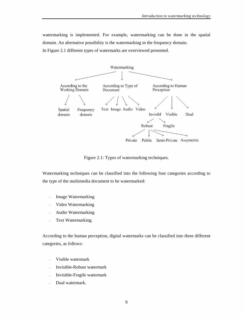
watermarking is implemented. For example, watermarking can be done in the spatial
domain. An alternative possibility is the watermarking in the frequency domain.
In Figure 2.1 different types of watermarks are overviewed presented.
Figure 2.1: Types of watermarking techniques.
Watermarking techniques can be classified into the following four categories according to
the type of the multimedia document to be watermarked:
- Image Watermarking
- Video Watermarking
- Audio Watermarking
- Text Watermarking.
According to the human perception, digital watermarks can be classified into three different
categories, as follows:
- Visible watermark
- Invisible-Robust watermark
- Invisible-Fragile watermark
- Dual watermark.

Introduction to watermarking technology
10
The visible watermark appears visible to a casual viewer on a careful inspection. The
invisible-robust watermark is so embedded that alterations made to the pixel cannot be
perceptually noticed. Also the watermark should withstand the standard signaling operations
(so called “attacks”, see Section 2.5) and it can be recovered with appropriate decoding
mechanism only. The invisible-fragile watermark is embedded in such a way that any
manipulation or modification of the image causes the watermark destruction, or alteration.
The dual watermark is a combination of the visible and the invisible watermarks. In this
type of watermarks an invisible watermark is used as a back up for the visible watermark.
The robust watermarking schemes can be classified in the following categories:
- private watermarking scheme, which requires the original image for watermark
detection. There are two types of private watermarking schemes:
o Type I systems, which extract the watermark from the tested, possibly
distorted image and use the original image to find the location of the
watermark in distorted image.
o Type II systems, which requires an additional copy of the embedded
watermark for watermark detection and they are only able to tell whether a
given watermark is present or not in the tested image.
In both systems knowledge about the private/embedded key is required. Here the
private key is a secret data used to embed the watermark.
- semi-private watermarking, which does not use the original image for detection. It
gives the information if the watermark is present or not.
- public watermarking (also referred to as blind watermarking), which requires neither
the secret original image nor the embedded watermark in watermark extraction
procedure.
- asymmetric watermarking (also referred to as public-key watermarking), in which
the detection process and particularly the detection key are fully known to anyone,
as opposed to blind watermarking approaches where a secret key is required for
detection of watermark. The knowledge of the public key either does not help to
compute the private key, or does not allow the watermark removal.
Introduction to watermarking technology
11
2.2 Watermark requirements for still images
In the open literature various watermarking techniques have been proposed in the
past. In order to be effective, a watermark should have the main features, as outlined below
[2]:
- Fidelity: the embedding algorithm must embed the watermark in such a way that this
does not affect the quality of the host image. If the humans cannot distinguish the
original data from the data with the inserted watermark, the watermark-embedding
procedure is considered to be truly imperceptible. Even the smallest modification in
the host image may become apparent when the original data is compared with
watermarked data. Usually the users of the watermarked data do not have access to
the original data. Thus, the aforementioned comparison cannot be performed. It may
be sufficient that the modifications in the watermarked data stay unnoticed, as long
as the data are not compared with the original image.
- Payload of the Watermark: the amount of information that can be stored in a
watermark.
- Robustness: The watermark must be difficult to be removed from the object. The
watermark should be immune to standard unintentional and intentional
manipulations. It should be robust against various common signal processing
techniques (e.g. compression, quantization, etc.) and common geometric distortions
(e.g. cropping, rotation, etc.). Furthermore, it should be statistically unremovable.
That means that a statistical analysis should not produce any advantage from the
attacking point of view.
- Unambiguousness: the retrieval of the watermark should unambiguously identify the
owner.
Introduction to watermarking technology
12
2.3 Structure of a typical watermarking system
Every watermarking system consists of at least two different units:
- the watermark embedding unit and
- the watermark detection/extraction unit.
Both units can be considered as separate processes, described in the next Subsections.
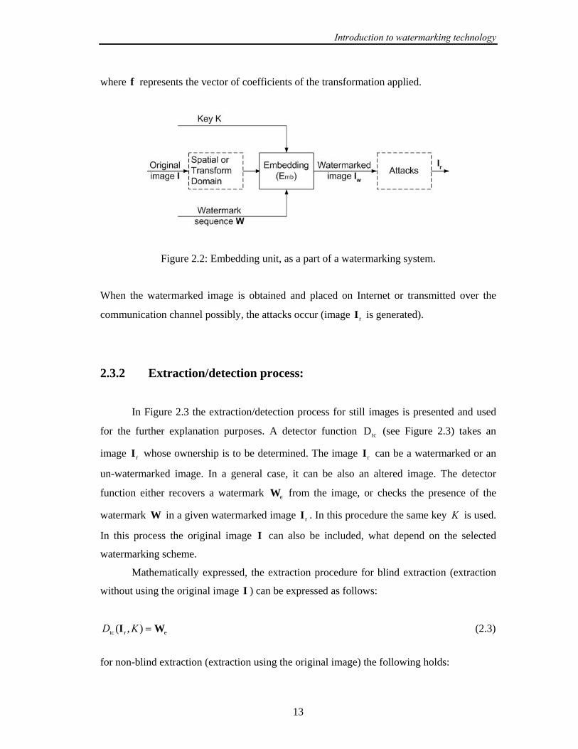
2.3.1 Embedding process:
In Figure 2.2 the embedding process for still images is presented and used for the
explanation purposes. Let us denote an original image by I , a watermark by W , the
watermarked image by WI and K is the embedded key (see Figure 2.2). The embedding
function mbE takes on its input the image I , watermark W and key K and generates a new
watermarked image, denoted with WI . Introduction of the embedded key K is necessary for
enhancing the security aspect of the watermarking system. Before the embedding process,
the original image can be either transformed in the frequency domain or the embedding can
be performed in spatial domain. The domain selection depends on the selected
watermarking technique. If the embedding is performed in frequency domain, the inverse
transform must be applied in order to obtain the watermarked image. Mathematically
expressed, the embedding function for the spatial domain techniques can be represented as
follows:
Wmb K IWI =),,(E (2.1)
for the frequency domain technique, the following expression is valid.
Wmb K IWf =),,(E (2.2)
Introduction to watermarking technology
13
where f represents the vector of coefficients of the transformation applied.
Figure 2.2: Embedding unit, as a part of a watermarking system.
When the watermarked image is obtained and placed on Internet or transmitted over the
communication channel possibly, the attacks occur (image rI is generated).
2.3.2 Extraction/detection process:
In Figure 2.3 the extraction/detection process for still images is presented and used
for the further explanation purposes. A detector function tcD (see Figure 2.3) takes an
image rI whose ownership is to be determined. The image rI can be a watermarked or an
un-watermarked image. In a general case, it can be also an altered image. The detector
function either recovers a watermark eW from the image, or checks the presence of the
watermark W in a given watermarked image rI . In this procedure the same key K is used.
In this process the original image I can also be included, what depend on the selected
watermarking scheme.
Mathematically expressed, the extraction procedure for blind extraction (extraction
without using the original image I ) can be expressed as follows:
ertc ),( WI =KD (2.3)
for non-blind extraction (extraction using the original image) the following holds:

Introduction to watermarking technology
14
ertc ),,( WII =KD (2.4)
The blind watermark detection generates at its output a binary value indicating the
presence or absence of the watermark W . By this, the following can be assumed:
⎩⎨⎧
=presentnotiswatermark,0
presentiswatermark,1),,( rdtc KD WI (2.5)
A watermark must be extractable or detectable. In the watermarking extracting schemes the
watermark is being extracted in its exact, original form. On the other hand, if detecting only
whether a specific given watermarking signal is present in an image, or not, the scheme is
called the watermark detection scheme. Note that the watermark extraction can prove the
ownership, whereas the watermark detection can only verify it.
Figure 2.3: The extraction/detection process.
2.4 Watermarking as a communication problem
The watermarking process is usually described as a communication over distorting
channel [2]. To understand the similarities between watermarking and conventional
communication, we will briefly review the traditional model of communication system.

Introduction to watermarking technology
15
Then some components of a communication system that will be relevant to the extension to
watermarking will be highlighted.
In Figure 2.4 the main elements of the traditional data communications model are
depicted.
Figure 2.4: Standard model of communication system.
Here the main objective is to transmit a message m across a communications channel. In
order to prepare it for transmission over the channel, the channel encoder usually encodes
this message. The channel encoder is a function, mapping each possible message into a code
word, in Figure 2.4 denoted as x , drawn from a set of signal that can be transmitted over the
communications channel. Commonly, the encoder consist of a source coder and a
modulator. The source coder removes the redundancy from the input message and maps a
message into a sequence of symbols drawn from some alphabet. The role of the modulator
is to convert a sequence of symbols from the source coder into a signal suitable for the
transmission through a physical communications channel. By this, different modulation
techniques, such as amplitude, phase, or frequency modulation, can be implemented.
The signal x is subsequently sent over the communications channel, which is
assumed to be noisy. The consequence of the presence of noise is that the received signal,
conventionally denoted as y, is generally different from x . The intensity of this difference
depends of the level of the noise present in the channel. Here it is assumed that the noise is
considered as an additive noise. In other words, the transmission channel is modeled by
adding a random noise n to the encoder’s output x . At the receiver part of the system, the
received signal, y , is forwarded, as the input signal, to the channel decoder which inverts
the encoding process and attempts to correct the errors caused by the presence of noise. This
is a function that maps transmitted signals into messages rm . If the channel code is well
matched to a given channel model, the probability that the decoded message contains an
error is negligibly small.

Introduction to watermarking technology
16
The noise signal n is usually modeled independently of the signal x . The simplest
and most important channel for analysis is a Gaussian channel where each element of the
noise signal is drawn independently from a normal distribution with zero mean and a
variance 2nσ . By this, the variance models the level of distortion of the signal introduced by
the channel noise. The zero mean distribution means that the channel noise does not have an
impact on the DC component of the transmitted signal. This model is the most frequently
used one in the watermark literature.
The fundamental process in each watermarking system can be modeled as a form of
communication in which a message is transmitted from the watermark embedder to the
watermark receiver [2]. In the watermarking-communications model, the process of the
watermarking is seen as a transmission channel through which the watermark message is
being sent, with the host image being a part of this channel. Firstly, the message m , which
has to be transmitted, is encoded typically by the error correction codes to produce the
coded message. This coded message is mapped into a watermark pattern w using a secret
key K . After that, the watermark is added to the host image I , constructing by this the
watermarked image wI . If the watermark embedding process does not use information about
the host image, it is called the blind watermark embedding, otherwise the process is referred
to as an informed watermark embedding. After the added pattern is embedded, it is assumed
that the watermarked image is distorted by watermark attacks. As in the data
communications model, the distortions of the watermarked signal are modeled as additive
noise. The next step in this model is watermark extraction and message decoding.
The original image plays an important role if it is available to the embedder. This
watermarking is referred as a communication problem with side information at the
transmitter [48]. The idea is that instead of treating the cover image as a noise, it could be
treated as side information and used to improve the fidelity and detectability characteristics
of the watermark. The side information at the embedder (informed embedding) can be used
to determine how the watermark signal power can be maximized while ensuring the
imperceptibility. The visual masking models show that the interaction between the original
image and the watermark must be taken into account in order to achieve the desired
invisibility. Another possibility to benefit from the availability of the original image is to
adapt the message coding process to the cover signal characteristics (informed coding). This
supposes that the same message can be represented by several different codes (a dirty-paper
codes). The code, which is the closest to the cover signal, should be selected as a

Introduction to watermarking technology
17
watermark. The dirty-paper coding theory [49] gives a way to build codes able to achieve
the watermarking capacity (the maximum data payload), which is independent from the
characteristics of the cover signal. It is assumed that the cover signal and attacks are
additive, Gaussian and independent. A scheme that was derived in [49] performs well as if
the original data (the side information at the encoder) were perfectly known to the decoder.
2.5 Properties of the watermark
There are a number of papers that have discussed the characteristic of watermark [2,
3, 90]. Some of the properties discussed are: payload encoding, payload capacity,
complexity, visual quality, detection reliability, robustness, key capacity, security. In
practice, it is impossible to design a watermarking system that excels all of these. Hence, it
is necessary to make tradeoffs between them and those tradeoffs must be chosen with
careful analysis of the application. In this Subsection the properties listed above will be
defined and discussed:
• Payload encoding. Before starting the watermark embedding procedure a message
intended to be used as a watermark can be encoded into a robust form. Using the error
correction coding, modulation or both can accomplish the encoding. The error correction
coding is a conversion of the original bit sequence into a longer sequence where the
additional bits can be used for error detection and correction. The modulation is the process
of converting each bit into a waveform, which is sent across the channel. Here the following
encoding techniques will be presented:
- Spread-Spectrum Since watermarking systems can be modeled as communication
systems, where the watermark represents a message and the image represents
communications channel, a spread spectrum technique can be applied in the
watermarking [5, 12, 13, 27, 50, 51]. Spread spectrum technique is based on
spreading the message energy over a bandwidth much larger than the minimum
bandwidth required. This technique has a few major advantages:
Introduction to watermarking technology
18
- Low power spectral density relates to the fact that the transmitted energy is
spread over a wide band, and consequently the amount of energy for any
specific frequency band is low. The effect is that such a signal will not
interfere with other signals sharing the same frequency band. Assuming that
a watermark represents a message, the low power density means that the
watermark will introduce negligible changes to the image and therefore the
embedded watermark should be imperceptible.
- Redundancy relates to the fact that the message is present at different
frequency bands, so that if there is an error in one band, the message could
still be recovered from other bands. Redundancy maps to robustness, and
means that a watermark will be recoverable even if it suffered certain level of
intentional or unintentional distortion/attack.
One example of a watermarking system based on the Direct-Sequence Spread
Spectrum (DSSS) communications techniques is proposed in [50]. A watermark,
representing an individual message bit }1,1{−∈jb , is created in two steps. Firstly,
the bit is spread by a large spreading factor cr, in an analogy to spread spectrum
communications equivalent called the chip-rate. The purpose of spreading is to
distribute one bit of information across many pixels of an image. The spread bit is
then modulated with a pseudo-noise sequence, yielding one watermark. This
procedure is repeated for each information bit of a message, and the created
watermarks are added together yielding a final watermark which represents the
whole watermarked message.
The recovery of the multi-bit message is accomplished by correlating the
watermarked image with the same pseudo-noise sequence being used on the message
encoding side. If the peak of the correlation is positive, the current information bit is
1+ . Contrary, if the peak of the correlation is negative, the current information bit is
1− . After decoding of one bit, the next cr pixels are processed in the same way to
recover the next bit. This scheme works only if both the message encoder and the
message decoder use the same key (the same pseudo-noise sequence).
- Error-correcting codes If a watermarking algorithm is not sufficiently robust, a
small signal distortion could cause that watermark cannot be correctly retrieved.
Using the error correcting codes could solve this problem. The objective of the error-
correcting code is to encode the data by adding a certain amount of redundancy to

Introduction to watermarking technology
19
the message, so that the original message can be recovered if not too many errors
have occurred. The simplest error correcting codes can correct single-bit errors
(single error correction) and detect double-bit errors (double error detection). Other
codes can detect, or correct the multi-bit errors. The following error correction codes
are available for the purpose of improving the watermarking robustness: Hamming,
BCH, Reed-Solomon, Trellis codes, etc. The class of turbo codes [52] is known for
its good performance, and it is also used to encode watermark messages [53].
Payload capacity is the bit length of the embedded watermark, without the potential
redundancy introduced by error correcting codes for channel coding.
Visual Quality. As a measure of distortions introduced by the watermarking process, the
visual quality metrics are used. It can be distinguished between the visual quality of the data
due to the embedding of the watermark and the visual quality of the watermarked data due
to attacks performed on it. The visual quality of the watermarked data is required to be as
high as possible meaning that the degradation of the data due to the watermarking operation
is imperceptible. The mostly used visual quality metrics in the existing watermarking
algorithms are as follows:
- Peak Signal to Noise Ratio (PSNR), defined as:
))(
max(log10)PSNR( 2
,W,
,
,2
,2110
2121
21
2121
xxxx
xx
xxxxNNdB
II
I
−=
∑ (2.6)
where 1N and 2N are dimensions of the original image I and watermarked
image WI , and 2211 ,,1,,,1 NxNx …… == . The PSNR is measured in decibels
(dB).
- Mean Square Error (MSE) criteria defined as:
))(1MSE 2,W
,,
2121
21
21 xxxx
xxNNII −= ∑ (2.7)

Introduction to watermarking technology
20
A more detailed list of distortion measures is given in [54].
An accepted measure for evaluation of the level of distortion is a Just Noticeable
Difference (JND). It represents a minimum distortion that is generally perceptible. The
watermark perceptibility can be measured by using different experiments developed as a
result of various psychophysics studies. One approach, which develops an automated
technique for quality measure, is proposed in [55]. It tries to estimate the number of JNDs
between images.
Detection reliability: Detection is the process trying to decide the presence or absence of a
watermark in the watermarked data. In order to determine if a test signal tI contains the
watermark embedded by using the key K , the following hypothesis can be used:
watermarkacontainssignalThe:watermarkacontainnotdoessignalThe:
t1
t0
II
HH
(2.8)
Given a decision },{D 10cs HH= , its performance can be measured by using:
- Detection probability ( DP ) – the probability rP of deciding 1H when the signal tI
contains a watermark, calculated as:
}/{DP 11csr HHPD == (2.9)
- False alarm probability ( FAP ) - the probability of deciding 1H when the signal tI
does not contain the watermark. It means that in the detection test the positive result
is obtained. The false alarm probability is calculated as follows:
}/{DP 01csrFA HHP == (2.10)
Robustness and watermarking attacks. Most watermarking algorithms are based on the
concept of the spread spectrum communication by embedding a pseudorandom watermark
into the image content and detect it by using the correlation method. To archive the high
reliability of watermark detection, the watermark detection process has to be robust to the
alterations in the host image caused from both unintentional and intentional distortions

Introduction to watermarking technology
21
(attacks). The aim of attacks is not always to completely remove or destroy the watermark
but usually to disable its detection. Distortions are limited to those not producing excessive
degradations. Otherwise, the transformed watermarked object would be unusable. These
distortions could also introduce degradation to the performance of the system.
In practice, a watermarked object may be altered either intentionally, or accidentally.
In both cases the watermarking system should be able to detect and extract the watermark
after attacks. The best-known watermarking attacks, which may be intentional or
unintentional, depending on the application, are:
- Additive Noise. A random signal with a given distribution (e.g. Gaussian, uniform,
Poisson, Bernoulli) is added to the image unintentionally. In certain applications the
additive noise may originate from D/A and A/D converters, or as a consequence of
transmission errors. However, an attacker may introduce perceptually shaped noise
(image-dependent mask) with the maximum unnoticeable power. This will typically
force to increase the threshold at which the correlation detector operates.
- Filtering. Filtering attacks are linear filtering: high pass, low pass filtering, Gaussian
and sharpening filtering, etc. Low-pass filtering, for instance does not introduce
considerable degradation in watermarked images, but can dramatically affect the
performance, since spread-spectrum-like watermarks have non negligible high-
frequency spectral contents. To design a watermark robust to a known group of
filters that might be applied to the watermarked image, the watermark message
should be designed in such a way to have most of its energy in the frequencies which
filters change the least.
- Denoising attacks. Image denoising (filtering) attacks [56] explores the idea that a
watermark is an additive noise (which can be modeled statistically) relative to the
original image. These attacks include: local median, midpoint, trimmed mean
filtering, wiener filtering, as well as hard and soft thresholding.
- Watermark removal and interference attacks. The aim of these attacks is to predict,
or to estimate the watermark and further to use the estimated watermark either to
remove watermark or to impair its unique extraction at the detector side. Some
known efficient removal attacks are: the median watermark prediction followed by
subtraction [57], the Wiener prediction and subtraction [58] and perceptual
remodulation [56], which combines both removal and interference attacks.
Introduction to watermarking technology
22
- Compressions. This is generally an unintentional attack, which appears very often in
multimedia applications. Practically all the audio, video and images currently being
distributed via Internet have been compressed. If the watermark is required to resist
different levels of compression, it is usually advisable to perform the watermark
embedding in the same domain where the compression takes places. For instance,
the DCT-domain image watermarking is more robust to JPEG compression than the
spatial-domain watermarking. Also the DWT-domain watermarking is robust to
JPEG2000 compression.
- Statistical Averaging. The aim of these attacks is retrieving the host image and/or
watermark by statistical analysis of multiple marked data sets. An attacker may try
to estimate the watermark and then to “unwatermark” the object by subtracting the
estimate. This is dangerous if the watermark does not depend substantially on data.
This is a good reason for using perceptual masks to create a watermark. In this group
of attacks belong the averaging and collusion attacks. Averaging attack consists of
averaging many instances of a given data set (e.g. N) each time marked with a
different watermark. In this way an estimate of the host data is computed and each of
the watermarks is weakened by a factor N. Collusion attack consists of averaging N
different host data containing the same watermark. The resulting signal may serve as
a good estimate of the watermark, which can be used to remove it from the
watermarked data.
- Multiple Watermarking. An attacker may watermark an already watermarked object
and later make claims of ownership. The easiest solution in this case is to timestamp
the hidden information by a certification authority.
- Geometrical Attacks. Geometrical attacks do not pretend to remove the watermark
by itself, but to distort it through spatial alterations of the watermarked image. With
such attacks watermarking detector loses the synchronization with the embedded
information. These attacks can be subdivided into attacks applying general affine
transformations and attacks based on projective transformation. Common
geometrical attacks are rotation, scaling, change of aspect ratio, translation and
shearing, etc.
- Cropping. This is a very common attack since in many cases the attacker is
interested in a small portion of the watermarked object, such as parts of a certain

Introduction to watermarking technology
23
picture or frames of video sequence. With this in mind, in order to survive, the
watermark needs to be spread over the dimensions where this attack takes place.
- Random Geometric Distortions. The Stirmark attack [59, 60] has shown remarkable
success in removing data embedded by commercially available programs. Stirmark
attack introduces first a minor unnoticeable geometric distortion and then the image
is slightly stretched, sheared, shifted, bent and rotated by an unnoticeable random
amount. Further, a slight deviation is applied to each pixel, which is greatest at the
centre of the picture and almost null at the border (see Figure 2.5).
Figure 2.5: Random geometric distortion model (a) Original image (b) Geometric distortion
applied without randomization (c) Geometric distortion applied with randomization.
The aim of this attack is that the detector loses the synchronization with the
embedded watermark. In Figure 2.5 the Stirmark attack is illustrated. Figure 2.5.a
presents the original image. The geometrical distortion is applied on original image
and presented on Figure 2.5.b. In Figure 2.5.c the same geometrical distortion is
applied as well as the slightly randomization which can be observed in the centre of
the grid.
- Cryptographic Attacks. There are two categories of cryptographic attacks: the brute
force attack, aiming to find the secret information trough an exhaustive search and
the Oracle attack, being used to create a non-watermarked image when watermark
detector device is available.
- Protocol Attacks. The aim of protocol attack is to attack the concept of the
watermarking application. The copy attack [61] belongs to this group. Its aim is to
predict the watermark from the watermarked image and to copy the predicted
watermark to the target data. To satisfy the imperceptibility requirements, the
estimated watermark is further adapted to the local features of the host data.

Introduction to watermarking technology
24
- Printing-Scanning. For applications like document authentication and integrity, it is
relevant to test the robustness against document printing and scanning. This implies
a digital-to-analogue conversion when printing, followed by an analogue-to-digital
conversion when the printed document is scanned. This process introduces
geometrical as well as noise-like distortions within these two processes (scaling,
dithering, averaging, etc.).
Key capacity is the total number of secret keys that could be potentially used for embedding
a watermark. Watermarking keys can be designed to use secret keys in a manner similar to
that in spared spectrum communications. By this, in spread spectrum communication a
narrow band signal is spread over a much larger bandwidth. The exact form of spreading is
a secret known only by transmitter and receiver. Without knowledge of a spreading function
it is almost impossible to detect the transmitted signal. In watermarking algorithms usually a
watermark pattern is added to the original image. In order to detect the watermark correctly
the embedder and detector must use the same watermark pattern. Thus, a watermark pattern
can be considered as a secret key. Typically a secret key (embedded key) is the integer
number/vector used for embedding the watermark data in cover image. At the receiver side
usually the same key controls the process of extraction or detection of the watermark. Also
we have to distinguish this key from the encryption key which could be potentially used to
encrypt the message. That means that the message can be firstly encrypted using one
encryption key and then embedded using a different embedded key.
Security According to the Kerckhoffs’s principle, the security of watermarking algorithm
should not rely on the secrecy of its algorithm but on the knowledge of the key. One way to
break the system is the illegal generation of the key by performing the brute force attacks.
The brute force attacks consist of an exhaustive search of all possible keys. In order to
prevent these attacks it is necessary that the key capacity is sufficiently large, so that the
exhaustive search becomes computationally unfeasible. Another way to break the system is
performing the collusion attacks where different watermarks are embedded to the
watermarked data using different keys than the original one. The attackers are also able to
estimate the original watermark and to remove it. Non-invertibility of a watermarking
system is also one of the important security issues [62].
Introduction to watermarking technology
25
Complexity is defined as the number of operations (additions, divisions, multiplications,
etc.) needed to embed and extract the watermark.
In the next Session the classification of the watermarking algorithms according to
the watermarking domains will be briefly overviewed.
2.6 Watermarking Algorithms
The watermarking algorithms (techniques) can be performed either in spatial domain
or in the transform domain. The spatial-domain techniques [3-8] directly modify the
intensities or color values of some selected pixels. One commonly used spatial domain
technique is the Least Significant Bits (LSB) technique [3, 4]. In this technique the
watermark is embedded in the least significant bits of some randomly selected pixels. This
technique is very easy and fast for implementation. One disadvantage of spatial domain
watermarks is that picture cropping (a common operation of image editors) can be used to
eliminate the watermark. In a similar manner to spatial domain watermarking, the transform
domain techniques modify the values of selected transformed coefficients. Since high
frequencies will be lost by compression or scaling, the watermark signal is applied to middle
frequencies, or better yet, applied adaptively to frequencies that contain important
information of the original image. After that the inverse transform should be applied to
obtain the watermarked image. Since watermarks applied to the transform domain will be
dispersed over the entirety of the spatial image upon inverse transformation, this technique
is more robust to cropping then the spatial technique. The transform techniques commonly
used for watermarking purposes are respectively: the Discrete Cosine Transform (DCT) [12-
16], the Discrete Fourier Transform (DFT) [9-11] and the Discrete Wavelet Transform [17-
21]. These are also less known approaches implementing the Complex Wavelet Transform
(CWT) [22, 23] and the Fourier-Mellin Transform (FMT) [27, 28]. With the standardization
process of JPEG2000 and the shift from DCT- to wavelet-based image compression
methods, watermarking schemes operating in the wavelet transform domain have become
even more interesting. In the next Chapters the advantages and disadvantages of all
transformations listed above will be highlighted.

Introduction to watermarking technology
26
2.7 Benchmarking and performance evaluation of
watermarking schemes.
In order to investigate the watermark robustness against various attacks selected
alterations have to be made to the watermarked image. For this purpose the benchmarking
software packages are used. The usually applied benchmarking software are listed bellow:
- Stirmark [63] is a benchmarking tool designed to test the robustness of the digital
watermarking schemes. For a given watermarked input image, Stirmark generates a
number of modified images, which can then be used to verify if the embedded
watermark can still be detected. The following image alterations have been
implemented in Stirmark: Cropping, Flip, Rotation, Rotation-Scale, sharpening,
Gaussian filtering, Random bending, linear transformations, Aspect ratio, Scale
changes, Line removal, Color reduction and JPEG compression.
- Checkmark [64] is a benchmarking suite for digital watermarking developed on
Matlab under UNIX and Windows. It has been recognized as an effective tool for
evaluation and rating of watermarking systems. Checkmark offers some additional
attacks not present in Stirmark. The following image alterations are here offered:
Wavelet compression (JPEG 2000), Projective transformations, Warping, Copy,
Template removal, Denoising (midpoint, trimmed mean, soft and hard thresholding,
wiener filtering), Denoising followed by perceptual remodulation, Non- linear line
removal and Collage attack.
- Certimark [65] is a benchmarking suite developed for watermarking of visual
content and a certification process for watermarking algorithms.
In this Thesis the Checkmark benchmarking software is used for generating the
watermark attacks and for investigating the watermarking schemes.

Introduction to watermarking technology
27
In general there is a trade-off between watermark robustness and watermark fidelity.
The parameters directly influencing the robustness of watermarks are as follows:
- Amount of payload information- If more information is embedded into the image,
then the robustness is lower.
- Watermark embedding strength- This parameter presents the trade-off between
the watermark strength (and the robustness) and watermark perceptibility. Increased
robustness requires a stronger embedding which increases perceptibility of the
watermark.
- Image size- The image size and its nature are influencing the robustness. The
watermark detector should be able to detect the watermark either from small images
or from the part of larger images.
- Secret information (key). This parameter plays an important role in watermarking
system security. The key space should be large enough to make the exhaustive
search practically impossible.
2.8 Watermarking for copyright protection
The use of watermarking techniques for protection of owners’ rights (copyright
protection) requires efficient watermarking protocols. Watermarking protocol is a series of
steps, involving one or more persons who claim the ownership of an image, designed to
achieve the reliable judgment of possession. The general concept of the watermarking
protocol for proving ownership can be explained in the following steps:
1. Alice creates the image (called original image).
2. Alice watermarks the original image and gets the watermarked image. She keeps
privately the “evidence’s” which can be used to claim the ownership.
3. Alice makes her watermark image available to the public.

Introduction to watermarking technology
28
4. Alice discovers that her image is used by an unauthorized person (e.g. Bob, Chris,
etc).
5. To claim the ownership of such an image, Alice must reveal substantial evidence to
the trusted arbitrator (i.e. court of law).
6. Using the admitted evidence and appropriate watermark detection technique the
trusted arbitrator makes an official decision as to whom the watermark image
belongs.
The declaration made by the trusted arbitrator, based on the watermarking protocol,
must indicate that Alice is the only owner of the image. However, several difficulties on the
protocol to resolve the ownership have been addressed, especially when the piracy exists.
The ownership problem can be classified like in [66]:
- Ownership deadlock: The ownership can not be established while the pirate is able
to provide an ownership proof that is as conclusive as the actual owner’s proof.
- Counterfeit ownership: The pirate provides an ownership proof which is more
convincing than that of the actual owner.
- Theft of ownership: The pirate obtains an embedded object and embeds a new
watermark in it, pretending that it is a cover-object. He claims ownership on the
variant of the cover object of the right owner.
A solution to ownership problem requires that when two or more persons are
involved in a dispute, where all persons claim ownership the true owner is identified
reliably. More difficult problem arises when the true owner is not involved in the ownership
dispute. The ownership problem is introduced due to the malicious class of attack called
protocol attacks. The copy attack belongs to this group of attacks. The aim of the copy
attack is to predict the watermark from the watermarked image and to copy the predicted
watermark to the target data. Another protocol attack is the inversion attack [67] (ambiguity
attack). An attacker, which possesses a watermarked object, finds such watermark
performing brute-force search. This watermark 'W (generated by the pirate) can be detected
in the watermarked object as well as the watermark W embedded by the owner. The
attacker generates a fake original by de-embedding (subtracting) the watermark 'W from
the watermarked object. In such a way the attacker can cause the ownership deadlock

Introduction to watermarking technology
29
problem. In order to overcome this problem, several approaches are proposed [68, 69]. They
are based on the invariability requirement of the embedding/detection scheme, as presented
[67]. By this, the invertibility requirement ensures that the watermark embedding cannot be
reversed so that a watermark cannot be subtracted from an object to produce a fake original.
Other approaches [70-72] involve a trusted third party centre where owners should
register their watermarked products. In return it generates a variant of the product and an
ownership certificate including e.g. owner’s identity, time of creation, etc. The trusted third
party is responsible for performing detection of the owner content provided the information
that owner has already registered its watermarked products to the trusted third party.
The general watermark requirements for proofing the ownership are listed below:
- Invisibility at high quality.
- A payload size, which could range from one bit to a length of 48-64 bits for a
complete identification of the right owner. Part of this information may be carried
out by the watermark embedding key. This key can be private, or shared with a
group of right owners.
- Extremely low probability of the false alarm, since it is supposed to be used in
juridical processes. A high reliability of the successful detection process.
- Robustness to non-intentional attacks like standard digital compression, format
conversions, etc. Robustness or capability to multiple watermarking (typically up to
3 other embedded watermarks).
- Robustness to malicious removing attacks, attacks on the synchronization of the
watermark, non-invertibility, as well as robustness on against attacks that attempt to
replace the watermark by another.
- Robustness to cryptographic attacks, secure to collusion attacks.
- Involvement of a trusted party.

Introduction to watermarking technology
30
2.9 Chapter Summary
In this Chapter a brief introduction to watermarking technology is given. The main
points are covered in following:
- Basic definitions and classifications of watermarking system.
- The most important watermarking requirements for still images: fidelity, payload of
watermark, robustness and unambiguousness.
- Description of basic structure of typical watermarking system.
- Description of watermarking system over communication model.
- The suitability of a given watermarking system for a given application may be
judged in the terms of the following properties of that system:
- Payload encoding;
- Payload capacity;
- Complexity;
- Visual quality;
- Detection Reliability;
- Robustness on watermarking attacks;
- Key capacity;
- Security.
The required properties of watermarking system strongly depend on the application.
Thus, the appropriate evaluation criteria are application dependent.
- Benchmarking is a reasonable means of comparing the watermarking system.
- The watermarking protocol and the most important requirements for copyright
protection.
In the next Chapter the watermarking techniques that use the feature point detectors
will be introduced. Scale invariant feature point detectors will be compared and it will be
shown how they can be further implemented for watermarking.

Watermarking Techniques Based on the use of Feature Point Detectors
31
Chapter 3
Watermarking Techniques Based on use of
Feature Point Detectors
In this Chapter firstly the literature survey of watermarking techniques which are
based on use of feature point detectors will be given. It is outlined which feature point
detectors are used in the watermarking field till the present. Then a new class of scale
invariant feature point detectors, which are robust to transformations like rotation, scale and
translation, is introduced. A comparison between two scale-invariant feature point detectors:
- Harris-Affine feature point detector [40] and
- Scale Invariant Feature Transform (SIFT) [41],
will be performed. It will be shown that the SIFT feature point detector is more suitable
feature point detector for the development of the technique for recovering the watermark
synchronization. This will be considered in the next Chapter. Before the comparison of the
scale invariant feature point detectors starts, the SIFT feature point detector will be
described in detail.
3.1 Introduction
Salient features are landmarks in an image, which are often intuitively obvious to a
human. For example, these include corners of a building, the eyes on a human face, the
edges of an object, etc. Traditionally, the salient features such as contour segment and
corners are applied in many applications, e.g. tracking. Recently there has been an increased

Watermarking Techniques Based on the use of Feature Point Detectors
32
interest in finding new types of salient features providing properties, which are robust to
transformations like rotation, scale and translation. Typical applications in which the
aforementioned salient features are successfully applied are image registration and object
recognition.
The feature point detectors are being used for finding the salient features in natural
images. A wide variety of feature point detectors exist in the open literature. In this thesis
the focus will be given to those feature point detectors, which are commonly used for
watermarking purposes. In the field of watermarking, the feature points can be used as the
reference points for the both the watermark embedding and detection processes. The
following significant results in the field of application of feature points detectors are listed:
- In [35] a feature based synchronization scheme is proposed. The feature points are
extracted using the scale interaction method based on two dimensional Mexican Hat
wavelet [73]. The features are used to compute the Voronoi partition [74] on the
image. In each segment of the image the watermark is independently embedded
using the spread spectrum watermarking. In the watermark detection procedure the
same features are extracted and used to partition the received image. The watermark
is extracted from each segment separately.
- In [36] the Harris corner detector [38] is applied to extract the features. Furthermore,
in order to decompose the image into a set of disjoint triangles, the Delaunay
tessellation of the feature points is performed. These triangles are used as the
location for watermark insertion and extraction.
- In [37] the scale interaction method based on two dimensional Mexican Hat wavelet
[73] is also used for the feature points extraction. Here the nonoverlapped discs of a
fixed radius around the feature points are extracted from the image. By this, the
image normalization approach [75] is used. Because the objects in the normalized
image are invariant to geometrical image distortions, the image normalization is
applied on every disc. The watermark is embedded in the DFT domain of 32x32
image blocks selected from every normalized image disc.
- In [76] the Harris-Affine detector is applied. Harris-Affine detector extracts the
feature points and the elliptical regions around the feature points, which represent
the affine-invariant regions of the image. The watermark is embedded in these
regions using DFT transform.

Watermarking Techniques Based on the use of Feature Point Detectors
33
In the Figures 3.1-3.3 the feature points extracted with Harris corner detector (Figure
3.1), Harris-Affine (Figure 3.2) and SIFT feature point detector (Figure 3.3) are presented. It
can be observed from the Figures that the numbers and locations of the extracted feature
points are different for every feature point detector. Depending on the applied watermarking
approach, it is more desirable that the feature points are uniformly distributed on the image,
like in the Figure 3.1. The next watermarking requirement is that the extracted feature point
should be robust on different non-malicious attacks (compressions, filtering, geometrical
distortions). Among the listed non-malicious attack, the most challenging requirement is
that the feature points are robust on affine geometrical distortions. The feature points
extracted with Harris corner detector are only robust on rotation transformation. In the
Section 3.3 the suitability of scale invariant feature point detectors for image watermarking
will be investigated. Further, two scale invariant feature points detectors will be compared
in terms of the robustness of the feature points on compressions, different filtering and
geometrical transformations.
In the table 3.1 the properties of the aforementioned feature point detectors will be
summarized. By this, these properties are related to the invariance of the feature points to
the geometrical transformations and the affine invariance is only approximately achieved.
Figure 3.1: Feature points of the Lena image extracted with the Harris corner detector.

Watermarking Techniques Based on the use of Feature Point Detectors
34
Figure 3.2: Feature point on Lena image detected with Harris-Affine detector.
Figure 3.3: Feature point on Lena image detected with SIFT detector.
Table 3.1: The properties of the feature point detectors
rotation invariance scale invariance affine invariance
Harris yes no no
Harris-Affine yes yes yes
SIFT yes yes yes

Watermarking Techniques Based on the use of Feature Point Detectors
35
3.2 Scale Invariant Feature Transform
For describing the SIFT feature point detector, the concept of scale-space and
characteristic scale are required to be introduced.
Scale-space. The scale-space representation is a set of images represented at different levels
of resolution. Different levels of resolution are created by the convolution of the Gaussian
kernel )(σG with the image ),( 21 xxI :
),()(),,( 2121 xxσGσxxS II ∗= (3.1)
where ∗ is a the convolution operation in 1x and 2x .
The variance σ of the Gaussian kernel is referred to as scale parameter.
Characteristic scale. The properties of characteristic scale are studied in [77]. The
characteristic scale is a feature relatively independent of the image scale. The characteristic
scale can be defined as that at which the result of a differential operator is maximized.
Different differential operators are comparatively evaluated in [78]. Laplacian obtains the
highest percentage of correct scale detection. The ratio of the scales, at which the extreme
were found for corresponding points in two rescaled images, is equal to the scale factor
between the images.
The characteristic scale of a local image structure is the scale parameter at which the
Laplacian function attains a local maximum over scale factors [78].
Generally, the Laplacian of Gaussian filter centered on zero with Gaussian standard
deviation σ has the following form:
2
22
21
22
22
21
421 211),( σ
xx
eσ
xxπσ
xxLoG+
−
⎥⎦
⎤⎢⎣
⎡ +−−= (3.2)

Watermarking Techniques Based on the use of Feature Point Detectors
36
SIFT detector proposed by [41] considers local image characteristic and retrieves
feature points that are invariant to image rotation, scaling, translation, partly illumination
changes and projective transform. The scale-invariant feature extractor detects feature points
through a staged filtering approach that identifies stable points in the scale-space. The
Gaussian kernel function is used to build a scale-space. The scale-space of an image is
defined as a function ),,( 21 σxxSI that is produced from the convolution of a variable scale
Gaussian ),,( 21 σxxG with an input image ),( 21 xxI :
),(),,(),,( 212121 xxσxxGσxxS II ∗= (3.3)
222
21 2/)(
221 21),,( σxxeπσ
σxxG +−= (3.4)
To detect efficiently the stable keypoint locations in scale space, the scale-space extreme in
the difference-of Gaussian function convolved with an image is used. This function denoted
as ),,( 21 σxxDDG can be computed from the difference of two nearby scales separated by a
constant multiplicative factor ck :
),,,(),,(),()),,(),,((),,(
2121
21212121
σxxσkxxxxσxxGσkxxGσxxD
ScS
cDG
III
−==∗−=
(3.5)
In Figure 3.4 an efficient approach for construction of ),,( 21 σxxDDG is presented. The
original image ),( 21 xxI is incrementally convolved with a Gaussian function to produce
images separated by a constant factor ck in scale space. Each octave of scale space is
divided into an integer number, ps , of intervals, so psck 12= (In Figure 3.4 4=ps ). The
difference between the adjacent convolved images is computed. After that, the image is
subsampled and the Gaussian convolution is repeated to obtain the other levels of the
difference of Gaussian pyramid.
To detect the local maxima and minima of ),,( 21 σxxDDG each point is compared
with its 8 neighbors at the same scale, and its 9 neighbors from the upper and lower scale
(see Figure 3.5). If this value is the minimum or maximum of all these points then this point
is an extreme.

Watermarking Techniques Based on the use of Feature Point Detectors
37
When the candidate points are found the points with a low contrast or poorly
localized points are removed by measuring the stability of each feature point at its location
and scale. The stability of each feature point is calculated from the 22 x Hessian matrix
SSH .
⎥⎦
⎤⎢⎣
⎡=
2221
2111
xxDGxxDG
xxDGxxDGSS DD
DDH (3.6)
where
11xxDGD , 21xxDGD ,
22 xxDGD are derivatives of difference of Gaussian function.
Using the same approach for Harris corner detector, the computing of eigenvalues of
Hessian matrix can be avoided by concerning only the ratio of eigenvalues. If 1λ and 2λ are
eigenvalues of Hessian matrix SSH with ratio 21 λrλ = then
rr
rλrλ
λλλλ
DDDDD
DetTr
xxDGxxDGxxDG
xxDGxxDG
SS
SS2
2
22
21
221
22 )1()1()()()(
)(
212211
2211 +=
+=
+=
−
+=
HH (3.7)
rr
DetTrStability
SS
SS22 )1(
)()( +
<=H
H (3.8)
The keypoint is considered as stable if r is below some threshold.
If the feature point is considered as stable the scale at the point was found will be used as
characteristic scale.
Keypoint neighborhood orientation. Orientation of each feature point is assigned by
considering the local image properties. The keypoint descriptor can then be represented
relative to this orientation, achieving invariance to rotation. The scale of the keypoint is
used to select the Gaussian smoothed image SI . For each image sample ),( 21 xxSI at this
scale the gradient magnitude ),( 21 xxmag and orientation ),( 21 xxθGor is computed using the
pixel differences:
22121
2212121 ))1,()1,(()),1(),1((),( −−++−−+= xxxxxxxxxxm SSSSag IIII (3.9)
)))1,()1,(/(()),1(),1(((tan),( 21212121
121 −−+−−+= − xxxxxxxxxxθ SSSSGor IIII (3.10)

Watermarking Techniques Based on the use of Feature Point Detectors
38
An orientation histogram is formed from the gradient orientation of sample points within a
region (a circular window) around the keypoint. Each sample added to the histogram is
weighted by its gradient magnitude and by Gaussian-weighted circular window. Peaks in the
orientation histogram correspond to dominant orientation of local gradients. Using this peak
and any other local peak within 80% of the height of this peak, a keypoint with that
orientation is created. Some points will be assigned with multiple orientations.
Figure 3.4: The pyramid of difference of Gaussian [40]
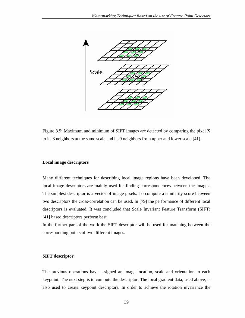
Watermarking Techniques Based on the use of Feature Point Detectors
39
Figure 3.5: Maximum and minimum of SIFT images are detected by comparing the pixel X
to its 8 neighbors at the same scale and its 9 neighbors from upper and lower scale [41].
Local image descriptors
Many different techniques for describing local image regions have been developed. The
local image descriptors are mainly used for finding correspondences between the images.
The simplest descriptor is a vector of image pixels. To compute a similarity score between
two descriptors the cross-correlation can be used. In [79] the performance of different local
descriptors is evaluated. It was concluded that Scale Invariant Feature Transform (SIFT)
[41] based descriptors perform best.
In the further part of the work the SIFT descriptor will be used for matching between the
corresponding points of two different images.
SIFT descriptor
The previous operations have assigned an image location, scale and orientation to each
keypoint. The next step is to compute the descriptor. The local gradient data, used above, is
also used to create keypoint descriptors. In order to achieve the rotation invariance the

Watermarking Techniques Based on the use of Feature Point Detectors
40
coordinates of the descriptor and the gradient information is rotated to line up with the
orientation of the keypoint. The gradient magnitude is weighted by a Gaussian function with
variance, which is dependent on keypoint scale. This data is then used to create a set of
histograms over a window centered on the keypoint. Figure 3.6 illustrates the computation
of keypoint descriptor. The Figure shows 2x2 array of orientation histograms.
Keypoint descriptors typically use a set of 16 histograms, aligned in a 4x4 grid, each with 8
orientation bins. This results in a feature vector containing 4x4 x8=128 elements.
Figure 3.6: This figure shows a 22 x descriptor array computed from a 88 x set of samples.
On the left image the gradient magnitude and orientation is computed at each image sample
point in a region around the keypoint location. They are weighted by a Gaussian window
(indicated by the circle). These samples are then accumulated into orientation histograms
summarizing the contents over 44 x subregions, as shown on the right. The length of each
arrow corresponds to the sum of the gradient magnitudes near that direction within the
region.

Watermarking Techniques Based on the use of Feature Point Detectors
41
3.3 Comparison of feature point detectors
There are several ways how the feature point detectors can be compared. In [80] the
repeatability score is used as a criterion for comparison of detectors. By this, the
repeatability score for a given pair of images is computed as a ratio between the number of
point-to-point correspondences and the minimum number of points detected in the images.
In [81] Lee made an evaluation of feature extraction techniques for robust watermarking.
They perform Bas’ approach [36] using tree different feature point detectors: Harris detector
used in original Bas’ approach, Mexican hat wavelet scale interaction method and SIFT
feature point detector. After feature extraction, the set of triangles is generated by Delaunay
tessellation. For all tree detectors, they compute the numbers of extracted triangles on
original image and compare it with the number of extracted triangles on distorted image.
The distorted image was obtained after applying the geometrical distortions, as well as
different filtering and JPEG compressions. It is shown that SIFT detector has a good
potential to be used in watermarking.
In this part the comparative evaluation of the scale-invariant feature point detectors:
SIFT and Harris-Affine, will be done. The aim of this comparison is to show which feature
point detector gives more robust feature points under different distortions. These points will
be used later for image watermarking. The software implementation of these feature point
detectors is used from [82]. Our evaluation will be performed for 10 images with the size of
512 x 512: barbara, boats, cameraman, couple, einstein, elaine, f16, goldhill, house and
lena (see Appendix D) image which are commonly used images in image processing
applications. On every test image, the different signal processing operations will be applied.
Among them are non-geometrical operations like: compressions (JPEG, JPEG2000),
filtering operation (Gaussian, median, wiener, trim mead mean), noise addition (salt’ n
pepper or Poisson) or geometrical distortion like: rotation, scaling, cropping or combination
of them. These images will be referred as distorted images. The feature points will be
extracted on the test image and on its distorted version using both feature extraction
methods. It will be measured how many corresponding feature points can be found on
original and distorted image.

Watermarking Techniques Based on the use of Feature Point Detectors
42
However, in our experiments we will not observe the total number of extracted
feature points. We will reduce it to the set of feature points with the largest characteristic
scale. In the next Chapter the watermark synchronization technique will be developed based
on use of feature points with the largest characteristic scale. The synchronization
information will be embedded into the circular neighborhood of the feature point, with
radius proportional to the characteristic scale. From this point of view it was more
reasonable to observe in our experiments only the feature point with the largest
characteristic scale.
The whole procedure is performed in the following steps:
1. The feature points will be extracted on original and on distorted image using
SIFT and Harris-Affine feature point detectors;
2. For every feature point extracted with this two detectors its characteristic scale
will be computed;
3. The points from the same image will be sorted in descending order by the
characteristic scale and first i ( }30,20,10{∈i ) points from this set will be
selected. Actually these points are points with the largest characteristic scale;
4. In order to compare the corresponding points on original and distorted image, the
SIFT descriptors for the selected points will be computed ( tSIFT for the test
image and dSIFT for the distorted image, where idit …… 1,1 == );
5. The i SIFT descriptors of test image will be compared with i SIFT descriptors
of distorted image. Matching will be performed applying the correlation. The
correlation coefficient between the SIFT descriptors will be computed:
thrSIFTSIFTcorr dt >),( (3.11)
6. If the correlation coefficient is grater then a threshold thr the matching points
are found. thr value is set to 0.9.
Figure 3.7shows the feature points with the largest characteristic scale extracted on
Lena image: (a), (c), (e) shows the first i points ( }30,20,10{∈i , respectively) with the
largest characteristic scale extracted with SIFT detector while (b), (d), (f) presents the first i
points ( }30,20,10{∈i , respectively) with the largest characteristic scale extracted with
Harris-Affine detector.
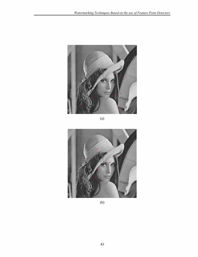
Watermarking Techniques Based on the use of Feature Point Detectors
43
(a)
(b)

Watermarking Techniques Based on the use of Feature Point Detectors
44
(c)
(d)

Watermarking Techniques Based on the use of Feature Point Detectors
45
(e)
(f)
Figure 3.7 Feature points extracted on Lena image: first 10 points with the largest
characteristic scale extracted with SIFT detector (a) and Harris-Affine detector (b); first 20
points with the largest characteristic scale extracted with SIFT detector (c) and Harris-
Affine detector (d); first 30 points with the largest characteristic scale extracted with SIFT
detector (e) and Harris-Affine detector (f).

Watermarking Techniques Based on the use of Feature Point Detectors
46
The results of the comparison of SIFT and Harris-Affine feature point detectors are
presented in the Tables A.1-A.3 (see Appendix A). Columns denoted with SF presents the
corresponding points found with SIFT detector and HA- the corresponding points found
with Harris-Affine detector.
In the Table A.1 the results for the following non-geometrical operations are
presented: jpg40- JPEG compression with quality factor 40; jpg50- JPEG compression with
quality factor 50; wc40- JPEG2000 compression with 0.4 bpp; wc50- JPEG2000
compression with 0.5 bpp; med- median filtering with 3x3 window size; gaus- Gaussian
filtering with 5x5 window size; wien- wiener filtering with 5x5 window size; trim-
trimmead mean filtering with 7x7 window size; salt- salt’ n pepper noise added to the
image, pois- possion noise added to the image.
In Table A.2 the results for the following operation are given: rot1- rotation for 5
degrees, rot2- rotation for 10 degrees, rot3- rotation for 15 degrees, rot4- rotation for 30
degrees, sc1- image scaling with new image size of 0.8 x image size, sc2- image scaling
with new image size of 0.9 x image size, sc3- image scaling with new image size of 1.2 x
image size, sc4- image scaling with new image size of 1.5 x image size.
In the Table A.3 the results of image cropping and combination of rotation, scaling
and cropping is presented. cr1- 5 % image cropping, cr2- 10 % image cropping, cr3- 15 %
image cropping, cr4- 20 % image cropping, cr5- 25 % image cropping, rs1- rotation of 5
degrees and scaling with new image size of 1.2 x image size; rs2- rotation of 15 degrees and
scaling with new image size of 0.9 x image size; rs3- rotation of 10 degrees and scaling with
new image size of 1.5 x image size; rs4- rotation of 30 degrees and scaling with new image
size of 0.8 x image size.
For every distortion separately the average number of all corresponding points for all
test images is computed. The computation is done separately for the first i points with the
largest characteristic scale ( 30,20,10=i ) and presented on the Figures 3.8-3.10.
Distortions are placed on x-axis and on y-axis are the average numbers of corresponding
points in percentage (computed as the total number of corresponding points for all images
divided with i and multiplied with 100%).
In the case of non-geometrical distortions in can be observed from the Figure 3.8 that
more corresponding points are found with Harris-Affine detector. However, the difference
between SF and HA is not very big and it can be concluded that both detectors give very
good results. Comparing the number of corresponding points for different sets of selected

Watermarking Techniques Based on the use of Feature Point Detectors
47
points with the largest characteristic scale, better results are obtained using only the 10=i
points then 20=i and 30=i points.
The performance of the detectors is not as good for geometrical distortions as with
the non-geometrical distortion (Figure 3.8, 3.9). For the most of the geometrical distortions
which consist of rotation, scaling or combinations of them, feature extraction method based
on SIFT detector gives more corresponding points then Harris-Affine. However, most of the
corresponding points which are found with Harris-Affine detector (without reducing the
observation point set on set of points with the largest characteristic scale) have actually
small characteristic scale. Comparing the number of corresponding points by i parameter
more points are obtained for 20=i , although the percentages of corresponding points for
10=i and 20=i are similar.
For the image cropping distortion the results for both detectors are very good (Figure
3.10). It can be observed that at least 50% of corresponding points can be found. The results
strongly depend of the points distribution over the image.
0
10
20
30
40
50
60
70
80
90
100
jp g 40 jp g 50 w c40 w c50 m ed g au s w ien trim salt p ois
D isto rtio n s
Cor
resp
ondi
ng p
oint
s (%
)
S IF T (10)H .-A. (10)S IF T(20)H .-A. (20)S IF T (30)H .-A. (30)
Figure 3.8: The average number of the corresponding points for all test images in the case of
non-geometrical distortions.

Watermarking Techniques Based on the use of Feature Point Detectors
48
0
10
20
30
40
50
60
70
80
90
100
rot1 rot2 rot3 rot4 sc1 sc2 sc3 sc4
Distortions
Cor
resp
ondi
ng p
oint
s (%
)
SIFT (10)H .-A . (10)S IFT (20)H .-A . (20)S IFT (30)H .-A . (30)
Figure 3.9: The average number of the corresponding points for all test images in the case of
rotation and image scaling distortions.
0
10
20
30
40
50
60
70
80
90
100
cr1 cr2 cr3 cr4 cr5 rs1 rs2 rs3 rs4
Distortions
Cor
resp
ondi
ng p
oint
s (%
)
SIFT (10)H.-A. (10)SIFT (20)H.-A. (20)SIFT (30)H.-A. (30)
Figure 3.10: The average number of the corresponding points for all test images in the case
of image cropping and combination of rotation and image scaling distortions.

Watermarking Techniques Based on the use of Feature Point Detectors
49
3.4 Chapter Summary
In this Chapter we introduce the implementation of feature point detectors in
watermarking. The brief overview of existing watermarking techniques, which are based on
the use of feature point detectors, is given. It is outlined which feature point detectors are
used in the watermarking field till the present. Then a new class of scale invariant feature
point detectors is introduced and particular SIFT feature point detector is described. After
that a comparison between two scale-invariant feature point detectors: SIFT and Harris-
Affine is performed. The aim of this comparison is to show which feature point detector
gives more robust feature points under different distortions. However, in the experiments
only the feature points will the largest characteristic scale were observed. It is shown that
the SIFT feature point detector gives more robust feature points and it is more suitable for
the development of the technique for recovering the watermark synchronization.
In the next Chapter the synchronization issue in watermarking will be introduced.
Firstly, and image registration technique will be described. Then the literature survey of
existing watermarking techniques, which consider the problem of synchronization without
access to the original image content, will be overview. A new synchronization technique
which is based on use of the feature points detected with SIFT detector will be developed
and tested in the next Chapter.
The synchronization issue in watermarking scheme
50
Chapter 4
The synchronization issue in watermarking
schemes
The resistance of watermarking schemes against geometrical distortions has been the
subject of quite research in the last ten years. Even the minor geometrical manipulation to
the watermarked image can dramatically reduce the ability of the receiver to detect the
watermark. The effect of geometrical distortions can be better understood by making the
analogy between the watermark and any communication system. In communication system
the synchronization between the encoder and decoder is related to the time-synchronization.
In watermarking system the synchronization principle can be applied and it is related to the
geometric synchronization. In order to detect watermark correctly, the watermark decoder
should use the same coordinates as on original image. If the received image is geometrically
manipulated the coordinates of the received image will be different from the original one.
As a consequence, the watermark detector will loose the synchronization. Hence, it is
required to implement a synchronization recovery technique as a pre-processing step at the
decoder side.
Roughly, the watermarking schemes dealing with the problem of synchronization
can be divided into two groups:
1. techniques that use the original image content (image registration techniques);
2. techniques without the access to the original image content.
In Section 4.1 an image registration technique is described and experimentally
tested. Section 4.2 gives an overview of the existing watermarking techniques, which

The synchronization issue in watermarking scheme
51
consider the problem of synchronization without access to the original image content. In
Section 4.3 the proposed synchronization technique is described and tested.
4.1 Image registration techniques
If the original image is available to the watermark detector, firstly, an image
registration technique can be used to establish point-by-point correspondence between the
original image and image possibly altered by unknown geometrical transformation (received
image). When the correspondence between the two images is found the parameters of the
undergone geometrical transformation can be estimated. From these parameters an inverse
geometrical transformation can be calculated and applied to the received image. After that,
the watermark detection procedure is performed.
In this part a registration method applied on original image and image possibly altered
by unknown geometrical transformation (received image), used in our work [42, 43] will be
briefly described:
1. On the original and distorted image the feature points are detected using the SIFT
feature point detector, described in the Chapter 3.
2. For every feature point, the corresponding SIFT descriptor is calculated. Array of
SIFT descriptors calculated for original image is denoted by 0SIFT and dSIFT for
the received image, where 21 1,1 ndno …… == . 1n and 2n are the total numbers
of feature points detected on original image and received image, respectively.
3. The comparison between each element of 0SIFT and dSIFT is performed applying
the correlation. The correlation coefficient between the 0SIFT and dSIFT ,
21 1,1 ndno …… == is computed:
∑ ∑
∑
= =
=
−−
−−=
128
1
128
1
2200
128
100
0
)()(
))((),(
i ididi
ididi
d
SIFTSIFTSIFTSIFT
SIFTSIFTSIFTSIFTSIFTSIFTcorr (4.1)
The synchronization issue in watermarking scheme
52
where 0SIFT and dSIFT are the mean values of 0SIFT and dSIFT . By this SIFT
descriptor of every feature point is vector of 128 elements.
4. If the correlation coefficient is grater then a threshold thr the corresponding points
are found. thr value is set to 0.9.
thrSIFTSIFTcorr d >),( 0 (4.2)
Now a few experiments will be performed in order to show ability of our method to
register the image after geometric distortion. In our experiments it is assumed that the
original image is transformed by an affine transformation.
An affine transformation can be expressed as:
⎥⎥⎥
⎦
⎤
⎢⎢⎢
⎣
⎡=
⎥⎥⎥
⎦
⎤
⎢⎢⎢
⎣
⎡
112
1
ff2
1
xx
xx
d
d
A (4.3)
⎥⎥⎥
⎦
⎤
⎢⎢⎢
⎣
⎡=
1002
1
2221
1211
ff x
x
taataa
A (4.4)
where 1x , 2x are the image coordinates which are transformed to the coordinates dx1 , dx2
using an affine matrix ffA . The coefficients 11a , 12a , 21a , 22a present the linear part of
transformation ( ffLA ); 1xt and
2xt are parameters of translation. The linear part ffLA of affine
matrix ffA can be expressed as combination of rotation, scaling and shearing transformation
with the corresponding parameters:
⎥⎦
⎤⎢⎣
⎡⎥⎦
⎤⎢⎣
⎡⎥⎦
⎤⎢⎣
⎡−
=⎥⎦
⎤⎢⎣
⎡=
101
00
))))
2
1
2221
1211ffL
ShS
Scos(θsin(θsin(θcos(θ
aaaa
x
xA (4.5)

The synchronization issue in watermarking scheme
53
Each of the parameters of the transformation can be computed:
11
21)aa
tan(θ −= for rotation (4.6)
221
2111
aaS x += , 1
2
)det( ffL
xx S
SA
= for image scaling (4.7)
)det( ffL
22211211
AaaaaSh +
= for shearing (4.8)
In order to determine the parameters of affine transformations it is enough to detect 3
corresponding points on original and received image.
Six combined affine geometrical attacks are performed. These attacks consist of
rotation, scaling, shearing, or combination of them with the image cropping. These attacks
are denoted as G1-G6 and the parameters of the affine transformations are given in the
Table 1. G1 is the shearing attack with 5.0=Sh ; G2 is the rotation attack with 30=θ ; G3
is the scaling attack with 8.021== xx SS ; G4 is the combination of rotation attack with
20=θ , scaling with 2.121== xx SS and cropping; G5 is combination of rotation with
45=θ , scaling with 3.11=xS , 9.0
2=xS ; G6 is combination of rotation 8=θ and scaling
5.021== xx SS .
In Figures 4.1-4.6 the six geometrical attacks are presented: (a) is the original Lena
image, (b) is geometrically transformed Lena image and (c) is the reconstructed image after
applying the inverse affine transform. The corresponding feature points are presented on
Figures (a) and (b). From the Figures it can be seen that for different distortion the different
corresponding feature points are found.
In Table 4.1 the following parameters are presented: the total number of feature
points extracted on original image (“fpo”); the total number of feature points extracted on
transformed image (“fpt”); the size of the transformed image; the total number of
corresponding points (“cp”); the parameters of applied affine transformation ( 11Oa , 12Oa ,
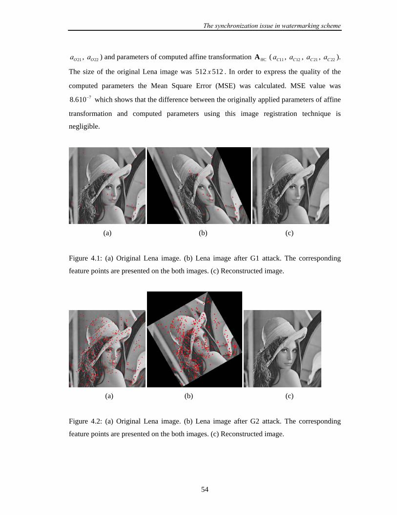
The synchronization issue in watermarking scheme
54
21Oa , 22Oa ) and parameters of computed affine transformation ffCA ( 11Ca , 12Ca , 21Ca , 22Ca ).
The size of the original Lena image was 512512 x . In order to express the quality of the
computed parameters the Mean Square Error (MSE) was calculated. MSE value was 7106.8 − which shows that the difference between the originally applied parameters of affine
transformation and computed parameters using this image registration technique is
negligible.
(a) (b) (c)
Figure 4.1: (a) Original Lena image. (b) Lena image after G1 attack. The corresponding
feature points are presented on the both images. (c) Reconstructed image.
(a) (b) (c)
Figure 4.2: (a) Original Lena image. (b) Lena image after G2 attack. The corresponding
feature points are presented on the both images. (c) Reconstructed image.

The synchronization issue in watermarking scheme
55
(a) (b) (c)
Figure 4.3: (a) Original Lena image. (b) Lena image after G3 attack. The corresponding
feature points are presented on the both images (c) Reconstructed image.
(a) (b) (c)
Figure 4.4: (a) Original Lena image. (b) Lena image after G4 attack. The corresponding
feature points are presented on the both images. (c) Reconstructed image.
(a) (b) (c)
Figure 4.5: (a) Original Lena image. (b) Lena image after G5 attack. The corresponding
feature points are presented on the both images (c) Reconstructed image.

The synchronization issue in watermarking scheme
56
(a) (b) (c)
Figure 4.6: (a) Original Lena image. (b) Lena image after G6 attack. The corresponding
feature points are presented on the both images (c) Reconstructed image.
Table 4.1: The affine computation
fpo fpt size cp 11Oa 12Oa 21Oa 22Oa 11Ca 12Ca 21Ca 22Ca
G1 515 550 512x768 37 1 0 0.5 1 1.0023 0.0011 0.5002 1.0010
G2 515 582 701x701 340 0.8666 -0.5 0.5 0.8666 0.8661 -0.5004 0.5000 0.8655
G3 515 363 409x409 152 0.8 0 0 0.8 0.7987 -0.0003 0.0001 0.7986
G4 515 778 614x614 187 1.1276 0.41 -0.41 1.1276 1.1268 -0.4097 0.4101 1.1272
G5 515 646 652x941 79 0.9192 0.6364 -0.9192 0.6354 0.9180 0.6354 -0.9207 0.6368
G6 515 166 293x293 49 0.4951 0.0696 -0.0696 0.4951 0.4955 0.0695 -0.0695 0.4945
It is shown from our experiments that this image registration technique can successfully
calculate the parameters of affine transformation. Using the correlation threshold above 0.9
to measure the similarity between the SIFT descriptors, only the corresponding and some
nearly corresponding points will be extracted on original and transformed image. The
percentage of nearly corresponding points is very low and it does not have influence of the
computation of the affine parameters because the larger set of points is included in the
computation of the affine parameters, then it is necessary. In the Next Chapters it will be
shown how this technique can increase the robustness of the proposed watermarking
algorithms on geometrical distortions.

The synchronization issue in watermarking scheme
57
4.2 Watermarking techniques dealing with the problem of
synchronization without access to the original image
content
In the following Section a survey of the watermarking techniques claiming resistance
to geometrical distortions will be presented. These techniques do not use the original image
content. The classification will be organized according to the common approaches. Some
techniques can be classified in more then one class because they combine several different
approaches.
4.2.1 Exhaustive search
This approach considers all possible geometrical distortions that could take place.
The inverse transformation is applied to the received image and the watermark detection,
too. The embedded watermark is extracted choosing the best detection confidence value
(e.g. correlation coefficient), which is beyond the appropriate threshold. The main
drawbacks of these approaches are increased computational costs and possibility of false
detection. The possibility of false watermark detection under exhaustive search is deeply
studied in [83, 84, 85].
Usually in these approaches the transformation sets are limited to translation, scaling
and rotation. In order to decrease the computational costs and to observe more complex
transformations, detection procedure can be performed on smaller image regions [86].
4.2.2 Periodical sequences
One strategy to solve the synchronisation problem introduced by geometrical
distortions is to add redundancy during the embedding process. This redundancy can be
used to localize the position of the watermark and to improve the detection stage [87, 88,

The synchronization issue in watermarking scheme
58
89]. In these approaches the search for synchronization is limited to one repetition period. In
[90] the periodical watermark insertion is used to perform the synchronization. This scheme
is designed against StirMark attack, which introduce small local geometrical distortions.
The correlation technique with sliding windows (commonly used in communication in order
to recover synchronization) is implemented. The image is divided in blocks and marks are
embedded in these blocks. The technique of sliding window is implemented on image
blocks and the correlation between the image block of received image, possibly containing
the watermark and the block with the watermark is measured. If the mark is detected in the
block the location of the mark in the neighbor block is initialized by the previous location.
4.2.3 Invariant domains
The main idea of watermarking in the transform invariant domain is to perform the
watermark embedding or detection in the domain invariant to geometrical transformations.
One of the examples is to apply a Fourier-Mellin transform (see Appendix C) to the DFT
magnitude of the original image spectrum [27, 28]. In Fourier domain magnitude spectrum
is insensitive to translation, image scaling produces inverse scaling in frequency domain and
image rotation causes the spectrum rotation for the same angle. Transforming the Cartesian
coordinates of the Fourier domain in log-polar, image scaling and rotation become the
translation. Applying again the Fourier transformation to the log-polar representation of the
magnitude spectra, the Fourier-Mellin domain is obtained (see Figure 4.7). Fourier-Mellin
domain is rotation, scale and translation invariant. The main problem with the
implementation of discrete Fourier-Mellin transformation is that the forward and inverse
transformations are not straightforward. The logarithmic sampling of the log-polar mapping
must be carefully implemented in order to avoid the interpolation errors (see Figure 4.10).
Another possibility to obtain an invariant domain was the implementation of the log-
log mapping of the Fourier spectra [29]. Such a representation was insensitive to image
cropping, scaling, modification of aspect ratio, but not invariant to rotation.
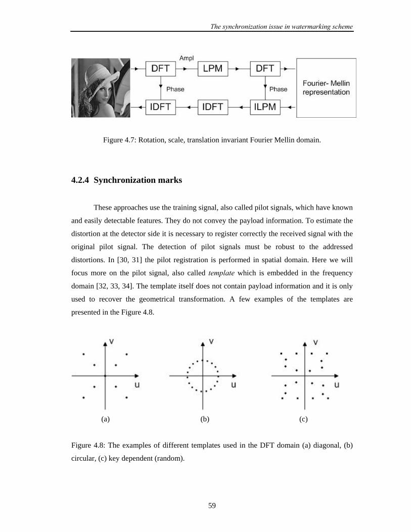
The synchronization issue in watermarking scheme
59
Figure 4.7: Rotation, scale, translation invariant Fourier Mellin domain.
4.2.4 Synchronization marks
These approaches use the training signal, also called pilot signals, which have known
and easily detectable features. They do not convey the payload information. To estimate the
distortion at the detector side it is necessary to register correctly the received signal with the
original pilot signal. The detection of pilot signals must be robust to the addressed
distortions. In [30, 31] the pilot registration is performed in spatial domain. Here we will
focus more on the pilot signal, also called template which is embedded in the frequency
domain [32, 33, 34]. The template itself does not contain payload information and it is only
used to recover the geometrical transformation. A few examples of the templates are
presented in the Figure 4.8.
(a) (b) (c)
Figure 4.8: The examples of different templates used in the DFT domain (a) diagonal, (b)
circular, (c) key dependent (random).

The synchronization issue in watermarking scheme
60
In the template based approaches it is important to resolve the following problems:
- Where to embed such a template to satisfy the trade-off between the visibility and
robustness. Template points should be embedded as local peaks in its neighborhood.
- How to detect peaks after geometrical attacks possibly followed by lossy
compression.
- Design an efficient and fast template matching algorithm for estimation of the
parameters of affine transformation [91].
In [92] template registration was performed using log-polar and log-log mapping.
For improving the efficiency of the template registration, in our work [93] we propose the
implementation of Radon transform (see Appendix B). The Radon transform is
implemented on the Fourier spectrum in order to detect the angle of image rotation. After
that the searching for the template points is performed. The algorithm has the following
steps:
- Apply DFT on the original and received image.
- In order to calculate the angle of the image rotation, apply the Radon Transform on
the DFT spectra of original and received image. The difference between the peaks of
the Radon transform will give the angle of rotation.
- Rotate the received image for the calculated angle.
- Extract the local peaks of the DFT spectra. The extracted peaks include the template
peaks, which are possibly affected by a geometrical transform, and many other
peaks, which originally exist in the DFT spectra of the image.
- Search for the template points and calculate the new distance between the template
points.
- The ratio between the new and old distance of the template points will correspond to
the scaling parameter in DFT domain and the inverse scaling in spatial domain.
In Figure 4.9.a an example of the Radon Transform of the Lena image is presented.
In Figure 4.9.b the corresponding graph with the Radon Transform of the Lena image
rotated for 30 is presented. By extracting the peaks of the Radon Transform of the original

The synchronization issue in watermarking scheme
61
and rotated image and by subtracting them the angle of the rotation can be calculated. From
Figure 4.9 it is obvious that the unknown angle ( 30 ) can be simply determined.
(a)
(b)
Figure 4.9: Radon Transform of: (a) Lena image; (b) rotated Lena image for 30

The synchronization issue in watermarking scheme
62
One of the drawbacks of the template based approaches is its security. Even with the
usage of key-dependent template, an attacker can easily predict the template without
knowledge about the key and remove it. One example of such an attack is template removal
attack [94].
Another synchronization possibility is provided by the approaches based on self-
reference watermarks. They do not use any additional template. The watermark itself is
arranged in the special spatial structure, which has desired statistical properties. Based on
the watermark design and the watermark statistic used for the estimation the parameters of
affine transformation, the following types of self-reference watermark can be distinguished:
- self-reference watermark based on 4 times repeated patterns and affine estimation
based on autocorrelation function (ACF) [95];
- periodic watermarks with any geometry and affine estimation based on the
magnitude watermark spectrum [96, 97];
- self-similar patterns or patterns with a special spatial structure [87, 98, 99].
In [95] the same watermark is four times embedded in the image, which enables to
have nine peaks in the ACF that are used to detect the parameters of undergone geometrical
transformation. The need of computing the two times DFT and reduced robustness in the
case of lossy compression are some problems with this approach. To improve the robustness
after lossy compression the algorithms based on magnitude spectrum of periodical
watermarks are proposed [97]. The magnitude spectrum of the estimate watermark is
computed. Due to the periodicity of the embedded information the magnitude spectrum
showed aligned and regularly spaced peaks. If the affine distortion is applied on the
watermarked image, the peaks layout will be rescaled, rotated, or shared but alignments will
be preserved. Actually it is easy to estimate the affine geometrical distortions from these
peaks by fitting the alignments and estimating periods.
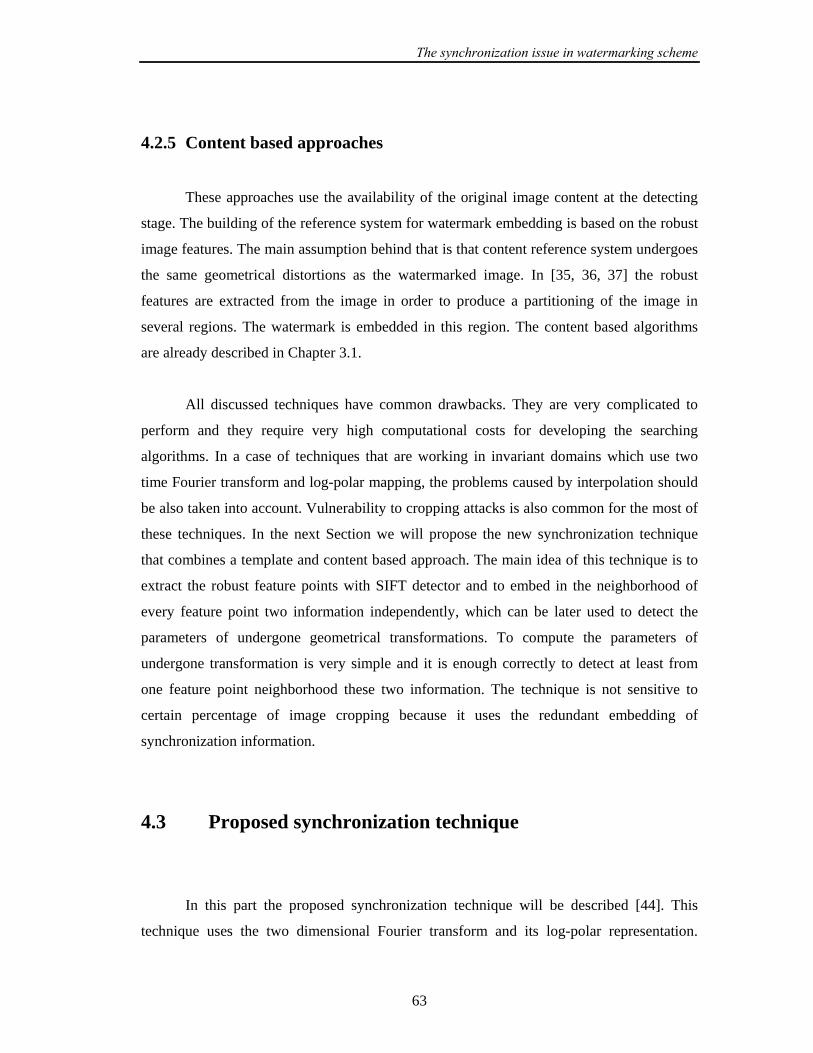
The synchronization issue in watermarking scheme
63
4.2.5 Content based approaches
These approaches use the availability of the original image content at the detecting
stage. The building of the reference system for watermark embedding is based on the robust
image features. The main assumption behind that is that content reference system undergoes
the same geometrical distortions as the watermarked image. In [35, 36, 37] the robust
features are extracted from the image in order to produce a partitioning of the image in
several regions. The watermark is embedded in this region. The content based algorithms
are already described in Chapter 3.1.
All discussed techniques have common drawbacks. They are very complicated to
perform and they require very high computational costs for developing the searching
algorithms. In a case of techniques that are working in invariant domains which use two
time Fourier transform and log-polar mapping, the problems caused by interpolation should
be also taken into account. Vulnerability to cropping attacks is also common for the most of
these techniques. In the next Section we will propose the new synchronization technique
that combines a template and content based approach. The main idea of this technique is to
extract the robust feature points with SIFT detector and to embed in the neighborhood of
every feature point two information independently, which can be later used to detect the
parameters of undergone geometrical transformations. To compute the parameters of
undergone transformation is very simple and it is enough correctly to detect at least from
one feature point neighborhood these two information. The technique is not sensitive to
certain percentage of image cropping because it uses the redundant embedding of
synchronization information.
4.3 Proposed synchronization technique
In this part the proposed synchronization technique will be described [44]. This
technique uses the two dimensional Fourier transform and its log-polar representation.
The synchronization issue in watermarking scheme
64
Before we start with the description of the proposed technique the two dimensional Fourier
transform with its properties will be introduced in Subsection 4.3.1. The log-polar
representation of the Fourier spectra will be also given in 4.3.1. After that the
synchronization technique will be described in details in Subsections 4.3.2 and 4.3.3. In
Subsection 4.3.4 the relevant parameters of the proposed technique will be discussed. The
proposed technique will be tested in Subsection 4.3.5 and compared with other
synchronization techniques in Subsection 4.3.6.
4.3.1 Fourier transform
In this Section, we shall describe the Fourier transform in some detail highlighting
those properties, which make it particularly suitable to digital image watermarking.
Let the image be a real valued continuous function ),I( 21 xx defined on an integer-
valued Cartesian grid 110 Nx << , 220 Nx << . The Discrete Fourier Transform (DFT) is
defined as follows:
∑∑−
=
−
=
−−=1
0
1
0
/2/221
2121
1
1
2
2
222111),I(1),(N
x
N
x
NωπxjNωπxjexxNN
ωωF (4.9)
The inverse transform is:
∑∑−
=
−
=
+=1
0
1
0
/2/22121
1
1
2
2
222111),(),(N
ω
N
ω
NωπxjNωπxjeωωFxxI (4.10)
The DFT of a real image is generally complex valued. This leads to magnitude and phase
representation for the image:
),(),( 2121mp ωωFωωA = (4.11)
),(),( 2121 ωωFωωΦ ∠= (4.12)

The synchronization issue in watermarking scheme
65
For the real images the Fourier transform has certain symmetries:
),(),( 21mp21mp ωωAωωA −−= ∗ (4.13)
The symbol ( ∗ ) indicates complex conjugation. For real signals equation (4.13) leads
directly to:
),(),( 21mp21mp ωωAωωA −−= (4.14)
),(),( 2121 ωωΦωωΦ −−−= (4.15)
General Properties of the Fourier Transform
It is very important to study the effect of an arbitrary linear transform on the
spectrum of an image. In the case of 21 NN = (i.e. square blocks) the kernel of the DFT
contains a term of the form:
[ ] ⎥⎦
⎤⎢⎣
⎡=+
2
1212211 ωω
xxωxωx (4.16)
If we compute a linear transform on the spatial coordinates:
⎥⎦
⎤⎢⎣
⎡→⎥
⎦
⎤⎢⎣
⎡
2
1
2
1
xx
Txx
(4.17)
then the value of the DFT will not be changed if:
⎥⎦
⎤⎢⎣
⎡→⎥
⎦
⎤⎢⎣
⎡ −
2
11
2
1 )(ωω
Tωω T (4.18)
The synchronization issue in watermarking scheme
66
FFT Rotation
Consider a rotation matrix:
⎥⎦
⎤⎢⎣
⎡ −=
θθθθ
Tcossinsincos
(4.19)
Therefore,
⎥⎦
⎤⎢⎣
⎡ −=−
θθθθ
T T
cossinsincos
)( 1 (4.20)
Rotating the image through an angle θ in the spatial domain causes the Fourier
representation to be rotated through the same angle.
)cossin,sincos()cossin,sincos( 21212121 θxθxθxθxIθωθωθωθωF +−↔+− (4.21)
Note that the grid is rotated so the value of the image at the new grid points may not be
defined. The value of the image at the nearest valid grid point can be estimated by
interpolation.
FFT Scale
Consider a scaling matrix:
⎥⎦
⎤⎢⎣
⎡=
2
1
00
x
x
SS
T (4.22)
Therefore,
The synchronization issue in watermarking scheme
67
⎥⎥⎥⎥
⎦
⎤
⎢⎢⎢⎢
⎣
⎡
=−
2
1
10
01
)( 1
x
xT
S
ST (4.23)
Hence, scaling the axes in the spatial domain causes an inverse scaling in the frequency
domain.
),(),(121
21 ρxρxIρω
ρωF
ρ↔ (4.24)
FFT Shearing
Consider a shearing matrix:
⎥⎦
⎤⎢⎣
⎡=
101
ShT (4.25)
Therefore,
⎥⎦
⎤⎢⎣
⎡ −=−
101
)( 1 ShT T (4.26)
Therefore, shearing the 2x coordinates of the spatial coordinates inverse shearing the 1ω
coordinates of the frequency coordinates (and vice versa).
FFT Translation
Shifts in the spatial domain cause a linear shift in the phase component.
[ ] ),I((exp),(2121 212121 xxxx txtxωtωtjωωF ++↔+− (4.27)
The synchronization issue in watermarking scheme
68
Note that both ),( 21 ωωF and its dual ),(I 21 xx are periodic functions so it is implicitly
assumed that translations cause the image to be “wrapped around". We shall refer to this as
a circular translation or a cyclic shift. From property (4.27) of the Fourier transform it is
clear that spatial shifts affect only the phase representation of an image. This leads to the
well-known result that the magnitude of the Fourier transform is a circular translation
invariant.
Log-polar mapping
Consider a point 221 ),( ℜ∈xx and define:
θex μ cos1 = (4.28a)
θex μ sin2 = (4.28b)
where ℜ∈μ and πθ 20 << . One can see that for every point ),( 21 xx there is a point
),( θμ that uniquely corresponds to it. The new coordinate system has the following
properties:
Scaling is converted to a translation.
),log(),( 21 θρμρxρx +↔ (4.29)
Rotation is converted to a translation.
),())cos()sin(),sin()cos(( 2121 δθμδxδxδxδx +↔+− (4.30)
How does a log polar map look like?
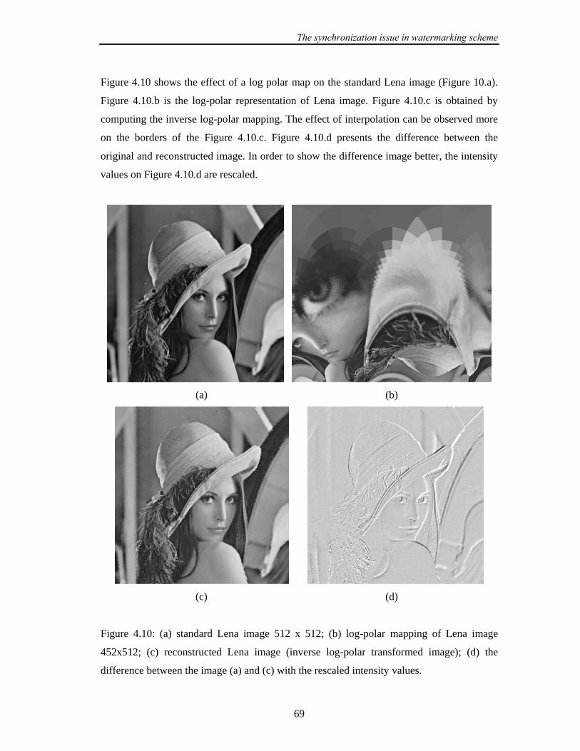
The synchronization issue in watermarking scheme
69
Figure 4.10 shows the effect of a log polar map on the standard Lena image (Figure 10.a).
Figure 4.10.b is the log-polar representation of Lena image. Figure 4.10.c is obtained by
computing the inverse log-polar mapping. The effect of interpolation can be observed more
on the borders of the Figure 4.10.c. Figure 4.10.d presents the difference between the
original and reconstructed image. In order to show the difference image better, the intensity
values on Figure 4.10.d are rescaled.
(a) (b)
(c) (d)
Figure 4.10: (a) standard Lena image 512 x 512; (b) log-polar mapping of Lena image
452x512; (c) reconstructed Lena image (inverse log-polar transformed image); (d) the
difference between the image (a) and (c) with the rescaled intensity values.

The synchronization issue in watermarking scheme
70
4.3.2 Description of the proposed synchronization technique
In this part the proposed synchronization technique will be described. It combines
the template based and content based approach. Firstly, the feature points on original image
are extracted using the SIFT detector. In Chapter 3.3 it is shown that the feature points
extracted with SIFT detector are robust on filtering, compression and geometrical
transformation. Then the 10 feature points with the largest characteristic scale are selected.
Around every feature point the circle regions are extracted. The radius of the circle will be
equal to the integer value of the characteristic scale multiplied with a constant. This constant
will be kept secret. In our case it will be set to one. This circle image region with the feature
point in its centre will be firstly zero-padded to the size 256 x 256 and then DFT
transformed. The zero padding is performed in order to obtain the desired properties of the
Fourier spectra (4.16-4.27). The Cartesian coordinates of the DFT spectra will be
transformed to polar. There are two reasons why we have extracted circle region around the
feature point rather then the block-based region. Firstly, in the case of geometrical
transformation (rotating, scaling) using the circular region the image region most similar to
the original one will be extracted. Secondly, the DFT spectra will not strongly depend on the
squared region borders.
In the DFT spectra two template point structures will be embedded carrying the
information about the reference angle and the information about the characteristic scale.
Every template point structure will be placed on the line, which runs through the centre of
the polar grid. The position of the lines will be determined by different angles (see Figure
4.11). First line is determined by user defined reference angle. The same reference angle
will be used in all regions around the feature points. The second angle, (denoted as “scaling”
angle) will be secretly encoded and it will present the information about the characteristic
scale of the feature point. This angle will determine the position of the second line where
template points will be embedded. Actually, the idea behind it is that when we extract
correctly the regular template points in the template extraction procedure, the information
about the location of template points will give us the embedded reference and scaling angle.
After the template embedding procedure, the selected image part will be inverse
DFT transformed, cropped to the original size and added back to the original image.
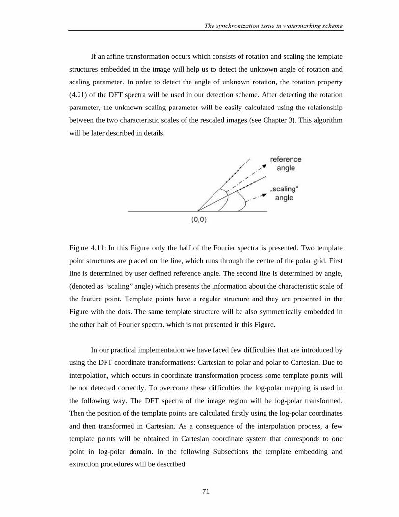
The synchronization issue in watermarking scheme
71
If an affine transformation occurs which consists of rotation and scaling the template
structures embedded in the image will help us to detect the unknown angle of rotation and
scaling parameter. In order to detect the angle of unknown rotation, the rotation property
(4.21) of the DFT spectra will be used in our detection scheme. After detecting the rotation
parameter, the unknown scaling parameter will be easily calculated using the relationship
between the two characteristic scales of the rescaled images (see Chapter 3). This algorithm
will be later described in details.
Figure 4.11: In this Figure only the half of the Fourier spectra is presented. Two template
point structures are placed on the line, which runs through the centre of the polar grid. First
line is determined by user defined reference angle. The second line is determined by angle,
(denoted as “scaling” angle) which presents the information about the characteristic scale of
the feature point. Template points have a regular structure and they are presented in the
Figure with the dots. The same template structure will be also symmetrically embedded in
the other half of Fourier spectra, which is not presented in this Figure.
In our practical implementation we have faced few difficulties that are introduced by
using the DFT coordinate transformations: Cartesian to polar and polar to Cartesian. Due to
interpolation, which occurs in coordinate transformation process some template points will
be not detected correctly. To overcome these difficulties the log-polar mapping is used in
the following way. The DFT spectra of the image region will be log-polar transformed.
Then the position of the template points are calculated firstly using the log-polar coordinates
and then transformed in Cartesian. As a consequence of the interpolation process, a few
template points will be obtained in Cartesian coordinate system that corresponds to one
point in log-polar domain. In the following Subsections the template embedding and
extraction procedures will be described.

The synchronization issue in watermarking scheme
72
4.3.2.1 Template embedding algorithm
The embedding algorithm is performed in the following steps:
- Find the feature points on original image using SIFT detector.
- Select the first 10 points with the largest characteristic scale.
- Around every feature point select 10 non-overlapping circle regions, where the
radius is equal to the integer value of characteristic scale multiplied with a constant.
Set this constant to one. If the point region overlaps with another point region
already selected exclude this point region.
- Every selected point region pad with zeros to the size 256256 x .
- Apply DFT and select the magnitude spectra.
- Select the reference angle rθ and encode the characteristic scale:
css oe += (4.31)
where os is original characteristic scale, es is encoded value and c is arbitrary
selected integer constant, that is kept secret. Integer value of es will be referred to
“scaling” angle sθ . The value of the reference angle rθ will be the same for all
feature point regions and sr θθ > .
- Transform the DFT magnitude spectra in log-polar coordinates.
- The template points in log-polar domain will lie on the line which is determined by
rθ and sθ . According to the angles rθ and sθ calculate the positions of the template
points in log-polar coordinates and then transform them to the Cartesian. The
template points will be placed in the higher part of the DFT spectra even beyond the
spectra of the non zero-padded feature point region (see one example on Figure
4.12).
- Embed the template points in the magnitude spectra of the image region according to
the calculated position in Cartesian coordinate system.

The synchronization issue in watermarking scheme
73
alfaxxfxxf iiiin += ),(),( 2121 (4.32)
where alfa is the template strength and it will be later discussed. ),( 21 ii xxf are the
DFT magnitudes of the selected template points and ),( 21 iin xxf are the new
modified magnitudes of the DFT spectra, where tNi 1= and tN is the total
number of template points.
Figure 4.12. One example of embedded template points in log-polar coordinates of
Fourier spectra.
- Embed the same template points also in conjugate-complex part of DFT spectra in
order to obtain the real image part (see equation (4.14)).
- Apply the inverse DFT transform of the spectra of the image region, crop it to its
original size and add to the original image.
4.3.2.2 Template extraction algorithm
In this part the detection algorithm will be performed on received image, which is
possibly affine transformed image, which contain the template structure. The template
extraction algorithm is described as follows:

The synchronization issue in watermarking scheme
74
- Find the feature points on received image using SIFT detector.
- Select the first 10 points with the largest characteristic scale.
- Around every feature point select 10 non-overlapping circle regions, where the
radius is equal to the integer value of characteristic scale multiply with the constant.
Set constant to one.
- Every selected point region pad with zeros to the size 256256 x .
- Apply DFT and select the magnitude spectra.
- Transform the DFT magnitude spectra in log-polar coordinates.
- From the highest region of log-polar spectra calculate the four angles that present
new reference angle nrθ , new scaling angle nsθ and the shifted angles ( nrθ and nsθ )
for 180 grad coming from the symmetry of the DFT spectra.
The calculation of the reference and scaling angle is performed in the following way:
- Compute the one dimensional mask vector tmask that represents the template points
in the log-polar domain.
- For every angle from the highest part of log polar spectra select an array ip ,
360,,1…=i . The array ip presents actually the column vector in log-polar domain.
- Apply the cross correlation between the mask array tmask and selected array ip :
),( iti pmaskxcorrc = (4.33)
where the cross correlation function xcorr for two arrays 1y and 2y with length yN
and without using the normalization is given by:
⎪⎩
⎪⎨⎧
<−
≥+== ∑−−
=
∗
0),(
0),()()(),(
12
21
1
021
21
ττR
τiyτiyτRyyxcorryy
τN
iyy
y
(4.34)
where )12(,,1 −= yNτ … .

The synchronization issue in watermarking scheme
75
- Save the maximal value of cross correlation in an array 360,,1},{ …== icC i .
- Find the 4 maximal values over the entire array C , which represent the reference
angle, scaling angle and the shifted angles.
- The reference angle has always higher value then the scaling angle (defined in the
template embedding procedure) which implies that nsnr θθ > .
When the geometric transformation occurs which consists of rotation, scaling or
combination of them, the angle of rotation and scaling parameter can be calculated for every
selected region. Using the rotation property of the DFT spectra (equation 4.21) the
difference between the new- and old reference angle ( nrθ and rθ , respectively) presents the
parameter of image rotation rotθ :
rnrrot θθθ −= (4.35)
The parameter of image scaling will be computed in a different way. Let os be the original
characteristic scale and es is the encoded image scale. Let nsθ is the new calculated scale
angle. Using the rotation property of the DFT spectra (equation 4.21):
rotorotens θcsθsθ ++=+= (4.36)
The integer value of the original characteristic scale can be calculated as:
rotnso θcθs −−= (4.37)
Using the relationship between the two characteristic scales of the rescaled images.
oacal sss /= (4.38)
where as is the integer value of the characteristic scale of selected feature point. The scaling
parameter cals is computed according to the equation (4.38).
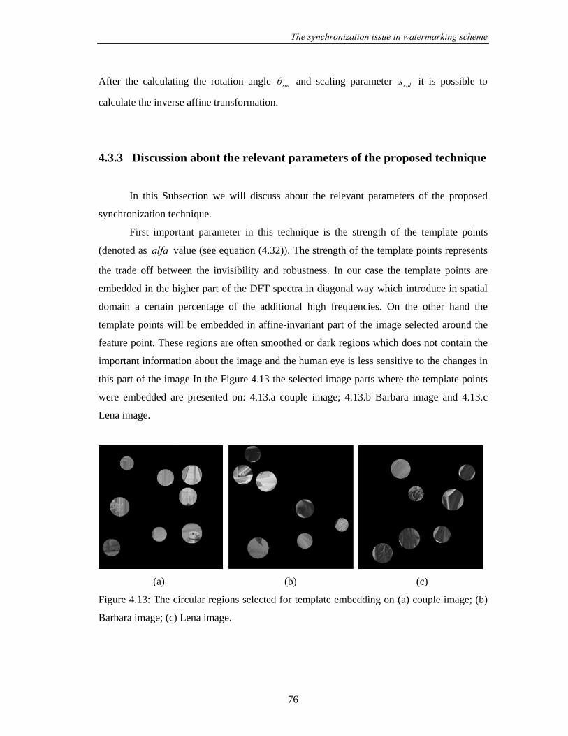
The synchronization issue in watermarking scheme
76
After the calculating the rotation angle rotθ and scaling parameter cals it is possible to
calculate the inverse affine transformation.
4.3.3 Discussion about the relevant parameters of the proposed technique
In this Subsection we will discuss about the relevant parameters of the proposed
synchronization technique.
First important parameter in this technique is the strength of the template points
(denoted as alfa value (see equation (4.32)). The strength of the template points represents
the trade off between the invisibility and robustness. In our case the template points are
embedded in the higher part of the DFT spectra in diagonal way which introduce in spatial
domain a certain percentage of the additional high frequencies. On the other hand the
template points will be embedded in affine-invariant part of the image selected around the
feature point. These regions are often smoothed or dark regions which does not contain the
important information about the image and the human eye is less sensitive to the changes in
this part of the image In the Figure 4.13 the selected image parts where the template points
were embedded are presented on: 4.13.a couple image; 4.13.b Barbara image and 4.13.c
Lena image.
(a) (b) (c)
Figure 4.13: The circular regions selected for template embedding on (a) couple image; (b)
Barbara image; (c) Lena image.
The synchronization issue in watermarking scheme
77
The value of the template strength should be carefully selected. Firstly the template
points after embedding in DFT magnitude spectra go through the process of the inverse
DFT transform, cropping to its original size, and forward transforming in order to detect the
template points. As a consequence of the cropping the amplitude of the template points will
be reduced. The alfa should not be too small because it would be very difficult to
distinguish the template points from the neighboring points. If the alfa value is to high the
visual artefacts will be detectable on image. In our case we have calculated separately alfa
value for every selected image region:
201DFTm
alfa = (4.39)
where 1DFTm was the maximal value of the 1DFT spectra. 1DFT was obtained from the DFT
spectra of the image region in that way that the maximal value of the DFT region spectra is
set to zero. The equation (4.39) is experimentally obtained as a trade off of invisibility and
robustness.
The second parameter, which should be considered, is related to the detection of the
template points. In our practical realization we will not observed the entire DFT spectra of
the image region in log-polar domain. Only the component of the DFT spectra which
magnitude is higher than a threshold will be observed. If the threshold value is to small,
more spectral components will be passed through and it will be more difficult to distinguish
the template points from other DFT components. If the threshold value is to high there
would be no template points. Also abovementioned effect of cropping should be also taken
in consideration. The threshold value should be smaller then 20/1DFTm . Also the effects of
image scaling (see equation (4.24)) which have the influence on the magnitude of the DFT
spectra should be also considered in establishing the threshold value. In our practical
realization the threshold value was iteratively selected for every image region. The threshold
value was set at the beginning to 1/1 rDFT pm and observed how many peaks are obtained. If
there is no cross correlation peaks (see equation (4.34)) the threshold value was increased. A
procedure stops if the peaks are detected or if the threshold value is approximately around
the 2/1 rDFT pm . The values for 1rp and 2rp are experimentally obtained with 401 =rp and

The synchronization issue in watermarking scheme
78
2302 =rp . The incrementing step was set to 10. A more intelligent method that adaptively
selects the threshold value and spares the computation time should be further developed.
In our experiments the distance between the template points in log-polar map was 3.
Also the template structure, which has 10 template points in log-polar representation, is
used.
(a)
(b)
Figure 4.14: The peaks of cross-correlation function for the region where (a) template points
were embedded; (b) no template points were embedded.

The synchronization issue in watermarking scheme
79
In Figure 4.14. a typical representation of cross correlation peaks is given. In this
case it was easy to detect the cross correlation peaks that correspond to the scaling and
reference angle. In our experiments we were always able to obtain at least one image region
from which we could clearly extract the cross correlation peaks. If the image region does
not contain the template points, the corresponding cross correlation function gives no peaks,
like in the Figure 4.14.b.
(a)
(b)
Figure 4.15: (a) Originally embedded template points in log-polar domain of Fourier
spectra. (b) Log-polar representation of the region where template points were not
embedded.

The synchronization issue in watermarking scheme
80
In Figure 4.15.a the extracted template points in log-polar domain are presented.
Figure 4.15.b presents the log-polar representation of the DFT spectra of the circular image
region where the template points were not embedded.
Figures 4.14 and 4.15 are obtained for the Lena image. From the Figure 4.14.a it can
be seen that the reference angle was 45 . The value of characteristic scale for that image
region was 43.42. From the equation (4.31) 43)42.43int( ==os ; 10−=c ; and the encoded
scaling angle was 33=es . This encoded scaling angle can be seen on Figure 4.14.a as the
first peak of cross-correlation function.
(a)
(b)
Figure 4.16: (a) Template peaks extracted after geometrical distortion, which consists of
rotation with 5−=θ and scaling 1.121== xx SS . (b) corresponding cross-correlation peaks.
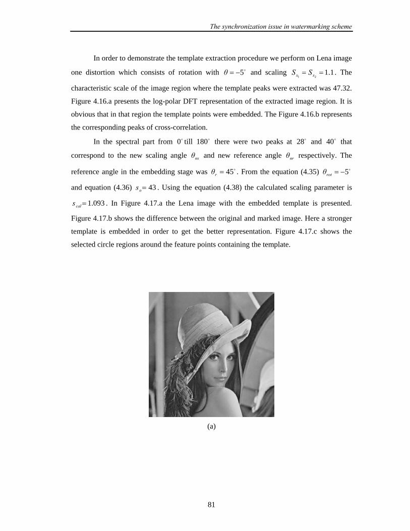
The synchronization issue in watermarking scheme
81
In order to demonstrate the template extraction procedure we perform on Lena image
one distortion which consists of rotation with 5−=θ and scaling 1.121== xx SS . The
characteristic scale of the image region where the template peaks were extracted was 47.32.
Figure 4.16.a presents the log-polar DFT representation of the extracted image region. It is
obvious that in that region the template points were embedded. The Figure 4.16.b represents
the corresponding peaks of cross-correlation.
In the spectral part from 0 till 180 there were two peaks at 28 and 40 that
correspond to the new scaling angle nsθ and new reference angle nrθ respectively. The
reference angle in the embedding stage was 45=rθ . From the equation (4.35) 5−=rotθ
and equation (4.36) 43=os . Using the equation (4.38) the calculated scaling parameter is
093.1=cals . In Figure 4.17.a the Lena image with the embedded template is presented.
Figure 4.17.b shows the difference between the original and marked image. Here a stronger
template is embedded in order to get the better representation. Figure 4.17.c shows the
selected circle regions around the feature points containing the template.
(a)

The synchronization issue in watermarking scheme
82
(b)
(c)
Figure 4.17: (a) Lena image with embedded template points; (b) difference between the
original and marked image; (c) circle regions around the feature points containing the
template.
4.3.4. Testing results
The method was tested on the geometrical transformation and image compression.
The geometrical attacks are the same as in the Chapter 3: rotations with different angles
(rot1- 5º , rot2- 10º, rot3- 15º, rot4- 30º), scaling transform with different scaling operations
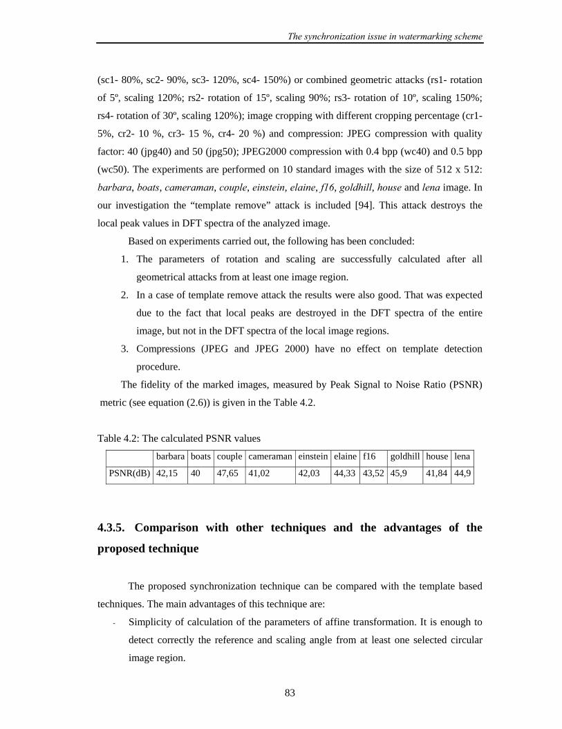
The synchronization issue in watermarking scheme
83
(sc1- 80%, sc2- 90%, sc3- 120%, sc4- 150%) or combined geometric attacks (rs1- rotation
of 5º, scaling 120%; rs2- rotation of 15º, scaling 90%; rs3- rotation of 10º, scaling 150%;
rs4- rotation of 30º, scaling 120%); image cropping with different cropping percentage (cr1-
5%, cr2- 10 %, cr3- 15 %, cr4- 20 %) and compression: JPEG compression with quality
factor: 40 (jpg40) and 50 (jpg50); JPEG2000 compression with 0.4 bpp (wc40) and 0.5 bpp
(wc50). The experiments are performed on 10 standard images with the size of 512 x 512:
barbara, boats, cameraman, couple, einstein, elaine, f16, goldhill, house and lena image. In
our investigation the “template remove” attack is included [94]. This attack destroys the
local peak values in DFT spectra of the analyzed image.
Based on experiments carried out, the following has been concluded:
1. The parameters of rotation and scaling are successfully calculated after all
geometrical attacks from at least one image region.
2. In a case of template remove attack the results were also good. That was expected
due to the fact that local peaks are destroyed in the DFT spectra of the entire
image, but not in the DFT spectra of the local image regions.
3. Compressions (JPEG and JPEG 2000) have no effect on template detection
procedure.
The fidelity of the marked images, measured by Peak Signal to Noise Ratio (PSNR)
metric (see equation (2.6)) is given in the Table 4.2.
Table 4.2: The calculated PSNR values
barbara boats couple cameraman einstein elaine f16 goldhill house lena
PSNR(dB) 42,15 40 47,65 41,02 42,03 44,33 43,52 45,9 41,84 44,9
4.3.5. Comparison with other techniques and the advantages of the
proposed technique
The proposed synchronization technique can be compared with the template based
techniques. The main advantages of this technique are:
- Simplicity of calculation of the parameters of affine transformation. It is enough to
detect correctly the reference and scaling angle from at least one selected circular
image region.

The synchronization issue in watermarking scheme
84
- The technique is not sensitive to image cropping because it uses the redundant
embedding of synchronization signals.
- Robustness to template remove attack which destroys the typical template signal
embedded in the DFT spectra of the entire image.
- The security of this technique can be increased if the radius of the circular region
around the feature point secretly encoded.
4.4 Chapter Summary
In this Chapter firstly an image registration technique is described. This technique
can be implemented to recover the watermark synchronization before the watermark
detection and it is based on establishing point-by-point correspondence between the original
image and image possibly altered by unknown geometrical transformation (received image).
It is experimentally demonstrated that this technique effectively estimates the parameters of
undergone affine transformation. Next, an overview of the existing watermarking
techniques, which consider the problem of synchronisation without access to the original
image content, is given. A new synchronization technique which combines the template
based and content based approach is proposed in this Chapter. This technique does not
require the presence of original or watermarked image to recover the watermark
synchronization. The proposed technique is tested under various geometrical distortions
which consist of rotation, scaling, cropping or combinations of them. It is shown that this
technique can effectively detect the parameters of rotation and scaling. It is experimentally
shown that compressions (JPEG and JPEG2000) and cropping have no influence on the
extraction the parameters of rotation and scaling, as well.
In the next Chapter firstly, the wavelet transform with its properties will be
introduced. Then the watermarking algorithms based on wavelet transform will be
considered in more details. It will be shown how the proposed image registration and
synchronization technique can be successfully combined with the wavelet watermarking
algorithms developed in the next Chapter in order to improve the robustness on geometrical
distortions.

Digital image watermarking in wavelet domain
85
Chapter 5
Digital image watermarking in wavelet
domain
In this Chapter firstly the Discrete Wavelet Transform will be briefly presented.
Next, the basic watermarking algorithms in the wavelet domain will be given. Furthermore,
two wavelet watermarking algorithms based on wavelet transform will be proposed.
In the first algorithm the original image is used at the detection stage. The robustness of this
algorithm is further improved by using the image registration technique from Section 4.1.
The second algorithm belongs to the class of blind techniques, in which the watermark
detector is able to detect the watermark without accessing to the original image content. The
robustness of this algorithm is additionally improved by using the synchronization technique
proposed in Section 4.3. In both algorithms the scale invariant feature points are used as
reference locations for the embedding of watermark pattern.
5.1 Discrete wavelet transform
In this Section the basic idea of the Discrete Wavelet Transform (DWT) for one-
dimensional signals is briefly described [100, 101].
DWT splits an one dimensional signal into two parts, usually the high frequency and
the low frequency parts. This splitting is called decomposition. The signal is passed through
a series of high pass filters to analyze the high frequencies, and it is passed through a series
of low pass filters to analyze the low frequencies. Filters of different cutoff frequencies are
used to analyze the signal at different resolutions. Let us suppose that ][nx is the original

Digital image watermarking in wavelet domain
86
signal, spanning a frequency band of 0 to π rad/s. Next, the original signal ][nx is passed
through a halfband highpass filter ][ng and through a lowpass filter ][nh . Since the signal
now has the highest frequency of π/2 instead of π radians, after the filtering, the half of
samples can be eliminated according to the Nyquist’s rule. The signal can be therefore
subsampled by 2, simply by discarding every second sample. This constitutes one level of
decomposition and can be mathematically expressed as follows:
]2[][][ nkhnxkyn
low −= ∑ (5.1)
]2[][][ nkgnxky
nhigh −= ∑ (5.2)
where ][kyhigh and ][kylow are the outputs of the highpass and lowpass filters, respectively
after subsampling by 2. The above procedure can be repeated in the next decomposition.
The outputs of highpass and lowpass filters are called DWT coefficients and by
using them, the original image can be reconstructed. The process of reconstruction is called
the Inverse Discrete Wavelet Transform (IDWT).
The above procedure is followed in reverse order for the reconstruction. The signals
at every level are upsampled by two, passed through the synthesis filters ][' ng and ][' nh
(highpass and lowpass, respectively) and finally added to each other. Therefore, the perfect
reconstruction formula becomes (for each layer):
])2[][]2[][(][ knhkykngkynx lowk
high +−++−= ∑ (5.3)
To ensure the above IDWT and DWT relationship, the following orthogonality condition for
filters )(ωH and )(ωG must hold:
1)()( 22 =+ ωGωH (5.4)
where
ωnj
nenhωH −∑= ][)( (5.5)

Digital image watermarking in wavelet domain
87
ωnj
nengωG −∑= ][)( (5.6)
A simple example of such )(ωH and )(ωG is given by:
jωeωH −+=21
21)( (5.7)
jωeωG −−=
21
21)( (5.8)
which is known as the Haar wavelet filter.
For one-dimensional signal, the DWT and IDWT can be also described in the form
of two channel tree-structured filter banks. The DWT and IDWT for a two-dimensional
image I , can be similarly defined by applying the DWT and IDWT for image rows and
columns separately ]][[ rowscolumns IDWTDWT , what is shown in Figure 5.1.
Figure 5.1: One level of decomposition of two-dimensional DWT.
In this way an image can be decomposed into a so-called pyramidal structure, as
shown in Figure 5.2. In Figure 5.2 various band information are available: the low-low
frequency band LL, the low-high frequency band LH, the high-low frequency band HL and
the high-high frequency band HH.

Digital image watermarking in wavelet domain
88
In the Figure 5.3 Lena image was decomposed into the two levels of DWT decomposition
using the Haar wavelet filters.
Figure 5.2: The pyramidal structure.
Figure 5.3: Two-level DWT decomposition of Lena image obtained by using the Haar
wavelet filter.
Digital image watermarking in wavelet domain
89
5.2 Properties of the wavelet transform
The wavelet transform decomposes an image into three spatial directions (see
Figures 5.2 and 5.3), i.e. the horizontal HL, the vertical LH and the diagonal HH. At each
level of decomposition the magnitude of the DWT coefficients is larger in the lowest
subbands (“approximation” LL subband), and smaller for other subbands (“detail”
subbands: HL, LH and HH). The most significant coefficients in a subband are those with
large magnitudes. For an arbitrary image the high resolution subbands help in locating the
edge and texture patterns.
Watermarking in DWT domain has a number of advantages over other transforms,
namely, the Discrete Cosine Transform (DCT):
1. Wavelet coded image is a multi-resolution description of image. Hence an image can
be shown at different level of resolution and can be sequentially processed from low
resolution to high resolution.
2. The DWT is closer to the human visual system than the DCT, since it splits the
signal into individual bands, which can be processed independently.
3. The distortions introduced by wavelet domain coding with high compression ratio
are less annoying than those introduced at the same bit rate by the DCT. In the JPEG
case, block-shaped distortions are clearly visible, since image coding based on the
DCT usually operates on independent 8x8 blocks.
4. Watermarking schemes put more watermark energy into the large DWT coefficients,
thus affecting mostly regions, like lines and texture on which the human visual
system is not sensitive too.
5. DWT has spatial frequency locality, which means if the watermark is embedded into
the DWT coefficients it will affect the image locally. Hence a wavelet transform
provides both frequency and spatial description for an image.

Digital image watermarking in wavelet domain
90
5.3 HVS Perceptual models based on DWT
The human visual system (HVS) is humanistic information processing system,
which receives spatially sampled images from the retina of human eye. The retina of our eye
splits a visual signal into different components and each component excites the visual cortex
over separate channels [102]. The colors and the texture of an object are influenced by its
orientation and illumination. Hence the edges are commonly the most significant means of
recognition. Most of image compression algorithms try to minimize the edge distortions.
Exploring the properties of the human visual system it is possible to increase the
watermark energy in specific transform coefficient, which is less sensitive to the human eye.
There are several HVS models based on wavelet transform that are used in
watermarking. One of them is HVS model based on DWT quantization algorithm [103].
Using this model a JND threshold can be calculated. By this, JND threshold [104] is such
that changes in the frequency content in the image in the particular frequency band below
the threshold are not noticeable. JND can be also defined as the smallest difference between
luminances or colors of areas, usually adjacent to each other, that can be easily discerned or
is obvious from ordinary observation.
In [105] an example of watermarking algorithm that uses this model is described in
details. Other visual models can be found in [106, 107].
Generally, according to the [108] the following conclusions can be drown from
understanding the HVS regards to watermarking:
- High frequencies are less visible then low frequencies.
- Studies of visual cortex showed a multi-resolution characteristic of our visual
system.
- In order to embed a watermark as strong as possible the watermark should be
embedded just below the JND.
Digital image watermarking in wavelet domain
91
5.4 Algorithms Classification
The wavelet watermarking algorithms can be distinguished in terms of:
1. the availability of the reference image for watermark extraction:
- oblivious (blind),
- semi-blind,
- non-oblivious (non-blind),
2. embedding strategy:
- linear addition of a spread spectrum signal,
- image fusion (embedding a “logo”),
- quantisation method,
3. implementation of perceptual models:
- with visual masking,
- without visual masking,
In additive watermarking algorithms [105, 109-115, 17-20] the watermark data is a
sequence of numbers (usually pseudorandom Gaussian sequence) w of length L , which is
embedded, in the selected subset of the signal coefficients f . The general embedding
formula has the following form:
Lkkwfalfaff ,,1),(' …=⋅⋅+= (5.9)
where alfa is embedding strength and 'f are the modified coefficients of the host data. The
watermark detection procedure is usually based on correlation.
In watermarking algorithms based on image fusion [116-120] the logo image is used
as a watermark instead of a pseudorandom sequence. The logo image is generally smaller
than the host image and decorrelated (encrypted) before embedding.
Digital image watermarking in wavelet domain
92
The quantisation schemes [21, 121-124] on the other hand perform non-linear
modifications and detect the embedded message by quantizing the received samples to map
them to the nearest reconstruction points.
5.5 The non-blind additive watermarking algorithm (NB-T01)
In this Section the non-blind watermarking method proposed in [45, 125] will be
described. The watermarking procedure is split into two procedures:
- watermark embedding procedure and
- watermark extraction procedure.
5.5.1 The watermark embedding procedure
At the beginning of embedding procedure a bipolar sequence of bits is transformed
into a new sequence )(,),1( Lww … by replacing 0 by 1− , where L is the length of the
sequence and ),,1(}1,1{)( Lkkw …=−∈ . The new sequence is used as the watermark. The
original image I is decomposed into two levels of DWT decomposition. Decomposition is
performed using the ”Haar” wavelet filters (see equations (5.7) and (5.8)). The Haar wavelet
filters are chosen for the DWT decomposition because from our previous research it was
concluded that this filter gives the best results among other tested wavelet filters
(biothogonal and Daubechies wavelets). The watermark is added to L largest coefficients in
all of the detail subbands ( iHL , iLH , iHH , 2,1=i ) of the DWT decomposition. 1HL ,
1LH , 1HH represent the high frequency ranges and 2HL , 2LH , 2HH represent the middle
frequency ranges of the image processed. Let ),( nmf denote the set of L largest DWT
coefficients at the position ),( nm in any of subband matrices ( iHL , iLH , iHH , 2,1=i ).
The embedding procedure is performed according to the following formula:

Digital image watermarking in wavelet domain
93
Lkkwnmfalfanmfnmf ,,1),(),(),(),(' …=⋅⋅+= (5.10)
where alfa is the strength of the watermark, controlling the level of the watermark.
),(' nmf is modified coefficient at the position ),( nm in any of subband matrices. The
watermarked image wI is obtained by applying the inverse discrete wavelet transform
(IDWT). The position vectors of modified coefficients in all subbands are kept secretly and
used in extraction procedure as a secret key. The upper part of the Figure 5.4 shows the
block diagram of the embedding procedure. The lower part of the Figure 5.4 represents the
extraction procedure discussed in the next Section.
Figure 5.4: Block diagram of the embedding method.

Digital image watermarking in wavelet domain
94
5.5.2 Watermark extraction procedure
In the watermark extraction procedure (see lower part of the Figure 5.4) both the
received image rI and the original image I are decomposed into levels of the DWT
decomposition. By this the received image rI is possibly modified by attacks. It is assumed
that the original image I is available in the extraction procedure i.e. that is used as an input
to this procedure.
When images are decomposed using the DWT, the positions of the modified
coefficients in the subbands of original and received images are calculated according to the
secret key generated in embedding procedure. This set of selected DWT coefficients will be
denoted with ),( nmf and ),( nmfr for original and received image, respectively. ),( nm
represents the particular position in the subband. The extraction procedure is described by
the following formula:
)),(/()),(),(()( nmfalfanmfnmfkw rr ⋅−= (5.11)
where rw is the extracted watermark. The extracted watermark is further transformed as
follows:
))(sign()( kwkw re = (5.12)
After extraction of the watermark ew the bit stream is reconstructed by similar replacing as
at the beginning ( 1− is now replaced by 0 ).
5.5.3 Algorithm NB-T01 testing
For the purpose of robustness testing the following set of ten standard test images
with the size of 512x512 are used: barbara, boats, cameraman, couple, einstein, elaine, f16,
goldhill, house and lena image. By this, the message Universitaet Duisburg is used as the
watermark. This message is firstly converted into ASCII code and than encoded with error

Digital image watermarking in wavelet domain
95
correction code (ECC) in order to improve the robustness. Here the robustness of the
algorithm will be tested for the watermark sequence encoded with 3 different ECC and for
the watermark sequence that is directly embedded (without using any ECC). The following
ECC are used in our investigation in order to determine which ECC performs the best from
the robustness point of view:
- (15,7) Bose-Chaudhuri-Hocquenghem (BCH) code,
- (7,4) Hamming code and
- (15,7) Reed Solomon code.
The same watermark is embedded in all detail subbands of the two-level DWT according to
the embedding procedure described in Section 5.5.2. The message Universitaet Duisburg
consists of 21 characters. According to the ASCII rule every character is encoded with 8-bit
sequence. More important bits are those from 2,..., 8 and the first bit is used for encoding the
special characters. In order to fit our sequence to the codeword of the ECC for Hamming
code the 8 bit representation of the particular character will be used. For other ECC as well
as for the directly embedded watermark sequence the 7-bit representation will be used. In
the Table 5.1 the characteristic of the embedded watermark will be given:
Table 5.1: The characteristic of the embedded watermark
message
length
enc. message
length
additional
information
no ECC 147 bits 147 bits 7 bits per
char.
BCH 147 bits 315 bits 7 bits per
char.
Hamming 168 bits 294 bits 8 bits per
char.
RS 147 bits 360 bits 7 bits per
char.

Digital image watermarking in wavelet domain
96
This means that with the Reed-Solomon coding more than twice of bits have to be
embedded into the DWT subband compared to the approach without ECC. This fact must be
taken into account when designing the watermarking scheme, due to the possible problem
with the capacity of the cover image.
In the testing, several non-geometrical signal processing operation are applied on the
watermarked test images: med- median filtering with 3x3 window size; gaus- gaussian
filtering with 5x5 window size; wien- wiener filtering with 5x5 window size; trim-
trimmead mean filtering with 7x7 window size; sh- sharpening with 3x3 high pass filter;
JPEG compressions with different quality factors from 50 to 10 (jpg50, jpg40, jpg 30,
jpg25, jpg15, jpg10) and JPEG2000 compressions with different bit-rates from 0.5 to 0.1
bpp (bit per pixel) (wc50, wc40, wc30, wc20 and wc10).
The watermark is extracted separately from every subband in order to compare the
robustness of the watermark embedded in that subband. In Figure 5.5 the results for Lena
image are given. The similar results are obtained for other test images. In all graphs in
Figure 5.5 on the x-axes different attacks are presented. The results are calculated as the
total number of not correctly extracted watermark bits (errors) divided by the total number
of watermark bits, expressed in percentage and presented on the y axes of all three graphs.
The best results are obtained for the watermark embedded in subbands HL2 and LH2 and
only results for these subbands are presented. The results for other tested subbands were not
good and they were not being further considered. This was expected due to the fact that the
common signal procession operations like filtering and compression will be most effective
in the high frequencies (level 1 of the DWT decomposition).
0
10
20
30
40
50
60
LH2 HL2 LH2 HL2 LH2 HL2 LH2 HL2 LH2 HL2
gaus win sharp med trim
Erro
rs (%
)
noHamBCHRS
(a)
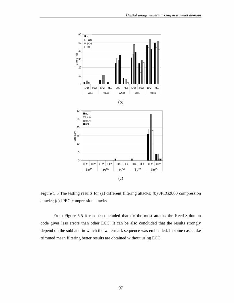
Digital image watermarking in wavelet domain
97
0
10
20
30
40
50
60
LH2 HL2 LH2 HL2 LH2 HL2 LH2 HL2 LH2 HL2
wc50 wc40 wc30 wc20 wc10
Err
ors
(%)
noHamBCHRS
(b)
0
5
10
15
20
25
30
LH2 HL2 LH2 HL2 LH2 HL2 LH2 HL2 LH2 HL2
jpg50 jpg30 jpg30 jpg25 jpg10
Err
ors
(%)
noHamBCHRS
(c)
Figure 5.5 The testing results for (a) different filtering attacks; (b) JPEG2000 compression
attacks; (c) JPEG compression attacks.
From Figure 5.5 it can be concluded that for the most attacks the Reed-Solomon
code gives less errors than other ECC. It can be also concluded that the results strongly
depend on the subband in which the watermark sequence was embedded. In some cases like
trimmed mean filtering better results are obtained without using ECC.

Digital image watermarking in wavelet domain
98
5.5.4 Impact of different Reed-Solomon codes
In [46] the importance of the use of ECC and the different lengths of codewords are
investigated. By this the (15,7), (15,9), (31,11), (31,15) and (31,19) Reed-Solomon codes
are investigated. According to the designation the different message lengths were 360, 300,
465, 310 and 310 bits, respectively. To investigate and evaluate the influence of these five
Reed- Solomon codes the encoded watermark sequences were embedded into several test
images using the DWT based watermarking method described in Section 5.5.1. It was
concluded in [46] after testing the robustness that the (15,7) and (31,11) Reed-Solomon
codes are the most effective codes for image watermarking.
5.5.5 Improvement of the algorithm
The robustness of the proposed algorithm can be increased by combining it with the
image registration technique described in Section 4.1. The scale invariant feature points can
be used as reference locations for calculation of the positions of modified coefficients in the
subbands. In this way the robustness against cropping attack or affine attacks that also
include cropping can be increased.
5.6 Proposed blind watermarking algorithm (B-T02)
In this Section a new blind watermarking algorithm will be proposed. In the algorithm the
original image is decomposed into })4,3,2{(, ∈ll levels of decomposition using the “Haar”
wavelet filters. The watermark is a bipolar pseudorandom sequence )(,),1( Lww oo … , where
L is the length of the sequence. This sequence is encoded with (15,7) Reed-Solomon error
correction code in order to improve the robustness. The new sequence is further divided into
two equal sequences and each sequence (with length 2/L ) is embedded into subbands lLH
and })4,3,2{(,HL ∈ll of the DWT decomposition. The main improvement of this algorithm
comparing with the previous one is that the modified DWT coefficient depends additionally
Digital image watermarking in wavelet domain
99
on the mean value of all DTW coefficients selected for watermark embedding. In this way
the stronger watermark is embedded into the image and it is possible to perform the blind
watermark detection. This will be discussed in the Section 5.6.2 and experimentally
confirmed in the Section 5.6.3.
In order to increase the robustness to cropping attacks, a new position vector of the
selected DWT coefficients for embedding is calculated relative to the location of the feature
points in the subband. This points will be denoted as reference locations and they are
selected as the first three feature points with the largest characteristic scales, extracted with
SIFT detector. In the Appendix A (see Tables A.1-A.3.) it is shown that in a case of
filtering, compression, and image noise attacks it was possible to extract at least 7 feature
points with the largest characteristic scale that correspond to the points on the original
image. The non-corresponding points in our comparison had a smaller characteristic scale
then the point with the maximal scale. The watermark embedding is performed in the central
part of the image. In that way that the image cropping with the certain percentage of the
image size will have no influence on watermark detection. Now the embedding procedure
will be described in details.
5.6.1 Embedding procedure
The embedding procedure is performed in the following steps:
1. Select the central part of the image for watermark embedding (denoted as image cI ).
2. Decompose the image cI into })4,3,2{(, ∈ll levels of DWT decomposition using
the “Haar” wavelet filters.
3. Select subbands lLH and })4,3,2{(,HL ∈ll for embedding.
4. Generate a pseudorandom bipolar signal ow of length L .
5. Encode the watermark sequence with the (15,7) Reed-Solomon error correction code
to obtain the encoded sequence rsw with length rsL .
6. Divide a new sequence rsw into the two sequences 1w and 2w with lengths 1L and
2L , respectively ( 1L and 2L should be approximately 2/rsL ).

Digital image watermarking in wavelet domain
100
7. Select 1L largest coefficients l
fLH from the subband lLH and 2L largest
coefficients l
fHL from the subband lHL .
8. Calculate the variable l
thLH and l
thHL as mean values of the coefficients l
fLH and
lfHL :
)mean( LHLH llfth = (5.13.a)
)mean( HLHL ll
fth = (5.13.b)
9. Embed sequence 1w in subband lLH and sequence 2w in subband lHL according to
the following formula:
)(),(),(),(' 1LHLHLHLH kwalfanmfthnmfnmfllll
⋅⋅++= , 1,,1 Lk …= (5.14.a)
)(),(),(),(' 2HLHLHLHL kwalfanmfthnmfnmfllll
⋅⋅++= , 2,,1 Lk …= (5.14.b)
where ),(LH nmfl
is selected largest coefficient- and ),('LH nmfl
is modified
coefficient at the position ),( nm in subband matrix lLH ; ),(HL nmfl
is selected
largest coefficient- and ),('HL nmfl
is modified coefficient at the position ),( nm in
subband matrix lHL ; alfa is a strength parameter.
10. Select 3 feature points with the largest characteristic scale, extracted with SIFT
detector. In our investigation we have selected only the 3 feature points as a minimal
number of feature points that surely survive the different filtering and compression
operations. It is of course possible to select more then 3 feature point to compute the
redundant position vector, if the memory resources allowed it.
11. Calculate the position of the reference locations in the subbands. For this calculation
the position of the selected feature point will be used. If the position of the feature
point is ),( 21 xx on original image, the location of this reference location in the
DWT subband will be calculated as )2/int( 1l
p xm = and )2/int( 2l
p xn = . This
simple computation is possible while we are using the “Haar” wavelet filter.
Digital image watermarking in wavelet domain
101
12. The new position vector of the selected coefficients in the subband calculate relative
to the position of the reference locations in the subband.
13. Repeat step 11 three times in order to get a redundant position vector.
14. Keep this vector as a secret key.
15. Apply the IDWT transform and add the watermarked part of the image cwI to the
non-watermarked image part ( cII − ).
5.6.2 Detection procedure
An important feature of the algorithm presented is that for the purpose of the
watermark detection the reference image is not needed. The detection procedure is based on
the correlation between the original watermark and the extracted watermark. If the
correlation coefficient is greater than a threshold, the watermark was detected in the image.
The threshold depends on the probability of false positive. A false positive or false detection
occurs when the detector incorrectly concludes that an unwatermarked image contains a
given watermark. The probability of false positive is obtained by applying the detection
procedure to the unwatermarked image.
The detection procedure is described through the following steps:
1. Decompose the central part of the received image crI into the })4,3,2{(, ∈ll levels
of DWT decomposition using the “Haar” wavelet filters.
2. Extract the feature points with SIFT detector and select first three points with the
largest characteristic scale.
3. Calculate the positions of the feature points in the subbands.
4. According to the calculated positions select the coefficients from the subband
matrices lLH and lHL , l
fLH and l
fHL , respectively.
5. Calculate the mean value of the coefficients l
fLH and l
fHL , which will be used as a
thresholds:
)mean( LHLH llfth = (5.15.a)
Digital image watermarking in wavelet domain
102
)mean( HLHL llfth = (5.15.b)
6. If the selected coefficient from lLH or lHL is greater that the threshold then:
;1
;1),(
1
1LHLH
−=
=>
e
e
welse
wthenthnmfifll (5.16.a)
;1
;1),(
2
2HLHL
−=
=>
e
e
welse
wthenthnmfifll (5.16.b)
7. Make a new extracted array rsew by gathering the sequences ew1 and ew2 .
8. The extracted watermark ew will be obtained by applying the Reed-Solomon ECC
decoding on the extracted array rsew .
9. If the correlation coefficient between the extracted watermark and original
watermark is greater then a threshold thr then the watermark was detected.
thrww eo >),corr( (5.17)
where thr represents a threshold depending on the false-positive probability. The
probability of false positive is obtained by applying the detection procedure to the
unwatermarked image I :
}{ maxFA TTPP >= (5.18)
Here T is the correlation coefficient between the extracted watermark and original
watermark. maxT is the maximal value of the correlation coefficient between the
extracted watermark from the unwatermarked image and original watermark. In our
case:
maxTthr = (5.19)

Digital image watermarking in wavelet domain
103
5.6.3 Algorithm B-T02 Testing
In this Section the results of the blind watermarking algorithm testing are presented.
In the testing the pseudorandom bipolar watermark sequence ow of 80 bits is used. After
encoding this sequence with the (15,7) Reed-Solomon ECC, the new sequence rsw contains
180 bits. The sequence rsw is divided into two sequences 1w and 2w , each having length of
90 bits. The algorithm is tested using the same standard 512 x 512 images (barbara, boats,
cameraman, couple, einstein, elaine, f16, goldhill, house and lena image). The original
image is decomposed in })4,3,2{(, ∈ll levels of decomposition using “Haar” wavelet
filters. The watermark embedding is performed according to the algorithm described in
Section 5.6.1. The strength parameter alfa is set to 0.4 as trade off between the visibility
and robustness requirements.
(a)
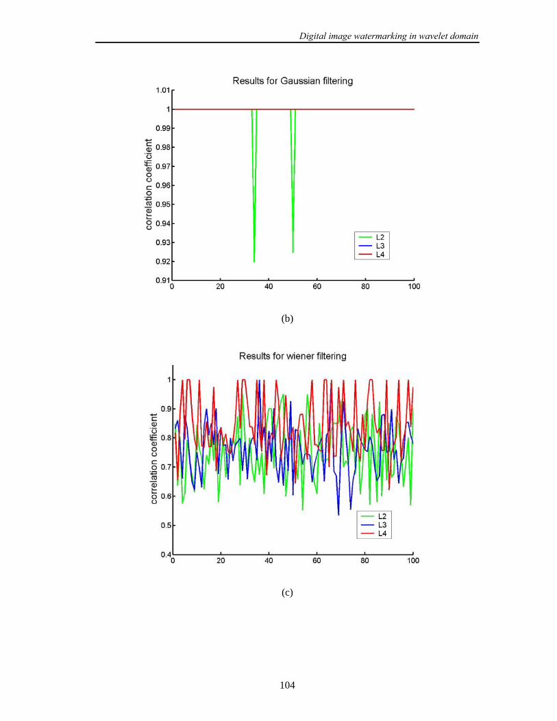
Digital image watermarking in wavelet domain
104
(b)
(c)

Digital image watermarking in wavelet domain
105
(d)
(e)
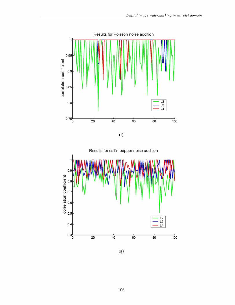
Digital image watermarking in wavelet domain
106
(f)
(g)

Digital image watermarking in wavelet domain
107
(h)
(i)

Digital image watermarking in wavelet domain
108
(j)
(k)

Digital image watermarking in wavelet domain
109
(l)
Figure 5.6: The results of our watermarking algorithm for following attacks: (a) median
filtering; (b) gaussian filtering (c) wiener filtering (d) trimmed mean filtering; (e)
sharpening; (f) Poisson noise addition; (g) salt’n pepper noise addition (h) watermark
extraction from the original image; (i) JPEG2000 compression with 0,4 bit rate; (j)
JPEG2000 compression with 0,5 bit rate; (k) JPEG compression with quality factor 40; (l)
JPEG compression with quality factor 40. The results of correlation are presented for the
watermark embedding into the level 2 (L2), level three (L3) and level four (L4) of DWT
decomposition. The method was tested for 100 different random watermark sequences
embedded in the Barbara image.
The robustness of the algorithm is tested separately for the watermark sequence
embedded in the second, third and fourth level of the wavelet decomposition, respectively.
In order to investigate the influence of different watermark sequences on the robustness the
embedding/detection algorithm has been applied on 100 different watermark sequences for
Barbara image. The watermark embedded in Barbara image was less robust on attacks then
watermark embedded in other test images. The same attacks were performed as described in
Section 5.5.3: med- median filtering with 3x3 window size; gaus- gaussian filtering with
Digital image watermarking in wavelet domain
110
5x5 window size; wien- wiener filtering with 5x5 window size; trim- trimmed mean
filtering with 7x7 window size; sh- sharpening with 3x3 high pass filter; JPEG
compressions with quality factors of 50 and 40 (jpg50, jpg40) and JPEG2000 compressions
with bitrates 0.5 and 0.4 (wc50, wc40). In Figure 5.6 the results of testing are overviewed
presented.
For median filtering attacks (see Figure 5.6.a) the watermark was extracted from
levels L3 and L4. For the level L2 the detection was not successful. Gaussian filtering attack
(see Figure 5.6.b) has almost no influence on the watermark sequence. Also from the level
L2 the watermark sequence was correctly extracted. For wiener filtering attack (see Figure
5.6.c) it was difficult to conclude which level has better performance than others. The
watermark was detected in all levels of decomposition. Trimmed mean filtering has similar
influence on robustness as median filtering (see Figure 5.6.d). Only sequences that were
embedded in the levels L3 and L4 were robust on this attack. The results for sharpening
attack (see Figure 5.6.e) shows that the better robustness was obtained if the watermark was
embedded in the level L3. In a case of noise addition (Poisson (Figure 5.6.f) and salt’n
pepper (Figure 5.6.e)) the watermark was detected in all levels. If the watermark extraction
procedure if performed on original image which does not contain the watermark the
presence of the watermark cannot be confirmed. The highest absolute value of correlation
coefficient was around 0.3. For wc40 attacks the best results are obtained for the level L4.
From the Figure 5.6.i it can be observed that watermark was also extracted from the level
L3. Weaker results are obtained for L2 level. Similar level comparison applies to wc50
attack (see Figure 5.6.j). Only in this case watermark was detected in the level L2. JPEG
compressions with quality factors 40 and 50 have no influence on the watermark embedded
in the levels L3 and L4. High values of correlation coefficient are obtained in level L2, too.
After all these experiment it can be concluded that the best trade off between the
visibility and robustness is achieved if the watermark is embedded in the level L3.
Figure 5.7.a presents the watermarked Barbara image. The watermark was embedded
in the level L3 of wavelet decomposition. In Figure 5.7.b the difference image between the
original and watermarked image is given.
In the next test example in all testing images the same watermark sequence was
embedded in the third level of DWT decomposition. The PSNR values are calculated, as
well as the correlation coefficient between the original and extracted watermark sequence.
In Table 5.2 the obtained results are presented.

Digital image watermarking in wavelet domain
111
(a) (b)
Figure 5.7: (a) watermarked Barbara image; (b) difference image.
Table5. 2: The results
barb boats cam couple Einstein elaine f16 goldhill house Lena
PSNR(db) 44.46 42.7 38.7 43.1 41.33 40.7 40.7 43.91 41.49 40.18
original 0.1076 0.0852 0.1097 0.0772 0.0772 0.0463 0.0852 0.0463 0.0149 0.0463
pois 0.86 1 1 1 1 1 1 1 1 1
salt 1 1 0.9 0.97 0.82 0.83 1 1 1 0.9
gaus 1 1 1 1 1 1 1 1 1 1
med 0.95 1 0.58 1 0.51 1 1 1 0.7 1
trim 1 1 0.63 1 0.58 1 1 1 0.85 1
win 0.85 1 1 0.88 0.79 1 1 1 0.95 1
sh 0.69 0.75 0.7 0.64 0.53 0.74 0.9 0.68 0.73 0.69
wc50 1 1 1 1 1 1 1 1 1 1
wc40 0.86 1 1 1 1 0.92 1 1 1 1
jpg50 1 1 1 1 1 1 1 1 1 1
jpg40 1 1 1 1 1 1 1 1 1 1

Digital image watermarking in wavelet domain
112
From the Table 5.2 it can be concluded that the watermark sequence was detected
after all attacks. The smallest value of correlation coefficient was 0.51. In a case of
watermark extraction from the unwatermarked image (original image) the correlation
coefficient was less then 0.1. It can be concluded that the watermark does not exist in
unwatermarked image.
5.6.4 Robustness on geometrical attacks
The robustness on geometrical attacks is improved by using the syhhronisation
technique described in Section 4.3. The embedding procedure consists of the embedding the
synchronization signal and watermark embedding. Firstly the synchronization signal is
embedded in the original image according to the algorithm from the Section 4.3. Next, the
watermark embedding procedure from Section 5.6.1 is performed. If the affine geometrical
attacks occur which consists of scaling, rotation, cropping or combination of them, the
template extraction algorithm is firstly performed. Then according to the equations (4.35-
4.38) the parameters of rotation and scaling are computed. After that the image is inverse
affine transformed and proceeded to the watermark detector.
In our experiments the same geometrical attacks are performed on the test images
that we have used in our previous experiments: rotations with different angles (rot1- 5º,
rot2- 15º, rot3- 30º), scaling transform with different scaling operations (sc1- 70%, sc2-
90%, sc3- 130) or combined geometric attacks (rs1- rotation of 5º, scaling 130%; rs2-
rotation of 15º, scaling 90%; rs3- rotation of 10º, scaling 150%); image cropping with
different cropping percentage (cr1- 5%, cr2- 10 %, cr3- 15 %, cr4- 20 %).
Based on experiments carried out it can be concluded that the synchronization
technique improves the robustness. The watermark was detected after all tested geometrical
attacks.
Digital image watermarking in wavelet domain
113
5.7 Chapter Summary
In this Chapter firstly the Discrete Wavelet Transform is presented. Then the
important properties of the Wavelet transform, which are used for watermarking, are
outlined. Next, the HVS perceptual model based on DWT is described. The classification of
the existing watermarking algorithms based on DWT is briefly overviewed.
The first watermarking algorithm developed and presented in this thesis is essentially
a classical non-blind additive watermarking algorithm in wavelet domain. Using this
algorithm the impact of different error correction codes on the watermark robustness was
investigated. From this point of view, it is shown that the Read-Solomon error correction
code delivers the best results. Further, it is tested which subband of DWT decomposition
shows the best performances for watermark embedding. The robustness of the watermark
was tested on different filtering and compression attacks. It was concluded that the best
results are obtained if the watermark is embedded in the subbands 2LH and 2HL . The
robustness on geometric attacks of this algorithm is additionally improved by using the
image registration technique from the Section 4.1.
The second watermarking algorithm developed in the wavelet domain belongs to a
class of blind additive algorithms. The watermark sequence is encoded with Read-Solomon
error correction code. The watermark was embedded in the LH and HL subbands of
second, third and fourth levels of the DWT decomposition. The best results were obtained
for the watermark embedded in the LH and HL subbands of third level of decomposition.
The robustness of this algorithm on geometrical attacks is additionally improved by using
the proposed synchronization technique from the Section 4.3. In both algorithms the scale
invariant feature points are used as reference locations for the embedding of watermark
pattern.
In the next Chapter the complex wavelets will be introduced as an extension to the
standard wavelet transform. The advantages of the CWT over standard DWT will be
outlined. Then the watermarking algorithms based on the CWT will be considered in more
detail.
Digital image watermarking in complex wavelet domain
114
Chapter 6
Digital image watermarking in complex
wavelet domain
The complex wavelet transform (CWT) is a complex-valued extension to the
standard discrete wavelet transform (DWT). The complex wavelets have not been widely
used in the watermarking, although they have several desirable features, which can be
applied for watermarking. Chapter 6 gives an overview of watermarking algorithms in
Complex wavelet domain. In Section 6.2 the Complex Wavelet Transform (CWT) will be
briefly described. The literature survey of existing watermarking algorithms is given in
Section 6.3. In Section 6.4 the proposed watermark embedding algorithm is described and
tested in Section 6.5.
6.1 Introduction
The complex wavelet transform of a signal uses two separate trees of real DWT
filters that operate in parallel to generate the real and imaginary parts of a complex filter.
That means that the number of coefficients at the output of the Complex wavelet transform
is doubled comparing with the number of DWT coefficients. The redundancy of the CWT is
then 2:1 for one dimensional signal and 4:1 for two-dimensional signal. This redundancy
introduced by the CWT transform itself has an influence on the design of watermarking
algorithm. Typically a standard transform watermarking algorithm is based on the addition
of a pseudorandom sequence to the host image coefficients in one of the transformation
domains like DCT, DFT, DWT, etc. A watermarked image is obtained by taking the inverse

Digital image watermarking in complex wavelet domain
115
transform. In watermark extraction procedure the CWT transformation is applied on the
watermarked image in order to extract the watermark sequence from the transformation
coefficients. In absence of attacks it is expected that the extracted watermark is the same as
the embedded watermark. Using the CWT transformation this is not the case. Due to the
redundancy of 4:1 a certain part of pseudorandom sequence will be lost. Actually a standard
watermarking algorithm developed for other transform domains like DWT, DCT, DFT, etc.,
cannot be directly implemented in CWT domain. This can be also concluded from the
survey of the existing watermarking algorithms in open literature, which will be given in
Section 6.3.
6.2 Complex wavelet transform and its properties
Wavelet techniques are successfully applied to various problems in signal and image
processing. However, the major problem of the commonly decimated discrete wavelet
transform is its lack of shift invariance, what means that small shifts in the input signal can
cause major variations in the distribution of energy between wavelet transform coefficients
at different scales. This problem is caused by aliasing due to the subsampling at each
wavelet level [101].
The second disadvantage of the DWT is its poor directional selectivity for diagonal
features. The 2D-DWT decompose image in horizontal (0°), vertical (90°) and diagonal
(±45°) directions, HL, LH, HH band respectively. The DWT cannot distinguish between the
two opposing diagonal directions (±45°).
Due to difficulty in designing the complex filters satisfying the perfect
reconstruction (PR) properties, the Complex Wavelets Transform (CWT) has not been used
widely in image processing. The dual-tree complex wavelet transform (DT-CWT) [126] is
relatively recent enhancement to the discrete wavelet transform (DWT) with the following
main properties:
- nearly shift-invariance
- directional selectivity in two and higher dimensions
- Perfect reconstruction using short linear-phase filters
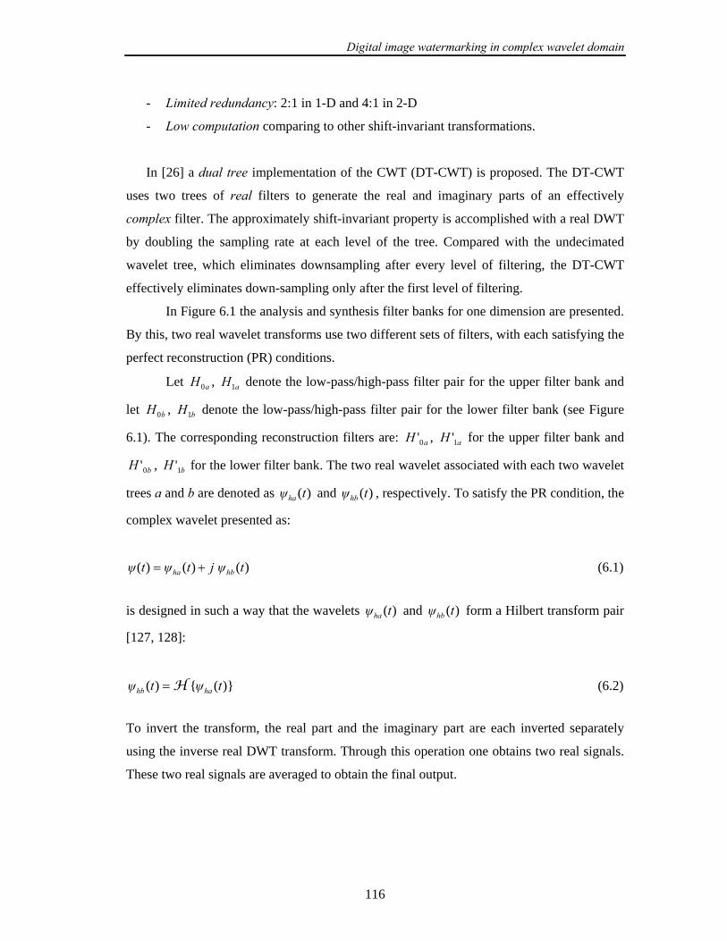
Digital image watermarking in complex wavelet domain
116
- Limited redundancy: 2:1 in 1-D and 4:1 in 2-D
- Low computation comparing to other shift-invariant transformations.
In [26] a dual tree implementation of the CWT (DT-CWT) is proposed. The DT-CWT
uses two trees of real filters to generate the real and imaginary parts of an effectively
complex filter. The approximately shift-invariant property is accomplished with a real DWT
by doubling the sampling rate at each level of the tree. Compared with the undecimated
wavelet tree, which eliminates downsampling after every level of filtering, the DT-CWT
effectively eliminates down-sampling only after the first level of filtering.
In Figure 6.1 the analysis and synthesis filter banks for one dimension are presented.
By this, two real wavelet transforms use two different sets of filters, with each satisfying the
perfect reconstruction (PR) conditions.
Let aH0 , aH1 denote the low-pass/high-pass filter pair for the upper filter bank and
let bH0 , bH1 denote the low-pass/high-pass filter pair for the lower filter bank (see Figure
6.1). The corresponding reconstruction filters are: aH 0' , aH 1' for the upper filter bank and
bH 0' , bH 1' for the lower filter bank. The two real wavelet associated with each two wavelet
trees a and b are denoted as )(tψha and )(tψhb , respectively. To satisfy the PR condition, the
complex wavelet presented as:
)()()( tψjtψtψ hbha += (6.1)
is designed in such a way that the wavelets )(tψha and )(tψhb form a Hilbert transform pair
[127, 128]:
)}({)( tψtψ hahb H= (6.2)
To invert the transform, the real part and the imaginary part are each inverted separately
using the inverse real DWT transform. Through this operation one obtains two real signals.
These two real signals are averaged to obtain the final output.
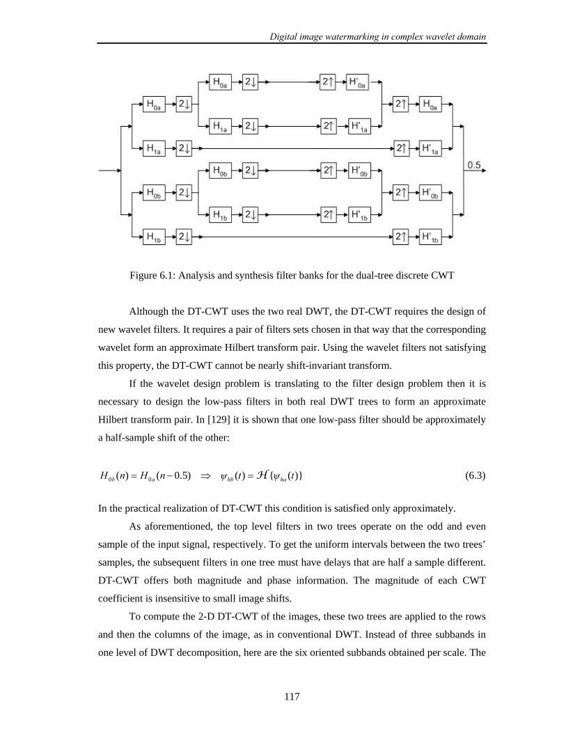
Digital image watermarking in complex wavelet domain
117
Figure 6.1: Analysis and synthesis filter banks for the dual-tree discrete CWT
Although the DT-CWT uses the two real DWT, the DT-CWT requires the design of
new wavelet filters. It requires a pair of filters sets chosen in that way that the corresponding
wavelet form an approximate Hilbert transform pair. Using the wavelet filters not satisfying
this property, the DT-CWT cannot be nearly shift-invariant transform.
If the wavelet design problem is translating to the filter design problem then it is
necessary to design the low-pass filters in both real DWT trees to form an approximate
Hilbert transform pair. In [129] it is shown that one low-pass filter should be approximately
a half-sample shift of the other:
)}({)()5.0()( 00 tψtψnHnH hahbab H=⇒−= (6.3)
In the practical realization of DT-CWT this condition is satisfied only approximately.
As aforementioned, the top level filters in two trees operate on the odd and even
sample of the input signal, respectively. To get the uniform intervals between the two trees’
samples, the subsequent filters in one tree must have delays that are half a sample different.
DT-CWT offers both magnitude and phase information. The magnitude of each CWT
coefficient is insensitive to small image shifts.
To compute the 2-D DT-CWT of the images, these two trees are applied to the rows
and then the columns of the image, as in conventional DWT. Instead of three subbands in
one level of DWT decomposition, here are the six oriented subbands obtained per scale. The

Digital image watermarking in complex wavelet domain
118
orientations of the subbands are: ±15, ±45 and ±75 degrees. The six wavelets associated
with the real 2D dual-tree DWT are illustrated in the Figure 6.2 as gray scale images. Note
that each of the six wavelets is oriented in a distinct direction.
+75 +45 +15 -75 -45 -15
Figure 6.2: 2-D filter impulse responses of DT-CWT.
One example of oriented subbands of CWT decomposition of House image is
presented on Figure 6.3.
-75 LP LP +75
-45 -15 +15 +45
Figure 6.3: Example of the CWT decomposition of House image. Only magnitudes of two
levels of decomposition are shown. The orientation of the corresponding filter is shown in
corner of each subband. The contrast of the images has been enhanced for illustration
purpose. LP corresponds to lowpass CWT coefficients.
The DT-CWT is inherently sensitive to rotation, but the sum of the energies of
coefficients across all 6 directional subbands is reasonably invariant to rotation. In [130] the
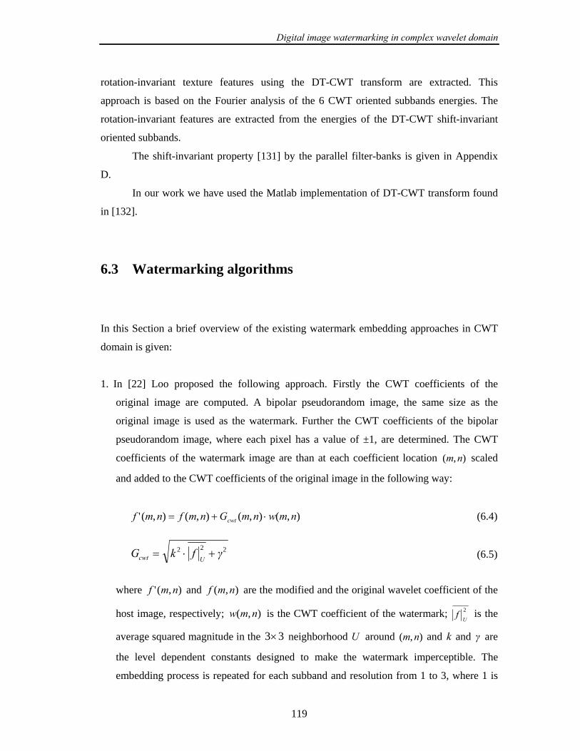
Digital image watermarking in complex wavelet domain
119
rotation-invariant texture features using the DT-CWT transform are extracted. This
approach is based on the Fourier analysis of the 6 CWT oriented subbands energies. The
rotation-invariant features are extracted from the energies of the DT-CWT shift-invariant
oriented subbands.
The shift-invariant property [131] by the parallel filter-banks is given in Appendix
D.
In our work we have used the Matlab implementation of DT-CWT transform found
in [132].
6.3 Watermarking algorithms
In this Section a brief overview of the existing watermark embedding approaches in CWT
domain is given:
1. In [22] Loo proposed the following approach. Firstly the CWT coefficients of the
original image are computed. A bipolar pseudorandom image, the same size as the
original image is used as the watermark. Further the CWT coefficients of the bipolar
pseudorandom image, where each pixel has a value of ±1, are determined. The CWT
coefficients of the watermark image are than at each coefficient location ),( nm scaled
and added to the CWT coefficients of the original image in the following way:
),(),(),(),(' nmwnmGnmfnmf cwt ⋅+= (6.4)
222 γfkGUcwt +⋅= (6.5)
where ),(' nmf and ),( nmf are the modified and the original wavelet coefficient of the
host image, respectively; ),( nmw is the CWT coefficient of the watermark; 2
Uf is the
average squared magnitude in the 33× neighborhood U around ),( nm and k and γ are
the level dependent constants designed to make the watermark imperceptible. The
embedding process is repeated for each subband and resolution from 1 to 3, where 1 is

Digital image watermarking in complex wavelet domain
120
the finest resolution. The watermark detection is based on the correlation between the
watermark coefficients w and the CWT coefficients of the received image. The
watermark capacity was calculated but the robustness of the presented algorithm on the
watermarking attacks was not investigated.
2. In [23] a similar approach to [22] is presented. By this at levels 2 and 3 only the
embedding procedure is applied. Before embedding the binary watermark data is divided
into 6 bit symbols, and each symbol is encoded with (32,6) error correction Hadamard
code. The payload is the concatenation of all such codewords. As in the previous
algorithm, the robustness on watermarking attacks was not investigated.
3. In [133] the embedding in the spatial domain is performed in the following way. A
random image of ±1 of the same size as the host image is generated and the CWT
coefficients of both images are computed. The scaling factors (the visual mask) are
computed from the host image’s CWT coefficients using equation (6.5), independently
for each subband. The random image coefficients are modulated by the payload. The
modulated coefficients are scaled and then inverse transformed to form a watermark. At
the end in order to obtain the marked image, the watermark is added to the host image in
the spatial domain. The robustness of this algorithm was tested for three standard images
(Lena, baboon, Pills) on compression attacks (JPEG, JPEG2000), Additive White
Gaussian Noise (AWGN), mean, median and denoising attacks. The presence of the
watermark was detected after all tested attacks.
4. In [133] the approach is based on the Chen quantisation based watermarking algorithm
[134]. Here the spread transform, which is a combination of spread spectrum technique
and quantisation based watermarking, is used. The algorithm has the following steps.
The host image is divided into 3232× blocks and the payload is divided into equal-
sized portions, with each portion being embedded into separate block. A pseudorandom
vector of ±1 (the same size as one block) is generated for each bit of the payload to be
embedded. The forward CWT of this vector is computed, and scaled according to local
image activity. The scaled coefficients of this vector are frequency partitioned into 3
vectors, with each one reconstructed back into the spatial domain using only one level of
CWT coefficients. From this instant the watermarking process takes place in the spatial
domain, the CWT domain is only used for adapting the random vector to the image.
5. In [135] an incremental watermarking technique is proposed. A grey-scale image is
firstly decomposed into the 1-level DWT and then the low-frequency part LL1 is

Digital image watermarking in complex wavelet domain
121
embedded into the image, as a watermark. The original image is decomposed into the 3-
level DT-CWT decomposition. The watermark is added to the phase component of the
DT-CWT coefficients. At the extracting step, the algorithm incrementally compares the
extracted watermark with the original one using correlation from lowest to highest level.
The proposed technique through performance evaluation shows that it was more robust
in geometric distortions than a conventional CWT-based watermarking. The algorithm
was also robust on noise addition and image blurring attacks.
From this brief overview of the existing watermarking algorithms it can be
concluded that the watermarking in the CWT domain is still an open problem. In most of
this approaches the robustness of the algorithms on different distortions was not enough
tested. In the next Session we will propose a new watermarking algorithm and show that
this algorithm outperforms the existing watermarking algorithms based on CWT.
6.4 The new watermarking algorithm based on DT - CWT
(C - T03)
A new watermarking algorithm based on CWT will be described in the following
Sections. The robustness of the algorithm on geometrical attacks will be improved using the
image registration technique from the Section 4.1.
6.4.1 Embedding procedure
In this Section a watermarking algorithm based on DT-CWT is presented [42, 43,
47]. The algorithm is performed in spatial domain. By this, the watermark embedding is
based on the spread spectrum additive technique. In Figure 6.4 the embedding scheme is
presented. The original image I is firstly CWT transformed into four levels of CWT
decomposition. Each level of decomposition with its coefficients 321 ,, fff and 4f is
separately selected and inverse CWT transformed. The approximation level with
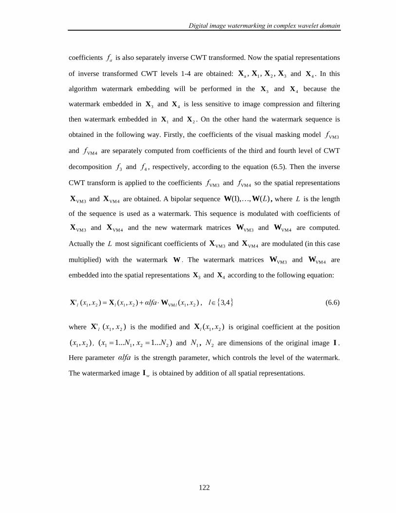
Digital image watermarking in complex wavelet domain
122
coefficients af is also separately inverse CWT transformed. Now the spatial representations
of inverse transformed CWT levels 1-4 are obtained: 321a ,,, XXXX and 4X . In this
algorithm watermark embedding will be performed in the 3X and 4X because the
watermark embedded in 3X and 4X is less sensitive to image compression and filtering
then watermark embedded in 1X and 2X . On the other hand the watermark sequence is
obtained in the following way. Firstly, the coefficients of the visual masking model 3VMf
and 4VMf are separately computed from coefficients of the third and fourth level of CWT
decomposition 3f and 4f , respectively, according to the equation (6.5). Then the inverse
CWT transform is applied to the coefficients 3VMf and 4VMf so the spatial representations
3VMX and 4VMX are obtained. A bipolar sequence )(,),1( LWW … , where L is the length
of the sequence is used as a watermark. This sequence is modulated with coefficients of
3VMX and 4VMX and the new watermark matrices 3VMW and 4VMW are computed.
Actually the L most significant coefficients of 3VMX and 4VMX are modulated (in this case
multiplied) with the watermark W . The watermark matrices 3VMW and 4VMW are
embedded into the spatial representations 3X and 4X according to the following equation:
),(),(),(' 21VM2121 xxαlfaxxxx lll WXX ⋅+= , { }4,3∈l (6.6)
where ),(' 21 xxlX is the modified and ),( 21 xxlX is original coefficient at the position
),( 21 xx , )...1,...1( 2211 NxNx == and 1N , 2N are dimensions of the original image I .
Here parameter αlfa is the strength parameter, which controls the level of the watermark.
The watermarked image wI is obtained by addition of all spatial representations.

Digital image watermarking in complex wavelet domain
123
Figure 6.4: Block scheme of the embedding procedure.
Figure 6.5: Watermarked image wI after attacks.
Due to intentional or unintentional alterations of the watermark image (attacks) (see Figure
6.5) in the extraction procedure it will be spoken about received image rI instead of
watermarked image wI .
In order to improve the robustness on geometrical attacks the positions of the
modified coefficients in 3X and 4X are calculated relative to the three feature points with
the largest characteristic scale extracted with SIFT detector.
The watermark embedding procedure can be described using the following steps:
Digital image watermarking in complex wavelet domain
124
1. Decompose the image into the four-level CWT. Every level of CWT decomposition
is separately ICWT reconstructed to form the spatial representations: 1X , 2X , 3X ,
4X for detail levels and aX for approximation level.
2. Calculate the visual masks 3VMX and 4VMX for the representations 3X and 4X .
3. Modulate the L largest coefficients from 3VMX and 4VMX with a bipolar watermark
sequence W in order to obtain the watermark matrices 3VMW and 4VMW . The
position of the significant coefficients will be used in extraction procedure as a
secret key.
4. Embed the watermark into the spatial representations 3X and 4X according to the
equation (6.6).
5. The watermarked image wI is obtained by addition of watermarked spatial
representations 3'X and 4'X to aX , 1X and 2X :
'4
'321a XXXXXI ++++=w (6.7)
6. Apply the SIFT to the original image I and find the first three points with the largest
characteristic scale.
7. Calculate the redundant position vector relative to the selected feature points.

Digital image watermarking in complex wavelet domain
125
6.4.2 Detection procedure
Detection procedure consists of two stages. If the watermarked image is altered with
an affine geometrical distortion, firstly the parameters of affine transformation will be
computed using the original and received image (see algorithm from the Section 4.1). After
that, the image is inverted and the watermark detection procedure is performed. In the case
of cropping attacks or non-geometrical attacks, the watermark detection procedure can be
directly implemented to the received image. In the watermark detection procedure (Figure
6.6) the classical non-blind technique is implemented. The received, possibly altered image
after attacks rI is CWT decomposed into four levels of decomposition. The coefficients of
the third and the fourth level of decomposition rf3 , rf4 are separated and inverse CWT
transformed ( r3X , r4X ). The same procedure is repeated for the original image I . The
spatial representations 3X and r3X , 4X and r4X are now subtracted and the watermark
sequences 3eW and 4eW are extracted.
Figure 6.6: Block scheme of the extraction procedure
Digital image watermarking in complex wavelet domain
126
The detection procedure is given in the following steps:
1. Apply the SIFT detector to the image rI and find the first three points with the
largest characteristic scale.
2. Calculate the position vector of the modified coefficients relative to the selected
feature points.
3. Apply the four-level CWT and ICWT to the image rI and I in order to obtain the
spatial representations r3X and r4X , 3X and 4X , respectively.
4. Extract the watermark using the following formula:
alfaxxxxk lrlrl /)),(),(()( 2121 XXW −= , { }4,3∈l (6.8)
))(sign()(e kk rll WW = , { }4,3∈l (6.9)
5. Compare the extracted watermark leW with original watermark W by applying the
correlation:
)(),corr( e FAl Pη≥WW (6.10)
where )( FAPη represents a threshold depending on the false-positive probability FAP .
The probability of false positive will be obtained by running the detector on the
unwatermarked image I . The maximal value of the correlation coefficient ( maxT )
between the extracted watermark from the unwatermarked image and original
watermark will be used as a threshold:
max)( TPη FA = (6.11)
6.4.3 Testing results (C-T03)
For the testing purpose 10 tested standard images with the size of 512 x 512 are
used: barbara, boats, cameraman, couple, einstein, elaine, f16, goldhill, house and lena

Digital image watermarking in complex wavelet domain
127
image. The watermark sequence is obtained in the following way. The message
“Watermark” is firstly converted into the ASCII code. Every letter is converted into an eight
bit sequence according to the ASCII rule. By using 8 bits per character for 9 watermark
characters a 72-bits watermark message is obtained. The watermark message consists of
zeros and ones and for the embedding purpose the sequence is bipolar encoded in that way
that 0 is replaced with –1 and 1 with 1.
Before embedding, the watermark message is encoded with a Reed-Solomon (15,7)
Error Correction Code (ECC). The Reed-Solomon code uses a codeword length of 15 bits
and a message length of 7 bits. The length of the encoded watermark message is 180 bits.
The watermark is embedded according to the embedding rule from Section 6.3.1 (see
equation 6.6). The values of constants k and γ used for evaluation of the visual model are
listed in Table 6.1, where 0k is set to 0.9 [133]. We have used the same value of the
constants k and γ for third and fourth level of CWT decomposition.
In Table 6.2 the Peak Signal to Noise Ratio (PSNR) values are calculated for every
used image and respectively presented. The strength parameter αlfa is selected for every
image differently in such a way that the computed PSNR value is grater than 44 dB. By
visually analyzing Lena image (see Figure 6.7), it can be concluded that the watermark is
invisibly embedded. The same was valid for other analyzed images. In Figure 6.8 the Lena
image is decomposed into the spatial representations aX , 1X , 2X , 3X , 4X .
Table 6.1: Table of constants used in CWT visual model [133].
Level 1
±75 ±15
Level 1
±45
Level 2
±75 ±15
Level 2
±45
Level 3
±75 ±15
Level 3
±45
k 1· 0k 0.55· 0k 1.05· 0k 1.05· 0k 1.10· 0k 1.35· 0k
γ 1.5 3.1 0.75 0.9 1.05 1.0
Table 6.2. PSNR values (dB) of the analyzed images:
barb boats cam couple einstein elaine f16 goldhill house lena
PSNR(db) 47.56 47.24 44.2 48.44 47.59 48.9 46.3 48.2 47.87 47.9
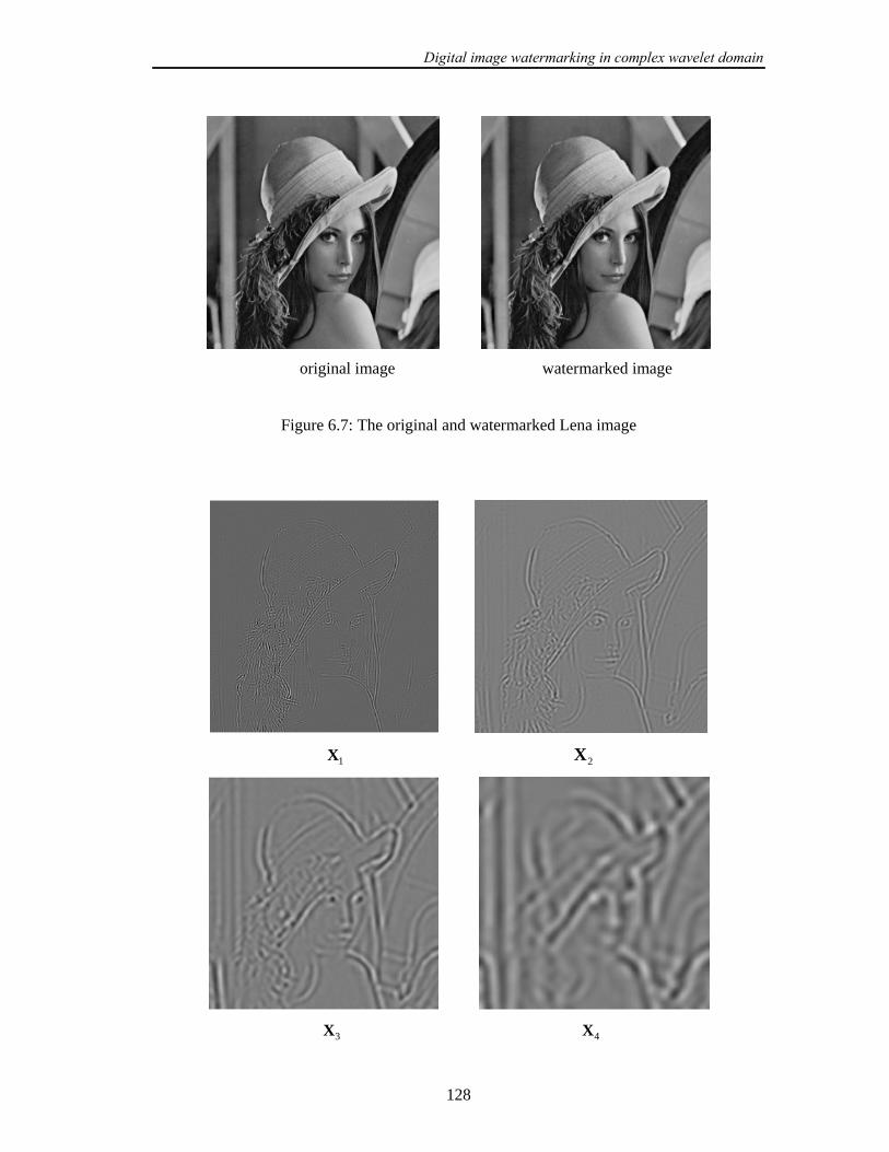
Digital image watermarking in complex wavelet domain
128
original image watermarked image
Figure 6.7: The original and watermarked Lena image
1X 2X
3X 4X

Digital image watermarking in complex wavelet domain
129
aX
Figure 6.8: Decompositions of Lena image into the spatial representations of approximation
CWT level aX and detail levels ( 1X , 2X , 3X , 4X ) are shown. The contrast of the images
has been enhanced for illustration purpose.
The robustness of the algorithm is tested separately for the watermark sequence
embedded in 3X and 4X representations. The same attacks were performed as in Section
5.6.3: med- median filtering; gaus- gaussian filtering; wien- wiener filtering; trim- trimmed
mean filtering; sh- sharpening; JPEG compressions with quality factors of 50 and 40 (jpg50,
jpg40) and JPEG2000 compressions with bitrates 0.5 and 0.4 (wc50, wc40). After
watermark extraction procedure the watermark sequence is decoded with (15,7) Reed-
Solomon ECC. This sequence is now compared wit the original watermark sequence by
applying the correlation. As a correlation threshold the false-positive probability is
computed by running the detector on the unwatermarked image. In our experiments the
highest value of the false-positive probability for both 3X and 4X representations was 0.2.
We used this value as the detection threshold. The results are presented in the Table 6.3.
It can be observed from the table that the watermark was detected in both 3X and
4X . In all cases the watermark was detected from 4X . The watermark sequence embedded
3X was robust on all attacks except on median, trimmed mean and wiener filtering. The
results for these attacks were different for different images. Generally it cannot be

Digital image watermarking in complex wavelet domain
130
concluded that for median, trimmed mean and wiener filtering attacks the watermark was
detected from the spatial representation 3X .
Comparing the robustness of the proposed algorithm with other algorithms [22, 23,
132, 134], this algorithm shows better performances. It was robust on wider class of filtering
attacks, which include wiener, trimmed mean filtering and sharpening. Table 6.4 gives an
overview of the comparison of the existing methods. “1” in the Table denotes that the
algorithm was robust on specific attack while 0 denotes that algorithm was not robust on
specific attack. “n.i.” denotes that the robustness was not investigated.
Comparing the proposed algorithm in the CWT domain with the DWT algorithms
proposed in the Chapter 5, it can not be concluded that it outperforms the DWT algorithms.
Although the CWT has several important improvements with regard to the DWT, the
development of the watermarking techniques in the CWT domain, which can fully explore
the possible advantages of the CWT, is still an open research problem.
6.4.4 Robustness on geometrical attacks
In order to improve the robustness on cropping attack the watermark was embedded
only in the central part of the image. In that way, if the image is cropped till the certain
percentage of the image size, the watermark will be still present in the image. The position
vector of modified coefficients from the 3X and 4X is calculated relative to three scale
invariant feature points with the largest characteristic scale. In a case of affine geometrical
attack the robustness of the proposed technique can be increased by combining the
technique with our image registration technique from Section 4.1. When the parameters of
affine transformations are determined, the inverse transformation can be applied to the
received image and then the watermark extraction procedure can be performed.
The same geometrical attacks are performed on the test images that we have used in
our previous experiments: rotations with different angles (rot1- 5º, rot2- 15º, rot3- 30º),
scaling transform with different scaling operations (sc1- 70%, sc2- 90%, sc3- 130) or
combined geometric attacks (rs1- rotation of 5º, scaling 130%; rs2- rotation of 15º, scaling
90%; rs3- rotation of 10º, scaling 150%); image cropping with different cropping percentage

Digital image watermarking in complex wavelet domain
131
(cr1- 5%, cr2- 10 %, cr3- 15 %, cr4- 20 %). The watermark was detected after all tested
geometrical attacks in both 3X and 4X spatial representations.
Table 6.3: The results for non-geometrical attacks.
barb boats cam couple einstein elaine f16 goldhill house Lena
X3 0.94 1 0.68 1 1 0.92 1 0.84 1 0.91 pois
X4 1 0.97 1 1 1 1 1 1 1 1
X3 0.8 0.97 0.68 0.88 0.81 0.58 0.78 0.4 0.78 0.8 salt
X4 0.91 0.75 0.78 1 1 0.89 0.92 0.94 0.86 1
X3 0.52 1 0.57 0.86 0.94 0.8 0.89 0.69 0.86 0.83 gaus
X4 1 1 1 1 1 1 0.97 1 1 1
X3 0.15 0.91 0.56 0.36 0.97 0.5 0.23 0.14 0.16 0.19 med
X4 1 1 1 0.95 0.976 1 1 0.95 1 0.92
X3 0.21 0.7 0.51 0.01 0.62 0.45 0.02 0.41 0.08 0.15 trim
X4 0.92 1 1 0.95 1 1 0.94 0.94 1 0.97
X3 0.29 0.86 0.04 0.19 0.84 0.47 0.25 0.16 0.07 0.33 win
X4 0.6 0.5 0.75 1 1 0.89 0.43 0.95 0.97 0.78
X3 1 1 0.69 1 1 1 1 0.97 1 1 sh
X4 1 1 0.97 1 1 1 1 1 1 1
X3 0.51 1 0.91 1 1 0.89 1 0.8 1 1 wc50
X4 1 1 1 0.94 1 1 1 1 1 1
X3 0.5 1 0.87 0.92 1 0.89 1 0.64 1 1 wc40
X4 0.91 0.97 1 0.95 1 1 1 1 11 1
X3 0.92 1 0.79 1 1 1 1 0.78 1 1 jpg50
X4 1 1 1 1 1 1 0.95 1 1 1
X3 0.97 1 0.76 1 1 0.89 1 0.75 0.94 1 jpg40
X4 1 0.97 1 1 1 1 1 1 1 0.92

Digital image watermarking in complex wavelet domain
132
Table 6.4: Comparison of the existing watermarking methods based on DT-CWT.
gaus med trim win sh jpg wc
Loo in [135] 1 1 n.i. n.i. n.i. 1 1
Lee in [137] 1 n.i. n.i. n.i. n.i. n.i. n.i.
C-T03 1 1 1 1 1 1 1
6.5 Chapter Summary
In this Chapter the drawbacks of the real wavelet transform are reviewed and a dual
tree implementation of the complex wavelet transform is introduced. It is outlined how the
CWT overcomes the problems with the conventional real wavelet transform. The overview
of the existing watermarking algorithms based on CWT is then given. Next, a new
watermarking algorithm, based on the CWT, is proposed. This algorithm requires the
original image for watermark extraction. In order to improve the robustness, the watermark
is encoded with the Read-Solomon error correction code. The scale invariant feature points
extracted with SIFT detector are used as reference locations for the embedding and
extraction of the watermark. The robustness of the algorithm is tested for different filtering
(median, gaussian, wiener, trimmed mean filtering; and sharpening) and compression
attacks (JPEG and JPEG2000). The proposed watermarking algorithm shows the robustness
on all tested attacks. The robustness of this algorithm on geometrical attacks is further
improved by using the image registration technique from the Chapter 4.1. The proposed
algorithm is compared with other existing watermarking algorithms based on CWT and it
showed better performances.
Conclusion and Future Research Directions
133
Chapter 7
Conclusions and Future Research
Directions
7.1 Thesis Overview
The work described in this thesis is concerned with the design of robust digital image
watermarking algorithms for copyright protection. Various types and application of
watermarks were introduced and an overview of existing watermarking algorithms and
attacks are given.
In the field of watermarking, the feature points can be used as the reference locations
for the both the watermark embedding and detection processes. The feature points are
detected with feature point detectors and these detectors should extract the feature points
that are robust on various distortions (compression, filtering, geometric distortions, etc.).
A new class of scale invariant feature point detectors, which is robust to
transformations like rotation, scale and translation, is introduced and later applied for
watermarking. A comparison between two scale-invariant feature point detectors:
- SIFT feature point detector and
- Harris-Affine feature point detector,
showed that the SIFT feature point detector gives more robust feature points for the most of
the geometrical distortions (e.g. rotation, scaling or combinations of them).

Conclusion and Future Research Directions
134
In the case of filtering and compressions (JPEG and JPEG 2000), both detectors
showed excellent performances. However, in experiments presented, only the feature points
with the largest characteristic scale were observed.
The resistance of watermarking schemes against geometrical distortions is one of the
still opened and challenging problems in the field of watermarking. One possibility to
recover the watermark synchronization is to implement the image registration technique
before the watermark detection procedure. An image registration technique, based on
establishing point-by-point correspondence between the original image and image possibly
altered by unknown geometrical transformation (received image) is demonstrated. The
feature points are extracted with the SIFT detector, where as the SIFT descriptors were
calculated for every feature point. The correspondences between the points were established
by measuring the correlation coefficient between the SIFT descriptors. When the
correspondence between two images is determined, the parameters of the undergone
geometrical transformation are estimated and an inverse geometrical transformation is
calculated and applied to the received image. This technique effectively estimates the
parameters of undergone affine transformation.
Another possibility to recover the watermark synchronization is to implement the
synchronization technique proposed in Section 4.3. One important feature of this technique
is that it does not require the presence of original, or watermarked image. This technique
combines the template based and content based approach. The main idea of this technique is
to extract the robust feature points with SIFT detector and to embed in the neighborhood of
every feature point two information, which can be later used to detect the parameters of
undergone geometrical transformations. These two information are embedded robustly
using DFT and they represent information about the reference angle and the information
about the characteristic scale of the feature point. When the affine transformation, consisted
of image rotation, scaling, cropping or combination of them, occurs, it is enough correctly to
detect at least from one feature point neighborhood these two information. After that, the
parameters of rotation and scaling can be easily calculated. This was demonstrated in
experiments presented, and it is shown that compressions (JPEG and JPEG2000) have no
influence on the extraction of these two information, as well.
The first watermarking algorithm developed and presented in this thesis is essentially
a classical non-blind additive watermarking algorithm in wavelet domain, just like many of
the existing algorithms. Using this algorithm the impact of different error correction codes

Conclusion and Future Research Directions
135
on the watermark robustness was investigated. From this point of view, it is shown that the
Read-Solomon error correction code delivers the best results. The same watermark is
embedded in all detail subbands of a two-level DWT. Further, it is tested which subband of
DWT decomposition shows the best performances for watermark embedding. The
robustness of the watermark was tested on different filtering and compression attacks. It was
concluded that the best results are obtained if the watermark is embedded in the subbands
2LH and 2HL . The robustness on geometric attacks of this algorithm is additionally
improved by using the aforementioned image registration technique.
The second watermarking algorithm developed in the wavelet domain belongs to a
class of blind additive algorithms. The watermark embedding is performed in the central
part of the image. In this way the cropping of the certain percentage of the image size (in
our case, we set to 25 %) has no influence on the watermark detection. The watermark
sequence is encoded with Read-Solomon error correction code and embedded in the largest
coefficients of the LH and HL DWT subbands. In order to increase the robustness on
cropping attacks, a new position vector of the modified DWT coefficients is calculated
redundantly and relative to the location of the feature points in the subband. In a classical
additive approach, the modified DWT coefficient depends on the original DWT coefficient
and the watermark. Here this coefficient depends additionally on the mean value of all DTW
coefficients selected for watermark embedding. In this way the stronger watermark was
embedded into the image which enables later blind watermark detection. In the thesis the
robustness of different watermarks on attacks is tested. The watermark was embedded in the
LH and HL subbands of second, third and fourth levels of the DWT decomposition. The
best results were obtained for the watermark embedded in the LH and HL subbands of
third level of decomposition. The robustness of this algorithm on geometrical attacks is
additionally improved by using the aforementioned proposed synchronization technique.
The next watermarking algorithm developed is based on the CWT. It is an additive
algorithm and it requires the original image for watermark extraction. Here the complex
wavelets were introduced as an alternative to conventional real wavelets. They overcome
two main drawbacks of real wavelets: a) lack of shift invariance and b) directional
selectivity. However, since the CWT is a redundant transform a different watermarking
approach is here applied. Firstly, the fourth level of the CWT decomposition is performed
and then every level of decomposition is separately inverse transformed to form the spatial
representations. In order to improve the robustness, the watermark is encoded with the

Conclusion and Future Research Directions
136
Read-Solomon error correction code. The watermark is embedded in the spatial
representation of the third and fourth level of decomposition. The scale invariant feature
points extracted with SIFT detector are used as reference locations for the embedding of the
watermark. The robustness of the algorithm is tested for different filtering (median,
gaussian, wiener, trimmed mean filtering; and sharpening) and compression attacks (JPEG
and JPEG2000). In all cases the watermark was detected from the spatial representation of
the fourth level of the CWT decomposition. The watermark sequence embedded in the
spatial representation of the third level of CWT decomposition was robust on all attacks
except on median, trimmed mean and wiener filtering. The robustness of this algorithm on
geometrical attacks is further improved by using the aforementioned image registration
technique. The proposed algorithm showed better performances compared to other existing
watermarking algorithms based on the CWT.
7.2 Future Research Directions
In this Section few unresolved issues are summarized, and some possible research
directions are addressed.
In Chapter 4 the novel synchronization technique is proposed, which does not
require the presence of the original image. This technique calculates the parameters of affine
transformation, which include rotation, scaling or combination of them. In the case of an
affine transformation, when the scale change is not necessarily the same in every direction,
automatically selected characteristic scales do not reflect the real transformation of a feature
point. The future work will be related to the development of the technique, which can
recover the other parameters of affine transformation like shearing parameter, or scale
parameter, which is not the same in every direction.
In Chapter 5, using the non-blind additive algorithm developed in wavelet domain,
the impact of different error correction codes was investigated. The use of error correction
codes for digital watermarking is still an open problem. It requires design of codes, which
are able to take into account many different kinds of attacks. In [136] the enhanced
robustness in image watermarking is achieved using block turbo codes. Implementation of

Conclusion and Future Research Directions
137
convolution codes, or turbo codes in watermarking algorithms presented in this thesis,
should be a part of the future research.
Both watermarking algorithms developed in the wavelet domain and presented in
Chapter 5 do not use the perceptual models. The watermarks should be perceptually similar
to the cover image if they have to be resistant to copy attacks, or other estimation based
attacks. The implementation of different perceptual models should be done as an extension
to the proposed watermarking algorithms.
In Chapter 6 the watermarking algorithm in CWT domain is developed. Although
the CWT has several important improvements with regard to the DWT, there is still a need
to study deeply the watermark embedding techniques in the CWT domain, which can fully
explore the possible advantages of the CWT.

Appendices
138
Appendices
In this Chapter the results from Section 3.3, as well as the following two important
transformations used in this Thesis:
- Radon Transform and
- Fourier-Mellin Transform.
are presented.
In addition, the main features of the shift-invariance of the Complex Wavelets
Transform are addressed. Finally, all test images used in this thesis are overviewed
presented.

Appendices
139
Appendix A Comparaison of Feature Points Detectors: Results Table A.1: The number of corresponding feature points between the distorted image and
original test image. The points are extracted with SIFT detector (column SF) and Harris-
Affine detector (column HA). jpg40 jpg50 wc40 wc50 med. gaus wien. trim. salt poiss
n SF HA SF HA SF HA SF HA SF HA SF HA SF HA SF HA SF HA SF HA
10 10 9 10 9 9 8 10 8 8 8 10 10 10 10 10 9 9 8 8 10
20 19 18 20 19 16 17 17 16 17 14 20 19 19 19 20 17 17 14 16 20
barbara
30 25 25 29 28 24 23 25 24 27 22 28 29 27 29 29 26 25 21 26 28
10 9 9 9 10 8 9 10 9 9 8 9 10 9 10 9 8 7 8 8 9
20 17 18 18 18 17 18 18 18 17 14 19 20 19 19 18 17 16 15 17 17
boats
30 27 27 28 27 24 28 28 28 26 21 29 30 27 28 27 25 22 22 26 24
10 8 10 9 9 8 9 8 9 9 6 8 10 8 10 8 9 8 8 9 9
20 18 19 18 19 17 18 17 18 19 12 18 20 17 19 17 17 16 15 19 18
camera-
man 30 25 28 28 27 23 28 24 28 27 17 22 29 26 27 25 22 22 22 26 23
10 8 10 9 10 8 10 8 10 8 9 10 10 9 10 8 9 7 10 9 8
20 17 18 17 20 14 19 15 18 16 17 19 20 17 19 16 17 14 15 16 16
couple
30 25 24 24 29 20 26 18 25 21 23 27 30 25 26 24 24 20 22 23 25
10 9 10 10 9 9 10 10 9 10 9 10 10 10 9 9 9 8 7 9 9
20 18 19 18 18 16 19 18 18 19 16 19 20 19 18 18 18 15 15 17 17
einstein
30 28 27 27 28 25 29 27 27 27 23 27 30 28 28 26 27 20 19 24 24
10 9 10 7 10 7 9 8 9 9 8 9 10 10 10 9 10 9 8 10 9
20 17 18 16 19 17 17 17 17 17 16 18 20 18 20 17 19 17 16 18 18
elaine
30 25 26 25 27 26 25 26 25 26 21 27 30 27 30 26 29 25 22 27 26
10 10 10 9 9 10 9 10 10 8 10 10 9 10 9 10 9 7 9 10 9
20 19 19 10 18 18 17 20 20 17 18 20 17 20 18 18 17 16 15 18 18
f16
30 29 29 29 28 28 27 29 30 26 26 29 26 30 28 29 26 22 24 27 27
10 10 10 10 10 9 10 8 10 7 8 10 10 9 10 8 10 8 8 7 10
20 19 20 20 19 18 19 17 19 16 17 19 20 18 20 18 20 16 16 16 19
goldhill
30 27 29 27 28 25 26 24 29 24 26 27 30 28 28 27 28 20 23 24 28
10 9 10 9 10 6 10 6 9 8 8 8 10 8 9 9 2 8 10 9 8
20 11 18 12 19 12 18 10 18 11 17 11 19 13 18 11 4 13 18 17 16
house
30 15 27 17 24 17 27 15 27 17 24 17 29 16 28 15 6 18 25 22 25
10 10 10 10 10 9 10 8 10 9 10 10 10 10 10 9 10 9 10 9 10
20 19 19 19 19 19 18 17 18 18 19 20 20 19 20 19 19 17 16 19 20
lena
30 28 29 29 29 27 28 25 28 24 25 30 30 28 28 28 29 24 24 27 29

Appendices
140
Table A.2: The number of corresponding feature points between the distorted image and
original test image. The points are extracted with SIFT detector (column SF) and Harris-
Affine detector (column HA).
rot1 rot2 rot3 rot4 sc1 sc1 sc3 sc4
n SF HA SF HA SF HA SF HA SF HA SF HA SF HA SF HA
10 5 5 5 1 4 1 3 2 6 2 7 3 8 1 4 3
20 10 9 8 4 7 3 10 4 14 4 16 8 18 2 14 7
barbara
30 20 13 17 8 15 6 15 7 22 6 23 8 25 3 22 9
10 4 2 4 2 4 3 4 1 7 1 8 2 7 4 4 5
20 10 4 8 5 8 6 9 4 14 2 16 4 14 6 12 7
boats
30 17 6 16 9 15 8 15 7 22 5 24 5 23 7 19 10
10 5 2 3 2 4 1 6 1 8 1 7 5 8 1 7 4
20 12 5 12 2 11 4 14 2 14 4 13 5 16 3 14 7
cameraman
30 19 7 18 7 18 10 20 6 22 5 10 9 24 5 24 10
10 5 2 6 2 6 1 6 1 5 1 7 4 6 1 2 1
20 10 7 11 4 10 4 12 1 11 3 13 6 14 3 9 4
couple
30 16 8 16 8 17 7 15 2 19 5 20 11 20 4 14 5
10 6 2 6 1 5 1 7 1 6 2 9 2 7 4 5 4
20 14 7 15 3 15 2 15 5 16 5 17 5 15 8 12 5
einstein
30 21 13 22 5 21 3 22 8 25 11 23 9 24 14 20 10
10 4 2 4 1 4 1 3 1 3 1 5 3 6 1 5 2
20 9 5 8 3 7 2 7 2 11 2 15 7 14 2 12 7
elaine
30 15 8 15 4 13 5 13 3 19 3 22 9 22 7 21 9
10 5 6 3 3 2 1 4 2 7 3 8 3 7 1 6 1
20 13 8 10 5 9 3 10 4 14 5 16 5 14 3 13 4
f16
30 21 12 16 9 15 5 20 5 19 7 25 8 25 4 19 9
10 5 5 4 4 5 1 5 1 5 3 6 3 6 1 5 2
20 11 6 10 8 14 5 8 6 12 5 16 5 14 3 13 4
goldhill
30 17 12 19 10 20 6 15 10 19 7 22 8 21 7 19 7
10 7 3 6 1 7 1 5 1 7 3 8 1 4 1 3 2
20 12 5 13 4 13 4 10 3 14 8 14 2 11 1 6 6
house
30 19 10 19 7 19 8 15 4 18 9 20 3 18 2 12 10
10 6 3 5 4 3 3 4 1 6 3 7 2 6 4 4 3
20 12 7 11 8 10 6 9 4 13 8 15 6 12 10 13 8
lena
30 21 15 19 16 16 10 17 10 22 16 22 12 18 16 18 16

Appendices
141
Table A.3 The number of corresponding feature points between the distorted image and
original test image. The points are extracted with SIFT detector (column SF) and Harris-
Affine detector (column HA).
cr1 cr2 cr3 cr4 cr5 rs1 rs2 rs3 rs4
SF HA SF HA SF HA SF HA SF HA SF HA SF HA SF HA SF HA
10 9 8 8 8 7 7 6 6 4 2 4 1 5 2 2 2 3 1
20 19 15 16 14 15 11 12 10 14 6 13 2 12 4 7 5 8 3
barbara
30 27 23 22 20 20 17 17 15 22 11 19 3 15 4 12 8 14 4
10 6 10 5 9 5 8 5 8 5 6 3 2 3 3 2 5 2 1
20 13 19 12 18 11 18 11 17 10 14 8 4 7 4 7 7 4 2
boats
30 23 28 20 25 18 24 17 23 16 20 14 7 12 6 14 8 10 3
10 9 10 7 7 7 7 7 7 7 7 5 1 4 1 5 1 3 1
20 19 20 16 16 16 15 16 15 15 15 13 6 10 4 11 3 9 3
cameraman
30 25 28 23 24 22 23 22 23 19 23 19 7 17 5 20 5 10 6
10 9 9 5 7 3 5 3 5 3 5 4 1 3 3 2 2 2 2
20 16 16 11 15 9 11 8 11 8 10 11 4 7 5 7 4 5 3
couple
30 24 26 16 24 13 20 13 20 12 18 11 6 11 8 12 6 10 6
10 9 9 9 8 7 8 7 8 7 8 8 2 6 3 5 3 4 1
20 18 20 18 17 15 17 15 17 14 15 16 5 13 4 12 5 11 2
einstein
30 24 30 23 26 20 26 20 26 17 24 22 7 19 8 17 10 17 4
10 8 10 6 7 5 4 3 3 3 3 5 1 3 1 4 2 2 2
20 16 19 14 16 12 12 9 11 8 10 12 1 8 5 10 5 8 4
elaine
30 25 28 22 25 20 21 17 20 16 17 20 5 12 7 15 6 12 6
10 10 8 6 8 5 6 3 4 3 3 5 1 2 1 2 3 1 2
20 18 16 12 16 11 13 9 11 9 10 9 2 5 1 7 6 4 2
f16
30 28 28 20 26 18 23 15 21 15 20 15 3 13 2 14 10 8 4
10 9 10 8 8 7 6 6 6 6 6 5 3 3 1 4 5 2 4
20 19 19 15 17 12 14 12 14 11 13 13 3 11 4 13 8 5 4
goldhill
30 27 28 20 26 16 23 16 22 15 21 20 5 15 7 17 11 10 6
10 7 8 3 6 3 5 2 5 2 5 3 1 6 1 2 2 3 1
20 18 16 12 13 10 12 8 11 8 10 7 1 8 1 4 5 7 1
house
30 24 24 17 21 14 20 12 17 12 15 12 3 12 3 9 8 10 2
10 9 9 6 9 6 8 6 8 5 7 4 4 5 6 3 3 5 3
20 16 19 15 17 12 15 12 14 11 13 9 11 8 9 9 9 7 5
lena
30 23 29 21 27 20 25 20 24 19 22 16 17 13 13 16 11 12 10

Appendices
142
Appendix B Radon Transform
The Radon Transform represents an image as a collection of projections along
various directions. A projection of a two-dimensional function ),( 21 xxf is a line integral in
a certain direction. For example, the line integral of ),( 21 xxf in the vertical direction is the
projection of ),( 21 xxf onto the 1x -axis; the line integral in the horizontal direction is the
projection of ),( 21 xxf onto the 2x -axis. Projections can be computed along any angle θ . In
general, the Radon Transform of ),( 21 xxf is the line integral of the following expression:
')cos'sin',sin'cos'()'( 221211 dxθxθxθxθxfxRθ +−= ∫∞
∞−
(B.1)
where
⎥⎦
⎤⎢⎣
⎡⎥⎦
⎤⎢⎣
⎡−
=⎥⎦
⎤⎢⎣
⎡
2
1
2
1
cossinsincos
''
xx
θθθθ
xx
(B.2)

Appendices
143
Appendix C Fourier-Mellin Transform
The basic translation invariants described in Section 4.3.1 may be converted to
rotation and scale invariants using the log-polar map.
Consider a point 221 ),( ℜ∈xx and define:
θex μ cos1 = (C.1)
θex μ sin2 = (C.2)
where ℜ∈μ and πθ 20 << . One can see that for every point ),( 21 xx there is a point
),( θμ that uniquely corresponds to it. The new coordinate system has the following
properties:
Scaling is converted to a translation.
),log(),( 21 θρμρxρx +↔ (C.3)
Rotation is converted to a translation.
),())cos()sin(),sin()cos(( 2121 δθμδxδxδxδx +↔+− (C.4)
At this stage one can implement a rotation and scale invariant by applying a
translation invariant in the log-polar coordinate system. Taking the Fourier transform of a
log-polar map is equivalent to computing the Fourier-Mellin transform:
[ ] θddμθωμωiθeθefωωFπ
μμM ∫ ∫
∞
∞−
+=2
02121 )(exp)sin,cos(),( (C.5)
The magnitude of the Fourier-Mellin transform is rotation and scale invariant.

Appendices
144
Appendix D Shift Invariance by Parallel Filter Banks
The orthogonal two-channel DWT filter banks with analysis low-pass filter given by the z-
transform )(0 zH , analysis highpass filter )(1 zH and with synthesis filters )(0 zG and )(1 zG
is shown in Figure D.1 [131].
Figure D.1: DWT filter bank.
For an input signal )(zX , the analysis part of the filter bank followed by upsampling
produces the low-pass (equation (D.1)) and the high-pass (equation (D.2)) coefficients
)}()()()({21)( 00
21 zHzXzHzXzC −−+= (D.1)
)}()()()({21)( 11
21 zHzXzHzXzD −−+= (D.2)
respectively, and decomposes the input signal into a low frequency part )(1 zXl and a high
frequency part )(1 zX h . The output signal )(zY is the sum of these two components:
)()()( 11 zXzXzY hl += (D.3)
where
Appendices
145
)}()()()()()({21)()()( 00000
211 zGzHzXzGzHzXzGzCzXl −−+== (D.4)
)}()()()()()({21)()()( 11111
211 zGzHzXzGzHzXzGzDzX h −−+== (D.5)
This decomposition is not shift invariant due to the terms in )( zX − of (equation (D.4)) and
(equation (D.5)), respectively, which are introduced by the downsampling operators.
If the input signal is shifted, for example )(1 zXz− , the application of the filter bank results
in the decomposition
)(~)(~)( 111 zXzXzXz hl +=− (D.6)
where
)}()()()()({21)( 0
10
121 zHzXzzHzXzzC −−−+= −− (D.7)
and
)}()()()()()({21)(~
000011 zGzHzXzGzHzXzzXl −−−= − (D.8)
and similarly for the high-pass part. From this calculation it can be seen that the shift
dependence is caused by the terms containing )( zX − , the aliasing terms. This filter bank is
shift invariant with respect to a double shift since 1)1( 2 =− and
))()(()( 1122 zXzXzzXz hl += −− (D.9)
One possibility to obtain a shift invariant decomposition can be achieved by
applying an additional filter bank with shifted analysis filters )(01 zHz− , )(1
1 zHz− and

Appendices
146
synthesis filters )(0 zzG , )(1 zzG and subsequently averaging the lowpass and the highpass
channels of both filter banks (Figure D.2).
Figure D.2: One level of complex dual tree filter bank.
If we denote the first filter bank by index a and the second one by index b then this
procedure implies the following decomposition:
)()()( 11 zXzXzX hl += (D.10)
where for the lowpass channels of tree a and tree b we have
)()()(21
)]}()()()()[(
)]()()()()[({41
)}()]())(()()([
)()]()()()({[41
)}()()()({21)(
00
0000
0000
001
01
000
021
0211
zGzHzX
zGzHzGzHzX
zGzHzGzHzX
zzGzHzzXzHzzX
zGzHzXzHzX
zGzCzGzCzX bbaal
=
−−−−+
++=
−−−++
+−−+=
+=
−−
(D.11)

Appendices
147
and similarly for the high-pass part. The aliasing term containing )( zX − in )(1 zXl has
vanished and the decomposition becomes indeed shift invariant.

Appendices
148
Appendix E Test Images
All test images are grey scale of 512 x512 pixels.
barbara boats couple cameraman
einstein elaine f16 goldhill
house lena

List of Publications
149
List of Publications
[1] N. Terzija, M. Repges, K. Luck, W. Geisselhardt, “Digital Image Watermarking
Using Discrete Wavelet Transform: Performance Comparison of Error Correction
Codes”, published in Proceedings of the Second IASTED International Conference
on Visualization, Imaging and Image Processing, Malaga, Spain, September 2002.
[2] N. Terzija, M. Repges, K. Luck, W. Geisselhardt, “Impact of different Reed-
Solomon codes on digital watermarks based on DWT”, Multimedia and Security
Workshop at ACM Multimedia 2002, Juan-les-Pins, France, December 2002.
[3] N. Terzija, “Digital Image Watermarking in The Wavelet Domain”, Technical
Report, Faculty of Engineering Sciences, Gerhard-Mercator-Universität Duisburg,
December 2002, http://www.fb9dv.uni-duisburg.de/members/ter/trep_1202.pdf
[4] N. Terzija, W. Geisselhardt, “Robust Digital Image Watermarking Method Based
On Discrete Fourier Transform”, InProceedings of the 5th IASTED International
Conference on Signal and Image Processing, Honolulu, Hawaii, August 2003.
[5] N. Terzija, W. Geisselhardt, Digital Image Watermarking Using Complex Wavelet
Transform, ACM Multimedia and Security Workshop 2004, Magdeburg, Germany,
September 2004.
[6] N. Terzija, W. Geisselhardt, “Robust Digital Image Watermarking Based on
Complex Wavelet Transform”, In WSEAS Transactions on Communication, Issue
10, Volume 4, pp 1086-1092, October 2005, ISSN 1109-2742.
[7] N. Terzija, W. Geisselhardt, “Robust Digital Image Watermarking Using Feature
Point Detectors”, In Proceedings of the 9th WSEAS International Multiconference
CSCC on Communication, Vouliagmeni Beach, Athens, Greece, July 13-15, 2005.
[8] N. Terzija, W. Geisselhardt, „A Novel synchronisation approach for digital image
watermarking based on scale invariant feature point detector”, IEEE International
Conference on Image Processing, (ICIP 2006), Atlanta, GA, USA, October 8-11
2006.

References
150
References
[1] B. Schneier, Applied cryptography, (2nd Edition), John Wiley, 1996.
[2] I. J. Cox, M. L. Miller, and J. A. Bloom, “Digital Watermarking”, Morgan
Kaufmann, 2001.
[3] R. B. Wolfgang, E. J. Delp, “A Watermark For Digital Images”, IEEE International
Conference on Image Processing (ICIP'96), 1996.
[4] R. B. Wolfgang, E. J. Delp, “A watermarking technique for digital imagery: further
studies”, In International Conference on Imaging, Systems, and Technology, pages
279-287, Las Vegas, NV, USA, 30 June-3 July 1997. IEEE.
[5] A. Z. Tirkel, R. G. Schyndel, C. F. Osborne, “A two dimensional digital watermark“,
Digital Image Computing, Te chnology and Applications, pp. 378-383, Brisbane,
Australia, 1995.
[6] O. Bruyndonckx, J.-J. Quisquater, B. Macq, “Spatial method for copyright labeling
of digital images," in Proc. Workshop on Nonlinear Signal and Image Processing (I.
Pitas, ed.), pp. 456-459, June 1995.
[7] I. Pitas, “A method for signature casting on digital images”," in Proc. IEEE Int.
Conference on Image Processing, vol. 3, pp. 215{218, 1996.
[8] W. Bender, D. Gruhl, and N. Morimoto, “Techniques for data hiding," in Proc.
SPIE, Storage and Retrieval for Image and Video Databases III (W. Niblack and R.
C. Jain, eds.), vol. 2420, pp. 164-173, February 1995.
[9] A. Herrigel, J. J. K. Ó Ruanaidh, H. Petersen, S. Pereira, T. Pun, “Secure copyright
protection techniques for digital images”, In David Aucsmith ed., Information
Hiding, Vol. 1525 of Lecture Notes in Computer Science, pp. 169-190, Springer,
Berlin, 1998. (Second International Workshop IH'98, Portland, OR, USA, April 15-
17, 1998).
[10] S. Pereira, J. J. K. Ó Ruanaidh, F. Deguillaume, G. Csurka, T. Pun, “Template based
recovery of Fourier-based watermarks using log-polar and log-log maps”, In IEEE

References
151
Multimedia Systems 99, International Conference on Multimedia Computing and
Systems, Vol. 1, pp. 870-874, Florence, Italy, 7-11 June 1999.
[11] J. J. K. Ó Ruanaidh, S. Pereira, “A secure robust digital image watermark”, In
Electronic Imaging: Processing, Printing and Publishing in Colour, SPIE
Proceedings, Zürich, Switzerland, May 1998. (SPIE/IST/Europto Symposium on
Advanced Imaging and Network Technologies)
[12] I. J. Cox; J. Kilian, F. T. Leighton, T. Shamoon, “Secure spread spectrum
watermarking for multimedia”, IEEE Transactions on Image Processing, Volume: 6
Issue: 12, Dec. 1997, pp. 1673 –1687.
[13] A. Piva, M. Barni, f. Bartolini, V. Cappellini, “DCT-based watermark recovering
without resorting to the uncorrupted original image”, in Proc. ICIP 97, IEEE Int.
Conf. Image Processing, Santa Barbara, CA, Oct. 1997, pp. 520-527.
[14] F. M. Boland, J. J. K. Ó Ruanaidh, C. Dautzenberg, “Watermarking digital images
for copyright protection”, in Proc. IEE Int. Conf. on Image Processing and its
Applications, Edinburgh, U.K., July 1995, pp. 326-330.
[15] C.-T. Hsu, J.-L. Wu, „Hidden signatures in images“, in Proc. ICIP-96, IEEE Conf.
Image Processing, vol. III, Lausanne, Switzerland, Sept. 16-19, 1996, pp. 223-226.
[16] C. Podilchuk, W. Zeng, „Perceptual watermarking of still images”, in Proc. 1997
IEEE 1st Workshop Multimedia Signal Processing, Princeton, NJ, June 23-25,
1997, pp. 363-368.
[17] X. Xia, C.G. Boncelet and G.R. Arce, Wavelet transform based watermark for
digital images, Optics Express, Vol. 3, No. 12, December 1998.
[18] H.-J. Wang, P.-C. Su, C.-C. J. Kuo, „Wavelet-based digital image watermarking”.
Optics Express, Vol. 3 pp. 497, December 1998.
[19] W. Zhu, Z. Xiong, Y.-Q. Zhang, “Multiresolution watermarking for images and
video: a unified approach”, In Proceedings of the IEEE International Conference on
Image Processing, ICIP '98, Chicago, IL, USA, October 1998.
[20] N. Kaewkamnerd, K.R. Rao, “Multiresolution based image adaptive watermarking
scheme”, in EUSIPCO, Tampere, Finland, Sept. 2000.
[21] D. Kundur, D. Hatzinakos, „Digital watermarking using multiresolution wavelet
decomposition”, In Proceedings of IEEE ICASSP '98, volume 5, pages 2969 - 2972,
Seattle, WA, USA, May 1998.

References
152
[22] P. Loo, N.G. Kingsbury, Digital watermarking with complex wavelets, Proc IEE
Colloquium on Secure Images and Image Authentication, IEE, London, 10 April,
2000.
[23] P Loo, N G Kingsbury, Digital Watermarking using Complex Wavelets, Proc. IEEE
Conf. on Image Processing, Vancouver, September 11-13, 2000, paper 3608.
[24] http://www.jpeg.org
[25] A. N. Skodras, C.A. Christopoulos, T. Ibrahimi, “JPEG2000: the upcoming still
image compression standard” Proc. Of the 11th Portugese conference on pattern
recognition, pp. 359-366, May 2000.
[26] N G Kingsbury, “Image Processing with Complex Wavelets”, Phil. Trans. Royal
Society London A, 357:2543-2560, September 1999.
[27] J. J. K. O. Ruanaidh, T. Pun, “Rotation, scale and translation invariant spread
spectrum digital image watermarking”, Signal Processing 66, pp. 303-318, May
1998.
[28] C. Lin, M. Wu, J. A. Bloom, I. Cox, M. Miller, Y. Lui, “Rotation, scale, and
translation resilient public watermarking for images”, Proceedings of the SPIE,
Security and Watermarking of Multimedia Contents 3971, pp. 90-98, 2000.
[29] C.-Y. Lin, “Public watermarking surviving general scaling and cropping: An
application for print-and-scan process”, Multimedia and Security Workshop at ACM
Multimedia 99, (Orlando, FL, USA), Oct 1999.
[30] M. Kutter, F. Jordan, F. Bossen, “Digital signature of colour images using amplitude
modulation”, in Proc. SPIE Storage and Retrieval for Image and Video Databases,
3022, pp. 518-526, (San Jose, California), 1997.
[31] M. Alghoniemy, A. H. Tewfik, “Progressive quantized projection watermarking
scheme”, Proc. of the 7th ACM International Multimedia Conference , pp. 295-298,
(Orlando, FL), Nov. 1999.
[32] A. Herrigel, J. J. K. O. Ruanaidh, H. Petersen, S. Pereira, T. Pun, “Secure copyright
protection techniques for digital images”, in In David Aucsmith ed., Information
Hiding, L. N. o. C. S. Springer Verlag, ed., 1525, pp. 169-190, (Berlin, 1998.
(Second International Workshop IH'98, Portland, OR, USA, April 15-17, 1998)),
1998.
[33] F. Deguillaume, G. Csurka, J. J. K. O. Ruanaidh, T. Pun, “Robust 3d dft video
watermarking”, Vol. 3657 of SPIE Proceedings, pp. 113-124, Electronic Imaging

References
153
'99: Security and Watermarking of Multimedia Contents, (San Jose CA, USA), 23-
29 January 1999.
[34] S. Pereira and T. Pun, “An iterative template matching algorithm using the chirp-z
transform for digital image watermarking”, in Pattern Recognition, 33, 1, pp.
173.175, January 2000.
[35] M. Kutter, S. K. Bhattacharjee, and T. Ebrahimi, “Toward second generation
watermarking schemes,” in Proc. IEEE Int. Conf. Image Process., vol. 1, 1999, pp.
320–323.
[36] P. Bas, J-M. Chassery, B. Macq, “Geometrically invariant watermarking using
feature points”, IEEE Trans. on Image Processing, Vol. 11 (2002) 1014-1028.
[37] C.W. Tang, H-M. Hang, “A feature-based robust digital image watermarking
scheme”, IEEE Trans. on Signal Processing, Vol. 51 (2003) 950-959.
[38] C. Harris, M. Stephen, “A combined corner and edge detector”, in 4th Alvey Vision
Conf., pages 147-151, 1988.
[39] D. Marr, Vision. San Francisco, CA: Freeman, 1982, pp. 54–61.
[40] K. Mikolajczyk, C. Schmid, “Scale and Affine invariant interest point detectors”, In
International Journal of Computer Vision 1(60): 63-86, 2004.
[41] D. Lowe, “Distinctive image features from scale invariant keypoints”, In
International Journal of Computer Vision 2(60): 91-110, 2004.
[42] N. Terzija, W. Geisselhardt, “Robust Digital Image Watermarking Based on
Complex Wavelet Transform”, In WSEAS Transactions on Communication, Issue
10, Volume 4, pp 1086-1092, October 2005, ISSN 1109-2742.
[43] N. Terzija, W. Geisselhardt, “Robust Digital Image Watermarking Using Feature
Point Detectors”, In Proceedings of the 9th WSEAS International Multiconference
CSCC on Communication, Vouliagmeni Beach, Athens, Greece, July 13-15, 2005.
[44] N. Terzija, W. Geisselhardt, „A Novel synchronisation approach for digital image
watermarking based on scale invariant feature point detector”, IEEE International
Conference on Image Processing, (ICIP 2006), Atlanta, GA, USA, October 8-11
2006.
[45] N. Terzija, M. Repges, K. Luck, W. Geisselhardt, “Digital Image Watermarking
Using Discrete Wavelet Transform: Performance Comparison of Error Correction
Codes”, published in Proceedings of the Second IASTED International Conference
on Visualization, Imaging and Image Processing, Malaga, Spain, September 2002.
References
154
[46] N. Terzija, M. Repges, K. Luck, W. Geisselhardt, “Impact of different Reed-
Solomon codes on digital watermarks based on DWT”, Multimedia and Security
Workshop at ACM Multimedia 2002, Juan-les-Pins, France, December 2002.
[47] N. Terzija, W. Geisselhardt, Digital Image Watermarking Using Complex Wavelet
Transform, ACM Multimedia and Security Workshop 2004, Magdeburg, Germany,
September 2004.
[48] Cox, I. J.; Miller, M. L.; McKellips, A. L.; “Watermarking as communications with
side information”, Proceedings of the IEEE , Volume: 87 Issue: 7 , July 1999, pp.
1127 –1141
[49] M. Costa, “Writing on dirty paper ”, IEEE Transactions on Information Theory,
Volume: 29 Issue: 3 , May 1983, pp. 439 –441.
[50] F. Hartung, B. Girod, “Digital Watermarking of MPEG-2 Coded Video in the
Bitstream domain,”, Proceedings of the IEEE International Conference on
Acoustics, Speech and Signal Processing, Vol. 4, Munich, Germany, Apr. 1997, pp.
2621-2624.
[51] A. Z. Tirkel, C. F. Osborne, R. G. van Schyndel, “Image watermarking- a spread
spectrum application," in Proc. IEEE Int. Symposium on Spread Spectrum
Techniques and Applications, vol. 2, pp. 785-789, 1996
[52] C. Berrou, A. Glavieux, “Near optimum error correcting coding and decoding:
turbo-codes”, IEEE Transactions on Communications , Volume: 44 Issue: 10, Oct.
1996 Page(s): 1261 –1271.
[53] J. J. Eggers, J. K. Su, B. Girod, "Robustness of a Blind Image Watermarking
Scheme," in Proceedings of IEEE International Conference on Image Processing
(ICIP 2000), Vancouver, Canada, September 2000.
[54] S. Katzenbeisser, F.A.P Petitcolas, “Information Hiding Techniques for
Steganography and Digital Watermarking”, Artech House, Boston – London 2000.
[55] A. B. Watson, ”DCT Quantization Matrices Optimized for Individual Images”,
Human Vision, Visual Processing, and Digital Display IV, SPIE-1913:202, 1993.
[56] S. Voloshynovskiy, S. Pereira, V. Iquise, T. Pun, “Attack modelling: Towards a
second generation benchmark”, Signal Processing, 81, 6, pp. 1177-1214, June 2001.
Special Issue: Information Theoretic Issues in Digital Watermarking, 2001. V.
Cappellini, M. Barni, F. Bartolini, Eds.
References
155
[57] Langelaar, R. Langedijk, J. Biemond, “Removing Watermarks by Nonlinear
Filtering”, Proc. European Signal Processing, Rhodes, Greece, Sept. 1998
[58] J. Su, B. Girod, “Power-Spectrum Condition for Energy-Efficient Watermarking”,
ICIP, 1999.
[59] F. A. P. Petitcolas, R. J. Anderson, M. G. Kuhn. “Attacks on copyright marking
systems”, in David Aucsmith (Ed), Information Hiding, Second International
Workshop, IH’98, Portland, Oregon, U.S.A., April 15-17, 1998, Proceedings, LNCS
1525, Springer-Verlag, ISBN 3-540-65386-4, pp. 219-239.
[60] F. A. P. Petitcolas, “Watermarking schemes evaluation“. I.E.E.E. Signal Processing,
vol. 17, no. 5, pp. 58–64, September 2000.
[61] M. Kutter, S. Voloshynovskiy, A. Herrigel, “The watermark Copy Attack”, Security
and Watermarking of Multimedia Contents, II, SPIE-3971: 371-280, 2000.
[62] S. Craver, N. Memon, B. Yeo, and M. Yeung, “Can invisible watermarks resolve
rightful ownerships," in Technical Report RC 20509. 1997, IBM Research Institute.
[63] http://www.cl.cam.ac.uk/~fapp2/watermarking/stirmark/
[64] http://watermarking.unige.ch/Checkmark/
[65] www.certimark.org
[66] H. T. Sencar, N. Memon, “Watermarking and ownership problem: a revisit”, in
Proceedings of the 5th ACM workshop on Digital rights management, Alexandria,
VA, USA, 2005, pp. 93-101.
[67] S. Craver N. Memon B. Yeo and M. Yeung, “Resolving rightful ownership with
invisible watermarking techniques: Limitation, attacks, and implications," IEEE
Journal on Selected Areas in Communications, vol. 16, no. 4, pp.573-586, 1998.
[68] L. Qiao and K. Nahrstedt, “Watermarking methods for mpeg encoded video:
Towards resolving rightful ownership," in Proc. of ICMCS, 1998, vol. 9, pp. 194-
210.
[69] W. Zeng and B. Liu, “On resolving rightful ownerships of digital images by
invisible watermarks," in Proc. of ICIP. 1997, pp. 552-555
[70] A. Adelsbach, B. Ptzmann, and A. R. Sadeghi, “Proving ownership of digital
content," in Proc. of IHW'99, Lecture Notes in Computer Science. 2000, vol. 1768,
pp. 126-141, Springer-Verlag.

References
156
[71] S. Katzenbeisser and H. Veith, “Securing symmetric watermarking schemes against
protocol attacks," in Proc. of SPIE: Security and Watermarking of Multimedia
Contents, 2002, vol. 4675, pp. 260-268.
[72] A. Adelsbach, S. Katzenbeisser, and H. Veith, “Watermarking schemes provably
secure against copy and ambiguity attacks," in Proc. of ACM CCS-10 Workshop on
Digital Rights Management, 2003.
[73] J. P. Antoine, P. Vandergheynst, R. Murenzi, “Two-dimensional directional
wavelets in image processing”, Int. J. Imaging Sys. and Tech., 7:152-165, 1996.
[74] F. Aurenhammer, R. Klein, "Voronoi Diagrams", Ch. 5 in Handbook of
Computational Geometry (Ed. J.-R. Sack and J. Urrutia), Amsterdam, Netherlands:
North-Holland, pp. 201-290, 2000.
[75] M. Alghoniemy, A. H. Tewfik, “Geometric distortion correction through image
normalization,” in Proc. IEEE Int. Conf. Multimedia Expo., vol. 3, 2000, pp. 1291–
1294.
[76] M. Tone, N. Hamada, “Affine Invariant Digital image watermarking using feature
points”, International Workshop on Nonlinear Circuit and Signal Processing,
Hawaii, USA, Mar. 2005.
[77] T. Lindeberg. “Feature detection with automatic scale selection”, International
Journal of Computer Vision, 30(2):79-116, 1998.
[78] K. Mikolajczyk, C. Schmid, ”Indexing based on scale invariant interest points”, In
Proceedings of the 8th International Conference on Computer Vision, Vancouver,
Canada, pages 525-531, 2001.
[79] K. Mikolajczyk, C. Schmid, “A performance evaluation of local descriptors”, In
Proceedings of the Conference on Computer Vision and Pattern Recognition,
Madison, Wisconsin, USA, June 2003.
[80] C. Schmid, R. Mohr, and C. Bauckhage, “Evaluation of interest point detectors”,
International Journal of Computer Vision, 37(2):151-172, 2000.
[81] H.-Y. Lee, I. K. Kang, H.-K. Lee, Y.-H. Suh, “Evaluation of Feature Extracrion
Techniques for Robust Watermarking”, IWDW 2005, LNCS 3710, pp. 418-431,
2005.
[82] http://www.robots.ox.ac.uk/~vgg/research/affine/
[83] J. Lichtenauer, I. Setyawan, T. Kalker, R. Lagendijk, “Exhaustive geometrical
search and false positive watermark detection probability”, in SPIE Electronic

References
157
Imaging 2002, Security and Watermarking of Multimedia Contents V, (Santa Clara),
January 2003.
[84] J. L. T. Kalker, G. Depovere, “Modelling the false-alarm and missed detection rate
for electronic watermarks”, in Workshop on Information Hiding, S. L. N. on
Computer Science, ed., pp. 329-343,(Portland, OR), 15-17 April 1998.
[85] M. L. Miller, J. A. Bloom, “Computing the probability of false watermark
detection”, in Information Hiding, pp. 146-158, 1999.
[86] A. Tefas, I. Pitas, “Multi-bit image watermarking robust to geometric distortions”, in
IEEE-ICIP'2000, (Vancouver, Canada), 2000.
[87] V. Solachidis, I. Pitas, “Circularly symmetric watermark embedding in 2-d dft
domain”, ICASSP'99 6, pp. 3469-3472, (Phoenix, Arizona),15-19 March 1999.
[88] M. Maes, T. Kalker, J. Linnartz, J. Talstra, G. Depovere, J. Haitsma, “Digital
watermarking for dvd video copy protection”, IEEE Signal Processing Magazine
17(5), pp. 47-57, 2000.
[89] D. Delannay and B. Macq, “Generalized 2-d cyclic patterns for secret watermark
generation”, in ICIP 2000 - IEEE Signal Processing Society - International
Conference on Image Processing, 2, pp. 77-79, (Vancouver, Canada), September 10-
13 2000.
[90] F. Hartung, J. Su, B. Girod, “Spread-spectrum watermarking: Malicious attacks and
counterattacks”, in Security and Watermarking of multimedia contents, SPIE, 3657,
(San-Jose CA, USA), January 1999.
[91] S. Pereira, J. J. K. O. Ruanaidh, F. Deguillaume, G. Csurka, T. Pun, “Template
based recovery of Fourier-based watermarks using logpolar and log-log maps”, In
IEEE Multimedia Systems 99, International Conference on Multimedia Computing
and Systems 1, pp. 870-874, (Florence, Italy), 7-11 June 1999.
[92] S. Pereira, T. Pun, “Fast robust template matching for affine resistant image
watermarking”, In International Workshop on Information Hiding, Vol. LNCS 1768
of Lecture Notes in Computer Science, pp. 200-210, Springer Verlag, Dresden,
Germany, 29 September -1 October 1999.
[93] N. Terzija, W. Geisselhardt, “Robust Digital Image Watermarking Method Based
On Discrete Fourier Transform”, InProceedings of the 5th IASTED International
Conference on Signal and Image Processing, Honolulu, Hawaii, August 2003.

References
158
[94] A. Herrigel, S. Voloshynovskiy, Y. Rytsar, “The Watermark Template Attack”, In
W. Wong and E. J. Delp eds., SPIE Photonics West, Electronic Imaging 2001,
Security and Watermarking of Multimedia Contents III, No. paper 4314-46, San
Jose, CA, USA, January 2001.
[95] M. Kutter, “Watermarking resisting to translation, rotation and scaling”, Proc. of
SPIE, Multimedia Systems and Applications 3528, (Boston, MA, USA), November
1-6 1998.
[96] S. Voloshynovskiy, F. Deguillaume, T. Pun, “Content adaptive watermarking based
on a stochastic multiresolution image modeling”, In Tenth European Signal
Processing Conference (EUSIPCO'2000), (Tampere, Finland), September 5-8 2000.
[97] F. Deguillaume, S. Voloshynovskiy, T. Pun, “A method for the estimation and
recovering from general affine transforms in digital watermarking applications, in
SPIE Electronic Imaging 2002, Security and Watermarking of Multimedia Contents
IV, (San Jose), February 2002.
[98] S. Tsekeridou, I. Pitas, “Embedding Self-Similar Watermarks in the Wavelet
Domain“, IEEE Int. Conference Acoustic, Systems and Signal Processing
(ICASSP’00), vol. IV, pp. 1967-1970, Istanbul, Turkey, 5-9 June 2000.
[99] S. Tsekeridou, N. Nikoladis, N. Sidiropoulos, I. Pitas, “ Copyright Protection of Still
Images Using Self-Similar Chaotic Watermarks“, IEEE Conf. on Image Processing
(ICIP’00), vol. 1, pp. 411-414, Vancouver, Canada, 10-13 September 2000.
[100] I. Daubechies, Ten Lectures on Wavelets, SIAM, Philadelphia, 1992.
[101] G. Strang, T. Nguyen, Wavelets and Filter Banks, Wellesley-Cambridge Press, 1996.
[102] A. K. Jain, Fundamentals of digital image processing, Prentice-Hall, NJ; 1985.
[103] A.B. Watson, “Visibility of wavelet quantisation noise”, IEEE Transaction on Image
Processing, vol. 6, pp. 1164-1175, August 1997.
[104] A. S. Lewis, G. Knowles, “Image Compression using the 2-D wavelet transform”,
IEEE Transaction on Image Processing, vol. 1, pp. 244-250, April 1992.
[105] M. Barni, F. Bartolini, V. Cappellini, A. Piva , “A DWT based technique for spatio-
frequency masking of digital signatures”, Ping Wah Wong, editor, Proceedings o the
11th SPIE Annual Symposium, Electronic Imaging ’99, Security and Watermarking
of Multimedia Contents, volume 3657, San Jose, CA, USA, January 1999.
[106] S. Voloshynovskiy, A. Herrigel, N. Baumgärtner, T. Pun, “A stochastic approach to
content adaptive digital image watermarking”, In International Workshop on

References
159
Information Hiding, Vol. LNCS 1768 of Lecture Notes in Computer Science, pp.
212-236, Springer Verlag, Dresden, Germany, 29.09-1.10. 1999.
[107] S. Voloshynovskiy, F. Deguillaume, T. Pun, “Content adaptive watermarking based
on a stochastic multiresolution image modeling“, In Tenth European Signal
Processing Conference (EUSIPCO'2000), Tampere, Finland, September 5-8 2000.
[108] M. Kutter, Digital image watermarking: Hiding information in images, PhD thesis,
EPFL, Lausanne, Switzerland, 1999.
[109] M. Corvi, G. Nicchiotti. “Wavelet-based image watermarking for copyright
protection”, In Scandinavian Conference on Image Analysis SCIA '97,
Lappeenranta, Finland, June 1997.
[110] R. Dugad, K. Ratakonda, N. Ahuja, A new wavelet-based scheme for watermarking
images, Proceedings of the IEEE International Conference on Image Processing,
ICIP 1998, Chicago, IL, USA, October 1998.
[111] J. R. Kim, Y.S. Moon, A robust wavelet-based digital watermarking using level-
adaptive thresholding. In Proceedings of the 6th IEEE International Conference on
Image Processing, ICIP ’99, page 202, Kobe, Japan, October 1999.
[112] C.-S. Lu, S.-K. Huang, C.-J. Sze, H.-Y. M. Liao, “Cocktail Watermarking for Digital
Image Protection”,. IEEE Transactions on Multimedia 2(4): 209-224 (2000).
[113] C.-S. Lu, S.-K. Huang, C.-J. Sze, H.-Y. M. Liao, „A new watermarking technique
for multimedia protection“, CRC Press, 2000.
[114] Christine I Podilchuk and Wenjun Zeng, "Image Adaptive Watermarking Using
Visual Models," IEEE Journal on Selected Areas in Communications , pp. 525-539,
May 1998.
[115] N. Kaewkamnerd, K.R. Rao, “Wavelet based image adaptive watermarking scheme”
in IEE Electronics Letters, vol.36, pp.312-313, 17 Feb.2000.
[116] G. Voyatzis, I. Pitas, “Digital Image Watermarking using Mixing Systems”, in
Computer Graphics, Elsevier, vol. 22, no. 4,pp. 405-416, August 1998.
[117] M. S. Raval, P. P. Rege, “Discrete wavelet transform based multiple watermarking
scheme”, Conference on Convergent Technologies for Asia-Pacific Region,
TENCON 2003, vol. 3, pp. 935 – 938, 15-17 Oct. 2003.
[118] D. Kundur, D. Hatzinakos, “Towards Robust Logo Watermarking using
Multiresolution Image Fusion," IEEE Transactions on Multimedia, vol. 6, no. 1, pp.
185-198, February 2004.

References
160
[119] P. Tao, A. Eskicioglu, “A Robust Multiple Watermarking Scheme in the Discrete
Wavelet Transform Domain”, in Symposium on Internet Multimedia Management
Systems V, Philadelphia, PA.,2004.
[120] E. Ganic, A. Eskicioglu, “Robust digital watermarking: Robust DWT-SVD domain
image watermarking: embedding data in all frequencies”, Proceedings of the 2004
multimedia and security workshop on Multimedia and Security, pp. 166 –174,
September 2004.
[121] C. H. Chu and A. W. Wiltz, "Luminance channel modulated watermarking of digital
images," in Proc. SPIE Wavelet Applications Conference, pp. 437-445, Orlando,
USA, April 1999.
[122] Hsu Chiou-Ting, Wu Ja-Ling. Multiresolution watermarking for digital images.
IEEE Trans. Circuits and Systems- II: Analog and Digital Signal Processing, 45(8):
1097-1101, 1998.
[123] Y. Zhao, P. Campisi, D. Kundur, “Dual Domain Watermarking for Authentication
and Compression of Cultural Heritage Images”, in IEEE Transactions on Image
Processing, vol. 13, no. 3, pp. 430-448, March 2004.
[124] E. Koch, J. Zhao, “Towards robust and hidden image copyright labeling“, In
Proceedings of the IEEE International Workshop on Nonlinear Signal and Image
Processing, pages 452 - 455, Halkidiki, Marmaras, Greece, June 1995.
[125] N. Terzija, “Digital Image Watermarking in The Wavelet Domain”, Technical
Report, Faculty of Engineering Sciences, Gerhard-Mercator-Universität Duisburg,
December 2002, http://www.fb9dv.uni-duisburg.de/members/ter/trep_1202.pdf
[126] I. W. Selesnick, R. G. Baraniuk, N.G. Kingsbury, “The Dual-Tree Complex Wavelet
Transform”, IEEE Signal Processing Magazine, November 2005.
[127] I. W. Selesnick, “The double density DWT,” in Wavelets in Signal and Image
Analysis: From Theory to Practice, A. Petrosian and F. G. Meyer, Eds. Norwell,
MA: Kluwer, 2001.
[128] I. W. Selesnick, “The double-density dual-tree discrete wavelet transform,” IEEE
Trans. Signal Processing, vol. 52, no. 5, pp. 1304–1314, May 2004.
[129] I. W. Selesnick, “Hilbert transform pairs of wavelet bases,” IEEE Signal Processing
Letters, vol. 8, no. 6, pp. 170–173, June 2001.

References
161
[130] P. R. Hill, D. R. Bull, C. N. Canagarajah, Rotationally invariant texture features
using the dual-tree complex wavelet transform, Proceedings of Intern. Conf. of
Image Processing, September 2000
[131] J. Neumann, G. Steidl, “Dual-tree complex wavelet transform in the frequency
domain and an application to signal classification”, In International Journal of
Wavelets, Multiresolution and Information Processing; Vol. 3, No. 1, March 2005.
[132] http://taco.poly.edu/WaveletSoftware/dt2D.html
[133] P. Loo, Digital Watermarking Using Complex Wavelets, PhD thesis, University of
Cambridge, Mar. 2002.
[134] B. Chen, G. Wornell, Quantization Index Modulation: A Class of Provably Good
Methods for Digital Watermarking and Information Embedding, IEEE Trans. on
Information Theory, 47(4):1423-1443, May 2001.
[135] J.-J. Lee, W. Kim, N.-Y. Lee, G.-Y. Kim, “A New Incremental Watermarking Based
on Dual-Tree Complex Wavelet Transform”, The Journal of Supercomputing,
Volume 33 , Issue 1, pp. 133-140, July 2005.
[136] C. Rey, K. Amis, J.-L. Dugelay, R. Pyndiah. A. Picart, " Enhanced robustness in
image watermarking using block turbo codes", Proceedings of SPIE, Electronic
Imaging, Security and Watermarking of Multimedia Contents , January 2003, San-
Jose, CA