robust video restoration by joint sparse …matjh/download/restoration_siims/video_siims... ·...
TRANSCRIPT
ROBUST VIDEO RESTORATION BY JOINT SPARSE AND LOWRANK MATRIX APPROXIMATION
HUI JI† , SIBIN HUANG† , ZUOWEI SHEN† , AND YUHONG XU‡
Abstract. This paper presents a new video restoration scheme based on the joint sparse and low-rank matrix approximation. By grouping similar patches in the spatiotemporal domain, we formulatethe video restoration problem as a joint sparse and low-rank matrix approximation problem. Theresulted nuclear norm and `1 norm related minimization problem can also be efficiently solved bymany recently developed numerical methods. The efficiency of the proposed video restoration schemeis illustrated on two applications: video denoising in the presence of random-valued noise and videoin-painting for archived films. The numerical experiments indicated the proposed video restorationmethod is compared favorably against many existing algorithms.
Key words. nuclear norm, low-rank matrix, sparse matrix, denoising, in-painting
AMS subject classifications. 68U10, 65J22, 90C25, 65K05
1. Introduction. Even with today’s advances in camera and digital sensor tech-nology, video data collected in practice often suffers from many types of annoyingdegradations, e.g., noise contamination, image blurring and missing data. For exam-ple, video data can be quite noisy when captured at high sensitivities, such as lowlighting condition, high ISO setting or high capture rate. The frames of video data canbe blurred when there are fast moving objects in the scene or when there are camerashakes. Some parts of video data can be missing or invisible from a user perspectivedue to occlusions, scratches, or errors in data conversion/communication. The goalof video restoration is then to recover the original one from the obtained degradedvideo data. With the prevalence of webcams and camera phones, the problem of videorestoration has become even more important than before.
In recent years, patch-based image restoration scheme has emerged as one promis-ing approach for various image restoration tasks, e.g. denoising and in-painting([1, 2, 3]). The basic idea of these approaches is to regularize the restoration pro-cess by utilizing the spatial redundancy of original static images. Compared to staticimage data, video data tends to be of lower quality due to the high speed captur-ing rate of video camera, e.g. lower signal-to-noise ratio and lower image resolution.Meanwhile, owing to its significant temporal redundancy, video data usually providesmuch richer information about the scene than static image data does. Thus, the effi-ciency of restoring degraded video data largely depends on how efficient the temporalredundancy is utilized in the methods. Some of patched based image restoration meth-ods have been extended to the case of video denoising ([4, 5]). Although differing fromdetails, these video restoration methods are built upon the same methodology thatexploits the self-similarity in video by examining the the similarity among differentimage patches.
The aforementioned patch-based image/video restoration methods showed im-pressive results on suppressing image noise when the noise is mostly Gaussian whitenoise. In practice, the existence of outliers in the image/video data is not rare andcan be caused by many factors, e.g. electronic noise and errors in analog-to-digitalconverter. Also, scratches, blotches and dust are prevalent in archived VHS video
†Department of Mathematics, National University of Singapore, Singapore 19076‡Centre for Wavelets, Approximation and Information Processing, National University of Singa-
pore, Singapore 19076
1
2
tapes. In the presence of such outliers, the performance of these denoising methodsnoticeably decreases. Thus, how to develop efficient image/video restoration algo-rithms that are robust to both image noise and various types of outlier has drawnattentions in recent years (e.g. [6, 7, 8]). Most of these robust image/video denoisingapproaches assume that the outliers can be reliably identified by pre-processing. Suchan assumption is valid for some particular type of outliers such as salt-and-peppernoise. For image/video in-painting, most existing methods require the region to befilled are given as an input which usually is done by user interactions. In practice,many types of outlier can not be reliably identified, e.g. random-valued noise. Also,in many situations, the manual identification of outliers many be too time-consuming,e.g. video in-painting.
This paper aims at developing a robust patch-based video restoration algorithmwhich is capable of simultaneously identifying outliers and recovering the corrupteddata. Built upon the same methodology of ”grouping and collaboratively filtering”as many patch-based methods do, the proposed algorithm recovers image patchesfrom the array of similar patches. Motivated by the regularization models proposedin [9, 10] for other applications, we take a similar regularization approach for videorestoration that approximating the patch stack by the summation of two components:one is a low-rank matrix that represents clear patches and the other is a sparse ma-trix that represents outliers. The main advantage of the proposed approach over theone proposed in [8] is outliers do not need to be identified in advance in the pro-posed approach. Such an advantage makes it very desirable in some video restorationapplications including both random-valued noise reduction and video in-painting.
1.1. Related work. There have been an abundant research literature on im-age/video restoration methods. There are essentially three types of image restorationmethod: local, non-local and the mixture of them. Our approach is a non-local ap-proach. Thus, we will only discuss the most related non-local techniques. For imagenoise reduction, the non-local means method ([1]) is one of the pioneering methods toexploit self-similarities in images. It extension to video noise reduction is introduced([4]) with an accelerated algorithm. In the non-local means approach, the estimatedvalue of each pixel is the weighted average of intensity values of all image pixels inthe spatial domain and/or in temporal domain. The weights are determined by thesimilarity measurements between the patch centered at the pixel being processed andother patches centered at other pixels. The popular BM3D (block matching and 3Dfiltering) method ([2]) for image denoising takes a similar approach. In the BM3Dmethod, similar image patches are first found and grouped together to form a 3Darray, then a shrinkage in 3D transform domain such as wavelet shrinkage or Wienerfilter is applied on the 3D array to remove noise. Then the result is obtained bysynthesizing a clean image from the de-noised patches. As an extension to BM3D,the VBM3D method ([5]) further leverages the temporal redundancy of video datafor better performance. In the VBM3D method, similar patches for the given patchare found within both the image frame and over multiple neighboring image frames.Another type of patch-based image denoising method ([11]) assumes that each imagepatch has sparse representation under a fixed (unknown) dictionary, i.e. it can bewell approximated by the linear combination of a small subset of patches within thedictionary. The restoration, as well as the dictionary, are jointly estimated by mini-mizing a sparsity-based functional. The sparsity measurement of each patch used in[11] is defined as the number of non-zero coefficients under the dictionary. Such anapproach is extended to the case of video de-noising in [12].

3
Image in-painting problems are first studied by [13]. One representative patch-based approach is the exemplar-based approach proposed by [3], which is based apatch-based greedy sampling method. The exemplar-based approach first selects lo-cations at gap boundary (fill front), then searches and copies matching image patchesfrom known regions to fill the gap. Instead of using existing patches to fill the regions,in [14], the patch to be filled is the one that can be represented by the sparse linearcombination of candidate patches under some local patch consistency constraints. thenon-local mean approach is also applied for image inpainting ([15]), which used non-local image information from multiple samples within the image. The contribution ofeach sample to the reconstruction of a target pixel is determined using an weightedsimilarity function and aggregated to fill the missing information.
Our approach is closely related to the two-stage patch-based methods proposedin [16] and [8]. A so-called LRC (long range correction) method is proposed in [16] toremove impulse noise and scratches from video sequences. In [16], the damaged pixelsare first detected by pre-processing. Then for each damaged pixel, the correspondingpatch is matched with a damage-free patch of the largest similarity. Then the value ofthe damaged pixel is replaced by the corresponding pixel in the matched patch. An-other two-stage method is proposed in [8] which formulated the problem of removingmixed noise from video sequences to a low-rank matrix completion problem. The typeof impulse noise addressed in [8] is salt-and-pepper noise. In [8], image patches withhigh similarity are first grouped together to form a matrix P = (p1, p2, . . . , pn) witheach column vector representing a vectorized image patch. Since all these matchedpatches should represent the same scene structure, the un-degraded version of thesematched patches should lie in a low dimensional subspace. Based on this observation,the recovery of original image patches is formulated in [8] as the problem of estimat-ing a low-rank matrix L from the given corrupted patch matrix P . When the patchmatrix P is only corrupted by Gaussian white noise, the PCA (Principal componentAnalysis) method can be used to find such a low-rank matrix approximation ([17]).However, in the presence of salt-and-pepper noise, the PCA method is not a suitableone as it is sensitive to outliers. Thus, the sensitivity of the PCA method to outliers isaddressed in [8] by estimating the low-rank matrix L only from some reliable elementsof the matrix P . In other words, outliers in P are first detected by pre-processing.Then, the low-rank matrix L is estimated from only those elements not belonging tooutliers. Such a low-rank matrix estimation problem is the so-called low-rank matrixcompletion problem which can be solved via convex minimization under certain con-ditions ([18]). In [8], the recovery of L is done by solving the following minimizationproblem
minL‖L‖∗, s.t. ‖L|Ω − P |Ω‖F ≤ δ, (1.1)
where Ω denote the index set of the reliable pixels detected by pre-processing, ‖ · ‖∗ isthe nuclear norm (defined in Section 2.1) and δ is the estimated noise level. There aremany efficient methods for solving such a nuclear norm related minimization problemand a fixed point iterative algorithm is used in [8].
1.2. The motivation and our work. The low-rank matrix completion ap-proach proposed in [8] demonstrated an impressive performance on removing mixednoise from video data. It outperformed many existing patch-based algorithms includ-ing the VBM3D methd ([5]) and the PCA method ([17]). However, the approachproposed by [8] is only applicable to the applications where the index set Ω is avail-able or can be obtained by pre-processing. As a result, only one particular type of
4
outliers, salt-and-pepper noise, is addressed in [8]. When the salt-and-pepper noise isthe only source of outlier, the set Ω can be reliably estimated by pre-processing, suchas adaptive median filtering technique ([19, 20]). The requirement on the availabilityof Ω certainly limits the applicability of the low-rank matrix completion approach([8]) to other video restoration tasks, e.g. random-valued noise reduction and videoin-painting.
The goal of this paper is to overcome the weakness of the approach proposed in[8] by developing a video restoration algorithm that is robust to outliers and doesnot require the pre-detection of outliers. Built upon the same methodology used in[8, 5, 17], the proposed approach is to restore patch matrix L from the corrupted patchmatrix P . Motivated by the recent work on PCP (Principal Component Pursuits)and its applications in background subtraction ([9, 10]), we propose to recover thelow-rank patch matrix L from the corrupted patch matrix P by solving either
minL,S‖L‖∗ + λ‖S‖1, s.t. P = L+ S (1.2)
or
minL,S‖L‖∗ + λ‖S‖1, s.t. ‖P − L− S‖F ≤ δ (1.3)
where L represents the low-rank patch matrix we are seeking for, S represents theoutliers, δ is the noise level, λ is a suitable regularization parameter, ‖ · ‖∗, ‖ · ‖F and‖ · ‖1 are nuclear norm, Frobenious norm and `1 norm of matrices respectively. It isnoted that the outlier matrix S not only contains the outliers of image pixels, butalso contains the outliers generated by the mis-matched patch vector. The minimiza-tion model (1.2) is to solve the data recovery problems where the data are mostlycorrupted by outliers (e.g. video in-painting); and the minimization model (1.3) is tosolve the data recovery problems where there also exists other types of random noisebesides outliers (e.g. video noise reduction). Two applications are developed in thispaper to demonstrate the efficiency of these two minimization models (1.2) and (1.3):one is video de-noising in the presence of random-valued noise; the other is videoin-painting for removing artifacts from archived VHS . The remaining of the paper isorganized as follows. The section 2 is devoted to the detailed algorithms for robustvideo restoration, including patch grouping, patch restoration by two minimizationmodels (1.2) and (1.3), and video synthesis from patch matrices. Two related appli-cations and their experimental evaluations, video denoising and video in-painting aregiven in Section 3. Section 4 concluded the paper.
2. Restoration using joint sparse and low rank matrix approximation.There are three main components in our algorithms: (i) patches matching and group-ing, (ii) recovering low rank patch matrices from the given corrupted matrices and(iii) video synthesis from restored patch matrices.
2.1. Notation. Before presenting the details of our approach, we first definesome notations for the simplicity of discussions. The Frobenius norm and the `1norm of a matrix X ∈ Rn1×n2 are defined by:
‖X‖F = (
n1∑i=1
n2∑j=1
|xi,j |2)1/2 and ‖X‖1 =
n1∑i=1
n2∑j=1
|xi,j |
respectively, where xi,j is the (i, j)-th entry of X. Assuming that X is of rank r, thesingular value decomposition of X with all singular values being non-negative is then

5
defined by
X = UΣV T , Σ = diag(σi1≤i≤r),
where U and V are n1×r and n2×r matrices with orthonormal columns respectively.The nuclear norm of X is defined as the sum of singular values, i.e.
‖X‖∗ =
r∑i=1
|σi| =r∑i=1
σi.
For each τ ≥ 0, let Sτ : R → R be the shrinkage operator Sτ (x) = sgn(x) max(|x| −τ, 0) and extend it to matrices by applying it element-wisely. The singular valueshrinkage operator Dτ (X) is then defined as follows ([21])
Dτ (X) = USτ (Σ)V T .
It is noted that Sτ (X) and Dτ (X) are the solutions of the following two minimizationproblems respectively
minY
τ‖Y ‖1 +1
2‖Y −X‖2F , min
Yτ‖Y ‖∗ +
1
2‖Y −X‖2F .
These two shrinkage operator plays an important role in the numerical computationof joint sparse and low rank matrix approximation, as we will see shortly.
2.2. Patch grouping and video synthesis. This subsection focuses on thefirst and the last components of the algorithm: patch matching and video synthesisfrom restored patch matrices. Image patch matching is a well-studied problem inimage/video processing with a wide range of applications, e.g. motion estimation,tracking and video compression. Given a video sequence F = fkKk=1 with K imageframes, we first partition each image fk into multiple image patches pj,k of size n× nwith overlapping regions. Then, for each image patch pj,k, the patches similar to pj,kin all other images and within the neighborhood of this patch need to be found andcollected. Such a procedure is called patch matching.
The patch matching problem in our case is slightly different from the standardones as image patches in our applications could be seriously damaged by noise andoutliers. For video in-painting, one may directly apply patch matching algorithm onthe raw data as only a small fraction of image pixels are damaged. By using `1-normbased distance functions as patch similarity measurements, existing un-damaged im-age pixels usually provide sufficient information to yield satisfactory matching resultswith few mis-matched patches. Those few mis-matched patches can be viewed asoutliers in the patch stack and will be handled by the proposed restoration scheme(more details is given in Section 2.3). In the presence of significant impulse noise (e.g.30% pixels are completely damaged), directly applying patch matching algorithms onsuch noisy data is not suitable as the similarity measurements are seriously distortedby those damaged pixels. It is demonstrated in [8] that the performance of patchmatching will seriously degrade in the presence of significant pepper-and salt noise.Similar to [8], the patch matching algorithm is not directly carried on the raw videodata, but on the data pre-filtered by some median filter. This will produce much moreaccurate patch matching results than directly using raw data does. It is noted thatthe pre-filtered data is only for the purpose of patch matching. The raw data is usedas the input of the de-noising module.
6
One main concern in patch matching for video sequences is the computationalefficiency. Given a reference patch, exhaustive search for similar patches in the fullspatiotemporal domain could be very time consuming. There have been extensiveresearch works on fast patch matching algorithms, especially for motion estimation invideo compression. In this paper, we implemented a modified version of the fast three-step hierarchical search algorithm developed in [22] for its implementation simplicityand computational efficiency. Interesting readers are referred to [22] for more details.
Once the corrupted image patches are effectively restored by the algorithms de-scribed in Section 2.3. The last step of our algorithm is to seamlessly integrate therestored patches to restored image frames. In our implementation, the image patchesare sampled with overlapping regions. Thus, each pixel in image frames might becovered by several restored patches. Similar to most patch-based methods, in oursynthesis process, the intensity value of each pixel is determined by taking the aver-age of all estimates from related image patches, which will help smoothing out thepossible discontinuity artifacts along the boundaries of patches.
2.3. Joint sparse and low rank matrix approximation. For each referencepatch p, similar patches are found in the spatiotemporal domain by using the patchmatching algorithm described in the previous section. Assume that m match patchesare found and denoted as pimi=1. If each patch pi is represented as a vector pi ∈ Rn2
by concatenating all columns of the patch into a column vector, the resulting patchstack is then a n2 ×m matrix P defined as follows,
P = (p1, p2, . . . , pm).
As the matrix P can be corrupted by random noise, outliers or both of them, P canthen be decomposed as the summation of three terms:
P = L+N + S, (2.1)
where L is the original patch matrix for recovery, N is the random image noise andS is the matrix of outliers.
The next goal is to recover L from the matrix P . Recall that L is supposedto be the collection of all matched patches that represent similar contents, thus therank of L should be low. The matrix S represents the outliers. It is reasonable toassume that the percentage of outliers is not large in the observation P . Thus, thenumber of non-zero elements of S is small, i.e., S is a sparse matrix. Based on thesetwo observations, we propose to jointly estimate L and S by solving the followingminimization when there is little noise (N is close to 0):
minL,S‖L‖∗ + λ‖S‖1, s.t. P = L+ S, (2.2)
or the following minimization when there is noticeable noise:
minL,S‖L‖∗ + λ‖S‖1, s.t. ‖P − L− S‖F ≤ δ, (2.3)
where λ is some positive regularization parameter and δ is the standard deviation ofrandom noise N .
The two minimization models (2.2) and (2.3) above have been proposed in [9, 10]to extract low-dimensional structure from a grossly corrupted and possibly noisy datamatrix. It could be viewed as a replacement of the Principal Component Analysis
7
(PCA) method for better robustness to outliers. These two minimization approachesare termed as Principal Component Pursuit (PCP), with its robustness to outliersdemonstrated in [9] for solving the problem of background subtraction in video surveil-lance. In their approach, the observed video matrix (array of image frames) is decom-posed into the low-rank matrix structure (static background) and the sparse matrixstructure (moving objects). It is shown in [9] that under some milder conditions,the minimizers of (2.2) will give an exact recovery of L and S given N = 0 and asuitable value of λ. For (2.3), it is shown in [10] that the resulted minimizer givesstable estimates of L and S, i.e., the solutions obtained from (2.3) are close to thetrue solutions L and S.
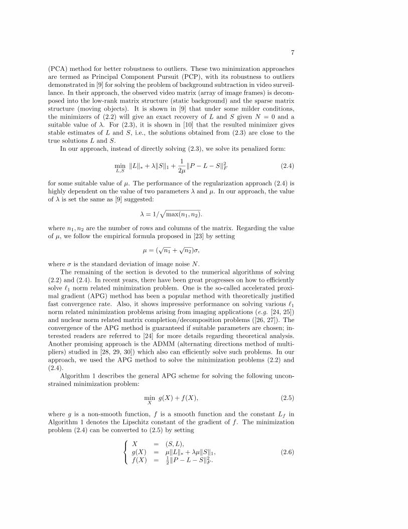
In our approach, instead of directly solving (2.3), we solve its penalized form:
minL,S‖L‖∗ + λ‖S‖1 +
1
2µ‖P − L− S‖2F (2.4)
for some suitable value of µ. The performance of the regularization approach (2.4) ishighly dependent on the value of two parameters λ and µ. In our approach, the valueof λ is set the same as [9] suggested:
λ = 1/√
max(n1, n2).
where n1, n2 are the number of rows and columns of the matrix. Regarding the valueof µ, we follow the empirical formula proposed in [23] by setting
µ = (√n1 +
√n2)σ,
where σ is the standard deviation of image noise N .The remaining of the section is devoted to the numerical algorithms of solving
(2.2) and (2.4). In recent years, there have been great progresses on how to efficientlysolve `1 norm related minimization problem. One is the so-called accelerated proxi-mal gradient (APG) method has been a popular method with theoretically justifiedfast convergence rate. Also, it shows impressive performance on solving various `1norm related minimization problems arising from imaging applications (e.g. [24, 25])and nuclear norm related matrix completion/decomposition problems ([26, 27]). Theconvergence of the APG method is guaranteed if suitable parameters are chosen; in-terested readers are referred to [24] for more details regarding theoretical analysis.Another promising approach is the ADMM (alternating directions method of multi-pliers) studied in [28, 29, 30]) which also can efficiently solve such problems. In ourapproach, we used the APG method to solve the minimization problems (2.2) and(2.4).
Algorithm 1 describes the general APG scheme for solving the following uncon-strained minimization problem:
minX
g(X) + f(X), (2.5)
where g is a non-smooth function, f is a smooth function and the constant Lf inAlgorithm 1 denotes the Lipschitz constant of the gradient of f . The minimizationproblem (2.4) can be converted to (2.5) by setting X = (S,L),
g(X) = µ‖L‖∗ + λµ‖S‖1,f(X) = 1
2‖P − L− S‖2F .
(2.6)
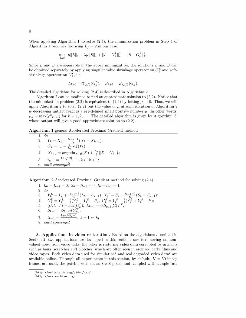
8
When applying Algorithm 1 to solve (2.4), the minimization problem in Step 4 ofAlgorithm 1 becomes (noticing Lf = 2 in our case)
minL,S
µ‖L‖∗ + λµ‖S‖1 + ‖L−GLk ‖2F + ‖S −GSk ‖2F .
Since L and S are separable in the above minimization, the solutions L and S canbe obtained separately by applying singular value shrinkage operator on GLk and soft-shrinkage operator on GSk , i.e.
Lk+1 = Dµ/2(GLk ), Sk+1 = Sλµ/2(GSk ).
The detailed algorithm for solving (2.4) is described in Algorithm 2.Algorithm 2 can be modified to find an approximate solution to (2.2). Notice that
the minimization problem (2.2) is equivalent to (2.4) by letting µ→ 0. Thus, we stillapply Algorithm 2 to solve (2.2) but the value of µ at each iteration of Algorithm 2is decreasing until it reaches a pre-defined small positive number µ. In other words,µk = max(ρkµ, µ) for k = 1, 2, . . .. The detailed algorithm is given by Algorithm 3,whose output will give a good approximate solution to (2.2).
Algorithm 1 general Accelerated Proximal Gradient method
1. do2. Yk = Xk + tk−1−1
tk(Xk −Xk−1);
3. Gk = Yk − 1Lf∇f(Yk);
4. Xk+1 = arg minX g(X) +Lf
2 ‖X −Gk‖2F ;
5. tk+1 =1+√
4t2k+1
2 , k ← k + 1;6. until converged
Algorithm 2 Accelerated Proximal Gradient method for solving (2.4)
1. L0 = L−1 = 0; S0 = S−1 = 0; t0 = t−1 = 1;2. do3. Y Lk = Lk + tk−1−1
tk(Lk − Lk−1), Y Sk = Sk + tk−1−1
tk(Sk − Sk−1);
4. GLk = Y Lk − 12 (Y Lk + Y Sk − P ), GSk = Y Sk − 1
2 (Y Lk + Y Sk − P );5. (U,Σ, V ) = svd(GLk ), Lk+1 = USµ/2(Σ)V T ;6. Sk+1 = Sλµ/2(GSk );
7. tk+1 =1+√
4t2k+1
2 , k + 1← k;8. until converged
3. Applications in video restoration. Based on the algorithms described inSection 2, two applications are developed in this section: one is removing random-valued noise from video data; the other is restoring video data corrupted by artifactssuch as hairs, scratches and blotches, which are often seen in archived early films andvideo tapes. Both video data used for simulation1 and real degraded video data2 areavailable online. Through all experiments in this section, by default, K = 50 imageframes are used, the patch size is set as 8 × 8 pixels and sampled with sample rate
1http://media.xiph.org/video/derf2http://www.archive.org

9
Algorithm 3 Accelerated Proximal Gradient method for solving (2.2)
1. L0 = L−1 = 0; S0 = S−1 = 0; t0 = t−1 = 1; µ0 > µ > 0, ρ < 1;2. do3. Y Lk = Lk + tk−1−1
tk(Lk − Lk−1), Y Sk = Sk + tk−1−1
tk(Sk − Sk−1);
4. GLk = Y Lk − 12 (Y Lk + Y Sk − P ), GSk = Y Sk − 1
2 (Y Lk + Y Sk − P );5. (U,Σ, V ) = svd(GLk ), Lk+1 = USµk/2(Σ)V T ;6. Sk+1 = Sλµk/2(GSk );
7. tk+1 =1+√
4t2k+1
2 ; µk+1 = max(ρµk, µ); k + 1← k;8. until converged
4 pixels each along both axes. For each reference patch, 5 patches with the highestmatching score in each image frame are selected. Thus, totally 250 patches are stackedfor the reference patch in our experiments, which leads to the size of each patch matrixused in our algorithm being 64 × 250. The default value of ρ in Algorithm 3 is 5/8and the default value of µ = 10−6µ. For the purpose of computational efficiency, themaximum number of the iterations of Algorithm 2 and Algorithm 3 is set as 20.
3.1. Video denoising. There are many type of image noise sources for imagedata in practice ([31]). Some main types of image noise include amplifier noise (Gaus-sian noise), photon shot noise, impulse noise and quantization noise. Impulse noiseoften arises in data acquisition and transmission due to faulty sensor or transmissionerrors ([32]). For example, as a result of electronic noise, there will be ”snow” (randomdot pattern) seen in video and television with poor (analog) television reception or onVHS tapes. How to remove impulse noise is one important problem in image/videorestoration. There are two main types of impulse noise: salt-and-pepper noise andrandom-valued impulse noise. The definitions of these two types of impulse noise aregiven as follows. Let xij and Sp(xi,j) denote the original intensity value of a givenpixel and the value corrupted by impulse noise respectively. Let the dynamic rangeof intensity value is [dmin, dmax] (dmin = 0, dmax = 255 in our experiments).
• Salt-and-pepper noise: a certain proportion of pixels are altered to be either dminor dmax, i.e
Sp(xij) =
dmin, with probability s/2
dmax, with probability s/2
xij , with probability (1− s)
where s is the level of salt-and-pepper noise.
• Random valued impulse noise: a certain proportion of pixels are altered to be a(uniform) random number in [dmin, dmax]
Sp(xij) =
dij , with probability r
xij , with probability (1− r)
where dij is a uniformly distribution random number in [dmin, dmax] and r isthe level of random-valued noise.
As salt-and-pepper noise only takes two extreme values, it is much easier to detectthan random-valued noise does. Thus, in [8], salt-and-pepper noise is first detected by

10
the adaptive median filters ([19]). Then the damaged pixels are explicitly discardedand the problem of image denoising becomes an image inpainting problem. Goodresults are reported in [8]. However, such a two-stage approach does not work forrandom-valued noise as it is very hard to be accurately detected and to be removedthereafter. As Gaussian noise is the most prevailing type of image noise, we assumethat the video data is corrupted by both Gaussian noise and random-valued impulsenoise.
Different from the two-stage methods, our proposed approach simultaneouslyidentify and remove outliers. In our approach, the random-valued impulse noise isviewed as outliers. Then Algorithm 2 can be universally used to remove either salt-and-pepper noise or random-valued noise, as Algorithm 2 does not require the priorknowledge of the locations of outliers. In the experiments, we only focus on the perfor-mance of removing random-valued noise as the performance of existing random-valuednoise removers is not satisfactory in practice.
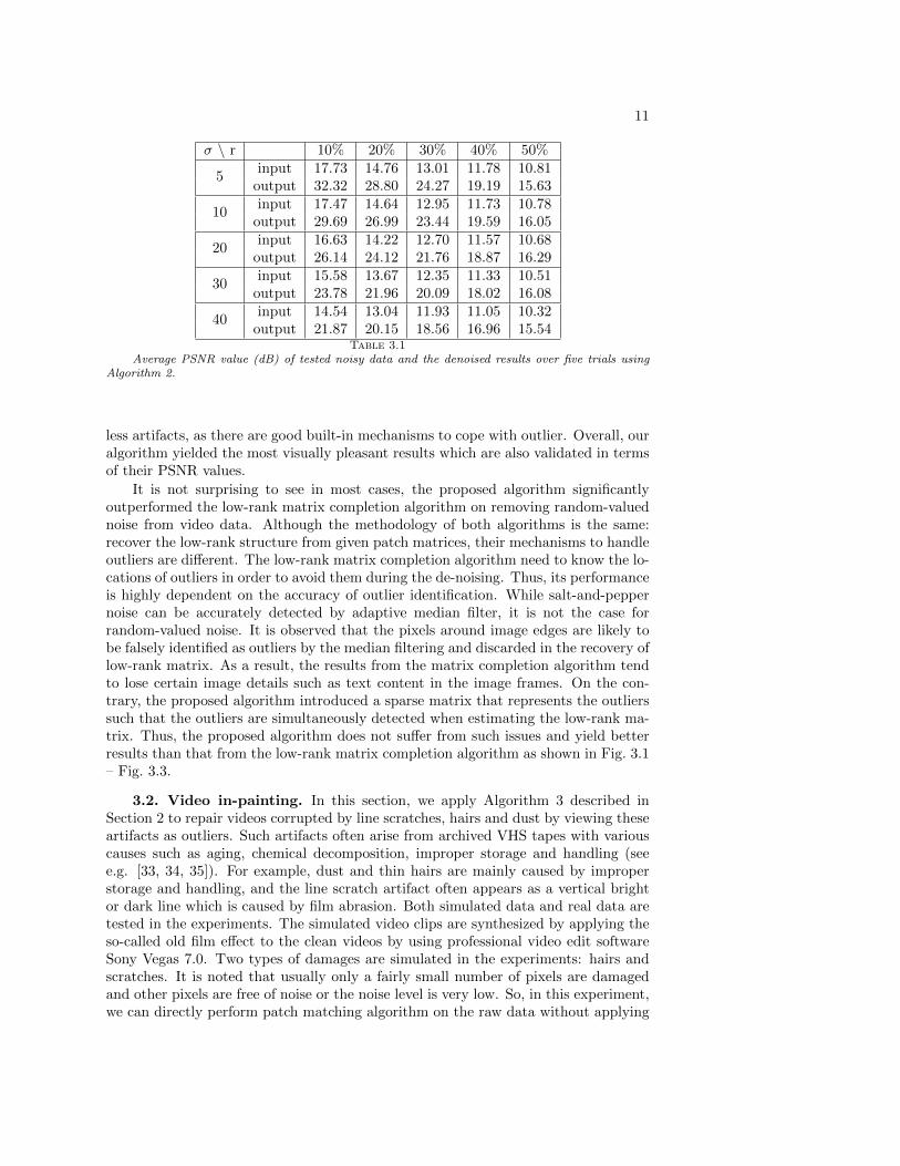
The performance of the proposed algorithm in terms of the PSNR value is illus-trated in Table 3.1 with respect to different noise levels. The experiment is carriedon the “mobile” video sequence with one key frame shown in Fig. 3.1 (a). The im-age noise is mixed by both Gaussian white noise and random-valued impulse noise.The standard deviation of Gaussian noise σ varies from 5 to 40, and the percentageof pixels corrupted by impulse noise r varies from 10% to 50%. The average PSNRvalues of one de-noised image over 5 trials are given in Table 3.1. It is seen that theperformance decreases more rapidly with the increasing of random-valued impulsenoise level than that with the increasing of Gaussian noise level. In other words,random-valued impulse noise is more difficult to remove than Gaussian noise does.The observation is not surprising as the information of the original intensity valueof the pixel is completely lost when corrupted by random-valued noise, but partialinformation is still kept when the pixel is corrupted by Gaussian white noise.
Our approach is compared against four related patch-based video denoising algo-rithms: the VBM3D (video block matching and 3D filtering) method by [5], the LRC(long range correction) method by [16], the PCA (Principal Component Analysis)method by [17] and the MC (low-rank matrix completion) method by [8]. Since theVBM3D method and the PCA method do not have built-in mechanisms to handlethe outliers. The results are quite poor when directly applying them to remove mixednoise from data. Thus, we first apply the widely used center weighted adaptive me-dian filter (see [20] for more details) on the given video data to remove outliers, thenfeed the pre-processed data to two methods for de-noising. In the experiments, theVBM3D method uses its own internal patch matching procedure. The LRC method,the PCA method, the MC method and the proposed algorithms use the same patchmatching algorithm described in Section 2.2. The data used in the patch matchingalgorithm is the data pre-filtered by the center weighted adaptive median filter.
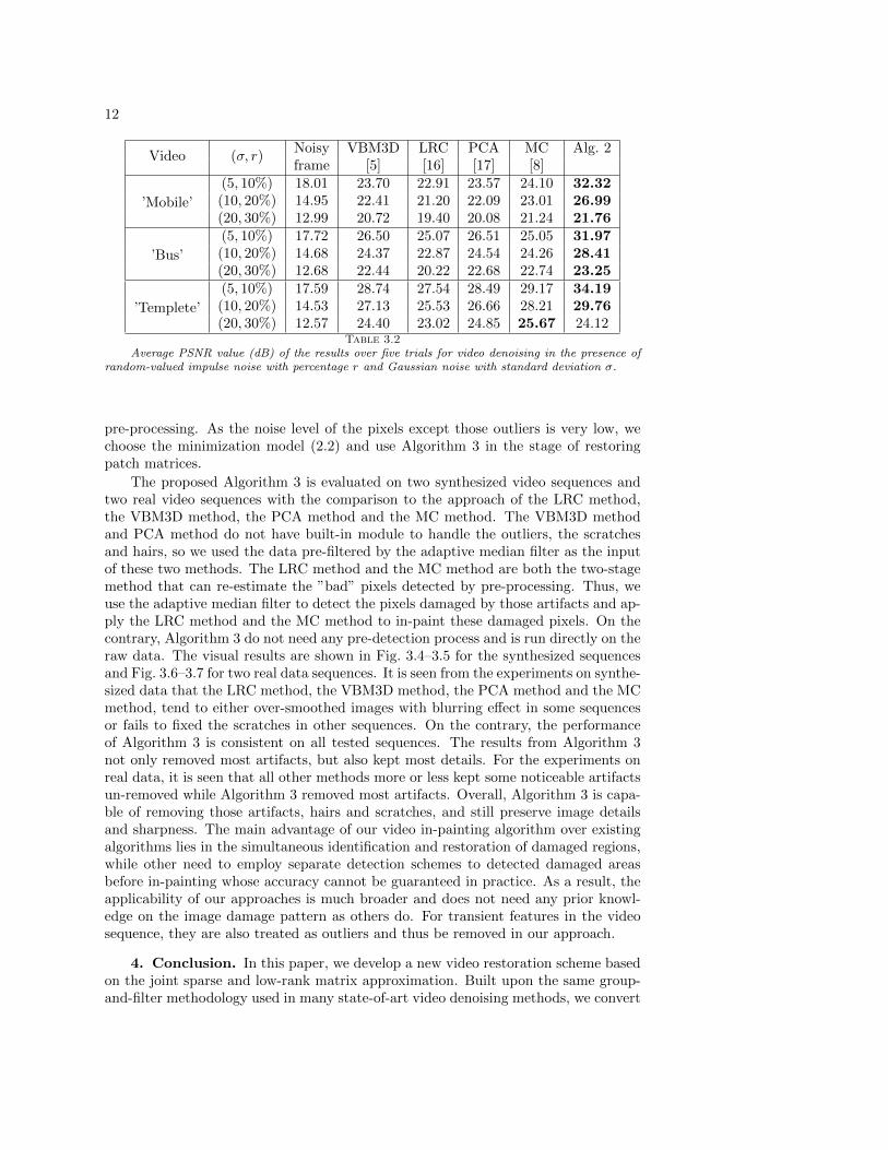
Three video sequences are used for the experimental evaluation with both Gaus-sian white noise and random-valued impulse noise added. Table 3.2 listed the averagePSNR values over 5 trials of the results from all listed methods. Clearly, the proposedmethod outperformed all other methods in most tested data sets with noticeable gainsin terms of PSNR value. The same conclusion also holds in terms of visual quality.The original clean data, corrupted one and the recovered results from all five methodsare shown in Fig. 3.1 – Fig. 3.3 (d)–(h) respectively. It is seen that the results from theVBM3D method, the LRC method and the PCA method showed severe distortions,especially in the cluttered areas. The results from MC method is the second best with
11
σ \ r 10% 20% 30% 40% 50%input 17.73 14.76 13.01 11.78 10.81
5output 32.32 28.80 24.27 19.19 15.63input 17.47 14.64 12.95 11.73 10.78
10output 29.69 26.99 23.44 19.59 16.05input 16.63 14.22 12.70 11.57 10.68
20output 26.14 24.12 21.76 18.87 16.29input 15.58 13.67 12.35 11.33 10.51
30output 23.78 21.96 20.09 18.02 16.08input 14.54 13.04 11.93 11.05 10.32
40output 21.87 20.15 18.56 16.96 15.54
Table 3.1Average PSNR value (dB) of tested noisy data and the denoised results over five trials using
Algorithm 2.
less artifacts, as there are good built-in mechanisms to cope with outlier. Overall, ouralgorithm yielded the most visually pleasant results which are also validated in termsof their PSNR values.
It is not surprising to see in most cases, the proposed algorithm significantlyoutperformed the low-rank matrix completion algorithm on removing random-valuednoise from video data. Although the methodology of both algorithms is the same:recover the low-rank structure from given patch matrices, their mechanisms to handleoutliers are different. The low-rank matrix completion algorithm need to know the lo-cations of outliers in order to avoid them during the de-noising. Thus, its performanceis highly dependent on the accuracy of outlier identification. While salt-and-peppernoise can be accurately detected by adaptive median filter, it is not the case forrandom-valued noise. It is observed that the pixels around image edges are likely tobe falsely identified as outliers by the median filtering and discarded in the recovery oflow-rank matrix. As a result, the results from the matrix completion algorithm tendto lose certain image details such as text content in the image frames. On the con-trary, the proposed algorithm introduced a sparse matrix that represents the outlierssuch that the outliers are simultaneously detected when estimating the low-rank ma-trix. Thus, the proposed algorithm does not suffer from such issues and yield betterresults than that from the low-rank matrix completion algorithm as shown in Fig. 3.1– Fig. 3.3.
3.2. Video in-painting. In this section, we apply Algorithm 3 described inSection 2 to repair videos corrupted by line scratches, hairs and dust by viewing theseartifacts as outliers. Such artifacts often arise from archived VHS tapes with variouscauses such as aging, chemical decomposition, improper storage and handling (seee.g. [33, 34, 35]). For example, dust and thin hairs are mainly caused by improperstorage and handling, and the line scratch artifact often appears as a vertical brightor dark line which is caused by film abrasion. Both simulated data and real data aretested in the experiments. The simulated video clips are synthesized by applying theso-called old film effect to the clean videos by using professional video edit softwareSony Vegas 7.0. Two types of damages are simulated in the experiments: hairs andscratches. It is noted that usually only a fairly small number of pixels are damagedand other pixels are free of noise or the noise level is very low. So, in this experiment,we can directly perform patch matching algorithm on the raw data without applying
12
Noisy VBM3D LRC PCA MC Alg. 2Video (σ, r)
frame [5] [16] [17] [8](5, 10%) 18.01 23.70 22.91 23.57 24.10 32.32(10, 20%) 14.95 22.41 21.20 22.09 23.01 26.99’Mobile’(20, 30%) 12.99 20.72 19.40 20.08 21.24 21.76(5, 10%) 17.72 26.50 25.07 26.51 25.05 31.97(10, 20%) 14.68 24.37 22.87 24.54 24.26 28.41’Bus’(20, 30%) 12.68 22.44 20.22 22.68 22.74 23.25(5, 10%) 17.59 28.74 27.54 28.49 29.17 34.19(10, 20%) 14.53 27.13 25.53 26.66 28.21 29.76’Templete’(20, 30%) 12.57 24.40 23.02 24.85 25.67 24.12
Table 3.2Average PSNR value (dB) of the results over five trials for video denoising in the presence of
random-valued impulse noise with percentage r and Gaussian noise with standard deviation σ.
pre-processing. As the noise level of the pixels except those outliers is very low, wechoose the minimization model (2.2) and use Algorithm 3 in the stage of restoringpatch matrices.
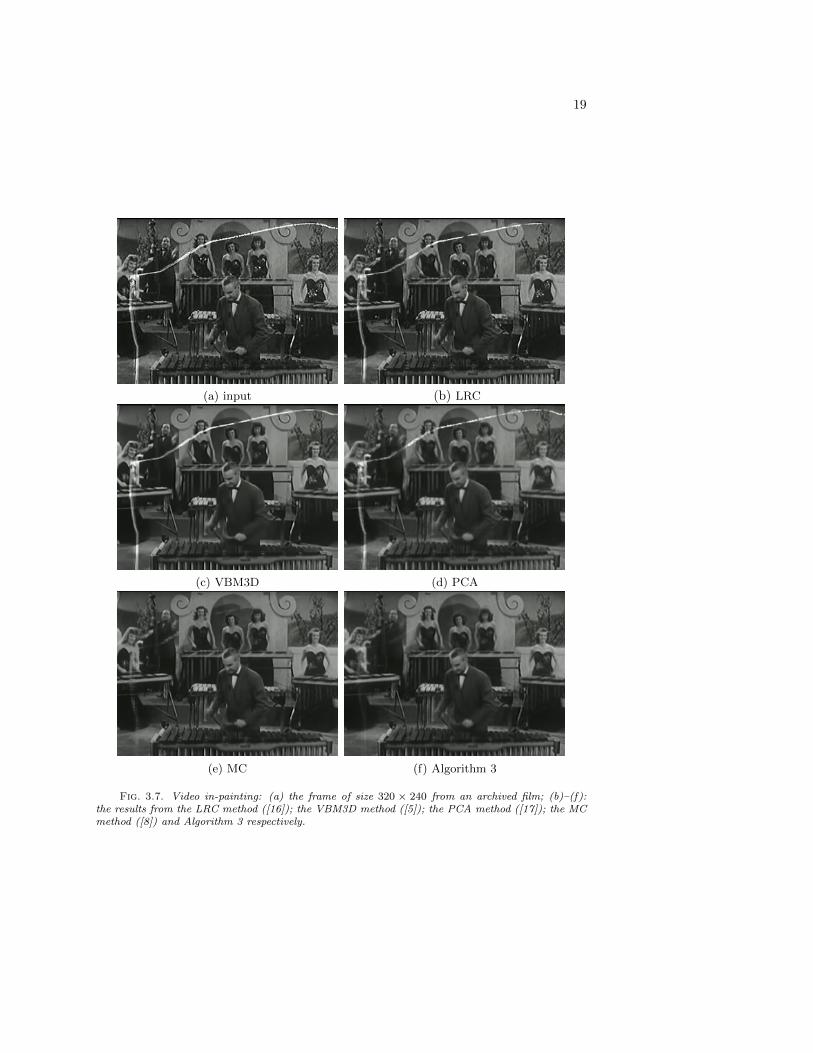
The proposed Algorithm 3 is evaluated on two synthesized video sequences andtwo real video sequences with the comparison to the approach of the LRC method,the VBM3D method, the PCA method and the MC method. The VBM3D methodand PCA method do not have built-in module to handle the outliers, the scratchesand hairs, so we used the data pre-filtered by the adaptive median filter as the inputof these two methods. The LRC method and the MC method are both the two-stagemethod that can re-estimate the ”bad” pixels detected by pre-processing. Thus, weuse the adaptive median filter to detect the pixels damaged by those artifacts and ap-ply the LRC method and the MC method to in-paint these damaged pixels. On thecontrary, Algorithm 3 do not need any pre-detection process and is run directly on theraw data. The visual results are shown in Fig. 3.4–3.5 for the synthesized sequencesand Fig. 3.6–3.7 for two real data sequences. It is seen from the experiments on synthe-sized data that the LRC method, the VBM3D method, the PCA method and the MCmethod, tend to either over-smoothed images with blurring effect in some sequencesor fails to fixed the scratches in other sequences. On the contrary, the performanceof Algorithm 3 is consistent on all tested sequences. The results from Algorithm 3not only removed most artifacts, but also kept most details. For the experiments onreal data, it is seen that all other methods more or less kept some noticeable artifactsun-removed while Algorithm 3 removed most artifacts. Overall, Algorithm 3 is capa-ble of removing those artifacts, hairs and scratches, and still preserve image detailsand sharpness. The main advantage of our video in-painting algorithm over existingalgorithms lies in the simultaneous identification and restoration of damaged regions,while other need to employ separate detection schemes to detected damaged areasbefore in-painting whose accuracy cannot be guaranteed in practice. As a result, theapplicability of our approaches is much broader and does not need any prior knowl-edge on the image damage pattern as others do. For transient features in the videosequence, they are also treated as outliers and thus be removed in our approach.
4. Conclusion. In this paper, we develop a new video restoration scheme basedon the joint sparse and low-rank matrix approximation. Built upon the same group-and-filter methodology used in many state-of-art video denoising methods, we convert

13
(a) Original data (b) Noisy input (c) Median filter (d) VBM3D
(e) LRC (f) PCA (g) MC (h) Algorithm 2
Fig. 3.1. Video de-noising: the image frames ares shown in the first row with their magnifiedversions shown in the second row. (a) the un-corrupted data; (b) the one corrupted by Gaussiannoise (σ = 20) and 30% random-valued impulse noise; (c)–(h): the result from the adaptive medianfiltering; the VBM3D method ([5]); the LRC method ([16]); the PCA method ([17]); the MC method([8]); and Algorithm 2 respectively.
the video restoration problem to a joint sparse and low rank matrix approximationproblem. The resulted `1 norm related minimization problem can also be efficientlysolved by many recently developed numerical methods. The proposed video restora-tion scheme is used to solve two video restoration problems: video denoising in thepresence of random-valued noise and video in-painting for archived films. The numer-ical experiments showed the proposed video restoration method is compared favorablyagainst many existing algorithms, which justified the advantages of the proposed in-tegrated approach over those two-stage methods.
REFERENCES
[1] A. Buades, B. Coll, and J.M. Morel. A review of image denoising algorithm, with a new one.SIAM Multiscale Modeling and Simulation, 4(2):490–530, 2005.

14
(a) Original data (b) Noisy input (c) Median filter (d) VBM3D
(e) LRC (f) PCA (g) MC (h) Algorithm 2
Fig. 3.2. Video de-noising: the image frames ares shown in the first row with their magnifiedversions shown in the second row. (a) the un-corrupted data; (b) the one corrupted by Gaussiannoise (σ = 20) and 30% random-valued impulse noise; (c)–(h): the result from the adaptive medianfiltering; the VBM3D method ([5]); the LRC method ([16]); the PCA method ([17]); the MC method([8]); and Algorithm 2 respectively.
[2] K. Dabov, V. Katkovnik R. Foi, K. Egiazarian, and S. Member. Image denoising by sparse 3dtransform-domain collaborative filtering. IEEE Trans. Image Processing, 16(8):2080–2095,2007.
[3] A. Criminisi, P. Perez, and K. Toyama. Region filling and object removal by exemplar-basedimage inpainting. IEEE Tran. Image Processing, 13(9):1200–1212, 2004.
[4] M. Mahmoudi and G. Sapiro. Fast image and video denoising via non-local means of similarneighborhoods. IEEE signal processing letters, 12(12):839–842, 2005.
[5] K. Dabov, A. Foi, and K. Egiazarian. Video denoising by sparse 3d transform-domain collab-orative filtering. In Proc. 15th European Signal Processing Conference, 2007.
[6] R. H. Chan, C. W. Ho, and M. Nikolova. Salt-and-pepper noise removal by median-type noisedetector and edge preserving regularization. IEEE Trans. Image Processing, 14(10):1479–1485, 2005.
[7] Y. Xiao, T. Zeng, J. Yu, and M. Ng. Restoration of images corrupted by mixed gaussian-impulsenoise via l1-l0 minimization. Technical Report 10-05, HKBU, 2010.
[8] H. Ji, C. Liu, Z. Shen, and Y. Xu. Robust matrix completion by using low rank matrixcompletion. In IEEE CVPR, 2010.
[9] E. J. Candes, X. Li, Y. Ma, and J. Wright. Robust principal component analysis? Technicalreport, Stanford University, 2010. preprint, 2009.
[10] Z. Zhou, X. Li, J. Wright, E. J. Candes, and Y. Ma. Stable principal component pursuit. In

15
(a) Original data (b) Noisy input (c) Median filter (d) VBM3D
(e) LRC (f) PCA (g) MC (h) Algorithm 2
Fig. 3.3. Video de-noising: the image frames ares shown in the first row with their magnifiedversions shown in the second row. (a) the un-corrupted data; (b) the one corrupted by Gaussiannoise (σ = 20) and 30% random-valued impulse noise; (c)–(h): the result from the adaptive medianfiltering; the VBM3D method ([5]); the LRC method ([16]); the PCA method ([17]); the MC method([8]); and Algorithm 2 respectively.
Proceedings of IEEE International Symposium on Information Technology (ISIT), 2010.[11] M. Elad and M. Aharon. Image denoising via sparse and redundant representations over learned
dictionaries. IEEE Trans. Image Processing, 15(12), 2006.[12] M. Protter and M. Elad. Image sequence denoising via sparse and redundant representations.
IEEE Trans. Image Processing, 18(1):27–36, 2009.[13] M. Bertalmio, G. Sapiro, V. Caselles, and C. Ballester. Image inpainting. In SIGGRAPH,
pages 417–424, 2000.[14] Z. Xu and J. Sun. Image inpainting by patch propagation using patch sparsity. IEEE Tran.
Image Processing, 19(5):1153 – 1165, 2010.[15] A. Wong and J. Orchard. A nonlocal-means approach to exemplar-based inpainting. In IEEE
ICIP, pages 2600–2603, 2008.[16] D. Zhang and Z. Wang. Image information restoration based on long-range correlation. IEEE
Trans. Circuits Syst. Video Tech., 12(5):331–341, 2002.[17] L. Zhang, S. Vaddadi, H. Jin, and S. K. Nayar. Multiple view image denoising. In ICCV, 2009.[18] E. J. Candes and B. Recht. Exact matrix completion via convex optimization. Found. of
Comput. Math, 9:717–772, 2009.

16
(a) Original data (b) Noisy input (c) Median filter (d) VBM3D
(e) LRC (f) PCA (g) MC (h) Algorithm 2
Fig. 3.4. Video in-painting: the full images frames are shown in the first row with theirmagnified regions shown in the second row. (a) the un-corrupted data; (b) the one corrupted byscratches and hairs; (c)–(h): the result from the adaptive median filtering; the VBM3D method([5]); the LRC method ([16]); the PCA method ([17]); the MC method ([8]); and Algorithm 2respectively.
[19] H. Hwang and R.A. Haddad. Adaptive median filters: new algorithms and results. IEEETrans. Image Processing, 4(4):499–502, 1995.
[20] T. Chen and H. Wu. Adaptive impulse dectection using center-weighted median filters. IEEESignal Processing Letters, 8(1):1–3, 2001.
[21] J.-F. Cai, E. J. Candes, and Z. Shen. A singular value thresholding algorithm for matrixcompletion. SIAM J. on Optimization, 20(4):1956–1982.
[22] B. Liu and A. Zaccarin. New fast algorithm for the estimation of block motion vector. IEEETransactions on Circuits and Systems for Video Technology, 3(2), 1993.
[23] E. J. Candes and Y. Plan. Matrix completion with noise. Proceedings of the IEEE, 2010.[24] A. Beck and M. Teboulle. A fast iterative shrinkage-thresholding algorithm for linear inverse
problems. SIAM J. Imaging Sci., 2(1):183–202, 2009.[25] Z. Shen, K.C. Toh, and S. Yun. An accelerated proximal gradient algorithm for frame based
image restoration via the balanced approach. Technical report, National University ofSingapore, 2009. preprint, 2009.
[26] K.C. Toh and S. Yun. An accelerated proximal gradient algorithm for nuclear norm regularizedleast squares problems. Pacific J. Optimization, 6:615–640, 2010. In press, 2009.
[27] Z. Lin, A. Ganesh, J. Wright, L. Wu, M. Chen, and Y. Ma. Fast convex optimization algorithmsfor exact recovery of a corrupted low-rank matrix. Uilu-eng-09-2214, UIUC, Jul. 2009.
[28] X. Yuan and J. Yang. Sparse and low-rank matrix decomposition via alternating directionmethods. Technical report, HKBU, 2009.

17
(a) Original data (b) Noisy input (c) Median filter (d) VBM3D
(e) LRC (f) PCA (g) MC (h) Algorithm 2
Fig. 3.5. Video in-painting: the full images frames are shown in the first row with theirmagnified regions shown in the second row. (a) the un-corrupted data; (b) the one corrupted byscratches and hairs; (c)–(h): the result from the adaptive median filtering; the VBM3D method([5]); the LRC method ([16]); the PCA method ([17]); the MC method ([8]); and Algorithm 2respectively.
[29] Z. Lin, M. Chen, L. Wu, and Y. Ma. The augmented lagrange multiplier method for exactrecovery of corrupted low-rank matrices. Uilu-eng-09-2215, UIUC, Oct. 2009.
[30] Tao and Yuan. Recovering low-ran and sparse components of matrices from incomplete andnoisy observations. SIAM J. Optimization, 21(57), 2011.
[31] G. Healey and R. Kondepudy. Radiometric ccd camera calibration and noise estimation. IEEETrans. PAMI, 16(3):267–276, 1994.
[32] A.C. Bovik. Handbook of Image and Video Processing. Academic Press Inc., San Diego, CA,2000.
[33] L. Joyeux, O. Buisson, B. Besserer, and S. Boukir. Detection and removal of line scratches inmotion picture films. In IEEE CVPR, 1999.
[34] L. Joyeux, S. Boukir, B. Besserer, and O. Buisson. Reconstruction of degraded image sequences.application to film restoration. Image Vis. Comput., (19):503–516, 2001.
[35] A. C. Kokaram. On missing data treatment for degraded video and film archives: a survey anda new bayesian approach. IEEE Trans. Image Processing, 13(3):397–415, 2004.

18
(a) input (b) LRC
(c) VBM3D (d) PCA
(e) MC (f) Algorithm 3
Fig. 3.6. Video in-painting: (a) the frame of size 261 × 201 from an archived film; (b)–(f):the results from the LRC method ([16]); the VBM3D method ([5]); the PCA method ([17]); the MCmethod ([8]) and Algorithm 3 respectively.
19
(a) input (b) LRC
(c) VBM3D (d) PCA
(e) MC (f) Algorithm 3
Fig. 3.7. Video in-painting: (a) the frame of size 320 × 240 from an archived film; (b)–(f):the results from the LRC method ([16]); the VBM3D method ([5]); the PCA method ([17]); the MCmethod ([8]) and Algorithm 3 respectively.