robustness evaluation and tool optimization in … · robustness evaluation and tool optimization...
TRANSCRIPT
1
Robustness evaluation and tool optimization in forming applications
Priv.-Doz. Dr.-Ing. Welf-Guntram Drossel1, Markus Israel1, Tobias Falk1
1 Fraunhofer Institute for Machine Tools and Forming Technology IWU
Summary
Mechanical joining technologies are becoming increasingly important with the trend towards light and multi-material designs in the automotive industry. Providing robust connection techniques will be of particular importance. Thus, rejection rates are reduced and costs are cut in the parts production. This lecture discusses the example of clinching and its potentials and limits concerning FE-based sensitivity analysis and optimization for the joining by forming technology.
By determining the sensitivity of the design for relevant connection parameters, the most important values for the optimization of the forming die are derived. On this basis, both appropriate tools for a particular material combination and other tools for the joining of different thicknesses and sheet materials are designed. Furthermore, a sensitivity analysis of uncertain variables allows to evaluate the robustness of the clinching process in production. Based on these results, methods to increase process robustness or process monitoring in terms of quality assurance can be derived.
Keywords: mechanical joining, clinching, sensitivity analysis, die optimization

9th Weimarer Optimization and Stochastic Days – November 29-30, 2012 2
1 Introduction
Mass manufacturing processes are subjected to parameter variations, which can cause fluctuations of characteristic result values. Also, in the mechanical joining technology, there are numerous tasks regarding sensitivity analysis, robustness evaluation or optimization. Especially in terms of efficiency and reducing costs, standardization of tool sets for various compounds are great issues. In Kuehne (2007), on the example of the Mercedes S-Class, the potential of such an analysis of different clinching tasks is shown. Such a complex and comprehensive analysis is very expensive, and so, the use of FEM in the process development and process evaluation is significantly increasing. Relating to Held (2009), the ever-growing use of simulation programs at all stages of component manufacturing is caused primarily by the automobile manufacturers to expand the understanding of the process continuously and to exploit cost saving potential. A sensitivity analysis and robustness evaluation provide at an early stage of development, the definition of appropriate measures to ensure the process and, thus, the product quality (Will 2005). Therefore, the numerical robustness is of special importance in order to improve properties and to reduce production costs in the virtual development process (Roos 2004). It is essential, particularly in terms of design and quality assurance of mechanical joining, to have proper knowledge of the amount and sensitivity of each influencing parameter variation and tolerance on the joining process. For assessment, sensitivity analysis and robustness evaluation are required. A successful application of a finite element based approach for sensitivity analysis coupled with an appropriate statistical design of experiments (DOE) have not yet been found in the mechanical joining technology. Clinching is an important mechanical joining technique, which is standardized according to DIN 8593. Clinching is defined as a mechanical joining process producing a connec-tion between two or more sheets exclusively by a local forming operation. The joining process is divided into three sub-processes (see figure 1). In the upsetting step (B), the punch pushes the joining area off the sheet plane. While punching, the sheet material is now pressed down to the die bottom. Further punch stroke increases the radial flow of the material between punch and die filling the die shape and realizing the interlock of the sheets (C).
Figure 1: clinching of round points with rigid die; left: method; right: typical cross sections
To evaluate the affecting parameters, defined result variables are required. For clinching, these are mainly the neck thickness tn and the interlock f (see figure 2) as far as the evaluation of the load capacity of compounds is concerned. The thickness of the bottom tb

9th Weimarer Optimization and Stochastic Days – November 29-30, 2012 3
is seen as a constant parameter in a normal forming process, which is set in advance in the sampling process and can be non-destructively tested using a thickness gauge (Steinhauer 2007).
Figure 2: Relevant geometrical parameter of a clinching joint related to DVS (2009) The numerical description of clinching is subject of numerous studies and FEM-based projects. In Dietrich (2006), Paula (2007), Lee (2010), Mucha (2011) and other sources, suitable tool geometries to improve the forming of the joint and the joint strength under pull-out tension were numerically, but iteratively identified. Initial findings about the FEM-based optimization of clinching processes based on the Taguchi method and the Response Surface Method were obtained in Oudjene (2008) and Oudjene (2009). However, numerical sensitivity analysis and robustness evaluation with more than two parameters based on statistical design of experiments have not been conducted yet. In principle, the statistical-numerical analysis of clinching has to be divided into two categories. A key aspect is the provision of appropriate die and process parameters (design parameters) for an optimal joining. For this purpose, the first type deals with the identification of relevant parameters using sensitivity analysis and a required subsequent process of optimization. The second type of analysis is concerned with the identification and evaluation of process robustness, i.e. result value variations caused by process uncertainties (e.g. friction, material strength variations). Both types of analysis will be considered in the following.
2 Setup of a stochastic analysis of clinching
For the numerical description of the clinching process, the FEM-software Deform is used, which was developed specifically for solid forming processes. Important for the calculation of forming processes, such as clinching, is the possibility of a re-meshing option. Thus, areas of strong deformation and the resulting geometry variations or distortions can be re-meshed and the new node data and element data can be transferred from the previous to the new mesh. Assuming ideal rotationally symmetrical dies and neglecting any material anisotropy, the problem can be described 2D rotationally symmetrical. The interaction between Deform and OptiSLang is assured via appropriate input and output files. Additionally, a script is required, which identifies the result variables of neck thickness and interlock on the basis of geometric features and transfers them to the output file. In advance, the FEM model has to be parameterized.
do - outer diameter
di - inner diameter
f - interlock
h - forming height of the joint
tb - thickness of the bottom
tn - thickness of the neck (is zero with both
side cut elements)
tt - total sheet thickness
t1 - single sheet thickness, punch side
t2 - single sheet thickness, die side

9th Weimarer Optimization and Stochastic Days ï November 29-30, 2012 4
Red Line = Simulation
frictional combination
(friction factor model)
1 punch – upper sheet
2 blank holder – upper sheet
3 upper sheet – bottom sheet
4 die – bottom sheet
Figure 3: FEM-model (left) and comparison of cross sections experiment and simulation (top right, FEM-result: red line)
Subject of the analysis is the material combination EN AW-6016 with a thickness combination of 1.5 mm in 1.0 mm. Figure 3 shows the Finite-Element Model in the initial state and the comparison of cross section of simulation and experiment. An important basis for the numerical calculation of the forming process is the material flow curve, which indicates the flow stress concerning the state of forming. The friction values are based on experience being currently iteratively adjusted for the correlation of joint forming and load in experiment and simulation. This provides a perspective option to optimize friction values with the objective of creating the best possible correlation in the experimental verification of the simulation.
3 Sensitivity analysis according to design parameters
3.1 Design parameters and result values The design of the clinching joint essentially depends on the geometric shape of the tools, punch and die. Another influencing variable is the blank holder fixing the sheet before clinching and stripping it after the forming process. Due to known proper blank holder adjustments and because of the proven small impact of the blank holder shape and load in a technologically meaningful variation, the parameters of this device are not considered in the analysis. The following listed parameters and their variation limits are subjects of the analysis:
Figure 4: Design parameters and variation limits
Punch
Die
punch (rigid)
upper sheet (plastic)
bottom sheet (plastic)
symmetry constraint
die (rigid)
blank holder (rigid)
9th Weimarer Optimization and Stochastic Days – November 29-30, 2012 5
The relevant result values for joint strength, neck thickness and interlock have already been explained in the introduction. With regard to the dimensions of the required drive and C-frame, the joining force is another important parameter. For assessing the forming and possible damage of the sheet material due to strong deformation, both the joining force and the damage values at critical clinching points can be identified. However, the investigations are focused on the geometric parameters and the joining force.
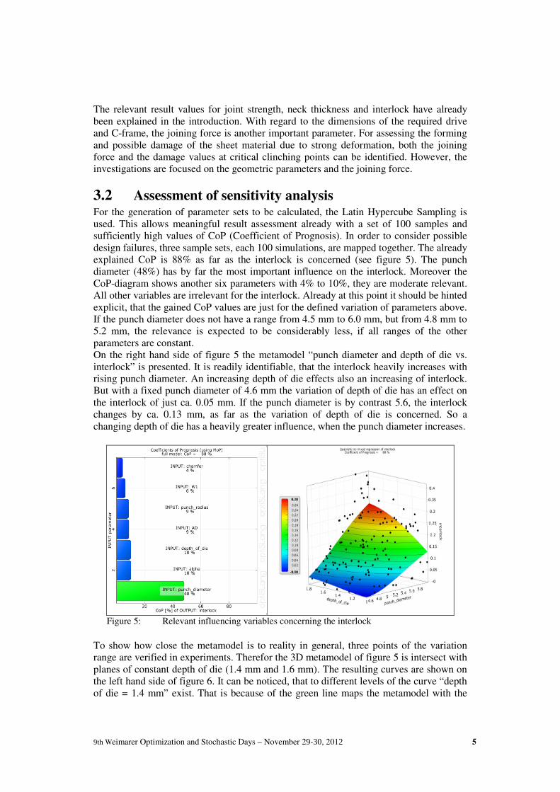
3.2 Assessment of sensitivity analysis For the generation of parameter sets to be calculated, the Latin Hypercube Sampling is used. This allows meaningful result assessment already with a set of 100 samples and sufficiently high values of CoP (Coefficient of Prognosis). In order to consider possible design failures, three sample sets, each 100 simulations, are mapped together. The already explained CoP is 88% as far as the interlock is concerned (see figure 5). The punch diameter (48%) has by far the most important influence on the interlock. Moreover the CoP-diagram shows another six parameters with 4% to 10%, they are moderate relevant. All other variables are irrelevant for the interlock. Already at this point it should be hinted explicit, that the gained CoP values are just for the defined variation of parameters above. If the punch diameter does not have a range from 4.5 mm to 6.0 mm, but from 4.8 mm to 5.2 mm, the relevance is expected to be considerably less, if all ranges of the other parameters are constant. On the right hand side of figure 5 the metamodel “punch diameter and depth of die vs. interlock” is presented. It is readily identifiable, that the interlock heavily increases with rising punch diameter. An increasing depth of die effects also an increasing of interlock. But with a fixed punch diameter of 4.6 mm the variation of depth of die has an effect on the interlock of just ca. 0.05 mm. If the punch diameter is by contrast 5.6, the interlock changes by ca. 0.13 mm, as far as the variation of depth of die is concerned. So a changing depth of die has a heavily greater influence, when the punch diameter increases.
Figure 5: Relevant influencing variables concerning the interlock
To show how close the metamodel is to reality in general, three points of the variation range are verified in experiments. Therefor the 3D metamodel of figure 5 is intersect with planes of constant depth of die (1.4 mm and 1.6 mm). The resulting curves are shown on the left hand side of figure 6. It can be noticed, that to different levels of the curve “depth of die = 1.4 mm” exist. That is because of the green line maps the metamodel with the

9th Weimarer Optimization and Stochastic Days – November 29-30, 2012 6
angle A1 = 0.5° and in opposite the red curve with A1 = 5.0°. This can explain the relation, that in tendencies the interlock decreases with an increasing angle A1. The three points of the experiments on the particular curve are marked with the circles. It can be noticed, that these three points lie very close on the metamodel curves. Summarizing it can be concluded, that a map of reality on the metamodel is given.
depth of die: 1.6 mm / angle A1: 0.5°
depth of die: 1.4 mm / angle A1: 0.5°
depth of die: 1.4 mm / angle A1: 5.0°
depth of die: 1.6 mm / angle A1: 0.5°punch diameter: 5.4 mm
depth of die: 1.4 mm / angle A1: 0.5°punch diameter: 5.4 mm
depth of die: 1.6 mm / angle A1: 5.0°punch diameter: 5.0 mm
inte
rloc
k
punch diameter
Figure 6: Verification of the metamodel with experiments
In opposite to the interlock, the punch diameter has clear a less effect on the thickness of neck. Its CoP value is reveals 18%. With a CoP value of 65% far and away the depth of die has the greatest effect on the neck thickness. The metamodel shows a decreasing neck thickness, when depth of die grows (see figure 7, right). These tendencies are confirmed in many experimental and numerical studies, such as Varis (2006) and Mucha (2011). An increasing punch diameter comes to a reduction of the neck thickness. Also known is that the thickness of the neck increases with a greater pin radius.
Figure 7: Relevant influencing variables concerning the thickness of the neck
Now an already known problematic of clinching is getting clear: Both parameter, which has the most important effects on interlock and thickness of the neck, have the tendencies to change these values contrary. With an increasing punch diameter, the interlock is getting larger, but the neck thickness decreases at once. The reversed case is detected as

9th Weimarer Optimization and Stochastic Days – November 29-30, 2012 7
far as the depth of die in concerned. This problem and other aspects will be discussed within the optimization. The joining force is the third analyzed influencing parameter. With 71% relevance, it is almost exclusively dependent on the size of the punch diameter. As expected, the joining force increases with rising punch diameter. To see the relevance of both most important parameters to get a global understanding of the process, the CoP values are worked off on the base of the OptiSLang evaluations (see figure 8). It can be seen, that the variation of the punch diameter has a high influence on most of the output parameters. But just the thickness of the neck is increasing with a decreasing punch diameter. All other significant output values are getting higher with a growing punch diameter. Interesting concerning the punch diameter, that the variation has no significant influence on the state of forming (“Umformgrad stempelseitig”) and on the maximum damage value in the neck area. Under reserve can be claimed, that a variation of the punch diameter has a massive effect on the forming of clinching point, without a significant changing of the material damage in the area of the neck. In comparison to the punch diameter the parameter depth of die has a greater effect on the neck thickness and a lower effect on the interlock. The influence on the joining force is very small. But a growing depth of die leads to a massive increasing of the state of forming and the damage value, equivalent to a growing danger of neck fractures through the joining process.
Punch diameter (4.5 � 6.0 mm) Depth of die (1.0 � 1.8 mm)
Figure 8: influence of relevant parameters on output values
4 Optimization of the clinching process
4.1 Parameter and objective values Concerning clinching, the objective value to be optimized is the joint strength, which, however, cannot be derived just from the cross section of the calculated joining. Neck thickness and interlock affect the load capacity of the clinching joint. Both values should be high with respect to increased joint strength. However, no clear assessment can be

9th Weimarer Optimization and Stochastic Days – November 29-30, 2012 8
made when a clinching point reaches its maximum load capacity. This is strongly dependent on the load direction as well as on the sheet materials and thicknesses.
Figure 9: Failure types after loading the clinching point according to DVS (2009)
Figure 9 shows the possible failure modes after point loading: neck fracture (left), pull-out failure (right) and multiple failure (center). To avoid neck fracture, the neck thickness should be maximized. Accordingly, pull-out failure can be avoided in providing the largest possible interlock. In the sensitivity analysis, punch diameter and die depth were determined as major influencing parameters concerning neck thickness and interlock. As shown in figure 5 and 7, the value tendencies as a function of these two influencing design parameters are exactly opposite. For optimizing, the parameter AD, i.e. the die bottom diameter, is also considered. The optimization is conducted by using the Adaptive Response Surface Method (ARSM) with maximizing the neck thickness as the objective function. As constraints, a minimum interlock of 0.5 x neck thickness and a maximum joining force of 30kN were defined (see figure 10).
4.2 Results of parameter optimization The diagrams of convergence in figure 11 of punch diameter, depth of die and AD are showing a relative fast convergence of these parameters. Just the thickness of bottom does not converge. This is because the thickness of bottom has no influence on the objective function. This relation was already verified in many studies: a reduction of thickness of the bottom at the end of the process has no effect on the thickness of the neck, but the interlock will grow, Hahn (2002). This parameter has at best influence on the first constraint function. Another effect can be seen at the convergence curves: simulations, which do not fulfill one or both constraint functions, are indicated with a red point, the simulations that are all right are marked green. It is easy to see, that there are more red than green points, so more simulations with parameter combinations, which do not fulfill at least one constraint function. This reason is basically because of the strict constraints. Maybe as far as this optimization problem is concerned, an adaption of the constraints has to be fulfilled (e.g. a rising for the joining force from 30 kN up to 35 kN).

9th Weimarer Optimization and Stochastic Days – November 29-30, 2012 9
Algorithm of optimization
Adaptive-Response-Surface-Method (ARSM)
Objective function
Neck thickness � max.
Constraint functions
NB1: interlock ≥ neck thickness * 0.5
NB2: joining force ≤ 30 kN
Variable parameters (min / max / step)
Punch diameter (4.5 mm / 6.0 mm / 0.1 mm) Depth of die (1.0 mm / 1.8 mm / 0.1 mm)
AD (4 mm / 6 mm / 0.1 mm)
Thickness of bottom (0.55 mm / 0.90 mm / 0.01 mm)
Iterations
20 Sets, each has 10 Designs
Figure 10: left: boundary conditions of the analysis; right: bar diagram with optimal parameters
Figure 11: diagrams of convergence of the parameters
As already mentioned, a definition of an optimal correlation between neck thickness and interlock is not possible without further analysis. Therefore, in the following optimiza-tion, the constraints defining the relation between the interlock and the neck thickness will be adjusted. Figure 12 (left) shows the starting of the optimization: the reference joining in experimental and numerical cross section. On the right side of the figure differences in the cross sections for a quotient of neck thickness / interlock of 0.25 and 0.5 can be seen. Comparing optimization 1 and FEM reference, a maximization of the
Best Design
Best Design
Best Design
Best Design
de
pth
of
die
pu
nch
dia
me
ter
AD
thic
kn
ess
of
bo
tto
m

9th Weimarer Optimization and Stochastic Days – November 29-30, 2012 10
neck thickness seems not be reached. This is because of the ambitious constraint functions, which are not fulfilled in the reference joining. This strict selection implicates
Reference
Experiment
Reference
FEM
Optimization 2
ZF: tn � max.
NB1: f ≥ tn * 0,25 NB2: F ≤ 30 kN
Var.: DS, TM, AD
Optimization 1
ZF: tn � max.
NB1: f ≥ tn * 0,50 NB2: F ≤ 30 kN
Var.: DS, TM, AD, tb
0,73
0,59
0,14
31,5
5,4
1,4
4,9
0,73
0,55
0,16
31,9
5,4
1,4
4,9
tb in mm
tn in mm
f in mm
F in kN
DS
TM
AD
0,70
0,63
0,16
30,0
5,1
1,3
5,4
0,62
0,52
0,26
28,9
5,1
1,6
5,7
Figure 12: cross sections of optimized joinings with different constraint functions an increasing interlock of 62%. A growing neck thickness (+15%) is detected in optimization 2, with an unchanged interlock and a maximal allowed joining force. Overall after these two optimizations, it is all right to say, the reference joining is quite good. The potential of the optimization as far as getting optimal tool geometries and different conditions on the clinching point are concerned, are shown. Based on these individual optima, a Pareto optimization can be conducted and, as a result, a range of optimal joining for any neck thickness and interlock relation is generated.
Algorithm of optimization
Pareto optimization
Objective functions
Zielfunktion 1: neck thickness � max.
Zielfunktion 2: interlock � max.
Constraint functions
NB1: 0.15*tn ≤ f ≤ 0.5*tn NB2: die distance ≤ 0.2 mm
Variable parameters (min / max / step)
Punch diameter (4.5 mm / 6.0 mm / 0.1 mm)
Depth of die (1.0 mm / 1.8 mm / 0.05 mm)
AD (4.0 mm / 6.0 mm / 0.1 mm)
Iterations
20 Sets, each has 10 Designs
Abort, if no chaning at the pareto front after a set (here: 17 Sets)
Figure 13: boundary conditions (left) and results (right) of Pareto optimization
In addition to the die optimization for individual joints, in practice, alternative joining solutions are increasingly sought for different sheet materials and thicknesses. The aim is
Final Paretofront
f = 0,5* tn
f = 0,15*tn

9th Weimarer Optimization and Stochastic Days – November 29-30, 2012 11
to provide a punch and die set for proper clinching of three or more different material combinations and/or thickness combinations. This problem can be also solved by using ARSM. Here, the maximum of all single-neck thicknesses is defined as the objective function (to me maximized). As constraints, the compliance of an interlock minimum of 0.1 mm and a maximum counter-piping of the blanks from the die of 0.3 mm were chosen. The four material and thickness pairings are presented in figure 14. There are also the comparisons between FEM and experiments, with very good compliances of numeric and reality. The optical comparison of the cross section lines shows a nearly perfect compliance.
Algorithm of optimization
Adaptive-Response-Surface-Method (ARSM)
Objective function
Sum of all neck thicknesses � max.
Constraint functions
NB1: interlock ≥ 0.10 mm NB2: die distance ≤ 0,30 mm
NB3: neck thickness pairing 2 ≥ 0,18 mm
Variable parameters (min / max / step)
Punch diameter (4.5 mm / 6.0 mm / 0.0 1mm) depth of die (1.0 mm / 1.8 mm / 0.01 mm)
AD (4 mm / 6 mm / 0.01 mm) thickness of the bottom (0.55 mm / 0.90 mm / 0.01 mm)
Iterations
20 Sets, each has 10 Designs
EN AW-5754 (1,51 mm) in EN AW-5754 (1,01 mm) HC340LA (1,01 mm ) in EN AW-5754 (1,51 mm)
HC340LA (1,01 mm ) in HC340LA (1,01 mm ) EN AW-5754 (1,51 mm) in HC340LA (1,01 mm )
Figure 14: compromise for four material and thickness pairings; top left: boundary
conditions; top right: bar diagram with optimal parameters; down: cross sec-tions of FEM and experiments compared
An issue can be seen, however, in the fact that for optimization a precise match of experiment and simulation is necessary. Therefore, a careful determination of parameters (flow curves) is essential. Additionally, realistic coefficients of friction for the four friction pairs have to be determined. In contrast to the sensitivity analysis, a deviation of the prediction accuracy of the FEM always leads to inaccuracies of the optimization results. Furthermore, the implementation of the material damage as a limit or objective

9th Weimarer Optimization and Stochastic Days – November 29-30, 2012 12
function has not yet been possible. For this purpose, adequate damage criteria for clinching and corresponding limits for the sheet materials still have to be investigated.
5 Sensitivity toward process uncertainties
5.1 Parameter and result responses
The clinching process is affected by a variety of process uncertainties. Material properties such as yield strength, tensile strength, breaking elongation or the sheet thickness of semi-finished products are typical to be subject of tolerances (Will 2006). Due to changes in the state of lubrication and surface shapes, during the process of clinching, the friction values also vary over a lifetime period of a die set (about 200,000 to 400,000 points). Furthermore, effects of abrasion or adhesion may occur. Here, an assessment of quantity regarding realistic limits and distribution functions is, however, very difficult to deter-mine. A locally varying intensity of deformation or associated pre-hardening of the sheets by previous forming processes (e.g. bending or deep drawing) is also possible.
Figure 15: Selection of relevant process parameters of mechanical joining subjected to
tolerances
Figure 15 shows the parameters for clinching disregarding the toll stiffness and machine stiffness in the present considerations. Looking closely at these parameter blocks, it appears they are resulting in a large number of individual values. For example, there are four frictional combinations: blank holder/sheet, punch/sheet, sheet/sheet and die/sheet. The used parameters and their related scatter ranges evaluated from the analysis are shown in figure 16. As result values, neck thickness, interlock and the joining force are evaluated compared to the design parameters in the same way as in the foregone sensitivity analysis.

9th Weimarer Optimization and Stochastic Days – November 29-30, 2012 13
Figure 16: Uncertainties and their variation limits; left: limits; right: scheme of the flow curve shift
In this robustness evaluation the input parameters should be based on a more or less realistic distribution function. Now and then it can be necessary, to assess the distribution as good as possible. As an example the normal distribution of the die-sided sheet thickness is shown in figure 17 (top, left).
5.2 Results of the robustness evaluation
Parameters most normal distributed with σ = (opper boundary – lower boundary) / 6
e.g. sheet thickness die-sided: σ = 0,033
Mean value: 0.541 mm
Sigma: 0.055 mm probability of tn < 0.45 mm: 4%
Mean value: 0.156 mm
Sigma: 0.042 mm probability of f < 0.1 mm: 9%
Mean value: 32.3 kN
Sigma: 5.1 kN probability F > 38 kN: 13%
Figure 17: top, left: normal distribution of parameter “sheet thickness die-sided”; top, right and down: frequency distribution of neck thickness, interlock and joining force
In the figure the frequency distributions of the output parameters neck thickness, interlock and joining force of the robustness analysis can be seen. For the evaluation of the robustness of a process is among others relevant, that claimed minimum values of the output parameters are reached all over the process of production. As far as clinching is concerned, this is the case for the interlock. This output should have at least a value of
interlock
neckthickness
joining force

9th Weimarer Optimization and Stochastic Days – November 29-30, 2012 14
0.1mm. Because this failure probability of 9% is too high, a method of improvement is presented (see figure 18).
Figure 18: Principle procedure to evaluate a robustness analysis and deductions of taking
action to improve the robustness After the evaluation of the failure probability (step 1), the knowledge is necessary, which parameters have the greatest influence on the critical output value (here it is the inter-lock). This may be seen, just like in a sensitivity analysis, with help of the CoP diagram (step 2). In the current example, the pin radius and the deformation on the die-sided sheet have the main effect. The direction in which they exert can be seen in the related metamodel (step 3). Critical for the interlock are small deformation values on the die-sided sheet and a large pin radius. Based on these information, thoughts to get a more robust process, have to be done. E.g. this can be realized in a robustness analysis with a reduction of the allowed abrasion of the pin radius from 0.55 mm to 0.45 mm. That means in practice higher costs, because the punch has to be exchanged more often. In figure 19 is pointed out, that this has a positive effect on the failure probability, which is then 1.5%.
Basis analysis Changed variation of parameters improved analysis
0.25 – 0.55 pin radius in mm 0.25 – 0.45
Figure 19: improved robustness of interlock
Failure
probability
ca. 1,5%
Failure
probability
ca. 9%
more robust
output parameter interlock
OUTPUT: interlock OUTPUT: interlock

9th Weimarer Optimization and Stochastic Days – November 29-30, 2012 15
The illustrated examples and the demonstrated strategies for the robustness evaluation of clinching processes show impressive the potential of a numerical robustness analysis. Similar to sensitivity analyses complex influences of parameters can be shown. The user has the possibility to study the direction of the effect and to get further information to receive a more robust clinch process. Similar to the optimization for a robustness analysis it is necessary, that a FEM model exists, that matches as good as possible with the experiment, because the defined values of output parameters are part of the evaluation.
6 Summary and Outlook
A process chain, being increasingly numerical, especially in the automotive production, requires a profound understanding of the joining processes to improve quality standards and to explore cost saving potential. So far, the various capabilities and applications of FE simulation for sensitivity analysis, robustness evaluation and optimization have not been considered much in the mechanical joining technique. The performed sensitivity and robustness analysis for clinching indicates the potential of the numerically based analysis of clinching processes. From a variety of parameters that affect the joining process, in such studies, the relevant impact parameters are filtered and being provided either for process optimization or an evaluation of the process robustness. The so obtained process knowledge exceeds the previously, often experimentally-generated, understanding and correlation studies. The possibility to assess parameters to such a complex extent and number, never been reached in experiments before, allows to obtain new insights and to find global and general correlations. Based on these initial studies for clinching, further analysis will be conducted on other frequently used mechanical joining methods. The main focus of further research in the automotive industry is on the increasingly used self-pierce riveting technique. The challenges will be the numerical description of the material separation, the expansion of computing stability and accuracy. As demonstrated in the sensitivity analysis for clinching, mechanical and technological characteristics of the materials, as well as the frictional conditions, are the basic data of the simulation representing the fundamental basis for a realistic numerical analysis. When this data is available, the CAE-based sensitivity analysis and robustness evaluation of joining processes will be a key source of information for method comparison and selection of appropriate joining technologies.
7 References/Literature
DEUTSCHES INSTITUT FÜR NORMUNG E.V.: Fertigungsverfahren Fügen, Teil 5: Fügen
durch Umformen, Einordnung, Unterteilung, Begriffe. Berlin: Beuth Verlag GmbH, 2003.
DEUTSCHER VERBAND FÜR SCHWEIßEN UND VERWANDTE VERFAHREN E.V.: Taschen-
buch DVS-Merkblätter und –Richtlinien – Mechanisches Fügen, Fachbuchreihe
Schweißtechnik, Band 153, DVS-Media GmbH, Düsseldorf, 2009.

9h Weimarer Optimization and Stochastic Days – November 29-30, 2012 16
DIETRICH, S.: Grundlagenuntersuchungen zu neuen matrizenlosen Umformfügeverfahren. Chemnitz, TU Chemnitz, Dissertation, 2006.
HAHN, O.; u.a.: Verfahrenssimulation des Durchsetzfügens kaltverfestigter Aluminium-werkstoffe zur rechnergestützten Werkzeugentwicklung. Hannover, Europäische Forschungsgesellschaft für Blechbearbeitung e.V., 2002. Forschungsbericht Nr. 183.
HELD, C.; LIEWALD, M.; SINDEL, M.: Untersuchungen zum Einfluss werkstofflicher
Schwankungen innerhalb eines Coils auf die Umformbarkeit, In: wt Werkstattstech-nik online, 2009, URL: http://www.werkstattstechnik.de/wt/get_article.php?data[a
rticle_id]=51225 (Abruf am 23.11.2009).
KÜHNE, T.: Clinchen und Kleben – Komplexer Einsatz im Mischbau. In: Adhäsion.
Kleben und Dichten 10/2007, S.32-36.
LEE, C.-J.; KIM, J.-Y.; LEE, S.-K.; KO, D.-C.; KIM, B.-M.: Design of mechanical clinching tools for joining of aluminium alloy sheets. In: Materials & Design Volume 31, Issue
4, Design of Nanomaterials and Nanostructures, April 2010, S. 1854-1861.
MUCHA, J.: The analysis of lock forming mechanism in the clinching joint. In: Materials
and Design, 2011 32 (10), S. 4943-4954.
OUDJENE, M., BEN-AYED, L.: On the parametrical study of clinch joining of metallic sheets using the Taguchi method, In: Engineering Structures, Volume 30, Issue 6, Juni 2008, S.1782-1788.
OUDJENE, M., ET AL: Shape optimization of clinching tools using the response surface methology with Moving Least-Square approximation. In: Journal of Materials Pro-
cessing Technology, Volume 209, Issue 1, Januar 2009, S.289-296.
PAULA, A. A.; AGUILAR, M. T. P.; PERTENCE, A. E. M.; CETLIN, P. R.: Finite element simulations of the clinch joining of metallic sheets. In: journal of materials proces-
sing technology. 182, 2007, S. 352–357.
ROOS, D.; BUCHER, C.: Methoden der stochastischen Optimierung. Konferenz-
Einzelbericht: Weimarer Optimierungs- und Stochastiktage 1.0, Weimar, 2004.
STEINHAUER, A.: In-Process Qualitätskontrolle fürs Clinchen. In: Blech Rohre Profile, 3-2007, S. 33.
VARIS, J.P.; LEPISTÖ, J.: A simple testing-based procedure and simulation of the clinching process using finite element analysis for establishing clinching parameters, Thin-Walled Structures, Vol. 41, No. 8, 2006, pp. 691–709.
WILL, J. U.A.: Berechnung und Visualisierung statistischer Maße auf FE-Strukturen für Umformsimulationen, Konferenz-Einzelbericht: Weimarer Optimierungs- und
Stochastiktage 2.0, Weimar, 2005.
WILL, J.; MENKE, T.; STÜHMEYER, A.: Rechnerische Robustheitsbewertungen von Umformprozessen. Konferenz-Einzelbericht: Neuere Entwicklungen in der Blechum-
formung, Stuttgart, 2006.

9th Weimarer Optimization and Stochastic Days – November 29-30, 2012 17
Funding reference: The results presented in this contribution are part of a publicly funded project (16502BR). The IGF-project 16502BR of the Research Association EFB is supported by the AIF within the program to promote industrial research and development (IGF) by the Federal Ministry of Economics and Technology, following a decision of the German Bundestag. This support is gratefully acknowledged.