rocket and missiles
DESCRIPTION
for aeronautical studentsTRANSCRIPT
SRI RAMAKRISHNA ENGINEERING COLLEGE , CBE-22
1
(AN AUTONOMOUS INSTITUTION AFFLIATED TO ANNA UNIVERSITY OF TECHNOLOGY, CHENNAI)
COIMBATORE-22
ROCKET AND MISSILES

SRI RAMAKRISHNA ENGINEERING COLLEGE , CBE-22
2
FOREWORD
The course material, “Rocket and Missiles” come to your hand
with numerous people contributions. The material is intended for
students studying Aeronautical Engineering, prepared based on Anna
University syllabus.
I am very thankful to our dynamic Principal Dr.N.R.Alamelu and
our eminent Director (Academics) Dr.A.Ebenezer Jeyakumar who
helps me in learning things and inspire to do this activity.
I also render my sincere gratitude to my HOD, Prof.B.Suresh
Kumar and our Department Academic coordinator Prof.V.Selvan,
Prof.C.J.Thomas Renald and my colleagues for helping and
encouraging me to do this activity.
In any event I must acknowledge my final year undergraduate
Aeronautical Engineering students, batch (2009-2013) of
Sri Ramakrishna Engineering College.
I hope that, this material will help in enriching your knowledge in the
subject and as well as helpful in preparing for your semester exam.
SABARIMANIKANDAN.M AP/AERO
SRI RAMAKRISHNA ENGINEERING COLLEGE , CBE-22
3
SEMESTER VII
08AH701 ROCKETS AND MISSILES 3 0 0 100
UNIT – I ROCKETS SYSTEM 10
Ignition System in rockets – types of Igniters – Igniter Design Considerations – Design Consideration of liquid
Rocket Combustion Chamber, Injector Propellant Feed Lines, Valves, Propellant Tanks Outlet and Helium
Pressurized and Turbine feed Systems – Propellant Slash and Propellant Hammer – Elimination of Geysering
Effect in Missiles – Combustion System of Solid Rockets.
UNIT – II AERODYNAMICS OF ROCKETS AND MISSILES 13
Airframe Components of Rockets and Missiles – Forces Acting on a Missile While Passing Through
Atmosphere – Classification of Missiles – methods of Describing Aerodynamic Forces and Moments – Lateral
Aerodynamic Moment – Lateral Damping Moment and Longitudinal Moment of a Rocket – lift and Drag
Forces – Drag Estimation – Body Upwash and Downwash in Missiles – Rocket Dispersion – Numerical
Problems.
UNIT – III ROCKET MOTION IN FREE SPACE AND GRAVITATIONAL FIELD 10
One Dimensional and Two Dimensional rocket Motions in Free Space and Homogeneous Gravitational Fields –
description of Vertical, Inclined and Gravity Turn Trajectories – Determination of range and Altitude Simple
Approximations to Burnout Velocity.
UNIT – IV STAGING AND CONTROL OF ROCKETS AND MISSILES 7
Rocket Vector Control – Methods – Thrust determination – SITVC – Multistaging of rockets – Vehicle
Optimization – Stage Separation Dynamics – Separation Techniques.
UNIT – V MATERIALS FOR ROCKETS AND MISSILES 5
Selection of Materials – Special Requirements of Materials to Perform under Adverse Conditions.
TOTAL : 45
Text Books
1. Sutton, G.P., et al., “Rocket Propulsion Elements”, John Wiley & Sons Inc., New York, 1993.
2. Mathur, M., and Sharma, R.P., “ Gas Turbines and Jet and Rocket Propulsion”, Standard Publishers,
New Delhi 1998
Reference Books
1. Cornelisse, J.W., “ Rocket Propulsion and Space Dynamics”, J.W., Freeman & Co. Ltd., London, 1982.
2. Parket, E.R., “ Materials for Missiles and Spacecraft”, McGraw-Hill Book Co. Inc., 1982.
SRI RAMAKRISHNA ENGINEERING COLLEGE , CBE-22
4
UNIT-1
ROCKET SYSTEMS
TYPES OF IGNITER:
The types of igniters which are commonly used are,
Gaseous Igniter
Liquid igniter
Solid igniter
GASEOUS IGNITER:
It is the old and primitive type of igniter which is not used now. In this type of igniter
the reactive gaseous mixtures are held in a very thin tube with high pressure. It is hazardous in
nature and reliable. Directional control can be done by using burst dampers.
Example for gaseous igniters is shock tube.
LIQUID IGNITER:
Liquid igniter is of two types. Theyare,
Liquid- Liquid type , which is known as hypergolic igniter
Liquid – Solid type, which is known as hybrid igniter
CHARACTERISTICS OF HYPERGOLIC LIQUIDS:
Hypergolic liquids have a very high bulk density.
Ignition delay for these types of liquids should be less than 50 milliseconds.
These liquids are chemically instable.
They must be work well together with some of selected polymers and resins.
Their viscosity should be less than 10 centistokes.
They should have a very low vapour pressure.
They should have a very good heat transfer characteristics.
SOME COMBINATIONS OF HYPERGOLIC LIQUIDS:
FUEL OXIDIZER
KEROSINE RFNA
HYDRAZINE CHLOROFLUORINE
AMMONIA OXYGEN
SRI RAMAKRISHNA ENGINEERING COLLEGE , CBE-22
5
HYDROGEN ClO3F
FACTORS AFFECTING IGNITION DELAY:
The factors which affect the ignition delay are,
Purity of materials
Initial temperature and pressure.
t = A𝒆𝑬/𝑹𝑻
where ,
t = Time
A= Minimum possible ignition delay
E = Temperature coefficient
R = Universal Gas constant
T =Temperature
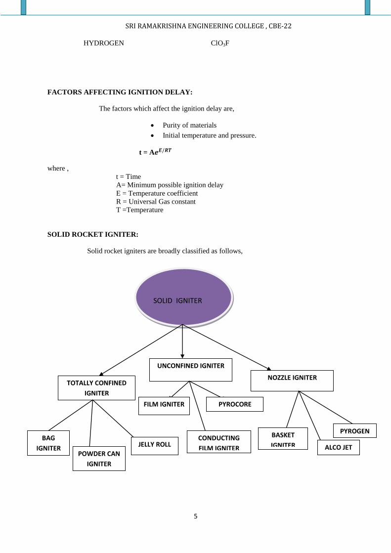
SOLID ROCKET IGNITER:
Solid rocket igniters are broadly classified as follows,
dvedgeldv
SOLID IGNITER
TOTALLY CONFINED
IGNITER
UNCONFINED IGNITER
NOZZLE IGNITER
BAG
IGNITER POWDER CAN
IGNITER
JELLY ROLL
FILM IGNITER PYROCORE
CONDUCTING
FILM IGNITER
BASKET
IGNITER ALCO JET
PYROGEN
SRI RAMAKRISHNA ENGINEERING COLLEGE , CBE-22
6
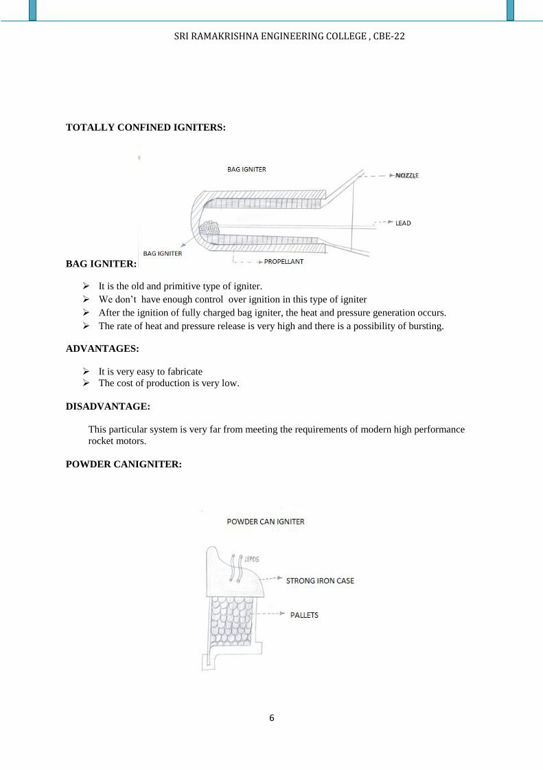
TOTALLY CONFINED IGNITERS:
BAG IGNITER:
It is the old and primitive type of igniter.
We don’t have enough control over ignition in this type of igniter
After the ignition of fully charged bag igniter, the heat and pressure generation occurs.
The rate of heat and pressure release is very high and there is a possibility of bursting.
ADVANTAGES:
It is very easy to fabricate
The cost of production is very low.
DISADVANTAGE:
This particular system is very far from meeting the requirements of modern high performance
rocket motors.
POWDER CANIGNITER:
SRI RAMAKRISHNA ENGINEERING COLLEGE , CBE-22
7
In this type of igniter pallets are used .Pallets are made up of black powder or metal oxidants
and aluminium powder. Here directional control is done but not sufficient. It is only suitable for small
rocket motors and not suitable for large rocket motors because of its erratic transient ignition
characteristics and it is rapturous.
ADVANTEGES:
Ease of fabrication and production cost is low.
DISADVANTAGES:
As the igniter is made of steel casing the weight is much heavier.
Only suitable for short range missions.
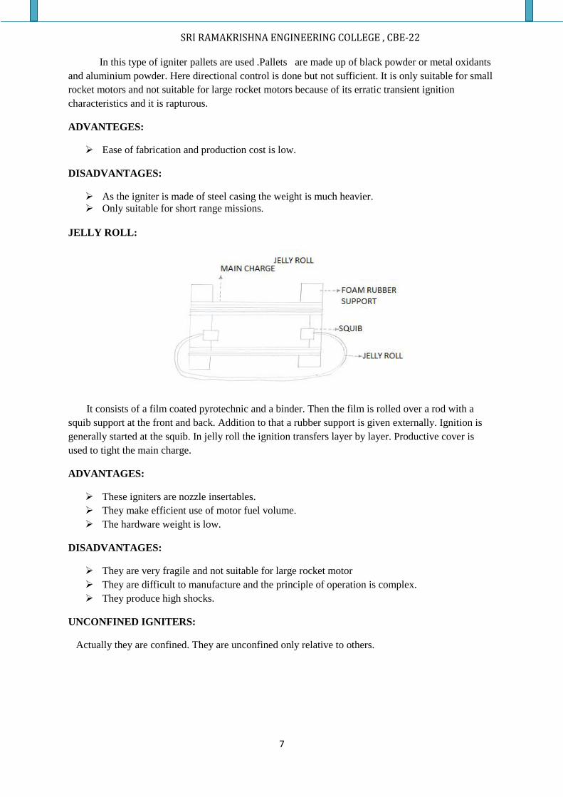
JELLY ROLL:
It consists of a film coated pyrotechnic and a binder. Then the film is rolled over a rod with a
squib support at the front and back. Addition to that a rubber support is given externally. Ignition is
generally started at the squib. In jelly roll the ignition transfers layer by layer. Productive cover is
used to tight the main charge.
ADVANTAGES:
These igniters are nozzle insertables.
They make efficient use of motor fuel volume.
The hardware weight is low.
DISADVANTAGES:
They are very fragile and not suitable for large rocket motor
They are difficult to manufacture and the principle of operation is complex.
They produce high shocks.
UNCONFINED IGNITERS:
Actually they are confined. They are unconfined only relative to others.
SRI RAMAKRISHNA ENGINEERING COLLEGE , CBE-22
8
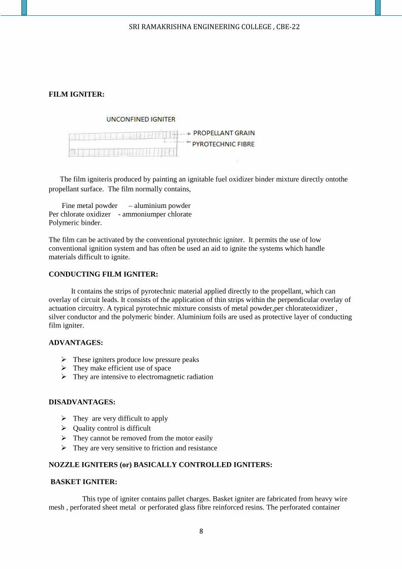
FILM IGNITER:
The film igniteris produced by painting an ignitable fuel oxidizer binder mixture directly ontothe
propellant surface. The film normally contains,
Fine metal powder – aluminium powder
Per chlorate oxidizer - ammoniumper chlorate
Polymeric binder.
The film can be activated by the conventional pyrotechnic igniter. It permits the use of low
conventional ignition system and has often be used an aid to ignite the systems which handle
materials difficult to ignite.
CONDUCTING FILM IGNITER:
It contains the strips of pyrotechnic material applied directly to the propellant, which can
overlay of circuit leads. It consists of the application of thin strips within the perpendicular overlay of
actuation circuitry. A typical pyrotechnic mixture consists of metal powder,per chlorateoxidizer ,
silver conductor and the polymeric binder. Aluminium foils are used as protective layer of conducting
film igniter.
ADVANTAGES:
These igniters produce low pressure peaks
They make efficient use of space
They are intensive to electromagnetic radiation
DISADVANTAGES:
They are very difficult to apply
Quality control is difficult
They cannot be removed from the motor easily
They are very sensitive to friction and resistance
NOZZLE IGNITERS (or) BASICALLY CONTROLLED IGNITERS:
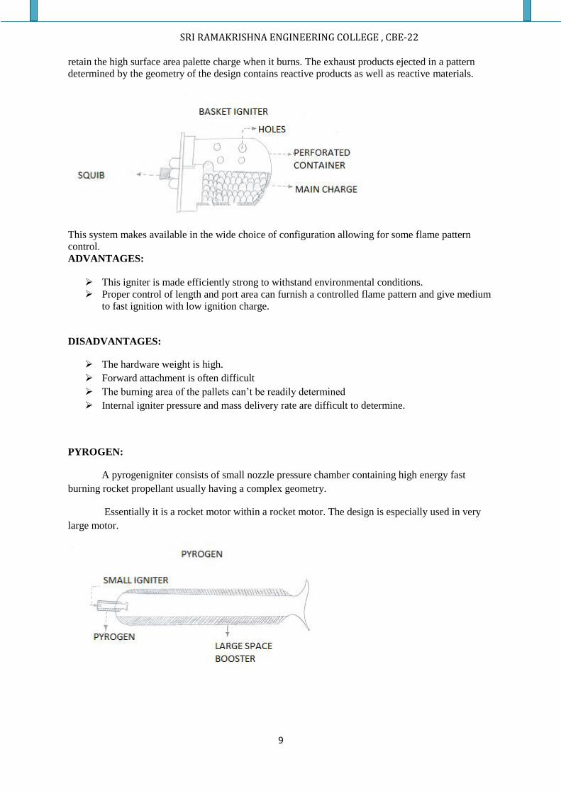
BASKET IGNITER:
This type of igniter contains pallet charges. Basket igniter are fabricated from heavy wire
mesh , perforated sheet metal or perforated glass fibre reinforced resins. The perforated container
SRI RAMAKRISHNA ENGINEERING COLLEGE , CBE-22
9
retain the high surface area palette charge when it burns. The exhaust products ejected in a pattern
determined by the geometry of the design contains reactive products as well as reactive materials.
This system makes available in the wide choice of configuration allowing for some flame pattern
control.
ADVANTAGES:
This igniter is made efficiently strong to withstand environmental conditions.
Proper control of length and port area can furnish a controlled flame pattern and give medium
to fast ignition with low ignition charge.
DISADVANTAGES:
The hardware weight is high.
Forward attachment is often difficult
The burning area of the pallets can’t be readily determined
Internal igniter pressure and mass delivery rate are difficult to determine.
PYROGEN:
A pyrogenigniter consists of small nozzle pressure chamber containing high energy fast
burning rocket propellant usually having a complex geometry.
Essentially it is a rocket motor within a rocket motor. The design is especially used in very
large motor.
SRI RAMAKRISHNA ENGINEERING COLLEGE , CBE-22
10
ADVANTAGES:
The igniters have little or no shocks.
They eliminate the handling of large amounts of relatively hazardous metal oxide
charges.
They are adoptable to either head end or launcher mount applications.
DISADVANTAGES:
The pyrogen must itself have an igniter and it’s therefore depends upon the principle used to
ignite.
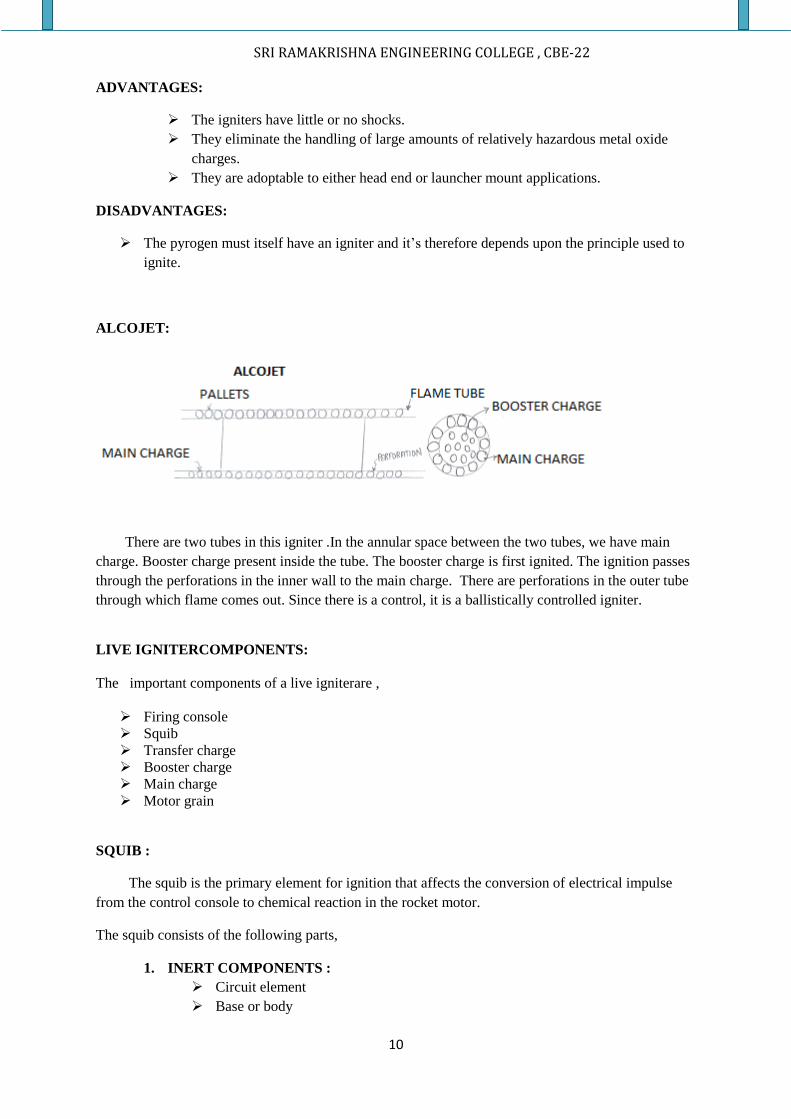
ALCOJET:
There are two tubes in this igniter .In the annular space between the two tubes, we have main
charge. Booster charge present inside the tube. The booster charge is first ignited. The ignition passes
through the perforations in the inner wall to the main charge. There are perforations in the outer tube
through which flame comes out. Since there is a control, it is a ballistically controlled igniter.
LIVE IGNITERCOMPONENTS:
The important components of a live igniterare ,
Firing console
Squib
Transfer charge
Booster charge
Main charge
Motor grain
SQUIB :
The squib is the primary element for ignition that affects the conversion of electrical impulse
from the control console to chemical reaction in the rocket motor.
The squib consists of the following parts,
1. INERT COMPONENTS :
Circuit element
Base or body
SRI RAMAKRISHNA ENGINEERING COLLEGE , CBE-22
11
Insulation
Metal case
2. ACTIVE COMPONENTS :
Prime charge
Booster charge
Main charge
CHARACTERISTICS OF A SQUIB:
1. A functioning time curve
2. Pressure output characteristics
3. Thermal output characteristics
4. Auto ignition characteristics
5. Static sensitivity characteristics
6. Shock and mechanical sensitivity characteristics
IGNITER DESIGNCONSIDERATION :
The data to be considered while designing an igniterare,
The pyrotechnic material data
Propellant ignitability data
Rocket motor data
Back up data (previous test firing data).
IGNITABILITY BOMB:
The ignitability bomb is a device used to determine the relative ignitability of the propellants at
various pressures under the direct fire of ignition materials.
INJECTORS :
An injector or ejector is a system of admitting the fuel into the combustion engine. Its function is
similar to a carburettor.
PRIMARY DIFFERENCE BETWEEN A CARBURATOR AND AN INJECTOR:
In an injector the fuel injection atomizes the fuel by forcibly pumping it through a small nozzle under
high pressure while a carburettor relies on suction created by intake air rushing through a venturi to
draw the fuel into the airstream.
FUNCTION OF AN INJECTOR:
The injectors are mainly used to meter the flow of the liquid propellant to the combustion
chamber which causes the liquids to be broken into small droplets. This process is known as
atomization. It also helps to distribute and mix the propellant in a correctly proportionate mixture of
fuel and oxidizer, which results in uniform propellant mass flow.
INJECTION HOLE PATTERNS:
The injectionhole pattern on the face of the injector is closely related to the internal manifolds or feed
passages. These hole patterns provides the distribution of propellant from the injector inlet to all the
injection holes.
SRI RAMAKRISHNA ENGINEERING COLLEGE , CBE-22
12
A large complex manifold volume allows low passage velocities and good distribution of flow
over the chamber.A small manifold volume allows for a light weight injector and reduces the amount
of “dribble” after the main walls are shut.
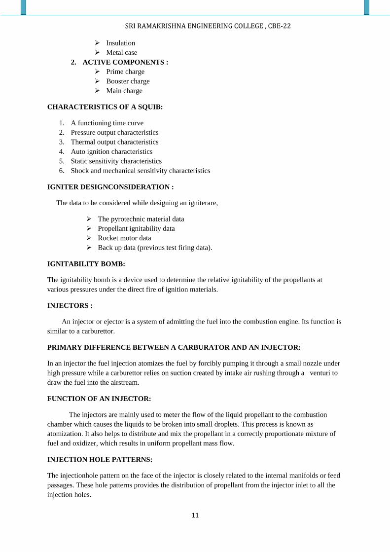
TYPES OF INJECTORS:
IMPIN
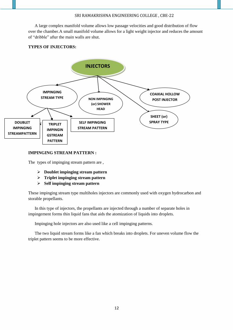
IMPINGING STREAM PATTERN :
The types of impinging stream pattern are ,
Doublet impinging stream pattern
Triplet impinging stream pattern
Self impinging stream pattern
These impinging stream type multiholes injectors are commonly used with oxygen hydrocarbon and
storable propellants.
In this type of injectors, the propellants are injected through a number of separate holes in
impingement forms thin liquid fans that aids the atomization of liquids into droplets.
Impinging hole injectors are also used like a cell impinging patterns.
The two liquid stream forms like a fan which breaks into droplets. For uneven volume flow the
triplet pattern seems to be more effective.
INJECTORS
IMPINGING
STREAM TYPE
DOUBLET
IMPINGING
STREAMPATTERN
TRIPLET
IMPINGIN
GSTREAM
PATTERN
STREAM
SELF IMPINGING
STREAM PATTERN
NON IMPINGING
(or) SHOWER
HEAD
SHEET (or)
SPRAY TYPE
COAXIAL HOLLOW
POST INJECTOR
SRI RAMAKRISHNA ENGINEERING COLLEGE , CBE-22
13
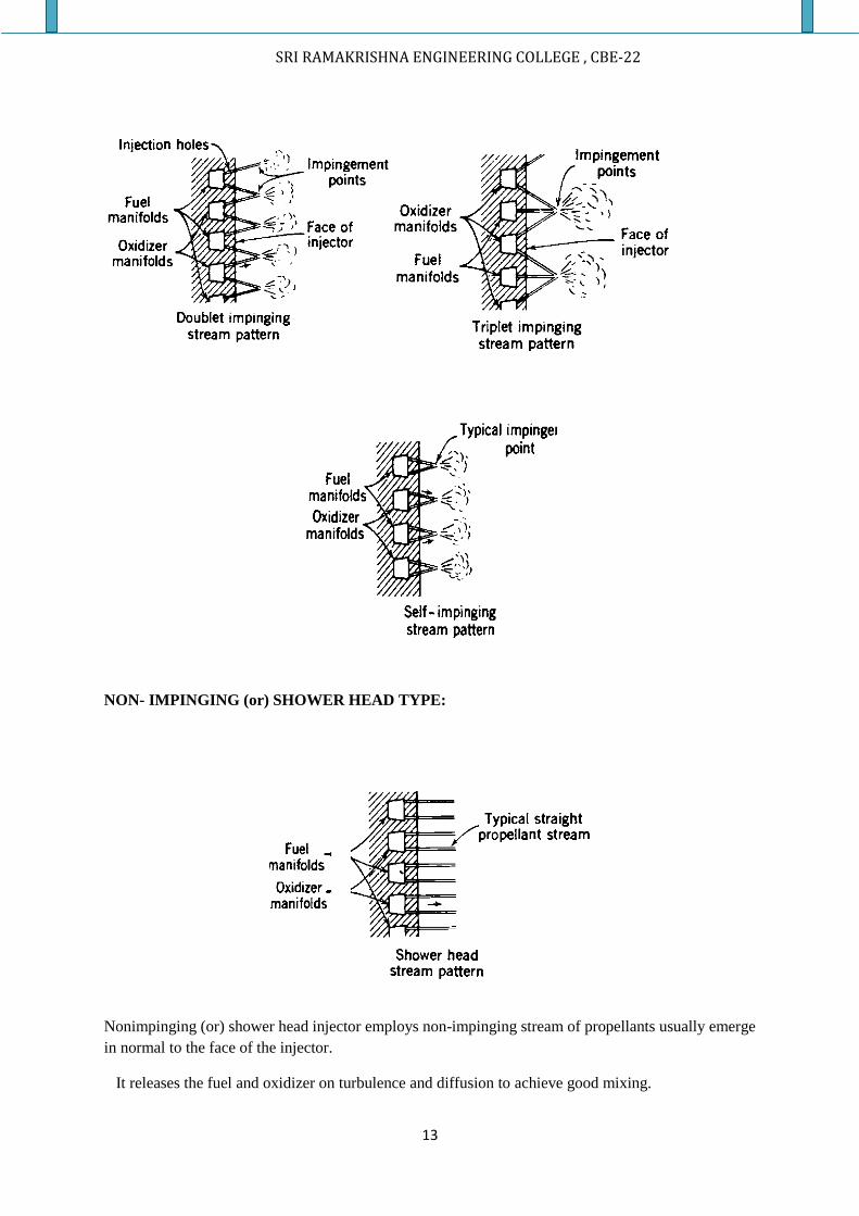
NON- IMPINGING (or) SHOWER HEAD TYPE:
Nonimpinging (or) shower head injector employs non-impinging stream of propellants usually emerge
in normal to the face of the injector.
It releases the fuel and oxidizer on turbulence and diffusion to achieve good mixing.
SRI RAMAKRISHNA ENGINEERING COLLEGE , CBE-22
14
This type of injectors is not used now, because it requires a large chamber volume for good
combustion.
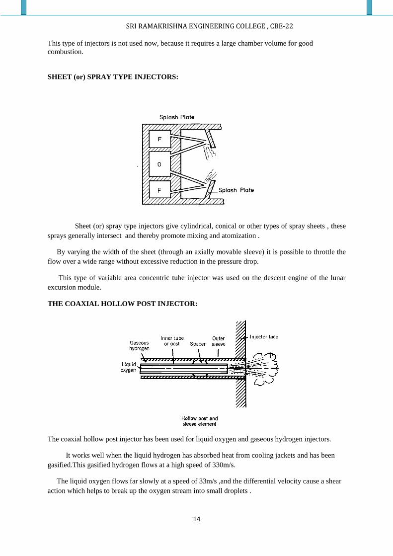
SHEET (or) SPRAY TYPE INJECTORS:
Sheet (or) spray type injectors give cylindrical, conical or other types of spray sheets , these
sprays generally intersect and thereby promote mixing and atomization .
By varying the width of the sheet (through an axially movable sleeve) it is possible to throttle the
flow over a wide range without excessive reduction in the pressure drop.
This type of variable area concentric tube injector was used on the descent engine of the lunar
excursion module.
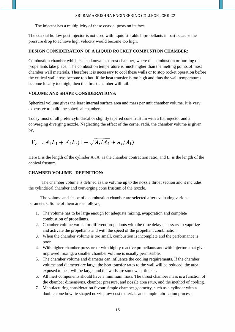
THE COAXIAL HOLLOW POST INJECTOR:
The coaxial hollow post injector has been used for liquid oxygen and gaseous hydrogen injectors.
It works well when the liquid hydrogen has absorbed heat from cooling jackets and has been
gasified.This gasified hydrogen flows at a high speed of 330m/s.
The liquid oxygen flows far slowly at a speed of 33m/s ,and the differential velocity cause a shear
action which helps to break up the oxygen stream into small droplets .
SRI RAMAKRISHNA ENGINEERING COLLEGE , CBE-22
15
The injector has a multiplicity of these coaxial posts on its face .
The coaxial hollow post injector is not used with liquid storable bipropellants in part because the
pressure drop to achieve high velocity would become too high.
DESIGN CONSIDERATION OF A LIQUID ROCKET COMBUSTION CHAMBER:
Combustion chamber which is also known as thrust chamber, where the combustion or burning of
propellants take place. The combustion temperature is much higher than the melting points of most
chamber wall materials. Therefore it is necessary to cool these walls or to stop rocket operation before
the critical wall areas become too hot. If the heat transfer is too high and thus the wall temperatures
become locally too high, then the thrust chamber will fail.
VOLUME AND SHAPE CONSIDERATIONS:
Spherical volume gives the least internal surface area and mass per unit chamber volume. It is very
expensive to build the spherical chambers.
Today most of all prefer cylindrical or slightly tapered cone frustum with a flat injector and a
converging diverging nozzle. Neglecting the effect of the corner radii, the chamber volume is given
by,
Here L is the length of the cylinder AL/At is the chamber contraction ratio, and Lc is the length of the
conical frustum.
CHAMBER VOLUME - DEFINITION:
The chamber volume is defined as the volume up to the nozzle throat section and it includes
the cylindrical chamber and converging cone frustum of the nozzle.
The volume and shape of a combustion chamber are selected after evaluating various
parameters. Some of them are as follows,
1. The volume has to be large enough for adequate mixing, evaporation and complete
combustion of propellants.
2. Chamber volume varies for different propellants with the time delay necessary to vaporize
and activate the propellants and with the speed of the propellant combination.
3. When the chamber volume is too small, combustion is incomplete and the performance is
poor.
4. With higher chamber pressure or with highly reactive propellants and with injectors that give
improved mixing, a smaller chamber volume is usually permissible.
5. The chamber volume and diameter can influence the cooling requirements. If the chamber
volume and diameter are large, the heat transfer rates to the wall will be reduced, the area
exposed to heat will be large, and the walls are somewhat thicker.
6. All inert components should have a minimum mass. The thrust chamber mass is a function of
the chamber dimensions, chamber pressure, and nozzle area ratio, and the method of cooling.
7. Manufacturing consideration favour simple chamber geometry, such as a cylinder with a
double cone bow tie shaped nozzle, low cost materials and simple fabrication process.
SRI RAMAKRISHNA ENGINEERING COLLEGE , CBE-22
16
8. In some applications the length of the chamber and the nozzle relate directly to the overall
length of the vehicle.A large diameter but short chamber can allow a somewhat shorter
vehicle with a lower structural inert vehicle mass.
9. The gas pressure drop for accelerating the combustion products within the chamber should be
a minimum; any pressure reduction at the nozzle inlet reduces the exhaust velocity and the
performance of the vehicle. These losses become appreciable when the chamber volume less
than three times the throat area.
10. For the same thrust the combustion volume and the nozzle throat area become smaller as the
operating chamber pressure is increased. This means that the chamber length and the nozzle
length also decrease with increasing chamber pressure, the performance will go up with
chamber pressure.
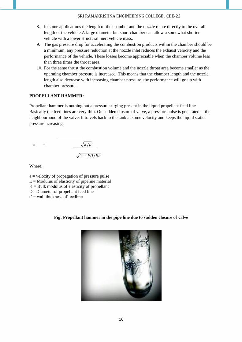
PROPELLANT HAMMER:
Propellant hammer is nothing but a pressure surging present in the liquid propellant feed line.
Basically the feed lines are very thin. On sudden closure of valve, a pressure pulse is generated at the
neighbourhood of the valve. It travels back to the tank at some velocity and keeps the liquid static
pressureincreasing.
a = 𝑘/𝜌
1 + 𝑘𝐷/𝐸𝑡′
Where,
a = velocity of propagation of pressure pulse
E = Modulus of elasticity of pipeline material
K = Bulk modulus of elasticity of propellant
D =Diameter of propellant feed line
t’ = wall thickness of feedline
Fig: Propellant hammer in the pipe line due to sudden closure of valve
SRI RAMAKRISHNA ENGINEERING COLLEGE , CBE-22
17
changes in the momentum of the fluid in the feed line is caused by the opening or closing of valves in
the line result in pressure peaks analogous to the propellant hammer ,such situation occurs during the
rocket engine start , during the initial bleed of the rocket engine or rocket engine set down . This
situation fall under two categories.
1. Valve opening
2. Valve closure
In case of valve closure ,i.e ,
tc=valve closure time
a = velocity of propagation of pressure pulse
2L/a ≥tc ; for fast valve closure
2L/a <tc ; for slow valve closure
TANK OUTLET DESIGN CONSIDERATION:
Before designing the tank outlet the designer have to solve three main problems. They are,
1. Cavitation
2. Dropout
3. Vortexing
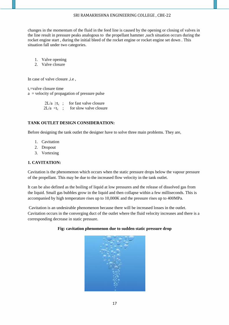
1. CAVITATION:
Cavitation is the phenomenon which occurs when the static pressure drops below the vapour pressure
of the propellant. This may be due to the increased flow velocity in the tank outlet.
It can be also defined as the boiling of liquid at low pressures and the release of dissolved gas from
the liquid. Small gas bubbles grow in the liquid and then collapse within a few milliseconds. This is
accompanied by high temperature rises up to 10,000K and the pressure rises up to 400MPa.
Cavitation is an undesirable phenomenon because there will be increased losses in the outlet.
Cavitation occurs in the converging duct of the outlet where the fluid velocity increases and there is a
corresponding decrease in static pressure.
Fig: cavitation phenomenon due to sudden static pressure drop
SRI RAMAKRISHNA ENGINEERING COLLEGE , CBE-22
18
SOLUTION FOR CAVITATION:
Cavitation problem can be avoided by contouring the outlet, so that the static pressure is constant
throughout the outlet. Cavitation can also suppress by avoiding high flow velocities or by using high
fluid pressures or by combination of both. The high fluid pressures in the turbo pumps are achieved
by high tank pressures, possibly in combination with booster pumps.
2. LIQUID DROP OUT:
Liquid drop out is an undesirable phenomenon in case of liquid rocket engines. Liquid dropout is
basically a depression in the liquid surface at centre of the flow lines, which occurs in higher vertical
velocity along the centre line of the outlet than along the wall exit.
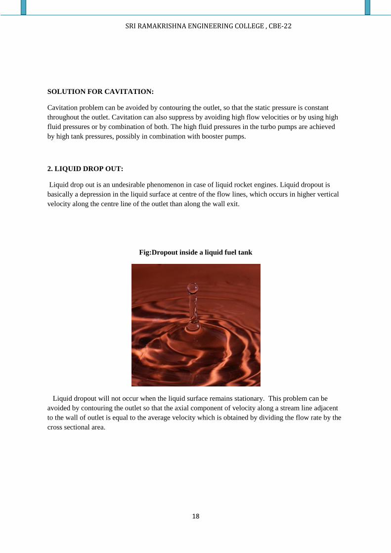
Fig:Dropout inside a liquid fuel tank
Liquid dropout will not occur when the liquid surface remains stationary. This problem can be
avoided by contouring the outlet so that the axial component of velocity along a stream line adjacent
to the wall of outlet is equal to the average velocity which is obtained by dividing the flow rate by the
cross sectional area.
SRI RAMAKRISHNA ENGINEERING COLLEGE , CBE-22
19
3. VORTEXING:
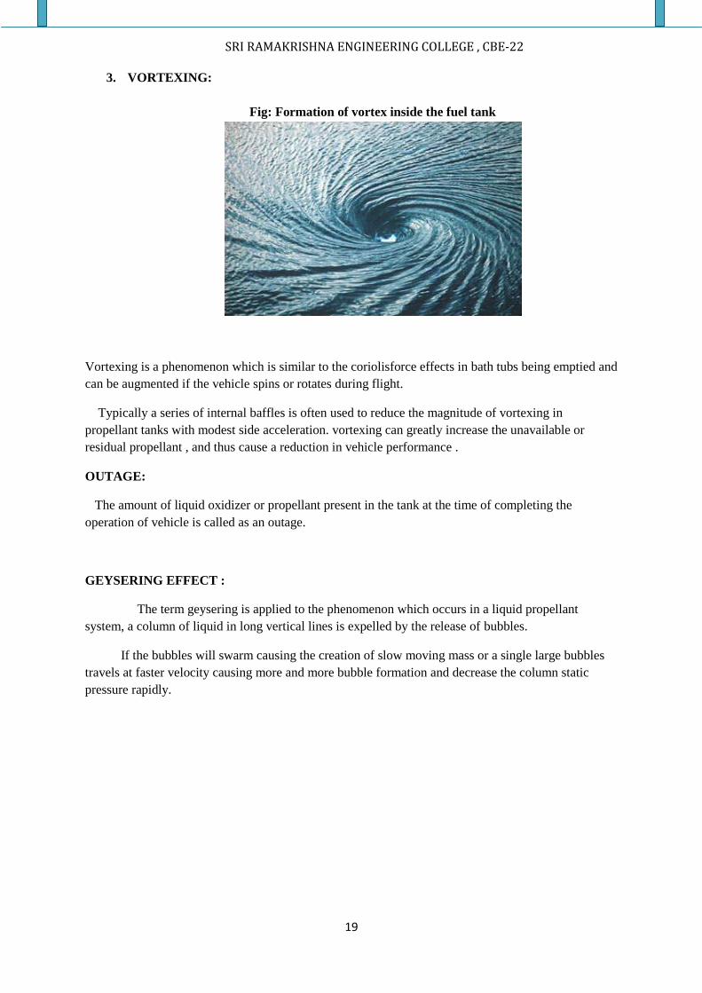
Fig: Formation of vortex inside the fuel tank
Vortexing is a phenomenon which is similar to the coriolisforce effects in bath tubs being emptied and
can be augmented if the vehicle spins or rotates during flight.
Typically a series of internal baffles is often used to reduce the magnitude of vortexing in
propellant tanks with modest side acceleration. vortexing can greatly increase the unavailable or
residual propellant , and thus cause a reduction in vehicle performance .
OUTAGE:
The amount of liquid oxidizer or propellant present in the tank at the time of completing the
operation of vehicle is called as an outage.
GEYSERING EFFECT :
The term geysering is applied to the phenomenon which occurs in a liquid propellant
system, a column of liquid in long vertical lines is expelled by the release of bubbles.
If the bubbles will swarm causing the creation of slow moving mass or a single large bubbles
travels at faster velocity causing more and more bubble formation and decrease the column static
pressure rapidly.
SRI RAMAKRISHNA ENGINEERING COLLEGE , CBE-22
20
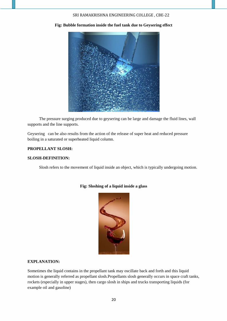
Fig: Bubble formation inside the fuel tank due to Geysering effect
The pressure surging produced due to geysering can be large and damage the fluid lines, wall
supports and the line supports.
Geysering can be also results from the action of the release of super heat and reduced pressure
boiling in a saturated or superheated liquid column.
PROPELLANT SLOSH:
SLOSH-DEFINITION:
Slosh refers to the movement of liquid inside an object, which is typically undergoing motion.
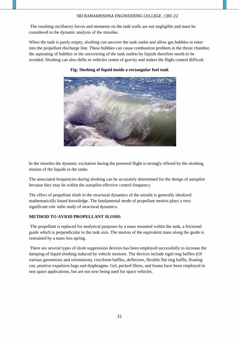
Fig: Sloshing of a liquid inside a glass
EXPLANATION:
Sometimes the liquid contains in the propellant tank may oscillate back and forth and this liquid
motion is generally referred as propellant slosh.Propellants slosh generally occurs in space craft tanks,
rockets (especially in upper stages), then cargo slosh in ships and trucks transporting liquids (for
example oil and gasoline)
SRI RAMAKRISHNA ENGINEERING COLLEGE , CBE-22
21
The resulting oscillatory forces and moments on the tank walls are not negligible and must be
considered in the dynamic analysis of the missiles.
When the tank is partly empty, sloshing can uncover the tank outlet and allow gas bubbles to enter
into the propellant discharge line. These bubbles can cause combustion problem in the thrust chamber,
the aspirating of bubbles or the uncovering of the tank outlets by liquids therefore needs to be
avoided. Sloshing can also shifts in vehicles centre of gravity and makes the flight control difficult.
Fig: Sloshing of liquid inside a rectangular fuel tank
In the missiles the dynamic excitation during the powered flight is strongly offered by the sloshing
motion of the liquids in the tanks.
The associated frequencies during sloshing can be accurately determined for the design of autopilot
because they may be within the autopilot effective control frequency.
The effect of propellant slosh in the structural dynamics of the missile is generally idealized
mathematically based knowledge. The fundamental mode of propellant motion plays a very
significant role inthe study of structural dynamics.
METHOD TO AVIOD PROPELLANT SLOSH:
The propellant is replaced for analytical purposes by a mass mounted within the tank, a frictional
guide which is perpendicular to the tank axis. The motion of the equivalent mass along the guide is
restrained by a mass less spring.
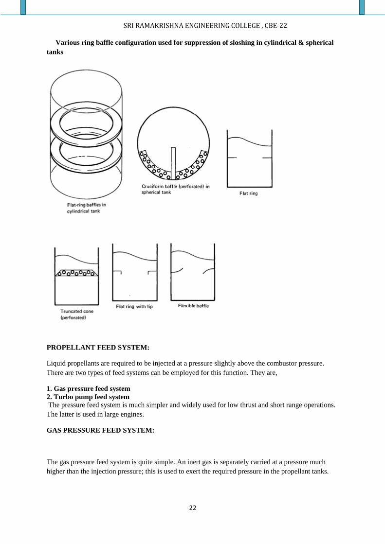
There are several types of slosh suppression devices has been employed successfully to increase the
damping of liquid sloshing induced by vehicle motions. The devices include rigid ring baffles (Of
various geometries and orientation), cruciform baffles, deflectors, flexible flat ring baffle, floating
can, positive expulsion bags and diaphragms. Gel, packed fibres, and foams have been employed in
non space applications, but are not now being used for space vehicles.
SRI RAMAKRISHNA ENGINEERING COLLEGE , CBE-22
22
Various ring baffle configuration used for suppression of sloshing in cylindrical & spherical
tanks
PROPELLANT FEED SYSTEM:
Liquid propellants are required to be injected at a pressure slightly above the combustor pressure.
There are two types of feed systems can be employed for this function. They are,
1. Gas pressure feed system
2. Turbo pump feed system
The pressure feed system is much simpler and widely used for low thrust and short range operations.
The latter is used in large engines.
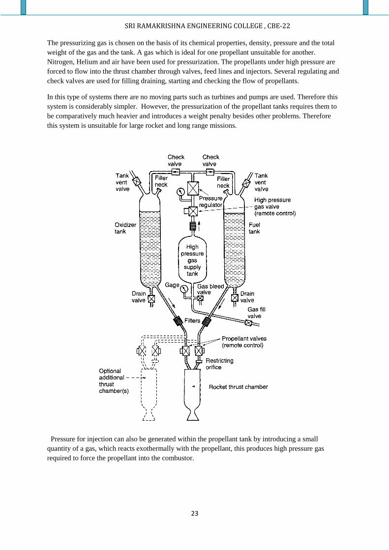
GAS PRESSURE FEED SYSTEM:
The gas pressure feed system is quite simple. An inert gas is separately carried at a pressure much
higher than the injection pressure; this is used to exert the required pressure in the propellant tanks.
SRI RAMAKRISHNA ENGINEERING COLLEGE , CBE-22
23
The pressurizing gas is chosen on the basis of its chemical properties, density, pressure and the total
weight of the gas and the tank. A gas which is ideal for one propellant unsuitable for another.
Nitrogen, Helium and air have been used for pressurization. The propellants under high pressure are
forced to flow into the thrust chamber through valves, feed lines and injectors. Several regulating and
check valves are used for filling draining, starting and checking the flow of propellants.
In this type of systems there are no moving parts such as turbines and pumps are used. Therefore this
system is considerably simpler. However, the pressurization of the propellant tanks requires them to
be comparatively much heavier and introduces a weight penalty besides other problems. Therefore
this system is unsuitable for large rocket and long range missions.
Pressure for injection can also be generated within the propellant tank by introducing a small
quantity of a gas, which reacts exothermally with the propellant, this produces high pressure gas
required to force the propellant into the combustor.
SRI RAMAKRISHNA ENGINEERING COLLEGE , CBE-22
24
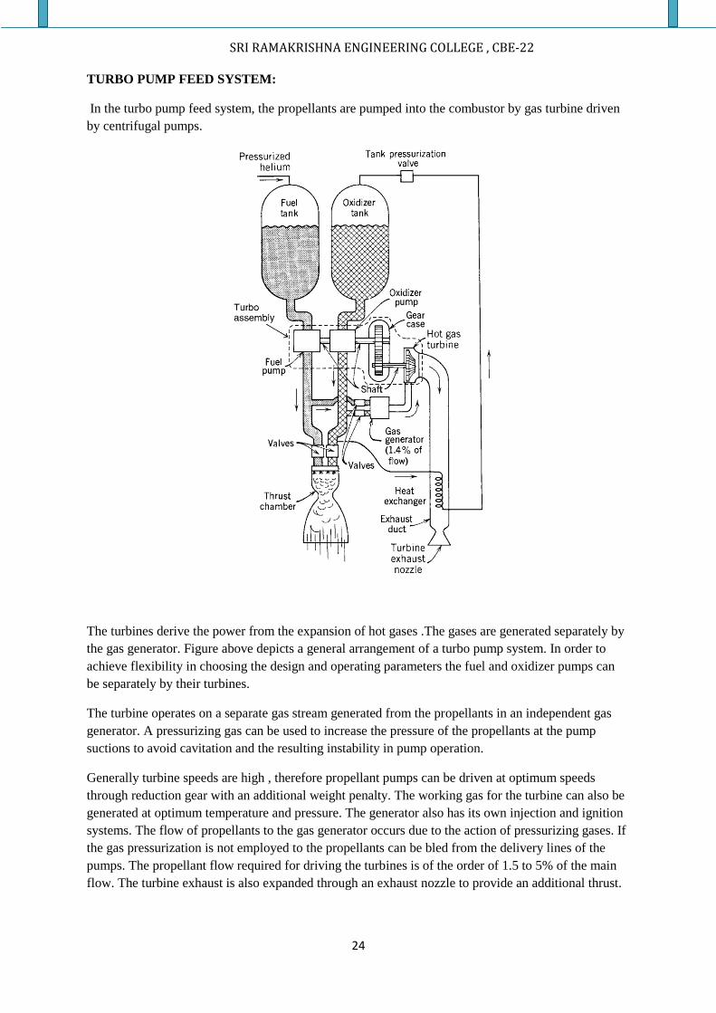
TURBO PUMP FEED SYSTEM:
In the turbo pump feed system, the propellants are pumped into the combustor by gas turbine driven
by centrifugal pumps.
The turbines derive the power from the expansion of hot gases .The gases are generated separately by
the gas generator. Figure above depicts a general arrangement of a turbo pump system. In order to
achieve flexibility in choosing the design and operating parameters the fuel and oxidizer pumps can
be separately by their turbines.
The turbine operates on a separate gas stream generated from the propellants in an independent gas
generator. A pressurizing gas can be used to increase the pressure of the propellants at the pump
suctions to avoid cavitation and the resulting instability in pump operation.
Generally turbine speeds are high , therefore propellant pumps can be driven at optimum speeds
through reduction gear with an additional weight penalty. The working gas for the turbine can also be
generated at optimum temperature and pressure. The generator also has its own injection and ignition
systems. The flow of propellants to the gas generator occurs due to the action of pressurizing gases. If
the gas pressurization is not employed to the propellants can be bled from the delivery lines of the
pumps. The propellant flow required for driving the turbines is of the order of 1.5 to 5% of the main
flow. The turbine exhaust is also expanded through an exhaust nozzle to provide an additional thrust.
SRI RAMAKRISHNA ENGINEERING COLLEGE , CBE-22
25
An auxiliary power unit is also needed in a rocket engine. A single turbine can develop sufficient
power to drive the propellant pumps as well as the electric generator. Besides working on high energy
gases bled from the main thrust chamber or combustor it can also employ its own combustor with a
gas pressure feed system. An alternative method which is comparatively simpler is to generate the
working gases by burning solid propellants in a manner similar to the solid propellant rocket.
The turbines and pumps for rocket applications are designed to meet some special requirements.
There are enormous temperature differences with a turbine inlet at a high temperature of the
propellants are highly reactive. Therefore the sealing arrangement in propellant pumps should be
perfect and resistant to corrosion.
Both positive displacement and turbo pumps can be used for delivering propellants from the tank to
the combustion chamber. However centrifugal pumps are widely used.
VALVES AND PIPE LINES:
VALVES:
Valves control the flows of liquids and gases and pipes conduct these fluids to the intended
components. There are no rocket engines without them. There are many different types of valves. All
have to be reliable, light weight, leak proof, and must withstand intensive vibrations and very loud
noises.
With many of these valves, any leakage or valve failure can cause a failure of the rocket unit
itself. Allvalves are tested for two qualities prior to installation; they are tested for leaks - through the
seat and alsothrough the glands--and for functional soundness or performance.
The propellant valves in high thrust units handle relatively large flows at high service pressures.
Therefore, the forces necessary to actuate the valves are large. Hydraulic or pneumatic pressure,
controlled bypilot valves, operates the larger valves. These
Classification of Valves Used in Liquid Propellant Rocket Engines
1. Fluid valve:
For carrying fuel, oxidizer,cold pressurized gas, and hot turbine gas this type of valve is used.
2. Application or Use:
The valves which are mainly used for propellant control are
Thrust chamber valve (dual or single),bleed valve, drain valve, filling valves, by-pass valve,
preliminary stage flow valve, pilot valve, safety valve; overboard dump valve, regulator
valve, gas generator control valve, sequence control valve.
3. Mode of Actuation:
The valves are operated by different means of actuation. The different modes are,
Automatically operated (by solenoid, pilot valve, trip mechanism, pyrotechnic, etc.)
Manually operated
Pressure-operated by air, gas, propellant, or hydraulic fluid (e.g., check valve, tank
vent valve, pressure regulator, relief valve)
4. The flow magnitude determines the size of the valve.
SRI RAMAKRISHNA ENGINEERING COLLEGE , CBE-22
26
5. Valve Types:
Normally open, normally closed, normally partly open, two-way, three-way,
with/without valve position feedback, ball valve, gate valve, butterfly type,spring loaded valve.
PIPES (or) LINES:
The various fluids in a rocket engine are conveyed by pipes or lines, usually made of metal
and are joined byfittings or welds. Their design must provide thermal expansion and provide support
to minimize vibrationeffects. For gimballed thrust chambers it is necessary to provide flexibility in the
piping to allow the thrust axis tobe rotated through a small angle, typically +3 to 10 °. This flexibility
is provided by flexible pipe joints and or byallowing pipes to deflect when using two or more right-
angle turns in the lines. Sudden closing of valves can cause propellant hammer in the pipelines,
leading to unexpected pressure rises which can be destructive to propellant system components. The
friction of the pipe and the branching ofpipelines reduce this maximum pressure.
Propellant hammer can also occur when admitting the initial flow of high-pressure propellant
intoevacuated pipes. The pipes are under vacuum to remove air and prevent the forming of gas
bubbles in the propellant flow, which can cause combustion problems.
COOLING OF THRUST CHAMBER:
NEED FOR COOLING:
The primary objective of cooling is to prevent the chamber and nozzle walls from becoming too hot,
so they will no longer able to withstand the imposed loads and stresses, thus causing the chamber or
nozzle to fail. Most materials lose strength and become weaker as temperature is increased. Cooling
thus reduces the wall temperatures to an acceptable limit.
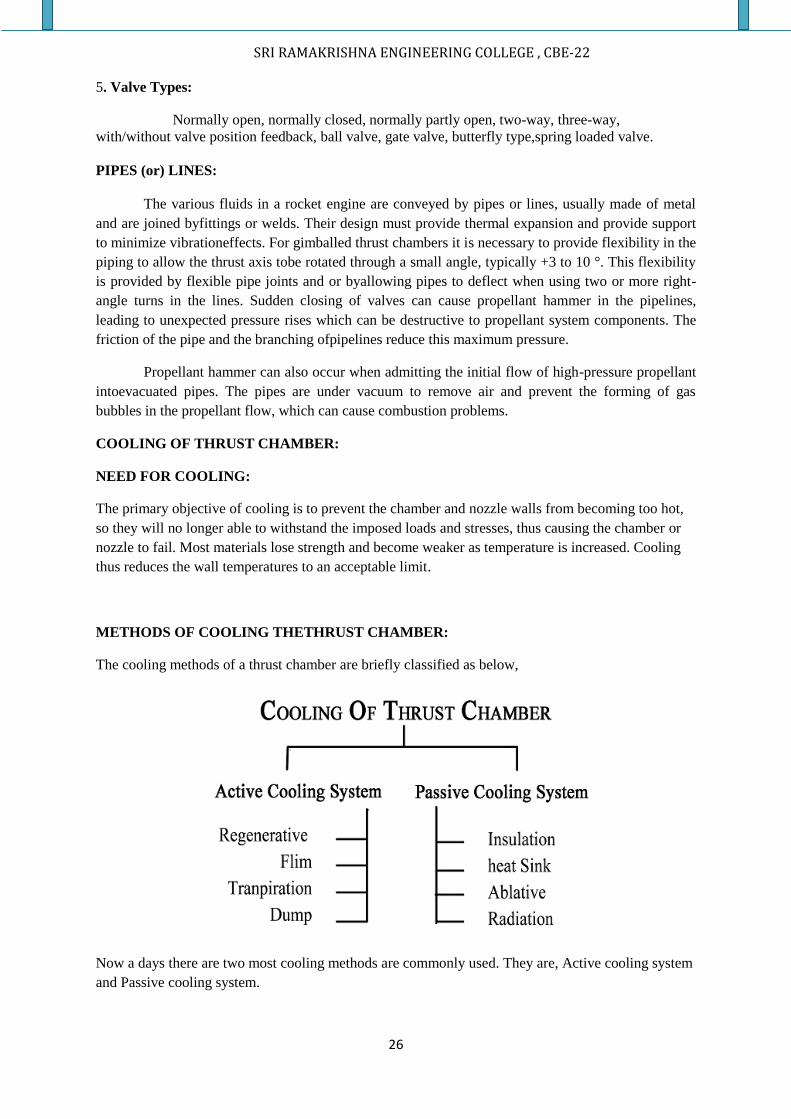
METHODS OF COOLING THETHRUST CHAMBER:
The cooling methods of a thrust chamber are briefly classified as below,
Now a days there are two most cooling methods are commonly used. They are, Active cooling system
and Passive cooling system.
SRI RAMAKRISHNA ENGINEERING COLLEGE , CBE-22
27
ACTIVE COOLING SYSTEM:
In liquid rocket motor, the nozzle and chamber walls are exposed to hot combustion
products. Usually these walls are provided with ducts
The four most important active cooling methods are,
1. Regenerative cooling
2. Film cooling
3. Transpiration cooling
4. Dump cooling
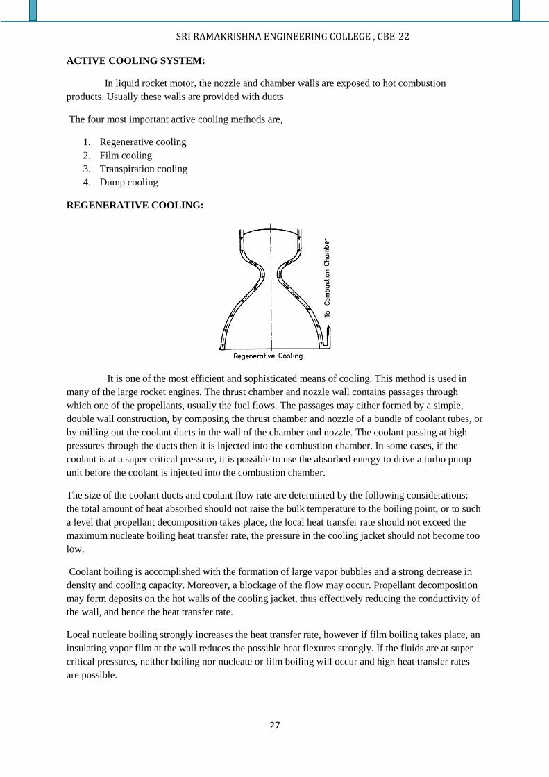
REGENERATIVE COOLING:
It is one of the most efficient and sophisticated means of cooling. This method is used in
many of the large rocket engines. The thrust chamber and nozzle wall contains passages through
which one of the propellants, usually the fuel flows. The passages may either formed by a simple,
double wall construction, by composing the thrust chamber and nozzle of a bundle of coolant tubes, or
by milling out the coolant ducts in the wall of the chamber and nozzle. The coolant passing at high
pressures through the ducts then it is injected into the combustion chamber. In some cases, if the
coolant is at a super critical pressure, it is possible to use the absorbed energy to drive a turbo pump
unit before the coolant is injected into the combustion chamber.
The size of the coolant ducts and coolant flow rate are determined by the following considerations:
the total amount of heat absorbed should not raise the bulk temperature to the boiling point, or to such
a level that propellant decomposition takes place, the local heat transfer rate should not exceed the
maximum nucleate boiling heat transfer rate, the pressure in the cooling jacket should not become too
low.
Coolant boiling is accomplished with the formation of large vapor bubbles and a strong decrease in
density and cooling capacity. Moreover, a blockage of the flow may occur. Propellant decomposition
may form deposits on the hot walls of the cooling jacket, thus effectively reducing the conductivity of
the wall, and hence the heat transfer rate.
Local nucleate boiling strongly increases the heat transfer rate, however if film boiling takes place, an
insulating vapor film at the wall reduces the possible heat flexures strongly. If the fluids are at super
critical pressures, neither boiling nor nucleate or film boiling will occur and high heat transfer rates
are possible.
SRI RAMAKRISHNA ENGINEERING COLLEGE , CBE-22
28
Regenerative cooling is very effective as nearly all heat energy that has transferred to the wall is fed
back into the thrust chamber and hence is available for propulsion. This requires a complicated
construction and there is a large pressure drop along the coolant jacket, hence needed very high pump
pressure. Moreover, some propellants only allow low wall temperatures otherwise decomposition may
take place.
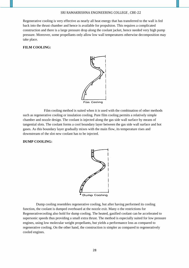
FILM COOLING:
Film cooling method is suited when it is used with the combination of other methods
such as regenerative cooling or insulation cooling. Pure film cooling permits a relatively simple
chamber and nozzle design. The coolant is injected along the gas side wall surface by means of
tangential slots. The coolant forms a cool boundary layer between the gas side wall surface and hot
gases. As this boundary layer gradually mixes with the main flow, its temperature rises and
downstream of the slot new coolant has to be injected.
DUMP COOLING:
Dump cooling resembles regenerative cooling, but after having performed its cooling
function, the coolant is dumped overboard at the nozzle exit. Many o the restrictions for
Regenerativecooling also hold for dump cooling. The heated, gasified coolant can be accelerated to
supersonic speeds thus providing a small extra thrust. The method is especially suited for low pressure
engines, using low molecular weight propellants, but yields a performance loss as compared to
regenerative cooling. On the other hand, the construction is simpler as compared to regeneratively
cooled engines.
SRI RAMAKRISHNA ENGINEERING COLLEGE , CBE-22
29
PASSIVE COOLING SYSTEMS:
Among these systems, the most important ones are: insulation cooling, heat sink cooling,
ablative cooling and radiation cooling.
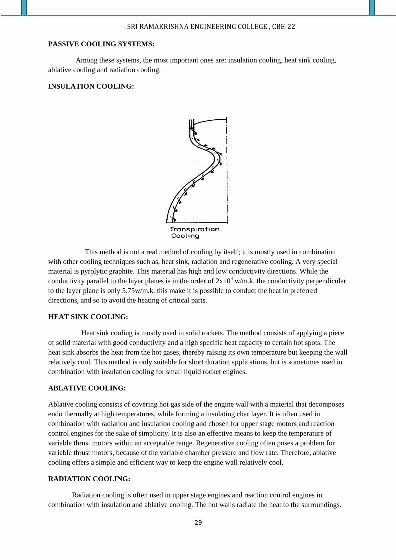
INSULATION COOLING:
This method is not a real method of cooling by itself; it is mostly used in combination
with other cooling techniques such as, heat sink, radiation and regenerative cooling. A very special
material is pyrolytic graphite. This material has high and low conductivity directions. While the
conductivity parallel to the layer planes is in the order of 2x10³ w/m.k, the conductivity perpendicular
to the layer plane is only 5.75w/m.k. this make it is possible to conduct the heat in preferred
directions, and so to avoid the heating of critical parts.
HEAT SINK COOLING:
Heat sink cooling is mostly used in solid rockets. The method consists of applying a piece
of solid material with good conductivity and a high specific heat capacity to certain hot spots. The
heat sink absorbs the heat from the hot gases, thereby raising its own temperature but keeping the wall
relatively cool. This method is only suitable for short duration applications, but is sometimes used in
combination with insulation cooling for small liquid rocket engines.
ABLATIVE COOLING:
Ablative cooling consists of covering hot gas side of the engine wall with a material that decomposes
endo thermally at high temperatures, while forming a insulating char layer. It is often used in
combination with radiation and insulation cooling and chosen for upper stage motors and reaction
control engines for the sake of simplicity. It is also an effective means to keep the temperature of
variable thrust motors within an acceptable range. Regenerative cooling often poses a problem for
variable thrust motors, because of the variable chamber pressure and flow rate. Therefore, ablative
cooling offers a simple and efficient way to keep the engine wall relatively cool.
RADIATION COOLING:
Radiation cooling is often used in upper stage engines and reaction control engines in
combination with insulation and ablative cooling. The hot walls radiate the heat to the surroundings.
SRI RAMAKRISHNA ENGINEERING COLLEGE , CBE-22
30
As the radiative heat flux is proportional to T4, the material temperature must be high to obtain a large
radiative heat flux.
Refractory metals, such as molybdenum, niobium can withstand high temperature without losing
their strength. Some refractory metals easily react with the combustion products. As the melting point
of their oxides or compounds often is much lower than that of the metals, coatings have to be applied
on many cases. The refractory alloys based on titanium, niobium and molybdenum have found
successful applications as nozzle construction materials. Wolfram (tungsten) alloys have found
applications for nozzle inserts.
COMBUSTION SYSTEM OF SOLID ROCKETS:
PHYSICAL AND CHEMICAL PROCESS:
The combustion in the solid propellant motor involves exceedingly complex reaction
taking place in the solid, liquid & gas phase of a heterogeneous mixture.
Visual observations and measurements of flames in simple experiments such as
strand burner test give an insight into the combustion processes. For double base propellants, the
combustion flame structure appears to be homogeneous and one-dimensional along the burning
direction. When the heat from the combustion melts, decomposes and vaporizes the propellant at the
burning surface, the resulting gases seems to be already premixed.
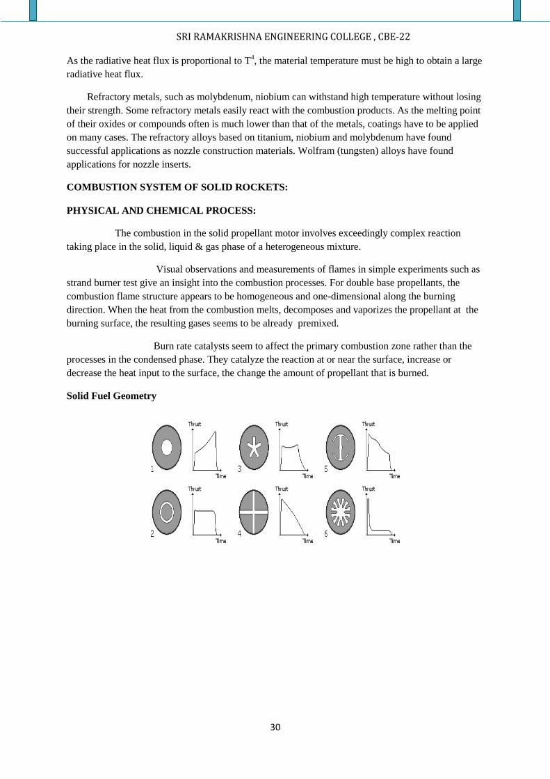
Burn rate catalysts seem to affect the primary combustion zone rather than the
processes in the condensed phase. They catalyze the reaction at or near the surface, increase or
decrease the heat input to the surface, the change the amount of propellant that is burned.
Solid Fuel Geometry
SRI RAMAKRISHNA ENGINEERING COLLEGE , CBE-22
31
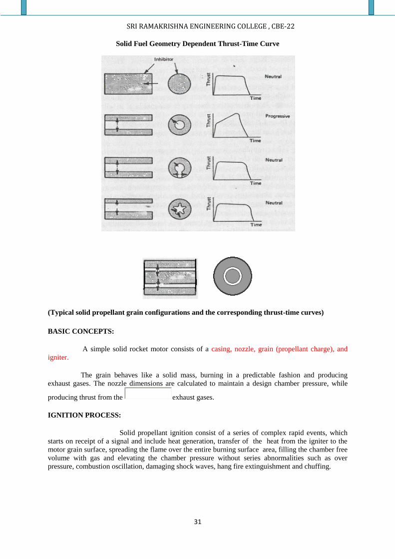
Solid Fuel Geometry Dependent Thrust-Time Curve
(Typical solid propellant grain configurations and the corresponding thrust-time curves)
BASIC CONCEPTS:
A simple solid rocket motor consists of a casing, nozzle, grain (propellant charge), and
igniter.
The grain behaves like a solid mass, burning in a predictable fashion and producing
exhaust gases. The nozzle dimensions are calculated to maintain a design chamber pressure, while
producing thrust from the exhaust gases.
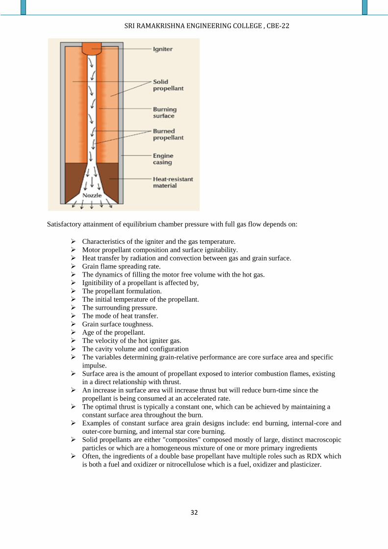
IGNITION PROCESS:
Solid propellant ignition consist of a series of complex rapid events, which
starts on receipt of a signal and include heat generation, transfer of the heat from the igniter to the
motor grain surface, spreading the flame over the entire burning surface area, filling the chamber free
volume with gas and elevating the chamber pressure without series abnormalities such as over
pressure, combustion oscillation, damaging shock waves, hang fire extinguishment and chuffing.
SRI RAMAKRISHNA ENGINEERING COLLEGE , CBE-22
32
Satisfactory attainment of equilibrium chamber pressure with full gas flow depends on:
Characteristics of the igniter and the gas temperature.
Motor propellant composition and surface ignitability.
Heat transfer by radiation and convection between gas and grain surface.
Grain flame spreading rate.
The dynamics of filling the motor free volume with the hot gas.
Ignitibility of a propellant is affected by,
The propellant formulation.
The initial temperature of the propellant.
The surrounding pressure.
The mode of heat transfer.
Grain surface toughness.
Age of the propellant.
The velocity of the hot igniter gas.
The cavity volume and configuration
The variables determining grain-relative performance are core surface area and specific
impulse.
Surface area is the amount of propellant exposed to interior combustion flames, existing
in a direct relationship with thrust.
An increase in surface area will increase thrust but will reduce burn-time since the
propellant is being consumed at an accelerated rate.
The optimal thrust is typically a constant one, which can be achieved by maintaining a
constant surface area throughout the burn.
Examples of constant surface area grain designs include: end burning, internal-core and
outer-core burning, and internal star core burning.
Solid propellants are either "composites" composed mostly of large, distinct macroscopic
particles or which are a homogeneous mixture of one or more primary ingredients
Often, the ingredients of a double base propellant have multiple roles such as RDX which
is both a fuel and oxidizer or nitrocellulose which is a fuel, oxidizer and plasticizer.
SRI RAMAKRISHNA ENGINEERING COLLEGE , CBE-22
33
Grain:
Solid fuel grains are usually molded from a thermoset elastomer (which doubles as
fuel), additional fuel, oxidizer, and catalyst. HTPB is commonly used for this purpose.
Ammonium perchlorate is the most common oxidizer used today.
The fuel is cast in different forms for different purposes. Slow, long burning
rockets have a cylinder shaped grain, burning from one end to the other. Most grains,
however, are cast with a hollow cross section, burning from the inside out (and outside in, if not case
bonded), as well as from the ends.
The thrust profile over time can be controlled by grain geometry. For example, a star
shaped hole down the center of the grain will have greater initial thrust because of the
additional surface area. As the star points are burned up, the surface
area and thrust are reduced.
Casing:
The casing may be constructed from a range of materials. Cardboard is used for model
engines. Steel is used for the space shuttle boosters. Filament wound graphite epoxy casings are used
for high performancemotors.
Nozzle:
A Convergent Divergent design accelerates the exhaust gas out of the nozzle to produce
thrust. Sophisticated solid rocket motors use steerable nozzles for rocket control.
COMBUSTION MECHANISM OF SOLID PROPELLANTS:
Some solid rocket propellants are mixed at the molecular level. A double base
propellant made from nitrocellulose and nitro-glycerin. The dominant difference is the break in
temperature slope at the solid gas interface. The solid usually requires some heat input to gasify and
this heat is the heat of pyrolysis.
Consequently, the gas phase heat transfer at the interface goes towards providing both
the latent heat and continued heat transfer into the solid.
Advantages:
Solid propellant rockets are much easier to store and handle than liquid propellant
rockets.
High propellant density makes for compact size as well.
These features plus simplicity and low cost make solid propellant rockets ideal for
military applications.
These features plus simplicity and low cost make solid propellant rockets ideal for
military applications whenever large amounts of thrust are needed and cost is an issue.
SRI RAMAKRISHNA ENGINEERING COLLEGE , CBE-22
34
Disadvantages:
Relative to liquid fuel rockets, solid fuel rockets have lower specific impulse.
The propellant mass ratios of solid propellant upper stages is usually in the .91 to .93
range which is as good or better than that of most liquid propellant upper stages but
overall performance is less than for liquid stages because of the solids' lower exhaust
velocities.
Solid rockets cannot be throttled in real time.
Solid fuel rockets are intolerant to cracks and voids.
COMBUSTION INSTABILITY
Combustion instability occurs when normal velocity (Vn) is not equal to the combustion velocity or
flame velocity(Vf).
There are 2 types of combustion instability:
1) Set of acoustic resonance, which can occur with any rocket motor.
2) Vortex shedding phenomenon, which only with particular type of propellant grains.
These two types of problems, mainly occurs only when the rocket combustion is not
controlled. It causes excessive pressure vibration forces or excessive heat transfer.
The combustion in liquid rocket is never perfectly smooth, there are some fluctuations
of pressure, temperature, and velocities are present.
ROUGH COMBUSTION:
Rough combustion is defined as the Combustion that gives greater pressure fluctuation at a
chamber wall location whichoccurs at completely random intervals is called rough combustion.
POGO OSCILLATION:
Periodic variations of thrust, caused by combustion instability or longitudinal vibrations of
structures between the tanks and the engines which modulate the propellant flow, are known as "pogo
oscillations" or "pogo", named after the Pogo stick.
Three different types of combustion instabilities occur. Some of them are,
CHUGGING:
Chugging, the first type of combustion instability occurs mostly from the elastic nature of the feed
systems and due to low frequency in the feed system which ranges from 100-400 HZ. This can cause
cyclic variation in thrust, and the effects can vary from merely annoying to actually damaging the
payload or vehicle. Chugging can be minimized by using gas-filled damping tubes on feed lines of
high density propellants.
BUZZING:
This is the intermediate type of instability and its frequency ranges from 400-1000HZ. This can be
caused due to insufficient pressure drop across the injectors. It generally is mostly annoying, rather
SRI RAMAKRISHNA ENGINEERING COLLEGE , CBE-22
35
than being damaging. However, in extreme cases combustion can end up being forced backwards
through the injectors. This can cause explosions with monopropellants.
SCREECHING (OR) SCREAMING (OR) SQUEALING:
This is the third type of instability which has higher frequency of range 1000HZ and above. It is
mostly perplexing which occurs both liquid and solid propellant rockets. This type is most destructing
and has capability of destroying the engine much less than 1 sec.
POPPING:
Popping is an undesirable random high amplitude pressure disturbance that occurs during steady state
operation of a rocket engine with hypergolic propellant. It’s one of the pressure source triggering high
frequency, instability in a rocket engine.
ELIMINATION OF POPPING:
The elimination of popping is usually achieved by re-design of the injector rather than the application
of baffles and absorbers.
ANSWER THE FOLLOWING IN SHORT
1. What is an igniter?
2. Name the types of igniters
3. What are the types of liquid igniter?
4. State any 5 characteristics of hypergolic liquids
5. State any 4 combinations of hypergolic ignition
6. Name the factors which affect the ignition delay and also give its equation with its terms
7. Classify solid rockets
8. Give the advantage and disadvantages of a bag igniter
9. Give the disadvantage of a basket igniters
10. What are the important components of a pyrotechnic igniter?
11. Give any 4 characteristics of squib
12. What are the factors to be considered while designing an igniter?
13. Distinguish between pressure feed system and pump feed system
14. What is geysering effect?
15. What is meant by outage?
16. Define combustion instability
17. Define cavitation and how cavitation will be avoided?
18. What are the problems to be avoided while designing a fuel tank outlet?
19. What is meant by liquid drop out?
20. What is an injector?
21. What are the types of injectors?
22. Define atomization of fuel
23. What is meant chugging?
24. Define the term buzzing
25. Define the term screeching
26. Define the term popping
27. What is an ignitability bomb?
28. Name the components of live igniters
29. What are the methods used for cooling of thrust chambers?
30. Define the term rough combustion
31. Draw a neat sketch of solid rocket combustion chamber
32. Name the types of valves which are used in rockets.
33. What are the modes of actuations used for operating a valve in a rocket?
SRI RAMAKRISHNA ENGINEERING COLLEGE , CBE-22
36
34. Give the applications of valves in a rocket.
DETAILED ANSWERS:
1. Classify the different types of igniters with neat sketches.
2. What is an injector? What is the main difference between an injector and a carburettor?
Classify its various types with neat sketches.
3. Distinguish between Helium pressure feed system and centrifugal pump feed system.
Pictorially represent Helium pressure feed system and explain in detail.
4. Elaborately explain the propellant pump feed system with an appropriate sketch.
5. What are the important design considerations in the section of liquid rocket combustion
chamber volume and shape? List and explain them briefly.
6. What is the need for cooling a thrust chamber? What are the different methods of cooling of
thrust chambers? Explain them briefly and draw appropriate sketches wherever necessary.
7. What is propellant slosh? Discuss its effects on flight vehicles and explain how it is
controlled?
8. What are problems generally faced by a designer while designing the liquid propellant tank
outlet design? Explain them briefly
9. Explain the phenomenon, propellant hammer in a liquid propellant rocket engine with an
appropriate sketch.
10. What is geysering effect? When and where does it occur? Explain your answer with a neat
sketch.
11. Define combustion instability and explain briefly about the various types of combustion
instability.
12. Elucidate the combustion mechanism of a solid propellant rocket.

SRI RAMAKRISHNA ENGINEERING COLLEGE , CBE-22
37
UNIT-2
AERODYNAMICS OF ROCKETS AND MISSILES
AIRFRAME COMPONENTS OF A MISSILE:
The components or parts which are experienced by the course of air are known as airframe
components .The body of the missile can be divided into three major sections .They are
Nose or Fore body
Midsection or Main body
The aft or Boat tail section
Fins
MAJOR COMPONENTS OF A MISSILE
NOSE (or) FORE BODY:
It is the first and foremost component of a missile which experiences air while travelling
through the atmosphere. Several types of nose sections were used in various types of missiles. Some
of the types are,
SRI RAMAKRISHNA ENGINEERING COLLEGE , CBE-22
38
Conical fore body
Ogival fore body
Hemispherical fore body
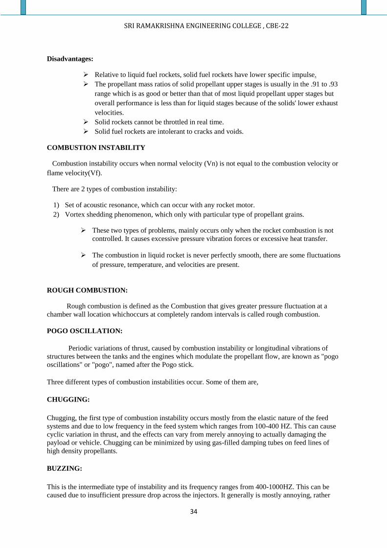
CONICAL FORE BODY:
These types of fore body are used in missiles, which are intended to fly at supersonic speeds.
The missile, while travelling in the atmosphere oblique shock is formed at the tip of the wedge
and apex of the cone. There are various aerodynamic and thermodynamic changes are noticeable
in the flow characteristics of air, in the case of conical nose.
CONICAL NOSE OF A SUPERSONIC MISSIE
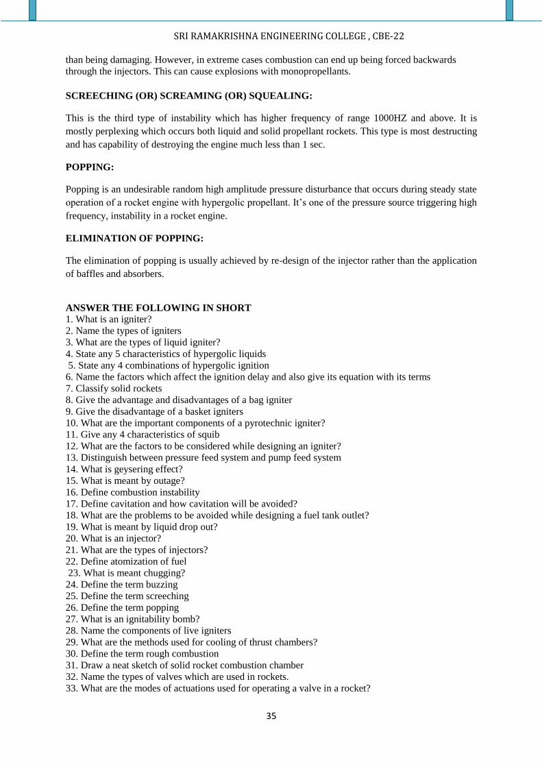
OGIVAL FORE BODY:
Ogival nose configuration is used more frequently than the conical nose. An ogive is similar
to a cone except that the plan form shaped is formed by an arc of a circle instead of a straight line as
shown in figure. The ogival shape has several advantages over the conical section.
ADVANTAGES:
1. Slightly greater volume for a given base and length(L/D ratio)
2. A blunter nose provides structural superiority.
3. Slightly lower drag.
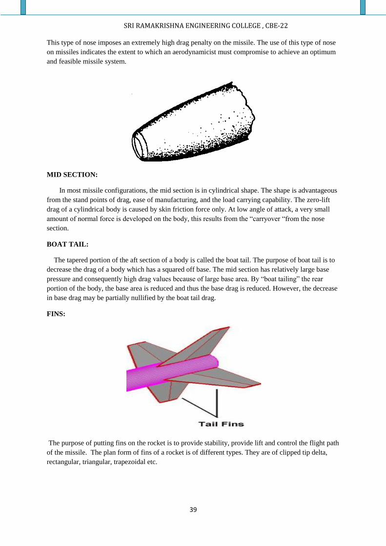
HEMISPHERICAL FORE BODY:
This type of nose is used on some of the missiles, particularly those which use IR
(infrared) seekers.
SRI RAMAKRISHNA ENGINEERING COLLEGE , CBE-22
39
This type of nose imposes an extremely high drag penalty on the missile. The use of this type of nose
on missiles indicates the extent to which an aerodynamicist must compromise to achieve an optimum
and feasible missile system.
MID SECTION:
In most missile configurations, the mid section is in cylindrical shape. The shape is advantageous
from the stand points of drag, ease of manufacturing, and the load carrying capability. The zero-lift
drag of a cylindrical body is caused by skin friction force only. At low angle of attack, a very small
amount of normal force is developed on the body, this results from the “carryover “from the nose
section.
BOAT TAIL:
The tapered portion of the aft section of a body is called the boat tail. The purpose of boat tail is to
decrease the drag of a body which has a squared off base. The mid section has relatively large base
pressure and consequently high drag values because of large base area. By “boat tailing” the rear
portion of the body, the base area is reduced and thus the base drag is reduced. However, the decrease
in base drag may be partially nullified by the boat tail drag.
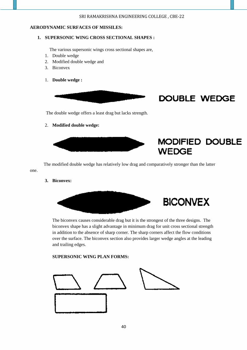
FINS:
The purpose of putting fins on the rocket is to provide stability, provide lift and control the flight path
of the missile. The plan form of fins of a rocket is of different types. They are of clipped tip delta,
rectangular, triangular, trapezoidal etc.
SRI RAMAKRISHNA ENGINEERING COLLEGE , CBE-22
40
AERODYNAMIC SURFACES OF MISSILES:
1. SUPERSONIC WING CROSS SECTIONAL SHAPES :
The various supersonic wings cross sectional shapes are,
1. Double wedge
2. Modified double wedge and
3. Biconvex
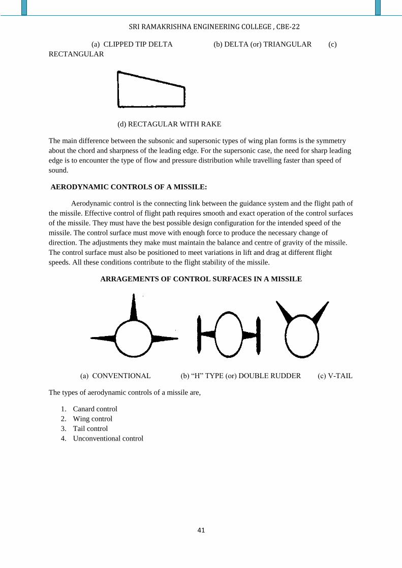
1. Double wedge :
The double wedge offers a least drag but lacks strength.
2. Modified double wedge:
The modified double wedge has relatively low drag and comparatively stronger than the latter
one.
3. Biconvex:
The biconvex causes considerable drag but it is the strongest of the three designs. The
biconvex shape has a slight advantage in minimum drag for unit cross sectional strength
in addition to the absence of sharp corner. The sharp corners affect the flow conditions
over the surface. The biconvex section also provides larger wedge angles at the leading
and trailing edges.
SUPERSONIC WING PLAN FORMS:
SRI RAMAKRISHNA ENGINEERING COLLEGE , CBE-22
41
(a) CLIPPED TIP DELTA (b) DELTA (or) TRIANGULAR (c)
RECTANGULAR
(d) RECTAGULAR WITH RAKE
The main difference between the subsonic and supersonic types of wing plan forms is the symmetry
about the chord and sharpness of the leading edge. For the supersonic case, the need for sharp leading
edge is to encounter the type of flow and pressure distribution while travelling faster than speed of
sound.
AERODYNAMIC CONTROLS OF A MISSILE:
Aerodynamic control is the connecting link between the guidance system and the flight path of
the missile. Effective control of flight path requires smooth and exact operation of the control surfaces
of the missile. They must have the best possible design configuration for the intended speed of the
missile. The control surface must move with enough force to produce the necessary change of
direction. The adjustments they make must maintain the balance and centre of gravity of the missile.
The control surface must also be positioned to meet variations in lift and drag at different flight
speeds. All these conditions contribute to the flight stability of the missile.
ARRAGEMENTS OF CONTROL SURFACES IN A MISSILE
(a) CONVENTIONAL (b) “H” TYPE (or) DOUBLE RUDDER (c) V-TAIL
The types of aerodynamic controls of a missile are,
1. Canard control
2. Wing control
3. Tail control
4. Unconventional control
SRI RAMAKRISHNA ENGINEERING COLLEGE , CBE-22
42
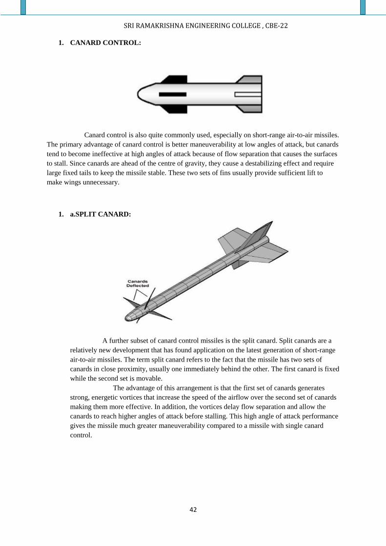
1. CANARD CONTROL:
Canard control is also quite commonly used, especially on short-range air-to-air missiles.
The primary advantage of canard control is better maneuverability at low angles of attack, but canards
tend to become ineffective at high angles of attack because of flow separation that causes the surfaces
to stall. Since canards are ahead of the centre of gravity, they cause a destabilizing effect and require
large fixed tails to keep the missile stable. These two sets of fins usually provide sufficient lift to
make wings unnecessary.
1. a.SPLIT CANARD:
A further subset of canard control missiles is the split canard. Split canards are a
relatively new development that has found application on the latest generation of short-range
air-to-air missiles. The term split canard refers to the fact that the missile has two sets of
canards in close proximity, usually one immediately behind the other. The first canard is fixed
while the second set is movable.
The advantage of this arrangement is that the first set of canards generates
strong, energetic vortices that increase the speed of the airflow over the second set of canards
making them more effective. In addition, the vortices delay flow separation and allow the
canards to reach higher angles of attack before stalling. This high angle of attack performance
gives the missile much greater maneuverability compared to a missile with single canard
control.
SRI RAMAKRISHNA ENGINEERING COLLEGE , CBE-22
43
AERODYNAMIC CHARACTERISTICS OF CANARD CONTROL:
1. The canard control missile has the advantage of small control surfaces for longitudinal control
and it places the portion of the control equipment well forward in the body out of the way of
the main propulsion and guidance unit.
2. This type tends to give low drag as much as the main lifting surfaces fixed and it can be made
of large sweep back type where in the lift to drag ratio can be optimized.
3. The canard control surfaces are deflected in the positive manner that is the leading edge
upward to provide a positive angle of attack of the missile and this is in turn places the control
surfaces at quite large angle of attack relative to the free stream especially when the missiles
pitched to large angles.
4. This change tends to increase loads and hinge moments on the control surfaces. High control
surface rates and hence high power will be required, to increase the angle of attack to acquire
the required maneuver.
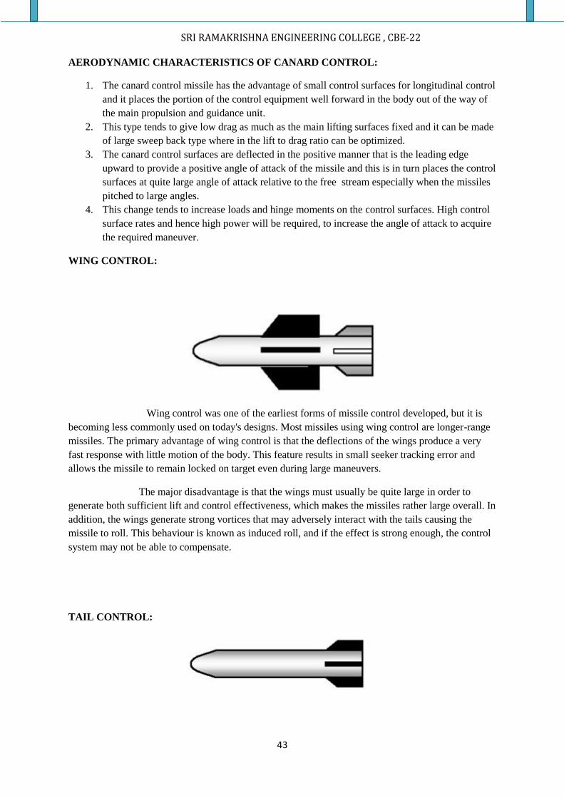
WING CONTROL:
Wing control was one of the earliest forms of missile control developed, but it is
becoming less commonly used on today's designs. Most missiles using wing control are longer-range
missiles. The primary advantage of wing control is that the deflections of the wings produce a very
fast response with little motion of the body. This feature results in small seeker tracking error and
allows the missile to remain locked on target even during large maneuvers.
The major disadvantage is that the wings must usually be quite large in order to
generate both sufficient lift and control effectiveness, which makes the missiles rather large overall. In
addition, the wings generate strong vortices that may adversely interact with the tails causing the
missile to roll. This behaviour is known as induced roll, and if the effect is strong enough, the control
system may not be able to compensate.
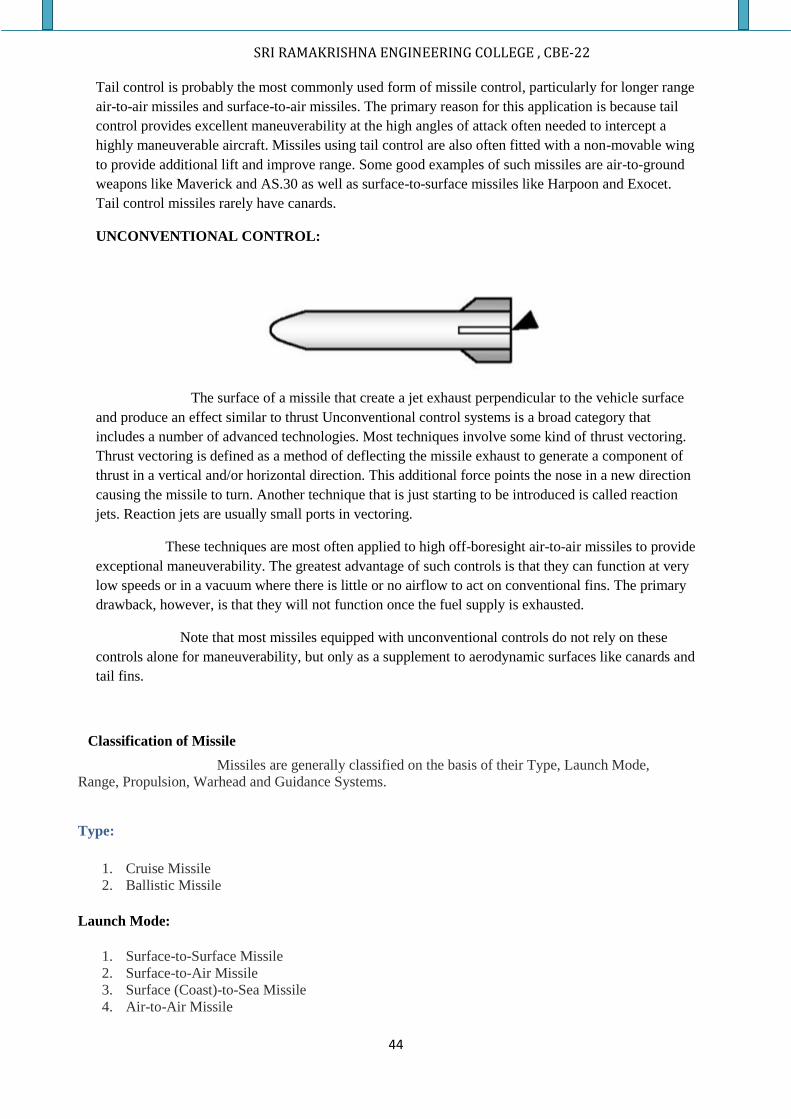
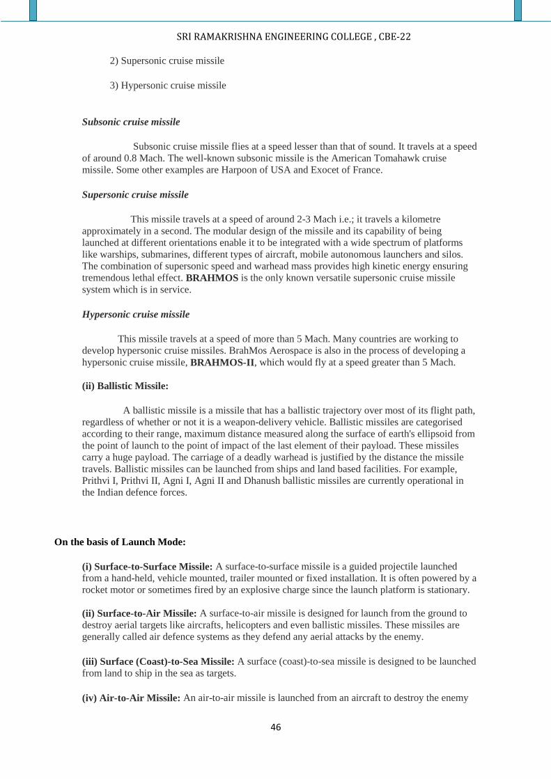
TAIL CONTROL:
SRI RAMAKRISHNA ENGINEERING COLLEGE , CBE-22
44
Tail control is probably the most commonly used form of missile control, particularly for longer range
air-to-air missiles and surface-to-air missiles. The primary reason for this application is because tail
control provides excellent maneuverability at the high angles of attack often needed to intercept a
highly maneuverable aircraft. Missiles using tail control are also often fitted with a non-movable wing
to provide additional lift and improve range. Some good examples of such missiles are air-to-ground
weapons like Maverick and AS.30 as well as surface-to-surface missiles like Harpoon and Exocet.
Tail control missiles rarely have canards.
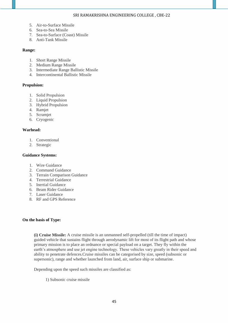
UNCONVENTIONAL CONTROL:
The surface of a missile that create a jet exhaust perpendicular to the vehicle surface
and produce an effect similar to thrust Unconventional control systems is a broad category that
includes a number of advanced technologies. Most techniques involve some kind of thrust vectoring.
Thrust vectoring is defined as a method of deflecting the missile exhaust to generate a component of
thrust in a vertical and/or horizontal direction. This additional force points the nose in a new direction
causing the missile to turn. Another technique that is just starting to be introduced is called reaction
jets. Reaction jets are usually small ports in vectoring.
These techniques are most often applied to high off-boresight air-to-air missiles to provide
exceptional maneuverability. The greatest advantage of such controls is that they can function at very
low speeds or in a vacuum where there is little or no airflow to act on conventional fins. The primary
drawback, however, is that they will not function once the fuel supply is exhausted.
Note that most missiles equipped with unconventional controls do not rely on these
controls alone for maneuverability, but only as a supplement to aerodynamic surfaces like canards and
tail fins.
Classification of Missile
Missiles are generally classified on the basis of their Type, Launch Mode,
Range, Propulsion, Warhead and Guidance Systems.
Type:
1. Cruise Missile
2. Ballistic Missile
Launch Mode:
1. Surface-to-Surface Missile
2. Surface-to-Air Missile
3. Surface (Coast)-to-Sea Missile
4. Air-to-Air Missile
SRI RAMAKRISHNA ENGINEERING COLLEGE , CBE-22
45
5. Air-to-Surface Missile
6. Sea-to-Sea Missile
7. Sea-to-Surface (Coast) Missile
8. Anti-Tank Missile
Range:
1. Short Range Missile
2. Medium Range Missile
3. Intermediate Range Ballistic Missile
4. Intercontinental Ballistic Missile
Propulsion:
1. Solid Propulsion
2. Liquid Propulsion
3. Hybrid Propulsion
4. Ramjet
5. Scramjet
6. Cryogenic
Warhead:
1. Conventional
2. Strategic
Guidance Systems:
1. Wire Guidance
2. Command Guidance
3. Terrain Comparison Guidance
4. Terrestrial Guidance
5. Inertial Guidance
6. Beam Rider Guidance
7. Laser Guidance
8. RF and GPS Reference
On the basis of Type:
(i) Cruise Missile: A cruise missile is an unmanned self-propelled (till the time of impact)
guided vehicle that sustains flight through aerodynamic lift for most of its flight path and whose
primary mission is to place an ordnance or special payload on a target. They fly within the
earth’s atmosphere and use jet engine technology. These vehicles vary greatly in their speed and
ability to penetrate defences.Cruise missiles can be categorised by size, speed (subsonic or
supersonic), range and whether launched from land, air, surface ship or submarine.
Depending upon the speed such missiles are classified as:
1) Subsonic cruise missile
SRI RAMAKRISHNA ENGINEERING COLLEGE , CBE-22
46
2) Supersonic cruise missile
3) Hypersonic cruise missile
Subsonic cruise missile
Subsonic cruise missile flies at a speed lesser than that of sound. It travels at a speed
of around 0.8 Mach. The well-known subsonic missile is the American Tomahawk cruise
missile. Some other examples are Harpoon of USA and Exocet of France.
Supersonic cruise missile
This missile travels at a speed of around 2-3 Mach i.e.; it travels a kilometre
approximately in a second. The modular design of the missile and its capability of being
launched at different orientations enable it to be integrated with a wide spectrum of platforms
like warships, submarines, different types of aircraft, mobile autonomous launchers and silos.
The combination of supersonic speed and warhead mass provides high kinetic energy ensuring
tremendous lethal effect. BRAHMOS is the only known versatile supersonic cruise missile
system which is in service.
Hypersonic cruise missile
This missile travels at a speed of more than 5 Mach. Many countries are working to
develop hypersonic cruise missiles. BrahMos Aerospace is also in the process of developing a
hypersonic cruise missile, BRAHMOS-II, which would fly at a speed greater than 5 Mach.
(ii) Ballistic Missile:
A ballistic missile is a missile that has a ballistic trajectory over most of its flight path,
regardless of whether or not it is a weapon-delivery vehicle. Ballistic missiles are categorised
according to their range, maximum distance measured along the surface of earth's ellipsoid from
the point of launch to the point of impact of the last element of their payload. These missiles
carry a huge payload. The carriage of a deadly warhead is justified by the distance the missile
travels. Ballistic missiles can be launched from ships and land based facilities. For example,
Prithvi I, Prithvi II, Agni I, Agni II and Dhanush ballistic missiles are currently operational in
the Indian defence forces.
On the basis of Launch Mode:
(i) Surface-to-Surface Missile: A surface-to-surface missile is a guided projectile launched
from a hand-held, vehicle mounted, trailer mounted or fixed installation. It is often powered by a
rocket motor or sometimes fired by an explosive charge since the launch platform is stationary.
(ii) Surface-to-Air Missile: A surface-to-air missile is designed for launch from the ground to
destroy aerial targets like aircrafts, helicopters and even ballistic missiles. These missiles are
generally called air defence systems as they defend any aerial attacks by the enemy.
(iii) Surface (Coast)-to-Sea Missile: A surface (coast)-to-sea missile is designed to be launched
from land to ship in the sea as targets.
(iv) Air-to-Air Missile: An air-to-air missile is launched from an aircraft to destroy the enemy
SRI RAMAKRISHNA ENGINEERING COLLEGE , CBE-22
47
aircraft. The missile flies at a speed of 4 Mach.
(v) Air-to-Surface Missile: An air-to-surface missile is designed for launch from military
aircraft and strikes ground targets on land, at sea or both. The missiles are basically guided via
laser guidance, infrared guidance and optical guidance or via GPS signals. The type of guidance
depends on the type of target.
(vi) Sea-to-Sea Missile: A sea-to-sea missile is designed for launch from one ship to another
ship.
(vii) Sea-to-Surface (Coast) Missile: A sea-to-surface missile is designed for launch from ship
to land based targets.
(viii) Anti-Tank Missile: An anti-tank missile is a guided missile primarily designed to hit and
destroy heavily-armoured tanks and other armoured fighting vehicles. Anti-tank missiles could
be launched from aircraft, helicopters, tanks and also from shoulder mounted launcher.
On the basis of Range:
This type of classification is based on maximum range achieved by the missiles. The basic
classification is as follows:
(i) Short Range Missile
(ii) Medium Range Missile
(iii) Intermediate Range Ballistic Missile
(iv) Intercontinental Ballistic Missile
On the basis of Propulsion:
(i) Solid Propulsion: Solid fuel is used in solid propulsion. Generally, the fuel is aluminium
powder. Solid propulsion has the advantage of being easily stored and can be handled in fuelled
condition. It can reach very high speeds quickly. Its simplicity also makes it a good choice
whenever large amount of thrust is needed.
(ii) Liquid Propulsion: The liquid propulsion technology uses liquid as fuel. The fuels are
hydrocarbons. The storage of missile with liquid fuel is difficult and complex. In addition,
preparation of missile takes considerable time. In liquid propulsion, propulsion can be
controlled easily by restricting the fuel flow by using valves and it can also be controlled even
under emergency conditions. Basically, liquid fuel gives high specific impulse as compared to
solid fuel.
(ii) Hybrid Propulsion: There are two stages in hybrid propulsion - solid propulsion and liquid
propulsion. This kind of propulsion compensates the disadvantages of both propulsion systems
and has the combined advantages of the two propulsion systems.
(iii) Ramjet: A ramjet engine does not have any turbines unlike turbojet engines. It achieves
compression of intake air just by the forward speed of the air vehicle. The fuel is injected and
ignited. The expansion of hot gases after fuel injection and combustion accelerates the exhaust
air to a velocity higher than that at the inlet and creates positive push. However, the air entering
the engine should be at supersonic speeds. So, the aerial vehicle must be moving in supersonic
speeds. Ramjet engines cannot propel an aerial vehicle from zero to supersonic speeds.
SRI RAMAKRISHNA ENGINEERING COLLEGE , CBE-22
48
(iv) Scramjet: Scramjet is an acronym for Supersonic Combustion Ramjet. The difference
between scramjet and ramjet is that the combustion takes place at supersonic air velocities
through the engine. It is mechanically simple, but vastly more complex aerodynamically than a
jet engine. Hydrogen is normally the fuel used.
(v) Cryogenic: Cryogenic propellants are liquefied gases stored at very low temperatures, most
frequently liquid hydrogen as the fuel and liquid oxygen as the oxidizer. Cryogenic propellants
require special insulated containers and vents which allow gas to escape from the evaporating
liquids. The liquid fuel and oxidizer are pumped from the storage tanks to an expansion chamber
and injected into the combustion chamber where they are mixed and ignited by a flame or spark.
The fuel expands as it burns and the hot exhaust gases are directed out of the nozzle to provide
thrust.
On the basis of Warhead:
(i) Conventional Warhead: A conventional warhead contains high energy explosives. It is
filled with a chemi al explosive and relies on the detonation of the explosive and the resulting
metal casing fragmentation as kill mechanisms.
(ii) Strategic Warhead: In a strategic warhead, radio active materials are present and when
triggered they exhibit huge radio activity that can wipe out even cities. They are generally
designed for mass annihilation.
On the basis of Guidance Systems:
(i) Wire Guidance: This system is broadly similar to radio command, but is less susceptible to
electronic counter measures. The command signals are passed along a wire (or wires) dispensed
from the missile after launch.
(ii) Command Guidance: Command guidance involves tracking the projectile from the launch
site or platform and transmitting commands by radio, radar, or laser impulses or along thin wires
or optical fibres. Tracking might be accomplished by radar or optical instruments from the
launch site or by radar or television imagery relayed from the missile.
(iii) Terrain Comparison Guidance: Terrain Comparison (TERCOM) is used invariably by
cruise missiles. The system uses sensitive altimeters to measure the profile of the ground
directly below and checks the result against stored information.
(iv) Terrestrial Guidance: This system constantly measures star angles and compares them
with the pre-programmed angles expected on the missile’s intended trajectory. The guidance
system directs the control system whenever an alteration to trajectory is required.
(v) Inertial Guidance: This system is totally contained within the missile and is programmed
prior to launch. Three accelerometers, mounted on a platform space-stabilised by gyros, measure
accelerations along three mutually perpendicular axes; these accelerations are then integrated
twice, the first integration giving velocity and the second giving position. The system then
directs the control system to preserve the pre-programmed trajectory. These systems are used in
the surface-to-surface missiles and in cruise missiles.
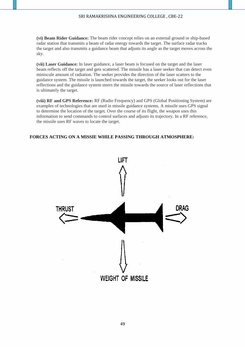
SRI RAMAKRISHNA ENGINEERING COLLEGE , CBE-22
49
(vi) Beam Rider Guidance: The beam rider concept relies on an external ground or ship-based
radar station that transmits a beam of radar energy towards the target. The surface radar tracks
the target and also transmits a guidance beam that adjusts its angle as the target moves across the
sky.
(vii) Laser Guidance: In laser guidance, a laser beam is focused on the target and the laser
beam reflects off the target and gets scattered. The missile has a laser seeker that can detect even
miniscule amount of radiation. The seeker provides the direction of the laser scatters to the
guidance system. The missile is launched towards the target, the seeker looks out for the laser
reflections and the guidance system steers the missile towards the source of laser reflections that
is ultimately the target.
(viii) RF and GPS Reference: RF (Radio Frequency) and GPS (Global Positioning System) are
examples of technologies that are used in missile guidance systems. A missile uses GPS signal
to determine the location of the target. Over the course of its flight, the weapon uses this
information to send commands to control surfaces and adjusts its trajectory. In a RF reference,
the missile uses RF waves to locate the target.
FORCES ACTING ON A MISSIE WHILE PASSING THROUGH ATMOSPHERE:
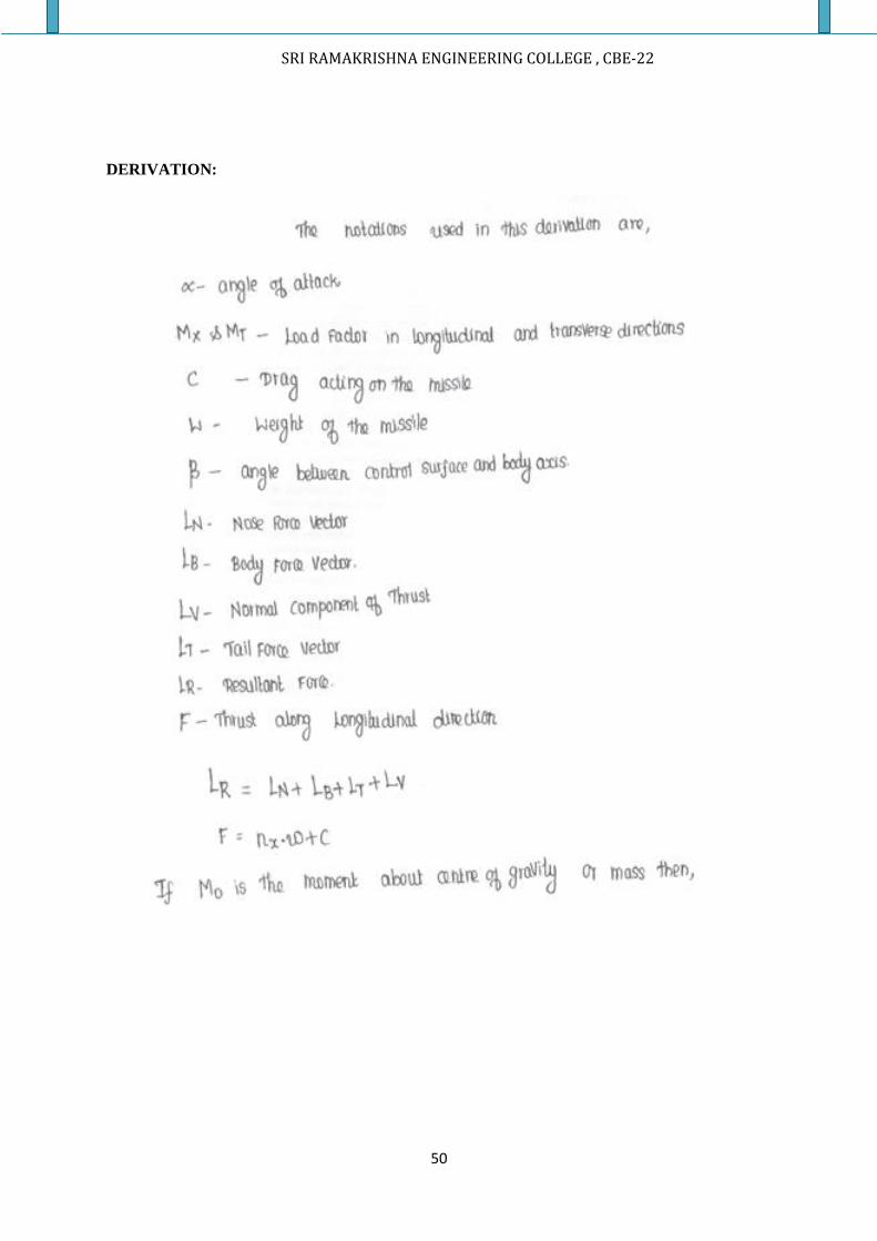
SRI RAMAKRISHNA ENGINEERING COLLEGE , CBE-22
50
DERIVATION:

SRI RAMAKRISHNA ENGINEERING COLLEGE , CBE-22
51
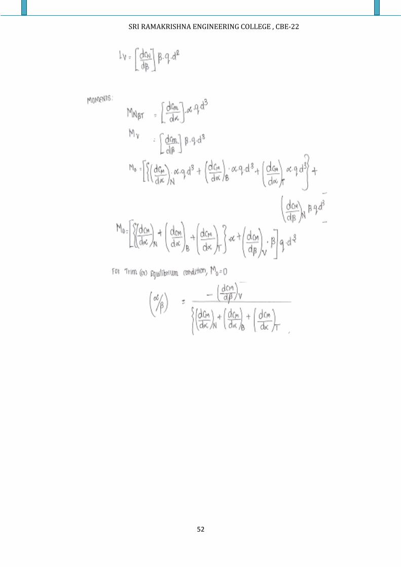
SRI RAMAKRISHNA ENGINEERING COLLEGE , CBE-22
52
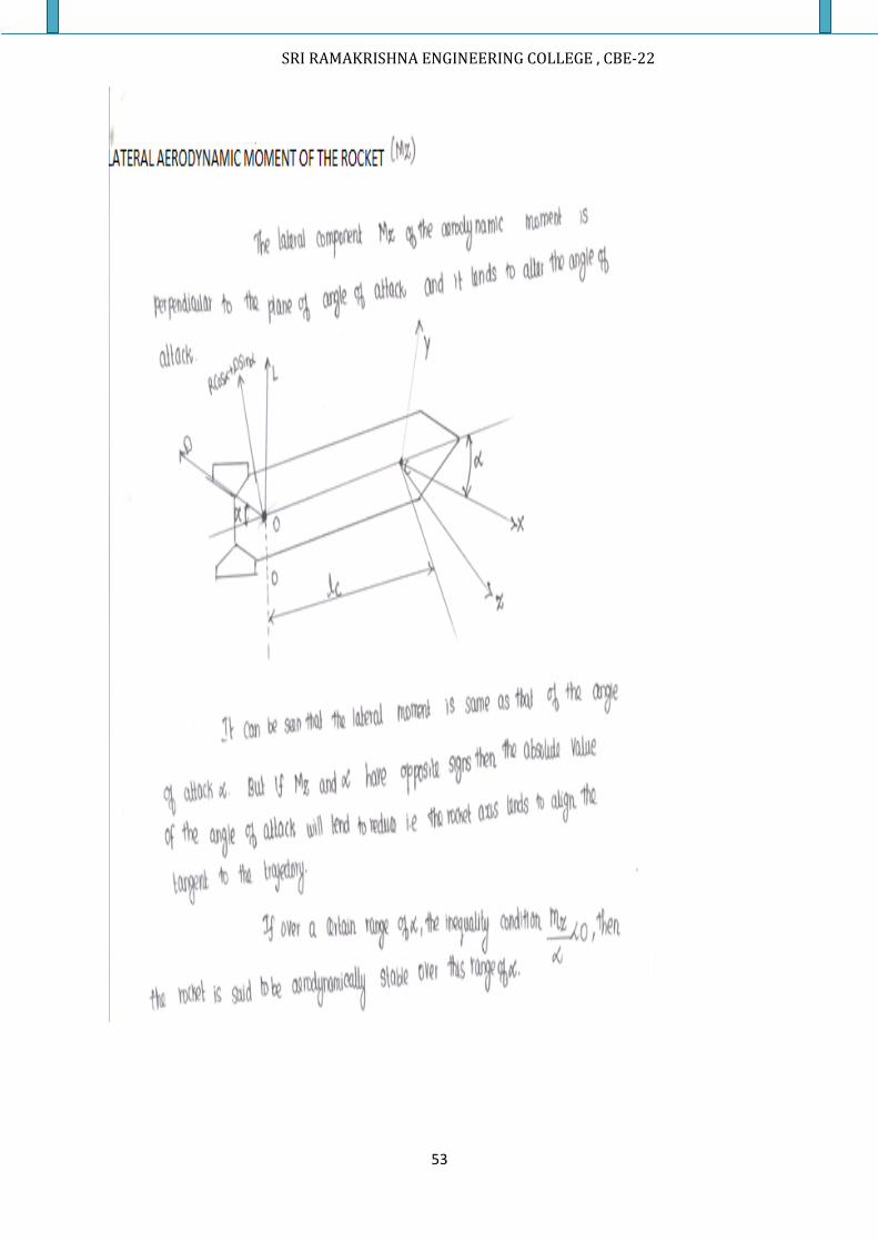
SRI RAMAKRISHNA ENGINEERING COLLEGE , CBE-22
53
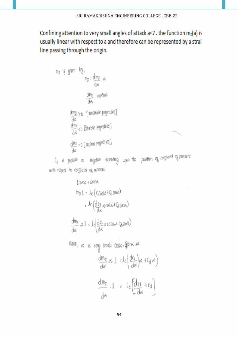
SRI RAMAKRISHNA ENGINEERING COLLEGE , CBE-22
54
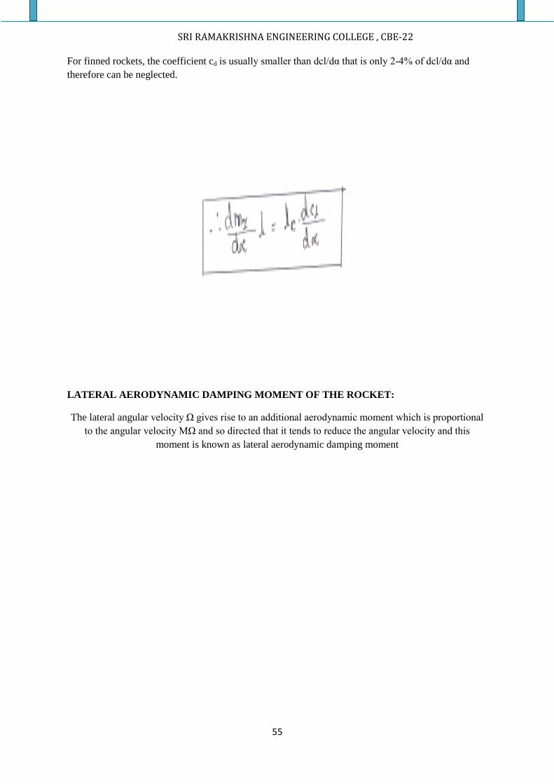
SRI RAMAKRISHNA ENGINEERING COLLEGE , CBE-22
55
For finned rockets, the coefficient cd is usually smaller than dcl/dα that is only 2-4% of dcl/dα and
therefore can be neglected.
LATERAL AERODYNAMIC DAMPING MOMENT OF THE ROCKET:
The lateral angular velocity Ω gives rise to an additional aerodynamic moment which is proportional
to the angular velocity MΩ and so directed that it tends to reduce the angular velocity and this
moment is known as lateral aerodynamic damping moment
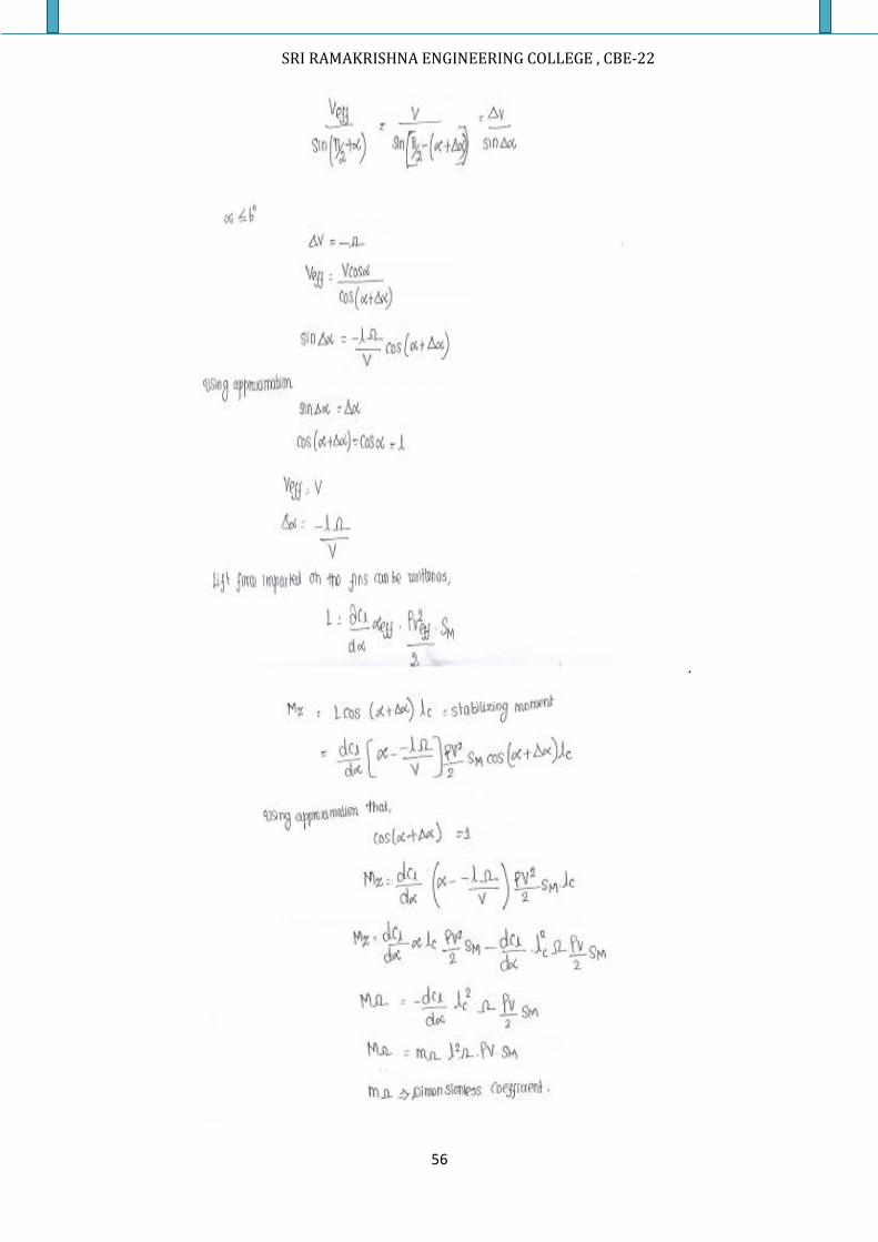
SRI RAMAKRISHNA ENGINEERING COLLEGE , CBE-22
56
.
SRI RAMAKRISHNA ENGINEERING COLLEGE , CBE-22
57
LONGITUDINAL AERODYNAMIC MOMENT:
In case of symmetric finned rockets the component Mx of the aerodynamic moment
along a longitudinal axis is zero. However it is not for the rockets with slanted fins. In such a rocket
each fin is mounted to make certain angle with longitudinal axis in such a way that on rotation of
missile through 360/n degrees (n-number of fins). Each fin assumes the position occupied by the
adjacent fin prior rotation when fins are slant mounted, a moment arises during the flight, which tends
to rotate the rocket about its axis of symmetry.
For simplicity study the motion of such rocket at an angle of attack, α=0.
Since each fin encounters the airflow at an angle, the fins are acted upon by a lift force L,
perpendicular to the rocket axis. The centre of pressure of this force i.e the point of intersection of its
line of action with the plane of the fin is at a distance of rc.
If there are n number of fins the total longitudinal moment is n.L1.rc . since the lift force is
proportional to the air density and the square of the velocity and further to the fin angle ε.
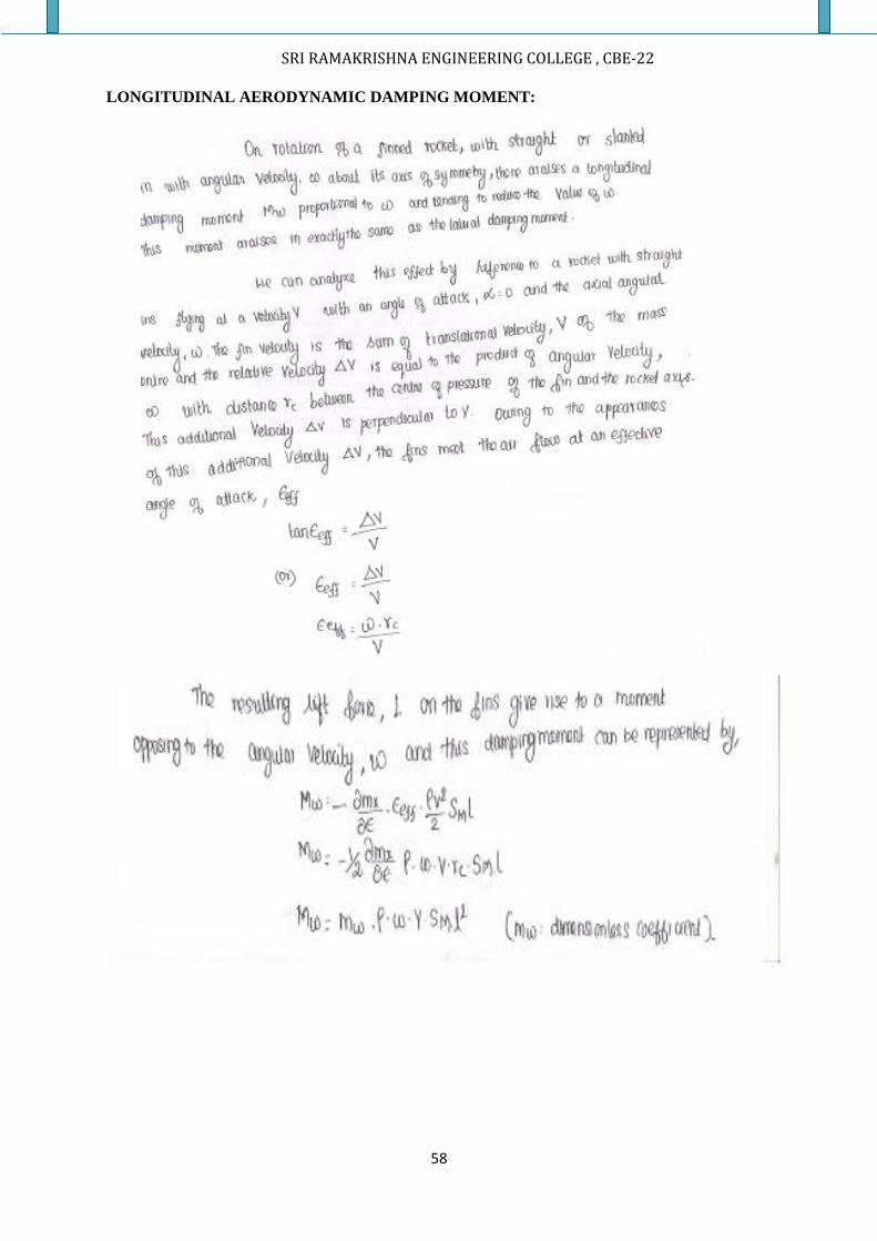
SRI RAMAKRISHNA ENGINEERING COLLEGE , CBE-22
58
LONGITUDINAL AERODYNAMIC DAMPING MOMENT:
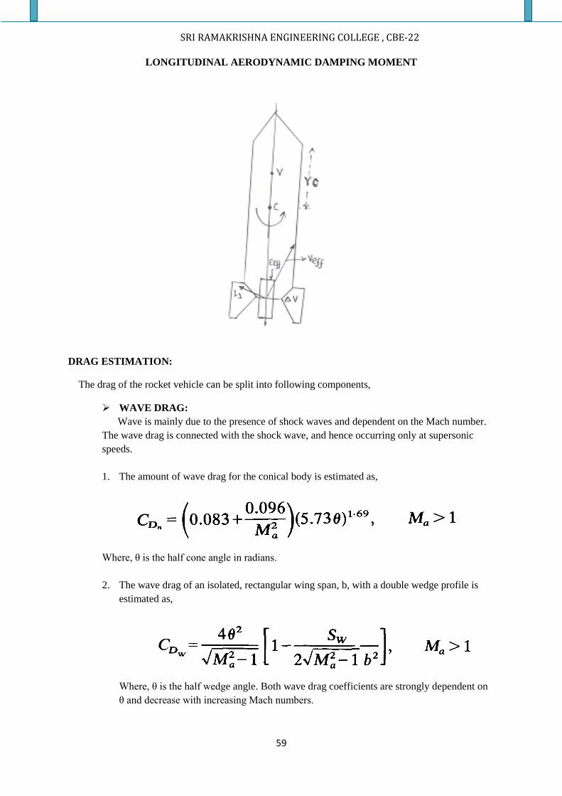
SRI RAMAKRISHNA ENGINEERING COLLEGE , CBE-22
59
LONGITUDINAL AERODYNAMIC DAMPING MOMENT
DRAG ESTIMATION:
The drag of the rocket vehicle can be split into following components,
WAVE DRAG:
Wave is mainly due to the presence of shock waves and dependent on the Mach number.
The wave drag is connected with the shock wave, and hence occurring only at supersonic
speeds.
1. The amount of wave drag for the conical body is estimated as,
Where, θ is the half cone angle in radians.
2. The wave drag of an isolated, rectangular wing span, b, with a double wedge profile is
estimated as,
Where, θ is the half wedge angle. Both wave drag coefficients are strongly dependent on
θ and decrease with increasing Mach numbers.
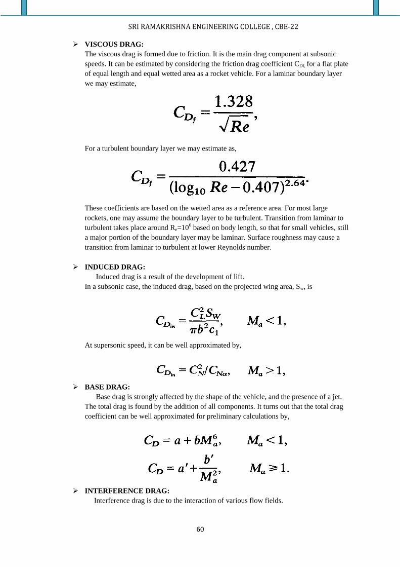
SRI RAMAKRISHNA ENGINEERING COLLEGE , CBE-22
60
VISCOUS DRAG:
The viscous drag is formed due to friction. It is the main drag component at subsonic
speeds. It can be estimated by considering the friction drag coefficient CDf, for a flat plate
of equal length and equal wetted area as a rocket vehicle. For a laminar boundary layer
we may estimate,
For a turbulent boundary layer we may estimate as,
These coefficients are based on the wetted area as a reference area. For most large
rockets, one may assume the boundary layer to be turbulent. Transition from laminar to
turbulent takes place around Re=106 based on body length, so that for small vehicles, still
a major portion of the boundary layer may be laminar. Surface roughness may cause a
transition from laminar to turbulent at lower Reynolds number.
INDUCED DRAG:
Induced drag is a result of the development of lift.
In a subsonic case, the induced drag, based on the projected wing area, Sw, is
At supersonic speed, it can be well approximated by,
BASE DRAG:
Base drag is strongly affected by the shape of the vehicle, and the presence of a jet.
The total drag is found by the addition of all components. It turns out that the total drag
coefficient can be well approximated for preliminary calculations by,
INTERFERENCE DRAG:
Interference drag is due to the interaction of various flow fields.
SRI RAMAKRISHNA ENGINEERING COLLEGE , CBE-22
61
ROUGHNESS DRAG:
It is mainly due to the surface roughness such as rivets and welds.
ROCKET DISPERSION:
DISPERSION-DEFINITION
Dispersion is defined as the measure of deviation of the rocket’s trajectory from the
standard nominal trajectory.
For a rocket, dispersion arises from three different sources. They are,
1. Events that occur at launching,
2. Events during burning after launching, and
3. Events after burning.
For rockets, most of the dispersion arises during the burning period after launching.
FACTORS CAUSING DISPERSION:
The factors that induce dispersion of rocket’s trajectory are,
The propellant mass and composition Inaccuracy
The rocket total mass, axial and lateral Moments of inertia and resultant centre of
gravity Inaccuracies
Launcher deflection
The thrust force of the rocket engine: because of the tolerance in rocket engine design,
propellant properties, and manufacturing
Thrust and fin misalignments: It is an important source of dispersion in case of unguided
rockets.
Atmospheric disturbances such as wind profile, tail wind, cross wind, and gusts, variation
in atmospheric density.
METHODS TO ESTIMATE DISPRSION:
There are some methods to estimate the dispersion of trajectory for a rocket. They are,
Root Mean Square Method
Monte Carlo method
Method of covariance matrix
1. The Root Mean Square Method:
The Root Mean Square Method simulates the rocket trajectory perturbing one
parameter at time and the results are compared with the nominal results. The sum of squares
deviations for all parameters is square of total deviation.
2. Monte Carlo method:
Monte Carlo method of dispersion removes smaller dispersion parameters.
Each input parameter is selected randomly in the defined ranges and used in the simulation of
trajectory.
SRI RAMAKRISHNA ENGINEERING COLLEGE , CBE-22
62
3. The Method of covariance matrix:
In probability theory and statistics, covariance is a measure of how much two
variables change together. A covariance matrix is a matrix whose element in the i, j position is the
covariance between the i th and j th elements of a random vector (that is, of a vector of random
variables). Each element of the vector is a scalar random variable, either with a finite number of
observed empirical values or with a finite or infinite number of potential values specified by a
theoretical joint probability distribution of all the random variables.
TYPES OF ROCKET DISPERSION:
There are two types of rocket dispersion, such as
I. In plane dispersion (or) Range dispersion
II. Lateral dispersion (or) Out of plane dispersion
IN-PLANE DISPERSION (or) RANGE DISPERSION:
In the absence of perturbing forces giving rise to rocket dispersion, the trajectory of the rocket
would lie in the launch plane. But practically such factors are generally active and try to produce that
cause. The dispersion of the rocket, which may be of any type sometimes the rocket, can suffer both
types.
LATERAL DISPERSION (or) OUT OF PLANE DISPERSION:
If the perturbing forces are active, the axis of the rocket will deviate from the target to the
trajectory of the mass centre by an angle known as angle of attack. Since the thrust is directed along
the axis of the rocket, the deviation gives rise to a thrust component normal to the trajectory. The
trajectory thus departs from the intended path and put the rocket away from the target.
MINIMIZATION OF ROCKET DISPERSION:
For trajectory vehicles, dispersion can be minimized by means of a special guidance system. The
guided system is thought to be known as the brain of a rocket or a missile.
The distinct tasks of a guidance system are as follows:
1. It maintains the missile in proper attitude. Using instruments like gyros, the control system
correct the problems experienced through rotation and translation motion of a rocket.
2. The control guidance system also helps in tracking the positions, computing the tracking
information, correcting the signals and then steering the rocket in a correct orbit and thus
helps in minimizing the dispersion.
Short answers:
1. What are the airframe components of a missile?
2. Name the different types of nose cones in a missile
3. What are the advantages of ogival fore body?
SRI RAMAKRISHNA ENGINEERING COLLEGE , CBE-22
63
4. What are the aerodynamic controls present in a missile?
5. What do you mean by canard control of guided missiles?
6. What is the important of boat tail in missiles?
7. Sketch the different shapes of supersonic wing cross section
8. Sketch the various supersonic wing plan forms
9. How do you classify the missiles based on navigation and mission?
10. Mention the aerodynamic characteristics of air to surface missile
11. What is meant by lateral aerodynamic damping moment?
12. Distinguish between body up wash and body downwash in missile aerodynamics
13. What are the forces which act on a trajectory vehicle while passing through the atmosphere?
14. What are the different types of drag which acts on a missile in atmosphere?
15. W hat is meant rocket by rocket dispersion?
16. What are the types of rocket dispersion?
17. What are the factors which causes rocket dispersion?
18. How do you minimize rocket dispersion?
19. What are the methods used to estimate rocket dispersion?
BRIEF ANSWERS:
1. Explain the various airframe components and various aerodynamic controls of a missile.
Draw sketches wherever necessary.
2. Explain the forces acting on a missile while passing through the atmosphere. Elucidate
your answer with a neat sketch.
3. What are the different types of drag which acts on a missile in atmosphere? Clearly
explain what wave drag is. What is its relative importance in the total drag estimation of a
supersonic missile? How is wave drag coefficient estimated for double wedge, modified
double wedge and biconvex profiles of supersonic airfoils?
4. With the help of a neat sketch clearly explain how fins impart stability to a rocket in
flight which is in atmosphere.
5. What are the various wings cross sectional shapes that are generally used for supersonic
missiles? Sketch such shapes and mention their advantages and limitations.
6. With a neat sketch clearly explain the lateral aerodynamic moment of a rocket and briefly
elucidate the variation of lateral aerodynamic moment coefficient variation with angle of
attack. How does thus variation affects the stability of the rocket flight?
7. With a neat sketch clearly explain the longitudinal aerodynamic moment of a rocket.
8. List any four basic aerodynamic design considerations for the development of air to air
missiles. What factors limits the range of such missiles?
9. Classify the various types of missiles.
10. What is rocket dispersion? How it is classified? What are the important factors that cause
dispersion? How it can be minimized?
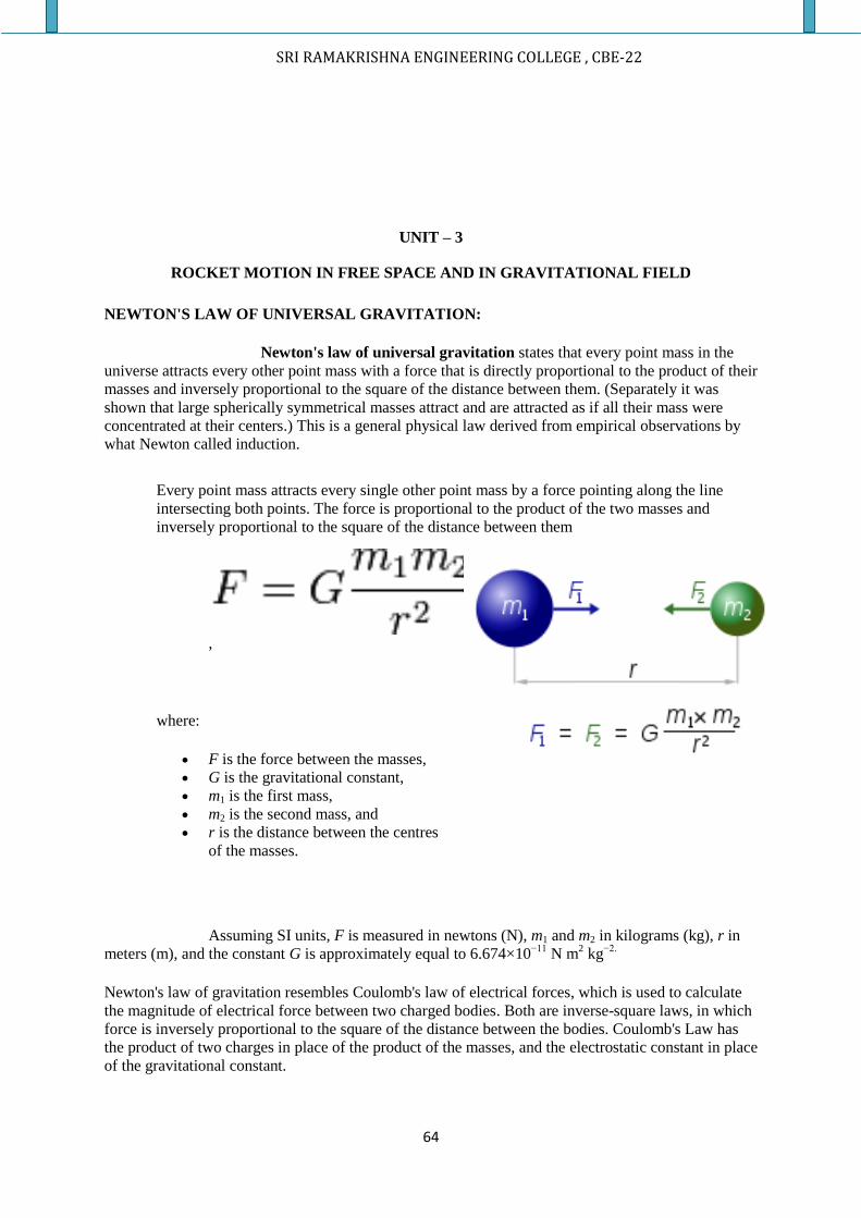
SRI RAMAKRISHNA ENGINEERING COLLEGE , CBE-22
64
UNIT – 3
ROCKET MOTION IN FREE SPACE AND IN GRAVITATIONAL FIELD
NEWTON'S LAW OF UNIVERSAL GRAVITATION:
Newton's law of universal gravitation states that every point mass in the
universe attracts every other point mass with a force that is directly proportional to the product of their
masses and inversely proportional to the square of the distance between them. (Separately it was
shown that large spherically symmetrical masses attract and are attracted as if all their mass were
concentrated at their centers.) This is a general physical law derived from empirical observations by
what Newton called induction.
Every point mass attracts every single other point mass by a force pointing along the line
intersecting both points. The force is proportional to the product of the two masses and
inversely proportional to the square of the distance between them
,
where:
F is the force between the masses,
G is the gravitational constant,
m1 is the first mass,
m2 is the second mass, and
r is the distance between the centres
of the masses.
Assuming SI units, F is measured in newtons (N), m1 and m2 in kilograms (kg), r in
meters (m), and the constant G is approximately equal to 6.674×10⁻¹¹
N m2 kg
−2.
Newton's law of gravitation resembles Coulomb's law of electrical forces, which is used to calculate
the magnitude of electrical force between two charged bodies. Both are inverse-square laws, in which
force is inversely proportional to the square of the distance between the bodies. Coulomb's Law has
the product of two charges in place of the product of the masses, and the electrostatic constant in place
of the gravitational constant.
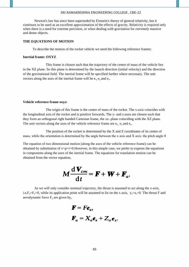
SRI RAMAKRISHNA ENGINEERING COLLEGE , CBE-22
65
Newton's law has since been superseded by Einstein's theory of general relativity, but it
continues to be used as an excellent approximation of the effects of gravity. Relativity is required only
when there is a need for extreme precision, or when dealing with gravitation for extremely massive
and dense objects.
THE EQUATIONS OF MOTION
To describe the motion of the rocket vehicle we need the following reference frames:
Inertial frame: OXYZ
This frame is chosen such that the trajectory of the centre of mass of the vehicle lies
in the XZ plane. So this plane is determined by the launch direction (initial velocity) and the direction
of the gravitational field. The inertial frame will be specified further where necessary. The unit
vectors along the axes of the inertial frame will be ex, ey and ez.
Vehicle reference frame oxyz:
The origin of this frame is the centre of mass of the rocket. The x-axis coincides with
the longitudinal axis of the rocket and is positive forwards. The y- and z-axes are chosen such that
they form an orthogonal right handed Cartesian frame, the xz- plane coinciding with the XZ plane.
The unit vectors along the axes of the vehicle reference frame are ex , ey and ez.
The position of the rocket is determined by the X and Z coordinates of its centre of
mass, while the orientation is determined by the angle between the x axis and X axis: the pitch angle θ
The equation of two dimensional motion (along the axes of the vehicle reference frame) can be
obtained by substitution of v=p=r=0.However, in this simple case, we prefer to express the equations
in components along the axes of the inertial frame. The equations for translation motion can be
obtained from the vector equation,
As we will only consider nominal trajectory, the thrust is assumed to act along the x-axis,
i.e,Fx=Fy=0, while its application point will be assumed to lie on the x axis, ye=ze=0. The thrust F and
aerodynamic force Fa are given by,
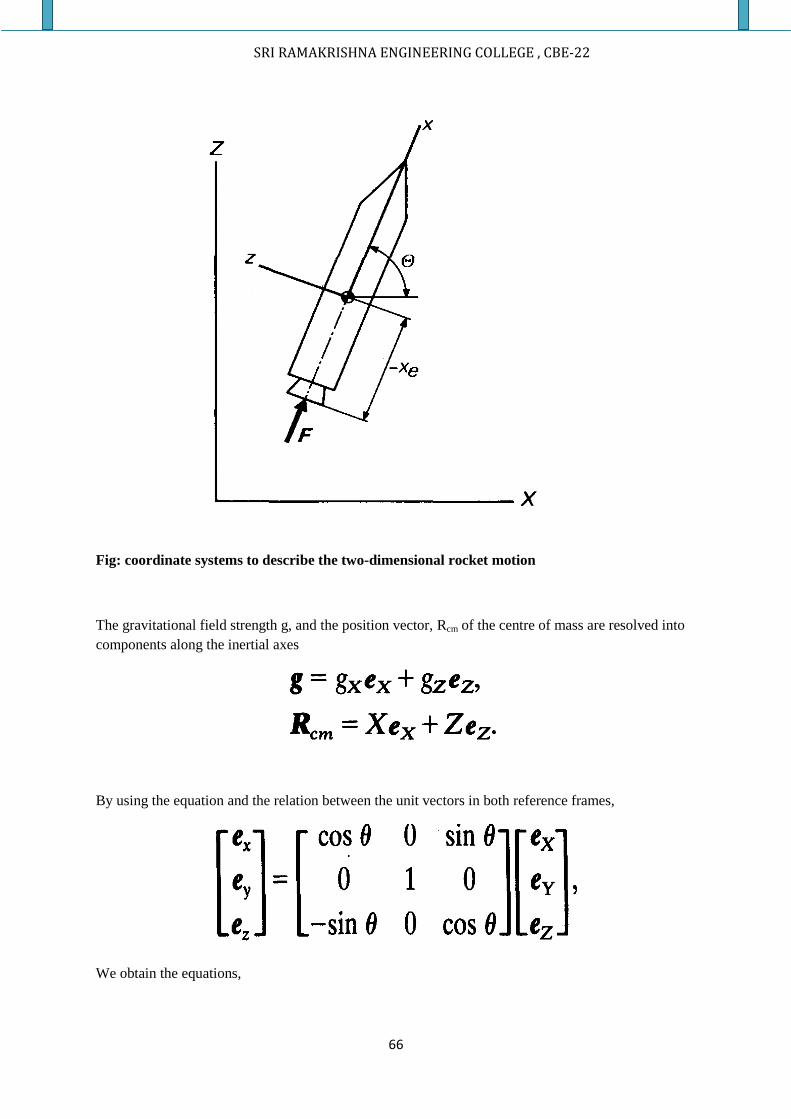
SRI RAMAKRISHNA ENGINEERING COLLEGE , CBE-22
66
Fig: coordinate systems to describe the two-dimensional rocket motion
The gravitational field strength g, and the position vector, Rcm of the centre of mass are resolved into
components along the inertial axes
By using the equation and the relation between the unit vectors in both reference frames,
We obtain the equations,
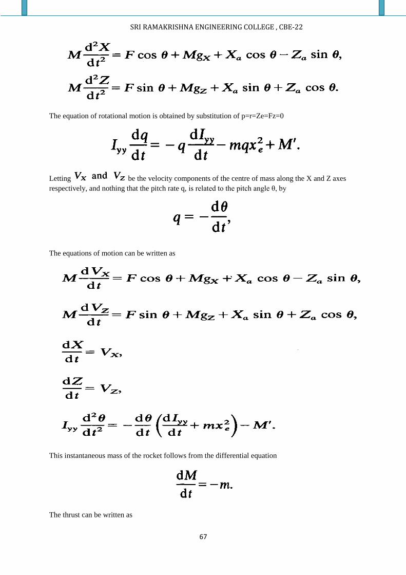
SRI RAMAKRISHNA ENGINEERING COLLEGE , CBE-22
67
The equation of rotational motion is obtained by substitution of p=r=Ze=Fz=0
Letting be the velocity components of the centre of mass along the X and Z axes
respectively, and nothing that the pitch rate q, is related to the pitch angle θ, by
The equations of motion can be written as
This instantaneous mass of the rocket follows from the differential equation
The thrust can be written as
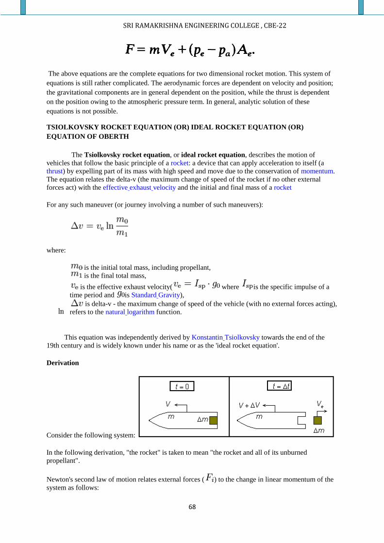
SRI RAMAKRISHNA ENGINEERING COLLEGE , CBE-22
68
The above equations are the complete equations for two dimensional rocket motion. This system of
equations is still rather complicated. The aerodynamic forces are dependent on velocity and position;
the gravitational components are in general dependent on the position, while the thrust is dependent
on the position owing to the atmospheric pressure term. In general, analytic solution of these
equations is not possible.
TSIOLKOVSKY ROCKET EQUATION (OR) IDEAL ROCKET EQUATION (OR)
EQUATION OF OBERTH
The Tsiolkovsky rocket equation, or ideal rocket equation, describes the motion of
vehicles that follow the basic principle of a rocket: a device that can apply acceleration to itself (a
thrust) by expelling part of its mass with high speed and move due to the conservation of momentum.
The equation relates the delta-v (the maximum change of speed of the rocket if no other external
forces act) with the effective exhaust velocity and the initial and final mass of a rocket
For any such maneuver (or journey involving a number of such maneuvers):
where:
is the initial total mass, including propellant,
is the final total mass,
is the effective exhaust velocity( where is the specific impulse of a
time period and is Standard Gravity),
is delta-v - the maximum change of speed of the vehicle (with no external forces acting),
refers to the natural logarithm function.
This equation was independently derived by Konstantin Tsiolkovsky towards the end of the
19th century and is widely known under his name or as the 'ideal rocket equation'.
Derivation
Consider the following system:
In the following derivation, "the rocket" is taken to mean "the rocket and all of its unburned
propellant".
Newton's second law of motion relates external forces ( ) to the change in linear momentum of the
system as follows:
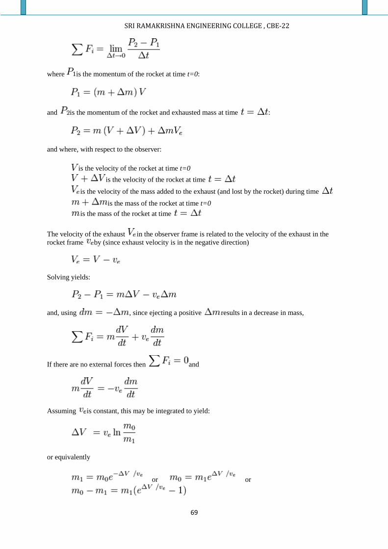
SRI RAMAKRISHNA ENGINEERING COLLEGE , CBE-22
69
where is the momentum of the rocket at time t=0:
and is the momentum of the rocket and exhausted mass at time :
and where, with respect to the observer:
is the velocity of the rocket at time t=0
is the velocity of the rocket at time
is the velocity of the mass added to the exhaust (and lost by the rocket) during time
is the mass of the rocket at time t=0
is the mass of the rocket at time
The velocity of the exhaust in the observer frame is related to the velocity of the exhaust in the
rocket frame by (since exhaust velocity is in the negative direction)
Solving yields:
and, using , since ejecting a positive results in a decrease in mass,
If there are no external forces then and
Assuming is constant, this may be integrated to yield:
or equivalently
or or
SRI RAMAKRISHNA ENGINEERING COLLEGE , CBE-22
70
where is the initial total mass including propellant, the final total mass, and the velocity of
the rocket exhaust with respect to the rocket (the specific impulse, or, if measured in time, that
multiplied by gravity-on-Earth acceleration).
The value is the total mass of propellant expended, and hence:
where is the mass fraction (the part of the initial total mass that is spent as reaction mass).
Applicability
The rocket equation captures the essentials of rocket flight physics in a single short equation. It also
holds true for rocket-like reaction vehicles whenever the effective exhaust velocity is constant; and
can be summed or integrated when the effective exhaust velocity varies. It does not apply to non
rocket systems, such as aero braking, gun launches, space elevators, launch loops, and in tether
propulsion.
ROCKET PARAMETERS:
The mass ratio is the very important parameter in determining the ideal velocity of the rocket. Mass
ratio is defined as the ratio between the initial and final mass of the rocket.
Mass ratio = M0/M1
Next to the mass ratio we can also define some of the other dimensionless quantities.
We divide the initial mass (M0) of the rocket into three parts. They are,
1. Payload mass(Mu)
2. Propellant mass(Mp)
3. Structural mass (Mc)
Therefore we also define the initial mass and final mass as,
Initial mass,M0 = Mu+Mp+Mc
Final mass, M1 = Mu +Mc
1. PAYLOAD MASS (λ):
Payload ratio is defined as the ratio between payload mass to the initial mass of the rocket. It
is defined by the symbol λ.
SRI RAMAKRISHNA ENGINEERING COLLEGE , CBE-22
71
2. PROPELLANT RATIO (Φ):
Propellant ratio is defined as the ratio between useful propellant mass to the initial mass of the
rocket.
3. STRUCTURAL EFFICIENCY (ε):
Structural efficiency is defined as the ratio of structural mass to the summation of propellant
mass and structural mass. It is denoted by the symbol ɛ.
NOTE:
1. Mass ratio ˄, is always larger than 1.But in gravitation less field it is less than 1.
2. The payload ratio, structural efficiency and propellant ratio are always less than 1.
3. In general the range of these parameters for a single stage rocket is,
It can be checked easily that the various parameters are related by,
Apart from the mass parameters, the two other rocket parameters which relate the mass and thrust are,
1. The Specific thrust (β):
SRI RAMAKRISHNA ENGINEERING COLLEGE , CBE-22
72
2. The thrust-to-weight ratio(ψ0):
THE BURNOUT RANGE:
Burnout is defined as the termination of a rocket operation because of fuel exhaustion or
shut off.
The distance covered at a time t is given by,
In order to evaluate the above integral we have to know V as a function of time, m=m(t), has
to be known.
For burnout range we have to derive expressions for two different propellant
consumptions.
The first one yields a constant thrust and the second one yields the constant specific
thrust.
There are two cases in case of burn out range. They are,
1. Constant Thrust
2. Constant Specific Thrust
CASE1: CONSTANT THRUST:
In this case the propellant consumption is,
Consequently the instantaneous mass of the rocket during thrusting is given by,
The burning time tb follows from,
SRI RAMAKRISHNA ENGINEERING COLLEGE , CBE-22
73
Solve the above equation for getting tb using mass ratio and thrust to weight ratio,
which yields
IMPULSIVE SHOT:
For a fixed ψ0 the burning time increases with increasing specific
impulse, and increasing mass ratio˄.
The burning time decreases if ψ0 increases, and tb→0 if ψ0→∞.
In that case all the propellant is consumed instantaneously. This is
called an impulsive shot.
The velocity as a function of time is given by (for zero initial velocity)
Substitute the velocity equation in eqn no1, and evaluate the integral which
leads to
Introduce the range function p(t), which is defined as,
Ad using thrust to weight ratio equation, the range can be written as,
The burnout range i.e, the distance covered at t=tb, then,
Where,

SRI RAMAKRISHNA ENGINEERING COLLEGE , CBE-22
74
Therefore the burnout range is given by,
We see that the burnout range is proportional to the square of the specific
impulse and inversely proportional to the thrust to weight ratio.
For an impulsive shot ∆sb =0. If ˄→∞ the function pb approaches unity.
DIMENSIONLESS ACCELERATION:
It is defined as,
This equals the specific thrust and is increasing monotonically from ψ0 to ˄ψ0 at
burnout.
The dimensionless burnout range in free space
The figure gives the dimensionless burnout range, ∆sb/g0Isp
2, as a function of ˄and also
depicts the range as a function of instantaneous mass ratio M0/ (M0-m0t).
CASE 2: CONSTANT SPECIFIC THRUST:
In this case,
SRI RAMAKRISHNA ENGINEERING COLLEGE , CBE-22
75
So
By differentiating the above equation, the propellant consumption as a function of time is
found to be,
And the burning time follows from the eqn 2,
In this case, the specific impulse can be interpreted as a burning time, namely the burning
time of the rocket with mass ratio˄=e and a constant specific thrust of unity. As the
acceleration is constant and equal to g0β0, velocity and range are given by
And thus the burnout
It can be verified easily that, in the case of constant specific thrust, burning time and burnout
range are larger than the corresponding quantities in the case of constant thrust with the same
initial specific thrust.
SRI RAMAKRISHNA ENGINEERING COLLEGE , CBE-22
76
ROCKET MOTION IN A HOMOGENEOUS GRAVITATIONAL FIELD:
Homogeneous gravitational field is defined as the gravitational field at which the field
strength g, is constant throughout.
If we consider the earth locally as being flat, the local gravitational field may be
considered homogeneous. Actually the earth is nearly spherical and its gravitational field can
be approximated very well by a central inverse square field.
However as long as the altitude and range are small relative to the mean earth’s radius,
the earth may be considered flat and the field strength can be approximated very well by a
constant.
For small rockets, such as sounding rockets and tactical missiles this approximation
yields good results. For launch vehicles and intercontinental ballistic missiles the powered
flight trajectory of the first stages can also be calculated by good approximation with the flat
earth assumption.
For upper stages, however, the velocity will be so large that the flat earth
approximation will lead to unacceptable deviations from the real trajectory. However, as most
part of this trajectory is a coast phase, the trajectory can be approximated by a ballistic one
and can be determined analytically in case of spherical earth.
If we choose the X-axis of the inertial system to coincide with the flat earth surface and
the Z-axis vertical, then gx=0 and gz= -g0, where it is assumed that motion takes place near the
surface of the earth. Then the equation of transitional motion become,
SRI RAMAKRISHNA ENGINEERING COLLEGE , CBE-22
77
Then the thrust is given by,
There are two cases in case of homogeneous gravitational field. They are,
1. Vertical Flight
2. Inclined Flight (or) Constant Pitch Angle
CASE1: VERTICAL FLIGHT:
If during the whole flight θ=900, and if we have zero initial horizontal velocity, the
trajectory will be straight line parallel to the z-axis. In that case Vz equals to the total
velocity V, and the equation of motion simplifies to
As initial conditions we will choose a zero velocity and altitude at t=0. Equation 1 can be
integrated independently of the mass flow program, leading to
We see that, in order to determine V as a function of time. Even the burn out velocity in this
case is dependent on the thrust program because the burning time depends on it. Again we
will assume a constant thrust, in which case the mass flow is given by,
For this case the burning time is already derived in burn out range derivation. Then we find the
velocity as a function of time
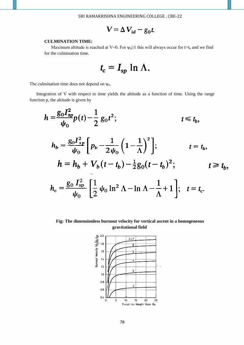
SRI RAMAKRISHNA ENGINEERING COLLEGE , CBE-22
78
CULMINATION TIME:
Maximum altitude is reached at V=0. For ψ0≥1 this will always occur for t>tb and we find
for the culmination time.
The culmination time does not depend on ψ0.
Integration of V with respect to time yields the altitude as a function of time. Using the range
function p, the altitude is given by
Fig: The dimensionless burnout velocity for vertical ascent in a homogeneous
gravitational field

SRI RAMAKRISHNA ENGINEERING COLLEGE , CBE-22
79
Fig: The burnout and culmination altitudes for vertical ascent in a homogeneous
gravitational field and in vacuum
From the figure above there is an optimal thrust to weight ratio, yielding a maximum value of the
burnout altitude. The optimal value of ψ0 is found by differentiating the expression for hb with respect
to ψ0 and setting the result equal to zero. Apart from the solution ψ0→∞, which yields a maximum
burnout altitude, this leads to
The corresponding value of burnout altitude then is,
The maximum culmination altitude is given by,
CASE 2: CONSTANT PITCH ANGLE:
For constant pitch angle case we have to consider the equation of motion with θ=θ0. For
simplicity , we assume t=0, in the origin of the inertial frame, with zero initial velocity. The
equations for the velocity components can be integrated directly yielding,
SRI RAMAKRISHNA ENGINEERING COLLEGE , CBE-22
80
From burn out range derivation we derive burn out velocity. From that we use burn out
velocity ,
We see that gravity losses increase with increasing pitch angle θ0, and increasing burning time
tb.
The flight path angle between the velocity vector and the X-axis and positive if Vz is
positive follows from,
The angle of attack, i.e. the angle between the longitudinal axis of the roc ket and the velocity
vector is given by,
By using tanγ equation it can be derived that,
We see that, in general flight path angle and angle of attack will not be constant and the
trajectory will be curved. Only in the case that ln M0/M1 is proportional to the flight path
angle and the angle of attack is constant and the resulting trajectory will be a straight line.
If we consider a constant thrust then the velocity components, the flight path angle and
the angle of attack follows a function of time by substitution of
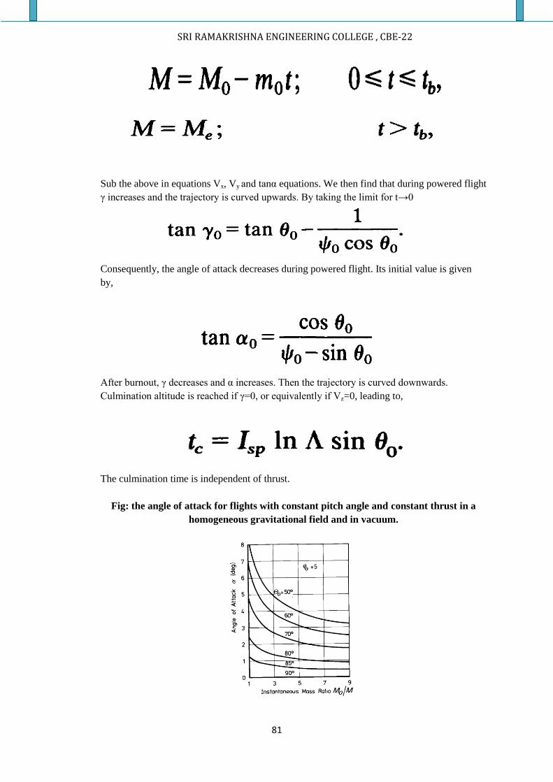
SRI RAMAKRISHNA ENGINEERING COLLEGE , CBE-22
81
Sub the above in equations Vx, Vy and tanα equations. We then find that during powered flight
γ increases and the trajectory is curved upwards. By taking the limit for t→0
Consequently, the angle of attack decreases during powered flight. Its initial value is given
by,
After burnout, γ decreases and α increases. Then the trajectory is curved downwards.
Culmination altitude is reached if γ=0, or equivalently if Vz=0, leading to,
The culmination time is independent of thrust.
Fig: the angle of attack for flights with constant pitch angle and constant thrust in a
homogeneous gravitational field and in vacuum.
SRI RAMAKRISHNA ENGINEERING COLLEGE , CBE-22
82
During powered flight, the coordinates are determined by,
The position at burn out is given by,
After burnout the position follows from
The coordinates for the culmination point are obtained by substitution of t=tc in the above
equations.
GRAVITY TURN TRAJECTORY (OR) ZERO LIFT TRAJECTORY:
To reduce the aerodynamic forces on a rocket during its flight through the
atmosphere, one will endeavour to keep the angle of attack as small as possible. For simple
aerodynamically stabilized vehicles, this is accomplished by fixed fins.
Vehicle that are mechanically stabilized or more or less complicated control systems
to generate the moments necessary to keep the angle of attack as small as possible. This is of
course not the case for aerodynamically controlled rockets during manoeuvring.
SRI RAMAKRISHNA ENGINEERING COLLEGE , CBE-22
83
For launch vehicles, ICBMs and uncontrolled aerodynamically stabilized rockets
we can say that the flight through the atmosphere takes place with zero angle of attack. In that
case there is no lift and the curvature of trajectory is solely due to gravity, and hence the name
gravity turn or zero lift trajectory
.
As the angle of attack is zero, the flight path angle equals the pitch angle,
Then the equation of motion become,
Where
It is convenient in this case to use the total velocity V and the flight path angle γas dependent
variables instead of Vx and Vz and the summation yields,
The differential equation for γ is found by multiplication of eqn of motion eqn by Vz and by
Vx and subtract the results we get,
The equations for the gravity turn, in general, cannot be solved analytically. However some
special cases exist which allow for analytical solutions. These are constant specific thrust and
constant pitch rate.
SRI RAMAKRISHNA ENGINEERING COLLEGE , CBE-22
84
CASE 1: CONSTANT SPECIFIC THRUST:
β = β0. In this case the the equations of motion become
Elimination of t from the above equations leads to
Integration of the above equation leads to
We now define a velocity factor, Ӷ
If V0 and γ0 are initial velocity and initial flight path angle respectively, then the above two
equations can be combined and can be written as,
KICK ANGLE:
In preliminary trajectory calculations the pitch over period is represented mathematically
by an instantaneous rotation of both vehicle and velocity vector over an angle δ0, called the
kick angle. The flight path angle then is,
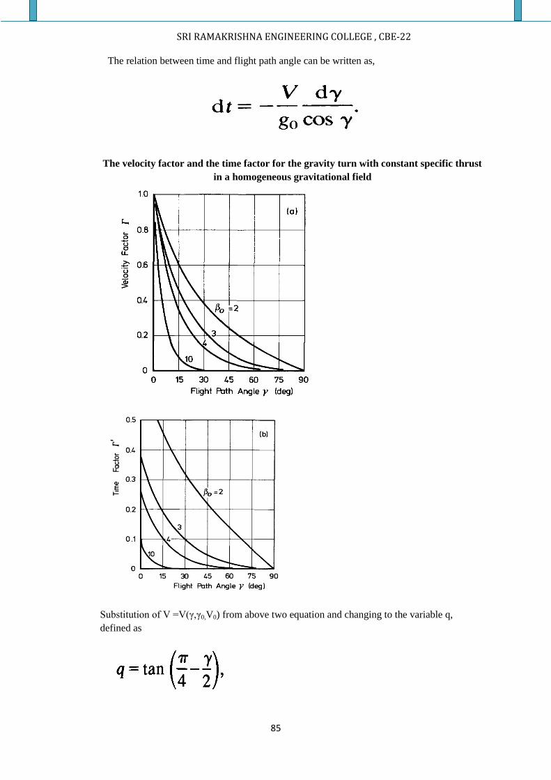
SRI RAMAKRISHNA ENGINEERING COLLEGE , CBE-22
85
The relation between time and flight path angle can be written as,
The velocity factor and the time factor for the gravity turn with constant specific thrust
in a homogeneous gravitational field
Substitution of V =V(γ,γ0,V0) from above two equation and changing to the variable q,
defined as
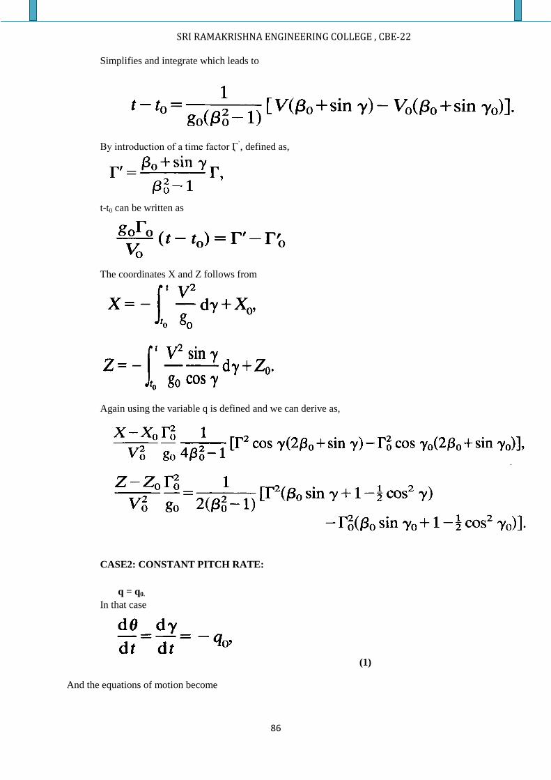
SRI RAMAKRISHNA ENGINEERING COLLEGE , CBE-22
86
Simplifies and integrate which leads to
By introduction of a time factor Ӷ
’, defined as,
t-t0 can be written as
The coordinates X and Z follows from
Again using the variable q is defined and we can derive as,
CASE2: CONSTANT PITCH RATE:
q = q0.
In that case
(1)
And the equations of motion become
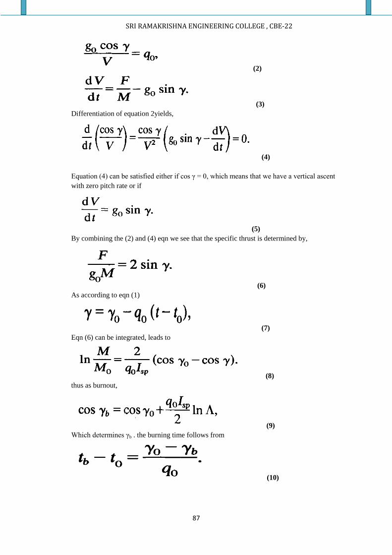
SRI RAMAKRISHNA ENGINEERING COLLEGE , CBE-22
87
(2)
(3)
Differentiation of equation 2yields,
(4)
Equation (4) can be satisfied either if cos γ = 0, which means that we have a vertical ascent
with zero pitch rate or if
(5)
By combining the (2) and (4) eqn we see that the specific thrust is determined by,
(6)
As according to eqn (1)
(7)
Eqn (6) can be integrated, leads to
(8)
thus as burnout,
(9)
Which determines γb . the burning time follows from
(10)
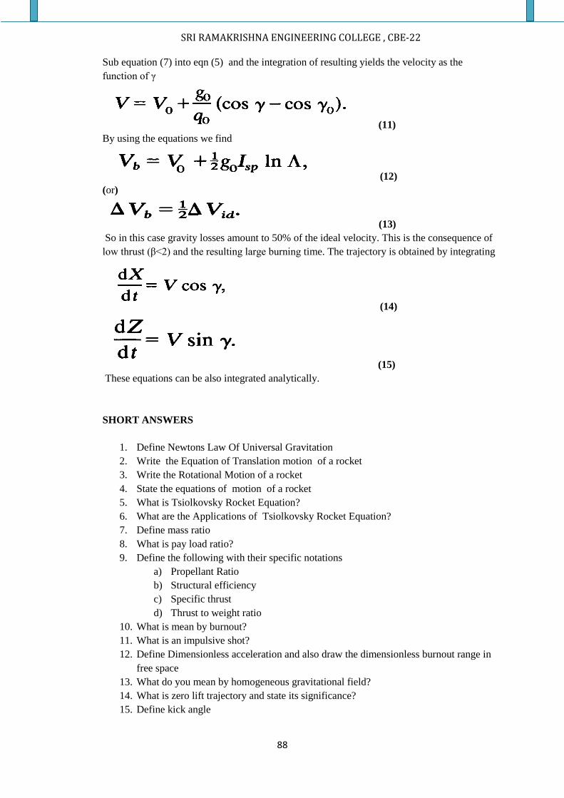
SRI RAMAKRISHNA ENGINEERING COLLEGE , CBE-22
88
Sub equation (7) into eqn (5) and the integration of resulting yields the velocity as the
function of γ
(11)
By using the equations we find
(12)
(or)
(13)
So in this case gravity losses amount to 50% of the ideal velocity. This is the consequence of
low thrust (β<2) and the resulting large burning time. The trajectory is obtained by integrating
(14)
(15)
These equations can be also integrated analytically.
SHORT ANSWERS
1. Define Newtons Law Of Universal Gravitation
2. Write the Equation of Translation motion of a rocket
3. Write the Rotational Motion of a rocket
4. State the equations of motion of a rocket
5. What is Tsiolkovsky Rocket Equation?
6. What are the Applications of Tsiolkovsky Rocket Equation?
7. Define mass ratio
8. What is pay load ratio?
9. Define the following with their specific notations
a) Propellant Ratio
b) Structural efficiency
c) Specific thrust
d) Thrust to weight ratio
10. What is mean by burnout?
11. What is an impulsive shot?
12. Define Dimensionless acceleration and also draw the dimensionless burnout range in
free space
13. What do you mean by homogeneous gravitational field?
14. What is zero lift trajectory and state its significance?
15. Define kick angle
SRI RAMAKRISHNA ENGINEERING COLLEGE , CBE-22
89
ANSWER IN DETAIL:
1. State the equations of motion of a rocket
2. Derive the equation of Oberth in terms of ideal velocity and mass ratio of a rocket
(Or)
Derive Tsiolkovsky Rocket equation (or) ideal rocket equation in terms of mass ratio
3. Derive an expression for burnout range in terms of specific impulse, mass ratio and
thrust to weight ratio of a rocket. Assume the rocket develops a constant thrust
4. Derive an expression for the burnout range in case of constant specific thrust
5. Obtain an expression for burnout altitude and culmination altitude attained by a
sounding rocket. Thrust developed by the rocket is constant. Aerodynamic effects can
be neglected. Assume the rocket motion is in homogeneous gravitational field
6. Explain what is homogeneous gravitational field and also obtain an expression for a
rocket in vertical flight
7. A rocket unit undergoes an inclined trajectory with constant pitch angle. The rocket
develops constant thrust and its motion is in a homogeneous gravitational field.
Derive expressions for burnout velocity and burnout altitude and culmination time.
Show that the restical component of velocity is zero at culmination. Neglect the
aerodynamic forces in the derivation
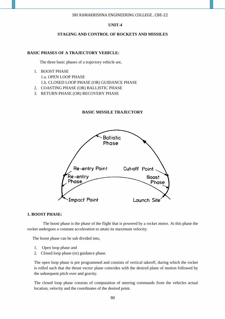
SRI RAMAKRISHNA ENGINEERING COLLEGE , CBE-22
90
UNIT-4
STAGING AND CONTROL OF ROCKETS AND MISSILES
BASIC PHASES OF A TRAJECTORY VEHICLE:
The three basic phases of a trajectory vehicle are,
1. BOOST PHASE
1.a. OPEN LOOP PHASE
1.b. CLOSED LOOP PHASE (OR) GUIDANCE PHASE
2. COASTING PHASE (OR) BALLISTIC PHASE
3. RETURN PHASE (OR) RECOVERY PHASE
BASIC MISSILE TRAJECTORY
1. BOOST PHASE:
The boost phase is the phase of the flight that is powered by a rocket motor. At this phase the
rocket undergoes a constant acceleration to attain its maximum velocity.
The boost phase can be sub divided into,
1. Open loop phase and
2. Closed loop phase (or) guidance phase.
The open loop phase is pre programmed and consists of vertical takeoff, during which the rocket
is rolled such that the thrust vector plane coincides with the desired plane of motion followed by
the subsequent pitch over and gravity.
The closed loop phase consists of computation of steering commands from the vehicles actual
location, velocity and the coordinates of the desired point.
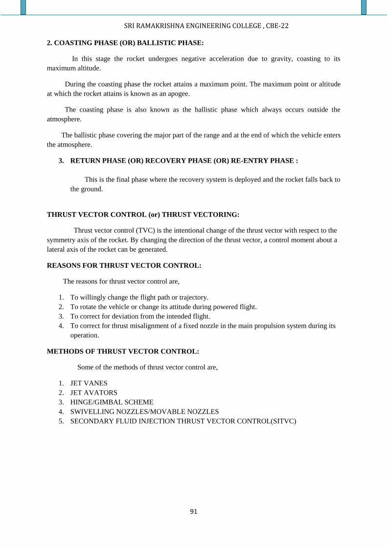
SRI RAMAKRISHNA ENGINEERING COLLEGE , CBE-22
91
2. COASTING PHASE (OR) BALLISTIC PHASE:
In this stage the rocket undergoes negative acceleration due to gravity, coasting to its
maximum altitude.
During the coasting phase the rocket attains a maximum point. The maximum point or altitude
at which the rocket attains is known as an apogee.
The coasting phase is also known as the ballistic phase which always occurs outside the
atmosphere.
The ballistic phase covering the major part of the range and at the end of which the vehicle enters
the atmosphere.
3. RETURN PHASE (OR) RECOVERY PHASE (OR) RE-ENTRY PHASE :
This is the final phase where the recovery system is deployed and the rocket falls back to
the ground.
THRUST VECTOR CONTROL (or) THRUST VECTORING:
Thrust vector control (TVC) is the intentional change of the thrust vector with respect to the
symmetry axis of the rocket. By changing the direction of the thrust vector, a control moment about a
lateral axis of the rocket can be generated.
REASONS FOR THRUST VECTOR CONTROL:
The reasons for thrust vector control are,
1. To willingly change the flight path or trajectory.
2. To rotate the vehicle or change its attitude during powered flight.
3. To correct for deviation from the intended flight.
4. To correct for thrust misalignment of a fixed nozzle in the main propulsion system during its
operation.
METHODS OF THRUST VECTOR CONTROL:
Some of the methods of thrust vector control are,
1. JET VANES
2. JET AVATORS
3. HINGE/GIMBAL SCHEME
4. SWIVELLING NOZZLES/MOVABLE NOZZLES
5. SECONDARY FLUID INJECTION THRUST VECTOR CONTROL(SITVC)
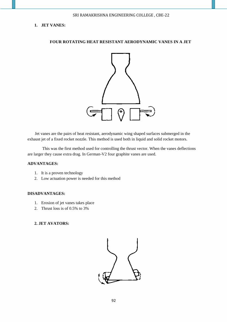
SRI RAMAKRISHNA ENGINEERING COLLEGE , CBE-22
92
1. JET VANES:
FOUR ROTATING HEAT RESISTANT AERODYNAMIC VANES IN A JET
Jet vanes are the pairs of heat resistant, aerodynamic wing shaped surfaces submerged in the
exhaust jet of a fixed rocket nozzle. This method is used both in liquid and solid rocket motors.
This was the first method used for controlling the thrust vector. When the vanes deflections
are larger they cause extra drag. In German-V2 four graphite vanes are used.
ADVANTAGES:
1. It is a proven technology
2. Low actuation power is needed for this method
DISADVANTAGES:
1. Erosion of jet vanes takes place
2. Thrust loss is of 0.5% to 3%
2. JET AVATORS:
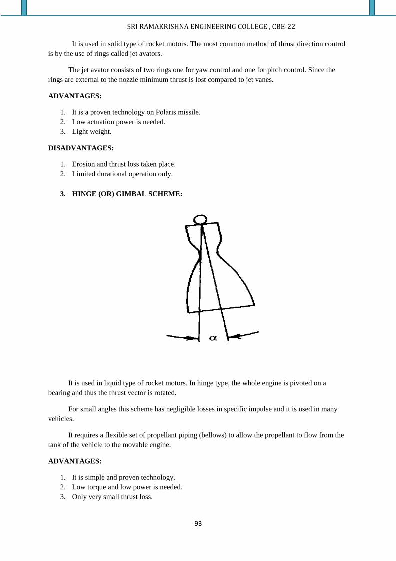
SRI RAMAKRISHNA ENGINEERING COLLEGE , CBE-22
93
It is used in solid type of rocket motors. The most common method of thrust direction control
is by the use of rings called jet avators.
The jet avator consists of two rings one for yaw control and one for pitch control. Since the
rings are external to the nozzle minimum thrust is lost compared to jet vanes.
ADVANTAGES:
1. It is a proven technology on Polaris missile.
2. Low actuation power is needed.
3. Light weight.
DISADVANTAGES:
1. Erosion and thrust loss taken place.
2. Limited durational operation only.
3. HINGE (OR) GIMBAL SCHEME:
It is used in liquid type of rocket motors. In hinge type, the whole engine is pivoted on a
bearing and thus the thrust vector is rotated.
For small angles this scheme has negligible losses in specific impulse and it is used in many
vehicles.
It requires a flexible set of propellant piping (bellows) to allow the propellant to flow from the
tank of the vehicle to the movable engine.
ADVANTAGES:
1. It is simple and proven technology.
2. Low torque and low power is needed.
3. Only very small thrust loss.
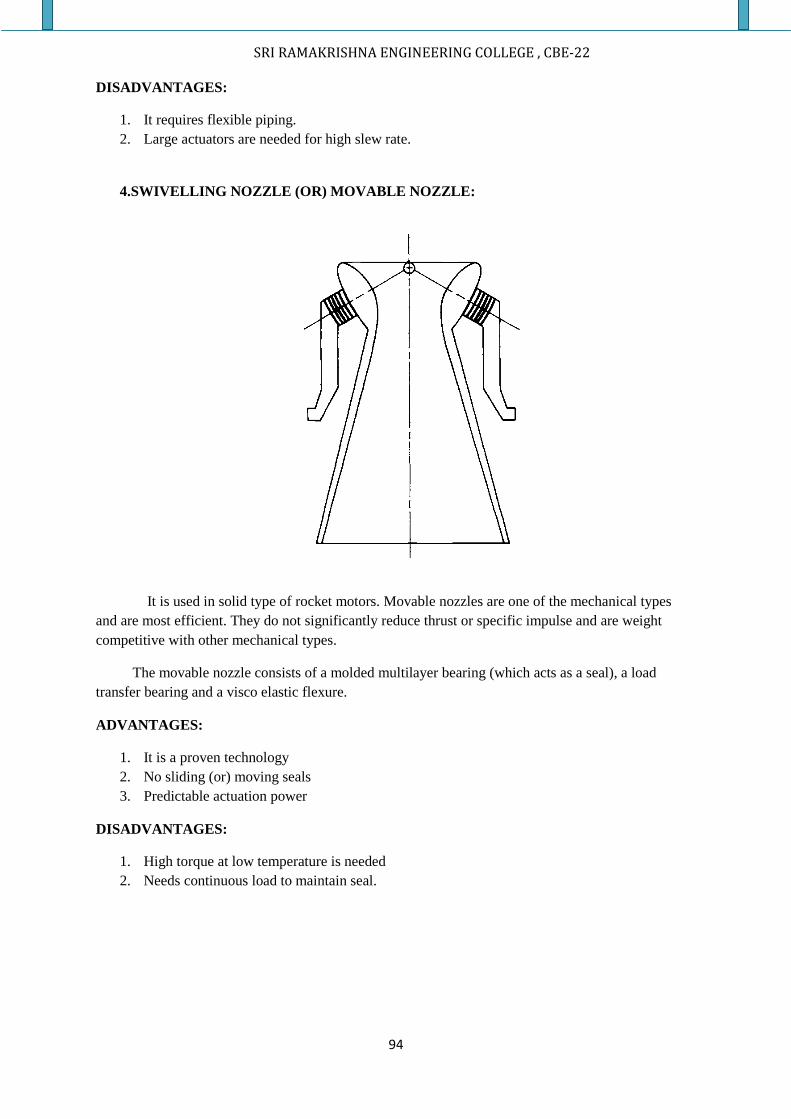
SRI RAMAKRISHNA ENGINEERING COLLEGE , CBE-22
94
DISADVANTAGES:
1. It requires flexible piping.
2. Large actuators are needed for high slew rate.
4.SWIVELLING NOZZLE (OR) MOVABLE NOZZLE:
It is used in solid type of rocket motors. Movable nozzles are one of the mechanical types
and are most efficient. They do not significantly reduce thrust or specific impulse and are weight
competitive with other mechanical types.
The movable nozzle consists of a molded multilayer bearing (which acts as a seal), a load
transfer bearing and a visco elastic flexure.
ADVANTAGES:
1. It is a proven technology
2. No sliding (or) moving seals
3. Predictable actuation power
DISADVANTAGES:
1. High torque at low temperature is needed
2. Needs continuous load to maintain seal.
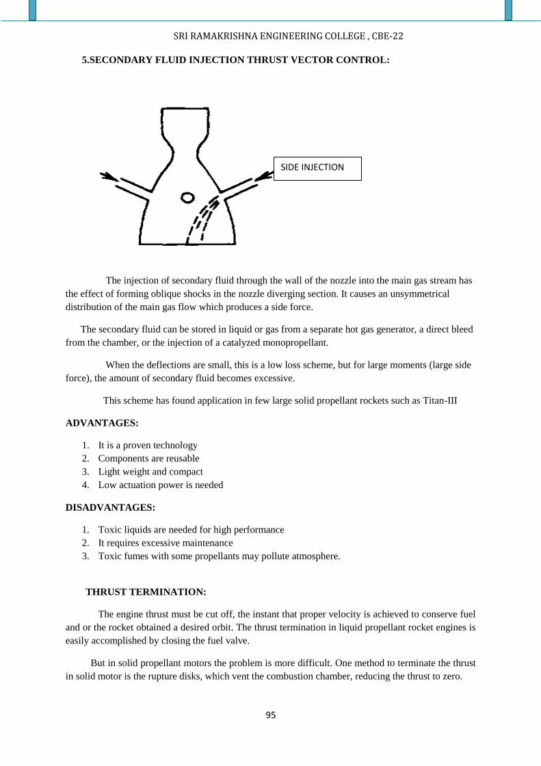
SRI RAMAKRISHNA ENGINEERING COLLEGE , CBE-22
95
5.SECONDARY FLUID INJECTION THRUST VECTOR CONTROL:
The injection of secondary fluid through the wall of the nozzle into the main gas stream has
the effect of forming oblique shocks in the nozzle diverging section. It causes an unsymmetrical
distribution of the main gas flow which produces a side force.
The secondary fluid can be stored in liquid or gas from a separate hot gas generator, a direct bleed
from the chamber, or the injection of a catalyzed monopropellant.
When the deflections are small, this is a low loss scheme, but for large moments (large side
force), the amount of secondary fluid becomes excessive.
This scheme has found application in few large solid propellant rockets such as Titan-III
ADVANTAGES:
1. It is a proven technology
2. Components are reusable
3. Light weight and compact
4. Low actuation power is needed
DISADVANTAGES:
1. Toxic liquids are needed for high performance
2. It requires excessive maintenance
3. Toxic fumes with some propellants may pollute atmosphere.
THRUST TERMINATION:
The engine thrust must be cut off, the instant that proper velocity is achieved to conserve fuel
and or the rocket obtained a desired orbit. The thrust termination in liquid propellant rocket engines is
easily accomplished by closing the fuel valve.
But in solid propellant motors the problem is more difficult. One method to terminate the thrust
in solid motor is the rupture disks, which vent the combustion chamber, reducing the thrust to zero.
SIDE INJECTION
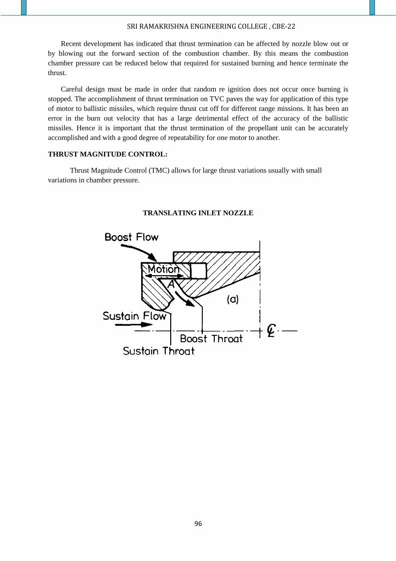
SRI RAMAKRISHNA ENGINEERING COLLEGE , CBE-22
96
Recent development has indicated that thrust termination can be affected by nozzle blow out or
by blowing out the forward section of the combustion chamber. By this means the combustion
chamber pressure can be reduced below that required for sustained burning and hence terminate the
thrust.
Careful design must be made in order that random re ignition does not occur once burning is
stopped. The accomplishment of thrust termination on TVC paves the way for application of this type
of motor to ballistic missiles, which require thrust cut off for different range missions. It has been an
error in the burn out velocity that has a large detrimental effect of the accuracy of the ballistic
missiles. Hence it is important that the thrust termination of the propellant unit can be accurately
accomplished and with a good degree of repeatability for one motor to another.
THRUST MAGNITUDE CONTROL:
Thrust Magnitude Control (TMC) allows for large thrust variations usually with small
variations in chamber pressure.
TRANSLATING INLET NOZZLE
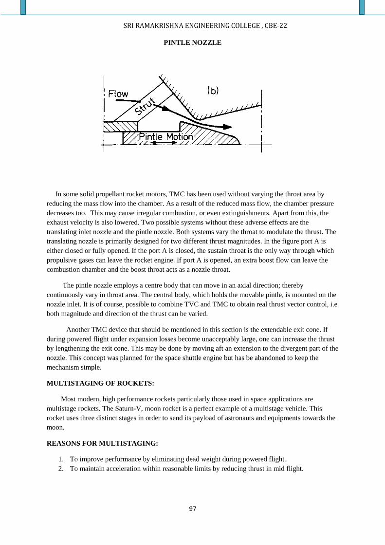
SRI RAMAKRISHNA ENGINEERING COLLEGE , CBE-22
97
PINTLE NOZZLE
In some solid propellant rocket motors, TMC has been used without varying the throat area by
reducing the mass flow into the chamber. As a result of the reduced mass flow, the chamber pressure
decreases too. This may cause irregular combustion, or even extinguishments. Apart from this, the
exhaust velocity is also lowered. Two possible systems without these adverse effects are the
translating inlet nozzle and the pintle nozzle. Both systems vary the throat to modulate the thrust. The
translating nozzle is primarily designed for two different thrust magnitudes. In the figure port A is
either closed or fully opened. If the port A is closed, the sustain throat is the only way through which
propulsive gases can leave the rocket engine. If port A is opened, an extra boost flow can leave the
combustion chamber and the boost throat acts as a nozzle throat.
The pintle nozzle employs a centre body that can move in an axial direction; thereby
continuously vary in throat area. The central body, which holds the movable pintle, is mounted on the
nozzle inlet. It is of course, possible to combine TVC and TMC to obtain real thrust vector control, i.e
both magnitude and direction of the thrust can be varied.
Another TMC device that should be mentioned in this section is the extendable exit cone. If
during powered flight under expansion losses become unacceptably large, one can increase the thrust
by lengthening the exit cone. This may be done by moving aft an extension to the divergent part of the
nozzle. This concept was planned for the space shuttle engine but has be abandoned to keep the
mechanism simple.
MULTISTAGING OF ROCKETS:
Most modern, high performance rockets particularly those used in space applications are
multistage rockets. The Saturn-V, moon rocket is a perfect example of a multistage vehicle. This
rocket uses three distinct stages in order to send its payload of astronauts and equipments towards the
moon.
REASONS FOR MULTISTAGING:
1. To improve performance by eliminating dead weight during powered flight.
2. To maintain acceleration within reasonable limits by reducing thrust in mid flight.
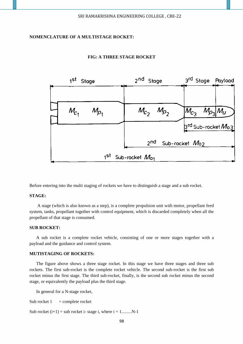
SRI RAMAKRISHNA ENGINEERING COLLEGE , CBE-22
98
NOMENCLATURE OF A MULTISTAGE ROCKET:
FIG: A THREE STAGE ROCKET
Before entering into the multi staging of rockets we have to distinguish a stage and a sub rocket.
STAGE:
A stage (which is also known as a step), is a complete propulsion unit with motor, propellant feed
system, tanks, propellant together with control equipment, which is discarded completely when all the
propellant of that stage is consumed.
SUB ROCKET:
A sub rocket is a complete rocket vehicle, consisting of one or more stages together with a
payload and the guidance and control system.
MUTISTAGING OF ROCKETS:
The figure above shows a three stage rocket. In this stage we have three stages and three sub
rockets. The first sub-rocket is the complete rocket vehicle. The second sub-rocket is the first sub
rocket minus the first stage. The third sub-rocket, finally, is the second sub rocket minus the second
stage, or equivalently the payload plus the third stage.
In general for a N-stage rocket,
Sub rocket 1 = complete rocket
Sub rocket (i+1) = sub rocket i- stage i, where i = 1.........N-1
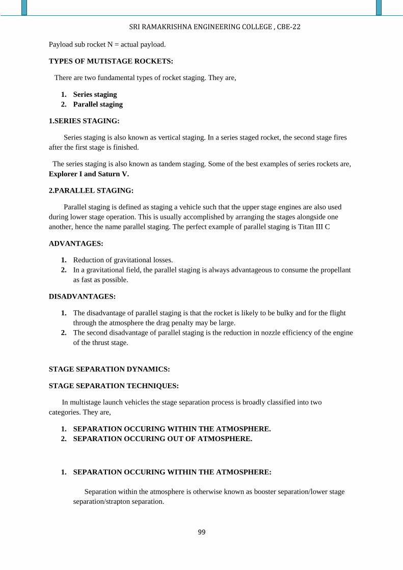
SRI RAMAKRISHNA ENGINEERING COLLEGE , CBE-22
99
Payload sub rocket N = actual payload.
TYPES OF MUTISTAGE ROCKETS:
There are two fundamental types of rocket staging. They are,
1. Series staging
2. Parallel staging
1.SERIES STAGING:
Series staging is also known as vertical staging. In a series staged rocket, the second stage fires
after the first stage is finished.
The series staging is also known as tandem staging. Some of the best examples of series rockets are,
Explorer I and Saturn V.
2.PARALLEL STAGING:
Parallel staging is defined as staging a vehicle such that the upper stage engines are also used
during lower stage operation. This is usually accomplished by arranging the stages alongside one
another, hence the name parallel staging. The perfect example of parallel staging is Titan III C
ADVANTAGES:
1. Reduction of gravitational losses.
2. In a gravitational field, the parallel staging is always advantageous to consume the propellant
as fast as possible.
DISADVANTAGES:
1. The disadvantage of parallel staging is that the rocket is likely to be bulky and for the flight
through the atmosphere the drag penalty may be large.
2. The second disadvantage of parallel staging is the reduction in nozzle efficiency of the engine
of the thrust stage.
STAGE SEPARATION DYNAMICS:
STAGE SEPARATION TECHNIQUES:
In multistage launch vehicles the stage separation process is broadly classified into two
categories. They are,
1. SEPARATION OCCURING WITHIN THE ATMOSPHERE.
2. SEPARATION OCCURING OUT OF ATMOSPHERE.
1. SEPARATION OCCURING WITHIN THE ATMOSPHERE:
Separation within the atmosphere is otherwise known as booster separation/lower stage
separation/strapton separation.
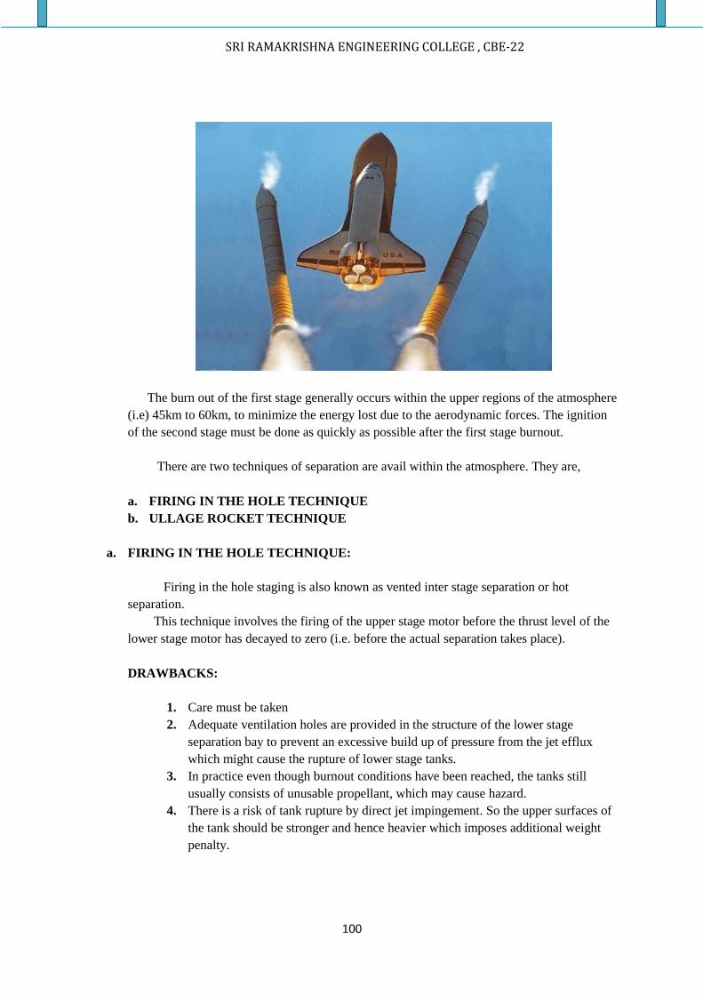
SRI RAMAKRISHNA ENGINEERING COLLEGE , CBE-22
100
The burn out of the first stage generally occurs within the upper regions of the atmosphere
(i.e) 45km to 60km, to minimize the energy lost due to the aerodynamic forces. The ignition
of the second stage must be done as quickly as possible after the first stage burnout.
There are two techniques of separation are avail within the atmosphere. They are,
a. FIRING IN THE HOLE TECHNIQUE
b. ULLAGE ROCKET TECHNIQUE
a. FIRING IN THE HOLE TECHNIQUE:
Firing in the hole staging is also known as vented inter stage separation or hot
separation.
This technique involves the firing of the upper stage motor before the thrust level of the
lower stage motor has decayed to zero (i.e. before the actual separation takes place).
DRAWBACKS:
1. Care must be taken
2. Adequate ventilation holes are provided in the structure of the lower stage
separation bay to prevent an excessive build up of pressure from the jet efflux
which might cause the rupture of lower stage tanks.
3. In practice even though burnout conditions have been reached, the tanks still
usually consists of unusable propellant, which may cause hazard.
4. There is a risk of tank rupture by direct jet impingement. So the upper surfaces of
the tank should be stronger and hence heavier which imposes additional weight
penalty.
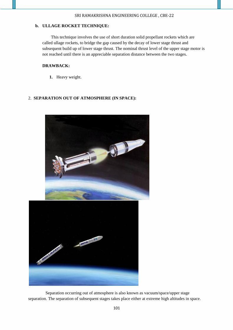
SRI RAMAKRISHNA ENGINEERING COLLEGE , CBE-22
101
b. ULLAGE ROCKET TECHNIQUE:
This technique involves the use of short duration solid propellant rockets which are
called ullage rockets, to bridge the gap caused by the decay of lower stage thrust and
subsequent build up of lower stage thrust. The nominal thrust level of the upper stage motor is
not reached until there is an appreciable separation distance between the two stages.
DRAWBACK:
1. Heavy weight.
2. SEPARATION OUT OF ATMOSPHERE (IN SPACE):
Separation occurring out of atmosphere is also known as vacuum/space/upper stage
separation. The separation of subsequent stages takes place either at extreme high altitudes in space.
SRI RAMAKRISHNA ENGINEERING COLLEGE , CBE-22
102
The problem of separation is relatively simplified when occurs in space because of absence
of aerodynamic forces but it does not mean as soon as burn out of lower stage occurs the ignition of
upper stage is initiated.
This separation technique involves two methods.
a. HELICAL COMPRESSION SPRING TECHNOLOGY
b. SHORT DURATION SOLID PROPELLANT TECHNOLOGY
a. HELICAL COMPRESSION SPRING TECHNOLOGY:
In this technology, separation may be obtained by a single compression spring
centrally located but in practice it was a large number of small springs located
symmetrically around the periphery. This is done in case of accommodation and
secondly to minimize the possibility of separation aborting through spring failure.
ADVANTAGES:
1. No separate command is needed for actuation
2. Highly reliable
DRAW BACK:
1. Much heavier when compared to other jettisoning system.
STAGE SEPARATION SYSTEMS:
Selection of stage separation system of launch vehicle is an extensive and exhaustive process.
The critical criterions are,
1. Joint rotation
2. Simultaneity
3. Reliability
4. Confinement of debris
5. Low shock levels
6. Weight
7. Cost.
The selected separation system should also meet all the functional requirements viz,
To achieve collision free separation of spent stages, ie, to establish clearances, between the separating bodies to ensure safe separation.
To provide the structural rigidity to attach the two bodies, the ability of the mechanism to withstand the flight loads encountered during flight that is structural integrity should be maintained.
To provide the means to severe the structural connection To impart positive separation velocity to the separation bodies. To impart minimum tip off rate to ongoing stage.
SRI RAMAKRISHNA ENGINEERING COLLEGE , CBE-22
103
Minimum shock transmission to the payload interfaces or the continuing stages
ELEMENTS (OR) SYSTEM FOR SEPARATION PROCESS:
Generally three basic elements are required for the functioning of separation process. They are, a) An actuator -to trigger the event usually electric or pyro based b) Release / Severance system for physical separation c) Jettisoning systems – to impart sufficient relative separation velocity
1) ACTUATOR: The actuator system as the word indicates actuates the triggering of the separation event. Thus, there is a delay between actuating the trigger and physical separation. Usually actuators are either a) Electric or b) Pyro based.
2) SEVERANCE/ RELEASE MACHANISMS: The severance/release systems impart physical separation to bodies; they are primarily 2 types; a) Mechanical systems & b) Pyro –technique devices. The design requirements for these systems are, Load carrying capability & compatibility with vehicle structure. Minimum electrical power for separation system. Minimum system weight & minimum volume. Minimum impulse & minimum tip off rates. High reliability, maintainability & long storage life. Survival of extremely high or low temperatures No contamination, debris free & survival of nuclear environment Safe handling & easy transportation.
A) Mechanical systems:
1. Ball & lock systems
Ball & lock system consists of upper & lower stages adopter rings held together by steel balls which in turn are held by a retainer ring. The retainer ring is provided with escape holes for balls. In the locked condition, the holes in the retainer ring are given an angular offset. During release, pyro-thrusters rotate the retainer ring which nullifies the offset. A stopper limits retainer ring rotation. Helical compression springs positioned between the flanges impart the required differential separation velocity. The lower stage outer ring is provided with through holes for the balls in the locked condition and the upper stages adapter ring is provided with conical ball seat, the radial component
SRI RAMAKRISHNA ENGINEERING COLLEGE , CBE-22
104
of the spring forces pushes the balls outward & releases the inner ring which ensures a clean separation. 2. Merman band /Clamp band: Multistage launch vehicles use clamp band joint for separation of upper stages & payload fairing. The necessary preload on clamp is given by tensioning two steel band segments placed over the clamps & connected by two tension bolts & nuts. In this type of joint the tapered interfaces flanges are held together by a series of aluminum clamps made of m250 steel circumferentially positioned. These clamps are preloaded using two steel band segments through two connecting bolts & nuts under tension pyro-cutters severe the connecting bolts when separation of the joint is required. .
2. COLLET MECHANISM:
The collect mechanism consists of a collect housing / cylinder with a piston holding the finger spread out in locked position. The mechanism can carry tensile loads when in locked position. When gas pressure is introduced in to the cylinder bore it acts on piston causing it to move forward & allowing the collect fingers to collapse due to their strain energy. This action permits separation of the vehicle from the spent stages. The device is capable of resisting high tensile loads and it can withstand the flight dynamic loads. It withstand a maximum temperature Gradient from 80 K 353 K .This system has to be protected from excessive aerodynamic Heating using cowlings & it has to be made waterproof for reliable operation. This system provides a debris free clean separation. B) PYRO SEPARATION DEVICES: These systems use pyro active element for imparting physical separation, two types are commonly employed they are, 1. Explosive Bolt: In the explosive bolt, the pyro charge is electrically initiated to severe the bolt at notches provided at separation planes. 2. Frangible nut: In frangible nut pyro activation causes the nut to open out and to release the studs engaged in nut threads. JETTISONING DEVICES: These systems have been used to provide the required relative separation velocity to the separating bodies. Energy required for jettisoning the systems are provide by employing anyone of the following type of thrusters, Spring thrusters Pneumatic thrusters Rocket thrusters
SRI RAMAKRISHNA ENGINEERING COLLEGE , CBE-22
105
Some of the Jettisoning systems usually employed in launch vehicles are described below:
1. SPRING THRUSTERS:
In spring thrusters, springs are packed and compressed to the required energy level. Disc springs depending or coil springs are employed depending on the jettisoning requirements; high energies are met with disc springs. The advantage of spring thrusters is that spring energy characteristics can be evalued prior to the assembly of the system and once assembled jettisoning spring force is always available for the function. Thus, separate command is not needed for the actuation and is highly reliable. To draw back with the spring thrusters is that they are heavier compared to the other types of jettisoning system. For smaller mass with lower energy requirements spring thrusters is an ideal choice whereas for large size boosters with higher jettisoning energy requirements their use is not recommended.
2. ROCKET THRUSTERS:
Rocket thrusters are used for jettisoning higher diameter massive boosters where the associated energy requirements are higher. The advantage of the rocket thrusters is that it can store much higher energy for a given weight of thrusters.
3. PNEUMATIC THRUSTERS:
In this type, the working medium is pressurized nitrogen gas. These thrusters are light in weight as the working medium is gas. The energy stored depends on the initial pressure and stroke length and there for by changing the pressure stored energy also can be varied. The pressure holding characteristics of the rolling diaphragm and joints is the limiting factor for the stored energy. Pneumatic thrusters do not require separate command for actuation as the jettisoning force is always available. I In pneumatic thrusters design must be simple, relatively steady operation process, less disturbances no exhaust ports are required and heat insulation is required.
SRI RAMAKRISHNA ENGINEERING COLLEGE , CBE-22
106
SRI RAMAKRISHNA ENGINEERING COLLEGE , CBE-22
107
SRI RAMAKRISHNA ENGINEERING COLLEGE , CBE-22
108
SRI RAMAKRISHNA ENGINEERING COLLEGE , CBE-22
109
ANSWER IN A SHORT:
1. What are the basic phases of a trajectory vehicle?
2. What is coasting phase with reference to the motion of a multistage launch vehicle?
3. What is meant by Thrust Vector Control?
4. What is the need for TVC?
5. What are the different types of Thrust Vector Controls?
6. What do understand by the term Thrust Magnitude Control
7. What is an apogee?
8. What is meant by thrust termination?
9. Is thrust termination easy in solid propellant engines or liquid engines? Justify.
10. What is a multistage rocket? What is the need for staging?
11. What are the types of multistage rockets? Give example.
12. Distinguish a stage and a sub-rocket
13. List out the various systems which are employed in stage separation
14. List the important stage separation techniques which are used in space
15. What are the important stage separation techniques which are used within the atmosphere?
ANSWER ELABORATELY:
1. What is a Thrust Vector Control? Explain the methods by which TVC can achieved.
2. Briefly explain what is meant by Thrust Magnitude Control.
3. Explain the various systems which are employed in stage separation.
4. What is a multistage rocket? Briefly explain its nomenclature with a neat sketch also explain
its types.
5. Elucidate the various stage separation techniques involved in stage separation dynamics.
6. Elucidate the various stage separation systems which are involved in stage separation
dynamics
7. Explain the optimization of a multistage rocket.
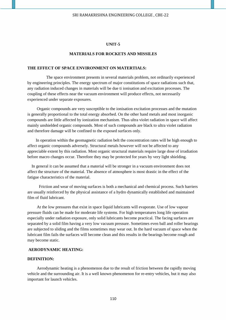
SRI RAMAKRISHNA ENGINEERING COLLEGE , CBE-22
110
UNIT-5
MATERIALS FOR ROCKETS AND MISSILES
THE EFFECT OF SPACE ENVIRONMENT ON MATERTIALS:
The space environment presents in several materials problem, not ordinarily experienced
by engineering principles. The energy spectrum of major constitutions of space radiations such that,
any radiation induced changes in materials will be due ti ionisation and excitation processes. The
coupling of these effects near the vacuum environment will produce effects, not necessarily
experienced under separate exposures.
Organic compounds are very susceptible to the ionisation excitation processes and the mutation
is generally proportional to the total energy absorbed. On the other hand metals and most inorganic
compounds are little affected by ionization mechanism. Thus ultra violet radiation in space will affect
mainly unshielded organic compounds. Most of such compounds are black to ultra violet radiation
and therefore damage will be confined to the exposed surfaces only.
In operation within the geomagnetic radiation belt the concentration rates will be high enough to
affect organic compounds adversely. Structural metals however will not be affected to any
appreciable extent by this radiation. Most organic structural materials require large dose of irradiation
before macro changes occur. Therefore they may be protected for years by very light shielding.
In general it can be assumed that a material will be stronger in a vacuum environment does not
affect the structure of the material. The absence of atmosphere is most drastic in the effect of the
fatigue characteristics of the material.
Friction and wear of moving surfaces is both a mechanical and chemical process. Such barriers
are usually reinforced by the physical assistance of a hydro dynamically established and maintained
film of fluid lubricant.
At the low pressures that exist in space liquid lubricants will evaporate. Use of low vapour
pressure fluids can be made for moderate life systems. For high temperatures long life operation
especially under radiation exposure, only solid lubricants become practical. The facing surfaces are
separated by a solid film having a very low vacuum pressure. Sometimes even ball and roller bearings
are subjected to sliding and the films sometimes may wear out. In the hard vacuum of space when the
lubricant film fails the surfaces will become clean and this results in the bearings become rough and
may become static.
AERODYNAMIC HEATING:
DEFINITION:
Aerodynamic heating is a phenomenon due to the result of friction between the rapidly moving
vehicle and the surrounding air. It is a well known phenomenon for re-entry vehicles, but it may also
important for launch vehicles.
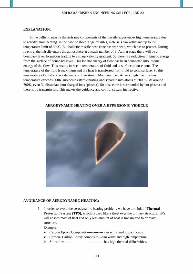
SRI RAMAKRISHNA ENGINEERING COLLEGE , CBE-22
111
EXPLANATION:
In the ballistic missile the airframe components of the missile experiences high temperature due
to aerodynamic heating. In the case of short range missiles, materials can withstand up to the
temperature limit of 300C. But ballistic missile nose cone has war head, which has to protect. During
re entry, the missile enters the atmosphere at a mach number of 8. At that stage there will be a
boundary layer formation leading to a sharp velocity gradient. So there is a reduction in kinetic energy
from the surface of boundary layer. This kinetic energy of flow has been connected into internal
energy of the flow. This results in rise in temperature of fluid and at surface of nose cone. The
temperature of the fluid is maximum and the heat is transferred from fluid to solid surface. So this
temperature of solid surface depends on free stream Mach number. At very high mach, when
temperature exceeds 800K, molecules start vibrating and separate into atoms at 2000K. At around
700K, even N2 dissociate into charged ions (plasma). So nose cone is surrounded by hot plasma and
there is no transmission. This makes the guidance and control system ineffective.
AERODYNAMIC HEATING OVER A HYPERSONIC VEHICLE
AVOIDANCE OF AERODYNAMIC HEATING:
1. In order to avoid the aerodynamic heating problem, we have to think of Thermal
Protection System (TPS), which is used like a sheet over the primary structure. TPS
will absorb most of heat and only less amount of heat is transmitted to primary
structure.
Example:
Carbon Epoxy Composite-------------- can withstand impact loads.
Carbon- Carbon Epoxy composite---can withstand high temperature.
Silica tiles -------------------------------- has high thermal diffusivities.
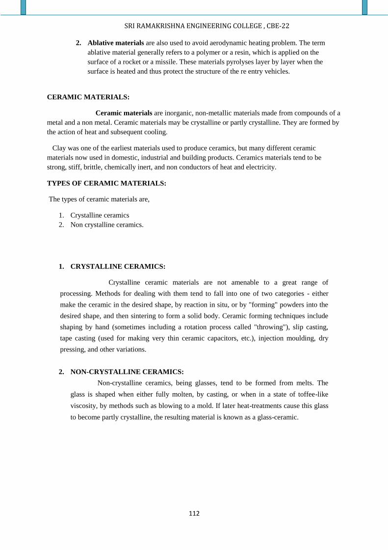
SRI RAMAKRISHNA ENGINEERING COLLEGE , CBE-22
112
2. Ablative materials are also used to avoid aerodynamic heating problem. The term
ablative material generally refers to a polymer or a resin, which is applied on the
surface of a rocket or a missile. These materials pyrolyses layer by layer when the
surface is heated and thus protect the structure of the re entry vehicles.
CERAMIC MATERIALS:
Ceramic materials are inorganic, non-metallic materials made from compounds of a
metal and a non metal. Ceramic materials may be crystalline or partly crystalline. They are formed by
the action of heat and subsequent cooling.
Clay was one of the earliest materials used to produce ceramics, but many different ceramic
materials now used in domestic, industrial and building products. Ceramics materials tend to be
strong, stiff, brittle, chemically inert, and non conductors of heat and electricity.
TYPES OF CERAMIC MATERIALS:
The types of ceramic materials are,
1. Crystalline ceramics
2. Non crystalline ceramics.
1. CRYSTALLINE CERAMICS:
Crystalline ceramic materials are not amenable to a great range of
processing. Methods for dealing with them tend to fall into one of two categories - either
make the ceramic in the desired shape, by reaction in situ, or by "forming" powders into the
desired shape, and then sintering to form a solid body. Ceramic forming techniques include
shaping by hand (sometimes including a rotation process called "throwing"), slip casting,
tape casting (used for making very thin ceramic capacitors, etc.), injection moulding, dry
pressing, and other variations.
2. NON-CRYSTALLINE CERAMICS:
Non-crystalline ceramics, being glasses, tend to be formed from melts. The
glass is shaped when either fully molten, by casting, or when in a state of toffee-like
viscosity, by methods such as blowing to a mold. If later heat-treatments cause this glass
to become partly crystalline, the resulting material is known as a glass-ceramic.
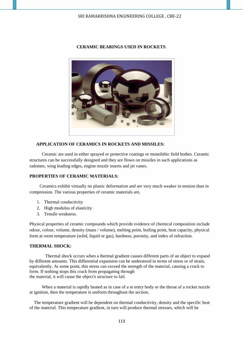
SRI RAMAKRISHNA ENGINEERING COLLEGE , CBE-22
113
CERAMIC BEARINGS USED IN ROCKETS.
APPLICATION OF CERAMICS IN ROCKETS AND MISSILES:
Ceramic are used in either sprayed or protective coatings or monolithic field bodies. Ceramic
structures can be successfully designed and they are flown on missiles in such applications as
radomes, wing leading edges, engine nozzle inserts and jet vanes.
PROPERTIES OF CERAMIC MATERIALS:
Ceramics exhibit virtually no plastic deformation and are very much weaker in tension than in
compression. The various properties of ceramic materials are,
1. Thermal conductivity
2. High modulus of elasticity
3. Tensile weakness.
Physical properties of ceramic compounds which provide evidence of chemical composition include
odour, colour, volume, density (mass / volume), melting point, boiling point, heat capacity, physical
form at room temperature (solid, liquid or gas), hardness, porosity, and index of refraction.
THERMAL SHOCK:
Thermal shock occurs when a thermal gradient causes different parts of an object to expand
by different amounts. This differential expansion can be understood in terms of stress or of strain,
equivalently. At some point, this stress can exceed the strength of the material, causing a crack to
form. If nothing stops this crack from propagating through
the material, it will cause the object's structure to fail.
When a material is rapidly heated as in case of a re entry body or the throat of a rocket nozzle
at ignition, then the temperature is uniform throughout the section.
The temperature gradient will be dependent on thermal conductivity, density and the specific heat
of the material. This temperature gradient, in turn will produce thermal stresses, which will be
SRI RAMAKRISHNA ENGINEERING COLLEGE , CBE-22
114
dependent on the coefficient of thermal expansion of the material.
Thermal shocks are not confined to ceramic materials alone, but these materials are more
susceptible to the thermal shock when compared to most other materials. Many metals are thermal
shock sensitive, particularly upon sudden chilling. At low temperature the cold side will be placed in
tension and in these metals which have high ductile brittle transition temperatures. Due to thermal
shock fracture can also occur.
MATRIAL SELECTION CONSIDERATION FOR ROCKETS:
The selection criteria for materials for rockets are,
1. High strength at elevated temperature
2. Ease of fabrication
3. High thermal conductivity
4. Resistance to chemical action to vapours
5. High specific heat
6. Resistance to corrosion
7. Resistance to mechanical and thermal shock
8. High melting point
9. Low thermal expansion
10. Good vibration resistance.
SELECTION CRITERIA FOR MATERIALS FOR SPACE CRAFT STRUCTURES:
Extreme working temperature
High value of strength to weight ratio
Strength should not deteriorate at extreme temperature to lower acceptable limit
The material can able to withstand,
1. Shock or pressure load
2. Thermal load
3. Impact loads
Material should not lose its properties when exposed to cyclic loads.
MATERIALS THAT CAN BE USED IN DIFFERENT PARTS OF ROCKETS AND
MISSILES
SHORT RANGE TACTICAL MISSILE:
NOSE:
Air –to-Air missiles:
For IR homing, quartz or arsenic trisulphide glass molded to shape or fabricated with stainless steel
heat sink at tip of the nose. For active homing, fiberglass reinforced resin impregnated RADOME
(clipped word: Radar + dome shape) molded.
Surface-to-Air missile:
For IR homing, quartz or arsenic trisulphide glass molded to shape or fabricated with stainless steel
heat sink at tip of the nose. For active homing, fiberglass reinforced resin impregnated RADOME
(clipped word: Radar + dome shape) molded.
SRI RAMAKRISHNA ENGINEERING COLLEGE , CBE-22
115
Air-to-surface missile:
For IR homing, quartz or Arsenic trisulphide glass molded to shape or fabricated with stainless steel
heat sink at the tip. For some active homing, fiberglass reinforced resin impregnated RADOME
molded and the warhead would be encased in steel or aluminum alloys.
Fore bodies:
In all cases the structure would be of aluminum alloys or steel.the most commonly used material is
the aluminum alloy.
Rear bodies:
Same as the fore body except that where the rear body consists of propulsion system or its
components like combustion chamber, steel and steel alloys are used. If weight reduction is required
in aft position, magnesium alloy may be used in boat tail section.
Wings and fins:
Normally aluminum alloy plates at required geometric shapes were used. Reinforced fiber glass resin
impregnated composite structures can also be used for this application. In this case metal inserts
would be need for leading edges if the missile speed were high.
Nozzles:
Mostly steel with graphite or molybdenum inserts with or without ceramic coatings were used.
MEDIUM RANGE TACTICAL MISSILE:
Same as for short range tactical missiles except that the greater portion of the structure will be made
of steel. Jettisioning devices, boosters are mainly made of fiberglass reinforced resin impregnated
structures.
Generally aluminum alloy, titanium alloy, stainless steel, inconel, hastalloys, ceramic coatings were
used in medium range tactical missiles.
LONG RANGE MISSILES:
NOSE SECTION:
Inter Continental Ballistic Missile warheads are encased in austenitic stainless steel types of AISI 321
type with ablative coatings. For drag type re entry bodies with payload at electronic equipment are
well insulated and encased in stainless steel or fiberglass reinforced impregnated composite structures
with ablative coatings. In the case of fiberglass reinforced structures, they must be stiffened by a skin
of stainless steel of austenitic type on the inside surface. For glide type re entry bodies like manned
capsules, the construction would be of space structures with materials either stainless steel or
composites with radiation or micro meteoroid shields.
MAIN BODIES:
Generally of austenitic stainless steel of type AISI 347 or AISI 327 with critical parts made of chrome
molybdenum vanadium ferritic steel are used. Sometimes titanium or boron fiber reinforced structures
SRI RAMAKRISHNA ENGINEERING COLLEGE , CBE-22
116
depending on the requirement are also used. If the liquid propellants are used the material should with
the fluids. The tank structure should be also stiffened with longerons and frames with baffles to
prevent propellant sloshing.
INTERSTAGE COUPLINGS:
Generally austenitic steel are used in inter stage couplings.
WINGS AND FINS:
Usually stainless steel materials are used. The geometry is fabricated with stringers for stiffening.
Leading edges can be inserted with titanium based metal inserts.
NOZZLES:
Usually composite structures with graphite inserts with ceramic coatings are used. Sometimes
molybdenum inserts are also used.
ANSWER IN SHORT:
1. What are the factors to be considered for the material selection in rockets?
2. What are the factors to be considered for the material selection in spacecraft?
3. What is meant by aerodynamic heating?
4. What is known as TPS? Give examples.
5. What is an ablative material and where it can be used in rockets and missiles?
6. What are the properties and applications of ceramic materials?
7. Define the term thermal shock.
8. What are the metallic materials that are used in rocket nozzles
9. What are the parts of a rocket which are exposed to high temperatures?
10. What is meant by ablation?
BRIEF ANSWERS:
1. What is aerodynamic heating? Clearly explain how to avoid aerodynamic heating
phenomena?
2. Explain the various metallic materials that can be used for different parts of rockets and
missiles
3. Explain briefly about ceramic materials and explain the applications of such materials in
rockets and missiles.
4. Elaborately explain the term thermal shock