rocketplane kistler, inc. · rocketplane kistler, inc. document no. k1m-002 rev. a 4300 amelia...
TRANSCRIPT

Rocketplane Kistler, Inc. Document No. K1M-002 Rev. A 4300 Amelia Earhart Ln March 2007 Oklahoma City, OK 73159 K-1 Vehicle User’s Guide Volume 2- Satellite Payload Modules and Active Dispenser
Rocketplane Kistler, Inc.
MODEL NO: K-1 REPORT NO: K1M-002 Rev. A DATE: March 30, 2007
K-1 Vehicle Users Guide Volume 2 Satellite Payload Modules and Active Dispenser

Rocketplane Kistler, Inc. Document No. K1M-002 Rev. A 4300 Amelia Earhart Ln March 2007 Oklahoma City, OK 73159 K-1 Vehicle User’s Guide Volume 2- Satellite Payload Modules and Active Dispenser
Page i
REVISION HISTORY REV DATE CHANGE CHANGE
AUTHORITY AFFECTED PAGE(S)
N/C 05-15-02 Initial Release P22-0003
A 03-30-07 Revised Into Volumes, Updated Content.
MD27-001 All
Rocketplane Kistler, Inc. Document No. K1M-002 Rev. A 4300 Amelia Earhart Ln March 2007 Oklahoma City, OK 73159 K-1 Vehicle User’s Guide Volume 2- Satellite Payload Modules and Active Dispenser
Page ii
FOREWORD Rocketplane Kistler is preparing to initiate commercial launch services using its fully reusable K-1 launch vehicle. Volume 2 of the K-1 Vehicle User’s Guide provides detail on the K-1 Payload Modules and Active Dispenser.
Volume 1 of the K-1 Vehicle User’s Guide provides information to potential customers regarding the K-1 vehicle, operations, mission planning and integration, and launch operations and facilities.
This volume will be periodically updated. All comments and suggestions for additional information are welcome.
For any clarifications or comments, please contact:
Tad Theno
Rocketplane Kistler
4300 Amelia Earhart Lane
Oklahoma City, OK 73159
1-877-238-0057 x105
Website: www.kistleraerospace.com
Electronic copies of the K-1 Vehicle User’s Guide may be obtained from Rocketplane Kistler website at www.kistleraerospace.com. Hardcopies are available upon request.
© Copyright 2007 Rocketplane Kistler, Inc. All rights reserved.

Rocketplane Kistler, Inc. Document No. K1M-002 Rev. A 4300 Amelia Earhart Ln March 2007 Oklahoma City, OK 73159 K-1 Vehicle User’s Guide Volume 2- Satellite Payload Modules and Active Dispenser
Page iii
TABLE OF CONTENTS REVISION HISTORY ............................................................................................................................... i
FOREWORD ........................................................................................................................................... ii
TABLE OF CONTENTS ........................................................................................................................ iii
LIST OF FIGURES AND TABLES ......................................................................................................... v
ABBREVIATIONS AND ACRONYMS ................................................................................................... vi
1. INTRODUCTION TO VOLUME 2 .................................................................................................... 7
2. K-1 SATELLITE PAYLOAD MODULES OVERVIEW ..................................................................... 8 2.1 Introduction .............................................................................................................................. 8 2.2 Satellite Payload Module Description ....................................................................................... 8
2.2.1 Satellite Envelope ....................................................................................................... 8 2.3 Satellite Launch Process Flow ................................................................................................. 8 2.4 Payload Interface ................................................................................................................... 11
2.4.1 Mechanical Interfaces ............................................................................................... 11 2.4.2 Electrical Interfaces ................................................................................................... 11
3. K-1 ACTIVE DISPENSER ............................................................................................................. 14 3.1 Introduction ............................................................................................................................ 14 3.2 Technical Description ............................................................................................................. 14 3.3 Propulsion System ................................................................................................................. 15 3.4 Structures and Thermal Protection......................................................................................... 15 3.5 Avionics .................................................................................................................................. 15 3.6 K-1 Payload Module for Active Dispenser Missions ............................................................... 15
3.6.1 General Description and Operation .......................................................................... 16 3.6.2 Satellite Envelope ..................................................................................................... 17
3.7 Active Dispenser and Payload Interfaces............................................................................... 17 3.7.1 Mechanical Interfaces ............................................................................................... 17 3.7.2 Electrical Interfaces ................................................................................................... 17
4. VEHICLE PERFORMANCE .......................................................................................................... 19 4.1 Introduction ............................................................................................................................ 19 4.2 Mission Profiles ...................................................................................................................... 19
4.2.1 Ascent Profile ............................................................................................................ 19 4.2.2 Satellite Deployment ................................................................................................. 19 4.2.3 Collision and Contamination Avoidance Maneuvers ................................................ 24
4.3 Performance Capability .......................................................................................................... 24 4.4 K-1 Orbit Insertion Accuracy .................................................................................................. 26 4.5 Active Dispenser Performance Capability .............................................................................. 26
4.5.1 Active Dispenser Orbit Insertion Accuracy ................................................................ 29 5. SATELLITE ENVIRONMENTS ..................................................................................................... 30
5.1 Introduction ............................................................................................................................ 30
Rocketplane Kistler, Inc. Document No. K1M-002 Rev. A 4300 Amelia Earhart Ln March 2007 Oklahoma City, OK 73159 K-1 Vehicle User’s Guide Volume 2- Satellite Payload Modules and Active Dispenser
Page iv
5.2 Pre-Launch Environments ...................................................................................................... 30 5.2.1 Satellite Air Conditioning ........................................................................................... 30 5.2.2 Acoustics, Vibration, and Shock ............................................................................... 30 5.2.3 Thermal & Humidity................................................................................................... 30 5.2.4 Electrostatic Potential ............................................................................................... 30 5.2.5 Cleanliness/Contamination ....................................................................................... 30 5.2.6 EMI and RF Environments ........................................................................................ 31
5.3 Flight Environments................................................................................................................ 31 5.3.1 Steady-State Acceleration ........................................................................................ 31 5.3.2 Combined Loads ....................................................................................................... 31 5.3.3 Acoustics ................................................................................................................... 32 5.3.4 Vibration .................................................................................................................... 33 5.3.5 Shock Loads ............................................................................................................. 33 5.3.6 Thermal ..................................................................................................................... 33 5.3.7 Ascent Venting .......................................................................................................... 33 5.3.8 Cleanliness/Contamination ....................................................................................... 34
5.4 Satellite Design and Verification Requirements ..................................................................... 34 5.4.1 Factors of Safety ....................................................................................................... 34 5.4.2 Structural Load Tests ................................................................................................ 34 5.4.3 Acoustic Testing ........................................................................................................ 34 5.4.4 Vibration Test ............................................................................................................ 34 5.4.5 Fit Check, Separation, and Shock Test ................................................................... 35

Rocketplane Kistler, Inc. Document No. K1M-002 Rev. A 4300 Amelia Earhart Ln March 2007 Oklahoma City, OK 73159 K-1 Vehicle User’s Guide Volume 2- Satellite Payload Modules and Active Dispenser
Page v
LIST OF FIGURES AND TABLES Figure 2-1 Standard Payload Module ................................................................................................... 9 Figure 2-2 Standard and Extended Payload Module Dynamic Envelopes ........................................... 9 Figure 2-3 Satellite Process Flow ....................................................................................................... 10 Figure 2-5 Satellite Integration Flow ................................................................................................... 11 Figure 2-6 Adapter Mechanical Interface ............................................................................................ 11 Figure 2-7 Customer and Launch Control Electrical Interfaces .......................................................... 12 Figure 2-8 OV and Satellite adapter Electrical Interface ..................................................................... 13 Figure 3-1 K-1 Active Dispenser and Satellite in ADPM ..................................................................... 14 Figure 3-4 Active Dispenser Payload Module Dynamic Envelope with Active Dispenser ................... 17 Figure 3-5 Baseline Active Dispenser Standard Mechanical Interface ............................................... 18 Figure 4-1 K-1 Vehicle Ascent Profile for 900 km Mission .................................................................. 20 Figure 4-2 Ascent Acceleration Profile ................................................................................................ 21 Figure 4-3 Ascent Altitude and Velocity Profile ................................................................................... 21 Figure 4-4 Satellite Deployment Sequence ........................................................................................ 23 Figure 4-5 Axial Satellite Deployment - Standard Payload Module .................................................... 23 Figure 4-6 Radial Satellite Deployment – Standard Payload Module ................................................. 23 Figure 4-8 Post Deployment Clearance .............................................................................................. 25 Figure 4-9 Circular Orbit Performance with SPM ................................................................................ 25 Figure 4-10 Circular Orbit Performance with EPM ................................................................................ 26 Figure 4-11 Active Dispenser Circular Orbit Performance to 45 degree and 90 degree Inclinations ... 27 Figure 4-12 Active Dispenser Equatorial Orbit Performance ................................................................ 27 Figure 4-13 Active Dispenser Elliptical Orbit Performance to 45 degree Inclination ............................. 28 Figure 4-14 Active Dispenser Performance to Escape Trajectories ..................................................... 28 Figure 5-1 Maximum Axial Acceleration ............................................................................................. 31 Figure 5-2 Acoustic Environment (1/3 Octave Band Level) ................................................................ 32 Figure 5-3 Random Vibration .............................................................................................................. 33 Figure 5-4 Shock Environment ........................................................................................................... 33 Figure 5-5 PM Inner Surface Temperature ......................................................................................... 33 Figure 5-6 Depressurization Rate During Ascent ............................................................................... 33 Table 4-1 Mission Event Sequence for 900 km Orbit Woomera Launch ............................................ 22 Table 4-2 K-1 Orbit Insertion Accuracy ............................................................................................... 26 Table 4-3 Active Dispenser Orbit Insertion Accuracy for a Nominal 35,000 km x 4200 km GTO ....... 29 Table 5-1 Design Limit Load Factors .................................................................................................. 32 Table 5-2 Satellite Design Factors of Safety ....................................................................................... 34 Table 5-3 Satellite Acoustic Test Margins and Durations ................................................................... 34 Table 5-4 Satellite Random Vibration Test Margins and Durations .................................................... 34

Rocketplane Kistler, Inc. Document No. K1M-002 Rev. A 4300 Amelia Earhart Ln March 2007 Oklahoma City, OK 73159 K-1 Vehicle User’s Guide Volume 2- Satellite Payload Modules and Active Dispenser
Page vi
ABBREVIATIONS AND ACRONYMS ACS Attitude Control System ADPM Active Dispenser Payload Module EGI Embedded Global Positioning System/Inertial Navigation System EPM Extended Payload Module GEO geosynchronous orbit GN&C Guidance, Navigation, and Control GTO geosynchronous transfer orbit hr hour kg kilogram km kilometer LAP Launch Assist Platform lbf pounds force lbm pounds mass LEO low earth orbit MECO main-engine cutoff MEO medium-earth orbit min minute mm millimeters MMH monomethyl hydrazine N newtons N2O4 nitrogen tetroxide OMS Orbital Maneuvering System OV Orbital Vehicle RAAN right ascension of ascending node RF radio frequency Sec second TDRSS Tracking Data Relay Satellite System TVC thrust vector control V volts

Rocketplane Kistler, Inc. Document No. K1M-002 Rev. A 4300 Amelia Earhart Ln March 2007 Oklahoma City, OK 73159 K-1 Vehicle User’s Guide Volume 2- Satellite Payload Modules and Active Dispenser
Page 7
1. INTRODUCTION TO VOLUME 2 Rocketplane Kistler uses the satellite payload module integrated with the K-1 OV/LAP to provide low-cost, reliable satellite launch services to Low Earth Orbit (LEO). The K-1's reusability and modular design will enable quick turnaround times for launch campaigns, ensuring rapid and reliable access to space.
The K-1 will be capable of servicing high-energy orbit missions with the addition of an Active Dispenser. This is an ideal solution for the small medium-earth orbit (MEO) and geosynchronous (GEO) satellites and interplanetary science missions that seek inexpensive, reliable space access.
Volume 1 of the User’s Guide describes the K-1 vehicle and RpK’s approach to mission planning and integration, ground and launch operations, and services. Volume 2 is a companion document and describes the payload modules and the Active Dispenser. The available envelope, performance, interfaces, environment and operations are provided for each module/dispenser.

Rocketplane Kistler, Inc. Document No. K1M-002 Rev. A 4300 Amelia Earhart Ln March 2007 Oklahoma City, OK 73159 K-1 Vehicle User’s Guide Volume 2- Satellite Payload Modules and Active Dispenser
Page 8
2. K-1 SATELLITE PAYLOAD MODULES OVERVIEW 2.1 Introduction Satellites are carried by the K-1 vehicle inside the reusable satellite payload module mounted on top of the OV. This section describes the satellite payload modules and their operation.
The K-1 satellite payload modules perform the same function for the satellite as does the fairing of an expendable vehicle. In contrast to a typical fairing, however, the K-1 satellite payload modules are fully reusable and provide the forward reentry heat shield for the OV. Satellite payload modules are interchangeable to provide maximum flight schedule flexibility.
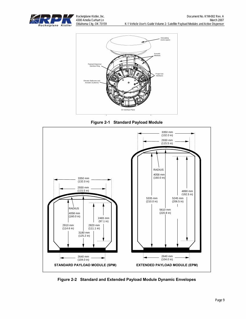
2.2 Satellite Payload Module Description The K-1 vehicle offers the satellite launch customer two satellite payload module configurations: the Standard Payload Module (SPM) and the Extended Payload Module (EPM). The EPM has about twice the usable height of the SPM.
The satellite payload modules are fabricated from composite materials and use redundant, high-reliability mechanisms. The satellite payload module configurations incorporate interior acoustic absorption blankets and have integral pre-launch environmental control systems.
Figure 2-1 shows the Standard Payload Module. The structure consists of a composite cylindrical section sealed at the top with a dome. The satellite dispenser is mounted to the bottom deck of the satellite payload module. Satellite conditioned air and electrical interfaces are provided at the base. The
inside surface is covered in acoustic blankets. The outer surface is covered with thermally-protective materials to withstand reentry heating.
2.2.1 Satellite Envelope The allowable dynamic envelope within the satellite payload modules for the SPM and EPM are shown in Figure 2-2.
2.3 Satellite Launch Process Flow The satellite is received at the Payload Processing Facility (PPF) and undergoes preparation and checkout. In parallel to the satellite processing, the satellite payload module enters the Payload Processing Facility for maintenance, preparation and check out prior to satellite integration. Figure 2-3 shows the process flow for the satellite. Figure 2-4 shows a typical schedule for processing an all new satellite for launch on the K-1.
Once the satellite functional tests are performed and fueling is complete, a combined RpK/customer team performs a vertical integration of the satellite with the satellite payload module. These steps are graphically shown in Figure 2-5. A conditioned air flow is maintained for satellite temperature control from final encapsulation until launch. The satellite payload module is then transported to the VPF for final integration with the OV.
The integrated K-1 vehicle is transported to the launch site, erected, fueled, and launched, as discussed in volume 1.
Rocketplane Kistler, Inc. Document No. K1M-002 Rev. A 4300 Amelia Earhart Ln March 2007 Oklahoma City, OK 73159 K-1 Vehicle User’s Guide Volume 2- Satellite Payload Modules and Active Dispenser
Page 9
AcousticBlankets
Purge GasInterfaces
Payload DispenserInterface Ring
OV Interface Plane
ArticulatingDome (open)
Elevator Ballscrew andActuator (3 places)
Figure 2-1 Standard Payload Module
STANDARD PAYLOAD MODULE (SPM) EXTENDED PAYLOAD MODULE (EPM)
2640 mm(104.0 in)
2930 mm(115.5 in)
2930 mm(115.5 in)
3350 mm(132.0 in)
3350 mm(132.0 in)
2640 mm(104.0 in)
2820 mm(111.1 in)
2910 mm(114.6 in)
4890 mm(192.5 in)
5245 mm(206.5 in)
5335 mm(210.0 in)
RADIUS
4058 mm(160.0 in)
2465 mm(97.1 in)
RADIUS
4058 mm(160.0 in)
3180 mm(125.2 in)
5610 mm(220.8 in)
Figure 2-2 Standard and Extended Payload Module Dynamic Envelopes

Rocketplane Kistler, Inc. Document No. K1M-002 Rev. A 4300 Amelia Earhart Ln March 2007 Oklahoma City, OK 73159 K-1 Vehicle User’s Guide Volume 2- Satellite Payload Modules and Active Dispenser
Page 10
Recover OV Remove PM from OV
Prep and c/oPM
Integrate PM and Satellite
Receive Satellite
Prepare Satellite
Mate PM and OV / LAP
Transfer K-1 to Launch Stand
Launch K-1 Vehicle
OV / LAP Processing
Recover OV Remove PM from OV
Prep and c/oPM
Integrate PM and Satellite
Receive Satellite
Prepare Satellite
Mate PM and OV / LAP
Transfer K-1 to Launch Stand
Launch K-1 Vehicle
OV / LAP Processing
Figure 2-3 Satellite Process Flow
Figure 2-4 Typical Satellite Mission Schedule

Rocketplane Kistler, Inc. Document No. K1M-002 Rev. A 4300 Amelia Earhart Ln March 2007 Oklahoma City, OK 73159 K-1 Vehicle User’s Guide Volume 2- Satellite Payload Modules and Active Dispenser
Page 11
Overhead Crane(Max Load = 10,000 kg)PPF Airlock
PPF PayloadIntegration Class
100,000
Clean Room
1. Receive Payload Module
2. Payload Module Clean ing & Checkout
PPF Airlock
5. Payload Module Test & Checkout
3. Payload In t egrat ion
4. Payload Module Closeout
Figure 2-5 Satellite Integration Flow
2.4 Payload Interface This section describes the mechanical and electrical interfaces between the K-1 satellite payload module and the satellite/dispenser. The reusable K-1 vehicle allows for refurbishment and reuse of the satellite adapter. The adapter can either be supplied by the customer or developed by RpK to customer requirements.
2.4.1 Mechanical Interfaces The satellite adapter provides the interface between the satellite and the satellite payload module. Reusable satellite adapters can be provided to meet the interface requirements of the customer, including standard V-band clamp systems or custom bolted interfaces. The specific
design and development approach is arranged with each customer. The adapter mounts to the adapter attach ring using thirty evenly spaced bolts. Figure 2-6 shows this interface.
2300.00[90.55]
20 x 5.055[.199]
20 x 5.055 mm[0.199 in]
0 x 6.528 mm[0.257 in]
2300 mm[90.55 in]
Figure 2-6 Adapter Mechanical Interface
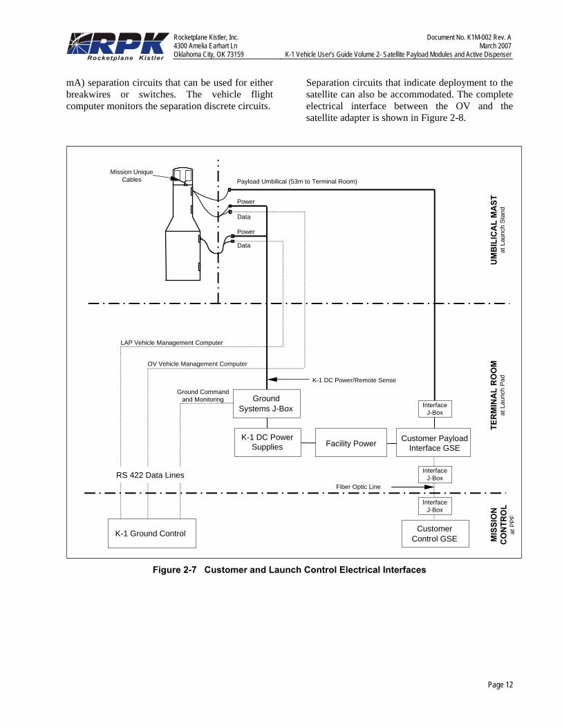
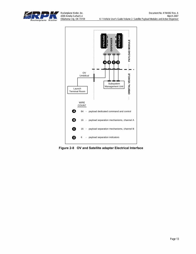
2.4.2 Electrical Interfaces The electrical interface with the satellite is made through a dedicated umbilical following final integration of the satellite adapter with the satellite payload module. This umbilical provides ground power, battery charging, and hardwired command and telemetry links between the satellite and the customer-supplied ground support equipment (GSE). The customer GSE is located in the Terminal Room under the launch pad. Fiber optic control lines are provided for remote operation of the GSE from the PPF. Figure 2-7 shows an overview of customer electrical interfaces at the launch site. A total of eighty-four 16-gauge wires are available for customer use in the satellite umbilical. The flyaway satellite umbilical is available for use until liftoff.
In addition to the satellite umbilical, two vehicle harnesses are dedicated to the satellite separation system and one to separation indication. The vehicle avionics are capable of simultaneously issuing six 6-amp pyro commands through redundant channels. The vehicle avionics also provide three payload-to-dispenser low level (5
Rocketplane Kistler, Inc. Document No. K1M-002 Rev. A 4300 Amelia Earhart Ln March 2007 Oklahoma City, OK 73159 K-1 Vehicle User’s Guide Volume 2- Satellite Payload Modules and Active Dispenser
Page 12
mA) separation circuits that can be used for either breakwires or switches. The vehicle flight computer monitors the separation discrete circuits.
Separation circuits that indicate deployment to the satellite can also be accommodated. The complete electrical interface between the OV and the satellite adapter is shown in Figure 2-8.
Payload Umbilical (53m to Terminal Room)
Power
Data
Power
MIS
SIO
NC
ON
TRO
Lat
PPF
K-1 Ground Control CustomerControl GSE
Facility Power
GroundSystems J-Box
K-1 DC PowerSupplies
Customer PayloadInterface GSE
Data
LAP Vehicle Management Computer
Ground Commandand Monitoring
InterfaceJ-Box
InterfaceJ-Box
InterfaceJ-Box
Fiber Optic Line
K-1 DC Power/Remote Sense
OV Vehicle Management Computer
TER
MIN
AL
RO
OM
at L
aunc
h Pa
dU
MB
ILIC
AL
MA
STat
Lau
nch
Stan
d
Mission UniqueCables
RS 422 Data Lines
Figure 2-7 Customer and Launch Control Electrical Interfaces
Rocketplane Kistler, Inc. Document No. K1M-002 Rev. A 4300 Amelia Earhart Ln March 2007 Oklahoma City, OK 73159 K-1 Vehicle User’s Guide Volume 2- Satellite Payload Modules and Active Dispenser
Page 13
PAYL
OA
D M
OD
ULE
SubsystemManagement Unit
LaunchTerminal Room
DIS
PEN
SER
C DA B
PAYL
OA
D
PAYL
OA
D
OVUmbilical
OR
BIT
AL
VEH
ICLE
84 - payload dedicated command and control
16 - payload separation mechanisms, channel A
16 - payload separation mechanisms, channel B
6 - payload separation indicators
C
D
A
B
WIRECOUNT
Figure 2-8 OV and Satellite adapter Electrical Interface
Rocketplane Kistler, Inc. Document No. K1M-002 Rev. A 4300 Amelia Earhart Ln March 2007 Oklahoma City, OK 73159 K-1 Vehicle User’s Guide Volume 2- Satellite Payload Modules and Active Dispenser
Page 14
3. K-1 ACTIVE DISPENSER 3.1 Introduction For K-1 customers requiring delivery of satellites to high-energy orbits, RpK offers the option of a K-1 Active Dispenser. This section provides an overall technical description of the K-1 Active Dispenser system.
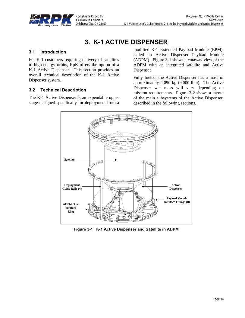
3.2 Technical Description The K-1 Active Dispenser is an expendable upper stage designed specifically for deployment from a
modified K-1 Extended Payload Module (EPM), called an Active Dispenser Payload Module (ADPM). Figure 3-1 shows a cutaway view of the ADPM with an integrated satellite and Active Dispenser.
Fully fueled, the Active Dispenser has a mass of approximately 4,090 kg (9,000 lbm). The Active Dispenser wet mass will vary depending on mission requirements. Figure 3-2 shows a layout of the main subsystems of the Active Dispenser, described in the following sections.
DeploymentGuide Rails (4)
ADPM / OVInterface
Ring
Satellite
ActiveDispenser
Payload ModuleInterface Fittings (8)
DeploymentGuide Rails (4)
ADPM / OVInterface
Ring
Satellite
ActiveDispenser
Payload ModuleInterface Fittings (8)
Figure 3-1 K-1 Active Dispenser and Satellite in ADPM

Rocketplane Kistler, Inc. Document No. K1M-002 Rev. A 4300 Amelia Earhart Ln March 2007 Oklahoma City, OK 73159 K-1 Vehicle User’s Guide Volume 2- Satellite Payload Modules and Active Dispenser
Page 15
Stabilization Struts (8)
Main Tanks (4)Main Engine
SC Adapter Interface
He Bottle
Separation BoltRetainers (8)
Thrust Cone
Controllers (3)
S-Band Antennasand Transmitters (2)
Stabilization Struts (8)
Main Tanks (4)Main Engine
SC Adapter Interface
He Bottle
Separation BoltRetainers (8)
Thrust Cone
Controllers (3)
S-Band Antennasand Transmitters (2)
Figure 3-2 Major Components of the K-1 Active Dispenser
3.3 Propulsion System The Active Dispenser uses a single restartable engine for main propulsion, providing 8,960 N (2,000 lbf) of thrust in vacuum conditions. The engine Thrust Vector Control (TVC) system is the same system used on the K-1 Orbital Maneuvering System (OMS), capable of hydraulically gimbaling the nozzle +/- 6 degrees in pitch and yaw. The Active Dispenser uses storable, high-performance nitrogen tetroxide (N2O4) and monomethyl hydrazine (MMH) for main propulsion, with a nozzle expansion ratio of 200:1. Propellant tanks are pressurized by helium. Monopropellant hot-gas thrusters are used for attitude control, utilizing the hydrazine from the main propulsion tanks in conjunction with a catalyst bed.
3.4 Structures and Thermal Protection The Active Dispenser’s four propellant tanks provide the primary load-bearing structure of the Active Dispenser. Composite stabilization struts provide additional support. The Active Dispenser is attached to the base of ADPM with eight pneumatic separation bolts (two at each corner). A multiple layer aluminized mylar thermal shield protects the Active
Dispenser’s avionics and the payload from the engine plume. Main engine components and the spacecraft interface are mounted to a composite thrust cone.
3.5 Avionics The Active Dispenser’s avionics architecture is modeled after the system used on the K-1, utilizing the same Honeywell Embedded Global Positioning System/ Inertial Navigation System (EGI) for control. An additional card is added to each EGI to perform Guidance, Navigation, and Control (GN&C) tasks. The system uses a triplex computing architecture with three cross-strapped controllers and a hardware voter. Dual S-band transmitters provide communication for separation indication.
3.6 K-1 Payload Module for Active Dispenser Missions
For Active Dispenser missions, satellites are carried by the K-1 vehicle inside an ADPM, a modified EPM mounted on top of the OV. This section describes the ADPM and its operation.
Rocketplane Kistler, Inc. Document No. K1M-002 Rev. A 4300 Amelia Earhart Ln March 2007 Oklahoma City, OK 73159 K-1 Vehicle User’s Guide Volume 2- Satellite Payload Modules and Active Dispenser
Page 16
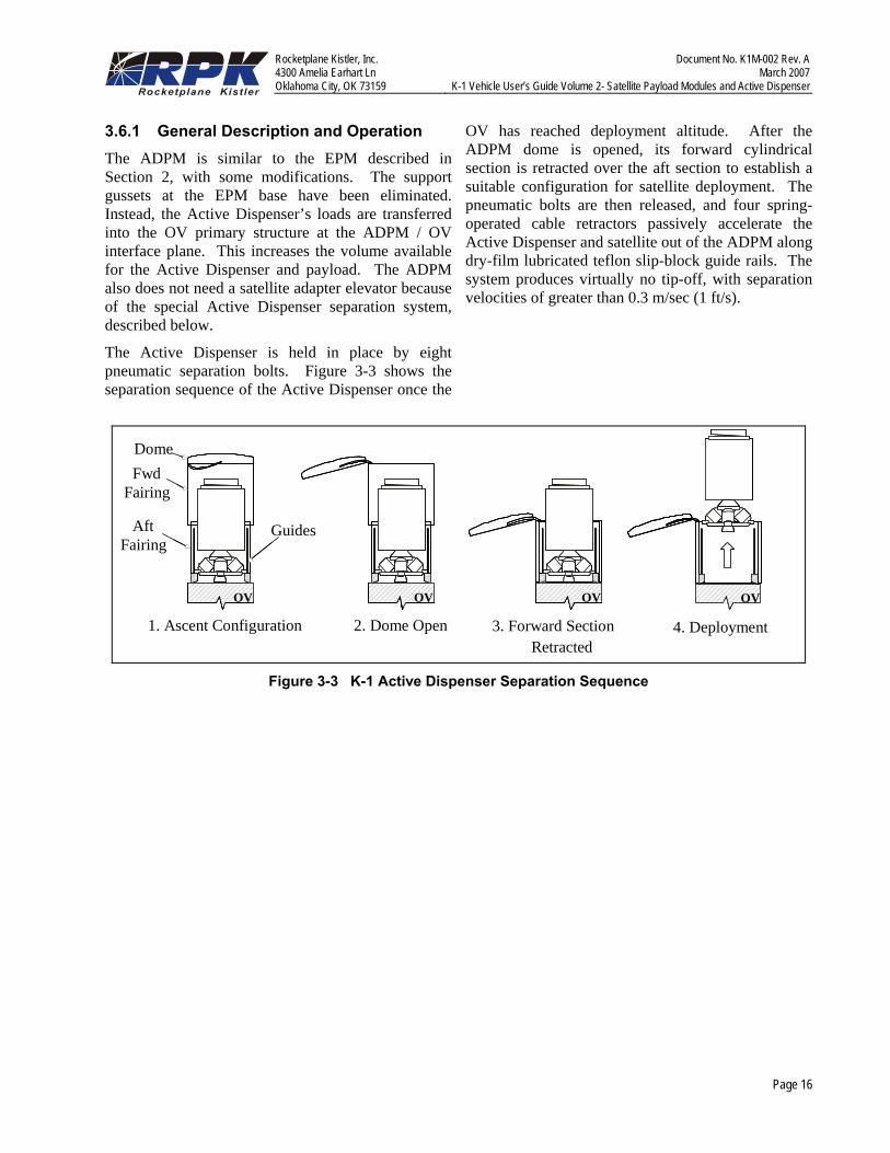
3.6.1 General Description and Operation The ADPM is similar to the EPM described in Section 2, with some modifications. The support gussets at the EPM base have been eliminated. Instead, the Active Dispenser’s loads are transferred into the OV primary structure at the ADPM / OV interface plane. This increases the volume available for the Active Dispenser and payload. The ADPM also does not need a satellite adapter elevator because of the special Active Dispenser separation system, described below.
The Active Dispenser is held in place by eight pneumatic separation bolts. Figure 3-3 shows the separation sequence of the Active Dispenser once the
OV has reached deployment altitude. After the ADPM dome is opened, its forward cylindrical section is retracted over the aft section to establish a suitable configuration for satellite deployment. The pneumatic bolts are then released, and four spring-operated cable retractors passively accelerate the Active Dispenser and satellite out of the ADPM along dry-film lubricated teflon slip-block guide rails. The system produces virtually no tip-off, with separation velocities of greater than 0.3 m/sec (1 ft/s).
OV
1. Ascent Configuration
OV
2. Dome Open
OV
3. Forward Section Retracted
4. Deployment
OV
Dome Fwd
Fairing
Aft Fairing
Guides
OV OV OV OVOVOVOV OVOVOVOV OVOVOV
Dome Fwd
Fairing
Aft Fairing
Guides
Figure 3-3 K-1 Active Dispenser Separation Sequence
Rocketplane Kistler, Inc. Document No. K1M-002 Rev. A 4300 Amelia Earhart Ln March 2007 Oklahoma City, OK 73159 K-1 Vehicle User’s Guide Volume 2- Satellite Payload Modules and Active Dispenser
Page 17
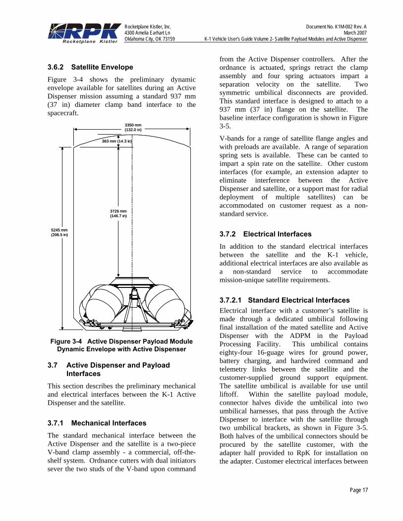
3.6.2 Satellite Envelope Figure 3-4 shows the preliminary dynamic envelope available for satellites during an Active Dispenser mission assuming a standard 937 mm (37 in) diameter clamp band interface to the spacecraft.
5245 mm(206.5 in)
3350 mm(132.0 in)
3726 mm(146.7 in)
363 mm (14.3 in)
5245 mm(206.5 in)
3350 mm(132.0 in)
3726 mm(146.7 in)
363 mm (14.3 in)
Figure 3-4 Active Dispenser Payload Module
Dynamic Envelope with Active Dispenser
3.7 Active Dispenser and Payload Interfaces
This section describes the preliminary mechanical and electrical interfaces between the K-1 Active Dispenser and the satellite.
3.7.1 Mechanical Interfaces The standard mechanical interface between the Active Dispenser and the satellite is a two-piece V-band clamp assembly - a commercial, off-the-shelf system. Ordnance cutters with dual initiators sever the two studs of the V-band upon command
from the Active Dispenser controllers. After the ordnance is actuated, springs retract the clamp assembly and four spring actuators impart a separation velocity on the satellite. Two symmetric umbilical disconnects are provided. This standard interface is designed to attach to a 937 mm (37 in) flange on the satellite. The baseline interface configuration is shown in Figure 3-5.
V-bands for a range of satellite flange angles and with preloads are available. A range of separation spring sets is available. These can be canted to impart a spin rate on the satellite. Other custom interfaces (for example, an extension adapter to eliminate interference between the Active Dispenser and satellite, or a support mast for radial deployment of multiple satellites) can be accommodated on customer request as a non-standard service.
3.7.2 Electrical Interfaces In addition to the standard electrical interfaces between the satellite and the K-1 vehicle, additional electrical interfaces are also available as a non-standard service to accommodate mission-unique satellite requirements.
3.7.2.1 Standard Electrical Interfaces Electrical interface with a customer’s satellite is made through a dedicated umbilical following final installation of the mated satellite and Active Dispenser with the ADPM in the Payload Processing Facility. This umbilical contains eighty-four 16-guage wires for ground power, battery charging, and hardwired command and telemetry links between the satellite and the customer-supplied ground support equipment. The satellite umbilical is available for use until liftoff. Within the satellite payload module, connector halves divide the umbilical into two umbilical harnesses, that pass through the Active Dispenser to interface with the satellite through two umbilical brackets, as shown in Figure 3-5. Both halves of the umbilical connectors should be procured by the satellite customer, with the adapter half provided to RpK for installation on the adapter. Customer electrical interfaces between

Rocketplane Kistler, Inc. Document No. K1M-002 Rev. A 4300 Amelia Earhart Ln March 2007 Oklahoma City, OK 73159 K-1 Vehicle User’s Guide Volume 2- Satellite Payload Modules and Active Dispenser
Page 18
the satellite and their GSE remain as shown in Figure 2-7.
The three vehicle harnesses dedicated to satellite separation and separation indication in the SPM and EPM are used on K-1 Active Dispenser missions to separate the Active Dispenser from the modified EPM. The Active Dispenser contains its own redundant circuits for satellite separation actuation and for satellite separation indication. Following separation, the Active Dispenser transmits a state vector from its triplex EGIs through its dual S-band transceivers for relay to the spacecraft mission control center.
3.7.2.2 Non-Standard Electrical Interfaces As a non-standard service, up to eight discrete in flight commands in the form of relay closures are
available to the satellite during the launch phase and prior to separation from the Active Dispenser.
As a non-standard service, RpK can provide launch phase telemetry to the satellite. For launch phase telemetry, up to three channels of data are available at data rates up to approximately 4 kbps. During the K-1’s ascent phase and before separation of the Active Dispenser, telemetry is routed through the Active Dispenser S-band communication system. A RF horn internal to the satellite payload module feeds an external antenna mounted on the satellite payload module exterior. This system can also be used on the ground for RF link tests. Telemetry after separation of the Active Dispenser is provided directly through the S-band system. The downlink is to a customer ground station, commercial ground station, or through TDRSS.
Bolt Cutter(2 places)
UmbilicalBracket(2 places)
SeparationSpring(4 places)
Clamp Extractor(16 places)
ClampAssembly
Bolt Cutter(2 places)
UmbilicalBracket(2 places)
SeparationSpring(4 places)
Clamp Extractor(16 places)
ClampAssembly
Bolt Cutter(2 places)
UmbilicalBracket(2 places)
SeparationSpring(4 places)
Clamp Extractor(16 places)
ClampAssembly
1219 mm(48 in)
826 mm(32.5 in)
945 mm(37.2 in)
Figure 3-5 Baseline Active Dispenser Standard Mechanical Interface
Rocketplane Kistler, Inc. Document No. K1M-002 Rev. A 4300 Amelia Earhart Ln March 2007 Oklahoma City, OK 73159 K-1 Vehicle User’s Guide Volume 2- Satellite Payload Modules and Active Dispenser
Page 19
4. VEHICLE PERFORMANCE4.1 Introduction This section defines the performance capability of the K-1 vehicle to low earth orbit.
4.2 Mission Profiles The K-1 vehicle ascent, satellite deployment, and post-deployment maneuvers are described in this section.
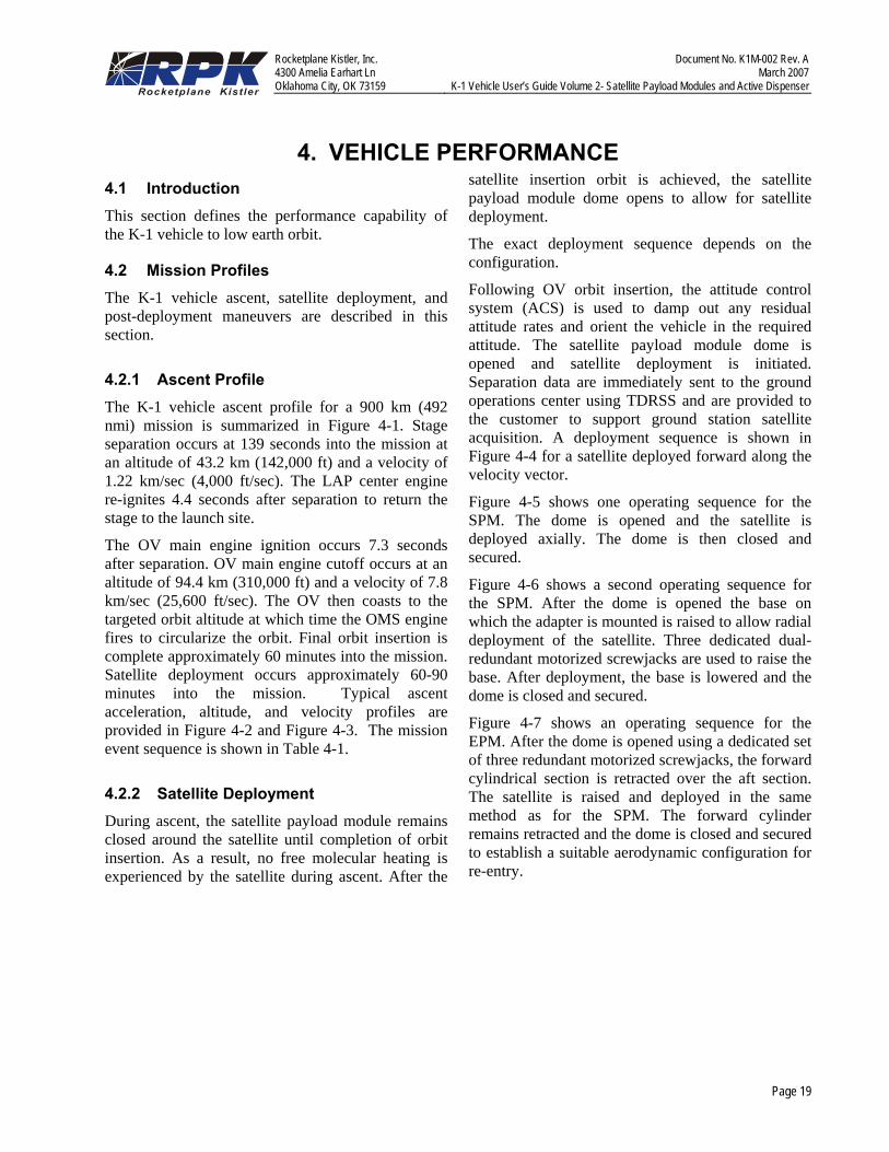
4.2.1 Ascent Profile The K-1 vehicle ascent profile for a 900 km (492 nmi) mission is summarized in Figure 4-1. Stage separation occurs at 139 seconds into the mission at an altitude of 43.2 km (142,000 ft) and a velocity of 1.22 km/sec (4,000 ft/sec). The LAP center engine re-ignites 4.4 seconds after separation to return the stage to the launch site.
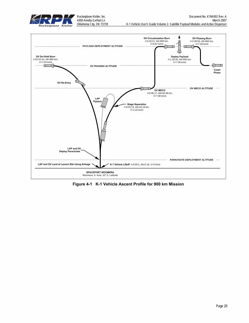
The OV main engine ignition occurs 7.3 seconds after separation. OV main engine cutoff occurs at an altitude of 94.4 km (310,000 ft) and a velocity of 7.8 km/sec (25,600 ft/sec). The OV then coasts to the targeted orbit altitude at which time the OMS engine fires to circularize the orbit. Final orbit insertion is complete approximately 60 minutes into the mission. Satellite deployment occurs approximately 60-90 minutes into the mission. Typical ascent acceleration, altitude, and velocity profiles are provided in Figure 4-2 and Figure 4-3. The mission event sequence is shown in Table 4-1.
4.2.2 Satellite Deployment During ascent, the satellite payload module remains closed around the satellite until completion of orbit insertion. As a result, no free molecular heating is experienced by the satellite during ascent. After the
satellite insertion orbit is achieved, the satellite payload module dome opens to allow for satellite deployment.
The exact deployment sequence depends on the configuration.
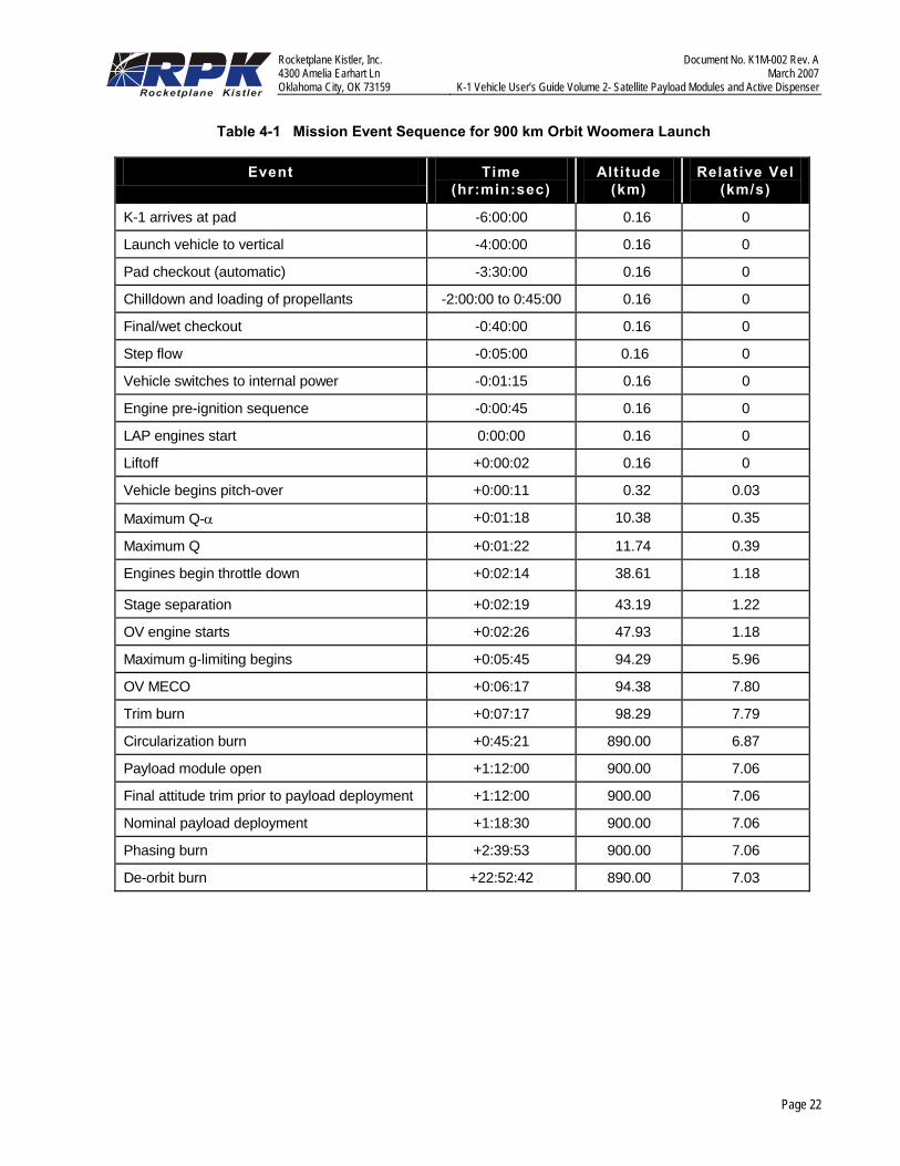
Following OV orbit insertion, the attitude control system (ACS) is used to damp out any residual attitude rates and orient the vehicle in the required attitude. The satellite payload module dome is opened and satellite deployment is initiated. Separation data are immediately sent to the ground operations center using TDRSS and are provided to the customer to support ground station satellite acquisition. A deployment sequence is shown in Figure 4-4 for a satellite deployed forward along the velocity vector.
Figure 4-5 shows one operating sequence for the SPM. The dome is opened and the satellite is deployed axially. The dome is then closed and secured.
Figure 4-6 shows a second operating sequence for the SPM. After the dome is opened the base on which the adapter is mounted is raised to allow radial deployment of the satellite. Three dedicated dual-redundant motorized screwjacks are used to raise the base. After deployment, the base is lowered and the dome is closed and secured.
Figure 4-7 shows an operating sequence for the EPM. After the dome is opened using a dedicated set of three redundant motorized screwjacks, the forward cylindrical section is retracted over the aft section. The satellite is raised and deployed in the same method as for the SPM. The forward cylinder remains retracted and the dome is closed and secured to establish a suitable aerodynamic configuration for re-entry.
Rocketplane Kistler, Inc. Document No. K1M-002 Rev. A 4300 Amelia Earhart Ln March 2007 Oklahoma City, OK 73159 K-1 Vehicle User’s Guide Volume 2- Satellite Payload Modules and Active Dispenser
Page 20
PAYLOAD DEPLOYMENT ALTITUDE
OV PHASING ALTITUDE
OV MECO ALTITUDE
PARACHUTE DEPLOYMENT ALTITUDE
OV Phasing Burnt=2:39:53, Alt=900 km,
V=7.06 km/s
OV De-Orbit Burnt=22:52:42, Alt=890 km,
V=7.03 km/s
OV Re-Entry
LAPFlyback
SPACEPORT WOOMERAWoomera, S. Aust. 31º S. Latitude
Stage Separationt=0:02:19, Alt=43.19 km,
V=1.22 km/s
CoastPhase
Deploy Payloadt=1:18:30, Alt=900 km,
V=7.06 km/s
OV Circularization Burnt=0:45:21, Alt=890 km,
V=6.87 km/s
LAP and OVDeploy Parachutes
LAP and OV Land at Launch Site Using Airbags K-1 Vehicle Liftoff t=0:00:2, Alt=0.16, V=0 km/s
OV MECOt=0:06:17, Alt=94.38 km,
V=7.80 km/s
Figure 4-1 K-1 Vehicle Ascent Profile for 900 km Mission

Rocketplane Kistler, Inc. Document No. K1M-002 Rev. A 4300 Amelia Earhart Ln March 2007 Oklahoma City, OK 73159 K-1 Vehicle User’s Guide Volume 2- Satellite Payload Modules and Active Dispenser
Page 21
0
1
2
3
4
5
6
7
00:00 00:43 01:26 02:10 02:53 03:36 04:19 05:02 05:46 06:29
Time From Liftoff (min:sec)
OV Ignition
Start Throttling of OV
OV EngineCutoff
Lap Stage Engine Cutoff
Phased EngineShutdown Sequence
Stage Separation
OV at 100%Tthrust
Axi
al A
ccel
erat
ion
(g)
Figure 4-2 Ascent Acceleration Profile
0
100
200
300
400
500
600
700
800
900
1,000
0:00 0:16 0:32 0:48 1:04 1:21
Time From Liftoff (hr:min)
Alti
tude
(km
)
0
1
2
3
4
5
6
7
8
9
Rel
ativ
e Ve
loci
ty (k
m/s
ec)
StageSeparation
OV MECO
Trim Burn
Circularization BurnOrbit Insertion
Complete
Altitude
Velocity
Figure 4-3 Ascent Altitude and Velocity Profile
Rocketplane Kistler, Inc. Document No. K1M-002 Rev. A 4300 Amelia Earhart Ln March 2007 Oklahoma City, OK 73159 K-1 Vehicle User’s Guide Volume 2- Satellite Payload Modules and Active Dispenser
Page 22
Table 4-1 Mission Event Sequence for 900 km Orbit Woomera Launch
Event Time (hr:min:sec)
Alt itude (km)
Relative Vel (km/s)
K-1 arrives at pad -6:00:00 0.16 0
Launch vehicle to vertical -4:00:00 0.16 0
Pad checkout (automatic) -3:30:00 0.16 0
Chilldown and loading of propellants -2:00:00 to 0:45:00 0.16 0
Final/wet checkout -0:40:00 0.16 0
Step flow -0:05:00 0.16 0
Vehicle switches to internal power -0:01:15 0.16 0
Engine pre-ignition sequence -0:00:45 0.16 0
LAP engines start 0:00:00 0.16 0
Liftoff +0:00:02 0.16 0
Vehicle begins pitch-over +0:00:11 0.32 0.03
Maximum Q-α +0:01:18 10.38 0.35
Maximum Q +0:01:22 11.74 0.39
Engines begin throttle down +0:02:14 38.61 1.18
Stage separation +0:02:19 43.19 1.22
OV engine starts +0:02:26 47.93 1.18
Maximum g-limiting begins +0:05:45 94.29 5.96
OV MECO +0:06:17 94.38 7.80
Trim burn +0:07:17 98.29 7.79
Circularization burn +0:45:21 890.00 6.87
Payload module open +1:12:00 900.00 7.06
Final attitude trim prior to payload deployment +1:12:00 900.00 7.06
Nominal payload deployment +1:18:30 900.00 7.06
Phasing burn +2:39:53 900.00 7.06
De-orbit burn +22:52:42 890.00 7.03
Rocketplane Kistler, Inc. Document No. K1M-002 Rev. A 4300 Amelia Earhart Ln March 2007 Oklahoma City, OK 73159 K-1 Vehicle User’s Guide Volume 2- Satellite Payload Modules and Active Dispenser
Page 23
Dome Open Orient OV for Deployment
Deploy Payload
Dome Closed
Orient for Phasing Burn
Orbit Insertion
Figure 4-4 Satellite Deployment Sequence
Unlock and Open Dome
Close and Lock Dome
DeployPayload
Figure 4-5 Axial Satellite Deployment - Standard Payload Module
Unlock and Open Dome, Unlock Elevator
Lower and Lock Elevator Close and Lock Dome
Radial Deploymentof Payloads
Raise Elevator
Figure 4-6 Radial Satellite Deployment – Standard Payload Module

Rocketplane Kistler, Inc. Document No. K1M-002 Rev. A 4300 Amelia Earhart Ln March 2007 Oklahoma City, OK 73159 K-1 Vehicle User’s Guide Volume 2- Satellite Payload Modules and Active Dispenser
Page 24
Unlock and Open Dome
Close and Lock Dome
DeployPayload
Retract ForwardFairing
Figure 4-7 Axial Satellite Deployment – Extended Payload Module
4.2.3 Collision and Contamination Avoidance Maneuvers
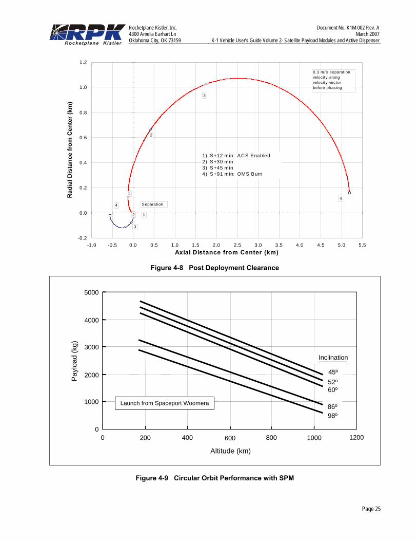
The OV post-deployment maneuvers are designed to eliminate the possibility of re-contact with or contamination of the customer’s satellite. A representative post-deployment clearance profile is shown in Figure 4-8. Following deployment, the adapter and satellite payload module are prepared for re-entry. These operations take approximately 12 minutes, during which time the hot gas ACS system is disabled. When the ACS system is enabled for rate-damping operations, the OV is greater than 200 m (660 ft) from the customer’s satellite assuming a minimum separation velocity of 0.3 m/sec (1 ft/sec). The OV then coasts until the proper time to orient for the OMS phasing burn.
Sufficient clearance after deployment is provided to eliminate any collision or contamination concerns. The phasing burn is required to establish the proper orbit period to allow the OV to return to the launch site. Depending on the deployment altitude, the phasing burn can either raise apogee or lower perigee. In either case, the typical phasing orbit is elliptical with a different orbit period than that of the deployed satellite.
The phasing burn occurs approximately 90 minutes after satellite separation. At this time, the OV and the satellite are greater than 5 km (16,400 ft) apart. At
this distance, OMS plume contamination and environmental issues are eliminated.
The distance between the OV and the satellite is greater than 1000 km (540 nmi) 5 hours after the phasing burn, and continues to increase because of the difference in orbit periods.
4.3 Performance Capability This section presents the K-1 satellite capability. Data are provided for both Standard and Extended Payload Module configurations. The performance estimates are based on propellant budgets that include 3-sigma flight performance reserves (FPR).
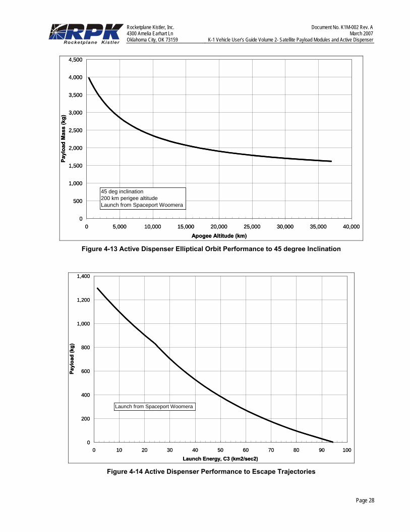
The K-1 vehicle is designed primarily to deliver satellites to circular low earth orbits. The K-1 vehicle LEO performance for the Standard Payload Module (SPM) is provided in Figure 4-9 and for the Extended Payload Module (EPM) in Figure 4-10, for several specific orbit inclinations. Satellite capability for other orbits can be obtained by interpolation. Performance to elliptical or higher energy orbits can be addressed on a case-by-case basis.
Customers are welcome to contact RpK to discuss specific mission requirements and associated satellite performance.
Rocketplane Kistler, Inc. Document No. K1M-002 Rev. A 4300 Amelia Earhart Ln March 2007 Oklahoma City, OK 73159 K-1 Vehicle User’s Guide Volume 2- Satellite Payload Modules and Active Dispenser
Page 25
-0.2
0.0
0.2
0.4
0.6
0.8
1.0
1.2
-1.0 -0.5 0.0 0.5 1.0 1.5 2.0 2.5 3.0 3.5 4.0 4.5 5.0 5.5Axial Distance from Center (km)
Rad
ial D
ista
nce
from
Cen
ter (
km)
1) S+12 min: ACS Enabled2) S+30 min3) S+45 min4) S+91 min: OMS Burn
2
3
14
Separation
12
3
4
0.3 m/s separation veloc ity along veloc ity vector before phasing
Figure 4-8 Post Deployment Clearance
0
1000
2000
3000
4000
5000
0 200 400 600 800 1000 1200
Altitude (km)
Pay
load
(kg)
Inclination
45º52º60º
86º98º
Launch from Spaceport Woomera
Figure 4-9 Circular Orbit Performance with SPM

Rocketplane Kistler, Inc. Document No. K1M-002 Rev. A 4300 Amelia Earhart Ln March 2007 Oklahoma City, OK 73159 K-1 Vehicle User’s Guide Volume 2- Satellite Payload Modules and Active Dispenser
Page 26
0
1000
2000
3000
4000
5000
0 200 400 600 800 1000 1200
Altitude (km)
Pay
load
(kg)
Inclination
45º52º60º
86º98º
Launch from Spaceport Woomera
Figure 4-10 Circular Orbit Performance with EPM
4.4 K-1 Orbit Insertion Accuracy The K-1 vehicle orbit insertion accuracy is summarized in Table 4-2. Highly accurate orbit insertion is ensured through the use of the OV OMS to correct post-MECO velocity errors and to provide final orbit insertion. These accuracies are valid for all orbits < 1000 km.
Table 4-2 K-1 Orbit Insertion Accuracy
Parameter K-1 Accuracy (3σ )
Orbit altitude ±10 km
Eccentricity ±0.01
Inclination ±0.05 degrees
Right Ascension of Ascending Node (RAAN)
±0.04 degrees
4.5 Active Dispenser Performance Capability
Using its restartable main propulsion system, the Active Dispenser is adaptable to a range of missions, including LEO orbit raising, LEO plane-changes, MEO, GTO, GEO, or interplanetary missions.
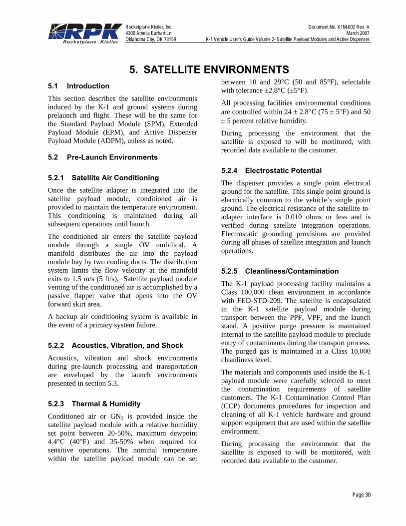
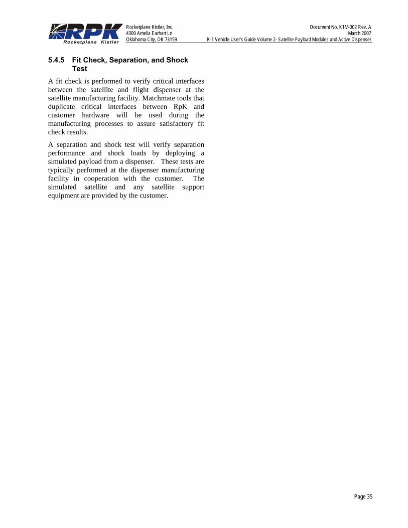
Figure 4-11 through Figure 4-14 show the Active Dispenser’s design performance to various orbits. Figure 4-11 shows the Active Dispenser’s design performance to circular orbits inclined 45° and 90°. Figure 4-12 shows design performance to circular equatorial orbits. Figure 4-13 shows design performance to elliptical orbits inclined 45°. Figure 4-14 shows design performance for escape trajectories. The performance curves are based on propellant budgets that include 3-sigma flight performance reserves.
Performance presented does not assume de-orbit of the Active Dispenser. Performance to other drop-off orbits, or performance incorporating Active Dispenser de-orbit, is available upon request.

Rocketplane Kistler, Inc. Document No. K1M-002 Rev. A 4300 Amelia Earhart Ln March 2007 Oklahoma City, OK 73159 K-1 Vehicle User’s Guide Volume 2- Satellite Payload Modules and Active Dispenser
Page 27
0
500
1,000
1,500
2,000
2,500
3,000
3,500
4,000
4,500
0 5,000 10,000 15,000 20,000 25,000 30,000 35,000 40,000Circular Altitude (km)
Payl
oad
Mas
s (k
g)
Launch from Spaceport Woomera
45 degrees
90 degrees
0
500
1,000
1,500
2,000
2,500
3,000
3,500
4,000
4,500
0 5,000 10,000 15,000 20,000 25,000 30,000 35,000 40,000Circular Altitude (km)
Payl
oad
Mas
s (k
g)
0
500
1,000
1,500
2,000
2,500
3,000
3,500
4,000
4,500
0 5,000 10,000 15,000 20,000 25,000 30,000 35,000 40,000Circular Altitude (km)
Payl
oad
Mas
s (k
g)
Launch from Spaceport Woomera
45 degrees
90 degrees
Figure 4-11 Active Dispenser Circular Orbit Performance to 45 degree and 90 degree Inclinations
0
100
200
300
400
500
600
700
800
900
1,000
0 5,000 10,000 15,000 20,000 25,000 30,000 35,000 40,000
Circular Altitude (km)
Payl
oad
Mas
s (k
g)
0 deg inclinationLaunch from Spaceport Woomera
0
100
200
300
400
500
600
700
800
900
1,000
0 5,000 10,000 15,000 20,000 25,000 30,000 35,000 40,000
Circular Altitude (km)
Payl
oad
Mas
s (k
g)
0 deg inclinationLaunch from Spaceport Woomera
Figure 4-12 Active Dispenser Equatorial Orbit Performance
Rocketplane Kistler, Inc. Document No. K1M-002 Rev. A 4300 Amelia Earhart Ln March 2007 Oklahoma City, OK 73159 K-1 Vehicle User’s Guide Volume 2- Satellite Payload Modules and Active Dispenser
Page 28
0
500
1,000
1,500
2,000
2,500
3,000
3,500
4,000
4,500
0 5,000 10,000 15,000 20,000 25,000 30,000 35,000 40,000
Apogee Altitude (km)
Payl
oad
Mas
s (k
g)
45 deg inclination200 km perigee altitudeLaunch from Spaceport Woomera
0
500
1,000
1,500
2,000
2,500
3,000
3,500
4,000
4,500
0 5,000 10,000 15,000 20,000 25,000 30,000 35,000 40,000
Apogee Altitude (km)
Payl
oad
Mas
s (k
g)
45 deg inclination200 km perigee altitudeLaunch from Spaceport Woomera
Figure 4-13 Active Dispenser Elliptical Orbit Performance to 45 degree Inclination
0
200
400
600
800
1,000
1,200
1,400
0 10 20 30 40 50 60 70 80 90 100
Launch Energy, C3 (km2/sec2)
Payl
oad
(kg)
Launch from Spaceport Woomera
0
200
400
600
800
1,000
1,200
1,400
0 10 20 30 40 50 60 70 80 90 100
Launch Energy, C3 (km2/sec2)
Payl
oad
(kg)
Launch from Spaceport Woomera
Figure 4-14 Active Dispenser Performance to Escape Trajectories

Rocketplane Kistler, Inc. Document No. K1M-002 Rev. A 4300 Amelia Earhart Ln March 2007 Oklahoma City, OK 73159 K-1 Vehicle User’s Guide Volume 2- Satellite Payload Modules and Active Dispenser
Page 29
4.5.1 Active Dispenser Orbit Insertion Accuracy
The Active Dispenser’s design orbit insertion accuracy is summarized in Table 4-3.
Table 4-3 Active Dispenser Orbit Insertion Accuracy for a Nominal 35,000 km x 4200 km
GTO
Parameter Accuracy (3σ ) Semi-major axis ± 70 km
Altitude of apogee ± 120 km
Altitude of perigee ± 20 km
Inclination ± 5 degrees
Period ± 170 seconds
Argument of Perigee ± 11 degrees
RAAN (Right Ascension of Ascending Node)
± 15 degrees
Rocketplane Kistler, Inc. Document No. K1M-002 Rev. A 4300 Amelia Earhart Ln March 2007 Oklahoma City, OK 73159 K-1 Vehicle User’s Guide Volume 2- Satellite Payload Modules and Active Dispenser
Page 30
5. SATELLITE ENVIRONMENTS5.1 Introduction This section describes the satellite environments induced by the K-1 and ground systems during prelaunch and flight. These will be the same for the Standard Payload Module (SPM), Extended Payload Module (EPM), and Active Dispenser Payload Module (ADPM), unless as noted.
5.2 Pre-Launch Environments
5.2.1 Satellite Air Conditioning Once the satellite adapter is integrated into the satellite payload module, conditioned air is provided to maintain the temperature environment. This conditioning is maintained during all subsequent operations until launch.
The conditioned air enters the satellite payload module through a single OV umbilical. A manifold distributes the air into the payload module bay by two cooling ducts. The distribution system limits the flow velocity at the manifold exits to 1.5 m/s (5 ft/s). Satellite payload module venting of the conditioned air is accomplished by a passive flapper valve that opens into the OV forward skirt area.
A backup air conditioning system is available in the event of a primary system failure.
5.2.2 Acoustics, Vibration, and Shock Acoustics, vibration and shock environments during pre-launch processing and transportation are enveloped by the launch environments presented in section 5.3.
5.2.3 Thermal & Humidity Conditioned air or GN2 is provided inside the satellite payload module with a relative humidity set point between 20-50%, maximum dewpoint 4.4°C (40°F) and 35-50% when required for sensitive operations. The nominal temperature within the satellite payload module can be set
between 10 and 29°C (50 and 85°F), selectable with tolerance ±2.8°C (±5°F).
All processing facilities environmental conditions are controlled within 24 ± 2.8°C (75 ± 5°F) and 50 ± 5 percent relative humidity.
During processing the environment that the satellite is exposed to will be monitored, with recorded data available to the customer.
5.2.4 Electrostatic Potential The dispenser provides a single point electrical ground for the satellite. This single point ground is electrically common to the vehicle’s single point ground. The electrical resistance of the satellite-to-adapter interface is 0.010 ohms or less and is verified during satellite integration operations. Electrostatic grounding provisions are provided during all phases of satellite integration and launch operations.
5.2.5 Cleanliness/Contamination The K-1 payload processing facility maintains a Class 100,000 clean environment in accordance with FED-STD-209. The satellite is encapsulated in the K-1 satellite payload module during transport between the PPF, VPF, and the launch stand. A positive purge pressure is maintained internal to the satellite payload module to preclude entry of contaminants during the transport process. The purged gas is maintained at a Class 10,000 cleanliness level.
The materials and components used inside the K-1 payload module were carefully selected to meet the contamination requirements of satellite customers. The K-1 Contamination Control Plan (CCP) documents procedures for inspection and cleaning of all K-1 vehicle hardware and ground support equipment that are used within the satellite environment.
During processing the environment that the satellite is exposed to will be monitored, with recorded data available to the customer.

Rocketplane Kistler, Inc. Document No. K1M-002 Rev. A 4300 Amelia Earhart Ln March 2007 Oklahoma City, OK 73159 K-1 Vehicle User’s Guide Volume 2- Satellite Payload Modules and Active Dispenser
Page 31
5.2.6 EMI and RF Environments At the launch site, the electromagnetic environment (EMI) to which the satellite is exposed is generated primarily from the vehicle itself. The K-1 vehicle’s TDRSS system is used for data uplink and downlink in the S-band at a total radiated power of approximately 5 watts. The electric field generated by the TDRSS system at the satellite is estimated to be less than 3.4 V/m.
There are no other sources of significant radio frequency (RF) environments. An RF hazard analysis is performed for each mission to verify that the customer’s satellite transmitters are compatible with vehicle avionics systems.
5.3 Flight Environments This section contains predicted K-1 flight environments. These levels will be verified during the flight test program. During operations, satellite payload module acceleration, vibration, acoustic, temperature, and pressure data are recorded and provided to the customer.
5.3.1 Steady-State Acceleration The maximum steady state axial K-1 acceleration occurs at the end of the OV main engine burn. Figure 5-1 shows a plot of maximum steady state axial acceleration as a function of satellite weight. The OV main engine is throttled during the last part of the burn to limit the acceleration.
4.0
4.2
4.4
4.6
4.8
5.0
5.2
5.4
5.6
5.8
6.0
0 1,000 2,000 3,000 4,000 5,000
Payload Weight (kg)
Ste
ady-
Sta
te A
ccel
erat
ion
(g's
)
Figure 5-1 Maximum Axial Acceleration
5.3.2 Combined Loads Dynamic loading inputs during liftoff, transonic, maximum dynamic pressure, separation, and main engine cutoff flight regimes are combined with the steady state accelerations to produce the combined loading environments experienced by the satellite. The final accelerations experienced by the satellite are a function of the satellite and dispenser stiffness characteristics.
Recommended satellite stiffness levels are 25 Hz axial and 10 Hz lateral. Secondary structure mode frequencies above 35 Hz are recommended to prevent coupling with K-1 modes. For satellite meeting these criteria, the design limit load factors of Table 5-1 apply. For satellite outside these levels, the results of the dynamic coupled loads analyses are used to provide a better definition of the loading environment.

Rocketplane Kistler, Inc. Document No. K1M-002 Rev. A 4300 Amelia Earhart Ln March 2007 Oklahoma City, OK 73159 K-1 Vehicle User’s Guide Volume 2- Satellite Payload Modules and Active Dispenser
Page 32
Table 5-1 Design Limit Load Factors
L imit Load Factors (g)
Load Case Axial ( 1 ) Lateral Ground transportation on K-1 ±1.0 0/-2.0
Liftoff +1.8 ±0.5
Maximum axial dynamic load @ OV MECO
+6.6/-2.2(2) ±1.0
Maximum transverse load during flight
+2.0 ±2.0
Stage separation +1.5 ±0.2
(1) Compression, - Tension
(2) The OV MECO dynamic axial load factor is 1.0g higher than the maximum static acceleration of Figure 8-1. The 6.6g value is based on a satellite mass of
1,500 kg (3307 lbm).
5.3.3 Acoustics The maximum satellite acoustic environment for the K-1 occurs during liftoff. The duration of exposure is less than 10 seconds. Typical levels for the K-1 Extended Payload Module are shown in Figure 5-2 for an equivalent cross-sectional fill area of 50%, corresponding to an equivalent satellite diameter of 2371 mm (93 in). Mission-specific acoustic analyses are performed to predict the environment given the size, shape, and overall dimensions of the customer’s satellite.
100
105
110
115
120
125
130
135
10 100 1000 10000
Frequency (Hz)
Soun
d Pr
essu
re L
evel
(dB
)
Overall SPL = 138 dB
1/3 Octave BandCenter Frequency (Hz)
Sound PressureLevel (dB)
20 12425 125
31.5 126.540 12850 128
62.5 12780 128.5
100 128.5125 128160 127.5200 125.7250 124.9315 124400 122500 120630 118.5800 118
1000 1171250 1161600 115.52000 1152500 1143200 1134000 112.55000 1116400 109.58000 108
Figure 5-2 Acoustic Environment (1/3 Octave Band Level)

Rocketplane Kistler, Inc. Document No. K1M-002 Rev. A 4300 Amelia Earhart Ln March 2007 Oklahoma City, OK 73159 K-1 Vehicle User’s Guide Volume 2- Satellite Payload Modules and Active Dispenser
Page 33
5.3.4 Vibration Random vibration levels for the satellite adapter attachment interface are shown in Figure 5-3. The random vibration levels bound expected sinusoidal vibration levels induced during ascent.
+8 dB/octave
6.06 GRMS
-3 dB/octave
Payload Dispenser Interface
Frequency (Hz)101 102 103 104
10-1
10-2
10-3
Pow
er S
pect
ral D
ens i
ty (g
2 /Hz)
Figure 5-3 Random Vibration
5.3.5 Shock Loads The maximum shock environment occurs at the satellite adapter interface during satellite separation from the K-1 vehicle. This environment is a function of the separation system configuration. The induced shock environment for a typical clampband satellite separation system at the satellite adapter interface is shown in Figure 5-4. A mission-specific shock analysis will be performed for each satellite adapter configuration prior to the satellite's first flight on the K-1 vehicle. The results of this analysis will be verified by a satellite separation test, as described in Section 5.4.
Acce
lera
tion
(g’s
)
Frequency (Hz)104103102101
104
103
102
101
100
Q = 10
Figure 5-4 Shock Environment
5.3.6 Thermal Figure 5-5 shows the inner fairing surface temperature profile for a typical mission during ascent. Since the K-1 satellite payload module remains closed until satellite deployment there is no free molecular heating on the satellite.
Inne
r Fai
ring
Tem
pera
ture
(deg
C)
Time After Liftoff (min)
10
0
50
40
30
20
10 20 30 40 50 60 70 800
Figure 5-5 PM Inner Surface Temperature
5.3.7 Ascent Venting During ascent, the satellite payload module compartment vents into the forward region of the OV. Valves in the base of the satellite payload module provide the vent path. The maximum pressure decay rate profile is shown in Figure 5-6. The peak decay rate of –3.7 kPa/sec (0.54 psi/sec) occurs for approximately 5 seconds.
Pea
k D
epre
ssur
izat
ion
Rat
e (-k
Pa/
sec)
0
1
2
3
4
5
0 25 50 75 100 125 150
Time After Liftoff (sec)
Figure 5-6 Depressurization Rate During Ascent

Rocketplane Kistler, Inc. Document No. K1M-002 Rev. A 4300 Amelia Earhart Ln March 2007 Oklahoma City, OK 73159 K-1 Vehicle User’s Guide Volume 2- Satellite Payload Modules and Active Dispenser
Page 34
5.3.8 Cleanliness/Contamination The design of the K-1 satellite payload module, satellite separation system, and cold gas attitude control system contributes to a contamination-free flight environment for the satellite. The satellite payload module is designed to limit the maximum level of satellite contaminants to 20 mg/m2
molecular and Level 750 particulate, in accordance with MIL-STD-1246.
5.4 Satellite Design and Verification Requirements
This section provides requirements guidelines for design and environmental testing of satellites intended for flight on the K-1 vehicle. Specific requirements will be mutually developed by the customer and the K-1 Program Office.
5.4.1 Factors of Safety The limit load factors for flight are given in Table 5-1. Ultimate load factors are obtained by multiplication of the limit load factors by the factors of safety listed in Table 5-2. The satellite must be capable of sustaining the loading cases derived from the ultimate load factors. The “test” factors apply to a satellite that will be verified by a static load test. If the satellite primary structure is to be demonstrated by analysis, the “no test” factors of safety shall be applied for design.
Table 5-2 Satellite Design Factors of Safety
Descript ion Test No Test Yield 1.05 1.60
Ultimate 1.33 2.00
5.4.2 Structural Load Tests Static load testing is performed by the customer to demonstrate the design integrity of the satellite primary structural elements. For satellite structures designed to the lower factor of safety levels of Table 5-2, the maximum limit load factors given in Table 5-1 are to be multiplied by 1.25 and 1.10 to determine the qualification and acceptance static test loads, respectively.
5.4.3 Acoustic Testing Satellite acoustic testing is required to assess both the workmanship of the satellite structure and the adequacy of component random vibration design and test levels. The spectrum of sound pressure levels to be used as a test specification is provided in Figure 5-2.
The acoustic margins and duration for qualification, proto-flight, and acceptance testing are defined Table 5-3.
Table 5-3 Satellite Acoustic Test Margins and Durations
Test Margin Durat ion Qualification + 3dB over
acceptance 120 sec, each axis
Proto-flight + 3dB over acceptance
60 sec, each axis
Acceptance Max. expected acoustic levels per para. 6.2.4
60 sec, each axis
5.4.4 Vibration Test The acceleration power spectral density to be used as a test specification is provided in Figure 5-3. This spectrum should be applied in all three axes. The random vibration margins and duration for qualification, proto-flight, and acceptance testing are defined in Table 5-4.
The random vibration test specification is expected to be the best simulation of the flight environments. For certain satellites or unique circumstances, a sinusoidal vibration test may be the best approach for qualification and acceptance testing. In this case, the K-1 Program Office will provide a sinusoidal vibration test specification.
Table 5-4 Satellite Random Vibration Test Margins and Durations
Test Margin Durat ion Qualification + 3dB over acceptance 60 sec
Proto-flight + 3dB over acceptance 20 sec
Acceptance Flight levels per para. 6.3.4
20 sec
Rocketplane Kistler, Inc. Document No. K1M-002 Rev. A 4300 Amelia Earhart Ln March 2007 Oklahoma City, OK 73159 K-1 Vehicle User’s Guide Volume 2- Satellite Payload Modules and Active Dispenser
Page 35
5.4.5 Fit Check, Separation, and Shock Test
A fit check is performed to verify critical interfaces between the satellite and flight dispenser at the satellite manufacturing facility. Matchmate tools that duplicate critical interfaces between RpK and customer hardware will be used during the manufacturing processes to assure satisfactory fit check results.
A separation and shock test will verify separation performance and shock loads by deploying a simulated payload from a dispenser. These tests are typically performed at the dispenser manufacturing facility in cooperation with the customer. The simulated satellite and any satellite support equipment are provided by the customer.